Embed Size (px)
Citation preview
* IN OT
CO •a •> <; ~:&'A
HYDROMECHANICS
O
AERODYNAMICS
STRUCTURAL MECHANICS
v.V •.v.*
M 0:
& Xvi -y
VV;
APPLIED MATHEMATICS
V.V
ACOUSTICS AND VIBRATION
M O D E L INVESTIGATION O F STABILITY AND CONTROL CHARACTERISTICS O F A P R E L I M I N A R Y DESIGN
FOR THE D E E P S U B M E R G E N C E RF.SCUE VESSEL (DSRV S C H E M E A)
by
J e r o m e P . F e l d m a n
Q
*8 U l w r* C/> , fe < P s L— ° S « 'S : EC c !o '-2
=33 5 --88
Vi
1 u 5
1 o O
{ek»
P-M
The d i s t r i b u t i o n of t h i s r e p o r t i s u n l i m i t e d
HYDROMECHANICS LABORATORY RESEARCH AND DEVELOPMENT REPORT
June 1966 R e p o r t 2249
PRNC-TMB-648 (R«v 1-64)
^teäÜ
.?
MODEL INVESTIGATION OF STABILITY AND CONTROL CHARACTERISTICS OF A PRELIMINAJIY DESIGN
FOR THE DEEP SUBMERGENCE RESCUE VESSEL (DSRV SCHEME A)
by
Jerome P. Feldman
The distribution of this report is unlimited
June 1966 Report 2249
I W ' ■■rfUtfiV-
TABLE OF CONTENTS
Page
ABSTRACT 1
INTRODUCTION 1
DESCRIPTION OF PROTOTYPE AND MODEL 2
TEST APPARATUS AND PROCEDURE 2
REDUCTION AND PRESENTATION OF DATA 6
DISCUSSION OF RESULTS 7
DYNAMIC STABILITY 7
SHROUD CONTROL EFFECTIVENESS 13
THRUSTER EFFECTIVENESS 14
Standstill Mode 15
Forward Speed Mode 14
Broadside Mode 34
CRITICAL SPEED AND EQUILIBRIUM CONDITIONS FOR LEVEL FLIGHT 34
CONCLUSIONS 40
ACKNOWLEDGMENTS 42
APPENDIX A - LONGITUDINAL STABILITY AND CONTROL COEFFICIENTS 43
APPENDIX B - LATERAL STABILITY COEFFICIENTS. 51
REFERENCES 57
ii
T"' - -31« —
ptf «Shr,
LIST OF FIGURES
Page
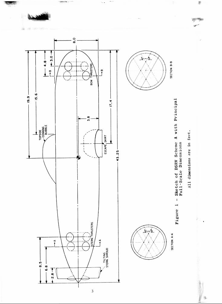
Figure 1 - Sketch of DSRV Scheme A with Principal Full-Scale Dimensions 3
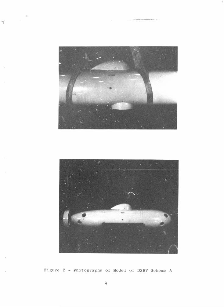
Figure 2 - Photographs of Model of DSRV Scheme A 4
Figure 3 - Variation of Vertical Plane Stability Roots with Speed. . 11
Figure 4 - Oscillatory Characteristics with Speed 12
Figure 5 - Effect of Velocity Coefficient on Normal Force Coefficient for Forward Thruster Pair 16
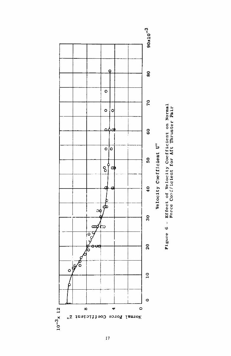
Figure 6 - Effect of Velocity Coefficient on Normal Force Coefficient for Aft Thruster Pair 17
Figure 7 - Effect of Velocity Coefficient on Torque Coefficient for Both Thruster Pairs 19
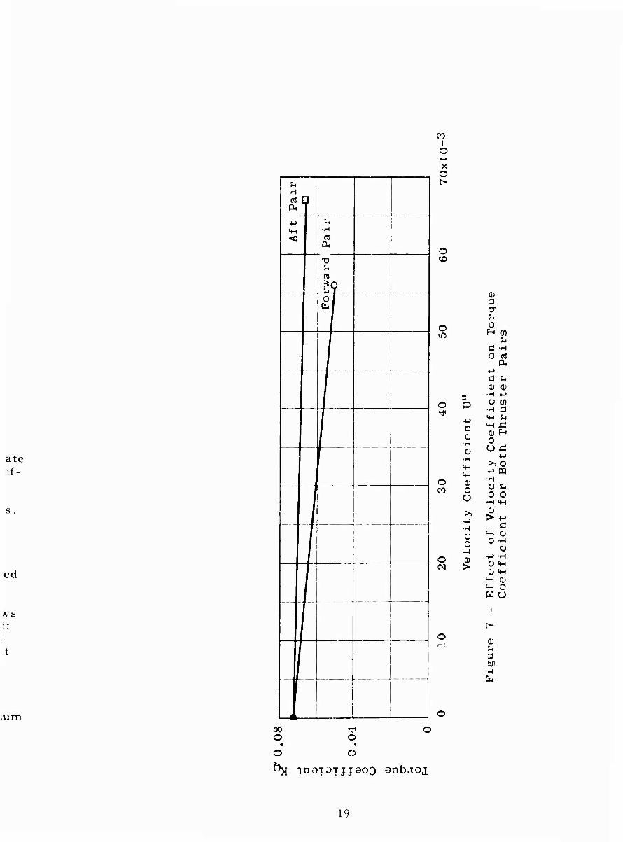
Figure 8 - Effect of Forward Speed on Normal Force for 10 Shaft Horsepower on Each Thruster Pair 20
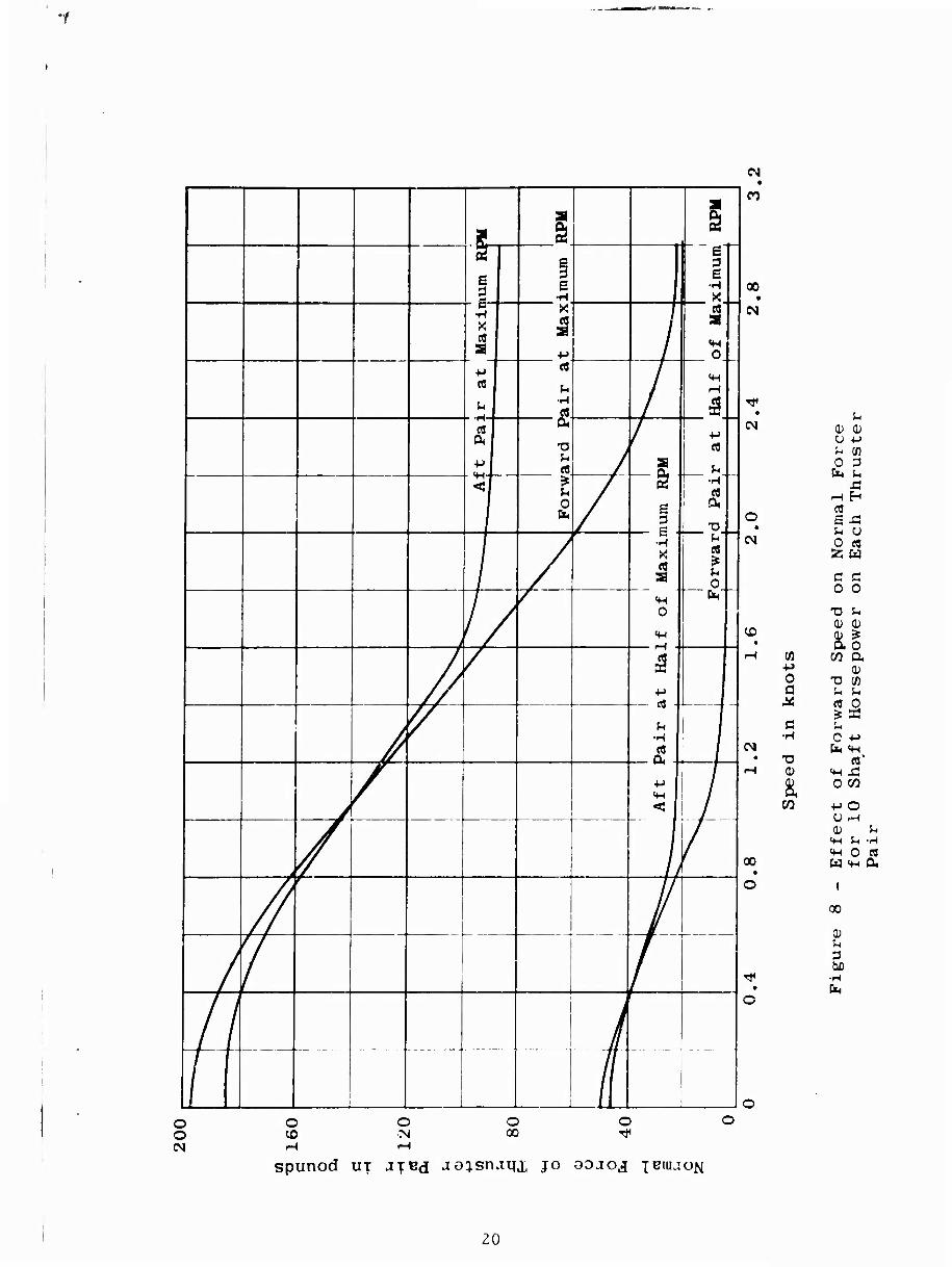
Figure 9 - Effect of RPM on Normal Force for Various Forward Spoeds and Shaft Horsepowers for Forward Thruster Fair 21
Figure 10 - Effect of RPM on Normal Force for Various Forward Speeds and Shaft Horsepowers for Aft Thruster Pair. . 22
Figure 11 - Effect of Velocity Coefficient on Normal Force Coefficient for the Forward and Aft Thruster Pairs Operating Together 24
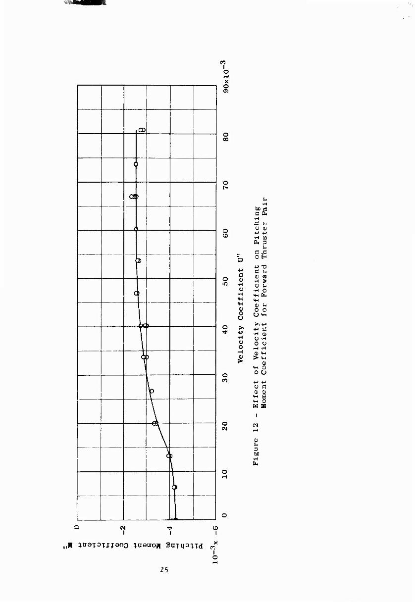
Figure 12 - Effect of Velocity Coefficient on Pitching Moment Coefficient for Forward Thruster Pair 25
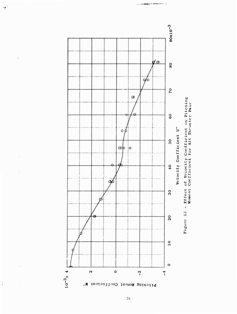
Figure 13 - Effect of Velocity Coefficient on Pitching Moment Coefficient for Aft Thruster Pair 26
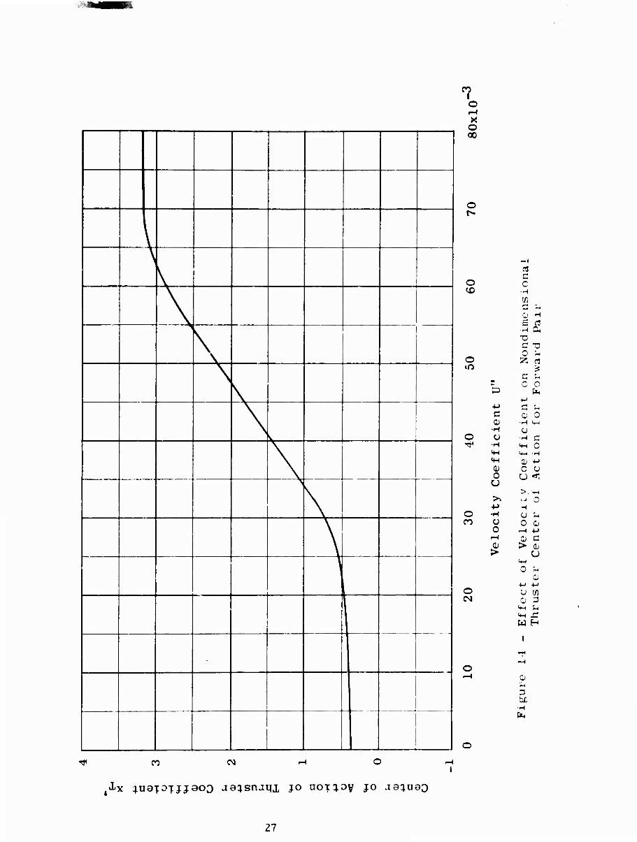
Figure 14 - Effect of Velocity Coefficient on Nondimensional Thruster Center of Action for Forward Pair 27
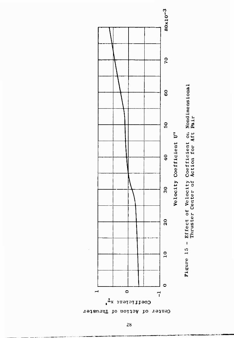
Figure 15 - Effect of Velocity Coefficient on Nondimensional Thruster Center of Action fcr Aft Pair 28
Figure 16 - Effect of Velocity Coefficient on Pitching Moment Coefficient for Forward and Ait Thruster Pairs Operating Together. 30
in
Page
Figure 17 - Effect of Velocity Coefficient on Longitudinal Force Coefficient for Forward Thruster Pair 31
Figure 18 - Effect of Velocity Coefficient on Longitudinal Force Coefficient for Aft Thruster Pair 32
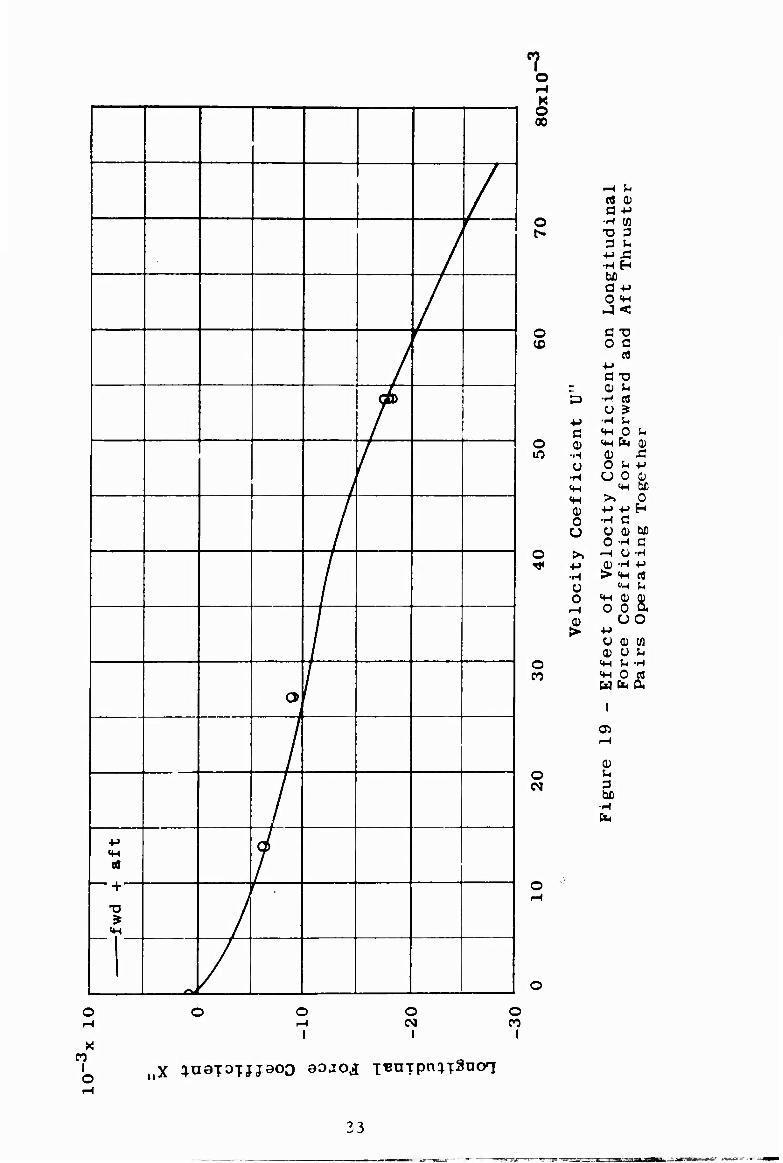
Figure 19 - Effect of Velocity Coefficient on Longitudinal Force for Forward and Aft Thruater Pairs Operating Together .... 33
Figure 20 - Effect of Velocity Coefficient on Lateral Force Coef- ficient for Forward Thruster Pair in Broadside Mode of Operation 35
Figure 21 - Effect of Velocity Coefficient on Yawing Moment Coef- ficient for Forward Thruster Pair in Broadside Mode of Operation 35
Figure 22 - Effect of Velocity Coefficient on Lateral Force Coef- ficient for Aft Thruster Pair in Broadside Mode of Operation 35
Figure 23 - Effect of Velocity Coefficient on Yawing Moment Coef- ficient for Aft Thruster Pair in Broadside Mode of Operation 35
Figure 24 - Elffect of Reynolds Number on Crossflow Drag Coefficient . . 36
Figure 25 - Effect of Sidewise Velocity on Lateral Force for Forward and Aft Thruster Pairs Operating Together 36
Figure 26 - Effect of Metacentric Height on Critical Speed. . , 38
Figure 27 - Effect of Critical Speed on RPM for Aft Thruster Pair 39
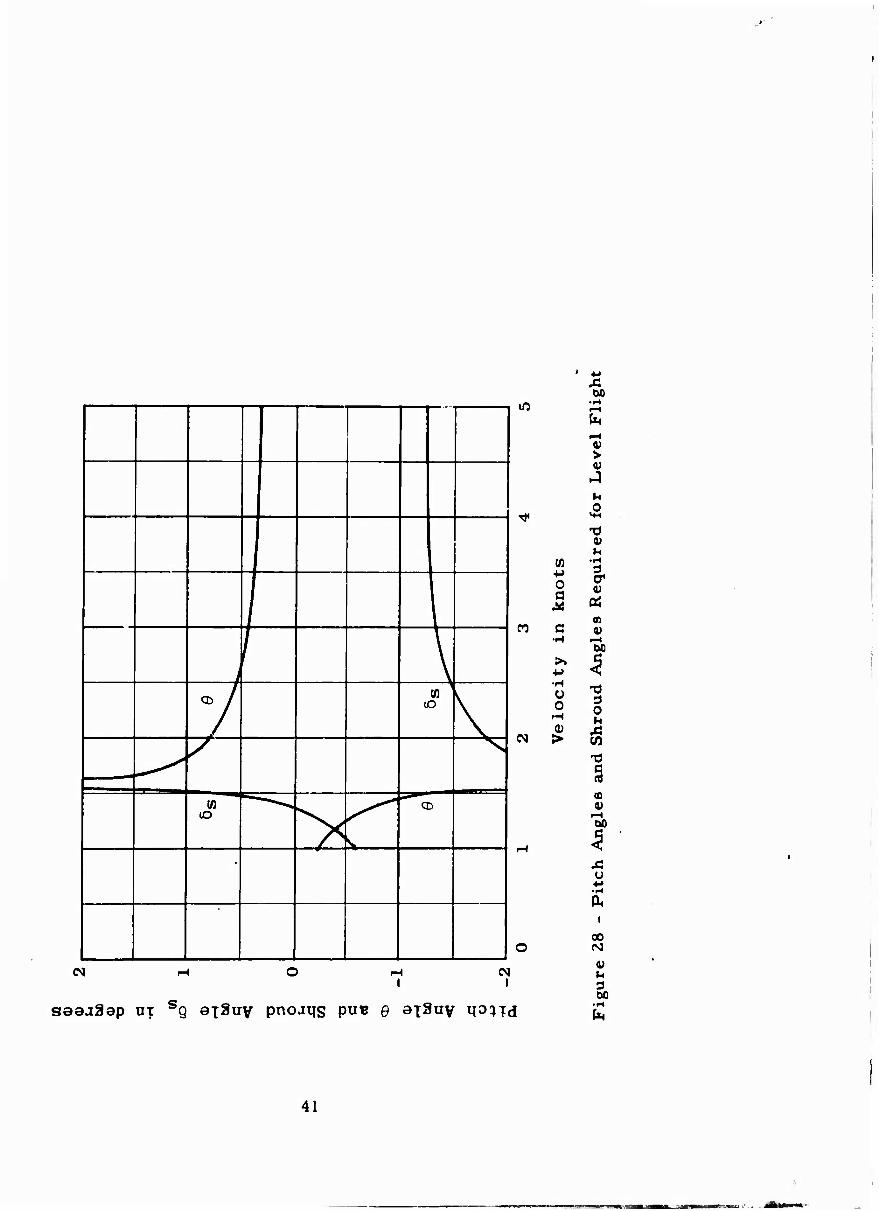
Figure 28 - Pitch Angles and Shroud Angles Required for Level Flight . . 41
Figure 29 - Variation of Normal Force Coefficient with Angle of Attack . . 44
Figure 30 - Variation of Pitching Moment Coefficient with Angle of Attack 45
Figure 31 - Variation of Longitudinal Force Coefficient with Reynolds Number 46
Figure 32 - Variation of Longitudinal Force Coefficient with Propulsion Ratio 47
IV
.'
Page
Figure 33 - Variation of Norma] Force Coefficient, with Stern- plane Angle 48
Figure 34 - Variation of Pitching Moment Coefficient with Stern- plane Angle 49
Figure 35 - Variation of Amplitudes of In-Phase Components of Normal Force Coefficient with Linear Acceleration Parameter 50
Figure 36 - Variation of Amplitudes of In-Phase Components of Normal Force Coefficient with Angular Acceleration Parameter 50
Figure 37 - Variation of Amplitudes of Quadrature Components of Normal Force Coefficient with Angular Velocity Parameter ' 50
Figure 38 - Variation of Lateral Force Coefficient with Angle of Drift 52
Figure 39 - Variation of Yawing Moment Coefficient with Angle of Drift 5 3
Figure 40 - Variation of Rolling Moment Coefficient with Angle of Drift 54
Figure 41 - Variation of Amplitudes of In-Phase Components of Lateral Force Coefficient with Linear Acceleration Parameter 55
Figure 42 - Variation of Amplitudes of In-Phase Components of Rolling Moment Coefficient with Linear Acceleration Parameter 55
Figure 43 - Variation of Amplitudes of In-Phase Components of Lateral Force Coefficient with Angular Acceleration Parameter 56
Figure 44 - Variation of Amplitudes of In-Phase Components of Rolling Moment Coefficient with Angular Acceleration Parameter 56
Figure 45 - Variation of Amplitudes of Quadrature Components of Lateral Force Coefficient with Angular Velocity Parameter 56
i
LIST OF TABLES
Page
Table 1 - Geometric Characteristics of Prototype 5
Table 2 - Nondimensional Stability and Control Coefficients and Prototype Constants 8
Table 3 - Nondimensional Stability Derivatives 10
Table 4 - Dimensional Angular Acceleration Parameter versus Time to Reach 5-Degree Pitch Angle Using 15-Degree Sternplane Angle for DSRV Scheme A 13
Table 5 - Force Coefficients and Torque Coefficients for Thruster Pair at Staudstill 14
Table 6 - Forces Delivered by Thruster Fairs at Maximum RPM (10 SHP) at Standstill 15
VI
I.
NOTATION
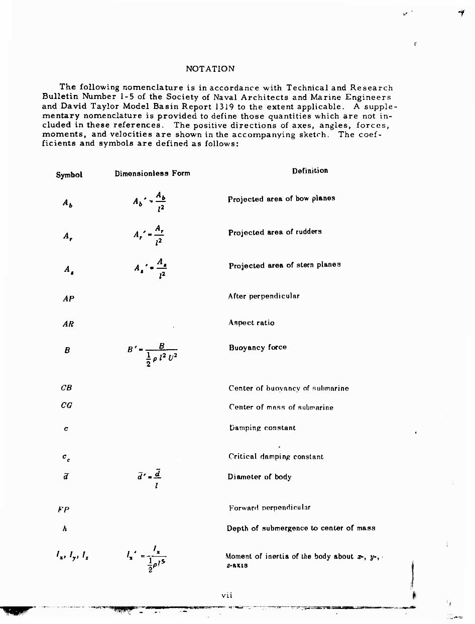
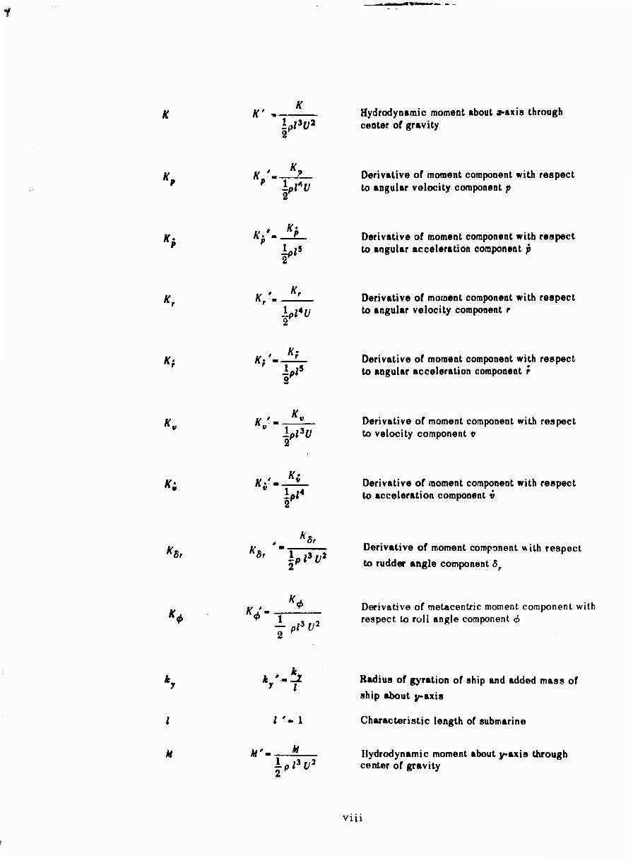
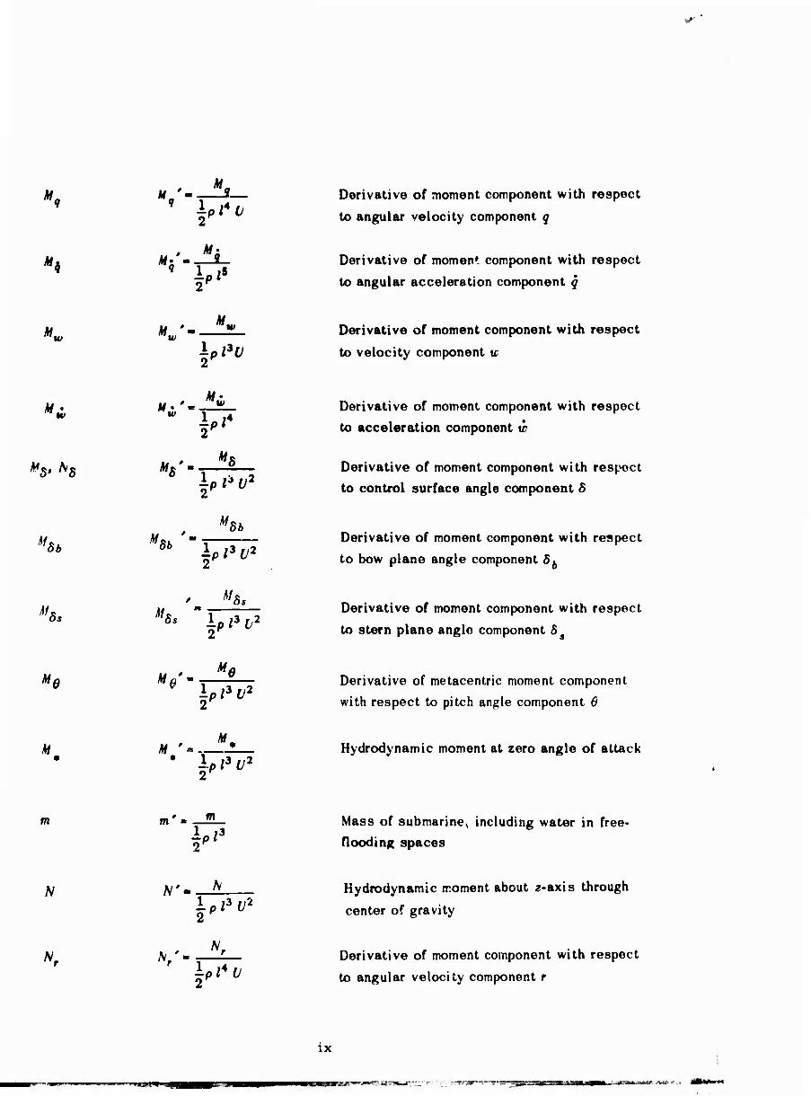
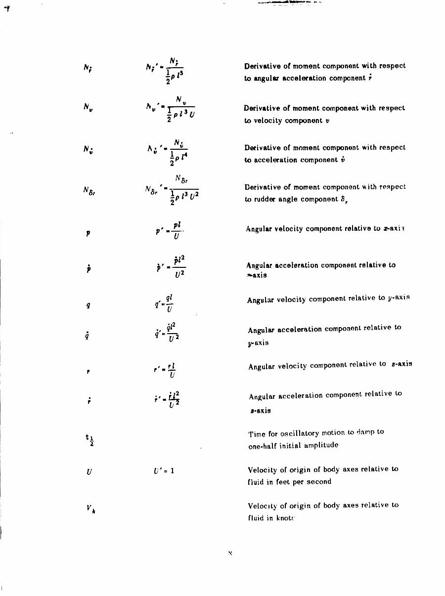
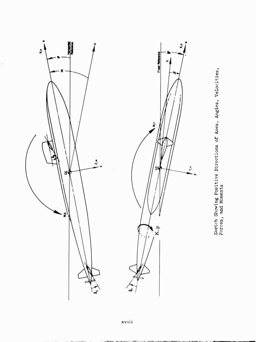
The following nomenclature is in accordance with Technical and Research Bulletin Number 1-5 of the Society of Naval Architects and Marine Engineers and David Taylor Model Basin Report 1319 to the extent applicable. A supple- mentary nomenclature is provided to define those quantities which are not in- cluded in these references. The positive directions of axes, angles, forces, moments, and velocities are shown in the accompanying sketch. The coef- ficients and symbols are defined as follows:
Symbol Dimensionless Form
A ' •
Definition
Projected area of bow planes
i2 Projected area of rudders
• f1
Projected area of stern planes
AP
AR
B B' B
±pl2V2
1
After perpendicular
Aspect ratio
Buoyancy force
CB
CG
Center of buovancv of submarine
Center of mass of submarine
Damping constant
d'-sL
Critical damping constant
Diameter of body
FP
h
Forward perpendicular
Depth of submergence to center of mass
',. ',. '. * 1 Ipl* Moment of inertia of the body about »•, y-, 2-axis
vn i
'r
'v
K' -m ^
l^'31"
K '- *, P
^^
H'-
K \ t. "r ■
¥v
«;'■
Ä '• . *« «!/
i"3"
*...'. . Ki
Hydrodynamic moment about a^-axis through center of gravity
X K 'm—Jt Derivative of moment component with respect 1 * 84 * to angular velocity component p
K. ^P m—— Derivative of moment component with respect p to angular acceleration component p
K Km—I— Derivative of moment component with respect
*5 r
to angular velocity component r
f(. Kf*m — Derivative of moment component with respect to angular acceleration component f
K K * m v Derivative of moment component with respect to velocity component v
K' K$'m—— Derivative of moment component with respect lp{4 to acceleration component v
v. r, «•? Derivative of moment component with respect "fir n8r l/,|3f/2 r K
2P to rudder angle component Sr
v '■ __L___ Derivative of metacentric moment component with ^ ^32 respect to roll angle component 0
2 P
k k k'~ -£ Radius of gyration of ship and added mass of
ship about y-axis
I i '• 1 Characteristic length of submarine
M M M'~ -—-—- Hydrodynamic moment about y-axis through
2 — pl3y2 center of gravity
vui
M,
*>
M.
H w
M5, ^5
M Sb
Mt
M e
M
m
N
N.
M ' - *. t yu
*■;
M f Mw
"w ip/'t/
M • ' , »i
mw
^
M*' «S mS I"'1"2
M8b
M8b
lp /3 ^2
/ "B. W5S ip/3^
^0 " &
Ipi'f
M ' .. ". • ip/3^
m' »>
f'3
\# - A
i"3"2
\ ' iv. "r
ip'4f
Derivative of moment component with respect
to angular velocity component q
Derivative of moment component with respect
to angular acceleration component q
Derivative of moment component with respect
to velocity component tc
Derivative of moment component with respect
to acceleration component w
Derivative of moment component with respect
to control surface angle component 5
Derivative of moment component with respect
to bow plane angle component 5fc
Derivative of moment component with respect
to stern plane angle component 5^
Derivative of metacentric moment component
with respect to pitch angle component 6
Hydrodynamic moment at zero angle of attack
Mass of submarine, including water in free-
flooding spaces
Hydrodynamic moment about 2-axis through
center of gravity
Derivative of moment component with respect
to angular velocity component r
IX
——— ^jm-^wm^rr^r <—~:. :vt'jm i—i -J j-j^-aa
*;
NV (V '-. V«
" ip'^
"i -A "8r
it
V v-'1
• Pi2
v u2
? n' ql
• 9'u*
r ''-'i • r
>"$
Derivative of moment component with respect
to angular acceleration component r
Derivative of moment component with respect
to velocity component v
Derivative of moment component with respect
to acceleration component v
Derivative of moment component with respect
to rudder angle component 5r
Angular velocity component relative to x-axh
Angular acceleration component relative to "»•axis
Angular velocity component relative to y-axis
Angular acceleration component relative to
y-axis
Angular velocity component relative to a-axis
Angular acceleration component relative to
8-axis
t^ Time for oscillatory motion to Hamp to
one-half initial amplitude
U t' = 1 Velocity of origin of body axes relative to
fluid in feet per second
Vk Velocity of origin of body axes relative to
fluid in knots
,—
V
V''
Component along y-axis of velocity of origin
of body relative to fluid
Component along y-axis of acceleration of
origin of body relative to fluid
w
to
V
xv ' * Hi \ V2
Component along a-axis of velocity 01 origin
of body axes relative to fluid
Component along 2-axis of acceleration of ori-
gin of body axes relative to fluid
XB' BB
X' lPl*U>
B I
"B -T 5B
Hydrodynamic longitudinal force, positive forward
The longitudinal axis, directed from the after
to the forward end of the submarine with origin
taken at the center of gravity
Coordinates of center of buoyancy with respect
to body axes
i
lpi^
■ * n T \^v
i * • — y-. r
^'4
/ y. V
ip'2f
y«' .. ^ ' V
I"1'
Hydrodynamic lateral for^e, positive to star-
board
Derivative of lateral force component with re
spect to angular velocity component r
Derivative of lateral force component with re-
spect to angular acceleration component t
Derivative of lateral force component with re-
spect to velocity component v
Derivative of lateral force component with re-
spect to acceleration component v
x:
y«* Z8 y5'- ig Derivative of force component with respect to
control surface angle component, 8
8r *' Ipi'v'
Derivative of lateral force component with re«
spect to rudder angle component Sr
Distance along the transverse axis, directed to
starboard with origin taken at center of gravity
Z' i,,^
Hydrodynamic normal force, positive downward
V-T Ipi'v Derivative of normal force component with re-
spect to angular velocity component q
Zi " lot
Derivative of normal force component with re-
spect to angular acceleration component q
w Z* w
" 1^ Derivative of normal force component with re-
spect to velocity component w
Z- Derivative of normal force component with re-
spect to acceleration component w
'8b '56
'5fc lpl*ü2
2
Derivative of normal force component with re-
spect to bow plane angle 5fc
'S» '5s lpl2U2
2K
Derivative of normal force component with re-
spect to stern-plane angle component S
Z ' * ip/2t/2
2K
Normal force at zero angle of attack
Distance along the normal axis, directed from
top to bottom (deck to keel), with origin taken
at center of gravity
xn
The angle of attack; the angle to the longitudi-
nal body axis from the projection into the prin-
cipal plane of symmetry of the velocity of the
origin of the body axes relative to the fluid,
positive in positive sense of rotation about
the y-axis
ß The drift or sideslip angle; the angle to the
principal plane of symmetry from the velocity
of the origin of the body axes relative to th.e .
fluid, positive in the positive sense of rota-
tion about the a-axis
S
S,
Angular displacement of a control surface
Angular displacement of bow planes, positivo
trailing edge down
5. Angular displacement of rudders, positive
trailing edge port
Angular displacement of stern planes, positive
trailing edge down
The angle of pitch; the angle of elevation of
the ar-axis positive bow up
p'-i Mas? doiisity of water
a. -a. — ' U
Roots of stability equation, i « 1, 2,
•A The angle of yaw
OJ
CO .
CL)
U Circular frequency of oscillation
(Ü ti> =
V Natural frequency of undamped oscil'ation
xiu
SUPPLEMENTARY NOMENCLATURE
Symbol Definition
Cnr, Crossflow drag coefficient based on projected lateral area.
d Diameter of thruster duct
K^I^I' Coefficient representing the nonlinear variation of K' with p' PIPI
K0 Torque coefficient for thruster pair (torque)/on2d5
K ' Coefficient representing the change in ^ the variation of K' versus q' with r'
K^ I^J' Coefficient representing the nonlinear variation of K' with v' v v
K^I^I' Coefficient representing the change in the variation of K' versus v' with w1 v w
K ' Coefficient representing the change in ^^ the variation of K' versus w' with p' it
M Hydrodynamic moment about y-axis due to a pair of thrusters in operation MT/|pa/d4£
Mi i ' Coefficient representing the change in UM
rr
vr
the variation of M' versus q' with 6 s
M ' Coefficient representing the change in " the variation of M' versus r1 with p'
M ' Coefficient representing the nonlinear variation of M' with r"
M ' Coefficient representing the change in ^ the variation of M' versus v1 with p'
M f Coefficient representing the change in the variation of M' versus v' with r'
xi v
M ' vv
Mi |w |q
Mi | w i
N ' pq
NM t
6r
Ni | 1 v| i
r
Nl 1 M i
V
N ' wv
Coefficient representing the nonlinear variation of M' with v'
Coefficient representing the change in the variation of M1 versus w' with q'
Coefficient representing the nonlinear variation of M' with w1
Coefficient representing the change in the variation of N' versus p' with q'
Coefficient representing the change in the variation of N' versus r1 with 5r
Coefficient representing the change in the variation of N' versus v' with r1
Coefficient representing the nonlinear variation of N1 with v'
Coefficient representing the change in the variation of N1 veisus w' with v'
n
n"
U
X • qq
X ' rP
X ' rr
X ' vr
Revolutions per second for thruster
P-atio of ordered speed to instantaneous speed of submarine
Shaft power of thruster pair
Velocity coefficient U/cüd
Hydrodynamic force along x-axis due to a pair of thrusters in operation XT/Wd4
Coefficient representing the nonlinear variation of X' with q'
Coefficient representing the change in the variation of X' versus r1 with p'
Coefficient representing the nonlinear variation of X1 with r'
Coefficient representing the change in the variation of X' versus v' with r'
xv
X ' Coefficient representing the nonlinear vv
ww
PIPI
v r
v|v|
wv
II
variation of X1 with v
X ' Coefficient representing the change in ^ the variation of X' versus w1 with q'
X ' Coefficient representing the nonlinear variation of X1 with w
X ' Coefficient representing the nonlinear variation of X' with 6
s
x ' Coefficient of longitudinal center of action for a pair of thrusters in operation, i.e. -MV
Y Hydrodynamic force along y-axis due to a pair of thrusters in operation YT/§pa?d4
Y j |' Coefficient representing the nonlinear variation of Y' with p'
Y ' Coefficient representing the change in ™ the variation of Y' versus p' with q1
Y| > ' Coefficient representing the change in ' the variation of Y' versus r' with 6r
Y^ | ^ |' Coefficient representing the change in the variation of Y' versus v' with r'
Y^I^I' Coefficient representing the nonlinear variation of Y' with v'
Y ' Coefficient representing the change in " the variation of Y' versus w' with p'
Y ' Co fficient representing the change in the variation of Y! versus w' with v'
Z Hydrodynamic force along z-axis due to a pair of thrusters in operation ZTAoüJ2d4
Zi | ' Coefficient representing the change in '"' the variation of Z' versus q' with 6
Z ' Coefficient representing the change in P the variation of Z' versus r' with p1
xvi
Z ' Coefficient representing the nonlinear variation of Z' with r'
Z ' Coefficient representing the change in the variation of Z' versus v1 with p1
Z ' Coefficient representing the change in the variation of Z' versus v1 with r'
Z ' Coefficient representing the nonlinear vv 6
Subscripts
variation of Z' with v
Z | i1 Coefficient representing the change in '^' the variation of Z1 versus w' with q'
Z I i' Coefficient representinc the nonlinear w w1 r b variation of Z' with w'
0) Thruster frequency in radians per second
IAI Absolute value of A
Indicates value for a pair of thrusters
xvu
—'-«r—'—■
O
0) >
to
o en Ö o •H
o 0) f-.
Q
OJ >
•r-l
■H W o
10 -P c a
b0 O a s
•H
o ß
X o
XV111
ABSTRACT
i Stability and control coefficients, derived from model tests using the
DTMB Planar-Motion-Mechanism System and supplemented by analytical estimates, are presented for use in detailed simulation studies of the motions of a preliminary design for the Deep Submergence Rescue Vessel (DSRV) in six degrees of freedom. Analyses are made to evaluate the inherent dynamic stability and control effectiveness characteristics of the vehicle for motions confined to either the vertical or horizontal plane. The results of a special investigation to determine effects of forward speed and broadside motion on the performance of the thrusters are also presented and discussed.
INTRODUCTION
The Special Projects Office requested the David Taylor Model Bajiin to prepare and execute a program of captive-model tests to determine the stability and control characteristics of a preliminary design for the Deep Submergence Rescue Vessel (DSRV). l The primary purpose of this program was to provide all of the hydrodynamic coefficients required for conducting detailed simulation studies of the motions of the DSRV in six degrees of freedo including hovering and pivoting modes as well as cruising modes. In addition, the coefficients were required to serve as a basis for the design of the auto- matic control system.
The DSRV is a small submersible designed to rescue personnel from disabled submarines and to transfer them to another submarine. The concept of the subject design entail, the use of ducted thrusters to provide the pre- cision control necessary for the mating operation in conjunction with an all- movable shroud for control at the higher speeds associated with search and transport.
To carry out the aforementioned objectives, tl • David Taylor Model Basin constructed a one-third scale model and carried out a comprehensive program of tests on the DTMB Planar-Motion-Mechanism System. This program in- cluded not only the types of stability and control tests performed on conventional submarines but a special group of experiments to determine the control forces due to the thrusters. An oral presentation of some of the results of these tests was made at the David Taylor Model Basin to the representatives of the Special Projects Office in March 1966.
This report describes the prototype and model, outlines the test procedures and presents the final results of the test program. To facilitate the simulation studies, a complete set of coefficients to be used in conjunction with the DTMB submarine equations of motion is provided. In addition, an analysis is made of the inherent stability and control characteristics including the determination of stability indices, neutral angles, critical speed, and control effectiveness of both the movable shroud and the thruster system.
1 References are listed on page 57.
DESCRIPTION OF PROTOTYPE AND MODEL
The configuration of the subject design for the Deep Submergence Rescue Vessel, designated hereinafter as DSRV Scieme A, is shown in Figure 1 and by model photograph in Figure 2. The principal dimensions of the prototype and model are given in Table 1. The basic hull is a body of revolution 43. 25 feet in length and 8.0 feet in diameter. Superimposed on the basic hull is an observation dome on the top and an escape hatch on the bottom. A tail as- sembly consisting of a shroud and single screw propeller is provided for pro- pulsion, control, and dynamic stability in forward flight. Forward and aft pairs of transverse thrusters, each unit consisting of a tube or duct enclosing a screw propeller, are provided for control in hovering, pivoting, and broad- side motion. These thruster units are referred to by N nbers 1 through 4 in sequence from the bow to the stern.
The subject design is represented by Model 5036, a 14. 42-foot long model constructed of mahogany. It should be emphasized that, to expedite the test program, the simplified thrust units rather than the refined TMB design units were used for the stability and control tests. These employed commercial outboard motor right angle drive urits which necessitated the use of relatively large propeller hubs and support struts. As the result, the propeller hub- duct diameter ratio was about 0,42 compared with the 0. 27 contemplated for the TMB design.
TEST APPARATUS AND PROCEDURE
The experiments were conducted in the deep-water basin on Towing Carriage 2 using the DTMB Planar-Motion-Mechanism System described in Reference 2. The model wac supported by two towing struts with support points spaced 4. 5 feet apart ( ±2. 25 feet from the reference point, or prototype center of gravity location). The longitudinal, lateral, and normal forces and pitching, yawing, and rolling moments were measured by means of two sets of gages inside the model, one set at each strut. The horizontal plane was simulated by relocating the dome by rotating it through 90 degrees about the longitudinal axis. The escape hatch, however, was not relocated, but instead was removed and a cover plate attached in its place.
The experimental program included all of the types of static stability and control tests and oscillator tests that are normally carried out for submarines.2 In addition, a special group of tests was conducted to determine the coefficients required to simulate the action of the thrusters in various modes of motion.
The static stability and control tests were conducted at a speed of 6 knots (corresponding to a Reynolds number of 1. 3 x 10 based on the length of the submarine). The angles of attack and drift in this group of tests were carried out to ±18 degrees. The maximum angle on the all-movable shroud was 15 degrees both in the sternplane and rudder modes.
The oscillator tests were conducted over a range of speeds from 4.0 to 6.0 knots, inclusive.
2
f
Figure 2 - Photographs of Model of DSRV Scheme A
4
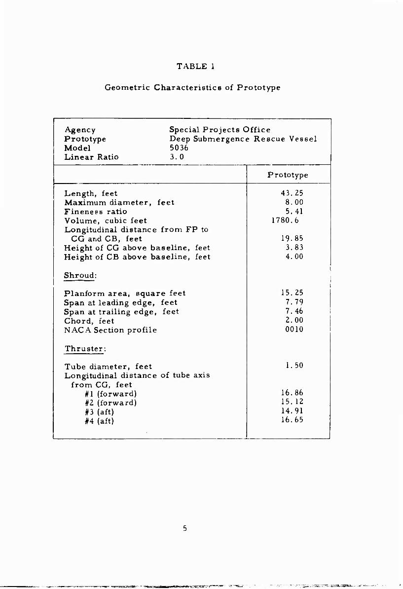
TABLE 1
Geometric Characteristics of Prototype
Agency Special Projects Office Prototype Deep Submergence Rescue Vessel Model 5036 Linear Ratio 3. 0
Prototype
Length, feet 43.25 Maximum diameter, feet 8.00 Fineness ratio 5.41 Volume, cubic feet 1780.6 Longitudinal distance from FP to
CG and CB, feet 19.85 Height of CG above baseline, feet 3.83 Height of CB above baseline, feet 4.00
Shroud: 1
Planform area, square feet 15.25 1 Span at leading edge, feet 7.79 Span at trailing edge, feet 7.46 ! Chord, feet 2.00 1 NACA Section profile 0010 i
Thruster:
Tube diameter, feet 1.50 Longitudinal distance of tube axis
from CG, feet #1 (forward) 16.86 ! #2 (forward) 15.12 | #3 (aft) 14.91 i #4 (aft) 16.65 1
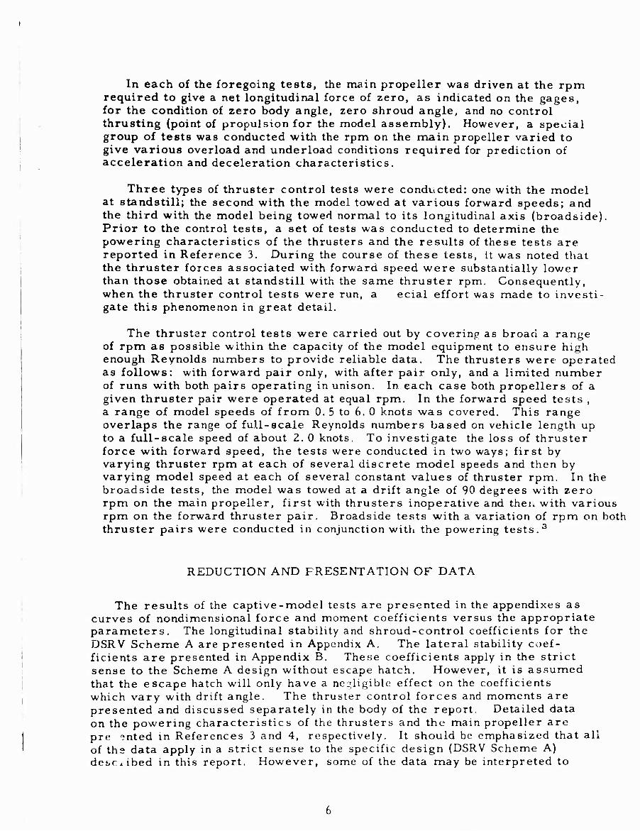
In each of the foregoing tests, the main propeller was driven at the rpm required to give a net longitudinal force of zero, as indicated on the gages, for the condition of zero body angle, zero shroud angle, and no control thrusting (point of propulsion for the model assembly). However, a special group of tests was conducted with the rpm on the main propeller varied to give various overload and underload conditions required for prediction of acceleration and deceleration characteristics.
Three types of thruster control tests were conducted: one with the model at standstill; the second with the model towed at various forward speeds; and the third with the model being towed normal to its longitudinal axis (broadside). Prior to the control tests, a set of tests was conducted to determine the powering characteristics of the thrusters and the results of these tests are reported in Reference 3. During the course of these tests, it was noted that the thruster forces associated with forward speed were substantially lower than those obtained at standstill with the same thruster rpm. Consequently, when the thruster control tests were run, a ecial effort was made to investi- gate this pthenomenon in great detail.
The thruster control tests were carried out by covering as broad a range of rpm as possible within the capacity of the model equipment to ensure high enough Reynolds numbers to provide reliable data. The thrusters were operated as follows: with forward pair only, with after pair only, and a limited number of runs with both pairs operating in unison. In each case both propellers of a given thruster pair were operated at equal rpm. In the forward speed tests , a range of model speeds of from 0. 5 to 6. 0 knots was covered. This range overlaps the range of full-scale Reynolds numbers based on vehicle length up to a full-scale speed of about 2. 0 knots. To investigate the loss of thruster force with forward speed, the tests were conducted in two ways; first by varying thruster rpm at each of several discrete model speeds and then by varying model speed at each of several constant values of thruster rpm. In the broadside tests, the model was towed at a drift angle of 90 degrees with zero rpm on the main propeller, first with thrusters inoperative and theu with various rpm on the forward thruster pair. Broadside tests with a variation of rpm on both thruster pairs were conducted in conjunction with the powering tests.3
REDUCTION AND PRESENTATION OF DATA
The results of the captive-model tests are presented in the appendixes as curves of nondimensional force and moment coefficients versus the appropriate parameters. The longitudinal stability and shroud-control coefficients for the DSRV Scheme A are presented in Appendix A. The lateral stability coef- ficients are presented in Appendix B. Theye coefficients apply in the strict sense to the Scheme A design without escape hatch. However, it is assumed that the escape hatch will only have a negligible effect on the coefficients which vary with drift angle. The thruster control forces and moments are presented and discussed separately in the body of the report. Detailed data on the powering characteristics of the thrusters and the main propeller are pre onted in References 3 and 4, respectively. It should be emphasized that all of the data apply in a strict sense to the specific design (DSRV Scheme A) de^Ciibed in this report. However, some of the data may be interpreted to
explore other design possibilities within the same design concept.
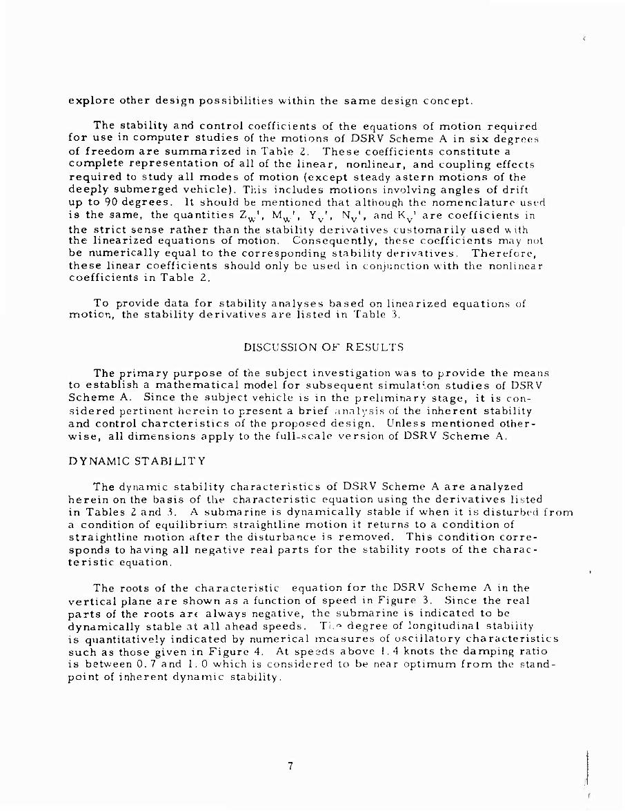
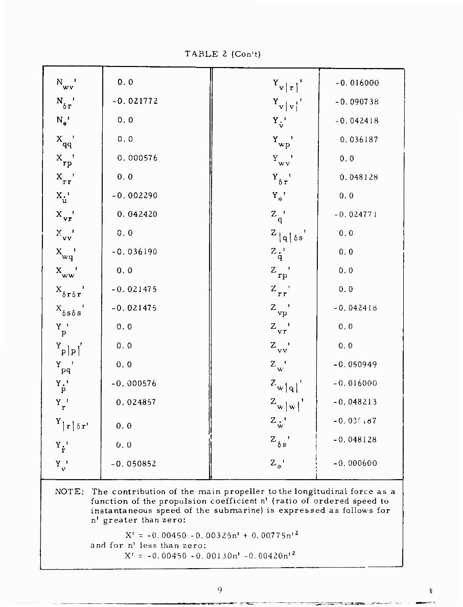
The stability and control coefficients of the equations of motion required for use in computer studies of the motions of DSRV Scheme A in six degrees of freedom are summarized in Table 2. These coefficients constitute a complete representation of all of the linear, nonlinear, and coupling effects required to study all modes of motion (except steady astern motions of the deeply submerged vehicle). This includes motions involving angles of drift up to 90 degrees. It should be mentioned that although the nomenclature used is the same, the quantities Zw', M^', Y^, Nv\ and K^ are coefficients in the strict sense rather than the stability derivatives customarily used with the linearized equations of motion. Consequently, these coefficients may nut be numerically equal to the corresponding stability derivatives. Therefore, these linear coefficients should only be used in conjunction with the nonlinear coefficients in Table Z.
To provide data for stability analyses based on linearized equations of motion, the stability derivatives are listed in Table 3,
DISCUSSION OF RESULTS
The primary purpose of the subject investigation was to provide the means to establish a mathematical model for subsequent simulation studies of DSRV Scheme A. Since the subject vehicle is in the preliminary stage, it is con- sidered pertinent herein to present a brief analysis of the inherent stability and control charcteristics of the proposed design. Unless mentioned other- wise, all dimensions apply to the full-scale version of DSRV Scheme A.
DYNAMIC STABILITY
The dynamic stability characteristics of DSRV Scheme A are analyzed herein on the basis of the characteristic equation using the derivatives listed in Tables 2 and 3. A submarine is dynamically stable if when it is disturbed from a condition of equilibrium straightline motion it returns to a condition of straightline motion after the disturbance is removed. This condition corre- sponds to having all negative real parts for the stability roots of the charac- teristic equation.
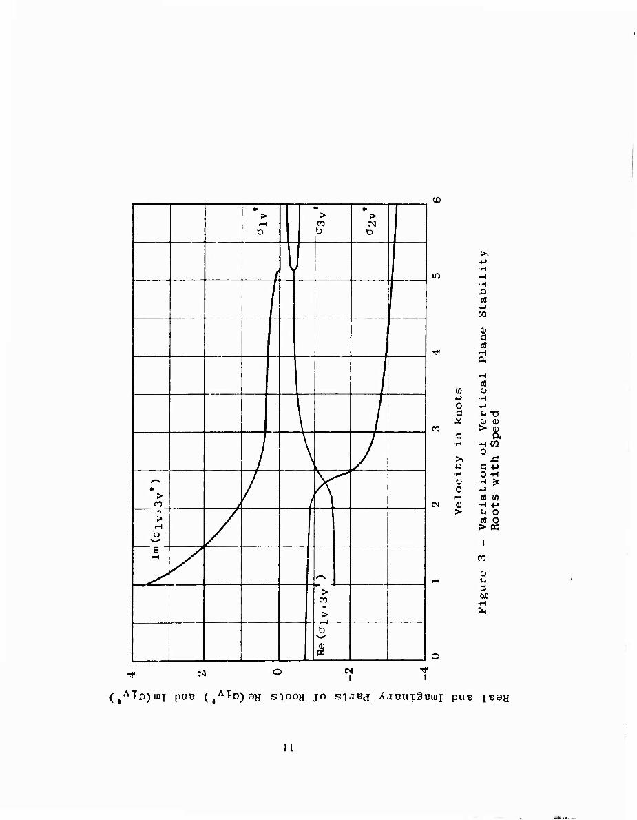
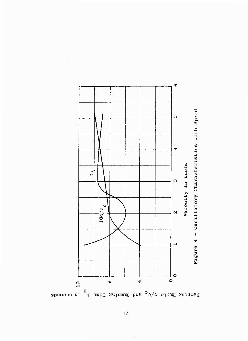
The roots of the characteristic equation for the DSRV Scheme A in the vertical plane are shown as a function of speed in Figure 3. Since the real parts of the roots art always negative, the submarine is indicated to be dynamically stable at all ahead speeds. Tl.« degree of longitudinal stability is quantitatively indicated by numerical measures of oscillatory characteristics such as those given in Figure 4. At speeds above 1.4 knots the damping ratio is between 0. 7 and 1.0 which is considered to be near optimum from the stand- point of inherent dynamic stability.
f
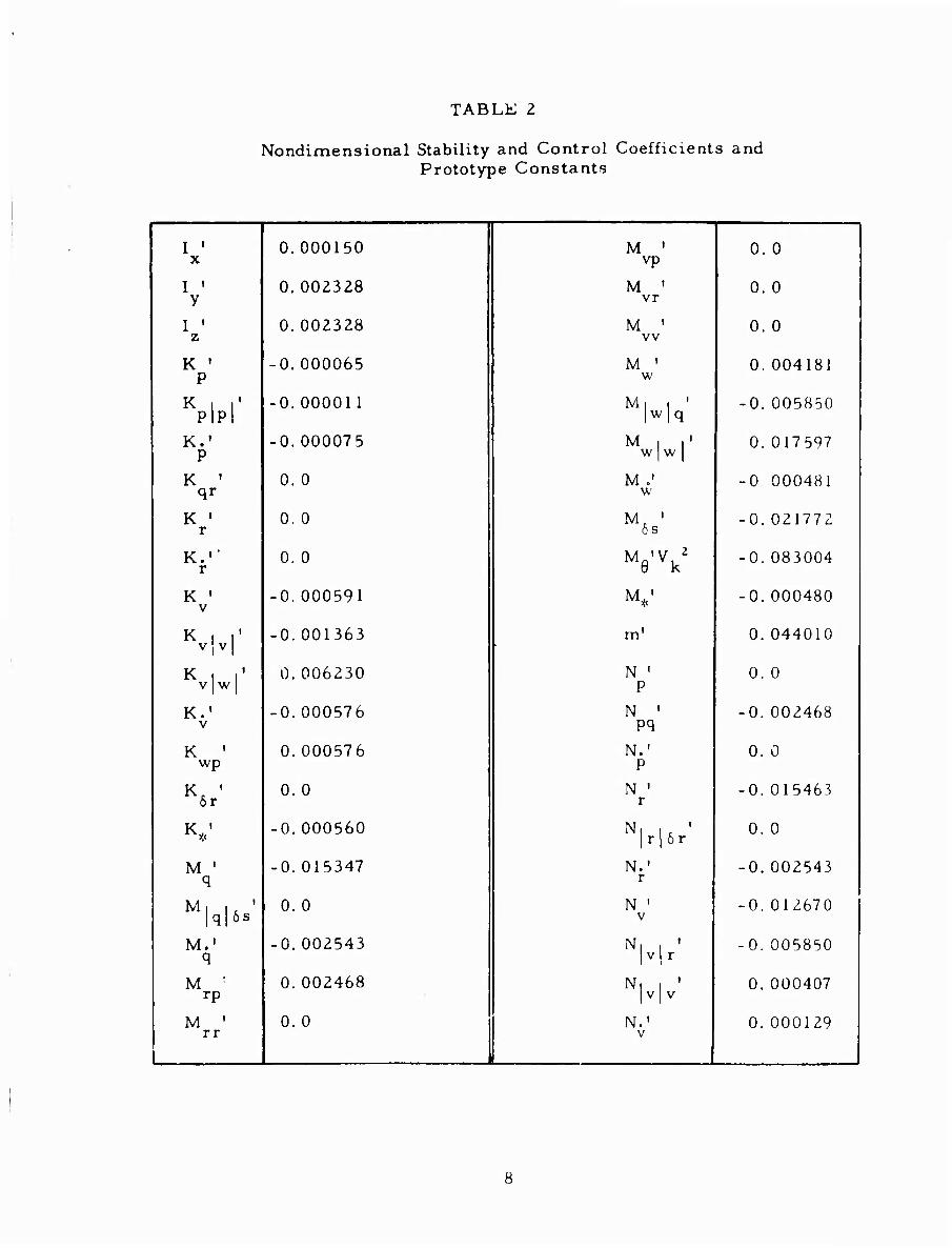
TABLE 2
Nondimensional Stability and Control Coefficients and Prototype Constants
I • x
0.000150 j M ' vp
0. 0
1 y 0.002328 1 | M ' vr i o. o
I ' 'l 0.002328 i M ' vv
0. 0
K ' P
-0.000065 | i M ' 1 w 0.004181
i K i r PIPI -0.000011 i Mi | '
' 1w 1 ^ -0.005850
K.1
P -0.000075 j Mil'
! W | W j 0.017597 |
K ' qr
0. 0 | M ,' 1 w -0 000481
K ' r
o. o ! 1 6s -0.021772
i r 0. 0 | I M 'V 2
! Me vk -0.083004
K ' V
-0.000591 M,' -0.000480
1 K i r ! v Iv 1 -0.001363 j m' 0.044010
K i i' v w 0.006230 1 N '
P 0. 0 j
i K.' i v
-0.000576 N ' -0.002468
K ' wp
0.000576 N.' ! p
0. 0 !
! 6r 0. 0 1 N ' r
-0.015463 j
Ky;
-0.000560 ! Nl U ' i 1r 16r 0. 0 |
j M ' 1 ^ -0.015347 N.'
r -0.002543 |
M, . ' jq|6s 0. 0 | N '
1 v -0.012670 j
M.' 1 q -0.002543 I N| | '
1 1 v 1 r -0.005850
M :
rP 0.002468 i N| , '
1 1 v 1 v 0.000407 |
M ' rr
0. 0 N.' V
0.000129 1
TA.BLE 2 (Con't)
N ' wv
6r
X ' qq
x ' rp
x ' rr
X.1 u
X ' vr
X ' vv
X ' wq
X ' ww
6r6r
6s6s
Y ' P
YP1PI Y ' pq
Y.' P
Y ' r
rjör'
Y.' r
Y ' v
0. 0
-0.021772
0. 0
0. 0
0. 000576
0. 0
-0.002290
0.042420
0. 0
■0.036190
0. 0
•0.021475
•0.021475
0. 0
0. 0
0. 0
0. 000576
0. 024857
0. 0
0. 0
0. 050852
Y i i' v | r j
Y 1 >' V j V j
Y.' V
Y ' wp
Y ' wv
6r
Y*'
Z ' q
Zl u |q| 6s
Z,' q
rp
rr
vp
vr
vv
Z ' w
w|q|
Z I i' w w
Z . ' w
6s
7 '
-0.016000
-0.090738
-0.042418
0.036187
0. 0
0. 048128
0.0
-0. 02477 1
0.0
0.0
0. 0
0.0
-0. 042418
0.0
0.0
-0. 050949
-0. 016000
-0.048213
-0.03-/xö7
-0. 048128
-0.000600
NOTE: The contribution of the main propeller to the longitudinal force as a function of the propulsion coefficient n' (ratio of ordered speed to instantaneous speed of the submarine) is expressed as follows for n' greater than zero:
X' = -0.00450 -0.00325^ + 0.00775n,2
and for n1 less than zero: X1 = -0.00450 -O.OOliGn' -0.00420n|2
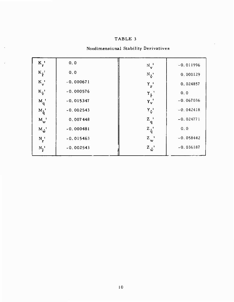
TABLE 3
Nondimensional Stability Derivatives
K ' r
0.0 N '
V -0.011996
Kf! 0.0 N.1
V 0.000129
K ' V
-0.000671 Y ' r
0.024857
K.' V
-0.000576 Y. ' r
0.0
M ' q
-0.015347 Y ' 1 V -0. 067036
M.' q
-0.002543 Y.' V
-0.042418
M ' w
0.007 448 Z ' q
-0. 024771
M.' w
-0.000481 Z.' q
0. 0
N ' r -0.015463 Z ' w
-0.058442
N.« r
-0.002543 Z .' w
-0. 036187
10
* i i > 1 .-I 1 D 1
>• CO Ü
• 1 >
(N D
A 1
j
|
\ /
/ J 1 • i > i «
1 **
i > o
/ / r M
j j
1 r*
i 1
i r> >
1
11^
<0
m
CO
(N
C>1 I I
CO ■M 0 a x a
•rH
>. ■M •H Ü O rH
>
■M •H
« CO
o a ea
rH
e3 V
•H ■M
>g< «H 73 O
C -M 0 -H •H ^ 4-> (0 CO
•H -p ^ O
£S I
a» 3
(J^TD)^! PUB (,^^0)911 s^ooy jo s^jBd AJBUT3BIUI PUB lean
11
( |
'\
1 +J ■\j 1 M ̂
1
A \
1
1
o r—1 V f ^
/\
<£>
in
en
IN
0 a x a •H
>. +J •H Ü 0
0)
CO
X! ■P ■H ? w Ü •H -M W •rt e *-* 0) -p ü c« ^
x: u
>» u o ■M C5
■H O
S
(1) U
a •H
(N 00
SpUOOaS UT :1 9UIT.L äUTdUIBQ PUB Do/D OT^ÜH SUTCllUBa
12
In the horizontal plane the stability roots are independent of forward speed. For DSRV Scheme A the stability root is a! = -0.5 Tnis indicates that the vehicle will be inherently dynamically stable in the horizontal plane.
SHROUD CONTROL EFFECTIVENESS
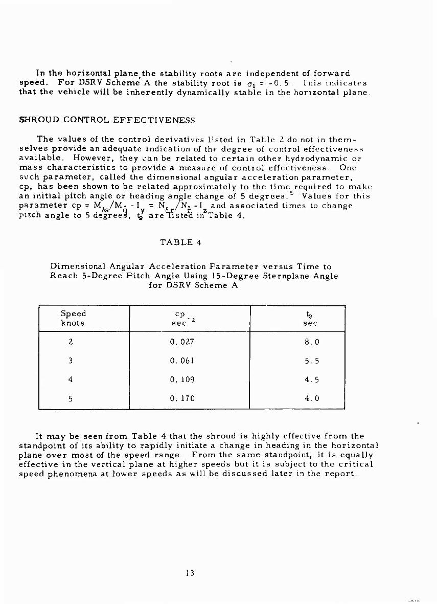
The values of the control derivatives Tsted in Table 2 do not in them- selves provide an adequate indication of the degree of control effectiveness available. However, they ^an be related to certain other hydrodynamic or mass characteristics to provide a measure of contiol effectiveness. One such parameter, called the dimensional angular acceleration parameter, cp, has been shown to be related approximately to the time required to make an initial pitch angle or heading angle change of 5 degrees.5 Values for this parameter cp = M /M. -I = N. /N. -I and associated times to change pitch angle to 5 degrees, tg are listed in Table 4.
TABLE 4
Dimensional Angular Acceleration Parameter versus Time to Reach 5-Degree Pitch Angle Using 15-Degree Sternplane Angle
for DSRV Scheme A
Speed knots
CP^ sec sec
2 0. 027 8.0
3 0. 061 5. 5
4 0. 109 4.5
5 0. 170 4.0
It may be seen from Table 4 that the shroud is highly effective from the standpoint of its ability to rapidly initiate a change in heading in the horizontal plane over most of the speed range. From the same standpoint, it is equally effective in the vertical plane at higher speeds but it is subject to the critical speed phenomena at lower speeds as will be discussed later in the report.
13
THRUSTER EFFECTIVENESS
The effectiveness of the thrusters in various modes including forward speed, broadside motion, and standstill is discussed herein. Unless stated otherwise, the thruster forces (normal force Z, lateral force Y, and longitudinal force X) are "delivered forces," or incremental forces produced by the thrusters as op- posed to a thrust exerted at the propeller shaft. It should be emphasized that the force and moment coefficients as well as the propeller torque coefficients contained in this section of the report are strictly applicable to the simplified thruster design used in the tests. It may be reasonably anticipated that some- what higher delivered forces for any given horsepower will be obtained with the refined TMB design. However, it is believed that the effects shown for the various modes of operation on thruster performance will be relatively the same for the new design. Furthermore, the following assumptions have been made concerning the thruster data contained in this report:
1. The forward pair (Numbers 1 and 2) or the aft pair (Numbers 3 and 4) always operate at the same rpm.
2. The torque coefficient for the forward pair is the same as the torque coefficient for the aft pair at standstill.
3. The designed maximum shaft horsepower (shp for each thruster pair) is 10.
Standstill Mode
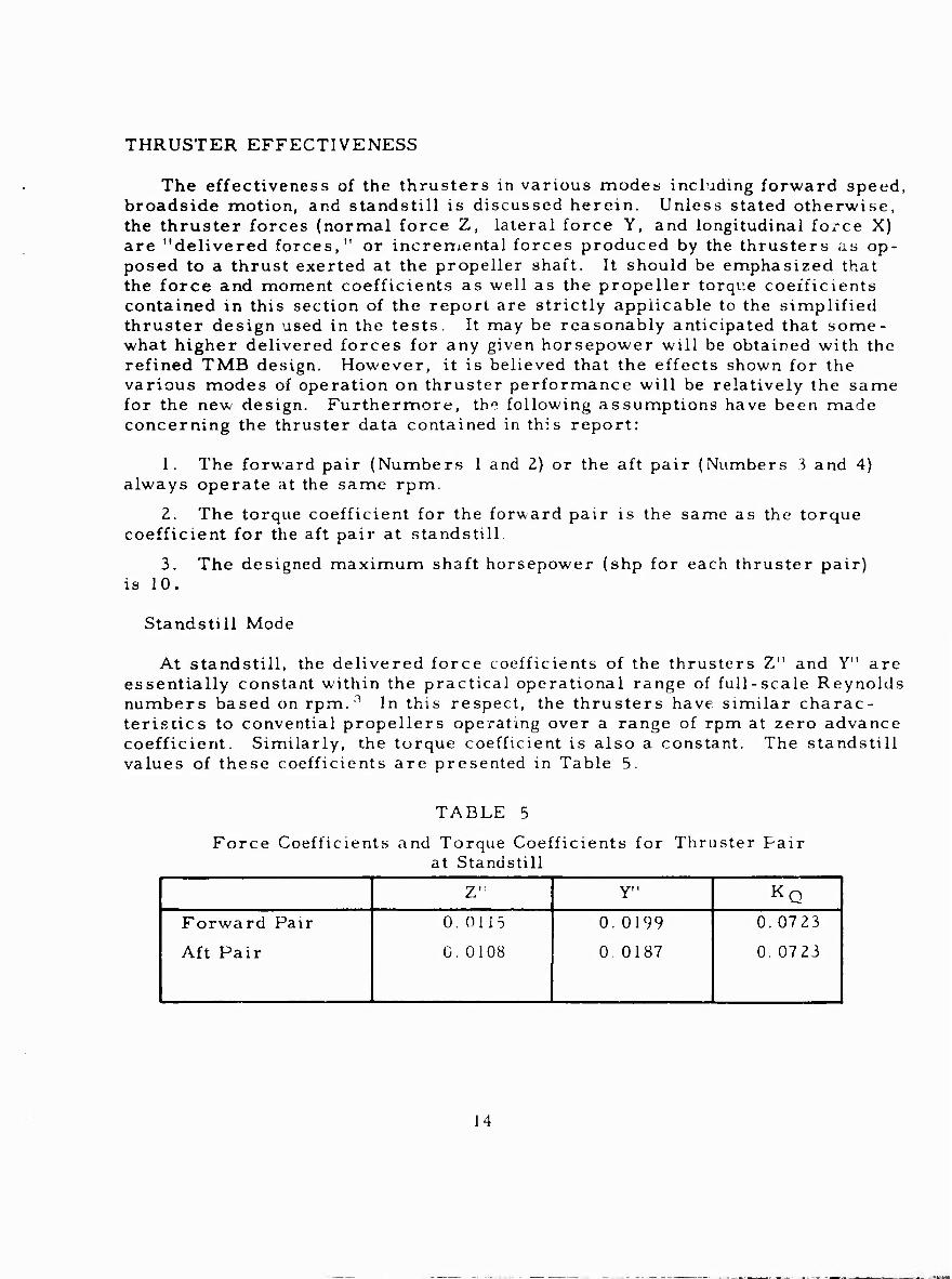
At standstill, the delivered force coefficients of the thrusters Z" and Y" are essentially constant within the practical operational range of full-scale Reynolds numbers based on rpm.3 In this respect, the thrusters have similar charac- teristics to convential propellers operating over a range of rpm at zero advance coefficient. Similarly, the torque coefficient is also a constant. The standstill values of these coefficients are presented in Table 5.
TABLE 5
Force Coefficients and Torque Coefficients for Thruster Pair at Standstill
Z" Y" KQ
! Forward Pair
Aft Pair
0.0115
0. 0108
0.0199
0. 0187
0.0723
0.0723
14
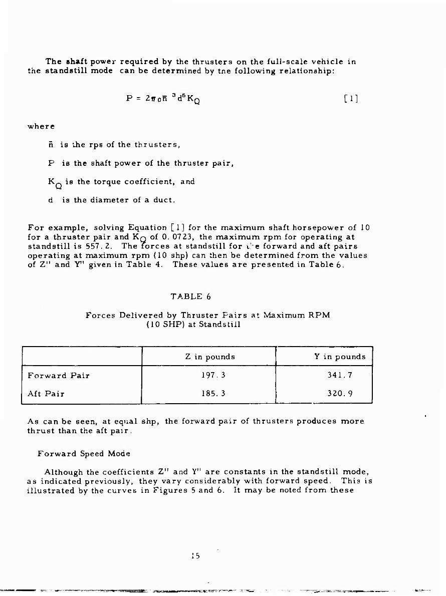
The shaft power required by the thrusters on the full-scale vehicle in the standstill mode can be determined by tne following relationship:
_ 3 ,5 P = Ztron 0d0K Q [1]
where
n is ihe rps of the thrusters,
P is the shaft power of the thruster pair,
K„ is the torque coefficient, and
d is the diameter of a duct.
For example, solving Equation [1] for the maximum shaft horsepower of 10 for a thruster pair and KQ of 0. 07 23, the maximum rpm for operating at standstill is 557. 2. The forces at standstill for Ce forward and aft pairs operating at maximum rpm (10 shp) can then be determined from the values of Z" and Y1' given in Table 4. These values are presented in Table 6.
TABLE 6
Forces Delivered by Thruster Fairs at Maximum RPM (10 SHP) at Standstill
Z in pounds Y in pounds
Forward Pair
Aft Pair
197. 3
185. 3
341.7 |
320.9 1
As can be seen, at equal shp, the forward pair of thrusters produces more thrust than the aft pair.
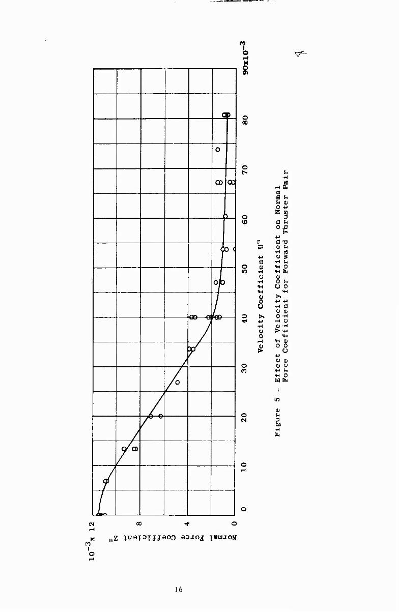
Forward Speed Mode
Although the coefficients Z" and Y" are constants in the standstill mode, as indicated previously, they vary considerably with forward speed. This is illustrated by the curves in Figures 5 and 6. It may be noted from these
15
~»^r «umiiiip i.»i ■ j^Bta« [■■fLilll I»1"
•^
(9
0
00 OCJ 1
>
O) d
ojo
7 / /
/
/
/
/
Q/CD
/ i
o 00
o
o to
o m
a 0)
o u
•H O o r-l
o
o
o r-i
rH
X
o
00 T}* o
fi e ^ O -P 2 0]
3 a t. O X!
h a TJ a; u
ü •H U «H 0
0 t- u o
8 ^ a
o -H rH O (D •(-(
0
•t-> o
<H
0 u 0) Ü S-. o
W h
I
in
0)
3
•H fa
16
CO I o
0>
0 o 00
0
o
o CO
o
o
o CO
b a 0)
•H
•H «H <M 0) o u >.
•M •H O o
1-1
>
0 0 (9 S- S -H
0 (2 35
a a) o ■»-.
a t, .2^
nr id >
o 0
Velo
cit
y
Co
eff
i(
rtcie
nt
fo
r A
ft
i 1 a >
H n
] <H CO 0 0
oc y Sff
eci
Forc
e
'
UJJ\ -D
o
<£> i U 3
■H
/
o h
0 &°
o
o
/ 1 1
i
1 (N
CO I o
oo ^ O
„Z ^uaT3TJjaoo BOJOJ T«UIJOK
17
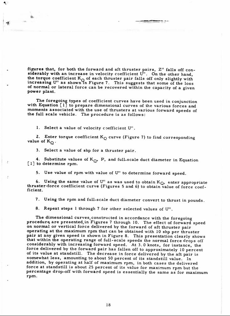
f i g u r e s tha t , f o r both the f o r w a r d and af t t h r u s t e r p a i r s , Z" f a l l s off con-s i d e r a b l y wi th an i n c r e a s e in ve loc i ty c o e f f i c i e n t U" . On the o t h e r hand, the t o r q u e c o e f f i c i e n t KQ of each t h r u s t e r p a i r f a l l s off only s l igh t ly wi th i n c r e a s i n g U" a s shown in F i g u r e 7. This s u g g e s t s that s o m e of the l o s s of n o r m a l o r l a t e r a l f o r c e can be r e c o v e r e d wi th in the c a p a c i t y of a g iven p o w e r p l a n t .
The f o r e g o i n g t y p e s of c o e f f i c i e n t c u r v e s have been used in con junc t ion wi th Equa t ion [ 1 ] to p r e p a r e d i m e n s i o n a l c u r v e s of the v a r i o u s f o r c e s and m o m e n t s a s s o c i a t e d wi th the u s e of t h r u s t e r s a t v a r i o u s f o r w a r d s p e e d s of the f u l l s c a l e v e h i c l e . The p r o c e d u r e is a s fo l lows :
1. Se l ec t a va lue of ve loc i ty coe f f i c i en t U" .
2. E n t e r t o r q u e c o e f f i c i e n t KQ c u r v e ( F i g u r e 7) to f ind c o r r e s p o n d i n g va lue of KQ .
3. Se l ec t a va lue of shp f o r a t h r u s t e r p a i r .
4. Subs t i t u t e v a l u e s of K Q , P , and f u l l - s c a l e duc t d i a m e t e r in Equa t ion [ 1 ] to d e t e r m i n e r p m .
5. Use va lue of r p m with va lue of U" to d e t e r m i n e f o r w a r d speed .
6. Us ing the s a m e value of U" a s w a s u sed to obta in KQ, e n t e r a p p r o p r i a t e t h r u s t e r - f o r c e c o e f f i c i e n t c u r v e ( F i g u r e s 5 and 6) to ob ta in va lue of f o r c e c o e f -f i c i e n t .
7. Us ing the r p m and f u l l - s c a l e duc t d i a m e t e r c o n v e r t to t h r u s t in pounds .
8. R e p e a t s t e p s 1 th rough 7 f o r o the r s e l e c t e d va lues of U" .
The d i m e n s i o n a l c u r v e s , c o n s t r u c t e d in a c c o r d a n c e wi th the f o r e g o i n g p r o c e d u r e a r e p r e s e n t e d , i n F i g u r e s 7 th rough 10. The e f f e c t of f o r w a r d speed on n o r m a l o r v e r t i c a l f o r c e d e l i v e r e d by the f o r w a r d of a f t t h r u s t e r p a i r o p e r a t i n g a t the m a x i m u m r p m tha t can be obta ined with 10 shp p e r t h r u s t e r p a i r a t any given speed is shown in F i g u r e 8. Th i s p r e s e n t a t i o n c l e a r l y shows tha t w i th in the o p e r a t i n g r a n g e of f u l l - s c a l e s p e e d s the n o r m a l f o r c e d r o p s off c o n s i d e r a b l y wi th i n c r e a s i n g f o r w a r d speed . At 3. 0 kno t s , f o r i n s t a n c e , the f o r c e d e l i v e r e d by the f o r w a r d p a i r has f a l l e n off to a p p r o x i m a t e l y 10 p e r c e n t of i t s va lue a t s t a n d s t i l l . The d e c r e a s e in f o r c e d e l i v e r e d by the a f t p a i r i s s o m e w h a t l e s s , a m o u n t i n g to about 50 p e r c e n t of i t s s t a n d s t i l l va lue . In add i t ion , by o p e r a t i n g a t half of m a x i m u m r p m , in both c a s e s the d e l i v e r e d f o r c e a t s t a n d s t i l l i s about 25 p e r c e n t of i t s va lue f o r m a x i m u m r p m but the p e r c e n t a g e drop-off with f o r w a r d speed i s e s s e n t i a l l y the s a m e a s f o r m a x i m u m r p m .
18
ate 3f-
ed
vs ff
it
.urn
\ u •H ei a,
<
a
■H
1 j— , J-< J ^ J
[— I .
I
-1
i r . , 1 j
1 1 i
— 1
CO I o X o
o
o
o D Tf
+J a CD
•H O
•H
m <H
o 0) CO 0 u
>, +J •H Ü 0 H
o (D (N >
o 1--
00 o o
o 3 cr ;< 0 H CO
M
C •H 0 M
a. ■M a u 0) 0) •H ■M
Ü Cfl •H 3 SH U HH si (U H 0 ux:
4-> >, o
-!-> DQ •H
Ü U 0 0
-H 4H
a» > ■M
c «H 0) 0 •H
CJ -M •r-t O SH 0) fH
H-' o m 0 W U
u a
•H
o a 0)1 ^uaiJTjjaoo onb.io,!
19
* \
? I 1 s 1 si 1 \ g ^
6 L o
S a 1
1 -H \ i *J ä r » X * c 1 •H X
a a
/
> a 1 1 0J '
/ •H
/ a <?
! i / 1 •*-» I i
1 CO 1
■p 1 CO M l\ •Hi] 1 CO *
^ ^ 0 / c I Ck\ fc / F1
orw
ard
[-
/
f
CS a
j //
/ «H 1 0
^■■1 J
fc]
/) / s
// -M
i— M J r // ^ j i
•H 1 /X rt / JJ & 4- I i
1 ■M 1 / <H ( / \
/
/
j /
/
,
i
<: 1
j
CO
00
O
co
(N
00
o
u O 0) O -M U M O 3
fei t, XJ
-H EH CJ £ X3 ^ O O c« ^ W
fl C O O
•a s- 0) OJ
&l w w a -M 0) 0 T3 t/3 a ^ U
^5 PS 0 >M
c ^ •H C +J
&K «H -D rtv
0) «H X!
& 0 w
CO -MO CJ -H QJ SH m ^ -H «HOW w <4-i a,
o
o o (N
o CO
O O CO
o
oo
0 U
bß •H fa
spunod UT JTBd Js^snaqx jo aoaoj xetujo^
20
i D
,
>
o 00
>
^
> V_^—
r'N ■ \ ■■^y
\\
\
^
^ o r
\\\ \
V ^ Oi 00
> \ t \ U \
A rl
|
1
o o CO
o o
o o CD
o o lO
o o
o o
o o CM
u •H
u ■tJ
tfl 3 U
0
0
s
o o
CO 3 ^ o o
■H m
> t.
O 0
u o O M
a S ti o
G O
X! CO
C
S-c H
•o 0)
CD
«♦H CO H
u
w o
u
o fa
C75
a»
3» •H fa
o o O o o o
CM
o o
sja^snaqj, jo aiBd pJB/Yvao.j Aq paaaAT^aa aojoj -[BUKION
I
■■'
\
00 M to
V- \ ' O
^ ^
M \ n i ^ 3 ■ \
\ V o N n
^ y \A \ A
\
\
•si \
o o oo
o o
w 3 ^
o 0 0 o ■H «M CD
for
Va
r ep
ow
ers
O 0) w O CJ ^ m ^ 0
u fe ■H 4-> w rH MH 0.
SÄ u S- CO
o 0) 0 o ■M 55-D ■^ Cß G JH
3 C (« -H fci 0 es
XJ w (^ H
OJ flj Q;
o < <H CO tfl o 0 3 CO «M -0 'M
0
5g 0) •* (X «H 5^ +J 05 «H 0 HH
W fc <
o 1 o <N 0
be •H
o ^ o
o o O O CO
o o o o
sja^srum, jo JTBd ^JV ^Q pa.iaATjaa aaaoj iBiuaoN
22
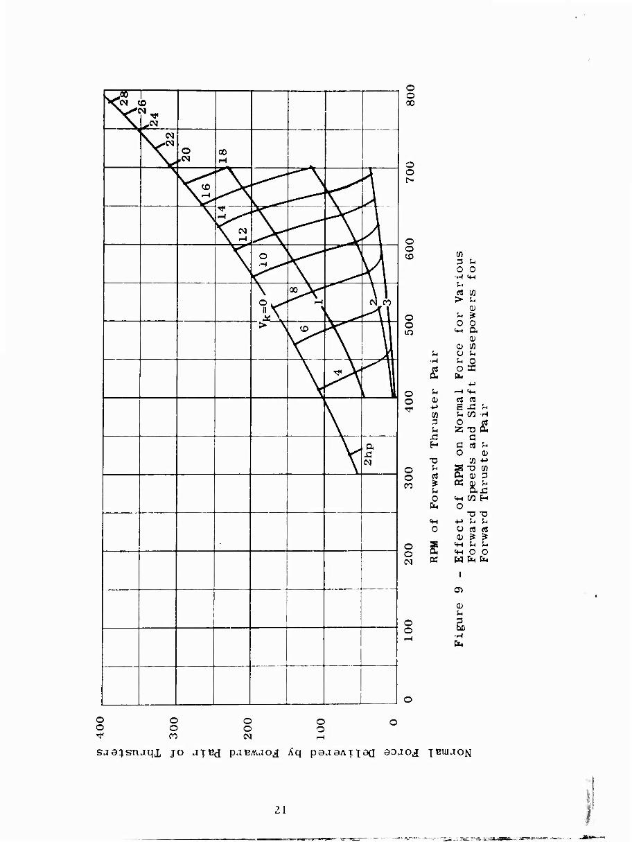
It should be emphasized that the large losses in normal force shown in Figure 8 apply to the case where all available thruster power is utilized. The loss for the case of constant rpm is somewhat greater as will be shown in the following paragraph.
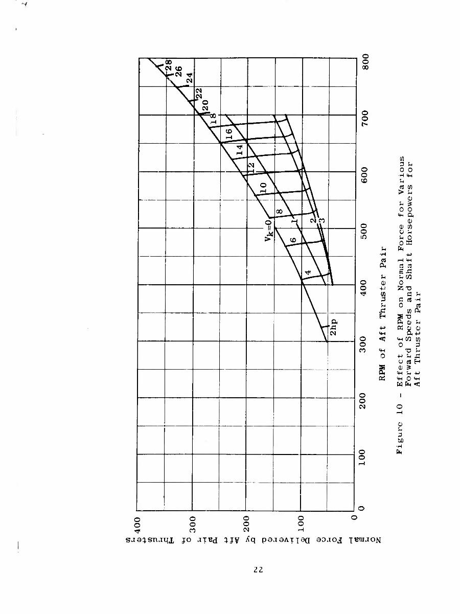
The effect of thruster rpm on normal force for each of several speeds is shown for the forward and aft pairs in Figures 9 and 10, respectively. Superimposed on these figures are contours of maximum rpm for equal shp. It may be noted from these contours that for any given shp the maximum rpm of a thruster pair increases with forward speed. This is due to the fact that the torque coefficient decreases with forward speed (see Figure 7). Alter- natively, for the same reason, for constant rpm, the shaft horsepower tends to decrease as the ahead speed increases.
The relative effects of forward speed on lateral forces are essentially the same as those for the normal forces. The magnitude of the lateral force in any given case can be obtained by multiplying the appropriate normal force in Figures 8, 9, and 10 by N/3
-.
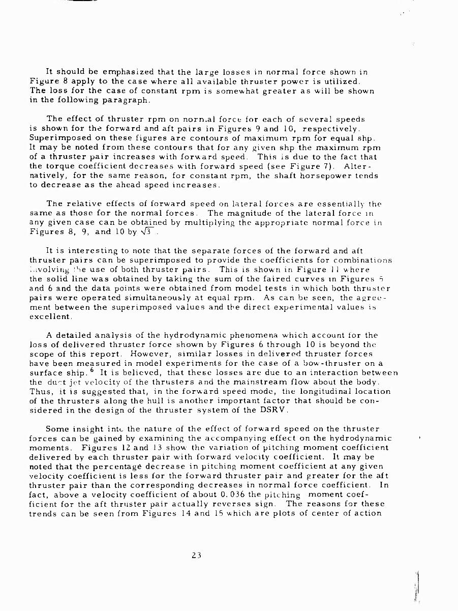
It is interesting to note that the separate forces of the forward and aft thruster pairs can be superimposed to provide the coefficients for combinations involving the use of both thruster pairs. This is shown in Figure i 1 where the solid line was obtained by taking the sum of the faired curves in Figures 5 and 6 and the data points were obtained from model tests in which both thruster pairs were operated simultaneously at equal rpm. As can be seen, the agree- ment between the superimposed values and the direct experimental values is excellent.
A detailed analysis of the hydrodynamic phenomena which account lor the loss of delivered thruster force shown by Figures 6 through 10 is beyond the scope of this report. However, similar losses in delivered thruster forces have been measured in model experiments for the case of a bow-thruster on a surface ship. It is believed, that these losses are due to an interaction between the du^t jet velocity of the thrusters and the mainstream flow about the body. Thus, it is suggested that, in the forward speed mode, the longitudinal location of the thrusters along the hull is another important factor that should be con- sidered in the design of the thruster system of the DSRV.
Some insight intc the nature of the effect of forward speed on the thruster forces can be gained by examining the accompanying effect on the hydrodynamic moments. Figures 12 and 13 show the variation of pitching moment coefficient delivered by each thruster pair with forv/ard velocity coefficient. It may be noted that the percentage decrease in pitching moment coefficient at any given velocity coefficient is less for the forward thruster pair and greater for the aft thruster pair than the corresponding decreases in normal force coefficient. In fact, above a velocity coefficient of about 0. 036 the pitching moment coef- ficient for the aft thruster pair actually reverses sign. The reasons for these trends can be seen from Figures 14 and 15 which are plots of center of action
23
i
.
1
1
OC
1
l
1
/
>
/
/
■♦-1
+ /
fw
d
i 1
X o
o
o
Cfl E u -o u 0 G 0 z cj x:
o <£>
■t-i
a -u a) o ^ M
pj 0 ^ S H G U
b o o tx •H b- C U -i
■t-i ■H Q) *-> a HH J3 «1 O 0) t« -M « lO ■H dl m
o -« a •H u o o m SfH 4H >> If) <D +J +J 'M 0 ■H G -H u cj ai «
CJ >» r-H CJ t ■M GJ -H u
•H > ^ 0) CJ ^-1 -M 0 SH 0 (fl ^ 0 0 3
^ ■M r
o (D U '4-1 « 4-1
I'J <*H 0 'H W fe <
o a-
o o
I o
Z4
CD
( )
CO )
I
( fD
c 1
L i I \
)
\ i
'"*\
c
\
, \
1
n o X o
o 00
o
o
O
o
a 0)
<♦-( 0) o Ü
>. •M •H o o
o CO
o
I
„H ^naTOjjjaoo ^aaiooji SuiqoiTd
i
X
I O
C fi •H
J3 fcl
Ü o ■M ■M ■H tn 0, 3
t. ö si 0 H
■M •D c U
a; rt •H * Ü u
•H o <tH b KH
0) Ur
0 0 u t-l
>. ■M
■(-> c •H a; CJ •H
0 u rH •H
0) tH
> <« OJ
m 0 0 u
■(-> -t->
u c 0) o
SH s 4-1 0 w s
(N
0)
25
•'
1 X o
o
o
o to
o
tx c
■H
G 0
ß
o
si H
o Ü -M •H ^-1 o ■H SH < u ^M
■H 0) t, <H 0 0 f-l (J 1H 0) 0 >.-M u ■M C
o >. 't •M o u
■H ,--( -H CJ a) "H 0 >*H
-H 0) Ä i<H 0 > o u
o u c CO m m
tH 0 W S
I
0)
■H
IN
n i o
I 1
„W ^UOTOTJJOOO ^uomow SajimTd
26
I V
\ >
\
1
\
\
\ ^
\ \ k \ —
o QO
o
o CD
r-i
C c
■H
'X
s •D c -o 0 JH
o Z rj m JJ C 0 D
4-> ■M C '« c o o o •H W •H u o u •H C
rf •H «♦H 0 4H l+H -H «H 1) -M OJ 0 0 0 u < u
>. -H >. ^ 0
+J -i O •H Ü u CO Ü 0 o
0 rH -M l-l o c £ > (D >
t o
f te
r C
o CJ (/) (N
- E
ffe
T
hru
o
CO (N
jXx ^uaT3TJJ9oD Ja^snam jo nox^av J0 Ja^aao
27
I i -,— —, ■■ ■ _ -■ - - ■„■—- ■
n i o H X o 00
o
C« o a (£>
ndimensio
ir
O 10 Sä
•* a 4J b O «H
•M •M a a u <D 0) 0 •H •H m
o Ü c Tf •H •H G
«H «H 0 «H «H -H O Q) +J
0 0 Ü u U-J;
>» >»=H ■M ■M 0
o •H •H CO y Ü f".
0 0 O (H rH +J 0 a» a >
of V
er Ce
o •M 4J (N
5 - Effec
Thrus
o PH
rH 0 u
be •H
ja^snjqx jo noT^oy jo aa^uao
28
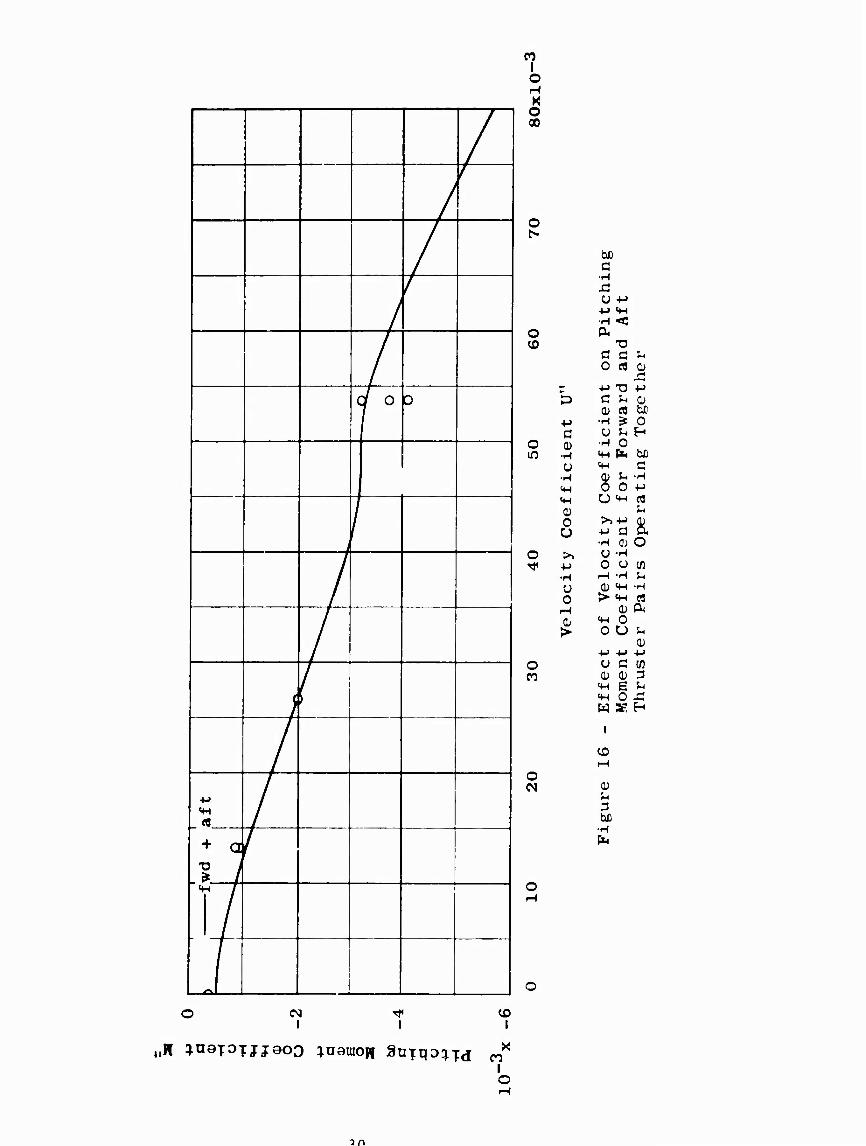
of normal force coefficient versus velocity coefficient. The nondirnensional center of action x ' is defined as -M1,/Z,,and is expressed in body lengths with respect to the center of gravity. For the forward thraster pair, the center of action moves forward from the centerline of the thruster pair until it reaches a point about 3. 2 body lengths ahead of the center of gravity. In this case, the movement is beneficial from the standpoint of control since the lever arm with respect to the reference point is always increasing. Thus, for a range of speeds up to 3 knots, although the normal force decreases by about 90 percent, the pitching moment only decreaser 40 percent.
For the aft thruster pair, the center of action also moves forward with increasing velocity coefficient but not at as great a rate as for the forward pair. However, it moves from a point aft of the center of gravity to a point on the center of gravity at a velocity coefficient of 0. 036 and, then, at higher velocity coefficients it actually moves forward of the center of gravity. This illustrates the cause of the change in sense of the pitching moment which was mentioned previously.
As for the normal forces, the pitching moments developed by the separate thr . cter pairs can also be superimposed. This is shown by P'igure 16. Again, in spi.te of the completely different character of the center of action curves for the forward and aft thruster pairs, the agreement between the superimposed and experimental values is excellent. This indicates, that for all practical purposes, there s no interaction between the forward and aft thruster pairs.
The effeci .orward speed on the center of action of lateral forces is the same as tho e tor the center of action of the normal forces. Consequently, the yawing moment coefficients produced by the thrusters can be determined by multiplying the appropriate pitching moment coefficients in Tigures JZ and 1 3 by \[J~.
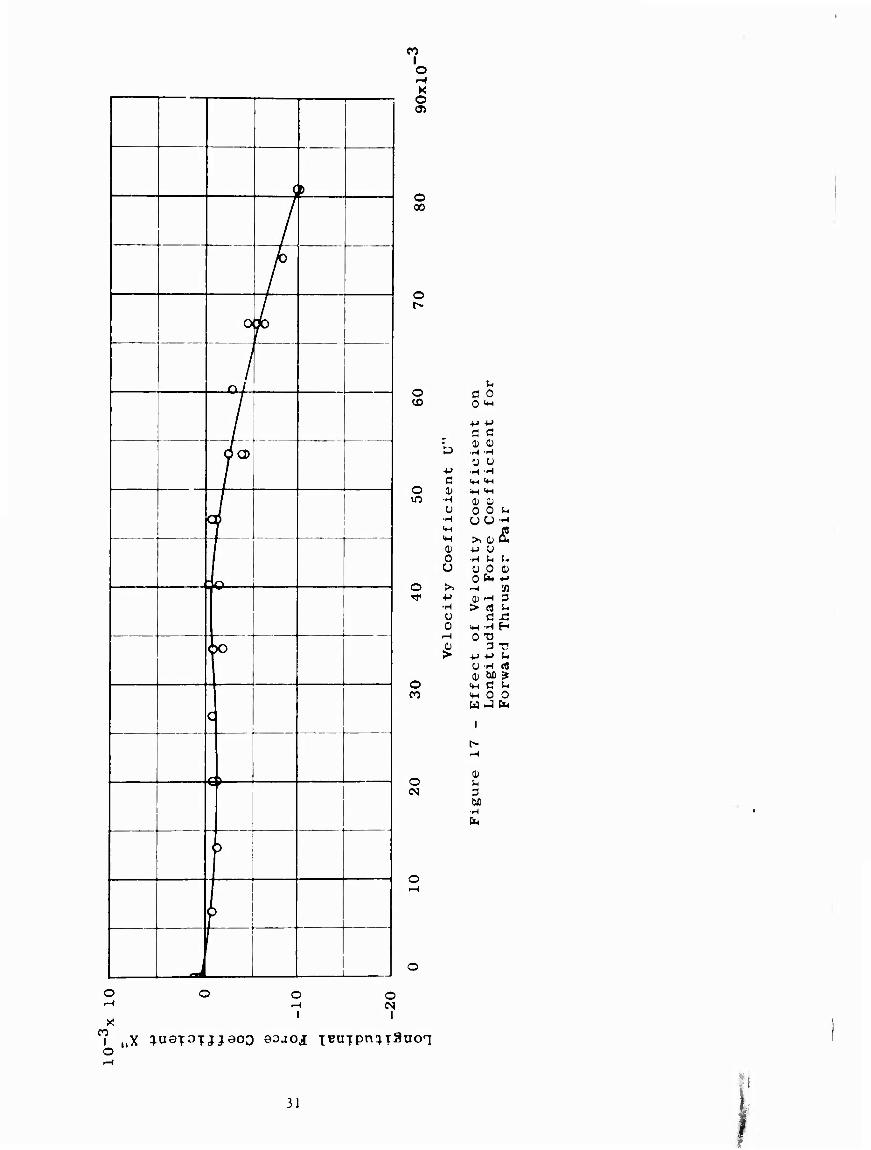
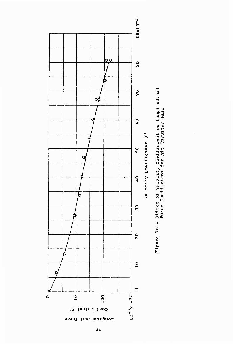
In addition to the effects on normal and lateral forces and pitching and yawing moments produced by the thrusters, there is an attendant increase in longitudinal (resistance) force with forward speed. This is shown in Figures 17 and 18. It can be seen from Figure 17 that, when the forward thruster pair is used, the longitudinal force coefficient does not change significantly until a velocity coefficient of about 0. 040. However, above this point there is a com- paratively sharp increase. On the other hand, when the aft thruster pair ic used, there is a large increase in longitudinal force coefficient with forward speed starting immediately at a velocity coefficient of zero. This is consistent with the fact that the flow about the afterbody of submerged forms is much more critical insofar as resistance is concerned than the flow about the fore- body. Although the change in longitudinal force caused by the forward pair is much different than that produced by the aft pair, the separate effects can be superimposed as shown byFigure 19.
29
» WC^K.WWi'T- "
/
/
/
/
/
/
/ c r D
/
;
/
/
+ a * 1
/
<♦
7 i
CO I o H K O 00
o f^
itching
Aft
o A CO 73
a a ^ 0 c« o
z -M TJ -M D fi ^ (1)
■M •H ^ 0 a O ^ H
o 0) •H 0 m •H m fa be
Ü «H Ö •H 0) S-> -H 4-1 0 0 -M HH O ^ rt 0) SH
0 u ■M a a •H o; O
o >> O -H f 4-> o o tfl
•H r-l -H ^ o (U «H -H o > «H £« iH (1) Cl( 0 «H 0 > 0 u ^
-M -M -M o O C [fl n
Effe
Mome
Thru
o (N
O i-l
(N I I
CD I
CD
(D U
biD
i
CO
If D
/
/
o /
/ 0/
/ oa>
i i !
1
JQ
j
1°
q
/-*!.
O
I J
K O Oi
o 00
o
o CD
O 10
O
y
■*->
c •H u
•H (H MH
0) 0 u
u 0
o
o eg
o rH
I
o
u a 0 0 'H
■M ■<-'
C Ö 0) OJ
•H -H u u •H -H <*-( <« tH IM 0) 0) 0 0 uu >> 0) •M U •H U u 0 0 t*
> « HH -H H 0 "O
U -H efl 0) be j«
<»H C S-c m O O W J EK
I
0)
M •H
o
31
o
CO I o l-l X o
O 00
o rt f*
ongit
udin
P
air
o J ^0
a a) 0 V
z •M 3 a a j-
a> x3 ■p ■H H 0 Ü
o 0) •H •(-> m •H «H «M
U «H < ■H 0) «H 0 5-. <H O 0 <D «H 0 >. Ü •H a
o >> Ü 0) •f +J 0 -H
•H ^ Ü O 0) -H 0 > «M
1-^ <H OJ «H a> > 0 0
o O QJ n
Eff
e F
ore
o (N
O rH
I
o
QOJ.01 TBUTpn^jaaoq
32
o en
i
x i o
00
0/ u p be
•H
/
/
/
/
f
/
/
i
/
/ 1 +J
/ + ' J f .
1 AJ
/
K O 00
o
o
o
o
■M c (D
•H O
•H «H «H 0) o u
•M •H Ü 0
o
o
X n i o
o r-l
I
o I
O n i
^H u rt 0) a ■M •H M TJ D 3 u
•t-> xi HH be a 4J O "M ►J<:
flT3 O c
es ■M a T3 Q i-
•H CJ u ^
•H ^ SH 0 ^ «M b 0) 0) £ 0 u 4J u 0 0)
<+H be >> 0 +J V EH •H c o 0) bC o •H C3 r-l Ü •H o •H •M > <w aj
«M S-
0 0 21 uo
•(-> u (1) 01 0) Ü u
«n }-. H «fH 0 03 H (>4 CX
1
cn ^
0) S-. 3 be
•H fc
WX ^naT^TJJ^oO ^-oj iBUTpn^TSuoq
3 3
■^—Tr~^5-i^
In summary, there is substantial decrease in normal force, lateral force, pitching moment, and yawing moment and a substantial increase in longitudinal force with forward speed for any given thruster rpm or thruster power. This is believed to be due to an interaction between the thruster jet velocity and the mainstream flow about the body. The interaction apparently cause« large changes in pressure distribution about the body as evidenced by the large move - ment in center of action of the thruster forces with forward speed. It is con- cluded, therefore, that the aft thruster pair, in particular, is ineffective as a control device when operating in the forward speed mode above a speed of one knot. The forward thruster pair may have some usefulness for operation in vertical-plane maneuvers below critical speed as will be discussed later in this report.
Broadside Mode
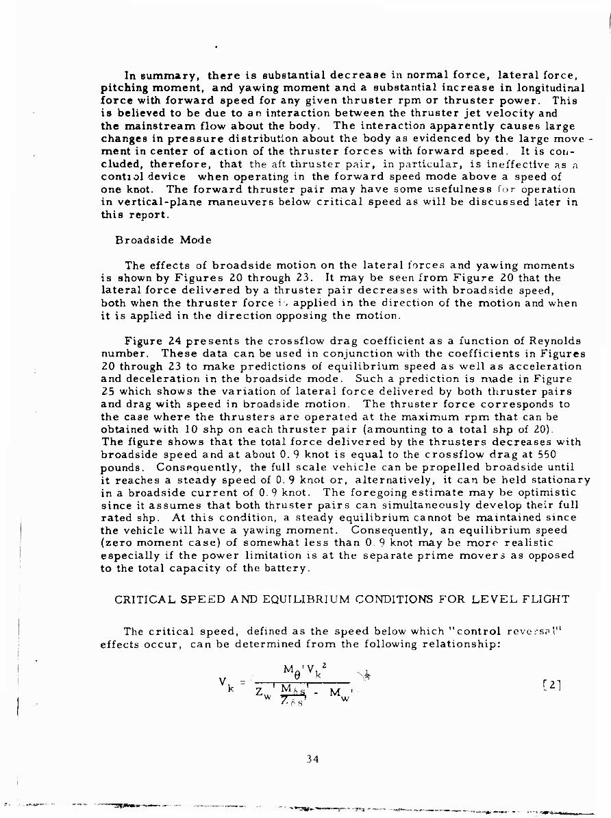
The effects of broadside motion on the lateral forces and yawing moments is shown by Figures 20 through 23. It may be seen from Figure 20 that the lateral force delivered by a thruster pair decreases with broadside speed, both when the thruster force i . applied in the direction of the motion and when it is applied in the direction opposing the motion.
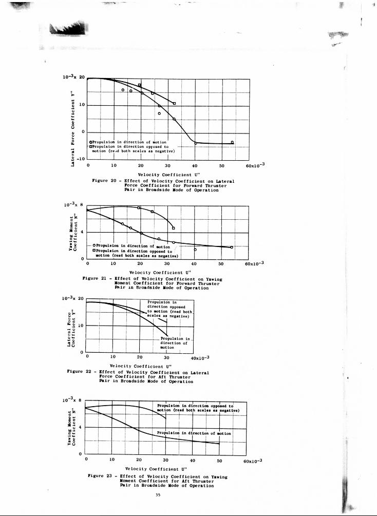
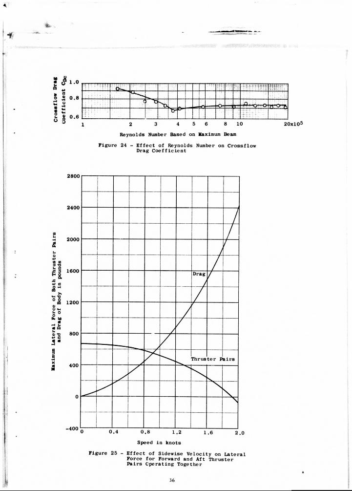
Figure 24 presents the crossflow drag coefficient as a function of Reynolds number. These data can be used in conjunction with the coefficients in Figures 20 through 23 to make predictions of equilibrium speed as well as acceleration and deceleration in the broadside mode. Such a prediction is made in Figure 25 which shows the variation of lateral force delivered by both thruster pairs and drag with speed in broadside motion. The thruster force corresponds to the case where the thrusters are operated at the maximum rpm that, can be obtained with 10 shp on each thruster pair (amounting to a total shp of 20). The figure shows that the total force delivered by the thrusters decreases with broadside speed and at about 0. 9 knot is equal to the crossflow drag at 550 pounds. Consequently, the full scale vehicle can be propelled broadside until it reaches a steady speed of 0.9 knot or, alternatively, it can be held stationary in a broadside current of 0.9 knot. The foregoing estimate may be optimistic since it assumes that both thruster pairs can simultaneously develop their full rated shp. At this condition, a steady equilibrium cannot be maintained since the vehicle will have a yawing moment. Consequently, an equilibrium speed (zero moment case) of somewhat less than 0.9 knot may be more realistic especially if the power limitation is at the separate prime movers as opposed to the total capacity of the battery.
CRITICAL SPEED AND EQUILIBRIUM COrTOITIONS FOR LEVEL FLIGHT
The critical speed, defined as the speed below which "control reversaV effects occur, can be determined from the following relationship:
v ^'V 'A
34
■■»•-■«fc--
OPropulslon In direction of notion •Propulsion In direction opposed to motion (read both scales as negative)
60x10"
Veloc i ty C o e f f i c i e n t U" Figure 20 - E f f e c t of Ve loc i ty C o e f f i c i e n t on L a t e r a l
Force C o e f f i c i e n t f o r Forward T h r u s t e r P a i r in Broadside Mode of Opera t ion
OPropulsion In d irec t ion of notion • Propulsion In d irect ion opposed to
not ion (read both sca les as negative)
60x10
Velocity Coefficient U" Figure 21 - Effect of Velocity Coefficient on Yawing
Moment Coefficient for Forward Thruster Pair in Broadside Mode of Operation
10"3x 20
o > 0 - +* £ c fc«j 10 — o (3
2%
Velocity Coefficient U" Figure 22 - Effect of Velocity Coefficient on Lateral
Force Coefficient for Aft Thruster Pair in Broadside Mode of Operation
8 Propulsion in direction opposed to notion (read both scales as negative) — J i I
4 .^Propuls ion In d i rec t ion of notion
0 0 10 20 30 40 50
Veloc i ty C o e f f i c i e n t U" Figure 23 - E f f e c t of Ve loc i ty C o e f f i c i e n t on Yawing
Moment C o e f f i c i e n t f o r Aft T h r u s t e r Pa i r in Broadside Mode of Opera t ion
Propulsion In d irect ion opposed to notion (read b< oth scales as negative)
Propulsion In . direction of motion
40xl0-3
M £ !" r?1.0
O ® 0.8 £ « 3 13 o * 5 I °-6
-! ! 1 : TTTT: : :: " ' ! cw • j J t r j ; : t-~]-T-4 T3 T t t
( > "t > > 1 ,n , IQ—o rro-js
2 3 4 5 6 8 10
Reynolds Number Based on Maximum Beam
Figure 24 - Effect of Reynolds Number on Crossflow Drag Coefficient
20xl05
(0 u •H
& u 0)
(0 (0 3 TJ S* C 5 3
£3 •M C
>» «M -O
0) y <M
o 0 b. M a —t k. « Q b J) T3 « a 4 a
2800
2400
2000
1600
1200
800
400
-400
/
/
/ /
/ Drag
J /
i /
A f
/
1 —
y Thrus t e r P a i r s
I
1 1
0.4 0.8 1.2
Speed in knots
1.6 2 .0
Figure 25 - Effect of Sidewise Velocity on Lateral Force for Forward and Aft Thruster Pairs Operating Together
36
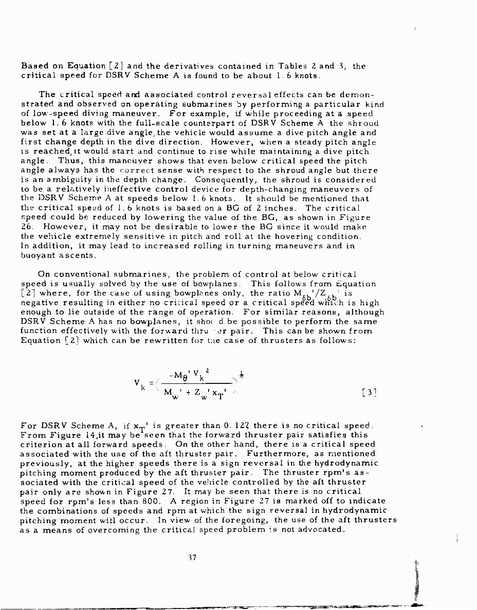
Based on Equation [2] and the derivatives contained in Tables 2 and 3, the critical speed for DSRV Scheme A is found to be about 1. 6 knots.
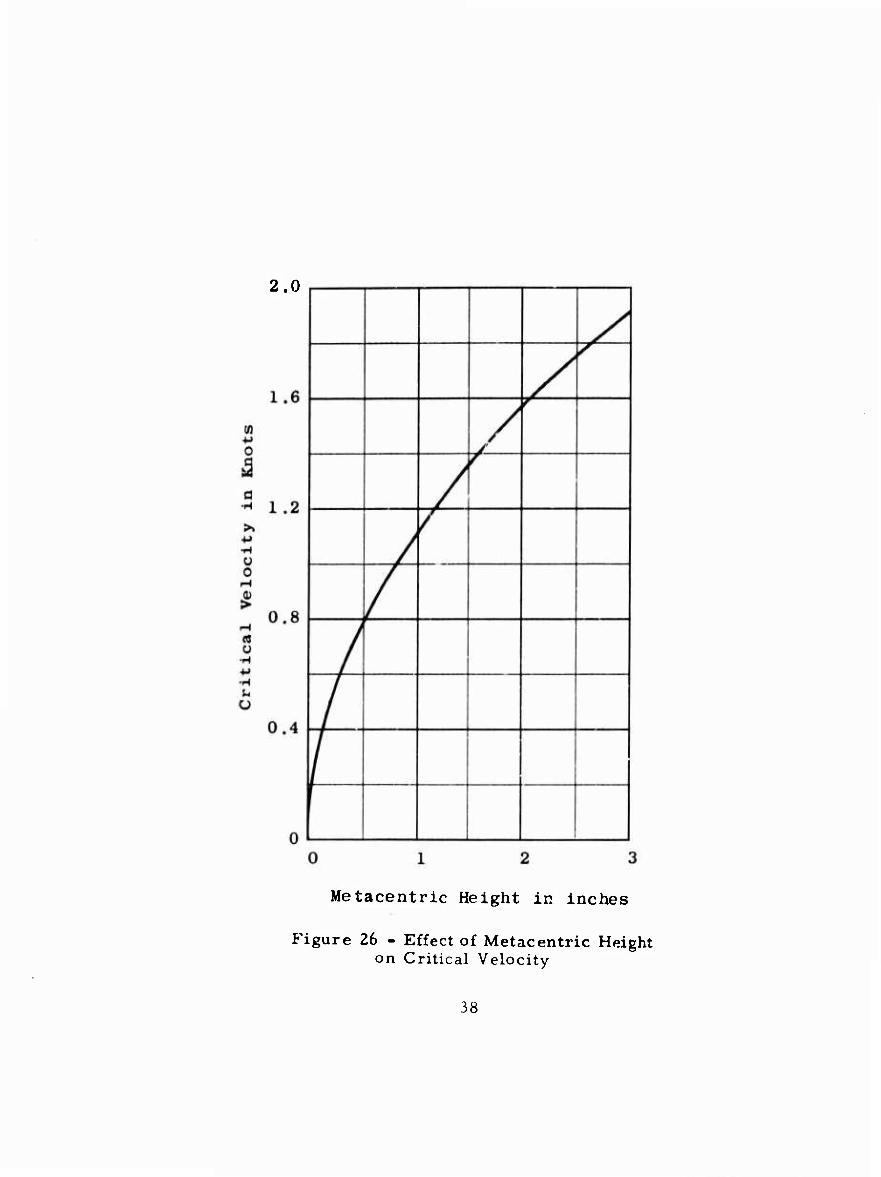
The critical speed and associated control reversal effects can be demon- strated and observed on operating submarines by performing a particular kind of lov.-speed diving maneuver. For example, if while proceeding at a speed below 1. 6 knots with the full-scale counterpart of DSRV Scheme A the shroud was set at a large dive angle,the vehicle would assume a dive pitch angle and first change depth in the dive direction. However, when a steady pitch angle is reachedjit would start and continue to rise while maintaining a dive pitch angle. Thus, this maneuver shows that even below critical speed the pitch angle always has the correct sense with respect to the shroud angle but there is an ambiguity in the depth change. Consequently, the shroud is considered to be a relatively ineffective control device for depth-changing maneuvers of the DSRV Scheme A at speeds below 1. 6 knots. It should be mentioned that the critical speed of 1. 6 knots is based on a BG of 2 inches. The critical speed could be reduced by lowering the value of the BG, as shown in Figure 26. However, it may not be desirable to lower the BG since it would make the vehicle extremely sensitive in pitch and roll at the hovering condition. In addition, it may lead to increased rolling in turning maneuvers and in buoyant ascents.
On conventional submarines, the problem of control at below critical speed is usually solved by the use of bowplanes. This follows from Equation [2] where, for the case of using bowplanes only, the ratio M. '/Z , ; is negative resulting in either no critical speed or a critical speed which is high enough to lie outside of the range of operation. For similar reasons, although DSRV Scheme A has no bowplanes, it shoi d be possible to perform the same function effectively with the forward thru ^T pair. This can be shown from Equation [2] which can be rewritten for lae case of thrusters as follows:
V, =f 2 iL. k ax • + Z - x .
w w I M ' +ZJ*T, " [3]
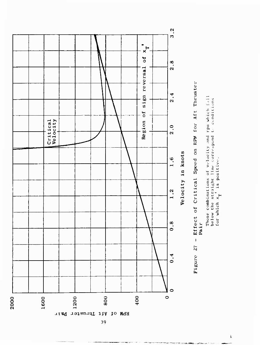
For DSRV Scheme A, if x* is greater than 0. 12"? there is no critical speed. From Figure 14,it may be seen that the forward thruster pair satisfies this criterion at all forward speeds. On the other hand, there is a critical speed associated with the use of the aft thruster pair. Furthermore, as mentioned previously, at the higher speeds there is a sign reversal in the hydrodynamic pitching moment produced by the aft thruster pair. The thruster rpm's as- sociated with the critical speed of the vehicle controlled by the aft thruster pair only are shown in Figure 27. It may be seen that there is no critical speed for rpm's less than 800. A region in Figure 27 is marked off to indicate the combinations of speeds and rpm at which the sign reversal in hydrodynamic pitching moment will occur. In view of the foregoing, the use of the aft thrusters as a means of overcoming the critical speed problem is not advocated.
37
2.0
Metacentric Height in inches
Figure 26 - Effect of Metacentric Height on Critical Velocity
38
\ 1 * H
\ ■
0
1 , 1 ^
et m u 1)
\
>
a
\
DO
M
ical
cit
y J \
0
c 0
SCri
t V
elo [/
\
\
\ y
\
1
\
\
\
y
\
\
\
CO
00
(N
(N
O
CD
(N
00
o
o
0 *■>
75 3 , '« — X r - c H fj u ■•-,
M ■-( -a <
3 3 . u
C E a. .
Vn u u
5: tj tj
s C C
Cd >, n
c ±J 'J
tfl 0 •M u ■M u u O c X3
o 0 0;
> X a > ii —<
a •H
CO U-l -H -^ O -< i0
0 ^H '^ u a. >> P5 c X
■*-> o o M m •H •H
•-J -H -H
Ü 0
■M 4-1 (fl
•H C iJ f- I-I •^ ifl X
^ o ^3 B a- x o J: u
tH U W •'H 0
(L S 3 ■t-> in 0
CJ 0 -H V4 £ a; O
(D Si H J3 ^ 4-( -H ** e« W 04
r^ fNJ
o u 3 hC
o o o
o o
o o
O o oo
o o
aiBd JQ^snam, ^JV JO WdH
39
Ui
Due to asymmetries, a submarine usually has to carry a steady pitch angle and steady control-surface angle to maintain a condition of horizontal equilibrium flight. The various combinations which will give equilibrium level flight can be estimated for DSRV Scheme A from the static stability and control derivatives listed in Tables 2 and 3.
The equilibrium pitch angles and shroud angles required for level flight of DSRV Scheme A when controlled with shroud only are shown as functions of speed in Figure 28» At speeds greater than 2 knots or less than I. 5 knots, the equilibrium pitch angle is less than | 11 degree and the equilibrium shroud angle is less than |2| degrees. However, between 1.5 and 2.0 knots, the equilibrium angles are large and include a case (critical speed) where no combination of finite shroud angle and pitch angle will produce a condition of steady level flight.
CONCLUSIONS
Hydrodynamic coefficients, derived from tests of a one-third scale model, are presented for use in detailed simulation studies of the motions of a specific design for the Deep Submergence Rescue Vessel (DSRV Scheme A ). Based on an analysis of these data, the following conclusions are made concerning the stability and control characteristics of DSRV Scheme A :
1. The submarine will have near-optimum dynamic stability in the vertical plane of motion (damping ratio between 0. 7 and 1.0) at all operating speeds greater than 1. 4 knots.
2. The submarine will be dynamically stable in the horizontal plane of motion and, therefore, should have good coursekeeping qualities.
3. Using the all movable shroud only, the submarine will have good control effectiveness in the vertical plane at forward speeds above critical speed and in the horizontal planes at all forward speeds, as evidenced by its ability to initiate a dive or change heading rapidly.
4. In general, the thrusters will be relatively ineffective as control dc'ices for operating in the forward speed mode; the normal force, lateral force, pitching moment, and yawing moment produced by the thrusters will decrease substantially and the longitudinal force will increase substantially with forward speed for any given thruster rpm or thruster power. The poor performance of the thrusters is believed to be due to an interaction between the thruster jet velocity and mainstream flow about the body which causes large changes in pressure distribution about the body as evidenced by the large movement in center of action of the thruster force with forward speed.
5. It should be possible to propel the submarine broadside until it reaches a steady speed of about 0. 9 knot or, alternatively, until it is held stationary in a broadside current of about 0. 9 knot.
40
/ \
y U / NJ
in
^> s
CD
m
CO
N
N I
+■» o a
•M •H o o a) >
saaaSap uj SQ QiSuy pnoaijs puc e 8T3UV ip:*Td
0) >
XI
cr
n a)
d o h
w
S V
i-H 00
Ü
ft I
00
oo
41
6. The critical speed of the submarine for control with shroud only will occur at about 1. 6 knots. The forward thruster pair can be used in lieu of the bowplanes found on conventional submarines to provide good control at forward speeds at or below 1. 6 knots; the aft thruster pair is not recommended for this purpose because of the sign reversal in the hydrodynamic pitching moment that will occur within the range of usable speeds.
ACKNOWLEDGMENTS
The author is grateful to Messrs. E. Dittrich, T. Mahoney, A. Magnuson, N. King, and B. Carson for their assistance in the experimental work; and to Messrs. M. Gertler and G. Hagen of the Stability and Control Division for their contributions and guidance. In addition, the helpful suggestions and participation in the test program of Messrs. J. Beveridge, F. Puryear, and G. Ober of the Propeller Branch are greatly appreciated.
42
APPENDIX A
LONGITUDINAL STABILITY AND CONTROL COEFFICIENTS
(Figures 29 - 37)
43