Embed Size (px)
Citation preview

4.1 Introduction
There are many reasons for studying initial and final conditions. The most important reason is thatthe initial and final conditions evaluate the arbitrary constants that appear in the general solutionof a differential equation.
In this chapter, we concentrate on finding the change in selected variables in a circuit whena switch is thrown open from closed position or vice versa. The time of throwing the switch isconsidered to be � = 0, and we want to determine the value of the variable at � = 0� and at� = 0+, immediately before and after throwing the switch. Thus a switched circuit is an electricalcircuit with one or more switches that open or close at time � = 0. We are very much interestedin the change in currents and voltages of energy storing elements after the switch is thrown sincethese variables along with the sources will dictate the circuit behaviour for � � 0.
Initial conditions in a network depend on the past history of the circuit (before � = 0�) andstructure of the network at � = 0+, (after switching). Past history will show up in the form ofcapacitor voltages and inductor currents. The computation of all voltages and currents and theirderivatives at � = 0+ is the main aim of this chapter.
4.2 Initial and final conditions in elements
4.2.1 The inductor
The switch is closed at � = 0. Hence � = 0� correspondsto the instant when the switch is just open and � = 0+
corresponds to the instant when the switch is just closed.The expression for current through the
inductor is given by
� =1
�
����
���Figure 4.1 Circuit for explaining
switching action of an inductor
www.allsyllabus.com
vtu.allsyllabus.com
www.allsyllabus.com

278 � Network Theory
� � =1
�
0����
��� +1
�
��0�
���
� �(�) = �(0�) +1
�
��0�
���
Putting � = 0+ on both sides, we get
�(0+) = �(0�) +1
�
0+�0�
���
� �(0+) = �(0�)
The above equation means that the current in an inductor cannot change instantaneously.Consequently, if �(0�) = 0, we get �(0+) = 0. This means that at � = 0+, inductor will actas an open circuit, irrespective of the voltage across the terminals. If �(0�) = ��, then �(0+) = ��.In this case at � = 0+, the inductor can be thought of as a current source of �� A. The equivalentcircuits of an inductor at � = 0+ is shown in Fig. 4.2.
������
Figure 4.2 The initial-condition equivalent circuits of an inductor
The final-condition equivalent circuit of an inductor is derived from the basic relationship
� = ���
��
Under steady condition,��
��= 0. This means, � = 0 and hence � acts as short at � =� (final
or steady state). The final-condition equivalent circuits of an inductor is shown in Fig.4.3.
�����
��
��
Figure 4.3 The final-condition equivalent circuit of an inductor
www.allsyllabus.com
vtu.allsyllabus.com
www.allsyllabus.com

Initial Conditions in Network � 279
4.2.2 The capacitor
The switch is closed at � = 0. Hence, � = 0�
corresponds to the instant when the switch isjust open and � = 0+ corresponds to the instantwhen the switch is just closed. The expressionfor voltage across the capacitor is given by
� =1
����
��� Figure 4.4 Circuit for explaining
switching action of a Capacitor
� �(�) =1
0����
��� +1
��0�
���
� �(�) = �(0�) +1
��0�
���
Evaluating the expression at � = 0+, we get
�(0+) = �(0�) +1
0+�0�
��� � �(0+) = �(0�)
Thus the voltage across a capacitor cannot change instantaneously.
If �(0�) = 0, then �(0+) = 0. This means that at � = 0+, capacitor acts as short circuit.Conversely, if �(0�) =
0
then �(0+) =0
. These conclusions are summarized in Fig. 4.5.
Figure 4.5 Initial-condition equivalent circuits of a capacitor
The final–condition equivalent network is derived from the basic relationship
� = ��
��
Under steady state condition,��
��= 0. This is, at � = �, � = 0. This means that � = �
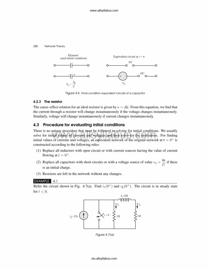
or in steady state, capacitor acts as an open circuit. The final condition equivalent circuits of acapacitor is shown in Fig. 4.6.
www.allsyllabus.com
vtu.allsyllabus.com
www.allsyllabus.com
280 � Network Theory
Figure 4.6 Final-condition equivalent circuits of a capacitor
4.2.3 The resistor
The cause–effect relation for an ideal resistor is given by � = ��. From this equation, we find thatthe current through a resistor will change instantaneously if the voltage changes instantaneously.Similarly, voltage will change instantaneously if current changes instantaneously.
4.3 Procedure for evaluating initial conditionsThere is no unique procedure that must be followed in solving for initial conditions. We usuallysolve for initial values of currents and voltages and then solve for the derivatives. For findinginitial values of currents and voltages, an equivalent network of the original network at � = 0+ isconstructed according to the following rules:
(1) Replace all inductors with open circuit or with current sources having the value of currentflowing at � = 0+.
(2) Replace all capacitors with short circuits or with a voltage source of value �� =0
if thereis an initial charge.
(3) Resistors are left in the network without any changes.
EXAMPLE 4.1Refer the circuit shown in Fig. 4.7(a). Find �1(0
+) and ��(0+). The circuit is in steady state
for � � 0.
� ����� �� ��
�
Figure 4.7(a)
www.allsyllabus.com
vtu.allsyllabus.com
www.allsyllabus.com

Initial Conditions in Network � 281
SOLUTION
The symbol for the switch impliesthat it is open at � = 0� and thenclosed at � = 0+. The circuit isin steady state with the switch open.This means that at � = 0�, induc-tor � is short. Fig.4.7(b) shows theoriginal circuit at � = 0�.Using the current division principle,
��(0�) =
2� 1
1 + 1= 1A
�
�� ��
�
Figure 4.7(b)
Since the current in an inductor cannot change instantaneously, we have
��(0+) = ��(0
�) = 1A
At � = 0�, �1(0�) = 2 � 1 = 1A. Please note that the current in a resistor can changeinstantaneously. Since at � = 0+, the switch is just closed, the voltage across �1 will be equal tozero because of the switch being short circuited and hence,
�1(0+) = 0A
Thus, the current in the resistor changes abruptly form 1A to 0A.
EXAMPLE 4.2Refer the circuit shown in Fig. 4.8. Find ��(0
+). Assume that the switch was in closed state fora long time.
Figure 4.8
SOLUTION
The symbol for the switch implies that it is closed at � = 0� and then opens at � = 0+. Since thecircuit is in steady state with the switch closed, the capacitor is represented as an open circuit at� = 0�. The equivalent circuit at � = 0� is as shown in Fig. 4.9.
www.allsyllabus.com
vtu.allsyllabus.com
www.allsyllabus.com
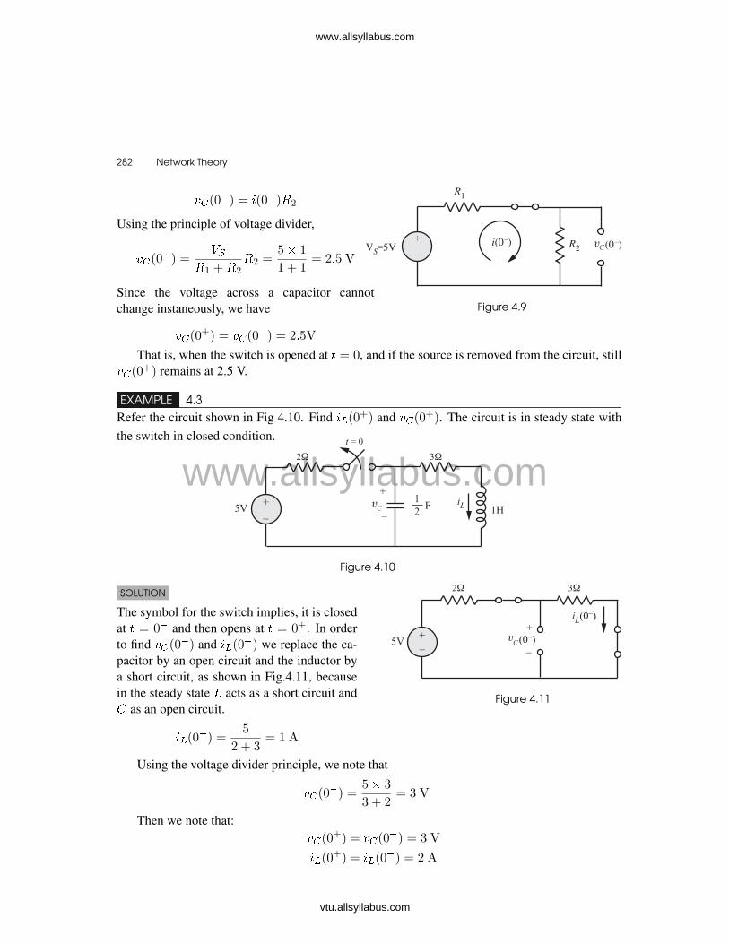
282 � Network Theory
��(0�) = �(0�)�2
Using the principle of voltage divider,
��(0�) =
��1 +�2
�2 =5� 1
1 + 1= 2�5 V
Since the voltage across a capacitor cannotchange instaneously, we have
��(0+) = ��(0
�) = 2�5V
Figure 4.9
That is, when the switch is opened at � = 0, and if the source is removed from the circuit, still��(0
+) remains at 2.5 V.
EXAMPLE 4.3Refer the circuit shown in Fig 4.10. Find ��(0
+) and ��(0+). The circuit is in steady state with
the switch in closed condition.
Figure 4.10
SOLUTION
The symbol for the switch implies, it is closedat � = 0� and then opens at � = 0+. In orderto find ��(0
�) and ��(0�) we replace the ca-
pacitor by an open circuit and the inductor bya short circuit, as shown in Fig.4.11, becausein the steady state � acts as a short circuit and as an open circuit.
��(0�) =
5
2 + 3= 1 A
Figure 4.11
Using the voltage divider principle, we note that
��(0�) =
5� 3
3 + 2= 3 V
Then we note that:��(0
+) = ��(0�) = 3 V
��(0+) = ��(0
�) = 2 A
www.allsyllabus.com
vtu.allsyllabus.com
www.allsyllabus.com
Initial Conditions in Network � 283
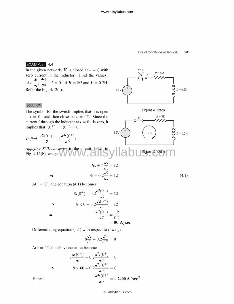
EXAMPLE 4.4In the given network, � is closed at � = 0 withzero current in the inductor. Find the values
of ����
��,�2�
��2at � = 0+ if � = 8٠and � = 0�2H.
Refer the Fig. 4.12(a).
SOLUTION
The symbol for the switch implies that it is openat � = 0� and then closes at � = 0+. Since thecurrent � through the inductor at � = 0� is zero, itimplies that �(0+) = �(0�) = 0.
To find��(0+)
��and
�2�(0+)
��2:
Applying KVL clockwise to the circuit shown inFig. 4.12(b), we get
Figure 4.12(a)
��
������
������
Figure 4.12(b)
��+ ���
��= 12
� 8�+ 0�2��
��= 12 (4.1)
At � = 0+, the equation (4.1) becomes
8�(0+) + 0�2��(0+)
��= 12
� 8� 0 + 0�2��(0+)
��= 12
���(0+)
��=
12
0�2= 60 A�sec
Differentiating equation (4.1) with respect to �, we get
8��
��+ 0�2
�2�
��2= 0
At � = 0+, the above equation becomes
8��(0+)
��+ 0�2
�2�(0+)
��2= 0
� 8� 60 + 0�2�2�(0+)
��2= 0
Hence�2�(0+)
��2= – 2400 A�sec2
www.allsyllabus.com
vtu.allsyllabus.com
www.allsyllabus.com

284 � Network Theory
EXAMPLE 4.5
In the network shown in Fig. 4.13, the switch is closed at � = 0. Determine ����
��,�2�
��2at � = 0+.
Figure 4.13
SOLUTION
The symbol for the switch implies that it is open at � = 0� and then closes at � = 0+. Since thereis no current through the inductor at � = 0�, it implies that �(0+) = �(0�) = 0.
������� ������
�������
Figure 4.14
Writing KVL clockwise for the circuit shown in Fig. 4.14, we get
��+ ���
��+
1
��0
�(� )�� = 10 (4.2)
� ��+ ���
��+ ��(�) = 10 (4.2a)
Putting � = 0+ in equation (4.2a), we get
���0+�+ �
���0+�
��+ ��
�0+�= 10
� �� 0 + ����0+�
��+ 0 = 10
����0+�
��=
10
�= 10 A/sec
Differentiating equation (4.2) with respect to �, we get
���
��+ �
�2�
��2+
�(�)
= 0
www.allsyllabus.com
vtu.allsyllabus.com
www.allsyllabus.com

Initial Conditions in Network � 285
At � = 0+, the above equation becomes
����0+�
��+ �
�2��0+�
��2+
��0+�
= 0
� �� 10 + ��2�
�0+�
��2+
0
= 0
� 100 +�2�
�0+�
��2= 0
Hence at � = 0+��2�
�0+�
��2= �100 A/sec2
EXAMPLE 4.6Refer the circuit shown in Fig. 4.15. The switch� is changed from position 1 to position 2 at� = 0. Steady-state condition having been
reached at position 1. Find the values of �,��
��,
and�2�
��2at � = 0+.
Figure 4.15SOLUTION
The symbol for switch � implies that it is in position 1 at � = 0� and in position 2 at � = 0+.Under steady-state condition, inductor acts as a short circuit. Hence at � = 0�, the circuit diagramis as shown in Fig. 4.16.
Figure 4.16
��0��=
20
10= 2A
Since the current through an inductor cannot changeinstantaneously, �
�0+�= � (0�) = 2A. Since there is
no initial charge on the capacitor, �� (0�) = 0. Sincethe voltage across a capacitor cannot change instanta-neously, ��
�0+�= �� (0�) = 0. Hence at � = 0+
the circuit diagram is as shown in Fig. 4.17(a).For � � 0+, the circuit diagram is as shown in Fig. 4.17(b).
Figure 4.17(a) Figure 4.17(b)
www.allsyllabus.com
vtu.allsyllabus.com
www.allsyllabus.com

286 � Network Theory
Applying KVL clockwise to the circuit shown in Fig. 4.17(b), we get
��(�) + ���(�)
��+
1
��0+
�(� )�� = 0 (4.3)
� ��(�) + ���(�)
��+ ��(�) = 0 (4.3a)
At � = 0+ equation (4.3a) becomes
���0+�+ �
���0+�
��+ ��
�0+�= 0
� �� 2 + ����0+�
��+ 0 = 0
� 20 +���0+�
��= 0
����0+�
��= �20 A/sec
Differentiating equation (4.3) with respect to �, we get
���
��+ �
�2�
��2+
�
= 0
At � = 0+, we get
����0+�
��+ �
�2��0+�
��2+
��0+�
= 0
� �� (�20) + ��2�
�0+�
��2+
2
= 0
Hence��2�
�0+�
��2� �2� 106 A�sec2
EXAMPLE 4.7In the network shown in Fig. 4.18, the switch is moved from position 1 to position 2 at � = 0. The
steady-state has been reached before switching. Calculate �,��
��, and
�2�
��2at � = 0+.
Figure 4.18
www.allsyllabus.com
vtu.allsyllabus.com
www.allsyllabus.com

Initial Conditions in Network � 287
Figure 4.18(a)
SOLUTION
The symbol for switch � implies that it is in posi-tion 1 at � = 0� and in position 2 at � = 0+. Understeady-state condition, a capacitor acts as an open cir-cuit. Hence at � = 0�, the circuit diagram is as shownin Fig. 4.18(a).
We know that the voltage across a capacitorcannot change instantaneously. This means that��
�0+�= �� (0�) = 40 V.
At � = 0�, inductor is not energized. This means that � (0�) = 0. Since current in an inductorcannot change instantaneously, �
�0+�= � (0�) = 0. Hence, the circuit diagram at � = 0+ is as
shown in Fig. 4.18(b).The circuit diagram for � � 0+ is as shown in Fig.4.18(c).
Figure 4.18(b) Figure 4.18(c)
Applying KVL clockwise, we get
��+ ���
��+
1
��0+
�(� )�� = 0 (4.4)
� ��+ ���
��+ ��(�) = 0
At � = 0+, we get
��(0+) + ���(0+)
��+ ��(0
+) = 0
� 20� 0 + 1��(0+)
��+ 40 = 0
���(0+)
��= �40A/ sec
Diferentiating equation (4.4) with respect to �, we get
���
��+ �
�2�
��2+
�
= 0
www.allsyllabus.com
vtu.allsyllabus.com
www.allsyllabus.com

288 � Network Theory
Putting � = 0+ in the above equation, we get
���(0+)
��+ �
�2�(0+)
��2+
�(0+)
= 0
� �� (�40) + ��2�(0+)
��2+
0
= 0
Hence�2�(0+)
��2= 800A/ sec2
EXAMPLE 4.8In the network shown in Fig. 4.19, �1(�) = ��� for � � 0 and is zero for all � � 0. If the capacitor
is initially uncharged, determine the value of�2�2��2
and�3�2��3
at � = 0+.
Figure 4.19
SOLUTION
Since the capacitor is initially uncharged,�2(0
+) = 0Referring to Fig. 4.19(a) and applying KCLat node �2(�):
�2(�)� �1(�)
�1+
��2(�)
��+
�2(�)
�2= 0
�
�1
�1+
1
�2
��2(�) +
��2(�)
��=
�1(�)
�1 Figure 4.19(a)
� 0�15�2 + 0�05��2��
= 0�1��� (4.5)
Putting � = 0+, we get
0�15�2(0+) + 0�05
��2(0+)
��= 0�1
� 0�15� 0 + 0�05��2(0
+)
��= 0�1
���2(0
+)
��=
0�1
0�05= 2 Volts� sec
www.allsyllabus.com
vtu.allsyllabus.com
www.allsyllabus.com
Initial Conditions in Network � 289
Differentiating equation (4.5) with respect to �, we get
0�15��2��
+ 0�05�2�2��2
= �0�1��� (4.6)
Putting � = 0+ in equation (4.6), we find that
�2�2(0+)
��2=�0�1� 0�3
0�05= �8 Volts/ sec2
Again differentiating equation (4.6) with respect to �, we get
0�15�2�2��2
+ 0�05�3�2��3
= 0�1��� (4.7)
Putting � = 0+ in equation (4.7) and solving for�3�2��3
(0+), we find that
�3�2(0+)
��3=
0�1 + 1�2
0�05= 26 Volts/ sec3
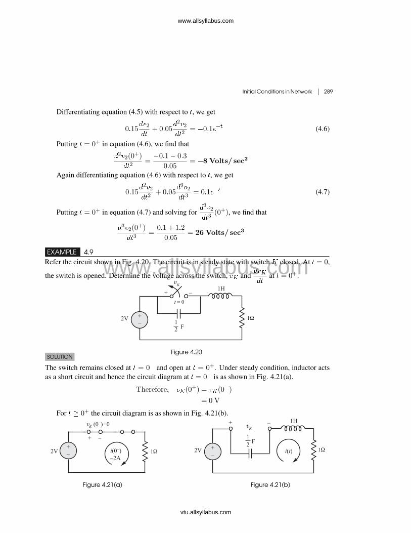
EXAMPLE 4.9Refer the circuit shown in Fig. 4.20. The circuit is in steady state with switch � closed. At � = 0,
the switch is opened. Determine the voltage across the switch, �� and�����
at � = 0+.
Figure 4.20SOLUTION
The switch remains closed at � = 0� and open at � = 0+. Under steady condition, inductor actsas a short circuit and hence the circuit diagram at � = 0� is as shown in Fig. 4.21(a).
Therefore� ��(0+) = ��(0�)
= 0 V
For � � 0+ the circuit diagram is as shown in Fig. 4.21(b).
Figure 4.21(a) Figure 4.21(b)
www.allsyllabus.com
vtu.allsyllabus.com
www.allsyllabus.com
290 � Network Theory
�(�) = �����
At (�) = 0+, we get
�(0+) = ���(0+)
��
Since the current through an inductor cannot change instantaneously, we get
�(0+) = �(0�) = 2A
Hence� 2 = ���(0+)
�����(0+)
��=
2
=
212
= 4V/ sec
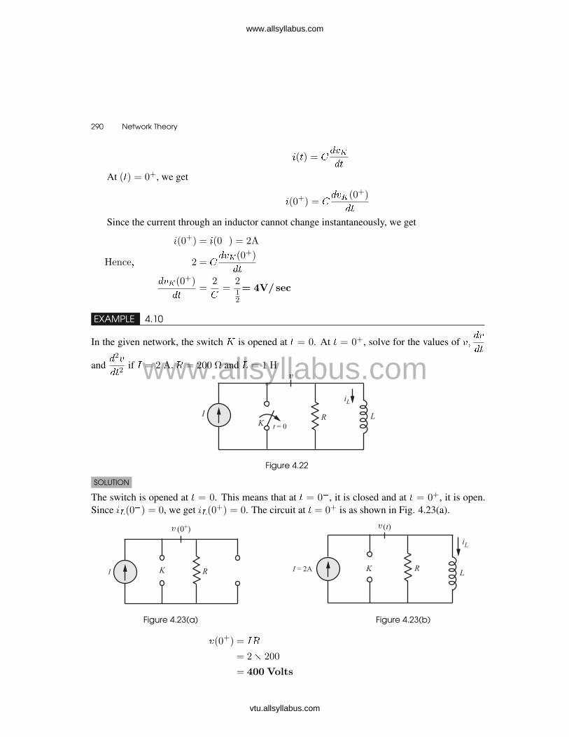
EXAMPLE 4.10
In the given network, the switch � is opened at � = 0. At � = 0+, solve for the values of ����
��
and�2�
��2if � = 2 A� � = 200 ٠and � = 1 H
Figure 4.22
SOLUTION
The switch is opened at � = 0. This means that at � = 0�, it is closed and at � = 0+, it is open.Since ��(0�) = 0, we get ��(0+) = 0. The circuit at � = 0+ is as shown in Fig. 4.23(a).
Figure 4.23(a) Figure 4.23(b)
�(0+) = ��
= 2� 200
= 400 Volts
www.allsyllabus.com
vtu.allsyllabus.com
www.allsyllabus.com
Initial Conditions in Network � 291
Refer to the circuit shown in Fig. 4.23(b).For � � 0+, the KCL at node �(�) gives
� =�(�)
�+
1
�
��0+
�(� )�� (4.8)
Differentiating both sides of equation (4.8) with respect to �, we get
0 =1
�
��(�)
��+
1
��(�) (4.8a)
At � = 0+, we get1
�
��(0+)
��+
1
��(0+) = 0
�1
200
��(0+)
��+
1
1� 400 = 0
���(0+)
��= �8� 104 V/ sec
Again differentiating equation (4.8a), we get
1
�
�2�(�)
��2+
1
�
��(�)
��= 0
At � = 0+, we get1
200
�2�(0+)
��2+
1
1
��(0+)
��= 0
��2�(0+)
��2= 200� 8� 104
= 16� 106 V/ sec2
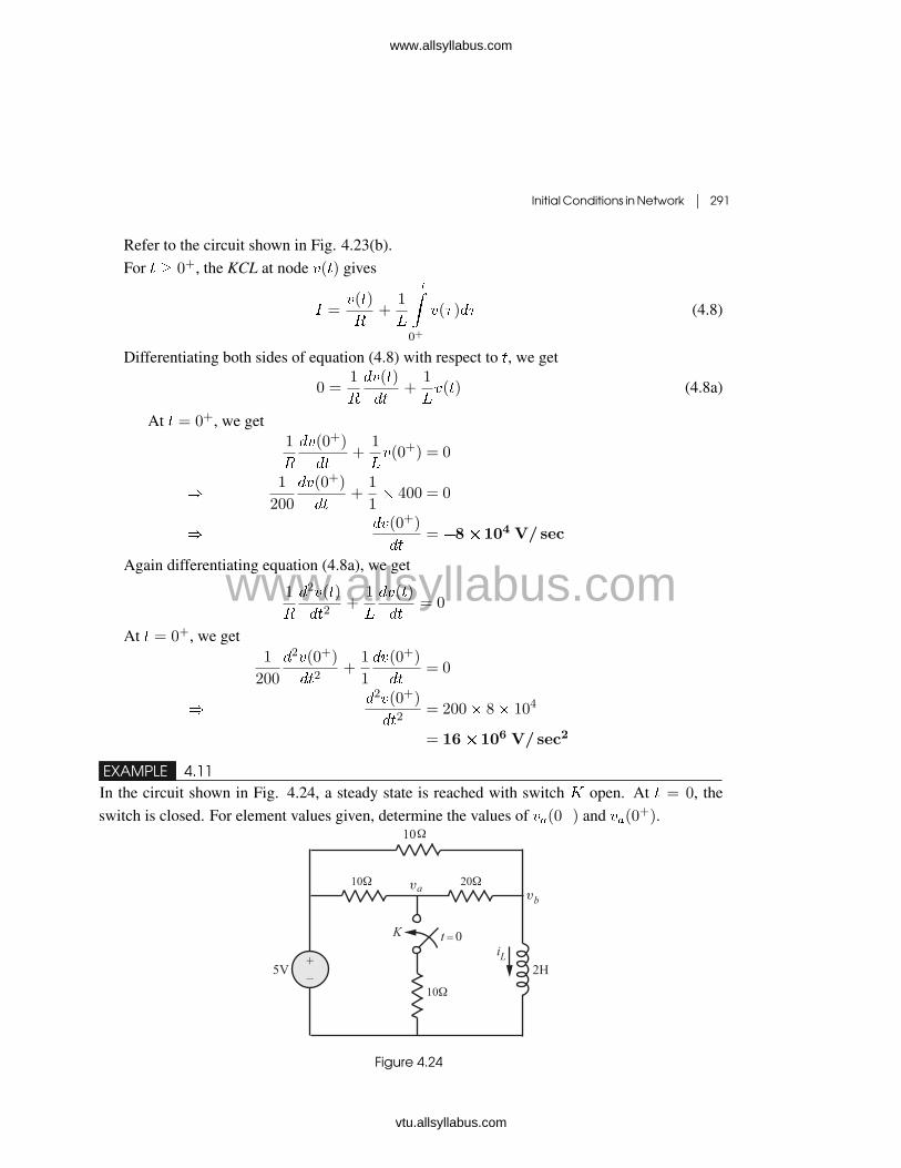
EXAMPLE 4.11In the circuit shown in Fig. 4.24, a steady state is reached with switch � open. At � = 0, theswitch is closed. For element values given, determine the values of ��(0�) and ��(0+).
Figure 4.24
www.allsyllabus.com
vtu.allsyllabus.com
www.allsyllabus.com

292 � Network Theory
SOLUTION
At � = 0�, the switch is open and at � = 0+, the switch is closed. Under steady conditions,inductor � acts as a short circuit. Also the steady state is reached with switch � open. Hence, thecircuit diagram at � = 0� is as shown in Fig.4.25(a).
��(0�) =
5
30+
5
10=
2
3A
Using the voltage divider principle:
��(0�) =
5� 20
10 + 20=
10
3V
Since the current in an inductor cannot change instantaneously,
��(0+) = ��(0
�) =2
3A�
At � = 0+, the circuit diagram is as shown in Fig. 4.25(b).
Figure 4.25(a) Figure 4.25(b)
Refer the circuit in Fig. 4.25(b).KCL at node a:
��(0+)� 5
10+
��(0+)
10+
��(0+)� ��(0
+)
20= 0
� ��(0+)
�1
10+
1
10+
1
20
�� ��(0
+)
�1
20
�=
5
10
KCL at node b:
��(0+)� ��(0
+)
20+
��(0+)� 5
10+
2
3= 0
� ���(0+)
�1
20
�+ ��(0
+)
�1
20+
1
10
�=
5
10�
2
3
www.allsyllabus.com
vtu.allsyllabus.com
www.allsyllabus.com
Initial Conditions in Network � 293
Solving the above two nodal equations, we get,
��(0+) =
40
21V
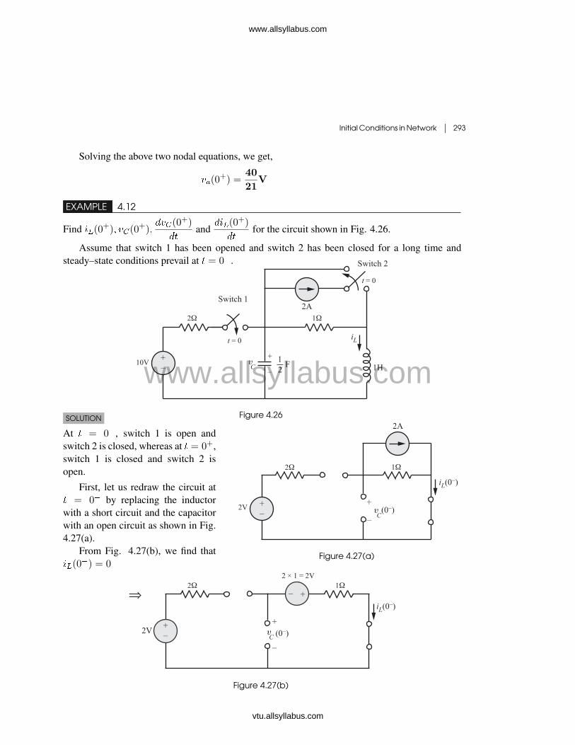
EXAMPLE 4.12
Find ��(0+)� ��(0+)����(0
+)
��and
���(0+)
��for the circuit shown in Fig. 4.26.
Assume that switch 1 has been opened and switch 2 has been closed for a long time andsteady–state conditions prevail at � = 0�.
Figure 4.26
Figure 4.27(a)
SOLUTION
At � = 0�, switch 1 is open andswitch 2 is closed, whereas at � = 0+,switch 1 is closed and switch 2 isopen.
First, let us redraw the circuit at� = 0� by replacing the inductorwith a short circuit and the capacitorwith an open circuit as shown in Fig.4.27(a).
From Fig. 4.27(b), we find that��(0
�) = 0
Figure 4.27(b)
www.allsyllabus.com
vtu.allsyllabus.com
www.allsyllabus.com

294 � Network Theory
Applying KVL clockwise to the loop on theright, we get
���(0�)� 2 + 1� 0 = 0
� ��(0�) = �2 V
Hence, at � = 0+ : ��(0+) = ��(0
�) = 0A
��(0+) = ��(0
�) = �2V
The circuit diagram for � � 0+ is shown inFig. 4.27(c). Figure 4.27(c)
Applying KVL for right–hand mesh, we get
�� � �� + �� = 0
At � = 0+, we get
��(0+) = ��(0
+)� ��(0+)
= �2� 0 = �2 V
We know that �� = ������
At � = 0+, we get
���(0+)
��=
��(0+)
�=�2
1= �2A/ sec
Applying KCL at node � ,�� � 10
2+ �� + �� = 0
Consequently, at � = 0+
��(0+) =
10� ��(0+)
2� ��(0
+) = 6� 0 = 6 A
Since �� = �����
We get,���(0
+)
��=
��(0+)
=
612
= 12V/ sec
EXAMPLE 4.13For the circuit shown in Fig. 4.28, find:
(a) �(0+) and �(0+)
(b)��(0+)
��and
��(0+)
��
(c) �(�) and �(�)
www.allsyllabus.com
vtu.allsyllabus.com
www.allsyllabus.com

Initial Conditions in Network � 295
Figure 4.28SOLUTION
(a) From the symbol of switch, we find that at � = 0�, the switch is closed and � = 0+, it isopen. At � = 0�, the circuit has reached steady state so that the equivalent circuit is as shown inFig.4.29(a).
�(0�) =12
6= 2A
�(0�) = 12 V
Therefore, we have �(0+) = �(0�)
= 2A
�(0+) = �(0�) = 12V
(b) For � � 0+, we have the equivalent circuit as shown in Fig.4.29(b).
Figure 4.29(a) Figure 4.29(b)
Applying KVL anticlockwise to the mesh on the right, we get
��(�)� �(�) + 10�(�) = 0
Putting � = 0+, we get
��(0+)� �(0+) + 10�(0+) = 0
� ��(0+)� 12 + 10� 2 = 0
� ��(0+) = �8V
www.allsyllabus.com
vtu.allsyllabus.com
www.allsyllabus.com

296 � Network Theory
The voltage across the inductor is given by
�� = ���
��
� ��(0+) = �
��(0+)
��
���(0+)
��=
1
���(0
+)
=1
10(�8) = �0.8A/ sec
Similarly, the current through the capacitor is
Figure 4.29(c)
�� = ��
��
or��(0+)
��=
��(0+)
=��(0+)
=�2
10� 10�6= �0.2� 106V/ sec
(c) As � approaches infinity, the switch is open and the circuithas attained steady state. The equivalent circuit at � = � isshown in Fig.4.29(c).
�(�) = 0
�(�) = 0
EXAMPLE 4.14Refer the circuit shown in Fig.4.30. Find the following:
(a) �(0+) and �(0+)
(b)��(0+)
��and
��(0+)
��
(c) �(�) and �(�)
Figure 4.30
SOLUTION
From the definition of step function,
�(�) =
�1� � � 00� � � 0
www.allsyllabus.com
vtu.allsyllabus.com
www.allsyllabus.com

Initial Conditions in Network � 297
From Fig.4.31(a), �(�) = 0 at � = 0�.
Similarly� �(��) =
�1� �� � 00� �� � 0
or �(��) =
�1� � � 00� � � 0
From Fig.4.31(b), we find that �(��) = 1, at � = 0�.
������
������
Figure 4.31(a) Figure 4.31(b)
Due to the presence of �(��) and �(�) in the circuit of Fig.4.30, the circuit is an implicitswitching circuit. We use the word implicit since there are no conventional switches in the circuitof Fig.4.30.
The equivalent circuit at � = 0� is shown in Fig.4.31(c). Please note that at � = 0�, theindependent current source is open because �(�) = 0 at � = 0� and the circuit is in steady state.
Figure 4.31(c)
�(0�) =40
3 + 5= 5A
�(0�) = 5�(0�) = 25V
Therefore �(0+) = �(0�) = 5A
�(0+) = �(0�) = 25V
(b) For � � 0+� �(��) = 0. This implies that the independent voltage source is zero and henceis represented by a short circuit in the circuit shown in Fig.4.31(d).
www.allsyllabus.com
vtu.allsyllabus.com
www.allsyllabus.com

298 � Network Theory
Figure 4.31(d)
Applying KVL at node �, we get4 + � =
��
��+
�
5
At � = 0+, We get4 + �(0+) =
��(0+)
��+
�(0+)
5
� 4 + 5 = 0�1��(0+)
��+
25
5
���(0+)
��= 40V/ sec
Applying KVL to the left–mesh, we get
3�+ 0�25��
��+ � = 0
Evaluating at � = 0+, we get
3�(0+) + 0�25��(0+)
��+ �(0+) = 0
� 3� 5 + 0�25��(0+)
��+ 25 = 0
���(0+)
��=�4014
= �160A/ sec
(c) As � approaches infinity, again the circuit is in steady state. The equivalent circuit at � =�is shown in Fig.4.31(e).
Figure 4.31(e)
www.allsyllabus.com
vtu.allsyllabus.com
www.allsyllabus.com

Initial Conditions in Network � 299
Using the principle of current divider, we get
�(�) = �
�4� 5
3 + 5
�= �2.5A
�(�) = (�(�) + 4) 5
= (�2�5 + 4)5
= 7.5V
EXAMPLE 4.15Refer the circuit shown in Fig.4.32. Find the following:
(a) �(0+) and �(0+)
(b)��(0+)
��and
��(0+)
��
(c) �(�) and �(�)
Figure 4.32
SOLUTION
Here the function �(�) behaves like a switch. Mathematically,
�(�) =
�1� � � 00� � � 0
The above expression means that the switch represented by �(�) is open for � � 0 and remainsclosed for � � 0. Hence, the circuit diagram of Fig.4.32 may be redrawn as shown in Fig.4.33(a).
Figure 4.33(a)
For � � 0, the circuit is not active because switch is in open state, This implies that all theinitial conditions are zero.
That is, ��(0�) = 0 and ��(0�) = 0
for � � 0+, the equivalent circuit is as shown in Fig.4.33(b).
www.allsyllabus.com
vtu.allsyllabus.com
www.allsyllabus.com

300 � Network Theory
Figure 4.33(b)
From the circuit diagram of Fig.4.33(b), we find that� =
��5
At � = 0+, we get
�(0+) =��(0
+)
5=
��(0�)
5=
0
5= 0A
Also � = 15��
Evaluating at � = 0+, we get�(0+) = 15��(0
+)
= 15��(0�) = 15� 0 = 0V
(b) The equivalent circuit at � = 0+ is shown in Fig.4.33(c).We find from Fig.4.33(c) that
��(0+) = 5A
Figure 4.33(c)
From Fig.4.33(b), we can write�� = 5�
������
= 5��
��
Multiplying both sides by , we get
�����
= 5��
��
www.allsyllabus.com
vtu.allsyllabus.com
www.allsyllabus.com

Initial Conditions in Network � 301
� �� = 5��
��
Putting � = 0+, we get
��(0+)
��=
1
5��(0
+)
=1
5�14
� � 5
= 4A/ sec
Also � = 15��
���
��= 15
�����
���
��= 15
�1�
�����
�
���
��= 15��
At � = 0+, we find that
���(0+)
��= 15��(0
+)
From Fig.4.33(b), we find that ��(0+) = 0
Hence���(0+)
��= 15� 0
= 0V/ sec
EXAMPLE 4.16In the circuit shown in Fig. 4.34, steady state is reached with switch � open. The switch is closedat � = 0.
Determine: �1� �2���1��
and��2��
at � = 0+
Figure 4.34
www.allsyllabus.com
vtu.allsyllabus.com
www.allsyllabus.com
302 � Network Theory
SOLUTION
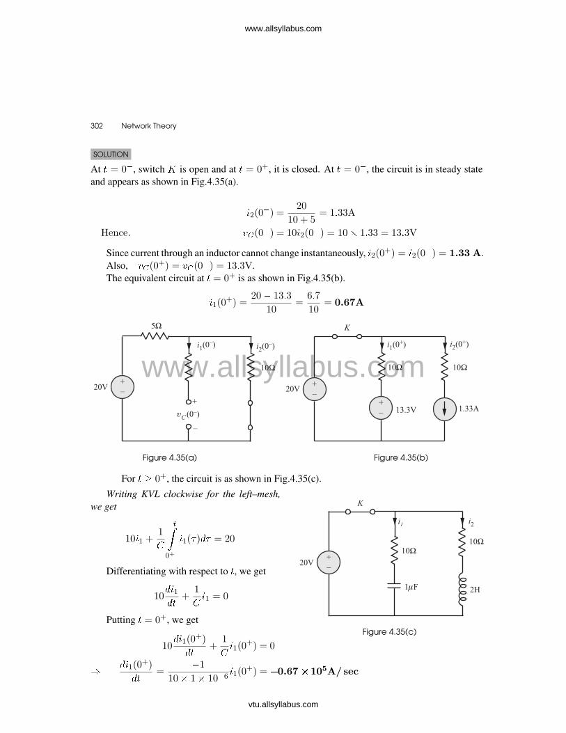
At � = 0�, switch � is open and at � = 0+, it is closed. At � = 0�, the circuit is in steady stateand appears as shown in Fig.4.35(a).
�2(0�) =
20
10 + 5= 1�33A
Hence� ��(0�) = 10�2(0
�) = 10� 1�33 = 13�3V
Since current through an inductor cannot change instantaneously, �2(0+) = �2(0�) = 1.33 A.
Also, ��(0+) = ��(0
�) = 13�3V.The equivalent circuit at � = 0+ is as shown in Fig.4.35(b).
�1(0+) =
20� 13�3
10=
6�7
10= 0.67A
Figure 4.35(a) Figure 4.35(b)
For � � 0+, the circuit is as shown in Fig.4.35(c).
Figure 4.35(c)
Writing KVL clockwise for the left–mesh,we get
10�1 +1
��0+
�1(� )�� = 20
Differentiating with respect to �, we get
10��1��
+1
�1 = 0
Putting � = 0+, we get
10��1(0
+)
��+
1
�1(0
+) = 0
���1(0
+)
��=
�1
10� 1� 10�6�1(0
+) = �0.67� 105A/ sec
www.allsyllabus.com
vtu.allsyllabus.com
www.allsyllabus.com

Initial Conditions in Network � 303
Writing KVL equation to the path made of 20V� � � 10Ω� 2H, we get
10�2 +2��2��
= 20
At � = 0+, the above equation becomes
10�2(0+) +
2��2(0+)
��= 20
� 10� 1�33 +2��2(0
+)
��= 20
���2(0
+)
��= 3.35A/ sec
EXAMPLE 4.17Refer the citcuit shown in Fig.4.36. The switch � is closed at � = 0. Find:
(a) �1 and �2 at � = 0+
(b) �1 and �2 at � =�
(c)��1��
and��2��
at � = 0+
(d)�2�1��2
at � = 0+
Figure 4.36SOLUTION
(a) The circuit symbol for switch conveys that at � = 0�, the switch is open and � = 0+, it isclosed. At � = 0�, since the switch is open, the circuit is not activated. This implies thatall initial conditions are zero. Hence, at � = 0+, inductor is open and capactor is short.Fig 4.37(a) shows the equivalent circuit at � = 0+.
Figure 4.37(a)
www.allsyllabus.com
vtu.allsyllabus.com
www.allsyllabus.com

304 � Network Theory
�1(0+) =
10
10= 1A
�1(0+) = 0� �2(0
+) = 0
Applying KVL to the path, 10V source� � � 10Ω� 10Ω� 2mH, we get
�10 + 10�1(0+) + �1(0
+) + �2(0+) = 0
� � 10 + 10 + 0 + �2(0+) = 0
� �2(0+) = 0
(b) At � = �, switch � remains closed and circuit is in steady state. Under steady stateconditions, capacitor is open and inductor � is short. Fig. 4.37(b) shows the equivalentcircuit at � =�.
�2(�) =10
10 + 10= 0.5A
�1(�) = 0
�1(�) = 0�5� 10 = 5V
�2(�) = 0
Figure 4.37(b)
(c) For � � 0+, the circuit is as shown in Fig. 4.37(c).
Figure 4.37(c)
www.allsyllabus.com
vtu.allsyllabus.com
www.allsyllabus.com

Initial Conditions in Network � 305
�2 =1
�
��0+
�2(� )�� =�1(�)
�2
Differentiating with respect to �, we get
�2�
=1
�2
��1��
Evaluating at � = 0+ we get
��1(0+)
��=
�2
�2�2(0
+)
���1(0
+)
��= 0V/ sec
Applying KVL clockwise to the path 10 V source� � � 10Ω� 4�F, we get
�10 + 10�+1
��0+
[�(� )� �2(� )]�� = 0
Differentiating with respect to �, we get
10��
��+
1
[�� �2] = 0
Evaluating at � = 0+, we get
��(0+)
��=
�2(0+)� �(0+)
� 10
=0� 1
10� 4� 10�6
∵ �(0+) = �1(0
+) + �2(0+)
= 1 + 0= 1A
��
= �25000A/ sec
Applying KVL clockwise to the path 10 V source� � � 10Ω� 10Ω� 2 mH,we get
�10 + 10�+ 10�2 + �2 = 0
� 10�+ �1 + �2 = 10
Differentiating with respect to �, we get
10��
��+
��1��
+��2��
= 0
www.allsyllabus.com
vtu.allsyllabus.com
www.allsyllabus.com

306 � Network Theory
At � = 0+, we get
10��(0+)
��+
��1(0+)
��+
��2(0+)
��= 0
� 10(�25000) + 0 +��2(0
+)
��= 0
���2(0
+)
��= 25� 104V/ sec
(d) From part (c), we have
1
�
��0+
�2(� )�� =�110
Differentiating with respect to � twice, we get
1
�
��2��
=1
10
�2�1��2
At � = 0+, we get
1
�
��2(0+)
��=
1
10
�2�1(0+)
��2
Hence��2�1(0
+)
��2= 125� 107V/ sec2
EXAMPLE 4.18Refer the network shown in Fig. 4.38. Switch � is changed from � to � at � = 0 (a steady statehaving been established at position �).
Figure 4.38
Show that at � = 0+.
�1 = �2 =�
�1 +�2 +�3� �3 = 0
www.allsyllabus.com
vtu.allsyllabus.com
www.allsyllabus.com
Initial Conditions in Network � 307
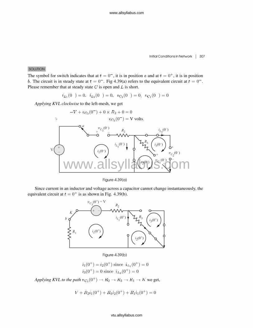
SOLUTION
The symbol for switch indicates that at � = 0�, it is in position � and at � = 0+, it is in position�. The circuit is in steady state at � = 0�. Fig 4.39(a) refers to the equivalent circuit at � = 0�.Please remember that at steady state is open and � is short.
��1(0�) = 0� ��2(0
�) = 0� ��2(0�) = 0� ��1(0
�) = 0
Applying KVL clockwise to the left-mesh, we get
� + ��3(0�) + 0��2 + 0 = 0
� ��3(0�) = V volts�
Figure 4.39(a)
Since current in an inductor and voltage across a capacitor cannot change instantaneously, theequivalent circuit at � = 0+ is as shown in Fig. 4.39(b).
Figure 4.39(b)
�1(0+) = �2(0
+) since ��1(0+) = 0
�3(0+) = 0 since ��2(0
+) = 0
Applying KVL to the path ��3(0+)� �2 � �3 � �1 � � we get,
+�2�1(0+) +�3�2(0
+) +�1�1(0+) = 0
www.allsyllabus.com
vtu.allsyllabus.com
www.allsyllabus.com

308 � Network Theory
Since �1(0+) = �2(0+), the above equation becomes
� = [�1 +�2 +�3] �1(0+)
Hence� �1(0+) = �2(0
+) =�V
R1 +R2 +R3A
EXAMPLE 4.19Refer the circuit shown in Fig. 4.40. The switch � is closed at � = 0.
Find (a)��1(0
+)
��and (b)
��2(0+)
��
Figure 4.40
SOLUTION
The circuit symbol for the switch shows that at� = 0�, it is open and at � = 0+, it is closed.Hence, at � = 0�, the circuit is not activated.This implies that all initial conditions are zero.That is, ��(0�) = 0 and ��(0
�) = �2(0�) = 0.
The equivalent circuit at � = 0+ keeping in mindthat ��(0+) = ��(0
�) and ��(0+) = ��(0
�) isas shown in Fig. 4.41 (a).
�1(0+) = 0 and �2(0
+) = 0�
Figure 4.41(a)
Figure. 4.41(b) shows the circuit diagram for � � 0+.
� sin�� = �1�+1
��0+
�1(� )��
Differentiating with respect to �, we get
�� cos�� = ���1��
+�1
www.allsyllabus.com
vtu.allsyllabus.com
www.allsyllabus.com

Initial Conditions in Network � 309
At � = 0+, we get
�� = ���1(0
+)
��+
�1(0+)
���1(0
+)
��=
V0ω
RA/ sec
Also� � sin�� = �2�+ ���2��
Evaluating at � = 0+, we get
0 = �2(0+)�+ �
��2(0+)
��
���2(0
+)
��= 0A/ sec
Figure 4.41(b)
EXAMPLE 4.20In the network of the Fig. 4.42, the switch � is opened at � = 0 after the network has attainedsteady state with the switch closed.
(a) Find the expression for �� at � = 0+.
(b) If the parameters are adjusted such that �(0+) = 1, and��(0+)
��= �1, what is the value of
the derivative of the voltage across the switch at � = 0+,������
(0+)
�?
Figure 4.42
SOLUTION
At � = 0�, switch is in the closed state and at� = 0+, it is open. Also at � = 0�, the circuitis in steady state. The equivalent circuit at� = 0� is as shown in Fig. 4.43(a).
�(0�) =
�2and ��(0
�) = 0
Figure 4.43(a)
www.allsyllabus.com
vtu.allsyllabus.com
www.allsyllabus.com

310 � Network Theory
For � � 0+, the equivalent circuit is as shown in Fig. 4.43(b).From Fig. 4.43 (b),
�� = �1�+1
��0+
�(� )��
� �� = �1�+ ��(�)
At � = 0+, ��(0+) = �1�(0+) + ��(0
+)
� ��(0+) = �1
�2+ ��(0
�)
=R1V
R2volts
Figure 4.43(b)
(b)
�� = �1�+1
��0+
�(� )��
������
= �1��
��+
�
Evaluating at � = 0+, we get
���(0+)
��= �1
��(0+)
��+
�(0+)
= �1 � (�1) +1
=1
C�R1volts/ sec
www.allsyllabus.com
vtu.allsyllabus.com
www.allsyllabus.com

Initial Conditions in Network � 311
Reinforcement Problems
R.P 4.1
Refer the circuit shown in Fig RP.4.1(a). If the switch is closed at � = 0, find the value of
�2��(0+)
��2at � = 0+.
Figure R.P.4.1(a)
SOLUTION
The circuit at � = 0� is as shown in Fig RP 4.1(b).Since current through an inductor and voltage across a capacitor cannot change
instantaneously, it implies that ��(0+) = 18A and ��(0+) = �180 V.The circuit for � � 0+ is as shown in Fig. RP 4.1 (c).
Figure R.P.4.1(b) Figure R.P.4.1(c)
Referring Fig RP 4.1 (c), we can write
2� 10�3�����
+ 60�� + 288� 103��
0+
��(�)�� = 0 (4.9)
www.allsyllabus.com
vtu.allsyllabus.com
www.allsyllabus.com

312 � Network Theory
At � = 0+, we get
���(0+)
��=�60� 18 + 180
2� 10�3
= �450� 103 A� sec
Differentiating equation (4.9) with respect to �, we get
2� 10�3�2����2
+ 60�����
+ 288� 103�� = 0
At � = 0+, we get
�2��(0+)
��2=
60(450)103 � 288� 103(18)
2� 10�3
= 1�0908� 1010 A� sec2
R.P 4.2
For the circuit shown in Fig. RP 4.2, determine�2��(0
+)
��2and
�3��(0+)
��3�
Figure R.P.4.2
SOLUTION
Given
�(�) = 2�(�) =
�2� � � 0+
0� � � 0�
Hence, at � = 0�, ��(0�) = 0 and ��(0�) = 0.For � � 0+, the circuit equations are
1
64
���(�)
��+
1
2
��0+
��(�)�� = �2 (4.10)
�1
64
���(�)
��+ ��(�) = �2 (4.11)
www.allsyllabus.com
vtu.allsyllabus.com
www.allsyllabus.com

Initial Conditions in Network � 313
[Note : �� + �� = �2 because of the capacitor polarity]
At � = 0+, equation (4.10) gives
1
64
���(0+)
��+ ��(0
+) = �2
Since, ��(0+) = ��(0�) = 0, we get
1
64
���(0+)
��+ 0 = �2
����(0
+)
��= �128 volts� sec
Differentiating equation (4.10) with respect to � we get
1
64
�2��(�)
��+
1
2��(�) = 0 (4.12)
Also��� � ��
24=
1
2
��0+
���� = �� (4.13)
At � = 0+, we get��(0
+)� ��(0+)
24= ��(0
+)
Since ��(0+) = 0 and ��(0+) = 0, we get ��(0+) = 0.
At � = 0+, equation (4.12) becomes
1
64
�2��(0+)
��2+
1
2��(0
+) = 0
�1
64
�2��(0+)
��2+
1
2� 0 = 0
��2��(0
+)
��2= 0
Differentiating equation (4.12) with respect to � we get
�1
64
�3����3
+1
2
�����
= 0 (4.14)
Differentiating equation (4.13) with respect to �, we get
������
�����
24=
1
2��
www.allsyllabus.com
vtu.allsyllabus.com
www.allsyllabus.com

314 � Network Theory
At � = 0+, we get
�
���(0+)
���
���(0+)
��24
=1
2��(0
+)
��128�
���(0+)
��24
= 0
����(0
+)
��= �128 volts� sec
At � = 0+, equation (4.14) becomes
1
64
�3��(0+)
��3+
1
2
���(0+)
��= 0
��3��(0
+)
��3= 4096 volts� sec3
R.P 4.3
In the network of Fig RP 4.3 (a), switch � is closed at � = 0. At � = 0� all the capacitor voltagesand all the inductor currents are zero. Three node-to-datum voltages are identified as �1, �2 and�3. Find at � = 0+:
(i) �1, �2 and �3
(ii)��1��
,��2��
and��3��
Figure R.P.4.3(a)
SOLUTION
The network at � = 0+ is as shown in Fig RP-4.3 (b).Since �� and �� cannot change instantaneously, we have from the network shown in
Fig. RP-4.3 (b),�1(0
+) = 0
�2(0+) = 0
�3(0+) = 0
www.allsyllabus.com
vtu.allsyllabus.com
www.allsyllabus.com

Initial Conditions in Network � 315
Figure R.P.4.3(b)
For � � 0+, the circuit equations are
��1 =1
1
��0+
�1��
��2 =1
2
��0+
�2��
��3 =1
3
��0+
�3��
����������������������������
(4.15)
From Fig. RP-4.3 (b), we can write
�1(0+) =
�(0+)
�1�
�2(0+) =
�1(0+)� �2(0
+)
�2
and �3(0+) = 0
Differentiating equation (4.15) with respect to �, we get
���1
��=
�11
����2
��=
�22
and���3
��=
�33
At � = 0+, the above equations give
��1(0+)
��=
�1(0+)
1=
�(0+)
�11
��2(0+)
��=
�2(0+)
2=
�1(0+)� �2(0
+)
�22= 0
and��3(0
+)
��=
�3(0+)
3= 0
www.allsyllabus.com
vtu.allsyllabus.com
www.allsyllabus.com

316 � Network Theory
R.P 4.4
For the network shown in Fig RP 4.4 (a) with switch � open, a steady-state is reached. The circuitpaprameters are �1 = 10Ω, �2 = 20Ω, �3 = 20Ω, � = 1 H and = 1�F. Take = 100volts. The switch is closed at � = 0.
(a) Write the integro-differentialequation after the switch isclosed.
(b) Find the voltage � across be-fore the switch is closed and giveits polarity.
(c) Find �1 and �2 at � = 0+.
(d) Find��1��
and��2��
at � = 0+.
(e) What is the value of��1��
at� =�?
Figure R.P.4.4(a)
SOLUTION
The switch is in open state at � = 0�. The network at � = 0� is as shown in Fig RP 4.4 (b).
Figure R.P.4.4(b)
�1(0�) =
�1 +�2=
100
30=
10
3A
�(0�) = �1(0
�)�2 =10
3� 20 =
200
3volts
Note that � is short and is open under steady-state condition.For � � 0+ (switch in closed state),
we have 20�1 +��1��
= 100 (4.16)
and 20�2 + 106��
0+
�2�� = 100 (4.17)
www.allsyllabus.com
vtu.allsyllabus.com
www.allsyllabus.com
Initial Conditions in Network � 317
Also �1(0+) = �1(0
�) =10
3A
and �(0+) = �(0
�) =200
3Volts
From equation (4.16) at � = 0+,
we have��1(0
+)
��= 100� 20�
10
3
=100
3A�sec
From equation (4.17), at � = 0+, we have
�2(0+) =
1
20
�100�
200
3
�=
5
3A
Differentiating equation (4.17), we get
20��2��
+ 106�2 = 0 (4.18)
From equation (4.18) at � = 0+, we get
20��2(0+)
��+ 106�2(0
+) = 0
���2(0
+)
��=�106 � 5
3
20
=�106
12A� sec
At � =�,
�1(�) =100
20= 5 A
��1��
(�) = 0
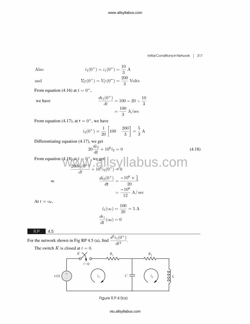
R.P 4.5
For the network shown in Fig RP 4.5 (a), find�2�1(0
+)
��2.
The switch � is closed at � = 0.
Figure R.P.4.5(a)
www.allsyllabus.com
vtu.allsyllabus.com
www.allsyllabus.com
318 � Network Theory
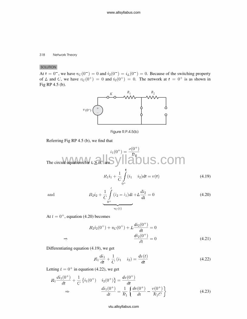
SOLUTION
At � = 0�, we have ��(0�) = 0 and �2(0�) = ��(0
�) = 0. Because of the switching propertyof � and , we have ��(0
+) = 0 and �2(0+) = 0. The network at � = 0+ is as shown in
Fig RP 4.5 (b).
Figure R.P.4.5(b)
Referring Fig RP 4.5 (b), we find that
�1(0+) =
�(0+)
�1
The circuit equations for � � 0+ are
�1�1 +1
��0+
(�1 � �2)�� = �(�) (4.19)
and �2�2 +1
��0+
(�2 � �1)��
� �� �C(�)
+���2��
= 0 (4.20)
At � = 0+, equation (4.20) becomes
�2�2(0+) + ��(0
+) + ���2(0
+)
��= 0
���2(0
+)
��= 0 (4.21)
Differentiating equation (4.19), we get
�1��1��
+1
(�1 � �2) =
��(�)
��(4.22)
Letting � = 0+ in equation (4.22), we get
�1��1(0
+)
��+
1
��1(0
+)� �2(0+)�=
��(0+)
��
���1(0
+)
��=
1
�1
���(0+)
���
�(0+)
�1
�(4.23)
www.allsyllabus.com
vtu.allsyllabus.com
www.allsyllabus.com

Initial Conditions in Network � 319
Differentiating equation (4.22) gives
�1�2�1��2
+1
���1���
��2��
�=
�2�(�)
��2
Letting � = 0+, we get
�1�2�1(0
+)
��2+
1
���1(0
+)
���
��2(0+)
��
�=
�2�(0+)
��2
� �1�2�1(0
+)
��2= �
1
��1(0+)
��+
�2�(0+)
��2
��2�1(0
+)
��2= �
1
�1
�1
�1
��(0+)
���
1
�21
�(0+)
�+
�2�(0+)
��2
R.P 4.6
Determine ��(0�) and ��(0+) for the network shown in Fig RP 4.6 (a). Assume that the switch
is closed at � = 0.
Figure R.P.4.6(a)
SOLUTION
Since� is short for DC at steady state, the net-work at � = 0� is as shown in Fig. RP 4.6 (b).
Applying KCL at junction �, we get
��(0�)� 5
10+
��(0�)� ��(0
�)
20= 0
Since ��(0�) = 0, we get
��(0�)� 5
10+
��(0�)� 0
20= 0
� ��(0�) =
0�5
0�1 + 0�05=
10
3volts
Figure R.P.4.6(b)
www.allsyllabus.com
vtu.allsyllabus.com
www.allsyllabus.com
320 � Network Theory
Also� ��(0�) = ��(0
+) =��(0
�)
20+
5
10
=2
3A
For � � 0+, we can write
�� � 5
10+
��10
+�� � ��
20= 0
and�� � ��
20+
�� � 5
10+ �� = 0
Simplifying at � = 0+, we get
1
4��(0
+)�1
20��(0
+) =1
2
and �1
20��(0
+) +3
20��(0
+) =�1
6
Solving we get, ��(0+) =
40
21= 1�905 volts
Exercise problems
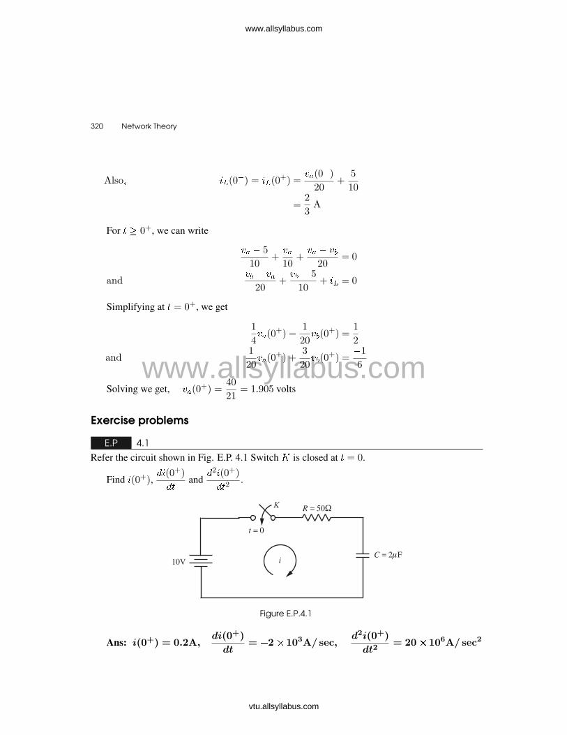
E.P 4.1
Refer the circuit shown in Fig. E.P. 4.1 Switch � is closed at � = 0.
Find �(0+),��(0+)
��and
�2�(0+)
��2.
Figure E.P.4.1
Ans: i(0+) = 0.2A,di(0+)
dt= �2� 103A/ sec,
d2i(0+)
dt2= 20� 106A/ sec2
www.allsyllabus.com
vtu.allsyllabus.com
www.allsyllabus.com

Initial Conditions in Network � 321
E.P 4.2
Refer the circuit shown in Fig. E.P. 4.2. Switch � is closed at � = 0. Find the values of ����
��and
�2�
��2at � = 0+.
Figure E.P.4.2
Ans: i(0+) = 0,di(0+)
dt= 10 A/ sec,
d2i(0+)
dt2= �1000 A/ sec2
E.P 4.3
Refering to the circuit shown in Fig. E.P. 4.3, switch is changed from position 1 to position 2 at
� = 0. The circuit has attained steady state before switching. Determine �,��
��and
�2�
��2at � = 0+.
Figure E.P.4.3
Ans: i(0+) = 0,di(0+)
dt= �40 A/ sec,
d2i(0+)
dt2= 800 A/ sec2
www.allsyllabus.com
vtu.allsyllabus.com
www.allsyllabus.com

322 � Network Theory
E.P 4.4
In the network shown in Fig. E.P.4.4, the initial voltage on 1 is � and on 2 is � such that
�1(0�) = � and �2(0�) = �. Find the values of
��1��
and��2��
at � = 0+.
Figure E.P.4.4
Ans:dv1(0+)
dt=
V� � V�C1R
V/ sec,dv2(0+)
dt=
V� � V�C2R
V/ sec
E.P 4.5
In the network shown in Fig E.P. 4.5, switch � is closed at � = 0 with zero capacitor voltage and
zero inductor current. Find�2�2��2
at � = 0+.
Figure E.P.4.5
Ans:d2v2(0+)
dt2=
R2V�R1L1C1
V/ sec2
www.allsyllabus.com
vtu.allsyllabus.com
www.allsyllabus.com
Initial Conditions in Network � 323
E.P 4.6
In the network shown in Fig. E.P. 4.6, switch � is closed at � = 0. Find�2�1��2
at � = 0+.
Figure E.P.4.6
Ans:d2v1(0+)
dt2= 0 V/ sec2
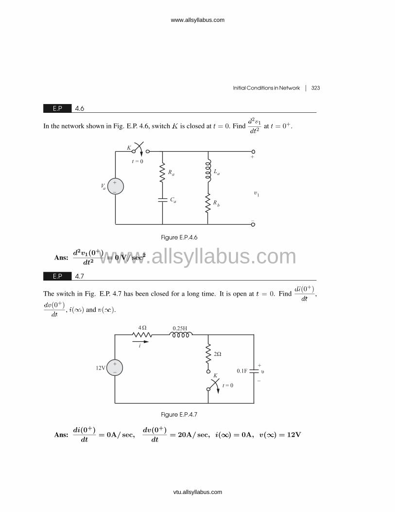
E.P 4.7
The switch in Fig. E.P. 4.7 has been closed for a long time. It is open at � = 0. Find��(0+)
��,
��(0+)
��, �(�) and �(�).
�
Figure E.P.4.7
Ans:di(0+)
dt= 0A/ sec,
dv(0+)
dt= 20A/ sec, i(�) = 0A, v(�) = 12V
www.allsyllabus.com
vtu.allsyllabus.com
www.allsyllabus.com

324 � Network Theory
E.P 4.8
In the circuit of Fig E.P. 4.8, calculate ��(0+),���(0
+)
��,���(0
+)
��, �(�), ��(�) and ��(�).
Figure E.P.4.8
Ans: i�(0+) = 0 A,di�(0+)
dt= 0 A/ sec
dv�(0+)
dt= 2 V/ sec, v�(�) = 4V, v�(�) = �20V, i�(�) = 1A
E.P 4.9
Refer the circuit shown in Fig. E.P. 4.9. Assume that the switch was closed for a long time for
� � 0. Find���(0
+)
��and ��(0+). Take �(0+) = 8 V.
Figure E.P.4.9
Ans: i�(0+) = 4 A,di�(0+)
dt= 0 A/ sec
E.P 4.10
Refer the network shown in Fig. E.P. 4.10. A steady state is reached with the switch � closed and
with � = 10A. At � = 0, switch � is opened. Find �2(0+) and��2(0
+)
��.
www.allsyllabus.com
vtu.allsyllabus.com
www.allsyllabus.com

Initial Conditions in Network � 325
Figure E.P.4.10
Ans: v2(0+) = 0,dv2(0+)
dt=
10R�R�
C�(R� +R�)(R� +R�)V� sec.
E.P 4.11
Refer the network shown in Fig. E.P. 4.11. The network is in steady state with switch � closed.
The switch is opened at � = 0. Find ��(0+) and���(0
+)
��.
Figure E.P.4.11
Ans: v�(0+) =V�R�
R� +R� +R�
Volts,
dv�(0+)
dt=
V�(C� +C�)
(R� +R� +R�)(C�C� +C�C� +C�C�)V/ sec
E.P 4.12
Refer the network shown in Fig. E.P. 4.12. Find�2�1(0
+)
��2.
www.allsyllabus.com
vtu.allsyllabus.com
www.allsyllabus.com

326 � Network Theory
Figure E.P.4.12
Ans:d2i1(0+)
dt2=
1
R�
��10 +
10
R2�C
2�
�A/ sec2
E.P 4.13
Refer the circuit shown in Fig. E.P. 4.13. Find��1(0
+)
��. Assume that the circuit has attained
steady state at � = 0�.
Figure E.P.4.13
Ans:di1(0+)
dt=
10
R
A/ sec
E.P 4.14
Refer the network shown in Fig. E.P.4.14. The circuit reaches steady state with switch � closed.
At a new reference time, � = 0, the switch � is opened. Find��1(0
+)
��and
�2�2(0+)
��2.
Figure E.P.4.14
www.allsyllabus.com
vtu.allsyllabus.com
www.allsyllabus.com

Initial Conditions in Network � 327
Ans:dv1(0+)
dt=
�10
C�(R� +R�)V/ sec,
d2v2(0+)
dt2=
�10R�
L�C�(R� +R�)V/ sec2
E.P 4.15
The switch shown in Fig. E.P. 4.15 has been open for a long time before closing at � = 0. Find:�0(0
�), ��(0�) �0(0+), ��(0+), �0(�), ��(�) and ��(�).
Figure E.P.4.15
Ans: i(0�) = 0, i�(0�) = 160mA, i0(0
+) = 65mA, i�(0+) = 160mA,
i0(�) = 225mA, i�(�) = 0, v�(�) = 0
E.P 4.16
The switch shown in Fig. E.P. 4.16 has been closed for a long time before opeing at � = 0.Find: �1(0�), �2(0�), �1(0+), �2(0+). Explain why �2(0�) = �2(0
+).
Figure E.P.4.16
Ans: i1(0�) = i2(0
�) = 0.2mA, i2(0+) = �i1(0
+) = �0.2mA
www.allsyllabus.com
vtu.allsyllabus.com
www.allsyllabus.com

328 � Network Theory
E.P 4.17
The switch in the circuit of Fig E.P.4.17 is closed at � = 0 after being open for a long time. Find:(a) �1(0�) and �2(0�)
(b) �1(0+) and �2(0+)
(c) Explain why �1(0�) = �1(0+)
(d) Explain why �2(0�) = �2(0+)
Figure E.P.4.17
Ans: i1(0�) = i2(0�) = 0.2 mA, i1(0+) = 0.2 mA, i2(0+) = �0.2mA
www.allsyllabus.com
vtu.allsyllabus.com
www.allsyllabus.com