Embed Size (px)
Citation preview
©John Parkinson
1
The Cathode Ray The Cathode Ray OscilloscopeOscilloscope
©John Parkinson
2
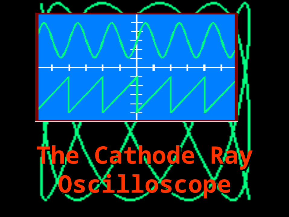
THE CATHODE RAY OSCILLOSCOPE
X DEFLECTIO
N
PLATES
Y DEFLECTIO
N
PLATESElectron Beam
Vacuum Fluorescent screen
electron
gun
©John Parkinson
3
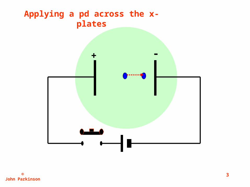
+ -
Applying a pd across the x-plates
©John Parkinson
4
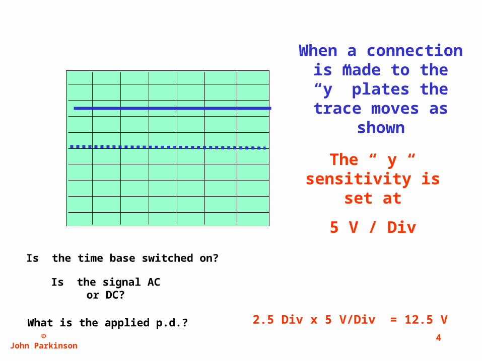
The “ y “ sensitivity is set at
5 V / Div
When a connection is made to the “y” plates
the trace moves as shown
Is the time base switched on?
Is the signal AC or DC?
What is the applied p.d.? 2.5 Div x 5 V/Div = 12.5 V
©John Parkinson
5
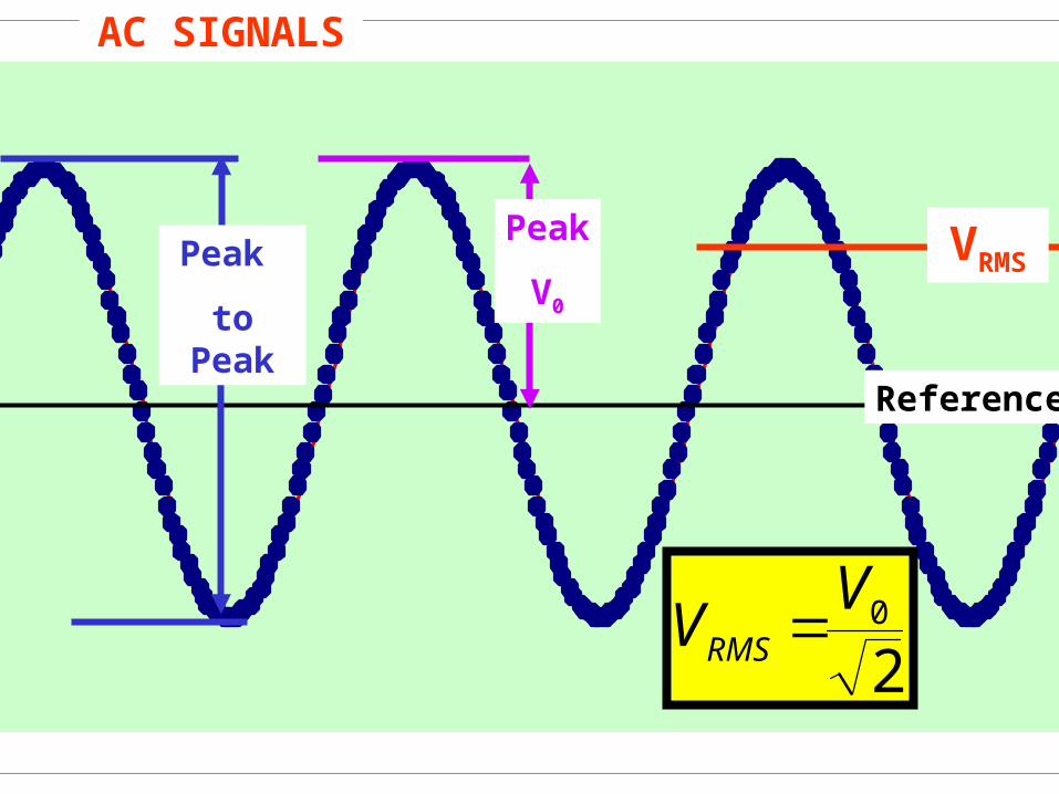
Reference
Peak
to Peak
Peak
V0
VRMS
20VVRMS
AC SIGNALS
©John Parkinson
6
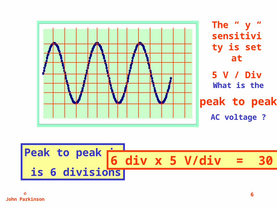
The “ y “ sensitivity
is set at
5 V / Div
What is the
peak to peak
AC voltage ?
Peak to peak is
is 6 divisions6 div x 5 V/div = 30 V
©John Parkinson
7
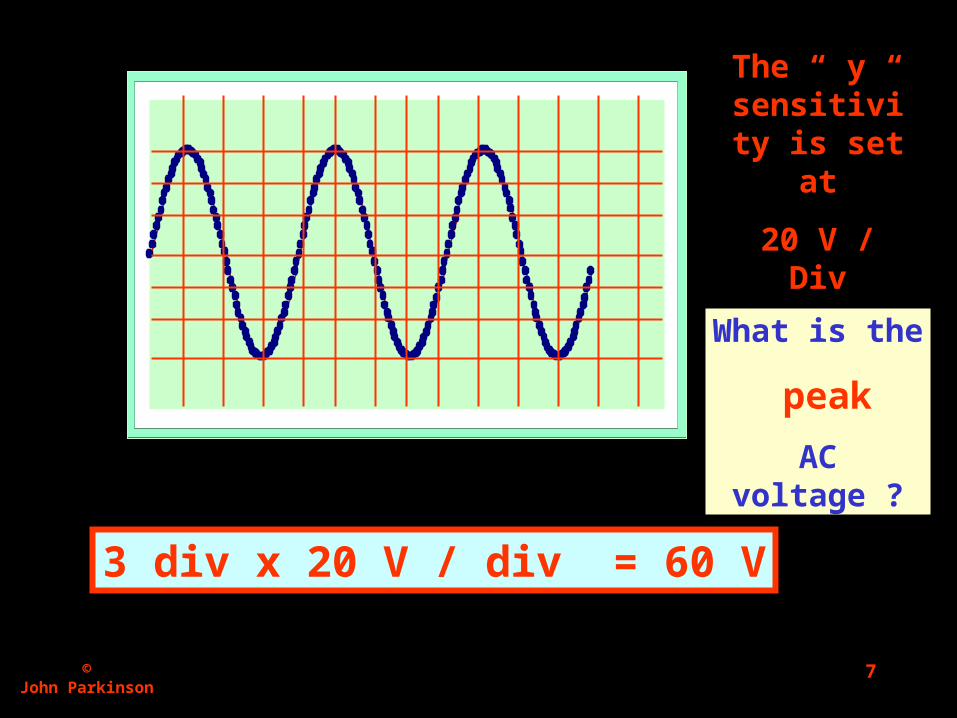
The “ y “ sensitivity
is set at
20 V / Div
What is the
peak
AC voltage ?
3 div x 20 V / div = 60 V
©John Parkinson
8
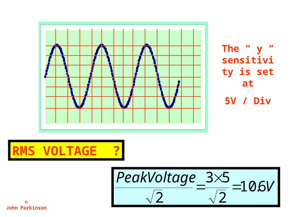
The “ y “ sensitivity
is set at
5V / Div
RMS VOLTAGE ?
VVoltagePeak
6.10253
2
©John Parkinson
9
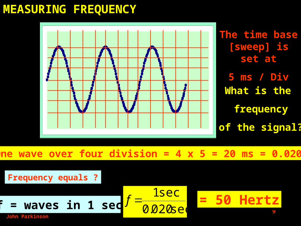
The time base [sweep] is set at
5 ms / Div
What is the
frequency
of the signal?
One wave over four division = 4 x 5 = 20 ms = 0.020 s
f = waves in 1 sec
Frequency equals ?
sec020.0sec1f = 50 Hertz
MEASURING FREQUENCY
©John Parkinson
10
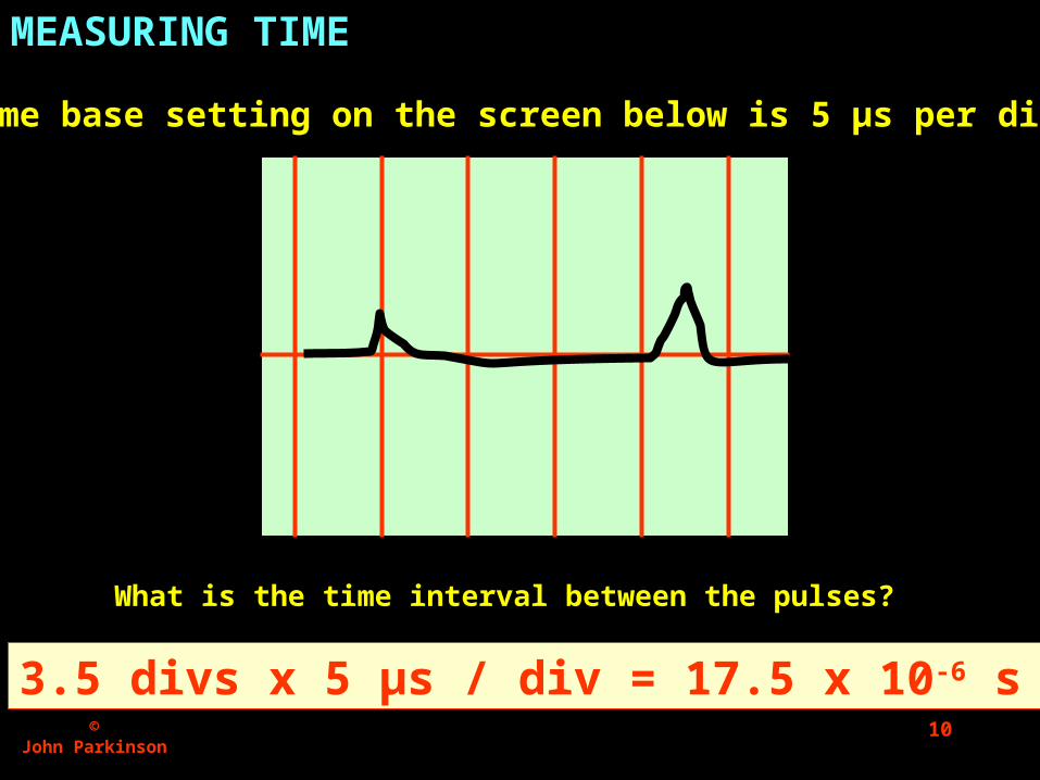
The time base setting on the screen below is 5 μs per division
What is the time interval between the pulses?
3.5 divs x 5 μs / div = 17.5 x 10⁻⁶ s
MEASURING TIME
©John Parkinson
11
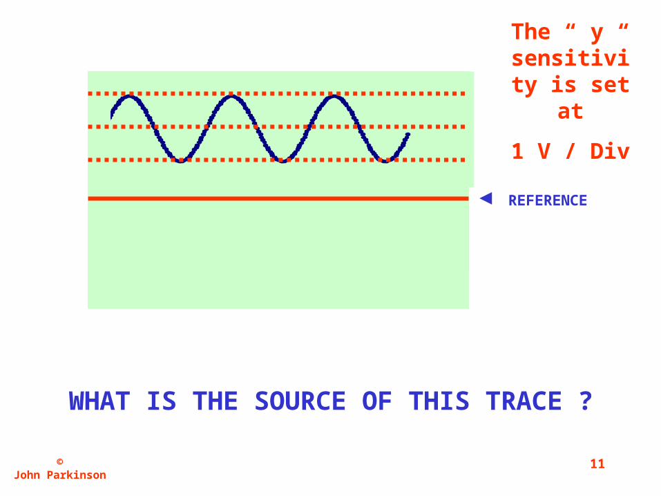
REFERENCE
The “ y “ sensitivity
is set at
1 V / Div
WHAT IS THE SOURCE OF THIS TRACE ?
©John Parkinson
12
JPSBC
10
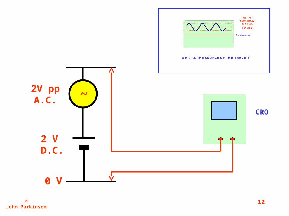
REFERENCE
The “ y “sensitivity
is set at
1 V / Div
WHAT IS THE SOURCE OF THIS TRACE ?
0 V
2 V D.C.
2V pp A.C. ~
CRO