Embed Size (px)
Citation preview
. . . . . . . . . . . . . . . . . . . . . . . . . . . . . . . . . . . . .. . . . .
Medalist 8641, Medalist 6531. . . . . . . . . . . . . . . . . . . . . . . . . . . . . . . . . . . . .. . . . .
Medalist 4321, Medalist 3221. . . . . . . . . . . . . . . . . . . . . . . . . . . . . . . . . . . . .
Medalist 2110. . . . . . . . . . . . . . . . . . . . . . . . . . . . . . . . . . . . .
Ultra ATA Interface Drives. . . . . . . . . . . . . . . . . . . . . . . . . . . . . . . . . . . . .. . . . .
Product Manual. . . . . . . . . . . . . . . . . . . . . . . . . . . . . . . . . . . . .. . . . .

. . . . . . . . . . . . . . . . . . . . . . . . . . . . . . . . . . . . .. . . . .
Medalist 8641, Medalist 6531 . . . . . . . . . . . . . . . . . . . . . . . . . . . . . . . . . . . . .. . . . .
Medalist 4321, Medalist 3221 . . . . . . . . . . . . . . . . . . . . . . . . . . . . . . . . . . . . .. . . . .
Medalist 2110 . . . . . . . . . . . . . . . . . . . . . . . . . . . . . . . . . . . . .. . . . .
Ultra ATA Interface Drives. . . . . . . . . . . . . . . . . . . . . . . . . . . . . . . . . . . . .. . . . .
Product Manual. . . . . . . . . . . . . . . . . . . . . . . . . . . . . . . . . . . . .. . . . .
1998, 1999 Seagate Technology, Inc. All rights reserved
Publication Number: 20400075-001, Rev. B, January 1999
Seagate, Seagate Technology, the Seagate logo, Medalist and theMedalist logo are registered trademarks of Seagate Technology, Inc.Other product names are registered trademarks or trademarks of theirowners.
Seagate reserves the right to change, without notice, product offeringsor specifications. No part of this publication may be reproduced in anyform without written permission from Seagate Technology, Inc.
Contents
Introduction . . . . . . . . . . . . . . . . . . . . . . . . . . . . 1
Specification summary table . . . . . . . . . . . . . . . . . . . 2
1.0 Drive specifications . . . . . . . . . . . . . . . . . . . . . . 5
1.1 Formatted capacity . . . . . . . . . . . . . . . . . . . . . 5
1.1.1 Default logical geometry . . . . . . . . . . . . . . . . 5
1.1.2 Supported CHS translation geometries . . . . . . . . 6
1.2 Physical organization . . . . . . . . . . . . . . . . . . . . 6
1.3 Recording and interface technology . . . . . . . . . . . . . 6
1.4 Physical characteristics . . . . . . . . . . . . . . . . . . . 7
1.5 Seek time . . . . . . . . . . . . . . . . . . . . . . . . . . 7
1.6 Start/stop times . . . . . . . . . . . . . . . . . . . . . . . 8
1.7 Power Specifications . . . . . . . . . . . . . . . . . . . . 8
1.7.1 Power consumption . . . . . . . . . . . . . . . . . . 8
1.7.2 Conducted noise . . . . . . . . . . . . . . . . . . . . 10
1.7.3 Voltage tolerance . . . . . . . . . . . . . . . . . . . . 10
1.7.4 Power-management modes . . . . . . . . . . . . . . 11
1.8 Environmental tolerances . . . . . . . . . . . . . . . . . . 12
1.8.1 Ambient temperature . . . . . . . . . . . . . . . . . . 12
1.8.2 Temperature gradient . . . . . . . . . . . . . . . . . 12
1.8.3 Humidity . . . . . . . . . . . . . . . . . . . . . . . . 12
1.8.4 Altitude . . . . . . . . . . . . . . . . . . . . . . . . . 12
1.8.5 Shock . . . . . . . . . . . . . . . . . . . . . . . . . . 12
1.8.6 Vibration . . . . . . . . . . . . . . . . . . . . . . . . 13
1.9 Drive acoustics . . . . . . . . . . . . . . . . . . . . . . . 14
1.10 Electromagnetic susceptibility . . . . . . . . . . . . . . . 14
1.11 Reliability . . . . . . . . . . . . . . . . . . . . . . . . . . 14
1.12 Agency certification . . . . . . . . . . . . . . . . . . . . 15
1.12.1 Safety certification . . . . . . . . . . . . . . . . . . 15
Medalist 8641, 6531, 4321, 3221 and 2110, Rev. B iii
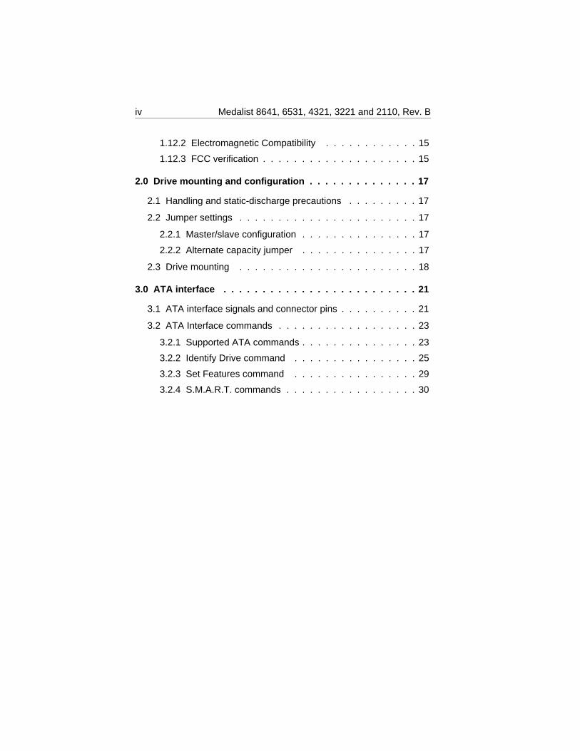
1.12.2 Electromagnetic Compatibility . . . . . . . . . . . . 15
1.12.3 FCC verification . . . . . . . . . . . . . . . . . . . . 15
2.0 Drive mounting and configuration . . . . . . . . . . . . . . 17
2.1 Handling and static-discharge precautions . . . . . . . . . 17
2.2 Jumper settings . . . . . . . . . . . . . . . . . . . . . . . 17
2.2.1 Master/slave configuration . . . . . . . . . . . . . . . 17
2.2.2 Alternate capacity jumper . . . . . . . . . . . . . . . 17
2.3 Drive mounting . . . . . . . . . . . . . . . . . . . . . . . 18
3.0 ATA interface . . . . . . . . . . . . . . . . . . . . . . . . . 21
3.1 ATA interface signals and connector pins . . . . . . . . . . 21
3.2 ATA Interface commands . . . . . . . . . . . . . . . . . . 23
3.2.1 Supported ATA commands . . . . . . . . . . . . . . . 23
3.2.2 Identify Drive command . . . . . . . . . . . . . . . . 25
3.2.3 Set Features command . . . . . . . . . . . . . . . . 29
3.2.4 S.M.A.R.T. commands . . . . . . . . . . . . . . . . . 30
iv Medalist 8641, 6531, 4321, 3221 and 2110, Rev. B
Figures
Figure 1. Typical startup and operation current profile . . . . . . . 10
Figure 2. Alternate capacity jumper and master/slave jumpers . . 18
Figure 3. Drive mounting dimensions—top, side and end view . . . 19
Figure 4. I/O pins and supported ATA signals . . . . . . . . . . . 22
Medalist 8641, 6531, 4321, 3221 and 2110, Rev. B v

vi Medalist 8641, 6531, 4321, 3221 and 2110, Rev. B
IntroductionThis manual describes the functional, mechanical and interface specifi-cations for the Medalist 8641 (ST38641A), Medalist 6531 (ST36531A),Medalist 4321 (ST34321A), Medalist 3221 (ST33221A) and Medalist2110 (ST32110A). These drives are referred to throughout this manualby their model numbers. These drives provide the following key features:
• Low power consumption
• Quiet operation
• Support for S.M.A.R.T. drive monitoring and reporting
• High instantaneous (burst) data-transfer rates (up to 33.3 Mbytes persecond) using Ultra DMA mode 2
• Full-track multiple-sector transfer capability without local processorintervention
• 128-Kbyte cache
• State-of-the-art caching and on-the-fly error-correction algorithms
• Support for Read Multiple and Write Multiple commands
• Support for autodetection of master/slave drives that use cable select(CSEL)
• MR recording heads and PRML technology, which provides the driveswith increased areal density
Medalist 8641, 6531, 4321, 3221 and 2110, Rev. B 1
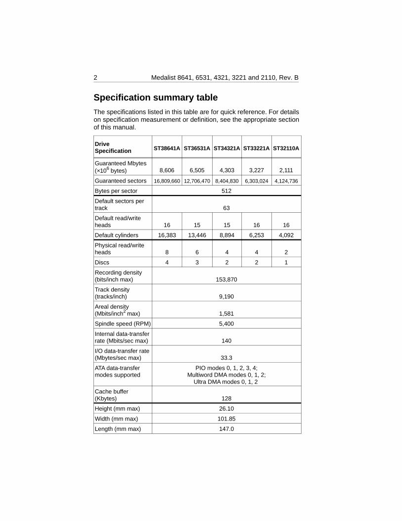
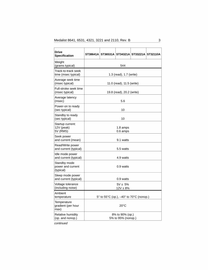
Specification summary tableThe specifications listed in this table are for quick reference. For detailson specification measurement or definition, see the appropriate sectionof this manual.
DriveSpecification ST38641A ST36531A ST34321A ST33221A ST32110A
Guaranteed Mbytes (×106 bytes) 8,606 6,505 4,303 3,227 2,111
Guaranteed sectors 16,809,660 12,706,470 8,404,830 6,303,024 4,124,736
Bytes per sector 512
Default sectors pertrack 63
Default read/writeheads 16 15 15 16 16
Default cylinders 16,383 13,446 8,894 6,253 4,092
Physical read/writeheads 8 6 4 4 2
Discs 4 3 2 2 1
Recording density(bits/inch max) 153,870
Track density(tracks/inch) 9,190
Areal density(Mbits/inch2 max) 1,581
Spindle speed (RPM) 5,400
Internal data-transferrate (Mbits/sec max) 140
I/O data-transfer rate (Mbytes/sec max) 33.3
ATA data-transfermodes supported
PIO modes 0, 1, 2, 3, 4;Multiword DMA modes 0, 1, 2;
Ultra DMA modes 0, 1, 2
Cache buffer(Kbytes) 128
Height (mm max) 26.10
Width (mm max) 101.85
Length (mm max) 147.0
2 Medalist 8641, 6531, 4321, 3221 and 2110, Rev. B
DriveSpecification ST38641A ST36531A ST34321A ST33221A ST32110A
Weight(grams typical) 544
Track-to-track seektime (msec typical) 1.3 (read), 1.7 (write)
Average seek time(msec typical) 11.0 (read), 11.5 (write)
Full-stroke seek time(msec typical) 19.8 (read), 20.2 (write)
Average latency(msec) 5.6
Power-on to ready(sec typical) 10
Standby to ready(sec typical) 10
Startup current:12V (peak)5V (RMS)
1.8 amps0.6 amps
Seek powerand current (mean) 9.1 watts
Read/Write powerand current (typical) 5.5 watts
Idle mode powerand current (typical) 4.9 watts
Standby modepower and current(typical)
0.9 watts
Sleep mode powerand current (typical) 0.9 watts
Voltage tolerance(including noise)
5V ± 5%12V ± 8%
Ambienttemperature 5° to 55°C (op.), –40° to 70°C (nonop.)
Temperature gradient (per hourmax)
20°C
Relative humidity(op. and nonop.)
8% to 90% (op.)5% to 95% (nonop.)
continued
Medalist 8641, 6531, 4321, 3221 and 2110, Rev. B 3
DriveSpecification ST38641A ST36531A ST34321A ST33221A ST32110A
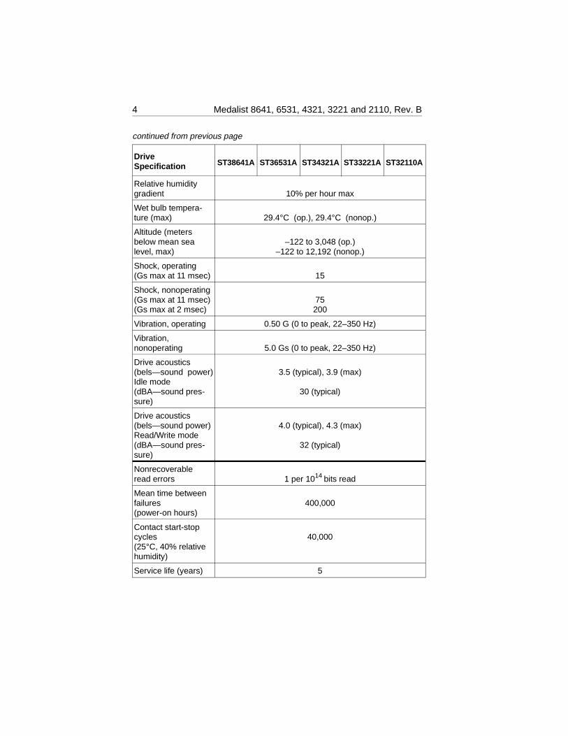
Relative humiditygradient 10% per hour max
Wet bulb tempera-ture (max) 29.4°C (op.), 29.4°C (nonop.)
Altitude (metersbelow mean sealevel, max)
–122 to 3,048 (op.)–122 to 12,192 (nonop.)
Shock, operating (Gs max at 11 msec) 15
Shock, nonoperating(Gs max at 11 msec)(Gs max at 2 msec)
75200
Vibration, operating 0.50 G (0 to peak, 22–350 Hz)
Vibration, nonoperating 5.0 Gs (0 to peak, 22–350 Hz)
Drive acoustics(bels—sound power)Idle mode (dBA—sound pres-sure)
3.5 (typical), 3.9 (max)
30 (typical)
Drive acoustics(bels—sound power)Read/Write mode (dBA—sound pres-sure)
4.0 (typical), 4.3 (max)
32 (typical)
Nonrecoverableread errors 1 per 1014 bits read
Mean time betweenfailures (power-on hours)
400,000
Contact start-stopcycles (25°C, 40% relativehumidity)
40,000
Service life (years) 5
continued from previous page
4 Medalist 8641, 6531, 4321, 3221 and 2110, Rev. B
1.0 Drive specificationsUnless otherwise noted, all specifications are measured under ambientconditions, at 25°C, and nominal power. For convenience, the phrasesthe drive and this drive are used throughout this manual to indicate theST38641A, ST36531A, ST34321A, ST33221A and the ST32110A.
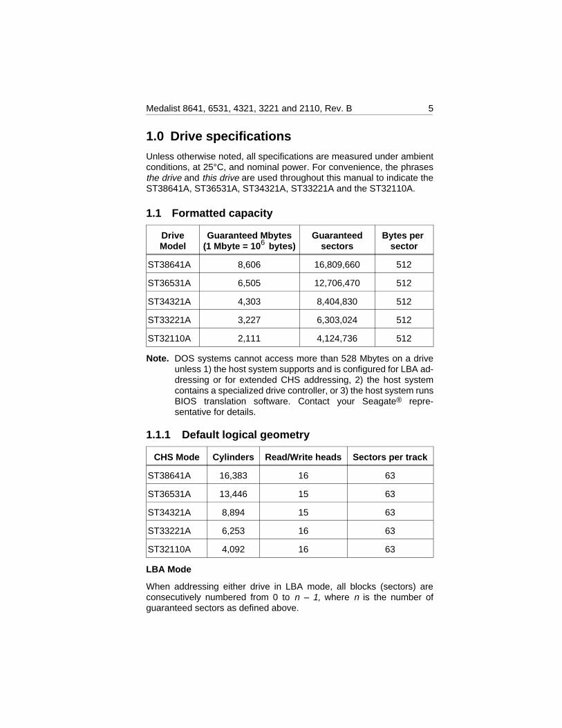
1.1 Formatted capacity
DriveModel
Guaranteed Mbytes(1 Mbyte = 10 6 bytes)
Guaranteedsectors
Bytes per sector
ST38641A 8,606 16,809,660 512
ST36531A 6,505 12,706,470 512
ST34321A 4,303 8,404,830 512
ST33221A 3,227 6,303,024 512
ST32110A 2,111 4,124,736 512
Note. DOS systems cannot access more than 528 Mbytes on a driveunless 1) the host system supports and is configured for LBA ad-dressing or for extended CHS addressing, 2) the host systemcontains a specialized drive controller, or 3) the host system runsBIOS translation software. Contact your Seagate® repre-sentative for details.
1.1.1 Default logical geometry
CHS Mode Cylinders Read/Write heads Sectors per track
ST38641A 16,383 16 63
ST36531A 13,446 15 63
ST34321A 8,894 15 63
ST33221A 6,253 16 63
ST32110A 4,092 16 63
LBA Mode
When addressing either drive in LBA mode, all blocks (sectors) areconsecutively numbered from 0 to n – 1, where n is the number ofguaranteed sectors as defined above.
Medalist 8641, 6531, 4321, 3221 and 2110, Rev. B 5
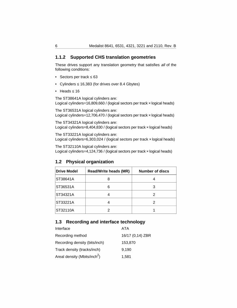
1.1.2 Supported CHS translation geometries
These drives support any translation geometry that satisfies all of thefollowing conditions:
• Sectors per track ≤ 63
• Cylinders ≤ 16,383 (for drives over 8.4 Gbytes)
• Heads ≤ 16
The ST38641A logical cylinders are:Logical cylinders=16,809,660 / (logical sectors per track × logical heads)
The ST36531A logical cylinders are:Logical cylinders=12,706,470 / (logical sectors per track × logical heads)
The ST34321A logical cylinders are:Logical cylinders=8,404,830 / (logical sectors per track × logical heads)
The ST33221A logical cylinders are:Logical cylinders=6,303,024 / (logical sectors per track × logical heads)
The ST32110A logical cylinders are:Logical cylinders=4,124,736 / (logical sectors per track × logical heads)
1.2 Physical organization
Drive Model Read/Write heads (MR) Number of discs
ST38641A 8 4
ST36531A 6 3
ST34321A 4 2
ST33221A 4 2
ST32110A 2 1
1.3 Recording and interface technologyInterface ATA
Recording method 16/17 (0,14) ZBR
Recording density (bits/inch) 153,870
Track density (tracks/inch) 9,190
Areal density (Mbits/inch2) 1,581
6 Medalist 8641, 6531, 4321, 3221 and 2110, Rev. B
Spindle speed RPM ( ± 0.2%) 5,400
Internal data-transfer rate(Mbits per second max)
140
I/O data-transfer rate(Mbytes per second max)
16.6 (PIO mode 4 with IORDY)16.6 (multiword DMA mode 2)33.3 (Ultra DMA mode 2)
Interleave 1:1
Cache buffer (Kbytes) 128
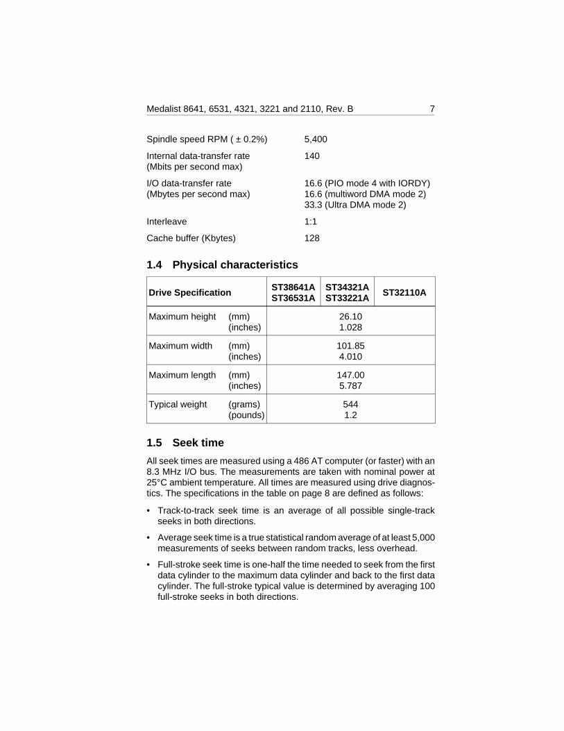
1.4 Physical characteristics
Drive Specification ST38641AST36531A
ST34321AST33221A ST32110A
Maximum height (mm)(inches)
26.101.028
Maximum width (mm)(inches)
101.854.010
Maximum length (mm)(inches)
147.005.787
Typical weight (grams)(pounds)
5441.2
1.5 Seek time
All seek times are measured using a 486 AT computer (or faster) with an8.3 MHz I/O bus. The measurements are taken with nominal power at25°C ambient temperature. All times are measured using drive diagnos-tics. The specifications in the table on page 8 are defined as follows:
• Track-to-track seek time is an average of all possible single-trackseeks in both directions.
• Average seek time is a true statistical random average of at least 5,000measurements of seeks between random tracks, less overhead.
• Full-stroke seek time is one-half the time needed to seek from the firstdata cylinder to the maximum data cylinder and back to the first datacylinder. The full-stroke typical value is determined by averaging 100full-stroke seeks in both directions.
Medalist 8641, 6531, 4321, 3221 and 2110, Rev. B 7
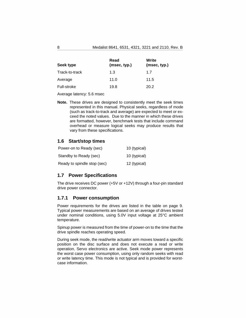
Seek typeRead(msec, typ.)
Write(msec, typ.)
Track-to-track 1.3 1.7
Average 11.0 11.5
Full-stroke 19.8 20.2
Average latency: 5.6 msec
Note. These drives are designed to consistently meet the seek timesrepresented in this manual. Physical seeks, regardless of mode(such as track-to-track and average) are expected to meet or ex-ceed the noted values. Due to the manner in which these drivesare formatted, however, benchmark tests that include commandoverhead or measure logical seeks may produce results thatvary from these specifications.
1.6 Start/stop timesPower-on to Ready (sec) 10 (typical)
Standby to Ready (sec) 10 (typical)
Ready to spindle stop (sec) 12 (typical)
1.7 Power Specifications
The drive receives DC power (+5V or +12V) through a four-pin standarddrive power connector.
1.7.1 Power consumption
Power requirements for the drives are listed in the table on page 9.Typical power measurements are based on an average of drives testedunder nominal conditions, using 5.0V input voltage at 25°C ambienttemperature.
Spinup power is measured from the time of power-on to the time that thedrive spindle reaches operating speed.
During seek mode, the read/write actuator arm moves toward a specificposition on the disc surface and does not execute a read or writeoperation. Servo electronics are active. Seek mode power representsthe worst case power consumption, using only random seeks with reador write latency time. This mode is not typical and is provided for worst-case information.
8 Medalist 8641, 6531, 4321, 3221 and 2110, Rev. B
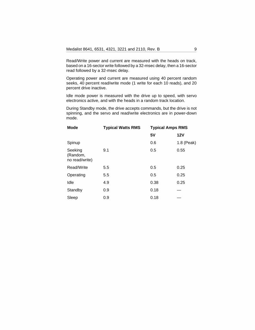
Read/Write power and current are measured with the heads on track,based on a 16-sector write followed by a 32-msec delay, then a 16-sectorread followed by a 32-msec delay.
Operating power and current are measured using 40 percent randomseeks, 40 percent read/write mode (1 write for each 10 reads), and 20percent drive inactive.
Idle mode power is measured with the drive up to speed, with servoelectronics active, and with the heads in a random track location.
During Standby mode, the drive accepts commands, but the drive is notspinning, and the servo and read/write electronics are in power-downmode.
Mode Typical Watts RMS Typical Amps RMS
5V 12V
Spinup 0.6 1.8 (Peak)
Seeking 9.1(Random,no read/write)
0.5 0.55
Read/Write 5.5 0.5 0.25
Operating 5.5 0.5 0.25
Idle 4.9 0.38 0.25
Standby 0.9 0.18 —
Sleep 0.9 0.18 —
Medalist 8641, 6531, 4321, 3221 and 2110, Rev. B 9
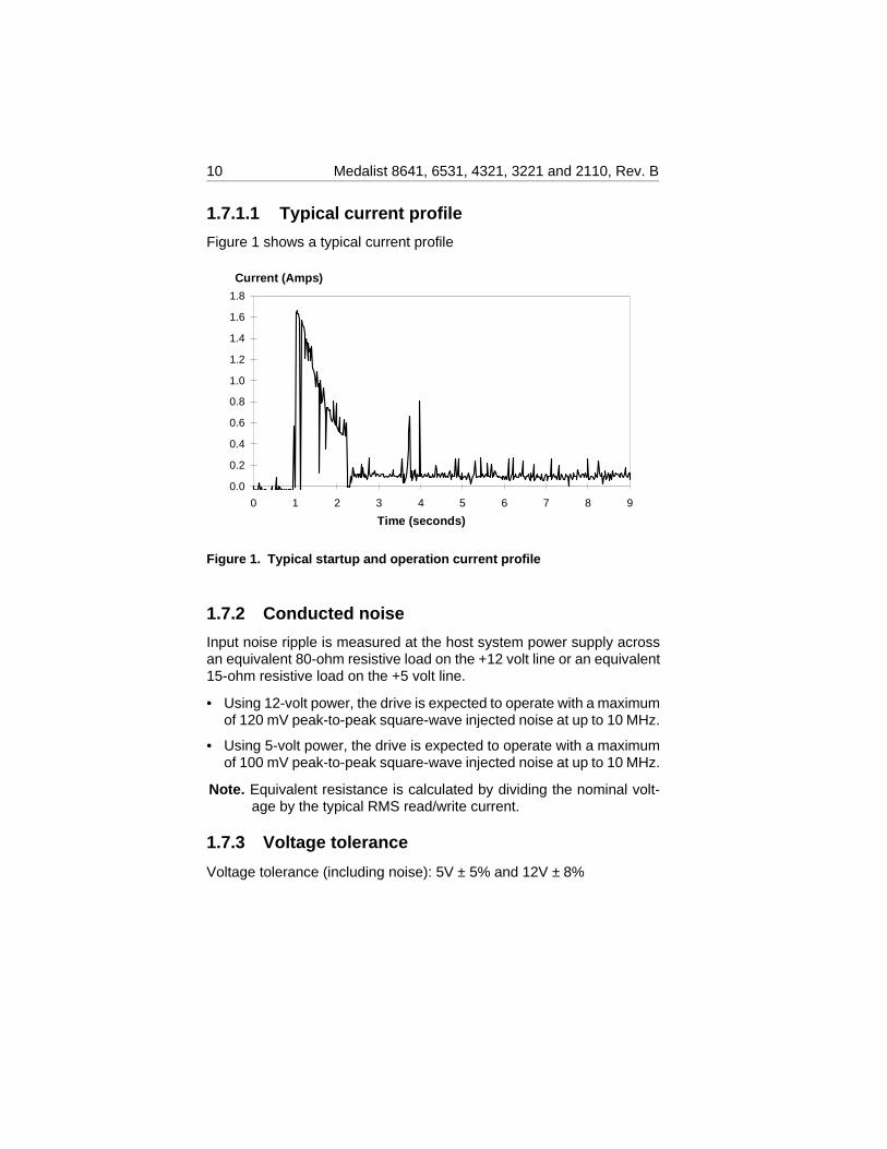
1.7.1.1 Typical current profile
Figure 1 shows a typical current profile
1.7.2 Conducted noise
Input noise ripple is measured at the host system power supply acrossan equivalent 80-ohm resistive load on the +12 volt line or an equivalent15-ohm resistive load on the +5 volt line.
• Using 12-volt power, the drive is expected to operate with a maximumof 120 mV peak-to-peak square-wave injected noise at up to 10 MHz.
• Using 5-volt power, the drive is expected to operate with a maximumof 100 mV peak-to-peak square-wave injected noise at up to 10 MHz.
Note. Equivalent resistance is calculated by dividing the nominal volt-age by the typical RMS read/write current.
1.7.3 Voltage tolerance
Voltage tolerance (including noise): 5V ± 5% and 12V ± 8%
0.0
0.2
0.4
0.6
0.8
1.0
1.2
1.4
1.6
1.8
0 1 2 3 4 5 6 7 8 9
Current (Amps)
Time (seconds)
Figure 1. Typical startup and operation current profile
10 Medalist 8641, 6531, 4321, 3221 and 2110, Rev. B
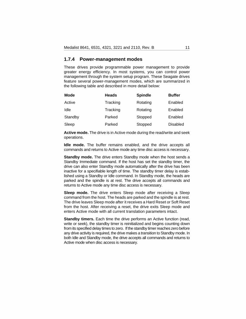
1.7.4 Power-management modes
These drives provide programmable power management to providegreater energy efficiency. In most systems, you can control powermanagement through the system setup program. These Seagate drivesfeature several power-management modes, which are summarized inthe following table and described in more detail below:
Mode Heads Spindle Buffer
Active Tracking Rotating Enabled
Idle Tracking Rotating Enabled
Standby Parked Stopped Enabled
Sleep Parked Stopped Disabled
Active mode. The drive is in Active mode during the read/write and seekoperations.
Idle mode. The buffer remains enabled, and the drive accepts allcommands and returns to Active mode any time disc access is necessary.
Standby mode. The drive enters Standby mode when the host sends aStandby Immediate command. If the host has set the standby timer, thedrive can also enter Standby mode automatically after the drive has beeninactive for a specifiable length of time. The standby timer delay is estab-lished using a Standby or Idle command. In Standby mode, the heads areparked and the spindle is at rest. The drive accepts all commands andreturns to Active mode any time disc access is necessary.
Sleep mode. The drive enters Sleep mode after receiving a Sleepcommand from the host. The heads are parked and the spindle is at rest.The drive leaves Sleep mode after it receives a Hard Reset or Soft Resetfrom the host. After receiving a reset, the drive exits Sleep mode andenters Active mode with all current translation parameters intact.
Standby timers. Each time the drive performs an Active function (read,write or seek), the standby timer is reinitialized and begins counting downfrom its specified delay times to zero. If the standby timer reaches zero beforeany drive activity is required, the drive makes a transition to Standby mode. Inboth Idle and Standby mode, the drive accepts all commands and returns toActive mode when disc access is necessary.
Medalist 8641, 6531, 4321, 3221 and 2110, Rev. B 11
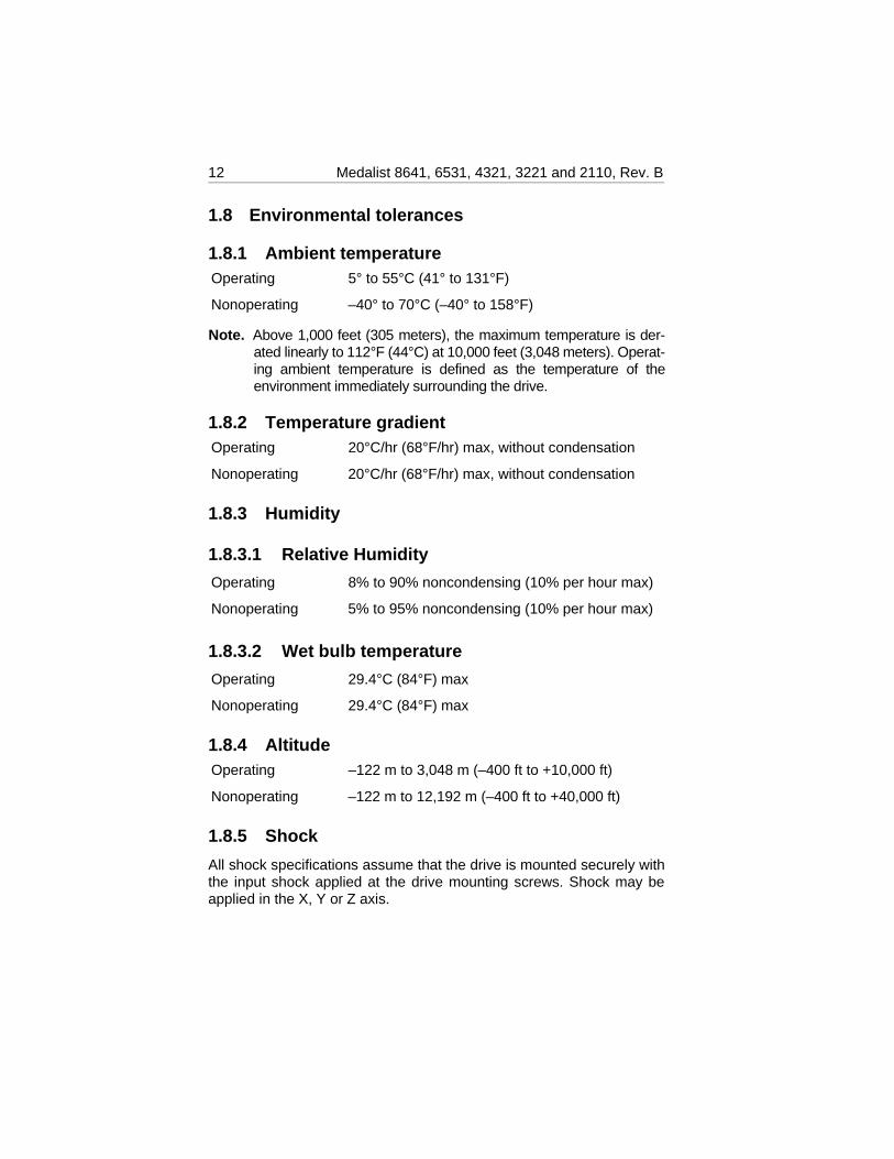
1.8 Environmental tolerances
1.8.1 Ambient temperatureOperating 5° to 55°C (41° to 131°F)
Nonoperating –40° to 70°C (–40° to 158°F)
Note. Above 1,000 feet (305 meters), the maximum temperature is der-ated linearly to 112°F (44°C) at 10,000 feet (3,048 meters). Operat-ing ambient temperature is defined as the temperature of theenvironment immediately surrounding the drive.
1.8.2 Temperature gradientOperating 20°C/hr (68°F/hr) max, without condensation
Nonoperating 20°C/hr (68°F/hr) max, without condensation
1.8.3 Humidity
1.8.3.1 Relative Humidity
Operating 8% to 90% noncondensing (10% per hour max)
Nonoperating 5% to 95% noncondensing (10% per hour max)
1.8.3.2 Wet bulb temperature
Operating 29.4°C (84°F) max
Nonoperating 29.4°C (84°F) max
1.8.4 AltitudeOperating –122 m to 3,048 m (–400 ft to +10,000 ft)
Nonoperating –122 m to 12,192 m (–400 ft to +40,000 ft)
1.8.5 Shock
All shock specifications assume that the drive is mounted securely withthe input shock applied at the drive mounting screws. Shock may beapplied in the X, Y or Z axis.
12 Medalist 8641, 6531, 4321, 3221 and 2110, Rev. B
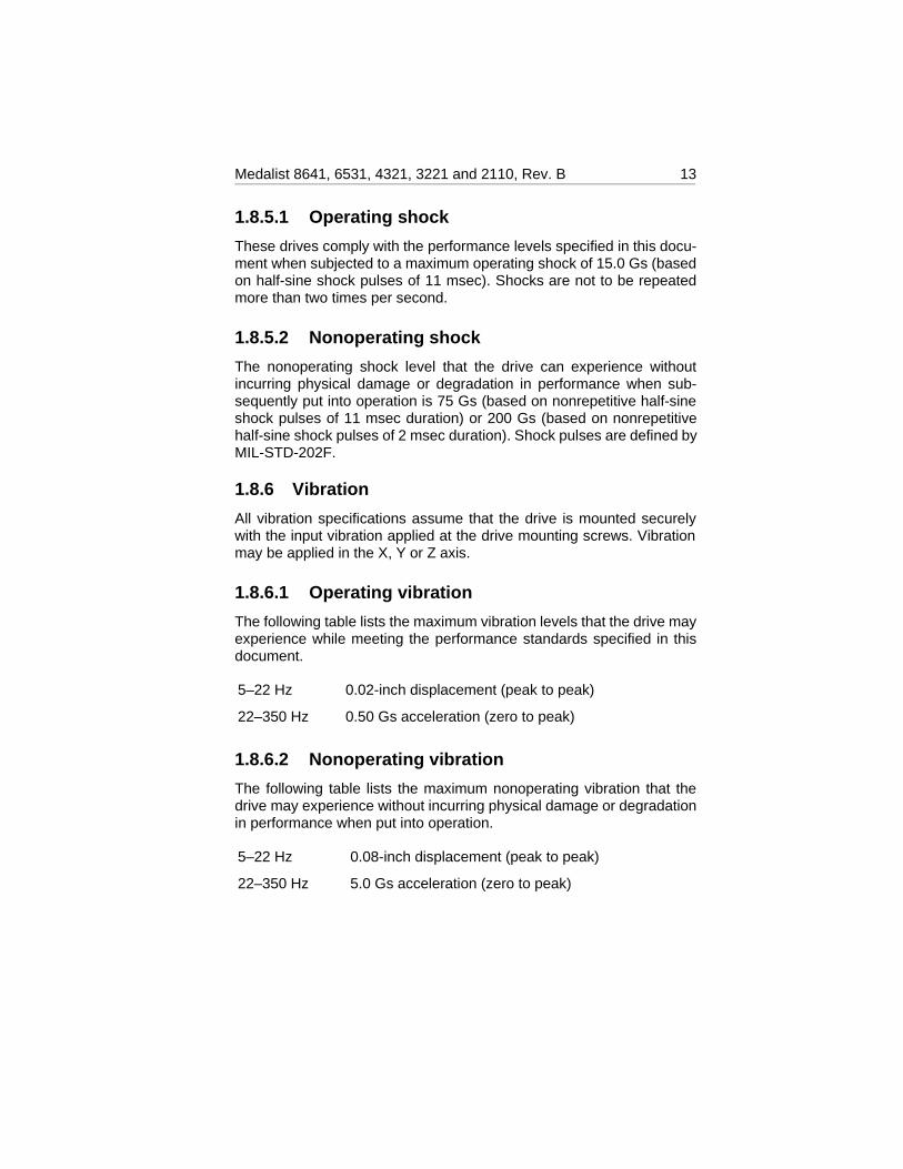
1.8.5.1 Operating shock
These drives comply with the performance levels specified in this docu-ment when subjected to a maximum operating shock of 15.0 Gs (basedon half-sine shock pulses of 11 msec). Shocks are not to be repeatedmore than two times per second.
1.8.5.2 Nonoperating shock
The nonoperating shock level that the drive can experience withoutincurring physical damage or degradation in performance when sub-sequently put into operation is 75 Gs (based on nonrepetitive half-sineshock pulses of 11 msec duration) or 200 Gs (based on nonrepetitivehalf-sine shock pulses of 2 msec duration). Shock pulses are defined byMIL-STD-202F.
1.8.6 Vibration
All vibration specifications assume that the drive is mounted securelywith the input vibration applied at the drive mounting screws. Vibrationmay be applied in the X, Y or Z axis.
1.8.6.1 Operating vibration
The following table lists the maximum vibration levels that the drive mayexperience while meeting the performance standards specified in thisdocument.
5–22 Hz 0.02-inch displacement (peak to peak)
22–350 Hz 0.50 Gs acceleration (zero to peak)
1.8.6.2 Nonoperating vibration
The following table lists the maximum nonoperating vibration that thedrive may experience without incurring physical damage or degradationin performance when put into operation.
5–22 Hz 0.08-inch displacement (peak to peak)
22–350 Hz 5.0 Gs acceleration (zero to peak)
Medalist 8641, 6531, 4321, 3221 and 2110, Rev. B 13
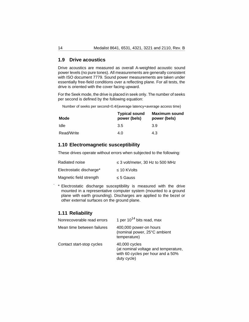
1.9 Drive acoustics
Drive acoustics are measured as overall A-weighted acoustic soundpower levels (no pure tones). All measurements are generally consistentwith ISO document 7779. Sound power measurements are taken underessentially free-field conditions over a reflecting plane. For all tests, thedrive is oriented with the cover facing upward.
For the Seek mode, the drive is placed in seek only. The number of seeksper second is defined by the following equation:
Number of seeks per second=0.4/(average latency+average access time)
ModeTypical soundpower (bels)
Maximum soundpower (bels)
Idle 3.5 3.9
Read/Write 4.0 4.3
1.10 Electromagnetic susceptibility
These drives operate without errors when subjected to the following:
Radiated noise ≤ 3 volt/meter, 30 Hz to 500 MHz
Electrostatic discharge* ≤ 10 KVolts
Magnetic field strength ≤ 5 Gauss
* Electrostatic discharge susceptibility is measured with the drivemounted in a representative computer system (mounted to a groundplane with earth grounding). Discharges are applied to the bezel orother external surfaces on the ground plane.
1.11 ReliabilityNonrecoverable read errors 1 per 1014 bits read, max
Mean time between failures 400,000 power-on hours (nominal power, 25°C ambienttemperature)
Contact start-stop cycles 40,000 cycles(at nominal voltage and temperature,with 60 cycles per hour and a 50%duty cycle)
14 Medalist 8641, 6531, 4321, 3221 and 2110, Rev. B
1.12 Agency certification
1.12.1 Safety certification
The drives are recognized in accordance with UL 1950 and CSA C22.2(950) and meet all applicable sections of IEC950 and EN 60950 as testedby TUV North America.
1.12.2 Electromagnetic Compatibility
Hard drives that display the CE marking comply with European Unionrequirements specified in Electromagnetic Compatibility Directives. Test-ing is performed to standards EN50082-1 and EN55022-B.
Seagate uses an independent laboratory to confirm compliance with theEC directives specified in the previous paragraph. Drives are tested inrepresentative end-user systems. Although CE-marked Seagate drivescomply with the directives when used in the test systems, we cannotguarantee that all systems will comply with the directives. The drive isdesigned for operation inside a properly designed enclosure, with prop-erly shielded I/O cable (if necessary) and terminators on all unused I/Oports. Computer manufacturers and system integrators should confirmEMC compliance and provide CE marking for their products.
Australian C-Tick
If this model has the C-Tick marking, it complies with the Australia/NewZealand Standard AS/NZS3548 1995 and meets the ElectromagneticCompatibility (EMC) Framework requirements of Australia’s SpectrumManagement Agency (SMA).
1.12.3 FCC verification
These drives are intended to be contained solely within a personalcomputer or similar enclosure (not attached as an external device). Assuch, each drive is considered to be a subassembly even when it isindividually marketed to the customer. As a subassembly, no FederalCommunications Commission verification or certification of the device isrequired.
Seagate Technology, Inc. has tested this device in enclosures as de-scribed above to ensure that the total assembly (enclosure, disc drive,motherboard, power supply, etc.) does comply with the limits for a ClassB computing device, pursuant to Subpart J, Part 15 of the FCC rules.Operation with noncertified assemblies is likely to result in interferenceto radio and television reception.
Medalist 8641, 6531, 4321, 3221 and 2110, Rev. B 15
Radio and Television Interference. This equipment generates and usesradio frequency energy and if not installed and used in strict accordancewith the manufacturer’s instructions, may cause interference to radio andtelevision reception.
This equipment is designed to provide reasonable protection againstsuch interference in a residential installation. However, there is noguarantee that interference will not occur in a particular installation. If thisequipment does cause interference to radio or television, which can bedetermined by turning the equipment on and off, you are encouraged totry one or more of the following corrective measures:
• Reorient the receiving antenna.
• Move the device to one side or the other of the radio or TV.
• Move the device farther away from the radio or TV.
• Plug the computer into a different outlet so that the receiver andcomputer are on different branch outlets.
If necessary, you should consult your dealer or an experienced radio/tele-vision technician for additional suggestions. You may find helpful thefollowing booklet prepared by the Federal Communications Commission:How to Identify and Resolve Radio-Television Interference Problems.This booklet is available from the Superintendent of Documents,U.S. Government Printing Office, Washington, DC 20402. Refer to pub-lication number 004-000-00345-4.
16 Medalist 8641, 6531, 4321, 3221 and 2110, Rev. B
2.0 Drive mounting and configuration
2.1 Handling and static-discharge precautions
After unpacking, and before installation, the drive may be exposed topotential handling and electrostatic discharge (ESD) hazards. Observestandard static-discharge precautions. A grounded wrist-strap is preferred.
Handle the drive only by the sides of the head/disc assembly. Avoidcontact with the printed circuit board, all electronic components and theinterface connector. Do not apply pressure to the top cover of the drive.Always rest the drive on a padded antistatic surface until you mount it inthe host system.
2.2 Jumper settings
2.2.1 Master/slave configuration
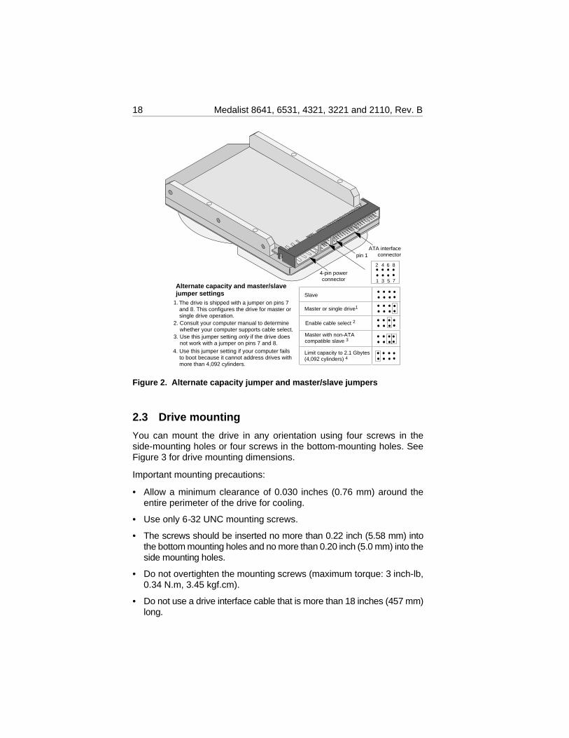
You must establish a master/slave relationship between two drives thatare attached to a single AT bus. You can configure a drive to be a masteror slave by setting the master/slave jumpers, shown in Figure 2 onpage 18.
These drives support master/slave configuration using the cable selectoption. This requires a special daisy-chain cable that grounds pin 28(CSEL) on one of its two drive connectors. If you attach the drive to thegrounded CSEL connector, it becomes a master. If you attach the driveto the ungrounded CSEL connector, it becomes a slave. To use thisoption, the host system and both drives must support cable select, andboth drives must be configured for cable select. To configure this drivefor cable select, install a jumper as shown in Figure 2.
For the master drive to recognize the slave drive using the DASP– signal,the slave drive must assert the DASP– signal at power up, and the masterdrive must monitor DASP– at power up.
2.2.2 Alternate capacity jumper
Some older computers may “hang” if their BIOS detects a hard drive thathas more than 4,092 cylinders at startup. To allow these computers torecognize the ST38641A, the ST36531A, the ST34321 or the ST33221A,these drives include a capacity-limiting jumper, which sets the drive’sdefault translation geometry to 4,092 cylinders. This limits the drive’scapacity to 2.1 Gbytes, unless third-party software is used.
Medalist 8641, 6531, 4321, 3221 and 2110, Rev. B 17
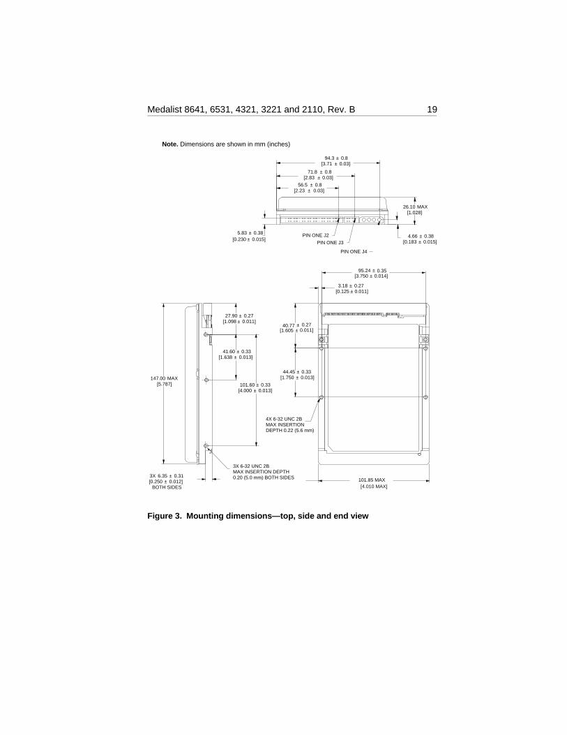
2.3 Drive mounting
You can mount the drive in any orientation using four screws in theside-mounting holes or four screws in the bottom-mounting holes. SeeFigure 3 for drive mounting dimensions.
Important mounting precautions:
• Allow a minimum clearance of 0.030 inches (0.76 mm) around theentire perimeter of the drive for cooling.
• Use only 6-32 UNC mounting screws.
• The screws should be inserted no more than 0.22 inch (5.58 mm) intothe bottom mounting holes and no more than 0.20 inch (5.0 mm) into theside mounting holes.
• Do not overtighten the mounting screws (maximum torque: 3 inch-lb,0.34 N.m, 3.45 kgf.cm).
• Do not use a drive interface cable that is more than 18 inches (457 mm)long.
pin 1ATA interface
connector
Alternate capacity and master/slave jumper settings
3. Use this jumper setting only if the drive does not work with a jumper on pins 7 and 8.
The drive is shipped with a jumper on pins 7 and 8. This configures the drive for master or single drive operation.
1.
2. Consult your computer manual to determine whether your computer supports cable select.
1 3 5
2 4 6
7
8
Limit capacity to 2.1 Gbytes(4,092 cylinders) 4
Slave
Master or single drive1
Master with non-ATAcompatible slave 3
Enable cable select 2
4-pin powerconnector
4. Use this jumper setting if your computer fails to boot because it cannot address drives with more than 4,092 cylinders.
Figure 2. Alternate capacity jumper and master/slave jumpers
18 Medalist 8641, 6531, 4321, 3221 and 2110, Rev. B
BOTH SIDES
[5.787]147.00 MAX
[1.098 ± 0.011]27.90 ± 0.27
[1.638 ± 0.013]41.60 ± 0.33
[4.000 ± 0.013]101.60 ± 0.33
[1.750 ± 0.013]44.45 ± 0.33
[1.605 ± 0.011]40.77 ± 0.27
[0.125 ± 0.011]3.18 ± 0.27
[3.750 ± 0.014]95.24 ± 0.35
3X 6-32 UNC 2BMAX INSERTION DEPTH0.20 (5.0 mm) BOTH SIDES
[0.250 ± 0.012]3X 6.35 ± 0.31
[4.010 MAX]101.85 MAX
4X 6-32 UNC 2BMAX INSERTIONDEPTH 0.22 (5.6 mm)
Note. Dimensions are shown in mm (inches)
[1.028]26.10 MAX
PIN ONE J4
PIN ONE J3
PIN ONE J2[0.230 ± 0.015]
5.83 ± 0.38
[0.183 ± 0.015]4.66 ± 0.38
[3.71 ± 0.03]94.3 ± 0.8
[2.83 ± 0.03]71.8 ± 0.8
[2.23 ± 0.03]56.5 ± 0.8
Figure 3. Mounting dimensions—top, side and end view
Medalist 8641, 6531, 4321, 3221 and 2110, Rev. B 19

20 Medalist 8641, 6531, 4321, 3221 and 2110, Rev. B
3.0 ATA interface These drives use the industry-standard ATA task file interface thatsupports 16-bit data transfers. It supports ATA programmed input/output(PIO) modes 0, 1, 2, 3 and 4; multiword DMA modes 0, 1 and 2; and UltraDMA modes 0, 1 and 2. The drive also supports the use of the IORDYsignal to provide reliable high-speed data transfers.
You can use a daisy-chain cable to connect two drives to a single AThost bus. For detailed information regarding the ATA interface, refer tothe draft of AT Attachment with Packet Interface Extension (ATA/ATAPI-4), NCITS T13 1153D, subsequently referred to as the Draft ATA-4Standard.
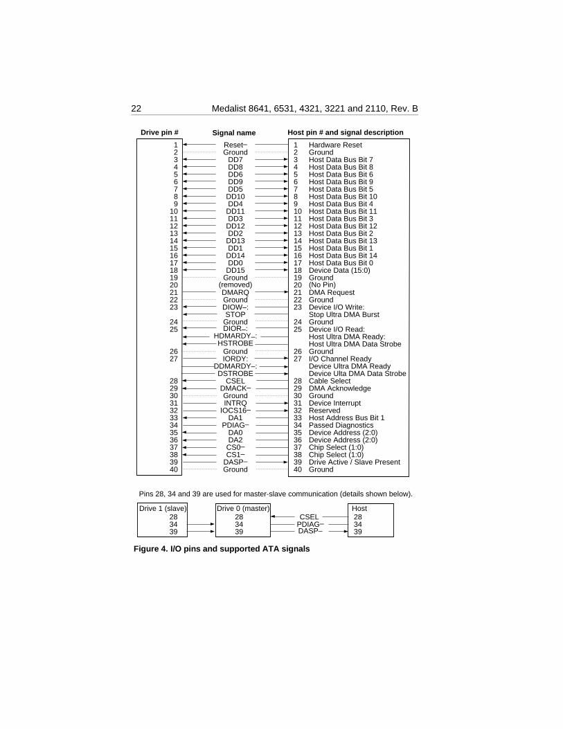
3.1 ATA interface signals and connector pins
Figure 4 on page 22 summarizes the signals on the ATA interfaceconnector that the drive supports. For a detailed description of thesesignals, refer to the Draft ATA-4 Standard.
Medalist 8641, 6531, 4321, 3221 and 2110, Rev. B 21
Reset–Ground
DD7DD8DD6DD9DD5
DD10DD4
DD11DD3
DD12DD2
DD13DD1
DD14DD0
DD15Ground
(removed)DMARQGroundDIOW–:STOP
GroundDIOR–:
HDMARDY–:HSTROBE
GroundIORDY:
DDMARDY–:DSTROBE
CSELDMACK–GroundINTRQ
IOCS16–DA1
PDIAG–DA0DA2
CS0–CS1–
DASP–Ground
1234567891011121314151617181920212223
2425
2627
28293031323334353637383940
Hardware ResetGroundHost Data Bus Bit 7Host Data Bus Bit 8Host Data Bus Bit 6Host Data Bus Bit 9Host Data Bus Bit 5Host Data Bus Bit 10Host Data Bus Bit 4Host Data Bus Bit 11Host Data Bus Bit 3Host Data Bus Bit 12Host Data Bus Bit 2Host Data Bus Bit 13Host Data Bus Bit 1Host Data Bus Bit 14Host Data Bus Bit 0Device Data (15:0)Ground(No Pin)DMA RequestGroundDevice I/O Write:Stop Ultra DMA Burst GroundDevice I/O Read:Host Ultra DMA Ready:Host Ultra DMA Data StrobeGroundI/O Channel ReadyDevice Ultra DMA ReadyDevice Ulta DMA Data StrobeCable Select DMA AcknowledgeGroundDevice InterruptReservedHost Address Bus Bit 1Passed DiagnosticsDevice Address (2:0)Device Address (2:0)Chip Select (1:0)Chip Select (1:0)Drive Active / Slave PresentGround
Host pin # and signal description
123456789
1011121314151617181920212223
2425
2627
28293031323334353637383940
Drive pin # Signal name
Pins 28, 34 and 39 are used for master-slave communication (details shown below).
Host283439
Drive 0 (master)Drive 1 (slave)283439
283439
CSEL PDIAG–DASP–
Figure 4. I/O pins and supported ATA signals
22 Medalist 8641, 6531, 4321, 3221 and 2110, Rev. B
3.2 ATA Interface commands
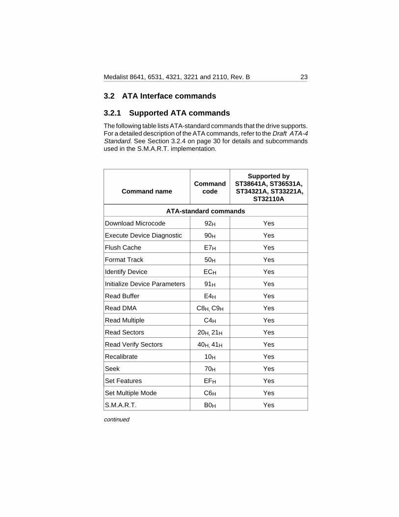
3.2.1 Supported ATA commands
The following table lists ATA-standard commands that the drive supports.For a detailed description of the ATA commands, refer to the Draft ATA-4Standard. See Section 3.2.4 on page 30 for details and subcommandsused in the S.M.A.R.T. implementation.
Command nameCommand
code
Supported byST38641A, ST36531A, ST34321A, ST33221A,
ST32110A
ATA-standard commands
Download Microcode 92H Yes
Execute Device Diagnostic 90H Yes
Flush Cache E7H Yes
Format Track 50H Yes
Identify Device ECH Yes
Initialize Device Parameters 91H Yes
Read Buffer E4H Yes
Read DMA C8H, C9H Yes
Read Multiple C4H Yes
Read Sectors 20H, 21H Yes
Read Verify Sectors 40H, 41H Yes
Recalibrate 10H Yes
Seek 70H Yes
Set Features EFH Yes
Set Multiple Mode C6H Yes
S.M.A.R.T. B0H Yes
continued
Medalist 8641, 6531, 4321, 3221 and 2110, Rev. B 23
Command nameCommand
code
Supported byST38641A, ST36531A, ST34321A, ST33221A,
ST32110A
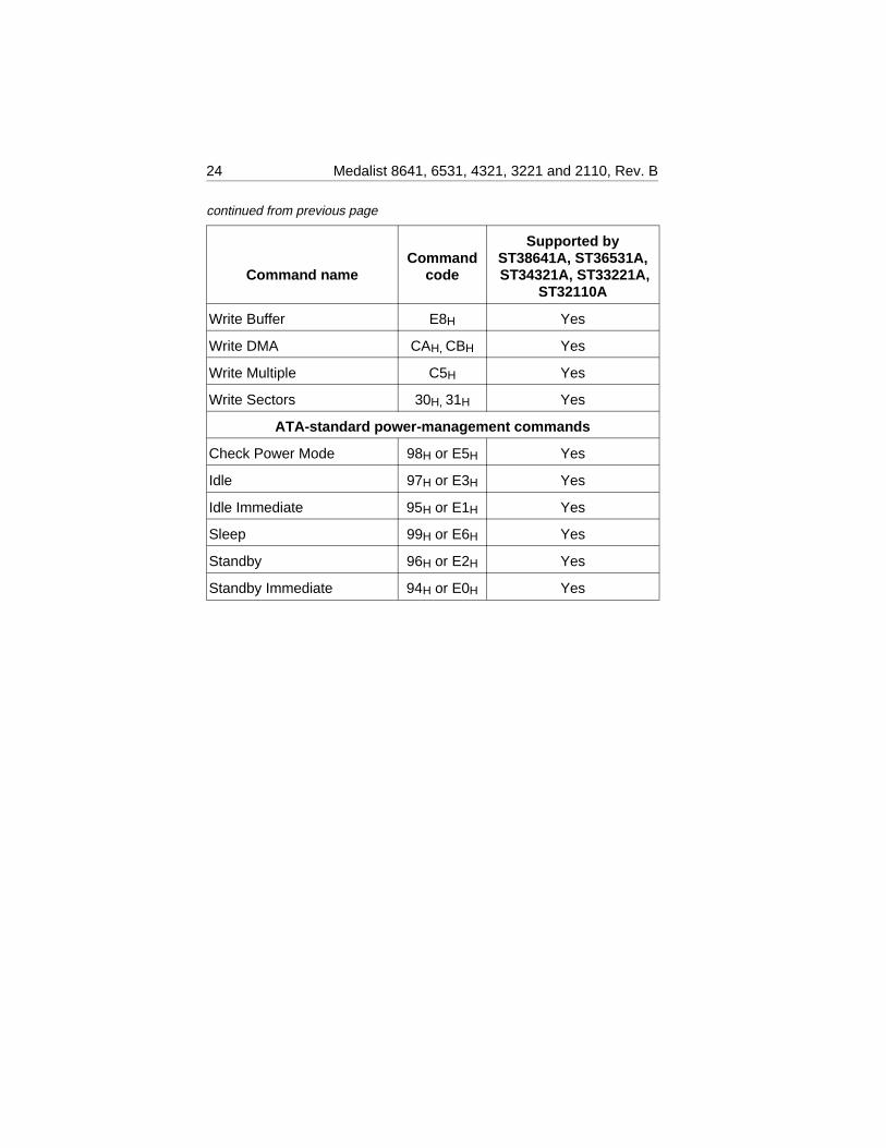
Write Buffer E8H Yes
Write DMA CAH, CBH Yes
Write Multiple C5H Yes
Write Sectors 30H, 31H Yes
ATA-standard power-management commands
Check Power Mode 98H or E5H Yes
Idle 97H or E3H Yes
Idle Immediate 95H or E1H Yes
Sleep 99H or E6H Yes
Standby 96H or E2H Yes
Standby Immediate 94H or E0H Yes
continued from previous page
24 Medalist 8641, 6531, 4321, 3221 and 2110, Rev. B
The following commands contain drive-specific features that may not bedescribed in the Draft ATA-4 Standard.
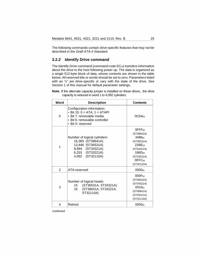
3.2.2 Identify Drive command
The Identify Drive command (command code ECH) transfers informationabout the drive to the host following power up. The data is organized asa single 512-byte block of data, whose contents are shown in the tablebelow. All reserved bits or words should be set to zero. Parameters listedwith an “x” are drive-specific or vary with the state of the drive. SeeSection 1 of this manual for default parameter settings.
Note. If the alternate capacity jumper is installed on these drives, the drivecapacity is reduced in word 1 to 4,092 cylinders.
Word Description Contents
0
Configuration information:• Bit 15: 0 = ATA; 1 = ATAPI• Bit 7: removable media• Bit 6: removable controller• Bit 0: reserved
0C5AH
1
Number of logical cylinders:16,383 (ST38641A)13,446 (ST36531A)8,894 (ST34321A)6,253 (ST33221A)4,092 (ST32110A)
3FFFH(ST38641A)
3486H(ST36531A)
22BEH(ST34321A)
186DH(ST33221A)
0FFCH(ST32110A)
2 ATA-reserved 0000H
3
Number of logical heads:15 (ST36531A, ST34321A)16 (ST38641A, ST33221A,
ST32110A)
000FH(ST36531A)
(ST34321A)
0010H(ST38641A)
(ST33221A)
(ST32110A)
4 Retired 0000H
continued
Medalist 8641, 6531, 4321, 3221 and 2110, Rev. B 25
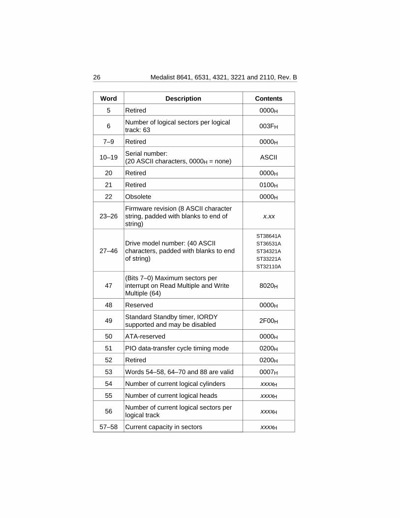
Word Description Contents
5 Retired 0000H
6Number of logical sectors per logicaltrack: 63
003FH
7–9 Retired 0000H
10–19Serial number:(20 ASCII characters, 0000H = none)
ASCII
20 Retired 0000H
21 Retired 0100H
22 Obsolete 0000H
23–26Firmware revision (8 ASCII characterstring, padded with blanks to end ofstring)
x.xx
27–46Drive model number: (40 ASCIIcharacters, padded with blanks to endof string)
ST38641A
ST36531A
ST34321A
ST33221A
ST32110A
47(Bits 7–0) Maximum sectors perinterrupt on Read Multiple and WriteMultiple (64)
8020H
48 Reserved 0000H
49Standard Standby timer, IORDYsupported and may be disabled
2F00H
50 ATA-reserved 0000H
51 PIO data-transfer cycle timing mode 0200H
52 Retired 0200H
53 Words 54–58, 64–70 and 88 are valid 0007H
54 Number of current logical cylinders xxxxH
55 Number of current logical heads xxxxH
56Number of current logical sectors perlogical track xxxxH
57–58 Current capacity in sectors xxxxH
26 Medalist 8641, 6531, 4321, 3221 and 2110, Rev. B
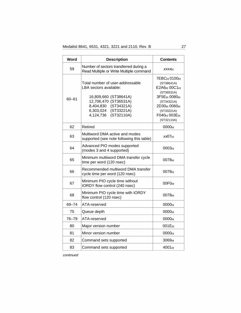
Word Description Contents
59Number of sectors transferred during aRead Multiple or Write Multiple command xxxxH
60–61
Total number of user-addressableLBA sectors available:
16,809,660 (ST38641A)12,706,470 (ST36531A)8,404,830 (ST34321A)6,303,024 (ST33221A)4,124,736 (ST32110A)
7EBCH 0100H(ST38641A)
E2A6H 00C1H(ST36531A)
3F5EH 0080H(ST34321A)
2D30H 0060H(ST33221A)
F040H 003EH(ST32110A)
62 Retired 0000H
63Multiword DMA active and modessupported (see note following this table)
xx07H
64Advanced PIO modes supported(modes 3 and 4 supported)
0003H
65Minimum multiword DMA transfer cycletime per word (120 nsec)
0078H
66Recommended multiword DMA transfercycle time per word (120 nsec)
0078H
67Minimum PIO cycle time withoutIORDY flow control (240 nsec)
00F0H
68Minimum PIO cycle time with IORDYflow control (120 nsec)
0078H
69–74 ATA-reserved 0000H
75 Queue depth 0000H
76–79 ATA-reserved 0000H
80 Major version number 001EH
81 Minor version number 0000H
82 Command sets supported 3069H
83 Command sets supported 4001H
continued
Medalist 8641, 6531, 4321, 3221 and 2110, Rev. B 27
Word Description Contents
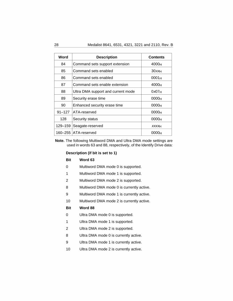
84 Command sets support extension 4000H
85 Command sets enabled 30xxH
86 Command sets enabled 0001H
87 Command sets enable extension 4000H
88 Ultra DMA support and current mode 0x07H
89 Security erase time 0000H
90 Enhanced security erase time 0000H
91–127 ATA-reserved 0000H
128 Security status 0000H
129–159 Seagate-reserved xxxxH
160–255 ATA-reserved 0000H
Note. The following Multiword DMA and Ultra DMA mode settings areused in words 63 and 88, respectively, of the Identify Drive data:
Description (if bit is set to 1)
Bit Word 63
0 Multiword DMA mode 0 is supported.
1 Multiword DMA mode 1 is supported.
2 Multiword DMA mode 2 is supported.
8 Multiword DMA mode 0 is currently active.
9 Multiword DMA mode 1 is currently active.
10 Multiword DMA mode 2 is currently active.
Bit Word 88
0 Ultra DMA mode 0 is supported.
1 Ultra DMA mode 1 is supported.
2 Ultra DMA mode 2 is supported.
8 Ultra DMA mode 0 is currently active.
9 Ultra DMA mode 1 is currently active.
10 Ultra DMA mode 2 is currently active.
28 Medalist 8641, 6531, 4321, 3221 and 2110, Rev. B
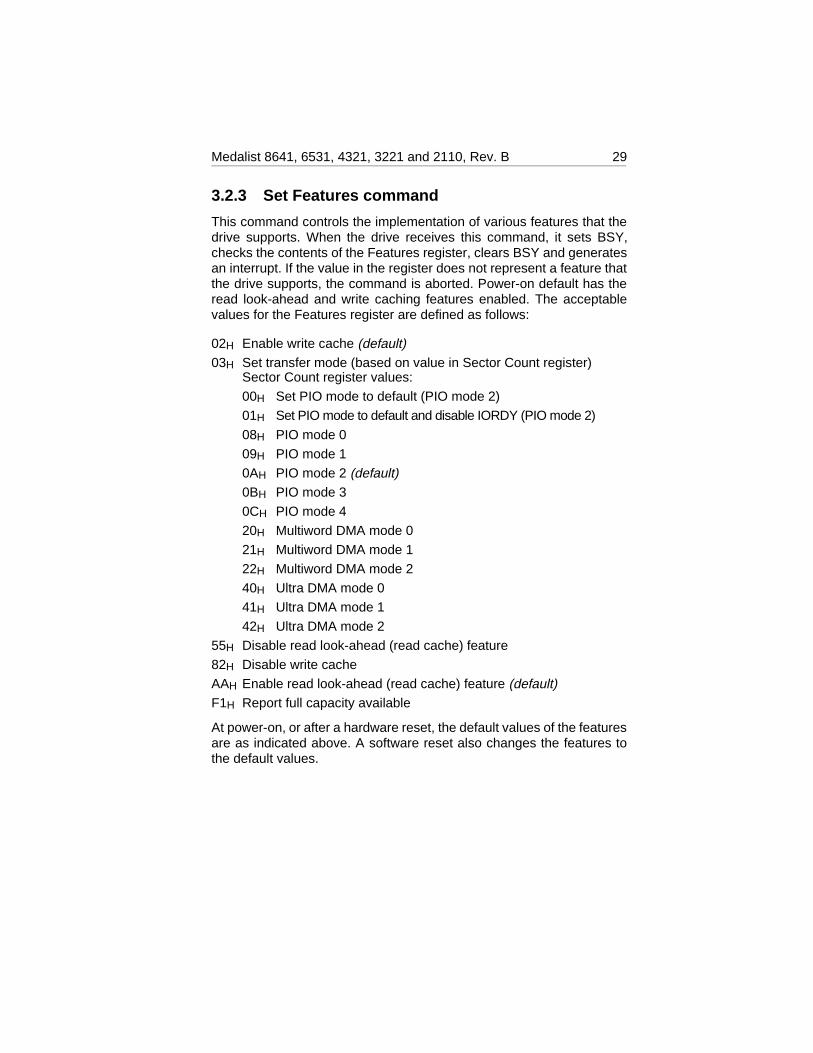
3.2.3 Set Features command
This command controls the implementation of various features that thedrive supports. When the drive receives this command, it sets BSY,checks the contents of the Features register, clears BSY and generatesan interrupt. If the value in the register does not represent a feature thatthe drive supports, the command is aborted. Power-on default has theread look-ahead and write caching features enabled. The acceptablevalues for the Features register are defined as follows:
02H Enable write cache (default)03H Set transfer mode (based on value in Sector Count register)
Sector Count register values:
00H Set PIO mode to default (PIO mode 2)
01H Set PIO mode to default and disable IORDY (PIO mode 2)
08H PIO mode 0
09H PIO mode 1
0AH PIO mode 2 (default)0BH PIO mode 3
0CH PIO mode 4
20H Multiword DMA mode 0
21H Multiword DMA mode 1
22H Multiword DMA mode 2
40H Ultra DMA mode 0
41H Ultra DMA mode 1
42H Ultra DMA mode 2
55H Disable read look-ahead (read cache) feature
82H Disable write cache
AAH Enable read look-ahead (read cache) feature (default)F1H Report full capacity available
At power-on, or after a hardware reset, the default values of the featuresare as indicated above. A software reset also changes the features tothe default values.
Medalist 8641, 6531, 4321, 3221 and 2110, Rev. B 29
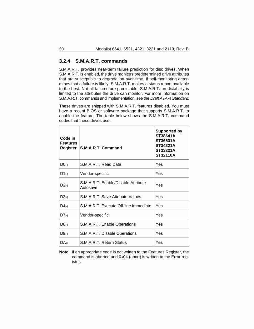
3.2.4 S.M.A.R.T. commands
S.M.A.R.T. provides near-term failure prediction for disc drives. WhenS.M.A.R.T. is enabled, the drive monitors predetermined drive attributesthat are susceptible to degradation over time. If self-monitoring deter-mines that a failure is likely, S.M.A.R.T. makes a status report availableto the host. Not all failures are predictable. S.M.A.R.T. predictability islimited to the attributes the drive can monitor. For more information onS.M.A.R.T. commands and implementation, see the Draft ATA-4 Standard.
These drives are shipped with S.M.A.R.T. features disabled. You musthave a recent BIOS or software package that supports S.M.A.R.T. toenable the feature. The table below shows the S.M.A.R.T. commandcodes that these drives use.
Code inFeaturesRegister S.M.A.R.T. Command
Supported byST38641AST36531AST34321AST33221AST32110A
D0H S.M.A.R.T. Read Data Yes
D1H Vendor-specific Yes
D2HS.M.A.R.T. Enable/Disable AttributeAutosave
Yes
D3H S.M.A.R.T. Save Attribute Values Yes
D4H S.M.A.R.T. Execute Off-line Immediate Yes
D7H Vendor-specific Yes
D8H S.M.A.R.T. Enable Operations Yes
D9H S.M.A.R.T. Disable Operations Yes
DAH S.M.A.R.T. Return Status Yes
Note. If an appropriate code is not written to the Features Register, thecommand is aborted and 0x04 (abort) is written to the Error reg-ister.
30 Medalist 8641, 6531, 4321, 3221 and 2110, Rev. B

Seagate Technology, Inc.920 Disc Drive, Scotts Valley, California 95066, USA
Publication Number: 20400075-001, Rev. B, Printed in USA