Embed Size (px)
Citation preview

DISTRIBUTION STATEMENT A: Approved for public release; distribution is unlimited.
NONRESIDENT
TRAINING COURSE
October 1992
Gas Turbine Systems Technician (Electrical) 2 NAVEDTRA 14112

DISTRIBUTION STATEMENT A: Approved for public release; distribution is unlimited.
Although the words “he,” “him,” and “his” are used sparingly in this course to enhance communication, they are not intended to be gender driven or to affront or discriminate against anyone.

COMMANDING OFFICERNETPDTC
6490 SAUFLEY FIELD RDPENSACOLA, FL 32509-5237
ERRATA #110 Aug 1999
Specific Instructions and Errata forTraining Manual
GAS TURBINE SYSTEMS TECHNICIAN (ELECTRICAL)
1. No attempt has been made to issue corrections for errors in typing,punctuation, etc.
2. Whenever the following manuals are referenced, make the indicated changesin the training manual:
a. Change Tools and Their Uses, NAVEDTRA 10085, to Use and Care of HandTools and Measuring Tools, NAVEDTRA 12085.
b. Change NAVPERS 10868E (change 2), to NAVPERS 18068 (VOLUME 1).Change Blueprint Reading and Sketching, NAVEDTRA 10077, to BlueprintReading and Sketching, NAVEDTRA 12014.
C. Change Electrician's Mate 3&2, NAVEDTRA 10546-F, to Electrician'sMate, NAVEDTRA 12164.
3. Change the following items in the training manual:
a.b.C.
d.
e.
f.
h.
Page iii, delete "and PHM" from title of chapter 5.Throughout the manual, delete all references to DDG-993.Pages 1-5 through 1-7, Figures 1-1, 1-2, and 1-3, add "Note: See NSTMChapter 220, Volume 2, Section 27, for updated sample entries utilizingthese forms."Page 2-2, under the heading "FFG-7 CLASS SHIPS" in the secondparagraph, change "20 6-volt lead-acid storage batteries" to "10 12-volt maintenance free batteries..."Page 5-39, under the heading "WATER WASH SYSTEM" in the secondparagraph, delete "and PHM-" from the first sentence and delete theentire last sentence in same paragraph.Page 7-1, change chapter title to read "LCAC PROPULSION SYSTEMS."Delete "and patrol combatant missile (hydrofoil) (PHM) class ships"from the first sentence in the first paragraph. Delete "or a PHM" fromthe second sentence in the first paragraph. Delete references to PHM inthe second and third paragraphs.Pages 7-19 through 7-40, delete the entire Patrol Combatant Missile(Hydrofoil) section, in the right column starting with "NOW, let's lookat the propulsion system of another type of landing craft, the patrolcombatant missile (hydrofoil) or PHM." through page 7-40, includingassociated figures 7-18 through 7-36.Pages 7-40 and 7-41, change the entire "SUMMARY" to the following:
‘This chapter has provided you with a variety of information tohelp you become familiar with the propulsion systems and electricalsystems on the LCAC class ships.

In this chapter, we discussed several of the control systems,design and basic maintenance. We also discussed the vessel'selectrical system and the APU. We briefly described the LCAC'smaintenance system and the troubleshooting techniques used inisolating and repairing equipment malfunctions.
As a GSE, you may find yourself assigned to this class of ship.This chapter should have provided you with a basic understanding ofthe engineering systems found on the LCAC class ships."
4. Change the following items in the appendices of the training manual:
a.
b.
C.
d.
e.f.
g.
h.
Page AI-1, delete "AUTOMATIC CONTROL SYSTEM" and "BULKHEAD-MOUNTEDELECTRONICS ENCLOSURE (BMEE)" and associated definitions.Page AI-3, delete ‘ENGINEER OPERATING STATION (EOS)" and associateddefinition.Page AI-7, delete "SHIP'S SERVICE POWER UNIT (SSPU)" and associateddefinition.Page AI-8, under the heading ‘WASTE HEAT BOILER (WHB)," delete "DDG-51."Page AII-1, delete "ACS" and "BMEE."Page AII-4, delete "PHM."Page AII-5, delete "SSPU."Page AV-1, add "Module 23 Magnetic Recording" and "Module 24Introduction to Fiber Optics."Pages AVI-5 and AVI-6, under the heading "Chapter 7," delete sixreferences starting with Mobile Electric Power Plant.

COMMANDING OFFICERNETPDTC
6490 SAUFLEY FIELD RDPENSACOLA, FL 32509-5237
10 Aug 1999
ERRATA #1
Specific Instructions and Errata forNonresident Training Course
GAS TURBINE SYSTEMS TECHNICIAN (ELECTRICAL)
1. No attempt has been made to issue corrections for errors in typing,punctuation, etc., that do not affect your ability to answer the question orquestions.
2. To receive credit for deleted questions, show this errata to your localcourse administrator (ESO/scorer). The local course administrator is directedto correct the course and the answer key by indicating the questions deleted.
3. Assignment Booklet
Delete the following questions, and leave the corresponding spaces blank onthe answer sheets:
Questions
4-32 through 4-75
Make the following changes:
Questions Change
1-55 In response #2, change "(a) 20" to "(a) 10"2-24 In response #4, change "distribution" to "distributor"


i
PREFACE By enrolling in this self-study course, you have demonstrated a desire to improve yourself and the Navy. Remember, however, this self-study course is only one part of the total Navy training program. Practical experience, schools, selected reading, and your desire to succeed are also necessary to successfully round out a fully meaningful training program. COURSE OVERVIEW: In completing this nonresident training course, you will demonstrate a knowledge of the subject matter by correctly answering questions on the following: engineering administration; uninterrupted power supply systems; engineering control system operations; engineering support systems maintenance; electrical and electronic systems maintenance; pressure, temperature, and level control devices; and the Landing Craft, Air Cushion (LCAC) and the Patrol Combatant Missile (PHM) propulsion systems.
THE COURSE: This self-study course is organized into subject matter areas, each containing learning objectives to help you determine what you should learn along with text and illustrations to help you understand the information. The subject matter reflects day-to-day requirements and experiences of personnel in the rating or skill area. It also reflects guidance provided by Enlisted Community Managers (ECMs) and other senior personnel, technical references, instructions, etc., and either the occupational or naval standards, which are listed in the Manual of Navy Enlisted Manpower Personnel Classifications and Occupational Standards, NAVPERS 18068. THE QUESTIONS: The questions that appear in this course are designed to help you understand the material in the text. VALUE: In completing this course, you will improve your military and professional knowledge. Importantly, it can also help you study for the Navy-wide advancement in rate examination. If you are studying and discover a reference in the text to another publication for further information, look it up.
1992 Edition Prepared by GSCS(SW) Anthony T. Askew
Published by NAVAL EDUCATION AND TRAINING
PROFESSIONAL DEVELOPMENT AND TECHNOLOGY CENTER
NAVSUP Logistics Tracking Number 0504-LP-026-7780

ii
Sailor’s Creed
“I am a United States Sailor. I will support and defend the Constitution of the United States of America and I will obey the orders of those appointed over me. I represent the fighting spirit of the Navy and those who have gone before me to defend freedom and democracy around the world. I proudly serve my country’s Navy combat team with honor, courage and commitment. I am committed to excellence and the fair treatment of all.”

CONTENTS
CHAPTER Page
1.
2.
3.
4.
5.
6.
7.
Engineering Administration. . . . . . . . . . . . . . . . . . . . . . 1-1
Uninterrupted Power Supply Systems . . . . . . . . . . . . . . . . 2-1
Engineering Control Systems . . . . . . . . . . . . . . . . . . . . . 3-1
Engineering Support Systems Maintenance . . . . . . . . . . . . . 4-1
Electrical and Electronic Systems Maintenance . . . . . . . . . . . 5-1
Pressure, Temperature, and Level Control Devices . . . . . . . . . . 6-1
LCAC and PHM Propulsion Systems . . . . . . . . . . . . . . . . . 7-1
APPENDIX
I.
II.
III.
IV.
V.
VI.
INDEX.
Glossary . . . . . . . . . . . . . . . . . . . . . . . . . . . . . . . AI-1
Abbreviations and Acronyms . . . . . . . . . . . . . . . . . . . AII-1
Electrical Symbols . . . . . . . . . . . . . . . . . . . . . . . . . AIII-1
Piping Print Symbols . . . . . . . . . . . . . . . . . . . . . . . AIV-1
List of Navy Electricity and Electronics Training Series . . . . . . AV-1
References . . . . . . . . . . . . . . . . . . . . . . . . . . . . . AVI-1
. . . . . . . . . . . . . . . . . . . . . . . . . . . . . . . INDEX-1
i i i

iv
INSTRUCTIONS FOR TAKING THE COURSE
ASSIGNMENTS
The text pages that you are to study are listed atthe beginning of each assignment. Study thesepages carefully before attempting to answer thequestions. Pay close attention to tables andillustrations and read the learning objectives.The learning objectives state what you should beable to do after studying the material. Answeringthe questions correctly helps you accomplish theobjectives.
SELECTING YOUR ANSWERS
Read each question carefully, then select theBEST answer. You may refer freely to the text.The answers must be the result of your ownwork and decisions. You are prohibited fromreferring to or copying the answers of others andfrom giving answers to anyone else taking thecourse.
SUBMITTING YOUR ASSIGNMENTS
To have your assignments graded, you must beenrolled in the course with the NonresidentTraining Course Administration Branch at theNaval Education and Training ProfessionalDevelopment and Technology Center(NETPDTC). Following enrollment, there aretwo ways of having your assignments graded:(1) use the Internet to submit your assignmentsas you complete them, or (2) send all theassignments at one time by mail to NETPDTC.
Grading on the Internet: Advantages toInternet grading are:
• you may submit your answers as soon asyou complete an assignment, and
• you get your results faster; usually by thenext working day (approximately 24 hours).
In addition to receiving grade results for eachassignment, you will receive course completionconfirmation once you have completed all the
assignments. To submit your assignmentanswers via the Internet, go to:
https://courses.cnet.navy.mil
Grading by Mail: When you submit answersheets by mail, send all of your assignments atone time. Do NOT submit individual answersheets for grading. Mail all of your assignmentsin an envelope, which you either provideyourself or obtain from your nearest EducationalServices Officer (ESO). Submit answer sheetsto:
COMMANDING OFFICERNETPDTC N3316490 SAUFLEY FIELD ROADPENSACOLA FL 32559-5000
Answer Sheets: All courses include one“scannable” answer sheet for each assignment.These answer sheets are preprinted with yourSSN, name, assignment number, and coursenumber. Explanations for completing the answersheets are on the answer sheet.
Do not use answer sheet reproductions: Useonly the original answer sheets that weprovide—reproductions will not work with ourscanning equipment and cannot be processed.
Follow the instructions for marking youranswers on the answer sheet. Be sure that blocks1, 2, and 3 are filled in correctly. Thisinformation is necessary for your course to beproperly processed and for you to receive creditfor your work.
COMPLETION TIME
Courses must be completed within 12 monthsfrom the date of enrollment. This includes timerequired to resubmit failed assignments.

v
PASS/FAIL ASSIGNMENT PROCEDURES
If your overall course score is 3.2 or higher, youwill pass the course and will not be required toresubmit assignments. Once your assignmentshave been graded you will receive coursecompletion confirmation.
If you receive less than a 3.2 on any assignmentand your overall course score is below 3.2, youwill be given the opportunity to resubmit failedassignments. You may resubmit failedassignments only once. Internet students willreceive notification when they have failed anassignment--they may then resubmit failedassignments on the web site. Internet studentsmay view and print results for failedassignments from the web site. Students whosubmit by mail will receive a failing result letterand a new answer sheet for resubmission of eachfailed assignment.
COMPLETION CONFIRMATION
After successfully completing this course, youwill receive a letter of completion.
ERRATA
Errata are used to correct minor errors or deleteobsolete information in a course. Errata mayalso be used to provide instructions to thestudent. If a course has an errata, it will beincluded as the first page(s) after the front cover.Errata for all courses can be accessed andviewed/downloaded at:
https://www.advancement.cnet.navy.mil
STUDENT FEEDBACK QUESTIONS
We value your suggestions, questions, andcriticisms on our courses. If you would like tocommunicate with us regarding this course, weencourage you, if possible, to use e-mail. If youwrite or fax, please use a copy of the StudentComment form that follows this page.
For subject matter questions:
E-mail: [email protected]: Comm: (850) 452-1001, Ext. 1826
DSN: 922-1001, Ext. 1826FAX: (850) 452-1370(Do not fax answer sheets.)
Address: COMMANDING OFFICERNETPDTC N3146490 SAUFLEY FIELD ROADPENSACOLA FL 32509-5237
For enrollment, shipping, grading, orcompletion letter questions
E-mail: [email protected]: Toll Free: 877-264-8583
Comm: (850) 452-1511/1181/1859DSN: 922-1511/1181/1859FAX: (850) 452-1370(Do not fax answer sheets.)
Address: COMMANDING OFFICERNETPDTC N3316490 SAUFLEY FIELD ROADPENSACOLA FL 32559-5000
NAVAL RESERVE RETIREMENT CREDIT
If you are a member of the Naval Reserve,you may earn retirement points for successfullycompleting this course, if authorized undercurrent directives governing retirement of NavalReserve personnel. For Naval Reserve retire-ment, this course is evaluated at 6 points. (Referto Administrative Procedures for NavalReservists on Inactive Duty, BUPERSINST1001.39, for more information about retirementpoints.)


vii
Student Comments
Course Title: Gas Turbine Systems Technician (Electrical) 2
NAVEDTRA: 14112 Date:
We need some information about you:
Rate/Rank and Name: SSN: Command/Unit
Street Address: City: State/FPO: Zip
Your comments, suggestions, etc.:
Privacy Act Statement: Under authority of Title 5, USC 301, information regarding your military status isrequested in processing your comments and in preparing a reply. This information will not be divulged withoutwritten authorization to anyone other than those within DOD for official use in determining performance.
NETPDTC 1550/41 (Rev 4-00

CHAPTER 1
ENGINEERING ADMINISTRATION
The higher you advance, the more responsibilityyou will have for engineering administration. At thisstage in your naval career, you must become moreinvolved with the administration portion of your rating.This chapter deals briefly with certain aspects of yourresponsibilities in the areas of quality assurance andengineering administration.
This manual is a source of information as youcontinue training in the tasks you perform at the E-5level of the Gas Turbine Systems Technician (Electrical)(GSE) rating. Your understanding of the information inthis training manual (TRAMAN) combined withessential practical experience should help you performyour assigned tasks and accept greater responsibilities.
Th i s TRAMAN shou ld he lp i nc r ea se you rknowledge of the GSE rating. It should also provide youwith a foundation from which you can begin your studyand preparation for advancement to second class pettyofficer. Your contribution to the Navy, however, willdepend on you r ab i l i t y t o accep t i nc r ea s ingresponsibilities as you advance. When you assume theduties of a GSE2, you accept certain responsibilities forthe work of others. As you advance in your career, youalso accept additional responsibilities in militarysubjects and in the occupational and trainingrequirements for the Gas Turbine Specialist (GS) rating.
QUALITY ASSURANCE PROGRAM
Some of your additional responsibilities willinvolve your support of the Navy’s quality assurance(QA) program. The QA program is designed to provideNavy personnel with the information and guidance theyneed to manage a uniform policy of the maintenance andrepair of ships. The QA program introduces disciplineinto the repair of equipment, safety of personnel, andconfiguration control. All these factors will serve toenhance your ship’s readiness.
QA MANUAL
Basically, the instructions in the QA manual applyto every ship and activity in the force and state theminimum QA requirements for the surface fleet. Attimes, however, more stringent requirements will beimposed by higher authority. These requirements will
take precedence over the minimum requirements setforth in the basic QA manual. As part of your ship’s QAprogram, your QA manual should reflect any necessaryadditional requirements and changes to the basic QAinstructions.
For the most part, requirements set forth in the basicQA manual pertain to the repair and maintenance doneby the force intermediate maintenance activities(IMAs). These requirements, however, are alsodesigned to apply to maintenance performed aboardship by ship’s force.
Because there is a wide range of ship types,equipment, and resources available for maintenance andrepair, the instructions in the basic QA manual aregeneral in nature. The overall goal is to have all repairsconform to basic QA specifications. Each activity,however, must carry out its own QA program to meetthe intent of the basic QA manual. In cases wherespecifications cannot be met, your ship must completea departure-from-specifications request reporting theseconditions.
QA GOALS
The basic thrust of the QA program is to make sureyou follow technical specifications during all work onships of the surface fleet. The key elements of theprogram include the following categories:
A
Administration. Administrative requirementsinclude training and qualifying personnel,m o n i t o r i n g a n d a u d i t i n g p r o g r a m s , a n dcompleting QA forms and records.
Job execut ion. Job requirements includepreparing work procedures, meeting controlledmaterial requirements, and requisi t ioningmaterial. This category also includes conductingin-process control of fabrication and repairs,test ing and recert i fying equipment, anddocumenting any departure from specifications.
properly functioning QA program points outproblem areas to maintenance managers so they can takecorrective actions in a timely manner. The followinggoals are common to all Navy QA programs:
1. To improve the quality, uniformity, andreliability of the total maintenance effort
1-1

2. To improve work environment, tools, andequipment used in the performance of maintenance
3. To cut unnecessary man-hour and dol larexpenses
4. To improve the training, work habits, andprocedures of all maintenance personnel
5. To increase the excellence and value of reportsand correspondence generated by the maintenanceactivity
6. To distribute required technical informationmore effectively
7. To set up realistic material and equipmentrequirements in support of the maintenance effort
QA ORGANIZATION
The QA program for naval forces is organized intodifferent levels of responsibility. For example, theCOMNAVSURFPAC QA program includes thefollowing levels of responsibility: type commander,readiness support group/area maintenance coordinator,and the IMAs. The QA program for COMNAVSURF-LANT includes five levels of responsibility: forcecommander, audits, squadron commanders, IMAs, andforce ships.
The QA program organization (Navy) begins withthe commander in chief of the fleets, who provides thebasic QA program organization responsibilities andguidelines.
The type commanders (TYCOMS) p r o v i d ein s t ruc t i on , po l i cy , and ove ra l l d i r ec t i on fo rimplementation and operation of the force QA program.TYCOMs have a force QA officer assigned to controlthe force QA program.
The commanding officers (COs) are responsible tothe force commander for QA in the maintenance andrepair of the ships. The CO is responsible for organizingand implementing a program to carry out the provisionsof the TYCOM’s QA manual.
The CO ensures that all repair actions performed byship’s force conform to provisions of the QA manual aswell as to other necessary technical requirements.
The qua l i ty a s surance o f f i c er (QAO) i sr e spons ib l e t o t he CO fo r t he o rgan i za t i on ,administration, and execution of the ship’s QA program.
The QAO is responsible for coordinating the ship’sQA training program and for maintaining the ship’s QArecords and test and inspection reports. The QAO
conducts QA audits as required and follows up oncorrective actions to assure compliance with the QAprogram.
The ship quality control inspectors (SQCIs) musthave a thorough understanding of the QA program. TheSQCIs are usually the work center supervisor and twoothers from the work center. The following list containssome of the other responsibilities the SQCI will have:
1 . I n spec t a l l work fo r compl i ance w i thspecifications.
2. Maintain ship records to support the QAprogram.
3. Make sure only calibrated equipment is used inacceptance testing and inspection of work.
4. Witness and document all tests.
5. Make sure all materials or test results that fail tomeet specifications are recorded and reported.
SPECIFICATIONS
In the field of quality assurance, the following termsare often misunderstood and confused: level ofessentiality and level of assurance. To eliminate someof the confusion, this TRAMAN will define the levelsof essentiality and levels of assurance required forequipment/systems on surface ships. There is no directconnection between the two terms.
Levels of Essentiality
Some early failures in surface ship systems weretraced to the use of the wrong materials. This led to asystem of prevention that involved levels of essentiality.A level of essentiality is a range of controls representinga certain high degree of confidence that procurementspecifications have been met. The range of controls isdefined into two broad categories.
Verification of material
Confirmation of satisfactory completion of testand inspections required by the ordering data
Levels of essentiality are codes that show the degreeto which the ship’s system, subsystem, or componentsare necessary in the performance of the ship’s mission.The ship assigns these codes according to the QAmanual. These codes show the impact that a catastrophicfailure would have on the ship’s mission capability andsafety of personnel.
1-2
Levels of Assurance Accurate, legible, and up-to-date engineering logs
Quality assurance has three levels: A, B, and C.Each level ref lects certain quali ty v e r i f i c a t i o nrequirements of individual fabrication in process orrepair i tems. In the language of QA, the termverification refers to the total level of quality controls,tests, and inspections. Level A assurance provides forthe most stringent of restrictive verification techniques.This level normally will require both quality controlsand test or inspection methods. Level B assuranceprovides for adequate verification techniques. This levelnormally will require limited quality controls and mayor may not require tests or inspections. Level Cassurance provides for minimum or “as necessary”verification techniques. This level will require very littlequality control in regard to tests or inspections.
The QA concept involves preventing the occurrenceof defects. For this reason, QA covers all events fromthe start of a maintenance action to its completion andis the responsibility of all maintenance personnel.
By carefully following the procedures outlined inyour QA program manuals and by paying carefulattention to the quality of work, you will contribute tothe operational effectiveness of your ship. For furtherin-depth knowledge about the QA procedures andpractices, consult your area COMNAVSURFLANT/PACINST QA manual.
ENGINEERING LOGS, RECORDS, ANDREPORTS
As mentioned before, responsibility increases asyou advance i n t he GSE r a t i ng . Pa r t o f t ha tresponsibility includes the maintenance of various logs,records, and reports. You will be responsible for makingsure that the proper logs and records are used. Using theproper logs and records will help your work center anddepartment adhere to proper equipment operation andmaintenance procedures.
ADMINISTRATION
and records plus the timely submission of accurate and
legible reports reflect efficient administration of the
engineering department. Logs and records maintained
by the engineering department provide the data for
engineering reports to higher authority. Reviewing the
logs, records, and reports will allow the engineer officer
an easy and effective method of keeping informed of the
state of the equipment in the department.
Proper administration of the engineering logs,
records, and reports system requires the regular and
conscientious attention of all engineering personnel.
The person filling out the log or record must have
knowledge of the material recorded or reported. Your
engineer officer has a record reference file containing
complete information on the methods of maintaining
required records. The engineer officer also uses a report
tickler file. Both files are important tools in the
administration of engineering logs and records.
There is no simple way for your department to
ensure the accuracy of logs, records, and reports. First,
the responsibility for keeping the logs and records and
preparing the reports must be set up within the
department. Next, the responsibility for checking and
verifying the data contained in the logs, records, and
reports must be assigned. The engineering department
and division organization manuals provide excellent
means for setting up departmental record keeping
responsibilities. This is where your role of a second class
petty officer becomes more apparent. As a work center
supervisor, it will be your duty to review the logs and
records taken on engineering equipment. As a collateral
duty, it will be your responsibility to review the logs and
records for the entire engineering department. An
effective training program should acquaint engineering
personnel with the proper procedures for getting data
and maintaining records.
TYPES
Logs and records are a part of the Navy’s record Some engineering logs and records are mandatory.system. This system improves record keeping through
This means they are required by law. Other logs andstandardization, automation, speed, and efficiency.Although the primary vehicle for record keeping aboard
records are essential for efficient operation of the
shift is the Maintenance Material Management (3-M) engineering plant. The following sections of this chapter
Systems, you will be required to become familiar with will briefly describe some of the logs, records, and
the administration procedures required for specific logs reports necessary for a well-administered engineering
and records of the engineering department. department of a gas turbine-powered ship.
1-3

Legal Records
The engineering department must maintain certainlegal records. These records are in the category ofmandatory records required by law. The two legalrecords the engineering department must maintain arethe Engineering Log and the Engineer’s Bell Book.
Engineering department personnel must makecertain that the Engineering Log and the Engineer’s BellBook are maintained in a conscientious and specificmanner. The following list contains some of the basicguidelines you must follow while preparing or checkingthese logs for accuracy:
Do not make erasures.
Any errors should be overlined and initialed bythe person who prepared the original entries.That person should draw a single line through theoriginal entry so the entry remains legible. Thesame person should then insert the correct entryto assure clarity and legibility.
The person who enters the change must initialthat change in the margin of the page.
After the commanding officer signs either ofthese records, no changes can be made withouthis or her permission.
Operating Records
Engineering operating records assure the regularinspection of operating machinery and provide data forperformance analysis. Operating logs and records do notreplace frequent inspections of operating machinery bysupervisory personnel nor do they warn of impendingcasualties. They do, however, provide importanti n f o r m a t i o n o n t h e p e r f o r m a n c e o f o p e r a t i n gequipment. Personnel who maintain operating logs andrecords must be properly trained to interpret and recorddata correctly and to report any abnormal conditions.
The following sections will briefly describe someof the engineering operating logs and how you maybecome involved with these logs as you advance in theGSE rating.
BOILER WATER AND FEEDWATER LOGS.—One important log on some gas turbine ships is the boilerwater and feedwater log. The importance of the boilerwater and feedwater chemistry logs and records mustnot be underestimated. The engineer officer and his orher assistants use the data reflected in these logs tomeasure the performance, stability, efficiency, and state
of material readiness of the engineering plant. Thedecision-making process involved in an effective waterchemistry program aboard your ship must be supportedby the information in these logs.
As you advance in the GSE rating, you may becomea member of the oil lab. If assigned to the oil lab, youwill be required to test and treat boiler water andfeedwater. To carry out these responsibilities, you mustbe familiar with the various logs and records used in theoil lab.
Three of the logs that are commonly used for record-ing and maintaining important data your’ departmentwill need to maintain the proper water conditions in awaste heat steam plant are as follows:
1. Cover Sheet and Monthly Boiler Data
2. Feedwater Chemistry Worksheet/Log
3 . W a s t e H e a t B o i l e r W a t e r C h e m i s t r yWorksheet/Log
You should be familiar with the purpose, content,and general procedures for each of these logs.
Cover Sheet and Monthly Boiler Data.— A CoverSheet and Monthly Boiler Data log sheet must beprepared for each waste heat boiler. Figure 1-1illustrates a basic Cover Sheet and Monthly Boiler Datalog sheet. Notice in view A that this log contains thesignatures of the engineer officer and the commandingofficer, verifying they have reviewed the package. Onthe reverse side of the cover sheet (view B) are theproper data entries for the boiler. These entries includeinformation, such as total steaming hours, safety valvesettings, and water chemistry standards.
Feedwater Chemistry Worksheet/Log.— A sampleof the Feedwater Chemistry Worksheet/Log is shown infigure 1-2. Notice that the data entries are made on thefront side (view A) and the section for remarks is on thereverse side (view B).
This log contains the daily chemical condition of thewaste heat boiler feedwater system. The informationrecorded in this log includes the results of chemicaltests, salinity indicator comparisons, shore steam andshore feedwater chemical test data, and remarks.
The Feedwater Chemistry Worksheet/Log must bestarted daily for each feedwater and condensate systemin operation. A daily log is not needed, however, for asystem that is not in operation. In this case, the dates thattesting was not needed must be recorded on the front ofone log. A remark should be included stating why testingwas not necessary.
1-4

Figure 1-1.—Cover Sheet and Monthly Boiler Data log sheet.
1-5

Figure 1-2.—Feedwater Chemistry Worksheet/Log.
1-6

Waste Heat Boiler Water Chemistry Work- The Was te Hea t Bo i l e r Wate r Chemis t ry
sheet/Log.— A sample of a Waste Heat Boiler Water Worksheet/Log is started daily and should contain any
Chemistry Worksheet/Log is shown in figure 1-3. significant event or action that took place on the waste
Notice that this log contains sections for entering data heat boilers.
on chemical test resul ts , chemical t reatments, LUBRICATING OIL LOGS.— Because of the im-
blowdowns, pH meter standardizations, steaming hours, portance of good quality lubricating oil, the Lube Oil
and remarks. (See views A and B.) Management Program was developed. The guidelines
Figure 1-3.–Waste Heat Boiler Water Chemistry Worksheet/Log.
1-7
for this program are presented in the form of aninstruction. Although this instruction may varysomewhat in the procedures it includes, the goals are thesame. To accomplish these goals, gas turbine ships mustmaintain lubricating oil logs.
Samples of lubricating oil should be taken atdefinite intervals to determine whether the oil meets allrequirements. The results of the samples must be enteredin the proper log as specified in the Lube Oil
Management Program.
PETROLEUM FUEL LOGS.— Stringent fuel
quality requirements protect gas turbine engines fromserious damage, such as corrosion of the gas turbine hotsection, fouling of engine controls, and plugging of fuelnozzles. Maintaining a fuel system log helps the
engineering department to achieve these requirements.
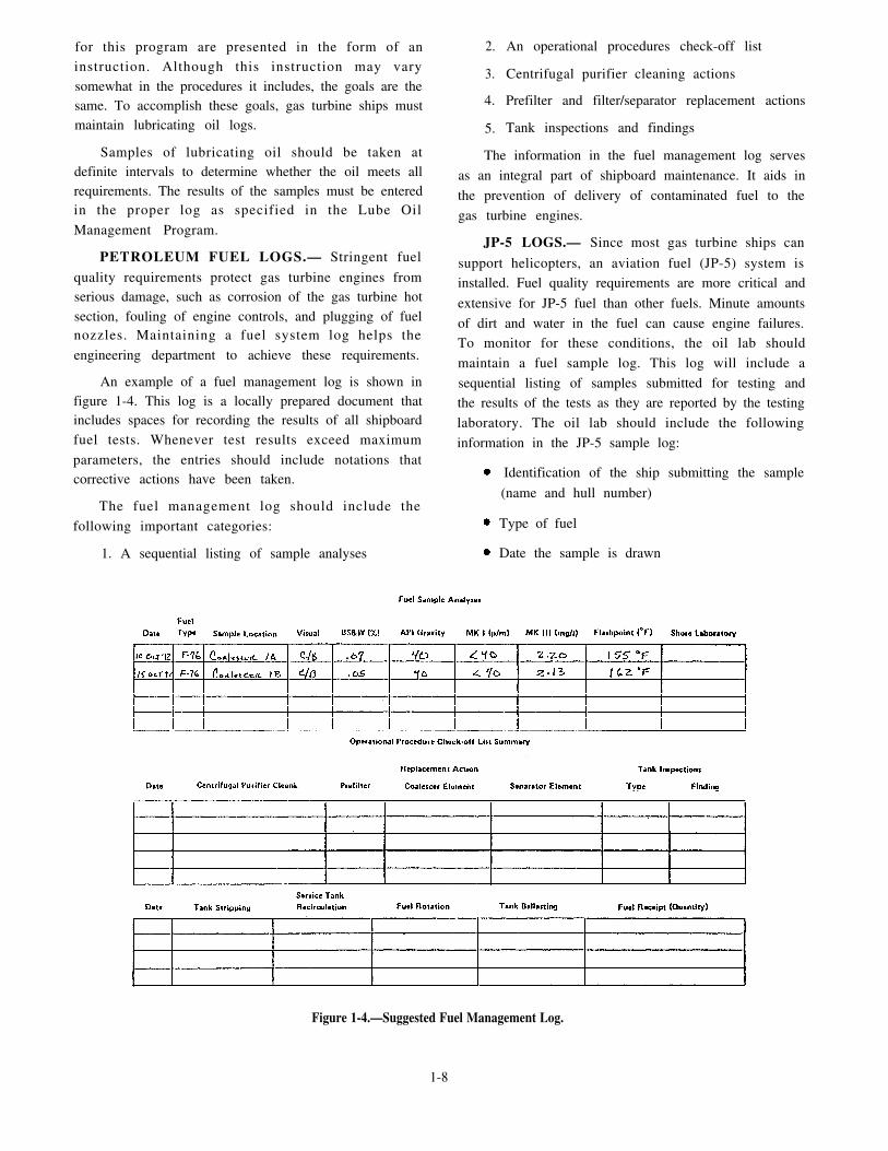
An example of a fuel management log is shown infigure 1-4. This log is a locally prepared document thatincludes spaces for recording the results of all shipboardfuel tests. Whenever test results exceed maximum
parameters, the entries should include notations thatcorrective actions have been taken.
The fuel management log should include the
following important categories:
1. A sequential listing of sample analyses
2.
3.
4.
5.
An operational procedures check-off list
Centrifugal purifier cleaning actions
Prefilter and filter/separator replacement actions
Tank inspections and findings
The information in the fuel management log serves
as an integral part of shipboard maintenance. It aids in
the prevention of delivery of contaminated fuel to the
gas turbine engines.
JP-5 LOGS.— Since most gas turbine ships can
support helicopters, an aviation fuel (JP-5) system isinstalled. Fuel quality requirements are more critical and
extensive for JP-5 fuel than other fuels. Minute amounts
of dirt and water in the fuel can cause engine failures.To monitor for these conditions, the oil lab should
maintain a fuel sample log. This log will include a
sequential listing of samples submitted for testing andthe results of the tests as they are reported by the testing
laboratory. The oil lab should include the following
information in the JP-5 sample log:
Identification of the ship submitting the sample
(name and hull number)
Type of fuel
Date the sample is drawn
Figure 1-4.—Suggested Fuel Management Log.
1-8

Name of the person drawing the sample
Fueling station number or filter/separator
sampled
Heading: Aviation Fuel Sample – Sediment and
Flashpoint
The oil lab uses the fuel sample log in a continuing
shipboard QA program to document the ship’s QA
efforts.
MARINE GAS TURBINE RECORDS.— Equip-
ment records are an essential element of the gas turbine
technical discipline. These records provide a history of
operations, maintenance, and configuration changes of
the equipment. Incomplete or inaccurate records can
cause unnecessary maintenance of equipment. All
activities having custody of marine gas turbine
equipment must maintain service records in a proper and
up-to-date status. Naval Ships’ Technical Manual
The Marine Gas Turbine Equipment Service Record
(MGTESR) is a comprehensive equipment servicerecord. This record is in the form of a looseleaf log
contained within a separate cover and bound in a binder.The cover page of an MGTESR is shown in figure 1-5.
The manufacturer of the equipment starts theMGTESR. The MGTESR is later maintained by the
act ivi ty having custody of the equipment . TheMGTESR a lways r ema ins wi th i t s a s soc i a t ed
equipment. If a gas turbine engine is removed from the
ship, for example, the associated record is transferredwith the engine. The same procedure is followed even
if only one of the removable accessories is removedfrom the engine and shipped for repair. In every case,
the applicable service records must always accompanythe removed items.
The MGTESR binder consists of 10 separate
sect ions, each containing explici t informationconcerning one particular gas turbine engine. The
(NSTM), chapter 234, “Marine Gas Turbines,” includes following list contains the 10 sections of the MGTESR
the procedures your department should follow to binder:
maintain these records. 1. Cover sheet
Figure 1-5.—MGTESR Cover Sheet.
1-9

2. Marine Gas Turbine Engine (MGTE) Custody
and Transfer Record
3.
4.
5.
6.
7.
8.
9.
Card
10.
MGTE Operating Log
MGTE Inspection Record
MGTE Record of Rework
MGTE Technical Directives
MGTE Miscellaneous/History
MGTE Selected Component Record
MGTE Selected Component Record (SCR)
Supplemental records
The following paragraphs will briefly describe the
purpose of each of these sections.
Cover Sheet.— The MGTESR cover sheet is used
only for equipment identification and installation data.
The engine/equipment is identified by serial number.
The installation history entries continue in the spaces
provided to generate a chronological record of nonrepair
activities at which the equipment was installed.
MGTE Custody and Transfer Record.— When anMGTESR is transferred as a part of an equipmenttransaction from one activity to another, the MGTECustody and Transfer Record is completed before thetransfer. (See fig. 1-6.) This record shows who hascustody of the MGTESR and the engine or equipment’scondition (complete/uncannibalized) at the time oftransfer. The commanding officer or the personappointed signs this record.
MGTE Operating Log.— The MGTE OperatingLog shows the total operating time of the engine, startingfrom the time the engine was new. It also shows the timeinterval since the last depot repair or rework wasperformed.
A sample of an MGTE Operating Log is shown infigure 1-7. Notice that the operating time and thenumber of starts must be entered on a daily, weekly, ormonthly basis. You should also note that an engine startis defined as the engine’s successfully going through thestart cycle to idle. Motoring and hung starts should notbe entered in the NO. STARTS column of the log.
MGTE Inspection Record.— Accurate inspectionrecords are a primary requirement, and they prevent theunnecessary reinspection by a new custodian upon
Figure 1-6.—MGTE Custody and Transfer Record.
1-10

Figure 1-7.—MGTE Operating Log.
transfer of an equipment item. The MGTE Inspection You should note that the performance of routine or
Record, shown in figure 1-8, provides for the logging periodic inspection requirements of the Planned
and authenticating of the performance of all special and Maintenance System (PMS) are not recorded on this
conditional inspections performed on the equipment. record.
Figure 1-8.—MGTE Inspection Record.
1-11

Figure 1-9.—MGTE Record of Rework,
MGTE Record of Rework.— The MGTE Record of MGTE Technical Directives.— The MGTE
Rework, shown in figure 1-9, is a complete record of all Technical Directives sheet is a record of technicalr e p a i r , r e c o n d i t i o n i n g , c o n v e r s i o n , c h a n g e , direct ives (TDs) affect ing the equipment andmodernization, or rework performed on the equipment accessories. (See fig. 1-10.) A separate form is used forat a repair or rework facility. each type of TD, and all applicable directives are
Figure 1-10.—MGTE Technical Directives,
1-12

Figure 1-11.—MGTE Miscellaneous/History.
recorded. Gas turbine TDs are issued as gas turbine includes significant details that might beef service tobulletins (GTBs) or gas turbine changes (GTCs). All gas personnel or activities involved in later diagnoses ofturbine TDs, including the irrevisions and amendments, problems with the equipment. The significant detailsshould be recorded by number in this section of the include special test data, abnormal characteristics of theMGTESR. equipment, significant damage or repairs, and engine
MGTE Miscellaneous/History.— The Miscellane-lay-up procedures.
ous/History sheet, shown in figure 1-11, is used in the MGTE Selected Component Record.— T h eMGTESR to record pertinent information for which no MGTE Selected Component Record, shown in figureother place has been provided. This information 1-12, maintains a current inventory and installation and
Figure 1-12.—MGTE Selected Component Record.
1-13

Figure 1-13.—MGTE Selected Component Record Card.
removal record for all equipment accessories and
components that require selected component record(SCR) cards. When a selected component is replaced,
the removal data for the removed component andinstallation data for the new component is entered in thisrecord.
MGTE Selected Component Record Card.— For
any equipment item, the continuity of historical data isessential. The MGTE Selected Component Record
(SCR) Card, shown in figure 1-13, provides for therecording of installation and removal data, TD status,
and repair/rework historyon selected accessories and
components. When a component is removed from theequipment, the corresponding SCR card is removedfrom the MGTESR. This procedure ensures the
continuity of important historical data.
Supplemental Records.— The two supplementalrecords required in the MGTESR are shown in
figure 1-14. These records are the MGTE Turbine Rotor
Disc Assembly Service Record and the MGTE
Compressor Rotor Assembly Service Record. When a
turbine rotor disc assembly is to be reworked, the rework
activity must ensure that data associated with each disc
is properly recorded. The same requirement is true if the
compressor rotor assembly is reworked. Although one
record is required for each turbine rotor disc or stage$
only one record is required for the complete compressor
rotor assembly.
DIESEL ENGINE RECORDS.— As a GSE2 on
board an FFG-7 class ship, you can expect to review
diesel engine records. The repair and history records are
primarily for the operating personnel of the ship. They
will prove valuable in making estimates of parts needed
and work lists for the next availability. A system must
be setup by which completely accurate and up-to-date
records can be kept on all diesel engines.
1-14
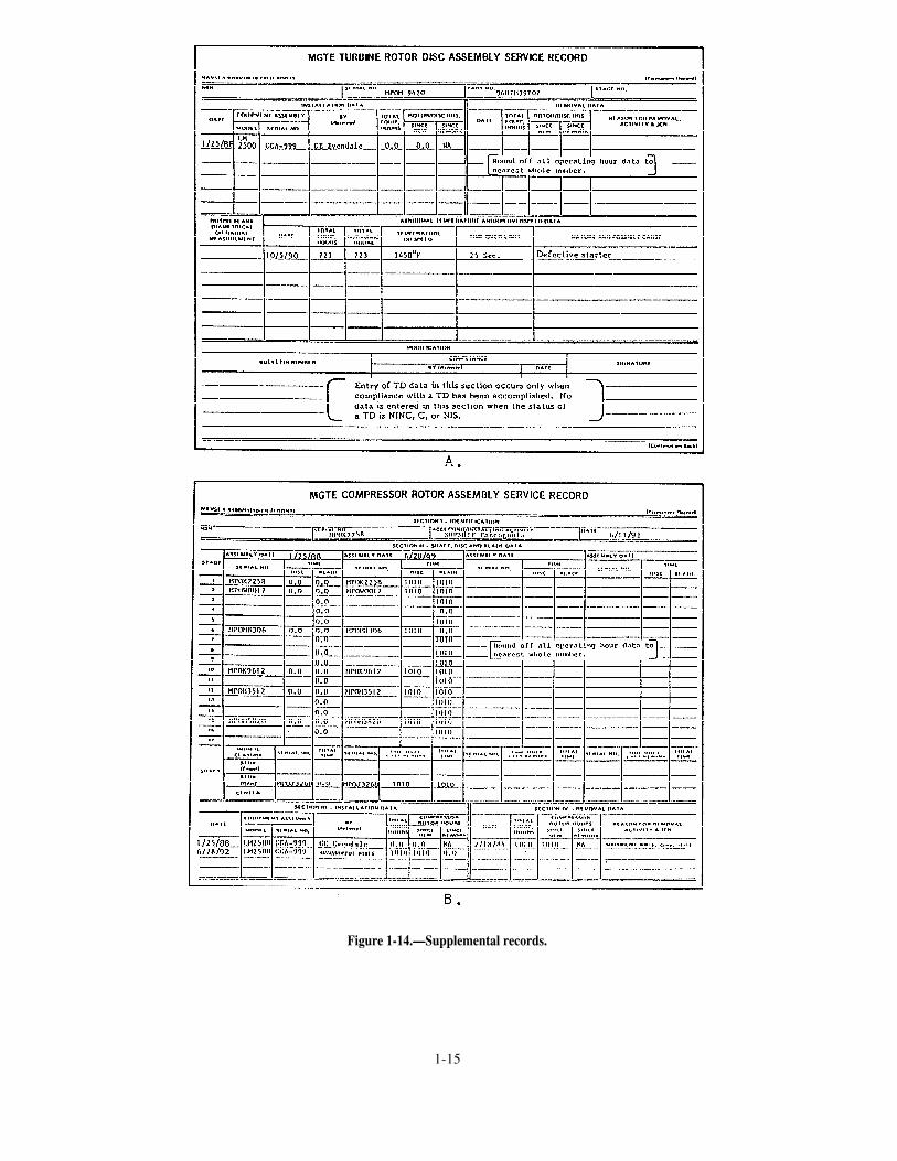
Figure 1-14.—Supplemental records.
1-15

Figure 1-15.—Diesel Engine Operating Record—All Ships.
The Diesel Engine Operating Record, shown infigure 1-15, is a daily record maintained for eachoperating diesel engine. For ships with more than onediesel in the same machinery room, a separate recordsheet is maintained for each operating diesel engine. Thewatch supervisor enters the remarks and signs the recordfor his or her watch. The engineer officer immediatelyreceives a report of any unusual conditions noted in therecord. The engineer officer then receives the record forhis or her approval.
REDUCTION GEAR RECORDS.— Maintaininga log for the main reduction gear is extremely important.This log should be kept in the engine room and thereadings must be taken and recorded at establishedintervals. A reduction gear log serves as a guide indetecting unusual and inefficient operating conditions.Temperatures, pressures, and the presence of oil in the
sight flow indicators are important readings that shouldbe included on this log.
1-16
AIR COMPRESSOR RECORDS.— A typical air
compressor Operating Data Log Sheet is shown in
figure 1-16. This log is kept by the operator who takes
and records readings at established intervals. For
extended operation, a data log sheet should be filled out
during every watch. A log is helpful not only from the
operational and maintenance standpoints but also as a
troubleshooting guide for detecting unusual and
inefficient operating conditions.
Depending on the ship’s air system demand, the
actual operating time on each compressor of a
multicompressor installation might differ. For each
compressor to provide the best service, the operating
time should be equalized over each quarterly period.
Reviewing the entries on these logs and noting the hours
recorded will allow the operators to change the
operating sequence of the units accordingly.

Figure 1-16.—Typical Compressor Operating Data Log.
DISTILLING PLANT OPERATING REC-
ORD.— The Distilling Plant Operating Record is a dailyrecord of the operating ship’s evaporators and their
auxiliaries. Entries are made for each hour while the
distilling plant is operating. Different gas turbine ships
have many different types of distilling plants, but all
daily distilling plant operating records will require
practically the same type of data entries. The following
list includes the required information:
1. Temperature, pressure, vacuum, flow, chemical
analysis, and density data from various points in the
distilling plant
2. Scal ing record for each evaporator uni t ,
including the date of the last scaling, the hours operated,
and the quantity of distilled water produced since the
last scaling to the day of the record and since the lastscaling to the end of the day record
3. Starting, stopping, and total operating time ofeach evaporator and various auxiliary machinery parts,such as air ejector and pumps
4. Remarks about the operation and maintenanceof the distilling plant for each watch of the day
You must make accurate entries in the DistillingPlant Operating Record. Accurate entries will helppredict trouble. If abnormal operating conditions shouldsuddenly develop, the entries in the record should aid inlocating the sources of trouble.
R E F R I G E R A T I O N / A I R - C O N D I T I O N I N G
RECORDS.— Your department will use the dailyo p e r a t i n g l o g f o r r e f r i g e r a t i o n e q u i p m e n t o r
1-17

air-conditioning plants to maintain a record of operating The information in this log provides a method forconditions. The log, shown in figure 1-17, is a guide for engineering personnel to determine when and whatthe continued analysis of operating conditions and corrective measures are necessary when a plant is notoperating results found in the equipment. Notice that operating properly. Data taken at various points in thedata entries are made on both sides of the form. (See system are compared with corresponding data takenviews A and B.) during normal plant operation. The corresponding data
Figure 1-17.—Refrigeration/Air-Conditioning Equipment Operating Log.
1-18

must be taken under the same heat load and circulatingwater temperature conditions.
Daily Reports and Records
Maintenance of daily fuel, lubricating oil, and wateraccounts is essential to the efficient operation of theengineering department. The TYCOMs prescribe theforms and procedures necessary to account for freshwater and fuel. These reports and records inform theengineer officer of the status of the ship’s liquid load andform the basis of several important reports, which aresent to higher authority. The most important of thesereports is the report of the amount of burnable fuel onhand.
FUEL AND WATER REPORT.— The Fuel andWater Report, shown in figure 1-18, is a daily report ofthe fuel and water status prepared to reflect theseconditions at 0000 hours. The commanding officerreceives this report daily. The report contains data, suchas total fuel and total lube oil on board and the amountof potable water and reserve feedwater on board. TheFuel and Water Report also includes the previous day’sfeedwater and potable water consumption figures andthe results of the water tests. The officer of the deck
(OOD) receives the original copy in time for submissionto the commanding officer or command duty officerwith the 1200 reports. The OOD retains the copy.
DAILY WATER ACCOUNT.— Some gas turbineships maintain a Daily Water Account. The Daily WaterAccount is a daily record of the feedwater for the boilersand the potable fresh water in the potable water tanks.The data are recorded on the form by the oil king andchecked for accuracy by his or her leading petty officer.The division officer also checks the form. Whencompleted and checked, the record is submitted to theengineer officer for his or her approval and signature.
DUTIES, RESPONSIBILITIES, ANDREQUIREMENTS
From reading this chapter, you should recognizethat there are many logs and records engineeringdepartment personnel are required to maintain. Theresponsibilities only begin with the accurate recordingof data for the machinery and equipment. The entriesmust be made not only in the proper logs or records butalso in the appropriate sections of these logs or records.One of the most important responsibilities will beverifying the accuracy of these entries. The importance
Figure 1-18.—Fuel and Water Report.
1-19

of this responsibility should not be underestimated.Engineering personnel will base their determinations inregard to the condition of the equipment on theinformation contained in these logs and records.
Verification Procedures
As you advance in the GSE rating, you will berequired to verify many of the engineering logs andrecords. In fact, you may be required to review manylogs and records on a daily basis. In reviewing logs andrecords, there are certain details you should look for andtake note of. Although each situation or type of log orrecord may have its own set of required procedures, thefollowing list contains a few of the most important basicdetails for which you should check:
All readings and entries must be legible.
All entries must be placed in the proper locationin each log.
Out-of-limits entries must be circled in RED andexplained in the REMARKS section of the logs.
All required initials and signatures must bepresent.
All logs and records must be free of erasures.
All required logs and records must be present.
As stated earlier, the verification process is one ofthe most important responsibilities you will face as youadvance in the GSE rating. Another important part ofyour increasing administrative duties will involvelearning the correct disposal procedures for the recordsyour department will no longer need to keep.
Disposal Procedures
Before destroying any engineering departmentrecords, study the Disposal of Navy and Marine CorpsRecords, USN and USNS Vessels, S E C N A V I N S TP5212.5 (revised). This publication provides the officialprocedures for disposing of records. For eachdepartment aboard your ship, these instructions list thepermanent records that must be kept. The instructionsalso list the temporary records that maybe disposed ofaccording to schedule.
At regular intervals, such as each quarter, recordsthat are more than 3 years old are usually destroyed.When a ship that is less than 3 years old isdecommissioned, the current books are retained onboard. If a ship is scrapped, the current books are sent
to the nearest naval records management center. Allreports sent to, and received from, NAVSEA or anothersuperior command may be destroyed when they are 2years old, if they are no longer required.
To control the volume of paper work, reports shouldbe kept on board only if they are
1. required,
2. serve a specific purpose, or
3. provide repair personnel with information notfound in other available publications or manuals.
As you assume more extensive administrativeresponsibilities, you will be required to becomeincreasingly aware of the retention, disposal, andmaintenance procedures required for your department.
FILES AND TICKLER SYSTEMS
As a second class GSE, you will be required to learnhow to maintain correspondence files, messages, andtickler systems. You will need to determine therequirements of your division. You should know how toset up the files, what to file, and how to use the files togather necessary information. You will also need tomake sure that information your division develops issent to higher authority in the proper form of reports orpackages.
The accuracy of a filing system and the ease inretrieving information is extremely important if thesystem is to be effective. Administration of theengineering department requires easy access to previousinformation either received or sent out. Efficientlymanaged files contribute directly to the overalleffectiveness of the engineering department.
Each month the engineering department shouldclose out the files, logs, and records of the previousmonth. This means a new set is needed for each newmonth. When starting up a new month’s logs, records,and files, always take a look at last month’s logs,records, and files. Determine which logs, records, orfiles were bulky and which contained only a few piecesof paper. Use this information to set up your new folders.Some files may have to broken down to make themquicker to find. Some files may be combined to savespace.
One final decision to make when setting up files ishow to keep your logs, records, and files centralized.This step will help you prevent a backlog of requests forinformation or delays when you must produce aparticular log or record.
1-20

Efficiency can be maintained by a thorough trainingprogram for all engineering personnel involved in logkeeping. If all personnel are familiar with the filingsystem, they will place the logs and records in the properlocation.
As a GSE2, you will likely be assigned to maintaina variety of files. Most routine files will involve thosefor correspondence, messages, or tickler systems. Eachof these categories is briefly described in the followingsections.
Correspondence
Correspondence includes all written material–publications, messages, memoranda, and so on–sent toand from a command. You must read and understandthese types of correspondence. The system used to fileyour division’s correspondence should be one that allpersonnel can use.
Messages
Messages are the quickest form of wri t tencommunication in the Navy. This is because ourtelecommunications system is capable of gettingtime-sensitive or critical information to addressees
rapidly for effective use of information. There areseveral methods used to file messages. Your divisionmay file messages according to date-time group (DTG),
precedence category, or subject matter. You should learnyour division’s message filing system to help you locatecritical information.
Tickler Systems
A tickler system consists of record cards, usuallyorganized in a standard desk-top box, in chronologicalor alphabetical order. This system makes handlingrecurring reports simpler. The reports tickler filerequires daily attention if it is to be an effective tool. Youmust keep it and the information it contains up to date,and you must inform responsible personnel of currentrequirements for reports.
PMS FEEDBACK FORMS
The PMS Feedback Report (FBR) is a form shipsuse t o no t i fy t he Nava l Sea Suppor t Cen t e r(NAVSEACEN) or the TYCOM of matters related toPMS. The FBR is a five-part form composed of anoriginal and four copies. A completed FBR is shown infigure 1-19. The front side, shown in view A, is used for
Figure 1-19.—PMS Feedback Report.
1-21

data describing a specific PMS problem. The reverseside of the last copy, shown in view B, providesinstructions for preparing and submitting the form. Asyou advance in the GSE rating, you will prepare, submit,and review several FBRs. The following informationwil l help you understand your responsibi l i t iesconcerning the FBR.
Preparation Procedures
When a PMS-related problem occurs, you shouldtry to correct the problem, especially if it presents asafety hazard. The PMS FBR is your vehicle for thesolution to the problem. To prevent delays in correctingthe problem, however, you should make certain tocomplete and submit the form correctly according to theinstructions on the back.
Once you identify a PMS problem, you shouldimmediately start entering the documentation on theFBR. You can either use a typewriter or neatly handprintyour entries. Remember to insert your ship’s name andhull number. Leave the date and serial number blank.The 3-M coordinator will insert the information in thesetwo blocks.
Next, you must determine what category yourparticular problem is assigned to. There are twocategories of FBRs—Category A and Category B. Thesecategories are defined as follows:
Category A–This category is nontechnical innature and meets PMS needs that do not requiretechnical review. The FBRs assigned thiscategory pertain to the need for replacement ofmissing or mutilated maintenance index pages(MIPs) or maintenance requirement cards(MRCs).
Category B–This category is technical in nature.It is submitted by the ship’s 3-M coordinator tothe applicable TYCOM. FBRs assigned thiscategory pertain to the notification of a shift inmaintenance responsibilities from one workcenter to another. These FBRs also pertain toTYCOM assistance in the clarification of 3-Minstructions. This category also applies tot echn ica l d i s c repanc ie s i nh ib i t i ng PMSperformance. These discrepancies can exist indocumentation, equipment design, maintenance,r e l i a b i l i t y , o r s a f e t y p r o c e d u r e s . T h ediscrepancies can be operational deficiencies inPMS support (parts, tools, and test equipment),as well.
NOTE
When the reason for submission of a PMS FBRinvolves safety of personnel, or potential fordamage to equipments, and relates to thetechnical requirements of PMS, the FBR isconsidered URGENT. Urgent FBRs must besent by naval message to both NAVESEACENSwith information copies to the cognizant SYS-COM/BUMED/NAVSAFECEN/TYCOM.
Your next s tep is to f i l l in the equipmentidentification section. This information consists ofsystem, subsystem, or component, allowance parts list(APL), MIP number, and MRC control number. Underthe DESCRIPTION OF PROBLEM section, check theproper block under either Category A or Category B. Inthe REMARKS section, provide a brief description ofthe problem or requirement. Remember to includesufficient information to describe the problem. Next,insert the work center code and sign the FBR. The FBRwill then be routed through your chain of command forreview and approval.
Review Procedures
Before sending your FBR through the chain ofcommand, you should review the form for completenessand accuracy. One section you should closely scrutinizeis the equipment identification section. Errors in thissection will cause delays in processing your FBR.Provide as much information as you can. Make certainyou use the correct APL number for hull, mechanical,or electrical equipment. Read the comments in theREMARKS section. Make certain the comments arelegible and complete. On handwritten FBRs, be sureeach copy is clear and legible. Observation of thesesimple guidel ines wil l help you maintain yourequipment in a high state of readiness.
EQUIPMENT GUIDE LIST
The Equipment Guide List (EGL) is a 5" x 8" cardthat is used with a controlling MRC. (See fig. 1-20.)When the MRC applies to the same type of items(motors, controllers, valves, test equipment, and soforth), use an EGL card. Each ship prepares its ownEGLs. Standard EGL forms are available from the Navysupply system.
When determining the number of items to includeon an EGL, you should consider the skill level of theassigned maintenance person and the time that will berequired to complete the maintenance on each item.
1-22
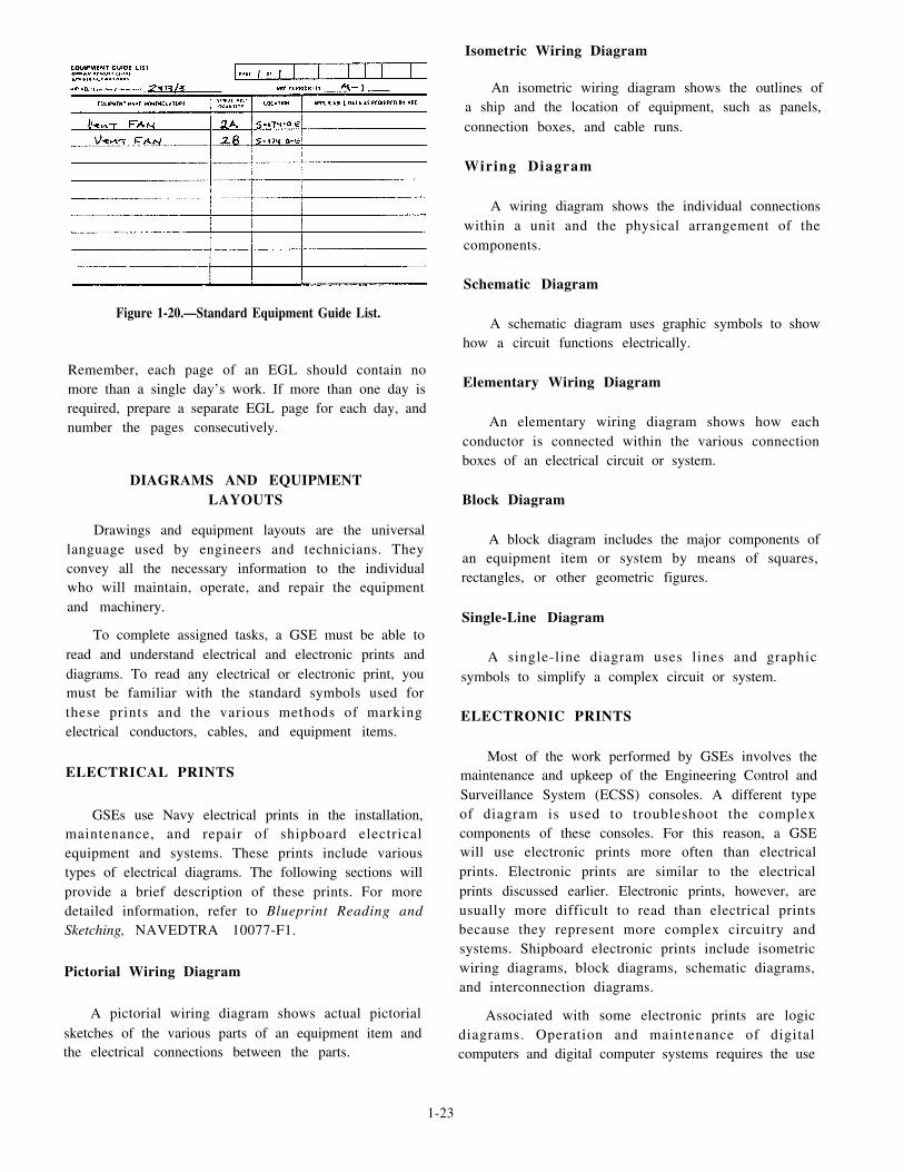
Figure 1-20.—Standard Equipment Guide List.
Remember, each page of an EGL should contain nomore than a single day’s work. If more than one day isrequired, prepare a separate EGL page for each day, andnumber the pages consecutively.
DIAGRAMS AND EQUIPMENTLAYOUTS
Drawings and equipment layouts are the universallanguage used by engineers and technicians. Theyconvey all the necessary information to the individualwho will maintain, operate, and repair the equipmentand machinery.
To complete assigned tasks, a GSE must be able toread and understand electrical and electronic prints anddiagrams. To read any electrical or electronic print, youmust be familiar with the standard symbols used forthese prints and the various methods of markingelectrical conductors, cables, and equipment items.
ELECTRICAL PRINTS
GSEs use Navy electrical prints in the installation,maintenance, and repair of shipboard electricalequipment and systems. These prints include varioustypes of electrical diagrams. The following sections willprovide a brief description of these prints. For moredetailed information, refer to Blueprint Reading andSketching, NAVEDTRA 10077-F1.
Pictorial Wiring Diagram
A pictorial wiring diagram shows actual pictorialsketches of the various parts of an equipment item andthe electrical connections between the parts.
Isometric Wiring Diagram
An isometric wiring diagram shows the outlines ofa ship and the location of equipment, such as panels,connection boxes, and cable runs.
Wiring Diagram
A wiring diagram shows the individual connectionswithin a unit and the physical arrangement of thecomponents.
Schematic Diagram
A schematic diagram uses graphic symbols to showhow a circuit functions electrically.
Elementary Wiring Diagram
An elementary wiring diagram shows how eachconductor is connected within the various connectionboxes of an electrical circuit or system.
Block Diagram
A block diagram includes the major components ofan equipment item or system by means of squares,rectangles, or other geometric figures.
Single-Line Diagram
A single-line diagram uses lines and graphicsymbols to simplify a complex circuit or system.
ELECTRONIC PRINTS
Most of the work performed by GSEs involves themaintenance and upkeep of the Engineering Control andSurveillance System (ECSS) consoles. A different typeof diagram is used to troubleshoot the complexcomponents of these consoles. For this reason, a GSEwill use electronic prints more often than electricalprints. Electronic prints are similar to the electricalprints discussed earlier. Electronic prints, however, areusually more difficult to read than electrical printsbecause they represent more complex circuitry andsystems. Shipboard electronic prints include isometricwiring diagrams, block diagrams, schematic diagrams,and interconnection diagrams.
Associated with some electronic prints are logicdiagrams. Operation and maintenance of digitalcomputers and digital computer systems requires the use
1-23

Figure 1-21.—Basic logic diagram.
of logic diagrams. There are two types of logic
diagrams-basic and detailed.
Basic logic diagrams show a particular operatingunit or component. Figure 1-21 is an example of a basic
logic diagram. In a basic logic diagram, basic logic
symbols are shown in their proper relationship to show
operation only in the most simplified form.
Detailed logic diagrams show all logic functions ofthe equipment concerned. In addition, they also includesuch information as socket locations, pin numbers, andtest points to ease troubleshooting. A detailed logicdiagram for a complete unit may consist of manyseparate sheets. An example of a detailed logic diagramis shown in figure 1-22.
EQUIPMENT LAYOUTS
Engineering personnel use equipment layouts asaids to locate various pieces of equipment throughout amachinery space. Equipment layouts are extremelyhelpful to newly reporting personnel who are notfamiliar with the engineering spaces. The main purposeof an equipment layout is to show the physicalrelationship of the equipment to its location in a space.Some layouts are more detailed than others, but theprimary purpose is the same. While some equipmentlayouts may show only the physical location ofmachinery, others will show the piping that connectsvarious pieces of equipment together.
Figure 1-22.—Detailed logic diagram.
1-24

On a gas turbine-powered ship, you will primarilyfind equipment layouts in the Engineering OperatingProcedures (EOP). The equipment layouts in the EOPare used mainly for training new personnel. To be ableto use an equipment layout for system tracing dependsupon the amount of detail included in the equipmentlayout.
SUMMARY
This chapter has provided you with a variety ofinformation to help you become a more efficient andeffective gas turbine specialist.
This chapter described the Navy’s QA program and
how you, a work center supervisor, will become
involved in this program. This chapter also described
the engineering administration system. The preparation
procedures for various operating logs and records were
discussed along with general guidelines for maintaining
files, correspondence, and messages. This chapter also
described preparation and submission procedures for
PMS FBRs and the various uses of diagrams and layouts
you will encounter as a GSE.
1-25


CHAPTER 2
UNINTERRUPTED POWER SUPPLY SYSTEMS
The propulsion control consoles on gas turbine-powered ships require a constant power source. Most ofthese consoles cannot withstand an interruption of thispower source. If power is removed, the main fuel valveon the GTE will close, causing the GTE to shut down.This is why an uninterrupted power supply to the controlconsoles is so important. It keeps the engineering plantoperating at maximum efficiency.
Gas turbine-powered ships are equipped withbattery backup systems. These systems provide analternate, short-term power source to vital pieces ofequipment when a failure of normal ship’s servicepower occurs. The control consoles, especially, willrequire an immediate source of backup power. Becausethe battery backup system must have a rapid method oftransferring the load to the backup, electronic switchingis used. Electronic switching allows backup power inthe form of an uninterrupted power supply to be sent tothe control consoles. Consequently, the battery backupsystem used on gas turbine-powered ships isappropriately called the uninterrupted power supply(UPS).
The UPS systems used on gas turbine-poweredships will be different for each class of ship. The mainpurpose for all UPS systems, however, is the same: tosupply backup power to vital equipment when thenormal power supply fails. In the following paragraphs,we will briefly discuss the operation and components ofthese systems and the different configurations you willfind among the different classes of ships.
DD-963, DDG-993, AND CG-47 CLASSSHIPS
The UPS system for DD-963, DDG-993, andCG-47 class ships supplies emergency dc power tomaintain operation of critical ship control systemsduring loss of normal ac power. The UPS can supply anominal value of 150 volts dc to the control consoles forabout 30 minutes.
Figure 2-1 shows a typical UPS system used onDD-963, DDG-993, and CG-47 class ships. The UPSoriginates from a bank of lead-acid storage batterieslocated in the ship’s control UPS battery room. This
Figure 2-1.—Diagram of UPS system for DD-963, DDG-993, and CG-47 class ships.
2-1

equipment consists of a regulated battery charger, abattery rack, and a distribution panel.
You can monitor UPS voltage by using the meterslocated on the electric plant control console (EPCC) andthe battery charger. You can also dial up the UPS batteryvoltage on the demand display indicators (DDIs). Thenominal voltage is 150 volts dc. If this voltage dropsbelow 122 volts dc, an alarm will sound at the EPCC.The EPCC also has an indicator light that illuminateswhen the battery charger is active. The 150 volts dc istransformed by dc-to-dc converters to different dcvoltage levels required by the consoles. An inverterproduces 115 volts ac to run each power supply coolingfan and for GTE igniter power.
The battery charger maintains a floating charge onthe battery bank. With current limited to 30-amperes, adischarged battery bank can be recharged within 8hours. Realize, however, that the engineering controland survei l lance system (ECSS) does not ful lydischarge the batteries. If the dc bus voltage drops below120 volts, the power supplies will shut down. Thebattery charger input power is 450 volts ac, 60 hertz(Hz). It originates from the main switchboard through avital propulsion power panel.
Nine lead-acid batteries are mounted in a rack in thebattery room. Eight of the batteries are connected inseries and the ninth battery is a spare. The shelf life ofthe spare battery is about 1 year, after which time thebattery charger cannot reactivate the battery to fullcharge. Special attention should be given to batterymaintenance as the UPS batteries are of special design.
The distribution panel circuit breakers are normallyleft closed, and UPS power is available at the consolepower supplies. The console power supplies are locatedin the respective electronics enclosures. When normalac power is lost at the power supplies, the dc power
requirements will automatically be transferred onto theUPS. Indicator lights at each console will illuminatewhen the console is operating on UPS. After about 3minutes of operation on UPS, internal supplies will shednoncritical loads within the console.
The UPS battery charger is interlocked through thebattery room exhaust ventilation controller. The batterycharger will shut down if the ventilation is lost. This isa necessary safety feature because charging batteriesproduce dangerous amounts of hydrogen.
FFG-7 CLASS SHIPS
The UPS on the FFG-7 class ship furnishesmaximum continuity of service for the propulsion andelectric plant control system. The UPS is a self-contained unit that consists of five major components.As shown in figure 2-2, these components are asfollows:
A 120-volt dc to 120-volt ac, 60-Hz inverter
A 120-volt dc battery charger/rectifier
A solid-state automatic load transfer switch
Control equipment
A 120-volt dc battery bank (not in the unit)
The UPS is located in the engine room. It isenergized from the engine-room lighting panel. Normaland a l t e rna t e power f rom the sh ip ’ s s e rv i ceswitchboards is provided by an automatic bus transfer(ABT). There are 20 6-volt lead-acid storage batterieslocated in the engine room. The UPS is connected inseries with the load and is designed to be continuously
Figure 2-2.—Diagram of UPS system for FFG-7 class ships.
2-2

energized from the ship’s 120-volt ac, 3-phase, 60-Hzpower source.
The battery charger/rectifier is connected tomaintain the charge of the ship’s battery bank whilesimultaneously supplying power to the inverter. Uponfailure of the ship’s ac input to the UPS, power from theship’s battery bank will automatically provide dc powerto drive the inverter. This causes the inverter to maintainthe ac output to the load without power interruption forup to 15 minutes. When the ship’s ac input returns, thebattery charger/rectifier of the UPS will supply theinverter and charge the battery bank. The transfer ofpower to and from the battery bank takes place withoutany interruption of power.
The ship’s service 120 volts ac is supplied througha circuit breaker to a transformer and then rectified toproduce the 120 volts dc. The 120 volts de is applied toan oscillator and a single-phase bridge inverter. The120-volt ac, 60-Hz, 1-phase output of the inverter is thenormal input to the automatic load transfer switch. Tosupply power if the inverter fails, one phase of the ship’s120-volt ac, 3-phase power supply is routed to thealternate input to the automatic load transfer switch.
The control devices of the UPS consist of afour-position mode switch and a two-position ON-OFFs w i t c h . T h e m o d e s w i t c h s e l e c t s N O R M A L ,ALTERNATE, AUTOMATIC, or OFF. NORMALselects inverter output only and ALTERNATE selectsship supply output only. AUTOMATIC selects thetransfer switch selected output and OFF removes UPSfrom the output circuit breaker.
When it is in the ON position, the ON-OFF switch
connects 120 volts dc to the oscillator. The 120 volts dc
must be applied to the oscillator before the 120 volts dc
is energized to the inverter. The 120 volts dc must
remain on until after the inverter is de-energized to avoid
possible damage to the parts of the inverter.The ship’s UPS battery bank is connected to the
battery charger/rectifier by a circuit breaker. The output
from the battery charger/rectifier maintains the charge
on the batteries during regular conditions. The batteries
may be discharged while they are supplying 120 volts
dc to the inverter if the ships’s service power to the UPS
is de-energized. When ship’s service power returns to
the UPS, it allows the battery charger/rectifier to
recharge the battery bank to full charge.The UPS system is equipped with instrument and
indicator light monitoring devices. These devices
provide a continuous visual display of the UPSoperation. They consist of power available indicators, a
battery bank voltmeter, a battery ammeter, and two
oscillator-inverter status indicator lights. The system
also contains four devices that show the UPS outputpower condition and three indicator lights that show
which power source is supplying the load.
DDG-51 CLASS SHIPS
Figure 2-3 shows a block diagram of the UPS
system used on DDG-51 class ships.
Figure 2-3.—Block diagram of the UPS system for DDG-51 class ships.
2-3

All machinery control system (MCS) consoles,except the bridge control unit (BCU), are protected froma loss of 155-volt dc electrical power. The UPS batterycells located in each console provide this protection. Thecapacity of the multicell battery pack powers itsconnected units for at least 30 minutes following apower failure. The batteries are contained in fumetight,
slide-mounted assemblies that are vented outside theMCS consoles. Each console has from one to three racksof cells, depending on its power requirements. Thebattery-charging circui ts of each console canautomatically recharge a battery from 40 percentcapacity to 80 percent capacity within 8 hours. Batterycharging does not affect normal MCS operation.
The interim integrated electronic control (IIEC)also includes an UPS battery pack system. The IIECcontains the electronic support module (ESM) and theengine control module (ECM). (See fig. 2-4) The IIECperforms functions similar to those of the free standingelectronics enclosure (FSEE) on other gas turbine ships.The battery pack for the IIEC is contained in the ESM.The ECM also uses the UPS battery pack that iscontained in the ESM.
The MCS consoles require single-phase and3-phase, 115-volt ac, 60-Hz power. The single-phasepower energizes the console heating elements wheneverthe 3-phase power is not in use. The normal powersource for each MCS console is the 3-phase, 115-voltac. Its use raises console temperatures above expecteddew point levels, avoiding hardware problems. Theheating elements maintain the protected environmentwhen the consoles are off-line.
T h e M C S c o n s o l e b a t t e r y c h a r g e r w i l lautomatically shift the load to battery power when thenormal power supply fails. The batteries, located in thelower section of the console, are a 155-volt dc source.When the shift to UPS power occurs, an alarm willsound and the UPS IN USE indicator on the console willilluminate. A message showing that a particular consoleis on UPS will be displayed on the plasma display units.The UPS is designed to supply needed power for aminimum of 30 minutes.
Normal or UPS battery power enters the console
power distribution system through the power controlpanel assembly. Three-phase voltage is rectified to +155volts dc in the power conditioner and sent to the batterycharger. This normal 155-volt dc power automatically
charges the UPS batteries and provides input to thepower supplies. The UPS battery power is connected tothe power supplies when the load shifts. The battery
Figure 2-4.—Electronic support module (ESM).
charger assembly logic is designed to use the normal
power source when it is available.
BATTERY MAINTENANCE
You must give the same careful attention to the
maintenance of UPS batteries that you would to the
maintenance of any other power unit. Lack of intelligent
supervision in the care of a UPS battery can result in
temporary impairment or permanent damage. Carefully
follow all instructions contained in the maintenance
requirement cards (MRCs), manufacturer’s technical
manual, and data on the battery nameplates. These
instructions will help you make sure the batteries
perform as designed. In the following paragraphs, we
will briefly discuss some of the maintenance tasks and
procedures you will use with the UPS battery systems.
2-4

STATE OF CHARGE
The specific gravity of the electrolyte graduallydecreases on discharge and gradually increases oncharge. This decrease or increase is directly proportionalto the number of ampere-hours taken out of or put intoa battery. You can determine the state of charge of avented battery, where the electrolyte is accessible, bytesting the specific gravity of the electrolyte. The onlyway you can determine the state of charge of a sealedbattery is by measuring its open-circuit voltage.
CHARGING
Except in an emergency, do not charge batteries inan enclosed space, unless the space has adequateventilation. Stop charging if ventilation is interrupted.Do not resume charging until ventilation is restored. TheUPS system on gas turbine-powered ships is interlockedwith the ventilation system. If ventilation is interrupted,the UPS charging system will shut down.
Before starting a charge, make sure the electrolyteis at the proper level. The proper electrolyte level isabout 3/8 inch above the plates or separators. If theelectrolyte is too high, it will flood out of the filling tubesduring the charge. This is caused by the expansion thattakes place inside the cell as the temperature rises andby gassing. If the electrolyte gets too far below the topof the plates or separators and remains there, theexposed parts will dry and harden and will no longerfunction. This will cause a reduction in capacity andshorten the life of the battery.
SAFETY CONSIDERATIONS
Since a certain amount of gas is always given offfrom a vented battery, flames or sparks of any kind mustnever be allowed near any storage battery. Extra care isnecessary after opening a battery compartment that hasbeen sealed. No light switches should be turned on, noelectrical connections of any kind should be made orbroken, and no work should be performed in thecompartment until it has been ventilated.
To prevent electrolyte from spraying out or foreignmatter from entering the battery, always keep the ventplugs in place. You can remove the vent plugs whentaking temperature and specific gravity readings oradding water. Always keep the vent hole free ofobstructions.
All batteries and battery lockers must be kept cleanand free of foreign matter. Clothing, cloth, or wipingrags should not be allowed to remain in battery lockers.When vent plugs are removed from cells, you mustprevent anything from falling into the battery cell. Youshould avoid spilling acid or water in battery rooms.Collections of acid or dirt around a battery will lead totrouble and will cause corrosion. After adding water tothe batteries, wipe the tops of the cells and the sides ofthe batteries clean. If acid has collected on the case,remove it by wiping the case with a cloth moistened ina diluted ammonia solution or bicarbonate of sodasolution. While using ammonia or bicarbonate of soda,make sure the solution does not enter the battery cells.
SUMMARY
In this chapter, we have discussed the UPS systemsused on the different classes of gas turbine-poweredships. We have also discussed some of the basicmaintenance and safety procedures you should usewhen operating and maintaining the UPS system onyour ship.
The conditions under which the UPS batteries areused vary from ship to ship. The frequency of inspectionand maintenance necessary to ensure that the UPSbatteries are in good operating condition will also vary.For detailed maintenance procedures associated withthe UPS batteries, refer to the appropriate technicalmanuals.
As a GSE, you will find that your involvement withthe UPS system will vary from ship class to ship class.On some ships, the maintenance of the complete UPSsystem will be your responsibility. However, on otherships you may be responsible for only the dc power atthe power supplies. In any case, this chapter should haveprovided you with a basic understanding of the UPSsystems found on gas turbine-powered ships.
2-5


CHAPTER 3
ENGINEERINGCONTROL SYSTEM OPERATION
One of the most remarkable design features of a gas
turbine-powered ship is the fact that the engineering
plant can be operated, monitored, and controlled from a
central area located away from the actual equipment and
systems. The engineering control system makes this
possible. Currently, three major designs of engineering
control systems exist for gas turbine ships. The DD-963,
DDG-993, and CG-47 class ships use the engineering
control and surveillance system (ECSS) to operate the
gas turbine equipment. The FFG-7 class ships use the
engineering plant control system to both operate and
monitor the gas turbine equipment. The relatively new
DDG-51 class ships use the machinery control system
(MCS) to both control and monitor the gas turbine
equipment.
After reading this chapter and completing the
associated nonresident training course (NRTC), you
should have a good understanding of the function and
operation of the major engineering control systems used
on gas turbine-powered ships. Remember, this material
is meant for training purposes only. It is not meant to
replace the engineering operational sequencing system
(EOSS) or the technical manuals.
The con t ro l conso l e s a s soc i a t ed w i th t he
engineering control systems will not be discussed, in
depth, in this chapter. Gas Turbine Systems Technician
(Electrical) 3/Gas Turbine Systems Technician
(Mechanical) 3 , Volume 2, contains a detai led
description of the control consoles used on gas
turbine-powered ships.
After reading this chapter, you should be familiar
with the operation of the engineering control systems
and be able to discuss how they relate to the engineering
plant. While you may never work on all types of control
systems, this chapter should provide you enough
information to help you advance in rate. As you become
senior in the GS rating, this introduction to engineering
control systems will be helpful in your watch-station
qualifications.
ENGINEERING CONTROLAND SURVEILLANCE SYSTEM(DD-963, DDG-993, AND CG-47
CLASS SHIPS)
The ECSS is the automated electronic control andmonitoring system used on the DD-963, DDG-993, andCG-47 class ships. This system uses both analog anddigital circuitry. The ECSS can control the propulsionplant , e lectr ic plant , and support ing auxil iarymachinery.
CONTROL ANDMONITORING FEATURES
The ECSS communicates control commands tothe engineering plant equipment. The system alsoprovides the operator with var ious monitor ingfeatures. The system provides the following majorcontrol features:
Automatic sequencing of the starting or stoppingof the propulsion gas turbines, includingautomatic control of the main reduction gear(MRG) brakes and clutches during propulsionplant mode changes.
Throttle and pitch control, providing integrated(combined) one-lever control for each shaft. Thisfeature automatically schedules the rpm andpitch to their proper values for the engine ordertelegraph (EOT) order given.
Central ized control of the electr ic plant ,including initiation of gas turbine generator set(GTGS) starting and automatic sequencing ofparalleling operations.
Automatic sequencing and operation of someof the propulsion support and auxi l iaryequipment.
The system also provides monitoring features thatinclude display of equipment status, annunciation ofabnormal conditions, and printed records of majorengineering plant parameters. A one-line diagram of theECSS is shown in figure 3-1.
3-1

CONTROL AND MONITORING STATIONS
The automated ECSS system allows control andmonitoring of the engineering plant from variouslocations. This feature makes the engineering plant ongas turbine-powered ships extremely versatile andreliable. The following paragraphs list the major controland monitoring stations on the DD-963, DDG-993, andCG-47 class ships.
Central Control Station (CCS)
The CCS is the main operating station from whichmost of the engineering plant machinery can becontrolled and monitored. The ECSS equipment locatedin the CCS includes propulsion and auxiliary machinerycontrol equipment (PAMCE), electric plant controlequipment (EPCE), and propulsion and auxiliarymachinery information system equipment (PAMISE).The following paragraphs briefly discuss these controlequipments.
PAMCE
The PAMCE provides all controls and displays
necessary to operate both main propulsion plants and
their associated auxi l iary and support systems.
Automatic and manual propulsion plant controls and the
integrated throttle and pitch control are available.
EPCE
The EPCE contains the logic circuitry to initiate the
start and stop of a GTGS or automatically sequence
generator breakers and bus tie breakers. It provides for
automatic paralleling of any selected combination of
generators. An automatic start-up feature is included if
a GTGS failure occurs. Monitoring capabilities are
provided for the GTGSs and the ship’s service
distribution system. On the CG-47 class ships, a turbine
overload protection system (TOPS) is provided to
monitor the GTGSs and the ship’s electrical load.
Figure 3-1.—Engineering control and surveillance system.
3-2

PAMISE
The PAMISE consists of a digital computer, signalcondi t ioning equipment , and two pr inters . Thisequipment receives, evaluates, and logs the engineeringplant performance, status, and alarm state. A signalconditioner performs the function of a central gatheringpoint of sensory inputs. The signal conditionerprocesses these inputs so they will be compatible forcomputer use and to perform the alarm generationfunction.
Pilothouse
Throttle and pitch commands to each shaft can bedirectly controlled from the bridge by the integratedthrottle and pitch controls located on the ship controlequipment (SCE). This equipment also provides forEOT, rudder angle, and autopilot control. Digitalreadouts are provided at the main console of the SCE,the bridge wing display units (BWDUs), and thepilothouse rpm and pitch indicator unit (RPIU). Thereadouts display actual shaft rpm, actual propeller pitch,and EOT settings. A portable bridge wing steering unitis available for steering control from one of the selectedbridge wings
Main Engine Room (MER)
The ECSS equipment located in each MER consistsof the propulsion local operating equipment (PLOE) andone signal conditioner (part of PAMISE). The PLOEprovides for local control and monitoring of the mainpropulsion gas turbine engines and the associatedauxiliary equipment in each engine room. Each PLOEcontains controls and status indicators as found atPAMCE, but only those of that particular engine room.
INFORMATION EXCHANGE ANDPROCESSING METHODS
Now that we have told you about the main controlareas of the ECSS used in DD-963, DDG-993, andCG-47 class ships, let’s look at how the ECSScommunicates, processes, and exchanges information.We will discuss the various types of sensory devicesused, signal conditioning, serial data bus interconsolecommunication, and hardware. We also will discuss thetypes of control interfacing between the ECSS consolesand the engineering plant equipment.
Sensors and Remote Signal Conditioning
Most of the information that the ECSS receives isdeveloped from various sensors located throughout theengineer ing plant . The sensors used with theengineering plant systems are either discrete or analog.Di sc re t e i s an e i t he r /o r s i t ua t i on (ON/OFF ,OPEN/CLOSE). Analog is a constantly changing value(speed in rpms, temperature in degrees). The types ofsensors used on gas turbine-powered ships include thefollowing:
1.
2.
3.
4.
5.
6.
7.
Contact sensors (ON/OFF, OPEN/CLOSE)
Temperature sensors
Pressure sensors
Tachometer sensors
Ship’s service electrical distribution sensors
a. Voltage
b. Amperage
c. Wattage
d. Frequency
Pressure switches
Level sensors
Signal condit ioning is accomplished by thePAMISE at the signal conditioning enclosures (S/CEs),No. 1, No. 2, and No. 3. The purpose of these S/CEs isto convert all the sensory inputs into a commonelectrical range of 0 to 10 volts dc so they are compatiblewith the rest of the ECSS. Each signal conditionerreceives a sensor (or external signal conditioner),voltage, current, ohmic, or frequency input. Theseinputs are converted to a 0- to 10-volt dc analog signal.These signal-conditioned parameters are processed byother electronic circuitry of the ECSS for alarmgeneration, analog meter displays, and digital demanddisplays.
Serial and Parallel Data Communication
Most of the control and status informationcommunicated between the ECSS control consoles isexchanged in the form of binary signals. These signalsare in groups or arrays of information known as datawords. Each binary signal within the data word is calleda data bit and has a binary zero or a binary one logicvalue. The number of data bits contained in a data wordis called the word bit length. The data words can beexchanged in either a parallel or a serial format.
3-3

PARALLEL FORMAT.— In this format, the datatransmitting and receiving electronics hardware musthave one data line (wire) for each data bit. For example,a 10-bit data word requires 10 data lines. In parallel dataword transmission and reception, each bit of the dataword is presented simultaneously on the data lines.Therefore, the entire data word is sent or receivedsimultaneously. Parallel format is used only for datacommunication within a console to allow a more rapidcommunication and transfer of information. This formatalso reduces the amount of electronic hardwarerequired.
SERIAL FORMAT.— In the serial format, data bitsare sent and received one at a time in a timed sequentialmanner using a single data line. Serial format is used fordata communication within a console and betweenconsoles. The data line between consoles is time shared,and clock synchronization between the consoles permitsinformation exchange control. There are three types ofdata lines for serial data transmission. They are calledsubsystems and are as follows:
Command and control serial data subsystem
Demand display serial data subsystem
Digitized analog serial data subsystem
The advantage of the serial data format is the significantreduction of the amount of wiring required forcommunications.
TESTING AND CALIBRATION METHODS
In this section, we will briefly discuss the methodsused by the ECSS and the GSEs to test and calibrate theengineering control system used on DD-963, DDG-993,and CG-47 class ships. We will discuss the testsautomatically performed by the executive control unit(ECU). We will also briefly discuss the calibrationprocedures that you, the repair GSE, should use. For amore detailed description of the tests required tomaintain ECSS equipment, refer to the appropriatetechnical manuals.
ECU Self-Tests
The ECU program tests the functions of the ECU asa rest mode background test. That is, the self-testroutines are done when the program is restarted or whencommanded by actuation of the required program senseswitches on the ECU control panel. The self-tests arebroken down into four groups.
Verification of memory contents
Testing of memory functions
Testing of the central processing unit (CPU)
Testing of the input/output (I/O) channels
VERIFICATION OF MEMORY CONTENTS.—When the ECU program is loaded into the ECU, aspecific memory location contains the arithmetic sumof all “fixed” memory locations; that is, the arithmeticsum of the contents of all memory locations that cannotbe changed during operation. When the program isrestarted, the computer will automatically add thelocation contents and compare the two sums. If the twosums do not agree, the computer will halt or “lock up.”
TESTING OF MEMORY FUNCTIONS.— Again,when the ECU program is loaded, a series of test pat-terns are assigned to specific memory locations. Thesetest patterns are used to store and retrieve informationfrom any memory location that can be changed duringoperation. The test pattern is stored, retrieved, andfinally compared to the original test pattern. If the twopatterns do not agree, the ECU will halt.
TESTING THE CPU.— Upon progam start-up oras a rest mode background test, all commands for theCPU are tested. All possible combinations of dataneeded to execute the program are also tested.
TESTING THE I/O CHANNELS.— This testverifies the operation of the interface functions. This isaccomplished by sending a test pattern out into thesystem and then receiving it back from the system. Acomparison determines proper operation. Again, thecomputer will halt should the comparison fail.
If the computer halts because of a test failure, it willidentify the nature of the failure by the data display lightemitting diodes (LEDs) on the ECU. To determine thefailure, the repair GSE selects the CPU position on theDISPLAY SELECT switch. The LEDs 0 through 4 willindicate the location of the failure.
Calibration Process
A calibration subprogram contains a listing of all thetables you will need to set the calibrated values into theS/CEs. The information contained in these tablesincludes vol tage equivalents for power turbineoverspeed trip set points, gas generator speed range, andheader pressure transducer inputs.
To start the calibration process, you will energizethe calibration panel in one of the S/CEs and select thetype of card to be calibrated. Once you place the card inthe calibration slot, the computer will identify the
3-4

specific card and retrieve its own calibration constant.The computer will then compare the card against theconstant and inform you if the set point is too high, toolow, or right on. Using a screwdriver, adjust thepotentiometer until the RIGHT ON light illuminates. Ifthe card fails to calibrate, replace it.
Now that you have read about the ECSS used on theDD-963, DDG-993, and CG-47 class ships, let’s look atthe engineering control system used on the FFG-7 classships.
ENGINEERING PLANT CONTROLSYSTEM (FFG-7 CLASS SHIPS)
The engineering control system is found on theFFG-7 class ships. It consists of several consoles withinthe engineering plant that are part of the automatedelectronic control and monitoring system.
MONITORING AND CONTROL FEATURES
The engineering control system can control andmonitor the propulsion plant, auxiliary machinery, fire-extinguishing systems, and bilge levels throughout the
ship. The system provides the following major controlfeatures:
Automatic sequencing of the starting or stoppingof the propulsion gas turbines.
Throttle and pitch control, providing pro-grammed (combined) one-lever control for theshaft. This feature automatically schedules therpm and pitch to their proper values for thecommanded EOT order.
Centralized control of the electric plant, includ-ing initiation of ship’s service diesel generator(SSDG) starting and automatic sequencing ofparalleling operations.
Automatic sequencing and operation of some ofthe propulsion support and auxiliary equipment.
The system also provides monitoring features thatinclude display of equipment status, annunciation ofabnormal condit ions, pr inted records of majorengineering plant parameters, and a printed record of thebell log. A diagram showing the relationship betweenconsoles of the engineering control system is shown infigure 3-2.
Figure 3-2.—Engineering plant control system.
3-5

INFORMATION EXCHANGE ANDPROCESSING METHODS
In this section, we will describe the methods usedby the control consoles to communicate between eachother and between the engineering plant equipments andthe consoles. We will discuss the various types ofsensory devices used, signal conditioning, and dataprocessing and distribution. Our discussion also willinclude a brief description of the processor program.
Sensors and Remote Signal Conditioning
Most of the information the engineering plantcontrol system receives is developed from varioussensors located throughout the engineering plant. Asensor is a device that responds to a physical stimulusand sends a resulting signal. The physical stimulus canbe a fluid level, air pressure, motor speed, switch or relaycontact closure, or exhaust temperature. The resultingoutput from the sensor is an electrical signal.
Sensors are referred to by many names, dependingupon the manufacturer, construction, or use. Forexample, they might be called a detector, transducer, orshaft encoder.
The engineering plant control system uses manytypes of sensors to detect different parameter inputs, andit changes this input to an electrical signal. The types ofsensors used on the FFG-7 class ships include thefollowing:
1 .
2 .
3.
4.
5.
6.
Tank fluid level
Temperature sensors
Pressure sensors
Tachometer sensors
Contact closure
Vibration sensors
The propulsion control system (PCS) uses two typesof sensed output signals: (1) conditioned and (2)unconditioned. These signals drive the light indicators,meters, motors, and alarms. The interface circuitryperforms various functions. These functions areperformed by analog-to-digital (A/D) converters,multiplexer, alarm and tone generators, relay and lampdrivers, and processors.
Both discrete and analog sensed signals may besignal conditioned or unconditioned. The unconditionedsensed signal goes directly to the equipment item it isdriving: a lamp or a meter. The signal conditioner
3-6
converts the sensed discrete or analog output signal intovarious forms used throughout the PCS.
DISCRETE SIGNAL CONDITIONER.— Thediscrete signal conditioner converts its sensed signal toan output signal level of 0 to +5 volts dc (logic 0 or 1).This signal is used to light the front panel indicator andtrigger an alarm generation circuit. Often the sensedsignal is conditioned to an output level of 0 or 3.5 voltsdc (logic 0 or 1) to be compatible with the PCS.
ANALOG SIGNAL CONDITIONER.— T h eanalog signal conditioner converts its input sensedsignal to a 0- to 10-volt continuous output analog signal.These input s ignals are from fuel tank level ,temperature, turbine speed, and pressure sensors.
Processor Hardware
All digital computers (processors) are divided intothe following four basic units:
1. Control
2. Arithmetic
3. Memory
4. I/O
Using these four units with data lines, address lines,and control lines, the computer can effectively respondto the demands and protection of the engineering plantsystems under a preprogrammed set of instructions.Let’s briefly look at each of these units.
CONTROL UNIT.— A set of cards in the processormakes up the control unit. This set of cards provides thecontrol logic that enables the computer to execute thedesired instructions and control the address generation.These cards also control the timing required to executepower-up initialization and processor control.
ARITHMETIC UNIT.— The set of cards thatmakes up the arithmetic unit performs all the arithmeticfunctions for the processor, such as address offset andjump computation. In reality, the only true arithmeticfunction performed by this unit is adding two numbers.The unit uses the most significant bit (bit 0) to indicatethe sign of arithmetic values and the negative number tobe represented in the two’s complement to performsubtraction by addition.
MEMORY UNIT.— The memory section of theprocessor includes read only memory (ROM) andrandom access memory (RAM). Addressing the ROMand RAM boards is accomplished by memory addressmultiplexer in the processor. The ROM contains both

the necessary information and the program to performthe processor’s assigned tasks. The RAM providestemporary storage of processed data for final output tothe bell and data logger.
I/O UNIT.— The I/O unit consists of a set of cardsthat provides the interface between the processor and allper ipherals or devices . These devices includemultiplexer, scanners, timers, and loggers. In this unit,analog data is converted to digital data and routeddirectly to the digital multiplexer through the I/O bufferand into the processor. The processor outputs the datathat are routed to the panels and external devices. Digitaldata outputs from the processor are also routed to thebell and data logger.
Processor Maintenance
The processor in the engineering plant controlsystem has a maintenance panel. This panel is locatedbehind the EPCC and propulsion control console (PCC)below the alarm backup override panel. The processormaintenance panel enables the operator to check thecondition of the processor circuitry by observing thesequence of the instruction execution. By manipulatingthe various controls, you, the GSE, can also creatediagnostic programs to isolate problem areas of thecomputer system. You have the option to stop, run, orsingle step the processor. You also can enter data andaddress bits from the maintenance panel.
For a more detailed description of the processorsand the tests required to maintain engineering plantcontrol system equipment, refer to the appropriatetechnical manuals. Let’s now take a look at the controlsystem used on DDG-51 class ships.
MACHINERY CONTROL SYSTEM(DDG-51 CLASS SHIPS)
The machinery control system (MCS) is found onthe relatively new DDG-51 class ships. The MCS is anautomated electronic control and monitoring systemthat uses six AN/UYK-44(V) console computers. Thesecomputers communicate with each other over the datamultiplex system (DMS). The DMS is a modularcommunication system.
MONITORING AND CONTROL FEATURES
The MCS controls and monitors the propulsionplant, electric plant, propulsion and independentauxiliaries, and damage control system through seven
consoles or units. The MCS consoles communicate witheach other through the AN/USQ-82 DMS only.
Some command and s ta tus communicat ionsbetween MCS equipment and selected peripheraldevices do not use the DMS. For example, the EPCCuses electrical wiring to control and monitor the ship’sservice gas turbine generators (SSGTGs).
CONSOLES AND EQUIPMENT
The MCS equipment group consists of six majorcontrol consoles, one multipanel unit, and one remotedisplay. The electrical and electronic equipment isinstalled on the panels or within the console or chassis.Each console is self-contained with power supplies andcooling fans.
The system also provides monitoring features thatinclude display of equipment status, annunciation ofabnormal conditions, and printed records of majorengineering plant parameters. A diagram of the MCS isshown in figure 3-3.
The MCS operator equipment is located within sixspaces of the ship. These spaces are the MER, CCS,combat information center (CIC), pilothouse, and repairstation No. 2.
CCS
The CCS is the mainDDG-51 class ship. Much
operating station on theof the engineering plant
machinery can be controlled and monitored from thisstation. The MCS equipment located in the CCSincludes the propulsion and auxiliary machinery controlconsole (PACC), the electric plant control console(EPCC), the damage control console (DCC), and theengineer ing off icer of the watch/ logging uni t(EOOW/LU).
CIC
The CIC’s controllable plasma display unit (PDU)displays the data provided by the EOOW/LU consolecomputer. A keyboard is provided to allow the operatorto select required display information. The CIC PDUwill not generate audible alarms.
Pilothouse
The pilothouse MCS equipment consists of amulticomponent bridge control unit (BCU). Throttleand pitch commands to each shaft are controlled fromthe bridge by a programmed control lever on the throttle
3-7
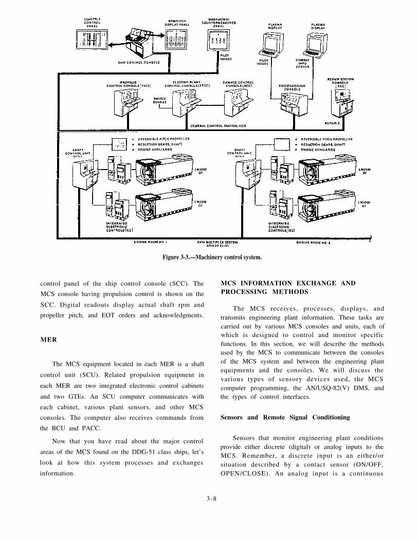
Figure 3-3.—Machinery control system.
control panel of the ship control console (SCC). The
MCS console having propulsion control is shown on the
SCC. Digital readouts display actual shaft rpm and
propeller pitch, and EOT orders and acknowledgments.
MER
The MCS equipment located in each MER is a shaft
control unit (SCU). Related propulsion equipment in
each MER are two integrated electronic control cabinets
and two GTEs. An SCU computer communicates with
each cabinet, various plant sensors, and other MCS
consoles. The computer also receives commands from
the BCU and PACC.
Now that you have read about the major control
areas of the MCS found on the DDG-51 class ships, let’s
look at how this system processes and exchanges
information.
MCS INFORMATION EXCHANGE ANDPROCESSING METHODS
The MCS receives, processes, displays, andtransmits engineering plant information. These tasks arecarried out by various MCS consoles and units, each ofwhich is designed to control and monitor specificfunctions. In this section, we will describe the methodsused by the MCS to communicate between the consolesof the MCS system and between the engineering plantequipments and the consoles. We will discuss thevarious types of sensory devices used, the MCScomputer programming, the AN/USQ-82(V) DMS, andthe types of control interfaces.
Sensors and Remote Signal Conditioning
Sensors that monitor engineering plant conditionsprovide either discrete (digital) or analog inputs to theMCS. Remember, a discrete input is an either/orsituation described by a contact sensor (ON/OFF,OPEN/CLOSE). An analog input is a continuous
3-8

measure of a parameter that may vary over a period oftime (speed in rpms, temperature in degrees). Thefollowing types of sensors are used on the DDG-51 classships:
1. Contact sensors
2. Tank level sensors
3. Temperature sensors
4. Pressure sensors
5. Tachometer/frequency sensors
6. Ship’s service electrical distribution sensors
Signal conditioners external to the MCS provide thecontrol and monitoring interface between a GTE and theSCU, and between a SSGTG and the EPCC. Signalconditioners on the bottom of the GTE provide analoginputs to an interim integrated electronic control (IIEC).The IIEC processes and conditions the GTE parameterinputs to the SCU in its MER. The IIEC analog outputsrange from 0 to 10 volts dc. The IIEC discrete outputsare either 0 volts dc or +10 volts dc.
Signal conditioners in the SSGTG local controlpanel (LOCOP) provide analog inputs to a micro-processor inside the LOCOP. The LOCOP processesand conditions SSGTG inputs and provides a set ofoutputs to the EPCC. The LOCOP analog outputs rangefrom 4 to +20 milliamps. The LOCOP discrete outputsare microprocessor-controlled relay contact statechanges (open/close).
Serial and Parallel Data Communication
Interconsole and intraconsole information ex-changes are in the form of binary signals. These signalsare discrete signals, characterized by high and lowvoltage levels. These voltage levels represent conditionssuch as on/off, opened/closed, or digitized analog data.The signals are arranged in groups or arrays known asdata words. Each binary signal within the data word iscalled a data bit and has a binary zero or a binary onelogic value. The number of data bits contained in a dataword is called the word bit length. The data words canbe exchanged in a parallel or a serial format. Data is sentand received by the same methods we described for theDD-963 and CG-47 class ships.
DMS
The AN/USQ-82F(V) DMS is a dedicated signalprocessing and high-speed serial data transmissionsystem. It is composed of interconnected data flow
control and monitoring units. A dual-stage DMSconfiguration is used on the DDG-51 class ship. Theterm dual-stage indicates that multiplexing occurs intwo stages. The first stage is done in the remotemultiplexer, while the second stage is done in the areamultiplexer. The DMS converts signals suited tomachinery monitoring and control to signal types bestsuited to high-speed communications.
MCS COMPUTER PROGRAMFUNCTIONS
Each MCS console computer on a DDG-51 classship is programmed with common and specificfunctions. The common functions are the general MCSconsole and the EOOW/LU operating functions. Thespecific functions relate to the control and monitoringof the engineering plant equipment assigned to a specificconsole. In this section, we will discuss briefly themethods used by the MCS and the GSEs to test theengineering control system. For a more detaileddescription of the test and calibration proceduresrequired to maintain the MCS equipment, refer to theappropriate technical manuals.
Self-Test Program
The self-test function provides testing of majorcomponents in a console during unit initialization, aftera system reset, and about twice each second duringnormal operation. The self-test function carries out thecomputer and peripheral automatic tests. The test resultsare placed in the console computer database for displayon the PDU when requested by the GSE.
Test Functions
The self- test funct ions at each console aresummarized in table 3-1.
Table 3-1.—MCS Console Self-Tests
3-9

Let’s take a brief look at each of these self-tests andhow they work.
AN/UYK-44(V) TESTS.— The AN/UYK-44(V)built-in test (BIT) determines the operational status ofthe central processor, I/O controller, I/O channeladapters, and main memory. If an error is detected, anAN/UYK-44 BIT ERROR alarm will be displayed onthe PDU. When the computer BIT cannot be completedin the time allotted, an AN/UYK BIT NOT CMPLT
message is displayed on the PDU.
PANEL DISTRIBUTOR TESTS.— The paneldistributor self-tests check the contents of its two RAMsand the console front panel push-button switch positionmessages for proper format. The SCU and DCC eachhave one panel distributor, while the PACC has two. APACC panel distributor supports the controls andindicators associated the SCU. If the RAM does notconform to a predetermined format, an error message isdisplayed on the PDU.
I/O MULTIPLEXER TESTS.— The I/O multi-plexer self-tests check that all inputs and outputs arevalid. In addition, the computer tests all analog inputs todetermine if they are within their permissible range. Thecomputer generates test signals that are sent directlyfrom an output multiplexer to its respective inputmultiplexer. If a computer-generated signal is received
out of limits, an error message is displayed on the PDU.
The computer also tests actual analog signal inputsfrom the engineering plant to determine if they arewithin 7 percent of their full-scale range. For example,an analog input of 10.7 volts dc or greater, with afrill-scale range of 0 to 10 volts dc, is out of range. Whenthis condition is detected, an error message is displayedon the PDU.
AVAILABILITY TESTS.— The availabilityself-test ensures that MCS computer communicationwith a peripheral, through a I/O channel assembly, isuninterrupted. If communications with a specificperipheral are interrupted, an alarm is displayed on thePDU.
CONSOLE STATUS TESTS.— The console statustests are not initiated by the computer self-test function.The computer receives the console status inputs, in theform of contact closure, through a panel distributor, I/Omultiplexer, or RS-232C channel. If a contact closes toindicate a console hardware fault, an alarm will appearon the PDU. A power supply alarm will also be shownon the plasma display unit if a console power supplyfault occurs.
MANUAL TESTS.— A manual testis started by theconsole operator. The operator depresses either theLAMP TEST pushbutton or AUDIBLE ALARM TESTpush button. The LAMP TEST operates the MCSconsole LED driver circuits only and does not test thecomputer program function that controls the indicators.The AUDIBLE ALARM TEST push button operates thealarm annunciator printed on the push button (SIREN,HORN, BELL, or BUZZER).
You have just read about engineering plantmonitoring and control systems for the DD-963,DD-993, CG-47, FFG-7, and DDG-51 class ships. In thefollowing section, we will focus on the CCS operationson these ships.
CENTRAL CONTROL STATIONOPERATIONS
The CCS is the main operating station from whichthe engineering plant can be controlled and monitored.On the DD-963, DDG-993, and CG-47 class ships, thePACC, EPCC, FSCC, and DCC are located in the CCS.On the DDG-51 class ships, the PACC, EPCC,EOOW/LU, and DCC are located in the CCS. On theFFG-7 class ships, the PCC, EPCC, ACC, and DCC arelocated in the CCS. In the remainder of this chapter, wewill briefly discuss some basic operations performedfrom the major consoles located in the CCS of gasturbine-powered ships. First, we will discuss theoperations of the consoles located in the CCS of theDD-963, DDG-993, and CG-47 class ships, followed bya discussion of the consoles on the DDG-51 class ships.Finally, we will discuss console operations from theCCS on the FFG-7 class ships. Refer to the EOSS, theEOP, and the appropriate technical manuals for adetailed description of console operating procedures.
DD-963, DDG-993, AND CG-47 CLASSCCS OPERATIONS
On the DD-963, DDG-993, and CG-47 class ships,the CCS is located remotely from the machinery spaces.This configuration allows for monitoring and control ofthe engineering plant with a minimum of personnel. Thetwo major consoles of the engineering plant on theseclasses of ships are the PACC and the EPCC. The PACCis the console in the ECSS where control of thepropulsion plant and auxiliary systems is normallylocated. The EPCC is the console where control of theelectric plant is normally located. On the CG-47 classships, the EPCC also controls and monitors thedistribution of the ship’s 400-Hz power. We will briefly
3-10

discuss the operation of the PACC and EPCC in thefollowing paragraphs.
PACC
The propulsion plant control systems monitor andcontrol the performance and operation of the equipmentof the main propulsion systems. The operation of thisequipment is controlled from the PACC. The remotelyproduced commands from the PACC operate controlseither to sequence the operation of the main propulsionequipment or to control subsystem operation.
The PACC contains the electronic equipmentcapable of controlling and monitoring both propulsionplants and most of the ship’s auxiliary systems. Figure3-4 shows that each panel of the PACC is dedicated toparticular types of control and monitoring. In thissection, we will briefly discuss the following controlsystems that are operated from the PACC:
1. Fuel oil service system
2.
3.
4.
5.
6.
7.
8.
Lube oil system
Air system
GTE control
EOT control
Throttle and pitch
Plant mode
Auxiliaries
Refer to the EOSS, the EOP, and technical manuals fora detailed description of the operation of these systems.
Fuel Oil Service System
The fuel oil service system control and monitoringfunctions available at the PACC can be divided into twomajor categories: (1) fuel oil service control andmonitoring, and (2) gas turbine module fuel oil controland monitoring. Together they function to deliver fuel
Figure 3-4.—PACC layout.
3-11

oil at the proper pressure and temperature to theindividual propulsion gas turbines.
The following fuel oil service system control andmonitoring functions are available at the PACC:
1.
2.
3.
4.
5.
6.
7.
8.
9.
Fuel oi l service tanks A/B temperaturemonitoring
Fuel oil service tank suction and recirculatingvalves control and monitoring
Fuel oil service booster pump A and B controland monitoring
Prefi l ter different ial pressure monitoring(CG-47 class only)
Header pressure and temperature monitoring
Heater temperature monitoring
Coalescer filter monitoring
Leak detection tank monitoring
Suction strainer differential pressure monitoring
Monitoring functions are available at the PACC andthe PLCC continuously, but control is available only at
one console at a time.
PACC control of the fuel oil service system consists
o f r emo te manua l con t ro l o f t he suc t i on andrecirculating valves associated with the two servicetanks. The PACC also has automatic or remote manualcontrol of the two fuel oil service pumps.
Valve control consists of open and close commandsto the valve motor controllers. Commands are appliedsimultaneously to the suction and recirculating valves.Both valves associated with a service tank must be inthe same state (open or closed) for proper operation.Separate control switches are provided to allow eachservice tank to be operated independently. Service tankmonitoring consists of tank temperature high and lowalarms.
The two service pumps can operate in manual orautomatic control mode. When the pump mode switchis set to MANUAL, the operator can use the pushbuttons on the PACC to control the two pumpsindividually. Setting the pump mode switch to either ALEAD or B LEAD position sets up the automatic controlcircuits to select a lead pump and a standby pump. Pump
control is then a function of header pressure and time.
The following GTE fuel oil control and monitoringfunctions are available at the PACC:
1. Supply temperature monitoring
2.
3.
4.
5.
Fuel purge control
Fuel falter monitoring
Main fuel valves control and monitoring
Emergency trip fuel valve control
GTE fuel oil controls available at the PACC pertainprimarily to controlling the GTE fuel shutdown valvesand emergency trip valves. Controls are also providedfor fuel purging operations. Closure of either of the twomain fuel valves prevents fuel flow to the engine fuelmanifold. Control of these valves depends on the GTEcontrol mode: manual, manual initiate, and auto initiate.
In the manual control mode, the main fuel valvecontrol signals to the free standing electronic enclosure(FSEE) are generated by the push-button indicator onthe PACC. In the manual initiate and auto initiate controlmodes, the fuel valve control signals are automaticallygenerated by the start/stop sequence control logic.
The remaining GTE fuel oil controls available at thePACC are related to fuel purging operations. If an enginehas been shut down for 15 days or longer, it may haveto be purged before starting. Purging is accomplishedby motoring the GTE with the fuel purge valve open.Depressing the FUEL PURGE ON push button at thePACC opens the purge valve and allows fuel oil to flowthrough the engine fuel lines and into the leak detectiontank. The purge valve can be opened only when theoperator depresses the push button on either the PACCor PLCC.
Lube Oil System
Each MER has its own separate and independentlube oil system that can be controlled and monitoredfrom the PACC. Monitoring is available continuously atboth consoles, but control is available at only one of theconsoles at a time. Lube oil control available at thePACC consists of manual and automatic control of thetwo lube oil service pumps. These pumps function toaugment the MRG attached lube oil pump.
If the pump controls at the PACC are to be enabled,the control location switch on the local controllers of thepumps must be in the REMOTE position. Manualcontrol of the two pumps is individually accomplishedwith three push-button indicators. Setting the pumpmode auto/manual logic switch to MANUAL allowsoperator control of pump speed. The push-buttonindicator causes the associated command to be relayedto the PLCC circuitry and then to the pump motorcontroller. Setting the pump mode switch to either theA LEAD or B LEAD position sets up the automatic
3-12

control circuits to select a lead pump and a standbypump. Pump control is then a function of lube oil headerpressure and time.
Lube oil pump control is transferred to the PACCby depressing the control transfer switch at the PLCC.The PACC commands are sent over the serial data busto the PLCC. The PLCC pump control circuitry thenini t iates the proper s ignals to the pump motorcontrollers.
Air System
There are two main air systems associated with theGTEs and the GTGSs: (1) the bleed air system and (2)the high-pressure air system. The bleed air system andhigh-pressure air system are interconnected by pipingand valves. These systems are monitored and controlledat the PACC. Control is available continuous y andsimultaneously at both the PACC and the PLCC.
BLEED AIR SYSTEM.— We will look at the bleedair system in terms of its four distinct subsystems:
1. Starter air
2. Masker air
3. Prairie air
4. Anti-icing air
Located in each bleed air line for each GTE is amotor-operated bleed air valve. The position of the GTEbleed air valve can be controlled manually at the PACCas long as GTE control is transferred to the PACC. Thisvalve can be controlled automatically by the start/stopsequence logic circuits. There are status indicator lightson the PACC that show the position of the bleed airvalves.
The GTGS No. 3 has a bleed air isolate valve thatcan isolate the GTGS No. 3 bleed air from the rest of theship’s system. The ISOLATE push button, located onthe PACC, is illuminated when the valve is closed andNo. 3 GTG is isolated. On the CG-47 class ship, theGTGS solenoid-operated bleed air valves can becontrolled from a bleed air valve control panel in CCS.
Starter Air System.— The starter air system hasthree operating modes available at the PACC: (1)normal, (2) emergency, and (3) motor.
Normal start air is used during a normal startsequence. The start air for the GTE is controlled by themotor air regulator valve. This valve is controllable atthe PACC and provides one of two functions: valveopened nonregulated (start position) and valve opened
regulated at 22 psig (motoring position). The last valvein the GTE start air flow is the starter air valve. Thisvalve is controlled either manually or automatically atthe PACC, if GTE control is transferred to the PACC.The last valve in the GTGS start air flow is the starterair valve that is controlled by the GTGS’s system.
Emergency start air is started by depressing theEMERGENCY push button on the PACC. This actioncauses air from the high-pressure storage flasks to beavailable for GTE starts. The high-pressure air isreduced and enters the GTE start air system upstream ofthe motor air regulator valve.
Masker Air System.— The masker air system causesthe start air system valves to line up to one of twopossible states depending on whether masker air is onor off and if the air system is in automatic control mode.For the first condition (masker air on) after a startsequence, the start air system valves will automaticallyalign to allow masker air to the masker air belts. For thesecond condition (masker air off) after a start sequence,the masker transfer valve will remain in the startposition. Both valve alignments can be performedmanually from the PACC.
Prairie Air System.— The prairie air system controlsconsist of a prairie air supply valve. The PACC controloperates prairie air in both engine rooms from oneON/OFF push-button indicator. If one of the prairie airsupply valves fails to respond to a command, the failureis shown by a lack of illumination of both sections ofthe indicator push button.
Anti-icing Air System.— The anti-icing systemincludes a bleed air injection system and an electricalintake heater system. The bleed air injection system isused to increase the intake combustion air temperaturefor the GTEs and GTGSs. The electrical heater systemis used to prevent ice formation on the stack intakelouvers and blow-in doors. The intake heater controllersmust be in the ON position for the PACC push buttonsto operate the heaters.
The bleed air injection system anti-icing systemmonitoring is available at the PACC for each GTE andGTGS. The injection of bleed air is manually controlledby operating personnel.
HIGH-PRESSURE AIR SYSTEM.— The high-pressure (HP) compressed air system provides HP air tothe weapons systems, aviation equipment, gas turbinestarting, and backup for the ship’s service air system.This system consists of two vertical reciprocating aircompressors, various storage flasks, two dehydrators,and a piping distribution system.
3-13

GTE Control System
Most of the GTE control and monitoring circuitryfunctions primarily for normal start-up and shutdown ofthe propulsion gas turbines. All four GTE control andmonitoring functions can be accomplished at the PACC.There are three possible start/stop modes for each GTEat the PACC: (1) manual, (2) manual initiate, and (3)auto initiate. The auto initiate mode will be discussed inthe plant mode control section of this chapter.
The manual control mode consists of operatorgeneration of the start or stop commands at every stepof the sequence. The operator must make sure each stepis accomplished at the proper time. Sequencing of thesemanual controls is the same as the time sequential flowcharts found in the technical manual.
The manual initiate mode consists of starting andstopping the GTM in a semiautomatic mode. In thismode, the engine wil l s tar t up or shut downautomatically. The control electronics at the PLCC willautomatically sequence the start-up and shutdown stepsrequired. This mode is semiautomatic because the brakeand clutch (brake only on the CG-47 class ships)operation must be done manually.
EOT Control System
The ECSS uses the following three types of EOTsfor propulsion command information:
1. Standard order EOT - Consists of standardengine commands, such as 2/3 back, 1/3 back, stop, 1/3ahead, and 2/3 ahead
2. Digitized EOT - Provides rpm commands of 0to 200 rpm in 1-rpm increments and pitch commands of
–50 percent to +100 percent in 1 percent increments
3. Plant mode EOT - Provides commands ofsecured, split plant, and full power
All three EOTs are at the SCC and PACC. All threeEOTs communicate via the command and control serialdata bus.
STANDARD.— The standard orders are initiated atthe SCC by moving the integrated throttle control (ITC)lever to the commanded standard order position anddepressing the standard order ALERT pushbutton. Thisaction sends the order to the PACC and PLCC for thatparticular shaft. If the PACC has control, the operatorcan acknowledge the order by using either one of twoprocedures. The first is by pushing the STD ORDERswitch indicator, which silences the EOT bell, and then
moving the ITC to match the command from the bridgedisplayed by the ITC flashing indicator. This action willcause the indicator to illuminate steadily. The PACCoperator can also acknowledge the order by moving theITC lever to the new indicated command. This willsilence the bell and illuminate the indicator steadily.
DIGITIZED.— The digitized EOT provides forcommunication of nonstandard orders for pitch andrpm. A nonstandard order is a command for a specifiedpitch or rpm that is outside the predetermined settings.If the PACC has throttle control, the operator can set thethumbwheel switches to make the SET and ORDEREDdigital indicators agree. The operator then moves theITC to the ordered position.
PLANT MODE.— The plant mode EOT consists ofthree possible orders: (1) secure, (2) split plant, and (3)full power. When plant mode is activated, the signal issent to the PACC and flashes the indicator for the givenorder and sounds the bell. The operator acknowledgesthe order by depressing the flashing indicator. When thenew plant condition is achieved, the indicator willilluminate steadily.
Throttle and Pitch Control System
The throttle and pitch control system providescontrol of shaft speed and propeller pitch. This controlsystem is an analog control system that usescontinuously variable signals to control shaft speed andpropeller pitch.
ECSS throttle and pitch control is available at thePLCC, PACC, and SCC. Manual throttle and pitchcontrol is available at the PLCC and PACC. Automaticor integrated throttle and pitch control (ITC) is availableat the PACC and SCC. The PACC ITC levers, one foreach shaft, allow single lever automatic scheduledcontrol of throttle and pitch. Figure 3-5 shows an overallcontrol block diagram of the throttle and pitch controlsystem.
Plant Mode Control System
The plant mode control electronics is located in thePACC. The control works with the start/stop logic at thePLCC. Auto initiate mode is a part of the plant modecontrol logics. In plant mode control, the operator canstart up or shut down main engines in both engine roomswithout using the individual GTE start/stop controls.The plant mode control is normally used only when allof the following systems are in AUTO:
1. GTE start/stop control
3-14

Figure 3-5.—Throttle and pitch control block diagram.
2. Throttle
3. Brake
4. Air
With these systems in auto and the propulsion plantin one of three propulsion configurations (secure, splitplant, or full power), plant mode control is enabled. Withplant mode control enabled, the following modechanges can be performed at the PACC:
1. Secure to split plant (CG-47 class only)
2. Split plant to full power
3. Full power to split plant
4. Full power or split plant to secure
5. Change engine
Auxiliaries Systems
There are certain engineering plant auxiliaries thatcan be monitored and controlled by the ECSS, and thereare others that can only be monitored. The following listcontains the auxiliaries that can be either controlled ormonitored at the PACC:
1. Waste heat boiler (WHB) (monitored)
2. Seawater service (controlled and monitored)
3. Freshwater service (controlled and monitored)
4.
5.
6.
7.
8.
9.
10.
Refrigeration plant (monitored)
Sewage and waste system (monitored)
Distilling plant (monitored)
Air-conditioning plant (monitored)
High-pressure air system (monitored)
Ship’s service air system (monitored)
Chilled water expansion tank system (CG-47class only) (monitored)
11. Combat dry air system (CG-47 class only)(monitored)
12. AEGIS pump system (CG-47 class only)(monitored)
For additional information on these systems, werecommend you consult the propulsion plant manual foreach particular class of ship.
Now that you have read about the control systemsat the PACC, let’s look at those at the EPCC.
EPCC
The electric plant control systems monitor andcontrol the performance and operation of equipmentassociated with the ship’s electrical systems. Theremotely produced commands operate controls to
3-15

sequence the operation of equipment or to control sub-system operation. The operation of the electricaldistribution systems equipment is normally controlledfrom the EPCC.
The EPCC contains the controls and indicators thatare used to remotely operate and monitor the ship’sservice power generation and distribution systems.Figure 3-6 shows that each panel of the EPCC isdedicated to particular types of control and monitoring,based on the class of ship. (See views A and B.) Noticein view B that the EPCC on the CG-47 class ships hasan additional section for the 400-Hz system. In thissection, we will take a look at the following controlsystems:
1 .
2 .
3 .
4 .
5.
6.
7 .
8 .
GTGS monitoring
Electrical distribution system monitoring
Circuit breaker control
Gas turbine control
Generator control
System configurations
Load shedding
TOPS
9. 400-HZ power system
We will briefly discuss these control systems. For adetailed description of the operation of these systems,we recommend you refer to the EOSS, the EOP, and theappropriate technical manuals.
GTGS Monitoring
Each GTGS has sensors to provide remotemonitoring of the gas turbine engine and the generator.The sensor information is sent to the EPCC in one of thethree following ways:
1.
2.
3.
Directly from alarm contact switches
Through alarm detector circuits in the generatorcontrol panel
Through the PAMISE via the S/CE No. 1
The PAMISE provides the high vibration alarm andparameter information for the demand display indicator(DDI).
There are several GTGS alarms at the EPCC thatindicate abnormal conditions to the operator. With twoexceptions, these alarms are initiated by contact sensorsat the GTGS. The alarms that are not initiated by contact
Figure 3-6.—EPCC layout.
3-16

sensors at the GTGS are the high vibration alarm andthe high turbine inlet temperature (TIT) alarm. The highvibration alarm is generated by an alarm detector inS/CE No. 1. The high TIT alarm is initiated by a TIThigh relay in the gas turbine generator control panel. Inaddition to the alarm lights, there are status lights at theEPCC for each GTGS.
Electrical Distribution System Monitoring
The generator status panel at the EPCC providesmeter displays and alarms for monitoring the output ofthe GTGSs. An additional section of this panel is forshore power monitoring. The electrical distributionsystem provides monitoring by using meter displays andalarm lights. The operator can test the conditions ofshore power by using the phase sequence meter and itsassociated switch.
Circuit Breaker Control
The EPCC provides central ized control andmonitoring of the generator circuit breakers, bus tiebreakers, and load center breakers. The push-buttonindicators used to operate these breakers are located onthe EPCC mimic panel. Control of circuit breakers fromthe EPCC is enabled only when the generator controlswitches at the switchboards are in the REMOTEposition.
Circuit breaker control at the EPCC can be dividedinto two categories: operator initiated and logicinitiated. Operator initiated circuit breaker control isprovided at the mimic panel with the push-button switchindicators. Logic initiated circuit breaker “Close”commands originate when the EPCC is in the automaticoperating mode. Bus tie breakers 3S-1S and 3S-2S arethe only breakers with “Auto Trip” commands. Thecommands isolate switchboard No. 3 if all threegenerators are in parallel for more than 2 minutes.
Gas Turbine Control
Gas turbine control available at the EPCC consistsof gas turbine start and stop control and gas turbinefrequency control.
Manual GTGS control available at the EPCCconsists of a START push button, a STOP push button,and a HP AIR/LP AIR GTRB start mode selector switch.The start controls are enabled only when the controltransfer switch at the generator control panel andswitchboard are in the REMOTE position. The operator
initiates a start by selecting the type of air (HP or LP) tobe used and depressing the START push button.
The EPCC STOP pushbutton is not affected by thecontrol transfer switches. When depressed, a signal issent to the turbine stop relay at the switchboard. The stoprelay sends a stop signal to the generator control panelto initiate a normal stop.
Frequency of each GTGS is controlled by anelectronic governor. The electronic governor senses thefrequency of the permanent magnet alternator (PMA)and sends signals to a hydraulic actuator on the gasturbine. The actuator adjusts the fuel flow in the engineto maintain engine speed. Frequency adjustment is madeat the EPCC by raising or lowering a motor-drivenpotentiometer. There are two modes of governoroperation: NORMAL and DROOP. The NORMALmode is isochronous or constant frequency. TheDROOP mode is an alternate mode where frequencydecreases with increasing load.
Generator Control
Control of generator field excitation for a GTGS isaccomplished by its voltage regulator. There are twomodes of voltage regulator operation available at EPCC:AUTO and MANUAL. In the AUTO mode, the voltageregulator regulates the generator output voltage to alevel set by a motor-driven reference potentiometer. Inthe MANUAL mode, excitation current from thevoltage regulator is set by a motor-driven rheostatlocated at the switchboard. Voltage adjustment is madeat the EPCC by commanding either the referencepotentiometer motor (AUTO mode) or the manualrheostat motor (MANUAL mode) in the RAISE orLOWER direction. There are two modes for the voltageregulator: NORMAL and DROOP.
System Configurations
The electrical system is designed so two generatorscan supply all electrical loads. The third GTGS can beput on standby and then automatically started andsynchronized to the bus on failure of one or both of theon-line generators. Automatic failure detection andrecovery is available only when the EPCC is in controland in automatic mode, and the electric plant is in astandard parallel or standard split-plant configuration.
STANDARD SPLIT-PLANT CONFIGURA-TIONS.— Standard split-plant operation requires twoon-line generators, but not paralleled. The switchboardbus of the off-line generator is energized through the bustie connection to one of the on-line switchboards. The
3-17

remaining bus ties are not energized. (See fig. 3-7, view
A.) The EPCC configuration status logic can identifyany split-plant configuration by monitoring the open
and close status of the generator and bus tie breakers.
STANDARD PARALLEL-PLANT CONFIGU-R A T I O N S . — In parallel-plant operations, two
generators are on line and paralleled. Additionally, allbus tie breakers are closed to connect the three mainswitchboards in a loop system. Configuration statuslogic at the EPCC identifies the on-line generators forauto recovery logic. (See fig. 3-7, view B.)
N O N S T A N D A R D P L A N T C O N F I G U R A -
Overpower protection will cause load shedding ofpreselected nonvital and semivital loads. If automaticload shedding does not reduce the load sufficiently,additional loads will have to be removed manually.
Load shedding
Load shedding is a process by which loads areremoved from the electrical bus to prevent overloadingof the on-line generators. Load shedding can beaccomplished manually or automatically. On the CG-47class ships, load shedding is completely independent of
T I O N S . — The open loop paral leled generator the TOPS.configurations, as shown in view C of figure 3-7,energize all three switchboards with two generators.These configurations are operator selected or are theresult of a failure. All electrical distribution functionshave these configurations, but automatic recovery
capability is not available.
EMERGENCY CONFIGURATIONS.— Normalplant operation requires two generators in parallel or
split-plant configurations. In an emergency with twogenerators inoperative, one generator must energize the
Manual load shedding can be accomplished bydepressing the LOAD SHED push-button indicator onthe EPCC. This switch transfers +28 volt dc power to aload shed relay.
Automatic load shedding is initiated by anyoverpower sensor circuit in one of the switchboards. Thesensor circuit energizes a self-contained relay whosecontacts are in paral lel with the LOAD SHEDACTIVATED pushbutton at the EPCC. Closure of thesecontacts energizes the same load shedding control relay
three switchboards. (See view D in f ig. 3-7.) as in manual load shedding.
Figure 3-7.—Electric plant configurations.
3-18

When the load shedding control relay is energized,its contacts pick up tripping relays in each mainswitchboard. The tripping relays complete powercircuits to the trip coils unselected main switchboardcircuit breakers. The coils open the circuit breakers toremove load from the line. Additionally, other loads aresimilarly inhibited in load center switchboards byactivation of tripping relays.
TOPS
The TOPS is an automatic protection systemdesigned to prevent the loss of a GTGS due toovertemperature. The TOPS control panel (shown infig. 3-8) receives analog inputs, such as GTGS inlettemperature, rpm, and kilowatt. These signals originatefrom the PAMISE. The control panel also receivesdigital inputs from the EPCC. These signals aregenerator breaker status, bus tie breaker status, andshore power status. The control panel processes thesignals and provides a listing to the display unit. Basedupon the results of the analysis of the data, the controlpanel issues the commands to close the bleed air valvesand/or initiate load shed. The TOPS control panel will
Figure 3-8.—TOPS control panel.
3-19
take whatever action is needed to maintain the vital
electrical load.
400-Hz Power System
The EPCC on the CG-47 class ships can remotely
operate a total of six 60/400-Hz static converters. Only
four converters are used on this class of ship. The
60/400-Hz converters on the DD-963 and DDG-993
class ships cannot be controlled from the EPCC. The
three converter units on these classes of ships each
provide a shutdown signal, a summary temperature high
signal, and a power available signal to the EPCC.
On the CG-47 class ships, the converters may be
controlled from the EPCC only when the CCS IN
CONTROL ind ica to r i s i l l umina t ed . S t a r t i ng ,
paralleling, and stopping the 60/400-Hz converters ispossible from the EPCC. Control and monitoring of
each static converter is provided by the following
controls and indicator lights:
1. 60-HERTZ POWER AVAILABLE - Ship’s
power is available at the converter input breaker.
2. 400-HERTZ POWER AVAILABLE - The
converter is running. Closing of the converter output
breaker is enabled.
3 . B U S T I E E N A B L E - C o n v e r t e r s a r e
synchronized and parallel operation is enabled. Closure
of the bus tie breaker is enabled.
4. SHUTDOWN - The converter is off. An alarm
or the operator has stopped the converter.
5. COOLANT FLOW LOW - Summary alarm for
all three liquid cooling mediums. The flow is low or has
stopped.
6. TEMPERATURE HIGH - Summary of high
temperature shutdown alarms.
7. LOCAL CONTROL - Control of the converterinput and output breakers is at the converter master
control unit.
8. CCS IN CONTROL - Control of the converterinput and output breakers is at the EPCC.
9. CURRENT - A meter that shows the converter
amperage to a maximum of 481 amperes.
Refer to the 60/400-Hz converter technical manual for
a detailed description of the operation of the static
converters.

You have just read about CCS operations onDD-963, DDG-993, and CG-47 class ships. Now let’slook of the CCS operations on the DDG-51 class ships.
DDG-51 CLASS CCS OPERATIONS
The CCS on the DDG-51 class ships is also locatedremotely from the machinery spaces. The CCS is themain operating station from which the engineeringplant, with the exception of the steering system, iscontrolled and monitored. The three major consoles ofthe engineering plant on this class of ship are the PACC,the EPCC, and the EOOW/LU. The PACC can controland monitor all systems and components that interfacewith the SCUs. This equipment includes the propulsionmachinery, propulsion auxiliaries, and independentauxiliaries. The EPCC controls and monitors theSSGTGs and electrical distribution system. Thisincludes restart control and monitoring of the fourair-condi t ioning plants and some fuel servicemonitoring. The EOOW/LU controls and monitors theMCS data logger and bell logger. We will briefly discuss
the operation of these consoles in the followingparagraphs.
PACC
The MCS propulsion plant control equipmentconsists of two SCUs and the PACC. The PACC islocated in the CCS and communicates with the SCUsthrough the DMS. The PACC provides all controls anddisplays necessary to operate MCS equipment in bothengine rooms. It also provides for much of the MCS’sassociated auxiliary and support systems operations.Figure 3-9 shows that each section of the PACC isdedicated to particular types of control and monitoring.Some of the major controls and monitoring systems arediscussed briefly in the following paragraphs.
Fuel Oil Service System
The fuel oil service system is remotely controlledand monitored by the PACC in two parts: (1) fuel oilservice and (2) propulsion fuel. The fuel oil service and
Figure 3-9.—Overall view of PACC.
3-20
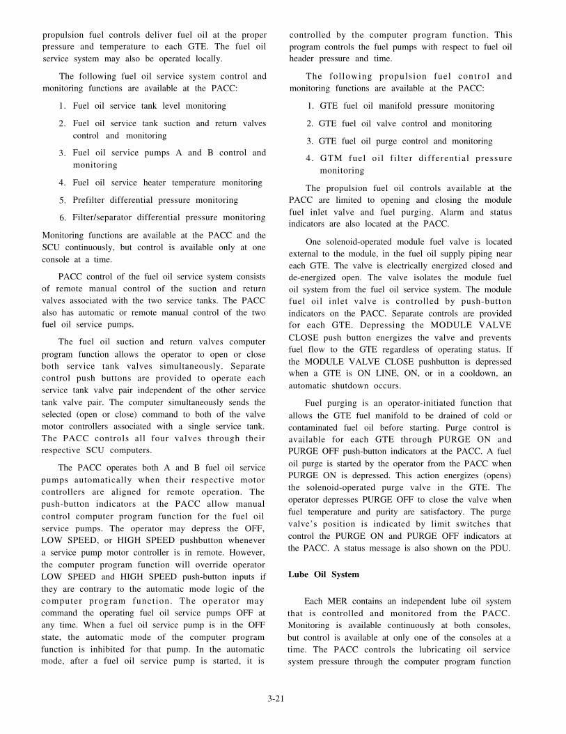
propulsion fuel controls deliver fuel oil at the properpressure and temperature to each GTE. The fuel oilservice system may also be operated locally.
The following fuel oil service system control andmonitoring functions are available at the PACC:
1.
2.
3.
4.
5.
6.
Fuel oil service tank level monitoring
Fuel oil service tank suction and return valvescontrol and monitoring
Fuel oil service pumps A and B control andmonitoring
Fuel oil service heater temperature monitoring
Prefilter differential pressure monitoring
Filter/separator differential pressure monitoring
Monitoring functions are available at the PACC and theSCU continuously, but control is available only at oneconsole at a time.
PACC control of the fuel oil service system consistsof remote manual control of the suction and returnvalves associated with the two service tanks. The PACCalso has automatic or remote manual control of the twofuel oil service pumps.
The fuel oil suction and return valves computerprogram function allows the operator to open or closeboth service tank valves simultaneously. Separatecontrol push buttons are provided to operate eachservice tank valve pair independent of the other servicetank valve pair. The computer simultaneously sends theselected (open or close) command to both of the valvemotor controllers associated with a single service tank.The PACC controls all four valves through theirrespective SCU computers.
The PACC operates both A and B fuel oil servicepumps automatically when their respective motorcontrollers are aligned for remote operation. Thepush-button indicators at the PACC allow manualcontrol computer program function for the fuel oilservice pumps. The operator may depress the OFF,LOW SPEED, or HIGH SPEED pushbutton whenevera service pump motor controller is in remote. However,the computer program function will override operatorLOW SPEED and HIGH SPEED push-button inputs ifthey are contrary to the automatic mode logic of thecomputer program funct ion. The operator maycommand the operating fuel oil service pumps OFF atany time. When a fuel oil service pump is in the OFFstate, the automatic mode of the computer programfunction is inhibited for that pump. In the automaticmode, after a fuel oil service pump is started, it is
controlled by the computer program function. Thisprogram controls the fuel pumps with respect to fuel oilheader pressure and time.
The fol lowing propulsion fuel control andmonitoring functions are available at the PACC:
1. GTE fuel oil manifold pressure monitoring
2. GTE fuel oil valve control and monitoring
3. GTE fuel oil purge control and monitoring
4. GTM fuel oi l f i l ter different ial pressuremonitoring
The propulsion fuel oil controls available at thePACC are limited to opening and closing the modulefuel inlet valve and fuel purging. Alarm and statusindicators are also located at the PACC.
One solenoid-operated module fuel valve is locatedexternal to the module, in the fuel oil supply piping neareach GTE. The valve is electrically energized closed andde-energized open. The valve isolates the module fueloil system from the fuel oil service system. The modulefuel oil inlet valve is controlled by push-buttonindicators on the PACC. Separate controls are providedfor each GTE. Depressing the MODULE VALVECLOSE push button energizes the valve and preventsfuel flow to the GTE regardless of operating status. Ifthe MODULE VALVE CLOSE pushbutton is depressedwhen a GTE is ON LINE, ON, or in a cooldown, anautomatic shutdown occurs.
Fuel purging is an operator-initiated function thatallows the GTE fuel manifold to be drained of cold orcontaminated fuel oil before starting. Purge control isavailable for each GTE through PURGE ON andPURGE OFF push-button indicators at the PACC. A fueloil purge is started by the operator from the PACC whenPURGE ON is depressed. This action energizes (opens)the solenoid-operated purge valve in the GTE. Theoperator depresses PURGE OFF to close the valve whenfuel temperature and purity are satisfactory. The purgevalve’s position is indicated by limit switches thatcontrol the PURGE ON and PURGE OFF indicators atthe PACC. A status message is also shown on the PDU.
Lube Oil System
Each MER contains an independent lube oil systemthat is controlled and monitored from the PACC.Monitoring is available continuously at both consoles,but control is available at only one of the consoles at atime. The PACC controls the lubricating oil servicesystem pressure through the computer program function
3-21

for the lube oil service pumps. Operator commands are
started by push-button indicators in the reduction gearlube oil section of the propulsion mimic panel.
Motor-driven lube oil service pump control signalsfrom the PACC are sent via the DMS to the appropriate
SCU computer. Two modes of motor-driven lube oilservice pump control are available: MANUAL andAUTO LEAD. MANUAL mode allows the operator toselect pump speed with OFF, LOW SPEED, and HIGHSPEED push-button indicators. AUTO LEAD also
allows the operator to select pump speeds manually andtells the SCU computer which pump to start first inresponse to the MRG hydraulically most remote bearingpressure. The control location switch on a lube oilservice pump motor controller must be in REMOTE forthe computer to control pump operation. Manual controlof the lube oil pumps is individually accomplished withthree push-button indicators. Automatic and manual
pump operat ion are enabled when the operatordepresses an AUTO LEAD pushbutton. AUTO LEADprevents the operator from commanding pump speedsthat contradict the lube oil service pump’s automaticmode logic. When pump control is in AUTO LEAD, thepumps cycle as a function of the MRG hydraulically
most remote bearing pressure.
Air System
There are two compressed air systems associatedwith the GTEs and the GTGSs: (1) the bleed air systemand (2) the high-pressure air system. We will look at thebleed air system first.
BLEED AIR SYSTEM.– The bleed air system
contains four distinct subsystems that include thefollowing:
1. Starter air
2. Masker air
3. Prairie air
4. Anti-icing air
The bleed air system is supplied with combustion
air extracted from each operating GTE and SSGTGcompressor. Each GTE and SSGTG has a bleed air valvethat controls the flow of air from the engine to the bleedair header. The bleed air valve for each GTE ismotor-operated and may be controlled from the SCU or
the PACC. The bleed air valve for the SSGTG issolenoid-operated and may be controlled from theSSGTG LOCOP or the EPCC.
Starting Air System.— The starting air system is
supplied by the high-pressure air system through banks
of high-pressure air flasks and the bleed air header. The
bleed air system is the normal source of starting air whengas turbines are operating. The high-pressure air systemflasks are the starting air source when no turbines are
operating or a bleed air PRESS LOW alarm is set.
The operator selects the starting air source at thePACC by depressing the starting air BLEED or HIGH
PRESS push-button indicator. These push buttons
interface with the starting air select computer program
function in the SCU computer. When the BLEED orHIGH PRESS push button is depressed, a status
message appears on the PDU. The BLEED or HIGHPRESS signal is sent with an ON or ON LINE
command, to align the appropriate starting air valve.Valve alignment for a BLEED or HIGH PRESS start is
initiated by the SCU engine state logic-on computer
program function.
A GTE maybe motored with bleed or high-pressure
air using the same air paths as a bleed or high-pressurestart. The only difference is the motor air regulator valveis set to the motor position by the engine state
logic-motor computer program function. The motor air
regulator valve regulates air pressure to 22 psig when in
the motor position. A motor sequence is started when theMOTOR push button at the PACC is depressed for a
GTM in the OFF state.
Masker Air System.– The masker air system is
al igned by the HULL MASKER ON and OFF
push-button indicators at the PACC. These pushbuttons
operate the masker air select computer program functionin the SCU computer. The HULL MASKER ON push
button places the bleed air transfer valve in the masker
position if a GTE start or motor command is not activein the same MER. The HULL MASKER OFF push
button places the bleed air transfer valve in the
start/motor position. The bleed air transfer valve
position is displayed on the PDU.
Prairie Air System.– The prairie air system is
supplied with bleed air through a prairie air cooler and
supply valve in each MER. The PRAIRIE ON and OFFpush-button indicators provide manual inputs to the
SCU computer to issue commands to its connectedprairie air supply valve. When the prairie air supply
valves are operated from the PACC, the appropriate
indicator illuminates and a status message is displayed
on the PDU.
3-22

Anti-icing Air System.– The anti-icing air system issupplied by bleed air injected into the gas turbine intakesupstream of the moisture separator/blow-in panels. Amanua l ly ope ra t ed an t i - i c ing va lve i s l oca t eddownstream of each GTM bleed air regulating valve.The anti-icing valve position is monitored by thecomputer in the SCU, which generates a status messageon the PDU. An ICING alarm indicator for each GTE isprovided on the PACC propulsion mimic panel.
HIGH-PRESSURE AIR SYSTEM.– The HP airsystem provides compressed air at 3000 psig to airstorage flasks of various sizes and special-purposefunctions. The HP air system is supplied by two HP aircompressors. This system is used as an alternate sourceof starting air for the SSGTGs and GTEs. It also suppliesthe 5-inch gun, torpedo tubes, helicopter services, and,if necessary, the ship’s service air system.
GTE Control System
Control and monitoring of all four GTEs is availablefrom the PACC. However, normal control functions areonly available from either the PACC or appropriate SCUat anyone time. The following items of the GTE controlsystem are discussed in this section:
1. Engine fan control
2. Engine state logic
3. Emergency controls
The engine fan control computer program functionis always enabled. It automatically operates the modulecooling fan and damper in response to any one of thefollowing three inputs: (1) GTE cooling air outlettemperature transducer, (2) GTE start command, and (3)the Halon release command. The SCU computercontrols the GTE cooling fan and vent damper.
There are five possible engine states for a GTE.Each engine state is associated with a computer programfunction in the SCU computer. An engine state computerprogram function senses the actual state of the GTE andallows an operator to start an engine state change. Thepush buttons that enable an engine state change are onthe gas turbine propulsion mimic of the PACC and SCU.The five engine state logic computer program functionsare defined as follows:
1. Off - fuel off, power turbine (PT) brake on anddisconnected from programmed control
2. Motor - engine off before alignment of an airsystem for motoring
3. On - engine running at idle, disconnected fromprogrammed control, PT brake on, and stop notcommanded
4. On Line - engine running, connected toprogrammed control, PT brake off, and clutch engaged
5. Cooldown - engine running at idle, disconnectedfrom programmed control, and PT brake on
The SCU computer controls the GTE brakes, valvealignment, cooling fan, and vent damper automaticallyto fulfill any legal engine state change requested by theoperator.
The GTE emergency controls consist of threeseparate, but interrelated, categories: (1) emergencystops, (2) automatic shutdowns, and (3) GTE firedetection and control.
An operator can initiate an emergency stop, while aGTE is in the ON or ON LINE state, by depressing theE M E R S T O P , P R I ( R S V ) H A L O N R L S E , o rMODULE VALVE CLOSE push button. Depressing aHALON RLSE or MODULE VALVE CLOSE pushbutton indirectly causes the SCU to send an emergencystop command to the IIEC. The SCU sends anemergency stop command to the IIEC in response to amodule Halon actuation alarm or loss of GTE fuelmanifold pressure.
An IIEC automatic shutdown is indicated when theAUTO SHUT DOWN lamp on the PACC illuminates.Each automatic shutdown causes the SCU computer tocarry out an emergency stop in addition to the IIECshutdown sequence. There are nine automaticshutdowns associated with the MCS system. GTE lubeoil supply pressure low, power turbine vibration high,and power turbine overspeed shutdown are examples ofautomatic shutdowns. Five of the nine automaticshutdowns are inhibited when BATTLE OVRD ON isdepressed. The five automatic shutdowns inhibited bybattle override are as follows:
1. GTM fail to light off or flameout shutdown
2. GTM lube oil supply-low pressure shutdown
3. GTM power TIT high shutdown
4. GTM gas generator vibration high
5. GTM power turbine vibration high
The GTE fire detection system consists of threeultraviolet flame detectors in the module and a signalconditioner located under the module. When a fire isdetected, an alarm message appears on the PDU and aMODULE FIRE lamp illuminates on the PACC and
3-23

SCU. Halon maybe actuated by depressing the PRI orRSV HALON RLSE push button at the PACC or SCU.After actuat ion of Halon, a HALON SYSTEMACTUATED alarm is displayed on the PDU.
Thrust Control System
The thrust control system consists of throttle/pitchand brake mode control from an MCS control station.This station can be the PACC, SCU, or the BCU.Throttle/pitch control is unified under the programmedcontrol and order di f ference computer programfunctions when NORMAL PROGRAMMED MODE isselected. Throttle and pitch controls are separated, andonly available at the SCU, when LOCKOUT MANUALMODE is selected. Brake mode control is available inboth modes. However, brake engagement requiresadditional operator action when LOCKOUT MANUALis selected. LOCKOUT MANUAL MODE places unitcontrol at the SCU and inhibits control station transfers.
Programmed control is the normal method ofcontrolling ship’s speed. It simultaneously positions thecontrollable pitch propeller (CPP) blades and GTEpower lever angle (PLA) for a propulsion shaft with asingle lever. Two programmed control levers areavailable at the PACC. The port and starboardprogrammed control levers at the PACC may be latchedto ensure the shaf t horsepower is equal . Theprogrammed control levers have a TRIM potentiometerfor fine throttle/pitch adjustments.
The programmed control computer programfunction is designed for fuel economy. To provide thisfuel economy, the programmed control has been dividedinto two operating regions. The first operating region,modulate transmission mode, is used for slower aheadand astern thrust settings. The second operating region,modulate engine mode, is used for faster ahead andastern settings.
Independent Auxiliaries Systems
The independent auxiliaries are systems controlledand/or monitored through an SCU, which do not have adirect impact on the propulsion and propulsion auxiliaryequipment. The seawater cooling system pumps are theonly independent auxiliaries controlled from the PACC.The independent auxiliaries associated with the MCSare as follows:
1. Seawater cooling system
2. Sewage and drainage system
3. Freshwater service
3-24
4.
5.
6.
7.
Air-conditioning/chill water system
High-pressure air system
Ship’s service air system
Internal communication system
Now that you have read about the control systemsavailable at the PACC on the DDG-51 class ships, let’slook at those available at the EPCC.
EPCC
The EPCC provides centralized control of the ship’selectric plant. In the DDG-51 class ships, the EPCCprovides centralized control of the SSGTGs and busdistribution equipment. These features include a panelarrangement of SSGTG controls and display devices inthree groups, one for each generator. Each group alsohas controls and indicators for generator circuit breakeroperation and status. Load shedding, shore powerswitching, and a visual synchronization presentation forall power sources are added features. Limited status ofeach air-conditioning plant status is displayed andrestart controls for each plant are provided. The majorelectrical generation and distribution equipment islocated in auxiliary machinery room (AMR) No. 1,MER No. 2, and the generator room. Each of thesespaces contains one SSGTG and i ts associatedswitchboard.
An integral AN/UYK-44(V) computer provides forcontrol and monitoring of the electric plant. The MCSrequires that the electric plant remain operable if theEPCC computer fails. So, many switch functions arehardwired rather than using the DMS. The wiring isfrom the EPCC to the controlled device in the generatorspaces. The required electric plant sensors are alsohardwired to the EPCC panel indicators to providestatus. An EPCC computer failure causes a loss ofe l ec t r i ca l p l an t a l a rm de tec t ion , EPCC DMScommunications, and any displays at the PDU.
The EPCC contains the controls and indicators thatare used to remotely operate and monitor the ship’sservice power generation and distribution systems.Figure 3-10 shows the locations of the control andindicator panels of the EPCC. In this section, we willbriefly discuss the following control systems operatedfrom the EPCC:
1. SSGTG control and monitoring
2. Electrical distribution monitoring and control
3. Circuit breaker operation

4.
5.
6.
7.
8.
Figure 3-10.—EPCC panel locations.
Gas turbine control
Generator control
Load shedding system operation
Air-conditioning (A/C) plant operation
400-HZ power system operation
Again, refer to the EOSS, the EOP, and technicalmanuals for a detailed description of the operation ofthese systems.
SSGTG Control and Monitoring
Most SSGTG control functions reside in its LOCOPand exciter control panel (EXCOP). The EPCC andswitchboard control stations provide only discreteinputs to the LOCOP and EXCOP. The LOCOPprovides monitoring for the gas turbine and generator,and control for the gas turbine. This includes speedcontrol, which the LOCOP governor uses to regulategenerator output frequency. The EXCOP controlsgenerator output voltage by regulating generator field
excitation. The EXCOP is enabled by the LOCOP when
gas turbine speed exceeds 12,225 rpm.
A SSGTG has sensors to allow remote monitoring
of its gas turbine, generator, and supporting systems.
The EPCC receives sensory information in one of the
following four ways:
1. Directly from controllers or contact switches
2. Directly from temperature or level monitoring
devices
3. Discrete inputs from the SSGTG LOCOP
4. Analog inputs from the SSGTG LOCOP
Inputs to the EPCC are processed by its computer
to determine if an alarm condition exists. Alarms are
indicated on the PDU and by an EPCC control panel
alarm indicator. Eight alarm conditions for each SSGTG
are displayed by specific alarm indicators at the EPCC.
All other alarms are indicated by the appropriate
SSGTG summary alarm light above the PDU.
3-25

There is one SSGTG summary alarm LED for eachSSGTG at the EPCC. The summary alarm lights for
SSGTGs No. 1 and No. 2 operate when at least 1 of 22alarm conditions occurs. The SSGTG No. 3 summaryalarm light operates when at least 1 of 25 alarmconditions occur.
Any inputs to the EPCC not originating from the
SSGTG LOCOP are classified as direct. These directinputs can be either discrete or analog. Direct discreteinputs are typically received from auxiliary contacts inequipment controllers or contact switches associatedwith the SSGTG support system. Direct analog inputs
are received from the resistance temperature elements(RTE) or tank level receivers associated with anSSGTG.
Electrical Distribution Monitoring and Control
An electrical switchboard has analog and discrete
sensing devices for monitoring generator or bus outputand circuit breaker status. Alarm, status, and controlinformation flows between the switchboard and the
EPCC. The EPCC receives this information in one ofthree ways:
1. Directly from potential transformers and current
transformers
2. Directly from circuit breakers
3. As discrete inputs from switchboard relay logic
circuits
The voltage and current signals from the current and
potential transformers are sent to transducers in theEPCC to generate voltage, current, frequency, and
power signals. These signals directly drive the powergeneration and distribution and system output LEDmeters. These signals are also sent to the computer foralarm generation and the PDU’s demand display. Thevoltage displayed on the system output panel meter is
selected by the position of the associated SOURCEselector switch.
The electrical distribution system can be operatedmanually from either the switchboard or the EPCC.
Automatic sequencing takes place in the switchboards
only when a fault condition exists. The EPCC does notautomatically control any circuit breakers as a part ofthe standby generator start or any other function.
Switchboard relay logic and LOCOP sequencer“Generator Breaker Trip Command” are the onlyautomatic breaker controls.
3-26
Shore power breaker control from the EPCC islimited to sending a trip command to each breakersimultaneously when the ALL CB OPEN pushbutton isdepressed. All shore power close control and phasemonitoring devices are local ly operated fromswitchboard No. 2 in MER No. 2. When the shore powerbreakers are closed, circuits in each switchboard willautomatically command each SSGTG governor toDROOP to prepare for a shift from ship’s power to shorepower.
Circuit Breaker Operation
The EPCC provides central ized control andmonitoring of 3 generator circuit breakers, 6 bus tiebreakers, and 12 shore power breakers. The push-buttonindicators for these circuit breakers are located on theEPCC mimic panel. Control of circuit breakers from theEPCC is enabled only when the LOCAL CONTROLalarm light for a switchboard is extinguished.
EPCC operation of circuit breakers is accomplishedthrough the same circuits used by the switchboardcontrols. Depressing an EPCC push-button indicatorenergizes a 28-volt dc close or trip relay at the associateds w i t c h b o a r d . T h e 1 0 - p o s i t i o n s y n c h r o n i z a t i o nCIRCUIT BREAKERS select switch and SYNCMONITOR BYPASS push button enable operation ofthe close circuit. When a relay is energized, a controlcircuit in the breaker assembly energizes a close or opentrip coil to execute the desired status change.
Gas Turbine Control
The gas turbine controls available at the EPCCconsist of gas turbine start air selection, governor modeselection, and manual bleed air valve control. Alsoavailable at the EPCC are gas turbine start and stopcontrol and gas turbine frequency control. Theseoperator interfaces provide discrete inputs to theLOCOP, which operates all SSGTG support systemsand gas turbine control elements.
The availability of an SSGTG start from the EPCCis a function of the LOCOP 301 sequencer “ready tostart” discrete output, LOCOP LOCAL/REMOTEswitch, and switchboard voltage regulator mode switch.When the LOCOP is in REMOTE, the switchboard andEPCC can start the SSGTG. When the switchboardGTG START TRANSFER switch is in LOCAL, boththe EPCC and the switchboard can start the SSGTG.When the switchboard GTG START TRANSFERswitch is in REMOTE, only the EPCC can start theSSGTG.

The manual SSGTG start controls at the EPCC arethe ON, HIGH PRESS, and BLEED pushbuttons. WhenON is depressed, it is combined with the HIGH PRESSor BLEED indication signal in the EPCC input/outputmultiplexer hardware. The start air push buttons provideonly a hardware logic signal within the EPCC and donot cause the start air piping valves to realign.Depending upon which start air indicator is illuminated,the EPCC will send a high-pressure start or bleed airstart signal to the LOCOP.
An SSGTG stop is always available from itsLOCOP, its associated switchboard, and the EPCC. TheEPCC OFF push-button switch sends a signal to theLOCOP, which initiates a normal SSGTG stop andopens the associated generator circuit breaker. AnSSGTG will also automatically stop if certain abnormalconditions occur (slow start, module fire, and so forth).
The output frequency of each SSGTG is controlledby an electronic governor in the LOCOP. The electronicgovernor regulates frequency by adjusting fuel flow tothe gas turbine. When the governor control is at theEPCC, frequency adjustments can only be made fromthe governor mode RAISE/LOWER switch at theEPCC. RAISE increases fuel flow to the gas turbine,while LOWER reduces the fuel flow to the engine.T h e r e a r e t w o m o d e s o f g o v e r n o r o p e r a t i o n :isochronous (ISO) and DROOP. The ISO mode is aconstant frequency mode where fuel flow is regulatedto maintain a constant generator output frequency. TheDROOP mode is a constant fuel flow mode whereincreasing or decreasing the electrical load will causefrequency to decrease or increase, respectively. Themode is selected by depressing either the ISO orDROOP push button at the EPCC. When on shore
power, DROOP is automatically selected by theswitchboard.
Generator Control
Generator field excitation is controlled by one oftwo automatic voltage regulators in the EXCOP.Generator output voltage can be controlled manually orautomatically. One manual mode and two automaticmodes are available at the switchboard and at the EPCC.In the MANUAL mode, excitation current from thevoltage regulator is set by a motor-driven manualvoltage adjust circuit in the EXCOP. The two automaticmodes are differential (DIFF) and DROOP. In thesemodes, the voltage regulator sets the generator outputvoltage to a level determined by the setting of amotor-operated potentiometer in the EXCOP. The DIFFmode is used during parallel operations to allow the
on-line SSGTGs to share the reactive load equally at aselected output voltage. The DROOP mode is used foroperating generators on an isolated bus. It is basicallythe DIFF mode without cross-current compensation.
Load Shedding System Operation
A load shedding operation can be started manuallyor automatically. Manual load shedding is started byoperating the appropriate INIT push-button indicator atthe EPCC or the spring-loaded LOAD SHED switch atthe switchboard. Automatic load shedding is startedwhen an overpower relay in a switchboard or anovercurrent relay on a shore power breaker is energized.
When one overpower relay is energized, its contactsoperate tripping relays in each switchboard. Thetripping relays complete power circuits to the trip coilson selected circuit breakers. When a shore powerovercurrent relay is energized, load shed stage 1 andstage 2 relays in switchboard No. 2 are also energized.These r e l ays comple t e power c i r cu i t s i n t heswitchboards to trip circuit breakers in the load shedsystem. All circuit breakers opened during a load shedoperation must be closed locally. An exception is theair-conditioning plant circuit breakers that can be closedremotely from the EPCC. The tripped circuit breakerscannot be closed until any overpower or overcurrentcondition clears.
Air-Conditioning Plant Operation
The A/C plant normal and alternate supply circuitbreakers can be closed from the EPCC. All four A/Cplants have a remote restart capability to bring a plantthat was operating before a power interruption back online. Each A/C plant can be reconnected to the main busand restarted from the EPCC after a stage 2 load shedor an unexpected power loss.
After a stage 2 load shed, all the primary andalternate sources of power to each A/C plant will havebeen tripped. Depressing the POWER RESTORE pushbutton at the EPCC closes the primary and alternate A/Cplant circuit breakers. All eight breakers will close,regardless of switchboard LOCAL CONTROL alarmstatus, to energize each A/C plant controller.
400-Hz Power System Operation
The 400-Hz power system consis ts of two60/400-Hz static converters that feed separate 400-Hzswitchboards. The EPCC on the DDG-51 class shipsneither controls nor monitors any part of the 400-Hz
3-27

power system. Remote operation of the 400-Hz powersystem is accomplished in combat systems maintenancecentral. The only 400-Hz monitoring done by the MCSis in the interior communication switchboards.
EOOW/LU
The EOOW/LU provides a central location for theengineering officer of the watch (EOOW) to monitor thestatus of the DDG-51 class machinery plants. TheEOOW/LU, shown in f igure 3-11, provides acentralized station for accumulating, processing, anddisplaying the MCS status. Additional functions of theconsole are to provide the data for display on the consoledisplays and on the PDUs on the bridge and in the CIC.The console also provides the means of loading thebubble memories for use by the other MCS consoles.This console is also used to change selected alarmparameters in the software tables of the AN/UYK-44computer memories in the other consoles, to set the dateand time, and to update the shaft revolutions count foruse by other programs. The principal operating unitsfinished with the console are the following:
1. Two PDUs and one keyboard
2.
3.
4.
5.
A bubble memory tape drive unit
A bell log printer
An AN/USH-26(V) s ignal data recorder-reproducer set
An AN/UYK-44(V) computer
Let’s take a brief look at each of these units,
Plasma Display Units
The EOOW/LU panel has two PDUs with a singlekeyboard. The panel CONTROLLED DISPLAY switchconnects the keyboard to the left or right unit. Thekeyboa rd CONTROLLABLE PLASMA/WORK-STATION SELECT key swaps the PDU assignments of“controllable” and “work station.” This arrangement
separates the housekeeping and operational functions.It also eases the PDU casualty operations for the EOOW.The controlled PDU is the automatic alarm and status,and summary group and demand display unit. Manualentry, log tape read, alarm acknowledgement, bubblememory loading, and edit operations are all workstationPDU capabilities.
Figure 3-11.—Overall view of the EOOW/LU.
3-28

Manual entry is a keyboard message input systemallowing up to 32 characters. The message is released toall PDUs in nearly simultaneous fashion. Log tapereading causes data from a tape cartridge to appear onthe PDU. This is useful for reviewing events thatoccurred previously. Both single-entry and tabularmodes are available. The single-entry mode displays thelatest entry and allows scrolling to view older data.Tabular mode displays, up to 25 demand displayselections, are produced for six dates at a particular time.The operator views an individual 25-entry set as a logpage and progresses from page-to-page by using thekeyboard. Editing allows the operator to adjust thecurrent date and time information, alarm parameters,and shaft revolution counter reset data.
Bubble Memory Unit
When the EOOW/LU is f i rs t energized, theconsole’s bubble memory cassettes must be installed inthe drive unit. The computer’s start-up program willcause the console’s operating program software on thecassettes to be loaded into the computer’s memory. Theloading operation will be repeated anytime the computeris rebooted if the cassettes are installed.
Each bubble memory for the MCS has uniqueconsole software programming. A new AN/USH-26master tape cartridge is provide whenever softwarechanges are required. The new cartridge is inserted intape drive 0. Bubble memory cassettes are loaded intothe EOOW/LU bubble memory dr ive uni t . TheEOOW/LU console transcribes the new master tapeprogram to the cassettes. After the cassettes are installedin their MCS console and the console’s initialization andbootstrap procedure is run, the new programs are set inmotion.
Bell Log Printer
The bell log printer is installed in the EOOW/LUconsole front panel. It is a thermal style printer. Theprinting head elements are heated and pressed againstthe heat-sensitive paper. The EOOW/LU computerprogram issues printer control and data print commands.
Signal Data Recorder-Reproducer Set
T h e A N / U S H - 2 6 ( V ) s i g n a l d a t a r e c o r d e r -reproducer set is panel mounted. It is a cartridge tapedrive unit configured for four tape drives. The tapedrives are numbered tape drive 0 through 3; however,only two drives are used because no hardware isinstalled in drives 2 and 3. Drive 0 is a read only drive
and drive 1 is a write only drive. There is a magnetictape driver in the computer program. The driverinterfaces with the set to provide data writing and dataprogram readings. The driver also rewinds the tape andreads the set’s status register.
A tape read or write operation starts when theEOOW/LU computer sends a 16-bit command word tothe AN/USH-26(V). The tape unit performs the actionand follows up with feedback status. The feedback is as ta tus word repor t ing on the command word’soperational success within the tape unit. Feedback statusafter each command operation is issued. When the statusword is error free, the system is assured that satisfactorycommand completion has resulted. Added operationsare entered if a status error exists and may result in alocal tape error alarm.
EOOW/LU Computer
The AN/UYK-44(V), embedded in the EOOW/LU,controls and monitors the MCS by using the DMS. TheAN/UYK-44(V) is a general-purpose, self-containedcomputer. The acronym AN/UYK-44(V) is defined asfollows:
AN - Army/Navy
U - General utility
Y - Data processing
K - Computing
44 - 44th machine designated as AN/UYK
V - Various component groupings available
The computer has a set of hardware modules con-tained in an air-cooled card cage. It also has a coolingfan, control and maintenance panel, and power supplies.The basic modules are standard electronic modules(SEMs), which are buil t to mil i tary standards(MILSTDs). The control and maintenance panel islocated on each console for convenient start-up andmaintenance purposes.
The computer is the principal unit in the interchangeof information for the EOOW/LU. It accomplishes thesetasks with the DMS. Each MCS console has anAN/UYK-44(V) computer that may monitor thepropulsion plant, electric plant, auxiliary machinery,and firemain and hazard detection systems. However,control and alarm input capability varies within theprogram functions assigned to each console computer.The computer enters a bootup process at power turn-on.When required, the computer can also be rebooted from
3-29

the control panel. The operating program is loaded,during the boot process, from bubble memory cassettesinstalled in a tape drive unit within the console. Theprogram is unique to each console housing a computer.
You have just read about CCS operations on theDDG-51 class ships. Now let’s take a look at the FFG-7class ships.
FFG-7 CLASS CCS OPERATIONS
On the FFG-7 class ships, the CCS is the mainoperating station. Most of the engineering plantmachinery can be controlled and monitored from thisstation. The CCS is designed for remote monitoring andcontrol of the engineering plant with a minimum ofpersonnel. The major consoles of the engineering planton this class of ship are the PCC, the EPCC, and theauxiliary control console (ACC). The PCC provides allcontrols and displays needed to operate the GTEs andtheir associated auxiliary and support systems. The
EPCC provides control of the diesel generators and the
electrical distribution equipment. The ACC controls and
monitors 15 auxiliary subsystems. In the following
paragraphs, we will briefly discuss the operation of
these major consoles.
PCC
The PCC, located in the CCS, is the primary
propulsion plant operating station on the FFG-7 classships. The PCC provides all the controls and indications
required to startup and shutdown the propulsion system
and its related auxiliaries. It also provides the controls
and indications to operate the PCS in either the
programmed control mode or remote manual control
mode. The PCC contains signal conditioning, logic,
multiplexing circuits, and the processor for the PCS.Figure 3-12 shows that each section of the PCC is
dedicated to particular types of control and monitoring.
Figure 3-12.—Overall view of the PCC.
3-30

Some of the major controls and monitoring systems arediscussed briefly in the following paragraphs.
Fuel Oil Service System
The fuel oil service system supplies fuel to theGTEs. The control and monitoring function available atthe PCC can be divided into two major categories: fueloil service and gas turbine module fuel oil. Together theyfunction to deliver fuel oil at the proper pressure andtemperature to the individual propulsion GTEs.
FUEL OIL SERVICES.– The following fuel oilservice control and monitoring functions are availableat the PCC:
1. Fuel oil service tank level monitoring
2. Fuel oil service tank suction and return valvescontrol and monitoring
3.
4.
5.
6.
Service pump suction valve monitoring
Service pump control and monitoring
Service pump discharge valve monitoring
F u e l o i l h e a t e r d i s c h a r g e t e m p e r a t u r emonitoring
7. Fuel oil prefilter strainer differential pressuremonitoring
8. Fuel oil filter/separator differential pressuremonitoring
PCC control of the fuel oil service system consistsof remote control of the suction and return valves andautomatic or remote manual control of the fuel oilservice pumps.
The suction and return motor-operated valves areelectrically connected so when the tank suction valve isopened, the return valve also opens. An OPEN/CLOSEalternate-action push button controls the valves from thePCC. The split-legend indicator provides the OPEN orCLOSE status of the valves.
The fuel oil service pump operation can becontrolled at the PCC in either the auto speed advanceor manual mode. The operator selects low speed, highspeed, or stop by depressing the corresponding switchin the manual mode. The pump will advance from lowspeed to high speed if the pressure is below 40 psig andin the auto advance mode. The pump must be manuallyreset to low speed.
The following gas turbine fuel oil controlmonitoring functions are available at the PCC:
and
1. Emergency fuel supply valve monitoring
2. Supply cutoff valve control and monitoring
3. Fuel supply pressure monitoring
The fuel pressure entering the GTE is monitored on
an edgewise meter located on the PCC. The supplycutoff valve control at the PCC is provided by analternate-action switch that is inoperative when locallockout is in effect. The fuel oil supply cutoff valve is a
normally-closed, energized open valve that fails to theclosed position upon loss of power. A split-legendindicator provides the status of the fuel supply cutoff
valve.
The gas turbine emergency supply valve is anormally-open, energized closed valve that fails to theopen position upon loss of electrical power. Asplit-legend indicator provides the status of theemergency fuel supply valve.
Lube Oil System
The reduction gear lubricating oil service system
consists of two main parallel branches, each containinga pump and a relief valve. An air motor drives acoastdown pump that provides lube oil automatically
upon loss of electrical power to both lube oil pumps.
The right most panel on the PCC center section is
the auxiliary panel that provides the control andmonitoring for the MRG lube oil system. The normal
pump assignment signal to the indicator on the PCC
comes from the position of the local transfer switch atthe lube oil service pump control station. The manualoperation requires the operator to start, stop or changespeeds of the normal and standby pumps. The auto speedadvance mode increases the speed of the normal pump,
starts the standby pump, and increases speed of thestandby pump to maintain lube oil pressure. Lube oilpressure is monitored at the most remote bearing for theauto speed advance mode. The auto speed advance
mode has no control features to reduce the speed or stop
either pump. Reducing speed or stopping either pump is
a manual operation, regardless of the position of themode switch.
The PCC propulsion control panel provides a mimiclayout of the MRG with 29 indicators representing the28 gearbox bearings and the one line shaft bearing. All
the bearing temperature alarms are set at 20 degreesabove maximum frill power builder trial data for theindividual ship.
3-31

Air System
There are three main air systems associated with the
start air for the GTEs: (1) the bleed air system, (2) thehigh-pressure air system, and (3) the emergency start airsystem from the start air compressors (SAC). The SACSare driven by the diesel generators.
The bleed air system provides air for the starter,
masker, prairie, and anti-icing air systems. The bleed airsystem can be supplied by either of the running GTEs.An electric motor-operated bleed air valve is located in
each bleed air line inside the module enclosure. Thisvalve is opened and closed with the BLEED AIRVALVE OPEN/CLOSE push-button indicating switchon the PCC. The bleed air lines direct the bleed air toboth the anti-icing system associated with the respectivegas turbine engine and the check valve leading to thebleed air system header.
Each gas generator provides the bleed air for
anti-icing for its associated intake system and intakeplenum. The solenoid-operated bleed air shut-off valveand the motor-operated anti-icing valve have controlalternate-action push-button switches and split-legendindicators on the PCC. The anti-icing system splits intotwo branch lines. One line is for downstream of themoisture separators with a manual valve that is normally
open. The other line is for anti-icing upstream of themoisture separators with an isolation valve that isnormally closed.
GTE Control System
There are three modes that can be selected at thePCC by a t h r ee -pos i t i on sw i t ch : OFF LINE,
MANUAL, and AUTOMATIC. The engine 1A and 1Bstart panels are mirror images of each other. Theyprovide the same controls and indicators presented inthe following four subsystems:
1. Pre-start status
2. Starting systems
3. Engine water-wash group
4. Sequencer mode switch
The off-line auxiliary mode is used for motoring andmaintenance. The fuel and ignition cannot be enabled
simultaneously in the off-line mode. Tests of either theignition or fuel control system without starting the GTE
is accomplished in the off-line mode. An engine waterwash is also accomplished in this mode.
A manual mode of starting the GTE from the PCCis available provided the 18 permissive conditionsrequired are satisfied. The READY TO STARTindicator illuminates when all 18 pre-start permissivec o n d i t i o n s a r e m e t . T h e S T A R T E R O Nmomentary-action push button will begin the manualstarting sequence. The command to the start/stopsequencer located in the FSEE enables the starter to turnthe gas turbine. The start/stop sequencer provides thetime sequence and engine parameters for informationonly. The IGNITION ON and FUEL ON push-buttonswitches on the PCC must be manually operated toprovide the commands.
The automatic (program) mode starts the associatedGTE with automatic timed commands from thestart/stop sequencer in the FSEE. The same permissiveas in a manual start must be satisfied before the enginecan be started. The auto sequence START push buttoninitiates the auto start command to the start/stopsequencer. The start/stop sequencer that initiates theIGNITION ON and FUEL ON commands as acceptableparameters are detected by the FSEE.
Three different methods for securing a GTE areavailable at the PCC. These methods are normal stop,manual stop, and emergency stop. The engine also canbe shut down automatically either during a startsequence or while running by detection of certain faults.
A normal stop can be initiated by the operator ineither the programmed control mode or the manualcontrol mode. The manual stop must be used if controlwas transferred from the local operating panel (LOP) tothe PCC after starting the engine. A normal stop isi n i t i a t ed by dep re s s ing t he NORMAL STOPalternate-action push-button switch. A normal stop canbe aborted at any time before the automatic fuelshutdown valve closes by advancing the gas generatorspeed above idle.
A manual stop is initiated by the operator either in
programmed control mode or in the remote manualcontrol mode. Before a manual stop is initiated, the gasgenerator should be run at idle speed for 5 minutes toallow the engine parts to cool evenly. A manual stop usesthe circuitry in the start/stop sequencer to stop the GTE.The manual stop command, provided by depressing theMANUAL STOP push-button switch, causes bothautomatic fuel shutdown valves to close.
An emergency stop can be initiated by the operatorat any time, in any control mode, and without regard towhich console has GTE control. The EMERGENCYSTOP OVERRIDE switch at the LOP must not be
3-32

enabled to accomplish an emergency stop at the PCC.The emergency stop command causes the circuitry inthe LOP and FSEE to immediately de-energize thePOWER TURBINE OVERSPEED TRIP switch. Thisaction causes both automatic fuel shutdown valves toclose and latch. This will shut down the GTE.
EOT Control System
The EOT control system on the FFG-7 class ship isa standard Navy installation. The EOT provides anelectromechanical communication system between thebridge and the PCC. The EOT on the PCC is located onthe lower or propulsion control panel and providescontinuous position indication. The EOT also providessignals to the discrete multiplexer, which are inputs tothe PCS bell logger program.
The EOT is used to relay standard orders from thebridge to the PCC. When the bridge orders a change ofspeed, one of the pointers in the EOT will point to therequested speed. The PCC operator acknowledges theorder by moving the other pointer to match the bridgepointer. This is done by using the knob below the EOT.
Throttle and Pitch Control System
The throttle and pitch control system providescontrol of shaft speed and propeller pitch. The controlsystem can be operated in three modes: local manualcontrol, remote manual control, and programmedcontrol.
The propulsion control system can be operated inthe manual control mode from the PCC or the LOP. Theprogrammed control mode is the primary mode of oper-ation and is initiated from the PCC or SCC. The relation-ship between the pitch and throttle is automaticallyscheduled by the PCS in the programmed mode.
Now that you have read about the control functionsavailable at the PCC, let’s look at those available at theEPCC.
EPCC
The EPCC contains the controls and indicators thatare used to remotely operate and monitor the ship’sservice power generation, distribution, and relatedsupport systems. As shown in figure 3-13, each panel
Figure 3-13.—EPCC panel locations.
3-33

incorporates a variety of control and monitoringdevices. These devices include: alarm and statusindicators, generator status, mimic and distributioncontrol, and plant system control.
In this section, we will briefly discuss the followingcontrol systems that are operated from the EPCC:
1.
2.
3.
4.
5.
6.
7.
8.
Diesel control and monitoring
Generator monitoring and control
Switchboard and distribution monitoring andcontrol
Shore power monitoring and control
Engine fuel oil service system
Auxiliary fuel oil service system
Jacket water system
Supervisory control system (SCS)
We will provide only a brief discussion of these systems.Again, refer to the EOSS, the EOP, and appropriatetechnical manuals for a more detailed description of theoperation of these systems.
Diesel Control and Monitoring
Each SSDG has sensors to provide remotemonitoring of the diesel engine and generator. Thesensor information can be viewed either on meters orthe DDI. Sensor signals are of two types: analog anddiscrete. Analog signals represent parameters, such asfuel levels, temperature, pressure, or rpm. Discretesignals indicate the occurrence of an event, such as abreaker open, breaker closed, motor running, or motornot running. Commands are control outputs from theEPCC, and some action is expected in response to thissignal.
The EPCC monitors several conditions of the SSDGand displays them in several ways. The EPCC monitorsthe diesel for the following conditions:
Engine fuel tank level, fuel pressure, and returntemperature
SSDG manifold pressure
Diesel fuel temperature
Turbocharger air pressure
SSDG lube oil discharge pressure, temperature,and sump level
Engine speed and exhaust temperature
Alarms on the EPCC are of two types: hardwiredand processor generated. Hardwired alarms comedirectly to the alarm display unit, causing an alarm tosound and an indicator lamp to illuminate. The operatorcan cancel the sound by depressing the ALARMACKNOWLEDGE push button. There are two levels ofaudible alarms at EPCC. The first level is a horn thatsignifies a problem that requires immediate operatoraction to prevent damage or loss of power. The secondlevel is a bell for a problem that needs correction as soonas practical.
The EPCC controls the diesel for both start-up andshutdown. The SSDG can be shut down under normalconditions or in an emergency. Under emergencyconditions, some diesel functions must be reset. Oncethe generator set is running, the EPCC controls whattype of voltage regulation will be used and how thegovernor will control SSDG speed and load. Theprocessor in the EPCC can control the operation of theSSDG when the AUTO mode is selected.
The EPCC operator can start the generator set if theLOCAL/REMOTE switch is ON and al l safetyconditions are met. Starting from the EPCC can be eitherautomatic or manual. As engine speed builds up, a fueloil pressure switch opens and de-energizes a pilotcracking relay. Once the engine is started and enginespeed starts to pickup, the governor will maintain SSDGspeed. Initially the speed is controlled by the mechanicalgovernor until the limit setting is reached. Then asgenerator voltage builds up, the electrical governortakes over control. A 115-volt ac power supply isrequired for the automatic start sequence, although thestart can be accomplished manually.
Under normal conditions, the engine is stopped, bythe operator by pushing the engine STOP push buttonon the local panel or depressing the remote PRIMEMOVER STOP push button on the EPCC. During thisstop sequence, the governor actuator is disconnectedfrom the governor control circuit. Dropping resistorsapply a fixed voltage into the governor actuator, causingit to go to the shutdown mode. As the engine loses speed,the fuel pressure drops and opens a switch thatdeactivates the shutdown condition.
An emergency stop can be initiated by the operatorat the EPCC by depressing the EMERGENCY STOPpush button. This is the same sequence as the normalshutdown except the air intake system is closed off byactivating the engine air box relay. After an emergencystop, the air intake solenoid must be manually reset.Until it is reset, an engine-mounted shutdown lockoutswitch will inhibit the engine from being started.
3-34

Generator Monitoring and Control
The generator section of each SSDG is monitoredfor control and synchronizing. Transducers pick upparameters that need to be monitored and send them upto the EPCC. The parameters are processed by the DDIand the SCS and by alarm circuits and gauges.
Current, voltage, frequency, and power readings areavailable from the EPCC by dialing in the appropriateaddress on the DDI or reading the parameters directlyoff meters on the EPCC. Stator temperature is monitoredfor each phase of the generator. This is the only meteron the EPCC that reads out in degrees centigrade ratherthan degrees Fahrenheit. The status of the voltageregulator and fields exciter is indicated on the EPCC bytwo green lights: one for manual mode and the other forautomatic mode. Two more green lights on the EPCCmonitor the state of the differential or droop selector.
The generator can be controlled through thegovernor system, the voltage regulator, and thesynchronizer. The voltage regulator is used to vary thefield excitation that, in turn, controls the speed of thegenerator.
The governor controls the generator set in twodifferent modes: isochronous and droop. Theisochronous mode is used to share the loading on thegenerators and yet keep a constant speed or frequency.The amount of fuel to the diesel determines the load eachgenerator can carry. In the droop mode, the frequencywill vary as the load is changed, but only withinpredefine limits. This predefine area of droop is O to6 percent of the bus frequency. The frequency of agenerator also can be controlled manually from the frontpanel of the EPCC. The increase/decrease knob willchange the frequency higher or lower, when the operatorneeds to match a generator to a bus to parallel it.
The voltage regulator controls the generator outputthrough the field excitation. The voltage can bemanually controlled from the respective switchboards,except from switchboard No. 4. Switchboard No. 4 is inthe same space as the EPCC and has the manual voltagecontrol on the EPCC panel. The manual presetpotentiometers give the field excitation circuit areference from which to work. The second mode is theAUTOMATIC mode. The voltage regulator AUTOADJUST potentiometer on the EPCC can raise or lowerthe voltage by controlling a motorized potentiometer onthe generator set. The motorized potentiometer sets alimit for field excitation and voltage output. If thevoltage goes up, feedback causes the field excitation todrop, bringing the voltage back into tolerance.
Switchboard and Distribution Monitoring andControl
Power from the generator is monitored, controlled,and distributed through a system of meters, electronics,and circuit breakers. Under automatic operation, theEPCC can perform all three functions through theprocessor software programs.
The circuit breaker status of each SSDG ismonitored for the generator, bus tie, and load shedcircuit breaker position. The EPCC will illuminate astatus indicator if the circuit breaker at the switchboardis different from the switch position at the EPCC. Vitalpower circuit breakers, such as fire pump controls, aremonitored at the EPCC on the vital power feeder circuit
breaker status panel.
The main breakers for the generator set, loadsheddings, and bus ties are monitored on the EPCC.Others, such as the radar room or seawater pump circuitbreakers, are also monitored but not controlled from theEPCC. Other functions that are monitored from theEPCC are power supplies, uninterruptible powersupplies (UPS), and the console heaters. At the EPCC,the total output for the ac generation system is monitoredfor frequency, voltage, and current. Individual bus tiescan be monitored for current loads by selecting each bustie with the rotary switch on the EPCC.
The generator can be taken off the line if REMOTE
control is given to the EPCC and the generator switch isturned to the TRIP position. The switch will work in theCLOSE position only if the paralleling mode switch isin the BYPASS or PERMISSIVE position and thegenerator switch is a t the BUS posi t ion. ThePERMISSIVE mode permits manual closure of thebreaker only when the automatic paralleling device(APD) senses the generator is in synchronization withthe power bus. The BYPASS disables the APD sosynchronization has to be accomplished manually. Thegenerator breaker is closed manually by the operator.
The load shed circuit breaker is opened and trippedby the EPCC operator when the EPCC is in theREMOTE mode. This circuit breaker can be manuallyor automatically tripped. The sensors from the generatorbus will trip all load shed circuit breakers when anoverload condition is sensed. This action will removethe nonvital bus from the bus ring.
As mentioned earlier, the manual voltage control forthe No. 4 switchboard is on the EPCC since theswitchboard and the EPCC are both in the CCS. The No.4 switchboard does not have a remote control mode;
3-35

therefore, there is no LOCAL/REMOTE indicator onthe EPCC for this switchboard.
Shore Power Monitoring and Control
The EPCC operator can monitor the seven breakersconnected to shore power and can use the TRIP lever totrip all seven breakers. current up to 3000 amperes fromthe shore power source can be monitored on a meter atthe EPCC. Each of the seven breakers can handle 400amperes. The status of each breaker is indicated byillumination of its own blue light. The EPCC controlsthe transfer of shore power to ship’s power only. Thetransfer of ship’s power to shore power can only beaccomplished by the 3SA switchboard.
Engine Fuel Service System
The EPCC provides for remote monitoring of theSSDG’s fuel service system. The EPCC indicates withalarms when the fuel tank level is beyond the high levelof 90 percent of tank capacity or drops below the lowlevel of 20 percent of capacity. Engine fuel dischargepressure and manifold pressure are monitored by theEPCC through the SCS. Engine fuel discharge pressureis displayed on edgewise meters on the EPCC frontpanel. To avoid transient alarms, the supervisoryprovides a 16-second delay on the level indicatingalarms.
Auxiliary Fuel Service System
The EPCC controls the suction valves for each ofthe six auxiliary fuel tanks. The EPCC operator cancontrol which tank is used to supply SSDG No. 4 orSSDG No. 1, since they have two tanks. The SSDG No.2 and No. 3 share two day tanks; therefore, the EPCCoperator can only open or close these tanks. The EPCCoperator cannot transfer fuel to the day tanks. Thistransfer is done locally in auxiliary room No. 2.
Jacket Water System
The jacket water system provides cooling water tothe jacket of the diesel engine and acts to cool thelubricating oil. Each engine is served by its own jacketwater system. The water is circulated through eachsystem by a centrifugal pump that is apart of the dieselengine.
Two resistance temperature detectors (RTDs) areprovided in the jacket water outlet line from the dieselengine. One detector provides a signal to the EPCC toprovide continuous display and to actuate a HIGH
TEMPERATURE audible and visual alarm. The seconddetector supplies a signal to an indicator mounted on thediesel engine gauge board. A temperature switch is alsolocated in the diesel engine jacket water outlet piping.The switch energizes a high-temperature alarm on thelocal switchboard.
A pressure transducer, located at the discharge ofthe jacket water pump, provides a signal to the EPCCfor demand display readout. The expansion tanks haveboth a liquid level gauge and a low level alarm. The lowlevel alarm energizes an audible and visual alarm at theEPCC when the level drops to 7 1/2 gallons.
The EPCC controls the flow of seawater to thejacket water system by opening or shutting themotor-operated valve leading from the seawater chest.A dual illuminated indicator on the EPCC monitors theOPEN or SHUT condition of the seawater valve. Thedischarge of seawater, after it has picked up heat fromthe jacket cooler, is routed to the overboard valve. TheEPCC has controls and monitoring associated with thisdischarge.
SCS
This programplant for failureseither condition
module SCS monitors the electricor degradation of performance. Ifoccurs, the SCS either initiates
corrective action or alerts the operator to take correctiveaction. The supervisory control is executed during thea l l o t t e d 5 0 - m i l l i s e c o n d i n t e r v a l o f e v e r y200-millisecond program cycle when the supervisorycontrol mode switch is in the AUTO position. Whenexecuted, this function reads the SHORE POWERindicator, the supervisory control mode, and each SSDGcontrol mode. If the electric plant is on shore power orthe supervisory control mode is off or all SSDGs are inthe local control mode, control is returned to theexecutive control program. Otherwise, the status of eachSSDG is established and a bit pattern is generated toidentify the SSDG status and those SSDGs operating inparallel. Each SSDG status is recorded in a 16-bitcomputer word and updated each program cycle. Referto the appropriate technical manual for a detaileddiscussion on the SCS.
A C C
The ACC, shown in figure 3-14, controls andmonitors 15 auxiliary subsystems and interfaces withthe software program of the EPCC. This interfaceprovides for demand display readout, alarm monitoring,and logging data on the data logger. Controls and
3-36
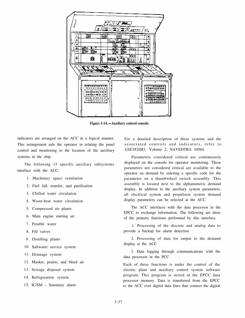
Figure 3-14.—Auxiliary control console.
indicators are arranged on the ACC in a logical manner.
This arrangement aids the operator in relating the panel
control and monitoring to the location of the auxiliary
systems in the ship.
The following 15 specific auxiliary subsystems
interface with the ACC:
1.
2.
3.
4.
5.
6.
7 .
8.
9 .
10.
11.
12.
13.
14.
15.
Machinery space ventilation
Fuel fall, transfer, and purification
Chilled water circulation
Waste-heat water circulation
Compressed air plants
Main engine starting air
Potable water
Fill valves
Distilling plants
Saltwater service system
Drainage system
Masker, prairie, and bleed air
Sewage disposal system
Refrigeration system
IC/SM - Summary alarm
For a detailed description of these systems and thea s s o c i a t e d c o n t r o l s a n d i n d i c a t o r s , r e f e r t oGSE3/GSM3, Volume 2, NAVEDTRA 10564.
Parameters considered critical are continuouslydisplayed on the console for operator monitoring. Thoseparameters not considered critical are available to theoperator on demand by entering a specific code for theparameter on a thumbwheel switch assembly. Thisassembly is located next to the alphanumeric demanddisplay. In addition to the auxiliary system parameters,all electrical system and propulsion system demanddisplay parameters can be selected at the ACC.
The ACC interfaces with the data processor in theEPCC to exchange information. The following are threeof the primary functions performed by this interface.
1. Processing of the discrete and analog data toprovide a backup for alarm detection
2. Processing of data for output to the demanddisplay at the ACC
3. Data logging through communications with thedata processor in the PCC
Each of these functions is under the control of theelectric plant and auxiliary control system softwareprogram. This program is stored in the EPCC dataprocessor memory. Data is transferred from the EPCCto the ACC over digital data lines that connect the digital
3-37

transmitter circuits with the digital receiver circuits inthe ACC. The EPCC output data consist of addressinformation for both input and output data transfers anddigital data that drive the DDIs on the ACC.
ENGINEERING CASUALTY CONTROL
The mission of engineering casualty control is themaintenance of engineering services in a state ofmaximum reliability under all conditions of operation.In regard to the CCS, casualty control includes bothmachinery and electrical casualty control. Efficient CCScasualty control is the result of effective personnelorganization and training. The ability to detect andidentify signs of initial trouble in equipment isdeveloped through familiarization with plant operation.
The details on specific casualties that can occur inthe CCS of a gas turbine-powered ship are beyond thescope of this TRAMAN. Detailed information oncasualty control can be obtained from the engineeringoperational casualty control (EOCC) portion of theEOSS. The EOCC contains important informationship’s personnel can use to recognize casual tysymptoms and determine their probable causes andeffects. The EOCC also contains information on actionsCCS personnel can take to prevent casualties. Itspecifies procedures for controlling single- andmultiple-source casualties. The EOCC manuals area v a i l a b l e a t e a c h w a t c h s t a t i o n i n C C S f o rs e l f - i n d o c t r i n a t i o n . T h e m a n u a l s c o n t a i ndocumentation to assist engineering personnel indeveloping and maintaining maximum proficiency incontrolling casualties to the ship’s propulsion plant.
In the CCS, the speed with which corrective actionscan be applied to an engineering casualty is frequentlyof paramount importance. This is particularly true whencasualties can affect the propulsion power, steering, orelectr ical power generat ion and distr ibut ion. Ifcasualties associated with these functions are allowed tobecome cumulative, they may lead to serious damage tothe engineering plant. When possible risk of permanent
damage exists, the commanding officer has theresponsibility of deciding whether to continue operationof the affected equipment under casualy conditions.
Although speed in controlling a casualty isessential, actions should never be undertaken unlessengineering department personnel have accurateinformation concerning the affected equipment andassociated system. Without accurate information, thecasual ty could be mishandled, in turn causingirreparable damage to the equipment and possible lossof the ship. Speed in the handling of casualties can beachieved only when engineering personnel haveacquired knowledge of the equipment and associatedsystems and have been thoroughly and repeatedlytrained in the routines required to handle specificpredictable casualties.
SUMMARY
This chapter has provided you with a variety ofinformation you will need to become an efficient gasturbine specialist. In this chapter, we discussed thevarious engineering control system operations found onthe gas turbine-powered ships. We described themethods used by these control systems to exchange andprocess the information necessary to control a gasturbine engineering plant. We also described sometesting and calibration procedures for these systems andsome basic operational procedures performed at theconsoles located in the CCS of DD-963, DDG-993,CG-47, DDG-51, and FFG-7 class ships.
A s y o u a d v a n c e i n t h e G S r a t i n g , y o u rresponsibilities for the engineering control system andits operation will increase. The information provided inthis chapter should help you further understand theelectrical and electronic interfaces provided by theengineering control systems. We also referred you toother publications that will give you a more in-depthexplanation of the material covered in this chapter. Youshould study these additional publications to become amore proficient and reliable technician.
3-38

CHAPTER 4
ENGINEERING SUPPORT SYSTEMS MAINTENANCE
As a GSE, you will be tasked primarily with theoperation and maintenance of gas turbine engines. Youalso will be tasked with the maintenance and repair ofsome of the engineering support systems. In this chapterwe will describe some of the maintenance you mayperform on various engineering support systems. Thesesystems include the ship’s service fuel system, the bleedair and start air system, the gas turbine fuel system, themain lube oil system, and the waste heat recoverysystem.
The engineering support systems are an essentialpart of the main propulsion plant. In fact, the plant couldnot operate efficiently without these systems. As a GSE,you will be assigned to perform PMS, repair, andmaintenance on the electrical and electronic parts of thesupport systems. On DD-, CG-, and DDG-class ships,your responsibilities will also include the waste heatboiler (WHB) control panel.
Since the engineering support systems will varyamong ship classes, we will describe these systems ingeneral terms. The examples you will see in this chapterare from various ship classes. Always refer to yourship’s engineering operating procedures (EOP) andengineering operational sequencing system (EOSS) fordetailed information on these systems.
SHIP’S SERVICE FUEL SYSTEM
The ship’s service fuel system is designed tocondition and supply clean fuel to the main engines andthe generators. The fuel is delivered at the propertemperature and pressure for efficient operation of theengineering plant. A ship’s fuel service system usuallyconsists of service tanks, strainers, booster pumps,filter/coalescers, prefilters, and associated piping. As aGSE, you wil l mainly be concerned with themaintenance of the booster pump motors, the boosterpump controllers, and the filter/coalescers.
OPERATION
The ship’s fuel service system on board gas turbineships is normally operated and monitored by theengineering control and surveillance system (ECSS),propulsion control system (PCS), or the machinerycontrol system (MCS). On the DD-963, DDG-993, and
CG-47 class ships, the fuel service system controls andindicators are located on the propulsion and auxiliarycontrol console (PACC) and the propulsion local controlconsole (PLCC). On the FFG-7 class ships, the fuelservice system controls and indicators are located on thepropulsion control console (PCC). On the DDG-51 classships, these controls and indicators are located on thePACC and the shaft control unit (SCU).
The pumps and valves for the fuel service systemare controlled from the control consoles. The controlconsoles provide for stopping and starting of the fuelpumps and opening and closing of the tank valves. Fromthe control consoles, you can place the pumps in slow(low), fast (high), or stop. The operation of the fuelpumps also can be placed in manual or automatic controlfrom the consoles.
COMPONENTS
As mentioned earlier, the ship’s service fuel systemconsists of several parts. In the following sections, wewill discuss only the parts that are of primary concernto the GSE. This discussion wil l include themaintenance and repair of the fuel booster pump motors,fuel booster pump controllers, motor-operated valves,and fuel filter/coalescers. Refer to chapter 5 of thisTRAMAN for a detailed discussion of the maintenanceand troubleshooting procedures associated with motorsand controllers.
Fuel Booster Pump Motors
The motors for the fuel service system are 3-phase,60-hertz (Hz), 440-volt ac, fan-cooled motors. Thesetwo-speed motors are designed for constant-speed andcontinuous-duty operation. On the DDG-51 and FFG-7class ships, the fuel pump motors drive the fuel pumpthrough a reduction gear unit. If you are assigned to aDDG-51 or FFG-7 class ship, you will need to check theoil level in the reduction gear unit periodically.
MAINTENANCE.– You will maintain the ship’sservice fuel booster pump motors the same as you wouldany other motor. This includes keeping the insulationclean and dry, the electrical connections tight, and themotor in good mechanical condition. Usually, you willaccomplish maintenance through PMS. Be sure to keep
4-1

the interior and exterior of the motor clean and free of
dirt. Remember, dirt and debris are the major causes of
motor failure.
TROUBLESHOOTING.— As a GSE, you must
troubleshoot the fuel booster pump motors whenever
malfunctions occur. A fault in the motor is usually
caused by short circuits, open circuits, or grounds. You
must locate and repair these faults to restore the fuel
system to its maximum operating condition. Refer to
chapter 5 for additional information on troubleshooting
the fuel booster pump motors.
Fuel Booster Pump Controllers
On gas turbine-powered ships, the controllers for
the fuel service system are located in the engine rooms.
The controllers operate from a 3-phase, 60-Hz, 440-volt
ac source and provide local control of the fuel booster
pumps. The pumps can be stopped and started from
these controllers. The controllers are usually equipped
with reset push buttons to restore motor overloads.
M A I N T E N A N C E . – The maintenance for the
ship’s service fuel booster pump controllers is the same
as for any other type of electrical controller. On most
gas turbine-powered ships, you, the GSE, will be
responsible for the maintenance of these controllers. On
some ships, however, this task may be the responsibility
of the electrician’s mates (EMs).
In any case, proper preventive maintenance will
reduce the chance of failure in this equipment. Routine
PMS includes keeping the insulation resistance of the
control and power circuits high and making sure the
electrical connections are tight. Any problems you find
in the controllers must be corrected immediately. Make
sure you follow the proper electrical safety precautions
during the maintenance of these controllers.
TROUBLESHOOTING.— During PMS on the fuel
booster pump controllers, you will sometimes find it
necessary to troubleshoot these devices. A fault in the
controller is usually caused by short circuits, open
circuits, or grounds. Since the controller is an
electromechanical device, it will sometimes give in to
mechanical failure. You, the GSE, also must locate and
repair these types of faults to the controller. Refer to
chapter 5 for additional information on troubleshooting
fuel booster pump controllers.
4-2
Motor-Operated Valves
Motor-operated valves allow the console operatorremote control of certain valves in the ship’s service fuelsystem. Motor operators are found on the fuel servicetank suction and recirculating valves and fuel boosterpump suction valves.
Study the motor-operated valve shown in figure 4-1.The motor-operated valve assembly consists of anelectric motor driving a gear drive system that is coupledto a valve. The motor housing contains a torque limiterthat protects the valve and the motor from overloaddamage. Most types of motor-operated valves will alsoinclude a handwheel that permits manual operation ifelectrical malfunction occurs. Motor-operated valves ongas turbine-powered ships are remotely controlled fromthe PCC, PACC, PLCC, and SCU, or locally at the valvecontroller.
MAINTENANCE.— The maintenance on motor-operated valves includes cleaning, inspecting, andtesting. The controller of a motor-operated valve isnothing more than a simple reversing controller. Themaintenance procedures used on motor-operated valvesare the same as those you would use to maintain basicmotors and controllers. On most gas turbine-powered
Figure 4-1.—Fuel service system motor-operated valve.

sh ip s , t he GSEs pe r fo rm the ma in t enance on
motor-operated valves. Depending on the class of ship,
however, this task may be the responsibility of the GSEs
or EMs.
TROUBLESHOOTING.— You can locate the
faults in a motor-operated valve by using the same
troubleshooting procedures we discussed for motors
and controllers. These faults are usually caused by short
circuits, open circuits, or grounds. Since a motor-
operated valve is an electromechanical device, many
problems can be traced to the interface between the
controller and the gear drive system. Mechanical
failures in motor-operated valves are not uncommon.
The GSE is usually called to locate and repair faults in
these components. Refer to chapter 5 for additionalinformation on troubleshooting a motor-operated valve.
Fuel Filter/Coalescers
Fuel filter/coalescers are installed in the ship’s ser-vice fuel system to filter out solid particle contamination
and to coalesce and remove all suspended water. These
units combine the processes of filtration of solids and
separation of immiscible liquids in two successivestages. On the DD-963, DDG-993, and CG-47 class
ships, fuel filter/coalescers have an electrical control
box that controls the automatic shifting of the unit. On
the DD-963 and DDG-993 class ships, the electrical
control box is located behind the instrument panel and
contains the electrical control circuit. (See fig. 4-2,
Figure 4-2.—Fuel oil filter/coalescers.
4-3

view A.) The four indicator lights, the heater switch, andthe changeover switch are mounted through the back ofthe box and protrude through the instrument panel. Onthe CG-47 class ship, the electrical control box is locatedin front of the instrument panel. Notice that the electricalcontrol box in figure 4-2, view B, does not have a heaterswitch.
MAINTENANCE.— The electrical control box forthe filter/coalescers is nothing more than an electricalcontroller. You will maintain the electrical control boxin the same manner as you would any electricalcontroller. Routine maintenance on the control boxincludes cleaning, inspecting, and testing. Properpreventive maintenance reduces the chance of failure ofthe filter/coalescer electrical control box. Routine PMSincludes keeping the insulation resistance of the controlcircuits high and making sure the electrical connectionsare tight. Because of its location, there is the chance thatfuel oil can enter the control box, causing short circuitsand fires. When performing PMS, make sure youremove all fuel residue from inside the control box. Anyproblems found in the control box must be correctedimmediately. Make sure you follow the proper electricalsafety precautions whenever you perform maintenanceon this unit.
TROUBLESHOOTING.— During PMS on thefilter/coalescer electrical control box, you musttroubleshoot the control box whenever malfunctionsoccur. A fault in the control box is usually caused byshort circuits, open circuits, or grounds. The control boxhas a mechanical interface with the shifting mechanism.S o m e t i m e s t h e s h i f t i n g m e c h a n i s m a n d t h emicroswitches become misaligned, causing false
indications on the control consoles. You, the GSE, mustalso locate and repair all faults that occur to the controlbox. Refer to chapter 5 for additional information ontroubleshooting the filter/coalescer electrical controlbox.
Fuel Service Heaters
The fuel service heaters on the DDG-51 class shipsare of the electrical type. One fuel heater is installed ineach fuel service system. All fuel service heaters arelocated downstream from the fuel pumps. Each heateroperates on 440 volts ac, 60 Hz, 3 phase and is rated at180 kilowatts (kW) and 236 amps. The fuel outlettemperature from the heater is regulated by a solid-stateheater controller.
The fuel heaters are electrically interlocked with thefuel service pumps. The heaters will not operate until afuel service pump is operating. The heater controlcircuitry may be energized, however, before a fuelservice pump is started. This condition will be shown bya green CONTROL ON indicating light. (See fig. 4-3.)When the fuel service pump is started, the heater willautomatically start operating. This will be shown by agreen HEATER ON indicating light on the heatercontroller.
MAINTENANCE.— The fuel service system heatercontroller is maintained in the same way as any othercontroller. The difference in this controller is that itcontains solid-state devices. The routine maintenanceon the heater controller, however, is the same as it wouldbe on any electrical controller. This routine maintenanceincludes cleaning, inspecting, and testing. Proper
Figure 4-3.—Fuel service system heater controller.
4-4

preventive maintenance reduces the chance of failure ofboth the fuel heater and the controller. You must connectany malfunctions to the heater controller immediatelyto maintain the desired fuel quality to the GTEs. Makesure you follow the proper electrical safety precautionswhen performing maintenance on the fuel heatercontroller.
TROUBLESHOOTING.— If you are called uponto troubleshoot the heater controller, make sure youfollow the procedures listed in the technical manual. Youmust have a thorough knowledge of solid-state devicesto troubleshoot this unit effectively. Faults in the heatercontroller can be caused by short circuits, opencomponents, or grounds. Since the controller iscompletely solid-state, there is a chance that thecomponents can fail from excessive heat. The heatercontroller is equipped with heat sinks to help reduce theheat buildup inside the controller. Your job as a GSE willbe to locate and repair all faults that occur to the fuelheater controller.
BLEED AIR SYSTEM
There are five systems (four on the FFG-7 classships) that make up the ship’s bleed air system. Thesesystems include the following:
Bleed air collection and distribution system
Masker air system
Gas turbine start/motor air system (not on theFFG-7 class ships)
Prairie air system
Gas turbine anti-icing system
In the following paragraphs, we will give you a briefdescription of each of these systems.
BLEED AIR COLLECTION ANDDISTRIBUTION SYSTEM
The bleed air collection and distribution systemcollects compressed air extracted from the compressorsof all operating GTEs and delivers it to the othersystems. This system consists of regulating valves,isolation valves, piping, a main header, and relief valves.
MASKER AIR SYSTEM
The masker air system receives hot compressedbleed air from the bleed air collection and distributionsystem. This system cools the bleed air and distributes
it to the masker emitter rings outside the ship’s hull orto the gas turbine start/motor air system. The masker airsystem consists of cutout valves, coolers, falters, transfervalves, regulating valves, piping, and emitter rings.
GAS TURBINE START/MOTOR AIRSYSTEM
The gas turbine start/motor air system receives bothhot bleed air from the collection and distribution systemand cool bleed air from the masker air system. Thissystem distributes bleed air to both the propulsion andthe electrical GTEs for starting and motoring. Thecomponents of this system consist of cutout valves,mixing valves, f i l ters , regulat ing valves, anddistribution piping.
PRAIRIE AIR SYSTEM
The prairie air system receives hot bleed air fromthe collection and distribution system. It then cools thebleed air and distributes it through the propeller shaft tothe leading edges of the propel ler blades. Thecomponents of the prairie air system include coolers,cutout valves, and distribution piping.
GAS TURBINE ANTI-ICING SYSTEM
The gas turbine anti-icing system receives hot bleedair from the collection and distribution system. Thesystem then distributes bleed air to the propulsion andelectrical GTE intakes to prevent the formation of ice.The components of this system consist of manualbutterfly regulating valves and distribution piping. Thegas turbine anti-icing system is not used to remove icebecause engine damage may result from ice ingestion.
OPERATION
The bleed air system on board gas turbine-poweredships is normally operated and monitored by the ECSS,PCS, or the MCS. On the DD-963, DDG-993, andCG-47 class ships, the bleed air system controls andindicators are located on the PACC and the PLCC. Onthe FFG-7 class ships, the bleed air system controls andindicators are located on the PCC and the auxiliarycontrol console (ACC). On the DDG-51 class ships, thebleed air system controls and indicators are located onthe PACC and the SCU.
The valves for the bleed air system are controlledand monitored from the control consoles. The consolesprovide for the opening and closing of the bleed airvalves. Some valves, such as the anti-icing valves, are
4-5

manually operated. Their status, however, is monitored
from the control consoles.
COMPONENTS
As mention earlier, the bleed air system consists of
several parts. The parts that are of primary concern to
the GSEs are the control valves. Consequently, our
discussion will be limited to the maintenance and repair
of these valves. You should refer to chapter 5 of this
TRAMAN for a detailed discussion of the maintenance
and troubleshooting procedures for control valves.
The bleed air control valves are located throughout
the bleed air system. They control the flow of bleed air
through the system.
Mos t o f t he con t ro l va lves a r e pneuma t i c
piston-actuated, butterfly-vane, solenoid-controlled
shutoff valves. An example of a typical bleed air control
valve is shown in figure 4-4. Atypical bleed air control
valve consists of a shutoff assembly and an actuator
assembly. The shutoff assembly consists of the valve
body and the butterfly vane. The actuator assembly
consists of the solenoid-operated pilot valve and the
actuating piston and control linkage. A spring-loaded
microswitch is also provided to show the valve status on
the ECSS, PCS, or MCS equipment.
Maintenance
Routine maintenance of the bleed air control valves
usually consists of cycling the valves to check for proper
operation. If a valve fails to cycle or fails to display the
proper status indication, you, the GSE, will be called.Refer to chapter 5 of this TRAMAN for specific
maintenance procedures used with solenoids and
microswitches. Always use the appropriate technical
manual when working on control valves.
Troubleshooting
W h e n y o u a r e c a l l e d t o t r o u b l e s h o o t a
malfunctioning bleed air control valve, make sure you
get all the symptoms from the operating personnel. First,
you must know what the operator was trying to
accomplish. In some instances, certain permissive must
be met before a control valve will cycle. Sometimes the
problem is not with the valve but with the system
alignment.
Troubleshooting procedures for bleed air control
valves include inspecting, testing, and repairing the
solenoids and microswitches. Specific procedures used
t o m a i n t a i n a n d t r o u b l e s h o o t s o l e n o i d s a n d
microswitches are discussed chapter 5 of this
TRAMAN.
Figure 4-4.—Typical bleed air control valve.
4-6

When troubleshooting, repairing, and maintainingbleed air control valves, you must be aware of potentialhazards to personnel. Always follow specified electricalsafety precautions whenever you troubleshoot or repaircontrol valves. Since bleed air temperatures can rangefrom 100°F to more than 900°F, you must make sure thevalve has cooled sufficiently before you begin workingon it. If possible, secure and tag out the bleed air systembefore you start work on any bleed air valve.
GAS TURBINE FUEL SYSTEM
The gas turbine fuel system regulates anddistributes fuel to the combustion section of the GTE tocontrol gas generator speed. This system consists of afuel pump, main fuel control, fuel shutdown valves,pressurizing valve, fuel manifold, fuel nozzles, andpower lever angle actuator. The system also contains apurge valve, variable stator vane actuators and acompressor inlet temperature sensor.
The GSE will be concerned mainly with the fuelshutdown valves. There are two fuel shutdown valvesin the gas turbine fuel system. The fuel shutdown valvesare pilot-valve actuated and electrically controlled.
OPERATION
The fuel shutdown valves are piped hydraulically inseries. They are operated in parallel by control logic atthe control consoles during an automatic sequence.They also can be operated manually at the controlconsoles. Both valves must be energized to port meteredfuel to the fuel manifold. De-energizing either valve willbypass the fuel back to the fuel pump inlet. Normally,both valves are de-energized to shut down the engine.The second valve acts as a backup should the first valvefail to function. The two valves may be operatedindependently from the PLCC, SCU, PCS or the freestanding electronics enclosure (FSEE) as a maintenancecheck.
MAINTENANCE
You should check the fuel shutdown valvesaccording to PMS. Preventive maintenance of the fuelshutdown valves consists of running the GTE andactivating one of the fuel check switches on the controlconsole. If the engine shuts down, the valve issatisfactory. Check the other fuel shutdown valve thesame way. If one of the valves fails to secure the GTE,you, the GSE, will be called to investigate the system.You also will be called if the valves fail to give the properstatus indication on the control console.
TROUBLESHOOTING
Troubleshooting the fuel shutdown valves requiresthe same skills you need to maintain solenoids. Refer tochapter 5 of this TRAMAN for specific procedures fortroubleshooting solenoids and solenoid valves. Alwaysuse the appropriate technical manual when working onany part of the gas turbine fuel system. Remember, whenyou are called to troubleshoot the gas turbine fuelsystem, make sure you get all the symptoms from theoperating personnel. Certain permissive must be metbefore you can open the fuel shutdown valves.Sometimes an apparent problem will be nothing morethan a misaligned system.
When troubleshooting and repairing the fuelshutdown valves, make sure you follow all electricalsafety precautions. Refer to the technical manual for thegeneral gas turbine safety precautions to be usedwhenever you are working on the engine. Remember,the GTE must be secured and tagged out before you startwork on the fuel shutdown valves.
MAIN LUBRICATING OIL SYSTEM
The main lubricating oil system provides clean oilat the proper temperature and pressure to the mainreduction gear (MRG). Lube oil supplied to the MRG isused for lubrication and cooling of the reduction gearbearings, pinions, and clutch and brake assemblies.Lube oil is used as a cooling medium in the gas turbinesynthetic lube oil coolers. The major parts of the mainlubricating oil system are the MRG sump, servicepumps, a cooler, a duplex filter or strainer, an unloadervalve, and associated piping. As a GSE, you will mainlybe concerned with the maintenance of the lube oilservice pump motors and the service pump controllers.
OPERATION
The ship’s main lube oil system on board gas turbineships is normally operated and monitored by the ECSS,PCS, or MCS. On the DD-963, DDG-993, and CG-47class ships, the lube oil system controls and indicatorsare located on the PACC and the PLCC. On the FFG-7class ships, the lube oil system controls and indicatorsare located on the PCC. On the DDG-51 class ships, thelube oil system controls and indicators are located onthe PACC and the SCU.
The lube oil service pumps are controlled from the
control consoles. The consoles provide for stopping andstarting of the lube oil pumps. From the controlconsoles, you can place the pumps in slow (low), fast
4-7
(high), or stop. The operation of the lube oil pumps alsocan be placed in manual or automatic control from theconsoles.
COMPONENTS
In the following sections, we will discuss only the
parts that are of primary concern to the GSE. Thisdiscussion will include the maintenance and repair ofthe lube oil service pump motors and the lube oil pumpcontrollers. Refer to chapter 5 of this TRAMAN for ad e t a i l e d d i s c u s s i o n o f t h e m a i n t e n a n c e a n dtroubleshooting procedures associated with motors andcontrollers.
Lube Oil Service Pump Motors
The motors for the main lubricating oil system are3-phase, 60-Hz, 440-volt ac, fan-cooled motors. Thesetwo-speed motors are designed for constant-speed,continuous-duty operation. Each lube oil pump motorcircuitry is contained in its associated electric controller.
MAINTENANCE.— The main lube oil servicepump motors are maintained the same as any othermotor. This includes keeping the insulation clean and
dry, the electrical connections tight, and the motor ingood mechan ica l cond i t i on . Usua l ly , t h i s i saccomplished through PMS. Be sure to keep the interiorand exterior of the motor clean and free of dirt. Dirt anddebris are the major cause of motor failure.
TROUBLESHOOTING.— When a malfunctionoccurs to the lube oil pumps, you, the GSE, musttroubleshoot the lube oil pump motors. A fault in themotor is usually caused by short circuits, open circuits,or grounds. You must locate and repair these faults torestore the lube oil system to its maximum operatingcondition. Refer to chapter 5 for additional informationon troubleshooting the lube oil pump motors.
Lube Oil Service Pump Controllers
The controllers for the lube oil system are locatedin the engine rooms on gas turbine-powered ships. Thecontrollers are normally the dripproof, ac magnetic type.They operate from a 3-phase, 60-Hz, 440-volt ac source.The lube oil pump controllers provide local control ofthe lube oil pumps. The pumps can be stopped andstarted from these controllers. The controllers areusually equipped with reset push buttons to restoremotor overloads.
MAINTENANCE.– The main lube oil servicepump controllers are maintained in the same manner asany o the r e l ec t r i ca l con t ro l l e r . On mos t ga sturbine-powered ships, it is the responsibility of the GSE
to maintain these controllers. On some ships, however,the EMs will maintain the controllers. Proper preventivemaintenance reduces the chance of failure of the lubeoil pump controllers. Routine PMS includes keeping theinsulation resistance of the control and power circuitshigh and making sure the electrical connections aretight. Any problems found in the controllers must becorrected immediately. Make sure you follow the properelectrical safety precautions during the maintenance ofthese controllers.
TROUBLESHOOTING.— While performing PMSon the lube oil pump controllers, you will sometimesfind it necessary to troubleshoot the controllers. A faultin the controller is usually caused by short circuits, opencircuits, or grounds. Since the controller is an electro-mechanical device, it will sometimes give in to mechan-ical failures. You, the GSE, must be able to locate andrepair these types of faults to the controller. Refer tochapter 5 of this TRAMAN for additional informationon troubleshooting the lube oil pump controllers.
WASTE HEAT RECOVERY SYSTEM
Steam for ship’s services on DD-963, DDG-993,and CG-47 class ships is generated by three waste heatboilers (WHBs). The WHBs use the hot exhaust gasfrom the gas turbine generator sets (GTGS) as the heatsource. The boilers are the forced-recirculation,water-tube type. The major parts of the ship’s waste heatrecovery system consist of the WHB, boiler controlpanel , recirculat ing pump, feed pump, controlcondenser, separator, and feedwater tank. As a GSE, youwill mainly be concerned with the maintenance of theboiler control panel and the feedwater and recirculatingpump motors. The maintenance and troubleshootingprocedures used for the feedwater and recirculatingpump motors are the same as those discussed earlier inthis chapter. In the following paragraphs, we willdescribe only the maintenance and troubleshootingprocedures used for the boiler control panel.
OPERATION
The selector switches on the boiler control panel,when in the AUTO mode, will start the WHB when thegas turbine starts. With the feedwater pump selectorswitch in AUTO, the feedwater pump must reach adischarge pressure of 100 psig 10 seconds after theWHB has received an auto start command. If not, thefeedwater pump will be shut down. During normaloperation, if the feedwater pump discharge falls below100 psig, the feedwater pump will immediately bestopped. The selector switch also can be placed in the
4 - 8

Figure 4-5.—WHB control panel controls and indicators (CG-47 c1ass).
OFF or ON position for the circulating pump and
feedwater pump. Regardless of the selector switch
position, the circulating pump will automatically stop
d u r i n g L O W - L O W D R U M W A T E R L E V E L
cond i t i ons . The c i r cu l a t i ng pump wi l l r e s t a r t
automatically when the condition has cleared. The main
steam stop valve has been provided with a CLOSED or
OPEN position indicator.The WHB is normally operated and monitored from
the boiler control panel. The ECSS allows the PACC
operator to monitor steam header pressure and to
emergency stop the WHB. Depressing the emergency
stop switch at the PACC de-energizes the solenoid valve
associated with the steam stop valve, thereby closing the
steam stop valve. A WHB summary alarm is also
provide at the PACC.
WHB CONTROL PANEL
The boiler control panel is an integral part of the
WHB. It contains the boiler controls, warning lights,
alarm bell, indicator lights, and gauges for local
monitoring of all boiler operating parameters. The WHB
control panels for the CG- and DD-class ships are shown
in figures 4-5 and 4-6, respectively.
4-9

Figure 4-6.—WHB control panel controls and indicators (DD-963 class).
The boiler control panel is located next to itsassociated WHB. There are multiple voltage inputs tothe boiler control panel. These voltages are 440-volt ac,115-volt ac, and 28-volt dc. The boiler control panelprovides local control of the WHB.
Maintenance
Although the boiler control panel may lookcomplicated, it is maintained the same as any otherelectrical controller. As a GSE, you will be responsiblefor the maintenance of the WHB control panel. Proper
preventive maintenance reduces the chance of future of
the WHB and its associated electrical components.
Routine PMS includes conducting insulation checks of
the control and power circuits and making sure each
electrical connection is tight. Any problems found in the
WHB control panel must be corrected immediately to
ensure the waste heat recovery system is at its maximum
readiness condition. Make sure you follow the proper
electrical safety precautions during the maintenance of
the WHB control panels.
4-10

Troubleshooting
The WHB control panel contains all the circuitsrequired to control the operation of the WHB. When you
troubleshoot the WHB, it is essential for you to use themanufacturer’s technical manual. A fault in the boiler
control panel is usually caused by short circuits, open
circuits, or grounds. The WHB control panel contains
several timers (AGASTATs) that control the automatic
on and off times for the pumps. Sometimes, these
components become misadjusted, causing incorrectcycling of the pumps. You, the GSE, also must locate
and repair all types of faults to the WHB control panel.Remember to refer to the manufacturer’s technical
manual when troubleshooting the boiler control panel.
Also, refer to chapter 5 of this TRAMAN for additionalinformation on the basic troubleshooting techniques
used on electric controllers.
SUMMARY
In this chapter, we have discussed your role as a
GSE in the maintenance of the engineering supportsystems found on gas turbine-powered ships. We havediscussed the troubleshooting, maintenance, and repairof the components of the ship’s fuel service system,
bleed air system, and the gas turbine fuel system. Wehave also discussed the maintenance proceduresassociated with the main lubricating oil system and thewaste heat recovery system.
As a GSE, you will be the primary person contactedwhen an electrical or electronic failure occurs to theengineering support systems. The informationpresented in this chapter covers some of the importantareas of your maintenance and repair responsibilities. Ifyou have any questions or you need additionalinformation about the sections in this chapter, werecommend you study chapter 5 of this TRAMAN.
4-11


CHAPTER 5
ELECTRICAL AND ELECTRONIC SYSTEMSMAINTENANCE
Your primary responsibility as a Gas TurbineSys t ems Techn ic i an (E lec t r i ca l ) (GSE) i s t hemaintenance of the electrical and electronic systems ofthe main propulsion plant. These systems includeelectronic control circuits, control consoles, signalconditioners, and electrical generating systems. You, theGSE2, are the backbone of electrical and electronicmaintenance in the engineering department. For thatreason, your knowledge of the electrical and electronicsystems must be exceptional. Advancement to secondclass requires that you strengthen the maintenance skillsyou acquired as a third class GSE.
This chapter discusses the troubleshooting, repair,and maintenance of electrical and electronic circuits. Itcovers control circuits and systems, motors, generators,and controllers. It also describes the maintenancetechniques associated with jacks, plugs, multiconductorcables, and auxiliary systems. This chapter alsodiscusses casualty inspecting and reporting procedures,wire wrapping operations, and pump logic calibratingprocedures. You will also read about various safetytechniques associated with the maintenance of electricaland electronic circuits.
ELECTRICAL AND ELECTRONICSAFETY
Most GSEs working on electrical and electroniccircuits take risks. Usually, we get our jobs done withoutany injuries. Many of the injuries that occur simplyresult from our not understanding the risk or danger.Electrical and electronic equipment in the fleet hasbecome increasingly complex and sophisticated. Itincludes such areas as power amplifiers, digital devices,computers, and associated control equipments.
RECOGNIZING SAFETY HAZARDS
Safety from the viewpoint of the technician requiresa full appreciation of various factors and hazardsinvolved in maintenance. Electronic equipment requiresadequate safety features, such as suitable enclosures,provisions for grounding, and protective interlocks.Regardless of the efforts made during design and
installation, safety depends on the technician beingcontinuously aware of hazards. A reliable technicianstays alert to guard against these hazards. Theinformation in this chapter should help you safelyperform your tasks by alerting you to remove or at leastreduce potential mishaps.
OBSERVING SAFETY PRECAUTIONS
The most important action you can perform as aGSE2 is to work safely. For this reason, severalprecautions are included as the first subject in thischapter. Of course there are more precautions, but thefollowing guidelines are those YOU should always thinkabout.
*
The key word here is think. Think safety.
Never work alone.
Never receive an intentional shock.
Don’t work on energized equipment unless it isabsolutely necessary.
Keep loose tools, metal parts, and liquids fromabove electrical equipment. Never use steel woolor emery cloth on electric or electronic circuits.
Use only one hand when operating circuitbreakers or switches.
Use proper tag-out procedures for regular andpreventive maintenance.
Keep protective closures, fuse panels, and circuitbreaker boxes closed unless you are actuallyworking on them.
Never bypass an interlock unless authorized todo so by the commanding officer, and thenproperly tag the bypass.
Before attempting any repair or maintenance workon electrical or electronic equipment, disconnect theequipment from the power supply. Properly tag themain switch so it cannot be accidentally energized. Ifthere is any doubt whether the supply circuits have beendeenergized, check them with a voltmeter. Use anapproved grounding probe to make certain that thepower supply filter capacitors are shorted and grounded.
5-1

Check the wiring diagram to determine if there are anyother capacitors that should be discharged.
NOTE: An exception to the rule for deenergizingthe equipment is when you must observe operation. Inthis case, obey the safety precautions necessary toprevent electrical shock.
You can f ind addit ional and more detai ledinformation on safety in the Electronics Installation andMaintenance Book (EIMB), General , N A V S E ASE000-00-EIM-100.
PREVENTIVE MAINTENANCE
P r e v e n t i v e m a i n t e n a n c e i s t h e p l a n n e daccomplishment of actions considered necessary toremove or reduce failures in equipment. These actionsprolong the useful life of the equipment. Preventivemaintenance actions are grouped into the followingthree basic groups:
1. Routine maintenance
2. Testing
3. Adjusting
We will discuss each of these groups briefly in thefollowing paragraphs. A more useful knowledge ofpreventive maintenance can be gained by understandingthe program that plans and schedules the routinemaintenance, testing, and adjusting of equipment. Thisprogram, the Planned Maintenance System, is discussedGSE3/GSM3, Volume 1, NAVEDTRA 10563.
ROUTINE MAINTENANCE
Routine maintenance is the application of specialprocedures of inspection, cleaning, and lubrication ofequipment. These procedures are special in that they usea p p r o v e d a n d s t a n d a r d m e t h o d s d u r i n g s u c hmaintenance actions. For example, certain approvedmethods are developed for the cleaning and lubricatingof ball bearings. When a ball bearing needs lubrication,it should first be cleaned and then lubricated with theproper lubricant . Included with the lubricat inginstructions are lubrication charts that specify theapproved lubricants and their use. Such approvedmethods are routine in that they apply whenever ballbearings are lubricated and must be accomplished atspecified intervals.
Routine inspections include such actions aschecking equipment ground straps, screws, nuts, andbolts. They also include checking oil reservoirs forproper quantity of oil and checking front panel
indicators and bulbs. These inspections require directanalysis by the person performing the check
TESTING
Testing of electrical and electronic equipmentinvolves the use of calibrated instruments to monitor andrecord data. By observing the responses and indicationsof the test instruments, and by comparing the data withestablished standards, you can determine if the circuitor device is operating properly.
Inspections require direct examination by humansenses, normally sight and touch, whereas a test requiresthe use of an instrument. The difference between a testand an inspection is that when you perform a test, youmust use an instrument to acquire the necessaryinformation. This information represents a form orfunction of energy that is not perceivable by humansenses . Using the informat ion provided by theinstrument, you can make an examination or analysis ofthe equipment or system you are checking.
ADJUSTING
The adjusting of electrical or electronic equipmentis a broad area that encompasses all phases of thefollowing actions:
T o r e a r r a n g e o r c h a n g e a f u n c t i o n o rcharacteristic
To align circuits by adjusting two or moresections of a circuit or system so their functionsare properly synchronized
To calibrate circuits in which you check circuitsor instruments of a given standard of accuracyagainst standards of higher accuracy, and thenalign or adjust them accordingly.
CORRECTIVE MAINTENANCE
Corrective maintenance of electronic equipmentconsists of the actions and operations you must performto restore improperly operating equipment to a fullyoperative condition. Corrective maintenance actionsmay be those you will need to repair equipment after afire or to locate and replace a faulty part. Correctivemaintenance actions are also those you may need tolocate a faulty function and then adjust its circuit for anoutput that is within specifications. Common to each ofthese corrective maintenance actions is a sequence ofthree basic operations that are always performed. Theseoperations are
5-2

1. symptom recognition,
2. malfunction location, and
3. repair.
Each of these operations is discussed in thefollowing sections.
SYMPTOM RECOGNITION
Symptom recognition is the weakest link of thethree basic operations. Many incidents occur wheremalfunctioning equipment is operated for hours, days,and even months without notice of a failure. Thesymptoms of many malfunctions are subtle and may notbe easily recognized. So, the need for trained operatorsand technicians in the methods of symptom recognitionis very important. To be a good technician, you must firstknow proper equipment operation and the function ofeach operating control.
Very often, a qualified console operator can see amalfunction in the equipment that he or she can correctwithout the aid of a technician. A console operator canmake some adjustments to the equipment, provided theydo not require a lot of technical skill. Console operatorsare not always technically qualified technicians to workon the consoles they operate. They are, however, stillresponsible for reporting any symptoms of malfunctionto a GSE.
Not all equipment produces symptoms that areeasily recognized. Some symptoms can only be foundwhile preventive maintenance is being performed. Forthese reasons, you must recognize the not so apparentas well as the apparent troubles.
MALFUNCTION LOCATION
The process of malfunction location is better knownto the GSE as troubleshooting. This process begins aftera symptom of a malfunction has been recognized andends when the cause of the malfunction is located.GSEs, operators, and others who have worked withelectronic equipment know what troubleshooting is.But, then, why does so much downtime occur?
Modern electrical and electronic equipment isextremely complex because of so much interfacing andinteracting circuitry. To troubleshoot this type ofequipment can be annoying. Your troubleshootingefficiency depends on the knowledge that you have ofthe operation of the equipment. This is very important.You must first know what the equipment does beforeyou can determine what it is not doing or is doing
incorrectly. To troubleshoot efficiently, you mustperform the following five logical operations:
1. Identify the symptom.
2. Identify the malfunction.
3. Localize the malfunction.
4. Locate the cause of the malfunction.
5. Perform failure analysis.
Identifying the Symptom
After an equipment trouble is noted, a goodtechnician then uses all available aids designed into theequipment to further elaborate on the symptom. Byusing the front panel controls, indicators, and othertesting aids, you can obtain a better description of thesymptom.
Identifying the Malfunction
Your next step in troubleshooting is to prepare somelogical choices for the basic cause of the symptom. Thelogical choices should be mental decisions based onyour knowledge of equipment operation and a fulldescription of the symptom. The overall functiondescription in the technical manual can help you outlinethe logical choices.
Localizing the Malfunction
Now that you have identified the malfunction, youmust local ize i ts basic source. Localizing themalfunction is normally accomplished by using theblock diagrams in the technical manuals. You can testthe logical choices by following the signal flow of thefaulty function. If one test does not prove that thefunction is faulty, test the next logical choice. Continuethis procedure until you can localize the faulty function.
Locating the Cause of Malfunction
After localizing the malfunction, you must makeadditional choices to find which circuit is at fault. Again,use the block diagrams (with schematics) to find thefaulty circuit. If the trouble is not immediately apparent,use proper test methods to further isolate the fault. Somecommon test methods you may use include voltage andresistance checks, semiconductor testing, and moduletesting. Continue this process until you locate thespecific cause. Defective components, improper wiring,and improperly soldered components are all examplesof specific causes.
5-3

Failure Analysis
After locat ing the faul ty part , review yourtroubleshooting procedures before making the repair.This step will help you determine exactly why the faulthad a certain effect on the equipment. It will also helpyou make certain that the fault you found is actually thecause of the malfunction, not the result of themalfunction. For example, a faulty transistor may havecaused the loss of a certain function. Upon analysis, youmay determine that inadequate cooling of the transistorcaused it to fail. The real culprit could simply be a dirtyair filter or an improperly installed heat sink. In additionto replacing the faulty transistor, the cause of theoverheating also must be corrected.
INSPECTING EQUIPMENTCASUALTIES AND REPORTING
DAMAGE
When casualties or damage occur to electrical orelectronic equipment, you must thoroughly inspect theequipment and make the proper reports. Damaged orderanged equipment or circuits present possible safetyhazards to personnel inspecting the casualties. Wheninspecting or working on damaged electrical equipment,obey all electrical precautions. During the inspection,follow all precautions for maintenance on energizedcircuits until it is verified that the circuits aredeenergized.
INSPECTING EQUIPMENT
Your inspection of damaged equipment should notbe limited to a visual examination. A thoroughinspection includes your touching and shaking theelectrical connections and mechanical parts. Payparticular attention to the following points:
1. Make certain all electrical connections andmechanical fastenings are tight. Overtightening can beas detrimental as undertightening.
2. See that mechanical parts are free to function.
3. Check the condition of control wiring. Check thewiring for frayed or broken leads.
4. Check the ventilation paths of rheostats andresistors for obstructions.
REPORTING DAMAGE
After performing a thorough inspection, you mustreport the results of your examination to higher
authority. This authority can be your work centersupervisor, division chief, division officer, or theengineer officer. They will use the information that youprovide to help eliminate future problems. Theinformation you provide can form the basis for changesin design, application, or method of operation. It shouldnow be apparent to you why a complete and thoroughinspection is extremely important.
TESTING AND TROUBLESHOOTINGELECTRICAL AND ELECTRONICCOMPONENTS
On gas turbine-powered ships, a large part of theship’s ability to complete its mission depends on theefficiency of the electronics of the engineering plant. Asthe technician responsible for these systems, you are thefocal point in ensuring their reliability. If a system fails,it is your responsibility to repair the system in anaccurate and timely manner. Whether troubleshootingor doing PMS, you must test and repair various types ofelectrical and electronic components. The informationin this section is presented so you can become moreaware of the various electr ical and electronicc o m p o n e n t s c o m m o n l y f o u n d i n g a s t u r b i n eengineering systems.
A basic pr inciple you should observe is totroubleshoot an equipment failure to the componentlevel. Usually, GSEs are expected to troubleshoot andidentify a faulty module or printed wiring board (PWB).In some cases, the GSE must troubleshoot and identifyfaulty components. A quick glance at the Navy’s conceptof operation explains why you must troubleshoot to thefaulty component level.
A deployed ship is a self-sustaining unit. Storagespace for bulky items or electronic modules to be usedas ready spares is limited. Therefore, it is logical that theship must store only individual components that arecommon to several pieces of equipment. Some of thesecomponents are discussed in the following sections.
RELAYS
Relays are electrically operated control switches.They are classified according to their use as controlrelays or power relays. Control relays are usually simplyknown as relays. Power relays are called contractors.Contractors are mostly found in controllers.
As a GSE, you will deal mostly with control relays.Control relays are used in the control of low powercircuits. The LM2500 gas turbine engine (GTE) firedetection system, for example, uses control relays. On
5-4

some ships, however, GSEs are responsible for the
power relays in controllers that control equipment, such
as fuel pumps and turbine ventilation systems.
Construction and Operation
To test a relay, you must understand its construction
and operation. A relay acts according to the same basic
principle as a solenoid. In fact, the basic difference
between a relay and a solenoid is that the relay does not
have a movable core (plunger).
A relay consists of a magnetic core, and its
associated coil, contacts, springs, armature, and
mounting. Figure 5-1 shows the construction of a relay.
When the coil is energized, the flow of current through
the coil creates a strong magnetic field. This field pulls
the armature downward to contact Cl, completing the
circuit from the common terminal to Cl. At the same
time, the circuit to contact C2 is opened.
Most of the relays in the propulsion control system
are the multiple-contact type. Figure 5-2 shows a
multiple-contact relay that has four different contact
combinations. Any number of sets of contacts may be
built onto the relay. This configuration makes it possible
to control many different circuits at the same time. This
type of relay can be a source of trouble because the
motion of the armature does not assure movement of all
the movable contacts.
Figure 5-1.—Basic relay construction.
Figure 5-2.—Relay contact arrangement.
Maintenance
The relay is one of the most dependable electricaldevices in use. Like any other mechanical or electricaldevice, relays occasionally wear out or becomeinoperative. If you detect that a relay is faulty, removethe relay and replace it with another of the same type.Make certain you get the same type of relay as areplacement. Relays are rated in voltage, amperage, typeof service, and number of contacts. Relay coils usually
consist of a single coil. If a relay fails to operate, test thecoil for an open circuit, a short circuit, or a short toground. An open coil is a common cause of relay failure.
During preventive maintenance, you should checkfor conditions that will cause a relay to fail. Whenchecking a relay, make certain you follow all generalsafety precautions. The conditions that usually cause arelay to fail consist of the following:
Charred or burned insulation on the relay
Darkened or charred terminal leads
Loose power terminal connections
Film buildup on the contact surfaces
Bent or broken contact arms
If a relay fails to function, examine the movement
of the contacts. Contact clearances or gap settings mustb e m a i n t a i n e d a c c o r d i n g t o t h e o p e r a t i o n a lspecifications of the relay. When the relay has bentcontact arms, you should use a point bender (shown in
5-5

fig. 5-3) to straighten the contacts. Using any other toolcould cause further damage to the relay. This couldresult in your having to replace the entire relay.
If a film buildup is visible on the contact surfaces ofa relay, the contacts require cleaning. You should use aburnishing tool, such as the one shown in figure 5-4, toclean the contacts. When you clean relay contacts, becareful to avoid altering the shape of the contacts.
Figure 5-3.—Point bender.
Figure 5-4.—Burnishing tool.
5-6
CAUTION
Do not use files, sandpaper, or emery cloth to cleanthe contacts as these materials will damage the contactsand leave metal particles or debris in the equipment.
CONVERTER/INVERTER ASSEMBLIES
Dc/dc converters produce the dc voltages requiredto operate the circuits of the ship’s control equipmentsystem. Each different voltage level requires a separatedc/dc converter. Many of the electronic enclosures andc o n s o l e s o n g a s t u r b i n e s h i p s c o n t a i nconverters/inverters. The basic configuration of all thedc/dc converters is the same. The differences exist in thefinal output transformer and the associated falteringcomponents.
Maintenance Requirements
O n c e i n s t a l l e d i n t h e e q u i p m e n t ,converters/inverters require minimum maintenance. Aswith all transistorized units, heat is the major problem.Preventive maintenance is limited to cleaning andperiodic adjustments. Corrective maintenance requiresthe use of specific test equipment and proceduresoutlined in technical manuals.
Symptoms of Overheating
During preventive maintenance, you should checkfor condi t ions that indicate overheat ing of theconverter/inverter. Make certain to observe all standardelectrical safety precautions when replacing or repairingconverter/inverters. The following conditions usuallyindicate overheating of a converter/inverter:
C h a r r e d o r b u r n e d i n s u l a t i o n o n t h econverter/inverter
Darkened or charred resistors and transistors
Excessively hot components
CONTROL CIRCUITS
The operation of many of the engineering systemsdepends on effective operation of the control circuits. Infact, all electrical systems and equipment are controlledin some manner by one or more controls.
Checking and Adjusting Set Points
Control circuits should be checked regularly forcircuit continuity and proper relay, switch, or indication

lamp operation. There are so many types of controlcircuits installed in naval ships that it is impractical tolist any definite operating test procedures. In general,control circuits are best tested by using the circuits asthey are intended to be operated. When testing controlcircuits, always use standard safety precautions to guardagainst damage to associated equipment.
Control circuits send commands (signals) thatoperate valves, pumps, fans, and other electrical andelectronic circuits. One important device used in controlcircuits is the precision snap-acting switch.
Maintaining Precision Snap-Acting Switches
A precision snap-acting switch is a switch in whichthe operating point is preset and very accurately known.The operating point is the point at which the plungercauses the switch to “switch.” This switch is commonlyknown to the GSEs as a microswitch. An example of amicroswitch is shown in figure 5-5.
Figure 5-5.—Microswitch.
M I C R O S W I T C H D E S I G N A N D O P E R A -TION.– The frill description of the microswitch shownin f i gu re 5 -5 i s a two-pos i t i on , s i ng l e -po l e ,double- throw, s ingle-break, momentary-contact ,
precision, snap-acting switch. Notice the terminalsmarked C, NO, and NC. These letters stand for common,normally open, and normally closed. The commonterminal is connected to the normally closed terminaluntil the plunger is depressed. When the plunger isdepressed, the spring will “snap” into the momentaryposition. The common terminal is now connected to thenormally open terminal. As soon as the plunger isreleased, the spring will “snap” back to the original
position.
This basic microswitch is used in many applicationsas an automatic switch. Several different methods are usedto operate this type of switch. Some of the more commonactuators and their uses are shown in figure 5-6.
MICROSWITCH MAINTENANCE.– Micro-switches are usually very reliable electrical components.This means they do not fa i l very of ten. Mostmicros witches are designed to operate more than100,000 times without failing if the voltage and currentratings are not exceeded. Even so, microswitches do fail.
There are two basic methods used to check amicroswitch. You can use an ohmmeter or a voltmeter.
Earlier in your career, you learned to remove powerfrom the circuit and isolate the component being
checked. The best way to isolate a microswitch is toremove it completely from the circuit. This is not always
practical, however, and sometimes you must check amicroswitch while power is applied to it. In those cases,
Figure 5-6.—Common microswitch actuators.
5-7

you should use a voltmeter instead of an ohmmeter tocheck the microswitch.
When a microswitch is faulty, it must be replaced. Thetechnical manual for the equipment specifies the exactreplacement switch. If you must use a substitutemicroswitch, observe the following guidelines. Thesubstitute microswitch must have all the followingcharacteristics:
At least the same number of poles
At least the same number of throws
The same number of breaks
At least the same number of positions
A voltage rating equal to or higher than that ofthe original microswitch
A current rating equal to or higher than that of theoriginal microswitch
Types
A physical size compatible with the mounting
As already mentioned, microswitches do not fail veryoften. There is, however, a need for preventivemaintenance. Periodically check the switches for smoothand comet operation, physical damage, and corrosion atthe terminals. You can inspect most microswitches visuallyfor corrosion and damage. Check the operation of theswitch by moving the actuator. When the actuator moves,you can feel whether the microswitch operation is smoothor seems to have some friction To check the actualswitching, observe the operation of the equipment or checkthe microswitch with a meter.
MAINTAINING ELECTRICAL CON-NECTORS AND MULTICONDUCTOR
CABLES
The proper installation and maintenance of thevarious electrical and electronic propulsion systems arevery important to the GSE. Multiconductor cables andelectrical connectors are a major part of the ship’selectrical and electronic propulsion system. The repairof battle damage, alterations, and some electrical repairsrequire that you make changes or additions to theequipment’s cables and connectors.
ELECTRICAL CONNECTORS
On gas turbine-powered ships, electrical connectorsare commonly called cannon plugs. In the followingdiscussion, the word connector is used in a generalsense. It applies equally well to connectors designated
by AN numbers and those designated by MS numbers.AN numbers were formally used for all supply itemscataloged jointly by the Army and Navy. Many items,especially those of older design, continue to carry theAN designator even though the supply system hasshifted over to MS (military specification) numbers.Although AN specification numbers for connectorshave been replaced by MS numbers, you may still hearconnectors referred to as AN connectors.
Electrical connectors (cannon plugs) provide ade t achab l e means o f coup l ing be tween ma jo rcomponents of electrical equipment. The constructionof these connectors permits them to withstand theextreme operating conditions imposed by continuousservice. They must make and hold electrical contactwithout excess voltage drop despite extreme vibration,rapid shifts of temperature, and so forth.
Electrical connectors vary widely in design andapplication. Each connector consists of a plug assemblyand a receptacle assembly. The two assemblies arecoupled by some type of coupling device (coupling nut,pressure fitting, and so forth). Each assembly consistsof an aluminum shell containing an insulating insert,which holds the current-carrying contacts. The plug isusually attached to a cable end and is the part of theconnector on which the coupling device is mounted. Thereceptacle is the half of the connector to which the plugis coupled. The receptacle is usually mounted on a partof the equipment.
There are wide variations in shell type, design, size,layout of contacts, and style of insert. Six types ofconnector shells are shown in figure 5-7.
Connector MS 3100 is a wall-mounting receptacle.It is intended for use with a conduit to eliminate the needfor installed conduit boxes.
Figure 5-7.—Types of connector shells.
5 - 8
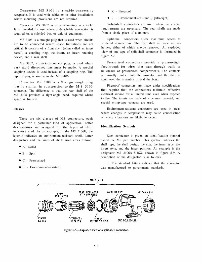
Connec to r MS 3101 i s a c ab l e - connec t i ngreceptacle. It is used with cables or in other installationswhere mounting provisions are not required.
Connector MS 3102 is a box-mounting receptacle.It is intended for use where a detachable connection isrequired on a shielded box or unit of equipment.
MS 3106 is a straight plug that is used when circuitsare to be connected where space limitations are notcritical. It consists of a front shell (often called an insertbarrel), a coupling ring, the insert, an insert retainingdevice, and a rear shell.
MS 3107, a quick-disconnect plug, is used wherevery rapid disconnections must be made. A specialcoupling device is used instead of a coupling ring. Thistype of plug is similar to the MS 3106.
Connector MS 3108 is a 90-degree-angle plugthat is similar in construction to- the M-S 3106connector. The difference is that the rear shell of theMS 3108 provides a right-angle bend, required wherespace is limited.
Classes
There are six classes of MS connectors, eachdesigned for a particular kind of application. Letterdesignations are assigned for the types of shellindicators used. As an example, in the MS 3106E, theletter E indicates an environment-resistant shell. Letterdesignators and the kinds of shells used areas follows:
A- Solid
B - Split
C - Pressurized
E - Environment-resistant
K - Fireproof
R - Environment-resistant (lightweight)
Solid-shell connectors are used where no specialrequirements are necessary. The rear shells are madefrom a single piece of aluminum.
Split-shell connectors allow maximum access tosoldered connections. The rear shell is made in twohalves, either of which maybe removed. An explodedview of one type of split-shell connector is illustrated infigure 5-8.
Pressurized connectors provide a pressuretightfeedthrough for wires that pass through walls orbulkheads of pressurized compartments. The contactsare usually molded into the insulator, and the shell isspun over the assembly to seal the bond.
Fireproof connectors are made under specificationsthat require that the connectors maintain effectiveelectrical service for a limited time even when exposedto fire. The inserts are made of a ceramic material, andspecial crimp-type contacts are used.
Environment-resistant connectors are used in areaswhere changes in temperature may cause condensationor where vibrations are likely to occur.
Identification Symbols
Each connector is given an identification symbolcalled the MS part number. This symbol indicates theshell type, the shell design, the size, the insert type, theinsert style, and the insert position. An example is thedesignator MS 3106A18-4SX, shown in figure 5-9. Adescription of the designator is as follows:
1. The standard letters indicate that the connectorwas manufactured to government standards.
Figure 5-8.—Exploded view of a split-shell connector.
5-9

Figure 5-9.—MS connector marking.
2. The type number indicates the type of shell.
3. The class letter indicates the design of the shell andthe purpose for which the connector is normally used.
4. The size number indicates the shell size. Thissize is either the outside diameter of the mating part ofthe insert or the diameter of the coupling threads (insixteenths of an inch).
5. The insert arrangementarrangement of the contacts innumber of contacts.
number indicates thethe insert but not the
6. The contact style letter indicates that the contactsare of two styles: socket (female), shown by the letterS; or pin (male), shown by the letter P.
7. The insert rotation letter indicates an alternateinsert position. Insert rotation letters W, X, Y, or Zindicate that the insert has been rotated (with respect tothe shell) a specified number of degrees from the normalposition. If the insert is in the normal position, no letteris used.
For more detailed information on types anddesignations of connectors, refer to Handbook o fInstal lat ion Practices for Aircraft Electric andElectronic Wiring, NAVAIR 01-1A-505.
MULTICONDUCTOR CABLES
Engineering electrical and electronic systemsrequire a large variety of electrical cables. Some circuitsrequire only a few conductors having a high currentcapacity. Other circuits require many conductors havinga low current-carrying capacity. A GSE must learn theproper techniques used in cable maintenance.
The engineering control systems on gas turbineships consist primarily of multiconductor cables. Thesecables connect the operating consoles to the respectiveequipment. Figure 5-10 is an example of a multiconductor
cable. Multiconductor cables consist of any number ofindividual conductors. This number ranges from as fewas 2 conductors to as many as 36 conductors.
Splicing Requirements
Some electrical components on gas turbine ships arelocated in areas where they are subjected to salt spray,oil, and water. These conditions can cause connectionsto corrode and conductors to break To connect thesecable faults, the GSE must know how to splicemulticonductor cables properly.
Conductor splices are an essential part of anyelectric or electronic circuit. Any electric or electroniccircuit is only as good as its weakest link. The basicrequirement of any splice is that it be both asmechanically and electrically sound as the conductor ordevice with which it is used. Quality workmanship andproper materials will ensure lasting electrical contactand physical strength.
Joining small, multiconductor cables togetherpresents somewhat of a problem. Each conductor mustbe spliced and taped. If the splices are directly oppositeeach other, the overall size of the joint becomes largeand bulky. You can create a smoother and less bulky jointby staggering the splices.
Figure 5-11 shows how a two-conductor cable isjoined to a similar cable by staggering the splices. In
Figure 5-10.—Multiconductor cable.
Figure 5-11.—Staggering splices.
5-10

performing this procedure, be careful to ensure that ashort wire from one side of the cable being spliced isconnected to a long wire from the other cable. Makecertain the sharp ends are then clamped firmly down onthe conductor. The figure shows a Western Union splicebeing staggered.
Fabrication Procedures
As a GSE, you must learn to fabricate a cable usingconnectors. The type of connector you must use isspecified in the service and overhaul instructions for theparticular equipment.
To fabricate a cable, use the following steps:
1. Disassemble the connector to allow access to thecontacts. Devise a means of holding the connector soyou will have both hands free. (A small bench vise isuseful for this purpose.)
2. Cut the cables to the correct length,
3. Strip the wire ends with a wire stripper or knife.If you use a knife, avoid cutting or nicking the wirestrands.
4. Tin the bare wire ends.
5. Run the wires through the connector assemblyand coupling nuts.
6. See that all surfaces are clean.
7. Flow rosin-core solder into the connectorterminals.
8. Insert each wire into its terminal by holding thetip of the soldering iron against the terminal. As thesolder melts, push the wire into the cavity, and then holdthe wire steady while the solder cools.
CAUTION
Be careful to avoid damaging the connectorinsulation with the soldering iron. When you solder theconnector, the recommended sequence is to start fromthe bottom connection and work from left to right,moving up a row at a time. After soldering theconnections, solder the shields (if used) to a commonterminal on a ferrule. Then lace the cable and reassembleand moistureproof the connector, if necessary.
INSPECTION, MAINTENANCE, ANDREPAIR PROCEDURES
troubleshooting, maintenance, and repair of thesecomponents. In this section, we will briefly describethese areas.
Inspection and Troubleshooting
In the maintenance of cables and connectors, thefirst consideration is a thorough visual inspection. Thischeck should reveal such defects as corrosion, chafing,l oose connec t i ons , b roken w i r e s , ev idence o foverheating, and mismated connectors. You can makeadditional checks to be sure there are no open or shortedconductors in the cable. Usually, you will use anohmmeter to perform these checks.
CAUTION
Many ohmmeters are supplied with test leads thatare slightly larger than the female sockets used inconnectors. Forcibly inserting these probes canirreparably damage the sockets. Exercise care to preventsuch damage.
In reference to the caution, most GSEs make pintesters. Some examples of pin testers are shown in figure5-12. A pin tester is a device constructed of the pins andreceptacles of cannon plugs (view A). The pin tester canalso be a complete replacement cannon plug that has theelectrical cable attached and the ends of the individualwires exposed (views B and C). A pin tester can helpyou prevent short circuits or incorrect readings causedby trying to use ohmmeter or voltmeter test leads to getthe readings from the cannon plugs. The test leads canslip off the pin of the cannon plug and short circuit tothe other pins. This could result in serious damage to thecannon plug or the equipment. Make certain you followall applicable electrical safety precautions when usingfabricated pin testers.
Routine maintenance of electrical connectors andmult iconductor cables involves the inspect ion,
Figure 5-12.—Fabricated pin testers.
5-11

In checking a suspected conductor for either an openor a short, you may have to apply a slight pressure to theconductor or simulate vibration. Shorts are often causedby moisture, foreign particles, or a defective solderconnection at the plug terminals. Therefore, be sure tocheck the connectors carefully before replacing thecable.
Repair and Replacement Procedures
In support equipment, conduit is eliminatedwherever possible . I ts e l iminat ion eases cableinstallation and maintenance. In replacing a cable, takeparticular care to replace it in the exact position in whichit was installed originally. Do not try to reduce the lengthof the cable by taking what might seem to be a logicalshortcut.
When installing or replacing wire or wire bundles,make sure there is no excessive slack along the run.Normally, slack should not exceed a 1/2-inch deflectionwith normal hand pressure. Provide enough slack ateach end to allow for the following:
1. Easy removal and connection of plugs
2. Replacement of terminals two times
3. Prevention of mechanical strain on the wires
4. Free movement of shock and vibration-mountedequipment
5. Shifting of equipment during maintenance
Bends in individual wires should normally belimited to a minimum bend radius of 10 times thediameter of the bundles. However, where the wire issuitably supported at each end of the bend, a radius ofthree times the diameter of the bundles is acceptable.
Wires passing through a bulkhead or structuralmember must be supported at the hole by a cable clamp.If the clearance between the wire and the edge of thehole is less than 1/4 inch, use an approved supportinggrommet in the hole.
Maintain a clearance between wiring and anymovable control. If this cannot be done, install guardsto prevent contact of the wiring with the control. Whenrouting the wiring parallel to plumbing that is carryingflammable fluids, maintain as much separation aspossible. Never support any wire or wire bundle from aplumbing line that is carrying combustible liquids.
Install cable clamps so the mounting screws areabove the wire bundle. (Otherwise the weight of thecable may bend and break the clamp.) If practical, try
to rest the back of the clamp against a structural member.Be careful not to pinch wires in the cable clamp.
LACING AND KNOTTING TECHNIQUESFOR WIRE BUNDLES OR GROUPS.– W i r egroups and bundles should be laced or tied with cord
to provide ease of installation, maintenance, andinspection. This precaution keeps the cables neatlysecured in groups and bundles and helps avoidp o s s i b l e d a m a g e f r o m c h a f i n g o r e q u i p m e n toperation. A wire group is two or more wires tied orlaced together to give identity to an individual system.
A wire bundle is two or more wires or groups tied orlaced together to ease maintenance. A typical example
of wire bundles is shown in figure 5-13.
Materials.— Use cotton, nylon, or fiberglass cord forlacing or tying wire bundles. Make sure the cotton cordis waxed to make it moisture and fungus resistant. Nylonand fiberglass cords are moisture and fungus resistanta n d u s u a l l y w i l l n o t n e e d w a x i n g . U s epressure-sensitive vinyl electrical tape only where theuse of tape is specifically permitted.
The following sections describe some proper lacing
and tying techniques. Refer to figures 5-14 through 5-16as you read these sections.
Precautions.— When lacing or tying wire bundles,observe the following precautions:
1. Lace or tie the bundles tightly enough to preventslipping, but not so tight that the cord cuts into ordeforms the insulation.
2. Do not place ties on that part of a wire group orbundle that is located inside a conduit.
3. Lace wire groups or bundles only insideenclosures, such as junction boxes. Use double cordongroups or bundles larger than 1 inch in diameter. Usesingle or double cord for groups or bundles 1 inch or lessin diameter.
Single Cord Procedure.— To lace a wire group orbundle with a single cord (fig. 5-14), use the followingsteps:
1. Start the lacing at the thick end of the wire groupor bundle with a knot consisting of a clove hitch with anextra loop.
2. At regular intervals along the wire group or
bundle (and at each point where a wire or wire groupbranches off), continue the lacing with half hitches.Space half hitches so the group or bundle is neat andsecurely held.
5 - 1 2

Figure 5-13.—Wire bundles laced and tied in an electrical control panel.
3. End the lacing with a knot consisting of a clove
hitch with an extra loop.
4. Trim the free ends of the lacing cord to a 3/8-inch
minimum.
Figure 5-14.—Single-cord lacing.
5-13
Double Cord Procedure.— To lace a wire group or
bundle with a double cord, use the following steps:
1. Start the lacing at the thick end of the wire group
or bundle with a bowline on a bight.
2. At regular intervals along the wire group or
bundle (and at each point where a wire group branches
off), continue the lacing with half hitches holding both
cords together. Space half hitches so the group or bundle
is neat and securely held.
3. End the lacing with a knot consisting of a half
h i t ch . Use one co rd c lockwi se and t he o the r
counterclockwise. Tie the cord ends with a square knot.
4. Trim the free ends of the lacing cord to a 3/8-inch
minimum.

Branch-off Procedure.— To lace a wire group that
branches off the main wire bundle (fig. 5-15), use thefollowing steps:
1. Start the branch-off lacing with a starting knotlocated on the main bundle just past the branch-off point.When using single-cord lacing, make the starting knotthe same as for regular single-cord lacing. When usingdouble-cord lacing, use the double-cord lacing startingknot.
2. End the lacing with the regular knot used insingle- and double-cord lacing as described earlier.
3. Trim the free ends of the lacing cord to a 3/8-inchminimum.
TYING TECHNIQUES.– You will use specifictying techniques for different conditions. Some of thesetechniques are described in the following sections.
Spacing Ties.— On the all-wire groups or bundleswhere supports are more than 12 inches apart, space ties12 inches or less apart (fig. 5-16).
Figure 5-15.—Lacing a branch-off.
Figure 5-16.—Tying groups of bundles.
Make a tie as follows:
1. Wrap cord around the wire group or bundle.
2. Make a clove hitch, followed by a square knotwith an extra loop.
3. Trim the free ends of cord to a 3/8-inchminimum.
Tying Sleeves.– When tying sleeves to wire groupsor bundles, make the ties the same way as you would forwire groups or bundles.
When it is permitted to use tape, use the followingmethod:
1. Wrap the tape around the wire group or bundlethree times with a two-thirds overlap for each turn.
2. Heat-seal the loose tape end with the side of asoldering iron heating element.
Do not use tape for securing wire groups or bundlesthat may require frequent maintenance.
Using Cable Straps.– Cable straps are adjustable,self-clinching, lightweight, flat, nylon straps withmolded ribs or serrations on the inside surface to gripthe wire. Use cable straps instead of individual cord tiesfor fast securing wire groups or bundles. Cable strapsare available in various sizes and colors to clamp andidentify different sizes of wire groups or bundles.
WIRE WRAPPING
During maintenance and t roubleshooting ofengineering control and surveillance system (ECSS)consoles, take notice of the method used to attach thewires to the backplanes of the consoles. The procedureused is called wire wrapping. In this section, we willdiscuss the principles and techniques involved in thisimportant procedure.
In simple terms, wire wrapping is the process ofusing a series of turns to wrap a single solid wire arounda pin. The equipment on which you would use wirewrapping have long, square pins or posts at the rear ofthe female connectors. The back plane of a console is agood example of this configuration. The pins are longenough to allow one to three wires to be wrapped aroundthem in separate wraps. (A wrap is a single solid wirewrapped around a pin in a series of turns.) The femaleconnectors are then connected from pin to pin by a small,solid-insulated wire, which may or may not be colorcoded.
NOTE: Machine-wrapped assemblies usually donot have color-coded wiring. Hand-wrapped assemblies
5-14.

do have color-coded wiring. The color-coded wire inhand-wrapped assemblies offers an advantage becauseeach wire is distinctive and fewer errors are likely toresult.
PRINCIPLES
The principles behind wire wraps are simple. Forproper conduction to occur between two metals, theoxide coating that has formed on both surfaces must firstbe penetrated. Remember, the pins used in wire wrapsare squared off. They have cornered edges that willpenetrate the oxide coating of the wire when it isproperly wound on the pin. The edges will also lose theiroxide coating when they penetrate the surface of thewire. The junction formed is strong, gastight (tightenough to seal out gases, in addition to liquids), andresistive to corrosion.
MATERIALS
For wire wrapping, a special solid-conductorinsulated wire is required. This type of wire allows thecoil to form tightly about the pin and remain that waywithout noticeable slippage. The wire is a compositionof a silver alloy with a copper coating. Silver offers anadvantage in that its oxide is almost as conductive as themetal itself. The insulation material used on the wire isusually Teflon or Meline. Teflon offers the advantage ofvery high temperature stability and ease of cutting (forstripping by automatic machinery). Teflon, however,also has the undesirable trait of “cold flow.” Cold flowresults when the insulation gradually reduces or wearsaway at a point of pressure. When Teflon-insulated wireis in contact with a pin and cold flow occurs, anintermittent short may occur at that point. Melinewithstands continued exposure to pressure much betterthan Teflon. Although Meline is more resistive to coldflow, it does not have the high-temperature stability ofTeflon. Because of the cold flow problem, however,Meline has become more widely used.
TOOLS
Some ships will have wire-wrap kits for you to use.Other ships may require you to use certain hand toolsauthorized for wire-wrapping procedures. Severaluseful tools, as well as the techniques for using them,have been developed for doing wire wraps. The toolsshown in figures 5-17 through 5-19 provide limitedexamples. For a basic source of wire-wrap tools, referto Gas Turbine Systems Technician (Electrical) 3/GasTurbine Systems Technician (Mechcmical) 3, Volume 1,
NAVEDTRA 10563. For more detailed information onwire-wrap tools and techniques, refer to MILSTD1130B, Notice 2, of 20 July 1983, Connec t i ons ,Electrical, Solderless, Wrapped.
TECHNIQUES
The techniques of wire wrapping are simple. Simplystated, the process involves coi l ing a specialsolid-conductor insulated wire tightly around a pin.Although the process is simple, you must use skill andjudgment to perform the steps correctly. Refer to figure5-17 as you read the following paragraphs.
Using Correct Procedures
Your first step in wire wrapping is to determine thecorrect gauge of wire you need to perform the job. Strip
Figure 5-17.—Basic wire-wrap procedure.
5-15

off enough insulation to allow the correct number ofturns to be wound around the pin. Then, either place theend of the wire in a long shallow groove along the barrelof the wire-wrap tool or insert it into the smaller hole atthe end of the barrel, as shown in view A of figure 5-17.The groove (or hole) for the wire is carefully sized toprovide the exact amount of tension you will need toform a secure wrap. Make certain the insulation bottomsinto the wire funnel, as shown in view B. This will allowyou to wrap the correct amount (one to one and a halfturns) of insulated wire around the wrap pin. Anchor thewire by bending it into the notch in the sleeve, as shownin view C. Next, slip the center hole at the end of thebarrel down over the pin, as shown in view D. Thenrotate the barrel around the pin. (Depending on thedesign of the wire-wrap tool, the barrel will rotate as aresult of finger, hand, or motor action.) The wire shouldtwist around the pin, as shown in view E. As the wiretwists around the pin, the stripped portion of the wirethat is being held in the groove (or in the other base hole)will be drawn down to twist and coil around the pin. Thecoiling action of the wire on the pin lifts the tool enoughfor you to continue the wire coil up the pin, as shown inviews F and G. Your skill is especially important at thispoint because too much pressure on the tool will causethe coils to bunch or overlap. If you are replacing a wire,carefully run the wire to the next connection andperform the same procedure on the opposite end. Be sureyou allow enough spare wire for the required number ofwraps on the pin.
Before actually doing a wire wrap on the item youare repairing, take time to practice this procedure. Finda spare connector or spare pin similar to those you willrepair. Using the same materials required for the actualjob, practice a few times. Figure 5-18, view A, shows agood wire wrap. It has five to seven and a half snug turnsof wire. Place the insulation about the bottom one or twoturns with no spacing between adjacent turns, nobunching as one turn tries to cover another, and noobservable nicks in the wire. The number of turns youwill use is based on the wire gauge. Wires and pins withlarger diameters require fewer turns; those with smallerdiameters require more turns.
Avoiding Errors
The fo l l owing l i s t de sc r ibe s a va r i e ty o fINCORRECT wire-wrapping techniques. Some ofthese faults are evident in the numbered sections in viewB of figure 5-18.
1. Not enough tension on the wire, resulting in aloose connection. You can detect this fault by the open
Figure 5-18.—Correct and incorrect wire wraps.
spaces between adjacent turns. (See fig. 5-18, view B,
sec. 1.)
2. Overtension on the wire, resulting in a loose
connection. You can detect this fault by the turn overlaps
and the fact there is not enough surface contact with the
pin. (See sec. 3.)
3. Insufficient number of turns (fewer than five),
resulting in poor contact. (Not enough wire was stripped
first.) (See sec. 4.)
4. Insulation does not extend to the pin, resulting
in increased chances of shorts or wire breaks. (Too much
wire was stripped.) (See sec. 7.)
5. Reuse of uncoiled wrap. (Each reuse increases
the likelihood of wire breaks.)
6. Attempts to wrap by hand, resul t ing in
insufficient and uneven tension and poor contact.
5-16

Removing a Wire Wrap
Normally, you should use a wire-wrap removal tool,as shown in view A of figure 5-19, to remove a wirewrap. This precaution will prevent stress and possibledamage to the wire-wrap pin. If you must remove thewire by hand, however, unwrap the wire without
applying stress to the pin. You can accomplish this bygently uncoiling the wire with a slight rotatingmovement over the point of the pin. Make sure that themanner in which you remove the wire does not causemovement of the pin itself, as shown in view B. If a pinis bent, it will probably break when an effort is made to
straighten it. If a pin breaks, first ensure that the brokenlength is not left in the wiring to cause possible shorts.
Then take the necessary steps to install a new pin.
Figure 5-19.—Wire-wrap removal procedures.
Normally, inner wire wraps are placed near the bottomof the pin to assure that additional wraps can be addedeasily. If you have to remove a lower wire wrap, firstremove each wrap above it. Do not remove a wire wrapby trying to pull it along its axis, as shown in view B.Remember, each wrap is easily identified because it isformed from the multiple turns of a single solid wire.
When removing a wire wrap from a pin, you mustbe careful not to disturb other wraps on the same oradjacent pins or to dislodge the pin. This would causepoor continuity or an open circuit.
ADVANTAGES AND DISADVANTAGES
As with any process, certain advantages anddisadvantages are associated with wire wrapping. Agood technician can recognize the pros and cons and canu s e t h i s k n o w l e d g e f o r m a i n t e n a n c e a n dtroubleshooting purposes. A few of the advantages anddisadvantages are discussed in the following sections.
Pros
Some of the advantages associated with wirewrapping are described in the following list:
1. It is a simplified technique for repairs. (YOU canjust uncoil the wires to remove them and use the propersimple tool to replace them.)
2. There is no possibility for solder spills. (Thismeans you can make repairs without removingcomponents.)
3 . There is no danger of the componentsoverheating. (This is not the case in solderingprocesses.)
4. You can perform more in-equipment repairs, andrepair times are faster.
5. There is no danger of burns to ship’s personnel.(This is not the case when hot soldering irons are used.)
6. It provides for durable electrical contact. (Theresults are just as good as those achieved with goodsoldering techniques, and better than those resultingfrom bad soldering.)
Cons
Recognizing the cons of wire wrapping will helpyou in some of your troubleshooting efforts. Thefollowing list describes some of the cons:
5-17

1. Sol id wire must be used; therefore, thelikelihood of wire breakage is increased.
2. Problems, such as cold flow, can occur with theinsulation.
3. Wire wrapping is not suitable for subminiatureassemblies.
4. There is no wire color coding in machine-wrappedassemblies.
5. The process requires clipping off the wrappedportion of the wire and stripping back the insulation toexpose the new wire before you make the next wrap. Ifthe wire is too short, you must replace it. You cannotreuse the same portion of wire in a new wrap becausethis area will have been structurally weakened by nicksfrom the previous use, and you will weaken it evenfurther if you reuse it.
SAFETY PRECAUTIONS
Use caut ion when working with wire-wrapassemblies. Wire-wrap assemblies resemble a bed ofnails, and several people have become injured bydisregarding the proper safety precautions. Severalfacial injuries have occurred when technicians havetried to get a good look at these assemblies from the side.You should remember that this position can expose youreyes to a needless hazard. If you must use this positionto get a firsthand view, use sufficient lighting to makeout the details, use small mirrors whenever you can, andwear safety goggles. When inspecting or repairing theback planes or other areas of possible damage,remember that ac or dc voltages may still be present.Always make certain you are using the proper safetyprecautions for working with energized equipment.
ELECTROMECHANICAL CONTROLSYSTEMS MAINTENANCE
Gas turbine-powered ships are becoming moreautomated and complex with each class of shipdelivered to the Navy. This complexity is visible inmostof the equipment the GSEs maintain. Electromechanicaldevices have also become more complex. The GSEr a t i n g i s r e s p o n s i b l e f o r m a i n t a i n i n g t h e s eelectromechanical devices in peak operating condition.
There are several devices on gas turbine ships thatare classified as electromechanical devices. Thesedevices include the following components:
Motor-operated valves
Solenoid-operated valves
Remote-indicating valves
Electrical controllers
Bus transfer switches
The GSE’s counterpar t , the GSM, performsmaintenance on the mechanical parts of the valves. TheGSE performs maintenance on all electrical parts of thevalves. These two ratings must work closely with eacho t h e r w h e n p e r f o r m i n g m a i n t e n a n c e o n t h e s eelectromechanical devices.
MOTOR-OPERATED VALVES
Motor-operated valves provide a means for aconsole operator to operate essential valves remotely.Motor-operated valves are found on fuel oil servicetanks, fuel oil storage tanks, and the main seawatercooling system of some gas turbine-powered ships.
A motor-operated valve is nothing more than avalve, a motor, and a reversing controller. Mostmotor-operated valves also contain microswitches toshow the valve’s position. The console operator pusheseither an open or a close push button. The resultingsignal is sent to the reversing controller of the valve,thereby opening or closing the valve. An actuating rodin the valve rotates or slides, depressing either the openor close microswitch. The signal from the microswitchis then sent backup to the console, indicating the valve’sposition.
The maintenance on motor-operated valvesi n c l u d e s i n s p e c t i n g , c l e a n i n g , t e s t i n g , a n dtroubleshooting the motor and controller. Thesemaintenance procedures are the same procedures youwould use to maintain basic motors and controllers.These maintenance procedures will be described later inthis chapter.
SOLENOID-OPERATED VALVES
Solenoid-operated valves are used extensively ongas turbine-powered ships. These valves are located inthe bleed air system, the start air system, and the prairieand masker air system. Solenoid-operated valves arealso found on the gas turbine generator and the mainpropulsion turbine systems.
Construction and Operation
A solenoid-operated valve consists of a valve(needle, poppet, or spool) and a solenoid. Most
5-18

solenoid-operated valves also contain microswitches toshow the valve’s position. The console operatordepresses a pushbutton to cycle the valve to a newposition. This signal is sent to the solenoid of the valve.Depending on the signal received, the solenoid cyclesthe valve to the requested position. An actuating rod inthe valve rotates or slides, depressing a microswitch.The signal from the microswitch is sent backup to theconsole, indicating the valve’s position.
The maintenance on solenoid-operated valvesi n c l u d e s i n s p e c t i n g , c l e a n i n g , t e s t i n g , a n dtroubleshooting the solenoid and the microswitches.The procedures used to maintain and troubleshootmicroswitches were discussed earlier in this chapter. Wewill now briefly describe the maintenance proceduresassociated with solenoids.
To properly troubleshoot a solenoid, you must firstknow how it is constructed and how it works. Figure5-20 is a cutaway view of a solenoid showing thesolenoid action. A solenoid is an electromagnet formedby a conductor wound in a series of loops in the shapeof a spiral. Inserted within this coil is a soft-iron coreand a movable plunger. The soft-iron core is pinned orheld in an immovable position. The movable plunger(also soft iron) is held away from the core by a springwhen the solenoid is de-energized. Notice the position
Figure 5-20.—Solenoid action.
of the plunger in view A when the coil is de-energized.Compare view A with view B, which shows the plungerposition when the coil is energized. When current flowsthrough the conductor, it produces a magnetic field. Themagnetic f lux produced by the coi l resul ts inestablishing north and south poles in both the core andthe plunger. (See view B.) The plunger is attracted alongthe lines of force to a position at the center of the coil.As shown in view A of figure 5-20, the de-energizedposition of the plunger is partially out of the coil due tothe action of the spring. When voltage is applied, thecurrent through the coil draws the plunger within thecoil, resulting in mechanical motion. When the coil isde-energized, the plunger returns to its normal positionbecause of spring action. The effective strength of themagnetic field on the plunger varies according to thedistance between the plunger and the core.
Maintenance of Solenoids
If you suspect that a solenoid is not workingproperly, your first step in troubleshooting is a goodvisual inspection. Check the connections for poorsoldering, loose connections, or broken wires. Check theplunger for cleanliness, binding, mechanical failure, andimproper alignment. Check the mechanism to which thesolenoid is connected (actuates) for proper operation.
Your second step is to check the energizing voltagewith a voltmeter. If the voltage is too low, the result isless current flowing through the coil and a weakmagnetic field. A weak magnetic field can result in slowor poor operation. Low voltage could also result inchatter or no operation at all. If the energizing voltageis too high, it could damage the solenoid by causingoverheating or arcing. In either case, you should resetthe voltage to the proper value so that further damage orfailure of the solenoid will not result.
Next, check the solenoid coil with an ohmmeter foropens or shorts, and the proper resistance. If the solenoidcoil is open, current cannot flow through it and themagnetic field is lost. A short results in fewer turns andhigher current in the coil. The net result of a short is aweak magnetic field. A high-resistance coil will reducecoil current and also result in a weak magnetic field. Aweak magnetic field will cause less attraction betweenthe plunger and the core of the coil. This will result inimproper operation similar to that caused by lowvoltage. If the coil is open, shorted, or has changed inresistance, the solenoid should be replaced.
Finally, you should check the solenoid to determineif the coil is shorted to ground. If you find a short to
5-19

ground, remove the short to restore the solenoid toproper operation.
REMOTE-INDICATING VALVES
A remote-indicating valve is a manually-operatedvalve that gives a remote indication of the valve’s status.One example of this type of valve is the primary manualvalves used in the fuel oil transfer and recirculatingsystem on DD-, DDG-, and CG-class ships. Thesevalves are equipped with open and close limit switches.These switches provide open and close signals to thefuel system control console (FSCC) and the associatedfuel oil local control panel indicator lights.
A remote-indicating valve is a manual valve withtwo microswitches (limit switches). The valve ismanually opened or closed. When the valve reaches itsdesired position, a tang or lobe attached to the valve stemactuates the appropriate limit switch. The switch sendsthe signal to the console to illuminate the associatedindicator light.
The maintenance of remote-indicating valvesi n c l u d e s i n s p e c t i n g , c l e a n i n g , t e s t i n g , a n dtroubleshooting the limit switches. The procedures usedto maintain and troubleshoot microswitches (limitswitches) were discussed earlier in this chapter.
ELECTRICAL CONTROLLERS
The most common electromechanical device usedin the Navy is the electrical controller (motor controller).A motor controller functions to protect a motor fromdamage, to start or stop it, to increase or decrease itsspeed, or to reverse its direction of rotation. The GSErating is responsible for the maintenance of severaldifferent types of electr ical control lers in theengineering department.
Electrical controllers can be found throughout theengine rooms of gas turbine-powered ships. They areused on space ventilation fans, motor-operated valves,turbine enclosure cooling fans, and various pumps andmotors. The maintenance of these components andsystems is the responsibility of the GSEs. As a GSE, youmust be able to recognize proper operation of acontroller and to take actions to correct any problem thatarises.
Controller Maintenance
Proper preventive maintenance lessens the chancesof failure of electrical controllers. Since electricalcontrollers are electromechanical devices, they often
tells you that you have voltage to the source side of theline fuses. You can also check between the other lines.To check the fuse in line 1 (L1), place the voltmeteracross the line fuse, as shown at position B betweenL1-L2. A voltage reading shows a good fuse in L1.Likewise, check the other two fuses between L1-L3 andL2-L3. A no-voltage reading would show a faulty fuse.
If the line fuses check good and the main contactsare closed, then check the voltage between terminals
5-20
give into mechanical failure. Center your attention inthese areas. Electrical controllers do have electricalproblems, but most of the problems stem from themechanical interface within the controllers. In general,when a controller fails to operate or signs of trouble(heat, smoke, unusual noise, or smell of burning) occur,you can find the cause of the trouble by a simpleexamination. This consists of using your sense of feel,sight, sound, or smell. At other times, however, findingthe trouble will involve a more detailed process. See theappropriate manufacturer’s technical manual for a listof common troubles, their causes, and the correctiveactions.
Imagine you are a GSE on a gas turbine-poweredship. You are sent to investigate an apparent electricalcontroller system failure. You first press the STARTbutton (or, in the case of motor-operated valves, theOPEN or CLOSE button). When this does not start thesystem, you press the RESET push but tons ( i fapplicable). Now you try to start the motor. If the motoroperation is restored, you will not need to performfurther checks. If the motor still fails to start, however,you must check the motor circuit for continuity. If themain contacts fail to close, you must check the controlcircuit for continuity.
In the following paragraphs, we will guide yout h r o u g h a p r o c e d u r e f o r t r o u b l e s h o o t i n g amotor-controller electrical system. We will describe thesequence of steps you should follow in locating a fault.Refer to figure 5-21 as we take you through this process.First, let’s analyze the power circuit, and then the controlcircuit.
Power Circuit Analysis
When no visual signs of circuit failure are clear andan electrical failure is indicated in the power circuit, firstcheck the line voltage and fuses (or circuit breaker), asshown in figure 5-21. Place the voltmeter probes on theline side of the fuses, as shown at position A. (Thesymbol VM refers to your voltmeter.) A line voltagereading tells you that your voltmeter is operational. It

Figure 5-21.—Troubleshooting a 3-phase magnetic controller.
T1-T2, T2-T3, and T1-T3. The controller is faulty ifthere are no voltmeter readings on all three of theterminal pairs. You should then proceed to check themain contacts, overloads, and lead connections withinthe controller. However, if there is voltage at all threeterminals, the trouble is either in the motor or the wiresleading to the motor.
Control Circuit Analysis
Suppose the overload reset buttons have been resetand the START button is closed. If the main contacts donot close, check the control circuit. Your testingprocedure should include the following steps:
1.
2.
3.
Check for voltage in the controller at L1, L2, andL3.
Place the voltmeter probes at points C and D (fig.5-21). You should have a voltage reading whenthe STOP button is closed. You should have ano-voltage reading when the STOP button isopen. These conditions would indicate a goodSTOP button and control circuit fuse.
Next, check the voltage between points C and E.The START button is good if you get ano-voltage reading when the START button isopen. The START button is also good if you get
4.
5.
a voltage reading when the START button isclosed.
Place the voltmeter probes at points C and F. Avoltage reading with the START button closedwould indicate a good OL1. It also wouldindicate one of the following components isopen: OL3, the main coil, the control fuse, or
the connection to L3.
Place the voltmeter probes at points C and G.
Close the START button. A no-voltage readingwould indicate that the trouble is located in thecontrol circuit to OL3.
The following conditions would indicate a faulty
auxiliary contact: (1) The system operates only as long
as the START button is depressed; and (2) when thebutton is released, the system shuts down.
When starting a 3-phase motor, if the motor fails tostart and gives a loud hum, you should stop the motorby pushing the STOP button. These symptoms usuallymean one of the phases to the motor is not energized.You can assume the control circuit is good. This isbecause the main coil has operated and the auxiliary
contacts are holding the main contactor closed. Look fortrouble in the power circuit (the main contacts, overloadrelays, cable, and motor).
In the GSE rating you will come across various
types of control circuits. Some control circuits are morecomplex than the one shown in figure 5-21, while othersare simpler. The troubleshooting principles we have justdescribed will work on any type of control circuit. You,however, as the technician, must make certain you havethe correct schematics when you are troubleshootingany type of electrical controller.
BUS TRANSFER EQUIPMENT
Bus transfer equipment is installed at load centers,
distribution panels, or loads that are fed by both normaland alternate, or emergency feeders. Bus transfer
equipment allows you to select either the normal oralternate source of ship’s service power. If an emergencyfeeder is provided, the bus transfer unit will also allow
you to get power from the emergency distributionsystem.
Automatic bus transfer (ABT) equipment allows
you to select between two power supplies to obtainpower for the following systems:
1. Emergency lighting
5-21

2.
3.
4.
Interior communication switchboards andpanels
ECSS consoles
Steering power panels
Manual bus transfer (MBT) units are used for allloads having low voltage protection (LVP) controlfeatures, except in the case of pumps associated with themain and auxiliary machinery plant which have theirown low voltage release (LVR) control features. MBTunits are also used for loads having manual restart aftera voltage failure and for electronics power distributionpanels. Loads that have LVR or LVP control features andrequire two sources of supply are sometimes combinedand supplied from an ABT unit. MBT units are locatedas close as possible to the panel or equipment being fedfrom the bus transfer unit.
On power systems, there is a short time delay afterthe normal feeder is de-energized and before the ABTswitch takes over. During this shift, the load is withoutpower. Remember, however, that ABT switches onlighting systems have no time delay and transfer powerinstantaneously.
Testing
Bus transfer equipment should be tested accordingto your ship’s preventive maintenance system (PMS)schedule. For MBT equipment, manually transfer a loadfrom one power source to another . Check themechanical operation and mechanical interlocks of theMBT. For ABT equipment, check the operation by usingthe test switches. Your test should include a check to seeif operation starts after you cut off power (by openingthe feeder circuit breaker). This check will confirm thatthe automatic transfer unit is working.
CAUTION
When you are testing the ABT units, be careful theydo not supply vital and sensitive electronic circuitry.Some sensitive electronic circuits are adversely affectedby a loss and almost instant return of power. Beforeconducting the test, make certain all personnelconcerned are informed of the power interruptions.
Be careful when testing an MBT unit. Make certainyou follow the correct procedure when shifting an MBTfrom normal to alternate power. You should getpermission from the EOOW before starting the test ofan MBT. Failure to do so could cause loss of vitalequipment that is on line.
Maintenance
If any problems are discovered during the testing ofbus transfer equipment, you, as the GSE, must correct
them immediately. Remember to follow all standarde l e c t r i c a l s a f e t y p r e c a u t i o n s w h e n y o u a r etroubleshooting and repairing bus transfer equipment.
Your first step in the maintenance of bus transferequipment is to perform a functional check of the ABT
or MBT. You will normally follow the applicable PMScard to perform this check. Your check should includecycling or shifting the bus transfer equipment from thenormal to the alternate power source and vice versa.
Observe the operation and note any problems that occur.
Use the correct procedures for performing afunctional check of an MBT by taking the followingsteps:
1. Make certain the alternate power indicator lampis on, showing that alternate power is available.
2. Open the normal power circuit breaker (CB).
3. Shift the interlock to prevent closure of thenormal power CB, and enable the closure of the alternate
power CB.
4. Close the alternate power CB.
Using these steps, you will shift the MBT back to
the normal power source. The MBT shifting process is
purely a mechanical one. If power is not transferredduring the functional check, look for a faulty CB in theMBT unit.
You can perform the functional check of an ABT in
two ways. First, manually test the ABT by placing thecontrol disconnect switch in the MANUAL position andshifting the manual switch to the opposite position. (See
fig. 5-22.) Second, automatically test the ABT byplacing the control disconnect switch in the AUTO
position and turning the spring-loaded test switch to theTEST position. The ABT should shift to the alternate
power source. Releasing the spring-loaded test switchallows the ABT to shift back to the normal source ofpower. If the ABT fails to perform in this reamer, youmust begin troubleshooting.
Various types of ABTs are used throughout theNavy. You must make certain you get the correctmanufacturer’s technical manual before you begin to
troubleshoot and repair the ABT. Once again, follow all
standard electrical safety precautions when working onthis equipment.
5-22

Figure 5-22.—Pictorial view of an ABT.
As a good maintenance technician, you should tryto local ize the problem by fol lowing the basictroubleshooting steps. In troubleshooting the ABT, youshould first make certain that both power sources areavailable to the ABT. If both sources are available, youwill then have to de-energize both sources of power andtag the ABT out of service. First check the mechanicaloperat ion of the ABT, then make an electr icalexamination. After you locate the faulty part, remove itand replace it. Your final step in troubleshooting theABT is testing the effectiveness of your repair.
These troubleshooting steps are general in nature.Always use the manufacturer’s technical manual and theappropriate troubleshooting charts whenever you arerepairing or replacing components of MBTs and ABTs.
ELECTROHYDRAULIC CONTROLSYSTEMS MAINTENANCE
An electrohydraulic control system is one that useselectrical or electronic signals and components tocontrol the flow of oil or hydraulic fluids. On gast u r b i n e - p o w e r e d s h i p s , t h e m o s t i m p o r t a n telectrohydraulic control system is the controllablereversible pitch (CRP) propeller or controllable pitchpropeller (CPP) system. This system is called thepropeller pitch control system on the landing craft, air
cushion (LCAC) vessels. The purpose of CRP/CPPsystem is to provide the ahead and astern propulsionthrust for a ship by changing the pitch of the propellerblades.
The operation, maintenance, and repair of the CRP,CPP, and propeller pitch systems are within thecapabilities of ship’s personnel. Since these systemsinterface electronics with mechanical operations, theGSEs must work closely with the GSMs whentroubleshooting and repairing these systems.
DD-963/DDG-993 CLASS SYSTEM
The pitch of the CRP propellers is establishedelectrically through two identical electrohydraulic pitch
control systems. One is located in each main engineroom. Each system has two basic parts or groups of
components. These are the CRP electronics enclosureand the oil distribution (OD) box-mounted components.The OD box-mounted components consist of theelectrohydraulic servo control valve and two slide-typepotentiometers. Figure 5-23 shows the relationshipbetween the two basic parts of the system. Refer tofigure 5-23 as you read the following paragraphs.
The procedures you will use to troubleshoot theelectrohydraulic servo control valve are the same asthose we discussed for troubleshooting solenoids. Theservo valve consists of a two-coil solenoid. Each coilhas a dc resistance of about 1000 ohms. Check this with
an ohmmeter. The total resistance of the solenoid shouldread 500 ohms when you measure it from the twoconductors that run between the electronic enclosureand the terminal box.
The linear feedback and shaped potentiometers(LINEAR POT and SHAPED POT in fig. 5-23) aremounted side by side on the top of the OD box. Each
potentiometer is housed in a rectangular box about 18inches long, 1 1/2 inches wide, and 1 1/2 inches tall. A
shaft that moves the sliding contact extends out of theforward end of each potentiometer box. A Y-shaped
yoke connects the ends of the potentiometer that extendout the forward end of the OD box. The follow-up rodprovides a mechanical positioning of the potentiometershafts that corresponds to actual propeller pitchpositions. The follow-up rod also positions a mechanicalpointer along a calibrated scale mounted between thepotentiometers. Slots in the potentiometer mounting feetprovide for longitudinal position adjustments when you
are calibrating the zero pitch feedback and readoutsignals.
5-23

Linear Potentiometer
Figure 5-23.—E1ectrohydraulic signal flow between CRP components.
The l inear potentiometer provides the pi tchfeedback signal to the servo valve controller card in theCRP electronics enclosure. The resistance element isabout 10 kilohms from end to end. The term linearmeans that the resistance is evenly distributed along thepotentiometer body. The voltage picked up by thesliding contact is proportional to its position along thepotentiometer body.
Shaped Potentiometer
The shaped potentiometer generates the pitchreadout signal that is used to display pitch on the digitaldemand display at the ECSS operating stations. Theresistance across the shaped potentiometer from end toend is about 15 kilohms. The term shaped is used todescribe this potentiometer because the resistance is notevenly distributed along the potentiometer body. Thereis slightly more resistance at the ends than in the middle.This non-linear resistance distribution is necessary tocounteract the increased sensitivity of the propeller pitchwhen the valve rod is at the extreme ahead or astern pitchsettings.
CRP Electronics Enclosure
The CRP electronics enclosure is a rectangular casethat contains six circuit cards. These cards are pluggedinto receptacles for easy removal and replacement fromthe front. The CRP electronics enclosure front panel isshown in figure 5-24. A printed circuit board, containinga diode rectifier bridge, is bolted to the top of theenclosure. Study figure 5-24 as you read the descriptions
5-24
of the enclosure power supply and module circuit cardsin the following paragraphs.
±28V DC POWER SUPPLY.— The power supplyreceives 115 volts ac, single phase power from the
propulsion local operating equipment (PLOE) consolethrough two 3-amp fuses. The incoming 115 volts ac isreduced to 45 volts ac by a step-down transformer. This
voltage is then rectified by the rectifier circuit board toprovide a +25 and a -25 volt dc source. Three +25 volt
dc bus lines and three -25 volt dc bus lines carry powerthroughout the enclosure.
± 15V DC VOLTAGE REGULATOR.— Two ±15volt dc voltage regulator circuit cards supply regulated
power (±.015 volt dc variance for either +15 volts dc or-15 volts dc) to other circuit card modules. Several test
point jacks and a failure alarm light are mounted on theregulator card front panels. There are two output voltage
trimmer potentiometers mounted on the front panels ofthe regulator card.
SERVO VALVE CONTROLLER CARD.— This
c a r d p r o v i d e s t h e s i g n a l t h a t o p e r a t e s t h e
electrohydraulic servo control valve on the OD box. The
pitch command signal from the ECSS comes into thiscard and is summed with the feedback voltage from thelinear potentiometer. These two signals are compared
and a correcting signal is sent to the servo valve ifnecessary. The front panel of the servo valve controller
card has three recessed potentiometers. Two of thepotentiometers provide separate gain adjustments forahead and astern pitch command signals. The third
potentiometer feeds a small voltage to the commandinput and feedback summing junction to compensate formisalignment of the linear potentiometer. The servo

Figure 5-24.—DD-963 CRP eletronics enclosure front panel.
valve control ler card also supplies the l inearpotentiometer with +15 volts dc and -15 volts dc.
FIVE-POINT LEVEL DETECTOR CIRCUITCARD.– The five-point level detector causes thefive-point indicator light assembly on the PLOE todisplay the actual propeller pitch. This is accomplishedby using the signal from the shaped potentiometer. Thelabels on the five indicator lights identify the conditionsFULL AHEAD PITCH, AHEAD PITCH, ZEROPITCH, BACK PITCH, or FULL BACK PITCH. Thisdisplay of five indicator lights is also provided on thefront panel of the built-in test equipment (BITE) circuitcard for ease of testing and calibration. The five-pointl eve l de t ec to r ca rd a l so supp l i e s t he shapedpotentiometer with +10 volts dc on one end and zerovolts on the other end.
ANALOG TO DIGITAL (A/D) CONVERTERCIRCUIT CARD.– The A/D converter output providesthe digital signals to ECSS for display of the actualpropeller pitch. Actual propeller pitch is displayed onthe digital demand readouts in the engine rooms and inthe central control station (CCS). The A/D converterreceives the shaped potentiometer signal from thefive-point level detector card. This signal is within therange of 0 to + 10 volts dc The signal is changed by theA/D converter circuitry to a nine-bit binary signal. Thisbinarn, signal is sent to the ECSS signal conditioningenclosure (S/CE).
BUILT-IN TEST EQUIPMENT CIRCUITCARD.– The BITE card contains the local indicating
lights that constantly check the five-point level detectorand A/D converter outputs. The indicating lights are redlight emitting diodes (LEDs) mounted in the circuit cardfront panel. These lights provide maintenance personnelwith a local indication of the five-point level detectoroutput being sent to the PLOE. There are nine A/D bitlights that check the output of the A/D converter. Theyare located on the upper half of the BITE card frontpanel. Each light monitors one of the nine digital outputlines. An illuminated light indicates a digital logic “one,”which is about 5 volts dc. A darkened light indicates adigital logic “zero,” which is about 0 volt dc These lightsare designed primarily to aid in calibration and testingof the A/D converter.
CG-47 CLASS SYSTEM
The CRP propeller system on the CG-47 class shipsis almost identical to the DD-963 system just discussed.The primary difference is the potentiometer setup on theOD box and one card in the CRP electronic enclosure.The OD box has only one potentiometer that sendssignals for both indication and control.
Figure 5-25 shows the CRP electronics enclosurefront panel found on CG-47 class ships. Notice that theA/D converter circuit card in the electronics enclosurehas been replaced with a slew rate controller circuit card.The purpose of the slew rate controller card is threefold.First, it provides an integrated “burst” signal to the servovalve. This signal is of correct polarity to preventsticking of the valve and possibly overdriving the actual
5-25
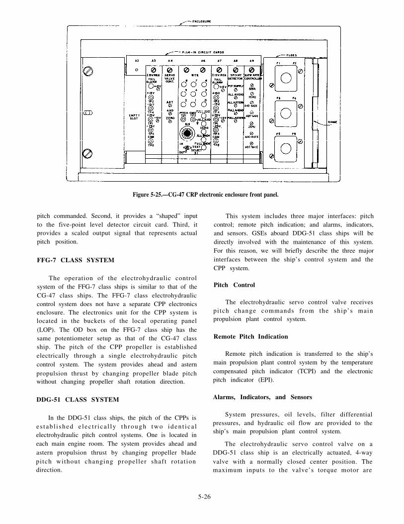
Figure 5-25.—CG-47 CRP electronic enclosure front panel.
pitch commanded. Second, it provides a “shaped” input This system includes three major interfaces: pitchto the five-point level detector circuit card. Third, itprovides a scaled output signal that represents actualpitch position.
FFG-7 CLASS SYSTEM
The operation of the electrohydraulic controlsystem of the FFG-7 class ships is similar to that of theCG-47 class ships. The FFG-7 class electrohydrauliccontrol system does not have a separate CPP electronicsenclosure. The electronics unit for the CPP system islocated in the buckets of the local operating panel(LOP). The OD box on the FFG-7 class ship has thesame potentiometer setup as that of the CG-47 classship. The pitch of the CPP propeller is establishedelectrically through a single electrohydraulic pitchcontrol system. The system provides ahead and asternpropulsion thrust by changing propeller blade pitchwithout changing propeller shaft rotation direction.
DDG-51 CLASS SYSTEM
In the DDG-51 class ships, the pitch of the CPPs ise s t ab l i shed e l ec t r i ca l l y t h rough two iden t i ca lelectrohydraulic pitch control systems. One is located ineach main engine room. The system provides ahead andastern propulsion thrust by changing propeller bladepitch without changing propel ler shaft rotat iondirection.
control; remote pitch indication; and alarms, indicators,and sensors. GSEs aboard DDG-51 class ships will bedirectly involved with the maintenance of this system.For this reason, we will briefly describe the three majorinterfaces between the ship’s control system and theCPP system.
Pitch Control
The electrohydraulic servo control valve receivespi tch change commands from the ship’s mainpropulsion plant control system.
Remote Pitch Indication
Remote pitch indication is transferred to the ship’smain propulsion plant control system by the temperaturecompensated pitch indicator (TCPI) and the electronicpitch indicator (EPI).
Alarms, Indicators, and Sensors
System pressures, oil levels, filter differentialpressures, and hydraulic oil flow are provided to theship’s main propulsion plant control system.
The electrohydraulic servo control valve on aDDG-51 class ship is an electrically actuated, 4-wayvalve with a normally closed center position. Themaximum inputs to the valve’s torque motor are
5-26

±10 volts dc. The polarity of the ±10-volt dc process back, an indication signal representing actual
signal determines the direction of pitch change. The size position back to the remote control stations.valve rod
of the signal determines the rate of pitch change.LCAC SYSTEM
The ahead or astern pitch signal from remote
operating stations is fed directly to the electrohydraulic In an LCAC, the purpose of the propeller pitchservo control valve. The pitch signal routed to the control system is to allow the operator to control the
electrohydraulic servo control valve is direct ly speed and direction of the craft by changing the
proportionate to the amount of pitch desired. A linear propeller pitch. The propeller is capable of forward or
potentiometer is mounted on the pitch scale of the TCPIreverse pitch. The greater the angle of pitch, the fasterthe craft will move. The propellers are controlled by two
assembly. The mechanical arm indicator is also attached control levers located on the left-hand console of theto an actuating rod of a linear potentiometer. The operator control station and yoke in and out movement.function of the linear potentiometer is to transfer, or feed (See fig. 5-26.)
Figure 5-26.—LCAC steering control station.
5-27

The propeller pitch control system is composed ofthe yoke assembly, propeller pitch indicator, a controlunit, pitch levers, potentiometers, and amplifiers.Pushing the yoke in or pulling it out will cause electricalsignals to be sent to the electrohydraulic servo valve andactuator, which permits the operator to control the pitchof the propellers. (Refer to fig. 5-27). An indicator at theoperator station provides an indication of propellerpitch.
Electrical control signals for the propeller pitchcontrol are generated by the propeller pitch levers andby moving the yoke in and out. The propeller pitchlevers set the center point for the plus and minus, in andout, movement of the yoke. Inward movement causes apitch increase; outward movement causes a pitchdecrease. Placing the propeller V PITCH switch in theOFF position takes the yoke out of the propeller pitchcontrol system. Propeller pitch is then controlled by thepropeller pitch levers. The propeller pitch signals aresent through the control systems electronic package(CSEP) to the propeller. If a CSEP malfunction occurs,
a secondary CSEP channel maybe selected by using thecommand and control keyboard. The control voltagesupplied to the propeller pitch control has a positive tonegative voltage range.
TROUBLESHOOTING CRP/CPP SYSTEMS
For a GSE, familiarity with normal gauge readingsand maneuvering times under varying conditions isessential to troubleshooting electrohydraulic controlsystems. Normal operating pressures will vary alongwith the following conditions:
Changes in shaft speed
At every posi t ion change throughout thepitch-changing stroke
Between shaft sets because of manufacturingtolerances
As an operator or maintenance technician, youshould avoid making any variations from these norms.
Figure 5-27.—LCAC propeller pitch control system.
5-28
When trouble occurs, examine the system, determinethe cause, and record your findings.
Whenever you are troubleshooting pitch controlsystems, using the appropriate manufacturer’stroubleshooting guide is essential. This guide isprovided as an aid to troubleshooting and correctingfaults that may occur in the propeller pitch system.The troubleshooting guide contains a description ofsymptoms noticeable to the operator along with a listof possible causes. Using this guide allows you todirect your attention to a specific component. Beingable to identify both the type of malfunction and thefaulty component will allow you to make a logicaldecision to repair, replace, or investigate further.Remember, a complete loss of control is most oftencaused by two malfunctioning components actingtogether. Either component alone might not cause anynoticeable impairment of operation. Repairing onecomponent may restore operation, however, it mayalso set the stage for a recurrence should a secondmalfunction be present.
When troubleshooting CRP/CPP systems, youshould use the most effective method. This methodincludes the following steps:
1. Communicate with the personnel on watch whenthe system was performing correctly.
2. Communicate with the personnel on watch whentrouble with the system first occurred.
3. Determine if corrective or scheduled main-tenance was accomplished before the trouble wasreported.
Troubleshooting the electrohydraulic controlsystems of different classes of ships is practically thesame. All systems contain an electrohydraulic servocontrol valve. As a GSE, your troubleshooting effortswill be concentrated in this area. If your ship experienceserratic, slow, or no pitch response to normal commands,then you should suspect the electrohydraulic servocontrol valve. The following list contains some of thesteps you can take to locate the exact cause of the failure:
1. Check for the voltage to the electrohydraulicservo control valve.
2. Check the electrohydraulic servo control valvefalter for cleanliness.
3. Check the electrohydraulic servo control valvesolenoid for proper operation.
4. Check the controlhydraulic control system.
circuitry of the electro-
Another area of the electrohydraulic control systemthat deserves your concern is the pitch indicatingsystem. If pitch readings on the remote consoles do notmatch the actual mechanical pitch settings, then troubleexists in the pitch indicating system. The circuits usedto produce and display these indications are different onthe various types of gas turbine ships. The methods youwill use for troubleshooting the pitch indicatingsystems, however, are the same. The safety precautionsyou should observe and the equipment you should usefor troubleshooting are the same.
Once again, the most important tools in trouble-s h o o t i n g t h e C R P / C P P s y s t e m s a r e t h emanufacturer’s technical manual and the trouble-shooting guide. Remember, if you are troubleshootingthe pitch indicating system, you will also have to usethe technical manual for each specif ic consoleinvolved.
MOTOR AND GENERATORMAINTENANCE
Another important job of the GSE is the maintenanceof the motors and generators located in the main engineroom. This maintenance includes keeping the motors andgenerators clean and troubleshooting any faults that occur.Faults with the brushes, brush rigging, and bearings arenormally the extent of the repairs performed by the GSE.Larger and more extensive repairs, such as rewinding,insulating, varnishing, and balancing, are accomplished bytenders, shipyards, and sometimes by the electrician’smate (EM) on board your ship.
MAINTENANCE PROCEDURES
The essential points in the maintenance of electricgenerators and motors include the following steps:
1. Keep the insulation clean and dry and make sureit has high resistance.
2. Keep all electrical connections tight.
3 . Keep the machines in good mechanicalcondition.
We will discuss each of these steps in the followingparagraphs.
Cleanliness
Keeping the interior and exterior of motors andgenerators clean and free from dirt and debris isimportant. Dirt, salt, lint, oil, water, and especiallycarbon or copper dust, all present hazards to motors and
5-29

generators. They can cause overheating, electricalgrounds, and short circuits.
Electric motors and generators usually have sometype of permanent air filter. This can be wire-meshscreen, perforated metal, or closely spaced metalstrips. These air filters should be kept clean or at leastreplaced quarterly. When the ship is in an overhaulyard, adequate protection should be provided toe l ec t r i ca l mo to r s and gene ra to r s . Moto r s andgenerators not required to be operated during the yardperiod should have their openings sealed to prevententry of dirt and debris. Machinery required foroperation should have protective screens of suitablefilter material installed.
Several methods are used to clean motors andgenerators. You should choose the cleaning method thatis the safest and most productive for your situation. Thefollowing list contains some of the preferred methodsfor cleaning motors and generators:
1. Wipe the motor or generator with a clean,lint-free, dry rag to remove loose dust or foreignparticles. Make sure you clean the end windings, slipring insulation, connecting leads, and all the terminals.
2. Use a vacuum cleaner to remove abrasive dust,dirt, and particles from inaccessible parts. This methodis preferred over the use of compressed air because itlessens the chance of damage to the insulation.
3. Use air pressure to blow out inaccessible areas,such as armature air vents. Use air pressure up to 30pounds per square inch (psi) to blow out motors andgenerators of 50 horsepower (hp) or 50 kilowatts (kW).Use air pressure up to 75 psi to blow out higher-ratedmachines.
4. Use inhibited methyl chloroform to removegrease and pasty substances consisting of oil and carbonor dirt. NEVER use gasoline, benzene, petroleum ether,or carbon tetrachloride for cleaning motors andgenerators.
5. Motors and generators that have been wet withsalt water should be flushed out with fresh water andthen dried. If possible, the machinery should bedisassembled to permit a thorough cleaning.
Bolts and Mechanical Fastenings
Bolts and mechanical fastenings on both thestationary and rotating members should be tightenedsecurely when the motor or generator is assembled. Thebolts and fastenings are then checked after theequipment has run for a short time and thereafter
checked at regular intervals to make sure they are stilltight. You must pay particular attention to the bolts usedto clamp any insulation.
Electrical Connections
All electrical connections should be inspected atregular intervals to make sure they are tight. Particularattention should be paid to terminals and terminal boardconnections. Loose connections result in increasedcontact resistance and increased heating that may resultin breakdown. Use lock nuts, lock washers, or othermeans to lock connections that could come loose due tovibration. Make sure exposed electrical connections areadequately insulated to protect against water andmoisture and injury to personnel. This applies especiallyto exposed connections at terminal straps extendingoutside the frames of motors and generators.
Bearings
One of the most frequent tasks for a GSE consistsof maintenance, troubleshooting and replacing bearingsin motors and generators. Bearings are designed to allowa rotating armature or rotor to turn freely within a motoror generator housing. Bearings must be properlymaintained to reduce the heat caused by friction.Preventive maintenance of bearings consists ofcleaning, lubricating, and periodic checks of bearingwear and conditions of bearing surfaces. For a moredetailed description of bearing maintenance, refer toGSE3/GSM/3, Volume 1, NAVEDTRA 10563, andNSTM, chapter 244.
Brushes
Brushes are used in electric motors and generatorsto provide a passage for electrical current to an internalor external circuit. Proper maintenance practices will gofar towards eliminating brushes as a frequent cause offailure. PMS procedures are established for themaintenance of brushes and brush riggings. The correctgrade of brush and the correct brush adjustment arenecessary to avoid trouble in motors and generators. Youmust identify the type of brush and its manufacturerwhen replacing brushes in motors and generators. Nevermix different manufacturer’s brushes or grades ofbrushes from the same manufacturer. Rapid brush wearcould result from a mismatched set of brushes.
Whenever new brushes are installed or the oldbrushes do not fit, they should be fitted and seated.Accurate seating of the brushes where their surfacescontact the collector rings (slip rings) is essential. Sand
5-30

paper and a brush seater are the best tools you can use
to accomplish a true seat. The following paragraphdescribes the method you can use to seat the brushes of
a generator by using sandpaper.
First, disconnect all power from the generator. Youmust take every precaution to make sure the generator
will not be accidentally started while you are performing
brush maintenance. Next, lift the brushes to be fitted and
insert (sand side up) a strip of fine sandpaper between
the brushes and the collector rings. Hold the sandpaper
tightly against the collector rings. Allow the brushes tobe held down by normal spring pressure. Pull the
sandpaper in the direction of normal rotation of the
generator, as shown in figure 5-28. When returning the
sandpaper for another pull, lift the brushes. Repeat thisprocedure until the brushes are accurately seated.
Always finish with a finer grade of sandpaper. Use a
vacuum cleaner during the seating operation to prevent
dust from reaching the generator windings and bearings.After sanding, use a vacuum cleaner to clean the
collector rings and windings to remove all carbon dust.
Collector Rings
The collector rings on an ac generator should be
given careful attention. The following procedures willhelp you to maintain good, polished surfaces:
1. Inspect the brushes regularly to see that theymove freely in their holders.
2. Keep the rigging free from dust, oil, salt, lint,
metal particles, and dirt.
3. Brushes need no lubrication, so you should keepthe rings free from coating and scaling of any kind by
cleaning them periodically.
Figure 5-28.—Method of sanding brushes.
4. Inspect the working surfaces of the brushesoccasionally and keep the full surface bearing on therings. To prevent the formation of brush slivers, makesure the brushes do not extend beyond the edges of therings.
Scoring of the collector rings is usually due to hardparticles that become imbedded in the brush contactsurfaces. This condition is also caused when theincorrect grade of brush is used. Correct scoring byresanding and refitting the brushes or by changing to thecorrect grade of brush.
Flat spots or pitting on the collector rings developfrom many causes. Black spots can also sometimesappear on the collector rings. These are normally notserious, but they should be removed immediately (at thefirst securing of the generator). Rub the collector ringslightly with fine sandpaper to remove these spots.
Pi t t ing sometimes develops because of theelectrolytic action on the surface of the rings caused bycurrent flow. This pitting is general over the entire ringarea and does not cause localized flat spots. When thiscondition occurs, reverse the polarity of the rings. Leadsto the collector brushes or at the switchboard should bemade long enough to permit this reversal of polarity.Reversal of the polarity of the rings will in no way affectthe phase rotation of the generator.
TROUBLESHOOTING PROCEDURES
Though proper preventive measures are taken onmotors and generators, sometimes the GSE musttroubleshoot these machines. Three of the most recurrentelectrical troubles in motors and generators are grounds,open circuits, and short circuits. Because you, as a GSE,will have to locate and repair these faults, we will discusseach of these faults in the following sections.
Grounds
A ground on a motor or generator is a zero orlow-resistance path that is caused by a breakdown ininsulation. This condition extends from ground to awinding or some other conductor in the machine. If noother part of the system is grounded, a single ground inany of the windings of a machine will cause no particularharm to the machine. If, however, the machine and itsconnected circuit have two zero or low resistancegrounds at points of different potential, the result will besimilar to a short circuit. This condition could causeconsiderable damage. This danger can be avoided bykeeping the machine and its connected circuits free from
5-31

grounds. This is the reason that motors and generatorsare periodically tested for grounds.
W h e n t e s t i n g f o r g r o u n d s ( e x c e p t w h e n apermanently installed ground detector system is used),make sure the machine is disconnected from its powersupply. Make sure the machine cannot be accidentallystarted while you are performing the tests. Rememberto use the proper electrical insulation test equipment forthese tests.
Open Circuits
Open circuits in ac stator windings are usually dueto damaged connections at the ends of the windingswhere the coils and circuits are connected. You canusually find this type of open circuit by visualinspection. When this does not suffice, taking resistancemeasurements between the phase terminals will revealthe presence of open-circuited coils. An open circuitseldom, if ever, occurs within the stator windings of anac generator.
Open circuits that develop in the field windings of anac generator that is carrying a load are indicated by theimmediate loss of load and voltage. A generator with anopen-circui ted f ie ld winding should be securedimmediately and examined to locate the open circuit. Opencircuits infield windings usually occur at the connectionsbetween poles and can be located by visual inspection.
Open circuits can occur in brushless exciters as aresult of centrifugal forces on the rotating diodeassembly. Diode failure can result in either a reductionof exciter output (main generator field) voltage or acomplete loss of output voltage. Diode failure by opencircuiting can occur, but is uncommon.
Short Circuits
A short circuit in the stator of an ac machine will beindicated by smoke, flame, or odor associated withcharred insulation. Secure the machine and feel the endsof the coils before they have time to cool. The shortedcoil will be hotter than those next to it.
Short circuits in field coils of a machine may beindicated by these symptoms:
1. Vibration of the rotor due to unbalancedmagnetic pull
2. Smoke or the odor of burning insulation if theshort circuit is severe
3. The need to increase field current in generatorsto maintain normal voltage with the machine running atnormal speed
I m m e d i a t e l y s e c u r e a m a c h i n e w i t h ashort-circuited field coil. You can find the shorted coilby passing normal current through the field circuit andmeasuring the voltage drop across each coil. The shorted
coil will have the lowest voltage.
Short circuits occurring in brushless exciters arecommonly the result of one or more defective diodes onthe rotating rectifier assembly. Loss or reduction of fieldvoltage combined with smoke or odor are symptomaticof this failure.
Vibration Analysis
Another method used in troubleshooting motors and
generators is monitoring their vibration signatures. Ona scheduled basis, performance monitoring teams comeaboard ships to perform regular vibration checks onassigned equipment. The data obtained from theirchecks are recorded and analyzed to determine if theequipment is operating properly.
Vibration analysis is a program established as apreventive maintenance tool . I t is a method ofdetermining a piece of machinery’s mechanicalcondition by measuring its vibration characteristicsunder normal operat ing condit ions. I t can alsoaccurately show whether a machine has mechanicaldefects and whether a specific part is defective.
The principle of vibration analysis is based on thefact that all machines vibrate. These vibrations arecaused by the allowable tolerance errors that areinherent in the machine’s design; they form the baselinevibration signature of the individual machine. Similarmachines have similar vibration signatures that differfrom each other by only their manufacturing andinstallation tolerances.
A comprehensive vibration analysis program on board
your ship is a proven preventive maintenance tool. This ismade possible through periodic inspections to followmachinery condition trends and pinpoint possible failures.It also can be used to troubleshoot equipment for suspected
problems, to verify proper repairs have been made tooverhauled equipment, and to check newly installedequipment for proper installation. Most machineryproblems can be detected in their early stages. In this way,
you can prevent complete equipment failure and possiblesevere damage.
5-32
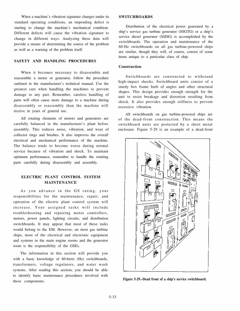
When a machine’s vibration signature changes under its
standard operating conditions, an impending defect is
starting to change the machine’s mechanical condition.Different defects will cause the vibration signature to
change in different ways. Analyzing these data will
provide a means of determining the source of the problem
as well as a warning of the problem itself.
SAFETY AND HANDLING PROCEDURES
When it becomes necessary to disassemble and
reassemble a motor or generator, follow the procedure
outlined in the manufacturer’s technical manual. Use the
greatest care when handling the machines to prevent
damage to any part. Remember, careless handling of
parts will often cause more damage to a machine during
disassembly or reassembly than the machine willreceive in years of general use.
All rotating elements of motors and generators are
carefully balanced in the manufacturer’s plant before
assembly. This reduces noise, vibration, and wear of
collector rings and brushes. It also improves the overall
electrical and mechanical performance of the machine.The balance tends to become worse during normal
service because of vibration and shock. To maintain
optimum performance, remember to handle the rotating
parts carefully during disassembly and assembly.
ELECTRIC PLANT CONTROL SYSTEMMAINTENANCE
A s y o u a d v a n c e i n t h e G S r a t i n g , y o u r
responsibilities for the maintenance, repair, and
operation of the electric plant control system will
i n c r e a s e . Y o u r a s s i g n e d t a s k s w i l l i n c l u d e
troubleshooting and repairing motor controllers,
motors, power panels, lighting circuits, and distribution
switchboards. It may appear that most of these tasks
would belong to the EM. However, on most gas turbine
ships, most of the electrical and electronic equipment
and systems in the main engine rooms and the generatorroom is the responsibility of the GSEs.
The information in this section will provide you
with a basic knowledge of 60-hertz (Hz) switchboards,
transformers, voltage regulators, and water wash
systems. After reading this section, you should be able
to identify basic maintenance procedures involved with
these components.
SWITCHBOARDS
Distribution of the electrical power generated by aship’s service gas turbine generator (SSGTG) or a ship’sservice diesel generator (SSDG) is accomplished by theswitchboards. The operation and maintenance of the60-Hz switchboards on all gas turbine-powered shipsare similar, though they will, of course, consist of someitems unique to a particular class of ship.
Construction
Switchboards are constructed to withstandhigh-impact shocks. Switchboard units consist of asturdy box frame built of angles and other structuralshapes. This design provides enough strength for theunit to resist breakage and distortion resulting fromshock. It also provides enough stiffness to preventexcessive vibration.
All switchboards on gas turbine-powered ships areof the dead-front construct ion. This means theswitchboard units are protected by a sheet metalenclosure. Figure 5-29 is an example of a dead-front
Figure 5-29.–Dead front of a ship’s service switchboard.
5-33

switchboard. Notice that only the meters, operatinghandles, and switches protrude at the front of theswitchboard. Figure 5-30 is an example of the rear of aswi t chboa rd t ha t may be i n s t a l l ed on a ga sturbine-powered ship. The rear of the switchboard isenclosed in expanded metal or solid louvered panels forprotection of personnel. The switchboard may consist ofa single section, or several sections, physically separatedand connected by cables. This sectional arrangementprovides greater protection against damage. For you, asthe technician, it also provides a means for localizingdamage and for removing a damaged section for repairsor replacement.
Maintenance
Several failures of electrical equipment are causedby loose electr ical connect ions and mechanical
fastenings. Loose connections can be readily tightened.
You must first, however, perform a thorough inspection
to detect them.
INSPECTION.– Once a year and during each
ove rhau l , e ach sw i t chboa rd , l oad cen t e r , and
distribution panel should be de-energized for a completeinspection and cleaning. The inspection should not be
limited to a visual examination. It should also include
grasping and shaking electrical connections and
mechanical parts. This lets you make sure that all
electrical connections are tight and that all mechanical
parts are free to functiono
Check the supports of bus work and make sure the
supports will prevent any contact between bus bars of
opposite polarities. Also make sure the supports will
prevent any contact between bus bars and grounded
Figure 5-30.–Rear view of a ship’s service switchboard,
5-34

parts during periods of shock. Be sure to clean both thebus work and the surfaces of the insulating materials.
Check the condition of control wiring and replace itif necessary. Make sure the ventilation of rheostats andresistors is not obstructed. Replace all broken orburned-out resistors. You can make temporary repairsby bridging the burned-out resistors when replacementsare not available. Check all electrical connections fortightness and all wiring for frayed or broken leads.Check all meters for up-to-date calibration tags. Metersare calibrated at a calibration laboratory or on board atender during regular availability. Make sure that allfuses are the right size and that the clips make firmcontact with the fuses.
In addi t ion to the inspect ions we have justdiscussed, make sure (impractical) that switchboards anddistribution panels are de-energized after firing of theguns and inspected for tightness of both the electricalconnections and the mechanical fastenings.
Protect ive circui ts , such as reverse power,undervoltage, or underfrequency circuits, usuallycannot be tested by actual operation because of thedanger involved to the equipment. You should visuallycheck these circuits. When possible, operate these relaysmanually to be certain that the rest of the protectivecircuit performs its intended function. Exercise extremecare not to disrupt vital electrical power service or todamage electrical equipment.
Your inspections should not be confined toswitchboards and distribution panels. Your inspectionsmust also include all adjacent installations that maycause serious casualties. Check the rubber matting in theway of switchboards for signs of deterioration, such ascracks in the material and separations at the seams.
The following examples are installation faults thatcould cause casualties:
1. Ventilation openings located to permit water todischarge onto electrical equipment
2. Insufficient insulation overhead to preventheavy sweating near electrical equipment
3. Missing or inoperative drip-proof covers andspray shields on electrical equipment
4. Location of water piping and flanges whereleakage could spray onto switchboards
T a k e a c t i o n i m m e d i a t e l y t o h a v e t h e s eunsatisfactory conditions corrected.
CLEANING.– You can usually clean bus bars andinsulating materials sufficiently by wiping them with a
dry cloth. You can also use a vacuum cleaner to cleanthe bus bars. Be sure the switchboard or distributionpanel is completely de-energized and remains so untilthe work is completed. Avoid cleaning energized partsand circuits because of the danger to personnel andequipment. Always follow the specified electrical safetyprecautions whenever you are cleaning or workingaround switchboards.
No live contacts are externally exposed on anyswitchboard on a gas turbine ship. You can clean theinsulated front panels of switchboards withoutde-energizing the switchboard. Just wipe them cleanwith a dry cloth. However, you may have to use a damp,soapy cloth to remove grease and fingerprints.Afterward, wipe the surface with a cloth dampened inclear water to remove all soap, and dry it with a clean,dry cloth. Wring out the cleaning cloths thoroughly sono water will run down the front panels. Clean a smallsection at a time and then wipe it dry.
CAUTION
NEVER WIPE A METER FACE WITH A DRYCLOTH. Wiping can cause static electricity to buildup onglass faces and affect meter readings. Breathing on a meterface can help dissipate a charge of static electricity.
Troubleshooting
D u r i n g t r o u b l e s h o o t i n g o f s h i p ’ s s e r v i c eswitchboards, you may have to remove, test, and replacemany parts. Handle these parts with care. Improperhandling of these electrical components can throw offthe alignment of relays and potentiometers. Whenreplacing these components, make sure the parts areplaced back in proper alignment to assure correctoperation. Again, make certain that all applicable safetyprecautions are followed.
Normally, working on energized switchboards isNOT permitted. However, on the occasion when youhave to perform electr ical repair on energizedswitchboards, take the following precautions:
1. Get the approval of the commanding officer.
2. Station safety observers at the switches or circuitbreakers.
3. Demetalize yourself.
4. Wear rubber gloves and boots.
5. Make sure communications are established withall other sources of power that can be secured, if required.
5-35

6. Make sure a person qualified in cardiopulmonaryresuscitation (CPR) is standing by.
On board ship, the most frequent troubles in electricaldistribution systems will be electrical grounds. Frequentand proper use of ground detectors provided on the ship’sservice switchboards and certain power panels will helpyou to locate grounds. When troubleshooting, rememberthe electrical hazards inherent in ungrounded systemsresulting from leakage currents.
T o t e s t a s w i t c h b o a r d f o r g r o u n d s , u s e amegohmmeter (Megger). When preparing to test aswitchboard for grounds, you must first determine ifthere is any low-voltage equipment in the circuit you aretesting. The 500-volt output of the Megger coulddamage the components in these circuits. Sincetransistors, diodes, capacitors, and some rectifiers canbe damaged by the high output of the Megger, they mustbe removed or short-circuited before you start testingfor grounds.
TRANSFORMERS
A transformer transfers energy from one circuit toanother by electromagnetic induction. This energy isalways transferred without a change in frequency. It is,however, usually transferred with a change in voltageand current. Transformers are found in many circuitsand components maintained by GSEs. You mustunderstand their construct ion and operat ion toeffectively troubleshoot and repair them.
Construction
The typical transformer has two windings insulatedelectrically from each other. These windings are woundon a cylindrical or rectangular cardboard form. In effect,the core material is air and the transformer is called anAIR-CORE TRANSFORMER. Transformers used atlow frequencies, such as 60 Hz, require a core oflow-reluctance magnetic material, usually iron. Thistype of t ransformer is cal led an IRON-CORETRANSFORMER. In its most basic form, a transformerconsists of four parts. As shown in figure 5-31, thesefour primary parts and their functions areas follows:
1. A core, which provides a low-reluctance path forthe magnetic lines of flux
2. A primary winding, which receives energy fromthe ac source
3. A secondary winding, which receives energyfrom the primary winding and delivers this energy to theload
4. An enclosure, which protects a l l of thecomponents from dirt, moisture, and mechanicaldamage
When a transformer is used to step up the voltage,the low-voltage winding is the primary winding.Conversely, when a transformer is used to step down thevoltage, the high-voltage winding is the primarywinding. The primary winding is always connected tothe source of power. The secondary winding is alwaysconnected to the load.
Maintenance
The power-handling capacity of a transformer isdependent upon its ability to dissipate heat. If the heatcan safely be removed, the power-handling capacity ofthe transformer can be increased. The heat built up in atransformer can be high enough to cause the insulationaround the wire to break down. If this happens, thetransformer may be permanently damaged. To helpprevent this condition, a thorough inspection andcleaning of a transformer is necessary.
INSPECTION.— Periodically, each transformershould be de-energized for a complete inspection andcleaning. Since there are no moving parts intransformers, inspection is a simple task. This inspectionshould not, however, be limited to a visual examination.You should check the electrical connections forlooseness by grasping and shaking them.
There is one inspection you can perform while thetransformer is energized. As a competent technician,you should be constant ly on the look out fortransformers that are operating excessively hot. Take theproper corrective action quickly to prevent anypermanent damage to the transformer.
C L E A N I N G . — Dirty windings or cloggedventilation ports will usually cause a transformer tooperate hotter than normal. When you notice atransformer that is operating excessively hot, makeplans to have it secured and cleaned. YOU can usuallysufficiently clean transformers by wiping them with adry cloth. Be sure all transformers are completelyde-energized and isolated and remain so until the workis completed. Always follow all electrical safetyprecautions when you clean transformers.
Troubleshooting
Transformers are usually trouble-free. Becauset r a n s f o r m e r s n o r m a l l y d o n o t m a l f u n c t i o n ,t roubleshoot ing should be a s imple task. Since
5-36

Figure 5-31.—Basic parts of a single-phase transformer.
transformers have no moving parts, only electricalmalfunctions will occur. The windings can becomeshort-circuited, grounded, or open-circuited. Thetroubleshooting techniques you should use to isolatethese problems are the same as those you would use forany other electrical component. When taking readingson the primary and secondary windings of a transformer,make sure the windings are isolated from other circuits.This precaution will help you to eliminate errors in yourreadings.
Once again, observe the standard safety precautionswhen working on transformers.
WARNING
Always wear safety goggles. The cooling liquidsused in transformers could damage your eyes if thetransformer should overheat and explode.
Keep a cool head and think about the possibleconsequences before you perform any act ion.Carelessness is the cause of most accidents. Rememberthe best GSE is not necessarily the fastest one, but theone who will be on the job tomorrow.
VOLTAGE REGULATORS
The voltage regulators used on gas turbine-poweredships differ in type and design. The auxiliary equipmentused with each voltage regulator may also differ in type,function, and design. Because of these differences, noattempt will be made in this TRAMAN to describe indetail the construction, operation, care, and maintenanceof each type of voltage regulator. The followingdiscussion will be limited to general information thatwill provide you with some basic guidelines in the careand maintenance of voltage regulators.
Always refer to the applicable technical manuals fora detailed description of the construction, operation,care, and maintenance of any particular voltageregulator. You should be thoroughly acquainted with thecontents of the technical manual and with theinformation contained in this section.
A voltage regulator consists of a control element andthe associated mechanical or electrical means toproduce the changes in the generator field current. Thesechanges are necessary to maintain a predeterminedconstant generator terminal voltage. The function
5-37

performed by voltage regulators and their auxiliaryequipment is to keep the generator terminal voltagewithin specified limits. The voltage regulator alsoprovides for proper division of the reactive currentbetween generators operating in parallel.
If you consider all the possible combinations oftypes of voltage-sensitive elements and their associatedcontrol means, you can visualize why there are so manydifferent types of voltage regulators. The two types usedspecifically on gas turbine-powered ships are the
static exciter and electronic voltage regulator,and the
rotating brushless ac exciter with electronicvoltage regulator.
We will briefly discuss each of these types.
Static Exciter Voltage Regulator
The static exciter voltage regulator system suppliesdc current to the ac generator field by rectifying a partof the ac generator output. The voltage detector consistsof a network of capacitors, reactors, and resistors. Itcontrols the power input to the generator field bymagnetic amplifiers or silicon controlled rectifiers(SCRs).
This type of voltage regulator system is found onthe DD-963, DDG-993, and FFG-7 class ships. Thevoltage regulator on the DD-963 and DDG-993 classships is located in the generator control unit (GCU) forthe associated generator. The GCU is mounted near eachassociated switchboard. The voltage regulators on theFFG-7 class ships are located in cabinets in the auxiliarymachinery rooms (AMRs) and in the switch gear room.
Brushless AC Exciter Voltage Regulator
The brushless ac exciter voltage regulator systemcontrols the dc power delivered to the stationary field ofa brushless exciter. Its rotating armature ac output isrectified by SCRs mounted on or in its shaft. Theregulated dc power is connected directly to the maingenerator field. This statically controlled rotatingsystem is brushless, having no commutators or sliprings. Because of this design, measurement of maingenerator field voltage and current is not practical.
This type of voltage regulator is found on the CG-47class ship and is located in the GCU mounted near eachassociated switchboard. The voltage regulator on theDDG-51 class ship is located in the exciter control panel(EXCOP).
Maintenance
V o l t a g e r e g u l a t o r s y s t e m s o n b o a r d g a sturbine-powered ships are maintained by PMS.Remember to refer to the appropriate manufacturer’stechnical manuals for detailed instructions concerningthe maintenance of voltage regulators. You can,however, use the following general instructionswhenever you are performing maintenance on anyvoltage regulator:
1 . M a k e s u r e a l l c o n n e c t i o n s t o t h evoltage-sensitive element and those between theelement and all the auxiliary equipment are tight. Theseconnections should be exactly as specified in themanufacturer’s wiring diagram.
2. Make all necessary adjustments according to themanufacturer’s technical manual.
3. Make sure all contacts are clean and free fromgrease, dirt, or other foreign material.
4. Make sure all brushes, relays, contractors,damping devices, and motor-operated potentiometersmove freely and smoothly. Make sure these componentsare unobstructed by any foreign material.
5. See that the connections to the contacts of thevoltage-sensitive element and relays give the correctdirection of rotation to the pilot motor of the fieldrheostat.
6. Make sure the contact arm of the motor-operatedfield rheostat moves smoothly over its entire range. Thismovement should be at the same speed up and down,when driven by the pilot motor or when operated byhand.
7. Check the limit switches to see that they functionproperly to disconnect the pilot motor from the linewhen they are tripped by the contact arm.
8. Make sure the pilot motor is clean and free fromcracks, chips, and obstructions. Check the motor forsigns of overheating.
Troubleshooting
When troubles develop in voltage regulators, youmust locate the faulty component, remove it, and replaceit with a new one. Once again, you should use themanufacturer’s technical manual to isolate the troubles.R e m e m b e r , y o u s h o u l d c o n s i d e r t h e c o m m o nmalfunctions we will discuss in the next paragraph assupplemental information to the specified malfunctions
5-38

and corrective actions in the appropriate technicalmanual.
When a voltage regulator is not operating properly,you must observe the symptoms provided to you. Youmust know what the unit is supposed to do before you
can determine what it is not doing or what it is doingincorrectly. The following list contains several commonmalfunctions that occur in voltage regulators:
Open circuits in leads to and from the rectifierassembly
Open circuits between the exciter field and theregulating resistance
Short circuits of the regulator terminals
Obstructions in any of the moving parts
Loose or faulty connections in various circuits
Binding or function in the pilot motor assembly
Friction in the moving parts of relays or rheostats
Dirt, grease, or other foreign materials on the
contacts of relays or rheostats
Faulty diodes, transistors, capacitors, and othersmall electronic components
Misalignment of the gears, screw, or rod of themotor-operated potentiometer assembly
During troubleshooting, you can loosen many of theconnections to perform various tests. You can alsoremove and replace several parts during these tests.
A voltage regulator is a very sensitive piece ofequipment. You must make sure to handle its parts withcare. The alignment of limit switches, control relays, andmotor-operated potentiometers can be thrown off byimproper handling. When replacing these components,
make sure to place the parts back in proper alignment toensure correct operation. Make sure you use the correctsoldering and resoldering techniques. (Sometimes,more harm than good is done by use of impropersoldering techniques.)
You must also use extreme care when tagging outthe voltage regulator for maintenance. Most voltageregulators have multiple sources of power. When
securing power to the voltage regulator, make sure youinvestigate your ship’s particular system. Finally, be
certain you follow all applicable electrical safetyprecautions whenever you are performing maintenance
and repair on voltage regulators.
WATER WASH SYSTEM
A water wash system is a maintenance featureprovided to remove dirt, salt, or other foreign depositsfrom the internal parts of a gas turbine. Water washingis accomplished by spraying a mixture of distilled waterand cleaning agent into the compressor while the gasturbine is motoring. Rinsing is done in the same manner,using distilled water only.
A water wash system is found on the LM2500 GTEfor the DD-, DDG-, CG-, FFG-, and PHM-class ships.It is also found on the Allison gas turbine generators onthe DD-, DDG-, and CG-class ships. The LCACs havea water wash system on Lycoming TF40B main enginesand the Sunstrand T-62T auxiliary power unit. ThePHMs also have a water wash system on the Garrettship’s service power unit.
T h e w a t e r w a s h s y s t e m o n e a c h g a sturbine-powered ship is unique in its own design.Although many different types of components are foundin each design, the following electrical components arec o m m o n t o m o s t w a t e r w a s h s y s t e m s o n g a sturbine-powered ships:
Level switches
Solenoid-operated valves
ON/OFF water wash toggle switches
TANK EMPTY indicators
Heaters
Magnetic controllers.
We will briefly discuss the maintenance andt r o u b l e s h o o t i n g t e c h n i q u e s f o r t h e s e c o m m o ncomponents.
Maintenance
You can accomplish the maintenance procedures forthe components of your ship’s water wash system byusing the basic procedures we have already covered inthis chapter. Like other systems, the water wash systemmust be periodically inspected and tested. Failure isoften caused by loose electrical connections andinoperative solenoid valves. The keys to maintaining at r o u b l e - f r e e w a t e r w a s h s y s t e m a r e t h o r o u g hinspections and tests.
INSPECTION.— The gas turbine engine should bewater washed according to PMS. During PMS, thesystem should be inspected according to the MRC. The
5-39

inspection should not be limited to a visual examination,but also should include checking for loose electricalconnections and mechanical parts.
Check the condition of control wiring to thesolenoid valves and replace it if necessary. Check allelectrical connections for tightness and all wiring forfrayed or broken leads. Check the printed circuit cardfor signs of overheating around the resistors.
TESTING.– Testing the water wash system shouldalso be accomplished through PMS. In fact, thecomponents of the system should be tested during awater wash cycle. As a GSE, you will be looking for anysigns of electrical trouble. If you are called upon toinvestigate a problem with the water wash system, youmust understand how the system operates. Thisknowledge will help you to cut down maintenance time.
Troubleshooting
Troubleshooting the water wash system presents nonew techniques. Earlier in this chapter we discussed theprocedures you should use to troubleshoot and repairmany of the components of the water wash system, suchas the solenoids, microswitches, and controllers. In thefollowing paragraphs, we will limit our discussion to theprocedures you will use to maintain and repair levelswitches (float switches) and heaters.
LEVEL SWITCHES.– Level switches are used inwater wash systems of gas turbines for different reasons,depending on the system installed. On FFG-7 classships, there are three level switches in the water washtank One switch provides a high-level signal for logiccircuits in the propulsion control system (PCS). Anotherswitch provides a low-level signal for the logic circuitsin the PCS. The other switch controls the energizing ofthe tank heater. On the DD-, CG-, and DDG-class ships,one level switch is installed in the water wash system.This switch provides a signal to illuminate the waterwash TANK EMPTY indicator lights at the localconsole. The LCAC system also has one level switch. Itis located in the supply tank and provides a FULLindication at the fill connection.
Most f loats used inside the wash tanks aremaintenance-free. The switch contacts are sealed insidea bell-shaped float. A wire extends out of the top of thefloat to allow for connection to the circuits. As the floatrises and tips over, the contacts close, completing thecircuit to the water wash system’s electronics. If the floatfails to operate, you must gain access to the float toreplace it.
5-40
To test the float, first drain the wash tank. Then openthe access cover to remove the float from the tank. Ofcourse, you must fol low al l applicable safetyprecautions, including those for tagging the system outof service and securing the electrical power. Next, usingan ohmmeter, tip or raise the float while reading theresistance value at the connections. If there is no changein the resistance, the switch in the float is faulty. Sincethe contacts are sealed inside the float, you cannot repairthe switch. You must, therefore, remove and replace thefloat.
HEATERS.– A heater is located in the wash tank ofthe FFG-7 class water wash system. It is used to heat thewater wash solution (if required). You can energize theheater by depressing the ON push button on the heater’smagnetic controller.
Troubleshooting the heater is a simple task for aGSE. Just take a resistance reading on the input leads tothe heater. Refer to the manufacturer’s technical manualto find the correct ohmic value for the heater. If thereading is within tolerance, check the magneticcontroller for a fault. Use the maintenance andtroubleshooting procedures for magnetic controllers wediscussed earlier in this chapter.
POWER SUPPLIES
In today’s Navy, all electronic equipment requiressome form of power supply. On gas turbine-poweredships, the electronic control consoles contain manypower supplies . Although the appearance andconstruction of these power supplies may differ, thebasic operation is the same. In this section, we willdiscuss the components and the operation of a basicpower supply. We will also discuss the maintenance andtroubleshooting techniques involved with powersupplies.
It is beyond the scope of this TRAMAN to try todiscuss all types of power supplies used on gasturbine-powered ships. The differences are tooabundant; therefore, we will discuss only the commonpoints of interest. For a more detailed description, referto the technical manual that applies to your ship’sequipment.
BASIC POWER SUPPLY
Most power supplies are made up of four basicsections: a (1) transformer, (2) rectifier, (3) filter, and(4) regulator. Study figure 5-32, which shows the blockdiagram of the basic power supply.
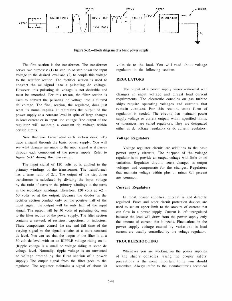
Figure 5-32.—Block diagram of a basic power supply.
The first section is the transformer. The transformer
serves two purposes: (1) to step up or step down the inputvoltage to the desired level and (2) to couple this voltageto the rectifier section. The rectifier section is used toconvert the ac signal into a pulsating dc voltage.However, this pulsating dc voltage is not desirable andmust be smoothed. For this reason, the filter section isused to convert the pulsating dc voltage into a filtereddc voltage. The final section, the regulator, does justwhat its name implies. It maintains the output of thepower supply at a constant level in spite of large changesin load current or in input line voltage. The output of theregulator will maintain a constant dc voltage withincertain limits.
Now that you know what each section does, let’strace a signal through the basic power supply. You willsee what changes are made to the input signal as it passesthrough each component of the power supply. Refer tofigure 5-32 during this discussion.
The input signal of 120 volts ac is applied to theprimary windings of the transformer. The transformerhas a turns ratio of 2:1. The output of the step-downtransformer is calculated by dividing the input voltageby the ratio of turns in the primary windings to the turns
in the secondary windings. Therefore, 120 volts ac ÷2 =60 volts ac at the output. Because the diodes in therectifier section conduct only on the positive half of theinput signal, the output will be only half of the inputsignal. The output will be 30 volts of pulsating dc, sentto the filter section of the power supply. The filter sectioncontains a network of resistors, capacitors, or inductors.These components control the rise and fall time of thevarying signal so the signal remains at a more constantdc level. You can see that the output of the filter is at a30-volt dc level with an ac RIPPLE voltage riding on it.
(Ripple voltage is a small ac voltage riding at some dcvoltage level. Normally, ripple voltage is an unwantedac voltage created by the filter section of a powersupply.) The output signal from the filter goes to theregulator. The regulator maintains a signal of about 30
volts dc to the load. You will read about voltageregulators in the following sections.
REGULATORS
The output of a power supply varies somewhat withchanges in input voltage and circuit load currentrequirements. The electronic consoles on gas turbineships require operating voltages and currents thatremain constant. For this reason, some form ofregulation is needed. The circuits that maintain powersupply voltage or current outputs within specified limits,or tolerances, are called regulators. They are designatedeither as dc voltage regulators or dc current regulators.
Voltage Regulators
Voltage regulator circuits are additions to the basicpower supply circuits. The purpose of the voltageregulator is to provide an output voltage with little or novariation. Regulator circuits sense changes in outputvoltages and compensate for the changes. Regulatorsthat maintain voltage within plus or minus 0.1 percentare common.
Current Regulators
In most power supplies, current is not directlyregulated. Fuses and other circuit protection devices areused to set an upper limit to the amount of current thatcan flow in a power supply. Current is left unregulatedbecause the load will draw from the power supply onlythe amount of current that it needs. Fluctuations in thepower supply voltage caused by variations in loadcurrent are usually controlled by the voltage regulator.
TROUBLESHOOTING
Whenever you are working on the power suppliesof the ship’s consoles, using the proper safetyprecautions is the most important thing you shouldremember. Always refer to the manufacturer’s technical
5-41

manual when you are preparing to adjust powersupplies. Before starting work on any electronicequipment, always make sure the equipment is properlygrounded. Also make sure the rubber matting you arestanding on is in good condition.
Although the power supplies for the consoles aremore sophisticated than the one described in this section,the troubleshooting principles are the same. Many of thepower supplies on gas turbine ships have LEDs to showwhen the output of the power supply is out of limits.Usually, one LED indicates high output voltage andanother LED indicates low output voltage. There maybe still another LED that indicates a fault has occurredin the power supply. Remember, you must refer to theappropriate technical manual to understand what causeseach LED to light.
TESTING
In testing electronic power supplies, there are twowidely used methods you will use: (1) visual check and(2) signal tracing. Because you will use both of thesemethods to test and maintain your ship’s power supplies,we will describe the procedures for each of thesemethods, starting with the visual check.
Visual Check
The importance of the visual check should not beunderestimated because many GSEs can find defectsright away simply by looking for them. A visual checkdoes not take long. In fact, you should begin to see theproblem in about 2 or 3 minutes, if it is the kind ofproblem that can be seen.
When visually checking power supplies, you shoulduse the procedures described in the next paragraph. Youwill find yourself using this method often, as it is goodnot only for power supplies but also for any other typeof electronic equipment.
Before you install any power supply in a console orelectronic enclosure, look for the following problems:
1. SHORTS–Examine any terminal or connectionthat is close to the chassis or to any other terminal forthe chance of a short. A short in any part of the powersupply can cause major damage. Look for and removeany stray drops of solder, bits of wire, nuts, or screws.It sometimes helps to shake the power supply moduleand listen for any tell-tale rattles.
2 . A D I S C O L O R E D O R L E A K I N GTRANSFORMER—This is a sure sign there is a shortsomewhere in the power supply circuits. If the
5-42
equipment has a fuse, find out why the fuse did not blow.See if the correct size fuse is installed. Also make surethere is not a short across the fuse holder.
3. LOOSE, BROKEN, OR CORRODED CON -NECTIONS– Any connection that is not in goodcondition is a trouble spot. If it is not causing you troubleat the present, it will probably cause problems in thefuture.
4 . DAMAGED RESISTORS OR CAPACI -TORS— A resistor that is discolored or charred has beensubjected to an overload. An electrolytic capacitor willshow white deposits at the seal around the terminals.Whenever you notice a damaged resistor or capacitor,check for a short. Make a note to replace the damagedor faulty part after you have performed your signaltracing procedures. There is no sense in risking a newpart until the trouble is located.
After you install a power supply, apply power to theconsole or the electronic enclosure and look for thefollowing defects:
1. SMOKING PARTS— If any part smokes, or ifyou hear any boiling or sputtering sounds, power the unitdown immediately. Somewhere there is a short circuityou have missed in your first inspection. Use anohmmeter to check the power supply once again. It is agood idea to begin in the area of the smoking part.
2. SPARKING— Tap or shake the power supply. Ifyou hear or see any sparking, you have located a looseconnection or short. Once again, check the power supplyand repair it.
If you locate and repair any of these defects, makea note of what you find and what you plan to do to correctit. It is likely you have found the trouble. However, agood GSE takes nothing for granted. You must prove toyourself that the equipment is operating properly andthat no other troubles exist.
If you do not find any of the defects we have justdiscussed, go ahead with the second check used intesting: signal tracing. The problem is something youcannot see directly with your eyes. You must view itthrough the eye of your test equipment.
Signal Tracing
Tracing the ac signal through the power supply isthe most rapid method you can use to locate trouble youcannot find by a visual check. It is helpful to use anoscilloscope when you are testing power supplies. Theidea is to trace the ac voltage from the transformer, tosee it change to pulsating dc at the rectifier section, and

then to see the pulsations smoothed out by the filter. Thepoint where the signal stops or becomes distorted is theplace you should look for trouble.
Before you begin signal tracing, it is a good idea tomeasure the dc voltage. If you have no dc output voltage,you should look for an open or a short in your signaltracing. If you have low dc voltage, you should look fora defective part. Keep your eyes open for the placewhere the signal becomes distorted.
No matter what power supplies you may comeacross on the various classes of gas turbine-poweredships, they all do the same thing. They change ac voltageinto usable dc voltage(s). For that reason, basictroubleshooting and testing will be the same. Althoughyou may experience problems that have not beencovered specifically in this section, you should havegained enough knowledge to localize and repair anypower supply problem that may occur.
ADJUSTMENTS
Many console power suppl ies contain dc/dcconverters that require adjustment of their output levels.The adjustment variable resistor and the test points formonitoring converter output are accessible when thepower supply cover is removed. An example of a dc/dcconverter with test points, fault LEDs, and an outputadjustment resistor is shown in figure 5-33.
Power supplies contain different types of de/deconverters. These converters vary only in theirdevelopment of different outputs. The procedures foradjusting each converter will differ only in thespecification of the output level. When adjusting theconverters of console power supplies, make sure theyare under normal load conditions. Some power supplyconverters are wired in parallel pairs. Adjust these byalternately securing the power to one power supply,while adjusting the other.
PUMP LOGIC CALIBRATION
One important and frequently performed task of theGSE is to make sure the fuel oil and lube oil pumps cycleas designed. This action is called pump logic calibration.Pump logic calibration is accomplished according toPMS. As a GSE, you must be able to recognize andcorrect any malfunctions that occur with pump logic.Your actions will help keep the engineering plantoperating at its maximum efficiency.
Each gas turbine-powered ship has different pumplogic settings. These differences are too numerous forus to cover in this TRAMAN. In this section, however,we will discuss the basic elements of pump logiccalibration. Remember, refer to the appropriatetechnical manual for detailed descriptions of the propersettings for fuel oil and lube oil pumps.
PUMP LOGIC FUNCTION
During normal operation, the fuel oil booster pumpsand lube oil pumps are automatically cycled by pumpcontrol logic. They are cycled between off, slow, andfast to maintain header pressure. Pump control logic willcontrol the pumps to increase header pressure when
pump output is inadequate to meet demand.
The cycling characteristics and pressures differ oneach class of ship. Fuel oil pump control logic preventsloss of fuel to the gas engines by cycling the pump (orpumps) up to fast when the pressure drops. Sometimes,fuel pump control logic cycles both pumps to stop ifpressure does not recover after a determined number ofseconds. This action prevents flooding of the engineroom if a fuel leak develops.
On some ships, the fuel pumps must be slowed orstopped manually. Lube oil pump control logic preventsreduction gear damage by constantly providing positivelube oil pressure to the gear. Pump logic usually cyclesthe lube oil pumps up and down with respect to lube oilpressure.
Figure 5-33.—Power supply dc/dc converter.
5-43

PUMP LOGIC TESTING
Testing the pump logic circuits is usuallyaccomplished with PMS. The MRC gives youstep-by-step instructions on how to set up your fuel oiland lube oil system to complete the test. You accomplishthe test by disconnecting the transducer input from thesystem and hooking up a gauge comparator to thetransducer. The comparator will simulate systempressure. Next, you pump up the comparator to reachnormal system pressure, and then decrease the pressureto a predetermined level. Maintain this level for arequired number of seconds, after which the pump orpumps will shift speed to maintain pressure. You arechecking to see if the pump or pumps will shift up ordown within the required time frame. You shouldcontinue this procedure until all specific operatingpoints are tested. After completing the test, return thesystem to its normal configuration. If the test is notsatisfactory, you will have to start troubleshooting tofind the problem.
PUMP LOGIC TROUBLESHOOTING
When a console operator experiences a problemwith pump logic, he or she will contact you, the GSE.One of your first steps in troubleshooting pump logiccircuits is to open the console and check for any faultLEDs that may be lit. Examination of the circuit cardswith lighted LEDs will be your next logical step. Uponidentifying a malfunctioning circuit card, refer to theproper troubleshooting diagram to identify the faultedarea.
If there are no faulted circuit cards, you will have todetermine if a problem exists. If the ship is underwayand the system has to be on line, you can not actuallywork on the problem. While waiting to work on thesystem, take the opportunity to look at how the systemis operating under normal conditions. Take notes on howthe system is functioning. Your notes should includepressures, times, and system configuration. Whensystem operation is no longer required, you can use thegauge comparator to duplicate those conditions. Usingthe PMS card, test the pump logic circuits. If the testfails, you will need to refer to the manufacturer’stechnical manual.
There are several reasons the pump control logiccould malfunction. The following list contains some ofthe problems that can cause the pump control logic tofall:
Malfunctioning magnetic controller
5-44
Faulty pump
Faulty pump control logic card
Faulty delay timer or time control card
Faulty relay driver card or relay actuator
Malfunctioning switches
If the problem lies within a particular console, you
must take certain procedural steps to locate the faulty
subassembly or circuit card. Use the following steps to
troubleshoot console equipment malfunctions:
1. Energize the console and related equipment for
troubleshooting.
2. Identify the faulting fictional area.
3. Refer to the technical manual to locate the signal
flow diagram that relates to the faulting functional area.
4. Using the proper troubleshooting diagram,
isolate the malfunction to the faulting subassembly or
circuit card.
5. When you have isolated the fault to a particular
circuit card or subassembly, perform corrective
maintenance by replacing the faulty part.
When troubleshooting the pump control logic
circuits, always use proper troubleshooting techniques
and follow all applicable electrical safety precautions.
PROPULSION SYSTEM
MAINTENANCE
Most maintenance tasks for the GSE will involve
console upkeep and maintenance. The GSE must
remove and replace various parts of the engineering
plant consoles. Each gas turbine-powered ship has
several control consoles, each with its own technical
manual.
In this section, we will discuss the procedures you
will use to perform maintenance on the consoles of
several different classes of ships. The basic maintenance
techniques are the same throughout the GSE rating. An
extensive discussion of the maintenance required on
control consoles is beyond the scope of this TRAMAN.
Therefore, the procedures described in this section are
basic in nature. Refer to the proper console technical
manual for a detailed description of the maintenance
required on your particular propulsion control consoles.

FUEL SYSTEM CONTROL CONSOLE
The FSCC is located in the CCS of DD-963,DDG-993, and CG-47 class ships. This consoleprovides operator control and monitoring of the ship’sfuel storage and transfer system. Maintenance of thisconsole is the responsibility of the GSEs.
FSCC Testing
Testing the FSCC is a task you, the GSE, mustperform daily. The daily tests consist of a hazard alarmtest, fault alarm test, and lamp test.
You will use the hazard alarm test to make sure thehazard alarm circuits are functioning properly. Start thehazard alarm test by depressing the HAZARD ALARMTEST push button on the FSCC. This action will causeeach hazard alarm circuit to start a hazard alarm,consisting of a 4-Hz flashing light and a 4-Hz tone.
You will use the fault alarm test to make sure thefault alarm circuits are functioning properly. Start thefault alarm test by depressing the FAULT ALARMTEST push button on the FSCC. This action will causeeach fault alarm circuit to start a fault alarm, consistingof a 1-Hz flashing light and a 1-Hz tone.
The last daily test you must perform on the FSCCis the lamp test. Start the test by depressing the LAMPTEST push button on the FSCC. This action will causeall the indicator lights not checked by the alarm tests tolight steadily, allowing you to locate burned out lampson the console.
You will also test the meters on the FSCC, but notdaily. In these tests, you must use the calibrate panel onthe back of the FSCC. You will usually calibrate thesemeters before refueling and during PMS. You will usethe calibrate panel to accomplish calibration of thestorage tank level meters, the receiving tank pressuremeters, and the high seawater and fuel overflow alarms.
FSCC Maintenance
Most of the maintenance required on the FSCC willstem from the failure of one of the tests we have justdescribed. If an indicator fails to light or a meter fails torespond correctly, you must find the cause of the failure.Always refer to the manufacturer’s technical manualwhenever you perform maintenance on the FSCC.
When you are trying to locate a problem, there areseveral circuits in the FSCC you must investigate. Thereare a total of 32 printed circuit boards (PCBs) used inmonitoring, alarm, and control functions. The FSCC
also has eight power supplies located in the powersupply drawers. Maintenance of power supplies wasdiscussed earlier in this chapter.
TANK LEVEL MONITORING AND ALARMGENERATION.— One area of the FSCC that youshould give particular attention is the tank levelmonitoring and alarm circuits. Individual tank levels aredisplayed by vertical panel meters. The tank levelcircuits convert analog information from a tank leveltransmitter to a meter display. Some of the circuits haveassociated hazard alarms for high- or low-levelconditions.
Tank Level Transmitters.— Each level-monitoredtank has a level transmitter. A typical transmitter sectionhas a voltage divider resistor network extending thelength of the section. Magnetic reed switches are tappedat 1-inch intervals along the resistor network. The reedswitches are sequentially connected through seriesresistors to a common conductor. This network isenclosed in a stem that is mounted vertically in the tank.Afloat with bar magnets rides up and down the stem asthe level changes.
Tank Level Monitoring Circuits.— Refer to the
typical tank level monitoring circuit shown in figure5-34. The signal from the level transmitter is sent to alevel monitoring circuit in the FSCC. This circuit, inturn, drives the associated panel meter(s) and starts thevisual and audible indications for a hazard alarm. Thiscircuit also provides sensor circuit fault indication andmeter and alarm calibration.
PRESSURE MONITORING AND ALARMGENERATION.— Another important area of the FSCCis the pressure monitoring and alarm generation circuits.Pressure is monitored and displayed for the fuel oilreceiving tanks, transfer pump inlets and discharges, andpurifier inlets and discharges. All but the purifier inletshave HIGH PRESS hazard alarms. These circuits are allfunctionally similar.
Pressure Transducers.— Pressure transducers aresupplied with +24 volts dc. They regulate current flowbetween this +24 volts and common so that the currentremains regulated proportional to the pressure input.The current is varied from 4 to 20 milliamps (mA) asthe pressure changes from the low extremity of its rangeto the maximum. Current regulation is accomplished bycircuits located within the transducer.
Pressure Monitoring Circuits.— Study the typical
pressure monitoring circuit shown in figure 5-35. Thepressure signal from the pressure transducer is sent to apressure monitoring circuit in the FSCC. This circuit
5-45

Figure 5-34.—Typical tank level monitoring circuit.
Figure 5-35.—Typical pressure monitoring circuit.
5-46

provides meter calibration, starts hazard alarms, and
provides alarm point adjustment. It also gives fault
condition indication.
TEMPERATURE MONITORING.– The final
area that should be given attention is the temperature
monitoring circuits. A typical temperature monitoring
circuit is shown in figure 5-36. Temperature of the fuel
oil discharge from the two fuel oil transfer heaters is
monitored by this system. This temperature is displayed
at the FSCC by a vertical meter. The meter circuitry is
located in the fuel oil local control panels.
Temperature Sensors.– The temperature for the
fuel oil is sensed by a resistance temperature detector
(RTD). Associated with each RTD is a s ignal
conditioner. It uses system 24 volts dc to regulate a 4-
to 20-mA output at a value proportional to the RTD
resistance.
Temperature Moni tor ing Circu i t s . – T h e
monitoring circuit for fuel oil heater No. 1 is located in
fuel oil transfer local panel No. 1. The circuit for fuel oil
heater No. 2 is located in local panel No. 2. Each circuit
has a remote display at the FSCC.
Since the temperature signal from the signal
conditioner is at a 4- to 20-mA level, it is routed through
the PUSH TO SET FULL SCALE switch to the panel
meters. A mode switch allows selection of LOCAL AND
REMOTE or LOCAL ONLY displays. The meter
current return is through a fixed resistor to -5 volts.
When the PUSH TO SET FULL SCALE pushbutton is depressed, a 20-mA signal is routed from themeter circuit board to the meter. You can adjust frill scaleby using the mechanical full scale adjust screw on themeter.
When testing and performing maintenance on theFSCC, always follow the applicable electrical safetyprecautions. Use common sense when troubleshootingthe console. It is not good practice to test, troubleshoot,or repair the console circuits while refueling ortransferring operations are in progress. This is becausethe chance of damaging equipment or spilling fuel isincreased during maintenance procedures.
PROPULSION AND AUXILIARY CONTROLCONSOLE/PROPULSION CONTROLCONSOLE
The propulsion and auxiliary control console(PACC) is located in the CCS of DD-963, DDG-993,DDG-51, and CG-47 class ships. On FFG-7 class ships,this console is called the propulsion control console(PCC) and is also located in the CCS. These consolesprovide operator control and monitoring of the ship’smain propulsion system. Ships that have the PACC alsohave the capability of monitoring and controlling someof the auxiliary systems. The PACC and PCC are themost carefully monitored consoles while the ship isunderway. Therefore, improper operation of theseconso le s i s immed ia t e ly no t i ced . As a GSE,
Figure 5-36.—Typical temperature monitoring circuit.
5-47

main t enance o f t he PACC and PCC i s you rresponsibility.
PACC and PCC Testing
Daily testing of the PACC and PCC is normally
performed by the console operator. On the PACC onDD-, DDG-, and CG-class ships, the daily tests consistof a audible test of the bell, horn, and siren. An audibletest of the buzzer is included on the PACC on theDDG-51 class ship. The PACC and the PCC have lamptest circuits for testing the indicator lamps and LEDs.
You will use the audible alarm tests to make sure theaudible alarm circuits are functioning properly. To startthese tests, depress the appropriate test push button onthe PACC. This action will cause each audible alarmcircuit to sound an audible alarm.
The lamp test is conducted by depressing a LAMPTEST push button or activating the STATUS/ALARMswitch on the PACC or PCC. This action will cause allthe alarm and status lights to illuminate on thedesignated section, allowing you to locate the burnedout lamps on the console.
PACC and PCC Maintenance
The PACC and PCC are complex electroniccomponents. However, the basic troubleshooting andmaintenance procedures used throughout your ratingwill still apply. Control and other electronic circuitry ispackaged on circuit card assemblies located in cardracks inside the consoles. Each circuit card is assignedits own designation to ease troubleshooting. The PACCand PCC also contain power distribution circuits andfuses.
Some of the maintenance required on the PACC orPCC will stem from the failure of one of the tests wehave just described. If an indicator fails to light, youmust find the cause of the failure. Most problems thatoccur to the PACC or PCC will happen during normaloperation of the engineering plant. Imagine, forexample, that during a GTE start, the main fuel valvefails to open. You, as the GSE, are called to investigatethis problem. Always remember to refer to themanufacturer’s technical manual when you are planningto perform maintenance on the PACC and PCC.
When a problem or fault occurs in the PACC or thePCC, you must know where to start troubleshooting.Using the technical manuals is essential in this step. ThePACC and PCC contain so many circuits that it would
5-48
be impossible for you to start your troubleshootingefforts without referring to the technical manual.
To use the technical manual correctly, however, youmust first know what particular major circuit function isaffected. A major circuit function area is a collection ofcircuits that are designed to achieve a certain function,such as starting a GTM, monitoring start air valve status,and so forth. Examples of major function areas in thePACC and PCC are as follows:
Main reduction gear (MRG) monitoring andcontrol circuits
CRP/CPP monitoring and control circuits
Fuel oil service monitoring and control circuits
Lube oil service monitoring and control circuits
Gas turbine module (GTM) monitoring andcontrol circuits
Air control and monitoring circuits
Recognizing and understanding the major functionareas of the PACC and PCC will ease your maintenanceand troubleshooting efforts.
ELECTRIC PLANT CONTROL CONSOLE
The electric plant control console (EPCC) is locatedin the CCS of DD-963, DDG-993, DDG-51, CG-47, andFFG-7 class ships. This console provides the operatorwith automatic and manual controls, displays ofperformance parameters, status indications, and alarmindications for remote operation of the ship’s electricplant. Controls are provided for generator start/stop,generator paralleling, voltage and frequency raise/lowerfunctions, and circuit breaker close/trip functions. Logicis provided for continuous monitoring of the electricplant operating configuration and supplying electricplant status information. The EPCC is continuouslymonitored while the ship is underway. Any malfunctionof the console is immediately noticed. As a GSE,maintenance of the EPCC is also your responsibility.
EPCC Testing
Daily testing of the EPCC is normally performed bythe console operator. The EPCC logic on some shipsperforms self tests at set intervals. The daily tests on theEPCC consist of a lamp test and an audible alarm test.On the EPCC on DD-963, DDG-993, and CG-47 classships, the audible alarm test consists of a test of the hornand the siren. On the EPCC on the FFG-7 class ships,
the audible alarm test consists of a test of the horn andbell. On the DDG-51 class ships, the audible alarm teston the EPCC consists of a test of the horn and the buzzer.The EPCC also has lamp test circuits for testing theindicator lamps and LEDs.
You will use these audible tests to make sure theaudible alarm circuits are functioning properly. Toconduct these tests, depress the appropriate test pushbutton on the EPCC. This action will cause each audiblealarm circuit to sound its audible alarm.
The lamp test is conducted by depressing a LAMPTEST push button or activating the STATUS/ALARMswitch on the EPCC. This action will cause all the alarmand status lights to illuminate on the designated section,allowing you to locateconsole.
EPCC Maintenance
the burned out lamps on the
The EPCCs on gas turbine-powered ships are alsocomplex electronic components. Like the PACC,control and other electronic circuitry is packaged oncircuit card assemblies located in card racks inside theconsoles. The troubleshooting techniques you will usefor the PACC are also those you will use with the EPCC.The EPCC also contains power distribution circuits andfuses.
Since the generators run at a constant speed,frequent changes to the electric plant are not common.Consequently, malfunctions to the EPCC are not asnoticeable as those on the PACC or PCC. Most problemsthat occur to the EPCC will happen when the electricload is shifted or another generator is started. Forexample, after the generator is started, the voltage failsto increase. As a GSE, you will be called to investigatethis problem. Always refer to the manufacturer’stechnical manual whenever you perform maintenanceon the EPCC.
Your use of the technical manual is essential whenyou are troubleshooting a problem or fault in the EPCC.The EPCC has many circuits that interact with thecircui ts in the switchboards and other electr iccomponents. It would be impossible for you totroubleshoot the EPCC without using the technicalmanual. The EPCC technical manual, like the PACCtechnical manual, is arranged according to major circuitfunction areas. Examples of major circuit function areasin the EPCC are as follows:
Generator start/stop control and status logiccircuits
Voltage and frequency control logic circuits
Circuit breaker control logic circuits
Electric plant status and alarm monitoringcircuits
Malfunction monitoring and display logiccircuits
Generator and shore power performancemonitoring circuits
Having the knowledge of the major function areasof the EPCC wil l ease your maintenance andtroubleshooting efforts.
SHIP CONTROL CONSOLE
The ship control console (SCC) is located on thebridge of DD-963, DDG-993, CG-47, and FFG-7 classships. On the FFG-7 class ships, the SCC is differentfrom the other SCCs but the primary function is thesame. The SCC contains the principle controls anddisplays necessary to provide operator control of ship’sspeed and heading. It also contains circuits to controlnavigation lights, steering gear, and auto steering (autopilot).
Control of the gas turbines and the CRP/CPP mustbe done in such a manner as to maintain safe operatingconditions. The SCC is constantly manned while theship is underway. Any malfunction that occurs to theSCC is immediately noticed by the SCC operator. As aGSE, you will also maintain the SCC.
SCC Testing
Testing of the SCC is normally performed by theconsole operator. The tests on the SCC consist of a lamptest and an audible alarm test. The SCC has lamp testcircuits for testing the indicator lamps and LEDs.
The audible alarm test is conducted by depressingthe buzzer push button on the SCC. This action causesthe audible alarm circuit to sound. The console operatorwill use this test to make sure the audible alarm circuitsare functioning properly.
The lamp test is conducted by depressing a LAMPTEST push button or activating the TEST switch. Thisaction causes the alarm and status lights to illuminate onthe designated section, allowing you to locate the burnedout lamps on the console.
5-49

SCC Maintenance
The SCC on a gas turbine-powered ship has controland other electronic circuitry packaged on circuit cardassemblies inside the consoles. The troubleshootingtechniques you should use for the SCC are the same asthose for the other consoles we have discussed.
Malfunctions to the SCC do not occur as frequentlyas they do to other control consoles. However, they dooccur and you must be able to handle any problem thatarises. Since this console is the responsibility of theGSEs, you will be called first to investigate a problem.
Since many different types of systems are controlledfrom the SCC, you must be able to work with otherratings to solve a problem. For example, if thenavigation lights are causing a fault in the SCC, youmust contact the EMs. If there is a malfunction with theship’s heading, a fault in the gyro signal to the SCC mayhave occurred. In this case, you should call the interiorcommunication electrician (IC) to assist you.
Always refer to the manufacturer’s technicalmanual when performing maintenance on the SCC. Useof the technical manual is essential when you aretroubleshooting a problem or fault in the SCC. The SCCcontains circuits that interact with the circuits in otherelectric and electronic systems. This is why it isimpossible for you to troubleshoot the SCC withoutusing the technical manual.
PROPULSION LOCAL CONTROLCONSOLE/LOCAL OPERATING PANEL
The propulsion local control console (PLCC) andthe local operating panel (LOP) are located in the enginerooms of DD-963, DDG-993, FFG-7, and CG-47 classships. The LOP is found on the FFG-7 class ships.
The PLCC contains the principal electronicequipment necessary for controlling the associatedpropulsion plant. Under normal conditions, the PLCCoperator does not control the propulsion plant. Instead,the transfer electronics is designed to allow the PLCCoperator to take control of the propulsion plant at anytime. The PLCC normally acts as the receiver ofpropulsion commands from the PACC. The PLCC thenprocesses these command signals and provides theappropriate output signal to the propulsion plantequipment.
On FFG-7 class ships, the LOP provides a meansfor manual operation for maintenance or emergencycontrol and for monitoring each of the GTEs. The LOPalso provides throttle control for each GTE and propeller
pitch control. Under normal conditions, the LOP is notmanned. However, under battle conditions, this consoleis manned and monitored. Since these consoles areeither unmanned or not in control of the plant, anymalfunction usually shows up on the PACC or the PCC.Maintenance of the PLCC and LOP is the responsibilityof the GSEs.
PLCC and LOP Testing
Testing of the PLCC and LOP is performed by theconsole operator or maintenance person. On DD- andCG-class ships, the tests on the PLCC consist of a lamptest and audible test of the bell, horn, and siren. OnFFG-7 class ships, the tests on the LOP consist of a lamptest and audible test of the horn and siren. Both thePLCC and the LOP have lamp test circuits for testingthe indicator lamps and LEDs.
The audible alarm tests are conducted by depressingthe appropriate test push button on the PLCC. Thisaction will cause each audible alarm circuit to sound anaudible alarm. You will use these audible tests to makesure the audible alarm circuits are functioning properly.
The lamp test is conducted by activating theSTATUS/ALARM switch on the PLCC or depressing aLAMP TEST push button on the LOP. This action willcause the alarm and status lights to illuminate on thedesignated section, allowing you to locate the burnedout lamps on the console.
PLCC and LOP Maintenance
The PLCC and LOP circuits are similar to those inthe PACC and PCC. In fact, the troubleshooting andmaintenance procedures used on the PLCC and LOP arethe same. Control and other electronic circuitry islocated on the circuit card assemblies. Each circuit cardin the PLCC and LOP is assigned its own designation toease troubleshooting.
Most problems that occur to the PLCC or LOP willhappen during normal operation of the engineeringplant. The PACC or PCC operator may experience aproblem that arises from a fault in the PLCC or LOP. Asa GSE, you will be called to investigate such a problem.Again, always refer to the manufacturer’s technicalmanual when performing maintenance on the PLCC andLOP.
Troubleshooting a problem or fault in the PLCC orthe LOP is the same as troubleshooting a fault in thePACC or PCC. In fact, the PLCC and LOP containbasically the same major circuit function areas as the
5-50

PACC and PCC. Once again, your use of the technicalmanuals is essential. The PLCC and LOP, like the PACCand PCC, contain many circuits. It would be impossibleto begin troubleshooting without using the technicalmanual.
AUXILIARY CONTROL CONSOLE
The auxiliary control console (ACC) is located inthe CCS on FFG-7 class ships. The ACC continuallymonitors the auxil iary equipment necessary foroperation and support of the ship. For example, maskerand prairie air or firemain pressure is monitored at theproper meter. The ACC interfaces with the dataprocessor in the EPCC. Three primary interfaces areperformed by this interface:
1. Processing of the discrete and analog data
2. Processing of data for output to the digitaldisplay indicator (DDI) at the ACC
3. Data logging through communications (withEPCC) with the data processor in the PCC
The interface between the EPCC and the ACC isconsidered to be another peripheral device to the EPCCprocessor. The ACC has signal conditioners, A/Dconverters, analog multiplexer, and alarm boards thatfunction the same as those in the EPCC.
This console is not normally manned, but is theresponsibility of the watch standers in the CCS. Anyproblem or fault that occurs on the ACC is usually foundduring operation of a system. Maintenance of the ACC,however, is the responsibility of the GSEs.
ACC Testing
Testing of the ACC is performed by the CCS watchstander or a maintenance person. The tests on the ACCconsist of a lamp test and audible test of the bell andhorn. The ACC has lamp test circuits for testing theindicator lamps and LEDs.
The audible alarm tests are conducted by depressingthe appropriate test push button on the top panel of theACC. This action will cause the audible alarm circuit tosound an audible alarm. You will use these audible teststo make sure the audible alarm circuits are functioningproperly.
The lamp test is conducted by depressing a LAMPTEST push button on the ACC. The ACC has threeLAMP TEST push buttons. Depressing one of thesepush buttons causes the lamps on the appropriate section
to illuminate, allowinglamps on the console.
ACC Maintenance
you to locate the burned out
On FFG-7 class ships, the ACC circuits are similarto those in the other consoles. The troubleshooting andmaintenance procedures used on the ACC are the same.Control and other electronic circuitry is located oncircuit card assemblies.
Although faults in the ACC are rare, they do occur.Most problems that occur to the ACC do so duringnormal operation of the ship’s auxiliaries. As a GSE, youwill be called to investigate any problems that occur inthe ACC. Always refer to the manufacturer’s technicalmanual when you perform any type of maintenance onthe ACC.
ENGINEERING OFFICER OF THEWATCH/LOGGING UNIT
The engineering officer of the watch/logging unit(EOOW/LU) is located in the CCS on DDG-51 classships. The EOOW/LU is manned by the engineeringofficer of the watch (EOOW) and provides data to theplasma displays in the pi lothouse and combatinformation center (CIC). It also collects and logs datafor the bell and data logging functions. The EOOW/LUprovides a centralized location for accumulating,processing, and displaying the status of the machineryaboard the DDG-51 class ship.
T h e E O O W / L U i n c l u d e s s e v e r a l s p e c i a loperational capabilities that are not in the other consoleson the DDG-51 class ships. These capabilities are asfollows:
Bell logging using a high-speed printer
Data logging using magnetic tape cartridgesinstalled in an AN/USH-26 magnetic tape unit
Software for loading bubble memories from themagnetic tape cartridges
Computation and display of resource availabilityparameters
Providing plasma display data to displays in theCIC and the pilothouse
Since this console provides vital information to theEOOW, it is carefully monitored. Any malfunction thatoccurs to the EOOW/LU is immediately noticed by theEOOW. Maintenance of the EOOW/LU is theresponsibility of the GSEs.
5-51

EOOW/LU Testing
The EOOW/LU is tested by the console operator or
maintenance person. The tests on the EOOW/LU consist
of a lamp test of the indicators on the A2 panel and anLED and audible alarm test of the AN/USH-26 tape unit.
The lamp test of the A2 panel is conducted by
depressing the LAMP TEST push button on the A2panel. The CONSOLE TEMP HIGH and UPS IN USEindicators should light when the push button is
depressed. The audible alarm and the LED test is
conducted by setting a three-position toggle switch onthe AN/USH-26 unit to the TEST position. When the
switch is placed in the TEST position, the audible alarmcircuits sound the audible alarm and illuminate the
LEDs labeled HOT and OVERTEMP. You will use these
tests to make sure the audible alarm and lamp circuitsare functioning properly.
EOOW/LU Maintenance
The EOOWLU uses the machinery control system
(MCS) to monitor the engineering systems. It also uses the
data multiplex system (DMS) to communicate with the
other consoles. Planned maintenance is conducted on theMCS according to the MRCs. Although the MCS and
DMS are different from the control systems on other gasturbine-powered ships, the basic troubleshooting andmaintenance procedures are the same. Control and other
electronic circuitry is located on circuit card assemblies.
Computer interface within the console is extensive.Therefore, the maintenance person must read the technicalmanual to thoroughly understand the interfaces.
Malfunctions that occur in the EOOW/LU are the
responsibility y of the GSEs. As a GSE, you must handle
any problems that arise. Since many different systems
are monitored from the EOOW/LU, you will have to
understand the problems that are presented. Always
refer to the manufacturer’s technical manual when you
perform maintenance on the EOOW/LU.
Use of the technical manual is essential when youare troubleshooting any problem or fault in theEOOW/LU. The console contains circuits that interact
with the circuits in other electronic systems and
consoles. Consequently, it will be impossible for you totroubleshoot the EOOW/LU without using the technical
manual. Troubleshooting a problem or fault in the
EOOW/LU is the same as troubleshooting a fault in the
MCS consoles.
SHAFT CONTROL UNIT
A shaft control unit (SCU) is located in each mainengine room on the DDG-51 class ships. The SCUprovides the interface between the propulsion plant andthe ship’s DMS. It also provides the interface betweenthe propulsion plant and other control locations in theCCS and the bridge. The SCU controls the propulsionplant for its respective shaft, including auxiliarymachinery such as bleed air, fuel service, propellerhydraulics, and lube oil. Signal conditioners and A/Dconverters are apart of the standard electronic modules(SEMs) that are located in the A2 section of the SCU.The SCU performs the same function as the PLCC on aDD-963, DDG-993, or CG-47 class ship.
The SCU is another important console on theDDG-51 class ships. Any malfunction that occurs to theSCU i s immed ia t e ly r epo r t ed t o t he EOOW.Maintenance of the SCU is the responsibility of theGSEs; therefore, the EOOW will contact you, the GSE,to correct the problem.
SCU Testing
The SCU is tested by the console operator ormaintenance person. The tests on the SCU consist of alamp test of the indicators and an audible alarm test ofthe siren, horn, bell, and buzzer.
The audible alarm test is conducted by depressingeach AUDIBLE ALARM TEST push button on theSCU. This action causes the audible alarm circuits tosound the appropriate alarm. The volume of the audiblealarms is adjusted by a variable potentiometer locatedbelow the test push but tons. The operator ormaintenance person uses this test to make sure theaudible alarm circuits are functioning properly.
The lamp test of the SCU is conducted bydepressing the LAMP TEST push button on thethrust/auxiliary panel. When the push button isdepressed, all indicators will light, all LED meterssegments will light to indicate frill scale, and the digitaldisplays will indicate all 8s. You will use this test tomake sure the lamp circuits are functioning properly.
SCU Maintenance
The SCU uses the MCS to monitor and control itsassociated engineering systems. It also uses the DMS tocommunicate with the other consoles. Plannedmaintenance is conducted on the MCS according to theMRCs.
5-52
Although the MCS and DMS are different from thecontrol systems on other gas turbine-powered ships, thebasic troubleshooting and maintenance procedures arethe same. Control and other electronic circuitry islocated on circuit card assemblies. As the maintenanceperson, you must read the technical manual tothoroughly understand the interfaces. Always refer tothe manufacturer’s technical manual when performingmaintenance on the SCU.
Again, use of the technical manual is essential whenyou are troubleshooting a problem or fault in the SCU. Thisconsole contains circuits that interact with the circuits inother electronic systems and the propulsion equipment. Itis therefore impossible for you to troubleshoot the SCUwithout using the technical manual. Troubleshooting aproblem or fault in the SCU is the same as troubleshootinga fault in the other MCS consoles.
BRIDGE CONTROL UNIT
A bridge control unit (BCU) is located in thepilothouse on the DDG-51 class ships. The BCUprovides control of the thrust of the port and starboardshafts from the SCC in the pilothouse. The BCU alsoprovides the switches and indicators for transferring thepropuls ion control s ta t ion locat ion between thepilothouse, the CCS, and the engine rooms. The BCUalso provides on and off control of the washdowncountermeasures groups 1 through 4.
Several components mounted in the SCC areconsidered to be a part of the BCU. They are the +5 and± 15 volt dc power supply, a tone generator, a speakerassembly, and a cable entry assembly. The power supplyis used to supply +28 volts dc and +5 volts dc to the BCUassemblies. The tone generator and speaker are used togenerate the audible alarms for the MCS at the SCC. Thecable entry assembly provides the cable connectors forinterfacing ship’s cables with the BCU.
Since the SCC controls the operation of the ship, thecorrect operat ion of the BCU is essent ial . Themalfunctions that occur to the BCU are immediatelyreported. Because maintenance of the BCU is also theresponsibility of the GSEs, you, the GSE, will be called
to correct the problem.
The audible alarm test is conducted by depressingthe BELL push button on the BCU. This action causesthe audible alarm circuits to sound the bell alarm. Thevolume of the audible alarm is adjusted by a variablepotentiometer located to the right of the test pushbutton.The operator or maintenance person uses this test tomake sure the audible alarm circuit is functioningproperly.
The lamp test of the BCU is conducted bydepressing the TEST push button on the throttle controlpanel. When the push button is depressed, all lamps onthe BCU light. You will use this test to make sure thelamp circuits are functioning properly.
BCU Maintenance
The BCU uses the MCS to monitor and control thepropulsion system from the bridge. It also uses the DMSto communica t e w i th o the r conso l e s . P l annedmaintenance is conducted on the BCU by using theproper MRCs. The troubleshooting and maintenanceprocedures used on the BCU are the same as those usedon o the r MCS conso l e s . A lways r e f e r t o t hemanufacturer’s technical manual when performingmaintenance on the BCU.
Use of the technical manual is essential when youare troubleshooting a problem or fault in the BCU. Thisconsole contains circuits that interact with the circuitsin other electronic systems and the propulsionequipment. You can not effectively troubleshoot theBCU without using the technical manual.
GENERAL CONSOLE MAINTENANCE
The consoles on gas turbine-powered ships differ instyle, construction, and operation. However, there aresome general maintenance procedures that apply to allcontrol consoles. As a GSE, you will have to recognizea symptom and associate it with the proper functionalarea. This technique wil l help you star t yourtroubleshooting in the correct area. Although the faultmight not be in that particular area, you will at least notoverlook that possibility. For this reason, you must knowthe purpose of each circuit group and how it functions.
Console CircuitsBCU Testing
The BCU is tested by the console operator ormaintenance person. The tests on the BCU consist of alamp test of the indicators and an audible alarm test ofthe bell.
Each control console contains several types ofcircui ts that you must be famil iar with beforeperforming maintenance on them. Although thesecircuits contain the same components, they operatedifferently. The basic purposes of the circuits inside the
5-53

consoles are described in the following paragraphs. Asalways, refer to the manufacturer’s technical manual fora detailed description of the circuits in a particular
control console.
CONTINUOUS DISPLAY CIRCUITS.— Ac o n t i n u o u s d i s p l a y c i r c u i t c o n s i s t s o f t h e
edgewise-reading meters and their related wiring. Thesemeters continuously monitor and display parameters of
the ship’s propulsion and associated systems. Eachconsole has meter-monitor functions that are displayedon a different number of meters on the console. Somemeter-monitor funct ions are displayed on dual
(side-by-side) scale meters, while others are displayedon single-scale meters. Whether dual- or single-scale,
all meter movements are electrically the same. Eachmeter has a specific volts dc movement with a specific
percentage of accuracy and internal resistance. Themeters on the consoles of the DDG-51 class ships areLED-type meters and function differently from the
meters on the other classes of gas turbine-powered
ships. The signals to these meters are controlled by theAN/UYK-44 computer. The meter faces are marked and
scaled for the parameter displayed. The meters can bemechanically or electrically zeroed.
STATUS DISPLAY CIRCUITS.– The s ta tusdisplays consist of various indicator lamps andswitch-indicators on the console control and display
panels. Each of the panels contains one or moreindicators or switch-indicator assemblies. Regardless ofthe indicator type, each indicator lamp is operated onand off by the application or removal of a dc voltage.This dc voltage is applied or removed by some type oflamp driver circuit associated with the circuit. On theDDG-51 class ship, SEMs transfer data to the computerfor status display. The indicators and switch-indicatorlenses provide white and various colored backgroundswhen lighted. This highlights the engraved legends of
the lenses.
ALARM DISPLAY CIRCUITS.– The alarm
display and associated audible warning circuits of eachconsole are shown in the flow and schematic diagramsin the appropriate technical manuals. The alarm display
circuits may consist of the following:
1. Alarm control logic cards or modules
2. Lamp driver cards or modules
3. Alarm indicator lamp assemblies
4. Alarm summary and audible alarm selectionlogic (horn, siren, or buzzer)
5. Alarm acknowledge and flasher/siren-bellinhibit (silencing) circuits
6. Audible alarm tone generator and associated
speakers
7. SEM logic assemblies
Typically, signals originate at the sensors and
transducers located at the device where the function is
being monitored. From the sensors, some of the signalsare wired directly to the consoles. Some signals arerouted through other circuits for timing, signal
conditioning, and threshold detection. Still other signalsare routed through a computer. The results of thesesignals are then wired to the consoles.
DEMAND DISPLAY CIRCUITS.— The demand
display circuits consist of the demand-display controls
and indicators on the consoles. The circuits also include
the interconnecting wiring and the interfaces with the
serial data or MCS components. Demand display isaccomplished through the plasma display unit on theDDG-51 class ships. Demand display on the other gasturbine-powered ships is accomplished throughthumbwheel-type decimal display rotary switches.
CONTROL CIRCUITS.– The control circuits are
those circuits that are operator initiated throughswi t ch ing dev i ce s , such a s sw i t ch - ind i ca to r s ,push-button switches, and thumbwheel switches.
Control signals initiated by switch-indicators are
usually momentary in nature. These signals are applied
through some type of debounce, latching, or controllogic circuit before being sent through the serial data orDMS to the function to be controlled. Push-button
initiated control signals are also momentary but are
usually applied directly to the associated logic circuits.Rotary-switch-initiated control signals are usually
discrete types and are buffered before being applied tothe logic circuits. Thumbwheel-generated control
signals are also buffered and are routed through the
serial data system to the functions they control.
SERIAL DATA CIRCUITS.– The serial data
circuits consist of a serial transmitter circuit, a serialreceiver circuit, and an automatic self-test circuit. The
serial transmitter circuit multiplexes parallel data,converts it into serial data, and transmits it via the serialdata bus. The serial receiver circuit receives serial datafrom the serial data bus, converts it to parallel data, and
buffers it to other console circuits. The self-test circuit
performs a continuous automatic self-test of serial datacards.
5-54
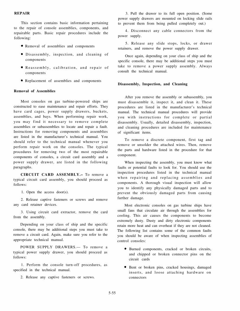
REPAIR
This section contains basic information pertainingto the repair of console assemblies, components, andrepairable parts. Basic repair procedures include thefollowing:
Removal of assemblies and components
Disassembly, inspect ion, and cleaning ofcomponents
R e a s s e m b l y , c a l i b r a t i o n , a n d r e p a i r o fcomponents
Replacement of assemblies and components
Removal of Assemblies
Most consoles on gas turbine-powered ships areconstructed to ease maintenance and repair efforts. Theyhave card cages, power supply drawers, buckets,assemblies, and bays. When performing repair work,you may f ind i t necessary to remove completeassemblies or subassemblies to locate and repair a fault.Instructions for removing components and assembliesare listed in the manufacturer’s technical manual. Youshould refer to the technical manual whenever youperform repair work on the consoles. The typicalprocedures for removing two of the most repairablecomponents of consoles, a circuit card assembly and apower supply drawer, are listed in the followingparagraphs.
CIRCUIT CARD ASSEMBLY.– To remove atypical circuit card assembly, you should proceed asfollows:
1. Open the access door(s).
2. Release captive fasteners or screws and removeany card retainer devices.
3. Using circuit card extractor, remove the cardfrom the assembly.
Depending on your class of ship and the specificconsole, there may be additional steps you must take toremove a circuit card. Again, make sure you refer to theappropriate technical manual.
POWER SUPPLY DRAWERS.— To remove atypical power supply drawer, you should proceed asfollows:
1. Perform the console turn-off procedures, asspecified in the technical manual.
2. Release any captive fasteners or screws.
3. Pull the drawer to its full open position. (Somepower supply drawers are mounted on locking slide railsto prevent them from being pulled completely out.)
4. Disconnect any cable connectors from thepower supply.
5. Release any slide stops, locks, or drawerretainers, and remove the power supply drawer.
Once again, depending on your class of ship and thespecific console, there may be additional steps you musttake to remove a power supply assembly. Alwaysconsult the technical manual.
Disassembly, Inspection, and Cleaning
After you remove the assembly or subassembly, youmust disassemble it, inspect it, and clean it. Theseprocedures are listed in the manufacturer’s technicalmanual. The technical manual procedures will provideyou with instruct ions for complete or par t ia ldisassembly. Usually, detailed disassembly, inspection,and cleaning procedures are included for maintenanceof significant items.
To remove a discrete component, first tag andremove or unsolder the attached wires. Then, removethe parts and hardware listed in the procedure for thatcomponent.
When inspecting the assembly, you must know whatfaults or potential faults to look for. You should use theinspection procedures listed in the technical manualwhen r epa i r i ng and r ep l ac ing a s sembl i e s andcomponents. A thorough visual inspection will allowyou to identify any physically damaged parts and toprevent the obviously damaged parts from causingfurther damage.
Most electronic consoles on gas turbine ships havesmall fans that circulate air through the assemblies forcooling. This air causes the components to becomeextremely dusty. Dusty and dirty electronic componentsretain more heat and can overheat if they are not cleaned.The following list contains some of the common faultsyou should be aware of when inspecting assemblies ofcontrol consoles:
Burned components, cracked or broken circuits,and chipped or broken connector pins on thecircuit cards
Bent or broken pins, cracked housings, damagedinserts , and loose at taching hardware onconnectors
5-55

Loose hardware, burned components, brokenconnect ions, and bent or broken pins onassemblies and subassemblies
You can clean the assemblies and subassemblies bywiping them with a dry cloth or brush. Use a watersoluble detergent to clean the air falters on controlconsoles. For general cleaning of the consoles, use ageneral cleaning solvent. To remove corrosion andoxidation from the aluminum surfaces of the consoles,use trichlorotriflouroethane. Remember to observe allsafety precautions when using cleaning solvents.
WARNING
Dangerous voltages exist in control consoles.Observe all safety precautions before performing any ofthe scheduled preventive maintenance.
Reassembly, Calibration, and Repair
When you replace a part, remember that the newpart must be electrically and physically identical to thedefective part. Identification of repair parts is given inthe parts listing of the technical manual.
Unless otherwise specified in the detail repairprocedures, use the following general rules whenrepairing the control consoles:
1. Remove and disassemble parts only to the extentnecessary to inspect, clean, or replace a defective part.
2. When removing attaching hardware, note thenumber and arrangement of hardware at each attachingpoint. Be sure to replace hardware properly whenreassembling the item removed.
3. Inspect all removed parts as specified in thetechnical manual. Install only parts that are serviceable.
4. Check to be sure that mating parts are properlyengaged and aligned before tightening the mountinghardware.
Repair of circuit cards will, in most instances,consist of removal and replacement of detail parts. Insome instances, however, the PCBs may be defective.You can make practical repairs of defective (open)printed conductors by installing jumper wires across theopen circuit. Upon completion of any circuit card repairoperation, calibrate and retest the circuit card. Aftercalibration and retesting, apply a polyurethane coatingto the reworked areas.
5-56
WARNING
Polyurethane materials are flammable and toxic. Do
not smoke or permit sparks or open flames in the work
area. The work area must be well vented. Wear eye
protectors, protective clothing, and polyethylene or
rubber gloves while working with the materials. Wash
hands and exposed skin areas thoroughly with soap and
hot water after handling.
Exe rc i s e ca r e and obse rve t he fo l l owing
precautionary measures during the handling and repair
of circuit cards. These measures will help you to prevent
further damage to the circuit cards and the replacement
parts.
1. Ensure all leads of removed parts are tagged.
2. Make sure all hardware removed is replaced in
the proper order.
3. Observe the polarity of the capacitors and
diodes.
4. Observe the placement and height of the
components.
5. Make sure the soldering iron you use for
integrated circuits is 18 watts maximum (tip temperature
between 450° and 550°F) and for other parts is 25 watts
maximum (tip temperature between 750° and 850°F).
6. Ensure that the leads of the replaced parts are
trimmed flush on the back of the circuit card.
7. Avoid accidental touching of the soldering iron
or other heated instruments to the wire insulation.
CAUTION
Do not touch integrated circuits with your bare
hands because of possible damage by static electricity.
The hand tools you use must be properly grounded.
Replacement of Assemblies
After performing repair work, you must replace the
assemblies or subassemblies. Instructions for replacing
assemblies or subassemblies are l is ted in the
manufacturer’s technical manual. In most cases,
replacement is the reverse of removal. Whenever special
instructions are necessary, they are given in the technical
manual. After replacing the assemblies, thoroughly
check out the repair and replacement.

SUMMARY
In this chapter, we have discussed your primary role
as a GSE in the maintenance of the electrical and
electronic systems associated with your ship’s mainp r o p u l s i o n p l a n t . W e h a v e d i s c u s s e d t h e
troubleshooting, maintenance, and repair of electronic,electromechanical, and electrohydraulic control circuitsand systems, motors and generators, controllers, jacks,plugs, multiconductor cables, and auxiliary systems. Wehave also discussed wire-wrapping techniques, pumplogic calibration procedures, casualty inspection andreporting procedures, and important safety techniques
and precautions you must observe whenever you areworking with energized electrical equipment andsystems.
As a GSE, you will be the backbone of electrical andelectronic maintenance in your ship’s engineeringdepartment. The information presented in this chaptercovers some of the most important areas of yourmaintenance and repair responsibilities. If you have anyquestions or you are uncertain about any of the sectionsin this chapter, we recommend you review thisimportant information before you begin the next
chapter.
5-57


CHAPTER 6
PRESSURE, TEMPERATURE, AND LEVEL CONTROLDEVICES
The consoles on board gas turbine-powered shipsmonitor and control various systems and equipment.These sy s t ems a r e mon i to r ed w i th p r e s su re ,temperature, and level gauges and meters. Controldevices are used to accomplish the monitoringfunctions. Control devices also generate the alarms thatare displayed on the consoles. A control device, in itssimplest form, is an electrical switching device thatapplies voltage to or removes voltage from a single load.In more complex systems, the initial device may set intoaction other control devices that govern pressures,temperatures, and liquid levels.
In this chapter we will describe the different controldevices that you, the GS, must troubleshoot and repair.These include pressure, temperature, and level controldevices. Upon completion of this chapter, you should beable to describe the types of control devices used on gasturbine-powered ships and their basic maintenanceprocedures.
PRESSURE CONTROL DEVICES
Pres su re i s one o f t he ba s i c eng inee r ingmeasurements that must be monitored aboard ship.Pressure control devices control the operation ofequipment. They stop and start motors, cycle ventilationdampers, and generate low- and high-pressure alarms tothe propulsion control systems. Pressure control devicesinclude pressure switches and pressure transducers.Pressure readings provided by these devices will allowyou to determine the operating condition of yourequipment.
PRESSURE SWITCHES
A pressure switch opens or closes a set of contactsat a preset pressure. Pressure switches can provide alarmindication or start an action, such as stopping an aircompressor at a preset pressure. A typical pressureswitch is shown in figure 6-1.
The operation of the pressure switch is simple.When the pressure reaches the preset value, thepressure-sensing mechanism operates. The actuation ofthe sensing mechanism causes a light to illuminate, an
Figure 6-1.—Typical pressure switch.
alarm to sound, or a piece of equipment to stop or start.The switch is normally enclosed in a metal case with aremovable cover. The metal case provides a pressureport and an electrical connection point. A pressureswitch converts pressure energy into electrical energy.Pressure switches are used on pneumatic and hydraulicsystems. The shapes, configurations, and sizes ofpressure switches may differ but the functions basicallythe same. The type of switch used depends upon itsapplication.
Construction
P r e s s u r e - o p e r a t e d s w i t c h e s a r e n o r m a l l ysingle-pole, single-throw, quick-acting switches. Anindividual pressure switch contains either a bellows ora diaphragm that works against an adjustable spring.The spring causes the electrical contacts to open or closeautomatically when the operating pressure rises or falls
6-1

from a specified value. A permanent magnet in theswitch provides a positive snap when the contacts areopened or closed. This snap action prevents excessivearcing at the contacts. The pressure at which the switchoperates is adjustable within ranges, such as 0-15,15-50, and 50-100. This adjustment is made by using therange adjustment screw.
Maintenance
Normal maintenance performed on pressureswitches is accomplished by using the PMS. Thismaintenance includes inspecting the switch for damage,corrosion, and proper operation.
differential. Bring the pressure to the value at which thecircuit is to be closed or opened. Turn the rangeadjustment screw slowly clockwise or counterclockwiseuntil the contacts operate. This adjustment will set theopen or closing pressure.
You have now brought the pressure to the pointwhere the circuit will be activated. Since the differentialadjustment screw is now set at minimum, the circuit willprobably operate at a lower pressure than desired.Therefore, turn the differential adjustment screwclockwise to widen the differential until the desiredac t iva t i ng p re s su re i s ob t a ined . Re fe r t o t hemanufac tu re r ’ s t e chn ica l manua l fo r de t a i l edinstructions on adjusting these switches.
When you inspect a pressure switch, look for anyphysical external damage, such as loose-fitting covers,damaged pressure and electrical connectors, and Troubleshooting
missing parts. Check inside the metal case for corrosionand the presence of water or oil. If water or oil is present,
After adjusting the operating range of pressurecheck the condition of the rubber gasket in the cover and
switches, check the operation through at least onereplace it if necessary.complete cycle. If you find a variation from the desired
During PMS, sometimes you must adjust the switch operating values, go through the entire adjustmentto bring the operating values back in tolerance. To set a procedure again. In an emergency, you can use thepressure switch, you first have to set a known pressure pressure of the system in which the switch is installedin the working range of the switch. Normally, you do instead of using the test setup. In this case, however, youthis by using a test setup, such as the one shown in figure should reset the switch as soon as possible using the test6-2. To set the operating range of the switch, turn the setup. After adjusting the switch, watch the operationd i f f e r en t i a l ad ju s tmen t s c r ew ( see f i g . 6 -1 ) through another complete cycle. If you cannot adjust thecounterclockwise against the stop for minimum switch, you must troubleshoot it.
Figure 6-2.—Setup for calibrating a pressure device.
6-2

When troubleshooting a pressure switch that cannotbe adjusted, you will normally find that it needs to bereplaced. In most cases, the switching mechanismmalfunctions and the switch cannot be repaired.Sometimes the bellows or diaphragm malfunctions. Inthis case, also, you will have to replace the switch. Whenyou must replace a pressure switch, refer to themanufacturer’s technical manual to make sure you havethe proper replacement.
When replacing a pressure switch, you mustremember that the switch is constantly energized evenif the equipment is not actually running. It is the closingand opening of the contacts that energizes the entireelectrical circuit. You must make sure that electricalpower to the pressure switch is secured before you beginto replace the switch. Follow the basic troubleshootingtechniques and al l applicable electr ical safetyprecautions whenever you repair or replace pressureswitches.
PRESSURE TRANSDUCERS
A transducer is a device that receives energy fromone system and retransmits it to another system. Thisretransmitted energy is often in a different form than itwas received. A pressure transducer receives energy inthe form of pressure and retransmits energy in the formof electrical current. A pressure transducer allowspressure monitoring at remote locations on gasturbine-powered ships. Pressure transducers provide thecapability of sensing variable pressures and transmittingthem in proportional electrical signals. Pressuretransducers are widely used in ship propulsion andauxiliary machinery spaces. They are often used to
Figure 6-3.—Pressure transducer assembly.
monitor alarms. A typical pressure transducer is shownin figure 6-3.
Like the pressure switch, the operation of thepressure transducer is also simple. Pressure transducerssense absolute, gauge, or differential pressure. Thetransducer receives pressure through pressure ports. Itsends an electrical signal, proportional to the pressureinput, through the electrical connector. Pressuretransducers are available in pressure ranges from 0 to 6inches water differential to 0 to 10,000 pounds persquare inch gauge (psig). Regardless of the pressurerange of a specific transducer, the electrical output isalways the same. The electrical signal is conditioned bysignal conditioners before being displayed on an analogmeter or digital display readout. The sensitive parts ofthe transducer are enclosed in a metal box with aremovable cover. The metal box provides pressure portsand an electrical connection point. The range of thetransducer used depends upon its application.
Construction
Pressure transducers are square metal boxes thatcontain one or two pressure ports, an electricalconnector, and a circuit card. (See fig. 6-4.) A test jackand two variable resistors are located on the circuit card.One resistor is the span adjustment resistor and the otheris the zero adjustment resistor. The transducer containsno moving parts; therefore, it is very reliable. Thepressure applied to the transducer is converted to anelectrical signal by the components on the circuit card
Maintenance
Maintenance performed on pressure transducers isaccomplished also by PMS. This maintenance includesinspecting the transducer for damage, corrosion, andproper operation.
Figure 6-4.—Transducer construction.
6-3

Figure 6-5.—Calibration setup for absolute pressure transducers.
6-4

When inspecting a pressure transducer, look for any While performing PMS, you may find it necessaryphysical external damage, such as loose-fitting covers, to calibrate a transducer that is out of tolerance.
damaged pressure and electrical connectors, and Calibrate pressure transducers on a bench before
missing parts. Check inside the metal case for corrosion installing them. This action will prevent damage to thetransducer and the equipment served.and the presence of water or oil. If water or oil is present,
check the condition of the rubber gasket on the cover The equipment needed for the setup to calibrate aand replace it if necessary. transducer is shown in figures 6-5 and 6-6. If your ship
Figure 6-6.—Calibration setup for gauge pressure and differential pressure transducers.
6-5

does not have the equipment or is not qualified tocal ibrate t ransducers , send the t ransducer to acalibration facility. Some ships have their owncalibration laboratories. If you have a problem with apressure transducer or have to replace one, you cancompare it with a known standard by using thecalibration setup. The following paragraph describes thesteps necessary to calibrate pressure transducerscommonly found on gas turbine-powered ships.
Make sure you fol low al l applicable safetyprecautions while calibrating pressure transducers.There are three values to check when you calibratetransducers: low, high, and middle. To calibrate apressure transducer, make sure the equipment served istagged out of service. Close the instrumentation valvein the pressure line to the transducer, remove the cap,and connect the hose to the instrumentation valve. (Theinstrumentation valve is closed by turning it fullyclockwise.) Remove the cover of the transducer andconnect the multimeter to the transducer test jack. The
multimeter should read 4 milliamps (mA) ±0.3. Ifnecessary, adjust the ZERO ADJUST resistor to get theproper reading. This is the low reading of the transducer.Set the multimeter to the proper scale and apply pressureto the transducer that equals the high value. If necessary,adjust the SPAN ADJUST resistor as required to get thecorrect current output value. Recheck your first and lastvalues whenever you adjust either the ZERO or SPAN
resistors. Next, check the middle value of the transducerby applying pressure to the transducer that equals themiddle value. Then check the transducer current output.Always refer to the manufacturer’s technical manual toget the correct values for the low, middle, and highset t ings of the t ransducer. When cal ibrat ion iscompleted, disconnect the calibration setup, replace thetransducer cover, and return the equipment to service.For additional information on calibration of transducers,refer to Propulsion Gas Turbine Module LM2500,Volume 2, Part 3, NAVSEA S9234-AD-MMO-050.
Troubleshooting
If you suspect a transducer is faulty, start yourtroubleshooting procedures by making sure the sameproblem exists on another console or panel. This stepwill help you make certain that you are not just dealingwith a faulty meter or indicator. After you verify that thetransducer is in fact faulty, you must isolate the cause ofthe fault.
TO troubleshoot a transducer, first disconnect thepressure transducer electrical connector and check for
correct input voltage ±1 between pins A (+) and B (-).Next, check the electrical connections and cables forshorts, opens, or grounds. Check the pressure transduceraccording to the maintenance requirement card (MRC).Replace the transducer if it cannot be calibrated. If all
Figure 6-7.—Pressure transducer.
6-6

these checks prove satisfactory, check your ship’s
instrumentation or uplink signals. For more detailed
troubleshooting procedures, refer to the manufacturer’s
technical manual.
When you must replace a transducer, read all
applicable instructions, class advisories, and bulletins
before removing the unit. All pressure transducers are
removed and installed in the same manner. Differential
pressure transducers, however, have two pressure lines.
(See the detail block in fig. 6-6.) Refer to figure 6-7 as
you read the description of the transducer removal
procedures. The numbers in parentheses refer to the
associated numbered parts in the figure.
To remove a t ransducer , f i rs t shut off the
instrumentation valves in the pressure lines to the
transducer. Secure and tag out the electrical power to the
transducer and remove the electrical lead (4) from the
unit. Next, remove the nut, washer, and bonding strap
(6) from the transducer stud (5). Disconnect the pressure
lines (1) from the transducer. Next, remove the bolts and
washers that secure the transducer to the mounting plate.
Remove the transducer. Finally, remove the pressure
line unions (2). Remove and discard the O-rings (3)
from the unions.
The following paragraph describes the procedures
you should use to properly replace a pressure transducer.
Again, follow along in figure 6-7 as you study this
procedure.
First, install new O-rings (3) on the unions (2). Next,
install the unions into the transducer and torque the
unions to 135 to 150 inch pounds (in. lb). Place the
transducer on the mounting plate so it is flat when the
locator pin is inserted into the transducer flange. Next,
install the bolts and washers to secure the transducer to
the mounting plate. Torque these bolts to 40 to 60 in. lb.
Connect the pressure lines (1) to the transducer and
torque the fittings to 135 to 150 in. lb. Next, attach the
bonding strap (6) to the stud (5) on the transducer with
the washer and nut. Torque this nut to 70 to 110 in. lb.
Make sure the seal is in the electrical lead (4) connector
and attach the lead to the transducer. Finally, remove the
tag and restore electrical power to the transducer.
Calibrate the pressure transducer according to the
applicable MRC. Follow the basic troubleshooting
procedures and al l applicable electr ical safety
precautions whenever you calibrate, remove, andreplace pressure transducers.
TEMPERATURE CONTROL DEVICES
Temperature, like pressure, is one of the basicengineering measurements that must be monitored aboardship. Like pressure readings, temperature readings alsoprovide you with an indication of the operating conditionof the equipment. Temperature control devices operatefrom changes in the temperature that take place in anenclosure or in the air surrounding the temperature-sensingelement. Temperature control devices are used withhigh-temperature alarm systems, generator airtemperature control circuits, and fire detection alarmsystems. They are also used to stop and start ventilationmotors and to control the heating of fuel and lube oil.Common temperature control devices include temperatureswitches and thermocouples.
TEMPERATURE SWITCHES
A temperature switch opens or closes a set of contactsat a preset temperature Temperature switches providealarm indications or stop a piece of equipment if a hightemperature condition develops. A temperature switchwith two types of sensing elements is shown in figure 6-8.The main function of a temperature switch is to convertthermal energy into electrical energy. Although the shapes,configuration, and sizes of temperature switches maydiffer, their primary function is the same.
Construction
Temperature-operated switches are usual lysingle-pole, single-throw, quick-acting, normally open
Figure 6-8.—Temperature switch with two types of sensingelements. A. Bulb unit. B. Helix unit.
6-7

switches. However, temperature switches can also benormally closed switches. A basic temperature switchcontains a bellows or a diaphragm that works against anadjustable spring. The spring causes the electricalcontacts to open or close automatically when theoperating temperature exceeds a specified value. Thebellows or diaphragm motion is produced by a sealed-ingas that expands with rising temperature. The sensitiveelement containing this gas may be built into the switchor located in a remote space and connected to the switchby a capillary tube. A permanent magnet in the switchprovides a positive snap when the contacts are openedor closed. This snap action prevents excessive arcing atthe contacts. The design of the switch allows movementof the contacts to determine whether the switch opensor closes on a temperature rise. The switch is normallyenclosed in a metal case with a removable cover. Themetal case provides a temperature-sensing port and anelectrical connection point. The temperature at whichthe switch operates is adjustable.
Operation
The operation of the temperature switch is basicallythe same as that of the pressure switch. In fact,temperature switches are actually operated by changesin pressure. The temperature element is arranged so achange in temperature will cause a change in the internalpressure of the sealed-gas or air-filled bulb or helix thatis connected to the actuating device by a capillary tube.A temperature change will cause a change in the volumeof the sealed-in gas. This, in turn, will cause movementof the bellows or diaphragm. The movement is sent by
a plunger to the switch arm. The moving contacts are
located on this arm. A fixed contact maybe arranged so
the switch will open or close on a temperature rise.
Maintenance
Routine maintenance performed on temperature
switches should be accomplished according to PMS.
The routine maintenance procedures performed on
temperature switches are the same as those discussed for
pressure switches. Routine maintenance includes
inspecting the switch for damage, corrosion, and proper
operation. The procedures for adjusting the switch were
discussed earlier in this chapter. The only difference is
the test setup you will use to calibrate the switch.
The Navy uses several different pieces of equipment
for calibrating heat-sensing devices. There are also
several methods for calibrating temperature devices.
The King Nutronics, models 3604 (fig. 6-9, view A) and
3605 (fig. 6-9, view B), are portable temperature
comparators. These two units provide the latest in
solid-state, digital technology for the Navy. The model
3604 is used to calibrate temperature control devices
within a range of 100° to 1199°F. The model 3605 is
used to calibrate temperature control devices within a
range of -40° to +250°F. Usually, temperature switches
on gas turbine-powered ships are calibrated at regular
intervals by a calibration team. If a switch malfunctions,
it is removed and sent to a calibration lab for testing.
Figure 6-9.—King Nutronics. A. Model 3604. B. Model 3605.
6-8

Troubleshooting
After calibrating the temperature switch, check itsoperation through at least one complete cycle. If youfind a variation from the desired operating values, havethe switch recalibrated. In an emergency, you can adjustthe temperature switch while it is in the system insteadof sending it for calibration. You should, however, sendthe switch to the calibration lab as soon as possible fora thorough adjustment. If the switch cannot be adjusted,you must troubleshoot the switch or replace it.
Temperature switches, like pressure switches,normally require replacement if they cannot be adjusted.When you adjust temperature control devices, allowseveral minutes for the thermal unit to reach thetemperatures of the surrounding air, gas, or liquid beforesetting the operating range. If replacement of at empera tu re swi t ch i s neces sa ry , r e f e r t o t hemanufacturer’s technical manual to be certain you havethe proper replacement.
As w i th p r e s su re sw i t ches , r emember t hetemperature switch is constantly energized even if thesystem is secured. The closing and opening of thecontacts energize the entire electrical circuit. You mustmake sure electrical power to the pressure switch issecured before you replace the switch. Follow the basictroubleshooting techniques and all applicable electricalsafety precautions whenever you repair or replacetemperature switches.
THERMOCOUPLES
The temperature of a body may be measuredwithout any physical contact with it by use of aninstrument that senses radiation. Such an instrument isknown as a radiation pyrometer. This device isc o m m o n l y c a l l e d a t h e r m o c o u p l e o n g a sturbine-powered ships. Thermocouples used aboardship measure temperatures in the gas turbine engine.
Construction
Thermocouples are composed of two dissimilarmetals joined at one end to produce a change in voltagethat is proportional to a change in the temperature at thejoined end. A voltmeter (calibrated in degrees) showsthe temperature at the thermocouple.
Types of metals or alloys used in combination int h e r m o c o u p l e s a r e ( 1 ) c h r o m e l - a l u m e l , ( 2 )copper-constantan, (3) i ron-constantan, and (4)platinum-platinum rhodium. Other combinations alsomay be used for special purposes. The thermocouples
found on gas turbine-powered ships are usually thechromel-alumel type.
Due to the high cost of thermocouple wire, a lessexpensive lead wire is often used to connect thethermocouple wires to the temperature-indicatinginstrument. However, to reduce errors, make sure youge t l ead wi re s w i th t he s ame the rmoe lec t r i ccha rac t e r i s t i c s a s t he t he rmocoup le w i r e . Fo rchromel-alumel thermocouples, copper and constantanlead wires are often used. These lead wires are morerugged than thermocouple wires and may be solid orstranded.
Maintenance
Routine maintenance performed on thermocouplesshould be accomplished by PMS. Thermocouplesshould be checked regularly. If possible, they should bechecked when they are in place. If it is necessary for youto remove a thermocouple, be sure to return it to thesame insertion depth or deeper. This will prevent errorsresulting from the irregular heating of different portionsof the wire.
One prime requirement for a thermocouple to meettolerance is that it must be unvarying. Remember, whenthermocouples are handled they can be bent orcontaminated. This is why you must use extreme care.Both bending and contamination will cause thethermocouple to become erratic, thereby affecting itsoperation and increasing the likelihood of error.
Troubleshooting
Normally, malfunctioning thermocouples arenoticed during equipment operation. A console operatormust know the correct operational parameters of theequipment he or she is monitoring. While takingreadings on a GTE, if the turbine inlet temperature isincorrect or not consistent with previous readings, theoperator should know something is wrong. The problemc o u l d b e a m a l f u n c t i o n i n g t h e r m o c o u p l e o rthermocouple circuit. As a GSE, you will be called toinvestigate the problem.
When you are troubleshooting a thermocouple,several common faults can occur. Thermocouples, likeother electrical equipment, can be grounded, open, orshorted. The thermocouples on most GTEs areconnected in parallel. In troubleshooting this type ofsetup, you will have to isolate the thermocouplessystematically to locate which particular thermocoupleo r t he rmocoup le s e t i s f au l t y . Some gene ra l
6-9

troubleshooting procedures are discussed in thefollowing paragraph.
Since thermocouples monitor temperature, youm u s t a l l o w t h e m t o c o o l b e f o r e y o u b e g i ntroubleshooting. Thermocouples on GTEs can be cooledb y m o t o r i n g t h e e n g i n e . Y o u c a n c h e c k t h ethermocouple and its leads by using a multimeter to takeresistance readings. Take resistance readings betweeneach pin and each pinto ground. Check the technicalmanual to determine if the readings are within theminimum acceptable limits. If the thermocoupleresistance system measurements are within limits,troubleshoot the ship’s instrumentation. As mentionedearlier in this chapter, always refer to the manufacturer’stechnical manual when you test, troubleshoot, and repairany electrical equipment.
LEVEL CONTROL DEVICES
In the engineering plant on a gas turbine-poweredship, operating personnel must know the levels of thevarious liquids in different locations in the ship. Thelevel in the ship’s freshwater tanks is an example of aliquid level that must always be known. There are otherliquid levels that are also important. These include thelevels in the fuel oil service tanks, fuel oil stowage tanks,lubricating oil sumps, and drain tanks.
A wide variety of devices, some of them simple andsome complex, are available for measuring andcontrolling liquid levels. Without level control devices,engineering and operating personnel could not plan fortheir supply needs. GSEs are responsible for the repair,maintenance, and installation of these devices. Levelcontrol devices used aboard gas turbine-powered shipsinclude liquid-level float switches and magnetic floatdevices.
LIQUID-LEVEL FLOAT SWITCHES
A relatively new development in indicating alarmand control functions is the liquid-level float switch. Aliquid-level float switch is shown in figure 6-10. Thistype of switch is usually found in tank- and bilge-levelalarm circuits.
T h e l i q u i d - l e v e l f l o a t s w i t c h h a s adoughnut-shaped, floatable magnetic core operatingover an encapsulated reed switch. The entire assemblyis mounted at a predetermined level. The switch can bemade normally open or closed by reversal of the core.Level conditions are shown as normal, above normal, orbelow normal. The switch can also be used to start andstop pumps, such as in a drain tank system. When the
6-10
Figure 6-10.—Liquid-level float switch.
liquid level reaches a preset point, the float switchcompletes the circuit to the pump, signaling the pumpto start to remove the liquid from the tank. When thelevel drops to the preset point, the pump secures.
MAGNETIC FLOAT DEVICES
Each tank level indicator (TLI) system is made upof equipment and accessories that are necessary for thespecific installation. The TLI system components can bedivided into four general groups: (1) the liquid-leveldetection devices (transmitter), (2) the receiver devices(receiver panel or module), (3) the remote alarm orliquid-level indicating devices (alarm and gauges), and(4) the accessories (tubing and so forth). Thesecomponents are shown in figure 6-11.
The purpose of the liquid-level detection devicesinstalled in tanks is to convert the liquid level into anelectrical signal. The two types of detection devicesavailable are the transmitters and the level links.Transmitters provide a continuous level measurement,while level links provide a point or incrementalmeasurement.
Study the transmitter shown in figure 6-12. Thetransmitter consists of a network of voltage dividerresistors and magnetic reed switches contained in silicon

Figure 6-11.—Magnetic float systems.
Figure 6-12.—Magnetic float liquid-level detector.
6-11

Figure 6-13.—Link transmitter float assembly.
rubber and potted in a mylar tube. The tube issurrounded by a neoprene tube and is mounted inside astainless-steel tube. Electrical leads connect the resistorsand magnetic reed switches to electrical connectorslocated either at the top, bottom, or both ends of thetransmitter.
Now study the link transmitter float assemblyshown in figure 6-13. The link system (views A and B)can be used alone or in combination with transmitterassemblies. Each level link system includes severalcable-connected station assemblies. Individual stationassemblies include magnet-equipped floats that ride upand down on stems. Each stem houses a resistor,magnetic reed switches, and a semiconductor diode. Amounting bracket is provided on the stem for individualmounting of each station assembly of the system.
Receiver devices are used to convert the electricalsignals generated by the level detection devices intodeflections of a pointer on a meter. The meter is usuallymarked in gallons. Primary receiver modules performlevel indication, alarm generation, and alarm indicationfunctions for one tank. A receiver panel provides thesame function for several tanks.
The magnetic float system is operated by thechanging liquid level in the tank. As the liquid levelchanges, the float moves up or down the transmitter.Figure 6-14 shows how bar magnets in the float operatetap switches in a two-at-a-time, three-at-a-time,two-at-a-time closing sequence as the float moves up thetransmitter. When two adjacent tap switches are closed,the effective electrical tap point on the voltage dividernetwork is halfway between the two switches. As the
6-12

Figure 6-14.—Transmitter tap switch operational sequence.
float closes the next tap switch (the first two are stillclosed), the effective tap point is halfway between thefirst and third tap switches; that is, it is at the middleswitch. This middle point is 1/2 inch from the effectivetap point established when only two tap switches were
Figure 6-15.—Overlapped transmitter transfer switchoperation.
closed. As a result, voltage drops are read in 1/2-inch
increments of float travel.
When two or more transmitters are installed in a
tank, each transmitter except the bottom transmitter has
a transfer switch. These switches are of the type shown
in figure 6-15. The transfer switch is a magnetically
operated reed switch. It is connected between the
common conductor (to the tap switch resistances) in one
transmitter and the common conductor in the next lower
transmitter. The transfer switch is held closed when the
float on its transmitter is at the bottom limit. As the float
level rises with the fluid level, the transfer switch opens
and disconnects the tap switches in the lower transmitter.
The transfer switch action is required to open the
common conductor circuit to the lower transmitter tap
switches. The uppermost tap switch of the lower
transmitter tap switches is held closed now, since the
lower transmitter float is at its top limit of travel. The
resulting voltage change produced by the changing tank
level is processed by the receiver module, and the liquid
level is indicated on the meter.
The liquid-level switches on board your class of
ship may differ somewhat. However, the principle of
operation will be similar to the one just discussed. For
specific operational characteristics, refer to the
manufacturer’s technical manual for the system on your
ship.
6-13

MAINTENANCE
Routine maintenance performed on most liquidcontrol devices is accomplished by PMS. Routinemaintenance includes inspecting the devices for damageand proper operation. To check for proper operation, youmust lift some liquid control devices manually. You willcheck others, such as tank level sensors, throughcalibration circuits. Some difficulties that you may facein working with liquid control devices are inaccuratereadings, uni ts that are out of cal ibrat ion, andmalfunctioning floats. For specific maintenance andcalibration procedures, refer to the applicable systemtechnical manual.
The moving parts of liquid control devices shouldbe inspected for smooth operation. They should also belubricated at definite intervals. When spare parts areavailable, repairs and replacements should be made onlyby experienced GSEs. In several cases, it is best toreplace the entire liquid control device and return thefaulty one to the manufacturer (if required).
TROUBLESHOOTING
Most problems with liquid control devices arediscovered during PMS. You may find that duringcalibration a meter might not indicate the level it issupposed to. You must find the problem by startingproper troubleshooting procedures. Troubleshootingprocedures include reading voltages, resistances, andcurrents as well as performing calibration.
If you find a faulty liquid control device, you mustreplace it as soon as possible. Sometimes this is a simpleprocess, while other times it will take the participationof many personnel. If the control device is a bilge levelsensor, the replacement procedure is simple. Just tag outthe circuit and replace it. However, if the control deviceis a fuel tank level sensor, the replacement proceduresget a bit more complex. The fuel has to be pumped out
of the tank, the tank certified gas free by a gas freeengineer, and specific safety precautions observed.When replacing a liquid control device, take care intagging the leads to assure proper replacement.
After you enter the tank, you may find the problemis a stuck float. To correct this problem, carefully cleanand scrape the tube so it offers a smooth surface for thefloat. If you have to disassemble a liquid control device,be sure to clean all metal parts with a solvent.
Most liquid control devices are constantly energizedeven when the tank is empty or the system is secured.You must make sure that electrical power to the controldevice is secured before replacing it. Follow the basictroubleshooting techniques and all applicable electricalsafety precautions when troubleshooting, repairing, orreplacing liquid control devices.
SUMMARY
In this chapter, we have discussed your responsi-bility for the maintenance of pressure, temperature, andlevel control devices . We have discussed thetroubleshooting, maintenance, and repair of pressureswitches, pressure transducers, and temperatureswitches. We also described the different types of levelcontrol devices used aboard gas turbine-powered shipsand the maintenance procedures you must use for them.We also talked about the safety precautions associatedwith the troubleshooting and maintenance of pressure,temperature, and level control devices.
These simple devices are vital to the operation ofthe engineering plant on a gas turbine-powered ship. Asa GSE, the attention you give these devices will preventseveral equipment malfunctions associated with yourrating. The information presented in this chapter coversthe basic operation and maintenance of control devices.I f you have any quest ions about the pressure ,temperature, and level control devices just discussed, werecommend you refer to the proper technical manual.
6 - 1 4

CHAPTER 7
LCAC AND PHM PROPULSION SYSTEMS
The GSEs assigned to landing craft, air cushion(LCAC) ves se l s and pa t ro l comba tan t mi s s i l e(hydrofoil) (PHM) class ships are responsible for theupkeep and maintenance of the propulsion electroniccontrol systems. If you are assigned to an LCAC or aPHM, the watches you will stand will be different fromthose on the DD-963, DDG-993, DDG-51, CG-47, andFFG-7 class ships. In this chapter you will read aboutsome o f t he se d i f f e r ences and t he a s soc i a t edresponsibilities you may be expected to assume.
After reading this chapter, you should be familiarwith the operation of the engineering plant equipmenton the LCAC and PHM class ships. The informationpresented in this TRAMAN is designed only tofamiliarize you with the equipment on these ships.Remember, you should always use the appropriateEOSS and PQS to qualify for a particular watch station.
After reading this chapter and completing theassociated self-study questions in the NRTC, you shouldhave acquired enough knowledge to begin qualifying atthe individual watch stations on board these ships. Eventhough you may never be assigned to an LCAC or PHM,the information in this chapter should familiarize youenough with the equipment to help you advance in theGSE rating. As you become more senior in the GSrating, you may find yourself assigned to an LCAC orPHM class ship, or to one of their maintenance depots.In either case, this indoctrination could help you beginyour qualifications.
LANDING CRAFT, AIR CUSHION
The LCAC is a high-speed, ship- to-shore,over-the-beach vehicle that will deliver a 60-ton payloadto the ground elements of a Marine amphibious force. Itprovides the Navy and Marine Corps with high-speeddelivery capabilities to support amphibious operations.
The LCAC is an air cushion vehicle that is poweredby four AVCO Aerospace TF40B marine gas turbinesthat provide a total of 15,820 horsepower (hp). Twoshrouded reversible pitch propellers ‘provide forwardand reverse motion. The air cushion on which the craftrides is created by four double-entry fans. These fans are63 inches in diameter, providing the desired amount ofairflow. The steering system consists of two rotatable
bow thrusters and two aerodynamic rudders. Figure 7-1is an illustration of an LCAC craft.
The LCAC eng inee r ing p l an t cons i s t s o fpropulsion, lift, and control systems. The plant isoperated by the craft engineer/assistant operator whilethe craft is underway. There are no traditional watchesas these limited endurance craft carry only enoughpersonnel to man the operating stations. The crewconsists of an operator, craft engineer/assistant operator,navigator, load master, and deck hand/engineer. Thissmall crew is completely responsible for underwayoperations, and embarkation and disembarkation oft roops and suppl ies . The only GS is the craf tengineer/assistant operator.
In the following paragraphs, we will describe thebasic physical and functional characteristics of theLCAC control systems. The LCAC control systemsinclude all the systems and controls the operator needsto maneuver the craft. Maneuvering an LCAC basicallyconsists of controlling the craft’s direction, speed, andcushion.
The LCAC control systems are divided into thefollowing subsystems:
1
2
3
4
5
6
7
8
Steering control system
Propeller pitch control system
Lift fan control system
Lycoming TF40B engine control system
Command and control keyboard
Rate of turn system
Outside air temperature system
Speed/sideslip indicator
These subsystems are controlled by the operator inthe LCAC operator station command module or theoperator in the engineer control station. Figure 7-2shows the physical arrangement of a typical LCACoperator station command module. Now, let’s take abrief look at each of these subsystems and how they areused. After we look at the control systems, we willdiscuss the electrical system that provides the electricalpower for these units.
7-1
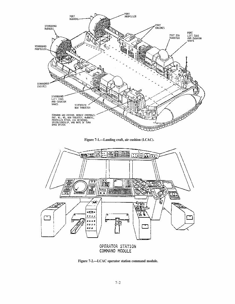
Figure 7-1.—Landing craft, air cushion (LCAC).
Figure 7-2.—LCAC operator station command module.
7-2

STEERING CONTROL SYSTEM
Just as its name implies, the steering control system
allows the operator to steer the craft from the LCAC
control station module. The steering control system is
composed of both the rudder control system and the bow
thruster control system and the associated operational
controls, as shown in the shaded areas of figure 7-3. In
the following paragraphs, we will briefly describe the
major assemblies and components and their functionswithin the design and operation of the craft controlsystem.
Rudder Control System
The function of the rudder control system is toprovide the capability for turning power at the stern ofthe craft. Figure 7-4 shows the basic configuration ofthe rudder control system. (Study and compare figs. 7-1
Figure 7-3.—Steering control station.
Figure 7-4.—Physical arrangement of the rudder control system.
7-3

through 7-4.) Study figure 7-4 as you read about thecomponents and their functions.
There are two rudders mounted vertically across thetrailing edge of each propeller duct. The rudders are usedwith the bow thrusters to provide turning capability. Thefunction of the rudders is to deflect propeller slipstreamwhich, in turn, provides a turning force at the stern ofthe craft.
Operation of the rudder control system is based onhydraulic pressure. In fact, a hydraulic pressure systemsupplies power to both the rudder control system and thepropeller pitch control system. There is a separatehydraulic system for each side of the craft, consisting ofpumps, valves, actuators, and piping. The control stationoperator controls the rudders by moving the ruddercontrol pedals forward or aft, as required. Movement ofa rudder control pedal is converted into an electricalsignal. The electric signal, in turn, controls a hydraulicposition actuator that moves the rudder for that side ofthe craft to the selected position. Figure 7-3 shows thelocation of the rudder control pedals at the steeringcontrol station. Figure 7-5 shows a side view of therudder pedal assembly.
P E D A L C O N T R O L S . – The control stationoperator moves the rudders by operating the two pedalson the rudder control assembly. (See shaded areas offigs. 7-3 and 7-5.) The rudder pedals pivot on an axleto allow the operator to move the rudders in bothdirections. To move the rudders to full port or fullstarboard, the operator pushes the port or starboardpedal forward. This action causes a potentiometer to
send a negative (port) or positive (starboard) electricalsignal through the control system electronic package(CSEP) and to the rudder actuator, thereby causing therudder to move left or right as directed. The pedalcontrols are spring-loaded to allow them to return to theneutral position after the rudder has moved to thecommanded position.
C S E P A N D R U D D E R I N T E R F A C E A S -SEMBLY.— The function of the CSEP is to control andsend the command signals initiated by the operator inthe control station to the various components in the craftcontrol system. The LCAC has two identical CSEPs,labeled CSEP A and CSEP B. Each CSEP has a singlecircuit specifically for rudder control. A rudder controlsignal initiated by the control station operator will berouted through one of these channels to the ruddercontrol components. The operator can use either CSEPA or CSEP B to route a rudder control signal.
R U D D E R P O S I T I O N D R I V E A S -SEMBLY.— The rudder position drive assemblycontains a valve coil, hydraulic drive servo motor, andfeedback potentiometer. The CSEP sends an electricaldrive signal to the electric drive servo motor through thevalve coil to position the rudders. As the rudders arepositioned, a feedback signal goes to the CSEP. Whenthe feedback signal is equal and opposite to the drivesignal, the rudders are in the desired position.
RUDDER BLADES.– The craft’s two rudders aremounted vertically across the trailing edge of eachpropeller shroud. The rudder blades are broad, flat,aerodynamic, movable devices that measure 10.4 feet
Figure 7-5.—Rudder pedals.
7-4

long and 2.3 feet wide. The rudder blades allow the Bow Thruster Control Systemoperator to maneuver the craft by deflecting thepropeller slipstream at various angles. The purpose of the bow thruster control system is
RUDDER CHANNEL SELECTOR SWITCH.—to allow the operator to turn the bow of the craft and to
The rudder charnel selector switch is located on themove the craft in close places. This system is extremelyuseful when the operator must dock and undock the
command and control (C&C) keyboard at the engineerLCAC in the dry well of the support ship.
station. This switch, labeled RUDDER A/B, allows theoperator to choose between channels of the CSEP in The bow thruster control system and assembly
case of an emergency or system fault. consists of two bow thrusters (one port and one
R U D D E R C O N T R O L S Y S T E M I N D I C A -starboard), the steering yoke assembly, and the
TORS.– Indicators are provided on the alarm andassoc i a t ed e l ec t r i ca l and hydrau l i c ope ra t ingmechanism. The physical arrangement of these
monitor system (AMS) cathode ray tube (CRT) displaycomponents and assemblies is shown in figure 7-6. The
monitor. The display monitor is located at the engineerbow thrusters provide thrust for the craft. The controls
control station. The indicators include the following:and operating mechanisms allow the control station
Rudder control failure operator to control the rotation of the bow thrusters toachieve the desired directional thrust. Basically, the
Port and starboard hydraulic reservoir low control station operator uses the steering yoke in the
Port and starboard hydraulic pressure low steering control assembly to turn the craff right or left,respectively. Turning the yoke left causes the craft toturn left, while turning the yoke right causes the craft toturn right. The steering yoke contains potentiometers
Figure 7-6.—Physical arrangement of the LCAC bow thruster control system.
7-5

that detect yoke movement and send electrical signalst h rough t he CSEP to t he hyd rau l i c ope ra t i ngmechanism.
Like the rudder control system, the bow thrustercontrol system uses hydraulic power to turn the bowthrusters. A system of pumps, flow control valves, andpiping supplies hydraulic power to the bow thrusterwheel units and lift fan cushion vanes. When theoperator turns the yoke, electrical signals are generatedand routed through the CSEP to the bow thrusteractuators. The basic components of the bow thrustercontrol system are the steering yoke, forward/reverseswitch, bow thruster drive mechanism, turning vanes,channel selector switch, and indicators.
STEERING YOKE.— The relative location of thesteering yoke in the operator control station is shown infigure 7-3. The components and controls of the steeringyoke are shown in greater detail in figure 7-7. Theoperator at the steering control station uses the steeringyoke to control the direction of the bow thrusters. Thesteering yoke will turn 45° in either direction.
FORWARD/REVERSE SWITCH.— This switchallows the operator to select the direction in which thebow thrusters apply thrust. The switch is located on thesteering yoke. (See fig. 7-7.) The switch allows anelectrical signal to pass through the CSEP to the bowthruster drive mechanism to position the bow thruster asordered.
BOW THRUSTER DRIVE MECHANISM.— Thebow thruster drive mechanism works to move the bow
Figure 7-7.—Steering yoke and controls.
thrusters to the position ordered by the operator. Whenthe yoke is turned, it positions a potentiometer and sendsan electrical signal to a mode and bias amplifier in theCSEP. The signal then goes to the bow thruster drivemechanism to position the bow thruster. The bowthruster turns, positioning a feedback potentiometer, andsends a feedback signal to the CSEP. When the feedbacksignal equals the command signal, the bow thruster is inthe desired position.
BOW THRUSTER TURNING VANES.— Thepurpose of the turning vanes is to direct airflow towardand out of the bow thrusters. Figure 7-8 shows theconfiguration of the bow thruster turning vanes. Noticehow the fixed vanes are attached into the air duct of thelift fan module and into the bow thruster volute. Thisdesign allows the airflow to reach the bow thrusters witha minimum of turbulence inside the volute and air duct.
BOW THRUSTER CHANNEL SELECTORSWITCH.— The bow thruster channel selector switch islocated on the C&C keyboard at the engineer station.This switch, labeled BOW THRUSTER A/B, allows theoperator to choose between channels of the CSEP incase of an emergency or system fault.
BOW THRUSTER INDICATORS.— The functionof the bow thruster control system indicators is to informthe operator of existing operating conditions and alarmconditions concerning the following areas:
Bow thruster control failure
Port and starboard hydraulic reservoir low
Port and starboard hydraulic pressure low
Now that you have read about the most importantcomponents of the steering control system, let’s take alook at an associated system that is supplied by the samehydraulic power source–the propeller pitch controlsystem.
PROPELLER PITCH CONTROL SYSTEM
The purpose of the propeller pitch control system isto allow the operator to control the speed and directionof the LCAC by changing propeller pitch. The LCACpropeller assembly is capable of both forward andreverse pitch. The greater the angle of pitch, the fasterthe craft will move.
The propeller pitch control system is composed ofthe yoke assembly, propeller pitch indicator, a controlunit, propeller pitch control levers, potentiometers, andamplifiers. The control station operator controls thepropeller pitch by using the two levers on the left-hand
7-6

Figure 7-8.—Bow thruster turning vanes.
console and the in/out movement of the yoke. Pushingthe yoke in or pulling it out will send electrical signalsto the electrohydraulic servo valve and actuator,allowing the operator to control the pitch of thepropellers. An indicator at the operator station providesan indication of propeller pitch. Figure 7-3 shows thephysical location of the propeller pitch controls in theoperator station. Let’s talk about some of these controlsand how they work.
Propeller Pitch Control Levers
The function of the propeller pitch control levers isto allow the operator to control the pitch of thepropellers. By controlling the pitch of the propellers, theoperator can control the speed and direction of the craft.Figure 7-9 shows a detailed view of the propeller pitchcontrol levers. Each control lever has a detent stop atzero degrees of propeller pitch with adjustablemechanical stops at both ends. The propellers areadjustable from +40° to -30°.
Figure 7-9.—Propeller pitch control levers.
7-7

Propeller Pitch Drive Assembly
The propeller pitch drive works to position the
propeller to the position ordered by the operator. Whenthe operator moves the control levers, an electricalsignal range is produced and sent to the CSEP where itis amplified. From the CSEP, the amplified signal is sentto the propeller pitch drive mechanism. The propellerpitch drive mechanism turns the propeller, causing afeedback potentiometer to send a signal to the CSEP.When the feedback signal equals the command signal,the propeller is in the ordered position. The propellerpitch drive mechanism can also be triggered by thevernier pitch control circuit we will describe in thefollowing paragraph.
Vernier Pitch Control Switch
The function of the vernier pitch control switch isto allow the operator to select the control source, orcombination of control sources, to control propellerpitch. When the vernier pitch control switch is in theOFF position, the operator can control propeller pitchonly by moving the control levers. When the vernierpitch control switch is ON, the operator can controlpropeller pitch by using both the control levers and thein-and-out movement of the yoke. The operator uses thecontrol levers to set the midrange for the yoke propellerpitch control range.
Propeller Pitch Selector Switch
The propeller pitch channel selector switch islocated on the C&C keyboard at the engineer station.This switch, labeled PROP A/B, allows the operator tochoose between channels of the CSEP in case of anemergency or system fault.
Propeller Pitch Control System Indicators
The function of the propeller pitch indicators is toinform the operator of existing conditions. The operatoruses this information to move the craft as effectively andsafely as possible. This subsystem informs the operatorof the following conditions:
Propeller control failure
Port and starboard hydraulic reservoir low
Port and starboard hydraulic pressure low
Propeller pitch
These indicators are provided at both the operatorcontrol station and the engineer control station.
You have just read about the steering control systemand the propeller pitch control system. Now, let’s take alook at another system that works with these twosystems to allow the operator to maneuver the craft.
LIFT FAN CONTROL SYSTEM
The lift fan control system allows the engineer tocontrol the airflow to the cushion of the craft. Anemergency dump switch is provided at the operatorcontrol station to allow the operator to stop the craft inan emergency by taking it off the air cushion.
The structure of the lift fans and associated vanecushion assembly is shown in figure 7-10. The maincomponents of this system are four double-entrycentrifugal fans. A rectangular box structure containingtwo lift fans is located on each side of the craft. The fans
Figure 7-10.—Lift fans and cushion vanes assembly.
7-8

are driven by the TF40B gas turbine engines throughright-angle gearboxes, as illustrated in figure 7-11. Thelift fan control system uses the output of the TF40Bengines, throughshafts, and reduction gears to turn thefans that provide air to the cushion and the bow thrusters.
Sixty percent of the air goes to the cushion and fortypercent goes to the bow thrusters. The air going to thecushion can be increased or decreased by opening orclosing the four sets of cushion vanes. Let’s take a lookat the components of this system and how they work
Lift Fans
As described earlier, there are two identical lift fan
has one discharge volute directed upward to the bowthruster assembly.
Solenoid-Operated Valves
Four 4-way, 3-position solenoid-operated valvesallow the engineer to control the cushion vanes.Momentary push-button switches located on the C&Ckeyboard allow the operator to control these valves. (Seefig. 7-12.) Each valve has an A and a B solenoid.Solenoid A energizes when the VANE CLOSE pushbutton is depressed. Solenoid B energizes when theVANE OPEN push button is depressed. Depressing thepush button allows hydraulic pressure to be applied tothe actuator, which causes the cushion vane to operate.
assemblies port and starboard. Each side has two These valves have manual overrides in case andouble-discharge centrifugal fans, four air inlets, four emergency occurs.discharge ducts, and eight flow control vanes. Each airinlet is protected by a foreign object damage (FOD) Cushion Vanesscreen. Each fan is installed on an individual shaft.These shafts are connected to each other and then to the The function of the cushion vanes is to allow theforward offset gearbox by flexible couplings. Each fan engineer to control the amount of airflow going to the
Figure 7-11.—TF40B propulsion and drive system arrangement.
7-9

cushion vanes and bow thrusters. Four switches on theC&C keyboard allow the engineer to control thesevanes. The 16 vanes in the system are adjustable throughany degree of rotation ordered by the operator.
OPERATING MECHANISM.— The purpose ofthe cushion vanes operating mechanism is to open andclose the cushion vanes. Each mechanism consists offour bellcrank assemblies, four torque tubes, and one
actuator. Hydraulic pressure supplied to the actuator,through the 4-way, 3-position, solenoid-operated valve,
causes the bellcranks to turn and operate the cushionvanes.
EMERGENCY CUSHION DUMP SWITCH.—The emergency cushion dump switch allows theoperator to dump the craft air cushion during anemergency stop. When the switch is depressed, all four4-way, 3-posi t ion, solenoid-operated valves are
energized to supply adequate hydraulic pressure to thehydraulic actuators. The actuator movement closes allfour cushion vanes and takes the craft off cushion.
SELECTOR SWITCHES.– Four momentary-contact push-button selector switches located on theC&C keyboard allow the cushion vanes to be openedand closed from the engineer station. These switches donot use power from the CSEP.
INDICATORS.— The following indicators areprovided to inform the operator of the status of thecushion vanes:
Port and starboard cushion vane position (bargraph)
Port and starboard cushion vane digital position
The operator uses this information to achieve themost effective movement of the craft.
Figure 7-12.—Command and control (C&C) keyboard.
7-10

LYCOMING TF40B ENGINE CONTROLSYSTEM
The TF40B engine control system provides theoperator with controls and indicators to operate theengines and to move the craft effectively and safely. Theengine control system consists of the following fivecontrol and indicator panels:
1. N1
2 . N2
3. Engine balancing
4. Engine instrument
5. Engine start
The N1 unit is the gas producer control unit. The N2
unit is the power producer control unit. The enginebalancing control unit is combined with the N2 unit tobalance the power outputs of the four TF40B engines.The engine instrument panel provides an analogindication of engine operating conditions. The enginestart panel gives the engineer or craft operator controlof the engine start and shutdown cycles.
The controls for the TF40B engine control systemare powered from two de power panels and by signalsfrom the CSEP. The N2 and engine balance controlsignals are combined through the CSEP. The N1 controlsignals are supplied with a positive-to-negative controlvoltage range from the CSEP.
Now that you have read about the control andindicator panels, let’s take a look at the gas turbineengines and their associated controls.
Gas Turbines Engines
There are four direct-drive, high-speed TF40B gasturbine engines in the LCAC. Two are located on theport side and two are on the starboard side. Thetwo-engine assembly for each side of the craft consistsof a two-stage free-power turbine and a combinationaxial/centrifugal compressor driven by a two-stepaxial-flow turbine. (Compare figs. 7-1 and 7-11.) Eachof these assemblies is the power source that drives thelift fans, propellers, and forward and aft gearboxes forthat side of the craft. The lift fans and propellers areinterconnected through the drive train by offset andengine gearboxes. There is a manual clutch provided oneach power train to allow the forward engine to bedisconnected from the aft engine.
Engine Start/Stop Switches
The function of the TF40B engine start/stopswitches is to allow the operator to start and stop theengines from the control station. Each engine has aSTART/STOP switch and an OFF/IDLE/RUN masterswitch. The START/STOP switches send signals to theengine sequencing units, then to the respective enginecontrol box, to carry out the ordered function.
Engine Balancing Control Potentiometers
The function of the engine balancingpotentiometers is to control the power outputengine to make sure the engines are balanced.
Gas Producer Controls
controlof each
The gas producer controls (Nl) are used by theengineer to set the speed of the engines. These controlsare located in the engineer control station. The primaryfunction of these controls is to allow the operator tocontrol the speed of the gas turbine engines and movethe craft.
Power Producer Controls
Like the gas producer controls, the primary functionof the power producer controls (N2) is to allow theoperator to control the speed of the engines. When theoperator uses the power producer controls, a signal goesto the CSEP and the correct engine control boxes tocontrol that engine’s speed.
Automatic Shutdown Normal/Override Switch
The automatic shutdown, normal/override switchallows the craft operator to inhibit all automaticshutdown features of the TF40B except an overspeedcondition. This switch allows the operator to control theengines under battle conditions. This component wasbuilt into the engine control system to provide maximumsafety for LCAC personnel.
Engine Control Channel Selector Switch
The function of the engine control channel selectorswitch is to select which CSEP will be used for enginecontrol. The operator can select the desired channel byusing the ENGINE CNTL A/B switch located on theC&C keyboard. This switch provides redundancy incase of a system malfunction or an emergency.
7-11

Alarm and Monitor System Indicators
The function of the TF40B engine control AMSindicators is to inform the operator of existing operatingconditions, and any alarm condition that may affect craftmovement. The TF40B AMS includes the followingindicators:
Engine intake air filter alarm
Blow-in door open alarm
Lube oil filter alarm
Compartment hot alarm
Chip sump alarm
Chip bearing alarm
Low oil quantity alarm
Engines 1, 2, 3, and 4 ready to start
Engines 1, 2, 3, and 4 sequence failure
Engines 1, 2, 3, and 4 degradation alarmpercentage
Engines 1, 2, 3, and 4 lube oil temperature
Engines 1, 2, 3, and 4 lube oil pressure
and
Engines 1, 2, 3, and 4 exhaust gas temperature
Engines 1, 2, 3, and 4 inlet temperature
Engines 1, 2, 3, and 4 inlet pressure
Engines 1, 2, 3, and 4 compressor pressure
N l, Engines 1, 2, 3, and 4
N2, Engines 1, 2, 3, and 4
These indicators are provided at the engineercontrol station. Refer to the appropriate technicalmanual for a detailed fictional description of theseindicators.
COMMAND AND CONTROL KEYBOARD
The function of the C&C keyboard is to provide theoperator or engineer with a centralized means of controlfor various craft functions. Each control function isdesignated on an applicable keyboard switch. As shownin views A and B of figure 7-12, the LCAC C&Ckeyboard comes in two styles. The design representedin view A is found on LCACs 1 through 14 and 24. Thedesign represented in view B is found on LCACs 25 andabove.
The C&C keyboard is divided into the followingfive fictional areas:
1. FUEL/DEFUEL
2. MISC
3. LUBE
4. ENGINE FEED
5. APU FEED
In the following paragraphs, we will briefly discusseach of these functions. Refer to figure 7-12 as you readabout these functional areas.
FUEL/DEFUEL Section
The FUEL/DEFUEL section contains the switchesthe operator or engineer can use to control the fueltransfer valves, defueling valves, and fuel transferpump.
MISC Section
The MISC (miscel laneous) sect ion containsswitches that the operator or engineer can use to controlthe application of 60-Hz electrical power, battery power,and shore power to the craft. This section also hasswitches the engineer can use to test the generators. Italso contains the CSEP channel switches for the bowthrusters, rudders, and engine control system. Thecushion vanes and engine compartment ventilation fansare also controlled from this section of the C&Ckeyboard.
LUBE Section
The LUBE section contains the switches theengineer can use to control the lube oil system valves.There are four switches in this section, one for each lubeoil system valve.
ENGINE FEED Section
The ENGINE FEED section contains the switchesthat control fuel flow to the engines. This section alsocontains the switches that control the fuel valves for thefuel tanks. The switches in this section allow theoperator to select the primary or secondary fuel pumpand control the main engine coalescer drains. Otherswitches in this section allow the engineer to test theautomatic pump shifting routine. The CHIP ZAP switchin this section allows the operator to destroy small
7-12
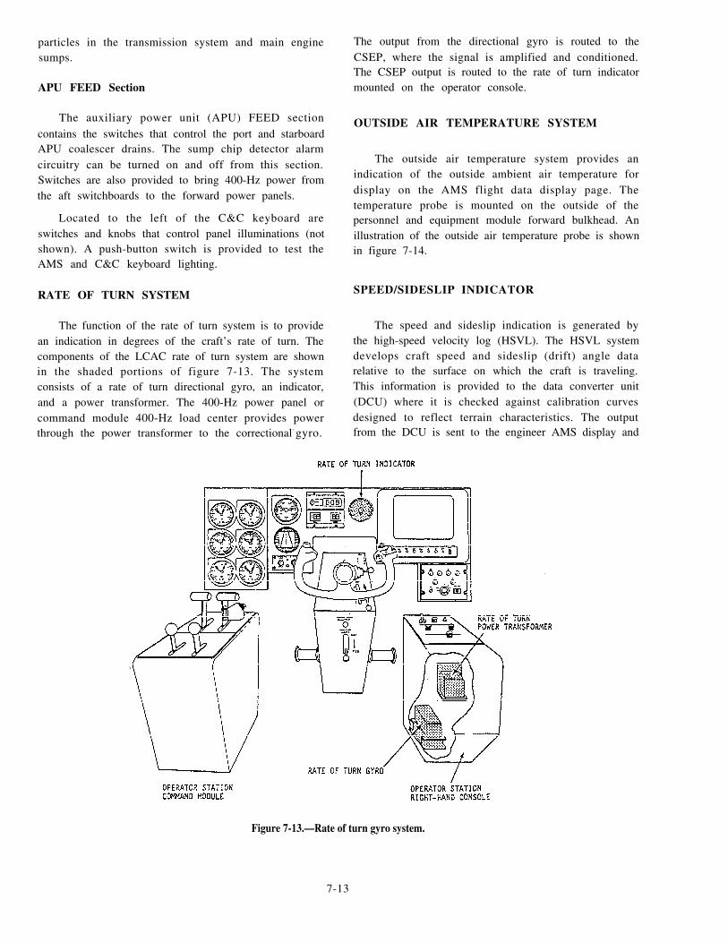
particles in the transmission system and main enginesumps.
APU FEED Section
The auxiliary power unit (APU) FEED sectioncontains the switches that control the port and starboardAPU coalescer drains. The sump chip detector alarmcircuitry can be turned on and off from this section.Switches are also provided to bring 400-Hz power fromthe aft switchboards to the forward power panels.
Located to the left of the C&C keyboard areswitches and knobs that control panel illuminations (notshown). A push-button switch is provided to test theAMS and C&C keyboard lighting.
RATE OF TURN SYSTEM
The function of the rate of turn system is to providean indication in degrees of the craft’s rate of turn. Thecomponents of the LCAC rate of turn system are shownin the shaded portions of figure 7-13. The systemconsists of a rate of turn directional gyro, an indicator,and a power transformer. The 400-Hz power panel orcommand module 400-Hz load center provides powerthrough the power transformer to the correctional- gyro.
The output from the directional gyro is routed to theCSEP, where the signal is amplified and conditioned.The CSEP output is routed to the rate of turn indicatormounted on the operator console.
OUTSIDE AIR TEMPERATURE SYSTEM
The outside air temperature system provides anindication of the outside ambient air temperature fordisplay on the AMS flight data display page. Thetemperature probe is mounted on the outside of thepersonnel and equipment module forward bulkhead. Anillustration of the outside air temperature probe is shownin figure 7-14.
SPEED/SIDESLIP INDICATOR
The speed and sideslip indication is generated bythe high-speed velocity log (HSVL). The HSVL systemdevelops craft speed and sideslip (drift) angle datarelative to the surface on which the craft is traveling.This information is provided to the data converter unit(DCU) where it is checked against calibration curvesdesigned to reflect terrain characteristics. The outputfrom the DCU is sent to the engineer AMS display and
Figure 7-13.—Rate of turn gyro system.
7-13

Figure 7-14.—Outside air temperature probe installation.
to the analog speed and sideslip indicator on the operator
console.
The sideslip analog indication is displayed on the
operator console as a left or right bar movement. (See
fig. 7-15.) The bar movement has zero degrees at the
Figure 7-15.—Operator station sideslip indicator.
center and a maximum travel of 60° to the left and right.The sideslip indication on the engineer AMS display isa digital numeric readout, with alpha characters showingPORT and STARBOARD.
LCAC ELECTRICAL SYSTEM
The electrical power generation for the LCACprovides alternating and direct current requirements forpower and lighting loads on the trail. The APU system,generator set, and its associated auxiliary controlequipment are responsible for the generation of120/208-Vac, 60-kW, 400-Hz, 3-phase power. The craftis organized into primary and secondary powerdistribution. Power is distributed over a common,redundant bus system in a manner that affords maximumprotection form battle damage and equipment failure.Primary power consists of the craft generator 400-Hz acpower and the external shore 400-Hz ac power systems.Secondary power consists of the transformer rectifierunit (TRU) 28-V dc power system, the emergencypower system, and 28-V dc tank power receptacle. Thesecondary 28-V dc system is also distributed over acommon, redundant bus.
AUXILIARY POWER UNIT
As shown in figure 7-16, the gas turbine generatorsets are mounted port and starboard on the LCAC. Eachset consists of an ac generator, air inlet chamber,combustor assembly, turbine assembly, and reductiongear drive assembly. The gas turbine engine is ar a d i a l - f l o w , 1 5 0 - h p , s i n g l e - s t a g e c o m p r e s s o r ,single-stage turbine. The APU is a Turbomach ModelNo. T-62T-40-7. Filtered air within the compartments isused for turbine inlet combustion air and generatorcooling. An enclosure assembly houses each gas turbineengine and provides mounting of the turbine, exhaustconnections, ship pipes, drain connections, andelectrical connections. The access doors provided on theenclosure allow for inspection and maintenance of thegas turbine components.
APU Turbine Engine
The major components of the gas turbine engine arethe generator, turbine, combustor and reduction geardrive. In addition, electrical control devices, accessoriesand associated plumbing and wiring are also part of thegas turbine assembly. The gas turbine incorporates anintegral lubrication system. The lubricating oil iscontained in an integral oil sump on the bottom of thereduction gear and accessory drive housing. A 24-V dc
7-14

Figure 7-16.—Auxiliary powerunit (APU) locations.
7-15

electrical control system provides electrical energy forignition and for operating the electrical components.Although a fuel system is integral to the gas turbineengine, a fuel supply must be connected to the engine.
The APU gas turbine assembly is shown in figure7-17. The APU gas turbine consists of an air inletassembly, rotor assembly, diffuser, turbine nozzleassembly, and input pinion. The air inlet housing is acontoured, cylindrical casting with forward and aft inletflanges. The flanged forward end of the air inlet housingis bolted to an adapter. The adapter is bolted to the aftend of the reduction drive housing. The ail end of the airinlet housing is externally flanged to permit attachmentof the combustor assembly. This configuration allowsthe air inlet housing to serve as a rigid member betweenthe reduction drive assembly and the combustorassembly. An air inlet screen assembly covers the intakeportion of the air inlet housing.
Gearbox Section
The reduction gear and accessory drive assemblyreduces the output rotational speed (61,091 rpm) of therotor assembly to the speeds necessary to drive the APUgenerator and accessories. The two-piece reductiondrive housing is machined from aluminum sandcastings. The reduction drive inlet pinion drives three
planetary gears which, in turn, drive an internallysplined ring gear. The ring gear is centrally splined to ashort output shaft. The external gear of the output shaftdrives the oil pump drive gear. The internal splines ofthe output shaft connect the driven equipment to theengine.
The upper portion of the reduction gear driveassembly contains the accessory drive. The output shafttransmits power through an intermediate gear to the fuelpump drive and starter gears, which convert thereduction gear output speed to 6,000 rpm. This is thespeed required to drive the APU’s accessories. The fuelpump gear operates at 4,200 rpm. With the starterdisengaged, the starter gear is free to rotate with theintermediate gear. When the starter is engaged, thestarter gear drives the accessory drive gear train tosupply the necessary starting torque to the GTE.
The gears and bearings in the accessory drive arelubricated by an air-oil mist from the reduction driveassembly. To prevent the mist from leaking, seals aremounted in the reduction drive housing at the ends ofthe output shaft and the fuel pump drive and startergears. The fuel pump and engine acceleration controlassembly, which is mounted in tandem with the fuelpump, is mounted on the left forward pad of thereduction gear housing. The starter assembly is mountedon the right forward pad.
Figure 7-17.—APU gas turbine engine assembly.
7-16

APU Lubrication System
The APU lub r i ca t i ng o i l sy s t em p rov ideslubrication to the high-speed input pinion, the reductionand accessory gears, and the shafts and bearings. Thisintegral lubrication system consists of an oil pump, afalter, a falter bypass relief valve, a pressure relief valve,an oil pressure switch, an oil distribution ring assembly,and an oil sump. All components of the APU lubricationsystem are contained within the reduction gear andaccessory drive assembly.
A high oil temperature switch is installed in thereduction gear drive. The switch is electricallyconnected to the electronic sequence unit (ESU) toenable the ESU to monitor the oil temperature and shutdown the APU when the oil temperature reaches 275°±5°F.
APU Fuel System
The APU fuel system automatically provides properengine acceleration and maintains a nearly constantoperating speed under all operating conditions. Fuel issupplied to the GTE at 5 to 40 psig with a minimum flowcapacity of 200 pounds per hour. The main componentsof this system are an inlet fuel filter, a fuel pump, anengine acceleration control assembly, start-fuel,main-fuel , and maximum-fuel solenoid valves ,start-fuel nozzle, purge valve, and a manifold assembly.
During the APU start, the start-fuel solenoid valveopens. The resulting fuel pressure forces the piston inthe purge valve to one side in the valve chamber to allowfuel to f low through the s tar t fuel nozzle . Atapproximately 65 percent engine speed, the start-fuelsolenoid valve closes to cut off the fuel pressure. Areturn spring transfers the piston in the purge valve tothe purge position. In the purge position, compressordischarge air flows through the start-fuel nozzle to clearthe nozzle of residual fuel. The residual fuel is thendirected to the combustor to be burned.
Electronic Sequence Unit
The ESU is a control device that monitors APUspeed, turbine exhaust temperature, low oil pressure,s equence f a i l u r e , APU t empera tu r e , and APUunderspeed. The ESU shuts down the APU ifmalfunctions occur in these circui ts . Each 40milliseconds, the ESU checks all functions and confirmsthat input data is greater or lesser than programmedvalues. In the event input data is outs ide theprogrammed values, an indication is provided in the
built-in test equipment (BITE) box assembly and, ifrequired, the engine is shut down.
Generators
The generators driven by the APUs produce a120/208-V ac, 400-Hz, 60-kW, 3-phase current. Thegenerator is a salient-pole, brushless, permanent-magnet type that incorporates a fan and generator airinlet adapter for cooling. The ac voltage generated bythe permanent magnet rotor and stator is connected toan external voltage regulator where it is rectified andregulated. When both generators are operating, the loadis divided, but either generator can supply total craftpower requirements under normal operating conditions.
The control components consist of two governorcontrol units (GCUs), ESUs, current transformers,BITE boxes, an APU start panel, and generator startboxes. The controls are used to monitor operatingconditions for both the engine and generator. Thecontrol components for each gas turbine generator setare mounted in a control enclosure.
Generator Control Unit
A GCU is installed for each ac generator. The GCUcircuits are functionally divided into the power supply,regulator, generator relay controls, contactor relayc o n t r o l s , f e e d e r f a u l t , o v e r v o l t a g e s e n s i n g ,u n d e r v o l t a g e s e n s i n g , u n d e r f r e q u e n c y , a n doverfrequency sensing sections. Each GCU monitorsand controls generator output parameters. The GCUprovides voltage regulation, controls the generatoroutput voltage, and protects the generator fromfrequency and current malfunctions. Generator input
power application and output power regulation isaccomplished by controlling the excitation applied tothe generator by the GCU. The GCU also controls theexcitation to the line contactor that distributes generatorfeeder lines to the load. The GCU also contains featuresthat are used to establish a test mode of operation for thegenerator.
ELECTRICAL DISTRIBUTION
The electrical distribution system aboard the LCACis composed of a 400-Hz/208-V ac system, and a 28-Vdc system. The generators each supply separate 400-Hzswitchboards which serve as central control points forpower distribution. We will take a brief look at these twopower systems in the following paragraphs.
7-17

400-Hz/208-V AC Distribution System
Primary power (400 Hz/208 V ac) is provided nomeither external shore power or the two APU-drivengenerators. Generator power and shore power isdistributed through the craft using the same busses.After the generators are started and power is available,the generators can be placed online by depressing theappropriate switch on the C&C keyboard. The powercontrol relays are energized and route power to the mainline contractors to energize the aft busses, port ands t a r b o a r d . T h e f o r w a r d b u s s e s a r e c o n t r o l l e dautomatically through relay contacts of the linecontractors. An isolation power supply wired betweenthe battery switchboard and the switchboard controlpanels provides isolation between the ac and dc powerdistribution systems.
28-V DC Power Distribution System
All 28-V dc power is provided from two sources:(1) the storage batteries and (2) the transformer/rectifier(T/R) units. The storage batteries are made up of two12-volt batteries connected in series. The T/R unitsconvert 400 Hz/208 V ac to 28 V dc. The 400-Hz loadcenters are energized from the APU-driven generatorsor from 400-Hz external shore power. The No. 1 and No.2 primary dc busses are cross connected through theemergency dc power panels. The reverse current relaysfunction to prevent damage to the T/R units if a T/R unitshould fail. When shore power or generator power isunavailable, the battery serves as the emergency dcpower source.
Now that you have read about the LCAC propulsioncontrol system and the associated components andsystems, let’s look at some important aspects involvingthe maintenance of these systems.
LCAC SYSTEMS MAINTENANCE
As with all equipment and systems, the propulsioncontrol systems and related equipment on the LCACmust be monitored for effective and safe operation.Monitoring these systems is also a way of providingearly warnings concerning potential trouble areas.
In this section, we will talk about the generalmaintenance and troubleshooting routines you willencounter with the LCAC control systems andequipment. For detailed information concerning theprocedures you should use for removing and replacingspecif ic par ts , we recommend you consul t theappropriate technical manuals.
SCHEDULED MAINTENANCE
Scheduled maintenance of the LCAC controlsystems includes the procedures you must perform forpreventive maintenance and performance tests. You willdiscover that you must accomplish these procedures ona scheduled or condition monitoring basis.
Y o u c a n f i n d t h e a p p r o p r i a t e s c h e d u l e dmaintenance actions in the technical manuals for thespecific equipment items. Remember, the scheduledmaintenance instructions in these technical manuals arenot intended to duplicate the instructions furnished inthe PMS. In t he ca se o f con f l i c t s , t he PMSdocumentation takes precedence.
MAINTENANCE REPAIR LEVELS
For the LCAC, the maintenance repair levels aredivided into the following four categories:
1
2
3
4.
Organizational
Enhanced organizational
Depot
Specialized repair facilities
These repair levels are par t of the source,maintenance, and recoverability (SMR) codes for eachpart, subassembly, and module. The SMR codes areidentified and explained in the Coordinated ShipboardAllowance List (COSAL) for the LCAC. Let’s brieflylook at each of these levels.
Organizational Maintenance
Organizational maintenance includes the type ofmaintenance actions that are performed on the LCACcraft, afloat. Organizational maintenance consists of allthe maintenance actions required to maintain theoperational status of the LCAC during deployment.
Enhanced Organizational Maintenance
Enhanced organizational maintenance includes themaintenance actions that are normally performed on theLCAC craft, ashore. This level of maintenance normallyconsists of craft system troubleshooting, componentreplacement, or part manufacturing. The LCAC craftunit, ashore, is normally a complete repair facility. Theonly maintenance actions that are not performed at thisfacility are those that require a depot or specializedfacility maintenance.
7-18

Depot Maintenance
Depot maintenance is normally based at a shorefacility. This level of maintenance involves the repair ordisposition of components, modules, or assemblies thata r e s ea l ed o r r equ i r e ma jo r ove rhau l . Depo tmaintenance also consists of repair procedures that arenot available at the enhanced organizational level andthose that are not cost effective at the lower levels.
Specialized Repair Facility
Specialized repair facility maintenance is normallyaccomplished at a shore facility that has the specializedcapabilities required for specific parts that needmaintenance actions beyond the scope provided by thedepot maintenance level.
Now that we have talked about the differentmaintenance levels , le t’s look at some of thet r o u b l e s h o o t i n g p r o c e d u r e s y o u m a y n e e d i nmaintaining the LCAC control equipment and systems.
TROUBLESHOOTING PROCEDURES
In troubleshooting the components and systems ofthe LCAC, you will use the basic troubleshootingmethodology we discussed earlier in this TRAMAN.Sometimes, system analysis will allow you to godirectly to a specific faulty component or cable. Whenyou need to use a more comprehensive process,however, the half-split method of troubleshooting willprovide you with the most logical approach to faultisolation.
To perform the half-split method of fault isolation,you should first pick a circuit midpoint on a specificwiring diagram. Your ability to gain access to thismidpoint should be the determining factor. By taking asignal measurement at the midpoint, you will be able todetermine which half of the circuit is defective. Afteryou determine a midpoint, refer to the wiring diagramto identify the signal level or range required. If the signalis correct at the midpoint, then the defective part orcircuit lies somewhere between that point and the endof the circuit. If the signal made at the midpoint is notcorrect, the problem lies somewhere between that pointand the point at which the signal starts. Your next stepis to continue to use the half-split method on the part ofthe original circuit you have found to be defective.
You should continue this process until you canisolate the defective part or area. In the last stage of thehalf-split method, you should be able to isolate the faultto a specific component or part of the circuit. At this
point, you should use a voltage and continuity check toconfirm the specific cause of the problem.
In the preceding sections of this TRAMAN, youhave read about the design, control systems, and basicmaintenance you will encounter in your duties andresponsibilities aboard an LCAC. Now, let’s look at thepropulsion system of another type of landing craft, thepatrol combatant missile (hydrofoil) or PHM.
PATROL COMBATANT MISSILE(HYDROFOIL)
The PHM is an advanced design, fast, highlymaneuverable, foilborne warship. The mission of thePHM is to operate offensively against host i le ,heavy-surface combatants and other surface craft and toconduct surveillance operations, such as screeningcoastal convoys or amphibious forces in the arrival anddeparture areas. This small, fast, and versatile shipprovides the Navy with high-speed support capabilities.
The basic design of the PHM is shown in figure7-18. This design offers the stability and ride comfortnormally limited to much larger ships at a much lowercost. It also offers the high maneuverability and speedassociated with smaller vessels. Its propulsion systemconsists of both a foilborne and hullborne system. Thiscombination design offers the advantages of a dieselengine in its economical, long-range cruising andclose-in, low-speed twin-engine maneuvering abilityand those of a lightweight GTE in its immediate,high-speed foi lborne capabil i t ies . I ts maximumhullborne range is greater than 1,200 nautical miles witha maximum speed of 11 knots. While the craft’s takeoffspeed is dependent on the loading, sea state, and powersettings of its controls, its maximum foilborne speed isgreater than 40 knots with a maximum cruising range ofgreater than 500 nautical miles.
As we discuss the PHM, we will provide you witha general description of the physical and functionalcharacteristics of its propulsion systems and controllingstations. The basic control system includes the systems,controls, and equipment needed for direction, speed, andother maneuvering operations. Its propulsion andauxiliary systems include the following six subsystems:
1
2
3
4
5
Main propulsion (foilborne) subsystem
Main propulsion (hullborne) subsystem
Power train subsystem
Automatic control subsystem
Electrical subsystem (ship’s service power unit)
7-19

Figure 7-18.—Patro1 combatant missile (hydrofoil) (PHM).
6. Auxiliary subsystems
In the following paragraphs, we will brieflydescribe these systems and how they work to propel andcontrol the craft.
PROPULSION SYSTEMS
The PHM has two complete and separate main
propulsion systems: (1) the foilborne system and (2) thehullborne system. As its name implies, the foilborne
propulsion system propels the ship in the foilbornemode. In addition, the foilborne system can propel theship in the hullborne mode, either with the foils extendedor retracted. The hullborne propulsion system, however,can propel the ship only in the hullborne mode, eitherwith the foils up or down. The machinery arrangementfor both the foilborne and hullborne propulsion systemsis shown in figure 7-19.
Both foilborne and hullborne operations arecontrolled from a common helm. When the PHM is in
7-20
the hullborne mode, a water jet nozzle pivots in responseto an operator command from the helm to provide
steering and reversing functions. A bow thrusterprovides for close-in maneuvering and docking.Consequently, the hullborne mode is used for any type
of close maneuvering, such as docking or reversing thecraft’s direction. When the craft is in the foilborne mode,
a control system consisting of the helm, throttle, and anautomatic control system (ACS) provides continuousdynamic control during all foilborne operations. By
providing trim and attitude control, automatic bankingin turns, and seaway disturbance alleviation, thefoilborne control system makes it possible for the PHM
to achieve its desirable riding qualities and fast speeds.The foilborne control surfaces include the trailing edgeflaps on each of the foils and the swiveled forward strutwhich acts as a rudder. (See fig. 7-19.) In the following
paragraphs, we will get a closer look at both thehullborne and foilborne propulsion systems. Let’s firstlook at the foilborne system.

Figure 7-19.—Main machinery arrangement for foilborne and hullborne propulsion systems.
Figure 7-20.—Foilborne propulsion system.
MAIN PROPULSION (FOILBORNE) propulsion is created by a two-stage water jet pumpSYSTEM powered by a gas turbine engine. The propulsion thrust
The foilborne propulsion system provides the PHM occurs as seawater is pumped through the water jets and
with speed and stability. The basic components of the expelled through a nozzle at the stern. The reactive force
foilborne propulsion system are shown in figure 7-20. resulting from the acceleration and expulsion of the
The foilborne power plant supplies the thrust required seawater drives the ship forward. The main advantagefor takeoff and foi lborne operat ions . Foi lborne of this system is its speed and efficiency in driving the
7-21

craft forward. When foilborne, the PHM can attainspeeds greater than 40 knots. A disadvantage, however,is that there is no provision for reversing the craft whenthe PHM is in the foilborne mode.
The basic foilborne propulsion system consists ofthe GTE (power plant), a power train assembly, and apropulsor assembly. In the following sections, we willexamine the main components of the foilborne system,starting with its power plant, the LM2500 GTE.
LM2500 GTE ASSEMBLY
The power for the foilborne system is provided bya General Electric LM2500 GTE located in the gasturbine machinery room. This GTE is the same type thatis used in the twin-shaft and single-shall ships. The gasturbine assembly consists of a gas generator, a powerturbine, a high-speed coupling shaft, and an exhaustduct. At 100 percent power, this GTE is capable ofdelivering 16,767 hp to the gearbox assembly at about3,100 rpm.
The LM2500 GTE draws combustion air throughknit-mesh filters located on the weather deck. Thecombustion air flows through the demister panels andthe air intake plenum, which interfaces with the forwardend to the gas turbine machinery room. A barrier walland seal prevent any air from the area surrounding theengine from entering the combustion air intake. Theexhaust gases flow from the GTE exhaust duct throughprimary and secondary eductor nozzles, which create aflow of secondary cooling air through the gas turbinemachinery room. Located in the aft end of the gasturbine machinery room is the foilborne engine exhaustcollector. When the GTE is running, the exhaust workslike an eductor to draw cooling air into this compartmentfrom ventilation ducts through the auxiliary machineryroom No. 1. When the GTE is secured, fans on eitherside of the combination air inlet finish cooling air forthe engine and its compartment. The exhaust gaseseventually exit through the foilborne engine exhauststack located just aft of the superstructure.
In addition to the LM2500 GTE, the gas turbinemachinery room contains other foilborne propulsionsystem equipment, including the foilborne engine lubeoil supply and return falters, engine lube oil-to-fuel heatexchanger, engine fuel heater, propulsor gearbox lubeoil-to-engine fuel heat exchanger for operating in coldareas, and propulsor gear lube oil-to-engine lube oil heatexchanger for operating in hot areas.
Lube Oil System
The LM2500 GTE lube oil system provides twomain functions: (1) it supplies cool oil to the gas turbinebearings, gears, and splines to prevent excessive frictionand heat, and (2) it supplies heat through the oil-to-fuelheat exchanger to heat the fuel for the gas turbine. Thelube oil is stored in a 7.2-gallon oil tank located over theengine. The oil is gravity-fed from the storage tank tothe lube and scavenge pump mounted on the gas turbine.The single-supply element of the pump forces the lubeoil through tubes to the specific areas requiringlubrication.
A duplex filter mounted beneath the engine on thestarboard side provides filtration for the supply oil. Aduplex filter mounted beneath the engine on the port sideprovides filtration for the scavenge oil. The scavenge oilhousing assembly contains a magnetic chip detector.The scavenge oil is filtered, cooled, and returned to thestorage tank.
Fuel Oil System
The GTE fuel system on the PHM is essentially thesame as the fuel systems on other gas turbine-poweredships. The PHM fuel system regulates and distributesfuel to the combustion section of the gas generator,providing a control over gas generator speed. Althoughthe power turbine speed is not directly controlled by theGTE fuel system, it is established by the gas streamenergy level produced by the gas generator.
Operation
The GTE is started by the operator in the engineer’soperating station (EOS). Throttle control then istransferred to the helm (pilothouse) for foilborneoperation. During foilborne operation, the monitoringof operating parameters continues to take place in theEOS. Before the GTE is shut down, control istransferred back to the EOS where the GTE is shut downby automatically controlled logic. Auxiliary functions,such as the GTE machinery room cooling, compressorwashing, and engine waste drain pumping, arecontrolled by the operator in the EOS.
There is no local control at the GTE. The EOSoperator normally starts and stops the GTE by using theautomatically controlled sequencer. In case of systemmalfunction or damage to the GTE, however, manualstarting and stopping of the engine can be accomplishedat the EOS control console.
7-22

The GTE drives the propulsor assembly by meansof the power train assembly. We have already talkedabout the LM2500 GTE that provides the power for thefoilborne propulsion system. Now, let’s take a look atthe propulsor assembly for this system.
PROPULSOR ASSEMBLY
The foilborne propulsor consists of a two-stageAerojet Liquid Rocket waterjet pump, a bearing, and aseal assembly. The Aerojet pump forces seawater upthrough the two ducts in the two aft foil struts into asingle foilborne water jet nozzle that exhausts theseawater through a transom at the hullborne waterline.(See figs. 7-19 and 7-20.) The frost stage of the waterjetpump operates at a lower speed for good suctionperformance. The second stage runs at a higher speed toincrease pressure and velocity. The propulsor assemblyis driven by the GTE through the gearbox assembly or
power train, which we will discuss next.
POWER TRAIN ASSEMBLY
The power train assembly consists of the gearbox,flexible coupling, and shaft assemblies. The GTE drivesthe gearbox through a high-speed flexible couplingshaft. This shaft is designed to accommodate any axialor radial movement between the GTE and gearbox thatresults from dynamic loads and thermal expansion.Because the GTE is directly coupled to the propulsorthrough the gearbox, there is no disengagementcapability. This means that whenever the GTE isoperating, the propulsor is being driven.
Gearbox Assembly
The gea rbox a s sembly i s a Wes t e rn Gea rlightweight, reduction transmission unit that sendspower from the GTE to the foilborne propulsor throughthe bearing and seal assembly. The gearbox is splitvertically into a high-speed assembly and a low-speedassembly and consists of main drive pinions that drivetwo coaxial output shafts through two sets of doublehelical reduction gears. This design allows it to providespeed reduction and power split to the two propulsorimpellers. It does this by reducing the input speed fromthe GTE and providing separate output shafts to thepropulsor first-stage inducer and the second-stageimpeller, allowing these two sections to operate atdifferent speeds. An access hole in the high-speedassembly and one in the low-speed assembly provide ameans for inspection. The gearbox assembly alsoprovides four hydraulic pump accessory drive pads as
well as the drive pads for the lube oil supply andscavenge pumps. Eight thermocouples, one in eachmain bearing, monitor bearing temperatures.
Flexible Coupling and Shaft Assemblies
A double-diaphragm flexible coupling connects thelow-speed and high-speed pinion shafts. Each coaxialoutput shaft consists of an inner high-speed quill shaftand an outer low-speed quill shaft. Splines in thehigh-speed and low-speed output gears drive the outputshafts.
FOILBORNE CONTROL SYSTEMS ANDOPERATING STATIONS
The foilborne control systems include all thesystems that allow a PHM in the foilborne mode torespond to control commands. These systems includethe ACS, foilborne engine control system (FECS),foilborne propulsor control system (FPCS), and thebulkhead-mounted electronics enclosure (BMEE). Thefoilborne control systems also include the foilborneequipment and systems found in the foilborne controlstations, such as the EOS and the pilothouse.
Pilothouse
Foilborne operation is primarily controlled from thepilothouse. The pilothouse control console, which isshown in figure 7-21, is designed for a two-manoperation under normal conditions. The helmsman isseated on the right with the primary maneuveringcontrols and displays arranged on the console within hisor her reach. The displays necessary for conning andmonitoring the ship are grouped on the left in front ofthe OOD seat. Overhead panels, which can be reachedfrom either seat, contain the controls and indicator lightsfor cr i t ical ship’s systems and the windshieldwasher/wiper controls.
Engineer Operating Station
The EOS is located on the port side of the platformdeck adjacent to the gas turbine machinery room andturbine inner intake plenum. Although a seat is availablefor a second operator or for training purposes, the EOSis basically arranged for a one-man operation.
The EOS control panel arrangement is shown infigure 7-22. The power plant controls are on the mainconsole. The electrical and fuel controls are on theinboard cabinet . The hydraulic panel is placeddiagonally at the corner. A more detailed view of a
7-23

Figure 7-21.—FBCS controls at the pilothouse control console.
Figure 7-22.—Engineer operating station (EOS) showing panel arrangement.
7-24
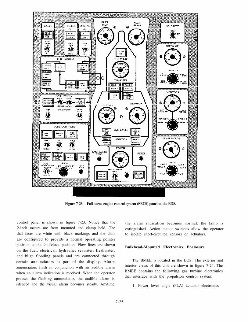
Figure 7-23.—Foi1borne engine control system (FECS) panel at the EOS.
control panel is shown in figure 7-23. Notice that the the alarm indication becomes normal, the lamp is2-inch meters are front mounted and clamp held. The extinguished. Action cutout switches allow the operatordial faces are white with black markings and the dials to isolate short-circuited sensors or actuators.are configured to provide a normal operating pointerposition at the 9 o’clock position. Flow lines are shown
Bulkhead-Mounted Electronics Enclosureon the fuel, electrical, hydraulic, seawater, freshwater,and bilge flooding panels and are connected through
The BMEE is located in the EOS. The exterior andcertain annunciators as part of the display. Alarminterior views of this unit are shown in figure 7-24. Theannunciators flash in conjunction with an audible alarmBMEE contains the following gas turbine electronicswhen an alarm indication is received. When the operatorthat interface with the propulsion control system:
presses the flashing annunciator, the audible alarm issilenced and the visual alarm becomes steady. Anytime 1. Power lever angle (PLA) actuator electronics
7-25

2
3
4
5
Figure 7-24.—Bulkhead-mounted electronics enclosure (BMEE).
Torque computer electronics the BMEE, maintains the ship’s +28 V dc input at a
Speed and acceleration electronicsconstant potential under loads to 30 amperes. The ship’s+28 V dc feeds the BMEE, FECS, and FPCS panels
Overspeed switch electronics from a circuit breaker located on either one of the two
Start/stop sequencer electronics dc distribution panels.
Let’s take a brief look at how these electronics Foilborne Control Systeminterface with each other and with the propulsion controlsystem. The foilborne control system (FBCS) controls the
The PLA actuator, which is mounted on the mainPHM during foilborne operations and during transitions
fuel control of the GTE, receives signals from thebetween foilborne and hullborne operations. The FBCS
BMEE torque computer electronics. A voltage booster,consists of the following equipment and systems:
which is mounted on the aft bulkhead of the EOS below 1. Automatic control system (ACS)
7-26

2
3
4
5
6
Ready and warning system
Heading hold system
Foilborne throttle system
Forward and aft hydrofoils
Bow doors
The FBCS also monitors several critical parametersof the foilborne system and provides visual (and someaudible) warnings of unsatisfactory conditions. Aself-test feature is available in most sections of theFBCS. The major systems of the FBCS that allow thePHM helmsman to monitor and control foilborneoperations are the ACS, the FECS, and the FPCS. In thefollowing paragraphs, we will take a look at someexamples of how these systems work.
AUTOMATIC CONTROL SYSTEM.— The ACScontrols the PHM during takeoff, landing, and allfoilborne operations. By automatically positioning thefoilborne control surfaces, such as the forward flap, portand starboard flaps, and forward strut, in response tosensed ship motion and manual commands from thehelm, the ACS provides attitude control, stability, andoperation in rough water. The ACS also provides aself-test capability to allow the operator to performsystem operational tests and fault isolation procedures.
The heart of the ACS is the control computer thatreceives command inputs and sensor inputs, performsthe necessary logic, and processes the proper controlsignals to the proper control surfaces. It also receivesfeedback signals from the position transducer in thecontrol surface actuators. Command inputs consist ofheading change (turn) signals from the helm and foildepth command signals from the ACS control panelassembly. Sensor inputs are from attitude sensors
(gyros), foil depth sensors (height sensors), and heavesensors (accelerometers).
The ACS electrical power assembly consists of anACS power supply assembly, an ACS inverter, a dc linecontactor, an ac line contactor, an isolation transformer,and blocking diodes. As shown in figure 7-25, thesecomponents are all mounted to the top shelf of the shipcontrol electronics installation. The ACS power supplyassembly input is 115 V ac, 400 Hz from either the ACSinverter, which is powered by +28 V dc (from two dcpanels for redundancy) or from ship’s 115 V ac, 400 Hzthrough an isolation transformer. The +28 V dc is thesystem’s primary source with the ship’s 115 V ac as thebackup source. Circuits within the ACS power supplyas semb ly mon i to r t he i ncoming power a t t hechangeover relay and provide for switching from
Figure 7-25.—Ship control electronics installation showing ACS.
primary to backup power when a loss of primary poweroccurs.
Let’s look at how this system works. Once thehelmsman sets the foil depth level command, the ACSmaintains the appropriate depth during all shipmaneuvers and throughout all sea conditions. As thehelmsman rotates the helm for a heading change, theACS adjusts the f laps and forward s t rut for acoordinated turn. When the helmsman adjusts thefoilborne throttle to control the ship’s speed, the ACS
accommodates the resulting hydrodynamic forces thatchange during the ship’s change in speed by adjustingthe ship’s pitch angle and the foil’s angle of attack tomaintain the required lift. The helmsman can set theACS MODE switch at the helm station to STRUTSTEERING. This will activate a portion of the ACS andthe forward strut steering circuits, allowing thehelmsman to steer with the forward strut while the craftis hullborne.
F O I L B O R N E E N G I N E C O N T R O LSYSTEM.— The FECS provides for automatic startingand stopping of the GTE and the gearbox auxiliary lubeoil pump. With the mode selector switch in the auxiliary
7-27

(AUX) position, the helmsman can obtain manualcontrol of some of these functions by using theindividual control switches. Functions that can becontrolled manually are engine compressor washing,engine waste drain transfer, demister panel anti-icing,engine secondary cooling air, engine fuel shutoff valvetest, engine fuel system purging, engine fuel heating,starting air compressor activation, gearbox lube oilheating, and system self-tests. The detailed view of theEOS panel shown in figure 7-23 is an FECS panel.Notice the dial faces and how the indicating and warninglights and temperature and pressure gauges are providedfor monitoring foilborne operations. The circuit cardsused in the FECS have LEDs and test points on the edgesfor troubleshooting.
As mentioned earlier, the GTE is started by theoperator in the EOS. Then, throttle control is transferredto the helm for foilborne operation. Before shutdown,control is transferred back to the EOS where the GTE isshut down with automatically controlled logic.
F O I L B O R N E P R O P U L S O R C O N T R O LSYSTEM.– The FPCS consists of a GTE, a WesternGear gearbox, an Aerojet Liquid Rocket propulsor
assembly, and an ELDEC propulsion control system.Interfacing support systems include the gas turbine inletand exhaust air systems, secondary cooling air, airstarting (pneumatic) system, and electrical power.
Although control for the gearbox auxiliary lube oilpump is contained in the FECS, manual control for thelube oil tank heater is provided on the FPCS panel, asshown in figure 7-26. Indicating and warning lights andtemperature and pressure gauges are provided formonitoring propulsor system operation. Test points areprovided on the edges of the FPCS circuit cards.
FOILBORNE OPERATIONS
From reading the preceding sections on the maincomponents and control systems of the foilbornepropulsion system, you have likely deduced how theequipment units and control systems work together tostabilize and propel the craft forward. Basically,foilborne propulsion is achieved through the interactionof hydrodynamic forces similar to the aerodynamicforces in flying. To understand the interaction ofhydrodynamic forces involved in the propulsion of thePHM, let’s take a look at some normal events.
Figure 7-26.—Foilborne propulsor control system (FPCS) panel.
7-28

The FBCS senses the manual inputs from thehelmsman (pilothouse) as well as those monitored bythe ACS, such as roll, pitch angle, yaw rate, verticalacceleration, height of the bow above the surface of thewater, and other measurements associated with themotion, direction, and weight of the ship and the seaconditions. The FBCS then converts these inputs to theappropriate control-surface deflections to providecontinuous dynamic control of the ship.
In general, foilborne control is accomplishedthrough operator and control system inputs, causing theFBCS to position the control surfaces, such as thetrailing edge flaps on the forward and aft foils, and toswivel the forward strut. Each control surface and theforward strut are controlled by separate electrohydraulicactuators. For example, the port and starboard flapsegments on each hydrofoil will operate simultaneously.The flaps on the forward and aft foils will move up anddown differentially to give pitch and foil depth control.Differential movement of the flaps on the two aft foilswill allow the craft to accomplish roll control (banking).For example, port flaps up and starboard flaps down willcounter a ship roll to starboard. Along with roll controlcapability (banking), steering of the forward strut willprovide the craft with directional heading control.
TROUBLESHOOTING THE FOILBORNEPROPULSION SYSTEM
In troubleshooting the foilborne propulsion system,you will be mostly concerned with isolating faultswithin the control systems. Let’s look at some of theprocedures you may be required to use when you aretroubleshooting the different FBCSs.
ACS Procedures
We mentioned earlier that the foilborne ACS wasequipped with self-tests. All ACS troubleshootingprocedures are derived from test failures of the ACSoperational self-tests. The BITE will enable you to faultisolate a high percentage of ACS failures within a highdegree of probability.
Regarding ACS troubleshooting procedures, youshould be especially aware of the ACS power supply andany special conditions you may encounter. For example,if another ACS component fails so that its power inputis shorted, the microbuses for that specific power in theACS power supply will be blown. This condition willresult in a failure of the ACS power supply. Your use ofthe correct fault isolation procedures will likely preventthe possibility of a random double failure of this type.
Nevertheless, you should be aware of this possibilitywhenever you are troubleshooting the ACS.
FBCS Procedures
In troubleshooting the FBCS, the best method youcan use to perform fault isolation techniques is to usedeductive reasoning, experience, instructions, panelindications, and the BITE. You should use the followingprocedures for troubleshooting the FBCS:
1
2
3
4
5
6
Identify the trouble symptom.
Locate the trouble symptom in the system faultdirectory.
Note the probable causes of failure.
Perform the specified corrective procedures.
Heed all precautions and warnings.
When a specified procedure recommendscomponent replacement as a corrective action,refer to the removal/installation section of theappropriate technical manual.
You have just read about the foilborne propulsionsystem and how it provides for speed, handling, andpropulsion of the PHM. In the following paragraphs, wewill take a look at the other PHM main propulsionsystem, the hullborne system.
MAIN PROPULSION (HULLBORNE)SYSTEM
The hullborne propulsion system provides the PHMwith the capability of steering, reversing, docking, andother operations requiring close-in maneuvering. Thehullborne propulsion system consists of both a port andstarboard unit.
The principles of operation for the hullborne systemare very similar to those of the foilborne system. In eachhullborne propulsion unit, the rotational speed of thediesel engine is reduced by the gearbox and transmittedto the propulsor assembly. Working together, both portand starboard hullborne propulsion units can propel thecraft in the hullborne mode at speeds up to 11 knots.
MAJOR ASSEMBLIES
Each of the two hullborne plants is made up of threemajor components: (1) a diesel engine, (2) a speedreduction gearbox, and (3) a water jet pump that acts asthe propulsor assembly. Let’s take a brief look at themost important design features of these components.
7-29

Diesel Engine
Each hullborne propulsion unit is powered by itsown Mercedes-Benz Model 8V331TC81 diesel engine.The diesel engine for each unit is located in the dieselpump and machinery room. Combustion air for thediesels and cooling air for the diesel pump andmachinery room are drawn into the space through ascreened compartment inlet located in the forward endof the air trunk. As the diesels draw combustion air fromthis compartment, the air goes through the screens andfilters and enters the diesel engines. Diesel engineexhaust gases are collected and vented up and outthrough the inside of the compartment inlet.
Reduction Gear
The reduction gear assembly for each hullbornepropulsion unit is built into the diesel engine for that
unit. The speed reduction gearbox drives the propulsorassembly through an overrunning clutch assembly.
Propulsor
The hullborne propulsor assembly draws seawaterfrom a sea chest, accelerates the water, and expels itthrough a nozzle at the stem. The hullborne propulsorinlet is a rectangular bellmouth type of penetration in thehull dead rise to which the propulsor is directly attachedThe propulsor and inlet ducts are located in the auxiliarymachinery room.
Now that you have read about the main componentsof the hullborne propulsion system, let’s take a look atits control system and subsystems.
HULLBORNE CONTROL SYSTEM
Whenever the PHM is in the hullborne mode, thecraft is controlled by the hullborne control system
Figure 7-27.—HBCS controls at the pilothouse control console.
7-30

(HBCS). The HBCS consists of the following threesubsystems:
1. Hullborne steering system
2. Heading hold system
3. Hullborne throttle system
Operation of the HBCS takes place almost entirelyfrom the pilothouse, as shown in figures 7-27 and 7-28.The only HBCS controls located in the EOS are thethrottle assembly and the throttle transfer moduleassembly. These assemblies are used in conjunctionwith the foilborne control system. Let’s take a brief lookat the three subsystems of the HBCS.
Hullborne Steering System
The hullborne steering system provides directionalcontrol and maneuvering capability while the PHM isin the hullborne mode. The location of each majorequipment item in the hullborne steering system isshown in figure 7-28.
Primary steering control is provided by a hydraulicactuator that vectors the hullborne steering nozzles inresponse to position commands from the helm.Additional directional control is provided by the thrustreversers on the hullborne propulsory. A bow thruster isincluded in this system to allow for improved low-speedmaneuverability and to assist in docking. The capabilityfor strut steering is also included in this system. In thefoils down mode, for example, the forward strut can beswiveled for hullborne steering.
Heading Hold System
The heading hold system provides the PHM withthe capability of automatically maintaining a presetheading while the craft is in either the hullborne orfoilborne propulsion mode. The helmsman establishesa preset heading command. A heading error signal isdeveloped as a difference occurs between the craft’sgyrocompass and the preset heading command from thehelmsman. A steering correction signal is then appliedto the ACS or hullborne steering system.
Figure 7-28.—Hullborne steering system equipment.
7-31
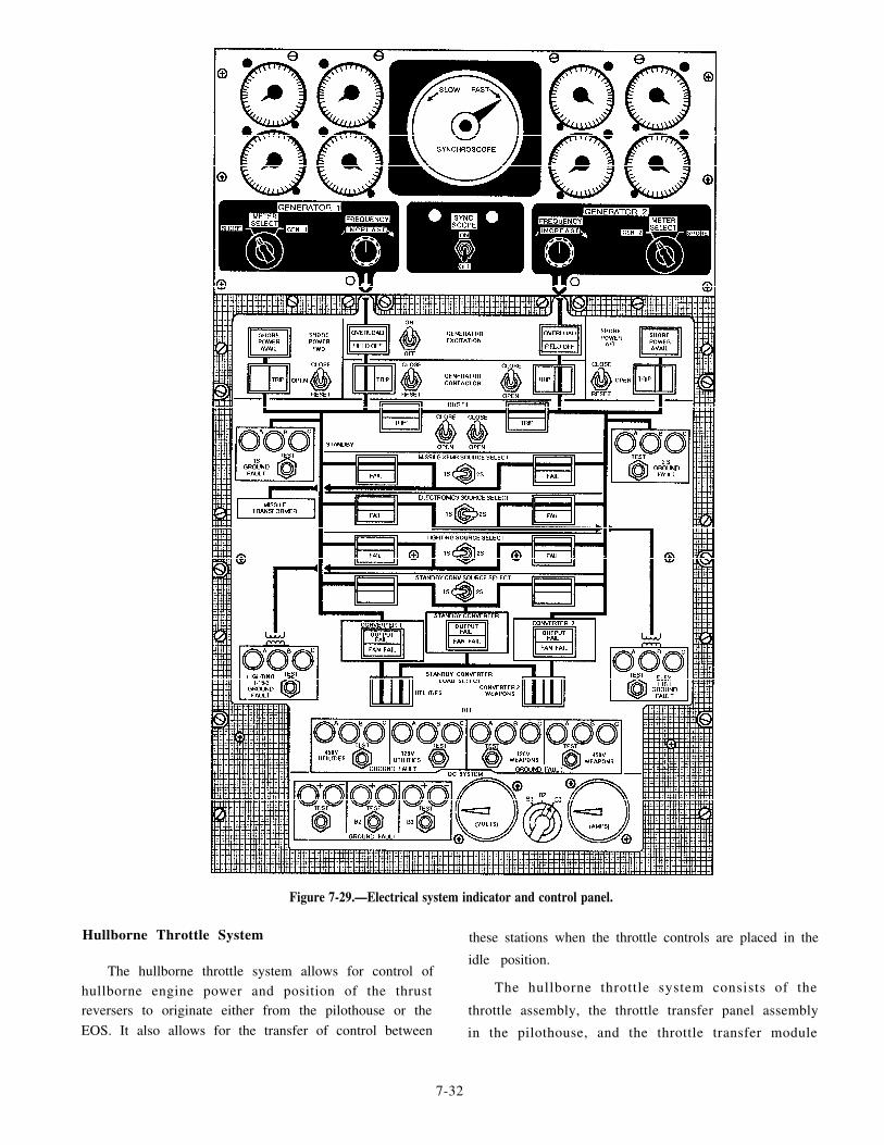
Hullborne Throttle System
Figure 7-29.—Electrical system indicator and control panel.
these stations when the throttle controls are placed in the
idle position.The hullborne throttle system allows for control of
hullborne engine power and position of the thrust The hullborne throttle system consists of the
reversers to originate either from the pilothouse or the throttle assembly, the throttle transfer panel assembly
EOS. It also allows for the transfer of control between in the pilothouse, and the throttle transfer module
7-32

assembly in the EOS. The throttle assemblies at eachstation are identical except for paint color and theguarded ENGINE-OFF switch, which is located only inthe pilothouse unit. The throttle assemblies operate inconjunction with the throttle panel assemblies at eachstation. This feature allows the HBCS to transfer controlof the engines between the helm station and EOS.
You have just read about the hullborne propulsionsystem. Earlier in this chapter, you read about thefoilborne propulsion system. In the following section,we will discuss the PHM electrical system that allowsboth main propulsion systems to work.
PHM ELECTRICAL SYSTEM
The PHM electrical system generates, distributes,and controls the craft’s onboard electrical power. Two450-V ac, 400-Hz, 3-phase brushless generators supplypower to the craft’s electrical equipment. Thesegenerators are driven by power supplied by the ship’sservice power units (SSPUs). Switchboards anddistribution panels distribute and control the electricaloutput. Transformers, converters, and inverters converta portion of the generator output to lower ac and dcvoltages to supply the lower voltage equipment needs.Four shore power receptacles, two for 400-Hz and twofor 60-Hz power, are provided to receive power fromshore installations or other ships upon need.
Basic control of the generators is at the EOS, withemergency controls and voltage/amp meters providedon each switchboard. As shown in figure 7-29, the EOSconsole contains the electrical system indicator andcontrol panel that displays the voltage, amp, frequency,and kilowatt output of each generator. This panel alsoprovides the switches to control and test the entireelectrical system associated with the output of eachindividual generator. A dc voltmeter and dc ammeter formonitoring voltage and current are included on thispanel. Ground fault detection lights and test switches onthe panel provide a means of monitoring circuitcondition.
Two battery chargers supply the normal dc powerrequirements for the craft. They also provide the voltagerequired to maintain the three emergency power batterysets at a specified charge level. Battery power is usedfor normal SSPU and diesel engine starts. The batteriesalso supply normal dc power for various control circuits,indicating circuits, and dc fuel pumps. The batteries arealso used as an emergency power source to supplyemergency loads after an ac voltage failure. Foremergency power, the primary source is voltage
7-33
supplied from the two battery chargers paralleled withthe three battery sets. A secondary emergency powersource is dc voltage supplied from two diesel enginealternators.
SHIP’S SERVICE POWER UNITS
The two SSPUs that supply power to the generatorsand other PHM electrical equipment are installed innonadjacent auxiliary engine compartments. The majorcomponents of an SSPU are shown in figure 7-30. EachSSPU includes a turbine engine and a mechanicalgearbox. Each SSPU must supply the power to drive anac generator, two hydraulic pumps, and a loadcompressor, all of which are mounted on the gearbox.Each SSPU is installed by means of a 3-point suspensionand is attached to the ship’s structure by means ofresilient mounts. These mounts are composed of bondedelastomer spool pieces secured in trunnion blocks.
Normal SSPU control is maintained from the SSPUpanel located in the EOS. The PHM electrical systema l lows t he SSPUs to ope ra t e i nd iv idua l l y o rsimultaneously. When both SSPUSs are operating, each200-kVA, 400-Hz alternator shares the ship’s electricalload. Each SSPU is capable of supplying the PHM’stotal electrical load. Reduction in electrical load,however, is necessary for an SSPU to start the LM2500GTE.
Now that you have read about the general purposeand assembly of an SSPU, let’s take a closer look atsome of its main components.
Figure 7-30.—Ship’s service power unit (SSPU).

SSPU Turbine Engine
The SSPU turbine engine is composed of four majorparts: (1) a 2-stage centrifugal-flow compressor, (2) a3-stage axial-flow turbine, (3) an inlet plenum assembly,and (4) a combustion system. Figure 7-31 is a cutawayview of an SSPU turbine engine showing the relativeposition of each of these components.
The compressor impellers and three turbine wheelsare locked together by means of curvic couplings. A tiebolt through the center of the wheels makes thisassembly a single rotating unit. A floating ring journalbearing and seal assembly on each end of the shaftsupport this rotating unit.
Outside air is drawn into the compressor through theinlet plenum into the combustor where it is mixed withfuel. The fuelhir mixture is ignited by the igniter plugat 10 percent of engine speed. When the unit reaches 95percent of engine speed, the ignition system isautomatically de-energized because at this pointcombustion is self-sustained. The hot gases pass fromthe combustion chamber into the torus assembly. Thetorus assembly directs the hot gases onto the threeturbine wheels. By imparting energy to the turbinewheels, the hot gases cause them to rotate and provideshaft power for operation of the compressor, gearboxassembly, and driven equipment. The spent gases areexpelled through the tail pipe into the PHM exhaustduct.
Figure 7-31.—Cutaway view showing main components of anSSPU turbine engine.
Gearbox Assembly
The external gearbox assembly provides for two ofthe SSPU’s mount pads and the mounting area for theSSPU’S power section. The internal gearbox assemblycontains the reduction gearing that enables the powersection to drive the supporting accessories and theloading components at the proper speed. When thepower section is operating at 100 percent speed (41,730rpm), the unit’s gears provide the following outputspeeds:
Generator 8,000 rpm
Load compressor 8,000 rpm
Hydraulic pumps 3,600 rpm
Lubrication System
The SSPU lubrication system provides lubricationfor the engine and gearbox assembly, load compressor,and generator. It is a full pressure, wet sump systemconsisting of the oil pump assembly, oil falter assembly,oil pressure regulator, and a check valve. The system isalso equipped with pressure and temperature switchesand a temperature sensor for readouts on the PHMindicators. The oil sump is an integral part of the SSPUassembly. The oil sump has a capacity of 8 gallons andis equipped with a drain fitting, a dip stick, and a sightglass for monitoring oil quantity. The SSPU lubricationsystem is serviced through a filler cap. The filler capshould be removed only when the SSPU is shut down.The oil level should be checked daily.
Fuel System
The SSPU fuel system automatically regulates fuelflow to maintain constant engine speed and safeoperating temperatures under varying conditions ofstarting, acceleration, and load application. If the fuelsupply pressure decreases to 4 psig, a LOW FUELPRESSURE indicator on the EOS panel will illuminate.
Control Panel
The control panel for each SSPU is located in theEOS. This panel is divided into three sections, as shownin figure 7-32. The top section provides switches forSSPU de-icing and engine wash functions. The centersection provides meters to indicate the operating oiltemperature, oil pressure, exhaust gas temperature, andpercent speed of each SSPU engine. Filter assemblies,located on the side of the center panel, are used to filterelectromagnetic interference (EMI) generated in the
7-34

Figure 7-32.—SSPU control panel.
exhaust gas temperature meter t ransducers andtransmission lines. The panel lower section providesswitch controls to start, run, and stop both engines. Thissection also contains fault indicators that illuminate todisplay the cause of the fault if an operating fault shouldoccur.
Local Control Panel
The SSPU local control panel is shown in figure7-33. The local control panel is located in the same spaceas the SSPU and allows operation of the SSPU from thatlocation under emergency conditions. The SSPU localcontrol panel includes a LOCAL/EOS switch. The localoperator can use this switch to select where SSPUoperational control will take place. The SSPU local
Figure 7-33.—SSPU local control (emergency) panel.
control panel also includes a master switch forSTART/STOP/RUN operations and a dc circuit breaker.Also located on the SSPU local control panel is an hourmeter to record the elapsed time the turbine has beenrunning. The start counter records the number of starts.
AC GENERATORS
Each SSPU drives its own ac generator. The two acgenerators driven by the SSPUs are brushless, 250-kVAunits that produce 450-V ac, 400-Hz, 3-phase power.Each generator consists of three machines (generators)in one housing. Two of these machines are 3-phasesalient-pole synchronous units (alternators). The thirdmachine is a permanent-magnet, high-frequency (4,800Hz at 8,000 rpm), single-phase unit that provides a lowpower output used for initial excitation and controlcircuits.
The main generator is a rotating-field unit thatdevelops the 400-Hz, 3-phase power supplied to theoutput terminals. Excitation of the main field of the maingenerator is received from the second 3-phase generator.The second 3-phase generator is an acting exciter thatprovides ac voltage. The ac voltage is rectified to dc
7-35

voltage by rotor-mounted silicon diodes and capacitors.The generator is driven at a constant speed through asplined shaft that connects the unit to the SSPU gearbox.
The main generator provides its own internalcooling. Compartment air is drawn in at the generatoroutboard end. An external shroud collects the air androutes it out of the compartment.
GENERATOR CONTROL UNIT
A GCU is installed in each switchboard to monitorthe corresponding ac generator output. The GCUmonitors ac generator output to provide voltageregulation and control and to protect the generator andits electrical load. The GCU provides these functionsthrough sensing, time delay, logic, and output controlcircuits. These functions are mostly contained on eightprinted circuit boards (PCBs). The PCBs are mountedwithin a natural convection ventilated enclosure. Theyare connected to the switchboard wiring by means oftwo multiple pin connectors.
The GCU regulates the generator output voltage bycontrolling the amount of power delivered to thegenerator exciter field. It also protects the electrical loadb y m o n i t o r i n g t h e g e n e r a t o r o u t p u t f o rover /undervol tage, overcurrent , underfrequency,
over/underexcitation, and differential phase currents forboth single and parallel operation. In its monitoringfunction, the GCU activates control circuits to isolatethe faulty output from the ship’s electrical distributionsystem.
ELECTRICAL DISTRIBUTION SYSTEM
The generators each supply separate switchboardsthat serve as the central control points for the PHM’selectrical distribution system. A-
bus tie between themain switchboard busses allows the generators tosupply the ship’s systems either individually, in thesplit-plant mode, or in the parallel mode. There are twoswitchboards used for power distribution: (1) the maind e c k s w i t c h b o a r d a n d ( 2 ) t h e p l a t f o r m d e c kswitchboard.
Main Deck Switchboard
The main deck switchboard (1S) is shown in figure7-34. The main deck switchboard interfaces electricallywith the 450-V ac, 400-Hz, 3-phase power output ofgenerator No. 1 and shore power receptacle No. 1.
As shown in figure 7-34, the enclosure for thisswitchboard is equipped with hinged doors and
Figure 7-34.—Main deck switchboard.
7-36

removable faceplate panels. For operational access, thecircuit breakers, switches, and fuses are mounted onthese panels. Internally, the switchboard containscontractors, relays, fuses, transformers, control modules,and electrical busses.
Platform Deck Switchboard
The platform deck switchboard (2S) is shown inf igure 7-35. The plat form deck switchboard isessentially the same as the main deck switchboard,except that it serves generator No. 2 and shore powerreceptacle No. 2.
As shown in figure 7-35, the enclosure for theplatform deck switchboard is equipped with hingedfaceplate doors and removable front panels formaintenance access. Circuit breakers, switches, anddisplay meters are installed on the panel doors. Theelectrical power busses, terminal strips, switchingunits, and controlenclosure.
SHORE POWER
modules are mounted inside the
A means of supplying electrical power to the PHMfrom an external source is known as shore power. This
Figure 7-35.—Platform deck switchboard.
installation consists of shore power receptacles, aportable shore power cable, and a mobile electric powerplant.
Shore Power Receptacles
The two shore power receptacles, shore powerreceptacles No. 1 and No. 2, are each capable ofreceiving 450-V, 3-phase, 400-Hz shore power. Eachreceptacle is rated for the shore power electrical load ofthe ship, plus a 30 percent growth margin.
Each receptacle is connected to its respective ship’selectrical power system switchboards. Manual controlsfor the receptacles are provided both at the EOS consoleand the switchboards. Shore power monitors areinstalled in each switchboard to make certain the inputvoltage, frequency, and phase rotation are within thefollowing limits before shore power is applied to theship’s electrical system:
Voltage 410 to 471 V ac
Frequency 365 to 435 Hz
Phase rotation AB, BC, CA
The shore power receptacles also provide capabilityto supply 450-V, 3-phase, 400-Hz power to one or twosister ships, although feedthrough capability is notprovided. Instead, a portable shore power cableassembly, 30 meters in length, is provided to connect theshore power receptacles to the sister ship.
Shore power of 60 Hz can also be connected to thePHM through two connectors on a common housingattached to the aft bulkhead of the deckhouse on thestarboard side. One receptacle provides connectioncapability for 120-V, 3-phase power, while the otherreceptacle provides the same capability for 450-V,3-phase power.
Mobile Electric Power Plant
Most piers where the PHM will dock cannot providethe special power required by the hydrofoil’s electricalsystem. For this reason, mobile electric power plants areusually shipped to the ports where the PHM will bedocked.
Each mobile electric power unit is composed of amotor generator and ashore power transformer. The unitis completely equipped with voltage regulatorinstruments, protective devices, and operating controlsenclosed in a weatherproof, ventilated housing. The
7-37

entire enclosure is mounted on a steerable, highwaytowable, 4-wheel trailer. (See fig. 7-36.)
The motor generator is a brushless, two-bearing,salient-pole unit. The unit is self-ventilated. The rotatingbrushless system consists of the salient-pole motor andgenerator rotor assemblies, fan assembly, rotatingrectifier assembly and exciter armature assembly, allmounted on a common shaft and dynamically balanced.
The voltage regulator unit is a completely static,modular unit. It is provided with a plug-in connector forease of removal and replacement. The regulator containsplug-in circuit modules for 3-phase voltage sensing,exciter field control, over/undervoltage monitoring, andunderfrequency monitoring.
The control panel is hinged for easy access andprovided with a weatherproof shield to prevent directrainfall on the panel during operation of the controls orobservation of the instruments.
The shore power t ransformer is a 3-phase,single-core, isolating type. It takes power from thepower unit input terminals and provides two isolated,ungrounded output circuits. The shore power system isprovided with both input and output circuit breakers,instruments, and indicators.
The mobile electric power unit is capable ofcontinuous duty. It can maintain the electrical andphysical performance characteristics required for thePHM under specif ied input and environmentalconditions. The unit operates on a 480-V ac, 3-phase,60-Hz power source with a continuous rating of 150
Figure 7-36.—Mobile electric power plant.
kVA(180 amperes). It will supply 450-V ac, 3-phase,400-Hz power to the PHM at 125 kW continuous duty.
TROUBLESHOOTING PROCEDURES
In troubleshooting the PHMs electrical system, youshould first use the fault or out-of-tolerance indicationsdisplayed on the electrical system control panel. Youshould then locate the associated fault directory andfault trees in the appropriate technical manuals.
Use the panel indications and the appropriateguidelines in the technical manuals to analyze thesymptoms of the trouble, isolate them to a probablecause, and recommend corrective procedures to returnthe system to its operational condition. The informationyou can derive from the panel indications, the technicalmanuals, and the electrical power system one-linediagram should provide you with the information youwill need to perform basic fault isolation procedures.
In the preceding sections, you read about the mainpropulsion, power train, control, and electrical systemsof the PHM. In the following section, we will take a lookat the auxiliary systems, their components, and therelationship of these systems to the engineering plant.
AUXILIARY SYSTEMS
The auxiliary systems of the PHM include thefollowing systems:
Fuel system
Hydraulic power system
Compressed air system
Seawater system
Bilge drainage system
Let’s take a closer look at each of these systems andhow they interface with the engineering plant.
FUEL SYSTEM
The PHM fuel system delivers diesel fuel, marine(DFM) or JP5 to the hullborne propulsion dieselengines, to the foilborne propulsion GTE, and to theSSPUs. The fuel is supplied from dockside or tendersources through the main deck port or starboard fuelreplenishment fill stations. It is piped to four integralhull tanks at a rate of 250 gpm without spill or tankoverpressure. From the tanks, the fuel is distributed tothe engines or SSPUs through a cross-feed piping andcontrols system. The distribution system is serviced by
7-38

one of three pumping systems. Each pumping systemconsists of the following units:
1. Four at-powered pumps
2. Two de-powered pumps, used as engine-startingfuel delivery pumps and standby pumps
3. One emergency operation hydraulic pump
For operat ion and underway replenishmentoperations, fuel system control is accomplished at thefuel system panel at the EOS console. Defuelingoperations are manually controlled by operation of localand manually-operated valves. The onboard fuel can bedewatered and the particulate removed by passing thefuel through an onboard fuel purifier. The fuel can beremoved from any tank, passed through the purifier andreturned to any tank, including the tank from which thefuel was originally removed. The fuel purificationprocess is controlled from either the FUEL PURIFIERpanel in the EOS or the FUEL PURIFIER LOCALCONTROL BOX in auxiliary machinery room No. 2.The fuel purifier can process about 25 gallons of fuelper minute.
HYDRAULIC POWER SYSTEM
To operate, the foilborne and hullborne controls,foils, capstan, and foilborne emergency fuel pump allrequire hydraulic power. Normally, the 3,000-psihydraul ic power supply needed to meet theserequirements is provided by four separate systems. Thetwo forward systems provide hydraulic power to thebow. The two aft systems provide hydraulic power tothe stem.
In the event of major damage, a dual hydraulicpower supply can be provided for each system functionwith subsystem isolation forward and aft. If loss ofhydraulic pressure from the primary hydraulic sourceshould occur, hydraulic pressure for maintainingfoilborne operations is automatically supplied from thestandby source.
COMPRESSED AIR SYSTEM
The compressed air system provides pressurized airto various components and systems that requirepressurization to work properly. For example, theseun i t s , componen t s , and sys t ems mus t r ece ivepressurized air for the following purposes:
Hydraulic power system for pressurization of thehydraulic reservoirs
Foilborne ACS for pressurization of componentsand cabling
Windshield washer system for pressurization ofthe window washing fluid storage tank
Service out le ts for varying maintenancerequirements
Seawater system, hul lborne diesel engineseawater sea chest blowdown lines, and bilgedrainage system for pressurized operation ofair-actuat ing valves and valve-actuat ingsolenoids
Pressurized air to the compressed air system issupplied from the following two sources:
1. Second-stage bleed air at a flow rate of 120 psiat 600°F from either of the two SSPUs. This isthe primary source of compressed air. Passingthrough seawater-cooled condensers allows thisair supply to cool down to 86°F.
2. Air compressor and tank assembly of thecompressed air system at a flow rate of 60 to 90psi. This is the secondary source of pressurizedair. It should be used only when the SSPUs arenot supplying a minimum airflow rate of 60 psior are supplying bleed air to the ship’spropulsion de-icing system.
Pressurized air from both sources must be dried,filtered, and pressure-regulated as required beforeentering into the various systems and components.
SEAWATER SYSTEM
The seawater system has two modes of operation:(1) foilborne and (2) hullborne. The PHM seawatersystem serves the following three primary purposes:
1. Cooling machinery
2. Lubricating propulsor bearings
3. Combating fires and other conditions involvingoverheating
The seawater system consists of four pumps. Thesepumps provide cooling seawater to the diesel engines,the SSPU heat exchangers, the SSPU bleed air coolersof the compressed air system, the heat exchangers ofthe hydraulic power system, the heat transfer chiller ofthe environmental control system condenser, and thegun assemblies. As indicated earlier, seawater is alsosupplied to the hullborne diesel engine propulsory for
7-39
bearing lubrication and to the fire-extinguishingsystems for fire-fighting purposes.
BILGE DRAINAGE SYSTEM
The bilge drainage system provides the PHM witha means for dumping fluids from the bilges and voids.This system also provides a method for storing thesefluids until they can be off-loaded to a receiving facility.
The bilge drainage system consists of electricallydriven fixed bilge pumps, a portable bilge pump, fluidstorage tanks, a transfer pump for off-loading, and fluidlevel switches in the bilges, voids, and storage tanks.
PHM SYSTEMS MAINTENANCE
The PHM is supported by a progressive shipmaintenance concept. This means that the individualPHM is designed so i t wil l acquire s ignif icantmaintenance support from external sources. Thisconcept clearly conforms with the PHM’s mission,physical characteristics, and specified manning levelsthat demand that onboard maintenance be kept to aminimum. As a result, the overall maintenance conceptfor the PHM gives primary consideration to theaccomplishment of maintenance tasks while the ship isin port.
In other words, the basic concept of progressive shipmaintenance for the PHM de-emphasizes correctivemaintenance at the shipboard level and emphasizes therole of both the organizational and intermediatemaintenance levels of the mobile logistic support group(MLSG). This concept also highlights the role ofstandard depot level maintenance.
MAINTENANCE REPAIR LEVELS
The maintenance repair levels for the PHM areorganized into three groups. These three groups,arranged in increasing order of complexity are
organizational level maintenance,
intermediate level maintenance, and
depot level maintenance.
In the following paragraphs, we will brieflydescribe the maintenance levels used on the PHM,
Organizational Level Maintenance
Organizational level maintenance is the routinemaintenance that is performed by the MLSG with the
7-40
help of the PHM ship crew. Certain organizational leveltasks, such as daily preventive maintenance that cannotbe scheduled for in-port periods and limited correctivemaintenance, are performed at sea. Normally, the PHMcrew will perform underway maintenance by using onlythe standard test equipment and tools that are carriedaboard the PHM and the significant BITE. The onboardrepair parts of the PHM are very limited in number andvariety. Usually, they consist of fuses, bulbs, and criticalmodules and parts.
Most routine organizational level maintenanceactions are accomplished in port during 2-day weeklyupkeep periods that follow each PHM mission. Duringthese upkeep periods, the PHM crew, with the MLSG,performs prevent ive maintenance scheduled forcompletion weekly. They also perform correctivema in t enance r equ i r ed t o r e s to r e sy s t ems andequipments to operational standards.
Intermediate Level Maintenance
Intermediate level maintenance is conducted in portby MLSG personnel. The MLSG facility consists of acomplex of containerized mobile facilities. Thesefacilities provide diagnostic skills, special tools, testequipment, technical manuals, and other maintenanceresources not available aboard the PHM. The PHM isscheduled for a 7-day technical availability period eachmonth to allow the completion of more extensivemaintenance tasks. The ship is also scheduled for a15-day restricted availability period each quarter topermit the installation of service changes and othermaintenance actions requiring extended periods.
Depot Level Maintenance
Depot level maintenance is conducted at a shiprepair facility, at a shipyard, or at the shipbuilder’sfacilities. The work accomplished at the depot levelconsists of major repairs, overhauls, modifications,rework, and maintenance tasks beyond the scope of theMLSG. The depot repair point for the PHM LM2500gas turbine is NADEP, North Island, California. TheGarrett ME 831-800 gas turbine receives depot levelmaintenance at the contractor’s facilities.
SUMMARY
This chapter has provided you with a variety ofinformation to help you become familiar with thepropulsion systems and electrical systems on the LCACand PHM class ships.

In the first part of this chapter, we discussed severalof the control systems used on the LCAC. We alsodiscussed the control console, the vessel’s electricalsystem, and the APU. We briefly described the LCAC’smaintenance system and the troubleshooting techniquesused in isolating and repairing equipment malfunctions.
In the last part of this chapter, we described thepropulsion and electrical control systems used on thePHM class ships. We covered the procedures used forfoilborne and hullborne operations. We discussed thecomponents of the main propulsion system and theship’s electrical system. We briefly described thetroubleshooting procedures used to repair the foilborne
and hullborne control systems. You were given a briefdescription of the electrical distribution system used onthe PHM. You also read about how the PHM class shipsreceive shore power from a mobile electric power unit.We also discussed some of the auxiliary systems thatinterface with the main propulsion systems. Finally, we
described the unique maintenance system associatedwith the PHM and the MLSG.
As a GSE, you may find yourself assigned to one of
these classes of ships. This chapter should haveprovided you with a basic understanding of theengineering systems found on the LCAC and PHM classships.
7-41


APPENDIX I
GLOSSARY
ALARM ACKNOWLEDGE.— A pushbutton that mustbe depressed to silence an alarm.
ALTERNATING CURRENT (ac).— An electricalcurrent that constantly changes amplitude andpolarity at regular intervals.
AMBIENT TEMPERATURE.— The surroundingtemperature, such as the air temperature, thatsurrounds a conductor in a compartment or piece ofequipment.
AMBIENT PRESSURE.— The surrounding pressure,such as the air pressure, that surrounds a conductorin a compartment or piece of equipment.
AMPERE (amp).— A unit of electrical current or rate offlow of electrons. One volt across 1 ohm ofresistance causes a current flow of 1 ampere.
ANALOG SIGNAL.— A measurable quantity that iscontinuously variable throughout a given range andthat is representative of a physical quantity.
ANALOG-TO-DIGITAL CONVERSION (A/D orADC).— A conversion that takes an analog in theform of electrical voltage or current and produces adigital output.
ARMATURE.— The moving element in an electro-mechanical device, such as the rotating part of agenerator or motor or the movable part of a relay.
AUTOMATIC BUS TRANSFER (ABT).— Normaland alternate power sources are provided to vitalloads. These power sources are supplied fromseparate switchboards through separate cable runs.Upon loss of normal power supply, the ABTautomatically disconnects this source and switchesthe load to the alternate source.
AUTOMATIC PARALLELING DEVICE (APD).—The APD au toma t i ca l l y pa ra l l e l s any twogenerators when an auto parallel command isinitiated by the EPCC.
AUXILIARY CONTROL CONSOLE (ACC).— Theconsole in the CCS that is used to monitor theauxiliary systems on FFG-class ships.
AUTOMATIC CONTROL SYSTEM.— Controls thePHM during takeoff, landing, and all foilborneoperations.
AUXILIARY POWER UNIT (APU).— The APUsystem provides ac power to the LCAC and alsoprovides bleed airflow to start the main propulsionengines. The system consists of a gas turbinegenerator set, a GCU, an electronic sequencing unit,a relay, a current transformer, and built-in testequipment.
BATTERY.— A device for converting chemical energyinto electrical energy.
BINARY SIGNAL.— A voltage or current that carriesinformation in the form of changes between twopossible values.
BIT.— Abbreviation for binary digit. A unit ofinformation equal to one binary decision, or thedesignation of one of two possible and equallylikely values or states (such as 1 or 0) of anythingused to store or convey information.
BLEED AIR.— Air bled off the compressor stages of theGTEs. See BLEED AIR SYSTEM.
BLEED AIR SYSTEM.— This system uses as its sourcecompressed air extracted from the compressor stageof each GTE or GTG. It is used for anti-icing, prairieair, masker air, and LP gas turbine starting for boththe GTEs and GTGs.
BRIDGE CONTROL UNIT (BCU).— The consolelocated on the bridge of the DDG-51 class ships thathas equipment for operator control of ship’s speedand direction.
BRIDGE WING DISPLAY UNIT (BWDU).— Part ofthe SCE. Displays actual port and starboard shaftrpm and standard orders. One BWDU is mountedon the port and one on the starboard bridge wing.
BUBBLE MEMORY.— A read-only device usedsparingly and considered nonvolatile. This type ofmemory is found in the consoles on the DDG-51class ships.
B U L K H E A D - M O U N T E D E L E C T R O N I C SENCLOSURE (BMEE).— Contains the gas turbineelectronics that interface with the propulsion
AI-1

control system of the PHM. It performs the samefunctions as the FSEE on other gas turbine-poweredships.
BUS TIE BREAKER (BTB).— A device used toconnect one main switchboard to another mainswitchboard.
BUS.— An uninsulated power conductor (a bar or wire)usually found in a switchboard.
CALIBRATION.— (1) The operation of making anadjustment or marking a scale so that the readingsof an instrument conform to an accepted standard.(2) The checking of a reading by comparison withan accepted standard.
CASUALTY.— An event or series of events in progressduring which equipment damage and/or personnelinjury has already occurred. The nature and speedof these events are such that proper and correctprocedural steps will only serve to limit equipmentdamage and/or personnel injury.
CENTRAL CONTROL STATION (CCS).— The mainoperating station from which a majority of theengineering plant machinery can be controlled andmonitored.
CENTRAL INFORMATION SYSTEM EQUIP-MENT (CISE).— The CISE is located in the CCSand is part of the PAMISE. It includes thegeneral-purpose digital computer (ECU), S/CE No.1, and supporting equipment.
CIRCUIT BREAKER (CB).— A device used toenergize/de-energize an electrical circuit and forinterrupting the circuit when the current becomesexcessive.
CONTROL SYSTEMS ELECTRONIC PACKAGE(CSEP).— The CSEP acts as a signal conditioninginterface between the commands generated and theexecution by the equipment on the LCACs.
CONTROLLABLE REVERSIBLE PITCH (CRP)PROPELLER.— A propeller whose blade pitch canbe varied to control the amount of thrust in both theahead and astern directions. (Known as controllablepitch propeller (CPP) on FFG-class ships.)
CURRENT.— The movement of electrons past areference point. The passage of electrons through aconductor. It is measured in amperes.
DAMAGE CONTROL CONSOLE (DCC).— Thisconsole is located in the CCS and providesmonitoring for hazardous conditions (fire, high
bilge levels, and so forth). It also monitors the ship’sfiremain and can control the fire pumps.
DATA MULTIPLEX SYSTEM (DMS).— A general-purpose information transfer system that providesdata transfer for most of the major systems aboardthe DDG-51 class ships.
DEMAND DISPLAY INDICATOR (DDI).— Anumerical display that is used to read values ofparameters within the engineering plant.
DIGITAL-TO-ANALOGDAC).— A conversionoutput in the form ofdigital input.
CONVERSION (D/A orthat produces an analogvoltage or current from a
DIRECT CURRENT.— An essentially constant valueelectric current that flows in one direction.
DROOP MODE.— This mode is normally used only forparalleling with shore power. This mode provides avarying frequently for any varying load and droopmode inhibits the load sharing circuitry.
ELECTRIC PLANT CONTROL ELECTRONICSENCLOSURE (EPCEE).— The EPCEE is part ofthe EPCE. It contains power supplies that providethe various operating voltages required by theEPCC on the CG- and DD-class ships.
E L E C T R I C P L A N T C O N T R O L C O N S O L E(EPCC).— This console contains the controls andindicators used to remotely operate and monitor thegenerators and the electrical distribution system onthe DD-, DDG-, CG-, and FFG-class ships.
ELECTRIC PLANT CONTROL EQUIPMENT(EPCE).— The EPCE provides centralized remotecontrol of the GTGS and electrical distributionequipment. The EPCE includes the EPCC andEPCEE and is located in the CCS.
ELECTROLYTE.— A substance used in batteries inwhich the conduction of electricity is accompaniedby chemical action.
ELECTRONIC GOVERNOR (EG).— A system thatu s e s a n e l e c t r o n i c c o n t r o l u n i t w i t h a nelectrohydraulic governor actuator (EGA) tocontrol and regulate engine speed.
EMERGENCY.— An event or series of events inprogress that will cause damage to equipmentunless immediate, timely, and correct proceduralsteps are taken.
AI-2

ENGINEERING CONTROL AND SURVEIL-LANCE SYSTEM (ECSS).— An automaticelectronic control and monitoring system usinganalog and digital circuitry to control the propulsionand electric plant. The ECSS consists of the EPCE,PAMCE, PAMISE, PLOE, and SCE on the CG- andDD-class ships.
ENGINEERING OFFICER OF THE WATCH/LOGGING UNIT (EOOW/LU).— The EOOW/LUis located in the CCS on DDG-51 class ships. Itprovides a centralized station for accumulating,processing, and displaying the MCS status.
ENGINEERING OPERATING PROCEDURES(EOPs).— Technically correct written procedures,status charts, and diagrams required for the normalt r ans i t i on be tween s t eady s t a t e ope ra t i ngconditions.
ENGINEERING OPERATIONAL CASUALTYCONTROL (EOCC) .— Technically correct,logically sequenced procedures for responding toand controlling commonly occurring casualties.
ENGINEER OPERATING STATION (EOS).— Thisstation, located on the PHM, contains machinerycontrols, the fire detection and extinguishing panel,the flooding panel, and damage control central.
ENGINEERING OPERATIONAL SEQUENCINGSYSTEM (EOSS).— A two-part system of operatinginstructions bound in books for each watch station.It provides detailed operating procedures (EOPs)and casualty control procedures (EOCC) for thepropulsion plant.
ENGINE ORDER TELEGRAPH (EOT) .— Anonvoice communication system provided betweenthe command station (pilot house), CCS, and themain engine room.
EXCITER CONTROL PANEL (EXCOP).— Controlsthe generator output voltage by regulating generatorfield excitation. The EXCOP is enabled by theLOCOP on DDG-51 class ships.
EXECUTIVE CONTROL UNIT (ECU).— A computer(part of PAMISE) that is the nucleus of theinformation center of the ECSS. The ECU gathersdata from the ship’s propulsion, auxiliary, andelectric plant equipment.
FEEDBACK.— A value derived from a controlledfunction and returned to the controlling function.
FEEDWATER.— Distilled water made in evaporatorsfor use in boilers. Feedwater is purer than drinking(potable) water.
FILTER.— (1) A device that removes insolublecontaminants from the fluid power system. (2) Adevice through which gas or liquid is passed whiledirt, dust, and other impurities are removed by theseparating action.
FOREIGN OBJECT DAMAGE (FOD).— Damage asa result of entry of foreign objects into a gas turbineinlet.
FREE STANDING ELECTRONIC ENCLOSURE(FSEE).— The FSEE provides the supportingelectronic and engine control interface between theGTE and the control consoles. One FSEE is locatedin each MER.
FREQUENCY.— The number of cycles (as in analternating electrical current) completed persecond.
FUEL SYSTEM CONTROL CONSOLE (FSCC).—Located in the CCS, the FSCC is the central stationfor monitoring and control of the fuel fill andtransfer system on DD-, DDG-, and CG-47 classships.
FUEL OIL SYSTEM.— This system provides acontinuous supply of clean fuel to the GTEs.
FULL POWER.— The condition in which both engines(GTEs) in one engine room are engaged and drivingthe reduction gear and propeller shaft.
GAS TURBINE ENGINE (GTE).— A GTE consists ofa compressor, a combustor, a turbine, and anaccessory drive system. Many variations of GTEsexist.
GAS TURBINE GENERATOR SET (GTGS).— TheGTGS has a GTE, a reduction gearbox, and agenerator.
GENERATOR.— A rotating machine that convertsmechanical energy into electrical energy.
GENERATOR BREAKER (GB).— The GB is used toconnect a generator to its main switchboard.
GOVERNOR CONTROL UNIT (GCU).— A staticGCU is supplied for each GTGS consisting of astatic exciter/voltage regulator assembly, fieldrectifier assembly, motor-driven rheostat, and modeselect rotary switch. It controls the output voltageof the generator.
AI-3

GROUND.— (1) A metallic connection with the earth toestabl ish ground potent ia l . (2) The vol tagereference point in a circuit. There may or may notbean actual connection to earth, but it is understoodthat a point in the circuit said to be at groundpotential could be connected to earth withoutdisturbing the operation of the circuit in any way.
HERTZ (Hz).— A unit of frequency equal to one cycleper second.
HORSEPOWER (hp).— A standard unit of power thatequals 550 foot-pounds of work per second.
HYDRAULIC.— Conveyed, operated, or moved bywater or other liquid in motion.
IMPELLER.— A blade or series of blades of a rotor thatimparts motion.
I N T E R I M I N T E G R A T E D E L E C T R O N I CCONTROL (IIEC).— The IIEC provides thesupporting electronic and engine control interfacebetween the GTE and the control consoles.
ISOCHRONOUS MODE.— This mode is normallyused for generator operation. This mode provides aconstant frequency for all load conditions. Whentwo (or more) generators are operated in parallel,the isochronous mode also provides equal loadsharing between units.
JP-5.— The primary type of fuel used for helicopters andsmall boats. The emergency source of fuel for theGTEs and GTGs.
KILOWATT.— A unit of electrical power equal to 1000watts. (A watt is a unit of power equal to the rate ofwork represented by a current of 1 ampere under apressure of 1 volt.)
LOAD SHEDDING.— Protects a generator fromoverloading by automatically dropping preselectedloads when generator output reaches 100 percent.
LOCAL CONTROL PANEL (LOCOP).— T h eLOCOP is the local operating station for the SSGTGon the CG-, DD-, and DDG-class ships. It is locatedin the MER near the SSGTG.
LOCAL OPERATING PANEL (LOP).— The LOP isthe local operating station for GTEs on theFFG-class ships. It is located in the MER and is usedprimarily for maintenance.
MACHINERY CONTROL SYSTEM (MCS).—Provides centralized and remote monitoring andcontrol of propulsion, electrical, auxiliary, anddamage control systems of the DDG-51 class ships.
MANUAL BUS TRANSFER (MBT).— Providesselection between normal and alternate powersources for selected equipment. This transfer switchis used for controllers with low voltage protectionthat requires manual restarting after voltage failureand for electronic power distribution panels.
MAIN REDUCTION GEAR (MRG).— A geararrangement designed to reduce the rpm output ofthe GTE and drive the propeller shaft.
MAIN FUEL CONTROL (MFC) .— A hydro-mechanical device on the propulsion GTE thatcontrols NG G, schedules acceleration fuel flow,deceleration fuel flow, and stator vane angle forstall-free, optimum performance over the operatingrange of the GTE.
MAINTENANCE INDEX PAGE (MIP).— A basicPMS reference document prepared and issued foreach installed system/equipment for which PMSsupport has been established.
M A I N T E N A N C E R E Q U I R E M E N T C A R D(MRC).— A card that provides detailed proceduresfor performing maintenance requirements and tellswho, how, and with what resources a specificrequirement is to be accomplished.
MARINE GAS TURBINE SERVICE RECORDS.—A comprehensive equipment service record thatprovides a history of operation, maintenance, andconfiguration changes to gas turbine equipment.
MASKER AIR SYSTEM.— TMS system disguises thesound signature of the ship and alters transmissionof machinery noise to the water by emitting air fromsmall holes in the emitter rings on the ship’s hull.
MEGGER.— A high-range ohmmeter having a built-in,hand-driven generator as a direct voltage source,used for measuring insulation resistance values andother high resistances.
MILLIAMPERE.— One one-thousandth (0.001) of anampere. Abbreviated mA.
MOTOR.— A device that moves an object. Specifically,a machine that converts electric energy intomechanical energy.
MULTIPLEXING.— The process of combining severalmeasurements for transmission over the same signalpath .l
AI-4

OHM.— Symbolized by the Greek letter omega (Ω). Theunit of resistance. One ohm is the value of resistancethrough which a potential difference of 1 volt will
maintain a current of 1 ampere.
OIL DISTRIBUTION (OD) BOX.— This box is locatedat the forward end of each MRG assembly. It directsHP oil from the HOPM to the propeller hub throughthe shaft bore. The OD box also establishespropeller pitch by using control oil from the HOPMto position the valve rod, which extends through theshaft to the hub.
OPEN CIRCUIT.— A circuit that does not provide acomplete path for the flow of current.
ORIFICE.— A circular opening in a flow passage thatcreates a flow restriction.
PARAMETER.— A variable, such as temperature,pressure, flow rate, voltage, current, or frequencythat may be indicated, monitored, checked, orsensed in any way during operation or testing.
PERMANENT MAGNET ALTERNATOR (PMA).—The PMA is mounted on the generator shaftextension of each GTGS and supplies speed sensingand power to the electronic governor. The PMA alsosupplies initial generator excitation.
PHASE.— (1) The angular relationship between currentand voltage in ac circuits. (2) The number ofseparate voltage waves in an ac supply (forexample, single-phase and three-phase).
PHOTOELECTRIC.— Electricity produced by theaction of light.
PITCH.— A term applied to the distance a propeller willadvance during one revolution.
PLASMA DISPLAY UNIT (PDU).— An orange-colored backlit display screen mounted in the panelf ace o f t he MCS conso l e s . Typed da t a i nalphanumeric format is printed on the interiorplasma face of the unit. It is used to presentequipment status data to operators for informationor action.
PMS FEEDBACK REPORT.— A form ships use tonotify the Naval Sea Support Center or the typecommander of matters related to PMS.
POTENTIOMETER.— A variable resistance unithaving a rotating contact arm that can be set at anydesired point along the resistance element.
POWER.— The rate at which work is done. Units ofpower are the watt, the joule, and the kilowatt.
POWER LEVEL ANGLE (PLA).— A rotary actuatormounted on the side of the GTE fuel pump and itsoutput shaft lever. It is mechanically connected tothe MFC power lever. The PLA actuator suppliesthe torque to position the MFC power lever at thecommanded rate.
POWER SUPPLY.— A unit that supplies electricalpower to another unit. It changes ac to dc andmaintains a constant voltage output within limits.
POWER TURBINE (PT).— The GTE turbine thatconverts the GG exhaust into energy and transmitsthe resulting rotational force via the attached outputshaft.
PRAIRIE AIR SYSTEM.— This system emits cooledbleed air from small holes along the leading edge ofthe propeller blades. The resulting air bubblesdisturb the thrashing sound so identification of thetype of ship through sonar detection becomesunreliable.
PRESSURE.— Force per unit of area, usually expressedas psi.
PRESSURE SWITCH.— A switch actuated by a changein the pressure of a gas or liquid.
PRESSURE TRANSDUCER.— An instrument thatconverts a static or dynamic pressure input into theproportionate electrical output.
PRIME MOVER.— (1) The source of motion–as a GTE,(2) the source of mechanical power used to drive apump or compressor, (3) or the rotor of a generator.
PROPELLER.— A propulsive device consisting of aboss or hub carrying two or more radial blades.(Also called a screw.)
PROPULSION AUXILIARY CONTROL CON-SOLE (PACC).— This console is located in the CCSand is part of the PAMCE. It contains the electronicequipment capable of controlling and monitoringboth propulsion plants and auxiliary equipment ona CG-47, DD-963, or DDG-993 class ship. (Alsoknown as the PACC on the DDG-51 class ship butnot a part of PAMCE.)
PROPULSION AND AUXILIARY MACHINERYCONTROL EQUIPMENT (PAMCE).— Thisequipment is located in the CCS, is part of theECSS, and includes the PACC and PACEE. Thisequipment provides central ized control andmonitoring of both main propulsion plants andauxiliary machinery on a CG- or DD-class ship.
AI-5

PROPULSION AND AUXILIARY MACHINERYI N F O R M A T I O N S Y S T E M E Q U I P M E N T(PAMISE).— This equipment is located in the CCSand is part of the ECSS. This equipment receives,eva lua t e s , and l ogs t he eng inee r ing p l an tperformance, status, and alarm state. The PAMISEcontains the CISE and S/CE No. 1 on a CG-47,DD-963, or DDG-993 class ship.
PROPULSION CONTROL CONSOLE (PCC).—This is the main engine control console in the CCSon an FFG-class ship. It is used for starting,stopping, and controlling the GTEs and propellershaft.
PROPULSION LOCAL CONTROL CONSOLE(PLCC).— The PLCC is located in each engine roomand is part of the PLOE. It has controls andindicators necessary for operator control of onemain propulsion plant and its supporting auxiliarieson a CG-47, DD-963, or DDG-993 class ship.
PROPULSION LOCAL OPERATING EQUIP-MENT (PLOE).— The PLOE is located in eachengine room and is part of the ECSS. It includes thePLCC and PLCEE. The PLOE provides for localcontrol and monitoring of the main propulsion GTEand the associated auxiliary equipment on a CG-47,DD-963, or DDG-993 class ship.
PROPULSOR.— A waterjet pump that draws inseawater, accelerates the water, and expels itthrough a nozzle at the stern of a PHM. The PHMhas one foilborne propulsor and two hullbornepropulsory.
PUMP.— (1) A device that converts mechanical energyinto fluid energy. (2) A device that raises, transfers,or compresses fluids or gases.
R E C T I F I E R . — A device that, by virtue of itsasymmetrical conduction characteristic, convertsan alternating current into a unidirectional current.
RELAY.— An electromechanical device in whichcontacts are opened and/or closed by variations inthe conditions of one electric circuit and therebyaffect the operation of other devices in the same orother electric circuits.
REPAIR STATION CONSOLE (RSC).— Providescen t r a l i z ed con t ro l o f t he damage con t ro lequipment on DDG-51 class ships. The RSC servesas the primary control station when the DCC is notavailable.
RESISTANCE TEMPERATURE DETECTOR(RTD).— A temperature sensor that works on theprinciple that as temperature increases, theconductive material exposed to this temperatureincreases electrical resistance.
RESISTOR.— A device possessing the property ofelectrical resistance.
RPM AND PITCH INDICATOR UNIT (RPIU).— Partof the SCE and is identical to the BWDU except thatthe RPIU also displays port and starboard CRPpropeller pitch. Mounted in the pilothouse.
SALIENT-POLE GENERATOR.— A generator whosefield poles are bolted to the rotor, as opposed to agenerator whose f ie ld poles are formed byimbedding field windings in the slots of a solid rotor.
SCAVENGE PUMP.— A pump used to remove oil froma sump and return it to the oil supply tank.
SELECTED COMPONENT RECORD (SCR)CARD.— A card that provides for the recording ofinstallation and removal data, technical directivestatus, and repair/rework history on selectedaccessories and components.
SENSOR.— The part of an instrument that first takesenergy from the measured medium to produce acondition representing the value of the measuredvariable.
SHAFT CONTROL UNIT (SCU).— The SCU islocated in each engine room. It has controls andindicators necessary for operator control of onemain propulsion plant and its supporting auxiliarieson a DDG-51 class ship.
SHIP CONTROL CONSOLE (SCC).— This console islocated on the bridge of CG-, DD-, and DDG-classships. It has equipment for operator control of ship’sspeed and direction.
SHIP CONTROL EQUIPMENT (SCE).— The SCEprovides a means of controlling and monitoringship’s speed, heading, plant propulsion status, andshaft performance. Most of the SCE assemblies arelocated on the bridge.
S H I P ’ S S E R V I C E D I E S E L G E N E R A T O R(SSDG).— The SSDG is the main source of electricalpower for a ship. It uses a diesel engine as the primemover for the generator.
SHIP’S SERVICE GAS TURBINE GENERATOR(SSGTG).— The SSGTG is the main source ofelectrical power for a ship. It uses a GTE as theprime mover for the generator.
AI-6

SHIP’S SERVICE POWER UNIT (SSPU).— T h eSSPU is the main source of electrical power for aPHM. It consists of a gas turbine engine, amechanical gearbox, an ac generator, hydraulicpumps, and a load compressor.
SHORT CIRCUIT.— Also called a short. An abnormalconnection of relatively low resistance between twopoints of a circuit. The result is a flow of excess(often damaging) current between these points.
S I G N A L C O N D I T I O N I N G E N C L O S U R E(S/CE).— Part of the PAMISE and provides themajor input interface between the propulsion plantmachinery and the ECSS control consoles. TheS/CE accepts inputs from the plant machinery andoutputs normalized signals to the ECSS controlconsoles. Also has alarm detection and alarm outputcircuitry. One S/CE is located in each engine roomand one is apart of the CISE (located in CCS).
SILICON CONTROLLED RECTIFIER (SCR).— Afour layer PNPN semiconductor device that, whenin its normal state, blocks a voltage applied in eitherdirection. The SCR is enabled to conduct in theforward direction when an appropriate signal isapplied to the gate electrode.
SOLDERING.— The joining of metallic surfaces (forexample, electrical contacts) by melting a metal oran alloy (usually tin and lead) over them.
SOLENOID.— A coil of wire in the form of a longcylinder that resembles a bar magnet. When currentflows in the wire, a movable core is drawn into thecoil.
SOLID STATE.— (1) Pertaining to circuits andcomponents using semiconductors. (2) The physicsof materials in their solid form (for example, diodesand transistors).
SPLIT PLANT.— The condition in which only oneengine in an engine room is driving the reductiongear/propulsion shaft.
S T A R T E R A I R S Y S T E M . — Takes both hotcompressed bleed air from the bleed air collectionand distribution system and cool compressed bleedair from the masker air system and distributes themto both the GTEs and GTGs for starting andmotoring.
STARTING AIR COMPRESSOR (SAC).— T h eshaft-driven centrifugal compressor mounted on theend of a diesel engine on the FFG-7 class ships. It
is used to supply compressed air to the GTEs for thepurpose of starting.
STATOR.— The nonrotating part of the magneticstructure in an induction motor or a generator.
SUMMARY ALARM.— An indicator at a console thatindicates to an operator that one of several abnormalconditions has occurred on a certain piece ofequipment.
S W I T C H B O A R D . — A single large panel or anassembly of panels on which are mounted theswitches, circuit breakers, meters, fuses, andterminals essential to the operation of electricalequipment.
TACHOMETER.— An instrument used to measure thespeed of rotation of a device.
TEMPERATURE.— The quantitative measure of therelative hotness or coldness of an object.
THERMAL ENERGY.— The potential and kineticenergy of particles of a body that can be evolved asheat.
THERMOCOUPLE.— (1) A bimetallic device capableof producing an emf roughly proportional totemperature differences on its hot and cold junctionends. (2) A junction of two dissimilar metals thatproduces a voltage when the junction is heated.
TOLERANCE.— The allowable deviation from aspecification or standard.
T R A N S D U C E R . — (1) A device that converts amechanical input signal into an electrical outputsignal. (2) Generally, a device that converts energyfrom one form into another, always retaining thecharacteristic amplitude variations of the energyconverted.
TRANSFORMER.— A device composed of two ormore coils, linked by magnetic lines of force, usedto step up or step down an ac voltage.
TURBINE OVERTEMPERATURE PROTEC-TION SYSTEM (TOPS) .— A system used on a CG-or DD-class ship to protect a surviving generatorfrom overload if another generator fails.
TURBINE INLET TEMPERATURE (TIT).— TheGTGS turbine inlet temperature on the Allison501-K17. (Known as T5.4 for an LM2500 GTE.)
ULTRAVIOLET (UV) DETECTOR.— A device thatsenses the presence of fire in the GTE and GTGenclosure and generates an electrical signal that issent to the ECSS, MCS, or PCS.
AI-7

UNINTERRUPTIBLE POWER SUPPLY (UPS)SYSTEM.— Critical ship control systems have aUPS as an emergency power source. The UPS isused to maintain operations during any interruptionof the normal power source.
VOLT.— A unit of electrical potential.
V O L T A G E . — An electric potential difference,expressed in volts.
VOLTAGE REGULATOR.— A circuit that holds anoutput voltage at a predetermined value or causes itto vary according to a predetermined plan,
regardless of normal input-voltage changes or
changes in the load.
WASTE HEAT BOILER (WHB).— Each WHB is
associated with a GTGS and uses the hot exhaust
gases to convert feedwater to steam for various
ship’s services on CG-,DD- or DDG-51 class ships.
WATT.— A unit of electric power equal to the rate of
work represented by
pressure of 1 volt.
a current of 1 ampere under a
AI-8

APPENDIX II
ABBREVIATIONS AND ACRONYMS
This appendix is a listing of the abbreviations and acronyms used in this text.Although this is an extensive listing, it is not an all-inclusive list of abbreviationsand acronyms used by the Gas Turbine Systems Technicians. However, this list willhelp form a basis for your qualification under the PQS system and allow for rapidaccess to terms used by Gas Turbine Systems Technicians.
A/D
A/C
ABT
ACC
ACS
AMR
AMS
APD
APL
APU
BCU
BIT
BITE
BMEE
BWDU
C&C
CB
CCS
CNO
COSAL
C O
CPP
CPR
CPU
CRP
CRT
CSEP
DCC
analog-to-digital
air conditioning
automatic bus transfer
auxiliary control console
automatic control system
auxiliary machinery room
alarm and monitor system
automatic paralleling device
allowance parts list
auxiliary power unit
bridge control unit
built in test
built-in test equipment
bulkhead mounted electronics enclosure
bridge wing display unit
command and control
circuit breaker
central control station
Chief of Naval Operations
coordinated shipboard allowance list
commanding officer
controllable pitch propeller
cardiopulmonary resuscitation
central processing unit
controllable reversible pitch
cathode ray tube
control systems electronic package
damage control console
AII-1

DCU
DDI
DMS
DTG
E C M
ECSS
ECU
E G L
EIMB
E M
EMI
EOCC
EOOW/LU
E O O W
EOPs
EOS
EOSS
E O T
EPCC
EPCE
EPI
E S M
EXCOP
FBCS
FBR
FECS
FOD
FPCS
FSCC
FSEE
GCU
GS
GSE
G T
GTBs
GTCs
data converter unit
demand display indicator
data multiplex system
date-time group
engine control module
engineering control and surveillance system
executive control unit
equipment guide list
Electronics Installation and Maintenance Book
electrician’s mate
electromagnetic interference
engineering operational casualty control
engineering officer of the watch/logging unit
engineering officer of the watch
engineering operational procedures
engineer’s operating station
engineering operational sequencing system
engine order telegraph
electric plant control console
electric plant control equipment
electronic pitch indicator
electronic support module
exciter control panel
foilborne control system
feedback report
foilborne engine control system
foreign object damage
foilborne propulsor control system
fuel system control console
free standing electronics enclosure
generator control unit
gas turbine systems technician
gas turbine systems technician (electrical)
gas turbine
gas turbine bulletins
gas turbine changes
AII-2

GTE
GTGS
HBCS
HOPM
H P
HSVL
Hz
I / o
IC
IIEC
IMAs
in. lb
in.H 2O
ITC
kW
LCAC
LED
LOCOP
L O P
LVP
LVR
m A
M B T
MCS
MER
M G T
MGTE
MGTESR
MIP
MLSG
MRC
MRG
NAVSEACEN
NRTC
NSTM
OD
gas turbine engine
gas turbine generator set
hullborne control system
hydraulic oil power module
horsepower
high-speed velocity log
hertz
input/output
interior communication electrician
interim integrated electronic control
intermediate maintenance activities
inch pound
inches of water
integrated throttle control
kilowatts
landing craft, air cushion
light emitting diode
local control panel
local operating panel
low voltage protection
low voltage release
milliamps
manual bus transfer
machinery control system
main engine room
marine gas turbine
marine gas turbine engine
marine gas turbine equipment service record
maintenance index page
mobile logistic support group
maintenance requirement card
main reduction gear
Naval Sea Support Center
nonresident training course
Naval Ships’ Technical Manual
oil distribution
AII-3

OOD
PACC
PAMCE
PAMISE
PCB
PCC
PCS
P D U
P H M
PLA
PLCC
PLOE
P M A
PMS
PQS
psi
psia
psid
psig
P T
PWB
Q A
QAO
RAM
R O M
RPIU
rpm
RTD
RTE
S/CE
SAC
SCC
SCE
SCRs
SCS
SCU
officer of the deck
propulsion and auxiliary control console
propulsion and auxiliary machinery control equipment
propulsion and auxiliary machinery information system
printed circuit board
propulsion control console
propulsion control system
plasma display unit
patrol combatant missile (hydrofoil)
power lever angle
propulsion local control console
propulsion local operating equipment
permanent magnet alternator
planned maintenance system
personnel qualification standard
pounds per square inch
pounds per square inch absolute
pounds per square inch differential
pounds per square inch gauge
power turbine
printed wiring board
quality assurance
quality assurance officer
random access memory
read only memory
rpm and pitch indicator unit
revolutions per minute
resistance temperature detector
resistance temperature element
signal conditioning enclosure
start air compressor
ship control console
ship control equipment
silicon controlled rectifiers
supervisory control system
shaft control unit
AII-4

SEM
SMR
SQCI
SSDG
SSGTG
SSPU
TCPI
TD
TIT
TLI
TOPS
TRAMAN
TYCOM
UPS
WHB
standard electronic module
source, maintenance, and recoverability
ship quality control inspector
ship’s service diesel generator
ship’s service gas turbine generator
ship’s service power unit
temperature compensated pitch indicator
technical directive
turbine inlet temperature
tank level indicator
turbine overload protection system
training manual
type commander
uninterrupted power supply
waste heat boiler
AII-5


APPENDIX Ill
ELECTRICAL SYMBOLS
AIII-1

AIII-2

AIII-3


APPENDIX IV
PIPING PRINT SYMBOLS
AIV-1

AIV-2

AIV-3


APPENDIX V
LIST OF NAVY ELECTRICITY ANDELECTRONICS TRAINING SERIES
Module 1
Module 2
Module 3
Module 4
Module 5
Module 6
Module 7
Module 8
Module 9
Module 10
Module 11
Module 12
Module 13
Module 14
Module 15
Module 16
Module 17
Module 18
Module 19
Module 20
Module 21
Module 22
Introduction to Matter, Energy, and Direct Current
Introduction to Alternating Current and Transformers
Introduction to Circuit Protection, Control, and Measurements
Introduction to Electrical Conductors, Wiring Techniques, andSchematic Reading
Introduction to Generators and Motors
Introduction to Electronic Emission, Tubes, and Power Supplies
Introduction to Solid-State Devices and Power Supplies
Introduction to Amplifiers
Introduction to Wave-Generation and Wave-Shaping Circuits
Introduction to Wave Propagation, Transmission Lines, andAntennas
Microwave Principles
Modulation Principles
Introduction to Number Systems and Logic Circuits
Introduction to Microelectronics
Principles of Synchros, Servos, and Gyros
Introduction to Test Equipment
Radio-Frequency Communications Principles
Radar Principles
The Technician’s Handbook
Master Glossary and Index
Test Methods and Practices
Introduction to Digital Computers
AV-1


APPENDIX VI
REFERENCES
Note: The following references were current at the time this TRAMAN waspublished, but you should be sure you have the current edition.
Chapter 1
Blueprint Reading and Sketching, NAVEDTRA 10077-F1, Naval Education andTraining Program Management Support Activity, Pensacola, Fla., July 1988.
Boiler Technician 1 & C, NAVEDTRA 10536-F, Naval Education and TrainingProgram Management Support Activity, Pensacola, Fla., 1985.
Engineering Administration, NAVEDTRA 10858-F1, Naval Education andTraining Program Management Support Activity, Pensacola, Fla., April 1988.
Engineman 1 & C, NAVEDTRA 10543-E1, Naval Education and Training ProgramManagement Support Activity, Pensacola, Fla., April 1987.
Naval Ships’ Technical Manual, S9086-CZ-STM-000, Chapter 090, “Inspections,Tests, Records, and Reports,” Naval Sea Systems Command, Washington, D.C.,1 July 1988.
Naval Ships’ Technical Manual, S9086-GX-STM-020, Chapter 220, “BoilerWater/Feedwater Test and Treatment,” Volume 2, Naval Sea SystemsCommand, Washington, D. C., 15 December 1987.
Naval Ships’ Technical Manual, S9086-HB-STM-000, Chapter 233, “DieselEngines,” Naval Sea Systems Command, Washington, D. C., 15 June 1987.
Naval Ships’ Technical Manual, S9086-HC-STM-000, Chapter 234, “Marine GasTurbines,” Naval Sea Systems Command, Washington, D.C., 15 August 1988.
Naval Ships’ Technical Manual, S9086-H7-STM-010, Chapter 262, “LubricatingOils, Greases, Hydraulic Fluids and Lubrication Systems,” Naval Sea SystemsCommand, Washington, D. C., 15 September 1987.
Naval Ships’ Technical Manual, S9086-RW-STM-010, Chapter 516, “RefrigerationSystems,” Naval Sea Systems Command, Washington, D.C., 1 December 1986.
Naval Ships’ Technical Manual, S9086-SN-STM-000, Chapter 541, “PetroleumFuel Stowage, Use, and Testing,” Naval Sea Systems Command, Washington,D.C., 1 September 1986.
Naval Ships’ Technical Manual, S9086-SP-STM-010, Chapter 542, “Gasoline andJP-5 Fuel Systems,” Naval Sea Systems Command, Washington, D. C., 28September 1990.
Naval Ships’ Technical Manual, S9086-SY-STM-010, Chapter 551, “CompressedAir Plants and Systems,” Naval Sea Systems Command, Washington, D.C., 15September 1989.
Naval Ships’ Technical Manual, 0901-LP-420-0002, Chapter 9420, “PropulsionReduction Gears, Couplings, and Associated Components,” Naval Sea SystemsCommand, Washington, D.C., 15 August 1985.
AVI-1

Ship's Maintenance and Material Management (3-M) Manual, O P N A V I N S T4790.4B, Office of Chief of Naval Operations, Washington, D.C., 13 August1987.
Standard Organization and Regulations of the U.S. Navy, OPNAVINST 3132.32B,Office of the Chief of Naval Operations, Washington, D.C., 26 September 1986.
Chapter 2
Gas Turbine Systems Technician (Electrical) 3/Gas Turbine Systems Technician(Mechanical) 3, Volume 1, NAVEDTRA 10563, Naval Education and TrainingProgram Management Support Activity, Pensacola, Fla., September 1989.
Naval Ships’ Technical Manual, S9086-KR-STM-010, Chapter 313, “PortableStorage and Dry Batteries,” Naval Sea Systems Command, Washington, D.C.28 September 1990.
Propulsion Plant Manual, “Propulsion Plant System for CG-47 Class Ships,”Volume 2, S9234-D8-GTP-020/CG-47 PPM, Naval Sea Systems Command,Washington D.C., 15 December 1990.
Propulsion Plant Manual, “Propulsion Plant System for DDG-51 Class Ships,”Volume 1, S9234-GA-GTP-010/DDG-51 PPM, Naval Sea Systems Command,Washington D.C., 1 February 1991.
Propulsion Plant Manual, “Propulsion Plant System for DDG-51 Class Ships,”Volume 2, S9234-D8-GTP-020/DDG-51 PPM, Naval Sea Systems Command,Washington D.C., 1 February 1991.
Propulsion Plant Manual, “Propulsion Plant System for DDG-51 Class Ships,”Volume 4, S9234-GA-GTP-040/DDG-51 PPM, Naval Sea Systems Command,Washington D.C., 1 February 1991.
Propulsion Plant Manual, “Propulsion Plant System for DD-963 Class Ships,”Volume 2, S9234-AL-GTP-020/DD-963 PPM, Naval Sea Systems Command,Washington D.C., 15 February 1991.
Propulsion Plant Manual, “Propulsion Plant System for FFG-7 Class Ships,”Volume 2, S9234-BL-GTP-020/FFG-7 PPM, Naval Sea Systems Command,Washington D.C., 15 August 1984.
Chapter 3
Gas Turbine Systems Technician (Electrical) 3/Gas Turbine Systems Technician(Mechanical) 3, Volume 2, NAVEDTRA 10564, Naval Education and TrainingProgram Management Support Activity, Pensacola, Fla., September 1989.
Propulsion Plant Manual, “Propulsion Plant System for CG-47 Class Ships,”Volume 4, S9234-D8-GTP/040/CG-47 PPM, Naval Sea Systems Command,Washington, D. C., 15 December 1990.
Propulsion Plant Manual, “Propulsion Plant System for DD-963 Class Ships,”Volume 4, S9234-AL-GTP-040/DD-963 PPM, Naval Sea Systems Command,Washington, D.C., 1 March 1990.
Propulsion Plant Manual, “Propulsion Plant System for DDG-51 Class Ships,”Volume 4, S9234-GA-GTP-040/DDG-51 PPM, Naval Sea Systems Command,Washington, D.C., 1 February 1991.
AVI-2

Propulsion Plant Manual, “Propulsion Plant System for FFG-7 Class Ships,”Volume 4, S9234-BL-GTP-040/FFG-7 PPM, Naval Sea Systems Command,Washington, D.C., 15 August 1984.
Chapter 4
Propulsion Plant Manual, “Propulsion Plant System for CG-47 Class Ships,”Volume 1, S9234-D8-GTP-010/CG-47 PPM, Naval Sea Systems Command,Washington, D.C. 15 December 1990.
Propulsion Plant Manual, “Propulsion Plant System for CG-47 Class Ships,”Volume 3, S9234-D8-GTP-030/CG-47 PPM, Naval Sea Systems Command,Washington, D.C. 15 December 1990.
Propulsion Plant Manual, “Propulsion Plant System for DD-963 Class Ships,”Volume 1, S9234-AL-GTP-010/DD-963 PPM, Naval Sea Systems Command,Washington, D.C. 1 April 1991.
Propulsion Plant Manual, “Propulsion Plant System for DD-963 Class Ships,”Volume 3, S9234-AL-GTP-030/DD-963 PPM, Naval Sea Systems Command,Washington, D.C. 1 March 1991.
Propulsion Plant Manual, “Propulsion Plant System for DDG-51 Class Ships,”Volume 1, S9234-GA-GTP-010/DDG-51 PPM, Naval Sea Systems Command,Washington, D.C. 1 February 1991.
Propulsion Plant Manual, “Propulsion Plant System for FFG-7 Class Ships,”Volume 1, S9234-BL-GTP-010/FFG-7 PPM, Naval Sea Systems Command,Washington, D.C. 15 January 1992.
Chapter 5
Auxiliary Power Unit (APU) System/Installation, S9311-A3-MMA-01B, Naval SeaSystems Command, Washington, D.C., 1 June 1990.
Aviation Support Equipment Technician 2, NAVEDTRA 10357, Naval Educationand Training Program Management Support Activity, Pensacola, Fla.,September 1989.
Electrician's Mate 3 and 2, NAVEDTRA 10546-F, Naval Education and TrainingProgram Management Support Activity, Pensacola, Fla., July 1988.
Elec t ron i c In s ta l l a t i on and Main t enance Book , G e n e r a l , N A V S E ASE000-00-EIM-100, Naval Sea Systems Command, Washington, D.C., April1983.
Gas Turbine Generator Set, Model 831-800 Series, S9234-EL-MMO-010/MODME831-800, Naval Sea Systems Command, Washington, D. C., 15 March 1986.
Gas Turbine Systems Technician (Electrical) 3/Gas Turbine Systems Technician(Mechanical) 3, Volume 1, NAVEDTRA 10563, Naval Education and TrainingProgram Management Support Activity, Pensacola, Fla., September 1989.
Gas Turbine Systems Technician (Electrical) 3 & 2, NAVEDTRA 10550-1, NavalEducation and Training Program Management Support Activity, Pensacola,Fla., December 1988.
IC Electrician 3, NAVEDTRA 10559-A, Naval Education and Training ProgramManagement Support Activity, Pensacola, Fla., May 1989.
AVI-3

Naval Ships’ Technical Manual, S9086-HN-STM-010, Chapter 244, “Propulsion
Bearings and Seals,” Naval Sea Systems Command, Washington, D. C., 31 July
1991.
Naval Ships’ Technical Manual, S9086-KC-STM-000, Chapter 300, “Electric
Plant, General,” Naval Sea Systems Command, Washington, D.C. 28
February 1991.
Naval Ships’ Technical Manual, S9086-KE-STM-000, Chapter 302, “Electric
Motors and Controllers,” Naval Sea Systems Command, Washington, D.C., 1
November 1977.
Naval Ships' Technical Manual, S9086-KN-STM-010, Chapter 310, “Electric
Power Generators and Conversion Equipment,” Naval Sea Systems Command,
Washington, D. C., 15 August 1990.
Naval Ships’ Technical Manual, S9086-KY-STM-007, Chapter 320, “Electric
Power Distribution Systems,” Naval Sea Systems Command, Washington,
D. C., 1 July 1991.
Navy Electricity and Electronics Training Series, Module 2, NAVEDTRA
172-02-00-88, Introduction to Alternating Current and Transformers, Naval
Education and Training Program Management Support Activity, Pensacola,
Fla., August 1988.
Navy Electricity and Electronics Training Series, Module 3, NAVEDTRA
172-03-00-85, Introduction to Circuit Protection, Control, and Measurement,
Naval Education and Training Program Management Support Activity,
Pensacola, Fla., May 1985.
Navy Electricity and Electronics Training Series, Module 19, NAVEDTRA
172-19-00-85, The Technician's Handbook, Naval Education and Training
Program Management Support Activity, Pensacola, Fla., July 1985.
Navy Electricity and Electronics Training Series, Module 21, NAVEDTRA
B72-21-00-87, Test Methods and Practices, Naval Education and Training
Program Management Support Activity, Pensacola, Fla., February 1987.
Propulsion and Auxiliary Machinery Information System Equipment (PAMISE),
Volume 3, S9234-BV-MMO-050, Naval Sea Systems Command, Washington,
D. C., 1 January 1992.
P r o p u l s i o n L o c a l O p e r a t i n g E q u i p m e n t ( P L O E ) , Volume 2, Par t 1 ,
S9234-BT-MMO-020, Naval Sea Systems Command, Washington, D.C., 20
September 1989.
Propulsion Plant Manual, “Propulsion Plant System for CG-47 Class Ships,”
Volume 2, S9234-D8-GTP-020/CG-47 PPM, Naval Sea Systems Command,
Washington, D. C., 15 December 1990.
Propulsion Plant Manual, “Propulsion Plant System for CG-47 Class Ships,”
Volume 4, S9234-D8-GTP-040/CG-47 PPM, Naval Sea Systems Command,
Washington, D. C., 15 December 1990.
Propulsion Plant Manual, “Propulsion Plant System for DD-963 Class Ships,”
Volume 2, S9234-AL-GTP-020/DD-963 PPM, Naval Sea Systems Command,
Washington, D. C., 15 February 1991.
AVI-4

Propulsion Plant Manual, “Propulsion Plant System for DD-963 Class Ships,”Volume 4, S9234-AL-GTP-040/DD-963 PPM, Naval Sea Systems Command,Washington, D. C., 1 March 1990.
Propulsion Plant Manual, “Propulsion Plant System for FFG-7 Class Ships,”Volume 4, S9234-BL-GTP-040/FFG-7 PPM, Naval Sea Systems Command,Washington, D.C., 15 August 1984.
Chapter 6
Electrician 3 Mate 3 & 2, NAVEDTRA 10546-F, Naval Education and TrainingProgram Management Support Activity, Pensacola, Fla., July 1988.
Gas Turbine Systems Technician (Electrical) 3/Gas Turbine Systems Technician(Mechanical) 3, Volume 1, NAVEDTRA 10563, Naval Education andTraining Program Management Support Activity, Pensacola, Fla., September1989.
IC Electrician 3, NAVEDTRA 10559-A, Naval Education and Training ProgramManagement Support Activity, Pensacola, Fla., May 1989.
Instrumentman 3 & 2, NAVEDTRA 10193-D, Naval Education and TrainingProgram Management Support Activity, Pensacola, Fla., January 1986.
Propulsion Gas Turbine Module LM2500, Trouble Isolation, Volume 2, Part 1,S9234-AD-MMO-030/LM2500, Naval Sea Systems Command, Washington,D.C., 30 September 1991.
Propulsion Gas Turbine Module LM2500, Trouble Isolation, Volume 2, Part 3,S9234-AD-MMO-050/LM2500, Naval Sea Systems Command, Washington,D.C., 30 September 1991.
Chapter 7
AC Generator, S6265-AB-MMO-010/977J031-2/3, Naval Sea Systems Command,Washington, D. C., 1 December 1989.
Gas Turbine Generator Set, Model 831-800 Series, S9234-EL-MMO-010/MODME831-800, Naval Sea Systems Command, Washington, D. C., 15 March1986.
Gearbox Assembly, S9567-AD-MMO-010/ P/N 44267R1, Naval Sea SystemsCommand, Washington, D. C., 31 December 1991.
Landing Craft, Air Cushion (LCAC) Craft Control Systems, S9568-AK-MMA-010,Naval Sea Systems Command, Washington, D. C., 15 April 1991.
Mobile Electric Power Plant, SG320-AA-MMO-010/90911, Naval Sea SystemsCommand, Washington, D. C., 15 March 1985.
S y s t e m O p e r a t i o n a n d O n b o a r d M a i n t e n a n c e P H M - 3 S e r i e s ,S9PHM-AC-SHP-010/(U) PHM-3 CL, Naval Sea Systems Command,Washington, D. C., 1 May 1991.
S y s t e m O p e r a t i o n a n d O n b o a r d M a i n t e n a n c e P H M - 3 S e r i e s ,S9PHM-AC-SHP-020/(U) PHM-3 CL, Naval Sea Systems Command,Washington, D. C., 1 October 1990.
AVI-5

S y s t e m O p e r a t i o n a n d O n b o a r d M a i n t e n a n c e P H M - 3 S e r i e s ,S9PHM-AC-SHP-030/(U) PHM-3 CL, Naval Sea Systems Command,Washington, D. C., 1 November 1991.
S y s t e m O p e r a t i o n a n d O n b o a r d M a i n t e n a n c e P H M - 3 S e r i e s ,S9PHM-AC-SHP-040/(U) PHM-3 CL, Naval Sea Systems Command,Washington, D.C., 1 May 1991.
S y s t e m O p e r a t i o n a n d O n b o a r d M a i n t e n a n c e P H M - 3 S e r i e s ,S9PHM-AC-SHP-050/(U) PHM-3 CL, Naval Sea Systems Command,Washington, D. C., 1 November 1991.
AVI-6

INDEX
A
ACC, 3-36 to 3-38, 5-51
Administration, 1-1 to 1-25
Air compressor records, 1-16
Air compressors, 1-16, 7-39
Air conditioning plant, 3-27
Alarm display circuits, 5-54
Anti-icing system, 4-5
APU (LCAC), 7-14 to 7-17
Automatic bus transfer (ABT), 5-21 to 5-23
B
Batteries, 2-1 to 2-5
charging, 2-2 to 2-4
maintenance, 2-4 to 2-5
safety, 2-5
BCU, 5-53
Bearings, 5-30
Bell log printer, 3-29
Bleed air system, 3-13, 3-22, 4-5 to 4-7
BMEE, 7-25 to 7-26
Boiler water and feedwater logs and records, 1-4 to 1-7
Bolts and mechanical fastenings, 5-30
Booster pump controllers and motors, 4-2
Bow thruster control system, 7-5 to 7-6
Brushes, 5-30
Brushless ac exciter, 5-38
Bubble memory, 3-29
C
Cables, 5-10 to 5-11
Cannon plugs, 5-8 to 5-10
Casualty control, 3-38
CCS operations, 3-10 to 3-38
DD-963, DDG-993, CG-47 clss ships, 3-l0 to 3-20
DDG-51 class ships, 3-20 to 3-30
FFG-7 class ships, 3-30 to 3-38
CIC, 3-7
Circuits (general console maintenance), 5-53 to 5-54
Coalesces, 4-3 to 4-4
Collector rings, 5-31
Command and control keyboard, 7-12 to 7-14
Connectors (electrical), 5-8 to 5-10
Console maintenance (general), 5-53 to 5-55
Continuous display circuits, 5-54
Control circuits, 5-6 to 5-8, 5-21, 5-53
Controllers, 4-2, 5-20 to 5-21
Converter/inverter assemblies, 5-6
Corrective maintenance, 5-2 to 5-4
CRP/CPP systems, 5-23 to 5-29
electronics enclosure, 5-24 to 5-25
linear and shaped potentionmeters, 5-24
CSEP, 7-4
Current regulators, 5-41
Cushion vanes, 7-9 to 7-10
D
Daily reports and records, 1-19
Daily water account, 1-19
Data multiplex system (DMS), 3-9
Demand display circuits, 5-54
Depot level maintenance, 7-40
Diesel engine records, 1-14 to 1-16
Diesel engines, 1-14, 3-34
Disposal of logs and records, 1-20
Distilling plant records, 1-17
DMS, 3-9
INDEX- 1

E
ECSS, 3-1 to 3-5
control and monitoring features, 3-1
control and monitoring stations, 3-2 to 3-3
testing and calibration, 3-4 to 3-5
ECU, 3-4
Electric plant control system maintenance, 5-33 to 5-40
switchboards, 5-33 to 5-36
transformers, 5-36 to 5-37
voltage regulators, 5-37 to 5-39
water wash system, 5-39 to 5-40
Electrical and electronic systems maintenance, 5-1 to5-57
casualties and damage, 5-4 to 5-8
connectors and cables, 5-8 to 5-14
corrective maintenance, 5-2 to 5-4
electric plant control systems, 5-33 to 5-40
electrohydraulic control systems, 5-23 to 5-29
electromechanical control systems, 5-18 to 5-23
generators and motors, 5-29 to 5-33
malfunction location, 5-3
motors and generators, 5-29 to 5-33
power supplies, 5-40 to 5-43
propulsion systems, 5-44 to 5-57
preventive maintenance, 5-2
pump logic calibration, 5-43 to 5-44
routine maintenance, 5-2
safety, 5-1 to 5-2
symptom recognition, 5-3
testing, 5-2
wire wrapping, 5-14 to 5-18
Electrical connectors and multiconductor cables, 5-8 to5-14
electrical connectors, 5-8 to 5-10
inspecting, maintenance, and repair, 5-11 to 5-14
lacing, knotting, and tying techniques, 5-12 to 5-14
Electrical connectors and multiconductor cables–Continued
multiconductor cables, 5-10 to 5-14
Electrical equipment casualties and damage, 5-4 to 5-8
inspecting equipment, 5-4
reporting damage, 5-4
testing and troubleshooting components, 5-4 to 5-8
Electrical motor and generator maintenance, 5-29 to5-33
bearings, 5-30
bolts and mechanical fastenings, 5-30
brushes, 5-30 to 5-31
cleanliness, 5-29 to 5-30
collector rings, 5-31
electrical connections, 5-30
grounds, 5-31 to 5-32
open circuits, 5-32
safety and handling procedures, 5-33
short circuits, 5-32
troubleshooting procedures, 5-31 to 5-33
vibration analysis, 5-32
Electrical power supplies, 5-40 to 5-43
adjustments, 5-43
current and voltage regulators, 5-41
testing, 5-42 to 5-43
troubleshooting, 5-41 to 5-42
Electrical and electronic prints, 1-23 to 1-24
Electrohydraulic control system maintenance
CG-47 class ships, 5-25 to 5-26
DD-963/DDG-993 class ships, 5-23 to 5-25
DDG-51 class ships, 5-26 to 5-27
FFG-7 class ships, 5-26
LCACs, 5-27
troubleshooting CRP/CPP systems, 5-28 to 5-29
Electromechanical control system maintenance, 5-18 to5-23
bus transfer equipment, 5-21 to 5-23
INDEX-2

Electromechanical control system maintenance—Continued
electrical controllers, 5-20 to 5-21
motor-operated valves, 5-18
remote-indicating valves, 5-20
solenoid-operated valves, 5-18 to 5-20
Engineering administration, 1-1 to 1-25
diagrams, prints, and equipment layouts, 1-23 to1-25
files and tickler systems, 1-20 to 1-21
logs, records, and reports, 1-3 to 1-22
PMS feedback forms, 1-21 to 1-22
quality assurance program, 1-1 to 1-3
Engineering control system operation, 3-1 to 3-38
ACC, 3-36 to 3-38
CCS operations (DD-963, DDG-993, and CG-47),3-10 to 3-20
CCS operations (DDG-51), 3-20 to 3-30
CCS operations (FFG-7), 3-30 to 3-38
ECSS, 3-1 to 3-5
EOOW/LU, 3-28 to 3-30
EPCC, 3-15 to 3-28, 3-33 to 3-36
EPCS, 3-7 to 3-10
MCS, 3-7 to 3-10
PACC, 3-11 to 3-15, 3-20 to 3-24
Pee, 3-30 to 3-33
Engineering plant control system (FFG-7), 3-5 to 3-7
Engineering support systems maintenance, 4-1 to 4-11
bleed air system, 4-5 to 4-7
gas turbine fuel system, 4-7
main lubricating oil system, 4-7 to 4-8
ship’s service fuel system, 4-1 to 4-5
waste heat recovery system, 4-8 to 4-11
EOOW/LU, 3-28 to 3-30, 5-51 to 5-52
bell log printer, 3-29
bubble memory, 3-29
EOOW/LU computer, 3-29 to 3-30
EOOW/LU—Continued
plasma display units, 3-28 to 3-29
serial data recorder-reproducer set, 3-29
EOT control system, 3-14, 3-33
EPCC (DD-963, DDG-993, CG-47), 3-15 to 3-20
circuit breaker control, 3-17
electrical distribution system monitoring, 3-17
400-Hz power system, 3-19 to 3-20
gas turbine control, 3-17
generator control, 3-17
GTGS monitoring, 3-16 to 3-17
load shedding, 3-18 to 3-19
system configuration, 3-17 to 3-18
TOPS, 3-18
EPCC (DDG-51), 3-24 to 3-28
air-conditioning plant operation, 3-27
circuit breaker operation, 3-26
electrical distribution monitoring and control, 3-26
400-Hz power system operation, 3-27 to 3-28
gas turbine control, 3-26 to 3-27
generator control, 3-27
load shedding, 3-27
SSGTG control and monitoring, 3-25 to 3-26
EPCC (FFG-7), 3-30 to 3-38
auxiliary fuel service system, 3-36
diesel control and monitoring, 3-34
engine fuel service system, 3-36
generator monitoring and control, 3-35
jacket water system, 3-36
SCS, 3-36
shore power monitoring and control, 3-36
switchboard monitoring and control, 3-35 to 3-36
EPCE, 3-2
EPCS, 3-5 to 3-7
F
FBCS procedures, 7-29
INDEX-3

FSCC, 5-45 to 5-47
Filter/coalescers, 4-3 to 4-4
Flexible coupling and shaft assemblies (PHM), 7-23
Foilborne control system, 7-26 to 7-29
Foilborne operations, 7-28 to 7-29
Fuel and water report, 1-19
Fuel oil service systems, 3-11 to 3-12, 3-20 to 3-21,3-31, 3-36, 4-1 to 4-5, 7-17, 7-22, 7-38 to 7-39
Fuel system, 4-1 to 4-5
G
Gas turbine anti-icing system, 4-5
Gas turbine start/motor air system, 4-5
Gearbox section (LCAC), 7-16
Generator control units, 7-17, 7-36
Generator maintenance, 5-29 to 5-30
Generators and motors, 5-29 to 5-33
Grounds, 5-31 to 5-32
GTE control systems, 3-23 to 3-27, 3-32 to 3-33
GTGS monitoring, 3-16 to 3-17
H
HBCS, 7-30 to 7-33
Heaters, 4-4 to 4-5
High-pressure air system, 3-13, 3-23
Hydraulic power system, 7-39
Hullborne control system, 7-30 to 7-33
diesel engine, 7-30
heading hold system, 7-31
propulsor, 7-30
reduction gear, 7-30
steering system, 7-31
throttle system, 7-32 to 7-33
I
Information exchange and processing, 3-3 to 3-9
data multiplexer system, 3-9
processor hardware, 3-6 to 3-7
Information exchange and processing-Continued
serial and parallel data communications, 3-3 to 3-4,3-9
Inspections, 1-1 to 1-4, 5-2, 5-4 to 5-8, 5-11 to 5-14, 6-1,6-14, 7-18 to 7-19, 7-38 to 7-40
Intermediate level maintenance, 7-40
J
Jacket water system, 3-36
JP-5 logs, 1-8
L
Lacing and knotting techniques, 5-12 to 5-14
Landing craft, air cushion, 7-1 to 7-19
Layouts, 1-24 to 1-25
LCAC, 7-1 to 7-19
LCAC electrical system, 7-14 to 7-18
APU, 7-14 to 7-17
electrical distribution system, 7-17 to 7-18
ESU, 7-17
fuel system, 7-17
gearbox section, 7-16
generator control unit, 7-17
generators, 7-17
lubrication system, 7-17
turbine engine, 7-14 to 7-16
LCAC propulsion system, 7-1 to 7-14
alarm and monitor system indicators, 7-12
APU FEED section, 7-13
automatic shutdown normal/override switches, 7-11
balancing control potentionmeters, 7-11
blades, 7-4 to 7-5
bow thrustor control system, 7-5 to 7-6
channel selector switch, 7-5 to 7-6
command and control keyboard, 7-12 to 7-13
control channel selector switches, 7-11
control levers, 7-7
control system indicators, 7-5 to 7-6
INDEX-4

LCAC propulsion system—Continued
CSEP and rudder interface assembly, 7-4
cushion vanes, 7-9 to 7-10
drive assembly, 7-8
drive mechanism, 7-6
ENGINE FEED section, 7-12 to 7-13
forward/reverse switch, 7-6
FUEL/DEFUEL section, 7-12
fuel system, 7-17
gas producer controls, 7-11
gas turbine engines, 7-11
lift fan control system, 7-8 to 7-10
lift fans, 7-9
LUBE section, 7-12
MISC section, 7-12
outside air temperature system, 7-6 to 7-8
pedal controls, 7-4
position drive assembly, 7-4
power producer controls, 7-11
propeller pitch control system, 7-6 to 7-8
rate of turn system, 7-13
rudder control system, 7-3 to 7-5
selector switch, 7-8
solenoid-operated valves, 7-9
speed/sideslip system, 7-13 to 7-14
start/stop switches, 7-11
steering yoke, 7-6
turning vanes, 7-6
vernier pitch control switch, 7-8
LCAC systems maintenance, 7-18 to 7-19
depot maintenance, 7-19
enhanced organization maintenance, 7-18
organizational maintenance, 7-18
scheduled maintenance, 7-18
specialized repair facility, 7-19
troubleshooting procedures, 7-19
Legal records, 1-4
Level control devices, 6-10 to 6-14
Level switches, 5-40
Levels of assurance, 1-3
Levels of essentiality, 1-2
Lift fans, 7-9
Linear potentionmeter, 5-24
Liquid level float switch, 6-10
Liquid level monitoring devices, 5-45 to 5-47
LM2500 GTE assemblies (PHM), 7-22 to 7-23
Load shedding, 3-18 to 3-19, 3-27
Logs and records, 1-3 to 1-22
LOP, 5-50 to 5-51
Lube oil systems, 3-12 to 3-13, 3-21 to 3-22, 3-31, 4-7to 4-8, 7-12, 7-17, 7-22, 7-34
Lubricating oil logs and records, 1-7 to 1-8
M
Machinery control system (DDG-51), 3-8
Magnetic float devices, 6-10
Main deck switchboard (PHM), 7-36 to 7-37
Main propulsion (foilborne) system, 7-21 to 7-29
Main propulsion (hullborne) system, 7-29 to 7-33
Maintenance (See individual components, systems, ortypes.)
Maintenance repair levels (LCAC), 7-18 to 7-19
Maintenance repair levels (PHM), 7-40
Malfunction location, 5-3
Manual bus transfer (MBT), 5-21 to 5-23
Mar ine ga s t u rb ine equ ipmen t s e rv i ce r eco rd(MGTESR), 1-9 to 1-14
Marine gas turbine records, 1-9 to 1-14
Masker air system, 3-13, 3-22, 4-5
MCS, 3-9 to 3-10
MER, 3-3
Messages, 1-21
Microswitches, 5-7 to 5-8
INDEX-5

Mobile electric power plants, 7-37 to 7-38
Motor-operated valves, 5-18
Motors and generators, 5-29 to 5-33
Multiconductor cables, 5-10 to 5-14
O
Open circuits, 5-32
Operating records, 1-4 to 1-19
Organizational maintenance, 7-18, 7-40
P
PACC, 3-11 to 3-15, 3-20 to 3-24
air system, 3-22 to 3-23
fuel oil service system, 3-20 to 3-21
GTE control system, 3-23 to 3-24
independent auxiliaries systems, 3-24
lube oil system, 3-21 to 3-22
thrust control system, 3-24
PAMCE, 3-2
PAMISE, 3-3
Parallel and serial data communications, 3-3 to 3-4
Patrol combatant missile (hydrofoil) (PHM), 7-1,7-20to 7-33
Pee, 3-30 to 3-33
Pedal controls (LCAC), 7-4
Petroleum fuel logs, 1-8
PHM auxiliary systems, 7-38 to 7-40
bilge drainage system, 7-40
compressed air system, 7-39
fuel system, 7-38 to 7-39
hydraulic power system, 7-39
seawater system, 7-39 to 7-40
PHM electrical system, 7-33 to 7-38
ac generators, 7-35
electrical distribution system, 7-36 to 7-37
fuel system, 7-34
generator control unit, 7-36
PHM electrical system—Continued
gearbox assembly, 7-34
local control panel, 7-35
lubrication system, 7-34
main deck switchboard, 7-36 to 7-37
mobile electric power plant, 7-37 to 7-38
platform deck switchboard, 7-37
receptacles, 7-37
ship’s service power unit, 7-33
shore power, 7-37 to 7-38
troubleshooting procedures, 7-38
turbine engine, 7-34
PHM propulsion system
ACS procedures, 7-29
BMEE, 7-25 to 7-26
control systems and operating stations, 7-23 to 7-29
diesel engine, 7-30
engine control system, 7-27 to 7-28
engineer operating station, 7-23 to 7-25
FBCS procedures, 7-29
flexible coupling and shaft assemblies, 7-23
foilborne control system, 7-26 to 7-28
foilborne operations, 7-28 to 7-29
fuel oil system, 7-22
gearbox assembly, 7-23
heading hold system, 7-31
hullborne control system, 7-30 to 7-33
LM2500 assemblies and systems, 7-22 to 7-23
lube oil system, 7-22
main propulsion (foilborne) system, 7-21 to 7-29
main propulsion (hullborne) system, 7-29 to 7-33
pilothouse, 7-23
power train assembly, 7-23
propulsor, 7-30
propulsor control system, 7-28 to 7-29
steering system, 7-31
INDEX-6

PHM propulsion system-Continued
throttle system, 7-32 to 7-33
PHM systems maintenance, 7-40
Pin testers, 5-11
Plant mode control system, 3-14 to 3-15
Plasma display unit, 3-28
PLCC/LOP, 5-50 to 5-51
PMS feedback forms, 1-21 to 1-22
Position drive assembly (LCAC), 7-4
Power circuits, 5-20 to 5-21
Power producer controls (LCAC), 7-11
Power supplies, 2-1 to 2-5, 5-40 to 5-43
adjustments, 5-43
current regulators, 5-41
regulators, 5-41
voltage regulators, 5-41
testing, 5-42 to 5-43
troubleshooting, 5-41 to 5-42
Prairie air system, 3-13, 3-22, 4-5
Precision snap-acting switches, 5-7 to 5-8
Pressure devices, 6-1 to 6-7
Pressure monitoring and alarm generation, 5-45 to 5-47
Pressure switches, 6-1 to 6-3
Pressure, temperature, and level control devices, 6-1 to6-14
level control devices, 6-10 to 6-13
liquid level float switches, 6-10
magnetic float devices, 6-11 to 6-13
maintenance, 6-14
pressure control devices, 6-1 to 6-7
pressure switches, 6-1 to 6-3
pressure transducers, 6-3 to 6-7
temperature control devices, 6-7 to 6-10
temperature switches, 6-7 to 6-9
thermocouples, 6-9 to 6-10
troubleshooting, 6-14
Pressure, temperature,Continued
and level control devices–
Pressure transducers, 6-3 to 6-7
Preventive maintenance (general), 5-2
Processors, 3-6 to 3-7
Propeller pitch control system (LCAC), 7-6 to 7-8
Propulsion system maintenance and testing, 5-44 to5-57, 7-1 to 7-14, 7-20 to 7-23 -
ACC, 5-51
alarm display circuits, 5-54
BCU, 5-53
cleaning procedures, 5-55 to 5-56
consoles (general), 5-53 to 5-55
continuous display circuits, 5-54
control circuits, 5-54
demand display circuits, 5-54
disassembly procedures, 5-55 to 5-56
EOOW/LU, 5-52
EPCC, 5-48 to 5-49
inspection procedures, 5-55 to 5-56
LCAC propulsion system, 7-1 to 7-14
PACC/PCC, 5-47 to 5-48
PHM propulsion system, 7-20 to 7-33
PLCC/LOP, 5-50 to 5-51
pressure monitoring and alarm generation, 5-45 to5-47
pressure monitoring circuits, 5-45 to 5-47
pressure transducers, 5-45
reassembly, calibration, and repair procedures, 5-56
removal of assemblies, 5-55
repair procedures, 5-55 to 5-56
replacement procedures, 5-56
See, 5-49 to 5-50
SCU, 5-52 to 5-53
serial data circuits, 5-54
status display circuits, 5-54
tank level monitoring and alarm generation, 5-45
INDEX-7

Propulsion system maintenance and testing–Continued
tank level monitoring circuits, 5-45
tank level transmitters, 5-45
temperature monitoring circuits, 5-47
temperature sensors, 5-47
Propulsor assemblies, 7-23, 7-30
Pump logic calibration procedures, 5-43 to 5-44
functions, 5-43
testing, 5-44
troubleshooting, 5-44
Pumps, 4-1 to 4-2, 5-43 to 5-44
Q
QA manual, 1-1
QA program, 1-1 to 1-3
Quality assurance, 1-1 to 1-3
Quality assurance officer (QAO), 1-2
Quality control inspectors, 1-2
R
RAM, 3-6
Rate of turn system, 7-13
Receptacles (power), 7-37
Records and reports, 1-3 to 1-23
Regulators, 5-37 to 5-41
current, 5-41
voltage, 5-37 to 5-39
Reassembly of components, 5-5
Reduction gear (PHM), 7-30
Reduction gear records, 1-16
Refrigeration/air conditioning records, 1-17 to 1-19
Relays, 5-4 to 5-6
Remote-indicating valves, 5-20
Removal of components, 5-55
Replacement of components, 5-56
Reporting of damage, 5-4
Reports and records, 1-3 to 1-23
ROM, 3-6
Routine maintenance (definition), 5-2
Rudder blades, 7-4 to 7-5
Rudder control system, 7-3 to 7-5
S
Safety, 2-5, 5-1 to 5-2, 5-18
See, 5-49 to 5-50
SCS, 3-36
SCU, 5-52 to 5-53
Seawater system (PHM), 7-39 to 7-40
Selected component record (SCR) card, 1-13 to 1-14
Self-tests (MCS), 3-9 to 3-10
Serial and parallel data communications, 3-3 to 3-4
Serial data circuits, 5-54
Serial data recorder-reproducer sets, 3-29
Ship quality control inspectors (SQCIs), 1-2
Ship’s service fuel system, 4-1 to 4-5
booster pump controllers, 4-2
booster pump motors, 4-1 to 4-2
filter/coalescer assemblies, 4-3 to 4-4
heaters, 4-4 to 4-5
motor operated valves, 4-2 to 4-3
Ship’s service power unit (SSPU), 7-33 to 7-35
Shore power (PHM), 7-37 to 7-38
Shore power monitoring and control, 3-36
Short circuits, 5-32
Signal conditioning, 3-3, 3-6, 3-8
Signal tracing, 5-10 to 5-11
Solenoid-operated valves, 5-18 to 5-20
Specialized repair facility (LCAC), 7-19
Speed/sideslip system, 7-13 to 7-14
Splicing, 5-10 to 5-11
Split plant configuration (electrical), 3-17 to 3-18
Start/stop switches, 7-11
Starting air systems, 3-22
Static exciters, 5-38
INDEX-8

Status display circuits, 5-54
Steering control system (LCAC), 7-3 to 7-6
Steering yoke (LCAC), 7-6
Switchboards, 5-33 to 5-36,7-36 to 7-37
Symptom recognition, 5-3
T
Tank level indicator (TLI) devices, 6-10
Technical directives, 1-12 to 1-13
Temperature devices, 6-7 to 6-10
Temperature switches, 6-7 to 6-9
Testing and troubleshooting equipment (general), 5-4 to5-8
Thermocouples, 6-9 to 6-10
Throttle and pitch control system, 3-33
Thrust control system, 3-24
TOPS, 3-19
Transducers, 6-3 to 6-7
Transformers, 5-36 to 5-37
Troubleshooting procedures (general), 5-4 to 5-8
batteries, 2-4 to 2-5
bearings, 5-30
bolts, 5-30
brushes 5-30 to 5-31
bus transfer equipment, 5-21 to 5-23
cables, 5-11 to 5-14
collector rings, 5-31
connectors (electrical), 5-30
control circuits, 5-6 to 5-8
controllers (electrical), 5-20 to 5-21
converter/inverter assemblies, 5-6
CRP, CPP systems, 5-28 to 5-29
grounds, 5-31 to 5-32
heaters, 5-40
LCAC systems, 7-19
liquid level control devices, 6-14
magnetic float devices, 6-14
Troubleshooting procedures (general)—Continued
malfunction location, 5-3
mechanical fastenings, 5-30
open circuits, 5-32
PHM systems, 7-29, 7-38
power supplies, 5-41 to 5-43
precision snap-acting switches, 5-7 to 5-8
pressure switches, 6-1 to 6-3
pressure transducers, 6-3 to 6-7
pumps, 5-44
short circuits, 5-32
symptom recognition, 5-3
switchboards, 5-33 to 5-36
temperature control devices, 6-7 to 6-14
thermocouples, 6-9 to 6-14
transformers, 5-36 to 5-37
valves (motor-operated, remote-indicating, andsolenoid-operated), 5-18 to 5-20
vibration analysis, 5-32
voltage regulators, 5-37 to 5-3
waste heat recovery system, 4-8 to 4-11
water wash system, 5-39 to 5-40
Turning vanes, 7-6
U
Uninterrupted power supply (UPS) systems, 2-1 to 2-5
battery charging, 2-5
battery maintenance, 2-5.
DD-963 class ships, 2-1 to 2-2
DD-993 class ships, 2-1 to 2-2
CG-47 class ships, 2-1 to 2-2
DDG-51 class ships, 2-3 to 2-4
FFG-7 class ships, 2-2 to 2-3
safety procedures, 2-5
V
Vanes, 7-6
INDEX-9

Vibration analysis, 5-32
Voltage regulators, 5-37 to 5-39, 5-41
W
Waste heat recovery system, 4-8 to 4-11
operation, 4-8 to 4-9
WHB control panel, 4-9 to 4-11
Water wash system, 5-39 to 5-40
WHB, 4-8 to 4-11
Wire wrapping procedures, 5-14 to 5-18
advantages and disadvantages, 5-14 to 5-18
materials, 5-15
principles, 5-15
safety precautions, 5-18
techniques, 5-15 to 5-17
tools, 5-15
INDEX-10

Assignment Questions
Information: The text pages that you are to study areprovided at the beginning of the assignment questions.


ASSIGNMENT 1
Textbook Assignment: “Engineering Administration,” chapter 1, pages 1-1 through 1-25 and“Uninterrupted Power Supply Systems,” chapter 2, pages 2-1 through2-5.
1-1. Information and guidance necessaryto manage a uniform policy ofmaintenance and repair of ships isprovided by which of the followingprograms?
1. 3-M2. QA3. PMS4. PQS
1-2. The QA manual for the surface fleetdescribes what level of QArequirements?
1. Maximum2. Minimum3. Detailed4. Basic
1-3. The instructions in the basic QAmanual are general in nature forwhich of the following reasons?
1. Because of the wide range ofship types
2. Because of the wide range ofequipment types
3. Because of the number ofresources available for repairand maintenance
4. All of the above
1-4. What are the two key elements of theNavy’s QA program?
1. Administration and job execution2. Administration and supervision3. Job execution and supervision4. Job execution and job training
1-5. Which of the following goals are NOTcommon to all Navy QA programs?
1. To improve the quality ofmaintenance
2. To cut unnecessary man-hour anddollar expense
3. To set up realistic materialrequirements
4. To eliminate the need fortechnical documentation
1-6. The QA program for COMNAVSURFLANT
1-7.
includes a total of how many levelsof responsibility?
1. Five2. Two3. Three4. Four
The QA officer (QAO) is responsibledirectly to which of the followingofficials?
1. TYCOM2. SQCI3. CO4. XO
1-8. The QAO has which of the followingresponsibilities?
1. Coordinating the ship’s QAtraining program
2. Conducting QA audits3. Both 1 and 2 above4. Controlling the force QA program
1-9. The ship quality control inspector(SQCI) has all of the followingresponsibilities EXCEPT which one?
1. Witnessing and documenting alltests
2. Inspecting all work forcompliance with specifications
3. Ensuring failed test results arereported and recorded
4. Repairing the failed equipment
1

1-10. Which of the following terms areoften misunderstood in the field ofQA?
1. Level of assurance and level ofavailability
2. Level of assurance and level ofessentiality
3. Level of essentiality and levelof availability
4. Level of availability and levelof nonavailability
1–11. QA consists of a total of how manylevels of quality verificationrequirements?
1. One2. Two3. Three4. Four
1-12. What QA level provides the leastamount of quality control?
1. A2. B3. C4. D
1–13. QA covers all events from the startof a maintenance action to itscompletion.
1. True2. False
1–14. On board ship, what is the primaryvehicle for record keeping?
1. PQS system2. 3–M systems3. QA system4. 2–M system
1–15. Which of the following engineeringlogs are considered to be legalrecords?
1. Engineering Log and ElectricalLog
2. Engineering Log and MRG Log3. Engineering Log and Engineer’s
Bell Book4. Engineer’s Bell Book and MRG Log
1-16. An error in the Engineering Log iscorrected in what way?
1. The error is erased completelyand the correct entry is made
2. The error is overlined andinitialed by the person whoprepared the original entry
3. The error is overlined andinitialed by the chief engineer
4. The error is scratched out andthe correct entry is made to theright of the error
1–17. After the CO signs the Engineer’sBell Book, no changes can be made tothe book without permission fromwhat authority?
1. CO2. XO3. Engineer officer4. Log custodian
1-18. On a gas turbine–powered ship, whichof the following logs are commonlyused for recording and maintainingdata necessary for proper waterconditions in d waste heat steamplant?
1. Cover Sheet and Monthly BoilerData Log
2. Feedwater ChemistryWorksheet/Log
3. Waste Heat Boiler WaterChemistry Worksheet/Log
4. All of the above
1–19. Which of the following boiler waterand feedwater logs should containthe boiler safety valve settings?
1. Cover Sheet and Monthly BoilerData Log
2. Feedwater ChemistryWorksheet/Log
3. Waste Heat Boiler WaterChemistry Worksheet/Log
4. Reserve and Makeup FeedwaterTest Log
2

l-20. For which of the following fuels arethe fuel quality requirements morecritical and extensive than for theother fuels?
1. JP–52. Naval distillate3. F–764. NATO F–75
1-21. Which of the following activitiesmust maintain marine gas turbinerecords?
1. Depots only2. Ships only3. All facilities having custody of
gas turbine equipment4. Shipyards only
1–22. Which of the following NSTM chaptersincludes the procedures formaintaining marine gas turbineequipment service records (MGTESRs)?
1. Chapter 2202. Chapter 2343. Chapter 2444. Chapter 262
1–23. Which of the following activitiesstarts the MGTESR?
1. The ship receiving the gasturbine engine
2. The shipyard3. The manufacturer4. The squadron receiving the gas
turbine engine
1–24. When a GTE is removed from the ship,what happens to its associatedMGTESR?
1. It is sent to an archives file2. It is transferred with the GTE3. It is returned to the
manufacturer4. It is destroyed
1-25. A standard MGTESR binder consists ofwhat total number of separatesections?
1-26. In which of the following sectionsof the MGTESR binder can you find achronological record of nonrepairactivities where the GTE wasinstalled?
1. MGTE Operating Record2. MGTE Inspection Record3. Cover Sheet4. MGTE Miscellaneous/History
1-27. A GTE start should be recorded onthe MGTE Operating Log for which ofthe following events?
1. The GTE successfully goesthrough the start cycle to idle
2. The GTE is motored3. The GTE has a hung start4. Both 2 and 3 above
1-28. Which of the following entries areNOT made on the MGTE InspectionRecord?
1. Special inspections made on thegas turbine equipment
2. Conditional inspections made onthe gas turbine equipment
3. Conditional inspections made onthe gas turbine engine
4. Periodic inspections required byPMS
1-29. In what section of the MGTSR areengine lay-up procedures recorded?
1. MGTE Technical Directives2. MGTE Record of Rework3. MGTE Selected Component Record4. MGTE Miscellaneous/History
1-30. What authority prescribes therequired forms a ship must use toaccount for the daily fresh waterand fuel usage?
1. TYCOM2. CO3. XO4. Chief engineer
1. 52. 83. 104. 12
3

1–31. At what interval does the CO receivea fuel and water report?
1. Monthly2. Weekly3. Daily4. Hourly
1–32. When verifying operating records,you should check for all of thefollowing details EXCEPT which one?
1. That records are free fromerasures
2. That out–of-limits entries arecircled
3. That all readings and entriesare legible
4. That out-of–limits entries arelined out
1–33. What is the quickest form of writtencommunication used in the Navy?
1. Correspondence2. Message3. Tickler4. Letter
1-34. What method should ships use tonotify the NAVSEACEN or TYCOM ofnonurgent matters pertaining to PMS?
1. PMS feedback report2. Correspondence3. Naval message4. OPNAV 4790/2L
1–35. The instructions for preparing andsubmitting a PMS feedback report(FBR) located in what part of thereport?
1. On the front of the first copy2. On the back of the first copy3. On the front of the last copy4. On the back of the last copy
1-36. While performing PMS on a piece Ofequipment, you notice a specifictool is required that is not listedon the PMS card. What categoryblock on the PMS FBR should you useto indicate this discrepancy?
1. A2. B3. Either 1 or 2 above, depending
on the discrepancy4. C
1-37. The number of entries allowed on asingle EGL page is restricted to thenumber of work items that can becompleted within what maximum numberof work days?
1. 12. 23. 34. 4
1-38. Which of the following diagrams willshow the individual connectionswithin a unit and the physicalarrangement of the components?
1. Pictorial wiring diagram2. Schematic diagram3. Wiring diagram4. Block diagram
1–39. Which of the following diagrams willshow the outlines of a ship and thelocation of connection boxes andcable runs?
1. Single line diagram2. Isometric wiring diagram3. Elementary wiring diagram4. Pictorial wiring diagram
1-40. Because they represent more complexcircuitry and systems thanelectronic prints, electrical printsare more difficult to read.
1. True2. False
4

1-41. What are the two types of logicdiagrams?
1. Basic and detailed2. Basic and complex3. Detailed and complex4. Detailed and perplex
1-42. Which of the following logicdiagrams will show specific pinnumbers, socket locations, and testpoints?
1. Basic
2. Block3. Schematic4. Detailed
1-43. On gas turbine-powered ships, whatis the purpose of a battery backupsystem?
1. To provide normal power to vitalequipment
2. To provide alternate, long-termpower to vital equipment
3. To provide constant ac power tovital equipment when normalpower fails
4. To provide alternate, short-termpower to vital equipment
1-44. How is the rapid method oftransferring the load to the batterybackup system accomplished?
1. By manual switching2. By electronic switching3. By mechanical switching4. By electromechanical switching
1–45. On the CG-47 class ships, the UPSsystem can supply a nominal value of(a) how many volts dc for theduration of (b) how many minutes?
1. (a) 130 V (b) 30 min2. (a) 130 v (b) 40 min3. (a) 150 V (b) 30 min4. (a) 150 v (b) 40 min
1-46. On DD-963 class ships, the UPSsystem consists of what type ofstorage batteries?
1. Lead-acid2. Lead-calcium3. Nickel-cadmium4. Silver-zinc
1-47. On a CG-47 class ship, an alarm willsound at the EPCC when the UPSbattery voltage drops below whatminimum value?
1. 112 V dc2. 122 V dc3. 133 V dc4. 145 V dc
1-48. On a CG-47 class ship, a dischargedUPS battery bank can be rechargedwithin what minimum number of hours?
1. 122. 23. 84. 4
1-49. On a DD-963 class ship, what is theinput power to the battery charger?
1. 115-V ac, 60-Hz2. 220-V ac, 60–Hz3. 240-V ac, 60-Hz4. 450-V ac, 60-Hz
1-50. On the CG–47 and DD–963 class ships,the UPS batteries are connected inwhat configuration?
1. 8 batteries in series, 1 spare2. 8 batteries in parallel, 1 spare3. 9 batteries in series4. 9 batteries in parallel
1-51. On a CG-47 ship, noncritical loadsare shed by the internal powersupplies after the UPS system hasbeen operating a total of how manyminutes?
1. 12. 23. 34. 4
5

1–52. On the DDG–993 class ship, the
1–53.
1-54.
battery charger circuit iselectrically interlocked with theUPS battery room ventilation systemfor what primary reason?
1. To prevent the buildup ofhydrogen when the ventilation issecured
2. To prevent the buildup of heatwhen the ventilation is secured
3. To prevent the buildup of oxygenwhen the ventilation is secured
4. To prevent the buildup ofnitrogen when the ventilation issecured
The UPS system on which of thefollowing ship classes contains a120–V dc to 120–V ac inverter?
1. DD–9632. DDG-9933. CG–474. FFG–7
The UPS system on the FFG–7 classships is located in whatcompartment?
1. MER2. AMR 23. AMR 34. CCS
1-55. The UPS system on the FFG–7 classships consists of (a) how manystorage batteries rated at (b) howmany volts each?
1. (a) 20 (b) 6 V2. (a) 20 (b) 12 V3. (a) 24 (b) 6 V4. (a) 24 (b) 12 V
1-56. On the FFG–7 class ships, which ofthe following modes of the UPSsystem can be selected by using themode switch?
1. Normal, alternate, automatic,and off
2. Normal, alternate, automatic,and on
3. Normal, emergency, automatic,and off
4. Normal, emergency, automatic,and on
1–57. On the FFG-7 class ships, to preventdamage to the UPS system inverter,120 V dc must be applied to theoscillator before the 120 V dc isapplied to the inverter.
1. True2. False
1-58. On a DDG-51 class ship, which of thefollowing consoles is NOT protectedby the UPS system?
1. SCU–12. BCU3. EPCC4. PACC
1-59. On the DDG-51 class ships, the UPSbattery cells will last what maximumperiod of time?
1. 15 min2. 30 min3. 45 min4. 60 min
1-60. On the DDG–51 class ships, what arethe power requirements for the MCSconsoles?
1. Single phase, 115 V ac, 60 Hzonly
2. 3 phase, 115 V ac, 60 Hz only3. Single and 3 phase, 115 V ac, 60
Hz4. Single and 3 phase, 450 V ac, 60
Hz
1-61. On the DDG-5l class ships, the UPScan supply a nominal value of howmany volts?
1. 130 V dc2. 130 V ac3. 155 V dc4. 155 V ac
1-62. On a DDG-51 class ship’s UPS, thenormal 3–phase voltage is rectifiedto the proper dc voltage in whatcomponent?
1. Power transformer2. Power conditioner3. Power rectifier4. Silicon rectifier
6

1-63.
1-64.
Specific gravity of batteryelectrolyte increases duringdischarge and decreases duringcharging.
1. True2. False
You can determine the state ofcharge of a sealed battery by usingwhat method?
1-65. What is the proper electrolyte levelof an UPS storage battery?
1. 1/4 in. above the plates2. 1/2 in. above the plates3. 3/8 in. above the plates4. 3/4 in. above the plates
1-66. To remove accumulated battery acid,you should wipe the case clean witha cloth moistened with which of thefollowing solutions?
1. By measuring the battery’sopen–circuit voltage 1. Diluted amnonia
2. By measuring the battery’s 2. Bicarbonateclosed–circuit voltage 3. Either 1 or
3. By testing the specific gravity on theof the electrolyte of the 4. Alcoholbattery
4. By checking the battery’s vent
of soda2 above, depending
ability of materials
indicator
7

ASSIGNMENT 2
Textbook Assignment: “Engineering Control System Operation,” chapter 3, pages 3-1 through3-38.
2-1.
2-2.
2-3.
2-4.
2-5.
Which of the following gasturbine-powered ships use themachinery control system (MCS) tocontrol and monitor its gas turbineequipment?
1. DD-9632. DDG-9933. DDG-514. FFG-7
The ECSS is found on which of thefollowing classes of gasturbine-powered ships?
1. DD-963, DDG-993, and FFG-72. DD-963, DDG-993, and CG-473. DDG-51, DDG-993, and CG-474. DDG-51, FFG-7, and CG-47
Which of the following ECSSequipment is located in the
1. SCE, PAMCE, and EPCE2. SCU, PAMCE, and EPCE3. PAMCE, EPCE, and RCS4. PAMCE, EPCE, and PAMISE
A digital computer, signalconditioning equipment, and
CCS?
two lineprinters are part of which of thefollowing ECSS equipment?
1. PAMISE2. EPCE3. PAMCE4. SCE
On a DD-963 class ship, what type ofsensor is used in the engineeringplant to read and display aconstantly changing value, such astemperature?
1. Discrete2. Analog3. Mechanical4. Photoelectric
2-6. What is the purpose of an S/CE?
1. To convert all sensory inputsinto mechanical movements
2. To convert all sensory inputsinto a common electrical rangeof 0 to 10 volts ac
3. To convert all sensory inputsinto a common electrical rangeof 0 to 10 volts dc
4. To convert all sensory inputsinto a common electrical rangeof 24 to 28 volts dc
2-7. Communication between ECSS consolesis accomplished through what typesof signals?
1. Decimal2. Octagonal3. Hex4. Binary
2-8. The number of data bits contained ina data word is specifically referredto by what term?
1. Word2. Data3. Data4. Word
2-9. In whichare data
bit lengthbit contentbit worddata length
of the following formatsbits sent and received one
at a time, using a single data line?
1. Series2. Parallel3. Complemented4. Multiplexed
2-10. On a CG-47 class ship, if thecomputer halts because of a testfailure, the GSE identifies thefailure
1. The2. The3. The4. The
by using what information?
data tape readerdata display LEDs on the ECUDDIs on the S/CEDDIs on the PACC
8

2-11. The propulsion control system (PCS)on the FFG-7 class ships uses whattype of sensed output signals?
1. Seasoned and unseasoned2. Positioned and repositioned3. Conditioned and unconditioned4. Calculated and uncalculated
2-12. On the FFG–7 class ship, thediscrete signal conditioner convertsits sensed signal to what outputsignal level?
1. 0 to 10 V ac2. 0 to l0 V dc3. 0 to 5 v ac4. 0 to 5 V dc
2-13. Digital computers are divided intowhich of the following basic units?
1. Input/output, control, memory,and buffer
2. Input/output, control, memory,and arithmetic
3. Memory, arithmetic, cache, andbuffer
4. Memory, arithmetic, control, andcache
2-14. What true arithmetic function isperformed by the arithmetic unit ofa digital computer?
1. Multiplying two numbers2. Dividing two numbers3. Subtracting two numbers4. Adding two numbers
2–15. What part(s) of a digital computerprovide(s) temporary storage forprocessed data?
1. Control logic cards2. ROM3. RAM4. Arithmetic unit
2-16. On the FFG–7 class ships, data andaddress bits CANNOT be entered atthe processor maintenance panel.
1. True2. False
2-17. The MCS on a DDG–51 class ship usesa total of how many AN/UYK-44(V)console computers to comnunicateover the data multiplex system(DMS)?
1. Seven2. Six3. Five4. Four
2–18. All of the following MCS equipmentunits are located in the CCS EXCEPTwhich one?
1. EPCC2. DCC3. EOOW/LU4. RCS
2–19. Which of the following input signalscan be described as discrete?
1. An ON/OFF signal2. An OPEN/CLOSE signal3. Both 1 and 2 above4. A speed signal in rpms
2-20. On the DDG-51 class ships, what isthe voltage range of the interimintegrated electronic control (IIEC)analog outputs?
1. 0 to 10 V dc2. 0 to 10 v ac3. 0 to 24 V dc4. 0 to 24 V ac
2–21. On the DDG-51 class ships, what isthe range of the LOCOP analogoutputs?
1. 0 to 10 V dc2. 0 to 10 V ac3. 4 to 20 milliamps4. 4 to 20 millivolts
2–22. A computer self–test is performed bythe MCS console computers at all ofthe following times EXCEPT whichone?
1. During unit initialization2. During not-real operation3. After a system reset4. During system shutdown
9

2-23. On a DDG-51 class ship, input/outputmultiplexer self-tests are NOTperformed at which of the followingconsoles?
1. SCU and EPCC2. PACC and EOOW/LU3. EPCC and RSC4. DCC and RSC
2-24. On the DDG-51 class ships, which ofthe following computer self-testschecks the contents of its two RAMs?
1. Input/output multiplexer test2. Availability test3. Console status test4. Panel distribution test
2-25. On the DDG-51 class ships, theconsole computer tests the analogsignal inputs from the engineeringplant to determine if these inputsare within what specific percentageof full scale range?
1. 7%2. 9%3. 15%4. 17%
2-26. The MCS console status tests areinitiated by the computer self–testfunction.
1. True2. False
2-27. On gas turbine-powered ships, whatis the main operating station fromwhich the engineering plant iscontrolled and monitored?
1. MER2. Pilothouse3. CCS4. AMR
2-28. On the CG-47 class ships, what arethe two major engineering controlconsoles located in the CCS?
1. FSCC and PACC2. FSCC and EPCC3. EPCC and PCC4. EPCC and PACC
2-29. On the DD-963 class ships, which ofthe following fuel oil servicesystem functions are available atthe PACC?
1. Fuel oil transfer system control2. Fuel oil service control and
monitoring3. GTE fuel oil control and
monitoring4. Both 2 and 3 above
2-30. On the DDG–993 class ships, which ofthe following fuel service functionsare available at the PACC and thePLCC simultaneously?
1. Monitoring only2. Control only3. Both 1 and 2 above4. Defueling control
2-31. On the CG-47 class ships, which ofthe following methods will cause theGTE fuel purge valve to open?
1. Depressing the FUEL PURGE ONpush button at the PACC
2. Depressing the FUEL PURGE ONpush button at the PLCC
3. Either 1 or 2 above, dependingon the operator
4. Automatic activation of thestart/stop sequence controllogic
2–32. On the DD-963 class ships, what arethe two main air systems associatedwith the GTEs and GTGSs?
1. Bleed air and ship’s service air2. Bleed air and high–pressure air3. Ship’s service air and
high–pressure air4. Emergency air and high-pressure
air
2-33. On a DD–963 class ship, when thestart air mode on the PACC is inNORMAL and the motor air regulatorvalve is in the motoring position,start air pressure is regulated towhat specific pressure?
1. 10 psig2. 19 psig3. 22 psig4. 35 psig
10

2-34. On a DDG-993 class ship, all of thefollowing GTE start/stop modes areavailable at the PACC EXCEPT whichone?
1. Manual2. Manual initiate3. Auto initiate4. Supervisory control
2-35. What type of throttle and pitchcontrol system is used on a CG-47class ship?
1. Analog2. Digital3. Discrete4. Binary
2–36. On the CG-47 class ships, GTGSsensor information is sent to theEPCC in all of the following waysEXCEPT which one?
1. Through the PAMISE via S/CENo. 1
2. Directly from the alarm contactswitches
3. Through the alarm detectorcircuits in the LOCOP
4. Through the alarm generator inthe PLCC
2-37. On the DD-963 class ships, which ofthe following bus tie breakers have“Auto Trip” commands?
1. 1S–2S and 1S-3S2. 2S–1S and 2S-3S3. 3S-1S and 3S-2S4. 3S-1S and 2S-1S
2-38. On the EPCC of a DD-963 class ship,what are the two modes of governoroperation?
1. Normal and isochronous2. Normal and droop3. Normal and continuous speed4. Normal and automatic
2-39. On the CG-47 class ships, the loadshed relay is activated by whatcontrol power?
1. +5 v dc2. -5 V dc3. +28 V dc4. -28 V dc
2-40. The TOPS prevents the loss of a GTGSresulting from which of thefollowing abnormal conditions?
1. Overtemperature2. Overspeed3. Overload4. Overvoltage
QUESTIONS 2-41 THROUGH 2-60 PERTAIN TODDG-51 CLASS SHIPS.
2-41. The propulsion fuel controlsavailable at the PACC are limited toall of the following primaryfunctions EXCEPT which one?
1. Fuel cooling2. Fuel purging3. Closing the module fuel inlet
valve4. Opening the module fuel inlet
valve
2-42. The solenoid-operated module fuelinlet valve assumes what positionwhen it is electrically(a) energized or (b) de–energized?
1. (a) Open (b) open2. (a) Open (b) closed3. (a) Closed (b) closed4. (a) Closed (b) open
2-43. The bleed air valve for the SSGTGcan be controlled from which of thefollowing locations?
1. SSGTG LOCOP or EPCC2. SSGTG LOCOP or PACC3. EPCC or PACC4. EPCC or SCU
11

2–44. The engine fan control computerprogram function automaticallyoperates the module cooling fan anddamper in response to all of thefollowing inputs EXCEPT which one?
1. Cooling air outlet temperaturetransducer
2. GTE start command3. Halon release command4. Compressor inlet temperature
2-45. What are the five possible enginestates for a GTE?
1. OFF LINE, MOTOR, ON LINE,RUNNING, and SECURED
2. OFF, MOTOR, ON, ON LINE, andCOOLDOWN
3. OFF, MOTOR, ON, RUNNING, andCOOLDOWN
4. OFF, MOTOR, STANDBY, RUNNING,and COOLDOWN
2–46. What total number of the nineautomatic GTE shutdowns can beinhibited by placing battle overrideon?
1. Five2. Seven3. Eight4. Nine
2–47. What is the basic method ofcontrolling ships’s speed?
1. Manual control mode2. Lockout manual control mode3. Normal programmed control mode4. Automatic control mode
2—48. The programed control computerprogram function of the MCS, isdesigned for which of the followingpurposes?
1. Ship maneuverability2. Fuel economy3. Speed4. Flexibility
2–49. Which of the following independent
2–50.
2–51.
2–52.
2–53.
2-54.
auxiliary systems can be controlledfrom the PACC?
1. Freshwater service2. Ship’s service air3. Air conditioning and chill water4. Seawater cooling
Which of the following equipmentfeatures will allow the electricplant to remain operable if the EPCCcomputer fails?
1. The DMS signal transferfunctions
2. The hardwired switch functions3. The backup batteries4. A reserve computer
Which of the following EPCCfunctions are lost when the EPCCcomputer fails?
1. Electric plant alarm detection2. EPCC DMS communications3. Display at the EPCC plasma
display unit4. All of the above
The generator field excitation isregulated by which of the followingcomponents?
1. EXCOP2. LOCOP3. Switchboard4. EPCC
At what specific gas turbine speeddoes the LOCOP enable the EXCOP?
1. 2,200 rpm2. 4,525 rpm3. 8,455 rpm4. 12,225 rpm
The EPCC automatically controlscircuit breakers as a part of thestandby generator start function.
1. True2. False
12

2-55. The shore power breaker closecontrol and phase monitoring devicesare operated from what location?
1. Switchboard No. 12. Switchboard No. 23. Switchboard No. 34. EPCC
2–56. The output frequency of an SSGTG iscontrolled by an electronic governorlocated in which of the followingcomponents?
1. EXCOP2. LOCOP3. EPCC4. Switchboard
2–57. All of the following circuitbreakers opened during a load shedoperation must be closed locallyEXCEPT which ones?
1. Ventilation2. Anti–icing heaters3. Air-conditioning plants4. Engine room nonvital panels
2-58. The bell log printer is a part ofwhat MCS console?
1. EPCC2. PACC3. SCU4. EOOW/LU
2–59. Which of the following signal datarecorder-reproducer set tape driveunits is the “Write Only” drive?
1. Drive 12. Drive 23. Drive 34. Drive 0
2–60. In the acronym AN/UYK–44(V), whatdoes the letter “Y” indicate?
1. Computing2. Data processing3. General utility4. Army/Navy
2-61. Which of the following consoles isspecifically used to control andmonitor the auxiliary subsystems?
1. ACC2. DCC3. EPCC4. PCC
2-62. What two modes of operation areavailable for the fuel oil servicepumps?
1. MANUAL and LEAD2. MANUAL and AUTO SPEED ADAVANCE3. MANUAL and LEAD SPEED ADVANCE4. MANUAL and AUTO LEAD
2-63. The gas turbine emergency supplyvalve fails to what position uponloss of electrical power?
1. Open2. Closed3. Diverted4. Regulated
2-64. The lube oil coastdown pumps aredriven by which of the followingcomponents?
1. Electric motor2. Hydraulic actuator3. Air motor4. Piston actuator
2-65. The MRG contains a total of how many(a) gearbox bearings and (b) lineshaft bearings?
1. (a) 1 (b) 282. (a) 1 (b) 293. (a) 28 (b) 14. (a) 29 (b) 1
2-66. Which of the following GTE controlmodes are available on FFG-7 classships?
1. OFF LINE, MANUAL, and MANUALINITIATE
2. OFF LINE, MANUAL, and AUTOMATIC3. MOTOR, MANUAL, and AUTOMATIC4. MOTOR, MANUAL INITIATE, and
AUTOMATICQUESTIONS 2-61 THROUGH 2–71 PERTAIN TOFFG-7 CLASS SHIPS.
13

2–67. A normal stop on a GTE can beinitiated by the PCC operator ineither the programed control modeor the manual control mode.
1. True2. False
2-68. The stator temperature meter on theEPCC is graduated in what type ofdegree measurement units?
1. Fahrenheit2. Celsius3. Centigrade4. Rankine
2–69. With the governor mode in droop,within what specific percentagerange of bus frequency will thegenerator frequency vary as the loadchanges?
1. 0% to 6%2. 7% to 10%3. 11% to 17%4. 18% to 25%
2-70.
2–71.
2–72.
An alarm will be indicated on theEPCC when the SSDG’S fuel servicetank level drops below what specificpercentage of tank capacity?
1. 25%2. 20%3. 30%4. 40%
The ACC interfaces with the dataprocessor in which of the followingconsoles?
1. SCC2. DCC3. EPCC4. PCC
Detailed information on the casualtycontrol procedures used in the CCScan be found in which of thefollowing manuals?
1. EOP2. EOCC3. ECSS4. PMS
14

ASSIGNMENT 3
Textbook Assignment: “Engineering Support Systemsthrough 4-11 and “Electricalchapter 5, pages 5-1 through
Maintenance,” chapter 4, pages 4-1and Electronic Systems Maintenance,”5-57.
3-1. On gas turbine-powered ships, theships’s fuel service system isoperated and monitored-bythe following systems?
1. ECSS2. PCS3. MCS4. Each of the above
3-2. On the CG-47 class ships,service system’s controlsindicators are located onthe following consoles?
which of
the fuelandwhich of
1. PLCC and PACC2. PLCC and SCU3. PCC and PACC4. SCU and PACC
3-3. On the DD-963 class ships, what typeof motors are provided for the fuelservice system?
1. Single-phase, 120-V ac, 60-Hz,fan-cooled
2. Single-phase, 440-V ac, 60-Hz,fan-cooled
3. 3-phase, 120-V ac, 60-HZ,fan-cooled
4. 3-phase, 440-V ac, 60-Hz,fan-cooled
3-4. On the DDG-51the fuel pumppumps throughunit?
1. Reduction
and FFG-7 class ships,motors drive the fuelwhat component or
gear2. Belt drive-unit3. Fluid coupling4. Hydraulic lock
3-5.
3-6.
3-7.
3-8.
Electric motor failure is frequentlythe result of which of the followinghazards?
1. Dirt2. Debris3. Both 1 and 2 above4. Electrical short circuits
What is the purpose of the torquelimiter on a motor-operated fuelvalve?
1. To prevent the reverse flow offuel through the valve
2. To protect the motor and valvefrom overload damage
3. To protect the fuel pump motorcontroller from overload damage
4. To adjust the fuel pressurethrough the valve
On gas turbine-powered ships, thefuel filter/coalescers serve all ofthe following functions EXCEPT whichone?
1. To filter out solids fromfuel
2. To coalesce the suspendedin the fuel
3. To remove suspended waterthe fuel
the
water
from
4. To remove lube oil from the fuel
Electrical fuel service heaters areinstalled on all ships in which ofthe following classes of gasturbine-powered ships?
1. DDG-512. DDG-9933. DD-9634. FFG-7
15

3-9. On the DDG–51 class ships, how isthe fuel heater outlet temperatureregulated?
1. By a pilot-operated steamcontrol valve
2. By a steam regulator valve3. By a solid–state heater
controller4. By an electromechanical heater
controller
3-10. On the DDG–51 class ships, which ofthe following components prevent thefuel heater from being energizeduntil a fuel pump is running?
1. Mechanical interlock2. Electrical interlock3. Pneumatic interlock4. Hydraulic interlock
3–11. On the FFG–7 class ships, which ofthe following systems is NOT a partof the ship’s bleed air system?
1. Masker air system2. Gas turbine anti–icing system3. Bleed air collection and
distribution system4. Gas turbine start/motor air
system
3–12. Prairie air is cooled anddistributed to which of thefollowing areas?
1. The trailing edges of thepropeller blades
2 . The leading edges of thepropeller blades
3. The outer ring of the propellerhub
4. The inner ring of the propellerhub
3-13. On the FFG-7 class ships, the bleedair controls and indicators arelocated on which of the followingconsoles?
1. EPCC2. ACC only3. PCC only4. ACC and PCC
3-14. On gas turbine–powered ships, mostof the bleed air control valves arewhat type?
1. Pneumatic piston–actuated,butterfly-vane,solenoid–controlled shutoffvalves
2. Pneumatic piston–actuated,solenoid–controlled gate valves
3. Electric-actuated, remotepiston-operated, shutoff valves
4. Electric–operated, globe–type,solenoid–controlled shutoffvalves
3-15. In what configuration are the GTEfuel shutdown valves (a) pipedhydraulically and (b) operatedelectrically?
1. (a) Series (b) series2. (a) Series (b) parallel3. (a) Parallel (b) parallel4. (a) Parallel (b) series
3–16. The GTE fuel shutdown valves may beindependently operated from which ofthe following consoles?
1. PACC and PLCC2. PACC and PCC3. SCU and FSEE4. PLCC and LOP
3–17. Which of the following componentsare a part of the main lubricatingoil system?
1. Service pumps, unloader valve,and duplex filter only
2. Duplex strainer, sump, andcooler only
3. Duplex strainer, unloader valve,and service pumps only
4. Sump, service pump, cooler,duplex filter, unloader valveand piping
3-18. The lube oil service pump motors aretwo–speed motors designed for whattype of duty?
1. Continuous operation2. Intermittent operation3. Emergency operation4. Alternative operation
16

3-19. What type of waste heat boilers(WHBs) are found on the CG-47 classships?
1. Forced-recirculation, steam-tube2. Forced-recirculation, water-tube3. Forced-recirculation, U–tube4. Forced-recirculation, air–tube
3-20. With the WHB control panel in AUTO,the feedwater pump will shut down ifthe feed pump discharge pressuredoes NOT reach what specific valuewithin 10 seconds after receivingthe auto start command?
1. 100 psig2. 200 psig3. 300 psig4. 400 psig
3-21. All of the following voltage levelsare present in the WHB control panelEXCEPT which one?
1. 28 V dc2. 115 v ac3. 220 v ac4. 440 V ac
3-22. Which of the following basic groupsare a part of preventivemaintenance?
1. Testing, adjusting, and routinemaintenance
2. Cleaning, replacing, andreporting
3. Routine maintenance, reporting,and replacing
4. Reporting, repairing, andscheduling
3–23. Inspections and tests are differentbecause you must use (a) which ofthe following resources for aninspection and (b) what additionalresource(s) for a test?
1. (a) A technical manual(b) your human senses
2. (a) Your human senses(b) an instrument
3. (a) Your judgment(b) your human senses
4. (a) An instrument(b) a technical manual
3-24. Symptom recognition, malfunctionlocation, and repair operations arepart of what type of maintenanceaction?
1. Preventive2. Corrective3. Operative4. Reconstructive
3-25. Which of the following operationsare the weakest link of correctivemaintenance?
1. Recognizing the symptoms-2 . Repairing the faulty part3. Locating the malfunction4. Locating the cause of the
malfunction
3-26. What is the first logical operationin troubleshooting?
1. Localize the malfunction2. Perform failure analysis3. Identify the symptom4. Locate the cause of the
malfunction
3–27. What are the two classifications ofrelays?
1. Control and power2. Control and sensing3. Power and sensing4. Power and assisting
3-28. Which of the following symptoms isthe most common cause of relayfailure?
1. A short to ground2. An open coil3. A shorted coil4. A grounded coil
3–29. Which of the following materials ortools should you use to clean thecontacts of relays?
1. An emery cloth2. Sandpaper3. A burnishing tool4. A steel file
17

3-30. A precision snap–action switch isbest known to the GSE as a
1. push–button switch2. double–pole, double-throw switch3. maintaining master switch4. microswitch
3-31. When replacing an originalmicroswitch with a substitutemicroswitch, which of the followingcharacteristics should thereplacement have before you use it?
1. A voltage rating lower than thatof the original microswitch
2. A current rating lower than thatof the original microswitch
3. A fewer number of poles4. The same number of breaks
3-32. In the MS connector (cannon plug)designator MS3106K, what does theletter “K” indicate?
1. The connector is used inpressurized conditions
2. The connector is environmentresistant
3. The connector is fireproof4. The connector is of solid
construction
3-33. Which of the following classes ofcannon plugs should be used in areaswhere vibrations are likely tooccur?
1. Environment–resistant2. Pressurized3. Split-shell4. Solid–shell
3–34. When installing or replacing wire orwire bundles, you should make surethe slack deflection produced byyour exerting normal hand pressureon the cable does not exceed whatspecific amount?
1. 1 in.2. 3/4 in.3. 1/2 in.4. 1/4 in.
3-35. When you are installing or replacingwire or wire bundles, the bends inthe individual wires should belimited to a minimum bend radius ofhow many times the diameter of thebundles?
1. 52. 103. 124. 15
3-36. What procedure should you use toattach the wires to the back planesof the ECSS control consoles?
1. Crimping2. Soldering3. Clamping4. Wire wrapping
3-37. To perform the wire wrappingprocedure correctly, what type ofwire should you use?
1. Multi-stranded, uninsulated2. Solid–conductor, insulated3. Multi–stranded, insulated4. Solid–conductor, uninsulated
3-38. The number of turns of wire used ona pin during wire wrapping is basedon which of the following factors?
1. Wire gauge2. Wire length3. Wire color4. Number of strands in the wire
3–39. Which of the following conditionscan constitute a disadvantage. tousing wire wrapping?
1. It is a complicated technique2. Repair times are slower3. Both 1 and 2 above4. The likelihood of wire breakage
is increased
3-40. When a solenoid is de-energized,what holds the plunger away from thecore?
1. Magnetism2. Spring tension3. Electrical current4. A mechanical pin
18

3-41. If the energizing voltage to thesolenoid is too low, all of thefollowing conditions can occurEXCEPT which one?
1. The solenoid will operate slowerthan normal
2. The solenoid will chatter3. The solenoid will fail to
operate4. The solenoid will operate faster
than normal
3-42. What is the most commonelectromechanical device used in theNavy?
1. Motor–operated valve2. Electrical controller3. Manual bus transfer switch4. Automatic bus transfer switch
3–43. When you are troubleshooting a motorand there are no visual signs ofcircuit failure, which of thefollowing components should youcheck first?
1. Motor brushes and line voltage2. Line voltage and line fuses3. Line fuses and motor brushes4. Terminal voltage and motor
brushes
3-44. When starting a 3-phase motor, themotor fails to start and gives aload hum. What do these symptomsusually indicate?
1. There is no power available tothe motor
2. Two of the motor phases arereversed
3. One of the motor phases ismissing
4. The main contactor is open
3-45. Manual bus transfer units arenormally used for loads having whattype of protection features?
1. LVP2. LVR3. LVRE4. LVRP
3-46. What are the two basic parts orgroups of components of theelectrohydraulic pitch controlsystem on the DD–963 class ships?
1. CRP electronic enclosure and ODbox-mounted components
2. CRP electronic enclosure andvariable pitch propeller
3. Hydraulic oil power module andOD box-mounted components
4. Hydraulic oil power module andvariable pitch propeller
3-47. On a DD–963 class ship, what is thefunction of the shaped potentiometermounted on the OD box?
1. To provide the pitch feedbacksignal to the servo valvecontroller card
2. To provide the pitch feedbacksignal to the A/D converter card
3. To generate the pitch readoutsignal used for DDI display onthe ECSS consoles
4. To position the mechanicalpositioner along a calibratedscale
3–48. Differences between the CRP systeminstalled on the DD-963 class shipsand the system installed on theCG-47 class ships are described inall of the following statementsEXCEPT which one?
1.
2.
3.
4.
The CG–47 class system has onlyone OD box-mountedpotentiometer, whereas theOD-963 system has twoThe A/D converter card in theOD–963 class system has beenreplaced by a slew ratecontroller card on the CG–47class systemThe CG–47 system has a separateCPP electronics enclosure,whereas the Dd-963 system doesnotThe controller card in the CG-47class system sends signals forboth indication and control,whereas the DD-963 system usesmore than one component forthese functions
19

3–49. On the FFG-7 class ships, the CRPelectronics is located in buckets inthe local operating panel.
1. True2. False
3–50. What type of electrohydraulic servocontrol valve is used onclass ships?
1. A 3–way valve with aopen center position
2. A 3-way valve with a
the DDG–51
normally
normallyclosed center position
3. A 4-way valve with a normallyopen center position
4. A 4–way valve with a normallyclosed center position
3–51. On the LCAC, the put-pose of thepropeller pitch control system iscorrectly described by all of thefollowing statements EXCEPT whichone?
1. To allow the operator to controlthe speed of the craft
2. To allow the operator to controlthe direction of the craft
3. To allow the operator to useboth forward and reversefunctions
4. To allow the operator to controlthe cushion lift fan
3–52. On the LCAC with the propeller VPITCH switch in the ON position,pushing the yoke inward causes theblade pitch to
1. increase only2. decrease only3. decrease, then increase4. disengage from the propeller
pitch control system
3-53. If your ship is experiencing slow,erratic, or no pitch response tonormal commands, which of thefollowing components should yoususpect?
1. The hydraulic oil power module2. The servo motor3. The electrohydraulic servo
control valve4. The feedback potentiometer
3-54. During a ship overhaul or yardperiod, which of the followingprecautions should you take toprevent the nonoperating motors andgenerators from becoming damagedfrom dust, dirt, and debris?
1. Remove them from the ship untilthe work is complete
2. Seal their ventilation openingsto prevent the entry of dirt anddebris
3. Apply a thick coat of grease tothe ventilation openings
4. Remove the ventilation screens
3-55. When you are using compressed air toclean the inaccessible areas of a45–horsepower motor, your airpressure should not exceed whatmaximum psi?
1. 15 psi2. 20 psi3. 25 psi4. 30 psi
3–56. When using sandpaper to seat motorbrushes, in what direction shouldyou pull the sandpaper to correctlyseat the brushes?
1. In the direction of the normalrotation of the motor
2. In the direction opposite to thenormal rotation of the motor
3. In a back–and-forth direction4. At right angles from the brushes
3–57. If no other part of the system isgrounded, a single ground in anywinding of a motor will cause noparticular harm to the machine.
1. True2. False
3–58. What type of switchboard is used ongas turbine-powered ships?
1. Open–front2. Live–front3. Dead–front4. Closed–front
20
3-59. On a gas turbine-powered ship, aship’s service switchboard should bede-energized, inspected, and cleanedat which of the following times?
1. Monthly2. Annually3. During each overhaul4. Both 2 and 3 above
3-60. Which of the following personnel
3–61.
3–62.
must grant permission beforepersonnel can begin work onenergized electrical equipment?
1. Chief engineer2. Main propulsion assistant3. Commanding officer4. Safety officer
What type of voltage regulator isfound on the FFG-7 class ships?
1. Brushless ac exciter2. Static exciter3. Direct-acting, rheostatic4. Indirect–acting, rheostatic
On the FFG–7 class ships, a total ofhow many level switches areinstalled in the water–wash tank?
1. One2. TWO3. Three4. Four
3-63. On the LCAC class ships, what is thepurpose of the level switch in thewater-wash system?
1. To illuminate the TANK EMPTYindicator on the local console
2. To illuminate the FULL indicatorat the fill connection
3. To automatically start thewater-wash pump
4. To automatically stop thewater-wash pump
3-64. In a basic power supply, what is thefunction of the rectifier section?
1. To convert the ac signal fromthe transformer into a pulsatingdc voltage
2. To convert the pulsating dcvoltage into a filtered dcvoltage
3. To maintain the power supplyoutput voltage at a constantlevel
4. To step up the power supplyinput voltage
3-65. Which of the following pieces ofequipment is normally used toperform pump logic calibration?
1. Oscilloscope2. Multimeter3. Gauge comparator4. Auxiliary oil pump
3-66. On the DDG–993 class ships, all ofthe following tests should beperformed daily on the FSCC EXCEPTwhich one?
1. Hazard alarm test2. Fault alarm test3. Lamp test4. Service tank calibration test
3-67. On gas turbine-powered ships, whichof the following console tests arenormally performed by the consoleoperator?
1. Audible alarm test and powersupply voltage test
2. Audible alarm test and lamp test3. Lamp test and power supply
voltage test4. Lamp test and computer memory
test
3–68. For troubleshooting the controlconsoles, which of the followingitems is the most essential thingyou can use?
1. An oscilloscope2. The manufacturer’s technical
manual3. The DVOM4. A power supply test set
21

3-69. On the DDG-51 class ships, which ofthe following consoles provides theinterface between the propulsionplant and the ship’s DMS?
1. SCU2. PACC3. BCU4. EPCC
3–70. The audible alarm test of the SCUchecks which of the followingcircuits?
1. Siren and horn only2. Siren, bell, and buzzer only3. Siren, bell, and horn only4. Siren, bell, horn, and buzzer
3–71. Dusty electronic components retainless heat and should be cleaned lessoften.
3-72. When applying the polyurethanecoating to the reworked areas of acircuit card, you should take all ofthe following precautions EXCEPTwhich one?
1. Do not smoke or permit any typeof open flame in the work area
2. Wear eye protectors whileworking with the material
3. Wash your hands and skinthoroughly after working withthe material
4. Wear leather gloves whileworking with the material
3–73. When soldering integrated circuits,what maximum wattage soldering ironshould you use?
1. 5 W2. 18 W3. 22 w4. 25 W1. True
2. False
22

ASSIGNMENT 4
Textbook Assignment: “Pressure, Temperature, and Level Control Devices,” chapter 6, pages6-1 through 6-14 and “LCAC and PHM Propulsion Systems,” chapter 7,pages 7-1 through 7-41.
4-1. Which of the following functions areperformed by pressure controldevices?
1. Alarm generation2. Starting motors3. Cycling ventilation dampers4. All of the above
4-2. A pressure switch converts
1. pressure energy into electricalenergy
2. pressure energy into mechanicalenergy
3. electrical energy into pressureenergy
4. mechanical energy intoelectrical energy
4-3. Pressure-operated switches arenormally of what type?
1. Single-pole, double-throw,quick-acting
2. Double-pole, single-throw,quick-acting
3. Single-pole, single-throw,quick-acting
4. Double-pole, double-throw,quick-acting
4-4. A pressure switch is constantlyenergized even when the equipment isnot actually running.
1. True2. False
4-5. Pressure energy received by apressure transducer is retransmittedin which of the following forms?
1. Mechanical energy2. Pressure energy3. Electrical current4. Hydraulic pressure
4-6. A pressure transducer is capable ofsensing all of the following typesof pressures EXCEPT which one?
1. Differential2. Absolute3. Gauge4. Barometric
4-7. How many different values must youcheck when you are calibrating apressure transducer?
1. One2. Two3. Three4. Four
4-8. When you are checking the lowreading of a pressure transducerwith a multimeter, what should themeasurement be?
1. 4 millivolts2. 4 milliamps3. 10 millivolts4. 10 milliamps
4-9. When setting the high value of apressure transducer, which of thefollowing components should youadjust to get the correct currentoutput value?
1. ZERO ADJUST resistor2. SPAN ADJUST resistor3. Instrumentation valve4. Balancing transistor
4-10. When installing a pressuretransducer, the fitting on thepressure lines should be torqued towhat value?
1. 135 to 150 inch-pounds2. 115 to 130 inch-pounds3. 70 to 110 inch-pounds4. 40 to 60 inch-pounds
23

4–11. What is the primary function of atemperature switch?
1. To convert pressure energy intotemperature energy
2. To convert temperature energyinto pressure energy
3. To convert thermal energy intoelectrical energy
4. To convert electrical energyinto thermal energy
4-12. What component inside thetemperature switch provides thepositive snap action when thecontacts activate?
1. The return spring2. The solenoid3. The permanent magnet4. The relay
4-13. Temperature switches are actuallyoperated by changes in what medium?
1. Temperature2. Pressure3. Voltage4. Resistance
4-14. Which of the following temperaturecalibrators should you use tocalibrate a 400°F temperatureswitch?
1. King Nutronics 36042. King Nutronics 36053. King Nutronics 36404. King Nutronics 3650
4–15. Which of the following instrumentscan measure temperature by sensingradiation?
1. Temperature switch and radiationpyrometer
2. Radiation pyrometer andthermocouple
3. Thermocouple and temperatureswitch
4. Radiation pyrometer andresistance meter
4-16.
4–17.
4–18.
4–19.
4–20.
4-21.
Thermocouples found on gasturbine-powered ships are usuallywhat type?
1. Platinum-platinum2. Iron-constantan3. Chromel–alumel4. Copper-constantan
The thermocouples on most GTEs areconnected in what configuration?
1. Series2. Parallel3. Wye-wye4. Delta-delta
What is the purpose of theliquid-level detection devicesinstalled in tanks?
1. To convert a liquid level intomechanical energy
2. To convert mechanical energyinto electrical energy
3. To convert electrical energyinto mechanical energy
4. To convert a liquid level intoan electrical signal
Replacing a liquid–level sensor in afuel tank is an easier procedurethan replacing a bilge sensor.
1. True2. False
The LCAC is powered by which of thefollowing types of GTEs?
1. LM25002. AVCO TF40B3. Allison 501–K344. Pratt Whitney 1500TB
On the LCAC, which of the followingpersonnel is of the GS rating?
1. Craft engineer/assistantoperator
2. Load master3. Deck hand/engineer4. Navigator
24

4-22. Rudder pedal movement on the LCAC isconverted into an electrical signalthat controls which of the followingcomponents?
1. Pneumatic position piston2. Electric motor positioner3. Hydraulic position actuator4. Steam actuator positioner
4–23. Which of the following components ofthe LCAC steering control systemcontrols and sends signals tovarious electrical components?
1. Rudder position drive assembly2. Rudder channel selector3. CSEP4. Pedal control
4-24. Each propeller pitch control leveron the LCAC has a detent stop atwhat specific degree of pitch?
1. 02. +153. -304. +40
4–25. The LCAC lift fan control systemconsists of which of the followingcomponents?
1. Two single-entry centrifugalfans
2. Two double–entry centrifugalfans
3. Four single–entry centrifugalfans
4. Four double-entry centrifugalfans
4-26. On the LCAC, what maximum percentageof air produced by the lift fancontrol system goes to the (a) bowthrusters and (b) cushion?
1. (a) 60% (b) 40%2. (d) 70% (b) 30%3. (a) 30% (b) 70%4. (d) 40% (b) 60%
4-27. In the engine control system on theLCAC, which of the following unitsis the power producer control unit?
1. N12. N23. N34. N4
4–28. The power turbine section of theTF40B GTE consists of what totalnumber of stages?
1. Eight2. Two3. Six4. Four
4-29. On the LCAC, the automatic shutdown,normal override switch inhibits allautomatic shutdowns of the TF40B GTEEXCEPT which one?
1. Undertemperature2. Overtemperature3. Overspeed4. Underspeed
4-30. What section of the C&C keyboardcontains the switches that controlthe main engine coalescer drains?
1. FUEL/DEFUEL section2. MISC section3. APU FEED section4. ENGINE FEED section
4–31. Which of the following categories isNOT a maintenance repair level forthe LCAC?
1. Depot2. Routine repair facility3. Organizational4. Specialized repair facility
4–32. The mission of the PHM is describedin all of the following statementsEXCEPT which one?
1. To screen amphibious forces inthe arrival and departure area
2. To conduct surveillance3. To operate offensively against
hostile surface combatants4. To provide low–speed,
air-cushion transport capability
25

4-33. The PHM has what total number ofcomplete but separate propulsionsystems?
1. One2. Two3. Three4. Four
4–34. Foilborne propulsion on the PHM isprovided by which of the followingcomponents?
1. A single–stage water jet pumppowered by a diesel engine
2. A single–stage water jet pumppowered by a GTE
3. A 2–stage water jet pump poweredby a diesel engine
4. A 2–stage water jet pump poweredby a GTE
4-35. On a PHM operating at 100 percentpower, the GTE delivers a maximum of(a) how much horsepower to thepropeller assembly at (b) how manyrevolutions per minute input speedto the propulsor gearbox?
1. (a) 16,767 hp (b) 3,100 rpm2. (a) 15,541 hp (b) 2,900 rpm3. (a) 13,821 hp (b) 2,500 rpm4. (a) 12,780 hp (b) 2,100 rpm
4-36. In the PHM, the gas turbineelectronics that interface with thepropulsion control system arecontained in what component?
1. FSEE2. EOP3. BMEE4. FBCP
4–37. Which of the following systems ofthe PHM provides automatic startingand stopping of the GTE and gearboxauxiliary lube oil pump?
1. FECS2. FPCS3. HECS4. HPCS
4-38. The gearbox assembly in the powertrain subsystem of the PHM consistsof what type of reduction gear?
1. Single helical2. Double helical3. Single herringbone4. Double herringbone
4–39. What total number of thermocouplesis located in the power trainsubsystem gearbox assembly of thePHM?
1. Eight2. Two3. Six4. Four
4–40. In the PHM, the GTE is directlycoupled to the propulsor through thegearbox with no disengagementcapabilities.
1. True2. False
4–41. The FBCS provides dynamic control ofthe PHM by sensing which of thefollowing ship motions?
1. Vertical acceleration2. Yaw rate3. Roll4. All of the above
4-42. What is the input power to the ACSpower supply assembly of the PHM?
1. 115 v ac, 60 Hz2. 115 V ac, 400 Hz3. 450 v ac, 60 Hz4. 450 V ac, 400 Hz
4–43. On the PHM, the GTE is located inwhat area?
1. AMR No. 12. MER No. 23. Gas turbine machinery room4. Propulsion gear room
26

4-44. Each hullborne power plant on a PHMconsists of which of the followingcomponents?
1. Diesel engine, propulsorassembly, and water brake
2. Diesel engine, water jet pump,and speed reduction gearbox
3. Diesel engine, water jet pump,and water brake
4. Diesel engine, speed reductiongearbox, and water brake
4-50. What type of compressor is used inthe SSPUs on the PHM?
1. Single-stage, axial–flow2. Two-stage, axial-flow3. Single-stage, centrifugal-flow4. Two-stage, centrifugal-flow
4-51. During the start of a SSPU, at whatpercentage of engine speed does theignition system automaticallyde-energize?
4–45. The hullborne power plants can 1. 10%propel the PHM up to what maximum 2. 50%speed? 3. 95%
4. 100%1. 5 knots2. 11 knots 4-52. When the power section of the PHM3. 22 knots SSPU is operating at 100 percent,4. 40 knots what is its maximum speed?
4-46. The hullborne propulsion system ofthe PHM consists of a total of howmany diesel engines?
1. One2. Two3. Three4. Four
4-47. On the PHM, what is the purpose ofthe bow thruster?
1. To provide improved low-speedmaneuverability
2. To assist in docking3. Both 1 and 2 above4. To provide lift power to the
forward strut
4-48. On the PHM, basic control of theelectrical generators is provided atwhat station?
1. 39,476 rpm2. 41,730 rpm3. 45,822 rpm4. 49,630 rpm
4-53. With the power section of the PHMSSPU operating at 100 percent speed,the load compressor is running atwhat specific speed?
1. 3,600 rpm2. 4,500 rpm3. 8,000 rpm4. 12,800 rpm
4-54. On the PHM, the SSPU lubricatingsystem is what type?
1. Full-pressure, wet-sump2. Full-pressure, dry-sump3. Forced-fed, dry-sump4. Forced-fed, open-sump
1. EOS 4-55. In the PHM, what is the capacity of2. CCS the oil sump for the SSPUs?3. EPCC4. Pilothouse 1. 8 quarts
2. 4 quarts4-49. Emergency electrical power on the 3. 8 gallons
PHM is provided by what source? 4. 4 gallons
1. An emergency ac generator2. Two diesel engine alternators3. Three battery sets4. Either 2 or 3 above, depending
on the source selected
27

4–56. In the PHM, the tilter assemblieslocated on the side of the SSPUmeter panel serve what function?
1. To smooth out the pulsating dcprovided by the rectifier
2. To filter out alit-t and dust3. TO filter the feedback signal
from SSPU4. To filter the EMI generated by
the exhaust gas temperaturemeter
4–57. Which of the following statementsbest describes the ac generators onthe PHM?
1. Brushless, 250–KVA, 450-V ac,400–Hz, 3–phase
2. Brushless, 250-KVA, 450-V ac,60-Hz, 3-phase
3. Brushless, 250–KVA, 450–V ac,400–Hz, single-phase
4. Brushless, 250-KVH. 450-V ac,60-Hz, single-phase
4-58. Initial excitation of the acgenerator on the PHM is provided bywhich of the following components?
1. An external PMA2. A 3-phase alternator3. An internal single-phase
generator4. An internal 3-phase generator
4–59. On the PHM, where is the GCUlocated?
1. Adjacent to each switchboard2. Adjacent to each generator3. Inside each switchboard
4. Inside each generator
4–60. The generators on the PHM can beoperated in all of the followingmodes EXCEPT which one?
1. Individually2. Series3. Split–plant4. Parallel
4-61. The shore power receptacles on thePHM are rated for the shore powerelectrical load for the ship pluswhat percent growth margin?
1. 10%2. 20%3. 30%4. 40%
4–62. Before the shore power monitor willallow power to be applied to thePHM, all of the following conditionsmust be met EXCEPT which one?
1. AB, BC, or CA phase rotation2. 410 V ac to 471 V ac3. 365 Hz to 435 Hz4. 57 Hz to 63 Hz
4–53. Which of the following statementsbest describes the motor generatorof the mobile electric power unitused to provide shore power to thePHM?
1. Two–bearing, salient–pole,brushless
2. Two–bearing, squirrel–cage,brushless
3. Single–bearing, salient–pole.brushless
4. Single–bearing, squirrel–cage,brushless
4–64. The mobile electric power unit usedto provide the PHM with shore poweroperates from what power source?
1. 450–V ac, 3–phase, 400–Hz2. 450-V ac, 3–phase, 60-Hz3. 480–V ac, 3–phase, 400–Hz4. 480–V ac, 3–phase, 60–HZ
4–65. The PHM fuel system delivers whattypes of fuels to the diesels. GTEs,and SSPUs?
1. JP–5 and DFM2. DFM and MOGAS3. MOGAS and JP–54. Gasoline and MOGAS
28

4–66. The fuel purifier on the PHM canprocess a maximum of how manygallons of fuel per minute?
1. 15 gal/min2. 25 gal/min3. 35 gal/min4. 45 gal/min
4-67. On the PHM, what is the primarysource of compressed air?
1. A compressed air system aircompressor
2. SSPU 2nd–stage bleed air3. A high–pressure air compressor4. LM2500 16th-stage bleed air
4–68. The primary source of compressed airis cooled to what temperature beforeit is used?
1. 86°F2. 75°F3. 60°F4. 54°F
4–69. The seawater system on the PHMserves all of the following purposesEXCEPT which one?
1. Combating fires2. Machinery cooling3. Propulsor bearing lubricating4. Turbine aft bearing cooling
4–70. On the PHM, the seawater systemconsists of a total of how manypumps?
1. One2. Two3. Three4. Four
4-71.
4-72.
4–73.
4-74.
4-75.
The maintenance repair levels forthe PHM are organized into whatthree groups?
1. Organizational, training, anddepot
2. Intermediate, training, anddepot
3. Intermediate, training, andorganizational
4. Organizational, intermediate,and depot
On the PHM, routine maintenance iscategorized under which of thefollowing maintenance levels?
1. Training2. Organizational3. Intermediate4. Depot
What level of maintenance isconducted at sea by the PHM crew?
1. Training2. Organizational3. Intermediate4. Depot
On the PHM, major modifications iscategorized under which of thefollowing maintenance levels?
1. Training2. Organizational3. Intermediate4. Depot
Depot level maintenance is normallyconducted at all of the followingfacilities EXCEPT which one?
1. Ship repair facility2. Shipyard3. Shipbuilder’s facility4. MLSG
29