Embed Size (px)
Citation preview

An IQ System® Programmable Input Processor withCobraNet™ and DSP for Crown® PIP2-Compatible Amplifiers
Printed on
recycled paper.
132404-14/01
© 2001 by Crown Audio, Inc., P.O. Box 1000, Elkhart, IN 46515-1000 U.S.A.Telephone: 219-294-8000. Fax: 219-294-8329. PIP modules are produced byCrown Audio, Inc. Trademark Notice: IQ2™, SmartAmp™, PIP™, and PIP2™ aretrademarks, and Com-Tech®, Crown ®, IOC®, IQ System® and ODEP® areregistered trademarks of Crown International, Inc. Other trademarks are theproperty of their respective owners.
Obtaining Other Language Versions:To obtain information in another language about the use of this product, pleasecontact your local Crown Distributor. If you need assistance locating your localdistributor, please contact Crown at 219-294-8200.
Note: The information provided in this manual wasdeemed accurate as of the publication date. How-ever, updates to this information may have occurred.To obtain the latest version of this manual, pleasevisit the Crown website at www.crownaudio.com.
-PIP-USP2/CN

IQ-PIP-USP2/CN
Page 2 IQ-PIP-USP2/CN Reference Manual
The information furnished in this manual does not include all of the detailsof design, production, or variations of the equipment. Nor does it coverevery possible situation which may arise during installation, operation ormaintenance. If you need special assistance beyond the scope of thismanual, please contact our Technical Support Group.
Crown Audio Technical Support GroupPlant 2 SW, 1718 W. Mishawaka Rd., Elkhart, Indiana 46517 U.S.A.
Phone: 800-342-6939 (North America, Puerto Rico and Virgin Islands)or 219-294-8200
Fax: 219-294-8301 Internet: http://www.crownaudio.com
WARNINGTO REDUCE THE RISK OF ELECTRIC
SHOCK, DO NOT EXPOSE THISEQUIPMENT TO RAIN OR MOISTURE!
IQ-PIP-USP2/CN
Page 3IQ-PIP-USP2/CN Reference Manual
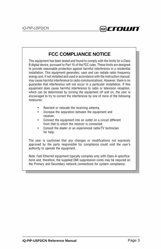
FCC COMPLIANCE NOTICEThis equipment has been tested and found to comply with the limits for a ClassB digital device, pursuant to Part 15 of the FCC rules. These limits are designedto provide reasonable protection against harmful interference in a residentialinstallation. This equipment generates, uses and can radiate radio frequencyenergy and, if not installed and used in accordance with the instruction manual,may cause harmful interference to radio communications. However, there is noguarantee that interference will not occur in a particular installation. If thisequipment does cause harmful interference to radio or television reception,which can be determined by turning the equipment off and on, the user isencouraged to try to correct the interference by one of more of the followingmeasures:
• Reorient or relocate the receiving antenna.• Increase the separation between the equipment and
receiver.• Connect the equipment into an outlet on a circuit different
from that to which the receiver is connected.• Consult the dealer or an experienced radio/TV technician
for help.
The user is cautioned that any changes or modifications not expresslyapproved by the party responsible for compliance could void the user’sauthority to operate the equipment.
Note: Fast-Ethernet equipment typically complies only with Class-A specifica-tions and, therefore, the supplied EMI suppression cores may be required onthe Primary and Secondary network connections for system compliance.

DECLARATION of CONFORMITY
European Representative’s Name and Address:
Peter Christensen, Nilesco Europe Willem Pyerstraat 21 1077 XK Amsterdam, Netherlands
Equipment Type: Control System Components
Family Name: IQ
Model Name: IQ-PIP-USP2/CN
EMC Standards: EN 55103-1:1995 Electromagnetic Compatibility – Product FamilyStandard for Audio, Video, Audio-Visual and Entertainment LightingControl Apparatus for Professional Use, Part 1: EmissionsEN 55103-1:1995 Magnetic Field Emissions-Annex A @ 10 cm and 1 MEN 61000-3-3:1995 Limitation of Voltage Fluctuations and Flicker inLow-Voltage Supply Systems Rated Current ≤16AEN 55022:1992 + A1:1995 & A2:1997 Limits and Methods of Measure-ment of Radio Disturbance Characteristics of ITE: Radiated, Class BLimits; Conducted, Class AEN 55103-2:1996 Electromagnetic Compatibility – Product FamilyStandard for Audio, Video, Audio-Visual and Entertainment LightingControl Apparatus for Professional Use, Part 2: ImmunityEN 61000-4-2:1995 Electrostatic Discharge Immunity (Environment E2-Criteria B, 4k V Contact, 8k V Air Discharge)EN 61000-4-3:1996 Radiated, Radio-Frequency, ElectromagneticImmu-nity (Environment E2, criteria A)EN 61000-4-4:1995 Electrical Fast Transient/Burst Immunity (Criteria B)EN 61000-4-5:1995 Surge Immunity (Criteria B)EN 61000-4-6:1996 Immunity to Conducted Disturbances Induced byRadio-Frequency Fields (Criteria A)EN 61000-4-11:1994 Voltage Dips, Short Interruptions and VoltageVariation
Safety Standard: EN 60065: 1998 Safety Requirements – Audio Video and SimilarElectronic Apparatus
I certify that the product identified above conforms to the requirements of the EMC CouncilDirective 89/336/EEC as amended by 92/31/EEC, and the Low Voltage Directive 73/23/EES asamended by 93/68/EEC.
Signed Date of Issue: March 15, 2001 Larry Coburn
Title Senior Vice President of Manufacturing
Crown Audio, Inc.1718 W. Mishawaka RoadElkhart, Indiana 46517 U.S.A.

IQ-PIP-USP2/CN
Page 5IQ-PIP-USP2/CN Reference Manual
Quick Install ProcedureThis procedure is provided for those who are already familiar with IQ System andCobraNetTM technologies, and who would like to install the IQ-PIP-USP2/CN in theshortest time possible. Less experienced installers or those wishing a fullexplanation of the installation procedure are encouraged to refer to Section 3 wherethe full installation procedure is described.
Prepare the IQ-PIP-USP2/CN:
1. Set the IQ address switch S1 (see Figures 2.1 and 3.1) on the IQ-PIP-USP2/CNto an unused IQ address. (Tip: Record the IQ address on the small field la-beled “IQ ADDRESS” that is provided on the PIP panel.)
Prepare the amplifier:
3. Turn down the level controls of the amplifier and turn off the amplifier.
4. Unplug the power cord of the amplifier from the AC mains.
5. Remove the existing PIP or cover panel from the amplifier back panel (twoscrews).
Install the IQ-PIP-USP2/CN into the amplifier:6. Carefully ground yourself to the chassis of the amplifier before installing the
IQ-PIP-USP2/CN. It is a good idea to maintain ground contact between your-self and the amplifier while inserting the module into the amplifier in the nextstep.
7. Turn the PIP upside down so you can clearly see the two ribbon cable con-nectors located on the underside of the board near the back corner (see Fig-ure 2.1). Attach the ribbon cables from your amp to the ribbon-cableconnectors. The 20-pin cable should be connected first, then the 18-pin cableshould be connected. Both ribbon cables should run untwisted from the am-plifier to the PIP module.
Important: Be careful when attaching the ribbon cable to the connector thatthe cable is properly seated before applying pressure to the connector. Forc-ing the cable onto the connector could cause the keying tabs, which ensureproper pin alignment, to break. Connecting the ribbon cables with improperpin alignments may result in damage to the PIP.
When both cables are firmly attached, turn the IQ-PIP-USP2/CN back to anupright position and insert into the PIP opening in the back of the amplifier.Take care while inserting the PIP to make sure you do not crimp, pinch orstretch the ribbon cables.
8. Tighten the two PIP mounting screws until it is secured to the amplifier backpanel, making sure the supplied star-washers penetrate the powder-coat fin-ish of the PIP panel for good ground connection.
Install the wiring:9. Connect the IQ-PIP-USP2/CN to the IQ System via the IQ Bus (see Section 3.4
if more information is needed).
10. Connect the IQ-PIP-USP2/CN to the CobraNet network hub or switch. Installthe supplied ferrite cores on the network cable, making two turns. (see Sec-tion 3.4 if more information is needed).
11. Reconnect the amplifier to the AC mains.
IQ-PIP-USP2/CN
Page 6 IQ-PIP-USP2/CN Reference Manual
CONTENTS
1Welcome81.1 Unpacking ..................................... 9
2 Controls, Connectors& Indicators ........................ 10
3 Installation ......................... 113.1 Prepare the PIP ............................ 11
3.2 Prepare the Amplifier ................... 12
3.3 Install the PIP into the Amplifier . 12
3.4 Install the Wiring ......................... 133.5 Adjust System Levels .................. 16
4 Hardware Features ................ 174.1 IQ Address Switch (S1) ............... 17
4.2 Reset/Preset Switch ..................... 174.3 Data Indicator ............................. 18
4.4 Preset Indicator ........................... 18
4.5 CobraNet Indicators ..................... 18
4.6 IQ Bus Input Connector ............... 184.7 IQ Bus Output Connector ............. 18
4.8 Primary Network Connector ......... 18
4.9 Secondary Network Connector .... 18
4.10 AUX Input/Output Connector ....... 194.11 IQ Bus Drop Out Relay ................ 19
5 Amplifier Controland Monitoring .................... 20
5.1 IOC Event Monitor ....................... 20
5.2 Input Signal Level Monitor ........... 205.3 Output Signal Level Monitor ........ 20
5.4 Thermal Headroom Level Monitor 20
5.5 Power/Standby Control ................ 21
5.6 Amp Information ......................... 215.7 Amp Mode ................................... 21
5.8 Amp Output Mode ....................... 21
5.9 Error Reporting ............................ 21
6 CobraNet ............................ 236.1 CobraNet Module Parameters ...... 23
6.2 CobraNet Input Routing ............... 24
6.3 CobraNet Output Routing ............ 24
7 Signal Processing ................. 267.1 Signal Processing Forms ............. 26
7.2 Signal Routing ............................. 26
7.3 Input Signal Attenuator ................ 267.4 Auto Standby ............................... 27
7.5 Input Signal Compressor/Limiter . 27
7.6 Programmable Filters .................. 27
7.7 Signal Delay ................................. 307.8 Peak Voltage Limiter .................... 30
7.9 Average Power Limiter ................. 31
7.10 Clip Eliminator ............................. 31
7.11 Thermal Limiter ........................... 317.12 Signal Mute ................................. 31
7.13 Output Trim Controls ................... 32
7.14 Polarity Inverter ........................... 32
7.15 Tie Switch .................................... 327.16 “Ghost Faders” ............................ 32
8 Load Supervision ................. 338.1 On/Off .......................................... 33
8.2 High Limit .................................... 338.3 Low Limit .................................... 33
8.4 Nominal Load Impedance ............ 33
8.5 Calculate ...................................... 33
8.6 Include in Standard Error Reporting . 338.7 Report to AUX ............................. 33
IQ-PIP-USP2/CN
Page 7IQ-PIP-USP2/CN Reference Manual
ILLUSTRATIONS1.1 IQ-PIP-USP2/CN Front Panel ......... 82.1 IQ-PIP-USP2/CN Controls,
Connectors and Indicators .......... 103.1 Address Switch (S1) ................... 113.2 Installing the IQ-PIP-USP2/CN .... 123.3 Standard IQ Bus Wiring “Loops” 133.4 RJ-45 Mating Plug ...................... 143.5 RJ-45 Output to Barrier Block Input . 143.6 RJ-45 Output to Din input. ......... 143.7 RJ-45 Input to Barrier
Block Output. ............................... 153.8 RJ-45 Input to Din Output. ......... 153.9 RJ-45 Output to RJ-45 Input. ..... 153.10Network Cable with Installed Core164.1 Indicators .................................... 189.1 Aux Input Modes ......................... 34
10.1 Basic Control Panels ................... 3810.2 General Control Tab .................... 3910.3 Presets Control Tab ..................... 40
10.4 Error Reporting Control Tab ........ 4110.5 Load Supervision Control Tab ..... 4210.6 Signal Path Control Tab .............. 4310.7 CobraNet Setup Control Tab ....... 4410.8 CobraNet Input Control Tab ........ 4510.9 CobraNet Output Control Tab ...... 4510.10 Star Network Topology .............. 4710.11 Multi-Star Topology ................... 4810.12 The Internal AUX Circuit ............ 5110.13 A Sample AUX Output Circuit .... 5210.14 Q-factor vs.Bandwidth ............... 5410.15 RJ-11 & RJ-45 Pin Assignments .... 5510.16 IQ Address Switch (S1) Settings
from 0 through 83 ...................... 5610.17 IQ Address Switch (S1) Settings
from 84 through 167 .................. 5710.18 IQ Address Switch (S1) Settings
from 168 through 250 ................ 5810.19 IQ-PIP-USP2/CN Signal Flow
Block Diagram ............................. 59
8.8 Test Indicator ............................... 33
8.9 Low/Normal/High Indicator ......... 33
8.10 Z Avg Monitor .............................. 33
9 Utilities ............................. 349.1 User Presets ................................ 34
9.2 Memory Backup .......................... 34
9.3 AUX Output .................................. 349.4 AUX Input .................................... 34
10 Working With IQ ................... 3610.1 A Closer Look at IQ ...................... 36
10.2 IQ-PIP-USP2/CN User Interface ... 38
10.3 IQ Bus Wiring .............................. 4610.4 A Closer Look at CobraNet ........... 47
10.5 Using the AUX Connector ............ 5010.6 Load Supervision Applications .... 52
10.7 Q-Factor Calculation .................... 54
10.8 Working with RJ-11 and RJ-45Connectors .................................. 55
10.9 IQ Address Tables ........................ 55
10.10 Signal Flow Block Diagram ......... 59
11 Specifications ..................... 6011.1 General ........................................ 6011.2 IQ Bus Data Communication ........ 60
11.3 Audio ........................................... 61
11.4 IQ System Data Acquisition ......... 61
12 Factory Service .................... 62

IQ-PIP-USP2/CN
Page 8 IQ-PIP-USP2/CN Reference Manual
1 WelcomeThe IQ-PIP-USP2/CN is a PIP™ (Pro-grammable Input Processor) inputmodule for Crown® PIP2™-compat-ible amplifiers.* It connects the am-plifier to the IQ Bus of an IQ Sys-tem®, allowing the amplifier to becontrolled and monitored via IQ, andfeatures CobraNet™ connectivity fordigital audio networking.
The IQ-PIP-USP2/CN is an IQ2™-series component. This means it sup-ports IQ UCODE protocol and re-quires an IQ System with an IQ2-compatible IQ interface. UCODE(universal code) enables users andthird parties to develop custom soft-ware objects to control and monitorIQ2-compatible components like theIQ-PIP-USP2/CN.
The IQ-PIP-USP2/CN utilizes the lat-est advancements in DSP technol-ogy to provide state-of-the-art fea-tures and performance. Similar tothe the IQ-PIP-USP2, it offers a vari-ety of programmable functions in-
Figure 1.1 IQ-PIP-USP2/CN Front Panel
cluding crossovers, equalizers, sig-nal delay, input compressors, multi-mode (peak, average, clip) outputlimiters and load supervision. Thefamiliar IQ-AUX port has been en-hanced and the “Listen-Bus” fea-ture is now available via CobraNet.
A full 24-bit signal path is main-tained by using state-of-the-art 24-bit Digital-to-Analog Converters,along with the audio-industry stan-dard Motorola 56000 series 24/48-bit DSP.
The IQ-PIP-USP2/CN is powered bythe amplifier, and all unit param-eters are stored in non-volatile Flashmemory for reliable system back-up. Ten presets are available forquick and easy unit configurationchanges. Each IQ-PIP-USP2/CN in-cludes an IQ address switch allow-ing the unit to have a unique ad-dress on the IQ Bus.
This manual will help you success-fully install your unit. We stronglyrecommend you read all the instruc-tions, warnings and cautions con-tained within. Also, for your protec-tion, please send in the warrantyregistration card today and savethe bill of sale since it is your officialproof of purchase.
* You must have a PIP2-compatibleamplifier to use the IQ-PIP-USP2/CN.To determine if your amplifier isPIP2-compatible, look for the logo on the back of the amplifier. TheIQ-PIP-USP2/CN is NOT compatiblewith older Crown PIP amplifiers.

IQ-PIP-USP2/CN
Page 9IQ-PIP-USP2/CN Reference Manual
1.1 UnpackingThe unit is shipped in a protectiveantistatic bag.
CAUTION: STATIC ELECTRICITYMAY DAMAGE THE UNIT. Use cau-tion when handling the unit. Care-fully ground yourself BEFORE touch-ing the unit. Avoid unnecessarilytouching the components or solderpads on the circuit boards.
Please unpack and inspect the unitfor any damage that may have oc-
curred during transit. If damage isfound, notify the transportation com-pany immediately. Only you, theconsignee, may initiate a claim withthe carrier for shipping damage.Crown will be happy to cooperatefully as needed. Save the shippingcarton as evidence of damage forthe shipper’s inspection.
Even if the unit arrived in perfectcondition, as most do, save all pack-ing materials. NEVER SHIP THEUNIT WITHOUT THE FACTORYPACK.
IQ-PIP-USP2/CN
Page 10 IQ-PIP-USP2/CN Reference Manual
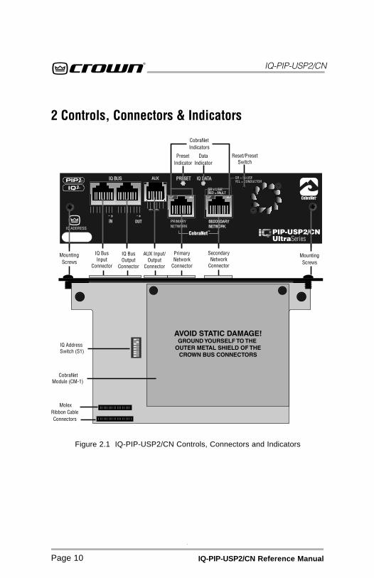
Figure 2.1 IQ-PIP-USP2/CN Controls, Connectors and Indicators
2 Controls, Connectors & Indicators
IQ-PIP-USP2/CN
Page 11IQ-PIP-USP2/CN Reference Manual
3 InstallationBefore beginning, please carefullynote:
CAUTION: STATIC ELECTRICITYMAY DAMAGE THE IQ-PIP-USP2/CNMODULE. Use caution when han-dling the unit. Carefully ground your-self BEFORE touching the IQ-PIP-USP2/CN module. Avoid unneces-sarily touching the components orsolder pads on the circuit boards.
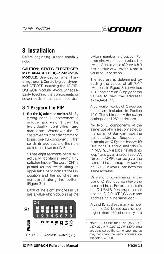
3.1 Prepare the PIP1. Set the IQ address switch S1..... By
giving each IQ component aunique address, it can beindividually controlled andmonitored. Whenever the IQSystem wants to send a commandto just one IQ component, it firstsends its address and then thecommand down the IQ Bus.
S1 has eight segments because itactually contains eight tinyswitches inside. The word “ON” isprinted on the switch along itsupper left side to indicate the ONposition and the switches arenumbered along the bottom(Figure 3.1).
Each of the eight switches in S1has a value which doubles as the
switch number increases. Forexample switch 1 has a value of 1;switch 2 has a value of 2; switch 3has a value of 4; switch 4 has avalue of 8 and so on.
The address is determined byadding the values of all “ON”switches. In Figure 3.1, switches1, 3, 4 and 7 are on. Simply add thevalues to find the address:1+4+8+64=77.
A convenient series of IQ addresstables are included in Section10.9. The tables show the switchsettings for all 250 addresses.
No two IQ components of thesame type which are connected tothe same IQ Bus can have thesame address.* Suppose, forexample, an IQ System has two IQBus loops, 1 and 2, and this IQ-PIP-USP2/CN is to be installed intoloop 1 and given an address of 77.No other IQ PIPs can be given thesame address in loop 1. However,an IQ PIP in loop 2 can have thesame address.
Different IQ components in thesame IQ Bus loop can have thesame address. For example, bothan IQ–USM 810 mixer/processorand an IQ-PIP-USP2/CN can useaddress 77 in the same loop.
A valid IQ address is any numberfrom 1 to 250. Do not use a numberhigher than 250 since they are
Figure 3.1 Address Switch (S1)
* Note: All IQ PIP modules (IQ-P.I.P.-DSP, IQ-P.I.P.-SMT, IQ-PIP-USP2, etc.)are considered the same type, and somay not share the same address onthe same IQ Bus.

IQ-PIP-USP2/CN
Page 12 IQ-PIP-USP2/CN Reference Manual
Figure 3.2 Installing theIQ-PIP-USP2/CN
3.2 Prepare the Amplifier3. Turn down the level controls (full
counterclockwise) and turn offthe amplifier.
4. Disconnect the amplifier’spower cord.
5. Remove the existing PIP fromthe amplifier back panel (twoscrews). This may involvedisconnecting the PIP from a PIP2input adapter. If a PIP2 inputadapter is already present,remove the ribbon cables from theadapter.
3.3 Install the PIP intothe Amplifier6. Carefully ground yourself to the
chassis of the amplifier beforeinstalling the IQ-PIP-USP2/CN. It isa good idea to maintain groundcontact between yourself and theamplifier while inserting themodule into the amplifier.
7. Install the IQ-PIP-USP2/CN intothe amplifier: Turn the IQ-PIP-USP2/CN over so that you canclearly see the two ribbon-cableconnectors located on theunderside of the circuit board (seeFigure 3.2). Connect the two inputribbon cables of the amplifier. The20-pin cable (A) should beconnected first, then the 18-pincable (B) should be connected.
reserved for special use. Anaddress of “0” (zero) places theunit in “stand alone” mode. Thisspecial mode disables the IQ busport, preventing communicationwith the IQ System.
IQ-PIP-USP2/CN
Page 13IQ-PIP-USP2/CN Reference Manual
Both ribbon cables should runsmoothly from the amplifier to thePIP card (see Figure 3.2).
Important: Be careful whenattaching the ribbon cable to theconnector that the cable isproperly seated before applyingpressure to the connector.
Forcing the cable onto theconnector could cause the keyingtabs, which ensure proper pinalignment, to break. Connectingthe ribbon cables with improperpin alignments may result indamage to the PIP.
When both cables are firmlyattached, turn the IQ-PIP-USP2/CN back to an upright position andinsert into the PIP opening in theback of the amplifier. Take carewhile inserting the PIP to makesure you do not crimp, pinch orstretch the ribbon cables.
8. Tighten the two PIP mountingscrews until the PIP is secured tothe amplifier back panel. Be sureto use the supplied star-washers for good groundconnection.
3.4 Install the Wiring9. Connect the IQ-PIP-USP2/CN to
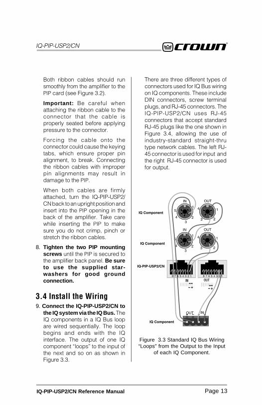
the IQ system via the IQ Bus. TheIQ components in a IQ Bus loopare wired sequentially. The loopbegins and ends with the IQinterface. The output of one IQcomponent “loops” to the input ofthe next and so on as shown inFigure 3.3.
There are three different types ofconnectors used for IQ Bus wiringon IQ components. These includeDIN connectors, screw terminalplugs, and RJ-45 connectors. TheIQ-PIP-USP2/CN uses RJ-45connectors that accept standardRJ-45 plugs like the one shown inFigure 3.4, allowing the use ofindustry-standard straight-thrutype network cables. The left RJ-45 connector is used for input andthe right RJ-45 connector is usedfor output.
Figure 3.3 Standard IQ Bus Wiring“Loops” from the Output to the Input
of each IQ Component.
IQ-PIP-USP2/CN
Page 14 IQ-PIP-USP2/CN Reference Manual
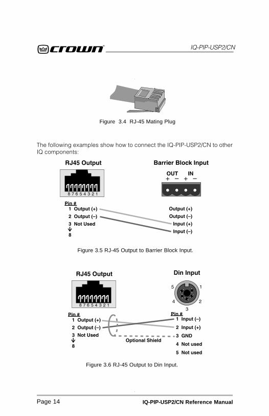
Figure 3.6 RJ-45 Output to Din Input.
Figure 3.5 RJ-45 Output to Barrier Block Input.
The following examples show how to connect the IQ-PIP-USP2/CN to otherIQ components:
Figure 3.4 RJ-45 Mating Plug
IQ-PIP-USP2/CN
Page 15IQ-PIP-USP2/CN Reference Manual
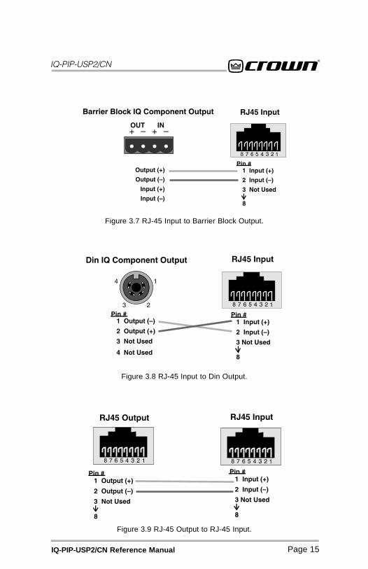
Figure 3.7 RJ-45 Input to Barrier Block Output.
Figure 3.8 RJ-45 Input to Din Output.
Figure 3.9 RJ-45 Output to RJ-45 Input.
IQ-PIP-USP2/CN
Page 16 IQ-PIP-USP2/CN Reference Manual
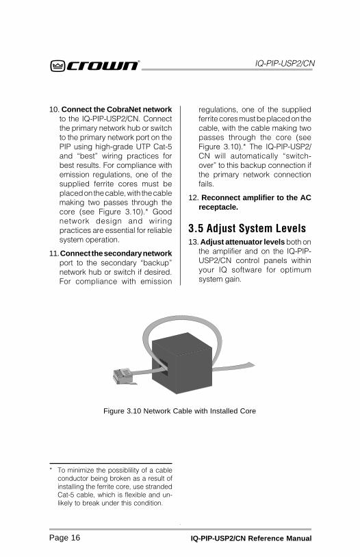
10. Connect the CobraNet networkto the IQ-PIP-USP2/CN. Connectthe primary network hub or switchto the primary network port on thePIP using high-grade UTP Cat-5and “best” wiring practices forbest results. For compliance withemission regulations, one of thesupplied ferrite cores must beplaced on the cable, with the cablemaking two passes through thecore (see Figure 3.10).* Goodnetwork design and wiringpractices are essential for reliablesystem operation.
11. Connect the secondary networkport to the secondary “backup”network hub or switch if desired.For compliance with emission
regulations, one of the suppliedferrite cores must be placed on thecable, with the cable making twopasses through the core (seeFigure 3.10).* The IQ-PIP-USP2/CN will automatically “switch-over” to this backup connection ifthe primary network connectionfails.
12. Reconnect amplifier to the ACreceptacle.
3.5 Adjust System Levels13. Adjust attenuator levels both on
the amplifier and on the IQ-PIP-USP2/CN control panels withinyour IQ software for optimumsystem gain.
Figure 3.10 Network Cable with Installed Core
* To minimize the possiblility of a cableconductor being broken as a result ofinstalling the ferrite core, use strandedCat-5 cable, which is flexible and un-likely to break under this condition.
IQ-PIP-USP2/CN
Page 17IQ-PIP-USP2/CN Reference Manual
4 Hardware FeaturesThis section describes the IQ-PIP-USP2/CN hardware features. Thesefeatures are accessed via controlslocated on the unit itself.
4.1 IQ Address Switch (S1)An 8-section DIP switch is used toset the IQ address of the unit. A validIQ address is any number from 1 to250. Numbers higher than 250 arereserved for special use. An ad-dress of “0” places the unit in stand-alone mode. In this mode, the IQbus port is disabled and the PIP willnot function with IQ software.
This switch is located on the under-side of the circuit board. Each IQcomponent on a IQ Bus is given aunique IQ address so it can be inde-pendently controlled and monitored.Two or more IQ components of thesame type should NEVER have thesame address on the same IQ Busloop.
For information on setting the IQAddress Switch, see Section 3.1.
4.2 Reset/Preset SwitchA recessed reset/preset switch, ac-cessible from outside the PIP panel,performs two functions. First, it en-ables the IQ-PIP-USP2/CN to berestored to factory default settings,and second, allows the user to re-call any of ten presets.* A straight-ened paper clip or similar small ob-ject is required to press the resetswitch.
To select one of the ten presets,complete the following steps:
Remove all input signals. With thepower on, briefly press the switchfor less than two seconds to togglethrough the 10 user-defined presetsstored in firmware. Each press willincrement the selected preset byone. After the switch is released, theDATA light will flash rapidly for amoment, then the PRESET indicatorwill blink to indicate the preset num-ber selected. Restore input signals.
To restore the unit to the factorydefault settings, complete the fol-lowing steps:
Remove all input signals. With thepower on, press the switch and holdfor more than 2 seconds, or until theDATA indicator blinks twice, and allsettings will be reset to factory de-fault. When the switch is released,the DATA indicator will flash rapidlyfor a moment. Restore input signals.
To clear all memory and set tofactory default presets:
Remove all input signals. Press inand hold the switch while applyingpower to the unit. The settings willbe reset to factory default. Impor-tant: This action will re-write theflash memory and erase storedpresets. With the button held in andpower applied, the DATA and PRE-SET indicators will both be lit. Whenthe button is released, then the DATAindicator will flash rapidly for a mo-ment. After the unit has been reset tothe factory default settings, it willbehave like a standard PIP until it isreprogrammed by an IQ System. Re-store input signals.* Max Preset and Min Preset objects dic-
tate the range of Presets that can beselected by the Reset/Preset Switch.
IQ-PIP-USP2/CN
Page 18 IQ-PIP-USP2/CN Reference Manual
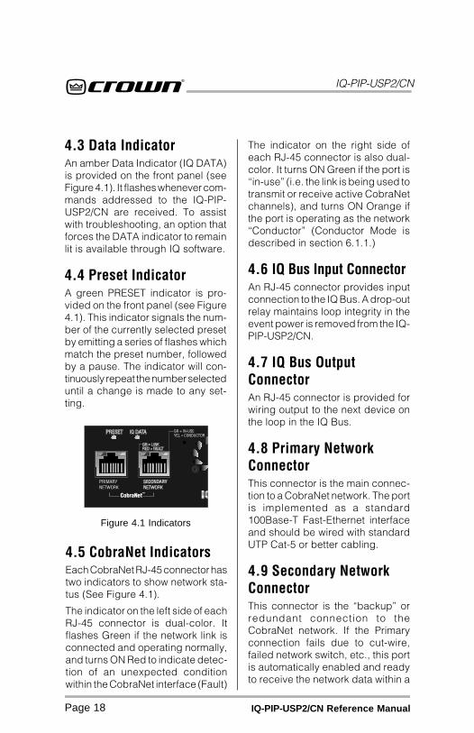
The indicator on the right side ofeach RJ-45 connector is also dual-color. It turns ON Green if the port is“in-use” (i.e. the link is being used totransmit or receive active CobraNetchannels), and turns ON Orange ifthe port is operating as the network“Conductor” (Conductor Mode isdescribed in section 6.1.1.)
4.6 IQ Bus Input ConnectorAn RJ-45 connector provides inputconnection to the IQ Bus. A drop-outrelay maintains loop integrity in theevent power is removed from the IQ-PIP-USP2/CN.
4.7 IQ Bus OutputConnectorAn RJ-45 connector is provided forwiring output to the next device onthe loop in the IQ Bus.
4.8 Primary NetworkConnectorThis connector is the main connec-tion to a CobraNet network. The portis implemented as a standard100Base-T Fast-Ethernet interfaceand should be wired with standardUTP Cat-5 or better cabling.
4.9 Secondary NetworkConnectorThis connector is the “backup” orredundant connection to theCobraNet network. If the Primaryconnection fails due to cut-wire,failed network switch, etc., this portis automatically enabled and readyto receive the network data within a
4.3 Data IndicatorAn amber Data Indicator (IQ DATA)is provided on the front panel (seeFigure 4.1). It flashes whenever com-mands addressed to the IQ-PIP-USP2/CN are received. To assistwith troubleshooting, an option thatforces the DATA indicator to remainlit is available through IQ software.
4.4 Preset IndicatorA green PRESET indicator is pro-vided on the front panel (see Figure4.1). This indicator signals the num-ber of the currently selected presetby emitting a series of flashes whichmatch the preset number, followedby a pause. The indicator will con-tinuously repeat the number selecteduntil a change is made to any set-ting.
4.5 CobraNet IndicatorsEach CobraNet RJ-45 connector hastwo indicators to show network sta-tus (See Figure 4.1).
The indicator on the left side of eachRJ-45 connector is dual-color. Itflashes Green if the network link isconnected and operating normally,and turns ON Red to indicate detec-tion of an unexpected conditionwithin the CobraNet interface (Fault)
Figure 4.1 Indicators
IQ-PIP-USP2/CN
Page 19IQ-PIP-USP2/CN Reference Manual
few seconds. The port is imple-mented as a standard 100Base-TFast-Ethernet interface and shouldbe wired with standard UTP Cat-5 orbetter cabling.
4.10 AUX Input/OutputConnectorAn RJ-11 connector provides bothAuxiliary input and output connec-tion to outside circuits. Operation of
the AUX Output is described in Sec-tion 9.3, and AUX Input operation isdescribed in Secton 9.4.
4.11 IQ Bus Drop Out Relay A “Drop out” relay is provided onthe IQ Bus ports to maintain thecontinuity of the IQ communicationloop even if the IQ-PIP-USP2/CNloses power.
IQ-PIP-USP2/CN
Page 20 IQ-PIP-USP2/CN Reference Manual
* This is assumed to be 70V or the rated8-ohm output for Com-Tech amplifiersor the rated 8-ohm output voltage for allother amplifiers.
** Thermal Headroom on your Crown am-plifier may be labeled Output DeviceEmulation Protection (ODEP®).
***See the amplifier’s Reference orOwner’s Manual for more informationabout ODEP and how it works.
5 Amplifier Control andMonitoringThis section describes theIQ-PIP-USP2/CN amplifier controland monitoring features. These fea-tures are accessed via IQ for Win-dows software. Please refer to theIQ for Windows documentation ifyou are unfamiliar with IQ software.
5.1 IOC Event MonitorThe Input/Output Comparator(IOC®) of each channel of the ampli-fier can be monitored by the IQSystem. The IOC circuitry acts as asensitive distortion meter to provideyou proof of distortion-free perfor-mance. If distortion of any kindequals or exceeds 0.05%, the IOCcircuit will cause an IOC Event Moni-tor on the front of the amplifier toflash. The IQ-PIP-USP2/CN cancause a warning to flash on yourcomputer screen via IQ for Win-dows software indicating an IOCevent, Also, it can report IOC eventsto its AUX port.
5.2 Input Signal LevelMonitorThe input signal level of each chan-nel can be monitored. This monitorfeature has a range from +20 dBu to–40 dBu in ½-dB steps.
5.3 Output Signal LevelMonitorThe output signal level of each chan-nel of the amplifier can be moni-tored. This monitor feature has arange from 0 dB to –40 dB where
0 dB is referenced to the rated out-put voltage of the amplifier model.*
The IQ-PIP-USP2/CN featuresscaled output level meters. By fac-tory default, the meters are cali-brated such that 0 dB equals theamplifier’s rated output into 4 or 8ohms. If the IQ-PIP-USP2/CN is in-stalled into a Com-Tech® amplifier,the meters default to 0 dB equals 70Vrms. Changing the 4/8 - 70V modesoftware switch selects the respec-tive scaling.
5.4 Thermal HeadroomLevel MonitorThe Thermal Headroom level** ofeach channel of the amplifier can bemonitored by the IQ software. Thislevel represents the percent of avail-able power/thermal capacity that iscurrently being used within the out-put section of the amplifier. Whenthe thermal headroom level reaches100%, the amplifier cannot produceany more power and it will begin tolimit the drive level to the outputdevices to protect them from toomuch stress*** The Thermal Limiterfeature of the IQ-PIP-USP2/CN canbe set to engage upon a pre-se-lected thermal level. (See Section5.9.)
IQ-PIP-USP2/CN
Page 21IQ-PIP-USP2/CN Reference Manual
5.5 Power/StandbyControlEach channel’s high-voltage supplycan be independently turned on andoff.
5.6 Amp InformationSeveral useful items of informationabout the host amplifier are deter-mined by the IQ-PIP-USP2/CN atstart-up. These include manufac-turer, model, date code, serial num-ber, and revision level. These canbe printed from the system inven-tory (no on-screen display is avail-able).
5.7 Amp ModeThe Stereo (Dual), Bridge-Mono orParallel-Mono mode of the amplifiercan be stored in the IQ-PIP-USP2/CN’s memory so the IQ System isaware of the position of the amplifier’soutput mode switch. Storing this set-ting serves as an “electronic re-minder” to the system; however, theactual mode of the amplifier cannotbe controlled with this setting. Thesoftware amp mode setting can bedisplayed or modified via IQ for Win-dows software.
5.8 Amp Output ModeOn Com-Tech series amplifiers, theoutput mode (4/8 ohm or 70V) of theamplifier can be stored in the IQ-PIP-USP2/CN’s memory so the IQSystem is aware of the amplifier’soutput mode setting. This softwareswitch also scales the output levelmeters for calibrated output indica-tion.
5.9 Error ReportingFour different error conditions canbe detected by the IQ-PIP-USP2/CN.They include IOC, Thermal, Fault,and Load. Reporting for each condi-tion can be individually configuredfor output to the AUX port, the IQ forWindows software, or both. If youchoose system software notification,you will receive notice of the faultcondition via the IQ System. If youchoose AUX out notification, the AUXout signal will switch from ON to OFFwhen a selected error has occurred.If you prefer, reporting can beswitched off completely. Followingis a description of each error condi-tion:
IOC: You can choose to be informedwhen an excessive number of IOCevents occur over a unit of time ineither channel of the amplifier. WhenIOC error reporting is on, an alert willbe generated when the number ofIOC events per unit of time specifiedexceeds a count that you set. TheCount control lets you set a numberof IOC events per unit of time allowedbefore an error is generated. Therange is 1 to 100. The Time controllets you set the unit of time in sec-onds during which the number ofIOC error events are counted forpossible error reporting. The rangeis 1 to 10 seconds.
Thermal: You can choose to bewarned if the thermal level rises abovea predetermined level. The Thresh-old control lets you set the thermallevel above which an error messagewill be reported. The range is from 1to 100%.
Fault: You can choose to be warned

IQ-PIP-USP2/CN
Page 22 IQ-PIP-USP2/CN Reference Manual
when an amplifier “fault” conditionoccurs when a channel fails. PIP2-compatible devices monitor a “fault”signal from the amplifier.
Load: You can choose to be warned
if the impedance of the load beingdriven by the amplifier falls out of apre-selected range. See Section 8for instructions on setting up theload supervision feature.
IQ-PIP-USP2/CN
Page 23IQ-PIP-USP2/CN Reference Manual
6 CobraNetCobraNet is a licensed technologydeveloped by Peak Audio, Inc. con-sisting of proprietary communica-tions protocol, firmware and hard-ware. It allows reliable, deterministictransmission of digital audio over a100Base-T Fast-Ethernet network.The IQ-PIP-USP2/CN operates as anetworked device on a CobraNetnetwork, and interfaces digital audiofrom the network to the amplifer.Refer to Section 10.4 for a morethorough discussion about CobraNettechnology.*
This section describes theIQ-PIP-USP2/CN’s CobraNet con-trol and monitoring features. Thesefeatures are accessed via IQ forWindows software. Please refer tothe IQ for Windows documentation ifyou are unfamiliar with IQ software.
6.1 CobraNet ModuleParametersThe internal CobraNet Network In-terface Module contains several pa-rameters for control and monitor ofstatus of the CobraNet network, anddo not directly affect the IQ network.These variables can also be con-
* For the most comprehensive informa-tion available on CobraNet technology,visit Peak Audio’s CobraNet website atwww.peakaudio.com/CobraNet/.
** CobraCAD is a software tool that pro-vides a simple graphic user interfacefor the design, configuration and moni-toring of CobraNet networks. It is avail-able for download from Peak Audio’swebsite at www.peakaudio.com/CobraNet/.
trolled and monitored through theCobraNet network usingCobraCAD™** or other industry-standard SNMP-enabled networkmanagement software.
6.1.1. ConductorAny CobraNet device can be con-figured to operate either as NetworkConductor or a Performer:
• Active Indicator: This indicator,viewable in IQ for Windowssoftware, reports the presentConductor status of the device.If the indicator is ON, the unit isoperating as the networkConductor. When OFF, the unit isoperating as a Performer.
• Priority: This parameter adjuststhe priority level for becomingthe Conductor. When set tozero, the IQ-PIP-USP2/CN willnever function as the Conductor,and when set to 255 it will alwaysfunction as the Conductor. Thehigher the priority number, themore likely unit will act as theConductor. The Priority object isstored in presets.
6.1.2 System Name This parameter is user-settable toany alpha-numeric string of 30 char-acters or less. The intended use isto communicate a unique name forthe particular device to a network.The System Name object is storedin presets.
6.1.3 System DescriptionThis parameter is configured at thefactory and is read-only. The in-tended use is to communicate aunique device description to a net-work.

IQ-PIP-USP2/CN
Page 24 IQ-PIP-USP2/CN Reference Manual
6.1.4 System LocationThis parameter is user-settable toany alpha-numeric string of 30 char-acters or less. The intended use is tocommunicate a unique descriptionof the device location to a network.This object is stored in presets.
6.1.5 System ContactThis parameter is user-settable toany alpha-numeric string of 30 char-acters or less. The intended use is tocommunicate the designated con-tact person (in case of service orother network issue) to the network.This object is stored in presets.
6.1.6 Firmware VersionThis parameter is configured at thefactory and is read-only. The in-tended use is to communicate thepresently loaded CobraNet modulefirmware version to a network.
6.1.7 MAC AddressThis parameter is configured at thefactory and is read-only. The settingdefines a unique IEEE802-recog-nized address for use with anyEthernet based network.
6.1.8 IP AddressThis parameter is user-configuredfor IP based networks. The intendeduse is to uniquely identify the devicewith respect to the available IP ad-dress space. The IP address mustbe configured in order to control/monitor the device with IP basedsoftware.
6.2 CobraNet InputRoutingCobraNet input routing includes thefollowing controls:
6.2.1 CobraNet ReceiveBundlesThe IQ-PIP-USP2/CN can receivefour unique CobraNet Bundles (RxA,RxB, RxC, RxD). Each Bundle in-cludes an “Active” indicator to indi-cate whether the particular Bundleis being actively transmitted ontothe network.
6.2.2 CobraNet ReceiveChannelsEach CobraNet Bundle contains upto eight digital audio channels. Eachchannel is selected at its respectivetransmitter to contain none, 16-, 20-or 24-bit audio sample data. A totalof two audio channels can be pro-cessed by the IQ-PIP-USP2/CN atany one time. Any of the eight chan-nels on a bundle can be can berouted to either of the two process-ing channel inputs on the IQ-PIP-USP2/CN.
• Channel Label: Each receiveddigital audio channel can beassigned a user-specified labelto indicate intended use, sourceor other information. The label isstored in presets along with thebundle number and receivechannel information.
6.3 CobraNet OutputRoutingCobraNet output routing includesthe following controls:
6.3.1 CobraNet TransmitBundlesThe IQ-PIP-USP2/CN can transmitup to four unique CobraNet Bundles(TxA, TxB, TxC, TxD). Each Trans-
IQ-PIP-USP2/CN
Page 25IQ-PIP-USP2/CN Reference Manual
mit Bundle includes the followingcontrols and monitor functions:
• Receiver Count: This meterreports the number of CobraNetnodes actively receiving theBundle being sourced to thenetwork by this bundle.
• Transmit Position: This meterreports the transmitter’s relativeposition as assigned by theCobraNet Conductor. Lowernumbers are transmitted beforehigher numbers.
• Transmit Priority: This controladjusts the relative priority for theparticular transmitter. Highernumbers indicate a higherpriority. One may choose toincrease the transmitter priorityfor an emergency pagemicrophone in a heavily loadednetwork. The Transmit Priorityobject is stored in presets.
6.3.2. CobraNet TransmitChannelsEach CobraNet Bundle can containup to eight unique digital audio chan-nels. Each channel is selected at its
respective transmitter to containnone, 16-, 20- or 24-bit audio sampledata. A total of 32 channels can betransmitted by a single IQ-PIP-USP2/CN at any one time; however, onlytwo channels available to sourcefrom. The CobraNet Transmit Chan-nel object is stored in presets.
••••• Channel Label: Each transmitteddigital audio channel can beassigned a user-specified labelto indicate intended use, sourceor other information. TheChannel Label object is stored inpresets.
It is important to note that the signalbeing placed on the CobraNet net-work comes from the actual outputof the amplifier. The signal is scaleddown and converted to a digital sig-nal, and as such, it is a true repre-sentation of the output of the ampli-fier. Having this signal available onthe Cobranet network extends the“Listen Bus” feature found on otherIQ-PIP modules to any network user,allowing them to listen to the outputof any networked amplifier from anylocation on the network.
IQ-PIP-USP2/CN
Page 26 IQ-PIP-USP2/CN Reference Manual
7 Signal ProcessingThis section describes theIQ-PIP-USP2/CN DSP signal pro-cessing features. These featuresare accessed via IQ for Windowssoftware. Please refer to the IQ forWindows documentation if you areunfamiliar with IQ software.
7.1 Signal ProcessingFormsMany of the advanced features ofthe IQ-PIP-USP2/CN are accessedfrom the IQ for Windows softwareSignal Path panel.* This special fea-ture allows the audio signal to beprocessed and routed according tothree available “form” specifications:2x2 Dual Processor, 1x2 Cross-over/Processor + EQ, and AMCb+.
When a new form type is selected,the required signal processingblocks are automatically arrangedto fit the scheme of the selectedform. The result is a preset “tem-plate” for signal processing thatmakes it faster and easier for you totailor your system to your specificneeds.
7.1.1 2x2 Dual Processor2x2 Dual Processor is the defaultform configuration, and provides truestereo signal processing, with allsignal processing options availableon both channels.
* For more information about the struc-ture of the forms environment within IQfor Windows, consult the documenta-tion and help files which accompanythe software.
* For more information about thePIP-AMCb, consult the PIP-AMCb Ref-erence Manual, or contact CrownTechnical Support.
7.1.2 1x2 Crossover/Processor + EQThe 1x2 Crossover/Processor + EQform provides Auto Standby, InputCompression Limiter, Crossover,and DSP Filter Processing optionson the signal for Channel 1 only, Thesignal is then routed to the Channel1 and Channel 2 signal processingblocks for further processing androuting to the amplifier.
7.1.3 AMCb+The AMCb+ form mimics the func-tion of Crown’s PIP-AMCb.* The sig-nal is routed only to Channel 1 forDSP crossover, then the signal isrouted to the Channel 1 and Chan-nel 2 signal processing blocks forfurther processing and routing tothe amplifier. In the AMCb form,Box EQ is specified for Channel 1,and CD Horn EQ is specified forChannel 2.
7.2 Signal RoutingUsing IQ for Windows software, youcan choose either or both Channel 1and Channel 2 inputs to drive theprocessing path for each channel ofthe IQ-PIP-USP2/CN. You can alsoroute the output of either processingchannel to Channel 1 or Channel 2amplifier inputs.
7.3 Input SignalAttenuatorAn attenuator at the input of eachchannel is used to control the input
IQ-PIP-USP2/CN
Page 27IQ-PIP-USP2/CN Reference Manual
* 1:1 is the same as “off.”
signal level. Each attenuator has arange from 0 dB to –80 dB in ½ dBsteps. (Zero equals no attenuation.)
7.4 Auto StandbyThe Auto Standby feature automati-cally turns off the high-voltage sup-plies of the amplifier output when noaudio signal is detected at the inputfor a predetermined period of time.The channels are controlled inde-pendently. Four parameters controlthis feature:
On/Off: Turns this function on/off.
Input Gate Level: Sets the level, indB, below which the high voltagesupply of an amplifier channel willbe turned off. The range is from +16dBu to –40 dBu.
Turn-Off Delay: Sets the time, inminutes, that the input signal mustremain below the Standby Level be-fore the channel’s high-voltage sup-ply is turned off. The range is from 0to 255 minutes. A setting of 0 (zero)yields a turn-off delay of approxi-mately 2 seconds to facilitate setupof the function.
Power-On Delay: Enables or dis-ables the IQ address turn-on delay.This delay prevents all the amplifi-ers from turning on at the sameinstant and tripping power break-ers. The turn-on delay is calculatedby: 10 msec x IQ address value. Itmay be desirable to disable thisfeature so that the first syllable ofspeech is not missed in a voicepage application.
7.5 Input SignalCompressor/LimiterAn input signal compressor/limiteris available for each channel. Fiveparameters control this feature:
On/Off: Turns this function on or off.
Threshold: Sets the threshold, indB, above which the compressoracts. The level is measured at theinput to the PIP and corresponds tothe level shown on an input meter.The compressor is “feed-forward,”meaning that the level detection pointis located before the gain controlstage. The range is from +16 dBu to–40 dBu.
Attack Time: Sets the attack time ofthe compressor. The attack time isdefined as the time it takes the com-pressor to attenuate the input signalby 10 dB. The range is from 1 milli-second to 2 seconds.
Release Time: Sets the release timeof the compressor. The release timeis defined as the time it takes thecompressor to increase the inputgain by 10 dB. The range is 100milliseconds to 30 seconds.
Compressor Ratio: Sets the com-pression ratio for the compressor.The range is 1, 2, 4, 8, 16, 32, ∞ to 1.*
7.6 Programmable FiltersEach channel can have as many aseight different cascaded filters (the
IQ-PIP-USP2/CN
Page 28 IQ-PIP-USP2/CN Reference Manual
* “Biquad” refers to the double quadraticequations which mathematically de-scribe each filter implemented in thedigital signal processor.
actual number depends on the mixof filters chosen). There are sevendifferent filter types from which tochoose.
Low-Pass Crossover Filter (1st–4th order)
High-Pass Crossover Filter (1st–4th order)
Parametric Equalization Filter (2ndorder only)
Low-Pass Equalization Filter (2ndorder only)
High-Pass Equalization Filter (2ndorder only)
Low-Pass Shelving Equalization(1st order only)
High-Pass Shelving Equalization(1st order only)
DSP filters can be processed pre orpost crossover, depending uponwhich form the IQ-PIP-USP2/CN isconfigured in (see the IQ for Win-dows documentation for more infor-mation about forms).
All filters have IIR based topologiesto insure a proper magnitude/phaserelationship for use in professionalaudio applications such as equal-izer or crossover (dividing) networks.Each channel has a total of eight“biquad” filter cells.*
All filters with adjustable Q-factorscan be set in fractions of an octave.See Section 10.7 for informationabout calculating Q-factors.
An indicator in the software showshow much DSP resources are beingused by the selected filters. One3rd- or 4th-order filter uses theequivalent of two 1st- or 2nd-orderfilters.
1st-, 2nd-, 3rd- and 4th-order re-sponses result in 6-, 12-, 18- and 24-dB/octave roll-offs, respectively.
A description and list of the param-eters of each filter type are pre-sented next:
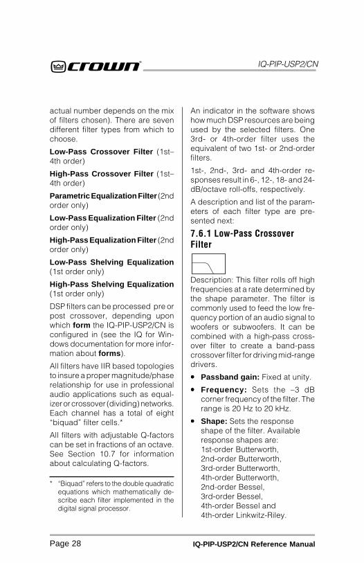
7.6.1 Low-Pass CrossoverFilter
Description: This filter rolls off highfrequencies at a rate determined bythe shape parameter. The filter iscommonly used to feed the low fre-quency portion of an audio signal towoofers or subwoofers. It can becombined with a high-pass cross-over filter to create a band-passcrossover filter for driving mid-rangedrivers.
••••• Passband gain: Fixed at unity.
••••• Frequency: Sets the –3 dBcorner frequency of the filter. Therange is 20 Hz to 20 kHz.
••••• Shape: Sets the responseshape of the filter. Availableresponse shapes are:1st-order Butterworth,2nd-order Butterworth,3rd-order Butterworth,4th-order Butterworth,2nd-order Bessel,3rd-order Bessel,4th-order Bessel and4th-order Linkwitz-Riley.
IQ-PIP-USP2/CN
Page 29IQ-PIP-USP2/CN Reference Manual
* The low and high-pass equalization fil-ters can be cascaded to form uniqueinter-order crossover-type filters.
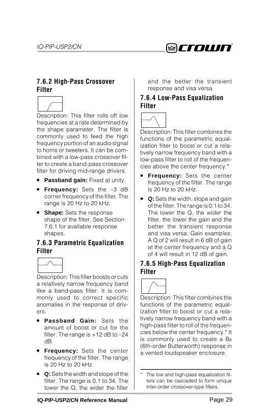
7.6.2 High-Pass CrossoverFilter
Description: This filter rolls off lowfrequencies at a rate determined bythe shape parameter. The filter iscommonly used to feed the highfrequency portion of an audio signalto horns or tweeters. It can be com-bined with a low-pass crossover fil-ter to create a band-pass crossoverfilter for driving mid-range drivers.
••••• Passband gain: Fixed at unity.
••••• Frequency: Sets the –3 dBcorner frequency of the filter. Therange is 20 Hz to 20 kHz.
••••• Shape: Sets the responseshape of the filter. See Section7.6.1 for available responseshapes.
7.6.3 Parametric EqualizationFilter
Description: This filter boosts or cutsa relatively narrow frequency bandlike a band-pass filter. It is com-monly used to correct specificanomalies in the response of driv-ers.
••••• Passband Gain: Sets theamount of boost or cut for thefilter. The range is +12 dB to –24dB.
••••• Frequency: Sets the centerfrequency of the filter. The rangeis 20 Hz to 20 kHz.
••••• Q: Sets the width and slope of thefilter. The range is 0.1 to 34. Thelower the Q, the wider the filter
and the better the transientresponse and visa versa.
7.6.4 Low-Pass EqualizationFilter
Description: This filter combines thefunctions of the parametric equal-ization filter to boost or cut a rela-tively narrow frequency band with alow-pass filter to roll of the frequen-cies above the center frequency.*
••••• Frequency: Sets the centerfrequency of the filter. The rangeis 20 Hz to 20 kHz.
••••• Q: Sets the width, slope and gainof the filter. The range is 0.1 to 34.The lower the Q, the wider thefilter, the lower the gain and thebetter the transient responseand visa versa. Gain examples:A Q of 2 will result in 6 dB of gainat the center frequency and a Qof 4 will result in 12 dB of gain.
7.6.5 High-Pass EqualizationFilter
Description: This filter combines thefunctions of the parametric equal-ization filter to boost or cut a rela-tively narrow frequency band with ahigh-pass filter to roll of the frequen-cies below the center frequency.* Itis commonly used to create a B6
(6th-order Butterworth) response ina vented loudspeaker enclosure.
IQ-PIP-USP2/CN
Page 30 IQ-PIP-USP2/CN Reference Manual
••••• Frequency: Sets the centerfrequency of the filter. The rangeis 20 Hz to 20 kHz.
••••• Q: Sets the width, slope and gainof the filter. The range is 0.1 to 34.The lower the Q, the wider thefilter, the lower the gain and thebetter the transient responseand visa versa. Gain examples:A Q of 2 will result in 6 dB of gainat the center frequency and a Qof 4 will result in 12 dB of gain.
7.6.6 Low-Pass ShelvingEqualization Filter
Description: This filter boosts or cutslow frequencies by the specifiedamount of gain. When used to cutrather than boost, the filter acts likea high-pass filter rather than a low-pass filter. It has a fixed 1st-orderslope (6 dB/octave).
••••• Passband Gain: Sets theamount of boost or cut for thefilter. The range is +12 dB to –24dB.
••••• Frequency: Sets the –3 dBcorner frequency of the filter. Therange is 20 Hz to 20 kHz.
7.6.7 High-Pass ShelvingEqualization Filter
Description: This filter boosts or cutshigh frequencies by the specifiedamount of gain. When used to cutrather than boost, the filter acts likea low-pass rather than a high-passfilter. It has a fixed 1st-order slope (6dB/octave). It is commonly used tocompensate for the natural high-
frequency roll-off of constant direc-tivity horns.
••••• Passband Gain: Sets theamount of boost or cut for thefilter. The range is +12 dB to –24dB.
••••• Frequency: Sets the +3 dBcorner frequency of the filter. Therange is 20 Hz to 20 kHz.
7.7 Signal DelaySignal delay can be set for eachchannel. The delay for each channelcan be set using “Coarse” or “Fine”adjustment controls:
••••• “Coarse” Delay: Sets theamount of signal delay. Therange is 0 milliseconds to 500milliseconds in 1 millisecondsteps.
••••• “Fine” Delay: Sets the amount ofsignal delay. The range is 0.6250milliseconds to 100 millisecondsin 20.83 millisecond steps. (Theminimum delay of 0.6250milliseconds is inherent in theDSP system design.)
The net delay through the IQ-PIP-USP2/CN is the sum of the coarseand fine delay settings. Use of bothcontrols provides a means forgreater delay control. For example,the Coarse Delay control can beadjusted to provide cabinet-to-cabi-net alignment, while the Fine Delaycontrol can provide alignment withina cluster or cabinet.
7.8 Peak Voltage LimiterThis limits the peak voltage output ofthe amplifier. There are four param-eters which control this limiter.
IQ-PIP-USP2/CN
Page 31IQ-PIP-USP2/CN Reference Manual
7.8.1 On/OffTurns the limiter on or off.
7.8.2 AttackAttack time is adjustable from 10milliseconds to 1 second per 10 dBof overdrive.
7.8.3 ReleaseRelease rate is adjustable from 100milliseconds to 10 seconds per 10dB or release.
7.8.4 ThresholdAbsolute voltage threshold is ad-justable from 12 Vpk to 255 Vpk in 1volt steps.
7.9 Average PowerLimiterLimits the long-term power outputfrom the amp. The actual outputlimiter threshold is determined byan absolute power threshold andthe nominal load impedance set-ting. There are five parameters whichcontrol this limiter.
7.9.1 On/OffTurns the limiter on or off.
7.9.2 Average PowerThreshold The threshold is adjustable from 10to 1000 watts.*
7.9.3 Nominal LoadImpedanceThe nominal load impedance is ad-justable from 1 to 1000 ohms, andshould be set to correspond to thenominal impedance rating of the load
connected to the respective chan-nel.
7.9.4 Attack TimeAdjustable from 1 second to 30 sec-onds in 1 second increments.
7.9.5 Release TimeAdjustable from 1 second to 30 sec-onds in 1 second increments.
7.10 Clip EliminatorThis limiter eliminates amplifier clip-ping by monitoring IOC signals. Theonly control for this limiter is On/Off.
7.11 Thermal LimiterA thermal limiter is provided to limitamplifier output as a function of avail-able thermal headroom, allowingsmooth system level reduction whilepreventing amplifier overload. Thereare four parameters which controlthis feature:
7.11.1 On/OffTurns the thermal limiter on or off.
7.11.2 ThresholdSets the thermal level, in percent,above which limiting will begin. Therange is from 1 to 100%.
7.11.3 AttenuationSets the amount, in dB, that the inputsignal level will be attenuated foreach percentage point that the ther-mal level exceeds the trigger level.The range is ½ to 6 dB in ½-dBsteps.
7.12 Signal MuteThe output signal of each channelcan be independently muted. Thisfunction typically provides 80 dB ormore of attenuation.
* The average power threshold shouldbe set per the loudspeaker’s “long-term” power rating (consult yourspeaker documentation).
IQ-PIP-USP2/CN
Page 32 IQ-PIP-USP2/CN Reference Manual
7.13 Output Trim ControlsAn output trim control is provided foreach channel to adjust the outputgain after processing, allowing for“make-up” gain to compensate forlosses due to crossovers, etc. Rangeis +12 dB to –80 dB in ½-dB steps.
7.14 Polarity InverterThe polarity of the input signal ofeach channel can be independentlyinverted.
7.15 Tie SwitchThe Tie switch connects all activecompressors and limiters togetherso that any limiting/compression af-fects the signal on both channels,such as would typically be desiredwhen processing stereo signals.
7.16 “Ghost Faders”These indicators let you monitor thesignal path gain where it may differfrom manual gain set on input at-tenuation and output trim as the re-sult of limiting or compression. Theyappear as flying faders “behind” theinput attenuators in IQ for Windows.

IQ-PIP-USP2/CN
Page 33IQ-PIP-USP2/CN Reference Manual
8 Load SupervisionThis section describes theIQ-PIP-USP2/CN Load Supervisionfeatures. These features are ac-cessed via IQ for Windows soft-ware. Please refer to the IQ for Win-dows documentation if you are un-familiar with IQ software.
The Load Supervision feature al-lows real time monitoring of the loadconnected to each amplifier chan-nel. When enabled, the IQ-PIP-USP2/CN continuously monitors the am-plifier output voltage and currentand calculates the long-term aver-age load impedance. The measuredload impedance is comparedagainst user defined high and lowlimits. If either limit is exceeded, thestatus indicator and/or IQ Systemerror reporting functions alert theuser of the problem. There are sixcontrols and two indicators for eachchannel:
8.1 On/OffThis feature turns the Load Supervi-sion feature on or off.
8.2 High LimitThis feature sets the upper boundabove which the system will report a“high” error status.
8.3 Low LimitThis feature sets the lower boundbelow which the system will report a“low” error status.
8.4 Nominal LoadImpedanceThis feature sets the expected aver-age impedance for the connected
load. This value determines the out-put signal level required for test.This parameter is also used by theaverage power limiter to determinethe expected power limit threshold.(see Section 7.9).
8.5 CalculateThe Calculate button invokes an im-pedance calculator. Entering out-put voltage and power will give theexpected impedance.
8.6 Include in StandardError ReportingThis feature enables error reportingso that any high/low status conditionis reported via the IQ System (seeSection 5.9).
8.7 Report to AUXEnables any high/low status condi-tion to be reported via the IQ-PIP-USP2/CN AUX port output (see Sec-tion 4.10).
8.8 Test IndicatorThis indicator lights when the loadsupervision algorithm is actuallyperforming a load impedance cal-culation and test verification.
8.9 Low/Normal/HighIndicatorThis indicator shows the present sta-tus of the load with respect to theuser defined high/low limits.
8.10 Z Avg MonitorReports actual calculated averageload impedance.
IQ-PIP-USP2/CN
Page 34 IQ-PIP-USP2/CN Reference Manual
9 UtilitiesThis section describes theIQ-PIP-USP2/CN Utility features.Some of these features are accessedvia IQ for Windows software. Pleaserefer to the IQ for Windows docu-mentation if you are unfamiliar withIQ software.
9.1 User PresetsThe parameters for all functions canbe saved as presets. A total of tenuser presets can be stored in the IQ-PIP-USP2/CN’s flash memory. Pre-set names are stored on the PIP.
9.2 Memory BackupA memory backup feature is pro-vided which can be disabled, if de-sired. The factory default setting is“enabled.” When enabled, thememory backup stores all run-timeparameters that can be controlledby the IQ software into nonvolatileflash memory. Memory backup oc-curs within 2 seconds after any pa-rameter change. When disabled, allrun-time parameters are returned tothe last backed-up values when-ever the unit loses power.
CAUTION: Care should be taken tobackup “safe” levels for the inputattenuators and output trim controls.Changes made after disablingbackup are not saved; therefore, itis possible for the memory backupfeature to be turned off with “unsafe”levels stored. This may result in sig-nificantly greater system gain thenext time power is re-applied to theIQ-PIP-USP2/CN.
9.3 AUX OutputThe AUX Output delivers 15 VDC at10 mA maximum output whenswitched to logic High, and may becontrolled via software or may beprogrammed to switch when a failcondition is present on any channel.The logic of the AUX Output can beset to either non-inverted (enabledoutput transitions from low to high)or inverted (enabled output transi-tions from high to low).
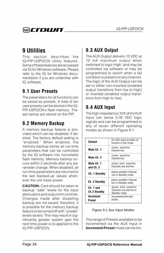
9.4 AUX InputThe high-impedance (10 K ohm) AUXInput can sense 5-35 VDC logicsignals and can be programmed toany of seven different operatingmodes as shown in Figure 9.1:
Default
Mute Ch. 1
Mute Ch. 2
Mute Ch. 1and Ch. 2
Ch. 1 Standby
Ch. 2 Standby
Ch. 1 andCh.2 Standby
IncrementPreset
the AUX Input provides nofunction in this mode.
mutes amplifierChannel one.
mutes amplifierChannel two.
mutes both amplifierChannels one and two.
places amplifier Channelone in Standby mode.
places amplifier Channeltwo in Standby mode.
places both amplifierChannels one and two inStandby mode.increments to the nextpreset.
Figure 9.1 Aux Input Modes
The range of Presets available to beincremented via the AUX Input inIncrement Preset mode can be lim-

IQ-PIP-USP2/CN
Page 35IQ-PIP-USP2/CN Reference Manual
ited to prevent Presets outside a setrange from being selected.* The MinPreset and Max Preset settings al-low minimum and maximum Presetvalues to be specified. In the eventthe AUX Input is engaged while the
* Regardles of the state of the Min Pre-set and Max Preset settings, all Pre-sets are available for selection withinIQ for Windows software.
IQ-PIP-USP2/CN is set in this mode,and the currently-selected Preset isoutside the specified range, the Pre-set will be changed to the minimumPreset value. Once the AUX Inputhas been used to select a Preset inthis mode, it must be toggled to theOFF position and a five-second wait-ing period must occur before a Pre-set can again be selected via theAUX Input.

IQ-PIP-USP2/CN
Page 36 IQ-PIP-USP2/CN Reference Manual
10 Working With IQThis section provides additional in-formation about the IQ System withspecial guides to aid in the installa-tion and use of the IQ-PIP-USP2/CN.
For more information about any ofthese topics, contact the CrownTechnical Support Group.
10.1 A Closer Look at IQAn IQ System is a computerizedsystem which uses the IQ commandprotocol to control and monitor sys-tem functions. An IQ System canmonitor and control audio compo-nents like amplifiers, mixers, andequalizers, but is not limited to au-dio. For example, an IQ System canalso control an auxiliary cooling sys-tem, emergency backup power sys-tem, security system and muchmore.
An IQ System typically consists of aset of IQ components connected toeach other and a host computer.The host computer is typically usedto control and monitor the operationof the connected IQ components,although sometimes it may be re-quired only to set up the system. IQfor Windows is the name of a soft-ware program which runs on thehost computer, and allows you tosetup, control and monitor the com-ponents in an IQ System.
10.1.1 CommunicationsOverviewCommunication in the IQ System isstrictly “client-server” or “speakwhen spoken to.” In other words, allcommunication is initiated by thehost through the interface. A 20mAcurrent loop, called the “IQ Bus,”connects the interface and all IQ
components in the system. A com-ponent on the IQ Bus may not initiatecommunication. Only one commandcan be on the IQ Bus at any onetime.
In most cases, a component receivesa message much like a radio re-ceives a broadcast. A message sentfrom the interface is simultaneouslyreceived by all components on theIQ Bus and also at the IN connectorof the interface at the end of the IQBus.
A component can also send a re-sponse down the IQ Bus. This re-sponse passes through all “down-stream” components, then throughthe IN connector of the interface. AllIQ components have the ability toblock or “open” the IQ Bus.
To communicate with an IQ compo-nent, the host sends a command viaits RS-232 port to the interface. Theinterface collects and buffers thecommand, waiting until it has theentire command. This command isthen transmitted out to the IQ Bus. Acommand that is transmitted is alsosimultaneously received in the inter-face receive side along with anyresponses from any IQ components.This response is then returned to thehost via the RS-232 port.
IQ-PIP-USP2/CN
Page 37IQ-PIP-USP2/CN Reference Manual
* IQ for Windows is compatible with any32-bit Windows operating system. It isnot compatible with older Windows 3.xoperating systems.
10.1.2 IQ2 Protocol (UCode)IQ2 is an advanced type of IQ com-mand protocol developed primarilyto allow third party IQ manufactur-ers to more quickly and easily pro-duce compatible products that donot require intense software pro-gramming. Components that aredesigned with or are otherwise com-patible with UCode protocol carrythe IQ2 logo.
10.1.3 IQ for WindowsIQ for Windows is a Microsoft® Win-dows® 32-bit-compatible applica-tion for operating an IQ System. Itoffers the friendly look and feel ofWindows with the power of IQ. Inaddition to control and monitoring ofIQ components in a Windows envi-ronment, it also offers TCP/IP net-work support and numerous othercapabilities.
For more information about IQ forWindows, see the online documen-tation that accompanies the pro-gram, or visit the IQ website atwww.iqaudiosystems.com/.
10.1.4 IQNETCrown IQNET describes the abilityof IQ for Windows to communicatewith one or more remote systemsusing a network connection. It makes
use of the TCP/IP protocol servicesbuilt into Windows and can run overany network that can be configuredunder Windows.*
IQNET requires the use of an addi-tional software package calledIQNETServer which runs on a com-puter connected to the IQ Systemvia the serial port. Any number ofadditional computers can accessthese systems as network clientsusing IQ for Windows software.
In IQNET, the computer connectedto the IQ System via serial port iscalled the server. A client is anycomputer on the same network run-ning IQ for Windows in network cli-ent mode. The server acts as a gate-way between the parts of an IQSystem and client computers thatare able to control and monitor thatsystem.
For more information about IQ forWindows, see the online documen-tation that accompanies the pro-gram, or visit the IQ website atwww.iqaudiosystems.com.
IQ-PIP-USP2/CN
Page 38 IQ-PIP-USP2/CN Reference Manual
10.2 IQ-PIP-USP2/CNUser InterfacePlease note: It is assumed thereader has a basic familiarity with IQfor Windows. For more informationabout IQ for Windows, see the onlinedocumentation that accompaniesthe program, or visit the IQ websiteat www.iqaudiosystems.com.
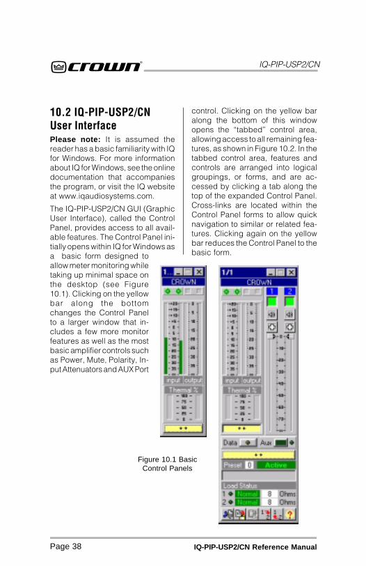
The IQ-PIP-USP2/CN GUI (GraphicUser Interface), called the ControlPanel, provides access to all avail-able features. The Control Panel ini-tially opens within IQ for Windows asa basic form designed toallow meter monitoring whiletaking up minimal space onthe desktop (see Figure10.1). Clicking on the yellowbar along the bottomchanges the Control Panelto a larger window that in-cludes a few more monitorfeatures as well as the mostbasic amplifier controls suchas Power, Mute, Polarity, In-put Attenuators and AUX Port
control. Clicking on the yellow baralong the bottom of this windowopens the “tabbed” control area,allowing access to all remaining fea-tures, as shown in Figure 10.2. In thetabbed control area, features andcontrols are arranged into logicalgroupings, or forms, and are ac-cessed by clicking a tab along thetop of the expanded Control Panel.Cross-links are located within theControl Panel forms to allow quicknavigation to similar or related fea-tures. Clicking again on the yellowbar reduces the Control Panel to thebasic form.
Figure 10.1 BasicControl Panels

IQ-PIP-USP2/CN
Page 39IQ-PIP-USP2/CN Reference Manual
10.2.1 General Control TabThe General Control Tab containscontrols common to most CrownPIPs. These include Stereo/MonoSwitching, Model Selection, Ampli-fier Serial Number, Date Code, UserLabels, Access to “All” commands,8/4 Ohm - 70 volt switching for Crown
Figure 10.2 General Control Tab
Com-Tech “02” amplifiers, AUX In-put Controls for polarity, mode, minpreset and max preset and Firm-ware Program Version number. Fig-ure 10.2 shows the General ControlTab.
IQ-PIP-USP2/CN
Page 40 IQ-PIP-USP2/CN Reference Manual
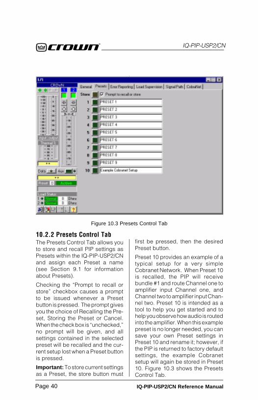
10.2.2 Presets Control TabThe Presets Control Tab allows youto store and recall PIP settings asPresets within the IQ-PIP-USP2/CNand assign each Preset a name(see Section 9.1 for informationabout Presets).
Checking the “Prompt to recall orstore” checkbox causes a promptto be issued whenever a Presetbutton is pressed. The prompt givesyou the choice of Recalling the Pre-set, Storing the Preset or Cancel.When the check box is “unchecked,”no prompt will be given, and allsettings contained in the selectedpreset will be recalled and the cur-rent setup lost when a Preset buttonis pressed.
Important: To store current settingsas a Preset, the store button must
Figure 10.3 Presets Control Tab
first be pressed, then the desiredPreset button.
Preset 10 provides an example of atypical setup for a very simpleCobranet Network. When Preset 10is recalled, the PIP will receivebundle #1 and route Channel one toamplifier input Channel one, andChannel two to amplifier input Chan-nel two. Preset 10 is intended as atool to help you get started and tohelp you observe how audio is routedinto the amplifier. When this examplepreset is no longer needed, you cansave your own Preset settings inPreset 10 and rename it; however, ifthe PIP is returned to factory defaultsettings, the example Cobranetsetup will again be stored in Preset10. Figure 10.3 shows the PresetsControl Tab.
IQ-PIP-USP2/CN
Page 41IQ-PIP-USP2/CN Reference Manual
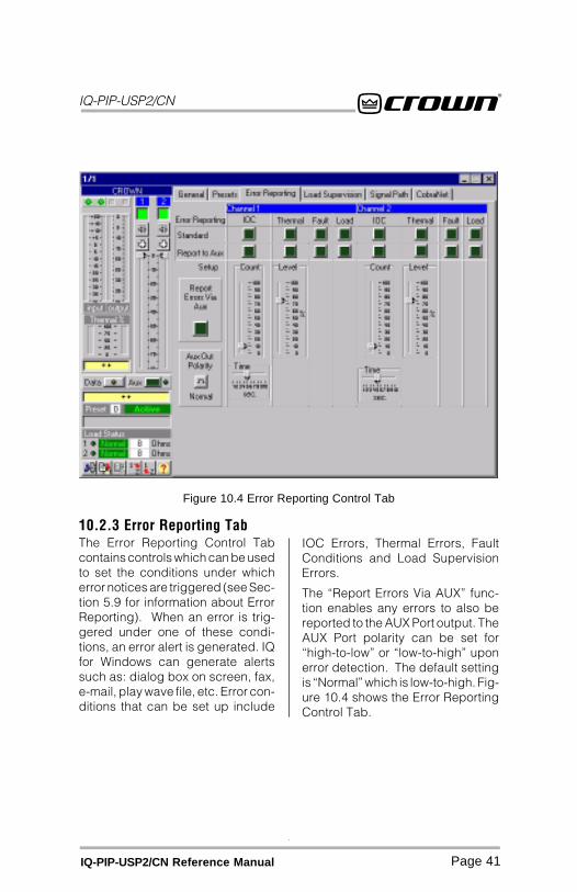
10.2.3 Error Reporting TabThe Error Reporting Control Tabcontains controls which can be usedto set the conditions under whicherror notices are triggered (see Sec-tion 5.9 for information about ErrorReporting). When an error is trig-gered under one of these condi-tions, an error alert is generated. IQfor Windows can generate alertssuch as: dialog box on screen, fax,e-mail, play wave file, etc. Error con-ditions that can be set up include
Figure 10.4 Error Reporting Control Tab
IOC Errors, Thermal Errors, FaultConditions and Load SupervisionErrors.
The “Report Errors Via AUX” func-tion enables any errors to also bereported to the AUX Port output. TheAUX Port polarity can be set for“high-to-low” or “low-to-high” uponerror detection. The default settingis “Normal” which is low-to-high. Fig-ure 10.4 shows the Error ReportingControl Tab.
IQ-PIP-USP2/CN
Page 42 IQ-PIP-USP2/CN Reference Manual
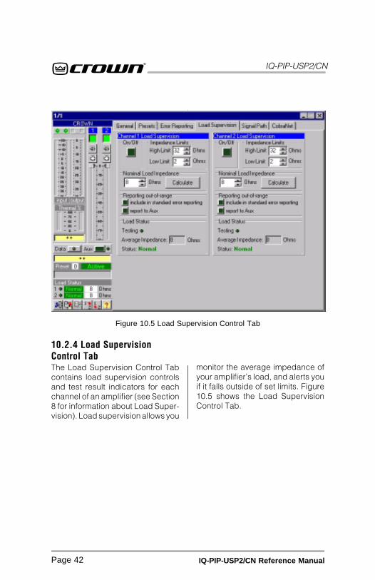
10.2.4 Load SupervisionControl TabThe Load Supervision Control Tabcontains load supervision controlsand test result indicators for eachchannel of an amplifier (see Section8 for information about Load Super-vision). Load supervision allows you
Figure 10.5 Load Supervision Control Tab
monitor the average impedance ofyour amplifier’s load, and alerts youif it falls outside of set limits. Figure10.5 shows the Load SupervisionControl Tab.
IQ-PIP-USP2/CN
Page 43IQ-PIP-USP2/CN Reference Manual
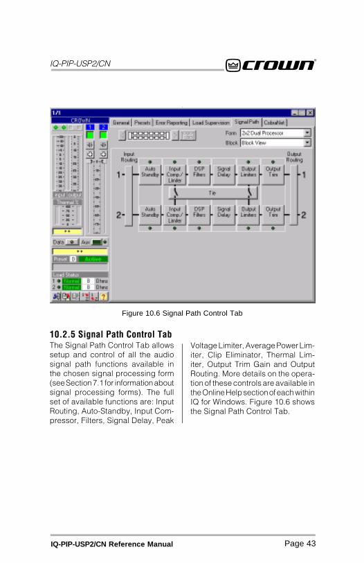
10.2.5 Signal Path Control TabThe Signal Path Control Tab allowssetup and control of all the audiosignal path functions available inthe chosen signal processing form(see Section 7.1 for information aboutsignal processing forms). The fullset of available functions are: InputRouting, Auto-Standby, Input Com-pressor, Filters, Signal Delay, Peak
Figure 10.6 Signal Path Control Tab
Voltage Limiter, Average Power Lim-iter, Clip Eliminator, Thermal Lim-iter, Output Trim Gain and OutputRouting. More details on the opera-tion of these controls are available inthe Online Help section of each withinIQ for Windows. Figure 10.6 showsthe Signal Path Control Tab.
IQ-PIP-USP2/CN
Page 44 IQ-PIP-USP2/CN Reference Manual
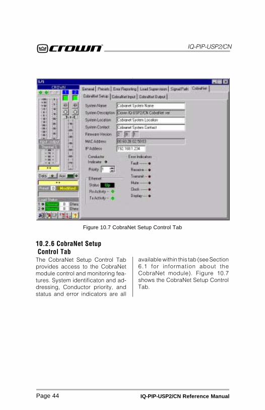
10.2.6 CobraNet Setup Control TabThe CobraNet Setup Control Tabprovides access to the CobraNetmodule control and monitoring fea-tures. System identificaton and ad-dressing, Conductor priority, andstatus and error indicators are all
available within this tab (see Section6.1 for information about theCobraNet module). Figure 10.7shows the CobraNet Setup ControlTab.
Figure 10.7 CobraNet Setup Control Tab
IQ-PIP-USP2/CN
Page 45IQ-PIP-USP2/CN Reference Manual
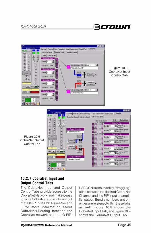
Figure 10.8CobraNet Input
Control Tab
Figure 10.9CobraNet Output
Control Tab
10.2.7 CobraNet Input andOutput Control TabsThe CobraNet Input and OutputControl Tabs provide access to theCobraNet Network,and make it easyto route CobraNet audio into and outof the IQ-PIP-USP2/CN (see Section6 for more information aboutCobraNet).Routing between theCobraNet network and the IQ-PIP-
USP2/CN is achieved by “dragging”a line between the desired CobraNetChannel and the PIP input or ampli-fier output. Bundle numbers and pri-orities are assigned within these tabsas well. Figure 10.8 shows theCobraNet Input Tab, and Figure 10.9shows the CobraNet Output Tab.

IQ-PIP-USP2/CN
Page 46 IQ-PIP-USP2/CN Reference Manual
10.3 IQ Bus WiringThe IQ-PIP-USP2/CN must be con-nected to a IQ Bus loop having anIQ2-compatible IQ interface in or-der for the IQ System to control ormonitor it. The IQ Bus is a serialcommunication loop designed totransmit IQ commands and data. Asimplemented in the IQ-PIP-USP2/CN, it is a 20 milliamp current loopoperating at a BAUD rate of 38.4 K.The loop must be unbroken to func-tion properly.
If the system includes an IQ–INT IIinterface, it can accept eight differ-ent IQ Bus loops or zones. Dividingthe sound system into differentzones, each with its own IQ Busloop, can have several advantages.The following list contrasts thoseadvantages with those of a singleloop.
Multiloop Advantages
• A break in communication in oneloop does not affect other loops.
• Over 250 IQ components of thesame type can be used in asystem.
• The same IQ address can beused more than once (once perloop per model).
Single Loop Advantages(with IQ-INT II interfaces)
• The IQ System can send andretrieve data faster in a singleloop.
• “Real time” level display of agreater number of units ispossible.
The IQ-PIP-USP2/CN can be con-nected to the IQ Bus with inexpen-
sive twisted-pair wiring (shielded orunshielded). If fiber optic wiring isrequired contact the Crown Techni-cal Support Group (see page 2).
Here are some guidelines for twisted-pair wiring:
• Use shielded twisted-pair wireat least 26 AWG in size wheninterference is a problem. Thewire should be of good qualityand should have lowcapacitance—30 picofarads/foot or less is good. (West Penn452 or an equivalent wire workswell.) The shield serves twopurposes: First, it helps preventthe IQ data signal fromtransmitting to nearby audiowiring. Second, it helps preventoutside RF from interfering withthe data signal. However, in mostcases interference is not aproblem and, since unshieldedwire has lower capacitance, it isa better choice.
• Minimize the total capacitanceof each IQ Bus loop. The totalcapacitance should be less than30 nanofarads. Allow forapproximately 60 picofarads foreach IQ component in a loop.This accounts for a slight delaywhich occurs as data signalspass through a component.
• Add an IQ Repeater for verylong loops—greater than 1,000feet (305 m)—or when requiredby high-capacitance wire.Although we recommend arepeater for loops longer than1,000 feet, it is often possible togo 2,000 feet (610 m) or more.The most significant characteristicof the wire is its capacitance.
IQ-PIP-USP2/CN
Page 47IQ-PIP-USP2/CN Reference Manual
10.4 A Closer Look atCobraNetCobraNet is a licensed technologydeveloped by Peak Audio, Inc. con-sisting of proprietary communica-tions protocol, firmware and hard-ware. It allows reliable, determinis-tic transmission of digital audio overa 100Base-T Fast-Ethernet network.
This section provides an overview ofCobraNet. Peak Audio has provideda number of technical papers thatdescribe CobraNet in detail. Thesepapers are available at:http://www.PeakAudio.com/CobraNet/.
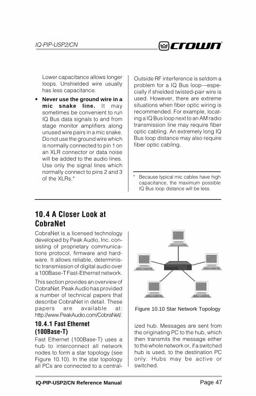
10.4.1 Fast Ethernet(100Base-T)Fast Ethernet (100Base-T) uses ahub to interconnect all networknodes to form a star topology (seeFigure 10.10). In the star topologyall PCs are connected to a central-
ized hub. Messages are sent fromthe originating PC to the hub, whichthen transmits the message eitherto the whole network or, if a switchedhub is used, to the destination PConly. Hubs may be active orswitched.
* Because typical mic cables have highcapacitance, the maximum possibleIQ Bus loop distance will be less.
Lower capacitance allows longerloops. Unshielded wire usuallyhas less capacitance.
• Never use the ground wire in amic snake line. It maysometimes be convenient to runIQ Bus data signals to and fromstage monitor amplifiers alongunused wire pairs in a mic snake.Do not use the ground wire whichis normally connected to pin 1 onan XLR connector or data noisewill be added to the audio lines.Use only the signal lines whichnormally connect to pins 2 and 3of the XLRs.*
Outside RF interference is seldom aproblem for a IQ Bus loop—espe-cially if shielded twisted-pair wire isused. However, there are extremesituations when fiber optic wiring isrecommended. For example, locat-ing a IQ Bus loop next to an AM radiotransmission line may require fiberoptic cabling. An extremely long IQBus loop distance may also requirefiber optic cabling.
Figure 10.10 Star Network Topology
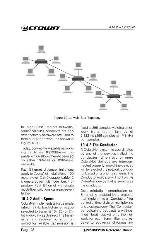
IQ-PIP-USP2/CN
Page 48 IQ-PIP-USP2/CN Reference Manual
In larger Fast Ethernet networks,additional hubs, concentrators, andother network hardware are used toform a larger network, as shown inFigure 10.11.
Today, commonly available network-ing cards are 10/100Base-T ca-pable, which allows them to be usedon either 10BaseT or 100Base-Tnetworks.
Fast Ethernet distance limitationsapply to CobraNet installations: 100meters over Cat-5 copper cable, 2kilometers over multimode fiber. Pro-prietary Fast Ethernet via singlemode fiber solutions can reach evenfurther.
10.4.2 Audio SpecsCobraNet implements a fixed samplerate of 48 kHz. Each channel may beselected to transmit 16-, 20- or 24-bit audio data as desired. The trans-mitter and receiver buffering re-quired for reliable transmission is
fixed at 256 samples yielding a net-work transmission latency of5.333 ms (256 samples at 1/48 kHzper sample).
10.4.3 The ConductorA CobraNet system is coordinatedby one of the devices called theconductor. When two or moreCobraNet devices are intercon-nected properly, one of the deviceswill be elected the network conduc-tor based on a priority scheme. TheConductor indicator will light on theCobraNet device that is serving asthe conductor.
Deterministic transmission onEthernet is enabled by a protocolthat implements a “Conductor” forcontrol of time-division multiplexingand clock recovery. The “Conductor”periodically broadcasts a well-de-fined “beat” packet onto the net-work for each transmitter and re-ceiver to recover synchronous tim-
Figure 10.11 Multi-Star Topology

IQ-PIP-USP2/CN
Page 49IQ-PIP-USP2/CN Reference Manual
ing information. The “beat” alsoincludes information as to whichaddresses can transmit at certaintime slots within the “beat” period.
The Conductor regulates theCobraNet digital audio traffic on theCobraNet network. Each transmitteris given a “permission” to transmit ina given time-slot within the Conduc-tor controlled isochronous cycle-time. The time-slot is determined bythe assigned bundle priority. Higherbundle priorities receive lower-num-bered positions and are transmittedfirst. The “Receiver Count” monitorindicates how many devices arerecieving the digital audio bundle.The “Active” indicator indicateswhether the particular Bundle isbeing actively transmitted onto thenetwork.
10.4.4 Bundles and AudioChannelsAll audio channels are packagedinto groups called Bundles (formerlycalled Network Channels) for trans-mission over the Ethernet network.Each CobraNet device has the abil-ity to send and receive a fixed num-ber of Bundles. The Bundle numbertells the CobraNet conductor whichspecific CobraNet device is tryingto communicate with which otherCobraNet device(s) over the net-work. A given Bundle may have onlyone transmitter that places it ontothe network. Unicast Bundles mayhave only a single receiver. MulticastBundles may have multiple receiv-ers.
Bundles from 1 to 255 are desig-nated as “multi-cast” Bundles. Thismeans that they are transmitted tomultiple receivers. This type is most
used on “repeater” networks limitedto 64 channels.
Bundles from 256 to 65,279 are “uni-cast”. This means that they are trans-mitted to one and only one receiver.This type is most used on “switched”networks requiring more than 64channels.
A Bundle can carry up to 8 audiochannels (see the block diagram inSection 10.10). The usual assign-ment is 8 channels at 20 bits. Usingless audio channels is possible butmaximum size bundles are sug-gested for most efficient utilizationof network bandwidth. If 24 bit datais desired, then only 7 audio chan-nels can be loaded into a singleBundle.
10.4.5 Repeater NetworksCobraNet can operate on “repeater”networks and more complex“switched” networks. Repeater net-works use low-cost Ethernet hubs.*On this type of an Ethernet network,all packets are broadcast to all con-nected nodes. CobraNet multi-castand uni-cast Bundles can be as-signed but because of the simplerrepeater-type hubs, even uni-casttransmissions are broadcast to allnodes. Therefore, a maximum of 8full-loaded Bundles (64 audio chan-nels) are allowed on the entire net-work. More Bundles may be allowedif they are loaded with less than thefull eight audio channels. There isno limit to the number of active re-ceivers on a repeater network. Gen-erally, a repeater based CobraNet
* See Tested Ethernet Products on thePeak Audio website for a list of recom-mended Ethernet repeaters.
IQ-PIP-USP2/CN
Page 50 IQ-PIP-USP2/CN Reference Manual
10.5 Using the AUXConnectorThe IQ-PIP-USP2/CN AUX Connec-tor adds tremendous flexibility tothe IQ System. Its AUX Output ca-pability can be used to turn periph-erals on/off or send a signal to an-other system component. Its AUXInput capability can be used to re-ceive a signal from another compo-
nent and either mute one or bothamplifier channels, place one or bothamplifier channels in standby, orincrement presets.
The AUX connector is an RJ-11 type.Pins 2 and 5 are used to receive asignal and pins 3 and 4 are used tosend a signal.
network must be dedicated toCobraNet traffic only to guaranteereliable transmission of audio pack-ets.
10.4.6 Switched NetworksA more complex CobraNet networkcan be built using EthernetSwitches.* Ethernet switching tech-nology is more sophisticated thanhubs. Switches do not simply broad-cast each and every packet to allnodes. Instead, they can interro-gate each incoming packet trans-mission to determine its destinationand (very quickly) transmit the datato only that destination port. Thisallows for more overall network traf-fic. In effect each port has 100MB ofbandwidth and the overall networkcan be as large as 100MB times thenumber of ports on the network.
Switched networks allow both multi-cast and uni-cast CobraNet Bundles.Uni-cast transmissions can only be
received by a single node and aretypically used for point-to-point rout-ing. This technique leveragesEthernet switching technology to sig-nificantly conserve overall networkbandwidth and in-turn allow manymore Bundles and Audio Channels.
Another enhancement available withmost switched network environ-ments is “full-duplex” links. A full-duplex link allows simultaneous sendand receive over the same Ethernetconnection. This allows simulta-neous send and receive of up to 64channels per node for a total of 128channels. That said, please keep inmind that today’s CobraNet nodedesigns are only capable of 64 chan-nels (32 in and 32 out).
The combination of switching andfull-duplex technologies in switchedCobraNet networks allows up to 128channels per node and greater than3000 individual uni-cast channels.There is no limit to the number ofactive receivers on a switchedCobraNet network. Switched net-works also allow control traffic suchas PCs, to coexist on the same net-work as CobraNet devices.
* See Tested Ethernet Products on thePeak Audio website atwww.peakaudio.com/CobraNet for alist of recommended Ethernetswitches.
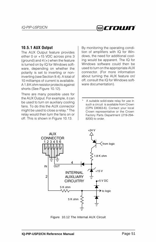
IQ-PIP-USP2/CN
Page 51IQ-PIP-USP2/CN Reference Manual
Figure 10.12 The Internal AUX Circuit
* A suitable solid-state relay for use insuch a circuit is available from Crown(CPN D8063-6). Contact your localCrown representative or the CrownFactory Parts Department (219-294-8200) to order.
10.5.1 AUX OutputThe AUX Output feature provideseither 0 or +15 VDC across pins 3(ground) and 4 (+) when the featureis turned on by IQ for Windows soft-ware, depending on whether thepolarity is set to inverting or non-inverting (see Section 9.4). A total of10 milliamps of current is available.A 1.8 K ohm resistor protects againstshorts (See Figure 10.12).
There are many possible uses forthe AUX Output. For example, it canbe used to turn on auxiliary coolingfans. To do this the AUX connectormight be used to close a relay.* Therelay would then turn the fans on oroff. This is shown in Figure 10.13.
By monitoring the operating condi-tion of amplifiers with IQ for Win-dows, the need for additional cool-ing would be apparent. The IQ forWindows software could then beused to turn on the appropriate AUXconnector. (For more informationabout turning the AUX feature on/off, consult the IQ for Windows soft-ware documentation).

IQ-PIP-USP2/CN
Page 52 IQ-PIP-USP2/CN Reference Manual
* A negative signal can also be used asa logic low because the signal is inter-nally clamped to protect the internalcircuitry.
10.5.2 AUX InputThe AUX connector can be used tosense the presence of an input sig-nal across pins 2 (+) and 5 (ground).Like the AUX Output, the AUX Inputpolarity can be set to either invert-ing or non-inverting. When set tonon-inverting, a +5 to +35 VDC sig-nal at the input is interpreted as alogic “high” and a signal less than+1.6 VDC is interpreted as a logic“low.”* The AUX Input will act on thereceived signals depending uponthe AUX Input operating mode se-lected (see Section 9.4).
Figure 10.13A Sample AUX Output Circuit
10.6 Load SupervisionApplicationsThe IQ-PIP-USP2/CN Load Supervi-sion feature can be used to monitorthe amplifier load in real time withalmost any program material. Aver-age load impedance is calculatedas a function of amplifier output volt-age and current. The system re-quires approximately 20-30 mA ofaverage amplifier output current foradequate supervision. This allowstypically low average output powerlevels of less than ½ watt with mostloads. The maximum load imped-ance for reliable system perfor-mance is limited to about 50 ohms.Higher impedances can be mea-sured but may require higher ampli-fier output levels for reliable opera-tion.
Most amplifier/load systems can beconfigured and supervised by fol-lowing these steps:
1. Configure your audio systemusing a known “good” load, thenenable the Load Supervisionfeature.
2. Provide typical program materialat a level high enough to light the“test” indicator.
3. Run the system at this level untilthe average impedancestabilizes. This may take secondsto minutes depending on level,duty-cycle, etc.
4. Set the nominal impedance at themeasured value average. This
IQ-PIP-USP2/CN
Page 53IQ-PIP-USP2/CN Reference Manual
* These limits are somewhat arbitrarybut should be a good starting point.
optimizes the supervisionalgorithm for voltage and currentlevels versus the actual load.Note: a higher nominal setting willrequire higher output levels.
5. Set the high limit at twice averageand the low limit at one-fourthnominal.*
6. Let the system run for extendedperiods using any and all typicalprogram material.
7. Adjust the high/low limits, ifnecessary, to account for anyvariance in average measuredimpedance.
8. Enable error reporting, if desired.
This procedure should work well formost applications. However, someapplications can be a little moredifficult. Some very low-level and/orlow duty-cycle signals may not ad-equately “test” the load. Lab andsituation testing have shown outputlevels as small 40 dB below ratedamplifier output to be enough formost low-impedance loads. Higherimpedance loads such as those usedin “lightly-loaded” 70V distributionlines may require signal level near20 dB below rated output.
The “Nominal Load Impedance” con-trol is used to optimize the systemfor the most accurate calculation ofload impedance. It should be set tothe expected nominal (or rated) im-pedance of the “normal” load. Thehigh limit should be set for at least 2times the expected nominal or ac-tual measured load, while the lowlimit should be set to ½ the expected
nominal or actual measured load.
The following example calculatesthe SPL necessary for supervisionof a typical 8-ohm system. While theresulting 80-dB SPL @ 1 meter isdefinitely above conversation level,it is not uncomfortable.
An “8 ohm” example:
30 mA into 8 ohms = 0.007watts
8-ohm driver sensitivity = 100 dB for1W @ 1 meter
0.007W/1W = –20 dB
Required SPL for supervision test is100 dB – 20 dB = 80 dB SPL @ 1meter
10.6.1 Typical LoadCharacteristics to Know andUnderstandIt is well known that the typical loud-speaker impedance is not the samefor all frequencies. This variance isdue to the effect of electrical proper-ties such as the expected increasein impedance at high frequenciesdue to driver voice-coil inductance,or the peaks and valleys due topassive crossovers. Testing of vari-ous passive boxes has shown peaksof 100 ohms or more! Low frequencyimpedance variation can come fromthe interaction of the driver compli-ance with that of the box. The lowfrequency variations are usually widebandwidth and may vary from 6 to30 ohms on an 8-ohm driver.
These anomalies are easily aver-aged out by the IQ-PIP-USP2/CNsupervision algorithm in most sys-tems. However, there may be someextreme situations for very narrowbandwidth (i.e. single-note) signalsand/or very widely varying loads
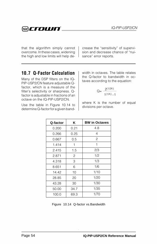
IQ-PIP-USP2/CN
Page 54 IQ-PIP-USP2/CN Reference Manual
10.7 Q-Factor CalculationMany of the DSP filters on the IQ-PIP-USP2/CN feature adjustable Q-factor, which is a measure of thefilter’s selectivity or sharpness. Q-factor is adjustable in fractions of anoctave on the IQ-PIP-USP2/CN.
Use the table in Figure 10.14 todetermine Q-factor for a given band-
width in octaves. The table relatesthe Q-factor to bandwidth in oc-taves according to the equation:
where K is the number of equaldivisions per octave.
Figure 10.14 Q-factor vs.Bandwidth
2(1/2K)
1(1/K) –1Q=
Q-factor
0.200
0.266
0.667
1.414
2.415
2.871
4.318
8.651
14.42
28.85
43.28
50.00
100.0
K
0.21
0.25
0.5
1
1.5
2
3
6
10
20
30
34.7
69.3
BW in Octaves
4.8
4
2
1
2/3
1/2
1/3
1/6
1/10
1/20
1/30
1/35
1/70
that the algorithm simply cannotovercome. In these cases, wideningthe high and low limits will help de-
crease the “sensitivity” of supervi-sion and decrease chance of “nui-sance” error reports.
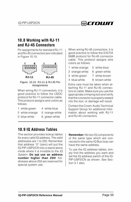
IQ-PIP-USP2/CN
Page 55IQ-PIP-USP2/CN Reference Manual
10.9 IQ Address TablesThis section provides lookup tablesfor every valid IQ address. The validaddresses are 1 to 250. Rememberthat address “0” (zero) will put theIQ-PIP-USP2/CN into a stand-alonemode where it is invisible to the IQSystem. Do not use an addressnumber higher than 250! Ad-dresses above 250 are reserved forspecial system use.
Remember: No two IQ componentsof the same type which are con-nected to the same IQ Bus loop canhave the same address.
To use the IQ address tables, sim-ply find the address you want andset the IQ address switch of the IQ-PIP-USP2/CN as shown. See Sec-tion 3.1 also.
10.8 Working with RJ-11and RJ-45 ConnectorsPin assignments for standard RJ-11and RJ-45 connectors are indicatedin Figure 10.15.
When wiring RJ-45 connectors, it isgood practice to follow the EIA/TIA568B protocol for RJ-45 connectorcable. This protocol assigns wirecolors as follows:
1 white-orange 5 white-blue2 orange-white 6 green-white3 white-green 7 white-brown4 blue-white 8 brown-white
Extra care must be taken when at-taching RJ-11 and RJ-45 connec-tors to cable. Make sure you use theappropriate crimping tool and verifythat the connector is properly seatedinto the tool, or damage will result.
Contact the Crown Audio TechnicalSupport Group for additional infor-mation about working with RJ-11and RJ-45 connectors.
When wiring RJ-11 connectors, it isgood practice to follow the USOCprotocol for RJ-11 connector cable.This protocol assigns wire colors asfollows:
1 white-green 4 white-blue2 white-orange 5 orange-white3 blue-white 6 green-white
RJ-11 RJ-45
Figure 10.15 RJ-11 & RJ-45 PinAssignments
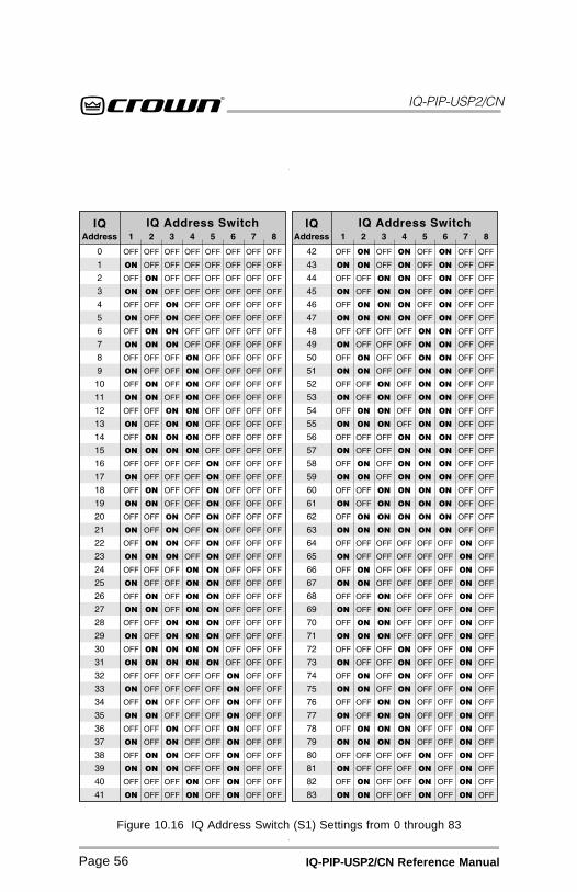
IQ-PIP-USP2/CN
Page 56 IQ-PIP-USP2/CN Reference Manual
Figure 10.16 IQ Address Switch (S1) Settings from 0 through 83

IQ-PIP-USP2/CN
Page 57IQ-PIP-USP2/CN Reference Manual
Figure 10.17 IQ Address Switch (S1) Settings from 84 through 167

IQ-PIP-USP2/CN
Page 58 IQ-PIP-USP2/CN Reference Manual
Figure 10.18 IQ Address Switch (S1) Settings from 168 through 250
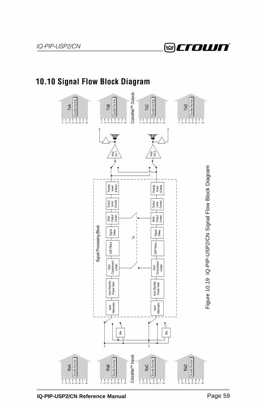
IQ-PIP-USP2/CN
Page 59IQ-PIP-USP2/CN Reference Manual
Fig
ure
10.1
9 I
Q-P
IP-U
SP
2/C
N S
igna
l Flo
w B
lock
Dia
gram
10.10 Signal Flow Block Diagram

IQ-PIP-USP2/CN
Page 60 IQ-PIP-USP2/CN Reference Manual
11 Specifications
11.1 GeneralInternal Controls: An 8-segmentDIP switch sets the IQ address (deci-mal range: 1–250).* A Reset/Presetswitch, accessible with a straight-ened paper clip through the PIPpanel, selects the next user preset ifpressed for less than 2 seconds,resets the PIP to preset “0” if pressedfor more than 2 seconds, or restoresall settings and presets to factorydefault if pressed while applyingpower.
Connectors: IQ Bus: RJ-45 con-nector for input, RJ-45 connector foroutput. AUX In/Aux Out: RJ-11 con-nector. CobraNet Digital Audio In-put and Output: RJ-45 connector forPrimary Network, RJ-45 connectorfor Secondary Network.
Indicators: A yellow DATA indica-tor flashes when a valid IQ com-mand is received from the IQ Sys-tem via the IQ Bus. A green PRESETindicator flashes to indicate the userpreset number currently selected inmemory (if the PRESET indicatordoes not flash the preset numberwhen selected, this indicates thepreset has been modified by theuser). Two dual-color indicators pro-vide status of the CobraNet™ net-work. The left indicator on the Pri-mary and Secondary RJ-45 con-nectors flashes green if the networklink is connected and operating nor-mally, and flashes red if the port is in
* If address “0” is selected, theIQ-PIP-USP2/CN will operate in stand-alone mode. In this mode, the IQ Busport is deactivated.
a “Fault” condition. The right indica-tor on the Primary and SecondaryRJ-45 connectors is ON green if theport is “in-use,” and is ON orange ifthe port is operating as the network“Conductor.”
Memory Backup: 1 Mbyte non-vola-tile FLASH memory for backup ofrun-time parameters, presets, andprogram storage. Capable of greaterthan 10-year data retention and es-timated 20+ year life-cycle.
Power Requirements: Power draw:410 mA @ +24 VDC and 40 mA @ –24 VDC. When installed into a CrownPIP2-compatible amplifier, the unitreceives ±24 VDC from the ampli-fier. No external power is required.
Total Power Dissipation: 10.5 watts.
11.2 IQ Bus DataCommunicationProtection: If IQ communication islost, the unit will continue to functionwith the last commands received.
Data Rate: 38.4 K BAUD.
Data Format: Serial, binary, asyn-chronous; 1 start bit; 1 stop bit; 8data bits; no parity.
IQ Bus Interface Type: Opticallyisolated 20 milliamp serial loop.
Operation: Half duplex.
Transmission Distance: Variablefrom 200 to 3000 feet (61 to 914 m),depending upon wire capacitance.Typically 1000 feet (305 M) usingshielded twisted-pair wire, #26 AWG
IQ-PIP-USP2/CN
Page 61IQ-PIP-USP2/CN Reference Manual
or larger. Can be extended with anIQ Repeater.
11.3 AudioPlease note: The audio specificationsare referenced to 0.775 V (0 dBu).Measurements were made at the out-put of the IQ-PIP-USP2/CN module.
Digital Signal Processor (DSP): 60MHz Motorola 56002 DSP processorprovides 30 million operations persecond.Analog to Digital Conversion(ADC): 24-bit, 48-kHz sample rate,Delta-Sigma converter.
Digital to Analog Conversion(DAC): 24-bit, 48-kHz sample rate,Delta-Sigma converter.
Signal to Noise Ratio: Greater than100 dB (A-weighted, 20 Hz to 20kHz, audio sourced from mutedCobraNet™ channels).
Frequency Response: ±0.5 dB, 20Hz to 20 kHz (referenced to 1 kHz, 0dBu input signal).
Distortion: Less than 0.05%THD+N, 20 Hz to 20 kHz (refer-enced to 1 kHz, 0 dBu input signal).
Crosstalk: better than –80 dB, full-scale input level, 20 Hz to 20 kHzinput frequency sweep, 20 Hz to 20kHz bandwidth.
Listen Bus Distortion: Less than0.1% THD+N, 20 Hz to 20 kHz band-width (1 kHz, 0 dB full scale inputsignal at the active PIP2 AO1 or AO2input).
Listen Bus Signal to Noise: Greaterthan 80 dB, 20 Hz to 20 kHz band-width (audio sourced from mutedamplifier channels. Measured at re-ceiving CobraNet node outputs).
Maximum Output Level: +20 dBu.
11.4 IQ System DataAcquisitionInput/Output Monitor Accuracy:Typically ±1 dB.

IQ-PIP-USP2/CN
Page 62 IQ-PIP-USP2/CN Reference Manual
Crown Audio Customer ServiceTechnical Support / Factory ServicePlant 2 SW, 1718 W. Mishawaka Rd.,Elkhart, Indiana 46517 U.S.A.
Telephone: 219-294-8200800-342-6939(North America,Puerto Rico, andVirgin Islands only)
Facsimile: 219-294-8301(Technical Support)219-294-8124(Factory Service)
Internet: www.crownaudio.comEmail: [email protected]
12 Factory ServiceTo obtain factory service, fill outthe service information pagefound in the back of this manualand send it along with your proofof purchase and the defective unitto the Crown factory.
For warranty service, we will payfor ground shipping both ways inthe United States. Contact CrownFactory Service or Technical Sup-port to obtain prepaid shippinglabels prior to sending the unit.Or, if you prefer, you may prepaythe cost of shipping, and Crownwill reimburse you. Send copies ofthe shipping receipts to Crown toreceive reimbursement.
Your repaired unit will be returnedvia UPS ground. Please contactus if other arrangements are re-quired.
Factory Service ShippingInstructions:1. When sending a Crown product to
the factory for service, be sure to fillout the service information formthat follows and enclose it insideyour unit’s shipping pack. Do notsend the service information formseparately.
2. To ensure the safe transportationof your unit to the factory, ship it inan original factory packingcontainer. If you don’t have one,call or write Crown’s PartsDepartment. With the exception ofpolyurethane or wooden crates,any other packing material will notbe sufficient to withstand thestress of shipping. Do not useloose, small size packingmaterials.
Always use theoriginal factory packto transport the unit.
3. Do not ship the unit in any kind ofcabinet (wood or metal). Ignoringthis warning may result inextensive damage to the unit andthe cabinet. Accessories are notneeded—do not send the productdocumentation, cables and otherhardware.
If you have any questions, pleasecall or write the Crown TechnicalSupport Group.

NORTH AMERICASUMMARY OF WARRANTY
The Crown Audio Division of Crown International, Inc., 1718 West Mishawaka Road,Elkhart, Indiana 46517-4095 U.S.A. warrants to you, the ORIGINAL PURCHASER andANY SUBSEQUENT OWNER of each NEW Crown product, for a period of three (3)years from the date of purchase by the original purchaser (the “warranty period”) thatthe new Crown product is free of defects in materials and workmanship. We furtherwarrant the new Crown product regardless of the reason for failure, except as excludedin this Warranty.
ITEMS EXCLUDED FROM THIS CROWN WARRANTYThis Crown Warranty is in effect only for failure of a new Crown product which occurredwithin the Warranty Period. It does not cover any product which has been damagedbecause of any intentional misuse, accident, negligence, or loss which is coveredunder any of your insurance contracts. This Crown Warranty also does not extend tothe new Crown product if the serial number has been defaced, altered, or removed.
WHAT THE WARRANTOR WILL DOWe will remedy any defect, regardless of the reason for failure (except as excluded),by repair, replacement, or refund. We may not elect refund unless you agree, or unlesswe are unable to provide replacement, and repair is not practical or cannot be timelymade. If a refund is elected, then you must make the defective or malfunctioningproduct available to us free and clear of all liens or other encumbrances. The refundwill be equal to the actual purchase price, not including interest, insurance, closingcosts, and other finance charges less a reasonable depreciation on the product fromthe date of original purchase. Warranty work can only be performed at our authorizedservice centers or at the factory. We will remedy the defect and ship the product fromthe service center or our factory within a reasonable time after receipt of the defectiveproduct at our authorized service center or our factory. All expenses in remedying thedefect, including surface shipping costs in the United States, will be borne by us. (Youmust bear the expense of shipping the product between any foreign country and theport of entry in the United States and all taxes, duties, and other customs fees for suchforeign shipments.)
HOW TO OBTAIN WARRANTY SERVICEYou must notify us of your need for warranty service not later than ninety (90) days afterexpiration of the warranty period. All components must be shipped in a factory pack,which, if needed, may be obtained from us free of charge. Corrective action will betaken within a reasonable time of the date of receipt of the defective product by us orour authorized service center. If the repairs made by us or our authorized servicecenter are not satisfactory, notify us or our authorized service center immediately.
DISCLAIMER OF CONSEQUENTIAL & INCIDENTAL DAMAGESYOU ARE NOT ENTITLED TO RECOVER FROM US ANY INCIDENTAL DAMAGESRESULTING FROM ANY DEFECT IN THE NEW CROWN PRODUCT. THIS INCLUDESANY DAMAGE TO ANOTHER PRODUCT OR PRODUCTS RESULTING FROM SUCHA DEFECT. SOME STSOME STSOME STSOME STSOME STAAAAATES DO NOT ALLOW THE EXCLUSION OR LIMITTES DO NOT ALLOW THE EXCLUSION OR LIMITTES DO NOT ALLOW THE EXCLUSION OR LIMITTES DO NOT ALLOW THE EXCLUSION OR LIMITTES DO NOT ALLOW THE EXCLUSION OR LIMITAAAAATIONS OFTIONS OFTIONS OFTIONS OFTIONS OFINCIDENTINCIDENTINCIDENTINCIDENTINCIDENTAL OR CONSEQUENTIAL DAMAGES, SO THE ABOVE LIMITAL OR CONSEQUENTIAL DAMAGES, SO THE ABOVE LIMITAL OR CONSEQUENTIAL DAMAGES, SO THE ABOVE LIMITAL OR CONSEQUENTIAL DAMAGES, SO THE ABOVE LIMITAL OR CONSEQUENTIAL DAMAGES, SO THE ABOVE LIMITAAAAATION ORTION ORTION ORTION ORTION OREXCLUSION MAEXCLUSION MAEXCLUSION MAEXCLUSION MAEXCLUSION MAY NOT APPLY NOT APPLY NOT APPLY NOT APPLY NOT APPLY TO YOU.Y TO YOU.Y TO YOU.Y TO YOU.Y TO YOU.
WARRANTY ALTERATIONSNo person has the authority to enlarge, amend, or modify this Crown Warranty. ThisCrown Warranty is not extended by the length of time which you are deprived of the useof the new Crown product. Repairs and replacement parts provided under the termsof this Crown Warranty shall carry only the unexpired portion of this Crown Warranty.
DESIGN CHANGESWe reserve the right to change the design of any product from time to time withoutnotice and with no obligation to make corresponding changes in products previouslymanufactured.
LEGAL REMEDIES OF PURCHASERTHIS CROWN WARRANTY GIVES YOU SPECIFIC LEGAL RIGHTS, YOU MAY ALSOHAVE OTHER RIGHTS WHICH VARY FROM STATE TO STATE. No action to enforce thisCrown Warranty shall be commenced later than ninety (90) days after expiration of thewarranty period.
THIS STATEMENT OF WARRANTY SUPERSEDES ANY OTHERSCONTAINED IN THIS MANUAL FOR CROWN PRODUCTS.
9/90
YEAR3
TH
RE
E Y
EA
RFU
LL W
AR
RA
NT
Y
Telephone: 219-294-8200. Facsimile: 219-294-8301

WORLDWIDESUMMARY OF WARRANTY
The Crown Audio Division of Crown International, Inc., 1718 West Mishawaka Road,Elkhart, Indiana 46517-4095 U.S.A. warrants to you, the ORIGINAL PURCHASER andANY SUBSEQUENT OWNER of each NEW Crown1 product, for a period of three (3)years from the date of purchase by the original purchaser (the “warranty period”) thatthe new Crown product is free of defects in materials and workmanship, and we furtherwarrant the new Crown product regardless of the reason for failure, except as excludedin this Crown Warranty.1 Note: If your unit bears the name “Amcron,” please substitute it for the name “Crown”in this warranty.
ITEMS EXCLUDED FROM THIS CROWN WARRANTYThis Crown Warranty is in effect only for failure of a new Crown product which occurredwithin the Warranty Period. It does not cover any product which has been damagedbecause of any intentional misuse, accident, negligence, or loss which is coveredunder any of your insurance contracts. This Crown Warranty also does not extend tothe new Crown product if the serial number has been defaced, altered, or removed.
WHAT THE WARRANTOR WILL DOWe will remedy any defect, regardless of the reason for failure (except as excluded),by repair, replacement, or refund. We may not elect refund unless you agree, or unlesswe are unable to provide replacement, and repair is not practical or cannot be timelymade. If a refund is elected, then you must make the defective or malfunctioningproduct available to us free and clear of all liens or other encumbrances. The refundwill be equal to the actual purchase price, not including interest, insurance, closingcosts, and other finance charges less a reasonable depreciation on the product fromthe date of original purchase. Warranty work can only be performed at our authorizedservice centers. We will remedy the defect and ship the product from the service centerwithin a reasonable time after receipt of the defective product at our authorized servicecenter.
HOW TO OBTAIN WARRANTY SERVlCEYou must notify us of your need for warranty service not later than ninety (90) days afterexpiration of the warranty period. All components must be shipped in a factory pack.Corrective action will be taken within a reasonable time of the date of receipt of thedefective product by our authorized service center. If the repairs made by ourauthorized service center are not satisfactory, notify our authorized service centerimmediately.
DISCLAIMER OF CONSEQUENTIAL & INCIDENTAL DAMAGESYOU ARE NOT ENTITLED TO RECOVER FROM US ANY INCIDENTAL DAMAGESRESULTING FROM ANY DEFECT IN THE NEW CROWN PRODUCT. THIS INCLUDESANY DAMAGE TO ANOTHER PRODUCT OR PRODUCTS RESULTING FROM SUCHA DEFECT.
WARRANTY ALTERATIONSNo person has the authority to enlarge, amend, or modify this Crown Warranty. ThisCrown Warranty is not extended by the length of time which you are deprived of the useof the new Crown product. Repairs and replacement parts provided under the termsof this Crown Warranty shall carry only the unexpired portion of this Crown Warranty.
DESIGN CHANGESWe reserve the right to change the design of any product from time to time withoutnotice and with no obligation to make corresponding changes in products previouslymanufactured.
LEGAL REMEDIES OF PURCHASERNo action to enforce this Crown Warranty shall be commenced later than ninety (90)days after expiration of the warranty period.
THIS STATEMENT OF WARRANTY SUPERSEDES ANY OTHERSCONTAINED IN THIS MANUAL FOR CROWN PRODUCTS.
9/90
TH
RE
E Y
EA
RFU
LL W
AR
RA
NT
YYEAR3
Telephone: 219-294-8200. Facsimile: 219-294-8301

Crown Factory Service InformationShipping Address: Crown Factory Service,
Plant 2 SW, 1718 W. Mishawaka Rd., Elkhart, IN U.S.A. 46517Phone: 1-800-342-6939 or 1-219-294-8200 Fax: 1-219-294-8124
Owner’s Name: __________________________________________________________Shipping Address: ______________________________________________________Phone Number: _______________________ Fax Number: ___________________Model: _______________________________ Serial Number: _________________
Purchase Date: __________________________________________________________
NATURE OF PROBLEM(Be sure to describe the conditions that existed when the
problem occurred and what attempts were made to correct it.)
_______________________________________________________________________
_______________________________________________________________________
_______________________________________________________________________
_______________________________________________________________________
_______________________________________________________________________
Other equipment in your system: __________________________________________
_______________________________________________________________________
_______________________________________________________________________
_______________________________________________________________________
_______________________________________________________________________
If warranty has expired, payment will be:❏❏❏❏❏ Cash/Check ❏❏❏❏❏ VISA ❏❏❏❏❏ MasterCard ❏❏❏❏❏ C.O.D.
Card Number:___________________________
Exp. Date: __________ Signature:____________________________
ENCLOSE THIS PORTION WITH THE UNIT.DO NOT MAIL SEPARATELY.