Embed Size (px)
Citation preview
Working ProjectDraft T10/1355-D
Revision 0919 February 2004
Information technology -SCSI Object-Based Storage Device Commands (OSD)
This is an internal working document of T10, a Technical Committee of Accredited Standards Committee INCITS(InterNational Committee for Information Technology Standards). As such this is not a completed standard and hasnot been approved. The contents may be modified by the T10 Technical Committee. The contents are activelybeing modified by T10. This document is made available for review and comment only.
Permission is granted to members of INCITS, its technical committees, and their associated task groups toreproduce this document for the purposes of INCITS standardization activities without further permission, providedthis notice is included. All other rights are reserved. Any duplication of this document for commercial or for-profituse is strictly prohibited.
T10 Technical Editor: Ralph O. WeberENDL Texas18484 Preston RoadSuite 102 PMB 178Dallas, TX 75252USA
Telephone: 214-912-1373Facsimile: 972-596-2775Email: [email protected]
Funded by Intel Labs
Reference numberISO/IEC 14776-313 : 200x
ANSI INCITS.***:200x
Printed Thursday, February 19, 2004 6:08 PM
Points of Contact:
T10 Chair T10 Vice-ChairJohn B. Lohmeyer George O. PenokieLSI Logic IBM4420 Arrows West Drive 3605 Highway 52 NColorado Springs, CO 80907-3444 MS: 2C6Tel: (719) 533-7560 Rochester, MN 55901Fax: (719) 533-7183 Tel: (507) 253-5208Email: [email protected] Fax: (507) 253-2880
Email: [email protected]
INCITS SecretariatINCITS Secretariat Telephone: 202-737-8888 1250 Eye Street, NW Suite 200 Facsimile: 202-638-4922 Washington, DC 20005 Email: [email protected]
T10 Web Site www.t10.org
T10 Reflector To subscribe send e-mail to [email protected] with ‘subscribe’ in message bodyTo unsubscribe send e-mail to [email protected] with ‘unsubscribe’ in message body
Document DistributionINCITS Online Store http://www.techstreet.com/incits.htmlmanaged by Techstreet Telephone: 1-734-302-7801 or1327 Jones Drive 1-800-699-9277Ann Arbor, MI 48105 Facsimile: 1-734-302-7811
or
Global Engineering http://global.ihs.com/15 Inverness Way East Telephone: 1-303-792-2181 orEnglewood, CO 80112-5704 1-800-854-7179
Facsimile: 1-303-792-2192

19 February 2004 T10/1355-D Revision 09
Revision Information
1 Approved Documents Included
The following T10 approved proposals have been incorporated SPC-3 up to and including this revision:
02-130r0 SBC-2, SSC-2, SMC-2 & OSD Support for All Registrants Persistent Reservations
To the best of the technical editor’s knowledge, the following T10 proposals have been approved for inclusion inSPC-3 but not included in this revision:
none
2 Revision History
2.1 Revision 0 (Gene Milligan)
Initial draft
2.2 Revision 1 (Gene Milligan)
Converted to ISO/IEC style.Edits agreed in 1/2000 T10 meeting.
2.3 Revision 2 (Gene Milligan)
General edits through 5.2.Item 1-d of 00-262r0 per 7/2000 T10 OSD WG.Item 1-e of 00-262r0 per 7/2000 T10 OSD WG.Item 2.1 and 2.3 of 00-262r0 per 7/2000 T10 OSD WG.Item 3.4 of 00-262r0 per 7/2000 T10 OSD WG.Added reservations clause as a point of departure.
Modified abstract partially based upon comments from John Wilkes of HP and made other edits as suggested bysome of his comments.
Eliminating footnotes.
2.4 Revision 3 (Gene Milligan)
Markups from 9/14/2000 T10 working group.T10/00-330r0General edits from 5.3 to the end of the draft.Added acronyms per working group request.Added hierarchy diagram to conventions and model per working group request.
2.5 Revision 4 (4 July 2001)
Editorship assumed and revision 3 converted to FrameMaker [Ralph Weber].Front matter through Clause 3 generally adapted from SPC-2 revision 19 [Ralph Weber].
Working Draft SCSI Object-Based Storage Device Commands (OSD) iii
T10/1355-D Revision 09 19 February 2004
Merge Annex C section 6 (Security) into main draft for community consideration [Garth Gibson].Numerous editorial corrections and editor’s notes added [Ralph Weber].
2.6 Revision 5 (29 March 2002)
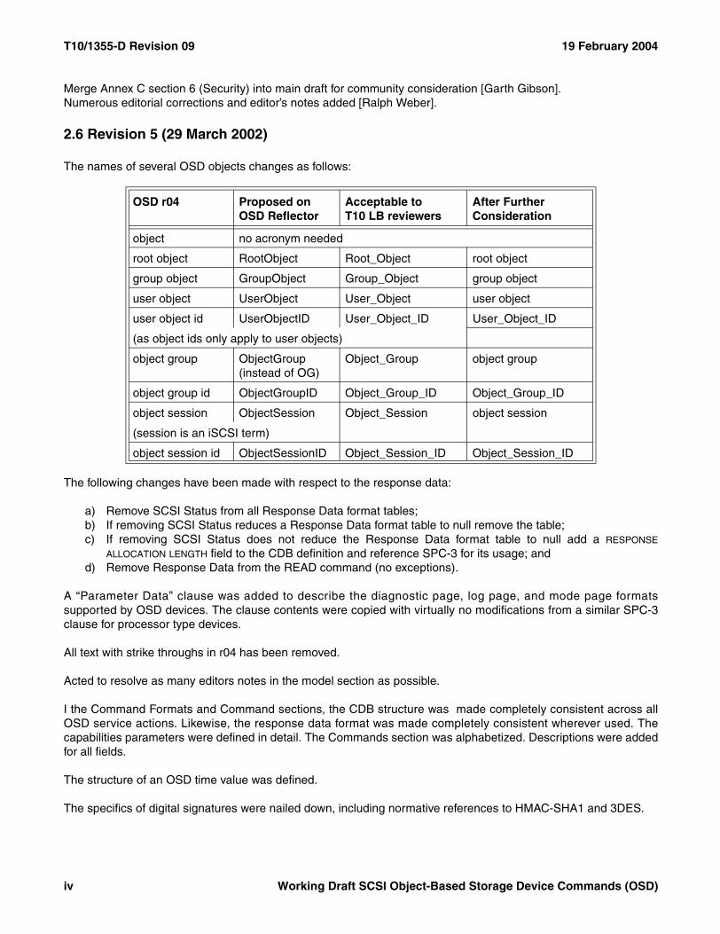
The names of several OSD objects changes as follows:
The following changes have been made with respect to the response data:
a) Remove SCSI Status from all Response Data format tables;b) If removing SCSI Status reduces a Response Data format table to null remove the table;c) If removing SCSI Status does not reduce the Response Data format table to null add a RESPONSE
ALLOCATION LENGTH field to the CDB definition and reference SPC-3 for its usage; andd) Remove Response Data from the READ command (no exceptions).
A “Parameter Data” clause was added to describe the diagnostic page, log page, and mode page formatssupported by OSD devices. The clause contents were copied with virtually no modifications from a similar SPC-3clause for processor type devices.
All text with strike throughs in r04 has been removed.
Acted to resolve as many editors notes in the model section as possible.
I the Command Formats and Command sections, the CDB structure was made completely consistent across allOSD service actions. Likewise, the response data format was made completely consistent wherever used. Thecapabilities parameters were defined in detail. The Commands section was alphabetized. Descriptions were addedfor all fields.
The structure of an OSD time value was defined.
The specifics of digital signatures were nailed down, including normative references to HMAC-SHA1 and 3DES.
OSD r04 Proposed on OSD Reflector
Acceptable toT10 LB reviewers
After Further Consideration
object no acronym needed
root object RootObject Root_Object root object
group object GroupObject Group_Object group object
user object UserObject User_Object user object
user object id UserObjectID User_Object_ID User_Object_ID
(as object ids only apply to user objects)
object group ObjectGroup(instead of OG)
Object_Group object group
object group id ObjectGroupID Object_Group_ID Object_Group_ID
object session ObjectSession Object_Session object session
(session is an iSCSI term)
object session id ObjectSessionID Object_Session_ID Object_Session_ID
iv Working Draft SCSI Object-Based Storage Device Commands (OSD)
19 February 2004 T10/1355-D Revision 09
A PRIORITY field was added to the READ, WRITE, and APPEND service actions, as hinted at in the description ofthe READ command.
The LIST service action was given a CDB format.
The FORMAT OSD service action was given response data.
A CREATE AND WRITE service action was added so that the ATTRIBUTES MASK field could be dropped from itsCDB format. One command cannot both write user data and include a parameter list and the presence of anATTRIBUTES MASK field implies the need for a parameter list (see the SET ATTRIBUTES service action).
In numerous places, 'object' was changed to 'user object' because it appeared that the usage of 'object' was notintended to include the root object or any specific group objects.
2.7 Revision 6 (23 August 2002)
Revision 6 incorporates the following T10 approved proposals:
02-130r0 SBC-2, SSC-2, SMC-2 & OSD Support for All Registrants Persistent Reservations
The major effort in revision 6 is the definition of attribute pages and attribute lists. Also, all commands have beengiven the ability to get and set attributes, with parameter and data transfer commands having a slightly morerestricted ability than commands that do not transfer parameters or data. The necessary changes appear in themodel, commands, and parameter data clauses with the bulk of the changes in the parameter data clauses.
Revision 6 contains an agreed root, group, and user object addressing mechanism. As part of the agreement, theconcept of a default object group has been removed.
2.8 Revision 7 (10 June 2003)
A requested USER_OBJECT_ID field was added to the CREATE and CREATE AND WRITE service actions thusallowing application clients to request assignment of a specific User_Object_ID value to a newly created userobject.
Per an October, 2002 agreement, Annex E “Motivation for the NSIC OSD” was removed.
The description of the expiration time field in the capability parameters was changed to reference the clock attributein the Root Information attributes page. The definition of the OSD clock was moved from the model to the RootInformation attributes page in r06 and the reference to a nonexistent model clause was only caught during r07editing.
The “Notation for Procedure Calls” subclause (3.5) was updated to match the revisions found in SPC-3 r13. An theRequest-Response Model subclause was copied from SPC-3 to the OSD model clause.
The way in which the Data-In Buffer and Data-Out Buffer are segmented between meta data and user data wasreorganized and placed in a new OSD model subclause.
2.9 Revision 7a (16 June 2003)
Revision 7a is identical to revision 7 except that strikethrough text has removed. In some cased the removal ofstrikethrough text may result in extra spaces appearing in unusual places. This will be corrected with thestrikethrough text is removed permanently.
Working Draft SCSI Object-Based Storage Device Commands (OSD) v
T10/1355-D Revision 09 19 February 2004
2.10 Revision 8 (4 September 2003)
Revised as described in 02-275r4 [Changes requested between OSD r07a and r08].
2.11 Revision 9 (19 February 2004)
Revised as described in 04-004r3 [OSD r09 Work List].
Also made numerous editorial changes requested during T10 editing meetings in November and January.
vi Working Draft SCSI Object-Based Storage Device Commands (OSD)
ANSI (r)INCITS.***:200x
American National Standardsfor Information Systems -
SCSI Object-Based Storage Device Commands (OSD)
SecretariatNational Committee for Information Technology Standards
Approved mm dd yy
American National Standards Institute, Inc.
Abstract
This SCSI command set is designed to provide efficient peer-to-peer operation of input/output logical units thatmanage the allocation, placement, and accessing of variable-size data-storage containers, called objects. Objectsare intended to contain operating system and application constructs.
Draft
Draft
Published byAmerican National Standards Institute11 West 42nd Street, New York, NY 10036
Copyright 2/19/04 by American National Standards InstituteAll rights reserved.
Printed in the United States of America
AmericanNationalStandard
Approval of an American National Standard requires verification by ANSI that the require-ments for due process, consensus, and other criteria for approval have been met by thestandards developer. Consensus is established when, in the judgment of the ANSI Boardof Standards Review, substantial agreement has been reached by directly and materiallyaffected interests. Substantial agreement means much more than a simple majority, butnot necessarily unanimity. Consensus requires that all views and objections be consideredand that effort be made toward their resolution.
The use of American National Standards is completely voluntary; their existence does notin any respect preclude anyone, whether he or she has approved the standards or not,from manufacturing, marketing, purchasing, or using products, processes, or proceduresnot confirming to the standards.
The American National Standards Institute does not develop standards and will in nocircumstances give interpretation on any American National Standard in the name of theAmerican National Standards Institute. Requests for interpretations should be addressedto the secretariat or sponsor whose name appears on the title page of this standard.
CAUTION NOTICE: This American National Standard may be revised or withdrawn at anytime. The procedures of the American National Standards Institute require that action betaken periodically to reaffirm, revise, or withdraw this standard. Purchasers of AmericanNational Standards may receive current information on all standards by calling or writingthe American National Standards Institute.
CAUTION: The developers of this standard have requested that holders of patents that may be required for theimplementation of the standard, disclose such patents to the publisher. However, neither the developers northe publisher have undertaken a patent search in order to identify which, if any, patents may apply to thisstandard.
As of the date of publication of this standard and following calls for the identification of patents that may berequired for the implementation of the standard, no such claims have been made. No further patent search isconducted by the developer or the publisher in respect to any standard it processes. No representation ismade or implied that licenses are not required to avoid infringement in the use of this standard.
Draft
19 February 2004 T10/1355-D Revision 09
ContentsPage
Foreword................................................................................................................................................................ xvii
Introduction ............................................................................................................................................................. xix
1 Scope..................................................................................................................................................................... 1
2 Normative references............................................................................................................................................. 42.1 Normative references ................................................................................................................................... 42.2 Approved ISO references ............................................................................................................................. 42.3 Approved FIPS references ........................................................................................................................... 42.4 Approved IETF References .......................................................................................................................... 42.5 References under development ................................................................................................................... 5
3 Definitions, symbols, abbreviations, and conventions ............................................................................................ 63.1 Definitions..................................................................................................................................................... 63.2 Acronyms...................................................................................................................................................... 93.3 Keywords...................................................................................................................................................... 93.4 Conventions................................................................................................................................................ 103.5 Bit and byte ordering .................................................................................................................................. 113.6 Notation conventions .................................................................................................................................. 113.6.1 Notation for byte encoded character strings............................................................................................ 113.6.2 Notation for procedure calls..................................................................................................................... 123.7 Data field requirements .............................................................................................................................. 133.7.1 ASCII data field requirements.................................................................................................................. 133.7.2 Data field termination and padding requirements.................................................................................... 13
4 SCSI OSD Model ................................................................................................................................................. 144.1 The request-response model...................................................................................................................... 144.2 OSD type devices....................................................................................................................................... 144.3 OSD object abstraction............................................................................................................................... 154.4 Elements of the example configuration ...................................................................................................... 164.5 Description of the OSD Architecture........................................................................................................... 174.6 Stored data objects..................................................................................................................................... 174.6.1 Stored data object types.......................................................................................................................... 174.6.2 Identifying OSD objects ........................................................................................................................... 184.6.3 Root object .............................................................................................................................................. 184.6.4 Partitions.................................................................................................................................................. 184.6.5 User objects............................................................................................................................................. 194.6.6 Collections ............................................................................................................................................... 194.7 OSD object attributes ................................................................................................................................. 204.7.1 Overview.................................................................................................................................................. 204.7.2 Command function ordering for commands that get and/or set attributes............................................... 204.7.3 Attributes pages....................................................................................................................................... 214.7.4 Attributes ................................................................................................................................................. 224.7.5 Attributes directories................................................................................................................................ 234.8 Quotas ........................................................................................................................................................ 234.8.1 Introduction.............................................................................................................................................. 234.8.2 Quota errors ............................................................................................................................................ 244.8.3 Quota testing ........................................................................................................................................... 244.8.4 Changing quotas ..................................................................................................................................... 244.9 Security....................................................................................................................................................... 24
Working Draft SCSI Object-Based Storage Device Commands (OSD) ix
T10/1355-D Revision 09 19 February 2004
4.9.1 Basic security model................................................................................................................................ 244.9.2 Trust assumptions ................................................................................................................................... 264.9.3 Security methods..................................................................................................................................... 264.9.3.1 Introduction........................................................................................................................................... 264.9.3.2 The NOSEC security method ............................................................................................................... 274.9.3.3 The CAPKEY security method ............................................................................................................. 274.9.3.4 The CMDRSP security method ............................................................................................................ 284.9.3.5 The ALLDATA security method ............................................................................................................ 294.9.4 Credentials and capabilities..................................................................................................................... 324.9.4.1 Credential format .................................................................................................................................. 324.9.4.2 Capability key ....................................................................................................................................... 324.9.4.3 Capability format................................................................................................................................... 334.9.4.4 Credentials and commands allowed..................................................................................................... 374.9.5 OSD device server security algorithms ................................................................................................... 444.9.5.1 Determining the security method to use for processing a command.................................................... 444.9.5.2 Credential and capability validation ...................................................................................................... 454.9.5.3 Reconstructing the credential ............................................................................................................... 464.9.5.4 Computing the credential integrity check value .................................................................................... 464.9.5.5 Invalidating credentials ......................................................................................................................... 474.9.6 Request nonces....................................................................................................................................... 474.9.6.1 Request nonce format .......................................................................................................................... 474.9.6.2 Device server validation of request nonces.......................................................................................... 484.9.6.3 Far-in-the-future nonces ....................................................................................................................... 494.9.6.3.1 Introduction........................................................................................................................................ 494.9.6.3.2 Capability restrictions with far in the future nonces ........................................................................... 494.9.6.3.3 Working key restrictions with far in the future nonces ....................................................................... 494.9.7 Integrity check values .............................................................................................................................. 494.9.8 Secret keys.............................................................................................................................................. 504.9.8.1 Introduction........................................................................................................................................... 504.9.8.2 Credentials for SET KEY and SET MASTER KEY commands ............................................................ 514.9.8.3 Computing updated generation keys and new authentication keys ..................................................... 524.9.9 OSD security interactions with SPC-3 commands and SAM-3 task management functions .................. 524.10 Data persistence model............................................................................................................................ 534.11 Data-In and Data-Out Buffer model.......................................................................................................... 544.11.1 OSD meta data...................................................................................................................................... 544.11.2 OSD Data-In Buffer format .................................................................................................................... 554.11.3 OSD Data-Out Buffer format ................................................................................................................. 564.11.4 Data-In and Data-Out buffer offsets ...................................................................................................... 574.12 Interactions between concurrently processed commands........................................................................ 574.13 Error reporting .......................................................................................................................................... 584.14 Linked commands .................................................................................................................................... 584.15 Reservations............................................................................................................................................. 58
5 Common Formats ................................................................................................................................................ 615.1 OSD CDB format ........................................................................................................................................ 615.2 Fields commonly used in OSD commands................................................................................................. 625.2.1 Get and set attributes parameters ........................................................................................................... 625.2.1.1 Get and set attributes CDB format selection ........................................................................................ 625.2.1.2 Get an attributes page and set an attribute value................................................................................. 625.2.1.3 Get and set attributes lists .................................................................................................................... 645.2.2 Length...................................................................................................................................................... 655.2.3 Options byte ............................................................................................................................................ 655.2.4 Partition_ID.............................................................................................................................................. 665.2.5 Security parameters ................................................................................................................................ 66
x Working Draft SCSI Object-Based Storage Device Commands (OSD)
19 February 2004 T10/1355-D Revision 09
5.2.6 Starting byte address............................................................................................................................... 675.2.7 Timestamps control ................................................................................................................................. 675.2.8 User_Object_ID ....................................................................................................................................... 67
6 Commands for OSD type devices........................................................................................................................ 686.1 Summary of commands for OSD type devices........................................................................................... 686.2 APPEND..................................................................................................................................................... 706.3 CREATE ..................................................................................................................................................... 726.4 CREATE AND WRITE................................................................................................................................ 746.5 CREATE COLLECTION ............................................................................................................................. 766.6 CREATE PARTITION................................................................................................................................. 776.7 FLUSH OBJECT......................................................................................................................................... 786.8 FORMAT OSD............................................................................................................................................ 806.9 GET ATTRIBUTES..................................................................................................................................... 826.10 LIST .......................................................................................................................................................... 836.11 LIST COLLECTION .................................................................................................................................. 866.12 PERFORM SCSI COMMAND .................................................................................................................. 896.13 PERFORM TASK MANAGEMENT FUNCTION....................................................................................... 916.14 READ........................................................................................................................................................ 936.15 REMOVE .................................................................................................................................................. 956.16 REMOVE COLLECTION .......................................................................................................................... 966.17 REMOVE PARTITION.............................................................................................................................. 976.18 SET ATTRIBUTES ................................................................................................................................... 986.19 SET KEY .................................................................................................................................................. 996.20 SET MASTER KEY ................................................................................................................................ 1016.21 WRITE .................................................................................................................................................... 102
7 Parameters for OSD type devices...................................................................................................................... 1047.1 Attributes parameters ............................................................................................................................... 1047.1.1 Attributes parameter formats ................................................................................................................. 1047.1.2 OSD attributes pages ............................................................................................................................ 1047.1.2.1 Attributes pages overview .................................................................................................................. 1047.1.2.2 Attribute number 0h in all attributes pages ......................................................................................... 1067.1.2.3 Attribute number 0h for unidentified attributes pages......................................................................... 1067.1.2.4 Root Directory attributes page............................................................................................................ 1077.1.2.5 Partition Directory attributes page ...................................................................................................... 1087.1.2.6 Collection Directory attributes page.................................................................................................... 1097.1.2.7 User Object Directory attributes page ................................................................................................ 1107.1.2.8 Root Information attributes page ........................................................................................................ 1117.1.2.9 Partition Information attributes page................................................................................................... 1137.1.2.10 Collection Information attributes page .............................................................................................. 1147.1.2.11 User Object Information attributes page........................................................................................... 1157.1.2.12 Root Quotas attributes page............................................................................................................. 1167.1.2.13 Partition Quotas attributes page ....................................................................................................... 1187.1.2.14 User Object Quotas attributes page ................................................................................................. 1197.1.2.15 Root Timestamps attributes page..................................................................................................... 1217.1.2.16 Partition Timestamps attributes page ............................................................................................... 1237.1.2.17 Collection Timestamps attributes page ............................................................................................ 1257.1.2.18 User Object Timestamps attributes page ......................................................................................... 1277.1.2.19 Collections attributes page ............................................................................................................... 1287.1.2.20 Root Security attributes page ........................................................................................................... 1317.1.2.21 Partition Security attributes page...................................................................................................... 1357.1.2.22 Collection Security attributes page ................................................................................................... 1397.1.2.23 User Object Security attributes page................................................................................................ 140
Working Draft SCSI Object-Based Storage Device Commands (OSD) xi
T10/1355-D Revision 09 19 February 2004
7.1.2.24 Current Command attributes page ................................................................................................... 1427.1.2.25 Null attributes page........................................................................................................................... 1447.1.3 OSD attributes lists................................................................................................................................ 1447.1.3.1 Attributes lists overview ...................................................................................................................... 1447.1.3.2 List entry format for retrieving attributes for this OSD object.............................................................. 1457.1.3.3 List entry format for retrieved attributes and for setting attributes for this OSD object ....................... 1467.1.3.4 List entry format for attributes retrieved by CREATE command that creates multiple user objects ... 1477.2 Diagnostic parameters.............................................................................................................................. 1487.3 Log parameters ........................................................................................................................................ 1487.4 Mode parameters ..................................................................................................................................... 1487.5 Vital product data parameters .................................................................................................................. 1497.5.1 Overview................................................................................................................................................ 1497.5.2 OSD Information VPD page .................................................................................................................. 1497.5.2.1 Overview............................................................................................................................................. 1497.5.2.2 OSD logical unit security methods information descriptor .................................................................. 150
Annex A(Normative) ........................................................................................................................................................... 152Attributes page numbers assigned by other standards......................................................................................... 152
A.1 Attributes page numbers assigned by other standards............................................................................ 152
Annex BNumeric order codes............................................................................................................................................. 153
B.1 Service action codes ................................................................................................................................ 153
Annex CExamples of OSD Operation................................................................................................................................. 154
C.1 Preparing a device for OSD operation ..................................................................................................... 154C.2 Example of accessing data on an OSD ................................................................................................... 154
xii Working Draft SCSI Object-Based Storage Device Commands (OSD)
19 February 2004 T10/1355-D Revision 09
TablesPage
1 OSD model objects .............................................................................................................................................. 172 Partition_ID and User_Object_ID value assignments .......................................................................................... 183 Attributes page numbers...................................................................................................................................... 214 Attributes page number sets ................................................................................................................................ 225 Attributes directory pages .................................................................................................................................... 236 OSD security methods ......................................................................................................................................... 267 Security methods and threats thwarted ............................................................................................................... 278 Data-out integrity information format.................................................................................................................... 309 Data-in integrity information format ...................................................................................................................... 3110 Credential format ............................................................................................................................................... 3211 Capability format ................................................................................................................................................ 3312 Credential/capability format values .................................................................................................................... 3413 Creation time OSD objects ................................................................................................................................ 3414 Object type values ............................................................................................................................................. 3515 Permissions bit mask format .............................................................................................................................. 3516 Object descriptor types ...................................................................................................................................... 3617 Single object descriptor format .......................................................................................................................... 3618 Security version tag OSD objects ...................................................................................................................... 3719 Commands allowed by specific capability field values....................................................................................... 3720 Capability fields that allow attribute retrieval and setting ................................................................................... 4221 Request nonce format........................................................................................................................................ 4722 OSD secret key hierarchy .................................................................................................................................. 5023 SET KEY integrity check value authentication keys .......................................................................................... 5124 OSD Data-In Buffer and Data-Out Buffer model ................................................................................................ 5425 OSD Data-In Buffer format................................................................................................................................. 5526 Summary of OSD Data-In Buffer offsets ............................................................................................................ 5527 OSD Data-Out Buffer format .............................................................................................................................. 5628 Summary of OSD Data-Out Buffer offsets ......................................................................................................... 5629 CDB Data-In Buffer and Data-Out Buffer offset field format .............................................................................. 5730 OSD commands that are allowed in the presence of various reservations........................................................ 6031 Typical OSD CDB .............................................................................................................................................. 6132 Get and set attributes CDB format code values................................................................................................. 6233 Page oriented get and set attributes CDB parameters format ........................................................................... 6234 List oriented get and set attributes CDB parameters format .............................................................................. 6435 Option byte format ............................................................................................................................................. 6536 Security parameters format................................................................................................................................ 6637 Timestamps control format ................................................................................................................................ 6738 Timestamp bypass values ................................................................................................................................. 6739 Commands for OSD type devices...................................................................................................................... 6840 APPEND command ........................................................................................................................................... 7041 CREATE command............................................................................................................................................ 7242 CREATE AND WRITE command....................................................................................................................... 7443 CREATE COLLECTION command.................................................................................................................... 7644 CREATE PARTITION command ....................................................................................................................... 7745 FLUSH OBJECT command ............................................................................................................................... 7846 Flush scope values ............................................................................................................................................ 7947 FORMAT OSD command .................................................................................................................................. 8048 GET ATTRIBUTES command ........................................................................................................................... 8249 LIST command................................................................................................................................................... 8350 LIST sort order values........................................................................................................................................ 8351 LIST command parameter data ......................................................................................................................... 8452 LIST COLLECTION command........................................................................................................................... 86
Working Draft SCSI Object-Based Storage Device Commands (OSD) xiii
T10/1355-D Revision 09 19 February 2004
53 LIST COLLECTION command parameter data ................................................................................................. 8754 PERFORM SCSI COMMAND command........................................................................................................... 8955 Request CDBs allowed in the PERFORM SCSI COMMAND............................................................................ 9056 PERFORM TASK MANAGEMENT FUNCTION command................................................................................ 9157 Task management function values .................................................................................................................... 9258 READ command ................................................................................................................................................ 9359 REMOVE command........................................................................................................................................... 9560 REMOVE COLLECTION command................................................................................................................... 9661 REMOVE PARTITION command ...................................................................................................................... 9762 SET ATTRIBUTES command............................................................................................................................ 9863 SET KEY command ........................................................................................................................................... 9964 Key to set code values..................................................................................................................................... 10065 SET MASTER KEY command ......................................................................................................................... 10166 WRITE command............................................................................................................................................. 10267 Attributes pages ............................................................................................................................................... 10568 Attribute number 0h format for all attributes pages.......................................................................................... 10669 Example Root Directory attributes page contents............................................................................................ 10770 Example Partition Directory attributes page contents ...................................................................................... 10871 Example Collection Directory attributes page contents.................................................................................... 10972 Example User Object Directory attributes page contents ................................................................................ 11073 Root Information attributes page contents ....................................................................................................... 11174 Partition Information attributes page contents ................................................................................................. 11375 Collection Information attributes page contents............................................................................................... 11476 User Object Information attributes page contents............................................................................................ 11577 Root Quotas attributes page contents ............................................................................................................. 11678 Root Quotas attributes page format ................................................................................................................. 11779 Partition Quotas attributes page contents........................................................................................................ 11880 Partition Quotas attributes page format ........................................................................................................... 11981 User Object Quotas attributes page contents .................................................................................................. 11982 User Object Quotas attributes page format ..................................................................................................... 12083 Root Timestamps attributes page contents ..................................................................................................... 12184 Timestamp bypass attribute values ................................................................................................................. 12185 Root Timestamps attributes page format ......................................................................................................... 12286 Partition Timestamps attributes page contents................................................................................................ 12387 Partition Timestamps attributes page format ................................................................................................... 12488 Collection Timestamps attributes page contents ............................................................................................. 12589 Collection Timestamps attributes page format................................................................................................. 12690 User Object Timestamps attributes page contents .......................................................................................... 12791 User Object Timestamps attributes page format.............................................................................................. 12892 Collections attributes page contents ................................................................................................................ 12893 Collections attributes page format ................................................................................................................... 13094 Root Security attributes page contents ............................................................................................................ 13195 Supported security methods attribute format ................................................................................................... 13296 Supported integrity check value algorithm codes ............................................................................................ 13397 Root Security attributes page format ............................................................................................................... 13498 Partition Security attributes page contents ...................................................................................................... 13599 Security method attribute values...................................................................................................................... 135100 Frozen working key bit mask attribute format ................................................................................................ 136101 Partition Security attributes page format ........................................................................................................ 138102 Collection Security attributes page contents .................................................................................................. 139103 Collection Security attributes page format ..................................................................................................... 140104 User Object Security attributes page contents............................................................................................... 140105 User Object Security attributes page format .................................................................................................. 141106 Current Command attributes page contents .................................................................................................. 142
xiv Working Draft SCSI Object-Based Storage Device Commands (OSD)
19 February 2004 T10/1355-D Revision 09
107 Current Command attributes page format ..................................................................................................... 143108 Null attributes page format ............................................................................................................................. 144109 Attributes list format ....................................................................................................................................... 144110 List type values .............................................................................................................................................. 145111 List entry format for retrieving attributes for this OSD object ......................................................................... 145112 List entry format for retrieved attributes and for setting attributes for this OSD object................................... 146113 List entry format for attributes retrieved by a CREATE command creating multiple user objects.................. 147114 OSD specific VPD page codes ...................................................................................................................... 149115 OSD Information VPD page........................................................................................................................... 149116 OSD information descriptor format ................................................................................................................ 150117 OSD information descriptor type values ........................................................................................................ 150118 OSD logical unit security methods information descriptor format .................................................................. 150A.1 Attributes page numbers assigned by other standards .................................................................................. 152B.1 Numerical order OSD service action codes.................................................................................................... 153C.1 OSD initialization sequence ........................................................................................................................... 154C.2 OSD command sequence for creating a file................................................................................................... 154C.3 OSD command sequence using CREATE AND WRITE................................................................................ 155
Working Draft SCSI Object-Based Storage Device Commands (OSD) xv
T10/1355-D Revision 09 19 February 2004
xvi Working Draft SCSI Object-Based Storage Device Commands (OSD)
FiguresPage
1 SCSI document relationships................................................................................................................................. 12 Comparison of traditional and OSD storage models............................................................................................ 153 Example OSD Configuration................................................................................................................................ 164 OSD security model transactions......................................................................................................................... 25
19 February 2004 T10/1355-D Revision 09
Foreword
This foreword is not part of American National Standard INCITS.***:200x.
This SCSI command set is designed to provide efficient peer-to-peer operation of input/output logical units thatmanage the allocation, placement, and accessing of variable-size data-storage containers, called objects. Objectsare intended to contain operating system and application constructs.
This SCSI command set provides multiple operating systems concurrent control over one or more input/outputlogical units. However, the multiple operating systems are assumed to properly coordinate their actions to preventdata corruption. This SCSI standard provides commands that assist with coordination between multiple operatingsystems. However, details of the coordination are beyond the scope of the SCSI command set.
This standard defines a logical unit model for Object-Based Storage Device logical units. Also defined are SCSIcommands that apply to Object-Based Storage Device logical units.
Objects designate entities in which computer systems store data. The purpose of this abstraction is to assign to thestorage device the responsibility for managing where data is located on the device.
This standard was developed by T10 in cooperation with industry groups during 1999 through 200X. Most of itsfeatures have been tested in pilot products implementing these concepts in conjunction with standard transportprotocols.
With any technical document there may arise questions of interpretation as new products are implemented. INCITShas established procedures to issue technical opinions concerning the standards developed by INCITS. Theseprocedures may result in SCSI Technical Information Bulletins being published by INCITS.
These Bulletins, while reflecting the opinion of the Technical Committee that developed the standard, are intendedsolely as supplementary information to other users of the standard. This standard, ANSI INCITS.***:200x, asapproved through the publication and voting procedures of the American National Standards Institute, is not alteredby these bulletins. Any subsequent revision to this standard may or may not reflect the contents of these TechnicalInformation Bulletins.
Current INCITS practice is to make Technical Information Bulletins available through:
INCITS Online Store http://www.techstreet.com/incits.htmlmanaged by Techstreet Telephone: 1-734-302-7801 or1327 Jones Drive 1-800-699-9277Ann Arbor, MI 48105 Facsimile: 1-734-302-7811
or
Global Engineering http://global.ihs.com/15 Inverness Way East Telephone: 1-303-792-2181 orEnglewood, CO 80112-5704 1-800-854-7179
Facsimile: 1-303-792-2192
Requests for interpretation, suggestions for improvement and addenda, or defect reports are welcome. Theyshould be sent to the INCITS Secretariat, National Committee for Information Technology Standards, InformationTechnology Institute, 1250 Eye Street, NW, Suite 200, Washington, DC 20005-3922.
This standard was processed and approved for submittal to ANSI by the InterNational Committee for InformationTechnology Standards (INCITS). Committee approval of the standard does not necessarily imply that all committeemembers voted for approval. At the time of it approved this standard, INCITS had the following members:
Working Draft SCSI Object-Based Storage Device Commands (OSD) xvii
T10/1355-D Revision 09 19 February 2004
<<Insert INCITS member list>>
Technical Committee T10 on Lower Level Interfaces, which developed and reviewed this standard, had thefollowing members:
John B. Lohmeyer, ChairGeorge O. Penokie, Vice-ChairRalph O. Weber, Secretary
<<Insert T10 member list>>
The T10 Technical Committee expresses its appreciation to the Storage Industry Network Association OSDTechnical Working Group for their contributions to this standard.
xviii Working Draft SCSI Object-Based Storage Device Commands (OSD)
19 February 2004 T10/1355-D Revision 09
Introduction
The SCSI Object-Based Storage Device Commands (OSD) standard is divided into the following clauses andannexes:
Clause 1 is the scope.Clause 2 enumerates the normative references that apply to this standard.Clause 3 describes the definitions, symbols, and abbreviations used in this standard.Clause 4 describes the model for an OSD device and the conceptual relationship between this document and
the SCSI Architecture Model.Clause 5 describes the CDB formats used throughout this standard.Clause 6 describes commands that may be implemented by a SCSI device that conforms to this standard.Clause 7 defines the parameter data formats that may be implemented by a SCSI device that conforms to this
standard.Annex A lists attributes page numbers assigned by other standards.Annex B lists OSD service actions in numerical order.Annex C gives examples of OSD usage.
Working Draft SCSI Object-Based Storage Device Commands (OSD) xix
T10/1355-D Revision 09 19 February 2004
American National Standard INCITS.***:200x
American National Standard for Information Systems -Information Technology -SCSI Object-Based Storage Device Commands (OSD)
1 Scope
This standard defines the command set extensions to control operation of Object-Based Storage devices. Theclause(s) of this standard pertaining to the SCSI Object-Based Storage Device class, implemented in conjunctionwith the applicable clauses of the ISO/IEC 14776-453 SCSI Primary Commands -3 (SPC-3), specify the standardcommand set for SCSI Object-Based Storage devices.
The objective of this standard is to provide the following:
a) Permit an application client to communicate with a logical unit that declares itself to be a Object-BasedStorage device in the device type field of the INQUIRY command response data over an SCSI servicedelivery subsystem;
b) Enable construction of a shared storage processor cluster with equipment and software from manydifferent vendors;
c) Define commands unique to the type of SCSI Object-Based Storage devices;d) Define commands to manage the operation of SCSI Object-Based Storage devices.
The set of SCSI standards specifies the interfaces, functions, and operations necessary to ensure interoperabilitybetween conforming SCSI implementations. This standard is a functional description. Conforming implementationsmay employ any design technique that does not violate interoperability.
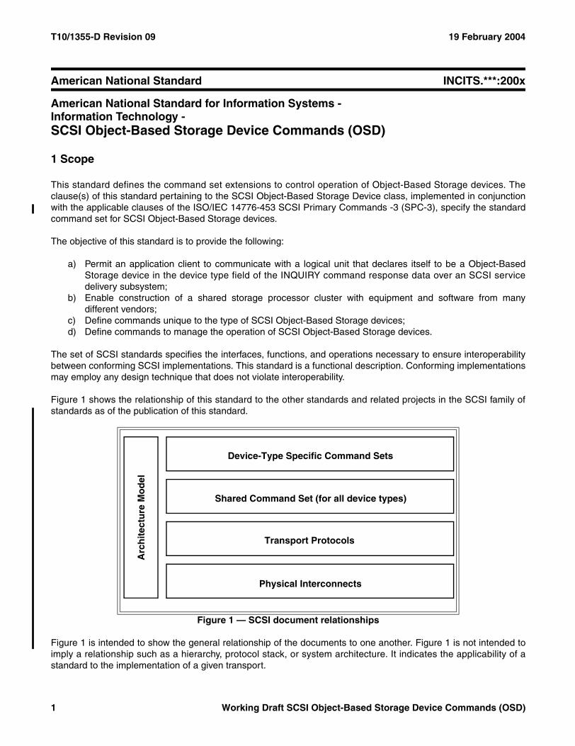
Figure 1 shows the relationship of this standard to the other standards and related projects in the SCSI family ofstandards as of the publication of this standard.
Figure 1 is intended to show the general relationship of the documents to one another. Figure 1 is not intended toimply a relationship such as a hierarchy, protocol stack, or system architecture. It indicates the applicability of astandard to the implementation of a given transport.
Figure 1 — SCSI document relationships
Arc
hit
ectu
re M
od
el
Physical Interconnects
Transport Protocols
Shared Command Set (for all device types)
Device-Type Specific Command Sets
1 Working Draft SCSI Object-Based Storage Device Commands (OSD)
19 February 2004 T10/1355-D Revision 09
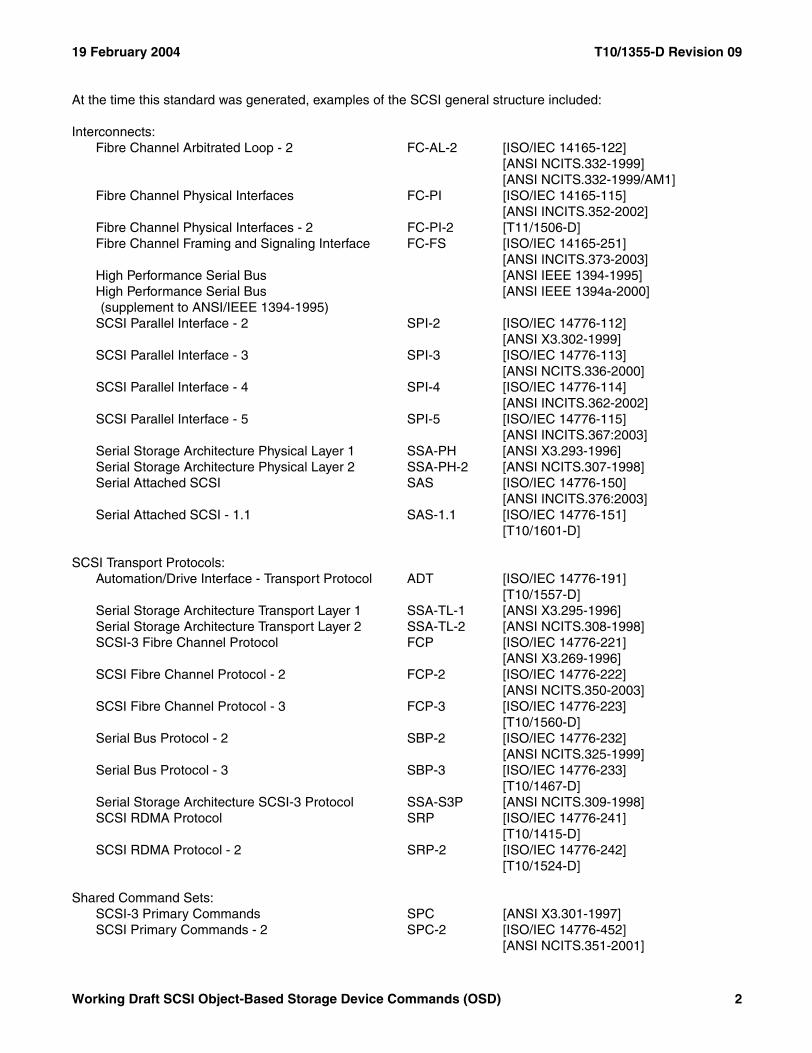
At the time this standard was generated, examples of the SCSI general structure included:
Interconnects:Fibre Channel Arbitrated Loop - 2 FC-AL-2 [ISO/IEC 14165-122]
[ANSI NCITS.332-1999][ANSI NCITS.332-1999/AM1]
Fibre Channel Physical Interfaces FC-PI [ISO/IEC 14165-115][ANSI INCITS.352-2002]
Fibre Channel Physical Interfaces - 2 FC-PI-2 [T11/1506-D]Fibre Channel Framing and Signaling Interface FC-FS [ISO/IEC 14165-251]
[ANSI INCITS.373-2003]High Performance Serial Bus [ANSI IEEE 1394-1995]High Performance Serial Bus [ANSI IEEE 1394a-2000](supplement to ANSI/IEEE 1394-1995)
SCSI Parallel Interface - 2 SPI-2 [ISO/IEC 14776-112][ANSI X3.302-1999]
SCSI Parallel Interface - 3 SPI-3 [ISO/IEC 14776-113][ANSI NCITS.336-2000]
SCSI Parallel Interface - 4 SPI-4 [ISO/IEC 14776-114][ANSI INCITS.362-2002]
SCSI Parallel Interface - 5 SPI-5 [ISO/IEC 14776-115][ANSI INCITS.367:2003]
Serial Storage Architecture Physical Layer 1 SSA-PH [ANSI X3.293-1996]Serial Storage Architecture Physical Layer 2 SSA-PH-2 [ANSI NCITS.307-1998]Serial Attached SCSI SAS [ISO/IEC 14776-150]
[ANSI INCITS.376:2003]Serial Attached SCSI - 1.1 SAS-1.1 [ISO/IEC 14776-151]
[T10/1601-D]
SCSI Transport Protocols:Automation/Drive Interface - Transport Protocol ADT [ISO/IEC 14776-191]
[T10/1557-D]Serial Storage Architecture Transport Layer 1 SSA-TL-1 [ANSI X3.295-1996]Serial Storage Architecture Transport Layer 2 SSA-TL-2 [ANSI NCITS.308-1998]SCSI-3 Fibre Channel Protocol FCP [ISO/IEC 14776-221]
[ANSI X3.269-1996]SCSI Fibre Channel Protocol - 2 FCP-2 [ISO/IEC 14776-222]
[ANSI NCITS.350-2003]SCSI Fibre Channel Protocol - 3 FCP-3 [ISO/IEC 14776-223]
[T10/1560-D]Serial Bus Protocol - 2 SBP-2 [ISO/IEC 14776-232]
[ANSI NCITS.325-1999]Serial Bus Protocol - 3 SBP-3 [ISO/IEC 14776-233]
[T10/1467-D]Serial Storage Architecture SCSI-3 Protocol SSA-S3P [ANSI NCITS.309-1998]SCSI RDMA Protocol SRP [ISO/IEC 14776-241]
[T10/1415-D]SCSI RDMA Protocol - 2 SRP-2 [ISO/IEC 14776-242]
[T10/1524-D]
Shared Command Sets:SCSI-3 Primary Commands SPC [ANSI X3.301-1997]SCSI Primary Commands - 2 SPC-2 [ISO/IEC 14776-452]
[ANSI NCITS.351-2001]
Working Draft SCSI Object-Based Storage Device Commands (OSD) 2
T10/1355-D Revision 09 19 February 2004
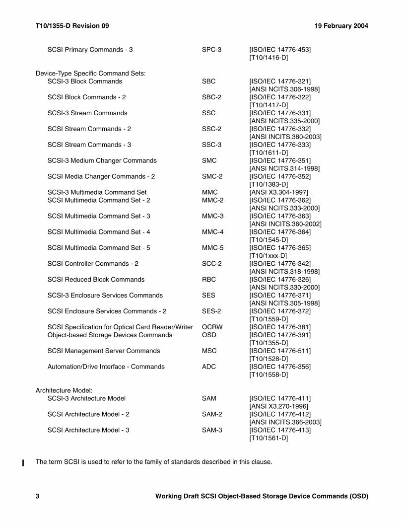
SCSI Primary Commands - 3 SPC-3 [ISO/IEC 14776-453][T10/1416-D]
Device-Type Specific Command Sets:SCSI-3 Block Commands SBC [ISO/IEC 14776-321]
[ANSI NCITS.306-1998]SCSI Block Commands - 2 SBC-2 [ISO/IEC 14776-322]
[T10/1417-D]SCSI-3 Stream Commands SSC [ISO/IEC 14776-331]
[ANSI NCITS.335-2000]SCSI Stream Commands - 2 SSC-2 [ISO/IEC 14776-332]
[ANSI INCITS.380-2003]SCSI Stream Commands - 3 SSC-3 [ISO/IEC 14776-333]
[T10/1611-D]SCSI-3 Medium Changer Commands SMC [ISO/IEC 14776-351]
[ANSI NCITS.314-1998]SCSI Media Changer Commands - 2 SMC-2 [ISO/IEC 14776-352]
[T10/1383-D]SCSI-3 Multimedia Command Set MMC [ANSI X3.304-1997]SCSI Multimedia Command Set - 2 MMC-2 [ISO/IEC 14776-362]
[ANSI NCITS.333-2000]SCSI Multimedia Command Set - 3 MMC-3 [ISO/IEC 14776-363]
[ANSI INCITS.360-2002]SCSI Multimedia Command Set - 4 MMC-4 [ISO/IEC 14776-364]
[T10/1545-D]SCSI Multimedia Command Set - 5 MMC-5 [ISO/IEC 14776-365]
[T10/1xxx-D]SCSI Controller Commands - 2 SCC-2 [ISO/IEC 14776-342]
[ANSI NCITS.318-1998]SCSI Reduced Block Commands RBC [ISO/IEC 14776-326]
[ANSI NCITS.330-2000]SCSI-3 Enclosure Services Commands SES [ISO/IEC 14776-371]
[ANSI NCITS.305-1998]SCSI Enclosure Services Commands - 2 SES-2 [ISO/IEC 14776-372]
[T10/1559-D]SCSI Specification for Optical Card Reader/Writer OCRW [ISO/IEC 14776-381]Object-based Storage Devices Commands OSD [ISO/IEC 14776-391]
[T10/1355-D]SCSI Management Server Commands MSC [ISO/IEC 14776-511]
[T10/1528-D]Automation/Drive Interface - Commands ADC [ISO/IEC 14776-356]
[T10/1558-D]
Architecture Model:SCSI-3 Architecture Model SAM [ISO/IEC 14776-411]
[ANSI X3.270-1996]SCSI Architecture Model - 2 SAM-2 [ISO/IEC 14776-412]
[ANSI INCITS.366-2003]SCSI Architecture Model - 3 SAM-3 [ISO/IEC 14776-413]
[T10/1561-D]
The term SCSI is used to refer to the family of standards described in this clause.
3 Working Draft SCSI Object-Based Storage Device Commands (OSD)
19 February 2004 T10/1355-D Revision 09
2 Normative references
2.1 Normative references
The standards identified in this subclause contain provisions that, by reference in the text, constitute provisions ofthis standard. At the time of publication, the editions indicated were valid. All standards are subject to revision, andparties to agreements based on this standard are encouraged to investigate the possibility of applying the mostrecent editions of the standards listed in this subclause.
2.2 Approved ISO references
Copies of the following documents may be obtained from ANSI:
a) Approved ANSI standards;b) Approved and draft international and regional standards (ISO, IEC, CEN/CENELEC, ITUT); andc) Approved and draft foreign standards (including BSI, JIS, and DIN).
For further information, contact ANSI Customer Service Department at 212-642-4900 (phone), 212-302-1286 (fax)or via the World Wide Web at http://www.ansi.org. In the event that the ANSI World Wide Web site is no longeractive, access may be possible via the INCITS World Wide Web site (http://www.incits.org), the IEC site (http://www.iec.ch/), the ISO site (http://www.iso.ch/), or the ISO/IEC JTC 1 web site (http://www.jtc1.org/).
ISO/IEC 14776-452, SCSI Primary Commands - 2 (SPC-2) [ANSI NCITS.351-2001]
2.3 Approved FIPS references
Copies of Federal Information Processing Standards (FIPS) document may be obtained via the World Wide Website (http://www.itl.nist.gov/fipspubs/). In the event that FIPS World Wide Web site is no longer active, access maybe possible via the Information Technology Laboratory World Wide Web site (http://www.itl.nist.gov/) or the NationalInstitute of Standards and Technology site (http://www.nist.gov/).
FIPS 180-1 (1995), Secure Hash Standard (i.e., SHA1)
FIPS 198 (2002), The Keyed-Hash Message Authentication Code (HMAC)
2.4 Approved IETF References
Copies of the following approved IETF standards may be obtained through the Internet Engineering Task Force(IETF) at www.ietf.org.
RFC 1750, Randomness Recommendations for Security
RFC 2401, Security Architecture for the Internet Protocol
Working Draft SCSI Object-Based Storage Device Commands (OSD) 4
T10/1355-D Revision 09 19 February 2004
2.5 References under development
At the time of publication, the following referenced standards were still under development by T10 (www.t10.org).For information on the current status of the document, or regarding availability, contact the T10 TechnicalCommittee or INCITS (www.incits.org).
ISO/IEC 14776-413, SCSI Architecture Model - 3 (SAM-3) [T10/1561-D]
ISO/IEC 14776-453, SCSI Primary Commands - 3 (SPC-3) [T10/1416-D]
5 Working Draft SCSI Object-Based Storage Device Commands (OSD)
19 February 2004 T10/1355-D Revision 09
3 Definitions, symbols, abbreviations, and conventions
3.1 Definitions
3.1.1 additional sense code: A combination of the ADDITIONAL SENSE CODE field and ADDITIONAL SENSE CODE
QUALIFIER field in the sense data (see 3.1.41).
3.1.2 application client: An object that is the source of SCSI commands. See SAM-3.
3.1.3 attributes: Data (sometimes called meta data) that is associated with an OSD object (see 3.1.27) that is notaccessible via read or write command functions (see 3.1.10). See 4.7.
3.1.4 capability: The fields in a credential (see 3.1.11) that are copied to a CDB to represent what commandfunctions (see 3.1.10) the command may request (e.g., what user object may be accessed). See 4.9.4.3.
3.1.5 capability key: The value in the CREDENTIAL INTEGRITY CHECK VALUE field (see 3.1.12) that is used by anapplication client to compute integrity check values for a single OSD command. See 4.9.4.2.
3.1.6 collection: An OSD object (see 3.1.27) in which references to one or more user objects from single partition(see 3.1.29) may be collected. See 4.6.6.
3.1.7 Collection_Object_ID: The identifier for one collection (see 3.1.6).
3.1.8 command: A request describing one or more command functions (see 3.1.10) to be performed by a deviceserver. See SAM-3.
3.1.9 command descriptor block (CDB): The structure used to communicate commands from an applicationclient to a device server. See SPC-3.
3.1.10 command function: One unit of work within a single command (see 3.1.8). This standard extends theSAM-3 definition of command to allow multiple command functions to be requested by a single command.
3.1.11 credential: A data structure prepared by the security manager (see 3.1.38) and protected by an integritycheck value (see 3.1.18) that is sent to an application client in order to grant defined access to an OSD logical unitfor specific command functions (see 3.1.10) performed on specific OSD objects. The credential includes acapability (see 3.1.4) that the application client copies to each CDB that requests the specified command functions.See 4.9.4.1.
3.1.12 credential integrity check value: The integrity check value (see 3.1.18) protecting a credential (see3.1.11). When the application client uses the credential integrity check value to compute integrity check values fora single OSD command, the value is called a capability key (see 3.1.5). See 4.9.4.1.
3.1.13 Data-In Buffer: The buffer identified by the application client to receive data from the device server duringthe processing of a command. See SAM-3.
3.1.14 Data-Out Buffer: The buffer identified by the application client to supply data that is sent from the appli-cation client to the device server during the processing of a command. See SAM-3.
3.1.15 device server: An object within a logical unit that processes SCSI tasks according to the rules of taskmanagement. See SAM-3.
3.1.16 field: A group of one or more contiguous bits, a part of a larger structure such as a CDB (see 3.1.9) orsense data (see 3.1.41).
Working Draft SCSI Object-Based Storage Device Commands (OSD) 6
T10/1355-D Revision 09 19 February 2004
3.1.17 I_T nexus: A nexus between a SCSI initiator port and a SCSI target port. See SAM-3.
3.1.18 integrity check value: A value computed using a security algorithm (e.g., HMAC-SHA1), a secret key (see3.1.37), and an array of bytes. See 4.9.7.
3.1.19 left-aligned: A type of field containing ASCII data in which unused bytes are placed at the end of the field(i.e., highest offset). See 3.7.1.
3.1.20 logical unit: An externally addressable entity within a SCSI device that implements a SCSI device modeland contains a device server. See SAM-3.
3.1.21 meta data: Information associated with an object that is not user data.
3.1.22 nexus: A relationship between two SCSI devices, and the SCSI initiator port and SCSI target port objectswithin those SCSI devices. See SAM-3.
3.1.23 nonce: A value that is used one and only one time and thus uniquely identifies a single instance ofsomething (e.g., an individual OSD command, or one credential) transacted between an application client, deviceserver, and security manager.
3.1.24 null-padded: A type of field in which unused bytes are filled with ASCII null (00h) characters. See 3.7.2.
3.1.25 object: 1: An ordered set of bytes within an object-based storage device that is associated with a uniqueidentifier. Data in the object is referenced by the identifier and offset information within the object. Objects areallocated and placed on the media by the OSD logical unit. 2: When used in relationship to SAM-3, a SCSI archi-tecture model object. See SAM-3.
3.1.26 object-based storage device (OBSD): A SCSI device that implements this standard in which data isorganized and accessed as objects.
3.1.27 OSD object: An object representing the root object (see 3.1.33), a partition (see 3.1.29), a collection (see3.1.6), or user object (see 3.1.48).
3.1.28 page: A regular parameter structure or format used by several commands. These pages are identified witha value known as a page code.
3.1.29 partition: An OSD object (see 3.1.27) used for creating distinct management domains (e.g., for naming,security, space allocation). See 4.6.3.
3.1.30 Partition_ID: The identifier for one partition (see 3.1.29).
3.1.31 partition zero: The partition with the Partition_ID (see 3.1.30) zero. The partition for the root object (see3.1.33).
3.1.32 request nonce: A nonce (see 3.1.23) having the format used by OSD command requests and responses.See 4.9.6.
3.1.33 root object: An OSD object (see 3.1.27) that is always present whose attributes contain global character-istics for the OSD logical unit. Each OSD logical unit has one and only one root object. See 4.6.1.
3.1.34 SCSI device: A device that contains one or more SCSI ports that are connected to a service deliverysubsystem and supports a SCSI application protocol. See SAM-3.
7 Working Draft SCSI Object-Based Storage Device Commands (OSD)
19 February 2004 T10/1355-D Revision 09
3.1.35 SCSI initiator port: A SCSI initiator device object that acts as the connection between application clientsand the service delivery subsystem through which requests and confirmations are routed. See SAM-3.
3.1.36 SCSI target port: A SCSI target device object that contains a task router and acts as the connectionbetween device servers and task managers and the service delivery subsystem through which indications andresponses are routed. See SAM-3.
3.1.37 secret key: A value that is known to only a limited set of at least two entities (e.g., the device server andsecurity manager) and serves as input for an integrity check value (see 3.1.18) computation.
3.1.38 security manager: The component of an OSD configuration (see 4.4) that manages secret keys (see3.1.37) and prepares credentials (see 3.1.11) granting application clients specified access to a specified OSDlogical unit.
3.1.39 security method: A set of zero or more security features and algorithms from the OSD security model thatare enabled as a group to thwart zero or more security threats. See 4.9.
3.1.40 security token: A value representing an I_T nexus (see 3.1.17) that both the application client and deviceserver are able to compute without any communications between them. See 4.9.3.2.
3.1.41 sense data: Data describing an error or exceptional condition that a device server delivers to an appli-cation client as described in SPC-3.
3.1.42 sense key: The contents of the SENSE KEY field in the sense data (see 3.1.41).
3.1.43 space-padded: A type of field in which unused bytes are filled with ASCII space (20h) characters. See3.7.2.
3.1.44 stable storage: Storage that survives all the events that may result in the lost of data in the volatile cache(see 3.1.51). See 4.10.
3.1.45 status: One byte of response information sent from a device server to an application client uponcompletion of each command. See SAM-3.
3.1.46 task: A SCSI architecture model object within a logical unit that represents the work associated with acommand or a group of linked commands. See SAM-3.
3.1.47 universal time (UT): The time at longitude zero, colloquially known as greenwich mean time. Seehttp://aa.usno.navy.mil/faq/docs/UT.html.
3.1.48 user object: An OSD object (see 3.1.27) that contains user data (see 4.6.1) that is referenced by byteoffset within the OSD object.
3.1.49 User_Object_ID: The identifier for one user object (see 4.6.1).
3.1.50 vendor specific: Something (e.g., a bit, field, code value, behavior) that is not defined by this standard andmay be vendor defined.
3.1.51 volatile cache: Storage Is lost after a power on or rest event (see SAM-3) and may be lost after an I_Tnexus loss or logical unit reset event (see SAM-3). See 4.10.
3.1.52 zero-padded: A type of field in which unused bytes are filled with zeros. See 3.7.2.
Working Draft SCSI Object-Based Storage Device Commands (OSD) 8
T10/1355-D Revision 09 19 February 2004
3.2 Acronyms
* arithmetic multiplicationC A constant equal to 6000 0000h used in describing object attribute page numbers (see 4.7.3)CDB Command Descriptor Block (see 3.1.9)FIPS Federal Information Processing Standard (see 2.3)HMAC-SHA1 Keyed-Hash Message Authentication Code - Secure Hash Standard 1 (see 2.3)I/O Input/OutputID IdentifierINCITS InterNational Committee for Information Technology StandardsISO Organization for International StandardsLSB Least Significant BitMSB Most Significant Bitn/a not applicableOBSD An Object-Based Storage Device, a SCSI device that implements this standard (see 3.1.26)OSD Object-based Storage Devices Commands (this standard, see clause 1)P A constant equal to 3000 0000h used in describing object attribute page numbers (see 4.7.3)R A constant equal to 9000 0000h used in describing object attribute page numbers (see 4.7.3)RAID Redundant Array of Independent DisksSAM-3 SCSI Architecture Model -3 (see clause 1)SAN Storage Area Network (see Storage Networking Industry Association web site, www.snia.org)SBC SCSI-3 Block Commands (see clause 1)SCSI The architecture defined by the family of standards described in clause 1SPC-2 SCSI Primary Commands -2 (see clause 1)SPC-3 SCSI Primary Commands -3 (see clause 1)UT Universal Time (see 3.1.47)VPD Vital Product Data (see SPC-3)
3.3 Keywords
3.3.1 expected: A keyword used to describe the behavior of the hardware or software in the design modelsassumed by this standard. Other hardware and software design models may also be implemented.
3.3.2 ignored: A keyword used to describe an unused bit, byte, word, field or code value. The contents or value ofan ignored bit, byte, word, field or code value shall not be examined by the receiving SCSI device and may be set toany value by the transmitting SCSI device.
3.3.3 invalid: A keyword used to describe an illegal or unsupported bit, byte, word, field or code value. Receipt ofan invalid bit, byte, word, field or code value shall be reported as an error.
3.3.4 mandatory: A keyword indicating an item that is required to be implemented as defined in this standard.
3.3.5 may: A keyword that indicates flexibility of choice with no implied preference (equivalent to "may or maynot").
3.3.6 may not: A keyword that indicates flexibility of choice with no implied preference (equivalent to "may or maynot").
3.3.7 obsolete: A keyword indicating that an item was defined in prior SCSI standards but has been removed fromthis standard.
9 Working Draft SCSI Object-Based Storage Device Commands (OSD)
19 February 2004 T10/1355-D Revision 09
3.3.8 optional: A keyword that describes features that are not required to be implemented by this standard.However, if any optional feature defined by this standards is implemented, then it shall be implemented as definedin this standard.
3.3.9 reserved: A keyword referring to bits, bytes, words, fields and code values that are set aside for futurestandardization. A reserved bit, byte, word or field shall be set to zero, or in accordance with a future extension tothis standard. Recipients are not required to check reserved bits, bytes, words or fields for zero values. Receipt ofreserved code values in defined fields shall be reported as error.
3.3.10 restricted: A keyword referring to bits, bytes, words, and fields that are set aside for use in other SCSIstandards. A restricted bit, byte, word, or field shall be treated as a reserved bit, byte, word or field for the purposesof the requirements defined in this standard.
3.3.11 shall: A keyword indicating a mandatory requirement. Designers are required to implement all suchmandatory requirements to ensure interoperability with other products that conform to this standard.
3.3.12 should: A keyword indicating flexibility of choice with a strongly preferred alternative; equivalent to thephrase "it is strongly recommended".
3.3.13 x or xx: The value of the bit or field is not relevant.
3.4 Conventions
Certain words and terms used in this standard have a specific meaning beyond the normal English meaning.These words and terms are defined either in 3.1 or in the text where they first appear. Names of commands,statuses, sense keys, and additional sense codes are in all uppercase (e.g., IDENTIFY DEVICE). Lowercase isused for words having the normal English meaning.
The names of fields are in small uppercase (e.g., STARTING BYTE ADDRESS). Normal case is used when the contentsof a field are being discussed. Fields containing only one bit are usually referred to as the NAME bit instead of theNAME field.
The most significant bit of a binary quantity is shown on the left side and represents the highest algebraic valueposition in the quantity.
Numbers that are not immediately followed by lower-case b or h are decimal values.
Numbers immediately followed by lower-case b (xxb) are binary values.
Numbers or upper case letters immediately followed by lower-case h (xxh) are hexadecimal values.
When the value of the bit or field is not relevant, x or xx appears in place of a specific value.
Lists sequenced by letters (e.g., a-red, b-blue, c-green) show no priority relationship between the listed items.Numbered lists (e.g., 1-red, 2-blue, 3-green) show a priority ordering between the listed items.
If a conflict arises between text, tables, or figures, the order of precedence to resolve the conflicts is text; thentables; and finally figures. Not all tables or figures are fully described in the text. Tables show data format andvalues. Notes do not constitute any requirements for implementors.
The ISO/IEC convention of numbering is used (i.e., the thousands and higher multiples are separated by a spaceand a comma is used as the decimal point as in 65 536 or 0,5).
Working Draft SCSI Object-Based Storage Device Commands (OSD) 10
T10/1355-D Revision 09 19 February 2004
3.5 Bit and byte ordering
This subclause describes the representation of fields in a table that defines the format of a SCSI structure (e.g., theformat of a CDB).
If a field consists of more than one bit and contains a single value (e.g., a number), the least significant bit (LSB) isshown on the right and the most significant bit (MSB) is shown on the left (e.g., in a byte, bit 7 is the MSB and isshown on the left; and bit 0 is the LSB and is shown on the right). The MSB and LSB are not labeled if the fieldconsists of 8 or fewer bits.
If a field consists of more than one byte and contains a single value, the byte containing the MSB is stored at thelowest address and the byte containing the LSB is stored at the highest address (i.e., big-endian byte ordering).The MSB and LSB are labeled.
If a field consists of more than one byte and contains multiple fields each with their own values (e.g., a descriptor),there is no MSB and LSB of the field itself and thus there are no MSB and LSB labels. Each individual field has anMSB and LSB that are labeled as appropriate in the table (if any) that describes the format of the sub-structurehaving multiple fields.
If a field contains a text string (e.g., ASCII), the MSB label is the MSB of the first character and the LSB label is theLSB of the last character.
When required for clarity, multiple byte fields may be represented with only two rows in a table. This condition isrepresented by values in the byte number column not increasing by one in each subsequent table row, thusindicating the presence of additional bytes.
3.6 Notation conventions
3.6.1 Notation for byte encoded character strings
When this standard requires one or more bytes to contain specific encoded character, the specific characters areenclosed in double quotation marks. The double quotation marks identify the start and end of the characters thatare required to be encoded but are not themselves to encoded. The characters that are to be encoded are shownin exactly the case that is to be encoded.
The encoded characters and the double quotation marks that enclose them are preceded by text that specifies thecharacter encoding methodology and the number of characters required to be encoded.
Using the notation described in this subclause, stating that eleven ASCII characters "SCSI device" are to beencoded would be the same writing out the following sequence of byte values: 53h 43h 53h 49h 20h 64h 65h 76h69h 63h 65h.
11 Working Draft SCSI Object-Based Storage Device Commands (OSD)
19 February 2004 T10/1355-D Revision 09
3.6.2 Notation for procedure calls
In this standard, the model for functional interfaces between objects is a procedure call. Such interfaces arespecified using the following notation:
[Result =] Procedure Name (IN ([input-1] [,input-2] …]), OUT ([output-1] [,output-2] …))
Where:
Result: A single value representing the outcome of the procedure call.
Procedure Name: A descriptive name for the function modeled by the procedure call. When the procedure call model is used to describe a SCSI transport protocol service, the procedure name is the same as the service name.
Input-1, Input-2, …: A comma-separated list of names identifying caller-supplied input arguments.
Output-1, Output-2, …: A comma-separated list of names identifying output arguments to be returned by the procedure call.
[ …]: Brackets enclosing optional or conditional arguments.
This notation allows arguments to be specified as inputs and outputs. The following is an example of a procedurecall specification:
Found = Search (IN (Pattern, Item List), OUT ([Item Found]))
Where:
Found = FlagFlag: if set to one, indicates that a matching item was located.
Input Arguments:
Pattern = … /* Definition of Pattern argument */Argument containing the search pattern.
Item List = Item<NN> /* Definition of Item List as an array of NN Item arguments*/Contains the items to be searched for a match.
Output Arguments:
Item Found = Item … /* Item located by the search procedure call */This argument is only returned if the search succeeds.
Working Draft SCSI Object-Based Storage Device Commands (OSD) 12
T10/1355-D Revision 09 19 February 2004
3.7 Data field requirements
3.7.1 ASCII data field requirements
ASCII data fields shall contain only ASCII graphic codes (i.e., code values 20h through 7Eh).
3.7.2 Data field termination and padding requirements
A data field that is described as being null-terminated shall have one byte containing an ASCII null (00h) characterin the last used byte (i.e., highest offset) of the field and all other bytes in the field shall not contain the ASCII nullcharacter.
A data field may be specified to be a fixed length that may be larger than the contents need or a data field may bespecified to have a length that is a multiple of a given value (e.g., a multiple of four bytes).
When such fields are described as being space-padded, the bytes at the end of the field that are not needed tocontain the field data shall contain ASCII space (20h) characters.
When such fields are described as being null-padded, the bytes at the end of the field that are not needed tocontain the field data shall contain ASCII null (00h) characters.
When such fields are described as being zero-padded, the bytes at the end of the field that are not needed tocontain the field data shall contain zeros.
NOTE 1 - There is no difference between the pad byte contents in null-padded and zero-padded fields. Thedifference is in the format of the other bytes in the field.
A data field that is described as being both null-terminated and null-padded shall have at least one byte containingan ASCII null (00h) character in the end of the field (i.e., highest offset) and may have more than one bytecontaining ASCII null characters if needed to meet the specified field length requirements. If more than one byte ina null-terminated, null-padded field contains the ASCII null character, all the bytes containing the ASCII nullcharacter shall be at the end of the field (i.e., only the highest offsets).
13 Working Draft SCSI Object-Based Storage Device Commands (OSD)
19 February 2004 T10/1355-D Revision 09
4 SCSI OSD Model
4.1 The request-response model
The SCSI command set assumes an underlying request-response protocol. The fundamental properties of therequest-response protocol are defined in SAM-3. Action on OSD commands shall not be deemed completed until aresponse is received. The response shall include a status that indicates the final disposition of the command. Asper SAM-3, the request-response protocol may be modeled as a procedure call, specifically:
Service response = Execute Command (IN (I_T_L_x Nexus, CDB, Task Attribute, [Data-In Buffer Size], [Data-Out Buffer], [Data-Out Buffer Size], [Command Reference Number]), OUT ([Data-In Buffer], [Sense Data], [Sense Data Length], Status))
SAM-3 defines all of the inputs and outputs in the procedure call above. As they apply to an OBSD (see 3.1.26),this standard defines the contents of the following procedure inputs and outputs; CDB, Data-Out Buffer, Data-OutBuffer Size, Data-In Buffer, Data-In Buffer Size, and Sense Data. This standard does not define all possibleinstances of these procedure inputs and outputs. This standard defines only those instances that apply to anOBSD.
This standard references values returned via the Status output parameter. Examples of such status values areGOOD and CHECK CONDITION. Status values are not defined by this standard. SAM-3 defines all Status values.
The entity that makes the procedure call via a SCSI initiator port is an application client, as defined in SAM-3. Theprocedure call's representation arrives at the SCSI target port in the form of a device service request. The entitythat performs the work of the procedure call is a device server, an object within a logical unit as defined in SAM-3.
4.2 OSD type devices
An OBSD (see 3.1.26) is a logical unit that returns the OSD peripheral device type value in response to anINQUIRY command (see SPC-3). From the perspective of the application client, an OBSD contains OSD objects(see 3.1.27), not logical blocks (see 4.5). All stored data objects (see 4.6) have attributes (see 4.7) associated withthem.
Working Draft SCSI Object-Based Storage Device Commands (OSD) 14
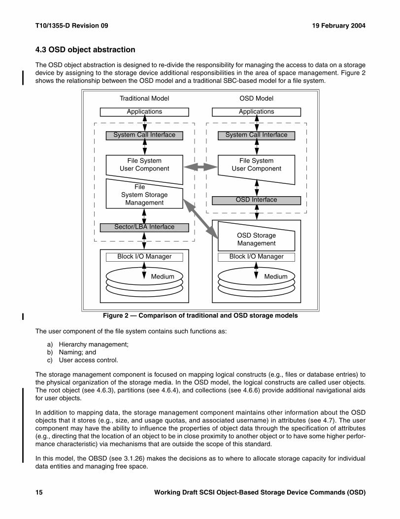
T10/1355-D Revision 09 19 February 2004
4.3 OSD object abstraction
The OSD object abstraction is designed to re-divide the responsibility for managing the access to data on a storagedevice by assigning to the storage device additional responsibilities in the area of space management. Figure 2shows the relationship between the OSD model and a traditional SBC-based model for a file system.
The user component of the file system contains such functions as:
a) Hierarchy management;b) Naming; andc) User access control.
The storage management component is focused on mapping logical constructs (e.g., files or database entries) tothe physical organization of the storage media. In the OSD model, the logical constructs are called user objects.The root object (see 4.6.3), partitions (see 4.6.4), and collections (see 4.6.6) provide additional navigational aidsfor user objects.
In addition to mapping data, the storage management component maintains other information about the OSDobjects that it stores (e.g., size, and usage quotas, and associated username) in attributes (see 4.7). The usercomponent may have the ability to influence the properties of object data through the specification of attributes(e.g., directing that the location of an object to be in close proximity to another object or to have some higher perfor-mance characteristic) via mechanisms that are outside the scope of this standard.
In this model, the OBSD (see 3.1.26) makes the decisions as to where to allocate storage capacity for individualdata entities and managing free space.
Figure 2 — Comparison of traditional and OSD storage models
Applications
Traditional Model OSD Model
Applications
System Call Interface System Call Interface
File SystemUser Component
FileSystem Storage
Management
File SystemUser Component
Sector/LBA Interface
Block I/O Manager Block I/O Manager
OSD Storage Management
OSD Interface
Medium Medium
15 Working Draft SCSI Object-Based Storage Device Commands (OSD)
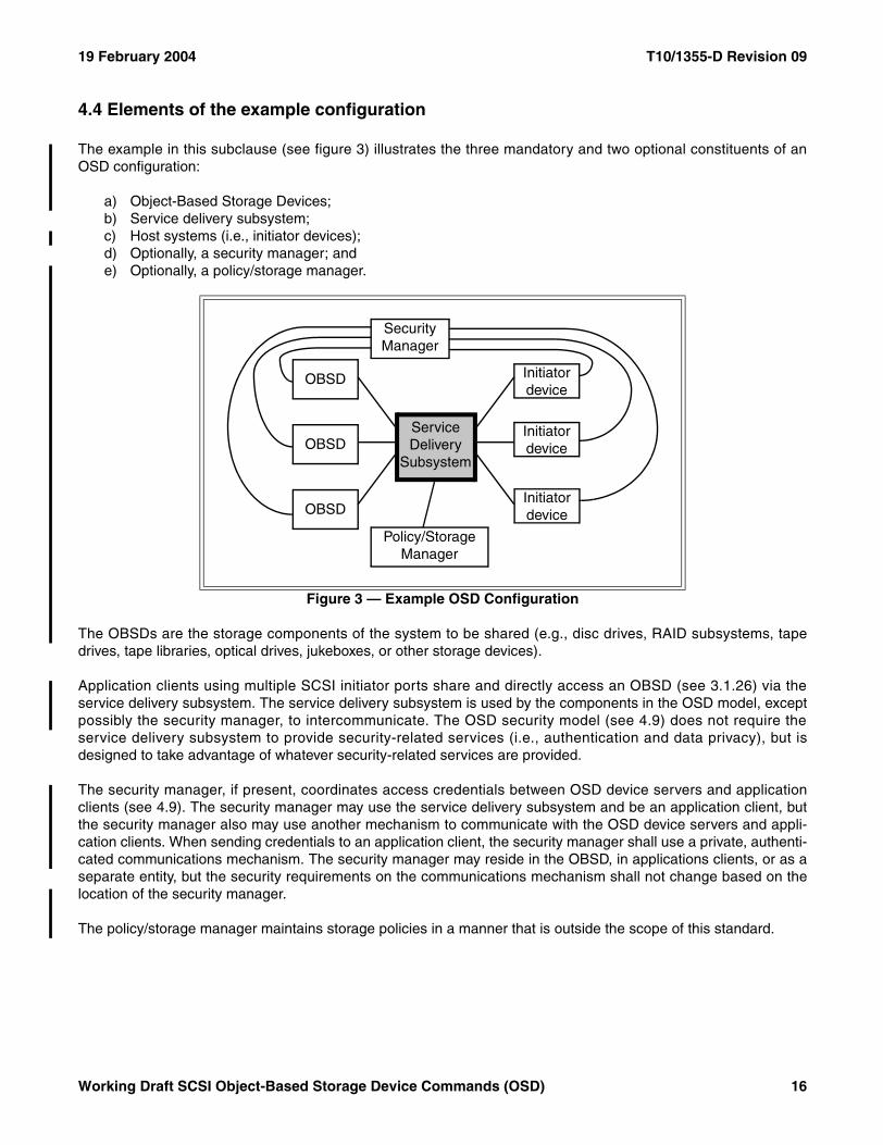
19 February 2004 T10/1355-D Revision 09
4.4 Elements of the example configuration
The example in this subclause (see figure 3) illustrates the three mandatory and two optional constituents of anOSD configuration:
a) Object-Based Storage Devices;b) Service delivery subsystem;c) Host systems (i.e., initiator devices);d) Optionally, a security manager; ande) Optionally, a policy/storage manager.
The OBSDs are the storage components of the system to be shared (e.g., disc drives, RAID subsystems, tapedrives, tape libraries, optical drives, jukeboxes, or other storage devices).
Application clients using multiple SCSI initiator ports share and directly access an OBSD (see 3.1.26) via theservice delivery subsystem. The service delivery subsystem is used by the components in the OSD model, exceptpossibly the security manager, to intercommunicate. The OSD security model (see 4.9) does not require theservice delivery subsystem to provide security-related services (i.e., authentication and data privacy), but isdesigned to take advantage of whatever security-related services are provided.
The security manager, if present, coordinates access credentials between OSD device servers and applicationclients (see 4.9). The security manager may use the service delivery subsystem and be an application client, butthe security manager also may use another mechanism to communicate with the OSD device servers and appli-cation clients. When sending credentials to an application client, the security manager shall use a private, authenti-cated communications mechanism. The security manager may reside in the OBSD, in applications clients, or as aseparate entity, but the security requirements on the communications mechanism shall not change based on thelocation of the security manager.
The policy/storage manager maintains storage policies in a manner that is outside the scope of this standard.
Figure 3 — Example OSD Configuration
Initiator device
OBSD
OBSD
OBSD
Policy/Storage Manager
Service Delivery
Subsystem
Security Manager
Initiator device
Initiator device
Working Draft SCSI Object-Based Storage Device Commands (OSD) 16
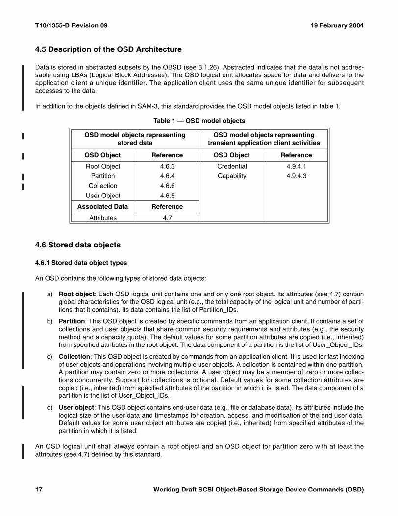
T10/1355-D Revision 09 19 February 2004
4.5 Description of the OSD Architecture
Data is stored in abstracted subsets by the OBSD (see 3.1.26). Abstracted indicates that the data is not addres-sable using LBAs (Logical Block Addresses). The OSD logical unit allocates space for data and delivers to theapplication client a unique identifier. The application client uses the same unique identifier for subsequentaccesses to the data.
In addition to the objects defined in SAM-3, this standard provides the OSD model objects listed in table 1.
4.6 Stored data objects
4.6.1 Stored data object types
An OSD contains the following types of stored data objects:
a) Root object: Each OSD logical unit contains one and only one root object. Its attributes (see 4.7) containglobal characteristics for the OSD logical unit (e.g., the total capacity of the logical unit and number of parti-tions that it contains). Its data contains the list of Partition_IDs.
b) Partition: This OSD object is created by specific commands from an application client. It contains a set ofcollections and user objects that share common security requirements and attributes (e.g., the securitymethod and a capacity quota). The default values for some partition attributes are copied (i.e., inherited)from specified attributes in the root object. The data component of a partition is the list of User_Object_IDs.
c) Collection: This OSD object is created by commands from an application client. It is used for fast indexingof user objects and operations involving multiple user objects. A collection is contained within one partition.A partition may contain zero or more collections. A user object may be a member of zero or more collec-tions concurrently. Support for collections is optional. Default values for some collection attributes arecopied (i.e., inherited) from specified attributes of the partition in which it is listed. The data component of apartition is the list of User_Object_IDs.
d) User object: This OSD object contains end-user data (e.g., file or database data). Its attributes include thelogical size of the user data and timestamps for creation, access, and modification of the end user data.Default values for some user object attributes are copied (i.e., inherited) from specified attributes of thepartition in which it is listed.
An OSD logical unit shall always contain a root object and an OSD object for partition zero with at least theattributes (see 4.7) defined by this standard.
Table 1 — OSD model objects
OSD model objects representingstored data
OSD model objects representing transient application client activities
OSD Object Reference OSD Object Reference
Root Object 4.6.3 Credential 4.9.4.1
Partition 4.6.4 Capability 4.9.4.3
Collection 4.6.6
User Object 4.6.5
Associated Data Reference
Attributes 4.7
17 Working Draft SCSI Object-Based Storage Device Commands (OSD)
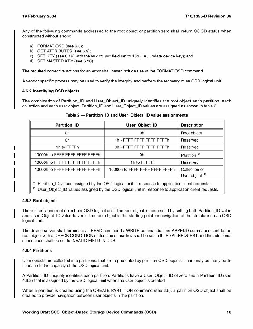
19 February 2004 T10/1355-D Revision 09
Any of the following commands addressed to the root object or partition zero shall return GOOD status whenconstructed without errors:
a) FORMAT OSD (see 6.8);b) GET ATTRIBUTES (see 6.9);c) SET KEY (see 6.19) with the KEY TO SET field set to 10b (i.e., update device key); andd) SET MASTER KEY (see 6.20).
The required corrective actions for an error shall never include use of the FORMAT OSD command.
A vendor specific process may be used to verify the integrity and perform the recovery of an OSD logical unit.
4.6.2 Identifying OSD objects
The combination of Partition_ID and User_Object_ID uniquely identifies the root object each partition, eachcollection and each user object. Partition_ID and User_Object_ID values are assigned as shown in table 2.
4.6.3 Root object
There is only one root object per OSD logical unit. The root object is addressed by setting both Partition_ID valueand User_Object_ID value to zero. The root object is the starting point for navigation of the structure on an OSDlogical unit.
The device server shall terminate all READ commands, WRITE commands, and APPEND commands sent to theroot object with a CHECK CONDITION status, the sense key shall be set to ILLEGAL REQUEST and the additionalsense code shall be set to INVALID FIELD IN CDB.
4.6.4 Partitions
User objects are collected into partitions, that are represented by partition OSD objects. There may be many parti-tions, up to the capacity of the OSD logical unit.
A Partition_ID uniquely identifies each partition. Partitions have a User_Object_ID of zero and a Partition_ID (see4.6.2) that is assigned by the OSD logical unit when the user object is created.
When a partition is created using the CREATE PARTITION command (see 6.5), a partition OSD object shall becreated to provide navigation between user objects in the partition.
Table 2 — Partition_ID and User_Object_ID value assignments
Partition_ID User_Object_ID Description
0h 0h Root object
0h 1h - FFFF FFFF FFFF FFFFh Reserved
1h to FFFFh 0h - FFFF FFFF FFFF FFFFh Reserved
10000h to FFFF FFFF FFFF FFFFh 0h Partition a
10000h to FFFF FFFF FFFF FFFFh 1h to FFFFh Reserved
10000h to FFFF FFFF FFFF FFFFh 10000h to FFFF FFFF FFFF FFFFh Collection or
User object b
a Partition_ID values assigned by the OSD logical unit in response to application client requests.b User_Object_ID values assigned by the OSD logical unit in response to application client requests.
Working Draft SCSI Object-Based Storage Device Commands (OSD) 18
T10/1355-D Revision 09 19 February 2004
To obtain a list of the valid Partition_IDs, an application client sends the LIST command (see 6.10) to the deviceserver specifying the root object.
The device server shall terminate all READ commands, WRITE commands, and APPEND commands sent to apartition with a CHECK CONDITION status, the sense key shall be set to ILLEGAL REQUEST and the additionalsense code shall be set to INVALID FIELD IN CDB.
4.6.5 User objects
User objects contain end-user data (i.e., the content of this data is owned by the applications that cause thecreation, writing and reading the user objects). User objects have the Partition_ID of the partition to which theybelong and a User_Object_ID (see 4.6.2) that is assigned by the OSD logical unit when the user object is created.A user object is a member of only one partition.
Within a single par tit ion, no user object shall be assigned the same User_Object_ID value as anyCollection_Object_ID and no collection shall be assigned the same Collection_Object_ID as any User_Object_ID(i.e., collections and user objects share the same number space for their identifier values).
A user object may be made a member of one or more collections (see 4.6.6) by setting attribute values in the userobject’s Collections attributes page (see 7.1.2.19).
4.6.6 Collections
Support for collections is optional.
A partition may contain zero or more collections each of which may contain zero or more user objects. One userobject may be a member of zero or more collections. User objects are added to or removed from the membershipof a collection by setting attribute values in the user object’s Collections attributes page (see 7.1.2.19).
Collections have the Partition_ID of the partition to which they belong and a Collection_Object_ID (see 4.6.2) thatis assigned by the OSD logical unit when the collection is created. A collection is a member of only one partition.
Within a single par tit ion, no user object shall be assigned the same User_Object_ID value as anyCollection_Object_ID and no collection shall be assigned the same Collection_Object_ID as any User_Object_ID(i.e., collections and user objects share the same number space for their identifier values).
A collection is created using the CREATE COLLECTION command (see 6.5) and deleted using the REMOVECOLLECTION command (see 6.16). The page format of the Collections attributes page (see 7.1.2.19) lists all thecollections in which a user object is a member. The LIST COLLECTION command (see 6.11) lists all the collec-tions in a partition or all the user objects that are members of a collection.
The device server shall terminate all READ commands, WRITE commands, and APPEND commands sent to thecollection with a CHECK CONDITION status, the sense key shall be set to ILLEGAL REQUEST and the additionalsense code shall be set to INVALID FIELD IN CDB.
19 Working Draft SCSI Object-Based Storage Device Commands (OSD)
19 February 2004 T10/1355-D Revision 09
4.7 OSD object attributes
4.7.1 Overview
File systems and other SBC-based systems store both user data and meta data. OSD object attributes allow theassociation of meta data with any OSD object (i.e., root, partition, collection, or user). Attributes may be used todescribe specific characteristics of an OSD object (e.g., the total amount of bytes occupied by the OSD object(including attributes), logical size of the OSD object, and the time the OSD object was last modified).
Any OSD command may retrieve attributes and any OSD command may store attributes.
The GET ATTRIBUTES command (see 6.9) and SET ATTRIBUTES command (see 6.18) allow attributes to beretrieved and store without performing other command functions (see 3.1.10).
An OSD command may only retrieve or set attributes in the attributes pages associated with the OSD objectaddressed by the command.
Attributes are organized in pages for identification and reference. The attributes within a page have similar sourcesor uses. Within each attributes page, attributes are identified by an attribute number. Each attributes page isassociated with one of the following:
a) The root object;b) A partition;c) A collection;d) A user object;e) All OSD object types.
With the exception of attributes pages in the attributes page number range assigned to all OSD object types (seetable 3 in 4.7.3), the same attributes page shall not be associated with more than one OSD object.
The structures of attributes pages are defined by standards (e.g., this standard, other American NationalStandards, ISO standards), by OSD applications specifications (e.g., SAN file systems, data base systems, fixeddata repositories), by publicly available manufacturer product specifications, and by other written documentation. Arange of vendor specific attributes pages is defined for which the usage is not restricted by this standard.
4.7.2 Command function ordering for commands that get and/or set attributes
OSD commands provide the application client with the optional ability to get and set attributes as part of processingthe command (e.g., a WRITE command may also retrieve the user object logical length attribute). This subclausedefines the relative order of the command functions (see 3.1.10) processing within a single command.
The processing of commands other than GET ATTRIBUTES, SET ATTRIBUTES, REMOVE, REMOVEPARTITION, and REMOVE COLLECTION that include getting or setting attributes shall be performed in thefollowing order:
1) Processing those command functions not related to attributes (e.g., writing data to a user object);2) Process any set attributes command functions resulting from the processing of the command (e.g.,
changes due to a WRITE command); and3) Process any set attributes command functions specified in the CDB;4) Process any get attributes command functions specified in the CDB.
Working Draft SCSI Object-Based Storage Device Commands (OSD) 20
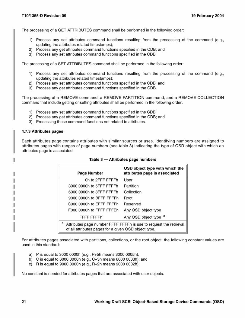
T10/1355-D Revision 09 19 February 2004
The processing of a GET ATTRIBUTES command shall be performed in the following order:
1) Process any set attributes command functions resulting from the processing of the command (e.g.,updating the attributes related timestamps);
2) Process any get attributes command functions specified in the CDB; and3) Process any set attributes command functions specified in the CDB.
The processing of a SET ATTRIBUTES command shall be performed in the following order:
1) Process any set attributes command functions resulting from the processing of the command (e.g.,updating the attributes related timestamps);
2) Process any set attributes command functions specified in the CDB; and3) Process any get attributes command functions specified in the CDB.
The processing of a REMOVE command, a REMOVE PARTITION command, and a REMOVE COLLECTIONcommand that include getting or setting attributes shall be performed in the following order:
1) Process any set attributes command functions specified in the CDB;2) Process any get attributes command functions specified in the CDB; and3) Processing those command functions not related to attributes.
4.7.3 Attributes pages
Each attributes page contains attributes with similar sources or uses. Identifying numbers are assigned toattributes pages with ranges of page numbers (see table 3) indicating the type of OSD object with which anattributes page is associated.
For attributes pages associated with partitions, collections, or the root object, the following constant values areused in this standard:
a) P is equal to 3000 0000h (e.g., P+5h means 3000 0005h);b) C is equal to 6000 0000h (e.g., C+3h means 6000 0003h); andc) R is equal to 9000 0000h (e.g., R+2h means 9000 0002h).
No constant is needed for attributes pages that are associated with user objects.
Table 3 — Attributes page numbers
Page NumberOSD object type with which the attributes page is associated
0h to 2FFF FFFFh User
3000 0000h to 5FFF FFFFh Partition
6000 0000h to 8FFF FFFFh Collection
9000 0000h to BFFF FFFFh Root
C000 0000h to EFFF FFFFh Reserved
F000 0000h to FFFF FFFEh Any OSD object type
FFFF FFFFh Any OSD object type a
a Attributes page number FFFF FFFFh is use to request the retrieval of all attributes pages for a given OSD object type.
21 Working Draft SCSI Object-Based Storage Device Commands (OSD)
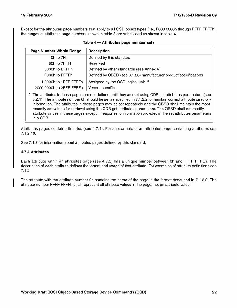
19 February 2004 T10/1355-D Revision 09
Except for the attributes page numbers that apply to all OSD object types (i.e., F000 0000h through FFFF FFFFh),the ranges of attributes page numbers shown in table 3 are subdivided as shown in table 4.
Attributes pages contain attributes (see 4.7.4). For an example of an attributes page containing attributes see7.1.2.16.
See 7.1.2 for information about attributes pages defined by this standard.
4.7.4 Attributes
Each attribute within an attributes page (see 4.7.3) has a unique number between 0h and FFFF FFFEh. Thedescription of each attribute defines the format and usage of that attribute. For examples of attribute definitions see7.1.2.
The attribute with the attribute number 0h contains the name of the page in the format described in 7.1.2.2. Theattribute number FFFF FFFFh shall represent all attribute values in the page, not an attribute value.
Table 4 — Attributes page number sets
Page Number Within Range Description
0h to 7Fh Defined by this standard
80h to 7FFFh Reserved
8000h to EFFFh Defined by other standards (see Annex A)
F000h to FFFFh Defined by OBSD (see 3.1.26) manufacturer product specifications
1 0000h to 1FFF FFFFh Assigned by the OSD logical unit a
2000 0000h to 2FFF FFFFh Vendor specifica The attributes in these pages are not defined until they are set using CDB set attributes parameters (see
5.2.1). The attribute number 0h should be set as specified in 7.1.2.2 to maintain correct attribute directory information. The attributes in these pages may be set repeatedly and the OBSD shall maintain the most recently set values for retrieval using the CDB get attributes parameters. The OBSD shall not modify attribute values in these pages except in response to information provided in the set attributes parameters in a CDB.
Working Draft SCSI Object-Based Storage Device Commands (OSD) 22
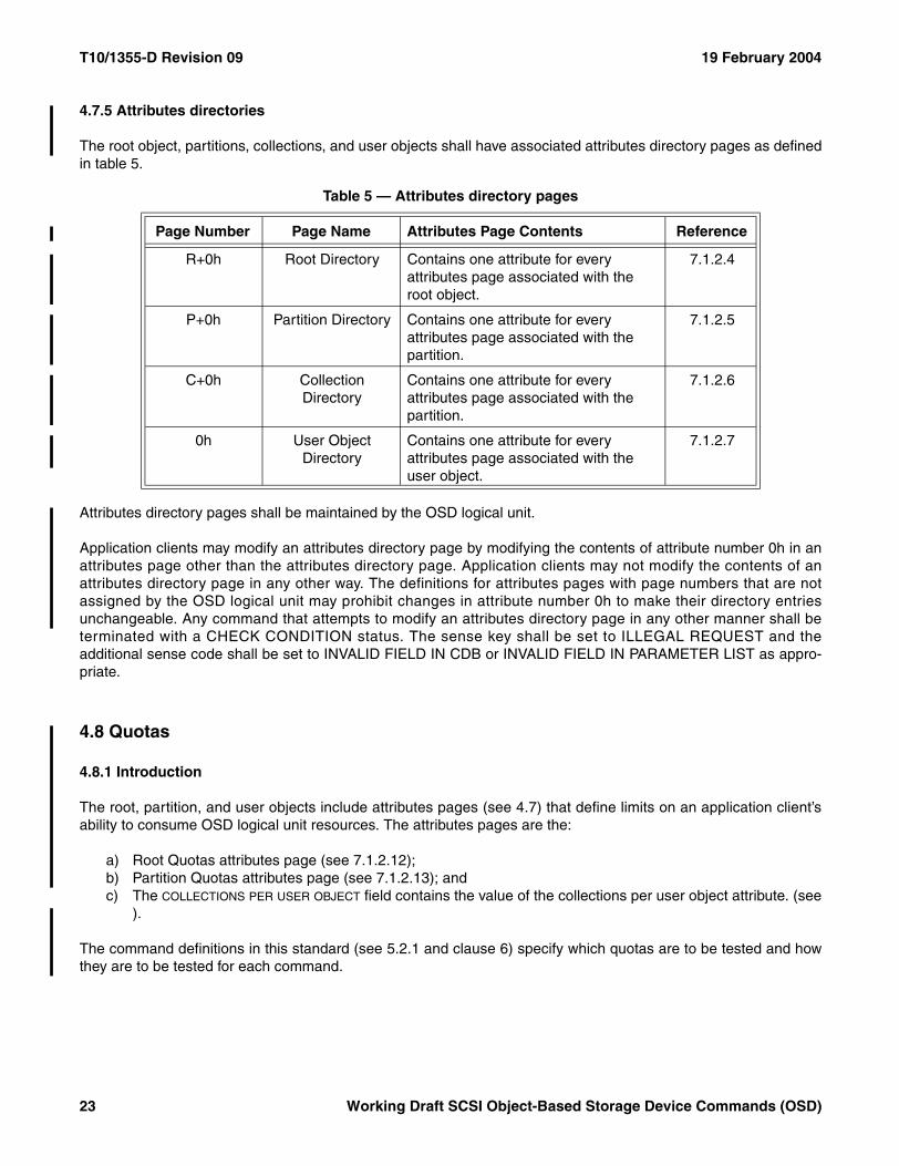
T10/1355-D Revision 09 19 February 2004
4.7.5 Attributes directories
The root object, partitions, collections, and user objects shall have associated attributes directory pages as definedin table 5.
Attributes directory pages shall be maintained by the OSD logical unit.
Application clients may modify an attributes directory page by modifying the contents of attribute number 0h in anattributes page other than the attributes directory page. Application clients may not modify the contents of anattributes directory page in any other way. The definitions for attributes pages with page numbers that are notassigned by the OSD logical unit may prohibit changes in attribute number 0h to make their directory entriesunchangeable. Any command that attempts to modify an attributes directory page in any other manner shall beterminated with a CHECK CONDITION status. The sense key shall be set to ILLEGAL REQUEST and theadditional sense code shall be set to INVALID FIELD IN CDB or INVALID FIELD IN PARAMETER LIST as appro-priate.
4.8 Quotas
4.8.1 Introduction
The root, partition, and user objects include attributes pages (see 4.7) that define limits on an application client’sability to consume OSD logical unit resources. The attributes pages are the:
a) Root Quotas attributes page (see 7.1.2.12);b) Partition Quotas attributes page (see 7.1.2.13); andc) The COLLECTIONS PER USER OBJECT field contains the value of the collections per user object attribute. (see
).
The command definitions in this standard (see 5.2.1 and clause 6) specify which quotas are to be tested and howthey are to be tested for each command.
Table 5 — Attributes directory pages
Page Number Page Name Attributes Page Contents Reference
R+0h Root Directory Contains one attribute for every attributes page associated with the root object.
7.1.2.4
P+0h Partition Directory Contains one attribute for every attributes page associated with the partition.
7.1.2.5
C+0h Collection Directory
Contains one attribute for every attributes page associated with the partition.
7.1.2.6
0h User Object Directory
Contains one attribute for every attributes page associated with the user object.
7.1.2.7
23 Working Draft SCSI Object-Based Storage Device Commands (OSD)
19 February 2004 T10/1355-D Revision 09
4.8.2 Quota errors
If one of the quota error conditions described in 5.2.1 and clause 6 occurs, processing of the command shall beterminated and a quota error shall be reported as follows:
a) The status shall be CHECK CONDITION;b) The sense key shall be DATA PROTECT;c) The additional sense code shall be QUOTA ERROR; andd) The sense data shall include the OSD attribute identification sense data descriptor (see SPC-3) with one
or more attribute descriptors identifying the quota attribute or attributes that have been exceeded.
4.8.3 Quota testing
Tests for quota errors may be made at any time during the processing of a command. The processing of acommand may be partially completed at the time a quota error is detected. The device server is not required torestore the state of the OSD logical unit to the state that was present before processing was begun for thecommand in which the quota error has been detected.
The device server may implement a vendor specific margin in the tests related to any quota and generate a quotaerror if a command attempts to consume resources within the margin adjusted quota limit. The size of the vendorspecific margin may vary over time in a vendor specific manner.
4.8.4 Changing quotas
The quota values are contained in attributes that may be set by command with an appropriate capability. Thedevice server may constrain the values to which a quota attribute may be set and return CHECK CONDITIONstatus if an attempt is made to set a quota to an unsupported value.
Setting a quota to a value that is less than the applicable resources already consumed in the OSD logical unit:
a) Shall not be an error; andb) Shall not result in the truncation or removal of any information (e.g., user data or attribute values) already
stored by the OSD logical unit.
As long as the quota value remains set to a value that is less than the applicable resources already consumed, allcommands that attempt to consume the applicable resource shall be terminated with a quota error.
4.9 Security
4.9.1 Basic security model
The OSD security model is a credential-based access control system composed of the following components:
a) An OBSD (see 3.1.26)b) A security manager; and c) Application clients.
Because the OSD security model is a credential-based access control system, all requests to the OSD logical unitshould be accompanied by a valid credential that allows the application client to perform the requested commandfunctions. A credential is a cryptographically secured capability and a capability is a set of access rights allowed tothe holder of the credential on an OSD object or set of OSD objects.
Working Draft SCSI Object-Based Storage Device Commands (OSD) 24
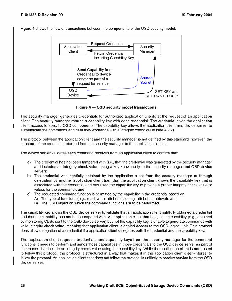
T10/1355-D Revision 09 19 February 2004
Figure 4 shows the flow of transactions between the components of the OSD security model.
The security manager generates credentials for authorized application clients at the request of an applicationclient. The security manager returns a capability key with each credential. The credential gives the applicationclient access to specific OSD components. The capability key allows the application client and device server toauthenticate the commands and data they exchange with a integrity check value (see 4.9.7).
The protocol between the application client and the security manager is not defined by this standard; however, thestructure of the credential returned from the security manager to the application client is.
The device server validates each command received from an application client to confirm that:
a) The credential has not been tampered with (i.e., that the credential was generated by the security managerand includes an integrity check value using a key known only to the security manager and OSD deviceserver);
b) The credential was rightfully obtained by the application client from the security manager or throughdelegation by another application client (i.e., that the application client knows the capability key that isassociated with the credential and has used the capability key to provide a proper integrity check value orvalues for the command); and
c) The requested command function is permitted by the capability in the credential based on:A) The type of functions (e.g., read, write, attributes setting, attributes retrieval); andB) The OSD object on which the command functions are to be performed.
The capability key allows the OSD device server to validate that an application client rightfully obtained a credentialand that the capability has not been tampered with. An application client that has just the capability (e.g., obtainedby monitoring CDBs sent to the OSD device server) but not the capability key is unable to generate commands withvalid integrity check value, meaning that application client is denied access to the OSD logical unit. This protocoldoes allow delegation of a credential if a application client delegates both the credential and the capability key.
The application client requests credentials and capability keys from the security manager for the commandfunctions it needs to perform and sends those capabilities in those credentials to the OSD device server as part ofcommands that include an integrity check value using the capability key. While the application client is not trustedto follow this protocol, the protocol is structured in a way that makes it in the application client’s self-interest tofollow the protocol. An application client that does not follow the protocol is unlikely to receive service from the OSDdevice server.
Figure 4 — OSD security model transactions
OSDDevice
Application Client
SecurityManager
Request Credential
Return Credential Including Capability Key
Send Capability from Credential to device server as part of a request for service
Shared Secret
SET KEY andSET MASTER KEY
25 Working Draft SCSI Object-Based Storage Device Commands (OSD)
19 February 2004 T10/1355-D Revision 09
The security manager may authenticate the application client, but the OSD device server does not need to authen-ticate the application client. It is sufficient for the OSD device server to verify the capabilities and integrity checkvalues send by the application client.
4.9.2 Trust assumptions
This subclause describes how each component of the OSD security model trusts the other components.
The OBSD is a trusted component, meaning that once an application client authenticates that it is communicatingwith a specific OSD logical unit using methods outside the scope of this standard, it trusts the OBSD to:
a) Provide integrity for stored data;b) Perform the security protocol and functions defined for it by this standard; andc) Not be controlled in a way that operates to the detriment of the application client’s interests.
The security manager is a trusted component. After the security manager is authenticated by the application clientand the OBSD using methods outside the scope of this standard, the security manager is trusted to:
a) Safely store long-lived keys;b) Apply access controls correctly according to requirements that are outside the scope of this standard;c) Perform the security functions defined for it by this standard; andd) Not be controlled in a way that operates to the detriment of the application client’s or OSD logical unit’s
interests.
The application client is not a trusted component. However, the OSD security model is defined so that the appli-cation client receives service from the OSD device server only if it interacts with both the security manager and theOSD device server in ways that assure the propriety of the application client’s actions.
4.9.3 Security methods
4.9.3.1 Introduction
This standard defines several security methods (see table 6).
The security method used by one partition may be different from the security method used by another partition.
A command prepared for a security mode other than the one the device server uses for processing may completewithout errors (e.g., a command prepared for the ALLDATA security method may complete without errors reportedby the device server if the CMDRSP security method is in use because the preparations for the ALLDATA securitymethod include the preparations that are necessary for the CMDRSP security method).
Table 6 — OSD security methods
Security Method Description Reference
NOSEC No security 4.9.3.2
CAPKEY Integrity of capabilities 4.9.3.3
CMDRSP Integrity of CDB, status, and sense data 4.9.3.4
ALLDATA Integrity of all data in transit 4.9.3.5
Working Draft SCSI Object-Based Storage Device Commands (OSD) 26
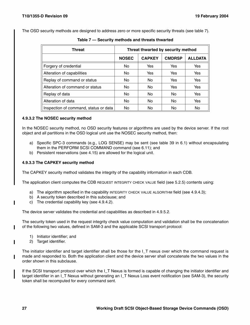
T10/1355-D Revision 09 19 February 2004
The OSD security methods are designed to address zero or more specific security threats (see table 7).
4.9.3.2 The NOSEC security method
In the NOSEC security method, no OSD security features or algorithms are used by the device server. If the rootobject and all partitions in the OSD logical unit use the NOSEC security method, then:
a) Specific SPC-3 commands (e.g., LOG SENSE) may be sent (see table 39 in 6.1) without encapsulatingthem in the PERFORM SCSI COMMAND command (see 6.11); and
b) Persistent reservations (see 4.15) are allowed for the logical unit.
4.9.3.3 The CAPKEY security method
The CAPKEY security method validates the integrity of the capability information in each CDB.
The application client computes the CDB REQUEST INTEGRITY CHECK VALUE field (see 5.2.5) contents using:
a) The algorithm specified in the capability INTEGRITY CHECK VALUE ALGORITHM field (see 4.9.4.3);b) A security token described in this subclause; andc) The credential capability key (see 4.9.4.2).
The device server validates the credential and capabilities as described in 4.9.5.2.
The security token used in the request integrity check value computation and validation shall be the concatenationof the following two values, defined in SAM-3 and the applicable SCSI transport protocol:
1) Initiator identifier; and2) Target identifier.
The initiator identifier and target identifier shall be those for the I_T nexus over which the command request ismade and responded to. Both the application client and the device server shall concatenate the two values in theorder shown in this subclause.
If the SCSI transport protocol over which the I_T Nexus is formed is capable of changing the initiator identifier andtarget identifier in an I_T Nexus without generating an I_T Nexus Loss event notification (see SAM-3), the securitytoken shall be recomputed for every command sent.
Table 7 — Security methods and threats thwarted
Threat Threat thwarted by security method
NOSEC CAPKEY CMDRSP ALLDATA
Forgery of credential No Yes Yes Yes
Alteration of capabilities No Yes Yes Yes
Replay of command or status No No Yes Yes
Alteration of command or status No No Yes Yes
Replay of data No No No Yes
Alteration of data No No No Yes
Inspection of command, status or data No No No No
27 Working Draft SCSI Object-Based Storage Device Commands (OSD)
19 February 2004 T10/1355-D Revision 09
If the application client and device server are in separate SCSI domains (e.g., connected by a bridging device, seeSAM-3) the security tokens built by the application client and device server have a high probability of beingdifferent, resulting in comparison failures of the request integrity check values. The credential should appear tohave been tampered with when this is not truly the case. The problems caused by multiple SCSI domains may besolved by using a different security method (e.g., the CMDRSP security method).
The CAPKEY security method is useful when the service delivery subsystem between the OSD device server andapplication client is secured via methods specified in the applicable SCSI transport protocol. Combining theCAPKEY security method with a secure transport (i.e., one that provides an authenticated channel) provides thesame as the ALLDATA security method. Even when communications are secured by such means, it is necessary toprevent the untrusted application client (see 4.9.2) from forging or otherwise modifying a credential.
4.9.3.4 The CMDRSP security method
The CMDRSP security method validates the integrity of the CDB, status, and sense data for each command.
The application client computes the CDB REQUEST INTEGRITY CHECK VALUE field (see 5.2.5) contents using:
a) The algorithm specified in the capability INTEGRITY CHECK VALUE ALGORITHM field (see 4.9.4.3);b) All the bytes in the CDB with the bytes in the REQUEST INTEGRITY CHECK VALUE field set to zero; andc) The credential capability key (see 4.9.4.2).
The device server validates the credential and capabilities as described in 4.9.5.2.
If the credential and capabilities validation process successfully validates the integrity check value associated withthe command, the device server shall:
1) Compute an integrity check value for the response data using:A) The algorithm specified in the capability INTEGRITY CHECK VALUE ALGORITHM field (see 4.9.4.3);B) The following array of bytes:
1) The request nonce from the CDB (see 5.2.5);2) The status byte; and 3) If the status is CHECK CONDITION, the sense data with the RESPONSE INTEGRITY CHECK VALUE
field in the OSD response integrity check value sense data descriptor (see SPC-3) set to zero;and
C) The capability key (see 4.9.4.2) for the reconstructed credential (see 4.9.5.3);and
2) Place the computed integrity check value in the following location:A) If the status is not CHECK CONDITION, the computed integrity check value shall be placed in the
response integrity check value attribute in the Current Command attributes page (see 7.1.2.24); orB) If the status is CHECK CONDITION, the computed integrity check value shall be placed in the
RESPONSE INTEGRITY CHECK VALUE field in the OSD response integrity check value sense datadescriptor in the sense data.
If the credential and capabilities validation process fails to validate the integrity check value associated with thecommand, the device server shall place zero in the RESPONSE INTEGRITY CHECK VALUE field in the OSD responseintegrity check value sense data descriptor in the sense data.
If the status is not CHECK CONDITION, the application client validates the response integrity check value byrecomputing it as described in this subclause and comparing the result to the value of the response integrity checkvalue attribute in the Current Command attributes page.
Working Draft SCSI Object-Based Storage Device Commands (OSD) 28
T10/1355-D Revision 09 19 February 2004
If the status is CHECK CONDITION, the application client validates the response integrity check value by:
1) Saving the response integrity check value found in the RESPONSE INTEGRITY CHECK VALUE field in the OSDresponse integrity check value sense data descriptor in the sense data;
2) Placing zero in the response integrity check value found in the RESPONSE INTEGRITY CHECK VALUE field inthe OSD response integrity check value sense data descriptor;
3) Recomputing the response integrity check value as described in this subclause; and4) Comparing the result to the value saved in step 1).
If the application client fails in validating the response integrity check value as described in this subclause, it shouldtake a recovery action not specified by this standard. One possible action is to request a new credential from thesecurity manager and retry the command. If the error reoccurs, alternate recovery actions should be consideredand the presence of malicious entities perpetrating a denial of service attack should be considered.
The CMDRSP security method may be used when the service delivery subsystem between the OSD device serverand application client is not secured. The CMDRSP security method protects against corruption of the commandand CDB parameters while avoiding the overhead that may be required to protect all transferred data. Use of theCMDRSP security method prevents an untrusted application client from forging, modifying or replaying a capability.
4.9.3.5 The ALLDATA security method
The ALLDATA security method validates the integrity of all data in transit between an application client and deviceserver.
The application client computes the CDB REQUEST INTEGRITY CHECK VALUE field (see 5.2.5) contents using thesame algorithm specified for the CMDRSP security method (see 4.9.3.4). The device server validates thecredential and capabilities as described in 4.9.5.2.
The application client also computes the data-out integrity check value using:
a) The algorithm specified in the capability INTEGRITY CHECK VALUE ALGORITHM field (see 4.9.4.3);b) The used bytes in the following Data-Out Buffer segments (see 4.11.3);
1) Command data or parameter data;2) Set attributes; and3) Get attributes;and
c) The credential capability key (see 4.9.4.2).
29 Working Draft SCSI Object-Based Storage Device Commands (OSD)
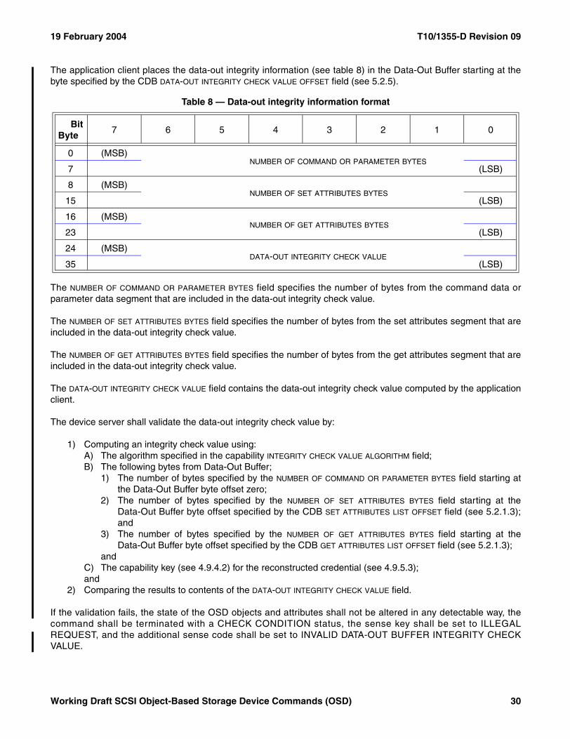
19 February 2004 T10/1355-D Revision 09
The application client places the data-out integrity information (see table 8) in the Data-Out Buffer starting at thebyte specified by the CDB DATA-OUT INTEGRITY CHECK VALUE OFFSET field (see 5.2.5).
The NUMBER OF COMMAND OR PARAMETER BYTES field specifies the number of bytes from the command data orparameter data segment that are included in the data-out integrity check value.
The NUMBER OF SET ATTRIBUTES BYTES field specifies the number of bytes from the set attributes segment that areincluded in the data-out integrity check value.
The NUMBER OF GET ATTRIBUTES BYTES field specifies the number of bytes from the get attributes segment that areincluded in the data-out integrity check value.
The DATA-OUT INTEGRITY CHECK VALUE field contains the data-out integrity check value computed by the applicationclient.
The device server shall validate the data-out integrity check value by:
1) Computing an integrity check value using:A) The algorithm specified in the capability INTEGRITY CHECK VALUE ALGORITHM field;B) The following bytes from Data-Out Buffer;
1) The number of bytes specified by the NUMBER OF COMMAND OR PARAMETER BYTES field starting atthe Data-Out Buffer byte offset zero;
2) The number of bytes specified by the NUMBER OF SET ATTRIBUTES BYTES field starting at theData-Out Buffer byte offset specified by the CDB SET ATTRIBUTES LIST OFFSET field (see 5.2.1.3);and
3) The number of bytes specified by the NUMBER OF GET ATTRIBUTES BYTES field starting at theData-Out Buffer byte offset specified by the CDB GET ATTRIBUTES LIST OFFSET field (see 5.2.1.3);
andC) The capability key (see 4.9.4.2) for the reconstructed credential (see 4.9.5.3);and
2) Comparing the results to contents of the DATA-OUT INTEGRITY CHECK VALUE field.
If the validation fails, the state of the OSD objects and attributes shall not be altered in any detectable way, thecommand shall be terminated with a CHECK CONDITION status, the sense key shall be set to ILLEGALREQUEST, and the additional sense code shall be set to INVALID DATA-OUT BUFFER INTEGRITY CHECKVALUE.
Table 8 — Data-out integrity information format
BitByte
7 6 5 4 3 2 1 0
0 (MSB)NUMBER OF COMMAND OR PARAMETER BYTES
7 (LSB)
8 (MSB)NUMBER OF SET ATTRIBUTES BYTES
15 (LSB)
16 (MSB)NUMBER OF GET ATTRIBUTES BYTES
23 (LSB)
24 (MSB)DATA-OUT INTEGRITY CHECK VALUE
35 (LSB)
Working Draft SCSI Object-Based Storage Device Commands (OSD) 30
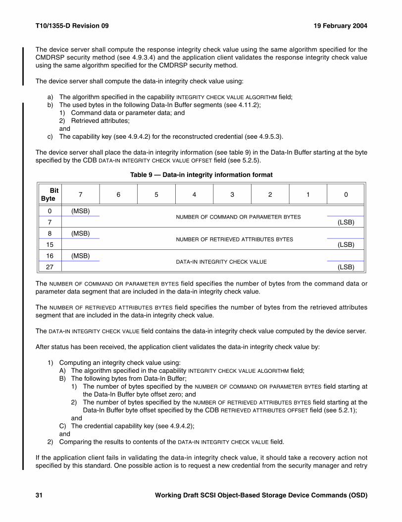
T10/1355-D Revision 09 19 February 2004
The device server shall compute the response integrity check value using the same algorithm specified for theCMDRSP security method (see 4.9.3.4) and the application client validates the response integrity check valueusing the same algorithm specified for the CMDRSP security method.
The device server shall compute the data-in integrity check value using:
a) The algorithm specified in the capability INTEGRITY CHECK VALUE ALGORITHM field;b) The used bytes in the following Data-In Buffer segments (see 4.11.2);
1) Command data or parameter data; and2) Retrieved attributes;and
c) The capability key (see 4.9.4.2) for the reconstructed credential (see 4.9.5.3).
The device server shall place the data-in integrity information (see table 9) in the Data-In Buffer starting at the bytespecified by the CDB DATA-IN INTEGRITY CHECK VALUE OFFSET field (see 5.2.5).
The NUMBER OF COMMAND OR PARAMETER BYTES field specifies the number of bytes from the command data orparameter data segment that are included in the data-in integrity check value.
The NUMBER OF RETRIEVED ATTRIBUTES BYTES field specifies the number of bytes from the retrieved attributessegment that are included in the data-in integrity check value.
The DATA-IN INTEGRITY CHECK VALUE field contains the data-in integrity check value computed by the device server.
After status has been received, the application client validates the data-in integrity check value by:
1) Computing an integrity check value using:A) The algorithm specified in the capability INTEGRITY CHECK VALUE ALGORITHM field;B) The following bytes from Data-In Buffer;
1) The number of bytes specified by the NUMBER OF COMMAND OR PARAMETER BYTES field starting atthe Data-In Buffer byte offset zero; and
2) The number of bytes specified by the NUMBER OF RETRIEVED ATTRIBUTES BYTES field starting at theData-In Buffer byte offset specified by the CDB RETRIEVED ATTRIBUTES OFFSET field (see 5.2.1);
andC) The credential capability key (see 4.9.4.2);and
2) Comparing the results to contents of the DATA-IN INTEGRITY CHECK VALUE field.
If the application client fails in validating the data-in integrity check value, it should take a recovery action notspecified by this standard. One possible action is to request a new credential from the security manager and retry
Table 9 — Data-in integrity information format
BitByte
7 6 5 4 3 2 1 0
0 (MSB)NUMBER OF COMMAND OR PARAMETER BYTES
7 (LSB)
8 (MSB)NUMBER OF RETRIEVED ATTRIBUTES BYTES
15 (LSB)
16 (MSB)DATA-IN INTEGRITY CHECK VALUE
27 (LSB)
31 Working Draft SCSI Object-Based Storage Device Commands (OSD)
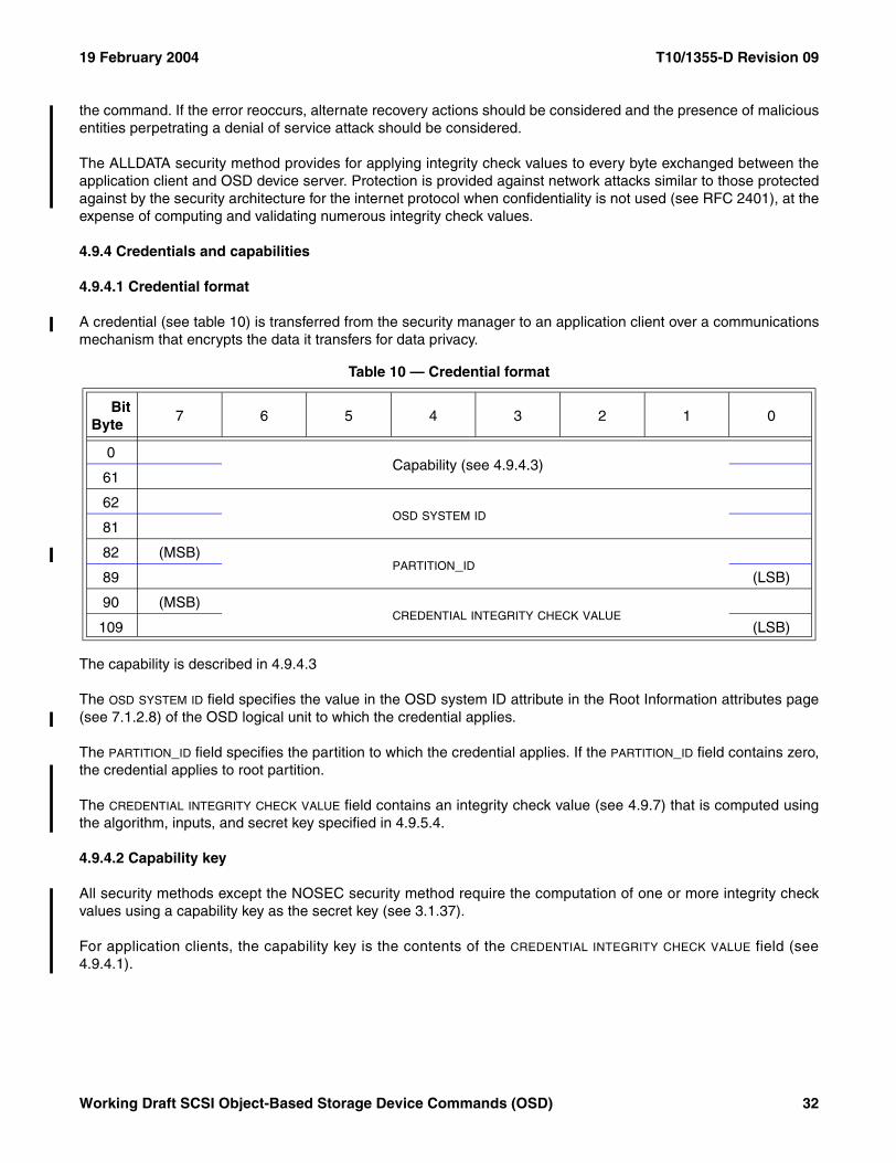
19 February 2004 T10/1355-D Revision 09
the command. If the error reoccurs, alternate recovery actions should be considered and the presence of maliciousentities perpetrating a denial of service attack should be considered.
The ALLDATA security method provides for applying integrity check values to every byte exchanged between theapplication client and OSD device server. Protection is provided against network attacks similar to those protectedagainst by the security architecture for the internet protocol when confidentiality is not used (see RFC 2401), at theexpense of computing and validating numerous integrity check values.
4.9.4 Credentials and capabilities
4.9.4.1 Credential format
A credential (see table 10) is transferred from the security manager to an application client over a communicationsmechanism that encrypts the data it transfers for data privacy.
The capability is described in 4.9.4.3
The OSD SYSTEM ID field specifies the value in the OSD system ID attribute in the Root Information attributes page(see 7.1.2.8) of the OSD logical unit to which the credential applies.
The PARTITION_ID field specifies the partition to which the credential applies. If the PARTITION_ID field contains zero,the credential applies to root partition.
The CREDENTIAL INTEGRITY CHECK VALUE field contains an integrity check value (see 4.9.7) that is computed usingthe algorithm, inputs, and secret key specified in 4.9.5.4.
4.9.4.2 Capability key
All security methods except the NOSEC security method require the computation of one or more integrity checkvalues using a capability key as the secret key (see 3.1.37).
For application clients, the capability key is the contents of the CREDENTIAL INTEGRITY CHECK VALUE field (see4.9.4.1).
Table 10 — Credential format
BitByte
7 6 5 4 3 2 1 0
0
Capability (see 4.9.4.3)
61
62 OSD SYSTEM ID
81
82 (MSB)PARTITION_ID
89 (LSB)
90 (MSB)CREDENTIAL INTEGRITY CHECK VALUE
109 (LSB)
Working Draft SCSI Object-Based Storage Device Commands (OSD) 32
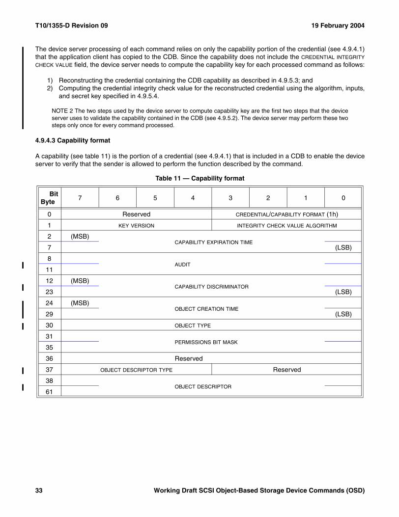
T10/1355-D Revision 09 19 February 2004
The device server processing of each command relies on only the capability portion of the credential (see 4.9.4.1)that the application client has copied to the CDB. Since the capability does not include the CREDENTIAL INTEGRITY
CHECK VALUE field, the device server needs to compute the capability key for each processed command as follows:
1) Reconstructing the credential containing the CDB capability as described in 4.9.5.3; and2) Computing the credential integrity check value for the reconstructed credential using the algorithm, inputs,
and secret key specified in 4.9.5.4.
NOTE 2 The two steps used by the device server to compute capability key are the first two steps that the deviceserver uses to validate the capability contained in the CDB (see 4.9.5.2). The device server may perform these twosteps only once for every command processed.
4.9.4.3 Capability format
A capability (see table 11) is the portion of a credential (see 4.9.4.1) that is included in a CDB to enable the deviceserver to verify that the sender is allowed to perform the function described by the command.
Table 11 — Capability format
BitByte
7 6 5 4 3 2 1 0
0 Reserved CREDENTIAL/CAPABILITY FORMAT (1h)
1 KEY VERSION INTEGRITY CHECK VALUE ALGORITHM
2 (MSB)CAPABILITY EXPIRATION TIME
7 (LSB)
8AUDIT
11
12 (MSB)CAPABILITY DISCRIMINATOR
23 (LSB)
24 (MSB)OBJECT CREATION TIME
29 (LSB)
30 OBJECT TYPE
31PERMISSIONS BIT MASK
35
36 Reserved
37 OBJECT DESCRIPTOR TYPE Reserved
38 OBJECT DESCRIPTOR
61
33 Working Draft SCSI Object-Based Storage Device Commands (OSD)
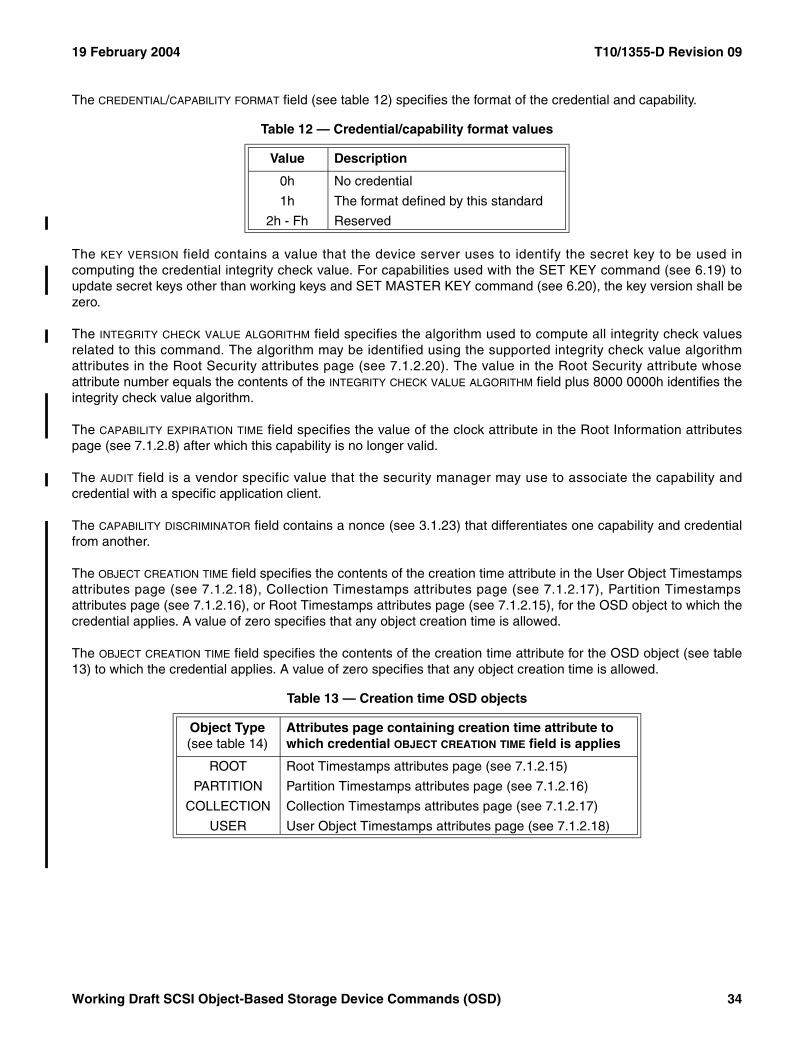
19 February 2004 T10/1355-D Revision 09
The CREDENTIAL/CAPABILITY FORMAT field (see table 12) specifies the format of the credential and capability.
The KEY VERSION field contains a value that the device server uses to identify the secret key to be used incomputing the credential integrity check value. For capabilities used with the SET KEY command (see 6.19) toupdate secret keys other than working keys and SET MASTER KEY command (see 6.20), the key version shall bezero.
The INTEGRITY CHECK VALUE ALGORITHM field specifies the algorithm used to compute all integrity check valuesrelated to this command. The algorithm may be identified using the supported integrity check value algorithmattributes in the Root Security attributes page (see 7.1.2.20). The value in the Root Security attribute whoseattribute number equals the contents of the INTEGRITY CHECK VALUE ALGORITHM field plus 8000 0000h identifies theintegrity check value algorithm.
The CAPABILITY EXPIRATION TIME field specifies the value of the clock attribute in the Root Information attributespage (see 7.1.2.8) after which this capability is no longer valid.
The AUDIT field is a vendor specific value that the security manager may use to associate the capability andcredential with a specific application client.
The CAPABILITY DISCRIMINATOR field contains a nonce (see 3.1.23) that differentiates one capability and credentialfrom another.
The OBJECT CREATION TIME field specifies the contents of the creation time attribute in the User Object Timestampsattributes page (see 7.1.2.18), Collection Timestamps attributes page (see 7.1.2.17), Partition Timestampsattributes page (see 7.1.2.16), or Root Timestamps attributes page (see 7.1.2.15), for the OSD object to which thecredential applies. A value of zero specifies that any object creation time is allowed.
The OBJECT CREATION TIME field specifies the contents of the creation time attribute for the OSD object (see table13) to which the credential applies. A value of zero specifies that any object creation time is allowed.
Table 12 — Credential/capability format values
Value Description
0h No credential
1h The format defined by this standard
2h - Fh Reserved
Table 13 — Creation time OSD objects
Object Type(see table 14)
Attributes page containing creation time attribute to which credential OBJECT CREATION TIME field is applies
ROOT Root Timestamps attributes page (see 7.1.2.15)
PARTITION Partition Timestamps attributes page (see 7.1.2.16)
COLLECTION Collection Timestamps attributes page (see 7.1.2.17)
USER User Object Timestamps attributes page (see 7.1.2.18)
Working Draft SCSI Object-Based Storage Device Commands (OSD) 34
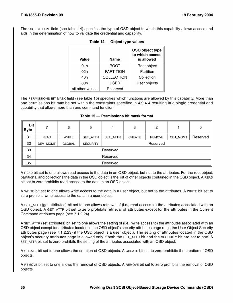
T10/1355-D Revision 09 19 February 2004
The OBJECT TYPE field (see table 14) specifies the type of OSD object to which this capability allows access andaids in the determination of how to validate the credential and capability.
The PERMISSIONS BIT MASK field (see table 15) specifies which functions are allowed by this capability. More thanone permissions bit may be set within the constraints specified in 4.9.4.4 resulting in a single credential andcapability that allows more than one command function.
A READ bit set to one allows read access to the data in an OSD object, but not to the attributes. For the root object,partitions, and collections the data in the OSD object is the list of other objects contained in the OSD object. A READ
bit set to zero prohibits read access to the data in an OSD object.
A WRITE bit set to one allows write access to the data in a user object, but not to the attributes. A WRITE bit set tozero prohibits write access to the data in a user object.
A GET_ATTR (get attributes) bit set to one allows retrieval of (i.e., read access to) the attributes associated with anOSD object. A GET_ATTR bit set to zero prohibits retrieval of attributes except for the attributes in the CurrentCommand attributes page (see 7.1.2.24).
A SET_ATTR (set attributes) bit set to one allows the setting of (i.e., write access to) the attributes associated with anOSD object except for attributes located in the OSD object’s security attributes page (e.g., the User Object Securityattributes page (see 7.1.2.23) if the OSD object is a user object). The setting of attributes located in the OSDobject’s security attributes page is allowed only if both the SET_ATTR bit and the SECURITY bit are set to one. ASET_ATTR bit set to zero prohibits the setting of the attributes associated with an OSD object.
A CREATE bit set to one allows the creation of OSD objects. A CREATE bit set to zero prohibits the creation of OSDobjects.
A REMOVE bit set to one allows the removal of OSD objects. A REMOVE bit set to zero prohibits the removal of OSDobjects.
Table 14 — Object type values
Value Name
OSO object type to which access
is allowed
01h ROOT Root object
02h PARTITION Partition
40h COLLECTION Collection
80h USER User objects
all other values Reserved
Table 15 — Permissions bit mask format
BitByte
7 6 5 4 3 2 1 0
31 READ WRITE GET_ATTR SET_ATTR CREATE REMOVE OBJ_MGMT Reserved
32 DEV_MGMT GLOBAL SECURITY Reserved
33 Reserved
34 Reserved
35 Reserved
35 Working Draft SCSI Object-Based Storage Device Commands (OSD)
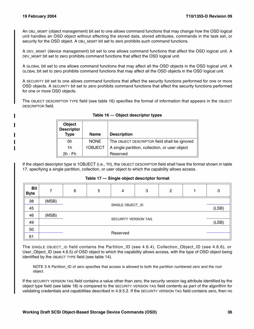
19 February 2004 T10/1355-D Revision 09
An OBJ_MGMT (object management) bit set to one allows command functions that may change how the OSD logicalunit handles an OSD object without affecting the stored data, stored attributes, commands in the task set, orsecurity for the OSD object. A OBJ_MGMT bit set to zero prohibits such command functions.
A DEV_MGMT (device management) bit set to one allows command functions that affect the OSD logical unit. ADEV_MGMT bit set to zero prohibits command functions that affect the OSD logical unit.
A GLOBAL bit set to one allows command functions that may affect all the OSD objects in the OSD logical unit. AGLOBAL bit set to zero prohibits command functions that may affect all the OSD objects in the OSD logical unit.
A SECURITY bit set to one allows command functions that affect the security functions performed for one or moreOSD objects. A SECURITY bit set to zero prohibits command functions that affect the security functions performedfor one or more OSD objects.
The OBJECT DESCRIPTOR TYPE field (see table 16) specifies the format of information that appears in the OBJECT
DESCRIPTOR field.
If the object descriptor type is 1OBJECT (i.e., 1h), the OBJECT DESCRIPTOR field shall have the format shown in table17, specifying a single partition, collection, or user object to which the capability allows access.
The SINGLE OBJECT_ID field contains the Partition_ID (see 4.6.4), Collection_Object_ID (see 4.6.6), orUser_Object_ID (see 4.6.5) of OSD object to which the capability allows access, with the type of OSD object beingidentified by the OBJECT TYPE field (see table 14).
NOTE 3 A Partition_ID of zero specifies that access is allowed to both the partition numbered zero and the rootobject.
If the SECURITY VERSION TAG field contains a value other than zero, the security version tag attribute identified by theobject type field (see table 18) is compared to the SECURITY VERSION TAG field contents as part of the algorithm forvalidating credentials and capabilities described in 4.9.5.2. If the SECURITY VERSION TAG field contains zero, then no
Table 16 — Object descriptor types
Object Descriptor
Type Name Description
0h NONE The OBJECT DESCRIPTOR field shall be ignored
1h 1OBJECT A single partition, collection, or user object
2h - Fh Reserved
Table 17 — Single object descriptor format
BitByte
7 6 5 4 3 2 1 0
38 (MSB)SINGLE OBJECT_ID
45 (LSB)
46 (MSB)SECURITY VERSION TAG
49 (LSB)
50 Reserved
61
Working Draft SCSI Object-Based Storage Device Commands (OSD) 36
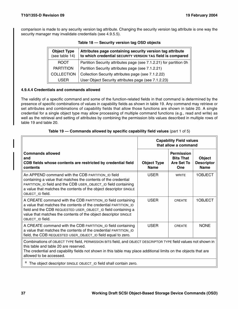
T10/1355-D Revision 09 19 February 2004
comparison is made to any security version tag attribute. Changing the security version tag attribute is one way thesecurity manager may invalidate credentials (see 4.9.5.5).
4.9.4.4 Credentials and commands allowed
The validity of a specific command and some of the function-related fields in that command is determined by thepresence of specific combinations of values in capability fields as shown in table 19. Any command may retrieve orset attributes and combinations of capability fields that allow those functions are shown in table 20. A singlecredential for a single object type may allow processing of multiple command functions (e.g., read and write) aswell as the retrieval and setting of attributes by combining the permission bits values described in multiple rows oftable 19 and table 20.
Table 18 — Security version tag OSD objects
Object Type(see table 14)
Attributes page containing security version tag attribute to which credential SECURITY VERSION TAG field is compared
ROOT Partition Security attributes page (see 7.1.2.21) for partition 0h
PARTITION Partition Security attributes page (see 7.1.2.21)
COLLECTION Collection Security attributes page (see 7.1.2.22)
USER User Object Security attributes page (see 7.1.2.23)
Table 19 — Commands allowed by specific capability field values (part 1 of 5)
Commands allowedandCDB fields whose contents are restricted by credential field contents
Capability Field valuesthat allow a command
Object Type Name
Permission Bits That
Are Set To One
Object Descriptor
Name
An APPEND command with the CDB PARTITION_ID field containing a value that matches the contents of the credential PARTITION_ID field and the CDB USER_OBJECT_ID field containing a value that matches the contents of the object descriptor SINGLE OBJECT_ID field.
USER WRITE 1OBJECT
A CREATE command with the CDB PARTITION_ID field containing a value that matches the contents of the credential PARTITION_ID field and the CDB REQUESTED USER_OBJECT_ID field containing a value that matches the contents of the object descriptor SINGLE OBJECT_ID field.
USER CREATE 1OBJECT
A CREATE command with the CDB PARTITION_ID field containing a value that matches the contents of the credential PARTITION_ID field, the CDB REQUESTED USER_OBJECT_ID field equal to zero.
USER CREATE NONE
Combinations of OBJECT TYPE field, PERMISSION BITS field, and OBJECT DESCRIPTOR TYPE field values not shown in this table and table 20 are reserved.The credential and capability fields not shown in this table may place additional limits on the objects that are allowed to be accessed.
a The object descriptor SINGLE OBJECT_ID field shall contain zero.
37 Working Draft SCSI Object-Based Storage Device Commands (OSD)
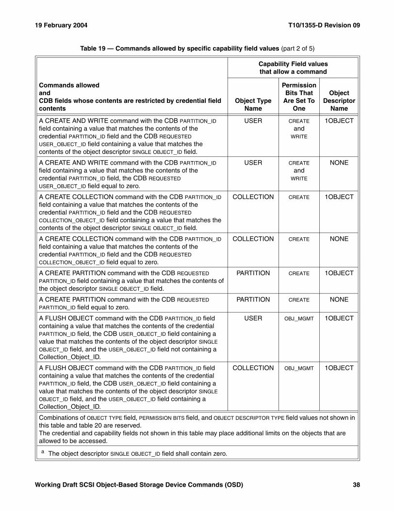
19 February 2004 T10/1355-D Revision 09
A CREATE AND WRITE command with the CDB PARTITION_ID field containing a value that matches the contents of the credential PARTITION_ID field and the CDB REQUESTED USER_OBJECT_ID field containing a value that matches the contents of the object descriptor SINGLE OBJECT_ID field.
USER CREATE
andWRITE
1OBJECT
A CREATE AND WRITE command with the CDB PARTITION_ID field containing a value that matches the contents of the credential PARTITION_ID field, the CDB REQUESTED USER_OBJECT_ID field equal to zero.
USER CREATE
andWRITE
NONE
A CREATE COLLECTION command with the CDB PARTITION_ID field containing a value that matches the contents of the credential PARTITION_ID field and the CDB REQUESTED COLLECTION_OBJECT_ID field containing a value that matches the contents of the object descriptor SINGLE OBJECT_ID field.
COLLECTION CREATE 1OBJECT
A CREATE COLLECTION command with the CDB PARTITION_ID field containing a value that matches the contents of the credential PARTITION_ID field and the CDB REQUESTED COLLECTION_OBJECT_ID field equal to zero.
COLLECTION CREATE NONE
A CREATE PARTITION command with the CDB REQUESTED PARTITION_ID field containing a value that matches the contents of the object descriptor SINGLE OBJECT_ID field.
PARTITION CREATE 1OBJECT
A CREATE PARTITION command with the CDB REQUESTED PARTITION_ID field equal to zero.
PARTITION CREATE NONE
A FLUSH OBJECT command with the CDB PARTITION_ID field containing a value that matches the contents of the credential PARTITION_ID field, the CDB USER_OBJECT_ID field containing a value that matches the contents of the object descriptor SINGLE OBJECT_ID field, and the USER_OBJECT_ID field not containing a Collection_Object_ID.
USER OBJ_MGMT 1OBJECT
A FLUSH OBJECT command with the CDB PARTITION_ID field containing a value that matches the contents of the credential PARTITION_ID field, the CDB USER_OBJECT_ID field containing a value that matches the contents of the object descriptor SINGLE OBJECT_ID field, and the USER_OBJECT_ID field containing a Collection_Object_ID.
COLLECTION OBJ_MGMT 1OBJECT
Table 19 — Commands allowed by specific capability field values (part 2 of 5)
Commands allowedandCDB fields whose contents are restricted by credential field contents
Capability Field valuesthat allow a command
Object Type Name
Permission Bits That
Are Set To One
Object Descriptor
Name
Combinations of OBJECT TYPE field, PERMISSION BITS field, and OBJECT DESCRIPTOR TYPE field values not shown in this table and table 20 are reserved.The credential and capability fields not shown in this table may place additional limits on the objects that are allowed to be accessed.
a The object descriptor SINGLE OBJECT_ID field shall contain zero.
Working Draft SCSI Object-Based Storage Device Commands (OSD) 38
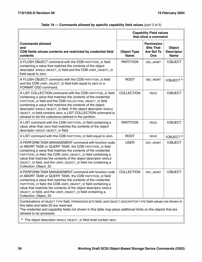
T10/1355-D Revision 09 19 February 2004
A FLUSH OBJECT command with the CDB PARTITION_ID field containing a value that matches the contents of the object descriptor SINGLE OBJECT_ID field and the CDB USER_OBJECT_ID field equal to zero.
PARTITION OBJ_MGMT 1OBJECT
A FLUSH OBJECT command with the CDB PARTITION_ID field and the CDB USER_OBJECT_ID field both equal to zero or a FORMAT OSD command.
ROOT OBJ_MGMT 1OBJECT a
A LIST COLLECTION command with the CDB PARTITION_ID field containing a value that matches the contents of the credential PARTITION_ID field and the CDB COLLECTION_OBJECT_ID field containing a value that matches the contents of the object descriptor SINGLE OBJECT_ID field. If the object descriptor SINGLE OBJECT_ID field contains zero, a LIST COLLECTION command is allowed to list the collections defined in the partition.
COLLECTION READ 1OBJECT
A LIST command with the CDB PARTITION_ID field containing a value other than zero that matches the contents of the object descriptor SINGLE OBJECT_ID field.
PARTITION READ 1OBJECT
A LIST command with the CDB PARTITION_ID field equal to zero. ROOT READ 1OBJECT a
A PERFORM TASK MANAGEMENT command with function code of ABORT TASK or QUERY TASK, the CDB PARTITION_ID field containing a value that matches the contents of the credential PARTITION_ID field, the CDB USER_OBJECT_ID field containing a value that matches the contents of the object descriptor SINGLE OBJECT_ID field, and the USER_OBJECT_ID field not containing a Collection_Object_ID.
USER DEV_MGMT 1OBJECT
A PERFORM TASK MANAGEMENT command with function code of ABORT TASK or QUERY TASK, the CDB PARTITION_ID field containing a value that matches the contents of the credential PARTITION_ID field, the CDB USER_OBJECT_ID field containing a value that matches the contents of the object descriptor SINGLE OBJECT_ID field, and the USER_OBJECT_ID field containing a Collection_Object_ID.
COLLECTION DEV_MGMT 1OBJECT
Table 19 — Commands allowed by specific capability field values (part 3 of 5)
Commands allowedandCDB fields whose contents are restricted by credential field contents
Capability Field valuesthat allow a command
Object Type Name
Permission Bits That
Are Set To One
Object Descriptor
Name
Combinations of OBJECT TYPE field, PERMISSION BITS field, and OBJECT DESCRIPTOR TYPE field values not shown in this table and table 20 are reserved.The credential and capability fields not shown in this table may place additional limits on the objects that are allowed to be accessed.
a The object descriptor SINGLE OBJECT_ID field shall contain zero.
39 Working Draft SCSI Object-Based Storage Device Commands (OSD)
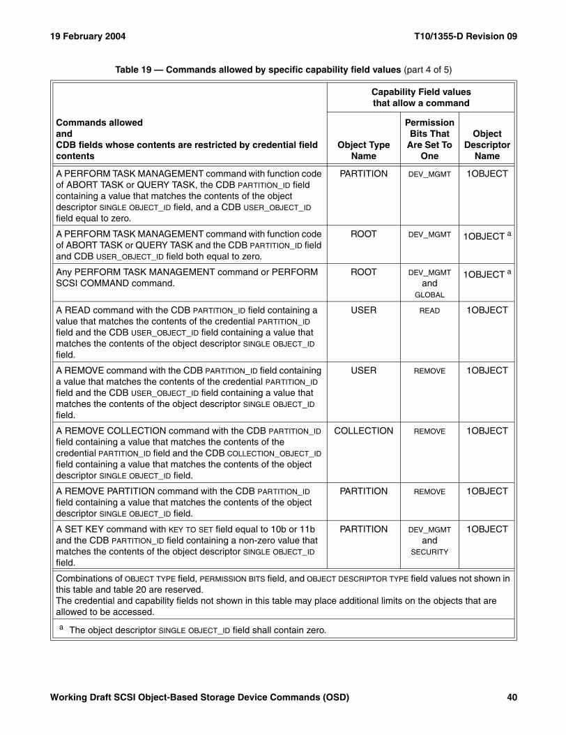
19 February 2004 T10/1355-D Revision 09
A PERFORM TASK MANAGEMENT command with function code of ABORT TASK or QUERY TASK, the CDB PARTITION_ID field containing a value that matches the contents of the object descriptor SINGLE OBJECT_ID field, and a CDB USER_OBJECT_ID field equal to zero.
PARTITION DEV_MGMT 1OBJECT
A PERFORM TASK MANAGEMENT command with function code of ABORT TASK or QUERY TASK and the CDB PARTITION_ID field and CDB USER_OBJECT_ID field both equal to zero.
ROOT DEV_MGMT 1OBJECT a
Any PERFORM TASK MANAGEMENT command or PERFORM SCSI COMMAND command.
ROOT DEV_MGMT and
GLOBAL
1OBJECT a
A READ command with the CDB PARTITION_ID field containing a value that matches the contents of the credential PARTITION_ID field and the CDB USER_OBJECT_ID field containing a value that matches the contents of the object descriptor SINGLE OBJECT_ID field.
USER READ 1OBJECT
A REMOVE command with the CDB PARTITION_ID field containing a value that matches the contents of the credential PARTITION_ID field and the CDB USER_OBJECT_ID field containing a value that matches the contents of the object descriptor SINGLE OBJECT_ID field.
USER REMOVE 1OBJECT
A REMOVE COLLECTION command with the CDB PARTITION_ID field containing a value that matches the contents of the credential PARTITION_ID field and the CDB COLLECTION_OBJECT_ID field containing a value that matches the contents of the object descriptor SINGLE OBJECT_ID field.
COLLECTION REMOVE 1OBJECT
A REMOVE PARTITION command with the CDB PARTITION_ID field containing a value that matches the contents of the object descriptor SINGLE OBJECT_ID field.
PARTITION REMOVE 1OBJECT
A SET KEY command with KEY TO SET field equal to 10b or 11b and the CDB PARTITION_ID field containing a non-zero value that matches the contents of the object descriptor SINGLE OBJECT_ID field.
PARTITION DEV_MGMT and
SECURITY
1OBJECT
Table 19 — Commands allowed by specific capability field values (part 4 of 5)
Commands allowedandCDB fields whose contents are restricted by credential field contents
Capability Field valuesthat allow a command
Object Type Name
Permission Bits That
Are Set To One
Object Descriptor
Name
Combinations of OBJECT TYPE field, PERMISSION BITS field, and OBJECT DESCRIPTOR TYPE field values not shown in this table and table 20 are reserved.The credential and capability fields not shown in this table may place additional limits on the objects that are allowed to be accessed.
a The object descriptor SINGLE OBJECT_ID field shall contain zero.
Working Draft SCSI Object-Based Storage Device Commands (OSD) 40
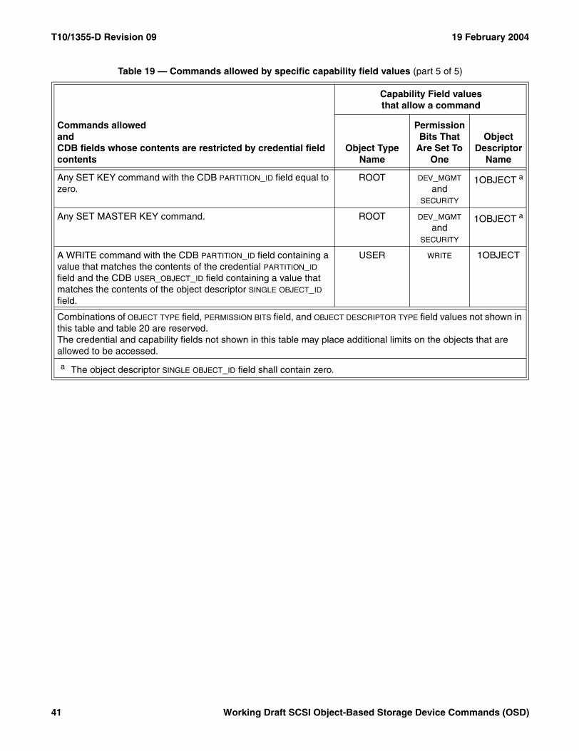
T10/1355-D Revision 09 19 February 2004
Any SET KEY command with the CDB PARTITION_ID field equal to zero.
ROOT DEV_MGMT and
SECURITY
1OBJECT a
Any SET MASTER KEY command. ROOT DEV_MGMT and
SECURITY
1OBJECT a
A WRITE command with the CDB PARTITION_ID field containing a value that matches the contents of the credential PARTITION_ID field and the CDB USER_OBJECT_ID field containing a value that matches the contents of the object descriptor SINGLE OBJECT_ID field.
USER WRITE 1OBJECT
Table 19 — Commands allowed by specific capability field values (part 5 of 5)
Commands allowedandCDB fields whose contents are restricted by credential field contents
Capability Field valuesthat allow a command
Object Type Name
Permission Bits That
Are Set To One
Object Descriptor
Name
Combinations of OBJECT TYPE field, PERMISSION BITS field, and OBJECT DESCRIPTOR TYPE field values not shown in this table and table 20 are reserved.The credential and capability fields not shown in this table may place additional limits on the objects that are allowed to be accessed.
a The object descriptor SINGLE OBJECT_ID field shall contain zero.
41 Working Draft SCSI Object-Based Storage Device Commands (OSD)
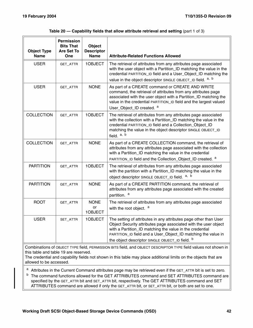
19 February 2004 T10/1355-D Revision 09
Table 20 — Capability fields that allow attribute retrieval and setting (part 1 of 3)
Object Type Name
Permission Bits That
Are Set To One
Object Descriptor
Name Attribute-Related Functions Allowed
USER GET_ATTR 1OBJECT The retrieval of attributes from any attributes page associated with the user object with a Partition_ID matching the value in the credential PARTITION_ID field and a User_Object_ID matching the
value in the object descriptor SINGLE OBJECT_ID field. a, b
USER GET_ATTR NONE As part of a CREATE command or CREATE AND WRITE command, the retrieval of attributes from any attributes page associated with the user object with a Partition_ID matching the value in the credential PARTITION_ID field and the largest valued
User_Object_ID created. a
COLLECTION GET_ATTR 1OBJECT The retrieval of attributes from any attributes page associated with the collection with a Partition_ID matching the value in the credential PARTITION_ID field and a Collection_Object_ID matching the value in the object descriptor SINGLE OBJECT_ID
field. a, b
COLLECTION GET_ATTR NONE As part of a CREATE COLLECTION command, the retrieval of attributes from any attributes page associated with the collection with a Partition_ID matching the value in the credential
PARTITION_ID field and the Collection_Object_ID created. a
PARTITION GET_ATTR 1OBJECT The retrieval of attributes from any attributes page associated with the partition with a Partition_ID matching the value in the
object descriptor SINGLE OBJECT_ID field. a, b
PARTITION GET_ATTR NONE As part of a CREATE PARTITION command, the retrieval of attributes from any attributes page associated with the created
partition. a
ROOT GET_ATTR NONEor
1OBJECT
The retrieval of attributes from any attributes page associated
with the root object. a
USER SET_ATTR 1OBJECT The setting of attributes in any attributes page other than User Object Security attributes page associated with the user object with a Partition_ID matching the value in the credential PARTITION_ID field and a User_Object_ID matching the value in
the object descriptor SINGLE OBJECT_ID field. b
Combinations of OBJECT TYPE field, PERMISSION BITS field, and OBJECT DESCRIPTOR TYPE field values not shown in this table and table 19 are reserved.The credential and capability fields not shown in this table may place additional limits on the objects that are allowed to be accessed.
a Attributes in the Current Command attributes page may be retrieved even if the GET_ATTR bit is set to zero.b The command functions allowed for the GET ATTRIBUTES command and SET ATTRIBUTES command are
specified by the GET_ATTR bit and SET_ATTR bit, respectively. The GET ATTRIBUTES command and SET ATTRIBUTES command are allowed if only the GET_ATTR bit, or SET_ATTR bit, or both are set to one.
Working Draft SCSI Object-Based Storage Device Commands (OSD) 42
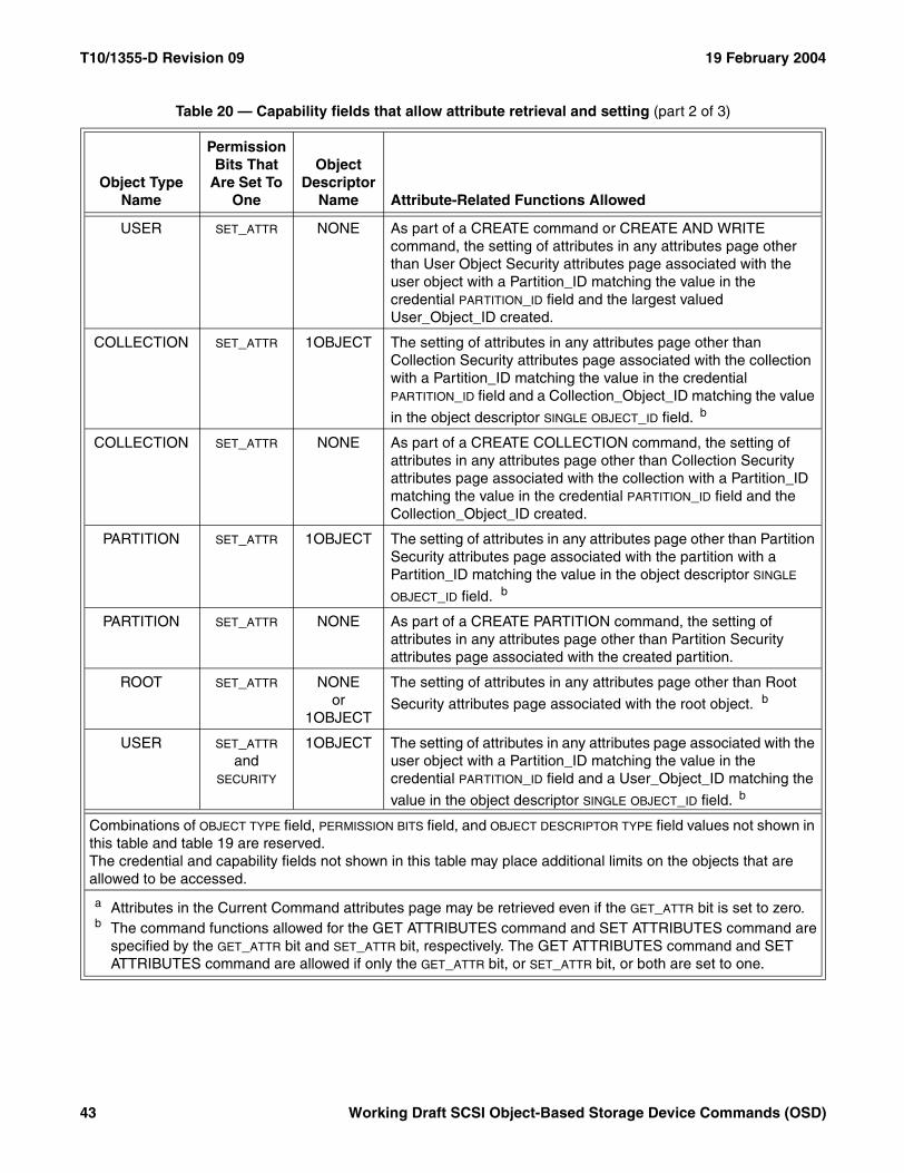
T10/1355-D Revision 09 19 February 2004
USER SET_ATTR NONE As part of a CREATE command or CREATE AND WRITE command, the setting of attributes in any attributes page other than User Object Security attributes page associated with the user object with a Partition_ID matching the value in the credential PARTITION_ID field and the largest valued User_Object_ID created.
COLLECTION SET_ATTR 1OBJECT The setting of attributes in any attributes page other than Collection Security attributes page associated with the collection with a Partition_ID matching the value in the credential PARTITION_ID field and a Collection_Object_ID matching the value
in the object descriptor SINGLE OBJECT_ID field. b
COLLECTION SET_ATTR NONE As part of a CREATE COLLECTION command, the setting of attributes in any attributes page other than Collection Security attributes page associated with the collection with a Partition_ID matching the value in the credential PARTITION_ID field and the Collection_Object_ID created.
PARTITION SET_ATTR 1OBJECT The setting of attributes in any attributes page other than Partition Security attributes page associated with the partition with a Partition_ID matching the value in the object descriptor SINGLE
OBJECT_ID field. b
PARTITION SET_ATTR NONE As part of a CREATE PARTITION command, the setting of attributes in any attributes page other than Partition Security attributes page associated with the created partition.
ROOT SET_ATTR NONEor
1OBJECT
The setting of attributes in any attributes page other than Root
Security attributes page associated with the root object. b
USER SET_ATTR and
SECURITY
1OBJECT The setting of attributes in any attributes page associated with the user object with a Partition_ID matching the value in the credential PARTITION_ID field and a User_Object_ID matching the
value in the object descriptor SINGLE OBJECT_ID field. b
Table 20 — Capability fields that allow attribute retrieval and setting (part 2 of 3)
Object Type Name
Permission Bits That
Are Set To One
Object Descriptor
Name Attribute-Related Functions Allowed
Combinations of OBJECT TYPE field, PERMISSION BITS field, and OBJECT DESCRIPTOR TYPE field values not shown in this table and table 19 are reserved.The credential and capability fields not shown in this table may place additional limits on the objects that are allowed to be accessed.
a Attributes in the Current Command attributes page may be retrieved even if the GET_ATTR bit is set to zero.b The command functions allowed for the GET ATTRIBUTES command and SET ATTRIBUTES command are
specified by the GET_ATTR bit and SET_ATTR bit, respectively. The GET ATTRIBUTES command and SET ATTRIBUTES command are allowed if only the GET_ATTR bit, or SET_ATTR bit, or both are set to one.
43 Working Draft SCSI Object-Based Storage Device Commands (OSD)
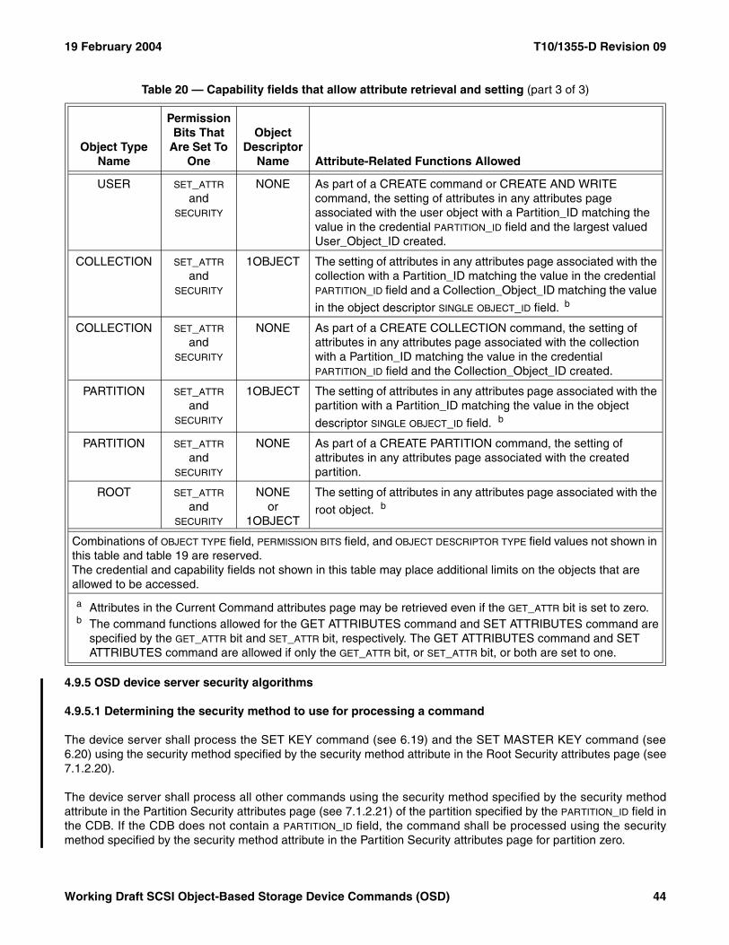
19 February 2004 T10/1355-D Revision 09
4.9.5 OSD device server security algorithms
4.9.5.1 Determining the security method to use for processing a command
The device server shall process the SET KEY command (see 6.19) and the SET MASTER KEY command (see6.20) using the security method specified by the security method attribute in the Root Security attributes page (see7.1.2.20).
The device server shall process all other commands using the security method specified by the security methodattribute in the Partition Security attributes page (see 7.1.2.21) of the partition specified by the PARTITION_ID field inthe CDB. If the CDB does not contain a PARTITION_ID field, the command shall be processed using the securitymethod specified by the security method attribute in the Partition Security attributes page for partition zero.
USER SET_ATTR and
SECURITY
NONE As part of a CREATE command or CREATE AND WRITE command, the setting of attributes in any attributes page associated with the user object with a Partition_ID matching the value in the credential PARTITION_ID field and the largest valued User_Object_ID created.
COLLECTION SET_ATTR and
SECURITY
1OBJECT The setting of attributes in any attributes page associated with the collection with a Partition_ID matching the value in the credential PARTITION_ID field and a Collection_Object_ID matching the value
in the object descriptor SINGLE OBJECT_ID field. b
COLLECTION SET_ATTR and
SECURITY
NONE As part of a CREATE COLLECTION command, the setting of attributes in any attributes page associated with the collection with a Partition_ID matching the value in the credential PARTITION_ID field and the Collection_Object_ID created.
PARTITION SET_ATTR and
SECURITY
1OBJECT The setting of attributes in any attributes page associated with the partition with a Partition_ID matching the value in the object
descriptor SINGLE OBJECT_ID field. b
PARTITION SET_ATTR and
SECURITY
NONE As part of a CREATE PARTITION command, the setting of attributes in any attributes page associated with the created partition.
ROOT SET_ATTR and
SECURITY
NONEor
1OBJECT
The setting of attributes in any attributes page associated with the
root object. b
Table 20 — Capability fields that allow attribute retrieval and setting (part 3 of 3)
Object Type Name
Permission Bits That
Are Set To One
Object Descriptor
Name Attribute-Related Functions Allowed
Combinations of OBJECT TYPE field, PERMISSION BITS field, and OBJECT DESCRIPTOR TYPE field values not shown in this table and table 19 are reserved.The credential and capability fields not shown in this table may place additional limits on the objects that are allowed to be accessed.
a Attributes in the Current Command attributes page may be retrieved even if the GET_ATTR bit is set to zero.b The command functions allowed for the GET ATTRIBUTES command and SET ATTRIBUTES command are
specified by the GET_ATTR bit and SET_ATTR bit, respectively. The GET ATTRIBUTES command and SET ATTRIBUTES command are allowed if only the GET_ATTR bit, or SET_ATTR bit, or both are set to one.
Working Draft SCSI Object-Based Storage Device Commands (OSD) 44
T10/1355-D Revision 09 19 February 2004
4.9.5.2 Credential and capability validation
This subclause describes the process for validating a capability received in a CDB if the security method is use isnot NOSEC. With two exceptions, the processes described in this subclause apply to the validation of allcommands. Additional validation requirements that apply only to the SET KEY command (see 6.19) and SETMASTER KEY command (see 6.20) are specified in 4.9.8.2.
The algorithm for determining which security method to use is specified in 4.9.5.1.
If the security method is use is not NOSEC and a command with zero in the CREDENTIAL/CAPABILITY FORMAT field(see 4.9.4.3) is received, the command shall be terminated with a CHECK CONDITION status, the sense key shallbe set to ILLEGAL REQUEST, and the additional sense code shall be set to INVALID FIELD IN CDB.
The order in which validation actions are described in this subclause follows the order in which the fields beingvalidated appear in the capability (see 4.9.4.3) and credential (see 4.9.4.1). In most cases the order in which thevalidation steps are performed is not critical, but the validation of the request nonce should be performed as earlyin the process as possible to increase the chances of detecting and rejecting duplicate nonces.
It may be possible to optimize the process described in this subclause, but such optimizations are beyond thescope of this standard. In addition to the conditions described in this subclause, the device server may returnCHECK CONDITION status for any anomalies it detects.
The device server validates the capability information in a CDB by:
1) Reconstructing the credential containing the capability as described in 4.9.5.3;2) Computing the credential integrity check value for the reconstructed credential using the algorithm, inputs,
and secret key specified in 4.9.5.4;3) Computing the request integrity check value using:
A) The algorithm specified by the INTEGRITY CHECK VALUE ALGORITHM FIELD in the capability;B) One of the following arrays of bytes:
a) For the CAPKEY security method, the security token (see 4.9.3.2); orb) For the CMDRSP security method and the ALLDATA security method, all the bytes in the CDB with
the bytes in the REQUEST INTEGRITY CHECK VALUE field set to zero;and
C) The credential integrity check value computed in step 2) as the secret key;and
4) Verifying that the request integrity check value matches the contents of the REQUEST INTEGRITY CHECK
VALUE field in the CDB (see 5.2.5).
If the contents in the request integrity check value field in the CDB do not match the computed integrity checkvalue, the command shall be terminated with a CHECK CONDITION status, the sense key shall be set to ILLEGALREQUEST, and the additional sense code shall be set to INVALID FIELD IN CDB.
If the CAPABILITY EXPIRATION TIME field contains a value other than zero and the value of the clock attribute in theRoot Information attributes page is greater than the value in the CAPABILITY EXPIRATION TIME field, the commandshall be terminated with a CHECK CONDITION status, the sense key shall be set to ILLEGAL REQUEST, and theadditional sense code shall be set to INVALID FIELD IN CDB.
Successful use of the capability expiration time requires some degree of synchronization between the clocks of thedevice server and security manager. The protocol for synchronizing the clocks is outside the scope of thisstandard, however, the protocol should be implemented in a secure manner (i.e., it should not be possible for anadversary to set the clock in the device server backwards to enable the replay of expired credentials).
45 Working Draft SCSI Object-Based Storage Device Commands (OSD)
19 February 2004 T10/1355-D Revision 09
If the OBJECT CREATION TIME field contains a value other than zero and the value in the OBJECT CREATION TIME fieldis not identical to the value in the creation time attribute from the associated timestamps attributes page (see table13 in 4.9.4.3), then the command shall be terminated with a CHECK CONDITION status, the sense key shall be setto ILLEGAL REQUEST, and the additional sense code shall be set to INVALID FIELD IN CDB.
If the capability object type, permissions bit mask, and object descriptor do not allow a command function specifiedby the CDB as shown in table 19 (see 4.9.4.3), the command shall be terminated with a CHECK CONDITIONstatus, the sense key shall be set to ILLEGAL REQUEST, and the additional sense code shall be set to INVALIDFIELD IN CDB.
If the capability object type, permissions bit mask, and object descriptor do not allow the attribute retrieval orattribute setting command functions specified by the CDB as shown in table 20 (see 4.9.4.3), the command shallbe terminated with a CHECK CONDITION status, the sense key shall be set to ILLEGAL REQUEST, and theadditional sense code shall be set to INVALID FIELD IN CDB.
If the object descriptor type is 1OBJECT (see 4.9.4.3) and the value in the object descriptor SECURITY VERSION TAG
field is not identical to the value in the security version tag attribute from the associated security attributes page(see table 18 in 4.9.4.3), then the command shall be terminated with a CHECK CONDITION status, the sense keyshall be set to ILLEGAL REQUEST, and the additional sense code shall be set to INVALID FIELD IN CDB.
If the validation of a credential and capability results in a CHECK CONDITION status being returned, the state ofthe OSD objects and attributes shall not be altered in any detectable way.
4.9.5.3 Reconstructing the credential
The device server reconstructs a credential from a CDB capability by:
1) Reconstructing the credential fields as follows:A) Copy the value in the OSD system ID attribute in the Root Information attributes page (see 7.1.2.8) to
the OSD SYSTEM ID field of the reconstructed credential;and
B) Reconstruct the credential PARTITION_ID field as follows:a) If the command is CREATE PARTITION, FORMAT OSD, LIST, PERFORM SCSI COMMAND,
REMOVE PARTITION, or SET KEY, then place zero in PARTITION_ID field of the reconstructedcredential;
b) If the CDB USER_OBJECT_ID field contains zero and the command is FLUSH OBJECT orPERFORM TASK MANAGEMENT, then place zero in PARTITION_ID field of the reconstructedcredential; or
c) Otherwise, copy the contents of the CDB PARTITION_ID field to the PARTITION_ID field of the recon-structed credential;
and2) Copying the capability from the CDB to the reconstructed credential.
4.9.5.4 Computing the credential integrity check value
The credential integrity check value shall be computed using:
a) The algorithm specified by the INTEGRITY CHECK VALUE ALGORITHM FIELD in the capability;b) The following bytes:
A) All of the bytes in all of the fields defined for the credential (see 4.9.4.1);B) Except the bytes in the CREDENTIAL INTEGRITY CHECK VALUE field;and
Working Draft SCSI Object-Based Storage Device Commands (OSD) 46
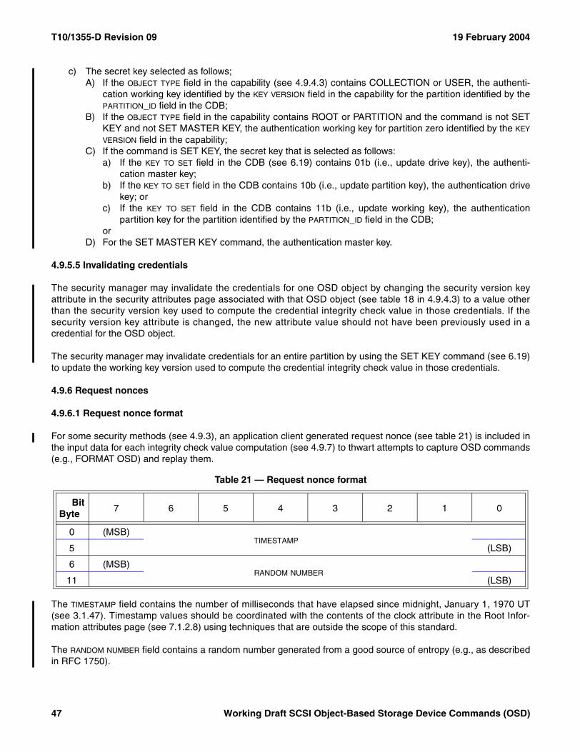
T10/1355-D Revision 09 19 February 2004
c) The secret key selected as follows;A) If the OBJECT TYPE field in the capability (see 4.9.4.3) contains COLLECTION or USER, the authenti-
cation working key identified by the KEY VERSION field in the capability for the partition identified by thePARTITION_ID field in the CDB;
B) If the OBJECT TYPE field in the capability contains ROOT or PARTITION and the command is not SETKEY and not SET MASTER KEY, the authentication working key for partition zero identified by the KEY
VERSION field in the capability;C) If the command is SET KEY, the secret key that is selected as follows:
a) If the KEY TO SET field in the CDB (see 6.19) contains 01b (i.e., update drive key), the authenti-cation master key;
b) If the KEY TO SET field in the CDB contains 10b (i.e., update partition key), the authentication drivekey; or
c) If the KEY TO SET field in the CDB contains 11b (i.e., update working key), the authenticationpartition key for the partition identified by the PARTITION_ID field in the CDB;
orD) For the SET MASTER KEY command, the authentication master key.
4.9.5.5 Invalidating credentials
The security manager may invalidate the credentials for one OSD object by changing the security version keyattribute in the security attributes page associated with that OSD object (see table 18 in 4.9.4.3) to a value otherthan the security version key used to compute the credential integrity check value in those credentials. If thesecurity version key attribute is changed, the new attribute value should not have been previously used in acredential for the OSD object.
The security manager may invalidate credentials for an entire partition by using the SET KEY command (see 6.19)to update the working key version used to compute the credential integrity check value in those credentials.
4.9.6 Request nonces
4.9.6.1 Request nonce format
For some security methods (see 4.9.3), an application client generated request nonce (see table 21) is included inthe input data for each integrity check value computation (see 4.9.7) to thwart attempts to capture OSD commands(e.g., FORMAT OSD) and replay them.
The TIMESTAMP field contains the number of milliseconds that have elapsed since midnight, January 1, 1970 UT(see 3.1.47). Timestamp values should be coordinated with the contents of the clock attribute in the Root Infor-mation attributes page (see 7.1.2.8) using techniques that are outside the scope of this standard.
The RANDOM NUMBER field contains a random number generated from a good source of entropy (e.g., as describedin RFC 1750).
Table 21 — Request nonce format
BitByte
7 6 5 4 3 2 1 0
0 (MSB)TIMESTAMP
5 (LSB)
6 (MSB)RANDOM NUMBER
11 (LSB)
47 Working Draft SCSI Object-Based Storage Device Commands (OSD)
19 February 2004 T10/1355-D Revision 09
If the security method being used does not require generation of request nonce values, the nonce TIMESTAMP fieldshould contain zero.
4.9.6.2 Device server validation of request nonces
If the inputs to an integrity check value computation include a request nonce with a non zero timestamp and thenonce has been used in any previous integrity check value computation, the command shall be terminated with aCHECK CONDITION status, the sense key shall be set to ILLEGAL REQUEST, and the additional sense codeshall be set to NONCE NOT UNIQUE. The command shall be terminated regardless of the success or failure of theprevious command in which the duplicate request nonce appeared (e.g., the request nonce appearing in a WRITEcommand that ultimately fails due to insufficient quota or the request nonce appearing in a CREATE command thatultimately fails because the computed credential integrity check value is wrong shall not be accepted a secondtime).
If the command is being processed using the CMDRSP security method or the ALLDATA security method (see4.9.3) and a request nonce with zero in the TIMESTAMP field is received, the command shall be terminated with aCHECK CONDITION status, the sense key shall be set to ILLEGAL REQUEST, and the additional sense codeshall be set to INVALID FIELD IN CDB.
Device servers may reduce the amount of resources required to remember every request nonce ever received bycomparing the contents of the TIMESTAMP field in each request nonce to the contents of the clock attribute in theRoot Information attributes page (see 7.1.2.8).
Commands containing request nonces with timestamps that are less than the contents of the clock attribute in theRoot Information attributes page minus a delta value may be terminated with a CHECK CONDITION status, withthe sense key set to ILLEGAL REQUEST, and with the additional sense code set to NONCE TIMESTAMP OUT OFRANGE. If a command is terminated in this way, the current contents of the clock attribute in the Root Informationattributes page shall be returned left-aligned and zero-padded (see 3.7.2) in the COMMAND-SPECIFIC INFORMATION
field of the command-specific information sense data descriptor.
If the delta value from the contents of the clock attribute in the Root Information attributes page used to enforceminimum timestamp values is a constant, it should be made available to the application client in the oldest validnonce attribute in the Partition Security attributes page (see 7.1.2.21). If a range of delta values are used to enforceminimum timestamp values, the smallest value in that range should be made available to the application client inthe oldest valid nonce attribute in the Partition Security attributes page.
Commands containing request nonces with timestamps that are greater than the contents of the clock attribute inthe Root Information attributes page plus a delta value may be terminated with a CHECK CONDITION status, thesense key shall be set to ILLEGAL REQUEST, and the additional sense code shall be set to NONCE TIMESTAMPOUT OF RANGE. If a command is terminated in this way, the current contents of the clock attribute in the RootInformation attributes page shall be returned left-aligned and zero-padded (see 3.7.2) in the COMMAND-SPECIFIC
INFORMATION field of the command-specific information sense data descriptor.
If the delta value from the contents of the clock attribute in the Root Information attributes page used to enforcemaximum timestamp values is a constant, it should be made available to the application client in the newest validnonce attribute in the Partition Security attributes page (see 7.1.2.21). If a range of delta values are used to enforcemaximum timestamp values, the smallest value in that range should be made available to the application client inthe newest valid nonce attribute in the Partition Security attributes page.
If the newest valid nonce attribute in the Partition Security attributes page contains a non-zero value and acommand containing a request nonce with a timestamp that is greater than the contents of the clock attribute in theRoot Information attributes page plus newest valid nonce attribute value is received, device server may accept thecommand and treat the nonce as having arrived from far in the future. The minimum number of far in the future
Working Draft SCSI Object-Based Storage Device Commands (OSD) 48
T10/1355-D Revision 09 19 February 2004
nonces accepted shall be made available to the application client in the minimum future requests attribute in thePartition Security attributes page. Optional methods for handling far in the future nonces are described in 4.9.6.3.
4.9.6.3 Far-in-the-future nonces
4.9.6.3.1 Introduction
Device servers may process commands containing request nonces that exceed the sum of the clock attribute in theRoot Information attributes page (see 7.1.2.8) plus newest valid nonce attribute in the Partition Security attributespage (see 7.1.2.21) and use one or both of the following methods to reduce the amount of resources required toremember every request nonce ever received:
a) Restricting the use of one or more capabilities based on the contents of the capability AUDIT field asdescribed in 4.9.6.3.2, or
b) Disabling one or more working keys as described in 4.9.6.3.3.
4.9.6.3.2 Capability restrictions with far in the future nonces
To reduce the amount of resources required to remember every far in the future application client nonce everreceived, the device server may refuse to accept any additional commands containing a specific combination ofcapability AUDIT field and capability KEY VERSION field (see 4.9.4.3) values. If the device server takes this action, itshould terminate the selected command and all future commands containing the selected combination of capabilityAUDIT field and capability KEY VERSION field values with a CHECK CONDITION status, a sense key of ILLEGALREQUEST, and an additional sense code of SECURITY AUDIT VALUE FROZEN.
The device server may repeat the process described in this subclause as often as necessary to reduce the amountof resources required to implement the duplicate nonce checking requirement stated at the beginning of 4.9.6.2.
4.9.6.3.3 Working key restrictions with far in the future nonces
To reduce the amount of resources required to remember every far in the future application client nonce everreceived, the device server may refuse to accept any additional commands that use a credential whose capabilitykey has been computed using a specific working key version (see 4.9.4.3) value. If the device server takes thisaction, it:
a) Should terminate the selected command and all future commands whose capability key has beencomputed using a selected working key version value with a CHECK CONDITION status, a sense key ofILLEGAL REQUEST, and an additional sense code of SECURITY WORKING KEY FROZEN; and
b) Shall set to one the bit in the frozen working key bit mask attribute in the Partition Security attributes page(see 7.1.2.21) that corresponds to the working key version thus selected.
The device server may repeat the process described in this subclause as often as necessary to reduce the amountof resources required to implement the duplicate nonce checking requirement stated at the beginning of 4.9.6.2.
4.9.7 Integrity check values
An integrity check value is a value produced by a cryptographic function (e.g., HMAC-SHA1) based on a secret key(see 4.9.8) that is able to be computed and verified by the entities knowing the secret key. An integrity check valuesare used to verify that:
a) A collection of data fields contain correct values; andb) The values in those data fields were prepared by the entity that created the integrity check value.
49 Working Draft SCSI Object-Based Storage Device Commands (OSD)
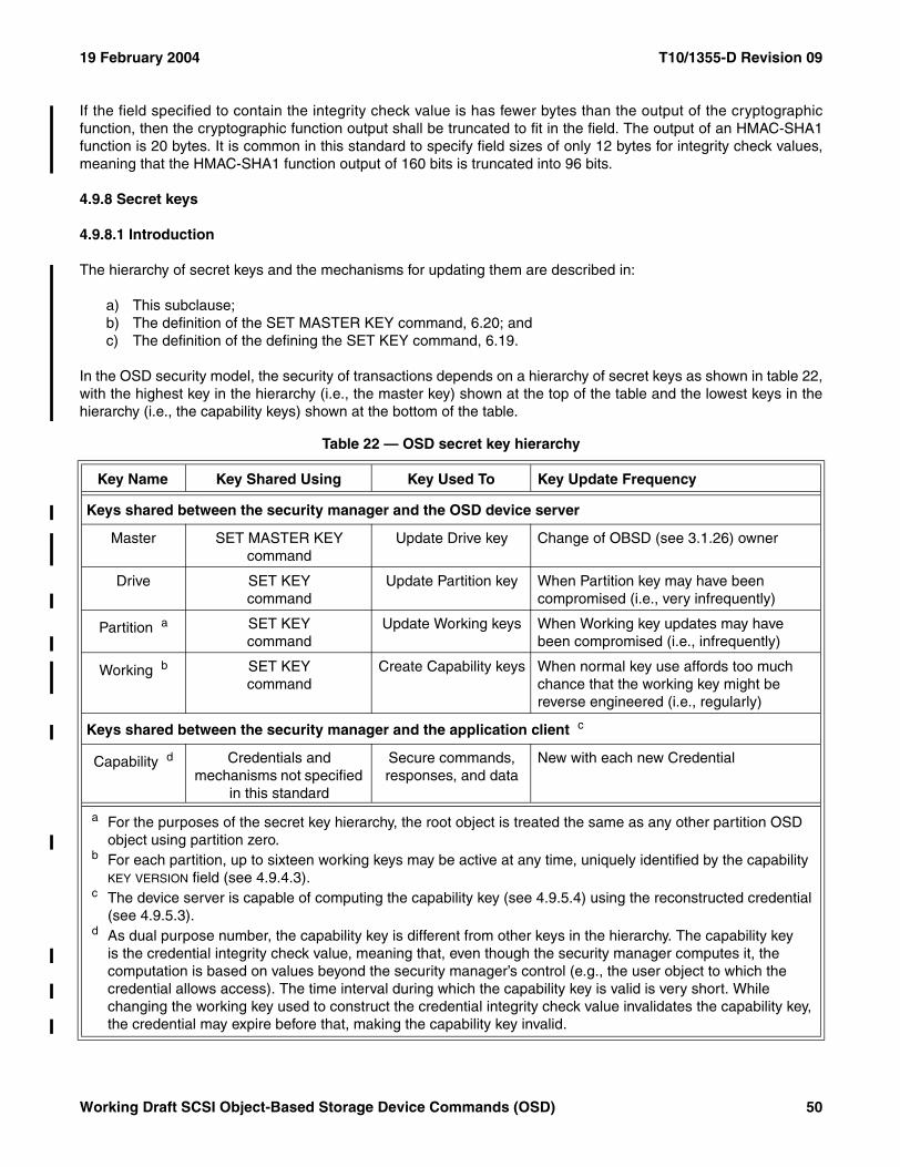
19 February 2004 T10/1355-D Revision 09
If the field specified to contain the integrity check value is has fewer bytes than the output of the cryptographicfunction, then the cryptographic function output shall be truncated to fit in the field. The output of an HMAC-SHA1function is 20 bytes. It is common in this standard to specify field sizes of only 12 bytes for integrity check values,meaning that the HMAC-SHA1 function output of 160 bits is truncated into 96 bits.
4.9.8 Secret keys
4.9.8.1 Introduction
The hierarchy of secret keys and the mechanisms for updating them are described in:
a) This subclause;b) The definition of the SET MASTER KEY command, 6.20; andc) The definition of the defining the SET KEY command, 6.19.
In the OSD security model, the security of transactions depends on a hierarchy of secret keys as shown in table 22,with the highest key in the hierarchy (i.e., the master key) shown at the top of the table and the lowest keys in thehierarchy (i.e., the capability keys) shown at the bottom of the table.
Table 22 — OSD secret key hierarchy
Key Name Key Shared Using Key Used To Key Update Frequency
Keys shared between the security manager and the OSD device server
Master SET MASTER KEY command
Update Drive key Change of OBSD (see 3.1.26) owner
Drive SET KEYcommand
Update Partition key When Partition key may have been compromised (i.e., very infrequently)
Partition a SET KEYcommand
Update Working keys When Working key updates may have been compromised (i.e., infrequently)
Working b SET KEYcommand
Create Capability keys When normal key use affords too much chance that the working key might be reverse engineered (i.e., regularly)
Keys shared between the security manager and the application client c
Capability d Credentials and mechanisms not specified
in this standard
Secure commands, responses, and data
New with each new Credential
a For the purposes of the secret key hierarchy, the root object is treated the same as any other partition OSD object using partition zero.
b For each partition, up to sixteen working keys may be active at any time, uniquely identified by the capability KEY VERSION field (see 4.9.4.3).
c The device server is capable of computing the capability key (see 4.9.5.4) using the reconstructed credential (see 4.9.5.3).
d As dual purpose number, the capability key is different from other keys in the hierarchy. The capability key is the credential integrity check value, meaning that, even though the security manager computes it, the computation is based on values beyond the security manager’s control (e.g., the user object to which the credential allows access). The time interval during which the capability key is valid is very short. While changing the working key used to construct the credential integrity check value invalidates the capability key, the credential may expire before that, making the capability key invalid.
Working Draft SCSI Object-Based Storage Device Commands (OSD) 50
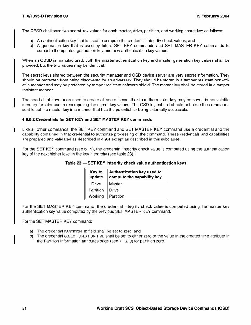
T10/1355-D Revision 09 19 February 2004
The OBSD shall save two secret key values for each master, drive, partition, and working secret key as follows:
a) An authentication key that is used to compute the credential integrity check values; andb) A generation key that is used by future SET KEY commands and SET MASTER KEY commands to
compute the updated generation key and new authentication key values.
When an OBSD is manufactured, both the master authentication key and master generation key values shall beprovided, but the two values may be identical.
The secret keys shared between the security manager and OSD device server are very secret information. Theyshould be protected from being discovered by an adversary. They should be stored in a tamper resistant non-vol-atile manner and may be protected by tamper resistant software shield. The master key shall be stored in a tamperresistant manner.
The seeds that have been used to create all secret keys other than the master key may be saved in nonvolatilememory for later use in recomputing the secret key values. The OSD logical unit should not store the commandssent to set the master key in a manner that has the potential for being externally accessible.
4.9.8.2 Credentials for SET KEY and SET MASTER KEY commands
Like all other commands, the SET KEY command and SET MASTER KEY command use a credential and thecapability contained in that credential to authorize processing of the command. These credentials and capabilitiesare prepared and validated as described in 4.9.4 except as described in this subclause.
For the SET KEY command (see 6.19), the credential integrity check value is computed using the authenticationkey of the next higher level in the key hierarchy (see table 23).
For the SET MASTER KEY command, the credential integrity check value is computed using the master keyauthentication key value computed by the previous SET MASTER KEY command.
For the SET MASTER KEY command:
a) The credential PARTITION_ID field shall be set to zero; andb) The credential OBJECT CREATION TIME shall be set to either zero or the value in the created time attribute in
the Partition Information attributes page (see 7.1.2.9) for partition zero.
Table 23 — SET KEY integrity check value authentication keys
Key to update
Authentication key used to compute the capability key
Drive Master
Partition Drive
Working Partition
51 Working Draft SCSI Object-Based Storage Device Commands (OSD)
19 February 2004 T10/1355-D Revision 09
4.9.8.3 Computing updated generation keys and new authentication keys
The SET KEY command and SET MASTER KEY command shall perform the steps described in this subclause tocompute new generation and authentication keys.
The inputs to the process are:
a) The input key value is one of the following:A) For a SET KEY command, the generation key from the next higher level in the key hierarchy shall be
used (e.g., the drive key generation key is used to create the first partition keys for a newly createdpartition), as selected by the KEY TO SET field in the CDB of that command; or
B) For a SET MASTER KEY command, the previous master key generation key shall be used;b) The seed value, as specified in the seed field of the CDB for the command; andc) The integrity check value algorithm, as specified in the INTEGRITY CHECK VALUE ALGORITHM field in the
capability in the CDB for the command.
The updated generation key shall be computed by performing the specified integrity check algorithm with thefollowing inputs:
a) Input key value; andb) CDB seed value.
The new authentication key shall be computed by performing the specified integrity check algorithm with thefollowing inputs:
a) Input key value; andb) CDB seed value with the least significant bit changed from zero to one.
4.9.9 OSD security interactions with SPC-3 commands and SAM-3 task management functions
Persistent reservations (see 4.15) are incompatible with an OSD logical unit in which the root object or any partitionis using any security method other than NOSEC (see 4.9.3).
Except for the INQUIRY command, the REPORT LUNS command, the REQUEST SENSE command, and theTEST UNIT READY command, all SPC-3 commands are invalid if addressed to an OSD logical unit in which anypartition is using any security method other than NOSEC (see table 39 in 6.1). The PERFORM SCSI COMMANDcommand (see 6.12) allows SPC-3 commands other than persistent reservations commands to be performedunder the protection of the current security method.
If the root object or any partition in the OSD logical unit is using any security method other than NOSEC, all SAM-3task management functions except QUERY TASK shall be ignored and responded to as if they have been success-fully performed. The PERFORM TASK MANAGEMENT FUNCTION command (see 6.13) allows SAM-3 taskmanagement functions to be performed under the protection of the current security method.
Working Draft SCSI Object-Based Storage Device Commands (OSD) 52
T10/1355-D Revision 09 19 February 2004
4.10 Data persistence model
The OSD data persistence model contains a two level memory hierarchy:
a) Volatile cache – storage is:A) Lost after a power on or rest event (see SAM-3); andB) May be lost after an I_T nexus loss or logical unit reset event (see SAM-3);and
b) Stable storage – storage that survives all the events that may result in the lost of data in the volatile cache.
Individual OBSD (see 3.1.26) implementations may use whatever technologies they choose to implement stablestorage (e.g., an OBSD may implement stable storage as a combination is non-volatile random access memoryand disk devices).
Implementation of a volatile cache is optional.
The device server may transfer data from the volatile cache to stable storage after status has been returned for thecommand that placed the data in the volatile cache. Errors that occur during such data transfer operations shall bereported as deferred errors (see SPC-3).
Two bits in the OPTIONS BYTE field (see 5.2.3) provide per-command controls over the use of stable storage andvolatile cache:
a) The FUA (Force Unit Access) bit controls whether or not the results of a command shall be written to stablestorage before status is returned to the application client; and
b) The DPO (Disable Page Out) bit recommends against the use of the volatile cache.
53 Working Draft SCSI Object-Based Storage Device Commands (OSD)
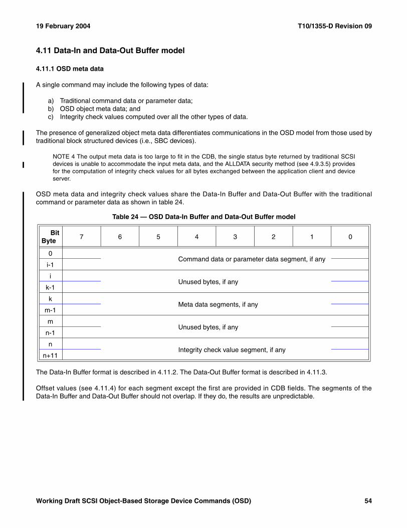
19 February 2004 T10/1355-D Revision 09
4.11 Data-In and Data-Out Buffer model
4.11.1 OSD meta data
A single command may include the following types of data:
a) Traditional command data or parameter data;b) OSD object meta data; andc) Integrity check values computed over all the other types of data.
The presence of generalized object meta data differentiates communications in the OSD model from those used bytraditional block structured devices (i.e., SBC devices).
NOTE 4 The output meta data is too large to fit in the CDB, the single status byte returned by traditional SCSIdevices is unable to accommodate the input meta data, and the ALLDATA security method (see 4.9.3.5) providesfor the computation of integrity check values for all bytes exchanged between the application client and deviceserver.
OSD meta data and integrity check values share the Data-In Buffer and Data-Out Buffer with the traditionalcommand or parameter data as shown in table 24.
The Data-In Buffer format is described in 4.11.2. The Data-Out Buffer format is described in 4.11.3.
Offset values (see 4.11.4) for each segment except the first are provided in CDB fields. The segments of theData-In Buffer and Data-Out Buffer should not overlap. If they do, the results are unpredictable.
Table 24 — OSD Data-In Buffer and Data-Out Buffer model
BitByte
7 6 5 4 3 2 1 0
0Command data or parameter data segment, if any
i-1
iUnused bytes, if any
k-1
kMeta data segments, if any
m-1
mUnused bytes, if any
n-1
nIntegrity check value segment, if any
n+11
Working Draft SCSI Object-Based Storage Device Commands (OSD) 54
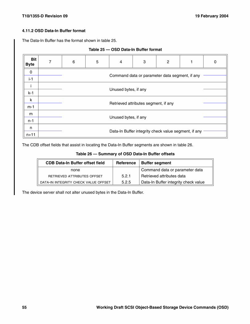
T10/1355-D Revision 09 19 February 2004
4.11.2 OSD Data-In Buffer format
The Data-In Buffer has the format shown in table 25.
The CDB offset fields that assist in locating the Data-In Buffer segments are shown in table 26.
The device server shall not alter unused bytes in the Data-In Buffer.
Table 25 — OSD Data-In Buffer format
BitByte
7 6 5 4 3 2 1 0
0Command data or parameter data segment, if any
i-1
iUnused bytes, if any
k-1
kRetrieved attributes segment, if any
m-1
mUnused bytes, if any
n-1
nData-In Buffer integrity check value segment, if any
n+11
Table 26 — Summary of OSD Data-In Buffer offsets
CDB Data-In Buffer offset field Reference Buffer segment
none Command data or parameter data
RETRIEVED ATTRIBUTES OFFSET 5.2.1 Retrieved attributes data
DATA-IN INTEGRITY CHECK VALUE OFFSET 5.2.5 Data-In Buffer integrity check value
55 Working Draft SCSI Object-Based Storage Device Commands (OSD)
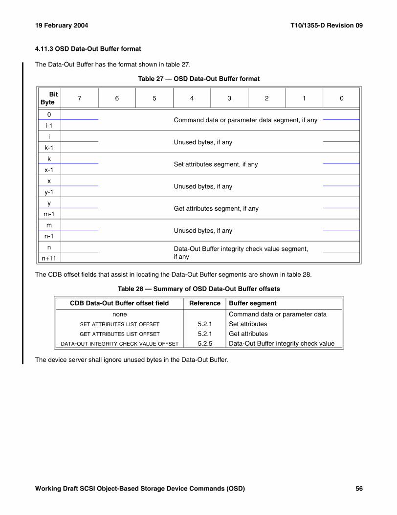
19 February 2004 T10/1355-D Revision 09
4.11.3 OSD Data-Out Buffer format
The Data-Out Buffer has the format shown in table 27.
The CDB offset fields that assist in locating the Data-Out Buffer segments are shown in table 28.
The device server shall ignore unused bytes in the Data-Out Buffer.
Table 27 — OSD Data-Out Buffer format
BitByte
7 6 5 4 3 2 1 0
0Command data or parameter data segment, if any
i-1
iUnused bytes, if any
k-1
kSet attributes segment, if any
x-1
xUnused bytes, if any
y-1
yGet attributes segment, if any
m-1
mUnused bytes, if any
n-1
n Data-Out Buffer integrity check value segment, if any
n+11
Table 28 — Summary of OSD Data-Out Buffer offsets
CDB Data-Out Buffer offset field Reference Buffer segment
none Command data or parameter data
SET ATTRIBUTES LIST OFFSET 5.2.1 Set attributes
GET ATTRIBUTES LIST OFFSET 5.2.1 Get attributes
DATA-OUT INTEGRITY CHECK VALUE OFFSET 5.2.5 Data-Out Buffer integrity check value
Working Draft SCSI Object-Based Storage Device Commands (OSD) 56
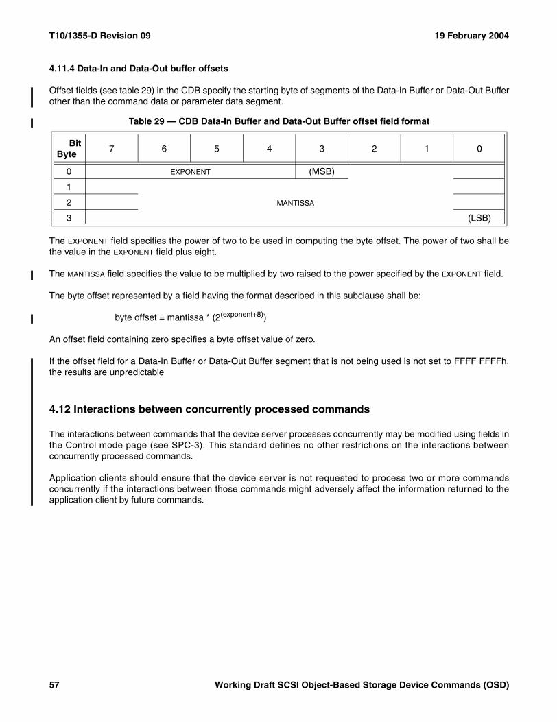
T10/1355-D Revision 09 19 February 2004
4.11.4 Data-In and Data-Out buffer offsets
Offset fields (see table 29) in the CDB specify the starting byte of segments of the Data-In Buffer or Data-Out Bufferother than the command data or parameter data segment.
The EXPONENT field specifies the power of two to be used in computing the byte offset. The power of two shall bethe value in the EXPONENT field plus eight.
The MANTISSA field specifies the value to be multiplied by two raised to the power specified by the EXPONENT field.
The byte offset represented by a field having the format described in this subclause shall be:
byte offset = mantissa * (2(exponent+8))
An offset field containing zero specifies a byte offset value of zero.
If the offset field for a Data-In Buffer or Data-Out Buffer segment that is not being used is not set to FFFF FFFFh,the results are unpredictable
4.12 Interactions between concurrently processed commands
The interactions between commands that the device server processes concurrently may be modified using fields inthe Control mode page (see SPC-3). This standard defines no other restrictions on the interactions betweenconcurrently processed commands.
Application clients should ensure that the device server is not requested to process two or more commandsconcurrently if the interactions between those commands might adversely affect the information returned to theapplication client by future commands.
Table 29 — CDB Data-In Buffer and Data-Out Buffer offset field format
BitByte
7 6 5 4 3 2 1 0
0 EXPONENT (MSB)
1
MANTISSA2
3 (LSB)
57 Working Draft SCSI Object-Based Storage Device Commands (OSD)
19 February 2004 T10/1355-D Revision 09
4.13 Error reporting
OSD logical units shall use descriptor format sense data (see SPC-3) to report all errors.
All sense data returned by OSD device servers shall include the OSD object identification sense data descriptor(see SPC-3) to identify the OSD object in which the reported error was detected.
If it is possible to identify a specific byte or range of bytes within a user object as being associated with an error, theinformation sense data descriptor (see SPC-3) shall be included in the sense data with the INFORMATION field set tothe byte associated with the error or the first byte in the range of bytes associated with the error.
If a READ command (see 6.14) attempts to read bytes both before and beyond a user object’s logical length, thecommand-specific information sense data descriptor (see SPC-3) shall be included in the sense data with theCOMMAND-SPECIFIC INFORMATION field set to the number of bytes transferred before the user object’s logical lengthwas reached.
If the CMDRSP security method or the ALLDATA security method (see 4.9.3) is used to process the command, thesense data shall include the OSD response integrity check value sense data descriptor (see SPC-3) with theRESPONSE INTEGRITY CHECK VALUE field containing an integrity check value (see 4.9.7) that is computed asdescribed in 4.9.3.4.
NOTE 5 If the status is not CHECK CONDITION and no sense data is transferred, the response integrity checkvalue is returned in the response integrity check value attribute in the Current Command attributes page (see7.1.2.24).
The OSD CDB is very large. To reduce uncertainty in determining errors in CDB field settings or in parameter data,any sense data having the sense key set to ILLEGAL REQUEST should include the sense key specific sense datadescriptor (see SPC-3) with the field pointer sense key specific data.
Errors other than those defined in this standard may be reported as needed. The sense data shall include theappropriate sense key and additional sense code (see SPC-3) to identify the condition.
Errors may occur after the command has completed. For such errors, SPC-3 defines a deferred error reportingmechanism.
4.14 Linked commands
OSD device servers shall not support linked commands.
4.15 Reservations
The access enabled or access disabled condition determines when an application client may store or retrieve userdata on all or part of the medium. Access may be restricted for read command functions, write command functions,or both. This attribute may be controlled by an external mechanism or by the PERSISTENT RESERVE INcommand and PERSISTENT RESERVE OUT command (see SPC-3). The OSD logical unit shall not support theRESERVE command or the RELEASE command.
The credential-based system defined by the OSD security model (see 4.9) provides access controls that are moreappropriate to an OBSD (see 3.1.26) than persistent reservations. Use of persistent reservations is permitted onlyif use of the OSD security model is not activated. If the security method in effect for the root or any partition in the
Working Draft SCSI Object-Based Storage Device Commands (OSD) 58
T10/1355-D Revision 09 19 February 2004
OSD logical unit is not zero, the PERSISTENT RESERVE IN command and PERSISTENT RESERVE OUTcommand shall be treated as invalid commands (see SPC-3).
If a persistent reservation is in effect or any registrations are established when the security method in effect for theroot or any partition changes from the NOSEC security method to any other security method, the persistent reser-vation, if any, shall be released and all registrations shall be unregistered. A unit attention condition (see SAM-3)shall be established for every initiator port associated with a registered I_T nexus. The sense key shall be set toUNIT ATTENTION and the additional sense code shall be set to RESERVATIONS RELEASED.
The PERSISTENT RESERVE IN command and the PERSISTENT RESERVE OUT command define how differenttypes of restricted access may be achieved, and to whom the access is restricted. This subclause describes theinteraction of the application client that requested the reservation, and the other application clients.
An application client uses reservations to gain a level of exclusivity in access to all or part of the medium for itself oranother application client. It is expected that the reservation is retained until released. The device server ensuresthat the application client with the reservation is able to access the reserved media within the operating parametersestablished by that application client.
Reservation restrictions are placed on commands as a result of access qualifiers associated with the type of reser-vation. The details of commands that are allowed under what types of reservations are described in table 30.
Commands from initiator ports holding a reservation should complete normally. The behavior of commands fromregistered initiator ports when a registrants only or all registrants persistent reservation is present is specified intable 30.
A command shall be checked for reservation conflicts before the task containing that command enters the enabledtask state.
59 Working Draft SCSI Object-Based Storage Device Commands (OSD)
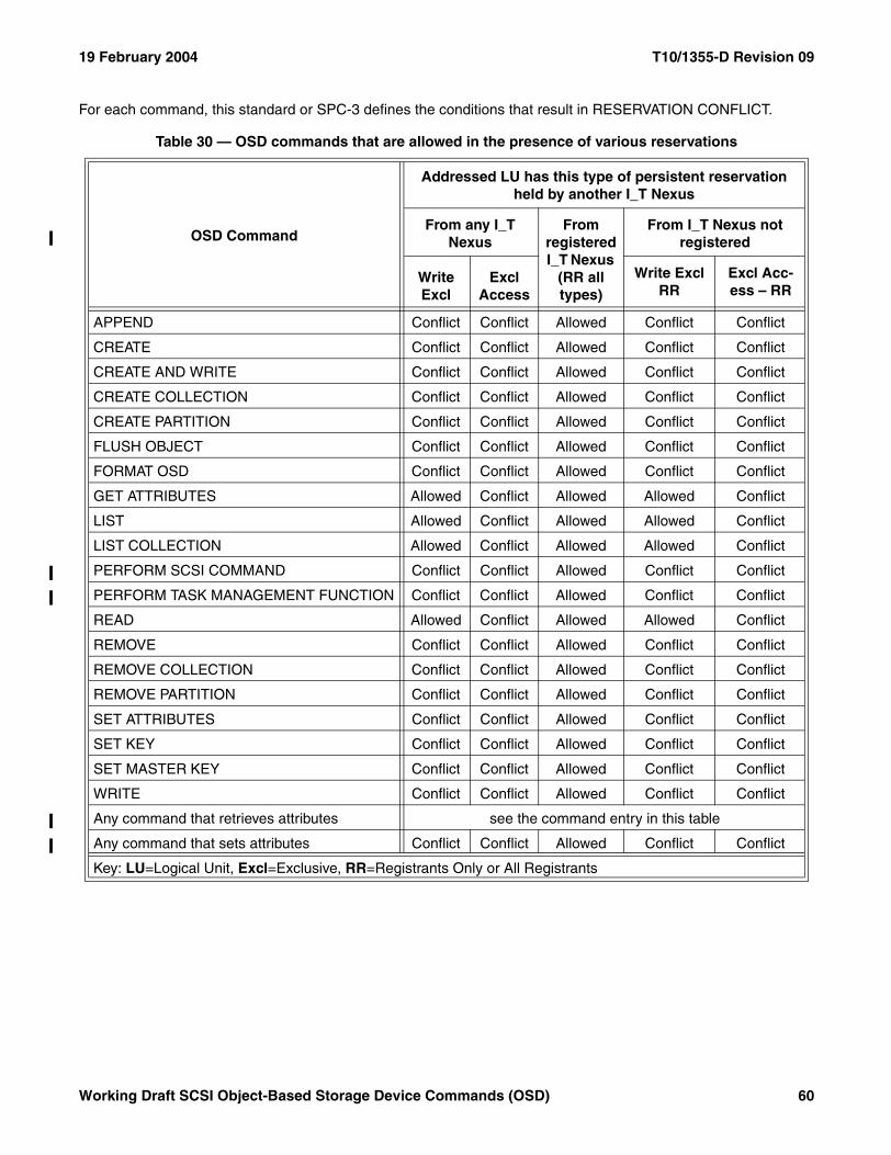
19 February 2004 T10/1355-D Revision 09
For each command, this standard or SPC-3 defines the conditions that result in RESERVATION CONFLICT.
Table 30 — OSD commands that are allowed in the presence of various reservations
OSD Command
Addressed LU has this type of persistent reservation held by another I_T Nexus
From any I_T Nexus
From registered I_T Nexus
(RR all types)
From I_T Nexus not registered
Write Excl
Excl Access
Write Excl RR
Excl Acc- ess – RR
APPEND Conflict Conflict Allowed Conflict Conflict
CREATE Conflict Conflict Allowed Conflict Conflict
CREATE AND WRITE Conflict Conflict Allowed Conflict Conflict
CREATE COLLECTION Conflict Conflict Allowed Conflict Conflict
CREATE PARTITION Conflict Conflict Allowed Conflict Conflict
FLUSH OBJECT Conflict Conflict Allowed Conflict Conflict
FORMAT OSD Conflict Conflict Allowed Conflict Conflict
GET ATTRIBUTES Allowed Conflict Allowed Allowed Conflict
LIST Allowed Conflict Allowed Allowed Conflict
LIST COLLECTION Allowed Conflict Allowed Allowed Conflict
PERFORM SCSI COMMAND Conflict Conflict Allowed Conflict Conflict
PERFORM TASK MANAGEMENT FUNCTION Conflict Conflict Allowed Conflict Conflict
READ Allowed Conflict Allowed Allowed Conflict
REMOVE Conflict Conflict Allowed Conflict Conflict
REMOVE COLLECTION Conflict Conflict Allowed Conflict Conflict
REMOVE PARTITION Conflict Conflict Allowed Conflict Conflict
SET ATTRIBUTES Conflict Conflict Allowed Conflict Conflict
SET KEY Conflict Conflict Allowed Conflict Conflict
SET MASTER KEY Conflict Conflict Allowed Conflict Conflict
WRITE Conflict Conflict Allowed Conflict Conflict
Any command that retrieves attributes see the command entry in this table
Any command that sets attributes Conflict Conflict Allowed Conflict Conflict
Key: LU=Logical Unit, Excl=Exclusive, RR=Registrants Only or All Registrants
Working Draft SCSI Object-Based Storage Device Commands (OSD) 60
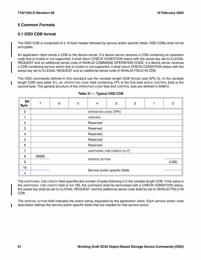
T10/1355-D Revision 09 19 February 2004
5 Common Formats
5.1 OSD CDB format
The OSD CDB is comprised of a 10-byte header followed by service action specific fields. OSD CDBs shall not beencrypted.
An application client sends a CDB to the device server. If a device server receives a CDB containing an operationcode that is invalid or not supported, it shall return CHECK CONDITION status with the sense key set to ILLEGALREQUEST and an additional sense code of INVALID COMMAND OPERATION CODE. If a device server receivesa CDB containing service action that is invalid or not supported, it shall return CHECK CONDITION status with thesense key set to ILLEGAL REQUEST and an additional sense code of INVALID FIELD IN CDB.
The OSD commands defined in this standard use the variable length CDB format (see SPC-3). In the variablelength CDB (see table 31), an OPERATION CODE field containing 7Fh is the first byte and a CONTROL byte is thesecond byte. The general structure of the OPERATION CODE field and CONTROL byte are defined in SAM-3.
The ADDITIONAL CDB LENGTH field specifies the number of bytes following it in the variable length CDB. If the value inthe ADDITIONAL CDB LENGTH field is not 166, the command shall be terminated with a CHECK CONDITION status,the sense key shall be set to ILLEGAL REQUEST, and the additional sense code shall be set to INVALID FIELD INCDB.
The SERVICE ACTION field indicates the action being requested by the application client. Each service action codedescription defines the service action specific fields that are needed for that service action.
Table 31 — Typical OSD CDB
BitByte
7 6 5 4 3 2 1 0
0 OPERATION CODE (7Fh)
1 CONTROL
2 Reserved
3 Reserved
4 Reserved
5 Reserved
6 Reserved
7 ADDITIONAL CDB LENGTH (n-7)
8 (MSB)SERVICE ACTION
9 (LSB)
10Service action specific fields
n
61 Working Draft SCSI Object-Based Storage Device Commands (OSD)
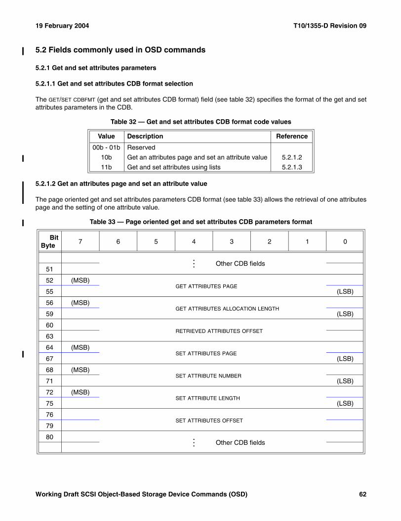
19 February 2004 T10/1355-D Revision 09
5.2 Fields commonly used in OSD commands
5.2.1 Get and set attributes parameters
5.2.1.1 Get and set attributes CDB format selection
The GET/SET CDBFMT (get and set attributes CDB format) field (see table 32) specifies the format of the get and setattributes parameters in the CDB.
5.2.1.2 Get an attributes page and set an attribute value
The page oriented get and set attributes parameters CDB format (see table 33) allows the retrieval of one attributespage and the setting of one attribute value.
Table 32 — Get and set attributes CDB format code values
Value Description Reference
00b - 01b Reserved
10b Get an attributes page and set an attribute value 5.2.1.2
11b Get and set attributes using lists 5.2.1.3
Table 33 — Page oriented get and set attributes CDB parameters format
BitByte
7 6 5 4 3 2 1 0
... Other CDB fields51
52 (MSB)GET ATTRIBUTES PAGE
55 (LSB)
56 (MSB)GET ATTRIBUTES ALLOCATION LENGTH
59 (LSB)
60RETRIEVED ATTRIBUTES OFFSET
63
64 (MSB)SET ATTRIBUTES PAGE
67 (LSB)
68 (MSB)SET ATTRIBUTE NUMBER
71 (LSB)
72 (MSB)SET ATTRIBUTE LENGTH
75 (LSB)
76SET ATTRIBUTES OFFSET
79
80 ... Other CDB fields
Working Draft SCSI Object-Based Storage Device Commands (OSD) 62
T10/1355-D Revision 09 19 February 2004
The GET ATTRIBUTES PAGE field specifies the attributes page number (see 7.1.2) to be retrieved. Zero specifies thatno attributes page is to be retrieved.
The GET ATTRIBUTES ALLOCATION LENGTH field specifies the number of bytes allocated to receive retrieved attributespage.
If the get attributes allocation length is not sufficient to accommodate all bytes in the specified attributes page, thetransfer of attributes data shall be truncated at the specified get attributes allocation length; this shall not beconsidered to be an error. If get attributes data is truncated, all the get attributes data that is transferred shall betransferred as if no error occurred (i.e., length fields in the transferred get attributes data shall not be modified toreflect the truncation).
The RETRIEVED ATTRIBUTES OFFSET field specifies the byte offset of the first Data-In Buffer byte to contain theretrieved attributes page. The format of the RETRIEVED ATTRIBUTES OFFSET field is described in 4.11.4. The format ofthe Data-In Buffer when attributes are being retrieved is described in 4.11.2.
The SET ATTRIBUTES PAGE field and SET ATTRIBUTE NUMBER field specify one attribute value to be set. A zero in theSET ATTRIBUTES PAGE field specifies that no attribute value is to be set.
The SET ATTRIBUTE LENGTH field specifies the number of bytes in the attribute being set.
The SET ATTRIBUTES OFFSET field specifies the byte offset of the first Data-Out Buffer byte containing the value ofthe attribute to be set. The format of the SET ATTRIBUTES OFFSET field is described in 4.11.4. The format of theData-Out Buffer when attributes are being set is described in 4.11.3.
If the set attributes page is non-zero and setting of the attribute specified by the SET ATTRIBUTES PAGE field and SET
ATTRIBUTE NUMBER field is not prohibited, the attribute length shall be set to the value in the SET ATTRIBUTE LENGTH
field and the value of the attribute shall be set to the contents of the Data-Out Buffer starting at the byte offsetspecified by the SET ATTRIBUTES OFFSET field and continuing for the number of bytes specified by the SET ATTRIBUTE
LENGTH field. If the attribute specified by the SET ATTRIBUTES PAGE field and SET ATTRIBUTE NUMBER field has notbeen defined previously setting it shall not be considered an error.
If setting an attribute value causes the value in the used capacity attribute in the Partition Information attributespage (see 7.1.2.9) to exceed the value in the capacity quota attribute in the Partition Quotas attributes page (see7.1.2.13), then a quota error shall be generated (see 4.8.2). The quota testing principles described in 4.8.3 apply tothe testing of the capacity quota.
63 Working Draft SCSI Object-Based Storage Device Commands (OSD)
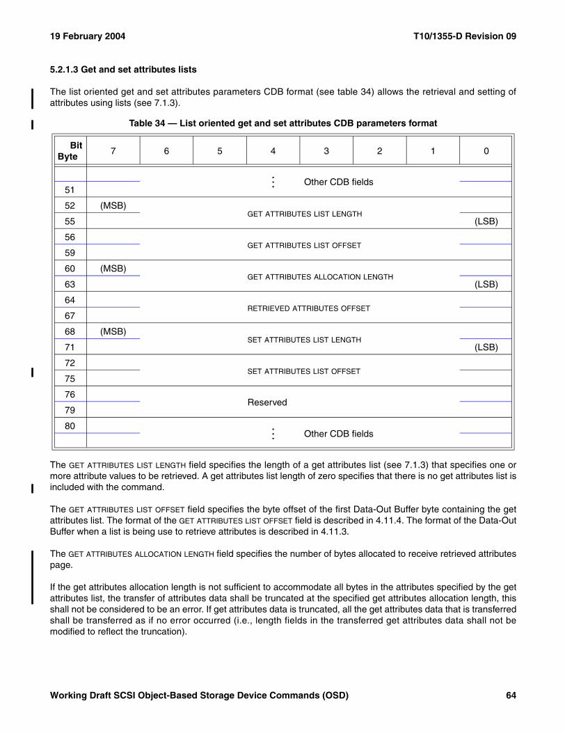
19 February 2004 T10/1355-D Revision 09
5.2.1.3 Get and set attributes lists
The list oriented get and set attributes parameters CDB format (see table 34) allows the retrieval and setting ofattributes using lists (see 7.1.3).
The GET ATTRIBUTES LIST LENGTH field specifies the length of a get attributes list (see 7.1.3) that specifies one ormore attribute values to be retrieved. A get attributes list length of zero specifies that there is no get attributes list isincluded with the command.
The GET ATTRIBUTES LIST OFFSET field specifies the byte offset of the first Data-Out Buffer byte containing the getattributes list. The format of the GET ATTRIBUTES LIST OFFSET field is described in 4.11.4. The format of the Data-OutBuffer when a list is being use to retrieve attributes is described in 4.11.3.
The GET ATTRIBUTES ALLOCATION LENGTH field specifies the number of bytes allocated to receive retrieved attributespage.
If the get attributes allocation length is not sufficient to accommodate all bytes in the attributes specified by the getattributes list, the transfer of attributes data shall be truncated at the specified get attributes allocation length, thisshall not be considered to be an error. If get attributes data is truncated, all the get attributes data that is transferredshall be transferred as if no error occurred (i.e., length fields in the transferred get attributes data shall not bemodified to reflect the truncation).
Table 34 — List oriented get and set attributes CDB parameters format
BitByte
7 6 5 4 3 2 1 0
... Other CDB fields51
52 (MSB)GET ATTRIBUTES LIST LENGTH
55 (LSB)
56GET ATTRIBUTES LIST OFFSET
59
60 (MSB)GET ATTRIBUTES ALLOCATION LENGTH
63 (LSB)
64RETRIEVED ATTRIBUTES OFFSET
67
68 (MSB)SET ATTRIBUTES LIST LENGTH
71 (LSB)
72SET ATTRIBUTES LIST OFFSET
75
76Reserved
79
80 ... Other CDB fields
Working Draft SCSI Object-Based Storage Device Commands (OSD) 64
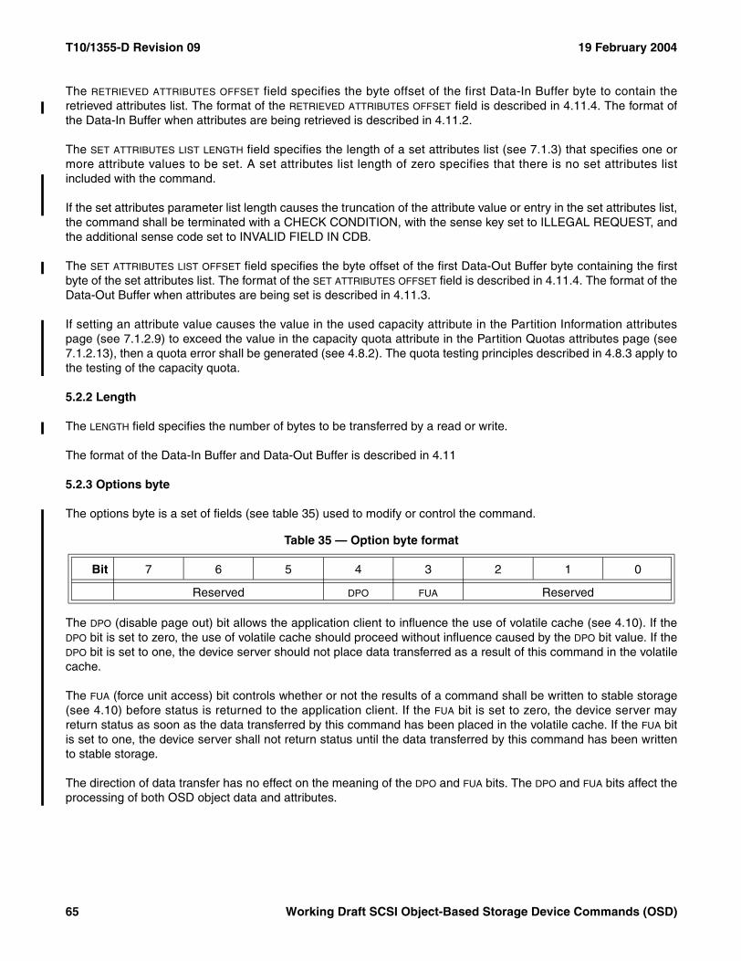
T10/1355-D Revision 09 19 February 2004
The RETRIEVED ATTRIBUTES OFFSET field specifies the byte offset of the first Data-In Buffer byte to contain theretrieved attributes list. The format of the RETRIEVED ATTRIBUTES OFFSET field is described in 4.11.4. The format ofthe Data-In Buffer when attributes are being retrieved is described in 4.11.2.
The SET ATTRIBUTES LIST LENGTH field specifies the length of a set attributes list (see 7.1.3) that specifies one ormore attribute values to be set. A set attributes list length of zero specifies that there is no set attributes listincluded with the command.
If the set attributes parameter list length causes the truncation of the attribute value or entry in the set attributes list,the command shall be terminated with a CHECK CONDITION, with the sense key set to ILLEGAL REQUEST, andthe additional sense code set to INVALID FIELD IN CDB.
The SET ATTRIBUTES LIST OFFSET field specifies the byte offset of the first Data-Out Buffer byte containing the firstbyte of the set attributes list. The format of the SET ATTRIBUTES OFFSET field is described in 4.11.4. The format of theData-Out Buffer when attributes are being set is described in 4.11.3.
If setting an attribute value causes the value in the used capacity attribute in the Partition Information attributespage (see 7.1.2.9) to exceed the value in the capacity quota attribute in the Partition Quotas attributes page (see7.1.2.13), then a quota error shall be generated (see 4.8.2). The quota testing principles described in 4.8.3 apply tothe testing of the capacity quota.
5.2.2 Length
The LENGTH field specifies the number of bytes to be transferred by a read or write.
The format of the Data-In Buffer and Data-Out Buffer is described in 4.11
5.2.3 Options byte
The options byte is a set of fields (see table 35) used to modify or control the command.
The DPO (disable page out) bit allows the application client to influence the use of volatile cache (see 4.10). If theDPO bit is set to zero, the use of volatile cache should proceed without influence caused by the DPO bit value. If theDPO bit is set to one, the device server should not place data transferred as a result of this command in the volatilecache.
The FUA (force unit access) bit controls whether or not the results of a command shall be written to stable storage(see 4.10) before status is returned to the application client. If the FUA bit is set to zero, the device server mayreturn status as soon as the data transferred by this command has been placed in the volatile cache. If the FUA bitis set to one, the device server shall not return status until the data transferred by this command has been writtento stable storage.
The direction of data transfer has no effect on the meaning of the DPO and FUA bits. The DPO and FUA bits affect theprocessing of both OSD object data and attributes.
Table 35 — Option byte format
Bit 7 6 5 4 3 2 1 0
Reserved DPO FUA Reserved
65 Working Draft SCSI Object-Based Storage Device Commands (OSD)
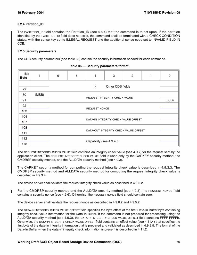
19 February 2004 T10/1355-D Revision 09
5.2.4 Partition_ID
The PARTITION_ID field contains the Partition_ID (see 4.6.4) that the command is to act upon. If the partitionidentified by the PARTITION_ID field does not exist, the command shall be terminated with a CHECK CONDITIONstatus, with the sense key set to ILLEGAL REQUEST and the additional sense code set to INVALID FIELD INCDB.
5.2.5 Security parameters
The CDB security parameters (see table 36) contain the security information needed for each command.
The REQUEST INTEGRITY CHECK VALUE field contains an integrity check value (see 4.9.7) for the request sent by theapplication client. The REQUEST INTEGRITY CHECK VALUE field is used only by the CAPKEY security method, theCMDRSP security method, and the ALLDATA security method (see 4.9.3).
The CAPKEY security method for computing the request integrity check value is described in 4.9.3.3. TheCMDRSP security method and ALLDATA security method for computing the request integrity check value isdescribed in 4.9.3.4.
The device server shall validate the request integrity check value as described in 4.9.5.2.
For the CMDRSP security method and the ALLDATA security method (see 4.9.3), the REQUEST NONCE fieldcontains a security nonce (see 4.9.6). Otherwise, the REQUEST NONCE field should contain zero.
The device server shall validate the request nonce as described in 4.9.6.2 and 4.9.5.2.
The DATA-IN INTEGRITY CHECK VALUE OFFSET field specifies the byte offset of the first Data-In Buffer byte containingintegrity check value information for the Data-In Buffer. If the command is not prepared for processing using theALLDATA security method (see 4.9.3), the DATA-IN INTEGRITY CHECK VALUE OFFSET field contains FFFF FFFFh.Otherwise, the DATA-IN INTEGRITY CHECK VALUE OFFSET field contains an offset value (see 4.11.4) that specifies thefirst byte of the data-in integrity information that is prepared and validated as described in 4.9.3.5. The format of theData-In Buffer when the data-in integrity check information is present is described in 4.11.2.
Table 36 — Security parameters format
BitByte
7 6 5 4 3 2 1 0
... Other CDB fields79
80 (MSB)REQUEST INTEGRITY CHECK VALUE
91 (LSB)
92REQUEST NONCE
103
104DATA-IN INTEGRITY CHECK VALUE OFFSET
107
108DATA-OUT INTEGRITY CHECK VALUE OFFSET
111
112
Capability (see 4.9.4.3)
173
Working Draft SCSI Object-Based Storage Device Commands (OSD) 66
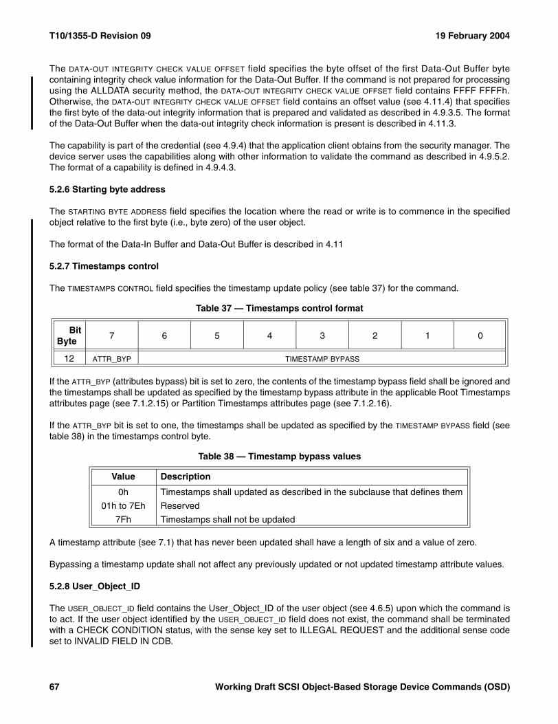
T10/1355-D Revision 09 19 February 2004
The DATA-OUT INTEGRITY CHECK VALUE OFFSET field specifies the byte offset of the first Data-Out Buffer bytecontaining integrity check value information for the Data-Out Buffer. If the command is not prepared for processingusing the ALLDATA security method, the DATA-OUT INTEGRITY CHECK VALUE OFFSET field contains FFFF FFFFh.Otherwise, the DATA-OUT INTEGRITY CHECK VALUE OFFSET field contains an offset value (see 4.11.4) that specifiesthe first byte of the data-out integrity information that is prepared and validated as described in 4.9.3.5. The formatof the Data-Out Buffer when the data-out integrity check information is present is described in 4.11.3.
The capability is part of the credential (see 4.9.4) that the application client obtains from the security manager. Thedevice server uses the capabilities along with other information to validate the command as described in 4.9.5.2.The format of a capability is defined in 4.9.4.3.
5.2.6 Starting byte address
The STARTING BYTE ADDRESS field specifies the location where the read or write is to commence in the specifiedobject relative to the first byte (i.e., byte zero) of the user object.
The format of the Data-In Buffer and Data-Out Buffer is described in 4.11
5.2.7 Timestamps control
The TIMESTAMPS CONTROL field specifies the timestamp update policy (see table 37) for the command.
If the ATTR_BYP (attributes bypass) bit is set to zero, the contents of the timestamp bypass field shall be ignored andthe timestamps shall be updated as specified by the timestamp bypass attribute in the applicable Root Timestampsattributes page (see 7.1.2.15) or Partition Timestamps attributes page (see 7.1.2.16).
If the ATTR_BYP bit is set to one, the timestamps shall be updated as specified by the TIMESTAMP BYPASS field (seetable 38) in the timestamps control byte.
A timestamp attribute (see 7.1) that has never been updated shall have a length of six and a value of zero.
Bypassing a timestamp update shall not affect any previously updated or not updated timestamp attribute values.
5.2.8 User_Object_ID
The USER_OBJECT_ID field contains the User_Object_ID of the user object (see 4.6.5) upon which the command isto act. If the user object identified by the USER_OBJECT_ID field does not exist, the command shall be terminatedwith a CHECK CONDITION status, with the sense key set to ILLEGAL REQUEST and the additional sense codeset to INVALID FIELD IN CDB.
Table 37 — Timestamps control format
BitByte
7 6 5 4 3 2 1 0
12 ATTR_BYP TIMESTAMP BYPASS
Table 38 — Timestamp bypass values
Value Description
0h Timestamps shall updated as described in the subclause that defines them
01h to 7Eh Reserved
7Fh Timestamps shall not be updated
67 Working Draft SCSI Object-Based Storage Device Commands (OSD)
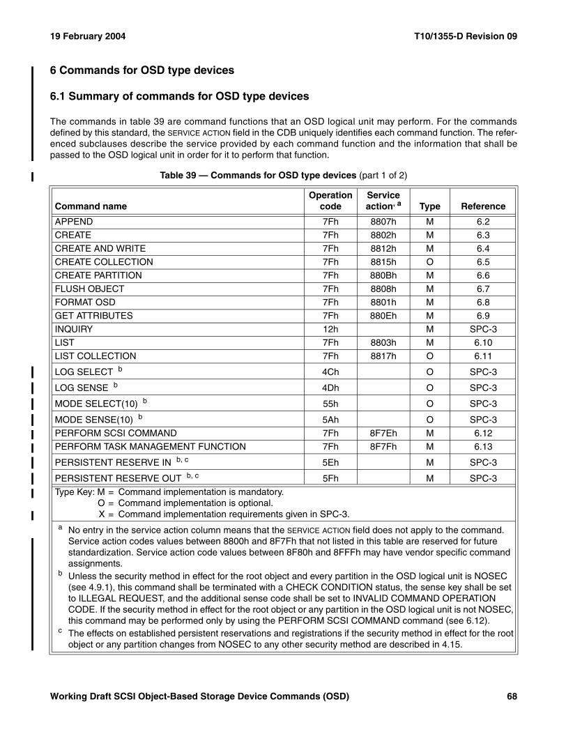
19 February 2004 T10/1355-D Revision 09
6 Commands for OSD type devices
6.1 Summary of commands for OSD type devices
The commands in table 39 are command functions that an OSD logical unit may perform. For the commandsdefined by this standard, the SERVICE ACTION field in the CDB uniquely identifies each command function. The refer-enced subclauses describe the service provided by each command function and the information that shall bepassed to the OSD logical unit in order for it to perform that function.
Table 39 — Commands for OSD type devices (part 1 of 2)
Command nameOperation
codeService action, a Type Reference
APPEND 7Fh 8807h M 6.2
CREATE 7Fh 8802h M 6.3
CREATE AND WRITE 7Fh 8812h M 6.4
CREATE COLLECTION 7Fh 8815h O 6.5
CREATE PARTITION 7Fh 880Bh M 6.6
FLUSH OBJECT 7Fh 8808h M 6.7
FORMAT OSD 7Fh 8801h M 6.8
GET ATTRIBUTES 7Fh 880Eh M 6.9
INQUIRY 12h M SPC-3
LIST 7Fh 8803h M 6.10
LIST COLLECTION 7Fh 8817h O 6.11
LOG SELECT b 4Ch O SPC-3
LOG SENSE b 4Dh O SPC-3
MODE SELECT(10) b 55h O SPC-3
MODE SENSE(10) b 5Ah O SPC-3
PERFORM SCSI COMMAND 7Fh 8F7Eh M 6.12
PERFORM TASK MANAGEMENT FUNCTION 7Fh 8F7Fh M 6.13
PERSISTENT RESERVE IN b, c 5Eh M SPC-3
PERSISTENT RESERVE OUT b, c 5Fh M SPC-3
Type Key: M = Command implementation is mandatory.O = Command implementation is optional.X = Command implementation requirements given in SPC-3.
a No entry in the service action column means that the SERVICE ACTION field does not apply to the command. Service action codes values between 8800h and 8F7Fh that not listed in this table are reserved for future standardization. Service action code values between 8F80h and 8FFFh may have vendor specific command assignments.
b Unless the security method in effect for the root object and every partition in the OSD logical unit is NOSEC (see 4.9.1), this command shall be terminated with a CHECK CONDITION status, the sense key shall be set to ILLEGAL REQUEST, and the additional sense code shall be set to INVALID COMMAND OPERATION CODE. If the security method in effect for the root object or any partition in the OSD logical unit is not NOSEC, this command may be performed only by using the PERFORM SCSI COMMAND command (see 6.12).
c The effects on established persistent reservations and registrations if the security method in effect for the root object or any partition changes from NOSEC to any other security method are described in 4.15.
Working Draft SCSI Object-Based Storage Device Commands (OSD) 68
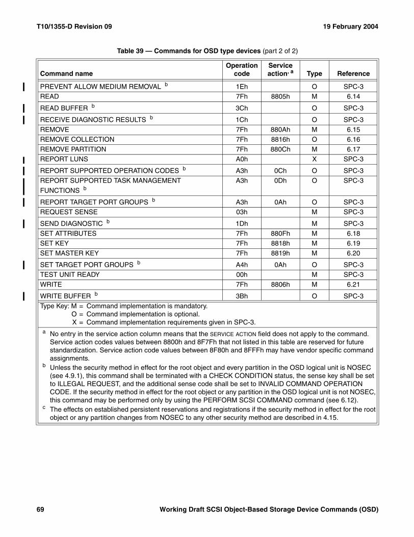
T10/1355-D Revision 09 19 February 2004
PREVENT ALLOW MEDIUM REMOVAL b 1Eh O SPC-3
READ 7Fh 8805h M 6.14
READ BUFFER b 3Ch O SPC-3
RECEIVE DIAGNOSTIC RESULTS b 1Ch O SPC-3
REMOVE 7Fh 880Ah M 6.15
REMOVE COLLECTION 7Fh 8816h O 6.16
REMOVE PARTITION 7Fh 880Ch M 6.17
REPORT LUNS A0h X SPC-3
REPORT SUPPORTED OPERATION CODES b A3h 0Ch O SPC-3
REPORT SUPPORTED TASK MANAGEMENT
FUNCTIONS bA3h 0Dh O SPC-3
REPORT TARGET PORT GROUPS b A3h 0Ah O SPC-3
REQUEST SENSE 03h M SPC-3
SEND DIAGNOSTIC b 1Dh M SPC-3
SET ATTRIBUTES 7Fh 880Fh M 6.18
SET KEY 7Fh 8818h M 6.19
SET MASTER KEY 7Fh 8819h M 6.20
SET TARGET PORT GROUPS b A4h 0Ah O SPC-3
TEST UNIT READY 00h M SPC-3
WRITE 7Fh 8806h M 6.21
WRITE BUFFER b 3Bh O SPC-3
Table 39 — Commands for OSD type devices (part 2 of 2)
Command nameOperation
codeService action, a Type Reference
Type Key: M = Command implementation is mandatory.O = Command implementation is optional.X = Command implementation requirements given in SPC-3.
a No entry in the service action column means that the SERVICE ACTION field does not apply to the command. Service action codes values between 8800h and 8F7Fh that not listed in this table are reserved for future standardization. Service action code values between 8F80h and 8FFFh may have vendor specific command assignments.
b Unless the security method in effect for the root object and every partition in the OSD logical unit is NOSEC (see 4.9.1), this command shall be terminated with a CHECK CONDITION status, the sense key shall be set to ILLEGAL REQUEST, and the additional sense code shall be set to INVALID COMMAND OPERATION CODE. If the security method in effect for the root object or any partition in the OSD logical unit is not NOSEC, this command may be performed only by using the PERFORM SCSI COMMAND command (see 6.12).
c The effects on established persistent reservations and registrations if the security method in effect for the root object or any partition changes from NOSEC to any other security method are described in 4.15.
69 Working Draft SCSI Object-Based Storage Device Commands (OSD)
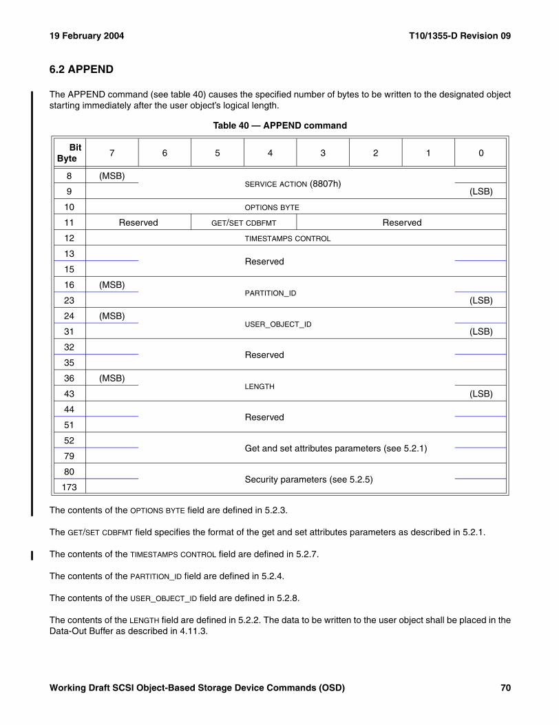
19 February 2004 T10/1355-D Revision 09
6.2 APPEND
The APPEND command (see table 40) causes the specified number of bytes to be written to the designated objectstarting immediately after the user object’s logical length.
The contents of the OPTIONS BYTE field are defined in 5.2.3.
The GET/SET CDBFMT field specifies the format of the get and set attributes parameters as described in 5.2.1.
The contents of the TIMESTAMPS CONTROL field are defined in 5.2.7.
The contents of the PARTITION_ID field are defined in 5.2.4.
The contents of the USER_OBJECT_ID field are defined in 5.2.8.
The contents of the LENGTH field are defined in 5.2.2. The data to be written to the user object shall be placed in theData-Out Buffer as described in 4.11.3.
Table 40 — APPEND command
BitByte
7 6 5 4 3 2 1 0
8 (MSB)SERVICE ACTION (8807h)
9 (LSB)
10 OPTIONS BYTE
11 Reserved GET/SET CDBFMT Reserved
12 TIMESTAMPS CONTROL
13Reserved
15
16 (MSB)PARTITION_ID
23 (LSB)
24 (MSB)USER_OBJECT_ID
31 (LSB)
32Reserved
35
36 (MSB)LENGTH
43 (LSB)
44Reserved
51
52 Get and set attributes parameters (see 5.2.1)
79
80Security parameters (see 5.2.5)
173
Working Draft SCSI Object-Based Storage Device Commands (OSD) 70
T10/1355-D Revision 09 19 February 2004
The get and set attributes parameters are defined in 5.2.1. The format of the Data-In Buffer and Data-Out Bufferwhen attributes are being retrieved or set is described in 4.11.
The security parameters are defined in 5.2.5.
If an APPEND command causes the value in the user object logical length attribute in the User Object Informationattributes page (see 7.1.2.11) to exceed the value in the maximum user object length attribute in the The COLLEC-TIONS PER USER OBJECT field contains the value of the collections per user object attribute. (see ), then a quota errorshall be generated (see 4.8.2). The quota testing principles described in 4.8.3 apply to the testing of the maximumuser object length quota.
If an APPEND command causes the value in the used capacity attribute in the Partition Information attributes page(see 7.1.2.9) to exceed the value in the capacity quota attribute in the Partition Quotas attributes page (see7.1.2.13), then a quota error shall be generated (see 4.8.2). The quota testing principles described in 4.8.3 apply tothe testing of the capacity quota.
71 Working Draft SCSI Object-Based Storage Device Commands (OSD)
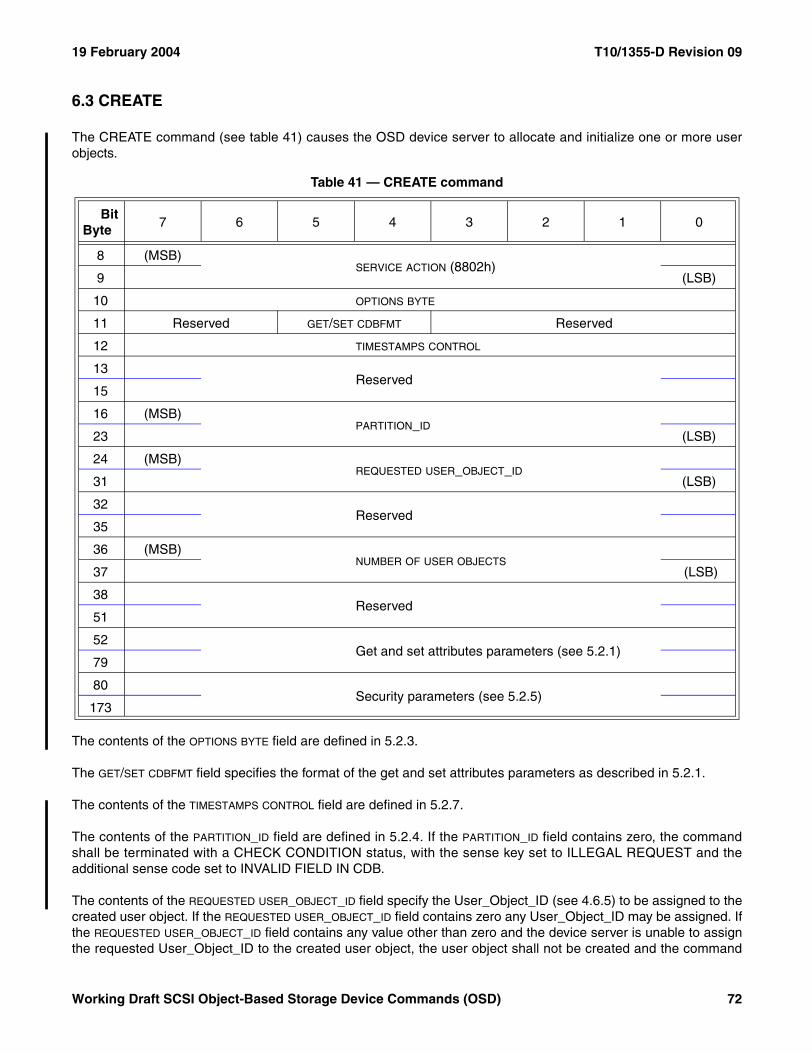
19 February 2004 T10/1355-D Revision 09
6.3 CREATE
The CREATE command (see table 41) causes the OSD device server to allocate and initialize one or more userobjects.
The contents of the OPTIONS BYTE field are defined in 5.2.3.
The GET/SET CDBFMT field specifies the format of the get and set attributes parameters as described in 5.2.1.
The contents of the TIMESTAMPS CONTROL field are defined in 5.2.7.
The contents of the PARTITION_ID field are defined in 5.2.4. If the PARTITION_ID field contains zero, the commandshall be terminated with a CHECK CONDITION status, with the sense key set to ILLEGAL REQUEST and theadditional sense code set to INVALID FIELD IN CDB.
The contents of the REQUESTED USER_OBJECT_ID field specify the User_Object_ID (see 4.6.5) to be assigned to thecreated user object. If the REQUESTED USER_OBJECT_ID field contains zero any User_Object_ID may be assigned. Ifthe REQUESTED USER_OBJECT_ID field contains any value other than zero and the device server is unable to assignthe requested User_Object_ID to the created user object, the user object shall not be created and the command
Table 41 — CREATE command
BitByte
7 6 5 4 3 2 1 0
8 (MSB)SERVICE ACTION (8802h)
9 (LSB)
10 OPTIONS BYTE
11 Reserved GET/SET CDBFMT Reserved
12 TIMESTAMPS CONTROL
13Reserved
15
16 (MSB)PARTITION_ID
23 (LSB)
24 (MSB)REQUESTED USER_OBJECT_ID
31 (LSB)
32Reserved
35
36 (MSB)NUMBER OF USER OBJECTS
37 (LSB)
38Reserved
51
52 Get and set attributes parameters (see 5.2.1)
79
80Security parameters (see 5.2.5)
173
Working Draft SCSI Object-Based Storage Device Commands (OSD) 72
T10/1355-D Revision 09 19 February 2004
shall be terminated with a CHECK CONDITION status, with the sense key set to ILLEGAL REQUEST and theadditional sense code set to INVALID FIELD IN CDB.
Within a partition, the device server shall not allow:
a) The same User_Object_ID to be associated with more than one user object at any point in time; orb) A User_Object_ID to have the same value as any assigned Collection_Object_ID.
The NUMBER OF USER OBJECTS field specifies the number of user objects to be created. If the NUMBER OF USER
OBJECTS field contains zero or one, one user object shall be created. Otherwise:
a) The number of user objects created shall equal the value in the NUMBER OF USER OBJECTS field;b) The user objects created shall be assigned consecutive valued User_Object_IDs; andc) The lowest valued User_Object_ID shall be placed in the created User_Object_ID attribute of the Current
Command attributes page (see 7.1.2.24).
If the NUMBER OF USER OBJECTS field contains a value that is greater than one and the requested User_Object_ID isnot zero, the command shall be terminated with a CHECK CONDITION status, with the sense key set to ILLEGALREQUEST and the additional sense code set to INVALID FIELD IN CDB.
The command shall be terminated with a CHECK CONDITION status, with the sense key set to ILLEGALREQUEST and the additional sense code set to INVALID FIELD IN CDB if:
a) If the NUMBER OF USER OBJECT field contains a value that is greater than one;b) The GET/SET CDBFMT field contains 10b; andc) The GET ATTRIBUTES PAGE field (see 5.2.1.2) contains a value other than FFFF FFFEh (i.e., the Current
Command attributes page).
The get and set attributes parameters are defined in 5.2.1. The format of the Data-In Buffer and Data-Out Bufferwhen attributes are being retrieved or set is described in 4.11.
If the get and set attributes parameters request the retrieval of attributes from pages other than the CurrentCommand attributes page, the attributes for every created user object shall be returned using list type Fh (see7.1.3).
The security parameters are defined in 5.2.5.
If a CREATE command causes the sum of the number of collections and the number of user objects in the partitionto exceed the value in the object count attribute in the Partition Quotas attributes page (see 7.1.2.13), then a quotaerror shall be generated (see 4.8.2). The quota testing principles described in 4.8.3 apply to the testing of theobject count quota.
73 Working Draft SCSI Object-Based Storage Device Commands (OSD)
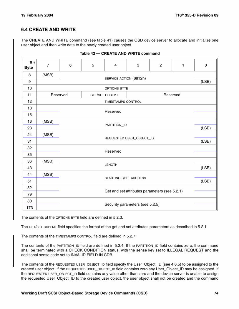
19 February 2004 T10/1355-D Revision 09
6.4 CREATE AND WRITE
The CREATE AND WRITE command (see table 41) causes the OSD device server to allocate and initialize oneuser object and then write data to the newly created user object.
The contents of the OPTIONS BYTE field are defined in 5.2.3.
The GET/SET CDBFMT field specifies the format of the get and set attributes parameters as described in 5.2.1.
The contents of the TIMESTAMPS CONTROL field are defined in 5.2.7.
The contents of the PARTITION_ID field are defined in 5.2.4. If the PARTITION_ID field contains zero, the commandshall be terminated with a CHECK CONDITION status, with the sense key set to ILLEGAL REQUEST and theadditional sense code set to INVALID FIELD IN CDB.
The contents of the REQUESTED USER_OBJECT_ID field specify the User_Object_ID (see 4.6.5) to be assigned to thecreated user object. If the REQUESTED USER_OBJECT_ID field contains zero any User_Object_ID may be assigned. Ifthe REQUESTED USER_OBJECT_ID field contains any value other than zero and the device server is unable to assignthe requested User_Object_ID to the created user object, the user object shall not be created and the command
Table 42 — CREATE AND WRITE command
BitByte
7 6 5 4 3 2 1 0
8 (MSB)SERVICE ACTION (8812h)
9 (LSB)
10 OPTIONS BYTE
11 Reserved GET/SET CDBFMT Reserved
12 TIMESTAMPS CONTROL
13Reserved
15
16 (MSB)PARTITION_ID
23 (LSB)
24 (MSB)REQUESTED USER_OBJECT_ID
31 (LSB)
32Reserved
35
36 (MSB)LENGTH
43 (LSB)
44 (MSB)STARTING BYTE ADDRESS
51 (LSB)
52 Get and set attributes parameters (see 5.2.1)
79
80Security parameters (see 5.2.5)
173
Working Draft SCSI Object-Based Storage Device Commands (OSD) 74
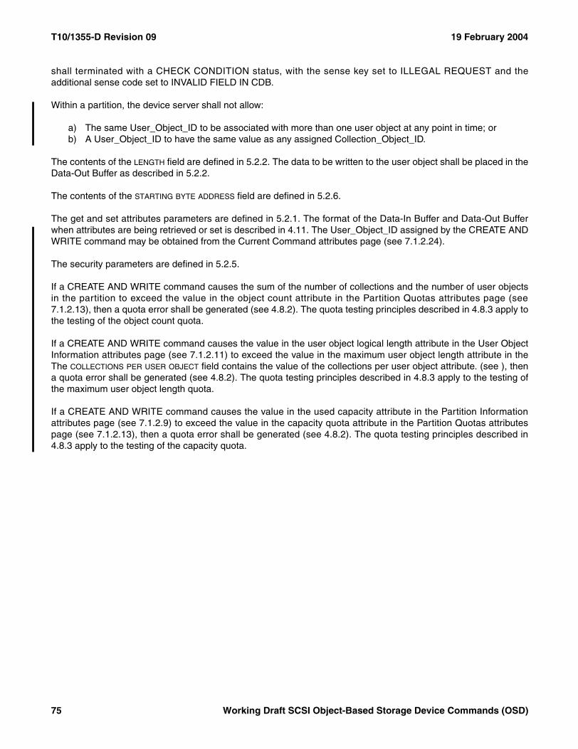
T10/1355-D Revision 09 19 February 2004
shall terminated with a CHECK CONDITION status, with the sense key set to ILLEGAL REQUEST and theadditional sense code set to INVALID FIELD IN CDB.
Within a partition, the device server shall not allow:
a) The same User_Object_ID to be associated with more than one user object at any point in time; orb) A User_Object_ID to have the same value as any assigned Collection_Object_ID.
The contents of the LENGTH field are defined in 5.2.2. The data to be written to the user object shall be placed in theData-Out Buffer as described in 5.2.2.
The contents of the STARTING BYTE ADDRESS field are defined in 5.2.6.
The get and set attributes parameters are defined in 5.2.1. The format of the Data-In Buffer and Data-Out Bufferwhen attributes are being retrieved or set is described in 4.11. The User_Object_ID assigned by the CREATE ANDWRITE command may be obtained from the Current Command attributes page (see 7.1.2.24).
The security parameters are defined in 5.2.5.
If a CREATE AND WRITE command causes the sum of the number of collections and the number of user objectsin the partition to exceed the value in the object count attribute in the Partition Quotas attributes page (see7.1.2.13), then a quota error shall be generated (see 4.8.2). The quota testing principles described in 4.8.3 apply tothe testing of the object count quota.
If a CREATE AND WRITE command causes the value in the user object logical length attribute in the User ObjectInformation attributes page (see 7.1.2.11) to exceed the value in the maximum user object length attribute in theThe COLLECTIONS PER USER OBJECT field contains the value of the collections per user object attribute. (see ), thena quota error shall be generated (see 4.8.2). The quota testing principles described in 4.8.3 apply to the testing ofthe maximum user object length quota.
If a CREATE AND WRITE command causes the value in the used capacity attribute in the Partition Informationattributes page (see 7.1.2.9) to exceed the value in the capacity quota attribute in the Partition Quotas attributespage (see 7.1.2.13), then a quota error shall be generated (see 4.8.2). The quota testing principles described in4.8.3 apply to the testing of the capacity quota.
75 Working Draft SCSI Object-Based Storage Device Commands (OSD)
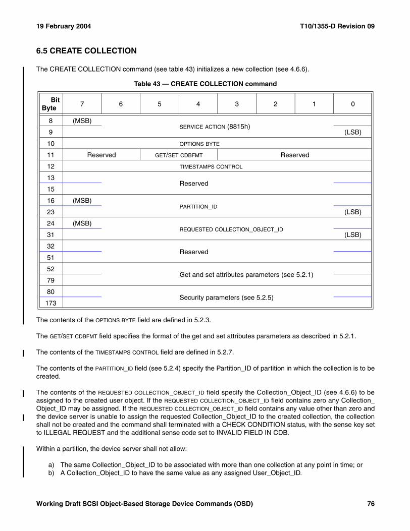
19 February 2004 T10/1355-D Revision 09
6.5 CREATE COLLECTION
The CREATE COLLECTION command (see table 43) initializes a new collection (see 4.6.6).
The contents of the OPTIONS BYTE field are defined in 5.2.3.
The GET/SET CDBFMT field specifies the format of the get and set attributes parameters as described in 5.2.1.
The contents of the TIMESTAMPS CONTROL field are defined in 5.2.7.
The contents of the PARTITION_ID field (see 5.2.4) specify the Partition_ID of partition in which the collection is to becreated.
The contents of the REQUESTED COLLECTION_OBJECT_ID field specify the Collection_Object_ID (see 4.6.6) to beassigned to the created user object. If the REQUESTED COLLECTION_OBJECT_ID field contains zero any Collection_Object_ID may be assigned. If the REQUESTED COLLECTION_OBJECT_ID field contains any value other than zero andthe device server is unable to assign the requested Collection_Object_ID to the created collection, the collectionshall not be created and the command shall terminated with a CHECK CONDITION status, with the sense key setto ILLEGAL REQUEST and the additional sense code set to INVALID FIELD IN CDB.
Within a partition, the device server shall not allow:
a) The same Collection_Object_ID to be associated with more than one collection at any point in time; orb) A Collection_Object_ID to have the same value as any assigned User_Object_ID.
Table 43 — CREATE COLLECTION command
BitByte
7 6 5 4 3 2 1 0
8 (MSB)SERVICE ACTION (8815h)
9 (LSB)
10 OPTIONS BYTE
11 Reserved GET/SET CDBFMT Reserved
12 TIMESTAMPS CONTROL
13Reserved
15
16 (MSB)PARTITION_ID
23 (LSB)
24 (MSB)REQUESTED COLLECTION_OBJECT_ID
31 (LSB)
32Reserved
51
52 Get and set attributes parameters (see 5.2.1)
79
80Security parameters (see 5.2.5)
173
Working Draft SCSI Object-Based Storage Device Commands (OSD) 76
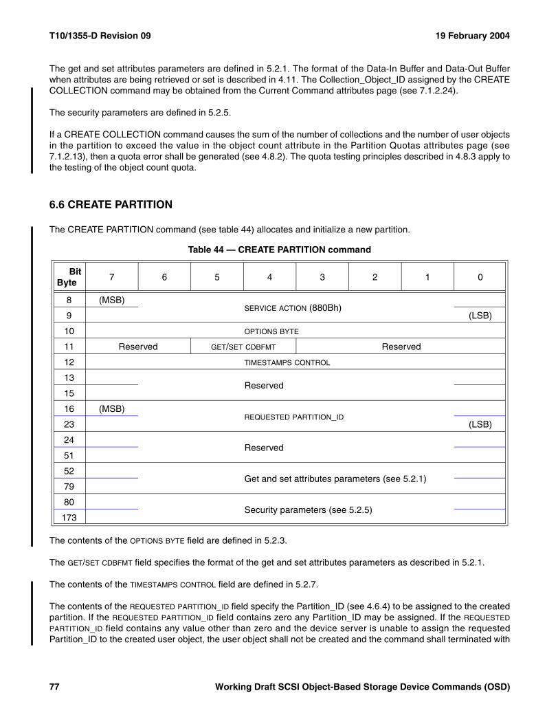
T10/1355-D Revision 09 19 February 2004
The get and set attributes parameters are defined in 5.2.1. The format of the Data-In Buffer and Data-Out Bufferwhen attributes are being retrieved or set is described in 4.11. The Collection_Object_ID assigned by the CREATECOLLECTION command may be obtained from the Current Command attributes page (see 7.1.2.24).
The security parameters are defined in 5.2.5.
If a CREATE COLLECTION command causes the sum of the number of collections and the number of user objectsin the partition to exceed the value in the object count attribute in the Partition Quotas attributes page (see7.1.2.13), then a quota error shall be generated (see 4.8.2). The quota testing principles described in 4.8.3 apply tothe testing of the object count quota.
6.6 CREATE PARTITION
The CREATE PARTITION command (see table 44) allocates and initialize a new partition.
The contents of the OPTIONS BYTE field are defined in 5.2.3.
The GET/SET CDBFMT field specifies the format of the get and set attributes parameters as described in 5.2.1.
The contents of the TIMESTAMPS CONTROL field are defined in 5.2.7.
The contents of the REQUESTED PARTITION_ID field specify the Partition_ID (see 4.6.4) to be assigned to the createdpartition. If the REQUESTED PARTITION_ID field contains zero any Partition_ID may be assigned. If the REQUESTED
PARTITION_ID field contains any value other than zero and the device server is unable to assign the requestedPartition_ID to the created user object, the user object shall not be created and the command shall terminated with
Table 44 — CREATE PARTITION command
BitByte
7 6 5 4 3 2 1 0
8 (MSB)SERVICE ACTION (880Bh)
9 (LSB)
10 OPTIONS BYTE
11 Reserved GET/SET CDBFMT Reserved
12 TIMESTAMPS CONTROL
13Reserved
15
16 (MSB)REQUESTED PARTITION_ID
23 (LSB)
24Reserved
51
52 Get and set attributes parameters (see 5.2.1)
79
80Security parameters (see 5.2.5)
173
77 Working Draft SCSI Object-Based Storage Device Commands (OSD)
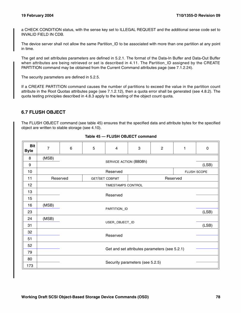
19 February 2004 T10/1355-D Revision 09
a CHECK CONDITION status, with the sense key set to ILLEGAL REQUEST and the additional sense code set toINVALID FIELD IN CDB.
The device server shall not allow the same Partition_ID to be associated with more than one partition at any pointin time.
The get and set attributes parameters are defined in 5.2.1. The format of the Data-In Buffer and Data-Out Bufferwhen attributes are being retrieved or set is described in 4.11. The Partition_ID assigned by the CREATEPARTITION command may be obtained from the Current Command attributes page (see 7.1.2.24).
The security parameters are defined in 5.2.5.
If a CREATE PARTITION command causes the number of partitions to exceed the value in the partition countattribute in the Root Quotas attributes page (see 7.1.2.12), then a quota error shall be generated (see 4.8.2). Thequota testing principles described in 4.8.3 apply to the testing of the object count quota.
6.7 FLUSH OBJECT
The FLUSH OBJECT command (see table 45) ensures that the specified data and attribute bytes for the specifiedobject are written to stable storage (see 4.10).
Table 45 — FLUSH OBJECT command
BitByte
7 6 5 4 3 2 1 0
8 (MSB)SERVICE ACTION (8808h)
9 (LSB)
10 Reserved FLUSH SCOPE
11 Reserved GET/SET CDBFMT Reserved
12 TIMESTAMPS CONTROL
13Reserved
15
16 (MSB)PARTITION_ID
23 (LSB)
24 (MSB)USER_OBJECT_ID
31 (LSB)
32Reserved
51
52 Get and set attributes parameters (see 5.2.1)
79
80Security parameters (see 5.2.5)
173
Working Draft SCSI Object-Based Storage Device Commands (OSD) 78
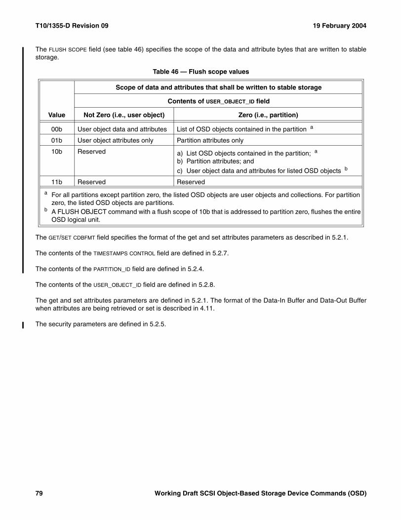
T10/1355-D Revision 09 19 February 2004
The FLUSH SCOPE field (see table 46) specifies the scope of the data and attribute bytes that are written to stablestorage.
The GET/SET CDBFMT field specifies the format of the get and set attributes parameters as described in 5.2.1.
The contents of the TIMESTAMPS CONTROL field are defined in 5.2.7.
The contents of the PARTITION_ID field are defined in 5.2.4.
The contents of the USER_OBJECT_ID field are defined in 5.2.8.
The get and set attributes parameters are defined in 5.2.1. The format of the Data-In Buffer and Data-Out Bufferwhen attributes are being retrieved or set is described in 4.11.
The security parameters are defined in 5.2.5.
Table 46 — Flush scope values
Value
Scope of data and attributes that shall be written to stable storage
Contents of USER_OBJECT_ID field
Not Zero (i.e., user object) Zero (i.e., partition)
00b User object data and attributes List of OSD objects contained in the partition a
01b User object attributes only Partition attributes only
10b Reserved a) List OSD objects contained in the partition; a
b) Partition attributes; and
c) User object data and attributes for listed OSD objects b
11b Reserved Reserved
a For all partitions except partition zero, the listed OSD objects are user objects and collections. For partition zero, the listed OSD objects are partitions.
b A FLUSH OBJECT command with a flush scope of 10b that is addressed to partition zero, flushes the entire OSD logical unit.
79 Working Draft SCSI Object-Based Storage Device Commands (OSD)
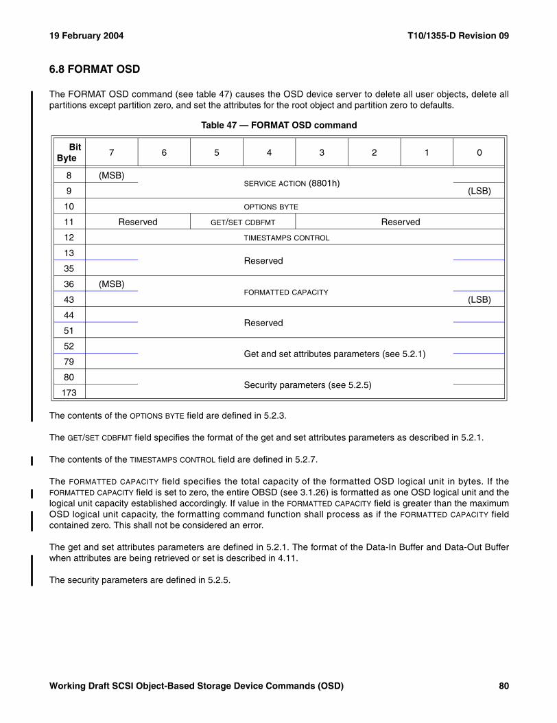
19 February 2004 T10/1355-D Revision 09
6.8 FORMAT OSD
The FORMAT OSD command (see table 47) causes the OSD device server to delete all user objects, delete allpartitions except partition zero, and set the attributes for the root object and partition zero to defaults.
The contents of the OPTIONS BYTE field are defined in 5.2.3.
The GET/SET CDBFMT field specifies the format of the get and set attributes parameters as described in 5.2.1.
The contents of the TIMESTAMPS CONTROL field are defined in 5.2.7.
The FORMATTED CAPACITY field specifies the total capacity of the formatted OSD logical unit in bytes. If theFORMATTED CAPACITY field is set to zero, the entire OBSD (see 3.1.26) is formatted as one OSD logical unit and thelogical unit capacity established accordingly. If value in the FORMATTED CAPACITY field is greater than the maximumOSD logical unit capacity, the formatting command function shall process as if the FORMATTED CAPACITY fieldcontained zero. This shall not be considered an error.
The get and set attributes parameters are defined in 5.2.1. The format of the Data-In Buffer and Data-Out Bufferwhen attributes are being retrieved or set is described in 4.11.
The security parameters are defined in 5.2.5.
Table 47 — FORMAT OSD command
BitByte
7 6 5 4 3 2 1 0
8 (MSB)SERVICE ACTION (8801h)
9 (LSB)
10 OPTIONS BYTE
11 Reserved GET/SET CDBFMT Reserved
12 TIMESTAMPS CONTROL
13Reserved
35
36 (MSB)FORMATTED CAPACITY
43 (LSB)
44Reserved
51
52 Get and set attributes parameters (see 5.2.1)
79
80Security parameters (see 5.2.5)
173
Working Draft SCSI Object-Based Storage Device Commands (OSD) 80
T10/1355-D Revision 09 19 February 2004
During the processing of a FORMAT OSD command, the device server shall respond to commands as follows:
a) In response to all commands except REQUEST SENSE and INQUIRY, the device server shall returnCHECK CONDITION status unless a reservation conflict exists, in which case RESERVATION CONFLICTstatus shall be returned;
b) In response to the INQUIRY command, the device server shall respond as specified in SPC-3; andc) In response to the REQUEST SENSE command, unless an error has occurred, the device server shall
return a sense key of NOT READY with the additional sense code set to LOGICAL UNIT NOT READYFORMAT IN PROGRESS, with the sense key specific bytes set for progress indication (as described inSPC-3).
Upon successful completion of a FORMAT OSD command, the OSD logical unit shall contain:
a) A root object;b) One partition OSD object for partition zero (i.e., the root partition);c) Zero collections;d) Zero user objects;e) Root object attributes and partition attributes as defined by this standard;f) Vendor specific additional root object attributes and partition attributes;g) Zero collection attributes;h) Zero user object attributes;i) Zero attributes pages with page numbers between P + 1 0000h and P + 1FFF FFFFh; andj) Zero attributes pages with page numbers between R + 1 0000h and R + 1FFF FFFFh.
Processing of the FORMAT OSD command shall not alter the master key, drive key, or any keys associatedpartition zero (see 4.9.8).
81 Working Draft SCSI Object-Based Storage Device Commands (OSD)
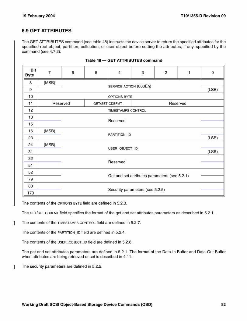
19 February 2004 T10/1355-D Revision 09
6.9 GET ATTRIBUTES
The GET ATTRIBUTES command (see table 48) instructs the device server to return the specified attributes for thespecified root object, partition, collection, or user object before setting the attributes, if any, specified by thecommand (see 4.7.2).
The contents of the OPTIONS BYTE field are defined in 5.2.3.
The GET/SET CDBFMT field specifies the format of the get and set attributes parameters as described in 5.2.1.
The contents of the TIMESTAMPS CONTROL field are defined in 5.2.7.
The contents of the PARTITION_ID field are defined in 5.2.4.
The contents of the USER_OBJECT_ID field are defined in 5.2.8.
The get and set attributes parameters are defined in 5.2.1. The format of the Data-In Buffer and Data-Out Bufferwhen attributes are being retrieved or set is described in 4.11.
The security parameters are defined in 5.2.5.
Table 48 — GET ATTRIBUTES command
BitByte
7 6 5 4 3 2 1 0
8 (MSB)SERVICE ACTION (880Eh)
9 (LSB)
10 OPTIONS BYTE
11 Reserved GET/SET CDBFMT Reserved
12 TIMESTAMPS CONTROL
13Reserved
15
16 (MSB)PARTITION_ID
23 (LSB)
24 (MSB)USER_OBJECT_ID
31 (LSB)
32Reserved
51
52 Get and set attributes parameters (see 5.2.1)
79
80Security parameters (see 5.2.5)
173
Working Draft SCSI Object-Based Storage Device Commands (OSD) 82
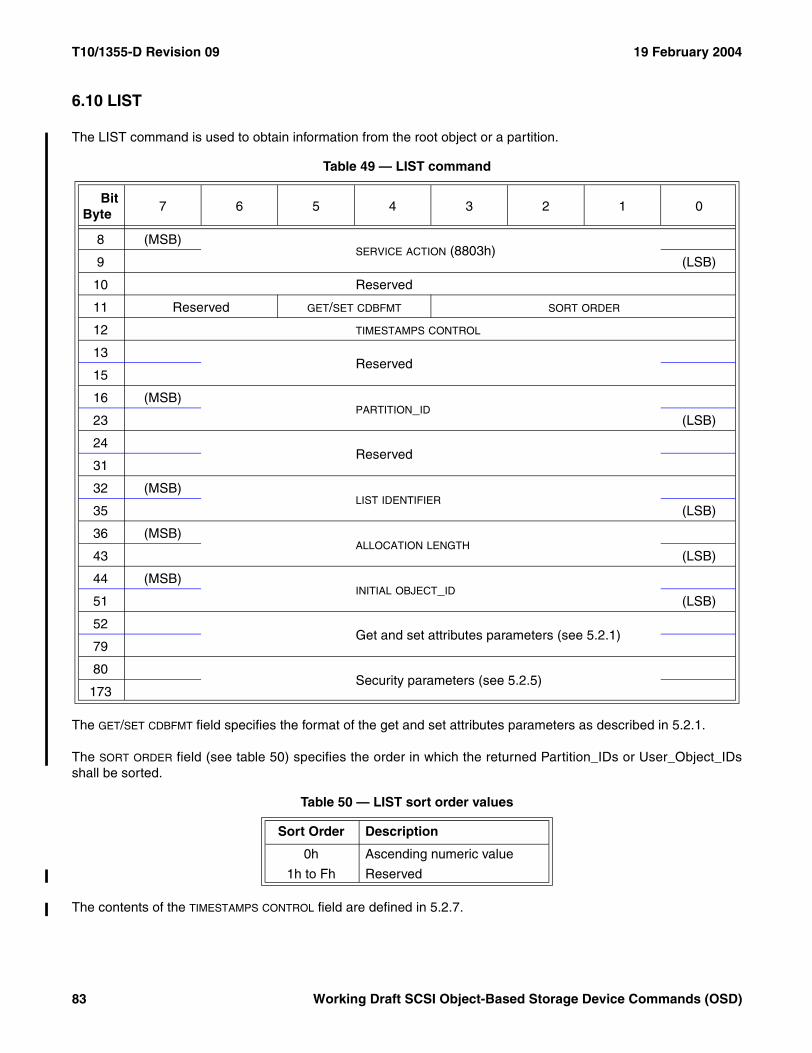
T10/1355-D Revision 09 19 February 2004
6.10 LIST
The LIST command is used to obtain information from the root object or a partition.
The GET/SET CDBFMT field specifies the format of the get and set attributes parameters as described in 5.2.1.
The SORT ORDER field (see table 50) specifies the order in which the returned Partition_IDs or User_Object_IDsshall be sorted.
The contents of the TIMESTAMPS CONTROL field are defined in 5.2.7.
Table 49 — LIST command
BitByte
7 6 5 4 3 2 1 0
8 (MSB)SERVICE ACTION (8803h)
9 (LSB)
10 Reserved
11 Reserved GET/SET CDBFMT SORT ORDER
12 TIMESTAMPS CONTROL
13Reserved
15
16 (MSB)PARTITION_ID
23 (LSB)
24Reserved
31
32 (MSB)LIST IDENTIFIER
35 (LSB)
36 (MSB)ALLOCATION LENGTH
43 (LSB)
44 (MSB)INITIAL OBJECT_ID
51 (LSB)
52 Get and set attributes parameters (see 5.2.1)
79
80Security parameters (see 5.2.5)
173
Table 50 — LIST sort order values
Sort Order Description
0h Ascending numeric value
1h to Fh Reserved
83 Working Draft SCSI Object-Based Storage Device Commands (OSD)
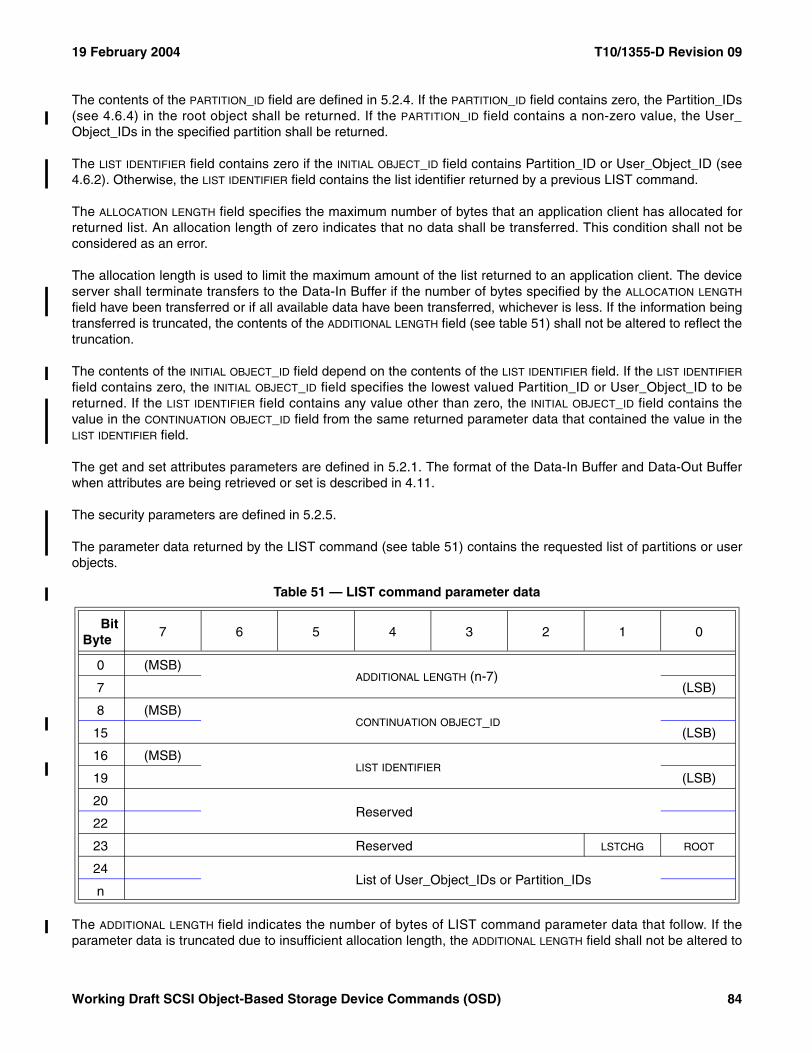
19 February 2004 T10/1355-D Revision 09
The contents of the PARTITION_ID field are defined in 5.2.4. If the PARTITION_ID field contains zero, the Partition_IDs(see 4.6.4) in the root object shall be returned. If the PARTITION_ID field contains a non-zero value, the User_Object_IDs in the specified partition shall be returned.
The LIST IDENTIFIER field contains zero if the INITIAL OBJECT_ID field contains Partition_ID or User_Object_ID (see4.6.2). Otherwise, the LIST IDENTIFIER field contains the list identifier returned by a previous LIST command.
The ALLOCATION LENGTH field specifies the maximum number of bytes that an application client has allocated forreturned list. An allocation length of zero indicates that no data shall be transferred. This condition shall not beconsidered as an error.
The allocation length is used to limit the maximum amount of the list returned to an application client. The deviceserver shall terminate transfers to the Data-In Buffer if the number of bytes specified by the ALLOCATION LENGTH
field have been transferred or if all available data have been transferred, whichever is less. If the information beingtransferred is truncated, the contents of the ADDITIONAL LENGTH field (see table 51) shall not be altered to reflect thetruncation.
The contents of the INITIAL OBJECT_ID field depend on the contents of the LIST IDENTIFIER field. If the LIST IDENTIFIER
field contains zero, the INITIAL OBJECT_ID field specifies the lowest valued Partition_ID or User_Object_ID to bereturned. If the LIST IDENTIFIER field contains any value other than zero, the INITIAL OBJECT_ID field contains thevalue in the CONTINUATION OBJECT_ID field from the same returned parameter data that contained the value in theLIST IDENTIFIER field.
The get and set attributes parameters are defined in 5.2.1. The format of the Data-In Buffer and Data-Out Bufferwhen attributes are being retrieved or set is described in 4.11.
The security parameters are defined in 5.2.5.
The parameter data returned by the LIST command (see table 51) contains the requested list of partitions or userobjects.
The ADDITIONAL LENGTH field indicates the number of bytes of LIST command parameter data that follow. If theparameter data is truncated due to insufficient allocation length, the ADDITIONAL LENGTH field shall not be altered to
Table 51 — LIST command parameter data
BitByte
7 6 5 4 3 2 1 0
0 (MSB)ADDITIONAL LENGTH (n-7)
7 (LSB)
8 (MSB)CONTINUATION OBJECT_ID
15 (LSB)
16 (MSB)LIST IDENTIFIER
19 (LSB)
20Reserved
22
23 Reserved LSTCHG ROOT
24List of User_Object_IDs or Partition_IDs
n
Working Draft SCSI Object-Based Storage Device Commands (OSD) 84
T10/1355-D Revision 09 19 February 2004
reflect the truncation (i.e., the additional length indicates the number of bytes that would follow if the allocationlength had been infinite). If the untruncated number of bytes that follow is greater than FFFF FFFF FFFF FFFFh theadditional length shall be set to FFFF FFFF FFFF FFFFh.
The CONTINUATION OBJECT_ID field provides information that may be used to continue a truncated list with a newLIST command. If the CONTINUATION OBJECT_ID field contains zero, the parameter data contains all of the list resultsand no further LIST commands are needed. If a new LIST command is sent to continue a truncated list, thecontents of the CONTINUATION OBJECT_ID field are copied to the INITIAL OBJECT_ID field of that command.
The LIST IDENTIFIER field contains an identifier required for continuing a truncated list in a new LIST command. If anew LIST command is sent to continue a truncated list, the contents of the LIST IDENTIFIER field are copied to theLIST IDENTIFIER field of that command.
A LSTCHG (list has changed) bit set to zero indicates that the entries in the list of OSD objects in the parameter datahas not changed since the first LIST command identified by the list identifier. A LSTCHG bit set to one indicates thatthe entries in the list of OSD objects in the parameter data has changed since the first LIST command identified bythe list identifier and that starting the list over at the original initial object_id may be necessary in order to obtain acomplete list.
A ROOT bit set to zero indicates that the OSD object IDs in the parameter data are from a partition and are User_Object_IDs. A ROOT set to one indicates that the OSD object IDs in the parameter data are from the root object andare Partition_IDs.
The list of User_Object_IDs or Partition_IDs contains one entry for each user object or partition identified by theLIST command. If the list is truncated based on allocation length, the truncation shall not occur in the middle of aUser_Object_ID or Partition_ID.
The list shall not contain Collection_Object_IDs. Lists of Collection_Object_IDs may be obtained using the LISTCOLLECTION command (see 6.11).
85 Working Draft SCSI Object-Based Storage Device Commands (OSD)
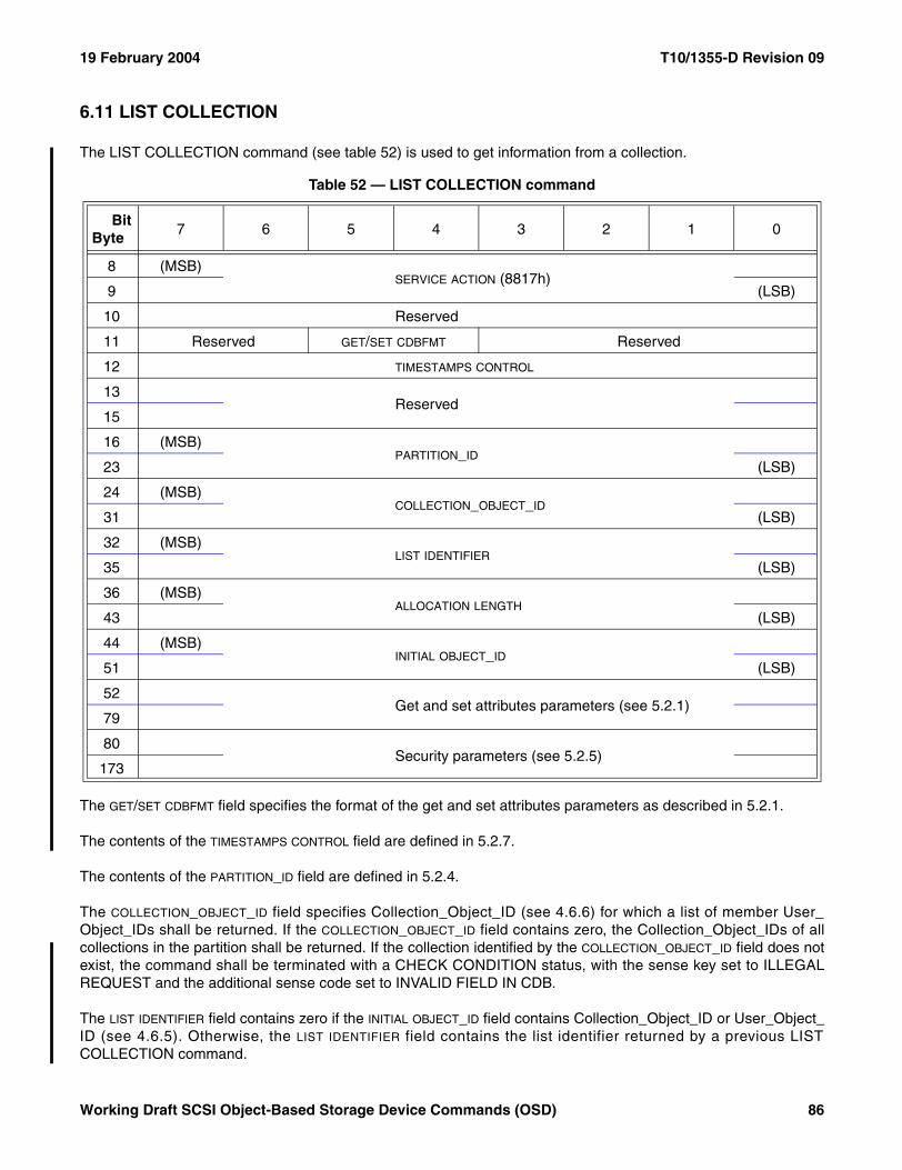
19 February 2004 T10/1355-D Revision 09
6.11 LIST COLLECTION
The LIST COLLECTION command (see table 52) is used to get information from a collection.
The GET/SET CDBFMT field specifies the format of the get and set attributes parameters as described in 5.2.1.
The contents of the TIMESTAMPS CONTROL field are defined in 5.2.7.
The contents of the PARTITION_ID field are defined in 5.2.4.
The COLLECTION_OBJECT_ID field specifies Collection_Object_ID (see 4.6.6) for which a list of member User_Object_IDs shall be returned. If the COLLECTION_OBJECT_ID field contains zero, the Collection_Object_IDs of allcollections in the partition shall be returned. If the collection identified by the COLLECTION_OBJECT_ID field does notexist, the command shall be terminated with a CHECK CONDITION status, with the sense key set to ILLEGALREQUEST and the additional sense code set to INVALID FIELD IN CDB.
The LIST IDENTIFIER field contains zero if the INITIAL OBJECT_ID field contains Collection_Object_ID or User_Object_ID (see 4.6.5). Otherwise, the LIST IDENTIFIER field contains the list identifier returned by a previous LISTCOLLECTION command.
Table 52 — LIST COLLECTION command
BitByte
7 6 5 4 3 2 1 0
8 (MSB)SERVICE ACTION (8817h)
9 (LSB)
10 Reserved
11 Reserved GET/SET CDBFMT Reserved
12 TIMESTAMPS CONTROL
13Reserved
15
16 (MSB)PARTITION_ID
23 (LSB)
24 (MSB)COLLECTION_OBJECT_ID
31 (LSB)
32 (MSB)LIST IDENTIFIER
35 (LSB)
36 (MSB)ALLOCATION LENGTH
43 (LSB)
44 (MSB)INITIAL OBJECT_ID
51 (LSB)
52 Get and set attributes parameters (see 5.2.1)
79
80Security parameters (see 5.2.5)
173
Working Draft SCSI Object-Based Storage Device Commands (OSD) 86
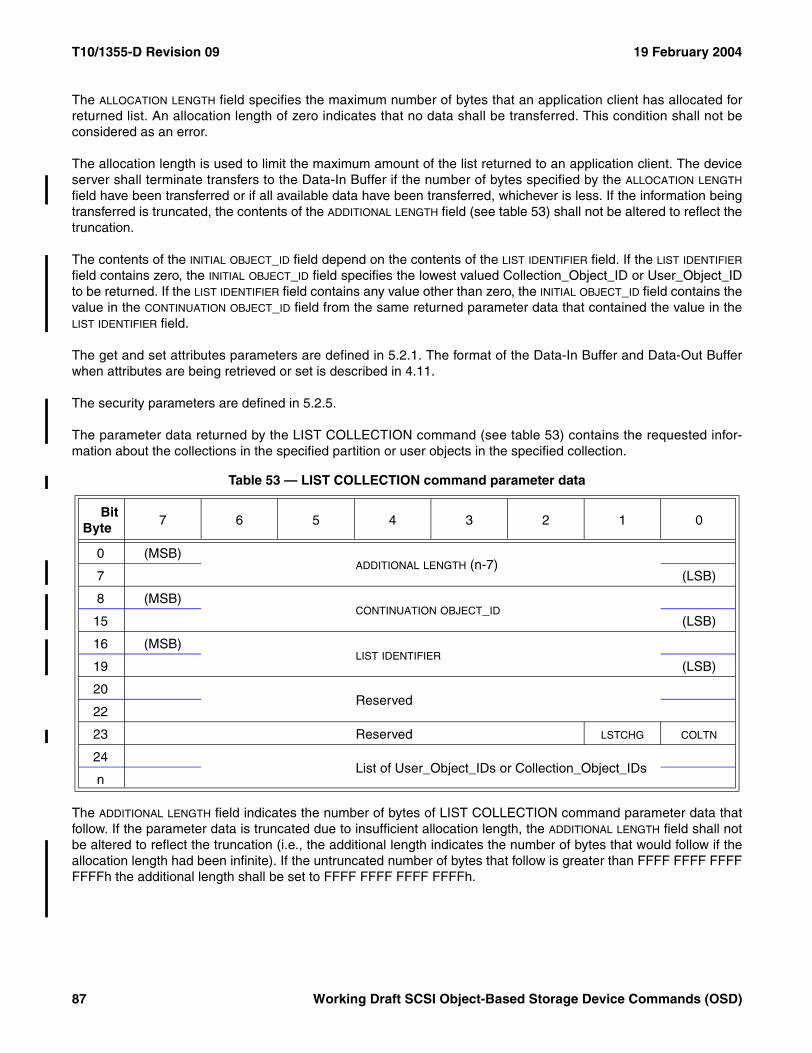
T10/1355-D Revision 09 19 February 2004
The ALLOCATION LENGTH field specifies the maximum number of bytes that an application client has allocated forreturned list. An allocation length of zero indicates that no data shall be transferred. This condition shall not beconsidered as an error.
The allocation length is used to limit the maximum amount of the list returned to an application client. The deviceserver shall terminate transfers to the Data-In Buffer if the number of bytes specified by the ALLOCATION LENGTH
field have been transferred or if all available data have been transferred, whichever is less. If the information beingtransferred is truncated, the contents of the ADDITIONAL LENGTH field (see table 53) shall not be altered to reflect thetruncation.
The contents of the INITIAL OBJECT_ID field depend on the contents of the LIST IDENTIFIER field. If the LIST IDENTIFIER
field contains zero, the INITIAL OBJECT_ID field specifies the lowest valued Collection_Object_ID or User_Object_IDto be returned. If the LIST IDENTIFIER field contains any value other than zero, the INITIAL OBJECT_ID field contains thevalue in the CONTINUATION OBJECT_ID field from the same returned parameter data that contained the value in theLIST IDENTIFIER field.
The get and set attributes parameters are defined in 5.2.1. The format of the Data-In Buffer and Data-Out Bufferwhen attributes are being retrieved or set is described in 4.11.
The security parameters are defined in 5.2.5.
The parameter data returned by the LIST COLLECTION command (see table 53) contains the requested infor-mation about the collections in the specified partition or user objects in the specified collection.
The ADDITIONAL LENGTH field indicates the number of bytes of LIST COLLECTION command parameter data thatfollow. If the parameter data is truncated due to insufficient allocation length, the ADDITIONAL LENGTH field shall notbe altered to reflect the truncation (i.e., the additional length indicates the number of bytes that would follow if theallocation length had been infinite). If the untruncated number of bytes that follow is greater than FFFF FFFF FFFFFFFFh the additional length shall be set to FFFF FFFF FFFF FFFFh.
Table 53 — LIST COLLECTION command parameter data
BitByte
7 6 5 4 3 2 1 0
0 (MSB)ADDITIONAL LENGTH (n-7)
7 (LSB)
8 (MSB)CONTINUATION OBJECT_ID
15 (LSB)
16 (MSB)LIST IDENTIFIER
19 (LSB)
20Reserved
22
23 Reserved LSTCHG COLTN
24List of User_Object_IDs or Collection_Object_IDs
n
87 Working Draft SCSI Object-Based Storage Device Commands (OSD)
19 February 2004 T10/1355-D Revision 09
The CONTINUATION OBJECT_ID field provides information that may be used to continue a truncated list with a newLIST COLLECTION command. If the CONTINUATION OBJECT_ID field contains zero, the parameter data contains allof the list results and no further LIST COLLECTION commands are needed. If a new LIST COLLECTIONcommand is sent to continue a truncated list, the contents of the CONTINUATION OBJECT_ID field are copied to theINITIAL OBJECT_ID field of that command.
The LIST IDENTIFIER field contains an identifier required for continuing a truncated list in a new LIST COLLECTIONcommand. If a new LIST COLLECTION command is sent to continue a truncated list, the contents of the LIST
IDENTIFIER field are copied to the LIST IDENTIFIER field of that command.
A LSTCHG (list has changed) bit set to zero indicates that the entries in the list of OSD objects in the parameter datahas not changed since the first LIST COLLECTION command identified by the list identifier. A LSTCHG bit set to oneindicates that the entries in the list of OSD objects in the parameter data has changed since the first LISTCOLLECTION command identified by the list identifier and that starting the list over at the original initial object_idmay be necessary in order to obtain a complete list.
A COLTN bit of zero indicates that the OSD object IDs in the parameter data are from a collection and are User_Object_IDs. A COLTN bit of one indicates that the OSD object IDs in the parameter data are from the partition andare Collection_Object_IDs.
The list of User_Object_IDs or Collection_Object_IDs contains one entry for each user object or collectionidentified by the LIST COLLECTION command. If the list is truncated based on allocation length, the truncationshall not occur in the middle of a User_Object_ID or Collection_Object_ID.
Working Draft SCSI Object-Based Storage Device Commands (OSD) 88
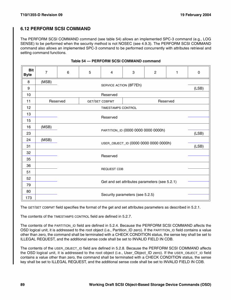
T10/1355-D Revision 09 19 February 2004
6.12 PERFORM SCSI COMMAND
The PERFORM SCSI COMMAND command (see table 54) allows an implemented SPC-3 command (e.g., LOGSENSE) to be performed when the security method is not NOSEC (see 4.9.3). The PERFORM SCSI COMMANDcommand also allows an implemented SPC-3 command to be performed concurrently with attributes retrieval andsetting command functions.
The GET/SET CDBFMT field specifies the format of the get and set attributes parameters as described in 5.2.1.
The contents of the TIMESTAMPS CONTROL field are defined in 5.2.7.
The contents of the PARTITION_ID field are defined in 5.2.4. Because the PERFORM SCSI COMMAND affects theOSD logical unit, it is addressed to the root object (i.e., Partition_ID zero). If the PARTITION_ID field contains a valueother than zero, the command shall be terminated with a CHECK CONDITION status, the sense key shall be set toILLEGAL REQUEST, and the additional sense code shall be set to INVALID FIELD IN CDB.
The contents of the USER_OBJECT_ID field are defined in 5.2.8. Because the PERFORM SCSI COMMAND affectsthe OSD logical unit, it is addressed to the root object (i.e., User_Object_ID zero). If the USER_OBJECT_ID fieldcontains a value other than zero, the command shall be terminated with a CHECK CONDITION status, the sensekey shall be set to ILLEGAL REQUEST, and the additional sense code shall be set to INVALID FIELD IN CDB.
Table 54 — PERFORM SCSI COMMAND command
BitByte
7 6 5 4 3 2 1 0
8 (MSB)SERVICE ACTION (8F7Eh)
9 (LSB)
10 Reserved
11 Reserved GET/SET CDBFMT Reserved
12 TIMESTAMPS CONTROL
13Reserved
15
16 (MSB)PARTITION_ID (0000 0000 0000 0000h)
23 (LSB)
24 (MSB)USER_OBJECT_ID (0000 0000 0000 0000h)
31 (LSB)
32Reserved
35
36REQUEST CDB
51
52 Get and set attributes parameters (see 5.2.1)
79
80Security parameters (see 5.2.5)
173
89 Working Draft SCSI Object-Based Storage Device Commands (OSD)
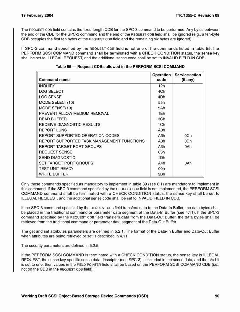
19 February 2004 T10/1355-D Revision 09
The REQUEST CDB field contains the fixed-length CDB for the SPC-3 command to be performed. Any bytes betweenthe end of the CDB for the SPC-3 command and the end of the REQUEST CDB field shall be ignored (e.g., a ten-byteCDB occupies the first ten bytes of the REQUEST CDB field and the remaining six bytes are ignored).
If SPC-3 command specified by the REQUEST CDB field is not one of the commands listed in table 55, thePERFORM SCSI COMMAND command shall be terminated with a CHECK CONDITION status, the sense keyshall be set to ILLEGAL REQUEST, and the additional sense code shall be set to INVALID FIELD IN CDB.
Only those commands specified as mandatory to implement in table 39 (see 6.1) are mandatory to implement inthis command. If the SPC-3 command specified by the REQUEST CDB field is not implemented, the PERFORM SCSICOMMAND command shall be terminated with a CHECK CONDITION status, the sense key shall be set toILLEGAL REQUEST, and the additional sense code shall be set to INVALID FIELD IN CDB.
If the SPC-3 command specified by the REQUEST CDB field transfers data to the Data-In Buffer, the data bytes shallbe placed in the traditional command or parameter data segment of the Data-In Buffer (see 4.11). If the SPC-3command specified by the REQUEST CDB field transfers data from the Data-Out Buffer, the data bytes shall beretrieved from the traditional command or parameter data segment of the Data-Out Buffer.
The get and set attributes parameters are defined in 5.2.1. The format of the Data-In Buffer and Data-Out Bufferwhen attributes are being retrieved or set is described in 4.11.
The security parameters are defined in 5.2.5.
If the PERFORM SCSI COMMAND is terminated with a CHECK CONDITION status, the sense key is ILLEGALREQUEST, the sense key specific sense data descriptor (see SPC-3) is included in the sense data, and the C/D bitis set to one, then values in the FIELD POINTER field shall be based on the PERFORM SCSI COMMAND CDB (i.e.,not on the CDB in the REQUEST CDB field).
Table 55 — Request CDBs allowed in the PERFORM SCSI COMMAND
Command nameOperation
codeService action
(if any)
INQUIRY 12hLOG SELECT 4ChLOG SENSE 4DhMODE SELECT(10) 55hMODE SENSE(10) 5AhPREVENT ALLOW MEDIUM REMOVAL 1EhREAD BUFFER 3ChRECEIVE DIAGNOSTIC RESULTS 1ChREPORT LUNS A0hREPORT SUPPORTED OPERATION CODES A3h 0ChREPORT SUPPORTED TASK MANAGEMENT FUNCTIONS A3h 0DhREPORT TARGET PORT GROUPS A3h 0AhREQUEST SENSE 03hSEND DIAGNOSTIC 1DhSET TARGET PORT GROUPS A4h 0AhTEST UNIT READY 00hWRITE BUFFER 3Bh
Working Draft SCSI Object-Based Storage Device Commands (OSD) 90
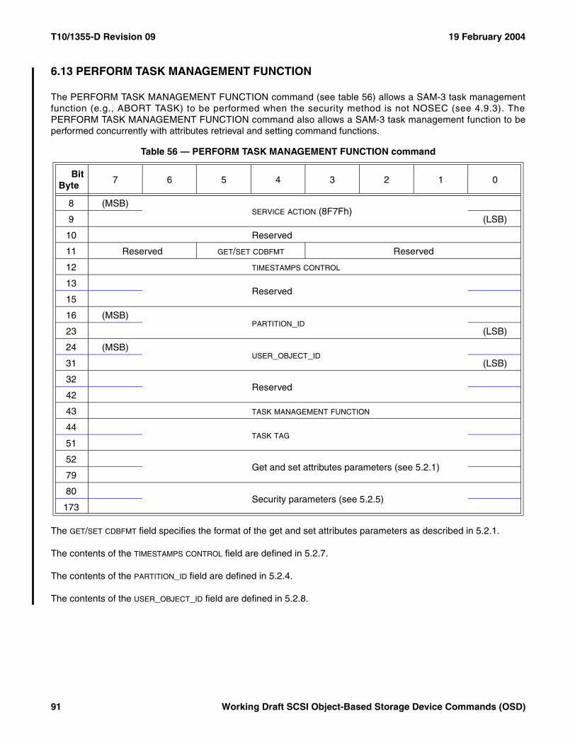
T10/1355-D Revision 09 19 February 2004
6.13 PERFORM TASK MANAGEMENT FUNCTION
The PERFORM TASK MANAGEMENT FUNCTION command (see table 56) allows a SAM-3 task managementfunction (e.g., ABORT TASK) to be performed when the security method is not NOSEC (see 4.9.3). ThePERFORM TASK MANAGEMENT FUNCTION command also allows a SAM-3 task management function to beperformed concurrently with attributes retrieval and setting command functions.
The GET/SET CDBFMT field specifies the format of the get and set attributes parameters as described in 5.2.1.
The contents of the TIMESTAMPS CONTROL field are defined in 5.2.7.
The contents of the PARTITION_ID field are defined in 5.2.4.
The contents of the USER_OBJECT_ID field are defined in 5.2.8.
Table 56 — PERFORM TASK MANAGEMENT FUNCTION command
BitByte
7 6 5 4 3 2 1 0
8 (MSB)SERVICE ACTION (8F7Fh)
9 (LSB)
10 Reserved
11 Reserved GET/SET CDBFMT Reserved
12 TIMESTAMPS CONTROL
13Reserved
15
16 (MSB)PARTITION_ID
23 (LSB)
24 (MSB)USER_OBJECT_ID
31 (LSB)
32Reserved
42
43 TASK MANAGEMENT FUNCTION
44TASK TAG
51
52 Get and set attributes parameters (see 5.2.1)
79
80Security parameters (see 5.2.5)
173
91 Working Draft SCSI Object-Based Storage Device Commands (OSD)
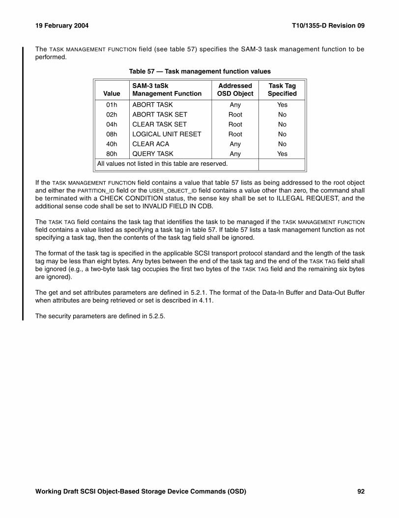
19 February 2004 T10/1355-D Revision 09
The TASK MANAGEMENT FUNCTION field (see table 57) specifies the SAM-3 task management function to beperformed.
If the TASK MANAGEMENT FUNCTION field contains a value that table 57 lists as being addressed to the root objectand either the PARTITION_ID field or the USER_OBJECT_ID field contains a value other than zero, the command shallbe terminated with a CHECK CONDITION status, the sense key shall be set to ILLEGAL REQUEST, and theadditional sense code shall be set to INVALID FIELD IN CDB.
The TASK TAG field contains the task tag that identifies the task to be managed if the TASK MANAGEMENT FUNCTION
field contains a value listed as specifying a task tag in table 57. If table 57 lists a task management function as notspecifying a task tag, then the contents of the task tag field shall be ignored.
The format of the task tag is specified in the applicable SCSI transport protocol standard and the length of the tasktag may be less than eight bytes. Any bytes between the end of the task tag and the end of the TASK TAG field shallbe ignored (e.g., a two-byte task tag occupies the first two bytes of the TASK TAG field and the remaining six bytesare ignored).
The get and set attributes parameters are defined in 5.2.1. The format of the Data-In Buffer and Data-Out Bufferwhen attributes are being retrieved or set is described in 4.11.
The security parameters are defined in 5.2.5.
Table 57 — Task management function values
ValueSAM-3 taSk Management Function
Addressed OSD Object
Task Tag Specified
01h ABORT TASK Any Yes
02h ABORT TASK SET Root No
04h CLEAR TASK SET Root No
08h LOGICAL UNIT RESET Root No
40h CLEAR ACA Any No
80h QUERY TASK Any Yes
All values not listed in this table are reserved.
Working Draft SCSI Object-Based Storage Device Commands (OSD) 92
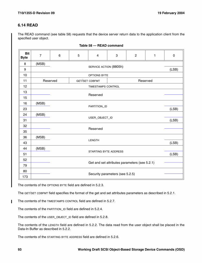
T10/1355-D Revision 09 19 February 2004
6.14 READ
The READ command (see table 58) requests that the device server return data to the application client from thespecified user object.
The contents of the OPTIONS BYTE field are defined in 5.2.3.
The GET/SET CDBFMT field specifies the format of the get and set attributes parameters as described in 5.2.1.
The contents of the TIMESTAMPS CONTROL field are defined in 5.2.7.
The contents of the PARTITION_ID field are defined in 5.2.4.
The contents of the USER_OBJECT_ID field are defined in 5.2.8.
The contents of the LENGTH field are defined in 5.2.2. The data read from the user object shall be placed in theData-In Buffer as described in 5.2.2.
The contents of the STARTING BYTE ADDRESS field are defined in 5.2.6.
Table 58 — READ command
BitByte
7 6 5 4 3 2 1 0
8 (MSB)SERVICE ACTION (8805h)
9 (LSB)
10 OPTIONS BYTE
11 Reserved GET/SET CDBFMT Reserved
12 TIMESTAMPS CONTROL
13Reserved
15
16 (MSB)PARTITION_ID
23 (LSB)
24 (MSB)USER_OBJECT_ID
31 (LSB)
32Reserved
35
36 (MSB)LENGTH
43 (LSB)
44 (MSB)STARTING BYTE ADDRESS
51 (LSB)
52 Get and set attributes parameters (see 5.2.1)
79
80Security parameters (see 5.2.5)
173
93 Working Draft SCSI Object-Based Storage Device Commands (OSD)
19 February 2004 T10/1355-D Revision 09
If the STARTING BYTE ADDRESS field specifies a byte that is beyond the user object logical length attribute value inthe User Object Information attributes page (see 7.1.2.11), then:
a) No bytes shall be transferred;b) The command shall be terminated with a CHECK CONDITION status;c) The sense key shall be set to ILLEGAL REQUEST; andd) The additional sense code shall be set to INVALID FIELD IN CDB.
If the values in the LENGTH field and STARTING BYTE ADDRESS field result an attempt to read a byte that is beyond theuser object logical length attribute value in the User Object Information attributes page, then:
a) The bytes between the starting byte address and the user object logical length shall be transferred;b) The command shall be terminated with a CHECK CONDITION status;c) The sense key shall be set to RECOVERED ERROR;d) The additional sense code shall be set to READ PAST END OF USER OBJECT;e) The command-specific information sense data descriptor (see SPC-3) shall be included in the sense data;
andf) The COMMAND-SPECIFIC INFORMATION field shall contain the number of bytes transferred.
Attempts to read bytes that have never been written shall result in zeros being returned.
The get and set attributes parameters are defined in 5.2.1. The format of the Data-In Buffer and Data-Out Bufferwhen attributes are being retrieved or set is described in 4.11.
The security parameters are defined in 5.2.5.
Working Draft SCSI Object-Based Storage Device Commands (OSD) 94
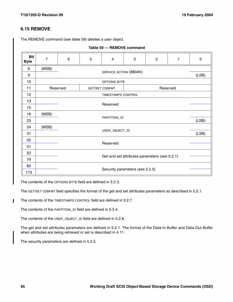
T10/1355-D Revision 09 19 February 2004
6.15 REMOVE
The REMOVE command (see table 59) deletes a user object.
The contents of the OPTIONS BYTE field are defined in 5.2.3.
The GET/SET CDBFMT field specifies the format of the get and set attributes parameters as described in 5.2.1.
The contents of the TIMESTAMPS CONTROL field are defined in 5.2.7.
The contents of the PARTITION_ID field are defined in 5.2.4.
The contents of the USER_OBJECT_ID field are defined in 5.2.8.
The get and set attributes parameters are defined in 5.2.1. The format of the Data-In Buffer and Data-Out Bufferwhen attributes are being retrieved or set is described in 4.11.
The security parameters are defined in 5.2.5.
Table 59 — REMOVE command
BitByte
7 6 5 4 3 2 1 0
8 (MSB)SERVICE ACTION (880Ah)
9 (LSB)
10 OPTIONS BYTE
11 Reserved GET/SET CDBFMT Reserved
12 TIMESTAMPS CONTROL
13Reserved
15
16 (MSB)PARTITION_ID
23 (LSB)
24 (MSB)USER_OBJECT_ID
31 (LSB)
32Reserved
51
52 Get and set attributes parameters (see 5.2.1)
79
80Security parameters (see 5.2.5)
173
95 Working Draft SCSI Object-Based Storage Device Commands (OSD)
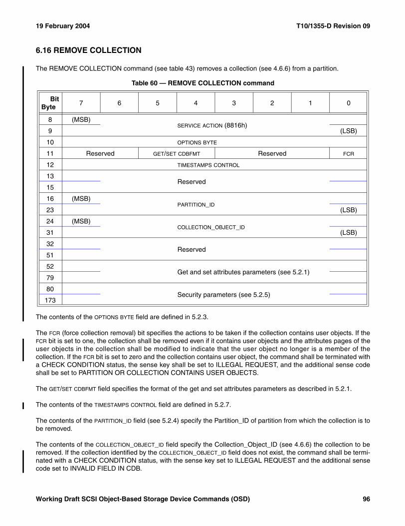
19 February 2004 T10/1355-D Revision 09
6.16 REMOVE COLLECTION
The REMOVE COLLECTION command (see table 43) removes a collection (see 4.6.6) from a partition.
The contents of the OPTIONS BYTE field are defined in 5.2.3.
The FCR (force collection removal) bit specifies the actions to be taken if the collection contains user objects. If theFCR bit is set to one, the collection shall be removed even if it contains user objects and the attributes pages of theuser objects in the collection shall be modified to indicate that the user object no longer is a member of thecollection. If the FCR bit is set to zero and the collection contains user object, the command shall be terminated witha CHECK CONDITION status, the sense key shall be set to ILLEGAL REQUEST, and the additional sense codeshall be set to PARTITION OR COLLECTION CONTAINS USER OBJECTS.
The GET/SET CDBFMT field specifies the format of the get and set attributes parameters as described in 5.2.1.
The contents of the TIMESTAMPS CONTROL field are defined in 5.2.7.
The contents of the PARTITION_ID field (see 5.2.4) specify the Partition_ID of partition from which the collection is tobe removed.
The contents of the COLLECTION_OBJECT_ID field specify the Collection_Object_ID (see 4.6.6) the collection to beremoved. If the collection identified by the COLLECTION_OBJECT_ID field does not exist, the command shall be termi-nated with a CHECK CONDITION status, with the sense key set to ILLEGAL REQUEST and the additional sensecode set to INVALID FIELD IN CDB.
Table 60 — REMOVE COLLECTION command
BitByte
7 6 5 4 3 2 1 0
8 (MSB)SERVICE ACTION (8816h)
9 (LSB)
10 OPTIONS BYTE
11 Reserved GET/SET CDBFMT Reserved FCR
12 TIMESTAMPS CONTROL
13Reserved
15
16 (MSB)PARTITION_ID
23 (LSB)
24 (MSB)COLLECTION_OBJECT_ID
31 (LSB)
32Reserved
51
52 Get and set attributes parameters (see 5.2.1)
79
80Security parameters (see 5.2.5)
173
Working Draft SCSI Object-Based Storage Device Commands (OSD) 96
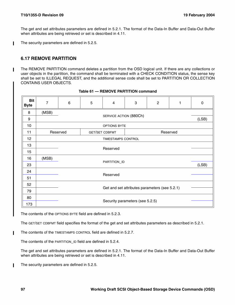
T10/1355-D Revision 09 19 February 2004
The get and set attributes parameters are defined in 5.2.1. The format of the Data-In Buffer and Data-Out Bufferwhen attributes are being retrieved or set is described in 4.11.
The security parameters are defined in 5.2.5.
6.17 REMOVE PARTITION
The REMOVE PARTITION command deletes a partition from the OSD logical unit. If there are any collections oruser objects in the partition, the command shall be terminated with a CHECK CONDITION status, the sense keyshall be set to ILLEGAL REQUEST, and the additional sense code shall be set to PARTITION OR COLLECTIONCONTAINS USER OBJECTS.
The contents of the OPTIONS BYTE field are defined in 5.2.3.
The GET/SET CDBFMT field specifies the format of the get and set attributes parameters as described in 5.2.1.
The contents of the TIMESTAMPS CONTROL field are defined in 5.2.7.
The contents of the PARTITION_ID field are defined in 5.2.4.
The get and set attributes parameters are defined in 5.2.1. The format of the Data-In Buffer and Data-Out Bufferwhen attributes are being retrieved or set is described in 4.11.
The security parameters are defined in 5.2.5.
Table 61 — REMOVE PARTITION command
BitByte
7 6 5 4 3 2 1 0
8 (MSB)SERVICE ACTION (880Ch)
9 (LSB)
10 OPTIONS BYTE
11 Reserved GET/SET CDBFMT Reserved
12 TIMESTAMPS CONTROL
13Reserved
15
16 (MSB)PARTITION_ID
23 (LSB)
24Reserved
51
52 Get and set attributes parameters (see 5.2.1)
79
80Security parameters (see 5.2.5)
173
97 Working Draft SCSI Object-Based Storage Device Commands (OSD)
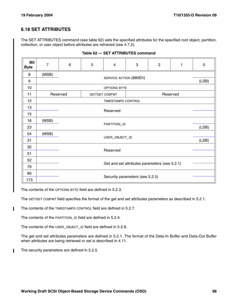
19 February 2004 T10/1355-D Revision 09
6.18 SET ATTRIBUTES
The SET ATTRIBUTES command (see table 62) sets the specified attributes for the specified root object, partition,collection, or user object before attributes are retrieved (see 4.7.2).
The contents of the OPTIONS BYTE field are defined in 5.2.3.
The GET/SET CDBFMT field specifies the format of the get and set attributes parameters as described in 5.2.1.
The contents of the TIMESTAMPS CONTROL field are defined in 5.2.7.
The contents of the PARTITION_ID field are defined in 5.2.4.
The contents of the USER_OBJECT_ID field are defined in 5.2.8.
The get and set attributes parameters are defined in 5.2.1. The format of the Data-In Buffer and Data-Out Bufferwhen attributes are being retrieved or set is described in 4.11.
The security parameters are defined in 5.2.5.
Table 62 — SET ATTRIBUTES command
BitByte
7 6 5 4 3 2 1 0
8 (MSB)SERVICE ACTION (880Eh)
9 (LSB)
10 OPTIONS BYTE
11 Reserved GET/SET CDBFMT Reserved
12 TIMESTAMPS CONTROL
13Reserved
15
16 (MSB)PARTITION_ID
23 (LSB)
24 (MSB)USER_OBJECT_ID
31 (LSB)
32Reserved
51
52 Get and set attributes parameters (see 5.2.1)
79
80Security parameters (see 5.2.5)
173
Working Draft SCSI Object-Based Storage Device Commands (OSD) 98
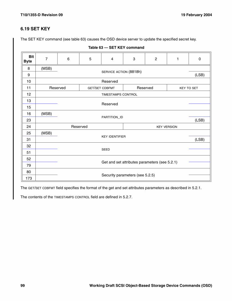
T10/1355-D Revision 09 19 February 2004
6.19 SET KEY
The SET KEY command (see table 63) causes the OSD device server to update the specified secret key.
The GET/SET CDBFMT field specifies the format of the get and set attributes parameters as described in 5.2.1.
The contents of the TIMESTAMPS CONTROL field are defined in 5.2.7.
Table 63 — SET KEY command
BitByte
7 6 5 4 3 2 1 0
8 (MSB)SERVICE ACTION (8818h)
9 (LSB)
10 Reserved
11 Reserved GET/SET CDBFMT Reserved KEY TO SET
12 TIMESTAMPS CONTROL
13Reserved
15
16 (MSB)PARTITION_ID
23 (LSB)
24 Reserved KEY VERSION
25 (MSB)KEY IDENTIFIER
31 (LSB)
32SEED
51
52 Get and set attributes parameters (see 5.2.1)
79
80Security parameters (see 5.2.5)
173
99 Working Draft SCSI Object-Based Storage Device Commands (OSD)
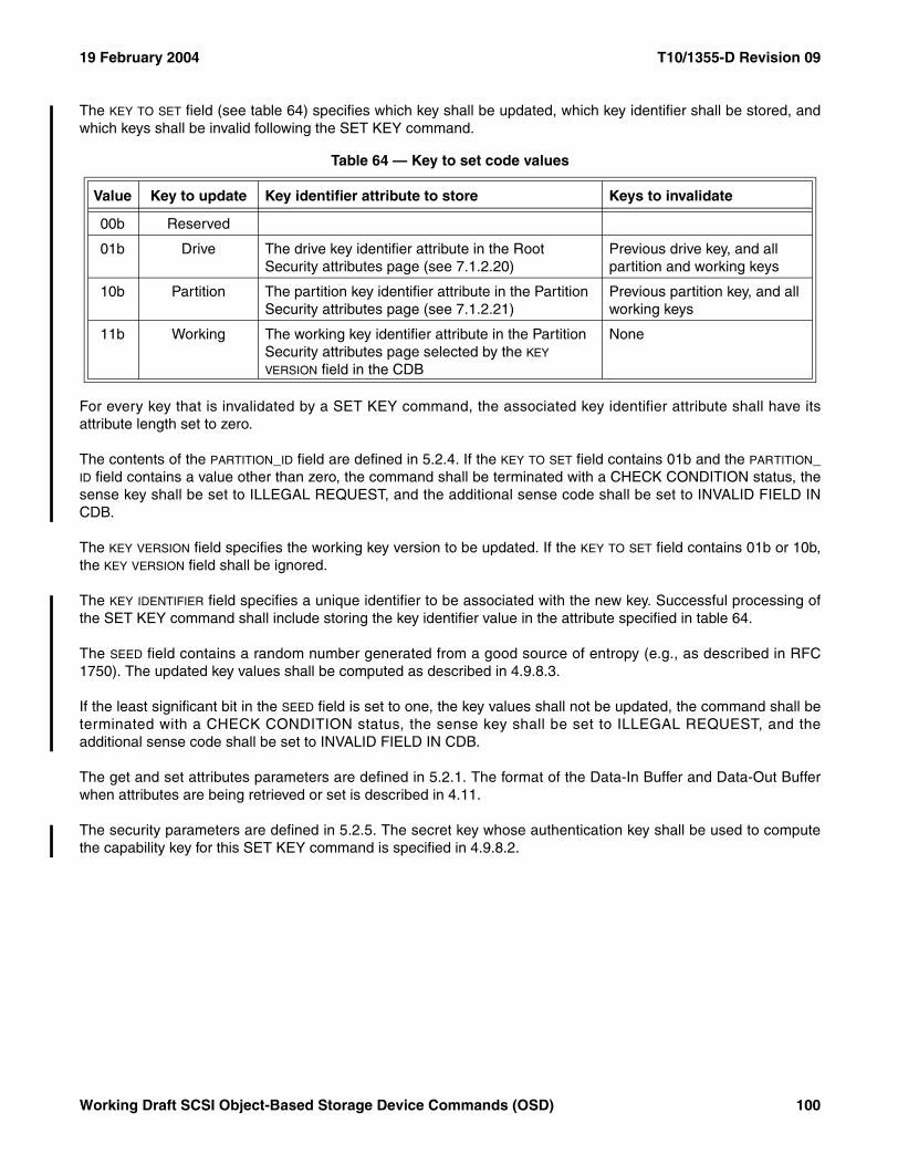
19 February 2004 T10/1355-D Revision 09
The KEY TO SET field (see table 64) specifies which key shall be updated, which key identifier shall be stored, andwhich keys shall be invalid following the SET KEY command.
For every key that is invalidated by a SET KEY command, the associated key identifier attribute shall have itsattribute length set to zero.
The contents of the PARTITION_ID field are defined in 5.2.4. If the KEY TO SET field contains 01b and the PARTITION_ID field contains a value other than zero, the command shall be terminated with a CHECK CONDITION status, thesense key shall be set to ILLEGAL REQUEST, and the additional sense code shall be set to INVALID FIELD INCDB.
The KEY VERSION field specifies the working key version to be updated. If the KEY TO SET field contains 01b or 10b,the KEY VERSION field shall be ignored.
The KEY IDENTIFIER field specifies a unique identifier to be associated with the new key. Successful processing ofthe SET KEY command shall include storing the key identifier value in the attribute specified in table 64.
The SEED field contains a random number generated from a good source of entropy (e.g., as described in RFC1750). The updated key values shall be computed as described in 4.9.8.3.
If the least significant bit in the SEED field is set to one, the key values shall not be updated, the command shall beterminated with a CHECK CONDITION status, the sense key shall be set to ILLEGAL REQUEST, and theadditional sense code shall be set to INVALID FIELD IN CDB.
The get and set attributes parameters are defined in 5.2.1. The format of the Data-In Buffer and Data-Out Bufferwhen attributes are being retrieved or set is described in 4.11.
The security parameters are defined in 5.2.5. The secret key whose authentication key shall be used to computethe capability key for this SET KEY command is specified in 4.9.8.2.
Table 64 — Key to set code values
Value Key to update Key identifier attribute to store Keys to invalidate
00b Reserved
01b Drive The drive key identifier attribute in the Root Security attributes page (see 7.1.2.20)
Previous drive key, and all partition and working keys
10b Partition The partition key identifier attribute in the Partition Security attributes page (see 7.1.2.21)
Previous partition key, and all working keys
11b Working The working key identifier attribute in the Partition Security attributes page selected by the KEY VERSION field in the CDB
None
Working Draft SCSI Object-Based Storage Device Commands (OSD) 100
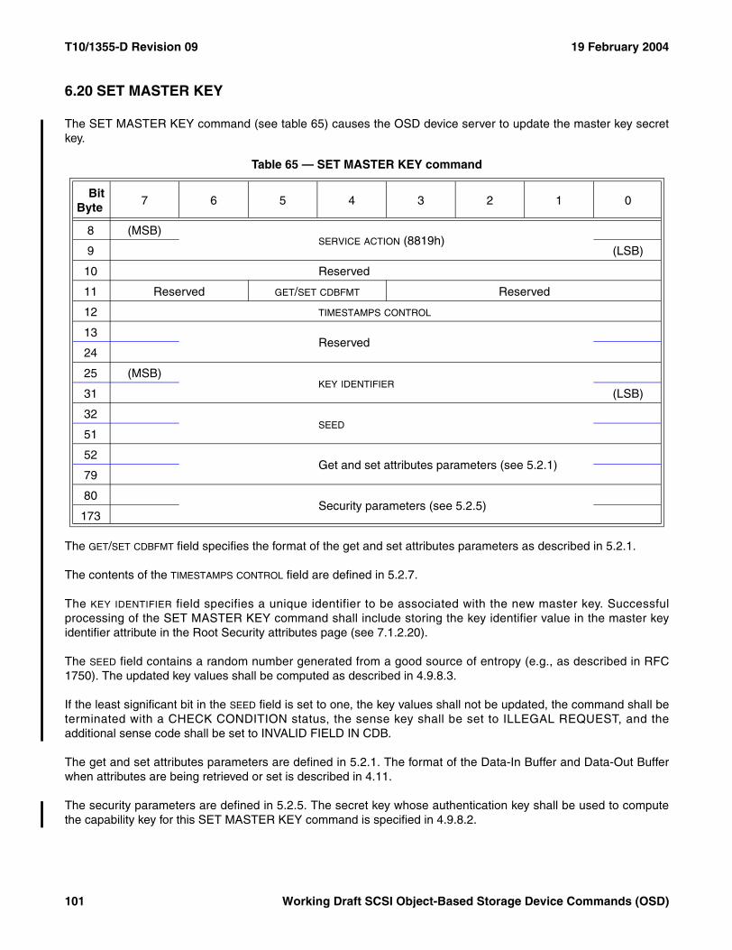
T10/1355-D Revision 09 19 February 2004
6.20 SET MASTER KEY
The SET MASTER KEY command (see table 65) causes the OSD device server to update the master key secretkey.
The GET/SET CDBFMT field specifies the format of the get and set attributes parameters as described in 5.2.1.
The contents of the TIMESTAMPS CONTROL field are defined in 5.2.7.
The KEY IDENTIFIER field specifies a unique identifier to be associated with the new master key. Successfulprocessing of the SET MASTER KEY command shall include storing the key identifier value in the master keyidentifier attribute in the Root Security attributes page (see 7.1.2.20).
The SEED field contains a random number generated from a good source of entropy (e.g., as described in RFC1750). The updated key values shall be computed as described in 4.9.8.3.
If the least significant bit in the SEED field is set to one, the key values shall not be updated, the command shall beterminated with a CHECK CONDITION status, the sense key shall be set to ILLEGAL REQUEST, and theadditional sense code shall be set to INVALID FIELD IN CDB.
The get and set attributes parameters are defined in 5.2.1. The format of the Data-In Buffer and Data-Out Bufferwhen attributes are being retrieved or set is described in 4.11.
The security parameters are defined in 5.2.5. The secret key whose authentication key shall be used to computethe capability key for this SET MASTER KEY command is specified in 4.9.8.2.
Table 65 — SET MASTER KEY command
BitByte
7 6 5 4 3 2 1 0
8 (MSB)SERVICE ACTION (8819h)
9 (LSB)
10 Reserved
11 Reserved GET/SET CDBFMT Reserved
12 TIMESTAMPS CONTROL
13Reserved
24
25 (MSB)KEY IDENTIFIER
31 (LSB)
32SEED
51
52 Get and set attributes parameters (see 5.2.1)
79
80Security parameters (see 5.2.5)
173
101 Working Draft SCSI Object-Based Storage Device Commands (OSD)
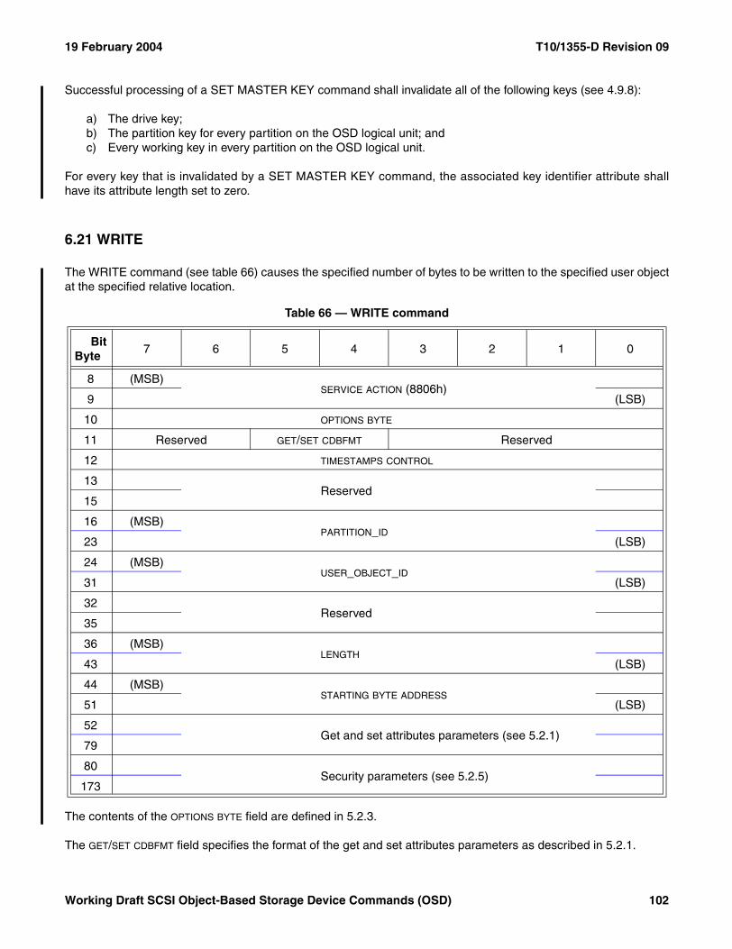
19 February 2004 T10/1355-D Revision 09
Successful processing of a SET MASTER KEY command shall invalidate all of the following keys (see 4.9.8):
a) The drive key;b) The partition key for every partition on the OSD logical unit; andc) Every working key in every partition on the OSD logical unit.
For every key that is invalidated by a SET MASTER KEY command, the associated key identifier attribute shallhave its attribute length set to zero.
6.21 WRITE
The WRITE command (see table 66) causes the specified number of bytes to be written to the specified user objectat the specified relative location.
The contents of the OPTIONS BYTE field are defined in 5.2.3.
The GET/SET CDBFMT field specifies the format of the get and set attributes parameters as described in 5.2.1.
Table 66 — WRITE command
BitByte
7 6 5 4 3 2 1 0
8 (MSB)SERVICE ACTION (8806h)
9 (LSB)
10 OPTIONS BYTE
11 Reserved GET/SET CDBFMT Reserved
12 TIMESTAMPS CONTROL
13Reserved
15
16 (MSB)PARTITION_ID
23 (LSB)
24 (MSB)USER_OBJECT_ID
31 (LSB)
32Reserved
35
36 (MSB)LENGTH
43 (LSB)
44 (MSB)STARTING BYTE ADDRESS
51 (LSB)
52 Get and set attributes parameters (see 5.2.1)
79
80Security parameters (see 5.2.5)
173
Working Draft SCSI Object-Based Storage Device Commands (OSD) 102
T10/1355-D Revision 09 19 February 2004
The contents of the TIMESTAMPS CONTROL field are defined in 5.2.7.
The contents of the PARTITION_ID field are defined in 5.2.4.
The contents of the USER_OBJECT_ID field are defined in 5.2.8.
The contents of the LENGTH field are defined in 5.2.2. The data to be written to the user object shall be placed in theData-Out Buffer as described in 5.2.2.
The contents of the STARTING BYTE ADDRESS field are defined in 5.2.6.
A WRITE to a byte that is greater than the value in the user object logical length attribute in the User Object Infor-mation attributes page (see 7.1.2.11) shall implicitly increase the value in the user object logical length attribute tothe largest byte written.
The get and set attributes parameters are defined in 5.2.1. The format of the Data-In Buffer and Data-Out Bufferwhen attributes are being retrieved or set is described in 4.11.
The security parameters are defined in 5.2.5.
If a CREATE AND WRITE command causes the value in the user object logical length attribute in the User ObjectInformation attributes page (see 7.1.2.11) to exceed the value in the maximum user object length attribute in theThe COLLECTIONS PER USER OBJECT field contains the value of the collections per user object attribute., then a quotaerror shall be generated (see 4.8.2). The quota testing principles described in 4.8.3 apply to the testing of themaximum user object length quota.
If a CREATE AND WRITE command causes the value in the used capacity attribute in the Partition Informationattributes page (see 7.1.2.9) to exceed the value in the capacity quota attribute in the Partition Quotas attributespage (see 7.1.2.13), then a quota error shall be generated (see 4.8.2). The quota testing principles described in4.8.3 apply to the testing of the capacity quota.
103 Working Draft SCSI Object-Based Storage Device Commands (OSD)
19 February 2004 T10/1355-D Revision 09
7 Parameters for OSD type devices
7.1 Attributes parameters
7.1.1 Attributes parameter formats
The following formats shall be provided for attributes parameter data:
a) Page format (see 7.1.2); andb) List format (see 7.1.3).
Page format parameter data allows retrieval of them in formatted pages where only the attribute values appear inthe parameter data.
Those attributes pages that do not have a defined page format are not accessible via page format parameter data(e.g., the Root Directory attributes page defined in 7.1.2.4).
List format parameter data handles individual attributes in an identifier, length, value format, allowing access to anygroup of attributes in any order.
Attribute access is limited to the:
a) Attributes associated with the OSD object addressed by the command; andb) Attributes in the Current Command attributes page (see 7.1.2.24).
The format of the Data-In Buffer and Data-Out Buffer when attributes meta data is being used is described in 4.11.
A get attributes request for an attribute or attributes page having no previously established value shall not beconsidered an error. If an attribute value that has not been previously established is requested, a list entry formatvalue (see 7.1.3.3) having zero in the ATTRIBUTE LENGTH field shall be returned. If an attributes page that has noestablished definition is requested, a null attributes page (see 7.1.2.25) shall be returned.
7.1.2 OSD attributes pages
7.1.2.1 Attributes pages overview
Every attributes page is identified by a page number (see 4.7.3). Every attributes page includes attribute number0h whose contents are defined in 7.1.2.2.
In addition to attribute number 0h, an attributes page is composed of attribute values numbered 1h through FFFFFFFEh.
Working Draft SCSI Object-Based Storage Device Commands (OSD) 104
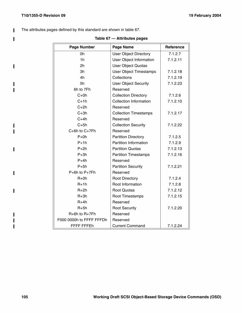
T10/1355-D Revision 09 19 February 2004
The attributes pages defined by this standard are shown in table 67.
Table 67 — Attributes pages
Page Number Page Name Reference
0h User Object Directory 7.1.2.7
1h User Object Information 7.1.2.11
2h User Object Quotas
3h User Object Timestamps 7.1.2.18
4h Collections 7.1.2.19
5h User Object Security 7.1.2.23
6h to 7Fh Reserved
C+0h Collection Directory 7.1.2.6
C+1h Collection Information 7.1.2.10
C+2h Reserved
C+3h Collection Timestamps 7.1.2.17
C+4h Reserved
C+5h Collection Security 7.1.2.22
C+6h to C+7Fh Reserved
P+0h Partition Directory 7.1.2.5
P+1h Partition Information 7.1.2.9
P+2h Partition Quotas 7.1.2.13
P+3h Partition Timestamps 7.1.2.16
P+4h Reserved
P+5h Partition Security 7.1.2.21
P+6h to P+7Fh Reserved
R+0h Root Directory 7.1.2.4
R+1h Root Information 7.1.2.8
R+2h Root Quotas 7.1.2.12
R+3h Root Timestamps 7.1.2.15
R+4h Reserved
R+5h Root Security 7.1.2.20
R+6h to R+7Fh Reserved
F000 0000h to FFFF FFFDh Reserved
FFFF FFFEh Current Command 7.1.2.24
105 Working Draft SCSI Object-Based Storage Device Commands (OSD)
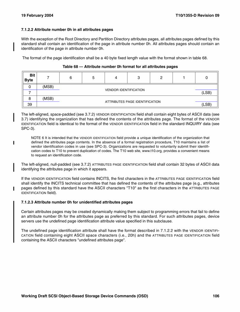
19 February 2004 T10/1355-D Revision 09
7.1.2.2 Attribute number 0h in all attributes pages
With the exception of the Root Directory and Partition Directory attributes pages, all attributes pages defined by thisstandard shall contain an identification of the page in attribute number 0h. All attributes pages should contain anidentification of the page in attribute number 0h.
The format of the page identification shall be a 40 byte fixed length value with the format shown in table 68.
The left-aligned, space-padded (see 3.7.2) VENDOR IDENTIFICATION field shall contain eight bytes of ASCII data (see3.7) identifying the organization that has defined the contents of the attributes page. The format of the VENDOR
IDENTIFICATION field is identical to the format of the VENDOR IDENTIFICATION field in the standard INQUIRY data (seeSPC-3).
NOTE 6 It is intended that the VENDOR IDENTIFICATION field provide a unique identification of the organization thatdefined the attributes page contents. In the absence of a formal registration procedure, T10 maintains a list ofvendor identification codes in use (see SPC-3). Organizations are requested to voluntarily submit their identifi-cation codes to T10 to prevent duplication of codes. The T10 web site, www.t10.org, provides a convenient meansto request an identification code.
The left-aligned, null-padded (see 3.7.2) ATTRIBUTES PAGE IDENTIFICATION field shall contain 32 bytes of ASCII dataidentifying the attributes page in which it appears.
If the VENDOR IDENTIFICATION field contains INCITS, the first characters in the ATTRIBUTES PAGE IDENTIFICATION fieldshall identify the INCITS technical committee that has defined the contents of the attributes page (e.g., attributespages defined by this standard have the ASCII characters "T10" as the first characters in the ATTRIBUTES PAGE
IDENTIFICATION field).
7.1.2.3 Attribute number 0h for unidentified attributes pages
Certain attributes pages may be created dynamically making them subject to programming errors that fail to definean attribute number 0h for the attributes page as preferred by this standard. For such attributes pages, deviceservers use the undefined page identification attribute value specified in this subclause.
The undefined page identification attribute shall have the format described in 7.1.2.2 with the VENDOR IDENTIFI-CATION field containing eight ASCII space characters (i.e., 20h) and the ATTRIBUTES PAGE IDENTIFICATION fieldcontaining the ASCII characters "undefined attributes page".
Table 68 — Attribute number 0h format for all attributes pages
BitByte
7 6 5 4 3 2 1 0
0 (MSB)VENDOR IDENTIFICATION
7 (LSB)
8 (MSB)ATTRIBUTES PAGE IDENTIFICATION
39 (LSB)
Working Draft SCSI Object-Based Storage Device Commands (OSD) 106
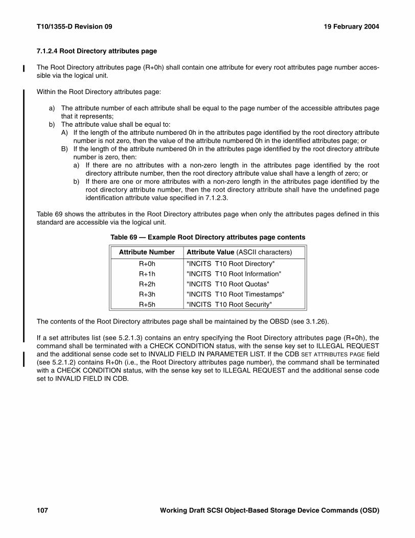
T10/1355-D Revision 09 19 February 2004
7.1.2.4 Root Directory attributes page
The Root Directory attributes page (R+0h) shall contain one attribute for every root attributes page number acces-sible via the logical unit.
Within the Root Directory attributes page:
a) The attribute number of each attribute shall be equal to the page number of the accessible attributes pagethat it represents;
b) The attribute value shall be equal to:A) If the length of the attribute numbered 0h in the attributes page identified by the root directory attribute
number is not zero, then the value of the attribute numbered 0h in the identified attributes page; orB) If the length of the attribute numbered 0h in the attributes page identified by the root directory attribute
number is zero, then:a) If there are no attributes with a non-zero length in the attributes page identified by the root
directory attribute number, then the root directory attribute value shall have a length of zero; orb) If there are one or more attributes with a non-zero length in the attributes page identified by the
root directory attribute number, then the root directory attribute shall have the undefined pageidentification attribute value specified in 7.1.2.3.
Table 69 shows the attributes in the Root Directory attributes page when only the attributes pages defined in thisstandard are accessible via the logical unit.
The contents of the Root Directory attributes page shall be maintained by the OBSD (see 3.1.26).
If a set attributes list (see 5.2.1.3) contains an entry specifying the Root Directory attributes page (R+0h), thecommand shall be terminated with a CHECK CONDITION status, with the sense key set to ILLEGAL REQUESTand the additional sense code set to INVALID FIELD IN PARAMETER LIST. If the CDB SET ATTRIBUTES PAGE field(see 5.2.1.2) contains R+0h (i.e., the Root Directory attributes page number), the command shall be terminatedwith a CHECK CONDITION status, with the sense key set to ILLEGAL REQUEST and the additional sense codeset to INVALID FIELD IN CDB.
Table 69 — Example Root Directory attributes page contents
Attribute Number Attribute Value (ASCII characters)
R+0h "INCITS T10 Root Directory"
R+1h "INCITS T10 Root Information"
R+2h "INCITS T10 Root Quotas"
R+3h "INCITS T10 Root Timestamps"
R+5h "INCITS T10 Root Security"
107 Working Draft SCSI Object-Based Storage Device Commands (OSD)
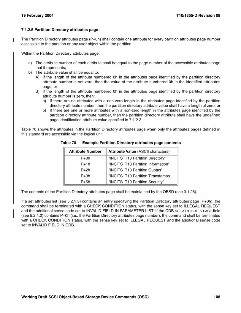
19 February 2004 T10/1355-D Revision 09
7.1.2.5 Partition Directory attributes page
The Partition Directory attributes page (P+0h) shall contain one attribute for every partition attributes page numberaccessible to the partition or any user object within the partition.
Within the Partition Directory attributes page:
a) The attribute number of each attribute shall be equal to the page number of the accessible attributes pagethat it represents;
b) The attribute value shall be equal to:A) If the length of the attribute numbered 0h in the attributes page identified by the partition directory
attribute number is not zero, then the value of the attribute numbered 0h in the identified attributespage; or
B) If the length of the attribute numbered 0h in the attributes page identified by the partition directoryattribute number is zero, then:a) If there are no attributes with a non-zero length in the attributes page identified by the partition
directory attribute number, then the partition directory attribute value shall have a length of zero; orb) If there are one or more attributes with a non-zero length in the attributes page identified by the
partition directory attribute number, then the partition directory attribute shall have the undefinedpage identification attribute value specified in 7.1.2.3.
Table 70 shows the attributes in the Partition Directory attributes page when only the attributes pages defined inthis standard are accessible via the logical unit.
The contents of the Partition Directory attributes page shall be maintained by the OBSD (see 3.1.26).
If a set attributes list (see 5.2.1.3) contains an entry specifying the Partition Directory attributes page (P+0h), thecommand shall be terminated with a CHECK CONDITION status, with the sense key set to ILLEGAL REQUESTand the additional sense code set to INVALID FIELD IN PARAMETER LIST. If the CDB SET ATTRIBUTES PAGE field(see 5.2.1.2) contains P+0h (i.e., the Partition Directory attributes page number), the command shall be terminatedwith a CHECK CONDITION status, with the sense key set to ILLEGAL REQUEST and the additional sense codeset to INVALID FIELD IN CDB.
Table 70 — Example Partition Directory attributes page contents
Attribute Number Attribute Value (ASCII characters)
P+0h "INCITS T10 Partition Directory"
P+1h "INCITS T10 Partition Information"
P+2h "INCITS T10 Partition Quotas"
P+3h "INCITS T10 Partition Timestamps"
P+5h "INCITS T10 Partition Security"
Working Draft SCSI Object-Based Storage Device Commands (OSD) 108
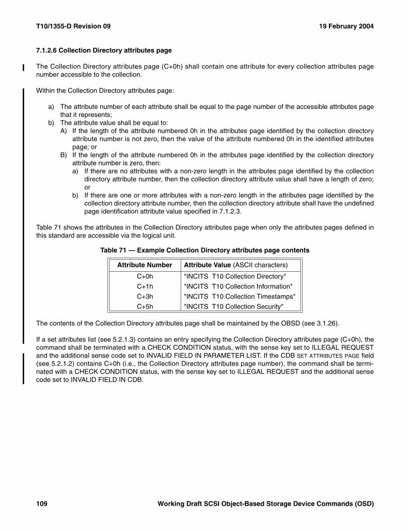
T10/1355-D Revision 09 19 February 2004
7.1.2.6 Collection Directory attributes page
The Collection Directory attributes page (C+0h) shall contain one attribute for every collection attributes pagenumber accessible to the collection.
Within the Collection Directory attributes page:
a) The attribute number of each attribute shall be equal to the page number of the accessible attributes pagethat it represents;
b) The attribute value shall be equal to:A) If the length of the attribute numbered 0h in the attributes page identified by the collection directory
attribute number is not zero, then the value of the attribute numbered 0h in the identified attributespage; or
B) If the length of the attribute numbered 0h in the attributes page identified by the collection directoryattribute number is zero, then:a) If there are no attributes with a non-zero length in the attributes page identified by the collection
directory attribute number, then the collection directory attribute value shall have a length of zero;or
b) If there are one or more attributes with a non-zero length in the attributes page identified by thecollection directory attribute number, then the collection directory attribute shall have the undefinedpage identification attribute value specified in 7.1.2.3.
Table 71 shows the attributes in the Collection Directory attributes page when only the attributes pages defined inthis standard are accessible via the logical unit.
The contents of the Collection Directory attributes page shall be maintained by the OBSD (see 3.1.26).
If a set attributes list (see 5.2.1.3) contains an entry specifying the Collection Directory attributes page (C+0h), thecommand shall be terminated with a CHECK CONDITION status, with the sense key set to ILLEGAL REQUESTand the additional sense code set to INVALID FIELD IN PARAMETER LIST. If the CDB SET ATTRIBUTES PAGE field(see 5.2.1.2) contains C+0h (i.e., the Collection Directory attributes page number), the command shall be termi-nated with a CHECK CONDITION status, with the sense key set to ILLEGAL REQUEST and the additional sensecode set to INVALID FIELD IN CDB.
Table 71 — Example Collection Directory attributes page contents
Attribute Number Attribute Value (ASCII characters)
C+0h "INCITS T10 Collection Directory"
C+1h "INCITS T10 Collection Information"
C+3h "INCITS T10 Collection Timestamps"
C+5h "INCITS T10 Collection Security"
109 Working Draft SCSI Object-Based Storage Device Commands (OSD)
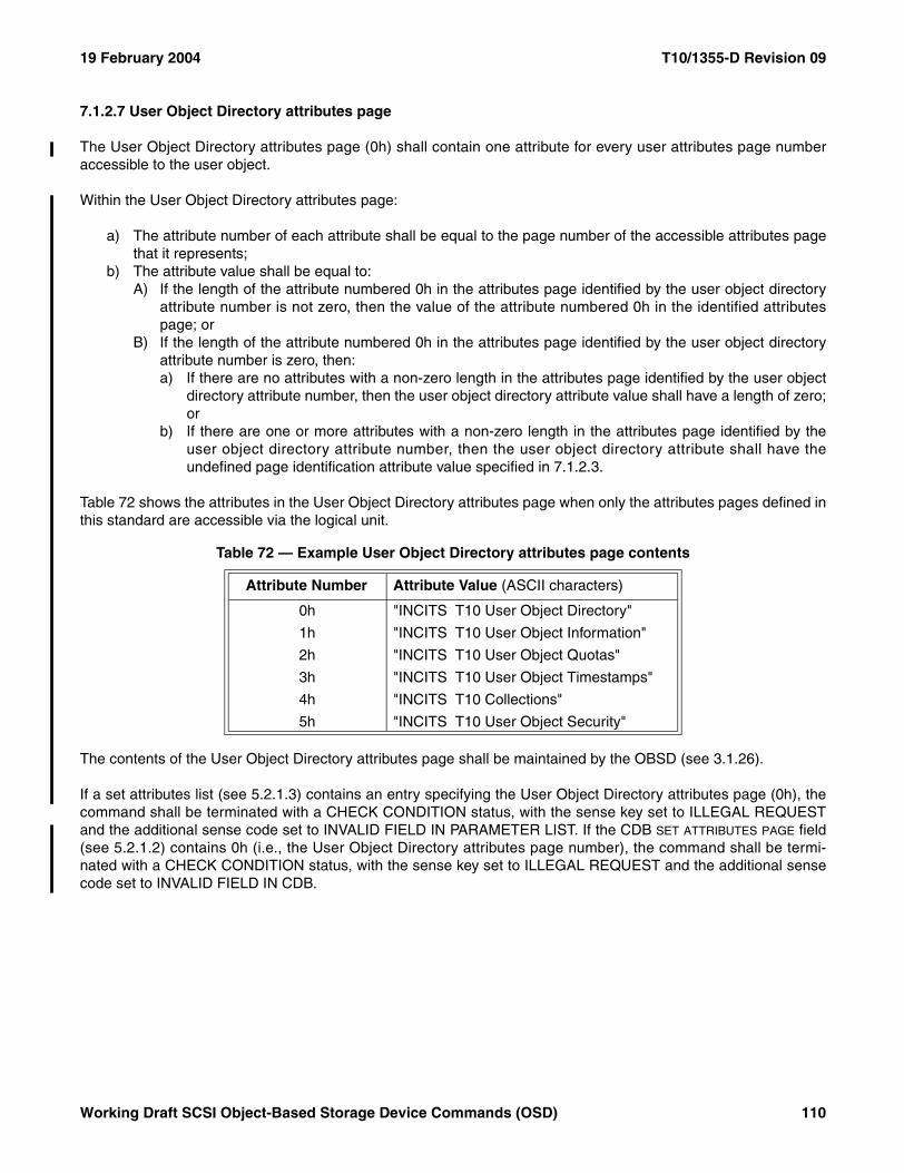
19 February 2004 T10/1355-D Revision 09
7.1.2.7 User Object Directory attributes page
The User Object Directory attributes page (0h) shall contain one attribute for every user attributes page numberaccessible to the user object.
Within the User Object Directory attributes page:
a) The attribute number of each attribute shall be equal to the page number of the accessible attributes pagethat it represents;
b) The attribute value shall be equal to:A) If the length of the attribute numbered 0h in the attributes page identified by the user object directory
attribute number is not zero, then the value of the attribute numbered 0h in the identified attributespage; or
B) If the length of the attribute numbered 0h in the attributes page identified by the user object directoryattribute number is zero, then:a) If there are no attributes with a non-zero length in the attributes page identified by the user object
directory attribute number, then the user object directory attribute value shall have a length of zero;or
b) If there are one or more attributes with a non-zero length in the attributes page identified by theuser object directory attribute number, then the user object directory attribute shall have theundefined page identification attribute value specified in 7.1.2.3.
Table 72 shows the attributes in the User Object Directory attributes page when only the attributes pages defined inthis standard are accessible via the logical unit.
The contents of the User Object Directory attributes page shall be maintained by the OBSD (see 3.1.26).
If a set attributes list (see 5.2.1.3) contains an entry specifying the User Object Directory attributes page (0h), thecommand shall be terminated with a CHECK CONDITION status, with the sense key set to ILLEGAL REQUESTand the additional sense code set to INVALID FIELD IN PARAMETER LIST. If the CDB SET ATTRIBUTES PAGE field(see 5.2.1.2) contains 0h (i.e., the User Object Directory attributes page number), the command shall be termi-nated with a CHECK CONDITION status, with the sense key set to ILLEGAL REQUEST and the additional sensecode set to INVALID FIELD IN CDB.
Table 72 — Example User Object Directory attributes page contents
Attribute Number Attribute Value (ASCII characters)
0h "INCITS T10 User Object Directory"
1h "INCITS T10 User Object Information"
2h "INCITS T10 User Object Quotas"
3h "INCITS T10 User Object Timestamps"
4h "INCITS T10 Collections"
5h "INCITS T10 User Object Security"
Working Draft SCSI Object-Based Storage Device Commands (OSD) 110
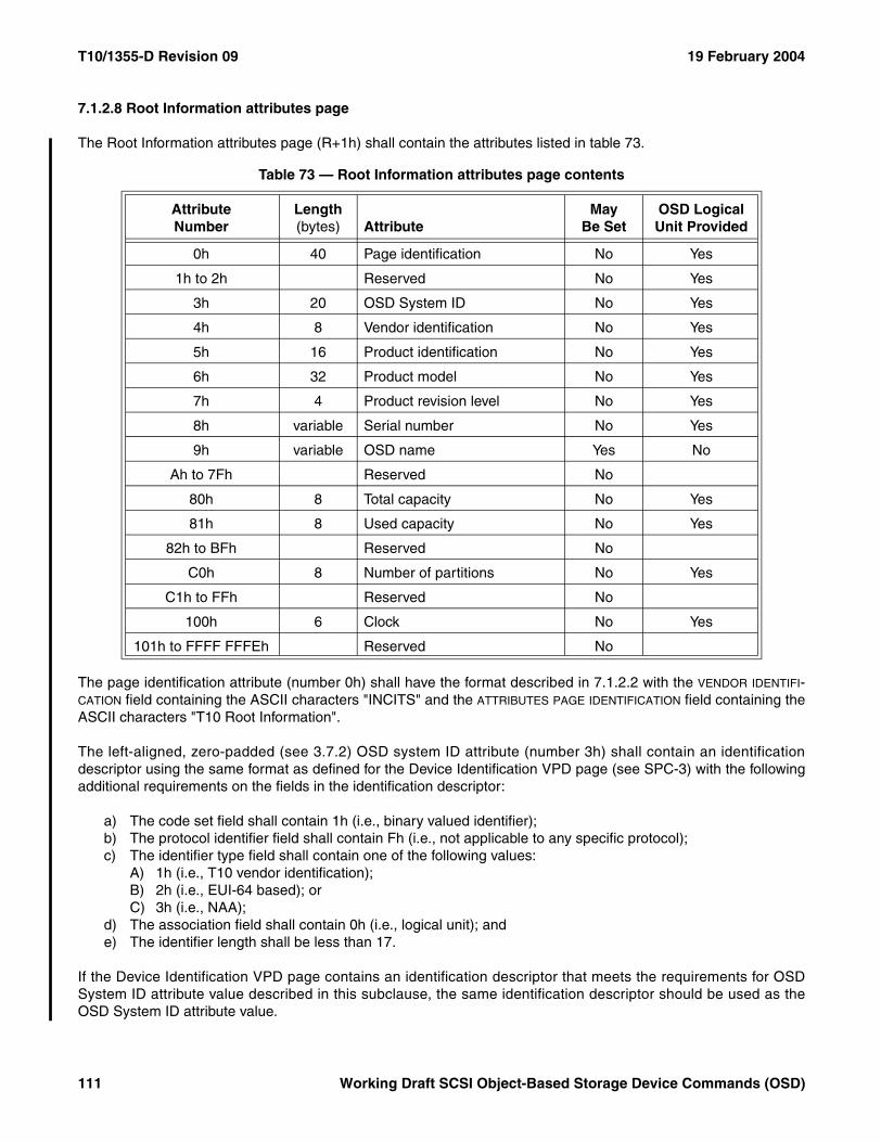
T10/1355-D Revision 09 19 February 2004
7.1.2.8 Root Information attributes page
The Root Information attributes page (R+1h) shall contain the attributes listed in table 73.
The page identification attribute (number 0h) shall have the format described in 7.1.2.2 with the VENDOR IDENTIFI-CATION field containing the ASCII characters "INCITS" and the ATTRIBUTES PAGE IDENTIFICATION field containing theASCII characters "T10 Root Information".
The left-aligned, zero-padded (see 3.7.2) OSD system ID attribute (number 3h) shall contain an identificationdescriptor using the same format as defined for the Device Identification VPD page (see SPC-3) with the followingadditional requirements on the fields in the identification descriptor:
a) The code set field shall contain 1h (i.e., binary valued identifier);b) The protocol identifier field shall contain Fh (i.e., not applicable to any specific protocol);c) The identifier type field shall contain one of the following values:
A) 1h (i.e., T10 vendor identification);B) 2h (i.e., EUI-64 based); orC) 3h (i.e., NAA);
d) The association field shall contain 0h (i.e., logical unit); ande) The identifier length shall be less than 17.
If the Device Identification VPD page contains an identification descriptor that meets the requirements for OSDSystem ID attribute value described in this subclause, the same identification descriptor should be used as theOSD System ID attribute value.
Table 73 — Root Information attributes page contents
AttributeNumber
Length (bytes) Attribute
May Be Set
OSD Logical Unit Provided
0h 40 Page identification No Yes
1h to 2h Reserved No Yes
3h 20 OSD System ID No Yes
4h 8 Vendor identification No Yes
5h 16 Product identification No Yes
6h 32 Product model No Yes
7h 4 Product revision level No Yes
8h variable Serial number No Yes
9h variable OSD name Yes No
Ah to 7Fh Reserved No
80h 8 Total capacity No Yes
81h 8 Used capacity No Yes
82h to BFh Reserved No
C0h 8 Number of partitions No Yes
C1h to FFh Reserved No
100h 6 Clock No Yes
101h to FFFF FFFEh Reserved No
111 Working Draft SCSI Object-Based Storage Device Commands (OSD)
19 February 2004 T10/1355-D Revision 09
The vendor identification attribute (number 4h) shall contain the vendor identification of the manufacturer of theOBSD (see 3.1.26) in the same format as the VENDOR IDENTIFICATION field in the standard INQUIRY data (seeSPC-3).
The product identification attribute (number 5h) shall contain the product identification of the OBSD in the sameformat as the PRODUCT IDENTIFICATION field in the standard INQUIRY data (see SPC-3).
The left-aligned, space-padded (see 3.7.2) product model attribute (number 6h) shall contain 32 bytes of ASCIIcharacters (see 3.7.1) identifying the model of the OBSD.
The product revision level attribute (number 7h) shall contain the product revision level of the OBSD in the sameformat as the PRODUCT REVISION LEVEL field in the standard INQUIRY data (see SPC-3).
The serial number attribute (number 8h) shall contain the product serial number of the OBSD in the same format asthe PRODUCT SERIAL NUMBER field in the Unit Serial Number VPD page (see SPC-3).
The OSD name attribute (number 9h) shall contain an identification of the OSD logical unit specified by the appli-cation client. The OSD name attribute length shall be set to zero by a FORMAT OSD command (see 6.8).
The total capacity attribute (number 80h) shall contain the total number of bytes on the OSD logical unit.
The used capacity attribute (number 81h) shall contain the number of bytes used by all root object attributes, parti-tions, collections and user objects stored by the OSD logical unit including attributes bytes for the partition, collec-tions, and user objects.
The number of partitions attribute (number C0h) shall contain the number partitions present in the OSD logical unit.
The clock attribute (number 100h) shall contain the current time in use by the OSD device server represented asthe count of the number of milliseconds elapsed since midnight, January 1, 1970 UT (see 3.1.47). The value shallbe identical to the value of the adjustable clock attribute in the Root Security attributes page (see 7.1.2.20).
If a set attributes list (see 5.2.1.3) contains an entry specifying the number of an attribute that table 73 states maynot be set, the command shall be terminated with a CHECK CONDITION status, with the sense key set toILLEGAL REQUEST and the additional sense code set to INVALID FIELD IN PARAMETER LIST. If the CDB SET
ATTRIBUTE NUMBER field (see 5.2.1.2) specifies the number of an attribute that table 73 states may not be set, thecommand shall be terminated with a CHECK CONDITION status, with the sense key set to ILLEGAL REQUESTand the additional sense code set to INVALID FIELD IN CDB.
Working Draft SCSI Object-Based Storage Device Commands (OSD) 112
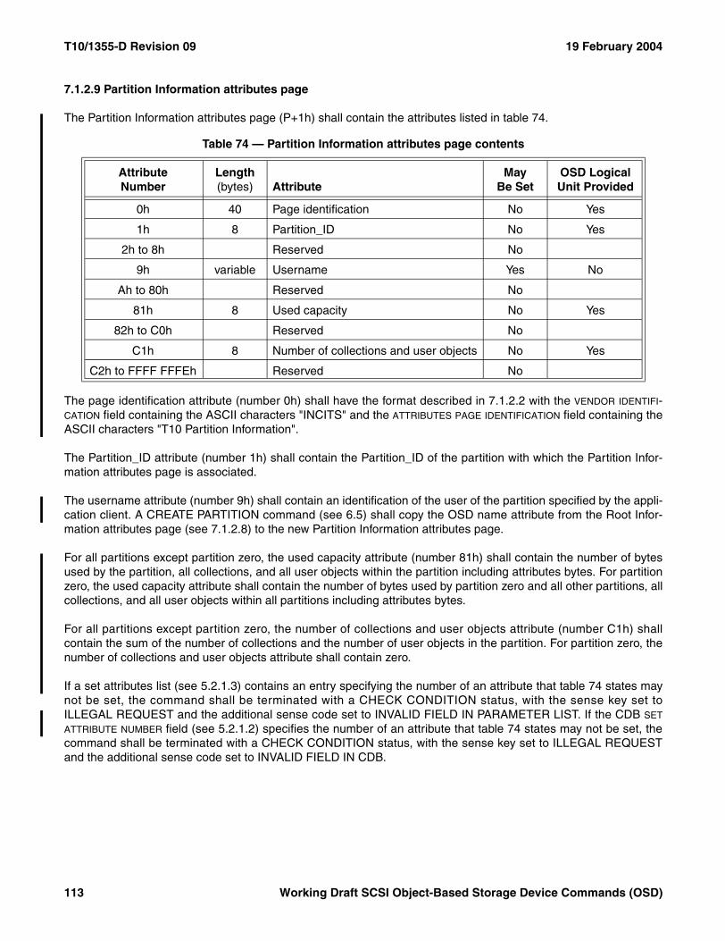
T10/1355-D Revision 09 19 February 2004
7.1.2.9 Partition Information attributes page
The Partition Information attributes page (P+1h) shall contain the attributes listed in table 74.
The page identification attribute (number 0h) shall have the format described in 7.1.2.2 with the VENDOR IDENTIFI-CATION field containing the ASCII characters "INCITS" and the ATTRIBUTES PAGE IDENTIFICATION field containing theASCII characters "T10 Partition Information".
The Partition_ID attribute (number 1h) shall contain the Partition_ID of the partition with which the Partition Infor-mation attributes page is associated.
The username attribute (number 9h) shall contain an identification of the user of the partition specified by the appli-cation client. A CREATE PARTITION command (see 6.5) shall copy the OSD name attribute from the Root Infor-mation attributes page (see 7.1.2.8) to the new Partition Information attributes page.
For all partitions except partition zero, the used capacity attribute (number 81h) shall contain the number of bytesused by the partition, all collections, and all user objects within the partition including attributes bytes. For partitionzero, the used capacity attribute shall contain the number of bytes used by partition zero and all other partitions, allcollections, and all user objects within all partitions including attributes bytes.
For all partitions except partition zero, the number of collections and user objects attribute (number C1h) shallcontain the sum of the number of collections and the number of user objects in the partition. For partition zero, thenumber of collections and user objects attribute shall contain zero.
If a set attributes list (see 5.2.1.3) contains an entry specifying the number of an attribute that table 74 states maynot be set, the command shall be terminated with a CHECK CONDITION status, with the sense key set toILLEGAL REQUEST and the additional sense code set to INVALID FIELD IN PARAMETER LIST. If the CDB SET
ATTRIBUTE NUMBER field (see 5.2.1.2) specifies the number of an attribute that table 74 states may not be set, thecommand shall be terminated with a CHECK CONDITION status, with the sense key set to ILLEGAL REQUESTand the additional sense code set to INVALID FIELD IN CDB.
Table 74 — Partition Information attributes page contents
AttributeNumber
Length (bytes) Attribute
May Be Set
OSD Logical Unit Provided
0h 40 Page identification No Yes
1h 8 Partition_ID No Yes
2h to 8h Reserved No
9h variable Username Yes No
Ah to 80h Reserved No
81h 8 Used capacity No Yes
82h to C0h Reserved No
C1h 8 Number of collections and user objects No Yes
C2h to FFFF FFFEh Reserved No
113 Working Draft SCSI Object-Based Storage Device Commands (OSD)
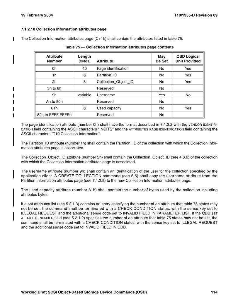
19 February 2004 T10/1355-D Revision 09
7.1.2.10 Collection Information attributes page
The Collection Information attributes page (C+1h) shall contain the attributes listed in table 75.
The page identification attribute (number 0h) shall have the format described in 7.1.2.2 with the VENDOR IDENTIFI-CATION field containing the ASCII characters "INCITS" and the ATTRIBUTES PAGE IDENTIFICATION field containing theASCII characters "T10 Collection Information".
The Partition_ID attribute (number 1h) shall contain the Partition_ID of the collection with which the Collection Infor-mation attributes page is associated.
The Collection_Object_ID attribute (number 2h) shall contain the Collection_Object_ID (see 4.6.6) of the collectionwith which the Collection Information attributes page is associated.
The username attribute (number 9h) shall contain an identification of the user for the collection specified by theapplication client. A CREATE COLLECTION command (see 6.5) shall copy the username attribute from thePartition Information attributes page (see 7.1.2.9) to the new Collection Information attributes page.
The used capacity attribute (number 81h) shall contain the number of bytes used by the collection includingattributes bytes.
If a set attributes list (see 5.2.1.3) contains an entry specifying the number of an attribute that table 75 states maynot be set, the command shall be terminated with a CHECK CONDITION status, with the sense key set toILLEGAL REQUEST and the additional sense code set to INVALID FIELD IN PARAMETER LIST. If the CDB SET
ATTRIBUTE NUMBER field (see 5.2.1.2) specifies the number of an attribute that table 75 states may not be set, thecommand shall be terminated with a CHECK CONDITION status, with the sense key set to ILLEGAL REQUESTand the additional sense code set to INVALID FIELD IN CDB.
Table 75 — Collection Information attributes page contents
AttributeNumber
Length (bytes) Attribute
May Be Set
OSD Logical Unit Provided
0h 40 Page identification No Yes
1h 8 Partition_ID No Yes
2h 8 Collection_Object_ID No Yes
3h to 8h Reserved No
9h variable Username Yes No
Ah to 80h Reserved No
81h 8 Used capacity No Yes
82h to FFFF FFFEh Reserved No
Working Draft SCSI Object-Based Storage Device Commands (OSD) 114
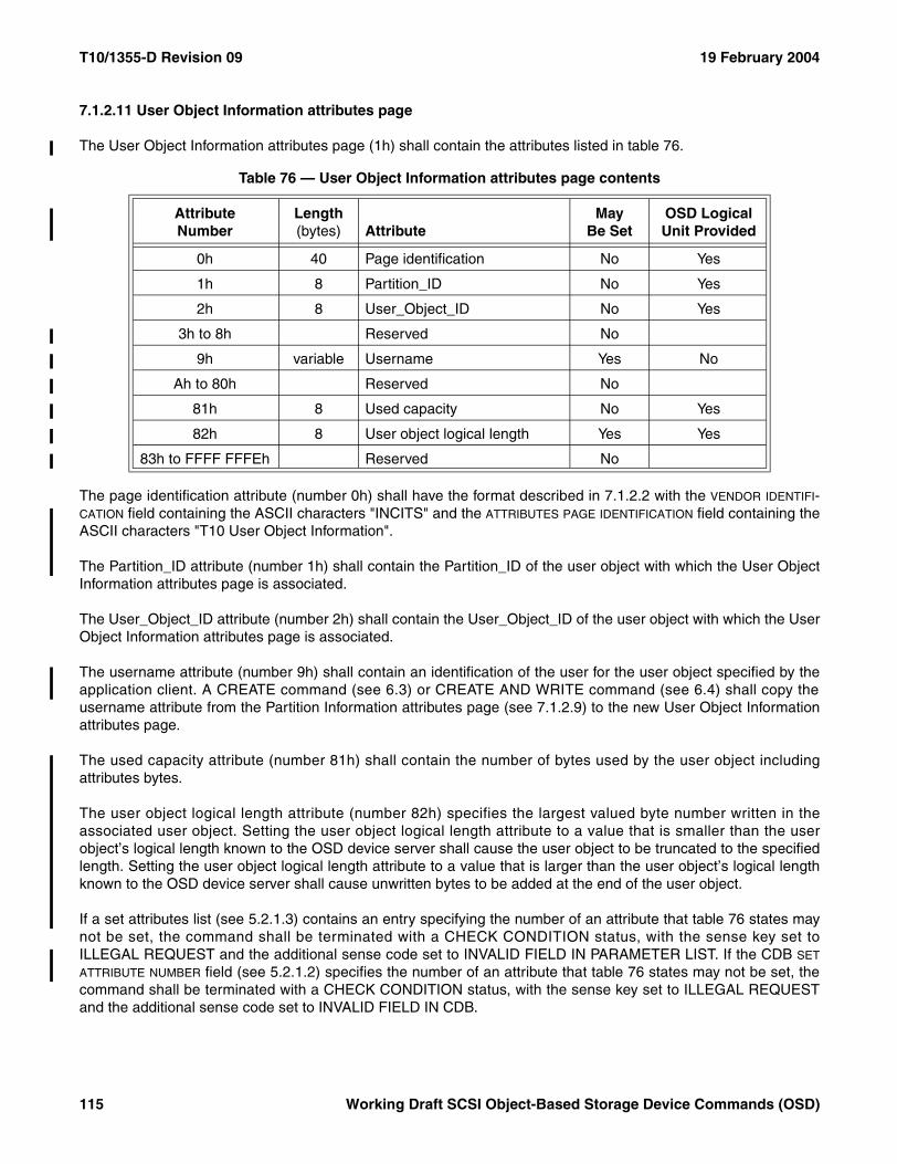
T10/1355-D Revision 09 19 February 2004
7.1.2.11 User Object Information attributes page
The User Object Information attributes page (1h) shall contain the attributes listed in table 76.
The page identification attribute (number 0h) shall have the format described in 7.1.2.2 with the VENDOR IDENTIFI-CATION field containing the ASCII characters "INCITS" and the ATTRIBUTES PAGE IDENTIFICATION field containing theASCII characters "T10 User Object Information".
The Partition_ID attribute (number 1h) shall contain the Partition_ID of the user object with which the User ObjectInformation attributes page is associated.
The User_Object_ID attribute (number 2h) shall contain the User_Object_ID of the user object with which the UserObject Information attributes page is associated.
The username attribute (number 9h) shall contain an identification of the user for the user object specified by theapplication client. A CREATE command (see 6.3) or CREATE AND WRITE command (see 6.4) shall copy theusername attribute from the Partition Information attributes page (see 7.1.2.9) to the new User Object Informationattributes page.
The used capacity attribute (number 81h) shall contain the number of bytes used by the user object includingattributes bytes.
The user object logical length attribute (number 82h) specifies the largest valued byte number written in theassociated user object. Setting the user object logical length attribute to a value that is smaller than the userobject’s logical length known to the OSD device server shall cause the user object to be truncated to the specifiedlength. Setting the user object logical length attribute to a value that is larger than the user object’s logical lengthknown to the OSD device server shall cause unwritten bytes to be added at the end of the user object.
If a set attributes list (see 5.2.1.3) contains an entry specifying the number of an attribute that table 76 states maynot be set, the command shall be terminated with a CHECK CONDITION status, with the sense key set toILLEGAL REQUEST and the additional sense code set to INVALID FIELD IN PARAMETER LIST. If the CDB SET
ATTRIBUTE NUMBER field (see 5.2.1.2) specifies the number of an attribute that table 76 states may not be set, thecommand shall be terminated with a CHECK CONDITION status, with the sense key set to ILLEGAL REQUESTand the additional sense code set to INVALID FIELD IN CDB.
Table 76 — User Object Information attributes page contents
AttributeNumber
Length (bytes) Attribute
May Be Set
OSD Logical Unit Provided
0h 40 Page identification No Yes
1h 8 Partition_ID No Yes
2h 8 User_Object_ID No Yes
3h to 8h Reserved No
9h variable Username Yes No
Ah to 80h Reserved No
81h 8 Used capacity No Yes
82h 8 User object logical length Yes Yes
83h to FFFF FFFEh Reserved No
115 Working Draft SCSI Object-Based Storage Device Commands (OSD)
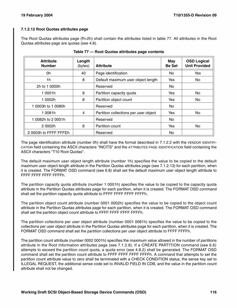
19 February 2004 T10/1355-D Revision 09
7.1.2.12 Root Quotas attributes page
The Root Quotas attributes page (R+2h) shall contain the attributes listed in table 77. All attributes in the RootQuotas attributes page are quotas (see 4.8).
The page identification attribute (number 0h) shall have the format described in 7.1.2.2 with the VENDOR IDENTIFI-CATION field containing the ASCII characters "INCITS" and the ATTRIBUTES PAGE IDENTIFICATION field containing theASCII characters "T10 Root Quotas".
The default maximum user object length attribute (number 1h) specifies the value to be copied to the defaultmaximum user object length attribute in the Partition Quotas attributes page (see 7.1.2.13) for each partition, whenit is created. The FORMAT OSD command (see 6.8) shall set the default maximum user object length attribute toFFFF FFFF FFFF FFFFh.
The partition capacity quota attribute (number 1 0001h) specifies the value to be copied to the capacity quotaattribute in the Partition Quotas attributes page for each partition, when it is created. The FORMAT OSD commandshall set the partition capacity quota attribute to FFFF FFFF FFFF FFFFh.
The partition object count attribute (number 0001 0002h) specifies the value to be copied to the object countattribute in the Partition Quotas attributes page for each partition, when it is created. The FORMAT OSD commandshall set the partition object count attribute to FFFF FFFF FFFF FFFFh.
The partition collections per user object attribute (number 0001 0081h) specifies the value to be copied to thecollections per user object attribute in the Partition Quotas attributes page for each partition, when it is created. TheFORMAT OSD command shall set the partition collections per user object attribute to FFFF FFFFh.
The partition count attribute (number 0002 0001h) specifies the maximum value allowed in the number of partitionsattribute in the Root Information attributes page (see 7.1.2.8). If a CREATE PARTITION command (see 6.6)attempts to exceed the partition count quota, a quota error (see 4.8.2) shall be generated. The FORMAT OSDcommand shall set the partition count attribute to FFFF FFFF FFFF FFFFh. A command that attempts to set thepartition count attribute value to zero shall be terminated with a CHECK CONDITION status, the sense key set toILLEGAL REQUEST, the additional sense code set to INVALID FIELD IN CDB, and the value in the partition countattribute shall not be changed.
Table 77 — Root Quotas attributes page contents
AttributeNumber
Length (bytes) Attribute
May Be Set
OSD Logical Unit Provided
0h 40 Page identification No Yes
1h 8 Default maximum user object length Yes No
2h to 1 0000h Reserved No
1 0001h 8 Partition capacity quota Yes No
1 0002h 8 Partition object count Yes No
1 0003h to 1 0080h Reserved No
1 0081h 4 Partition collections per user object Yes No
1 0082h to 2 0001h Reserved No
2 0002h 8 Partition count Yes No
2 0003h to FFFF FFFEh Reserved No
Working Draft SCSI Object-Based Storage Device Commands (OSD) 116
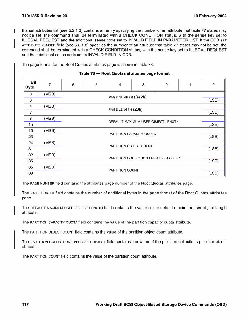
T10/1355-D Revision 09 19 February 2004
If a set attributes list (see 5.2.1.3) contains an entry specifying the number of an attribute that table 77 states maynot be set, the command shall be terminated with a CHECK CONDITION status, with the sense key set toILLEGAL REQUEST and the additional sense code set to INVALID FIELD IN PARAMETER LIST. If the CDB SET
ATTRIBUTE NUMBER field (see 5.2.1.2) specifies the number of an attribute that table 77 states may not be set, thecommand shall be terminated with a CHECK CONDITION status, with the sense key set to ILLEGAL REQUESTand the additional sense code set to INVALID FIELD IN CDB.
The page format for the Root Quotas attributes page is shown in table 78.
The PAGE NUMBER field contains the attributes page number of the Root Quotas attributes page.
The PAGE LENGTH field contains the number of additional bytes in the page format of the Root Quotas attributespage.
The DEFAULT MAXIMUM USER OBJECT LENGTH field contains the value of the default maximum user object lengthattribute.
The PARTITION CAPACITY QUOTA field contains the value of the partition capacity quota attribute.
The PARTITION OBJECT COUNT field contains the value of the partition object count attribute.
The PARTITION COLLECTIONS PER USER OBJECT field contains the value of the partition collections per user objectattribute.
The PARTITION COUNT field contains the value of the partition count attribute.
Table 78 — Root Quotas attributes page format
BitByte
7 6 5 4 3 2 1 0
0 (MSB)PAGE NUMBER (R+2h)
3 (LSB)
4 (MSB)PAGE LENGTH (20h)
7 (LSB)
8 (MSB)DEFAULT MAXIMUM USER OBJECT LENGTH
15 (LSB)
16 (MSB)PARTITION CAPACITY QUOTA
23 (LSB)
24 (MSB)PARTITION OBJECT COUNT
31 (LSB)
32 (MSB)PARTITION COLLECTIONS PER USER OBJECT
35 (LSB)
36 (MSB)PARTITION COUNT
39 (LSB)
117 Working Draft SCSI Object-Based Storage Device Commands (OSD)
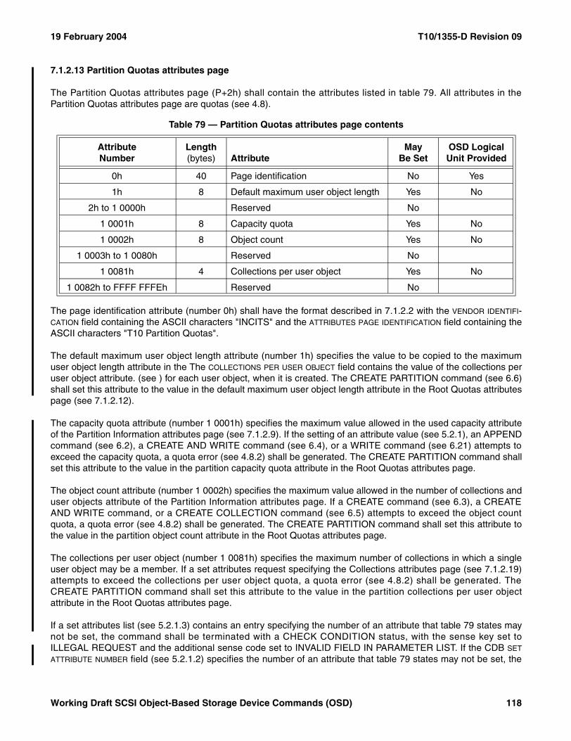
19 February 2004 T10/1355-D Revision 09
7.1.2.13 Partition Quotas attributes page
The Partition Quotas attributes page (P+2h) shall contain the attributes listed in table 79. All attributes in thePartition Quotas attributes page are quotas (see 4.8).
The page identification attribute (number 0h) shall have the format described in 7.1.2.2 with the VENDOR IDENTIFI-CATION field containing the ASCII characters "INCITS" and the ATTRIBUTES PAGE IDENTIFICATION field containing theASCII characters "T10 Partition Quotas".
The default maximum user object length attribute (number 1h) specifies the value to be copied to the maximumuser object length attribute in the The COLLECTIONS PER USER OBJECT field contains the value of the collections peruser object attribute. (see ) for each user object, when it is created. The CREATE PARTITION command (see 6.6)shall set this attribute to the value in the default maximum user object length attribute in the Root Quotas attributespage (see 7.1.2.12).
The capacity quota attribute (number 1 0001h) specifies the maximum value allowed in the used capacity attributeof the Partition Information attributes page (see 7.1.2.9). If the setting of an attribute value (see 5.2.1), an APPENDcommand (see 6.2), a CREATE AND WRITE command (see 6.4), or a WRITE command (see 6.21) attempts toexceed the capacity quota, a quota error (see 4.8.2) shall be generated. The CREATE PARTITION command shallset this attribute to the value in the partition capacity quota attribute in the Root Quotas attributes page.
The object count attribute (number 1 0002h) specifies the maximum value allowed in the number of collections anduser objects attribute of the Partition Information attributes page. If a CREATE command (see 6.3), a CREATEAND WRITE command, or a CREATE COLLECTION command (see 6.5) attempts to exceed the object countquota, a quota error (see 4.8.2) shall be generated. The CREATE PARTITION command shall set this attribute tothe value in the partition object count attribute in the Root Quotas attributes page.
The collections per user object (number 1 0081h) specifies the maximum number of collections in which a singleuser object may be a member. If a set attributes request specifying the Collections attributes page (see 7.1.2.19)attempts to exceed the collections per user object quota, a quota error (see 4.8.2) shall be generated. TheCREATE PARTITION command shall set this attribute to the value in the partition collections per user objectattribute in the Root Quotas attributes page.
If a set attributes list (see 5.2.1.3) contains an entry specifying the number of an attribute that table 79 states maynot be set, the command shall be terminated with a CHECK CONDITION status, with the sense key set toILLEGAL REQUEST and the additional sense code set to INVALID FIELD IN PARAMETER LIST. If the CDB SET
ATTRIBUTE NUMBER field (see 5.2.1.2) specifies the number of an attribute that table 79 states may not be set, the
Table 79 — Partition Quotas attributes page contents
AttributeNumber
Length (bytes) Attribute
May Be Set
OSD Logical Unit Provided
0h 40 Page identification No Yes
1h 8 Default maximum user object length Yes No
2h to 1 0000h Reserved No
1 0001h 8 Capacity quota Yes No
1 0002h 8 Object count Yes No
1 0003h to 1 0080h Reserved No
1 0081h 4 Collections per user object Yes No
1 0082h to FFFF FFFEh Reserved No
Working Draft SCSI Object-Based Storage Device Commands (OSD) 118
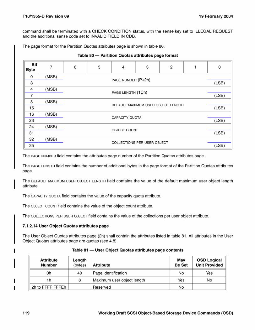
T10/1355-D Revision 09 19 February 2004
command shall be terminated with a CHECK CONDITION status, with the sense key set to ILLEGAL REQUESTand the additional sense code set to INVALID FIELD IN CDB.
The page format for the Partition Quotas attributes page is shown in table 80.
The PAGE NUMBER field contains the attributes page number of the Partition Quotas attributes page.
The PAGE LENGTH field contains the number of additional bytes in the page format of the Partition Quotas attributespage.
The DEFAULT MAXIMUM USER OBJECT LENGTH field contains the value of the default maximum user object lengthattribute.
The CAPACITY QUOTA field contains the value of the capacity quota attribute.
The OBJECT COUNT field contains the value of the object count attribute.
The COLLECTIONS PER USER OBJECT field contains the value of the collections per user object attribute.
7.1.2.14 User Object Quotas attributes page
The User Object Quotas attributes page (2h) shall contain the attributes listed in table 81. All attributes in the UserObject Quotas attributes page are quotas (see 4.8).
Table 80 — Partition Quotas attributes page format
BitByte
7 6 5 4 3 2 1 0
0 (MSB)PAGE NUMBER (P+2h)
3 (LSB)
4 (MSB)PAGE LENGTH (1Ch)
7 (LSB)
8 (MSB)DEFAULT MAXIMUM USER OBJECT LENGTH
15 (LSB)
16 (MSB)CAPACITY QUOTA
23 (LSB)
24 (MSB)OBJECT COUNT
31 (LSB)
32 (MSB)COLLECTIONS PER USER OBJECT
35 (LSB)
Table 81 — User Object Quotas attributes page contents
AttributeNumber
Length (bytes) Attribute
May Be Set
OSD Logical Unit Provided
0h 40 Page identification No Yes
1h 8 Maximum user object length Yes No
2h to FFFF FFFEh Reserved No
119 Working Draft SCSI Object-Based Storage Device Commands (OSD)
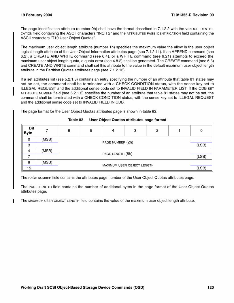
19 February 2004 T10/1355-D Revision 09
The page identification attribute (number 0h) shall have the format described in 7.1.2.2 with the VENDOR IDENTIFI-CATION field containing the ASCII characters "INCITS" and the ATTRIBUTES PAGE IDENTIFICATION field containing theASCII characters "T10 User Object Quotas".
The maximum user object length attribute (number 1h) specifies the maximum value the allow in the user objectlogical length attribute of the User Object Information attributes page (see 7.1.2.11). If an APPEND command (see6.2), a CREATE AND WRITE command (see 6.4), or a WRITE command (see 6.21) attempts to exceed themaximum user object length quota, a quota error (see 4.8.2) shall be generated. The CREATE command (see 6.3)and CREATE AND WRITE command shall set this attribute to the value in the default maximum user object lengthattribute in the Partition Quotas attributes page (see 7.1.2.13).
If a set attributes list (see 5.2.1.3) contains an entry specifying the number of an attribute that table 81 states maynot be set, the command shall be terminated with a CHECK CONDITION status, with the sense key set toILLEGAL REQUEST and the additional sense code set to INVALID FIELD IN PARAMETER LIST. If the CDB SET
ATTRIBUTE NUMBER field (see 5.2.1.2) specifies the number of an attribute that table 81 states may not be set, thecommand shall be terminated with a CHECK CONDITION status, with the sense key set to ILLEGAL REQUESTand the additional sense code set to INVALID FIELD IN CDB.
The page format for the User Object Quotas attributes page is shown in table 82.
The PAGE NUMBER field contains the attributes page number of the User Object Quotas attributes page.
The PAGE LENGTH field contains the number of additional bytes in the page format of the User Object Quotasattributes page.
The MAXIMUM USER OBJECT LENGTH field contains the value of the maximum user object length attribute.
Table 82 — User Object Quotas attributes page format
BitByte
7 6 5 4 3 2 1 0
0 (MSB)PAGE NUMBER (2h)
3 (LSB)
4 (MSB)PAGE LENGTH (8h)
7 (LSB)
8 (MSB)MAXIMUM USER OBJECT LENGTH
15 (LSB)
Working Draft SCSI Object-Based Storage Device Commands (OSD) 120
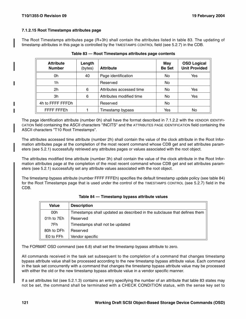
T10/1355-D Revision 09 19 February 2004
7.1.2.15 Root Timestamps attributes page
The Root Timestamps attributes page (R+3h) shall contain the attributes listed in table 83. The updating oftimestamp attributes in this page is controlled by the TIMESTAMPS CONTROL field (see 5.2.7) in the CDB.
The page identification attribute (number 0h) shall have the format described in 7.1.2.2 with the VENDOR IDENTIFI-CATION field containing the ASCII characters "INCITS" and the ATTRIBUTES PAGE IDENTIFICATION field containing theASCII characters "T10 Root Timestamps".
The attributes accessed time attribute (number 2h) shall contain the value of the clock attribute in the Root Infor-mation attributes page at the completion of the most recent command whose CDB get and set attributes param-eters (see 5.2.1) successfully retrieved any attributes pages or values associated with the root object.
The attributes modified time attribute (number 3h) shall contain the value of the clock attribute in the Root Infor-mation attributes page at the completion of the most recent command whose CDB get and set attributes param-eters (see 5.2.1) successfully set any attribute values associated with the root object.
The timestamp bypass attribute (number FFFF FFFEh) specifies the default timestamp update policy (see table 84)for the Root Timestamps page that is used under the control of the TIMESTAMPS CONTROL (see 5.2.7) field in theCDB.
The FORMAT OSD command (see 6.8) shall set the timestamp bypass attribute to zero.
All commands received in the task set subsequent to the completion of a command that changes timestampbypass attribute value shall be processed according to the new timestamp bypass attribute value. Each commandin the task set concurrently with a command that changes the timestamp bypass attribute value may be processedwith either the old or the new timestamp bypass attribute value in a vendor specific manner.
If a set attributes list (see 5.2.1.3) contains an entry specifying the number of an attribute that table 83 states maynot be set, the command shall be terminated with a CHECK CONDITION status, with the sense key set to
Table 83 — Root Timestamps attributes page contents
AttributeNumber
Length (bytes) Attribute
May Be Set
OSD Logical Unit Provided
0h 40 Page identification No Yes
1h Reserved No
2h 6 Attributes accessed time No Yes
3h 6 Attributes modified time No Yes
4h to FFFF FFFDh Reserved No
FFFF FFFEh 1 Timestamp bypass Yes No
Table 84 — Timestamp bypass attribute values
Value Description
00h Timestamps shall updated as described in the subclause that defines them
01h to 7Eh Reserved
7Fh Timestamps shall not be updated
80h to DFh Reserved
E0 to FFh Vendor specific
121 Working Draft SCSI Object-Based Storage Device Commands (OSD)
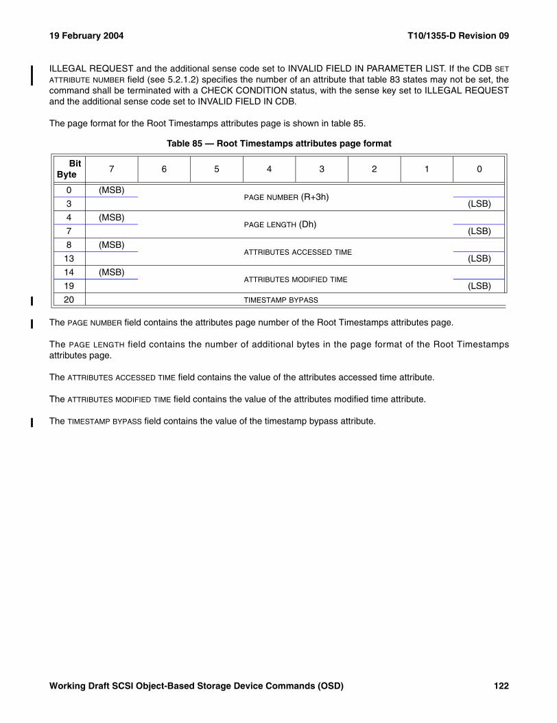
19 February 2004 T10/1355-D Revision 09
ILLEGAL REQUEST and the additional sense code set to INVALID FIELD IN PARAMETER LIST. If the CDB SET
ATTRIBUTE NUMBER field (see 5.2.1.2) specifies the number of an attribute that table 83 states may not be set, thecommand shall be terminated with a CHECK CONDITION status, with the sense key set to ILLEGAL REQUESTand the additional sense code set to INVALID FIELD IN CDB.
The page format for the Root Timestamps attributes page is shown in table 85.
The PAGE NUMBER field contains the attributes page number of the Root Timestamps attributes page.
The PAGE LENGTH field contains the number of additional bytes in the page format of the Root Timestampsattributes page.
The ATTRIBUTES ACCESSED TIME field contains the value of the attributes accessed time attribute.
The ATTRIBUTES MODIFIED TIME field contains the value of the attributes modified time attribute.
The TIMESTAMP BYPASS field contains the value of the timestamp bypass attribute.
Table 85 — Root Timestamps attributes page format
BitByte
7 6 5 4 3 2 1 0
0 (MSB)PAGE NUMBER (R+3h)
3 (LSB)
4 (MSB)PAGE LENGTH (Dh)
7 (LSB)
8 (MSB)ATTRIBUTES ACCESSED TIME
13 (LSB)
14 (MSB)ATTRIBUTES MODIFIED TIME
19 (LSB)
20 TIMESTAMP BYPASS
Working Draft SCSI Object-Based Storage Device Commands (OSD) 122
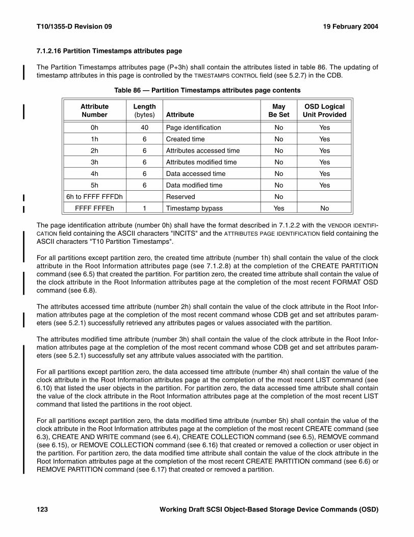
T10/1355-D Revision 09 19 February 2004
7.1.2.16 Partition Timestamps attributes page
The Partition Timestamps attributes page (P+3h) shall contain the attributes listed in table 86. The updating oftimestamp attributes in this page is controlled by the TIMESTAMPS CONTROL field (see 5.2.7) in the CDB.
The page identification attribute (number 0h) shall have the format described in 7.1.2.2 with the VENDOR IDENTIFI-CATION field containing the ASCII characters "INCITS" and the ATTRIBUTES PAGE IDENTIFICATION field containing theASCII characters "T10 Partition Timestamps".
For all partitions except partition zero, the created time attribute (number 1h) shall contain the value of the clockattribute in the Root Information attributes page (see 7.1.2.8) at the completion of the CREATE PARTITIONcommand (see 6.5) that created the partition. For partition zero, the created time attribute shall contain the value ofthe clock attribute in the Root Information attributes page at the completion of the most recent FORMAT OSDcommand (see 6.8).
The attributes accessed time attribute (number 2h) shall contain the value of the clock attribute in the Root Infor-mation attributes page at the completion of the most recent command whose CDB get and set attributes param-eters (see 5.2.1) successfully retrieved any attributes pages or values associated with the partition.
The attributes modified time attribute (number 3h) shall contain the value of the clock attribute in the Root Infor-mation attributes page at the completion of the most recent command whose CDB get and set attributes param-eters (see 5.2.1) successfully set any attribute values associated with the partition.
For all partitions except partition zero, the data accessed time attribute (number 4h) shall contain the value of theclock attribute in the Root Information attributes page at the completion of the most recent LIST command (see6.10) that listed the user objects in the partition. For partition zero, the data accessed time attribute shall containthe value of the clock attribute in the Root Information attributes page at the completion of the most recent LISTcommand that listed the partitions in the root object.
For all partitions except partition zero, the data modified time attribute (number 5h) shall contain the value of theclock attribute in the Root Information attributes page at the completion of the most recent CREATE command (see6.3), CREATE AND WRITE command (see 6.4), CREATE COLLECTION command (see 6.5), REMOVE command(see 6.15), or REMOVE COLLECTION command (see 6.16) that created or removed a collection or user object inthe partition. For partition zero, the data modified time attribute shall contain the value of the clock attribute in theRoot Information attributes page at the completion of the most recent CREATE PARTITION command (see 6.6) orREMOVE PARTITION command (see 6.17) that created or removed a partition.
Table 86 — Partition Timestamps attributes page contents
AttributeNumber
Length (bytes) Attribute
May Be Set
OSD Logical Unit Provided
0h 40 Page identification No Yes
1h 6 Created time No Yes
2h 6 Attributes accessed time No Yes
3h 6 Attributes modified time No Yes
4h 6 Data accessed time No Yes
5h 6 Data modified time No Yes
6h to FFFF FFFDh Reserved No
FFFF FFFEh 1 Timestamp bypass Yes No
123 Working Draft SCSI Object-Based Storage Device Commands (OSD)
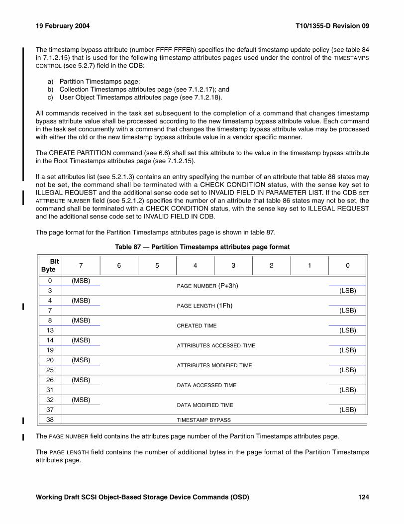
19 February 2004 T10/1355-D Revision 09
The timestamp bypass attribute (number FFFF FFFEh) specifies the default timestamp update policy (see table 84in 7.1.2.15) that is used for the following timestamp attributes pages used under the control of the TIMESTAMPS
CONTROL (see 5.2.7) field in the CDB:
a) Partition Timestamps page;b) Collection Timestamps attributes page (see 7.1.2.17); andc) User Object Timestamps attributes page (see 7.1.2.18).
All commands received in the task set subsequent to the completion of a command that changes timestampbypass attribute value shall be processed according to the new timestamp bypass attribute value. Each commandin the task set concurrently with a command that changes the timestamp bypass attribute value may be processedwith either the old or the new timestamp bypass attribute value in a vendor specific manner.
The CREATE PARTITION command (see 6.6) shall set this attribute to the value in the timestamp bypass attributein the Root Timestamps attributes page (see 7.1.2.15).
If a set attributes list (see 5.2.1.3) contains an entry specifying the number of an attribute that table 86 states maynot be set, the command shall be terminated with a CHECK CONDITION status, with the sense key set toILLEGAL REQUEST and the additional sense code set to INVALID FIELD IN PARAMETER LIST. If the CDB SET
ATTRIBUTE NUMBER field (see 5.2.1.2) specifies the number of an attribute that table 86 states may not be set, thecommand shall be terminated with a CHECK CONDITION status, with the sense key set to ILLEGAL REQUESTand the additional sense code set to INVALID FIELD IN CDB.
The page format for the Partition Timestamps attributes page is shown in table 87.
The PAGE NUMBER field contains the attributes page number of the Partition Timestamps attributes page.
The PAGE LENGTH field contains the number of additional bytes in the page format of the Partition Timestampsattributes page.
Table 87 — Partition Timestamps attributes page format
BitByte
7 6 5 4 3 2 1 0
0 (MSB)PAGE NUMBER (P+3h)
3 (LSB)
4 (MSB)PAGE LENGTH (1Fh)
7 (LSB)
8 (MSB)CREATED TIME
13 (LSB)
14 (MSB)ATTRIBUTES ACCESSED TIME
19 (LSB)
20 (MSB)ATTRIBUTES MODIFIED TIME
25 (LSB)
26 (MSB)DATA ACCESSED TIME
31 (LSB)
32 (MSB)DATA MODIFIED TIME
37 (LSB)
38 TIMESTAMP BYPASS
Working Draft SCSI Object-Based Storage Device Commands (OSD) 124
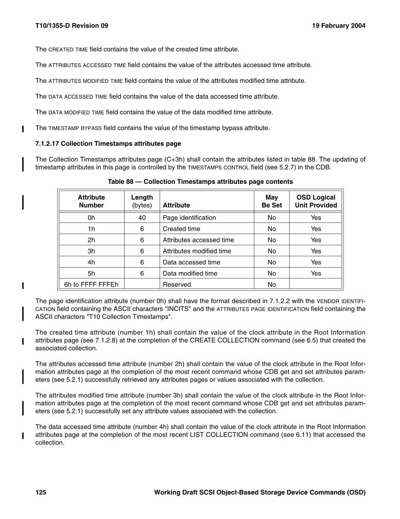
T10/1355-D Revision 09 19 February 2004
The CREATED TIME field contains the value of the created time attribute.
The ATTRIBUTES ACCESSED TIME field contains the value of the attributes accessed time attribute.
The ATTRIBUTES MODIFIED TIME field contains the value of the attributes modified time attribute.
The DATA ACCESSED TIME field contains the value of the data accessed time attribute.
The DATA MODIFIED TIME field contains the value of the data modified time attribute.
The TIMESTAMP BYPASS field contains the value of the timestamp bypass attribute.
7.1.2.17 Collection Timestamps attributes page
The Collection Timestamps attributes page (C+3h) shall contain the attributes listed in table 88. The updating oftimestamp attributes in this page is controlled by the TIMESTAMPS CONTROL field (see 5.2.7) in the CDB.
The page identification attribute (number 0h) shall have the format described in 7.1.2.2 with the VENDOR IDENTIFI-CATION field containing the ASCII characters "INCITS" and the ATTRIBUTES PAGE IDENTIFICATION field containing theASCII characters "T10 Collection Timestamps".
The created time attribute (number 1h) shall contain the value of the clock attribute in the Root Informationattributes page (see 7.1.2.8) at the completion of the CREATE COLLECTION command (see 6.5) that created theassociated collection.
The attributes accessed time attribute (number 2h) shall contain the value of the clock attribute in the Root Infor-mation attributes page at the completion of the most recent command whose CDB get and set attributes param-eters (see 5.2.1) successfully retrieved any attributes pages or values associated with the collection.
The attributes modified time attribute (number 3h) shall contain the value of the clock attribute in the Root Infor-mation attributes page at the completion of the most recent command whose CDB get and set attributes param-eters (see 5.2.1) successfully set any attribute values associated with the collection.
The data accessed time attribute (number 4h) shall contain the value of the clock attribute in the Root Informationattributes page at the completion of the most recent LIST COLLECTION command (see 6.11) that accessed thecollection.
Table 88 — Collection Timestamps attributes page contents
AttributeNumber
Length (bytes) Attribute
May Be Set
OSD Logical Unit Provided
0h 40 Page identification No Yes
1h 6 Created time No Yes
2h 6 Attributes accessed time No Yes
3h 6 Attributes modified time No Yes
4h 6 Data accessed time No Yes
5h 6 Data modified time No Yes
6h to FFFF FFFEh Reserved No
125 Working Draft SCSI Object-Based Storage Device Commands (OSD)
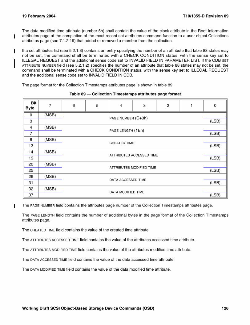
19 February 2004 T10/1355-D Revision 09
The data modified time attribute (number 5h) shall contain the value of the clock attribute in the Root Informationattributes page at the completion of the most recent set attributes command function to a user object Collectionsattributes page (see 7.1.2.19) that added or removed a member from the collection.
If a set attributes list (see 5.2.1.3) contains an entry specifying the number of an attribute that table 88 states maynot be set, the command shall be terminated with a CHECK CONDITION status, with the sense key set toILLEGAL REQUEST and the additional sense code set to INVALID FIELD IN PARAMETER LIST. If the CDB SET
ATTRIBUTE NUMBER field (see 5.2.1.2) specifies the number of an attribute that table 88 states may not be set, thecommand shall be terminated with a CHECK CONDITION status, with the sense key set to ILLEGAL REQUESTand the additional sense code set to INVALID FIELD IN CDB.
The page format for the Collection Timestamps attributes page is shown in table 89.
The PAGE NUMBER field contains the attributes page number of the Collection Timestamps attributes page.
The PAGE LENGTH field contains the number of additional bytes in the page format of the Collection Timestampsattributes page.
The CREATED TIME field contains the value of the created time attribute.
The ATTRIBUTES ACCESSED TIME field contains the value of the attributes accessed time attribute.
The ATTRIBUTES MODIFIED TIME field contains the value of the attributes modified time attribute.
The DATA ACCESSED TIME field contains the value of the data accessed time attribute.
The DATA MODIFIED TIME field contains the value of the data modified time attribute.
Table 89 — Collection Timestamps attributes page format
BitByte
7 6 5 4 3 2 1 0
0 (MSB)PAGE NUMBER (C+3h)
3 (LSB)
4 (MSB)PAGE LENGTH (1Eh)
7 (LSB)
8 (MSB)CREATED TIME
13 (LSB)
14 (MSB)ATTRIBUTES ACCESSED TIME
19 (LSB)
20 (MSB)ATTRIBUTES MODIFIED TIME
25 (LSB)
26 (MSB)DATA ACCESSED TIME
31 (LSB)
32 (MSB)DATA MODIFIED TIME
37 (LSB)
Working Draft SCSI Object-Based Storage Device Commands (OSD) 126
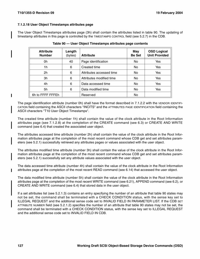
T10/1355-D Revision 09 19 February 2004
7.1.2.18 User Object Timestamps attributes page
The User Object Timestamps attributes page (3h) shall contain the attributes listed in table 90. The updating oftimestamp attributes in this page is controlled by the TIMESTAMPS CONTROL field (see 5.2.7) in the CDB.
The page identification attribute (number 0h) shall have the format described in 7.1.2.2 with the VENDOR IDENTIFI-CATION field containing the ASCII characters "INCITS" and the ATTRIBUTES PAGE IDENTIFICATION field containing theASCII characters "T10 User Object Timestamps".
The created time attribute (number 1h) shall contain the value of the clock attribute in the Root Informationattributes page (see 7.1.2.8) at the completion of the CREATE command (see 6.3) or CREATE AND WRITEcommand (see 6.4) that created the associated user object.
The attributes accessed time attribute (number 2h) shall contain the value of the clock attribute in the Root Infor-mation attributes page at the completion of the most recent command whose CDB get and set attributes param-eters (see 5.2.1) successfully retrieved any attributes pages or values associated with the user object.
The attributes modified time attribute (number 3h) shall contain the value of the clock attribute in the Root Infor-mation attributes page at the completion of the most recent command whose CDB get and set attributes param-eters (see 5.2.1) successfully set any attribute values associated with the user object.
The data accessed time attribute (number 4h) shall contain the value of the clock attribute in the Root Informationattributes page at the completion of the most recent READ command (see 6.14) that accessed the user object.
The data modified time attribute (number 5h) shall contain the value of the clock attribute in the Root Informationattributes page at the completion of the most recent WRITE command (see 6.21), APPEND command (see 6.2), orCREATE AND WRITE command (see 6.4) that stored data in the user object.
If a set attributes list (see 5.2.1.3) contains an entry specifying the number of an attribute that table 90 states maynot be set, the command shall be terminated with a CHECK CONDITION status, with the sense key set toILLEGAL REQUEST and the additional sense code set to INVALID FIELD IN PARAMETER LIST. If the CDB SET
ATTRIBUTE NUMBER field (see 5.2.1.2) specifies the number of an attribute that table 90 states may not be set, thecommand shall be terminated with a CHECK CONDITION status, with the sense key set to ILLEGAL REQUESTand the additional sense code set to INVALID FIELD IN CDB.
Table 90 — User Object Timestamps attributes page contents
AttributeNumber
Length (bytes) Attribute
May Be Set
OSD Logical Unit Provided
0h 40 Page identification No Yes
1h 6 Created time No Yes
2h 6 Attributes accessed time No Yes
3h 6 Attributes modified time No Yes
4h 6 Data accessed time No Yes
5h 6 Data modified time No Yes
6h to FFFF FFFEh Reserved No
127 Working Draft SCSI Object-Based Storage Device Commands (OSD)

19 February 2004 T10/1355-D Revision 09
The page format for the User Object Timestamps attributes page is shown in table 91.
The PAGE NUMBER field contains the attributes page number of the User Object Timestamps attributes page.
The PAGE LENGTH field contains the number of additional bytes in the page format of the User Object Timestampsattributes page.
The CREATED TIME field contains the value of the created time attribute.
The ATTRIBUTES ACCESSED TIME field contains the value of the attributes accessed time attribute.
The ATTRIBUTES MODIFIED TIME field contains the value of the attributes modified time attribute.
The DATA ACCESSED TIME field contains the value of the data accessed time attribute.
The DATA MODIFIED TIME field contains the value of the data modified time attribute.
7.1.2.19 Collections attributes page
The Collections attributes page (4h) shall contain the attributes listed in table 92.
Table 91 — User Object Timestamps attributes page format
BitByte
7 6 5 4 3 2 1 0
0 (MSB)PAGE NUMBER (3h)
3 (LSB)
4 (MSB)PAGE LENGTH (1Eh)
7 (LSB)
8 (MSB)CREATED TIME
13 (LSB)
14 (MSB)ATTRIBUTES ACCESSED TIME
19 (LSB)
20 (MSB)ATTRIBUTES MODIFIED TIME
25 (LSB)
26 (MSB)DATA ACCESSED TIME
31 (LSB)
32 (MSB)DATA MODIFIED TIME
37 (LSB)
Table 92 — Collections attributes page contents
AttributeNumber
Length (bytes) Attribute
May Be Set
OSD Logical Unit Provided
0h 40 Page identification No Yes
1h to FFFF FF00h 0 or 8 Collection pointer Yes No
FFFF FF01h to FFFF FFFEh Reserved No
Working Draft SCSI Object-Based Storage Device Commands (OSD) 128
T10/1355-D Revision 09 19 February 2004
The page identification attribute (number 0h) shall have the format described in 7.1.2.2 with the VENDOR IDENTIFI-CATION field containing the ASCII characters "INCITS" and the ATTRIBUTES PAGE IDENTIFICATION field containing theASCII characters "T10 Collections".
Each collection pointer attribute (1h to FFFF FF00h) may be:
a) A zero length attribute (i.e., contain no value); or b) The Collection_Object_ID of a collection (see 4.6.6) to which the user object belongs.
A user object is made a member of a collection by setting one of its collection pointer attribute values to theCollection_Object_ID of that collection.
A user object is removed from the membership of a collection by:
a) Changing the collection pointer attribute identifying that collection to have a length of zero; orb) Setting the collection pointer attribute identifying that collection to the Collection_Object_ID of a different
collection.
The command shall be terminated with a CHECK CONDITION status, with the sense key set to ILLEGALREQUEST and the additional sense code set to INVALID FIELD IN PARAMETER LIST if a set attributes list (see5.2.1.3) contains an entry that sets:
a) The same Collection_Object_ID in more than one collection pointer attribute;b) A collection pointer attribute to a value that is not a Collection_Object_ID; orc) A collection pointer attribute to any length other than zero or eight.
The command shall be terminated with a CHECK CONDITION status, with the sense key set to ILLEGALREQUEST and the additional sense code set to INVALID FIELD IN CDB if:
a) The CDB SET ATTRIBUTE NUMBER field and the set attributes data specified by the SET ATTRIBUTES OFFSET
field (see 5.2.1.2) sets:A) The same Collection_Object_ID in more than one collection pointer attribute; orB) A collection pointer attribute to a value that is not a Collection_Object_ID;or
b) The CDB SET ATTRIBUTE LENGTH field contains a value other than zero or eight.
If a set attributes list contains an entry specifying the number of an attribute that table 92 states may not be set, thecommand shall be terminated with a CHECK CONDITION status, with the sense key set to ILLEGAL REQUESTand the additional sense code set to INVALID FIELD IN PARAMETER LIST. If the CDB SET ATTRIBUTE NUMBER fieldspecifies the number of an attribute that table 92 states may not be set, the command shall be terminated with aCHECK CONDITION status, with the sense key set to ILLEGAL REQUEST and the additional sense code set toINVALID FIELD IN CDB.
129 Working Draft SCSI Object-Based Storage Device Commands (OSD)
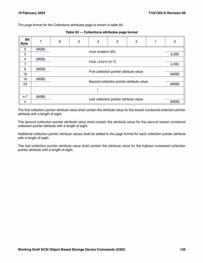
19 February 2004 T10/1355-D Revision 09
The page format for the Collections attributes page is shown in table 93.
The first collection pointer attribute value shall contain the attribute value for the lowest numbered collection pointerattribute with a length of eight.
The second collection pointer attribute value shall contain the attribute value for the second lowest numberedcollection pointer attribute with a length of eight.
Additional collection pointer attribute values shall be added to the page format for each collection pointer attributewith a length of eight.
The last collection pointer attribute value shall contain the attribute value for the highest numbered collectionpointer attribute with a length of eight.
Table 93 — Collections attributes page format
BitByte
7 6 5 4 3 2 1 0
0 (MSB)PAGE NUMBER (4h)
3 (LSB)
4 (MSB)PAGE LENGTH (n-7)
7 (LSB)
8 (MSB)First collection pointer attribute value
15 (MSB)
16 (MSB)Second collection pointer attribute value
23 (MSB) ...
n-7 (MSB)Last collection pointer attribute value
n (MSB)
Working Draft SCSI Object-Based Storage Device Commands (OSD) 130
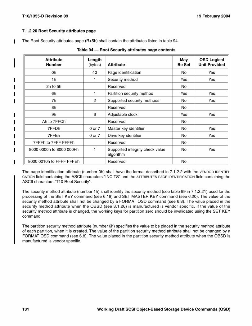
T10/1355-D Revision 09 19 February 2004
7.1.2.20 Root Security attributes page
The Root Security attributes page (R+5h) shall contain the attributes listed in table 94.
The page identification attribute (number 0h) shall have the format described in 7.1.2.2 with the VENDOR IDENTIFI-CATION field containing the ASCII characters "INCITS" and the ATTRIBUTES PAGE IDENTIFICATION field containing theASCII characters "T10 Root Security".
The security method attribute (number 1h) shall identify the security method (see table 99 in 7.1.2.21) used for theprocessing of the SET KEY command (see 6.19) and SET MASTER KEY command (see 6.20). The value of thesecurity method attribute shall not be changed by a FORMAT OSD command (see 6.8). The value placed in thesecurity method attribute when the OBSD (see 3.1.26) is manufactured is vendor specific. If the value of thesecurity method attribute is changed, the working keys for partition zero should be invalidated using the SET KEYcommand.
The partition security method attribute (number 6h) specifies the value to be placed in the security method attributeof each partition, when it is created. The value of the partition security method attribute shall not be changed by aFORMAT OSD command (see 6.8). The value placed in the partition security method attribute when the OBSD ismanufactured is vendor specific.
Table 94 — Root Security attributes page contents
AttributeNumber
Length (bytes) Attribute
May Be Set
OSD Logical Unit Provided
0h 40 Page identification No Yes
1h 1 Security method Yes Yes
2h to 5h Reserved No
6h 1 Partition security method Yes Yes
7h 2 Supported security methods No Yes
8h Reserved No
9h 6 Adjustable clock Yes Yes
Ah to 7FFCh Reserved No
7FFDh 0 or 7 Master key identifier No Yes
7FFEh 0 or 7 Drive key identifier No Yes
7FFFh to 7FFF FFFFh Reserved No
8000 0000h to 8000 000Fh 1 Supported integrity check value algorithm
No Yes
8000 0010h to FFFF FFFEh Reserved No
131 Working Draft SCSI Object-Based Storage Device Commands (OSD)
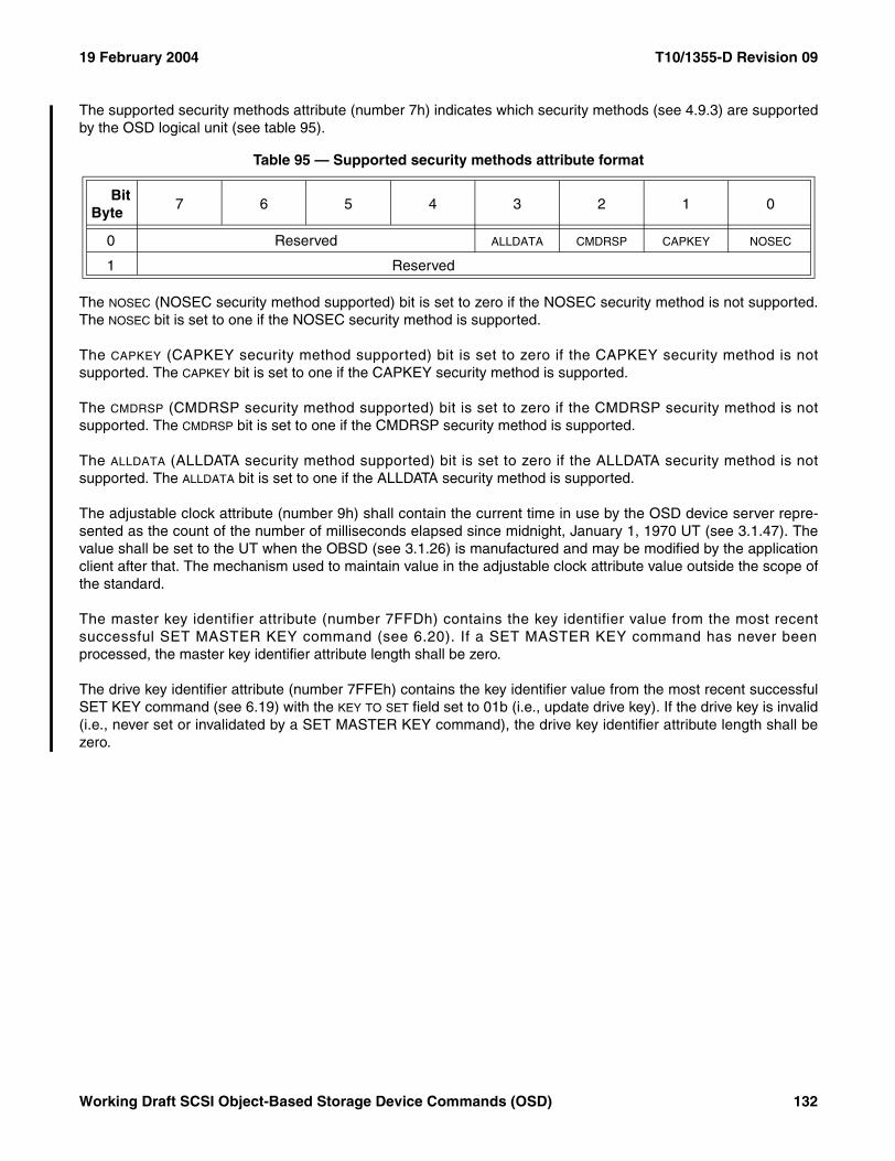
19 February 2004 T10/1355-D Revision 09
The supported security methods attribute (number 7h) indicates which security methods (see 4.9.3) are supportedby the OSD logical unit (see table 95).
The NOSEC (NOSEC security method supported) bit is set to zero if the NOSEC security method is not supported.The NOSEC bit is set to one if the NOSEC security method is supported.
The CAPKEY (CAPKEY security method supported) bit is set to zero if the CAPKEY security method is notsupported. The CAPKEY bit is set to one if the CAPKEY security method is supported.
The CMDRSP (CMDRSP security method supported) bit is set to zero if the CMDRSP security method is notsupported. The CMDRSP bit is set to one if the CMDRSP security method is supported.
The ALLDATA (ALLDATA security method supported) bit is set to zero if the ALLDATA security method is notsupported. The ALLDATA bit is set to one if the ALLDATA security method is supported.
The adjustable clock attribute (number 9h) shall contain the current time in use by the OSD device server repre-sented as the count of the number of milliseconds elapsed since midnight, January 1, 1970 UT (see 3.1.47). Thevalue shall be set to the UT when the OBSD (see 3.1.26) is manufactured and may be modified by the applicationclient after that. The mechanism used to maintain value in the adjustable clock attribute value outside the scope ofthe standard.
The master key identifier attribute (number 7FFDh) contains the key identifier value from the most recentsuccessful SET MASTER KEY command (see 6.20). If a SET MASTER KEY command has never beenprocessed, the master key identifier attribute length shall be zero.
The drive key identifier attribute (number 7FFEh) contains the key identifier value from the most recent successfulSET KEY command (see 6.19) with the KEY TO SET field set to 01b (i.e., update drive key). If the drive key is invalid(i.e., never set or invalidated by a SET MASTER KEY command), the drive key identifier attribute length shall bezero.
Table 95 — Supported security methods attribute format
BitByte
7 6 5 4 3 2 1 0
0 Reserved ALLDATA CMDRSP CAPKEY NOSEC
1 Reserved
Working Draft SCSI Object-Based Storage Device Commands (OSD) 132
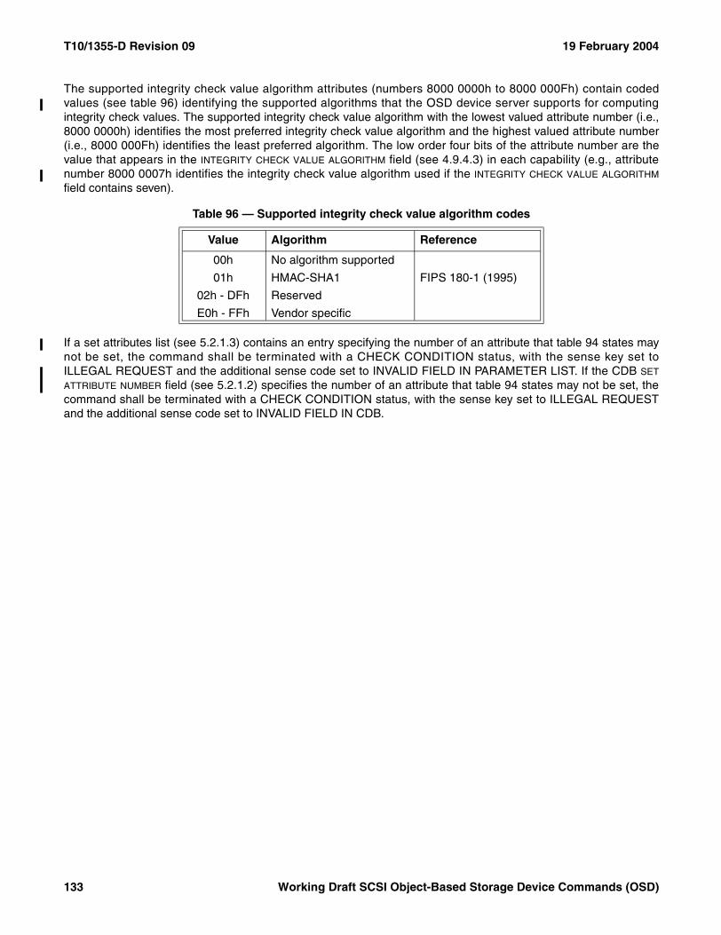
T10/1355-D Revision 09 19 February 2004
The supported integrity check value algorithm attributes (numbers 8000 0000h to 8000 000Fh) contain codedvalues (see table 96) identifying the supported algorithms that the OSD device server supports for computingintegrity check values. The supported integrity check value algorithm with the lowest valued attribute number (i.e.,8000 0000h) identifies the most preferred integrity check value algorithm and the highest valued attribute number(i.e., 8000 000Fh) identifies the least preferred algorithm. The low order four bits of the attribute number are thevalue that appears in the INTEGRITY CHECK VALUE ALGORITHM field (see 4.9.4.3) in each capability (e.g., attributenumber 8000 0007h identifies the integrity check value algorithm used if the INTEGRITY CHECK VALUE ALGORITHM
field contains seven).
If a set attributes list (see 5.2.1.3) contains an entry specifying the number of an attribute that table 94 states maynot be set, the command shall be terminated with a CHECK CONDITION status, with the sense key set toILLEGAL REQUEST and the additional sense code set to INVALID FIELD IN PARAMETER LIST. If the CDB SET
ATTRIBUTE NUMBER field (see 5.2.1.2) specifies the number of an attribute that table 94 states may not be set, thecommand shall be terminated with a CHECK CONDITION status, with the sense key set to ILLEGAL REQUESTand the additional sense code set to INVALID FIELD IN CDB.
Table 96 — Supported integrity check value algorithm codes
Value Algorithm Reference
00h No algorithm supported
01h HMAC-SHA1 FIPS 180-1 (1995)
02h - DFh Reserved
E0h - FFh Vendor specific
133 Working Draft SCSI Object-Based Storage Device Commands (OSD)
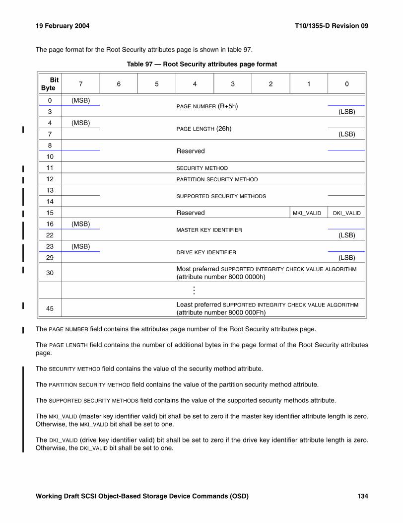
19 February 2004 T10/1355-D Revision 09
The page format for the Root Security attributes page is shown in table 97.
The PAGE NUMBER field contains the attributes page number of the Root Security attributes page.
The PAGE LENGTH field contains the number of additional bytes in the page format of the Root Security attributespage.
The SECURITY METHOD field contains the value of the security method attribute.
The PARTITION SECURITY METHOD field contains the value of the partition security method attribute.
The SUPPORTED SECURITY METHODS field contains the value of the supported security methods attribute.
The MKI_VALID (master key identifier valid) bit shall be set to zero if the master key identifier attribute length is zero.Otherwise, the MKI_VALID bit shall be set to one.
The DKI_VALID (drive key identifier valid) bit shall be set to zero if the drive key identifier attribute length is zero.Otherwise, the DKI_VALID bit shall be set to one.
Table 97 — Root Security attributes page format
BitByte
7 6 5 4 3 2 1 0
0 (MSB)PAGE NUMBER (R+5h)
3 (LSB)
4 (MSB)PAGE LENGTH (26h)
7 (LSB)
8Reserved
10
11 SECURITY METHOD
12 PARTITION SECURITY METHOD
13 SUPPORTED SECURITY METHODS
14
15 Reserved MKI_VALID DKI_VALID
16 (MSB)MASTER KEY IDENTIFIER
22 (LSB)
23 (MSB)DRIVE KEY IDENTIFIER
29 (LSB)
30Most preferred SUPPORTED INTEGRITY CHECK VALUE ALGORITHM
(attribute number 8000 0000h)...
45Least preferred SUPPORTED INTEGRITY CHECK VALUE ALGORITHM
(attribute number 8000 000Fh)
Working Draft SCSI Object-Based Storage Device Commands (OSD) 134
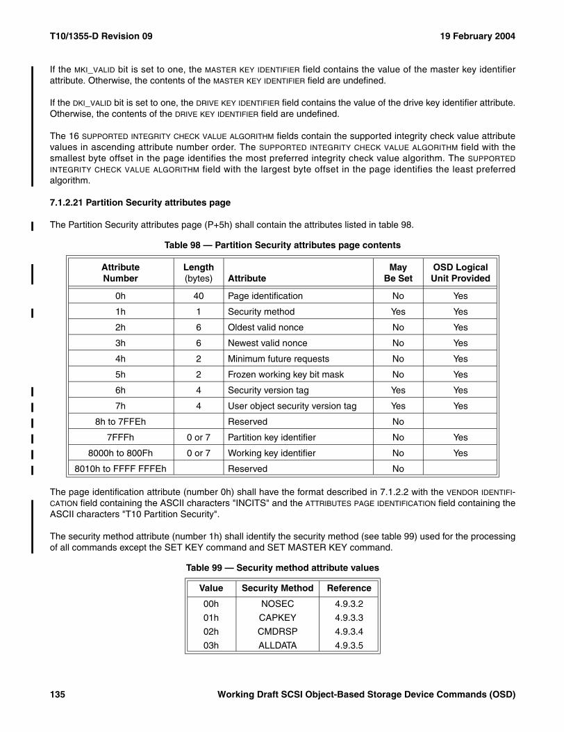
T10/1355-D Revision 09 19 February 2004
If the MKI_VALID bit is set to one, the MASTER KEY IDENTIFIER field contains the value of the master key identifierattribute. Otherwise, the contents of the MASTER KEY IDENTIFIER field are undefined.
If the DKI_VALID bit is set to one, the DRIVE KEY IDENTIFIER field contains the value of the drive key identifier attribute.Otherwise, the contents of the DRIVE KEY IDENTIFIER field are undefined.
The 16 SUPPORTED INTEGRITY CHECK VALUE ALGORITHM fields contain the supported integrity check value attributevalues in ascending attribute number order. The SUPPORTED INTEGRITY CHECK VALUE ALGORITHM field with thesmallest byte offset in the page identifies the most preferred integrity check value algorithm. The SUPPORTED
INTEGRITY CHECK VALUE ALGORITHM field with the largest byte offset in the page identifies the least preferredalgorithm.
7.1.2.21 Partition Security attributes page
The Partition Security attributes page (P+5h) shall contain the attributes listed in table 98.
The page identification attribute (number 0h) shall have the format described in 7.1.2.2 with the VENDOR IDENTIFI-CATION field containing the ASCII characters "INCITS" and the ATTRIBUTES PAGE IDENTIFICATION field containing theASCII characters "T10 Partition Security".
The security method attribute (number 1h) shall identify the security method (see table 99) used for the processingof all commands except the SET KEY command and SET MASTER KEY command.
Table 98 — Partition Security attributes page contents
AttributeNumber
Length (bytes) Attribute
May Be Set
OSD Logical Unit Provided
0h 40 Page identification No Yes
1h 1 Security method Yes Yes
2h 6 Oldest valid nonce No Yes
3h 6 Newest valid nonce No Yes
4h 2 Minimum future requests No Yes
5h 2 Frozen working key bit mask No Yes
6h 4 Security version tag Yes Yes
7h 4 User object security version tag Yes Yes
8h to 7FFEh Reserved No
7FFFh 0 or 7 Partition key identifier No Yes
8000h to 800Fh 0 or 7 Working key identifier No Yes
8010h to FFFF FFFEh Reserved No
Table 99 — Security method attribute values
Value Security Method Reference
00h NOSEC 4.9.3.2
01h CAPKEY 4.9.3.3
02h CMDRSP 4.9.3.4
03h ALLDATA 4.9.3.5
135 Working Draft SCSI Object-Based Storage Device Commands (OSD)
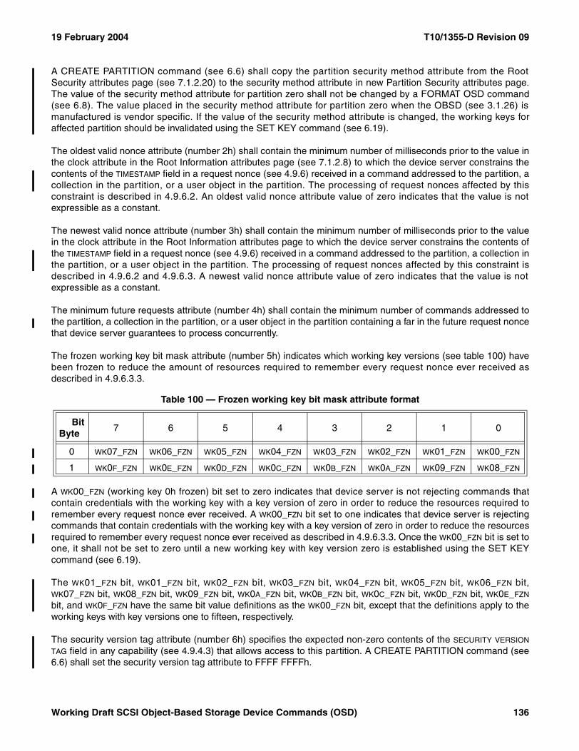
19 February 2004 T10/1355-D Revision 09
A CREATE PARTITION command (see 6.6) shall copy the partition security method attribute from the RootSecurity attributes page (see 7.1.2.20) to the security method attribute in new Partition Security attributes page.The value of the security method attribute for partition zero shall not be changed by a FORMAT OSD command(see 6.8). The value placed in the security method attribute for partition zero when the OBSD (see 3.1.26) ismanufactured is vendor specific. If the value of the security method attribute is changed, the working keys foraffected partition should be invalidated using the SET KEY command (see 6.19).
The oldest valid nonce attribute (number 2h) shall contain the minimum number of milliseconds prior to the value inthe clock attribute in the Root Information attributes page (see 7.1.2.8) to which the device server constrains thecontents of the TIMESTAMP field in a request nonce (see 4.9.6) received in a command addressed to the partition, acollection in the partition, or a user object in the partition. The processing of request nonces affected by thisconstraint is described in 4.9.6.2. An oldest valid nonce attribute value of zero indicates that the value is notexpressible as a constant.
The newest valid nonce attribute (number 3h) shall contain the minimum number of milliseconds prior to the valuein the clock attribute in the Root Information attributes page to which the device server constrains the contents ofthe TIMESTAMP field in a request nonce (see 4.9.6) received in a command addressed to the partition, a collection inthe partition, or a user object in the partition. The processing of request nonces affected by this constraint isdescribed in 4.9.6.2 and 4.9.6.3. A newest valid nonce attribute value of zero indicates that the value is notexpressible as a constant.
The minimum future requests attribute (number 4h) shall contain the minimum number of commands addressed tothe partition, a collection in the partition, or a user object in the partition containing a far in the future request noncethat device server guarantees to process concurrently.
The frozen working key bit mask attribute (number 5h) indicates which working key versions (see table 100) havebeen frozen to reduce the amount of resources required to remember every request nonce ever received asdescribed in 4.9.6.3.3.
A WK00_FZN (working key 0h frozen) bit set to zero indicates that device server is not rejecting commands thatcontain credentials with the working key with a key version of zero in order to reduce the resources required toremember every request nonce ever received. A WK00_FZN bit set to one indicates that device server is rejectingcommands that contain credentials with the working key with a key version of zero in order to reduce the resourcesrequired to remember every request nonce ever received as described in 4.9.6.3.3. Once the WK00_FZN bit is set toone, it shall not be set to zero until a new working key with key version zero is established using the SET KEYcommand (see 6.19).
The WK01_FZN bit, WK01_FZN bit, WK02_FZN bit, WK03_FZN bit, WK04_FZN bit, WK05_FZN bit, WK06_FZN bit,WK07_FZN bit, WK08_FZN bit, WK09_FZN bit, WK0A_FZN bit, WK0B_FZN bit, WK0C_FZN bit, WK0D_FZN bit, WK0E_FZN
bit, and WK0F_FZN have the same bit value definitions as the WK00_FZN bit, except that the definitions apply to theworking keys with key versions one to fifteen, respectively.
The security version tag attribute (number 6h) specifies the expected non-zero contents of the SECURITY VERSION
TAG field in any capability (see 4.9.4.3) that allows access to this partition. A CREATE PARTITION command (see6.6) shall set the security version tag attribute to FFFF FFFFh.
Table 100 — Frozen working key bit mask attribute format
BitByte
7 6 5 4 3 2 1 0
0 WK07_FZN WK06_FZN WK05_FZN WK04_FZN WK03_FZN WK02_FZN WK01_FZN WK00_FZN
1 WK0F_FZN WK0E_FZN WK0D_FZN WK0C_FZN WK0B_FZN WK0A_FZN WK09_FZN WK08_FZN
Working Draft SCSI Object-Based Storage Device Commands (OSD) 136
T10/1355-D Revision 09 19 February 2004
If a set attributes list (see 5.2.1.3) contains an request to set the security version tag attribute to zero, the commandshall be terminated with a CHECK CONDITION status, with the sense key set to ILLEGAL REQUEST and theadditional sense code set to INVALID FIELD IN PARAMETER LIST. If the CDB SET ATTRIBUTE NUMBER fieldcontains 6h (i.e., the security version tag attribute) and the set attributes data specified by the SET ATTRIBUTES
OFFSET field (see 5.2.1.2) contains zero, the command shall be terminated with a CHECK CONDITION status, withthe sense key set to ILLEGAL REQUEST and the additional sense code set to INVALID FIELD IN CDB.
The user object security version tag attribute (number 7h) specifies the value to be placed in the security versiontag attribute of each collection or user object, when it is created. A CREATE PARTITION command (see 6.6) shallset the user object security version tag attribute to FFFF FFFFh.
If a set attributes list (see 5.2.1.3) contains an request to set the user object security version tag attribute to zero,the command shall be terminated with a CHECK CONDITION status, with the sense key set to ILLEGALREQUEST and the additional sense code set to INVALID FIELD IN PARAMETER LIST. If the CDB SET ATTRIBUTE
NUMBER field contains 7h (i.e., the user object security version tag attribute) and the set attributes data specified bythe SET ATTRIBUTES OFFSET field (see 5.2.1.2) contains zero, the command shall be terminated with a CHECKCONDITION status, with the sense key set to ILLEGAL REQUEST and the additional sense code set to INVALIDFIELD IN CDB.
The partition key identifier attribute (number 7FFFh) contains the key identifier value from the most recentsuccessful SET KEY command (see 6.19) with the KEY TO SET field set to 10b (i.e., update partition key). If thepartition key is invalid (i.e., never set, invalidated by a SET MASTER KEY command (see 6.20), or invalidated by aSET KEY command), the partition key identifier attribute length shall be zero.
The working key identifier attributes (numbers 8000h to 800Fh) contain the key identifier value from the mostrecent successful SET KEY command with:
a) The KEY TO SET field set to 11b (i.e., update working key); andb) The KEY VERSION field set to the attribute number minus 8000h (e.g., a version key of three sets attribute
8003h and a version key of eight sets attribute 8008h).
If a working key is invalid (i.e., never set, invalidated by a SET MASTER KEY command, or invalidated by a SETKEY command), the working key identifier attribute length for the associated working key shall be zero.
If a set attributes list contains an entry specifying the number of an attribute that table 98 states may not be set, thecommand shall be terminated with a CHECK CONDITION status, with the sense key set to ILLEGAL REQUESTand the additional sense code set to INVALID FIELD IN PARAMETER LIST. If the CDB SET ATTRIBUTE NUMBER fieldspecifies the number of an attribute that table 98 states may not be set, the command shall be terminated with aCHECK CONDITION status, with the sense key set to ILLEGAL REQUEST and the additional sense code set toINVALID FIELD IN CDB.
137 Working Draft SCSI Object-Based Storage Device Commands (OSD)
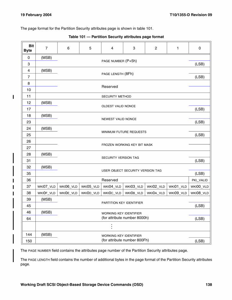
19 February 2004 T10/1355-D Revision 09
The page format for the Partition Security attributes page is shown in table 101.
The PAGE NUMBER field contains the attributes page number of the Partition Security attributes page.
The PAGE LENGTH field contains the number of additional bytes in the page format of the Partition Security attributespage.
Table 101 — Partition Security attributes page format
BitByte
7 6 5 4 3 2 1 0
0 (MSB)PAGE NUMBER (P+5h)
3 (LSB)
4 (MSB)PAGE LENGTH (8Fh)
7 (LSB)
8Reserved
10
11 SECURITY METHOD
12 (MSB)OLDEST VALID NONCE
17 (LSB)
18 (MSB)NEWEST VALID NONCE
23 (LSB)
24 (MSB)MINIMUM FUTURE REQUESTS
25 (LSB)
26FROZEN WORKING KEY BIT MASK
27
28 (MSB)SECURITY VERSION TAG
31 (LSB)
32 (MSB)USER OBJECT SECURITY VERSION TAG
35 (LSB)
36 Reserved PKI_VALID
37 WKI07_VLD WKI06_VLD WKI05_VLD WKI04_VLD WKI03_VLD WKI02_VLD WKI01_VLD WKI00_VLD
38 WKI0F_VLD WKI0E_VLD WKI0D_VLD WKI0C_VLD WKI0B_VLD WKI0A_VLD WKI09_VLD WKI08_VLD
39 (MSB)PARTITION KEY IDENTIFIER
45 (LSB)
46 (MSB) WORKING KEY IDENTIFIER
(for attribute number 8000h)
64 (LSB)...
144 (MSB) WORKING KEY IDENTIFIER
(for attribute number 800Fh)
150 (LSB)
Working Draft SCSI Object-Based Storage Device Commands (OSD) 138
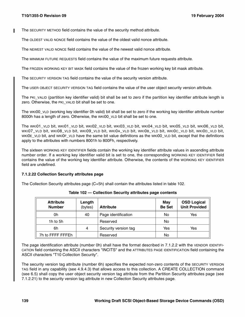
T10/1355-D Revision 09 19 February 2004
The SECURITY METHOD field contains the value of the security method attribute.
The OLDEST VALID NONCE field contains the value of the oldest valid nonce attribute.
The NEWEST VALID NONCE field contains the value of the newest valid nonce attribute.
The MINIMUM FUTURE REQUESTS field contains the value of the maximum future requests attribute.
The FROZEN WORKING KEY BIT MASK field contains the value of the frozen working key bit mask attribute.
The SECURITY VERSION TAG field contains the value of the security version attribute.
The USER OBJECT SECURITY VERSION TAG field contains the value of the user object security version attribute.
The PKI_VALID (partition key identifier valid) bit shall be set to zero if the partition key identifier attribute length iszero. Otherwise, the PKI_VALID bit shall be set to one.
The WKI00_VLD (working key identifier 0h valid) bit shall be set to zero if the working key identifier attribute number8000h has a length of zero. Otherwise, the WKI00_VLD bit shall be set to one.
The WKI01_VLD bit, WKI01_VLD bit, WKI02_VLD bit, WKI03_VLD bit, WKI04_VLD bit, WKI05_VLD bit, WKI06_VLD bit,WKI07_VLD bit, WKI08_VLD bit, WKI09_VLD bit, WKI0A_VLD bit, WKI0B_VLD bit, WKI0C_VLD bit, WKI0D_VLD bit,WKI0E_VLD bit, and WKI0F_VLD have the same bit value definitions as the WKI00_VLD bit, except that the definitionsapply to the attributes with numbers 8001h to 800Fh, respectively.
The sixteen WORKING KEY IDENTIFIER fields contain the working key identifier attribute values in ascending attributenumber order. If a working key identifier valid bit is set to one, the corresponding WORKING KEY IDENTIFIER fieldcontains the value of the working key identifier attribute. Otherwise, the contents of the WORKING KEY IDENTIFIER
field are undefined.
7.1.2.22 Collection Security attributes page
The Collection Security attributes page (C+5h) shall contain the attributes listed in table 102.
The page identification attribute (number 0h) shall have the format described in 7.1.2.2 with the VENDOR IDENTIFI-CATION field containing the ASCII characters "INCITS" and the ATTRIBUTES PAGE IDENTIFICATION field containing theASCII characters "T10 Collection Security".
The security version tag attribute (number 6h) specifies the expected non-zero contents of the SECURITY VERSION
TAG field in any capability (see 4.9.4.3) that allows access to this collection. A CREATE COLLECTION command(see 6.5) shall copy the user object security version tag attribute from the Partition Security attributes page (see7.1.2.21) to the security version tag attribute in new Collection Security attributes page.
Table 102 — Collection Security attributes page contents
AttributeNumber
Length (bytes) Attribute
May Be Set
OSD Logical Unit Provided
0h 40 Page identification No Yes
1h to 5h Reserved No
6h 4 Security version tag Yes Yes
7h to FFFF FFFEh Reserved No
139 Working Draft SCSI Object-Based Storage Device Commands (OSD)
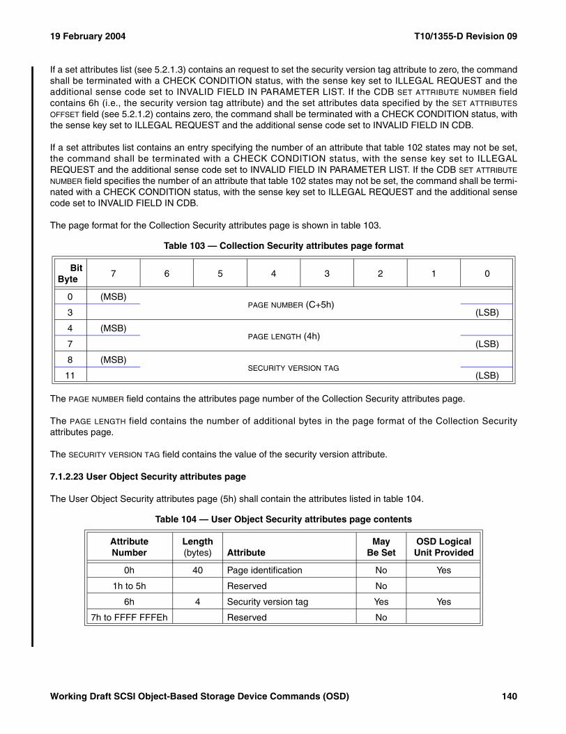
19 February 2004 T10/1355-D Revision 09
If a set attributes list (see 5.2.1.3) contains an request to set the security version tag attribute to zero, the commandshall be terminated with a CHECK CONDITION status, with the sense key set to ILLEGAL REQUEST and theadditional sense code set to INVALID FIELD IN PARAMETER LIST. If the CDB SET ATTRIBUTE NUMBER fieldcontains 6h (i.e., the security version tag attribute) and the set attributes data specified by the SET ATTRIBUTES
OFFSET field (see 5.2.1.2) contains zero, the command shall be terminated with a CHECK CONDITION status, withthe sense key set to ILLEGAL REQUEST and the additional sense code set to INVALID FIELD IN CDB.
If a set attributes list contains an entry specifying the number of an attribute that table 102 states may not be set,the command shall be terminated with a CHECK CONDITION status, with the sense key set to ILLEGALREQUEST and the additional sense code set to INVALID FIELD IN PARAMETER LIST. If the CDB SET ATTRIBUTE
NUMBER field specifies the number of an attribute that table 102 states may not be set, the command shall be termi-nated with a CHECK CONDITION status, with the sense key set to ILLEGAL REQUEST and the additional sensecode set to INVALID FIELD IN CDB.
The page format for the Collection Security attributes page is shown in table 103.
The PAGE NUMBER field contains the attributes page number of the Collection Security attributes page.
The PAGE LENGTH field contains the number of additional bytes in the page format of the Collection Securityattributes page.
The SECURITY VERSION TAG field contains the value of the security version attribute.
7.1.2.23 User Object Security attributes page
The User Object Security attributes page (5h) shall contain the attributes listed in table 104.
Table 103 — Collection Security attributes page format
BitByte
7 6 5 4 3 2 1 0
0 (MSB)PAGE NUMBER (C+5h)
3 (LSB)
4 (MSB)PAGE LENGTH (4h)
7 (LSB)
8 (MSB)SECURITY VERSION TAG
11 (LSB)
Table 104 — User Object Security attributes page contents
AttributeNumber
Length (bytes) Attribute
May Be Set
OSD Logical Unit Provided
0h 40 Page identification No Yes
1h to 5h Reserved No
6h 4 Security version tag Yes Yes
7h to FFFF FFFEh Reserved No
Working Draft SCSI Object-Based Storage Device Commands (OSD) 140
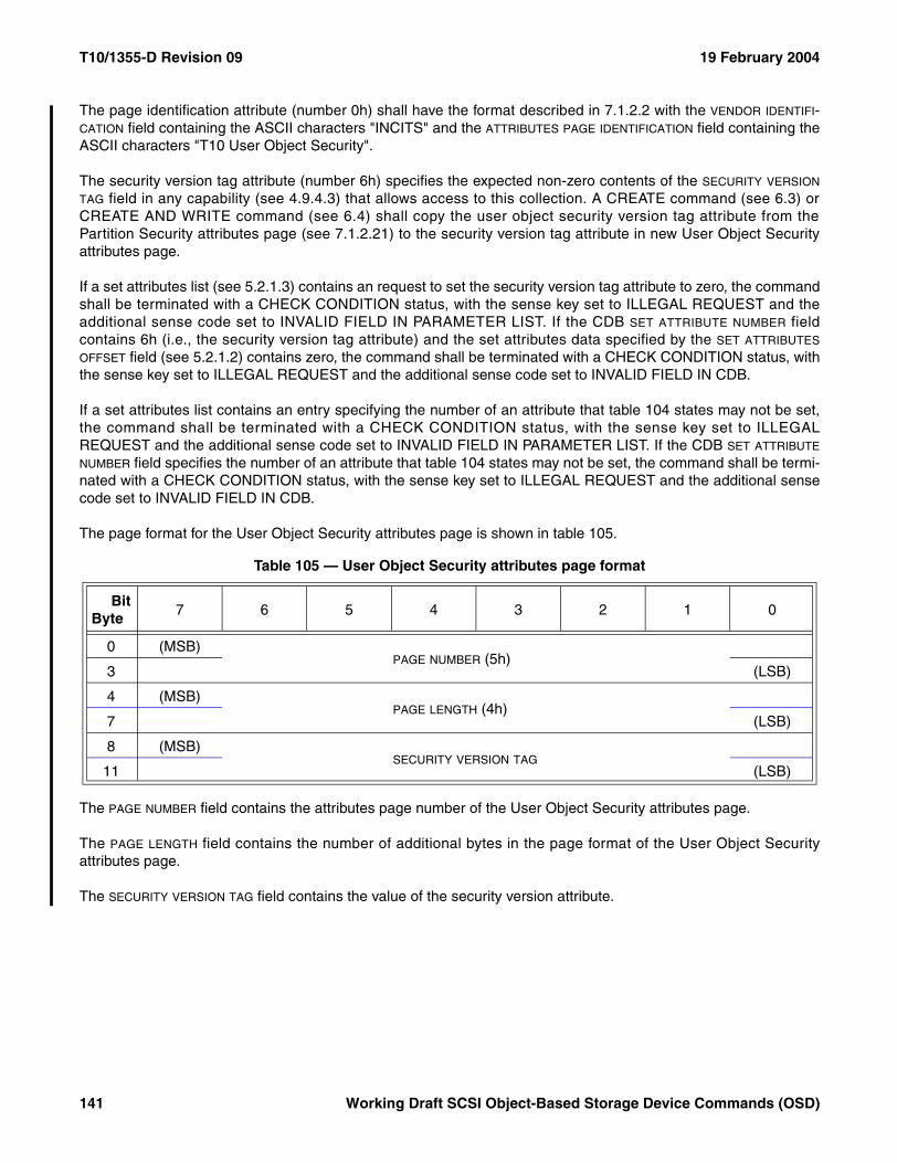
T10/1355-D Revision 09 19 February 2004
The page identification attribute (number 0h) shall have the format described in 7.1.2.2 with the VENDOR IDENTIFI-CATION field containing the ASCII characters "INCITS" and the ATTRIBUTES PAGE IDENTIFICATION field containing theASCII characters "T10 User Object Security".
The security version tag attribute (number 6h) specifies the expected non-zero contents of the SECURITY VERSION
TAG field in any capability (see 4.9.4.3) that allows access to this collection. A CREATE command (see 6.3) orCREATE AND WRITE command (see 6.4) shall copy the user object security version tag attribute from thePartition Security attributes page (see 7.1.2.21) to the security version tag attribute in new User Object Securityattributes page.
If a set attributes list (see 5.2.1.3) contains an request to set the security version tag attribute to zero, the commandshall be terminated with a CHECK CONDITION status, with the sense key set to ILLEGAL REQUEST and theadditional sense code set to INVALID FIELD IN PARAMETER LIST. If the CDB SET ATTRIBUTE NUMBER fieldcontains 6h (i.e., the security version tag attribute) and the set attributes data specified by the SET ATTRIBUTES
OFFSET field (see 5.2.1.2) contains zero, the command shall be terminated with a CHECK CONDITION status, withthe sense key set to ILLEGAL REQUEST and the additional sense code set to INVALID FIELD IN CDB.
If a set attributes list contains an entry specifying the number of an attribute that table 104 states may not be set,the command shall be terminated with a CHECK CONDITION status, with the sense key set to ILLEGALREQUEST and the additional sense code set to INVALID FIELD IN PARAMETER LIST. If the CDB SET ATTRIBUTE
NUMBER field specifies the number of an attribute that table 104 states may not be set, the command shall be termi-nated with a CHECK CONDITION status, with the sense key set to ILLEGAL REQUEST and the additional sensecode set to INVALID FIELD IN CDB.
The page format for the User Object Security attributes page is shown in table 105.
The PAGE NUMBER field contains the attributes page number of the User Object Security attributes page.
The PAGE LENGTH field contains the number of additional bytes in the page format of the User Object Securityattributes page.
The SECURITY VERSION TAG field contains the value of the security version attribute.
Table 105 — User Object Security attributes page format
BitByte
7 6 5 4 3 2 1 0
0 (MSB)PAGE NUMBER (5h)
3 (LSB)
4 (MSB)PAGE LENGTH (4h)
7 (LSB)
8 (MSB)SECURITY VERSION TAG
11 (LSB)
141 Working Draft SCSI Object-Based Storage Device Commands (OSD)
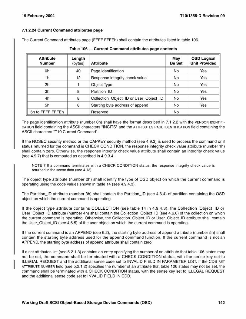
19 February 2004 T10/1355-D Revision 09
7.1.2.24 Current Command attributes page
The Current Command attributes page (FFFF FFFEh) shall contain the attributes listed in table 106.
The page identification attribute (number 0h) shall have the format described in 7.1.2.2 with the VENDOR IDENTIFI-CATION field containing the ASCII characters "INCITS" and the ATTRIBUTES PAGE IDENTIFICATION field containing theASCII characters "T10 Current Command".
If the NOSEC security method or the CAPKEY security method (see 4.9.3) is used to process the command or ifstatus returned for the command is CHECK CONDITION, the response integrity check value attribute (number 1h)shall contain zero. Otherwise, the response integrity check value attribute shall contain an integrity check value(see 4.9.7) that is computed as described in 4.9.3.4.
NOTE 7 If a command terminates with a CHECK CONDITION status, the response integrity check value isreturned in the sense data (see 4.13).
The object type attribute (number 2h) shall identify the type of OSD object on which the current command isoperating using the code values shown in table 14 (see 4.9.4.3).
The Partition_ID attribute (number 3h) shall contain the Partition_ID (see 4.6.4) of partition containing the OSDobject on which the current command is operating.
If the object type attribute contains COLLECTION (see table 14 in 4.9.4.3), the Collection_Object_ID orUser_Object_ID attribute (number 4h) shall contain the Collection_Object_ID (see 4.6.6) of the collection on whichthe current command is operating. Otherwise, the Collection_Object_ID or User_Object_ID attribute shall containthe User_Object_ID (see 4.6.5) of the user object on which the current command is operating.
If the current command is an APPEND (see 6.2), the starting byte address of append attribute (number 5h) shallcontain the starting byte address used for the append command function. If the current command is not anAPPEND, the starting byte address of append attribute shall contain zero.
If a set attributes list (see 5.2.1.3) contains an entry specifying the number of an attribute that table 106 states maynot be set, the command shall be terminated with a CHECK CONDITION status, with the sense key set toILLEGAL REQUEST and the additional sense code set to INVALID FIELD IN PARAMETER LIST. If the CDB SET
ATTRIBUTE NUMBER field (see 5.2.1.2) specifies the number of an attribute that table 106 states may not be set, thecommand shall be terminated with a CHECK CONDITION status, with the sense key set to ILLEGAL REQUESTand the additional sense code set to INVALID FIELD IN CDB.
Table 106 — Current Command attributes page contents
AttributeNumber
Length (bytes) Attribute
May Be Set
OSD Logical Unit Provided
0h 40 Page identification No Yes
1h 12 Response integrity check value No Yes
2h 1 Object Type No Yes
3h 8 Partition_ID No Yes
4h 8 Collection_Object_ID or User_Object_ID No Yes
5h 8 Starting byte address of append No Yes
6h to FFFF FFFEh Reserved No
Working Draft SCSI Object-Based Storage Device Commands (OSD) 142
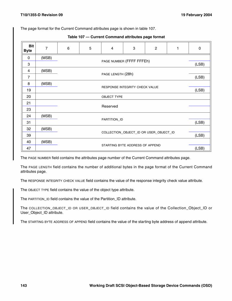
T10/1355-D Revision 09 19 February 2004
The page format for the Current Command attributes page is shown in table 107.
The PAGE NUMBER field contains the attributes page number of the Current Command attributes page.
The PAGE LENGTH field contains the number of additional bytes in the page format of the Current Commandattributes page.
The RESPONSE INTEGRITY CHECK VALUE field contains the value of the response integrity check value attribute.
The OBJECT TYPE field contains the value of the object type attribute.
The PARTITION_ID field contains the value of the Partition_ID attribute.
The COLLECTION_OBJECT_ID OR USER_OBJECT_ID field contains the value of the Collection_Object_ID orUser_Object_ID attribute.
The STARTING BYTE ADDRESS OF APPEND field contains the value of the starting byte address of append attribute.
Table 107 — Current Command attributes page format
BitByte
7 6 5 4 3 2 1 0
0 (MSB)PAGE NUMBER (FFFF FFFEh)
3 (LSB)
4 (MSB)PAGE LENGTH (28h)
7 (LSB)
8 (MSB)RESPONSE INTEGRITY CHECK VALUE
19 (LSB)
20 OBJECT TYPE
21Reserved
23
24 (MSB)PARTITION_ID
31 (LSB)
32 (MSB)COLLECTION_OBJECT_ID OR USER_OBJECT_ID
39 (LSB)
40 (MSB)STARTING BYTE ADDRESS OF APPEND
47 (LSB)
143 Working Draft SCSI Object-Based Storage Device Commands (OSD)
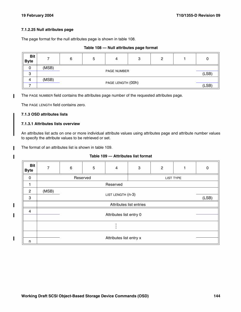
19 February 2004 T10/1355-D Revision 09
7.1.2.25 Null attributes page
The page format for the null attributes page is shown in table 108.
The PAGE NUMBER field contains the attributes page number of the requested attributes page.
The PAGE LENGTH field contains zero.
7.1.3 OSD attributes lists
7.1.3.1 Attributes lists overview
An attributes list acts on one or more individual attribute values using attributes page and attribute number valuesto specify the attribute values to be retrieved or set.
The format of an attributes list is shown in table 109.
Table 108 — Null attributes page format
BitByte
7 6 5 4 3 2 1 0
0 (MSB)PAGE NUMBER
3 (LSB)
4 (MSB)PAGE LENGTH (00h)
7 (LSB)
Table 109 — Attributes list format
BitByte
7 6 5 4 3 2 1 0
0 Reserved LIST TYPE
1 Reserved
2 (MSB)LIST LENGTH (n-3)
3 (LSB)
Attributes list entries
4Attributes list entry 0
...
Attributes list entry xn
Working Draft SCSI Object-Based Storage Device Commands (OSD) 144
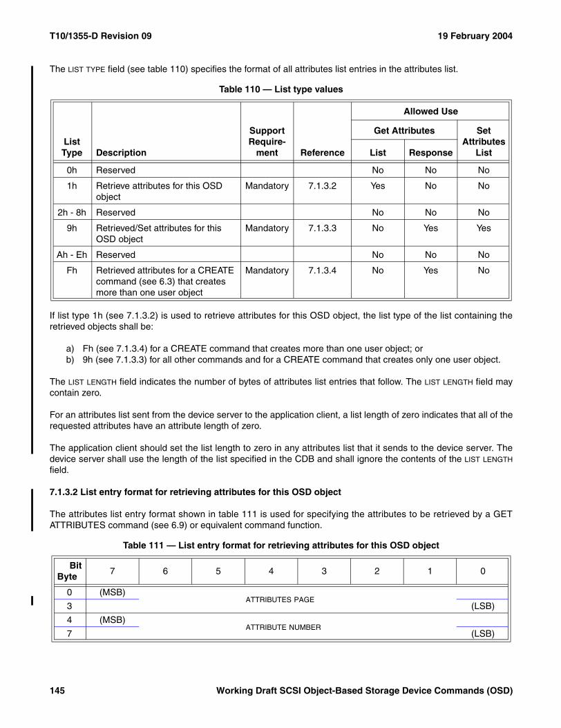
T10/1355-D Revision 09 19 February 2004
The LIST TYPE field (see table 110) specifies the format of all attributes list entries in the attributes list.
If list type 1h (see 7.1.3.2) is used to retrieve attributes for this OSD object, the list type of the list containing theretrieved objects shall be:
a) Fh (see 7.1.3.4) for a CREATE command that creates more than one user object; orb) 9h (see 7.1.3.3) for all other commands and for a CREATE command that creates only one user object.
The LIST LENGTH field indicates the number of bytes of attributes list entries that follow. The LIST LENGTH field maycontain zero.
For an attributes list sent from the device server to the application client, a list length of zero indicates that all of therequested attributes have an attribute length of zero.
The application client should set the list length to zero in any attributes list that it sends to the device server. Thedevice server shall use the length of the list specified in the CDB and shall ignore the contents of the LIST LENGTH
field.
7.1.3.2 List entry format for retrieving attributes for this OSD object
The attributes list entry format shown in table 111 is used for specifying the attributes to be retrieved by a GETATTRIBUTES command (see 6.9) or equivalent command function.
Table 110 — List type values
List Type Description
Support Require-
ment Reference
Allowed Use
Get Attributes Set Attributes
ListList Response
0h Reserved No No No
1h Retrieve attributes for this OSD object
Mandatory 7.1.3.2 Yes No No
2h - 8h Reserved No No No
9h Retrieved/Set attributes for this OSD object
Mandatory 7.1.3.3 No Yes Yes
Ah - Eh Reserved No No No
Fh Retrieved attributes for a CREATE command (see 6.3) that creates more than one user object
Mandatory 7.1.3.4 No Yes No
Table 111 — List entry format for retrieving attributes for this OSD object
BitByte
7 6 5 4 3 2 1 0
0 (MSB)ATTRIBUTES PAGE
3 (LSB)
4 (MSB)ATTRIBUTE NUMBER
7 (LSB)
145 Working Draft SCSI Object-Based Storage Device Commands (OSD)
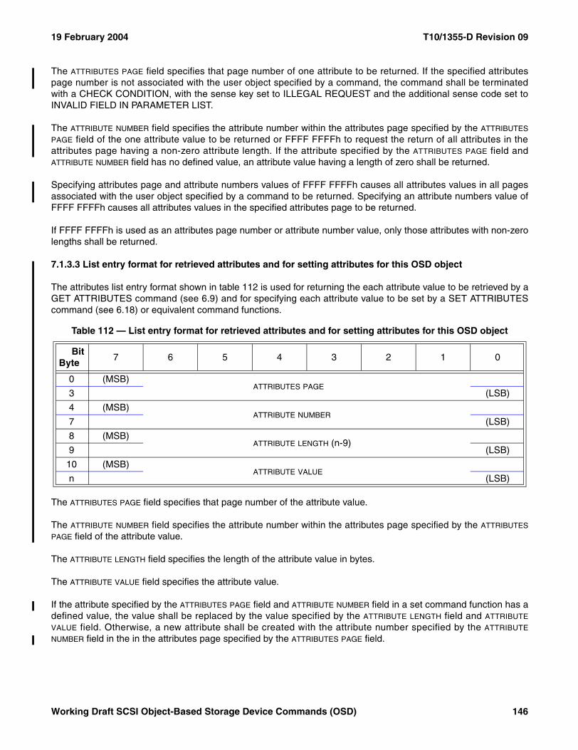
19 February 2004 T10/1355-D Revision 09
The ATTRIBUTES PAGE field specifies that page number of one attribute to be returned. If the specified attributespage number is not associated with the user object specified by a command, the command shall be terminatedwith a CHECK CONDITION, with the sense key set to ILLEGAL REQUEST and the additional sense code set toINVALID FIELD IN PARAMETER LIST.
The ATTRIBUTE NUMBER field specifies the attribute number within the attributes page specified by the ATTRIBUTES
PAGE field of the one attribute value to be returned or FFFF FFFFh to request the return of all attributes in theattributes page having a non-zero attribute length. If the attribute specified by the ATTRIBUTES PAGE field andATTRIBUTE NUMBER field has no defined value, an attribute value having a length of zero shall be returned.
Specifying attributes page and attribute numbers values of FFFF FFFFh causes all attributes values in all pagesassociated with the user object specified by a command to be returned. Specifying an attribute numbers value ofFFFF FFFFh causes all attributes values in the specified attributes page to be returned.
If FFFF FFFFh is used as an attributes page number or attribute number value, only those attributes with non-zerolengths shall be returned.
7.1.3.3 List entry format for retrieved attributes and for setting attributes for this OSD object
The attributes list entry format shown in table 112 is used for returning the each attribute value to be retrieved by aGET ATTRIBUTES command (see 6.9) and for specifying each attribute value to be set by a SET ATTRIBUTEScommand (see 6.18) or equivalent command functions.
The ATTRIBUTES PAGE field specifies that page number of the attribute value.
The ATTRIBUTE NUMBER field specifies the attribute number within the attributes page specified by the ATTRIBUTES
PAGE field of the attribute value.
The ATTRIBUTE LENGTH field specifies the length of the attribute value in bytes.
The ATTRIBUTE VALUE field specifies the attribute value.
If the attribute specified by the ATTRIBUTES PAGE field and ATTRIBUTE NUMBER field in a set command function has adefined value, the value shall be replaced by the value specified by the ATTRIBUTE LENGTH field and ATTRIBUTE
VALUE field. Otherwise, a new attribute shall be created with the attribute number specified by the ATTRIBUTE
NUMBER field in the in the attributes page specified by the ATTRIBUTES PAGE field.
Table 112 — List entry format for retrieved attributes and for setting attributes for this OSD object
BitByte
7 6 5 4 3 2 1 0
0 (MSB)ATTRIBUTES PAGE
3 (LSB)
4 (MSB)ATTRIBUTE NUMBER
7 (LSB)
8 (MSB)ATTRIBUTE LENGTH (n-9)
9 (LSB)
10 (MSB)ATTRIBUTE VALUE
n (LSB)
Working Draft SCSI Object-Based Storage Device Commands (OSD) 146
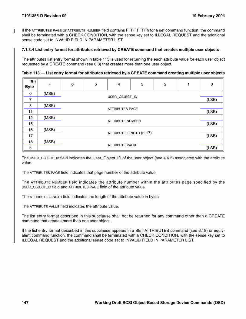
T10/1355-D Revision 09 19 February 2004
If the ATTRIBUTES PAGE or ATTRIBUTE NUMBER field contains FFFF FFFFh for a set command function, the commandshall be terminated with a CHECK CONDITION, with the sense key set to ILLEGAL REQUEST and the additionalsense code set to INVALID FIELD IN PARAMETER LIST.
7.1.3.4 List entry format for attributes retrieved by CREATE command that creates multiple user objects
The attributes list entry format shown in table 113 is used for returning the each attribute value for each user objectrequested by a CREATE command (see 6.3) that creates more than one user object.
The USER_OBJECT_ID field indicates the User_Object_ID of the user object (see 4.6.5) associated with the attributevalue.
The ATTRIBUTES PAGE field indicates that page number of the attribute value.
The ATTRIBUTE NUMBER field indicates the attribute number within the attributes page specified by theUSER_OBJECT_ID field and ATTRIBUTES PAGE field of the attribute value.
The ATTRIBUTE LENGTH field indicates the length of the attribute value in bytes.
The ATTRIBUTE VALUE field indicates the attribute value.
The list entry format described in this subclause shall not be returned for any command other than a CREATEcommand that creates more than one user object.
If the list entry format described in this subclause appears in a SET ATTRIBUTES command (see 6.18) or equiv-alent command function, the command shall be terminated with a CHECK CONDITION, with the sense key set toILLEGAL REQUEST and the additional sense code set to INVALID FIELD IN PARAMETER LIST.
Table 113 — List entry format for attributes retrieved by a CREATE command creating multiple user objects
BitByte
7 6 5 4 3 2 1 0
0 (MSB)USER_OBJECT_ID
7 (LSB)
8 (MSB)ATTRIBUTES PAGE
11 (LSB)
12 (MSB)ATTRIBUTE NUMBER
15 (LSB)
16 (MSB)ATTRIBUTE LENGTH (n-17)
17 (LSB)
18 (MSB)ATTRIBUTE VALUE
n (LSB)
147 Working Draft SCSI Object-Based Storage Device Commands (OSD)
19 February 2004 T10/1355-D Revision 09
7.2 Diagnostic parameters
This subclause defines the descriptors and pages for diagnostic parameters used with OSD type devices.
The diagnostic parameter list is described in SPC-3.
See SPC-3 for diagnostic pages used with all device types.
No diagnostic pages are defined for specific use by OSD type devices.
7.3 Log parameters
This subclause defines the descriptors and pages for log parameters used with OSD type devices.
The log parameter list is described in SPC-3.
See SPC-3 for log parameter pages used with all device types.
No log parameter pages are defined for specific use by OSD type devices.
7.4 Mode parameters
This subclause defines the descriptors and pages for mode parameters used with OSD type devices.
The mode parameter list, including the mode parameter header and mode block descriptor, are described inSPC-3.
OSD type devices shall treat the following mode parameter header fields (see SPC-3) as reserved:
a) MEDIUM TYPE;b) DEVICE-SPECIFIC PARAMETER; andc) LONGLBA.
OSD type devices shall set the BLOCK DESCRIPTOR LENGTH field to zero and shall return a CHECK CONDITIONstatus for any command that attempts to set the block descriptor length to a value other than zero.
See SPC-3 for mode pages used with all device types.
No mode pages are defined for specific use by OSD type devices.
Working Draft SCSI Object-Based Storage Device Commands (OSD) 148
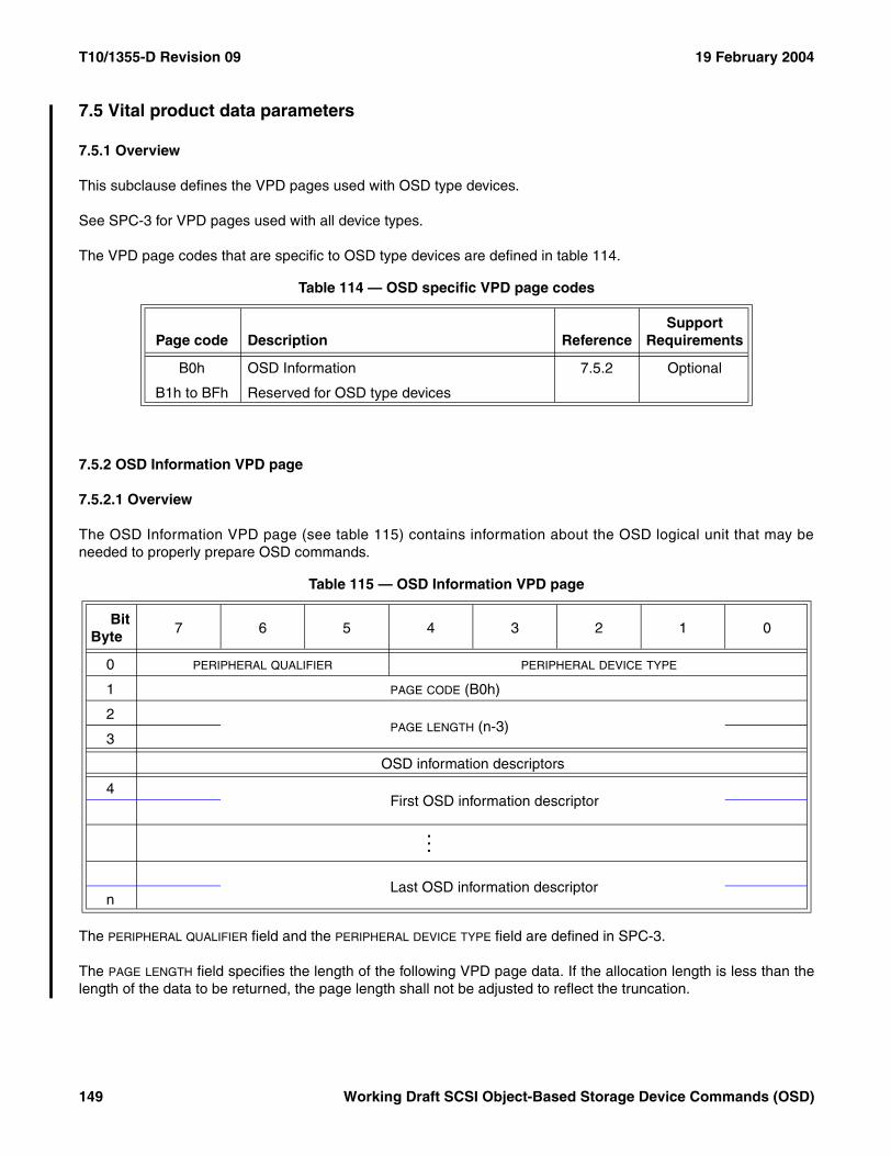
T10/1355-D Revision 09 19 February 2004
7.5 Vital product data parameters
7.5.1 Overview
This subclause defines the VPD pages used with OSD type devices.
See SPC-3 for VPD pages used with all device types.
The VPD page codes that are specific to OSD type devices are defined in table 114.
7.5.2 OSD Information VPD page
7.5.2.1 Overview
The OSD Information VPD page (see table 115) contains information about the OSD logical unit that may beneeded to properly prepare OSD commands.
The PERIPHERAL QUALIFIER field and the PERIPHERAL DEVICE TYPE field are defined in SPC-3.
The PAGE LENGTH field specifies the length of the following VPD page data. If the allocation length is less than thelength of the data to be returned, the page length shall not be adjusted to reflect the truncation.
Table 114 — OSD specific VPD page codes
Page code Description ReferenceSupport
Requirements
B0h OSD Information 7.5.2 Optional
B1h to BFh Reserved for OSD type devices
Table 115 — OSD Information VPD page
BitByte
7 6 5 4 3 2 1 0
0 PERIPHERAL QUALIFIER PERIPHERAL DEVICE TYPE
1 PAGE CODE (B0h)
2PAGE LENGTH (n-3)
3
OSD information descriptors
4First OSD information descriptor
...
Last OSD information descriptorn
149 Working Draft SCSI Object-Based Storage Device Commands (OSD)
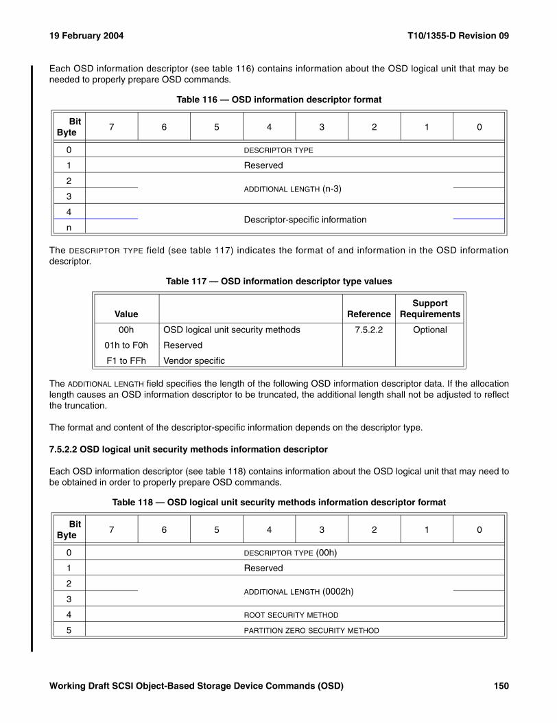
19 February 2004 T10/1355-D Revision 09
Each OSD information descriptor (see table 116) contains information about the OSD logical unit that may beneeded to properly prepare OSD commands.
The DESCRIPTOR TYPE field (see table 117) indicates the format of and information in the OSD informationdescriptor.
The ADDITIONAL LENGTH field specifies the length of the following OSD information descriptor data. If the allocationlength causes an OSD information descriptor to be truncated, the additional length shall not be adjusted to reflectthe truncation.
The format and content of the descriptor-specific information depends on the descriptor type.
7.5.2.2 OSD logical unit security methods information descriptor
Each OSD information descriptor (see table 118) contains information about the OSD logical unit that may need tobe obtained in order to properly prepare OSD commands.
Table 116 — OSD information descriptor format
BitByte
7 6 5 4 3 2 1 0
0 DESCRIPTOR TYPE
1 Reserved
2ADDITIONAL LENGTH (n-3)
3
4Descriptor-specific information
n
Table 117 — OSD information descriptor type values
Value ReferenceSupport
Requirements
00h OSD logical unit security methods 7.5.2.2 Optional
01h to F0h Reserved
F1 to FFh Vendor specific
Table 118 — OSD logical unit security methods information descriptor format
BitByte
7 6 5 4 3 2 1 0
0 DESCRIPTOR TYPE (00h)
1 Reserved
2ADDITIONAL LENGTH (0002h)
3
4 ROOT SECURITY METHOD
5 PARTITION ZERO SECURITY METHOD
Working Draft SCSI Object-Based Storage Device Commands (OSD) 150
T10/1355-D Revision 09 19 February 2004
The DESCRIPTOR TYPE field set to 00h indicates that this is an OSD logical unit security methods informationdescriptor.
The ADDITIONAL LENGTH field specifies the length of the following OSD information descriptor data.
The ROOT SECURITY METHOD field contains the value in the security method attribute in the Root Security attributespage (see 7.1.2.20).
The PARTITION ZERO SECURITY METHOD field contains the value in the security method attribute in the PartitionSecurity attributes page (see 7.1.2.21) associated with partition zero.
151 Working Draft SCSI Object-Based Storage Device Commands (OSD)
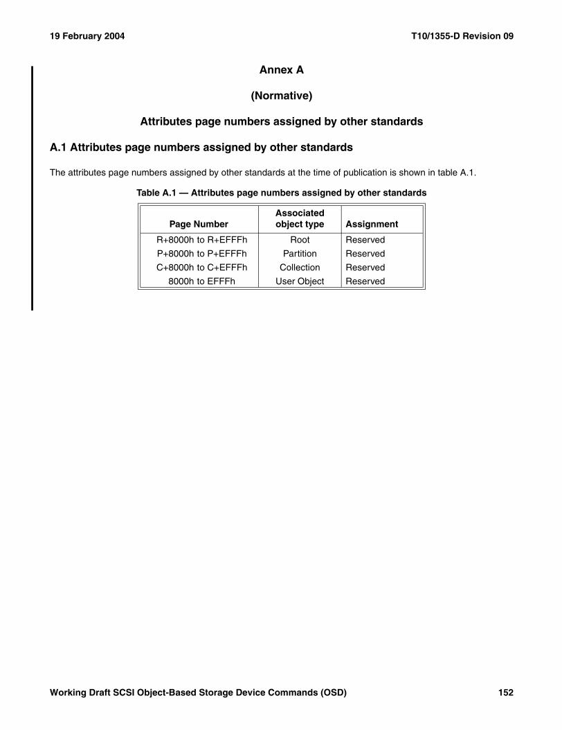
19 February 2004 T10/1355-D Revision 09
Annex A
(Normative)
Attributes page numbers assigned by other standards
A.1 Attributes page numbers assigned by other standards
The attributes page numbers assigned by other standards at the time of publication is shown in table A.1.
Table A.1 — Attributes page numbers assigned by other standards
Page NumberAssociated object type Assignment
R+8000h to R+EFFFh Root Reserved
P+8000h to P+EFFFh Partition Reserved
C+8000h to C+EFFFh Collection Reserved
8000h to EFFFh User Object Reserved
Working Draft SCSI Object-Based Storage Device Commands (OSD) 152
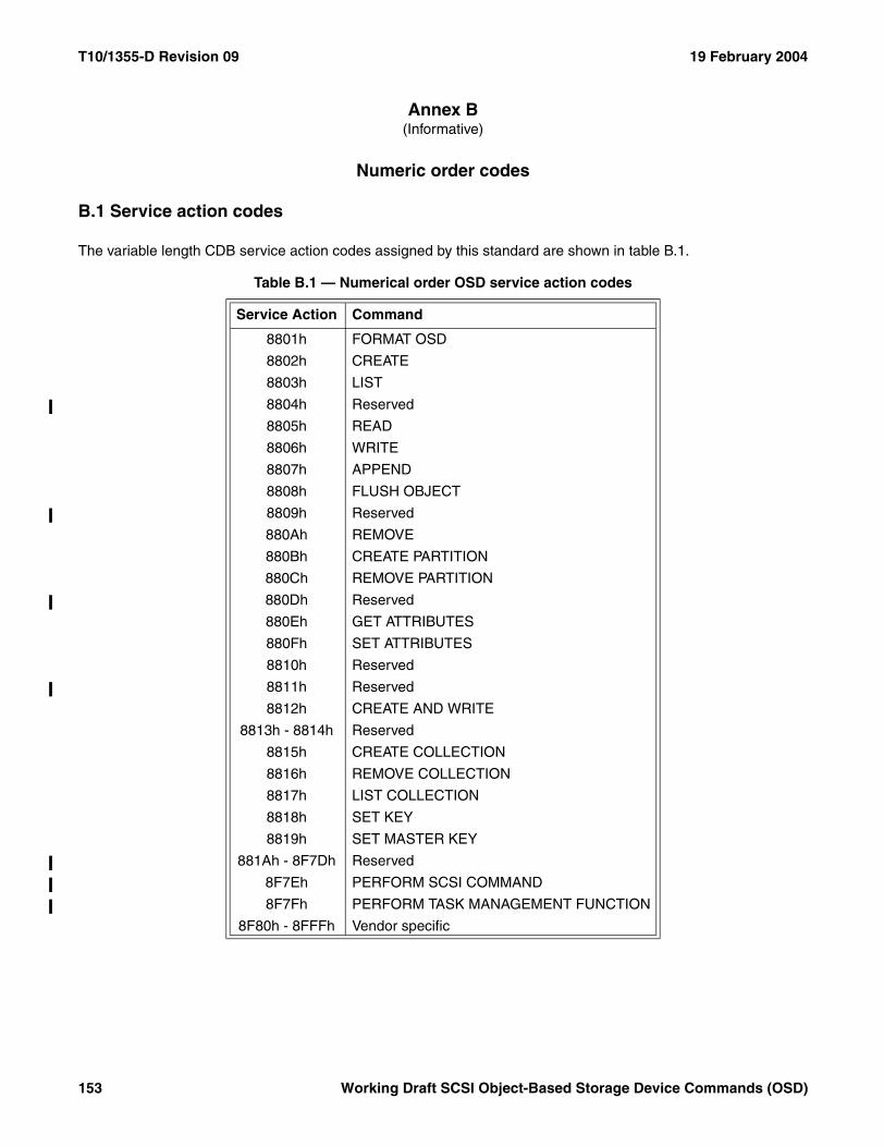
T10/1355-D Revision 09 19 February 2004
Annex B (Informative)
Numeric order codes
B.1 Service action codes
The variable length CDB service action codes assigned by this standard are shown in table B.1.
Table B.1 — Numerical order OSD service action codes
Service Action Command
8801h FORMAT OSD
8802h CREATE
8803h LIST
8804h Reserved
8805h READ
8806h WRITE
8807h APPEND
8808h FLUSH OBJECT
8809h Reserved
880Ah REMOVE
880Bh CREATE PARTITION
880Ch REMOVE PARTITION
880Dh Reserved
880Eh GET ATTRIBUTES
880Fh SET ATTRIBUTES
8810h Reserved
8811h Reserved
8812h CREATE AND WRITE
8813h - 8814h Reserved
8815h CREATE COLLECTION
8816h REMOVE COLLECTION
8817h LIST COLLECTION
8818h SET KEY
8819h SET MASTER KEY
881Ah - 8F7Dh Reserved
8F7Eh PERFORM SCSI COMMAND
8F7Fh PERFORM TASK MANAGEMENT FUNCTION
8F80h - 8FFFh Vendor specific
153 Working Draft SCSI Object-Based Storage Device Commands (OSD)
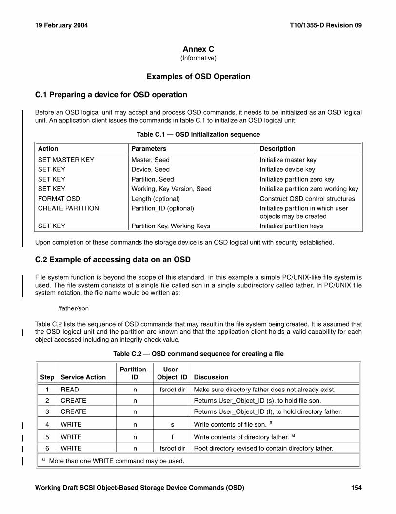
19 February 2004 T10/1355-D Revision 09
Annex C(Informative)
Examples of OSD Operation
C.1 Preparing a device for OSD operation
Before an OSD logical unit may accept and process OSD commands, it needs to be initialized as an OSD logicalunit. An application client issues the commands in table C.1 to initialize an OSD logical unit.
Upon completion of these commands the storage device is an OSD logical unit with security established.
C.2 Example of accessing data on an OSD
File system function is beyond the scope of this standard. In this example a simple PC/UNIX-like file system isused. The file system consists of a single file called son in a single subdirectory called father. In PC/UNIX filesystem notation, the file name would be written as:
/father/son
Table C.2 lists the sequence of OSD commands that may result in the file system being created. It is assumed thatthe OSD logical unit and the partition are known and that the application client holds a valid capability for eachobject accessed including an integrity check value.
Table C.1 — OSD initialization sequence
Action Parameters Description
SET MASTER KEY Master, Seed Initialize master key
SET KEY Device, Seed Initialize device key
SET KEY Partition, Seed Initialize partition zero key
SET KEY Working, Key Version, Seed Initialize partition zero working key
FORMAT OSD Length (optional) Construct OSD control structures
CREATE PARTITION Partition_ID (optional) Initialize partition in which user objects may be created
SET KEY Partition Key, Working Keys Initialize partition keys
Table C.2 — OSD command sequence for creating a file
Step Service ActionPartition_
IDUser_
Object_ID Discussion
1 READ n fsroot dir Make sure directory father does not already exist.
2 CREATE n Returns User_Object_ID (s), to hold file son.
3 CREATE n Returns User_Object_ID (f), to hold directory father.
4 WRITE n s Write contents of file son. a
5 WRITE n f Write contents of directory father. a
6 WRITE n fsroot dir Root directory revised to contain directory father.
a More than one WRITE command may be used.
Working Draft SCSI Object-Based Storage Device Commands (OSD) 154
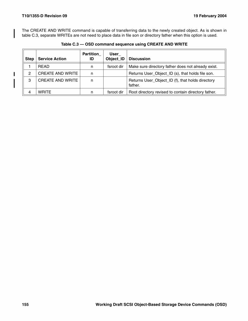
T10/1355-D Revision 09 19 February 2004
The CREATE AND WRITE command is capable of transferring data to the newly created object. As is shown intable C.3, separate WRITEs are not need to place data in file son or directory father when this option is used.
Table C.3 — OSD command sequence using CREATE AND WRITE
Step Service ActionPartition_
IDUser_
Object_ID Discussion
1 READ n fsroot dir Make sure directory father does not already exist.
2 CREATE AND WRITE n Returns User_Object_ID (s), that holds file son.
3 CREATE AND WRITE n Returns User_Object_ID (f), that holds directory father.
4 WRITE n fsroot dir Root directory revised to contain directory father.
155 Working Draft SCSI Object-Based Storage Device Commands (OSD)