Embed Size (px)
Citation preview

IMR01L01-E5
COM-H Instruction Manual
RKC INSTRUMENT INC. ®
DeviceNetCommunication Converter

All Rights Reserved, Copyright © 2001, RKC INSTRUMENT INC.
DeviceNet is a registered trademark of Open DeviceNet Vender Association, Inc.
The name of each programmable controller (PLC) means the products of each manufacturer. Company names and product names used in this manual are the trademarks or registered trademarks of the respective companies. This product has been self-tested by RKC at DeviceNet Protocol Conformance Test Software Version A-17.

IMR01L01-E5 i-1
Thank you for purchasing this RKC product. In order to achieve maximum performance and ensure proper operation of your new instrument, carefully read all the instructions in this manual. Please place the manual in a convenient location for easy reference.
SYMBOLS
: This mark indicates important information on installation, handling and operating procedures.
: This mark indicates supplemental information on installation, handling and operating procedures.
: This mark indicates where additional information may be located.
An external protection device must be installed if failure of this instrument could result in damage to the instrument, equipment or injury to personnel.
All wiring must be completed before power is turned on to prevent electric shock, fire or damage to instrument and equipment.
This instrument must be used in accordance with the specifications to prevent fire or damage to instrument and equipment.
This instrument is not intended for use in locations subject to flammable or explosive gases.
Do not touch high-voltage connections such as power supply terminals, etc. to avoid electric shock.
RKC is not responsible if this instrument is repaired, modified or disassembled by other than factory-approved personnel. Malfunction can occur and warranty is void under these conditions.
CAUTION
: This mark indicates precautions that must be taken if there is danger of electric shock, fire, etc., which could result in loss of life or injury.
: This mark indicates that if these precautions and operating procedures are not
taken, damage to the instrument may result.
: This mark indicates that all precautions should be taken for safe usage.
WARNING
!
WARNING!
IMR01L01-E5 i-2
This product is intended for use with industrial machines, test and measuring equipment. (It is not designed for use with medical equipment and nuclear energy.)
This is a Class A instrument. In a domestic environment, this instrument may cause radio interference, in which case the user may be required to take additional measures.
This instrument is protected from electric shock by reinforced insulation. Provide reinforced insulation between the wire for the input signal and the wires for instrument power supply, source of power and loads.
Be sure to provide an appropriate surge control circuit respectively for the following: - If input/output or signal lines within the building are longer than 30 meters. - If input/output or signal lines leave the building, regardless the length.
This instrument is designed for installation in an enclosed instrumentation panel. All high-voltage connections such as power supply terminals must be enclosed in the instrumentation panel to avoid electric shock by operating personnel.
All precautions described in this manual should be taken to avoid damage to the instrument or equipment.
All wiring must be in accordance with local codes and regulations. All wiring must be completed before power is turned on to prevent electric shock, instrument
failure, or incorrect action. The power must be turned off before repairing work for input break and output failure including replacement of sensor, contactor or SSR, and all wiring must be completed before power is turned on again.
To prevent instrument damage or failure, protect the power line and the input/output lines from high currents with a protection device such as fuse, circuit breaker, etc.
Prevent metal fragments or lead wire scraps from falling inside instrument case to avoid electric shock, fire or malfunction.
Tighten each terminal screw to the specified torque found in the manual to avoid electric shock, fire or malfunction.
For proper operation of this instrument, provide adequate ventilation for heat dispensation. Do not connect wires to unused terminals as this will interfere with proper operation of the
instrument. Turn off the power supply before cleaning the instrument. Do not use a volatile solvent such as paint thinner to clean the instrument. Deformation or
discoloration will occur. Use a soft, dry cloth to remove stains from the instrument. To avoid damage to instrument display, do not rub with an abrasive material or push front
panel with a hard object. Do not connect modular connectors to telephone line. When high alarm with hold action/re-hold action is used for Alarm function, alarm does not turn
on while hold action is in operation. Take measures to prevent overheating which may occur if the control device fails.
NOTICE This manual assumes that the reader has a fundamental knowledge of the principles of electricity,
process control, computer technology and communications. The figures, diagrams and numeric values used in this manual are only for purpose of illustration. RKC is not responsible for any damage or injury that is caused as a result of using this instrument,
instrument failure or indirect damage. RKC is not responsible for any damage and/or injury resulting from the use of instruments made by
imitating this instrument. Periodic maintenance is required for safe and proper operation of this instrument. Some components
have a limited service life, or characteristics that change over time. Every effort has been made to ensure accuracy of all information contained herein. RKC makes no
warranty expressed or implied, with respect to the accuracy of the information. The information in this manual is subject to change without prior notice.
No portion of this document may be reprinted, modified, copied, transmitted, digitized, stored, processed or retrieved through any mechanical, electronic, optical or other means without prior written approval from RKC.
CAUTION

IMR01L01-E5 i-3
CONTENTS
Page 1. OUTLINE.............................................................................. 1
1.1 Product Outline................................................................................................1 1.1.1 Communication ports ........................................................................................... 2 1.1.2 EDS file ................................................................................................................ 3
1.2 Model Code .....................................................................................................4 1.3 Parts Description .............................................................................................5
2. SPECIFICATIONS ................................................................ 8 3. MOUNTING......................................................................... 11
3.1 Mounting Environment...................................................................................11 3.2 Dimensions....................................................................................................12 3.3 Mounting the Mother Block............................................................................13 3.4 Mounting the Module Mainframe ...................................................................15 3.5 Removing the Module Mainframe..................................................................15
4. WIRING ............................................................................... 16
4.1 Wiring Cautions .............................................................................................16 4.2 Terminal Configuration ..................................................................................17 4.3 Connections...................................................................................................18
4.3.1 Connection to DeviceNet ................................................................................... 19 4.3.2 Connection to RKC controllers........................................................................... 22
5. SETTING............................................................................. 40
5.1 DeviceNet Setting..........................................................................................40 5.1.1 Node address setting ......................................................................................... 40 5.1.2 DeviceNet communication speed setting ........................................................... 41
5.2 Connection Controller and Communication Mode Setting .............................42 5.3 Controller Communication Setting .................................................................45

IMR01L01-E5 i-4
Page 6. DeviceNet COMMUNICATIONS ........................................ 47
6.1 Features and Functionality ............................................................................47 6.2 Communication Method.................................................................................48
6.2.1 Controller communication items setting ............................................................. 49 6.2.2 Polling I/O communication ................................................................................. 59 6.2.3 Explicit message communication ....................................................................... 63
6.3 Communication Items List .............................................................................67 6.3.1 SR Mini HG ........................................................................................................ 67 6.3.2 CB100/400/500/700/900 .................................................................................... 72 6.3.3 REX-F400/700/900 ............................................................................................ 73 6.3.4 SA100/200 ......................................................................................................... 76 6.3.5 MA900/901......................................................................................................... 77 6.3.6 LE100................................................................................................................. 79 6.3.7 REX-PG410 ....................................................................................................... 82
7. USAGE EXAMPLE ............................................................. 83
7.1 Handling Procedures .....................................................................................83 7.2 System Configuration ....................................................................................84 7.3 Hardware Setting...........................................................................................85 7.4 Communication Items setting ........................................................................86 7.5 Sample Programs..........................................................................................88
7.5.1 Polling I/O communication (When the SYSMAC CS1) ...................................... 88 7.5.2 Polling I/O communication (When the Control Logix 5550) ............................... 92 7.5.3 Explicit message communication ....................................................................... 99
8. TROUBLESHOOTING...................................................... 104 APPENDIX ............................................................................ 107
A. Device Profiles ..............................................................................................107 A.1 Basic data ........................................................................................................... 107 A.2 Object mounting.................................................................................................. 108
B. Signal Description and Wiring Diagram of COM.PORT1 ..............................118
B.1 RS-232C............................................................................................................. 118 B.2 RS-422A ............................................................................................................. 120
IMR01L01-E5 1
1. OUTLINE
This manual describes the specifications, mounting, wiring and setting of switch and data instructions for the COM-H.
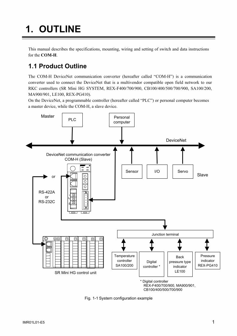
1.1 Product Outline The COM-H DeviceNet communication converter (hereafter called “COM-H”) is a communication converter used to connect the DeviceNet that is a multivendor compatible open field network to our RKC controllers (SR Mini HG SYSTEM, REX-F400/700/900, CB100/400/500/700/900, SA100/200, MA900/901, LE100, REX-PG410). On the DeviceNet, a programmable controller (hereafter called “PLC”) or personal computer becomes a master device, while the COM-H, a slave device.
Fig. 1-1 System configuration example
RS-422A or
RS-232C
DeviceNet communication converter COM-H (Slave)
PLC
I/O Sensor
DeviceNet
Master
Slave
SR Mini HG control unit
Servo
Personal computer
Junction terminal
or
Temperature controller
SA100/200
* Digital controller REX-F400/700/900, MA900/901, CB100/400/500/700/900
Pressure indicator
REX-PG410Digital
controller *
Back pressure type
indicator LE100
1. OUTLINE
IMR01L01-E5 2
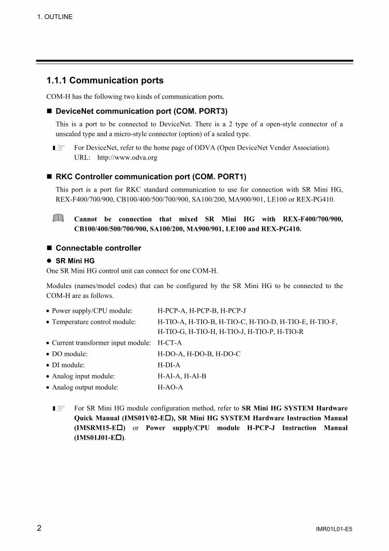
1.1.1 Communication ports COM-H has the following two kinds of communication ports. DeviceNet communication port (COM. PORT3) This is a port to be connected to DeviceNet. There is a 2 type of a open-style connector of a unsealed type and a micro-style connector (option) of a sealed type.
For DeviceNet, refer to the home page of ODVA (Open DeviceNet Vender Association). URL: http://www.odva.org
RKC Controller communication port (COM. PORT1) This port is a port for RKC standard communication to use for connection with SR Mini HG, REX-F400/700/900, CB100/400/500/700/900, SA100/200, MA900/901, LE100 or REX-PG410.
Cannot be connection that mixed SR Mini HG with REX-F400/700/900, CB100/400/500/700/900, SA100/200, MA900/901, LE100 and REX-PG410.
Connectable controller SR Mini HG
One SR Mini HG control unit can connect for one COM-H. Modules (names/model codes) that can be configured by the SR Mini HG to be connected to the COM-H are as follows. • Power supply/CPU module: H-PCP-A, H-PCP-B, H-PCP-J • Temperature control module: H-TIO-A, H-TIO-B, H-TIO-C, H-TIO-D, H-TIO-E, H-TIO-F,
H-TIO-G, H-TIO-H, H-TIO-J, H-TIO-P, H-TIO-R • Current transformer input module: H-CT-A • DO module: H-DO-A, H-DO-B, H-DO-C • DI module: H-DI-A • Analog input module: H-AI-A, H-AI-B • Analog output module: H-AO-A
For SR Mini HG module configuration method, refer to SR Mini HG SYSTEM Hardware Quick Manual (IMS01V02-E ), SR Mini HG SYSTEM Hardware Instruction Manual (IMSRM15-E ) or Power supply/CPU module H-PCP-J Instruction Manual (IMS01J01-E ).
1. OUTLINE
IMR01L01-E5 3
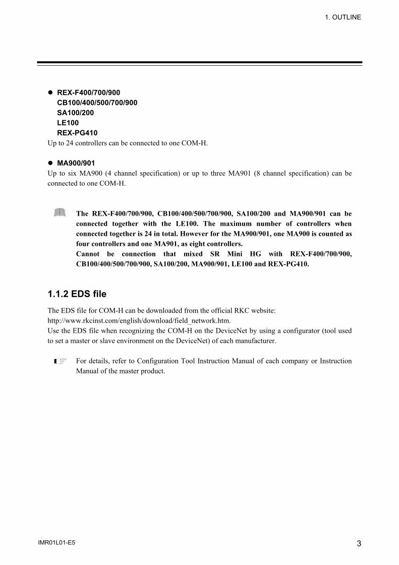
REX-F400/700/900 CB100/400/500/700/900 SA100/200 LE100 REX-PG410
Up to 24 controllers can be connected to one COM-H. MA900/901
Up to six MA900 (4 channel specification) or up to three MA901 (8 channel specification) can be connected to one COM-H.
The REX-F400/700/900, CB100/400/500/700/900, SA100/200 and MA900/901 can be connected together with the LE100. The maximum number of controllers when connected together is 24 in total. However for the MA900/901, one MA900 is counted as four controllers and one MA901, as eight controllers. Cannot be connection that mixed SR Mini HG with REX-F400/700/900, CB100/400/500/700/900, SA100/200, MA900/901, LE100 and REX-PG410.
1.1.2 EDS file The EDS file for COM-H can be downloaded from the official RKC website: http://www.rkcinst.com/english/download/field_network.htm. Use the EDS file when recognizing the COM-H on the DeviceNet by using a configurator (tool used to set a master or slave environment on the DeviceNet) of each manufacturer.
For details, refer to Configuration Tool Instruction Manual of each company or Instruction Manual of the master product.

1. OUTLINE
IMR01L01-E5 4
1.2 Model Code The model code for the instrument you received is listed below. Please confirm that you have received the correct instrument by checking the nameplate, located on the left side of the COM-H, with this list. If the product you received is not the one ordered, contact RKC sales office or agent for replacement. DeviceNet communication converter COM - H - 3 - 90 - -
(1) (2) (3) (4) (1) Power supply type
3: 24 V DC (2) Corresponding RKC controller
90: SR Mini HG SYSTEM REX-F400/700/900 CB100/400/500/700/900 SA100/200 MA900/901 LE100 REX-PG410
(3) Controller communication *
1: RS-232C (RKC communication) 4: RS-422A (RKC communication)
* It is required to coincide with the communication interface for the corresponding RKC controller. When uses the controllers of RS-485 interface, wires it with TA-RA and TB-RB with the communication terminal of the controller.
(4) Connector types
N: Open-style connector (Unshielded type) 1: Micro-style connector (Shield type)
Modular connector cables (Sold separately) W - BF - 01 - W-BF-01: Used to connect the REX-F400/700/900, CB100/400/500/700/900, SA100/200, MA900/901, LE100 or REX-PG410.
W - BF - 02 -
W-BF-02: Used to connect the SR Mini HG.
“ ” are filled with cable length in mm. Please specify the length on your purchasing order. The standard length is “3000.”
1. OUTLINE
IMR01L01-E5 5
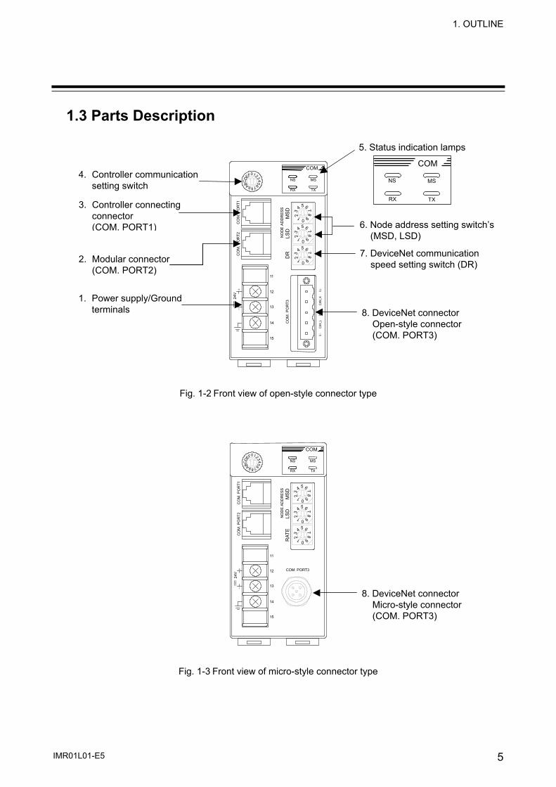
1.3 Parts Description
876
543210FEDC B A9
54
32 1 09
876
54
32 1 09
876
54
32 1 09
876
NS MS
RX TX
CO
M. P
OR
T1
CO
M. P
OR
T2
CO
M. P
OR
T3 24
V +
−
NO
DE
ADD
RES
S M
SD
LSD
D
R
V +
CAN_
H Dr
ain
CAN_
L V −
11
12
13
14
15
COM
Fig. 1-2 Front view of open-style connector type
876
543210FEDC B A9
54
32 1 09
876
54
32 1 09
876
54
32 1 09
876
NS MS
RX TX
CO
M. P
OR
T1
CO
M. P
OR
T2
COM. PORT3
24V
+ −
NO
DE
AD
DR
ESS
M
SD
LSD
R
ATE
11
12
13
14
15
COM
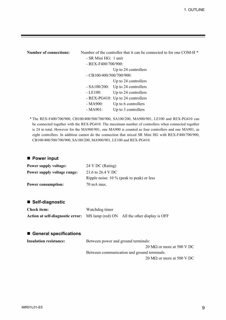
Fig. 1-3 Front view of micro-style connector type
4. Controller communication setting switch
3. Controller connecting connector (COM. PORT1)
1. Power supply/Ground terminals
2. Modular connector (COM. PORT2)
5. Status indication lamps
6. Node address setting switch’s (MSD, LSD)
8. DeviceNet connector Open-style connector (COM. PORT3)
7. DeviceNet communication speed setting switch (DR)
NS MS
COM
RX TX
8. DeviceNet connector Micro-style connector (COM. PORT3)

1. OUTLINE
IMR01L01-E5 6
Fig. 1-4 Side view No. Name Description
1 Power supply/Ground terminals
Power supply terminals and Ground terminal
2 Modular connector (COM. PORT2)
Unused
3 Controller connecting connector (COM. PORT1)
Controller communication port (RS-422A or RS-232C)
4 Controller communication setting switch
Controller communication speed and data bit configuration setting switch
5 Status indication lamps NS (Network Status) • OFF:
Power supply OFF or DeviceNet is off line • Flashing (Green):
Network is operating normally, but communications have not yet been established
• ON (Green): Network is operating normally (communications established)
• Flashing (Red): Connection of one or more is timeout
• ON (Red): A fatal communications error has occurred Network communications are not possible Check for a node address duplication or Bus Off error
Continued on the next page.
9. Mother block
Mainframe

1. OUTLINE
IMR01L01-E5 7
Continued from the previous page. No. Name Description
5 Status indication lamps MS (Module Status) • OFF:
Power is not spplied • Flashing (Green):
In activation, be checking communication with controller • ON (Green):
Normal operating status • ON (Red):
Watchdog timer error RX (Yellow) ON during the controller data is correctly received TX (Yellow) ON during the controller data is correctly sent
6 Node address setting switch’s (MSD, LSD)
Set node address (MAC ID) number of the DeviceNet Setting range: 00 to 63 Upper-side (MSD): High-order digit setting (Set value × 10) Lower-side (LSD): Low-order digit setting (Set value × 1)
7 DeviceNet communication speed setting switch (DR or RATE)
DeviceNet communication speed setting switch
8 DeviceNet connector (COM. PORT3)
The communication port for DeviceNet connection
9 Mother block Module DIN rail mounting connector

8 IMR01L01-E5
2. SPECIFICATIONS
DeviceNet communication Protocol: DeviceNet Supported connection: Polling I/O, Explicit message Connection method: Multi-drop connection, T-branch connection
(Terminating resistor is necessary) Communication speed: 125 kbps, 250 kbps, 500 kbps
(Communication speed can be selected with switch) Factory set value: 125 kbps
Communication length:
* The maximum of length between nodes
Maximum number of connection nodes: 64 (including master) Error control: CRC error, Node address (MAC ID) duplication check Controller communication
Communication interface: Based on RS-422A, EIA standard Based on RS-232C, EIA standard Specify when ordering
Communication method: Four-wire system, half-duplex multi-drop connection (RS-422A) Half-duplex point-to-point connection (RS-232C)
Protocol: RKC communication (Based on ANSI X 3.28 subcategories 2.5 and B1)
Synchronous method: Start/stop synchronous type Communication speed: 4800 bps, 9600 bps, 19200 bps
(Communication speed can be selected with switch) Factory set value: 9600 bps
Data bit configuration: Start bit: 1 Data bit: 7 or 8 Parity bit: Without, Odd or Even Without for 8 data bits Stop bit: 1 Communication code: ASCII 7-bit code
Communication Maximum network length * Maximum Cumulative
speed Thick trunk length Thin trunk length drop length drop length
125 kbps 500 m or less 156 m or less250 kbps 250 m or less 100 m or less 6 m or less 78 m or less500 kbps 100 m or less 39 m or less
1. OUTLINE
IMR01L01-E5 9
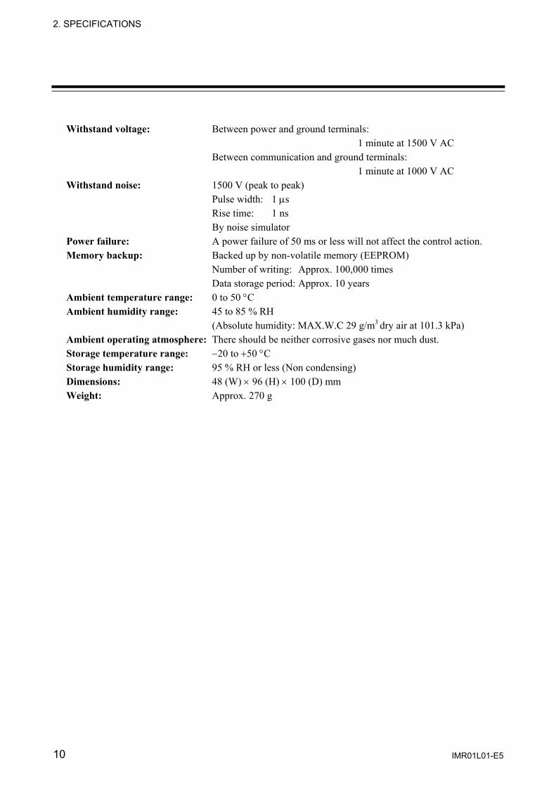
Number of connections: Number of the controller that it can be connected to for one COM-H *
- SR Mini HG: 1 unit - REX-F400/700/900: Up to 24 controllers - CB100/400/500/700/900: Up to 24 controllers - SA100/200: Up to 24 controllers - LE100: Up to 24 controllers - REX-PG410: Up to 24 controllers - MA900: Up to 6 controllers - MA901: Up to 3 controllers
* The REX-F400/700/900, CB100/400/500/700/900, SA100/200, MA900/901, LE100 and REX-PG410 can
be connected together with the REX-PG410. The maximum number of controllers when connected together is 24 in total. However for the MA900/901, one MA900 is counted as four controllers and one MA901, as eight controllers. In addition cannot do the connection that mixed SR Mini HG with REX-F400/700/900, CB100/400/500/700/900, SA100/200, MA900/901, LE100 and REX-PG410.
Power input
Power supply voltage: 24 V DC (Rating) Power supply voltage range: 21.6 to 26.4 V DC
Ripple noise: 10 % (peak to peak) or less Power consumption: 70 mA max. Self-diagnostic
Check item: Watchdog timer Action at self-diagnostic error: MS lamp (red) ON All the other display is OFF General specifications
Insulation resistance: Between power and ground terminals: 20 MΩ or more at 500 V DC Between communication and ground terminals: 20 MΩ or more at 500 V DC
2. SPECIFICATIONS
IMR01L01-E5 10
Withstand voltage: Between power and ground terminals: 1 minute at 1500 V AC Between communication and ground terminals: 1 minute at 1000 V AC Withstand noise: 1500 V (peak to peak) Pulse width: 1 μs Rise time: 1 ns By noise simulator Power failure: A power failure of 50 ms or less will not affect the control action. Memory backup: Backed up by non-volatile memory (EEPROM) Number of writing: Approx. 100,000 times Data storage period: Approx. 10 years Ambient temperature range: 0 to 50 °C Ambient humidity range: 45 to 85 % RH (Absolute humidity: MAX.W.C 29 g/m3 dry air at 101.3 kPa) Ambient operating atmosphere: There should be neither corrosive gases nor much dust. Storage temperature range: −20 to +50 °C Storage humidity range: 95 % RH or less (Non condensing) Dimensions: 48 (W) × 96 (H) × 100 (D) mm Weight: Approx. 270 g
IMR01L01-E5 11
3. MOUNTING
3.1 Mounting Environment (1) This instrument is intended to be used under the following environmental conditions. (IEC61010-1)
[OVERVOLTAGE CATEGORY II, POLLUTION DEGREE 2]
(2) Use this instrument within the following environment conditions: • Allowable ambient temperature: 0 to 50 °C • Allowable ambient humidity: 45 to 85 % RH
(Absolute humidity: MAX.W.C 29 g/m3 dry air at 101.3 kPa) • Installation environment conditions: Indoor use
Altitude up to 2000 m
(3) Avoid the following conditions when selecting the mounting location: • Rapid changes in ambient temperature which may cause condensation. • Corrosive or inflammable gases. • Direct vibration or shock to the mainframe. • Water, oil, chemicals, vapor or steam splashes. • Excessive dust, salt or iron particles. • Excessive induction noise, static electricity, magnetic fields or noise. • Direct air flow from an air conditioner. • Exposure to direct sunlight. • Excessive heat accumulation.
(4) Mount this instrument in the panel considering the following conditions: • Ensure at least 50 mm space on top and bottom of the instrument for maintenance and
environmental reasons. • Do not mount this instrument directly above equipment that generates large amount of heat
(heaters, transformers, semi-conductor functional devices, large-wattage resistors). • If the ambient temperature rises above 50 °C, cool this instrument with a forced air fan, cooler,
etc. Cooled air should not blow directly on this instrument. • In order to improve safety and the immunity to withstand noise, mount this instrument as far
away as possible from high voltage equipment, power lines, and rotating machinery. High voltage equipment: Do not mount within the same panel. Power lines: Separate at least 200 mm. Rotating machinery: Separate as far as possible.
(5) If this instrument is permanently connected to equipment, it is important to include a switch or circuit-breaker into the installation. This should be in close proximity to the equipment and within easy reach of the operator. It should be marked as the disconnecting device for the equipment.
To prevent electric shock or instrument failure, always turn off the power before mounting or removing the instrument.
WARNING!
3. MOUNTING
IMR01L01-E5 12
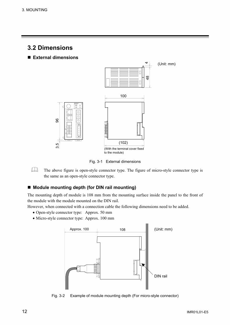
3.2 Dimensions External dimensions
4 48
96
3.5 (102)
(Unit: mm)
100
(With the terminal cover fixed to the module)
Fig. 3-1 External dimensions
The above figure is open-style connector type. The figure of micro-style connector type is the same as an open-style connector type.
Module mounting depth (for DIN rail mounting)
The mounting depth of module is 108 mm from the mounting surface inside the panel to the front of the module with the module mounted on the DIN rail. However, when connected with a connection cable the following dimensions need to be added.
• Open-style connector type: Approx. 50 mm • Micro-style connector type: Approx. 100 mm
108Approx. 100
Fig. 3-2 Example of module mounting depth (For micro-style connector)
(Unit: mm)
DIN rail

3. MOUNTING
IMR01L01-E5 13
3.3 Mounting the Mother Block The mother block can be mounted to a panel or DIN rail. Panel mounting 1. Refer to both the panel mounting dimensions below and the external dimensions in previous
section when selecting the location.
2477
4-M3 (Unit: mm)
Fig. 3-3 Mounting dimensions
2. Remove the module from the mother block. For details of removing the module, refer to 3.5 Removing the Module Mainframe (P. 15).
3. Connect the mother blocks together before tightening the screws on the panel.
(Customer must provide the set screws)
M3×10
Mother block
Fig. 3-4 Panel mounting
Recommended tightening torque : 0.3 N⋅m (3 kgf⋅cm)
When the mother block is mounted on the panel, 50 mm or more space is required at the top and bottom of the mother block to attach the module mainframe.

3. MOUNTING
IMR01L01-E5 14
DIN rail mounting
1. Remove the module mainframe from the mother block. For details of removing the module mainframe, refer to 3.5 Removing the Module Mainframe (P. 15).
2. Pull down both locking devices at the bottom of the mother block. (A)
3. Attach the top bracket of the mother block to the DIN rail and push the lower section into place on the DIN rail. (B)
4. Slide the locking devices up to secure the mother block to the DIN rail. (C)
Locking device (C)(B)
(A)
Mother block
Push
DIN rail
Locked
Pull down
Fig. 3-5 Mounting the mother block
When the mother block is mounted on panel, 50 mm or more space is required at the top and bottom of the mother block to attach the module mainframe.

3. MOUNTING
IMR01L01-E5 15
3.4 Mounting the Module Mainframe 1. Place the module mainframe opening on top of the mother block tab. (A)
2. Snap the lower part of module mainframe on to the mother block. (B)
A
B Opening at top of module
Tab at top of mother block
Fig. 4-6 Module mounting
A snapping sound will be heard when module mainframe is securely connected to mother block.
3.5 Removing the Module Mainframe To separate the module mainframe from the mother block, press the bottom on the module, lifting upward, to release connection.
Fig. 4-7 Removing the Module
Press bottom of module and lift upward to release
Mother block Module mainframe
Upper section
Mother block
Module mainframe
Lower section

16 IMR01L01-E5
4. WIRING
4.1 Wiring Cautions • To avoid noise induction, keep communication signal wires away from instrument power line, load
lines and power lines of other electric equipment. • If there is electrical noise in the vicinity of the instrument that could affect operation, use a noise
filter. − Shorten the distance between the twisted power supply wire pitches to achieve the most effective
noise reduction. − Always install the noise filter on a grounded panel. Minimize the wiring distance between the
noise filter output and the instrument power supply terminals to achieve the most effective noise reduction.
− Do not connect fuses or switches to the noise filter output wiring as this will reduce the effectiveness of the noise filter.
• Power supply wiring must be twisted and have a low voltage drop. • For an instrument with 24 V power supply, supply power from a SELV circuit. • A suitable power supply should be considered in end-use equipment. The power supply must be in
compliance with a limited-energy circuits (maximum available current of 8 A). • Ground the instrument separately from other equipment. The grounding resistance should be 100 Ω
or less. Use grounding wires with a cross section area of 2.0 mm2 or more. • Use the specified solderless terminals. Only these specified solderless terminals can be used due to the
insulation between the terminals. Screw Size: M3 × 7 Recommended tightening torque: 0.4 N・m (4 kgf・cm) Applicable wire: Solid/Twisted wire of 0.25 to 1.65 mm2 Specified solderless terminals: Manufactured by J.S.T MFG CO., LTD. Circular terminal with isolation V1.25−MS3 (M3 screw, width 5.5 mm, hole diameter 3.2 mm)
• Make sure that the any wiring such as solderless terminal is not in contact with the adjoining terminals.
To prevent electric shock or instrument failure, do not turn on the power until all wiring is completed. Make sure that the wiring is correct before applying power to the instrument.
WARNING!
φ 5.5 MAX
φ 3.2 MIN
4 mm
9.0 mm
φ 3.2

4. WIRING
IMR01L01-E5 17
4.2 Terminal Configuration
Power terminal
24 V
DC +
− 13121314Ground terminal
14
Terminal screws Screw size: M3 Recommended tightening torque: 0.4 N m (4 kgf⋅cm)
12
Fig. 4-1 Power supply/ground wiring
The above figure is open-style connector type. The figure of micro-style connector type is the same as a open-style connector type.
Power supply 21.6 to 26.4 V DC Including power supply voltage variations (Rating: 24 V DC)
Ground Ground the instrument separately from other equipment. The grounding resistance should be 100 Ω or less. Use grounding wires with a cross section area of 2.0 mm2 or more.

4. WIRING
IMR01L01-E5 18
4.3 Connections
Connect connectors correctly in the right position. If it is forcibly pushed in with pins in the wrong positions, the pins may be bent resulting in instrument failure. When connecting or disconnecting the connectors, do not force it too far to right and left or up and down, but move it on the straight. Otherwise, the connector pins may be bent, causing instrument failure. When disconnecting a connector, hold it by the connector itself. Disconnecting connectors by yanking on their cables can cause breakdowns. To prevent malfunction, never touch the contact section of a connector with bare hands or with hands soiled with oil or the like. To prevent malfunction, connect cable connectors securely, then firmly tighten the connector fastening screws. To prevent damage to cables, do not bend cables over with excessive force.
CAUTION
To prevent electric shock or instrument failure, turn off the power before connecting or disconnecting the instrument and peripheral equipment.
WARNING!

3. WIRING
IMR01L01-E5 19
4.3.1 Connection to DeviceNet Open-style connector Pin layout of COM.PORT3
Fig. 4-2 Pin layout of COM.PORT3 (open-style connector) Connector pin number and signal details
Pin No. Signal Name Symbol Cable color1 Power supply minus (−) V− Black 2 Communication data low CAN_L Blue 3 Shield Drain ⎯ 4 Communication data high CAN_H White 5 Power supply plus (+) V+ Red
Connection plugs (recommended models)
• Standard type MSTB2.5/5-STF-5.08AU M: PHOENIX CONTACT, Inc. • Multi-drop type TMSTBP2.5/5-STF-5.08AU M: PHOENIX CONTACT, Inc.
COM-H-3-90- -N
DeviceNet connector Open-style connector
(COM. PORT3)
5: V+ 4: CAN_H 3: Drain 2: CAN_L 1: V−

4. WIRING
IMR01L01-E5 20
Micro-style connector Pin layout of COM.PORT3
Fig. 4-3 Pin layout of COM.PORT3 (micro-style connector) Connector pin number and signal details
Pin No. Signal Name Symbol Cable color1 Shield Drain ⎯ 2 Power supply plus (+) V+ Red 3 Power supply minus (−) V− Black 4 Communication data high CAN_H White 5 Communication data low CAN_L Blue
Connection socket (recommended model)
SACC-M12FS-5CON-PG 9-M: PHOENIX CONTACT, Inc.
This socket is a type to use thin cable. Cable
Use the communication cable (thick cable or thin cable) that matched specification of DeviceNet.
By thickness of a cable to use and connection method, usable connection connector type is different.
For cable specifications, connection method and vendor, refer to the home page of ODVA (Open DeviceNet Vender Association). URL: http://www.odva.org
COM-H-3-90- -1
DeviceNet connector Micro-style connector
(COM. PORT3)
5: CAN_L
4: CAN_H
3: V− 2: V+
1: Drain

3. WIRING
IMR01L01-E5 21
Connection outline of DeviceNet The following diagram shows the configuration of a DeviceNet network.
Fig. 4-4 Network configuration example • Nodes
There are two kinds of nodes of master and slave in DeviceNet. The master and slaves can be connected at any location in the network.
• Trunk/Drop lines The trunk line refers to the cable that has Terminating Resistors on both ends. Cables branching from the trunk line are known as drop lines. Use the DeviceNet communication cable (thick or thin cable) for Trunk/Drop lines.
• Connection methods Two methods can be used to connect DeviceNet nodes: The T-branch method and the multi-drop method. With the T-branch method, the node is connected to a drop line created with a T-branch Tap. With the multi-drop method, the node is directly connected to the trunk line or the drop line.
• Terminating resistors In DeviceNet a terminating resistor must be connected to each end of the trunk line Specification of terminating resistor: 121 Ω, ±1 %, 1/4 W (Metal film resistance)
• Communications power supplies To use DeviceNet, connect a communications power supply (24 V DC) to the communications connector of each node with a cable.
For network laying requirement of DeviceNet/method, refer to Instruction Manual of master product or DeviceNet specifications. DeviceNet specifications are available from ODVA (Open DeviceNet Vender Association). URL: http://www.odva.org
Communicationpower
Power supply tap
T-branchtap
T-branchtap
Trunk line
Trunk line
Trunk line
Trunk line
Trunk line
Terminating resistor
Terminating resistor Node
Drop line
Drop line
Drop line
Node
Node Node
4. WIRING
IMR01L01-E5 22
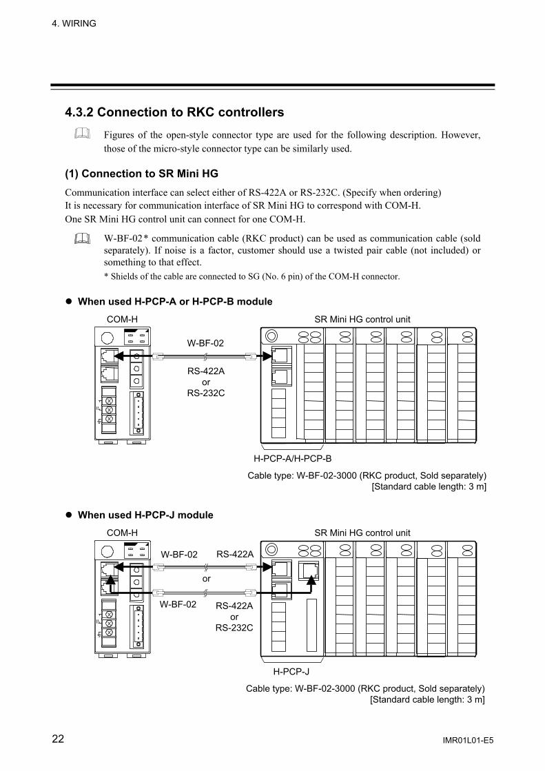
4.3.2 Connection to RKC controllers Figures of the open-style connector type are used for the following description. However, those of the micro-style connector type can be similarly used.
(1) Connection to SR Mini HG Communication interface can select either of RS-422A or RS-232C. (Specify when ordering) It is necessary for communication interface of SR Mini HG to correspond with COM-H. One SR Mini HG control unit can connect for one COM-H.
W-BF-02* communication cable (RKC product) can be used as communication cable (sold separately). If noise is a factor, customer should use a twisted pair cable (not included) or something to that effect. * Shields of the cable are connected to SG (No. 6 pin) of the COM-H connector.
When used H-PCP-A or H-PCP-B module
When used H-PCP-J module
COM-H SR Mini HG control unit
W-BF-02
RS-422A or
RS-232C
RS-422A
RS-422Aor
RS-232C
H-PCP-A/H-PCP-B
COM-H SR Mini HG control unit
W-BF-02
W-BF-02
or
H-PCP-J
Cable type: W-BF-02-3000 (RKC product, Sold separately)[Standard cable length: 3 m]
Cable type: W-BF-02-3000 (RKC product, Sold separately)[Standard cable length: 3 m]
3. WIRING
IMR01L01-E5 23
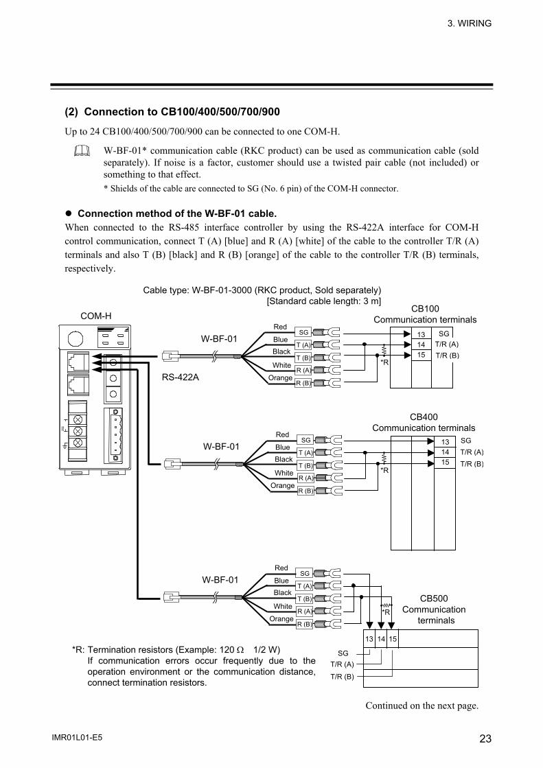
(2) Connection to CB100/400/500/700/900
Up to 24 CB100/400/500/700/900 can be connected to one COM-H.
W-BF-01* communication cable (RKC product) can be used as communication cable (sold separately). If noise is a factor, customer should use a twisted pair cable (not included) or something to that effect. * Shields of the cable are connected to SG (No. 6 pin) of the COM-H connector.
Connection method of the W-BF-01 cable.
When connected to the RS-485 interface controller by using the RS-422A interface for COM-H control communication, connect T (A) [blue] and R (A) [white] of the cable to the controller T/R (A) terminals and also T (B) [black] and R (B) [orange] of the cable to the controller T/R (B) terminals, respectively.
Continued on the next page.
COM-H CB100
Communication terminals13 14 15
SGT/R (A)T/R (B)
SGT/R (A)
T/R (B)
SG
T/R (B)T/R (A)
131415
13 14 15
Cable type: W-BF-01-3000 (RKC product, Sold separately) [Standard cable length: 3 m]
CB400 Communication terminals
CB500 Communication
terminals
RS-422A
W-BF-01
White
BlackBlue
Red
Orange
T (A)
SG
T (B)
R (A)
R (B)
W-BF-01
White
BlackBlue
Red
Orange
T (A)
SG
T (B)
R (A)
R (B)
W-BF-01
White
BlackBlue
Red
Orange
T (A)
SG
T (B)
R (A)
R (B)
*R
*R
*R
*R: Termination resistors (Example: 120 Ω 1/2 W) If communication errors occur frequently due to theoperation environment or the communication distance,connect termination resistors.

4. WIRING
IMR01L01-E5 24
Junction terminals
Up to 24 controllers
Continued from the previous page. Multi-drop connecting example
13 14 15
SG
T/R (B)T/R (A)
13 14 15
SG
T/R (B)T/R (A)
COM-H
Cable type: W-BF-01-3000 (RKC product, Sold separately)[Standard cable length: 3 m]
RS-422A
W-BF-01
White
BlackBlue
Red
Orange
T (A)
SG
T (B)
R (A)
R (B)
7 8 9
SG
T/R (B) T/R (A)
CB700 Communication terminals
T/R (A)T/R (B)
COM-H
RS-422A
W-BF-01
White
BlackBlue
Red
Orange
T (A)
SG
T (B)
R (A)
R (B)
CB100 Communication terminals
CB100 Communication terminals
*R
*R
W-BF-01
White
BlackBlue
Red
Orange
T (A)
SG
T (B)
R (A)
R (B)
SG131415
CB900 Communication terminals
*R
*R: Termination resistors (Example: 120 Ω 1/2 W) If communication errors occur frequently due to theoperation environment or the communication distance,connect termination resistors.
*R: Termination resistors (Example: 120 Ω 1/2 W) If communication errors occur frequently due to theoperation environment or the communication distance,connect termination resistors.

4. WIRING
IMR01L01-E5 25
(3) Connection to REX-F400/700/900
RS-232C One REX-F400/700/900 can be connected to one COM-H.
W-BF-01* communication cable (RKC product) can be used as communication cable (sold separately). If noise is a factor, customer should use a twisted pair cable (not included) or something to that effect. * Shields of the cable are connected to SG (No. 6 pin) of the COM-H connector.
Be sure to insulate the wires that are not used by covering them with insulating tape.
RS-232C
RDSD
Unused
Unused
COM-H
SG121314
161718
262728
SGSDRD
SGSDRD
Unused
Unused
Unused
Unused
Cable type: W-BF-01-3000 (RKC product, Sold separately) [Standard cable length: 3 m]
W-BF-01
White
Black
Blue
Red
Orange
T (A)
SG
T (B)
R (A)
R (B)
REX-F400 Communication terminals
REX-F700 Communication terminals
REX-F900 Communication terminals
W-BF-01
White
Black
Blue
Red
Orange
T (A)
SG
T (B)
R (A)
R (B)
W-BF-01
White
Black
Blue
Red
Orange
T (A)
SG
T (B)
R (A)
R (B)
4. WIRING
IMR01L01-E5 26
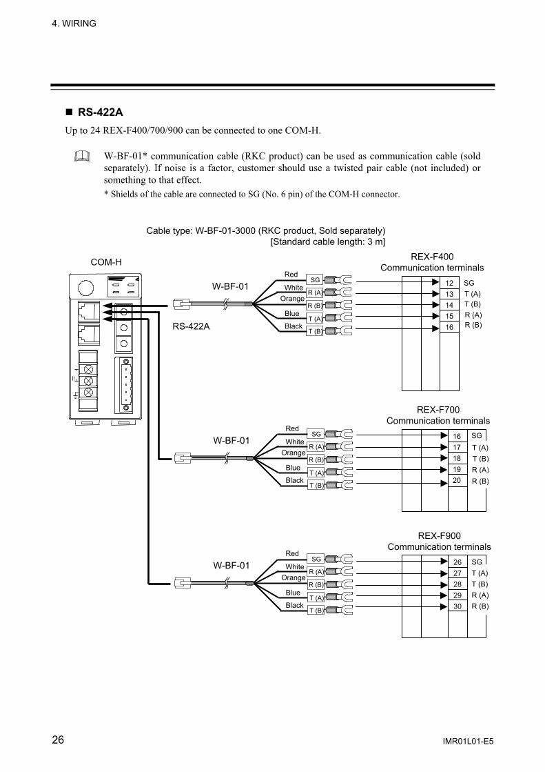
RS-422A Up to 24 REX-F400/700/900 can be connected to one COM-H.
W-BF-01* communication cable (RKC product) can be used as communication cable (sold separately). If noise is a factor, customer should use a twisted pair cable (not included) or something to that effect. * Shields of the cable are connected to SG (No. 6 pin) of the COM-H connector.
COM-H
SG
T (B) T (A)
1213141516
1617181920
2627282930
SGT (A)T (B)
R (A)R (B)
R (A)R (B)
RS-422A
SGT (A)T (B)R (A)R (B)
Cable type: W-BF-01-3000 (RKC product, Sold separately) [Standard cable length: 3 m]
REX-F400 Communication terminals
W-BF-01 White
Black
Blue
Red
Orange
T (A)
SG
T (B)
R (A)
R (B)
W-BF-01 White
Black
Blue
Red
Orange
T (A)
SG
T (B)
R (A)
R (B)
REX-F700 Communication terminals
REX-F900 Communication terminals
W-BF-01 White
Black
Blue
Red
Orange
T (A)
SG
T (B)
R (A)
R (B)

4. WIRING
IMR01L01-E5 27
Multi-drop connecting example
Up to 24 controllers
COM-H Junction terminals
SG
T (B)
T (A) 1213141516
R (A)R (B)
SG
T (B) T (A)
1213141516
R (A)R (B)
RS-422A
REX-F400 Communication
terminals
REX-F400 Communication terminals
W-BF-01 White
Black
Blue
Red
Orange
T (A)
SG
T (B)
R (A)
R (B)
4. WIRING
IMR01L01-E5 28
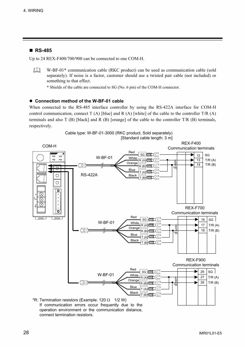
RS-485 Up to 24 REX-F400/700/900 can be connected to one COM-H.
W-BF-01* communication cable (RKC product) can be used as communication cable (sold separately). If noise is a factor, customer should use a twisted pair cable (not included) or something to that effect. * Shields of the cable are connected to SG (No. 6 pin) of the COM-H connector.
Connection method of the W-BF-01 cable When connected to the RS-485 interface controller by using the RS-422A interface for COM-H control communication, connect T (A) [blue] and R (A) [white] of the cable to the controller T/R (A) terminals and also T (B) [black] and R (B) [orange] of the cable to the controller T/R (B) terminals, respectively.
COM-H
Cable type: W-BF-01-3000 (RKC product, Sold separately) [Standard cable length: 3 m]
SG
T/R (B)T/R (A)
12 13 14
RS-422A
W-BF-01 White
Black
Blue
Red
Orange
T (A)
SG
T (B)
R (A)
R (B)
REX-F400 Communication terminals
*R
161718
SG
T/R (B)T/R (A)
W-BF-01 White
Black
Blue
Red
Orange
T (A)
SG
T (B)
R (A)
R (B)
REX-F700 Communication terminals
*R
262728
SG
T/R (B)T/R (A)
*R
*R: Termination resistors (Example: 120 Ω 1/2 W) If communication errors occur frequently due to theoperation environment or the communication distance,connect termination resistors.
REX-F900 Communication terminals
W-BF-01 White
Black
Blue
Red
Orange
T (A)
SG
T (B)
R (A)
R (B)
4. WIRING
IMR01L01-E5 29
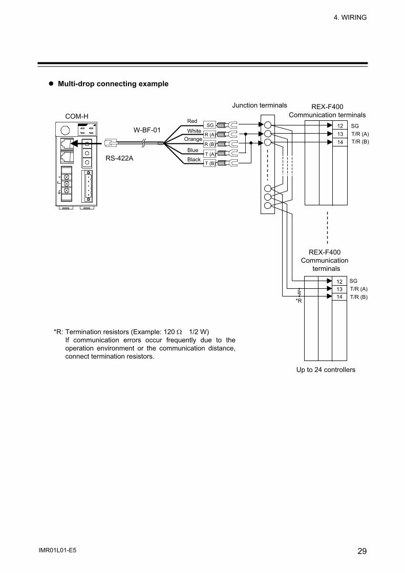
Multi-drop connecting example
121314
SG
T/R (B)T/R (A)
Up to 24 controllers
COM-H Junction terminals
121314
SG
T/R (B)T/R (A)
RS-422A
REX-F400 Communication terminals
REX-F400 Communication
terminals
W-BF-01 White
Black
Blue
Red
Orange
T (A)
SG
T (B)
R (A)
R (B)
*R
*R: Termination resistors (Example: 120 Ω 1/2 W) If communication errors occur frequently due to theoperation environment or the communication distance,connect termination resistors.

4. WIRING
IMR01L01-E5 30
(4) Connection to SA100
Up to 24 SA100 can be connected to one COM-H.
W-BF-01* communication cable (RKC product) can be used as communication cable (sold separately). If noise is a factor, customer should use a twisted pair cable (not included) or something to that effect. * Shields of the cable are connected to SG (No. 6 pin) of the COM-H connector.
Connection method of the W-BF-01/W-BO-01 cable When connected to the RS-485 interface controller by using the RS-422A interface for COM-H control communication, connect T (A) [blue] and R (A) [white] of the cable to the controller T/R (A) connector pin and also T (B) [black] and R (B) [orange] of the cable to the controller T/R (B) connector pin, respectively.
COM-H
Junction terminals
SA100 communication connector (bottom side)
1SG
3 T/R (B)
2 T/R (A)
Pin layout
RS-422A
Cable type: W-BF-01-3000/W-BO-01-3000 (RKC product, Sold separately)[Standard cable length: 3 m]
W-BF-01 White
Black
Blue
Red
Orange
T (A)
SG
T (B)
R (A)
R (B)
W-BO-01 White
Black
RedT/R(A)
T/R(B)
SG
*R
*R: Termination resistors (Example: 120 Ω 1/2 W) If communication errors occur frequently due to theoperation environment or the communication distance, connect termination resistors.
4. WIRING
IMR01L01-E5 31
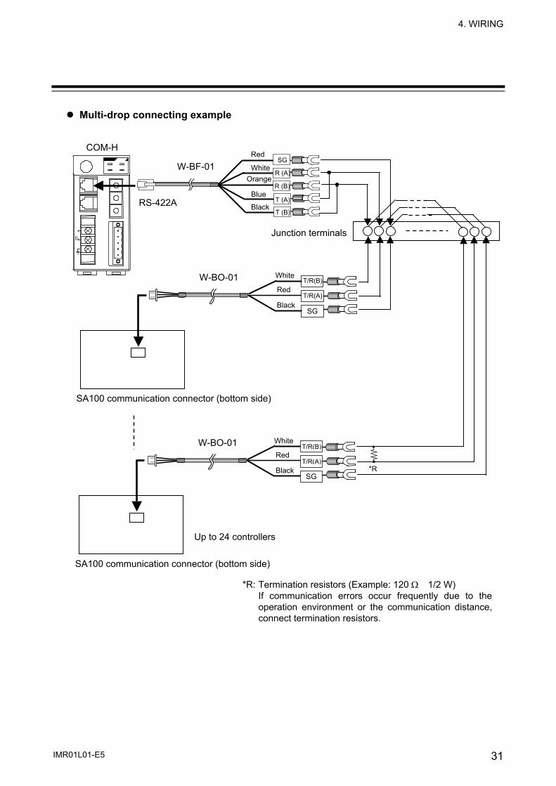
Multi-drop connecting example
COM-H
RS-422A
W-BF-01 White
Black
Blue
Red
Orange
T (A)
SG
T (B)
R (A)
R (B)
Junction terminals
W-BO-01 White
Black
RedT/R(A)
T/R(B)
SG
W-BO-01 White
Black
RedT/R(A)
T/R(B)
SG
SA100 communication connector (bottom side)
SA100 communication connector (bottom side)
Up to 24 controllers
*R
*R: Termination resistors (Example: 120 Ω 1/2 W) If communication errors occur frequently due to the operation environment or the communication distance,connect termination resistors.
4. WIRING
IMR01L01-E5 32
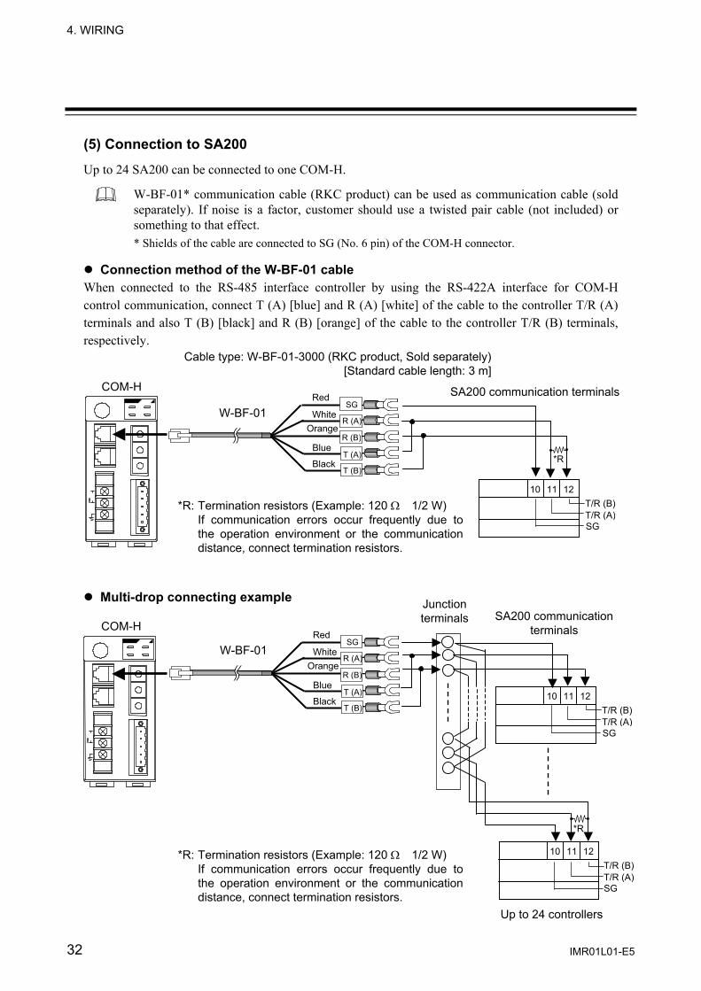
(5) Connection to SA200
Up to 24 SA200 can be connected to one COM-H.
W-BF-01* communication cable (RKC product) can be used as communication cable (sold separately). If noise is a factor, customer should use a twisted pair cable (not included) or something to that effect. * Shields of the cable are connected to SG (No. 6 pin) of the COM-H connector.
Connection method of the W-BF-01 cable
When connected to the RS-485 interface controller by using the RS-422A interface for COM-H control communication, connect T (A) [blue] and R (A) [white] of the cable to the controller T/R (A) terminals and also T (B) [black] and R (B) [orange] of the cable to the controller T/R (B) terminals, respectively. Multi-drop connecting example
Up to 24 controllers
T/R (B)10 11 12
T/R (A)SG
Cable type: W-BF-01-3000 (RKC product, Sold separately)[Standard cable length: 3 m]
COM-H SA200 communication terminals
T/R (B)10 11 12
T/R (A)SG
W-BF-01 White
Black
Blue
Red
Orange
T (A)
SG
T (B)
R (A)
R (B)
COM-H SA200 communication
terminals
T/R (B)
Junctionterminals
10 11 12
T/R (A)SG
W-BF-01 White
Black
Blue
Red
Orange
T (A)
SG
T (B)
R (A)
R (B)
*R
*R
*R: Termination resistors (Example: 120 Ω 1/2 W) If communication errors occur frequently due tothe operation environment or the communicationdistance, connect termination resistors.
*R: Termination resistors (Example: 120 Ω 1/2 W) If communication errors occur frequently due tothe operation environment or the communicationdistance, connect termination resistors.
4. WIRING
IMR01L01-E5 33
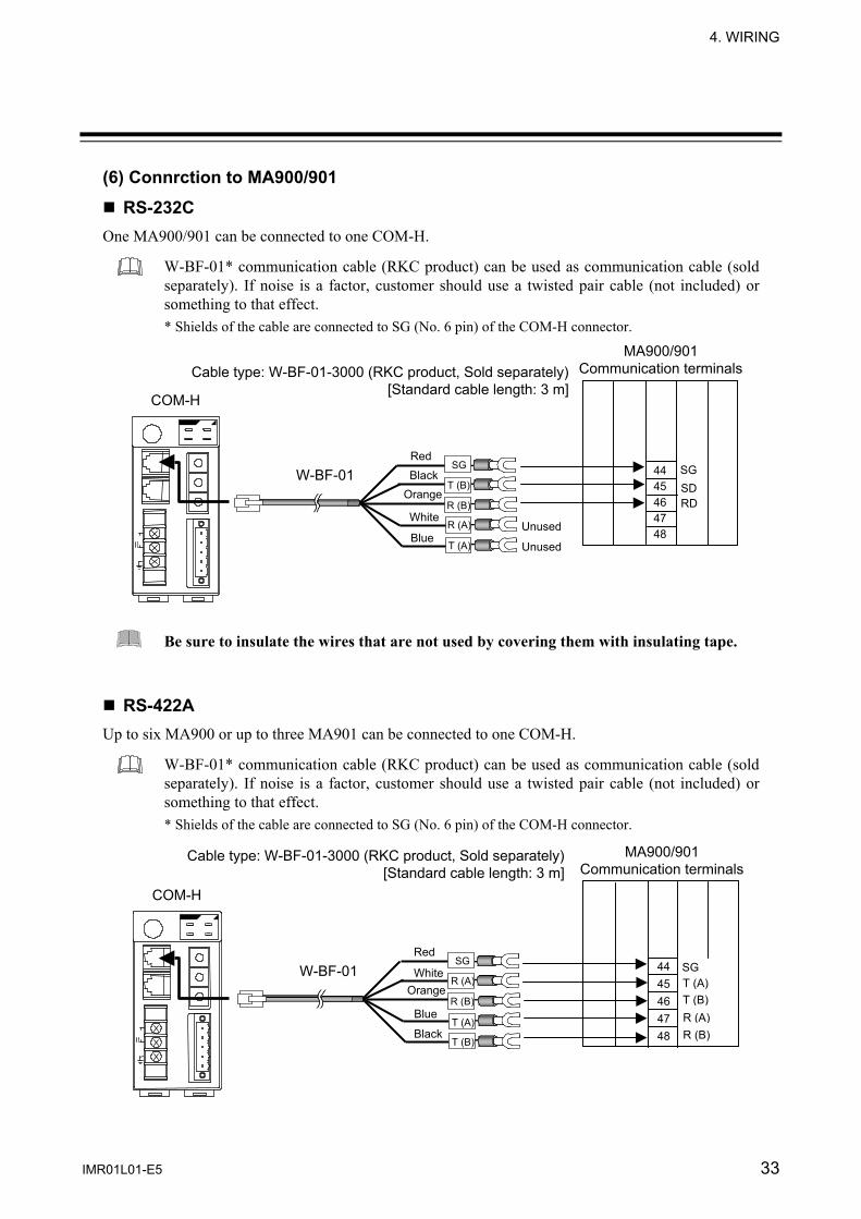
(6) Connrction to MA900/901
RS-232C One MA900/901 can be connected to one COM-H.
W-BF-01* communication cable (RKC product) can be used as communication cable (sold separately). If noise is a factor, customer should use a twisted pair cable (not included) or something to that effect. * Shields of the cable are connected to SG (No. 6 pin) of the COM-H connector.
Be sure to insulate the wires that are not used by covering them with insulating tape. RS-422A
Up to six MA900 or up to three MA901 can be connected to one COM-H.
W-BF-01* communication cable (RKC product) can be used as communication cable (sold separately). If noise is a factor, customer should use a twisted pair cable (not included) or something to that effect. * Shields of the cable are connected to SG (No. 6 pin) of the COM-H connector.
MA900/901 Communication terminals
44 45 46 47 48
SG
Unused
Unused
COM-H
SD RD
MA900/901 Communication terminals
COM-H
44 45 46 47 48
SG T (A) T (B) R (A) R (B)
W-BF-01 White
Black
Blue
Red
Orange
T (A)
SG
T (B)
R (A)
R (B)
Cable type: W-BF-01-3000 (RKC product, Sold separately)[Standard cable length: 3 m]
W-BF-01
White
Black
Blue
Red
Orange
T (A)
SG
T (B)
R (A)
R (B)
Cable type: W-BF-01-3000 (RKC product, Sold separately)[Standard cable length: 3 m]

4. WIRING
IMR01L01-E5 34
Multi-drop connecting example
MA900/901 Communication terminals
COM-H 44 45 46 47 48
SGT (A)T (B)R (A)R (B)
Junction terminals
44 45 46 47 48
SGT (A)T (B)R (A)R (B)
MA900: Up to 6 controllers MA901: Up to 3 controllers
W-BF-01 White
Black
Blue
Red
Orange
T (A)
SG
T (B)
R (A)
R (B)

3. WIRING
IMR01L01-E5 35
RS-485 Up to six MA900 or up to three MA901 can be connected to one COM-H.
W-BF-01* communication cable (RKC product) can be used as communication cable (sold separately). If noise is a factor, customer should use a twisted pair cable (not included) or something to that effect. * Shields of the cable are connected to SG (No. 6 pin) of the COM-H connector.
Connection method of the W-BF-01 cable When connected to the RS-485 interface controller by using the RS-422A interface for COM-H control communication, connect T (A) [blue] and R (A) [white] of the cable to the controller T/R (A) terminals and also T (B) [black] and R (B) [orange] of the cable to the controller T/R (B) terminals, respectively.
COM-H
MA900/901 Communication terminals
44 45 46 47 48
SG T/R (A)T/R (B)
W-BF-01 White
Black
Blue
Red
Orange
T (A)
SG
T (B)
R (A)
R (B)
Cable type: W-BF-01-3000 (RKC product, Sold separately)[Standard cable length: 3 m]
*R
*R: Termination resistors (Example: 120 Ω 1/2 W) If communication errors occur frequently due to theoperation environment or the communication distance,connect termination resistors.
4. WIRING
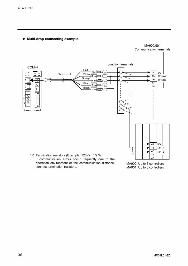
IMR01L01-E5 36
Multi-drop connecting example
MA900: Up to 6 controllers MA901: Up to 3 controllers
COM-H
MA900/901 Communication terminals
44 45 46 47 48
SGT/R (A)T/R (B)
44 45 46 47 48
SGT/R (A)T/R (B)
W-BF-01 White
Black
Blue
Red
Orange
T (A)
SG
T (B)
R (A)
R (B)
Junction terminals
*R *R: Termination resistors (Example: 120 Ω 1/2 W) If communication errors occur frequently due to theoperation environment or the communication distance,connect termination resistors.
3. WIRING
IMR01L01-E5 37
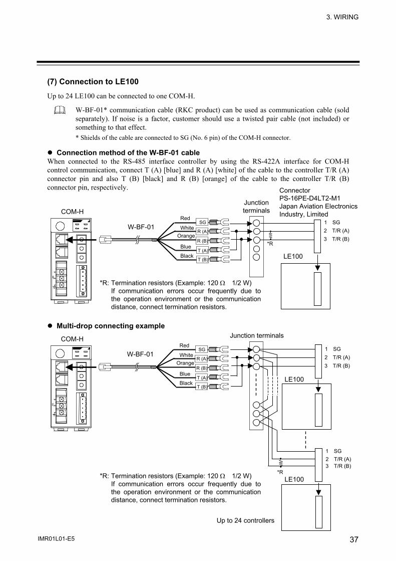
(7) Connection to LE100
Up to 24 LE100 can be connected to one COM-H.
W-BF-01* communication cable (RKC product) can be used as communication cable (sold separately). If noise is a factor, customer should use a twisted pair cable (not included) or something to that effect. * Shields of the cable are connected to SG (No. 6 pin) of the COM-H connector.
Connection method of the W-BF-01 cable
When connected to the RS-485 interface controller by using the RS-422A interface for COM-H control communication, connect T (A) [blue] and R (A) [white] of the cable to the controller T/R (A) connector pin and also T (B) [black] and R (B) [orange] of the cable to the controller T/R (B) connector pin, respectively.
Multi-drop connecting example
Connector PS-16PE-D4LT2-M1 Japan Aviation Electronics Industry, Limited COM-H
3 T/R (B)
Junction terminals
2 T/R (A)1 SG
LE100
COM-H
3 T/R (B)2 T/R (A)1 SG
LE100
3 T/R (B)2 T/R (A)1 SG
Junction terminals
Up to 24 controllers
W-BF-01 White
Black
Blue
Red
Orange
T (A)
SG
T (B)
R (A)
R (B)
W-BF-01 White
Black
Blue
Red
Orange
T (A)
SG
T (B)
R (A)
R (B)
*R
*R
*R: Termination resistors (Example: 120 Ω 1/2 W) If communication errors occur frequently due to the operation environment or the communicationdistance, connect termination resistors.
*R: Termination resistors (Example: 120 Ω 1/2 W) If communication errors occur frequently due tothe operation environment or the communication distance, connect termination resistors.
LE100

4. WIRING
IMR01L01-E5 38
(8) Connection to REX-PG410
RS-422A Up to 24 REX-PG410 can be connected to one COM-H.
W-BF-01* communication cable (RKC product) can be used as communication cable (sold separately). If noise is a factor, customer should use a twisted pair cable (not included) or something to that effect. * Shields of the cable are connected to SG (No. 6 pin) of the COM-H connector.
Multi-drop connecting example
Cable type: W-BF-01-3000 (RKC product, Sold separately)[Standard cable length: 3 m]
REX-PG410 Communication terminals
W-BF-01 White
Black
Blue
Red
Orange
T (A)
SG
T (B)
R (A)
R (B)
RS-422A
COM-H
12 13 14 15 16 R (B) R (A) T (B) T (A) SG
*R *R
COM-H REX-PG410 Communication terminals
Junction terminals
12 13 14 15 16
12 13 14 15 16R (B)R (A)T (B)T (A)SG
R (B)R (A)T (B)T (A)SG
*R *R
Up to 24 controllers
W-BF-01 White
Black
Blue
Red
Orange
T (A)
SG
T (B)
R (A)
R (B)
RS-422A
*R: Termination resistors (Example: 120 Ω 1/2 W)If communication errors occur frequently due tothe operation environment or the communicationdistance, connect termination resistors.
*R: Termination resistors (Example: 120 Ω 1/2 W)If communication errors occur frequently due tothe operation environment or the communicationdistance, connect termination resistors.
3. WIRING
IMR01L01-E5 39
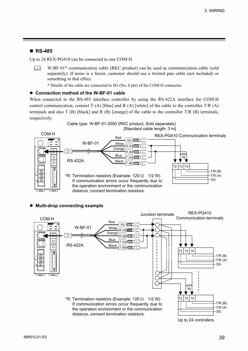
RS-485 Up to 24 REX-PG410 can be connected to one COM-H.
W-BF-01* communication cable (RKC product) can be used as communication cable (sold separately). If noise is a factor, customer should use a twisted pair cable (not included) or something to that effect. * Shields of the cable are connected to SG (No. 6 pin) of the COM-H connector.
Connection method of the W-BF-01 cable When connected to the RS-485 interface controller by using the RS-422A interface for COM-H control communication, connect T (A) [blue] and R (A) [white] of the cable to the controller T/R (A) terminals and also T (B) [black] and R (B) [orange] of the cable to the controller T/R (B) terminals, respectively. Multi-drop connecting example
Cable type: W-BF-01-3000 (RKC product, Sold separately) [Standard cable length: 3 m]
*R
12 13 14 T/R (B)T/R (A)SG
COM-H REX-PG410 Communication terminals
W-BF-01 White
Black
Blue
Red
Orange
T (A)
SG
T (B)
R (A)
R (B)
RS-422A
COM-H
12 13 14 T/R (B)T/R (A)SG
12 13 14 T/R (B)T/R (A)SG
*R
REX-PG410 Communication terminals
Junction terminals
Up to 24 controllers
W-BF-01 White
Black
Blue
Red
Orange
T (A)
SG
T (B)
R (A)
R (B)
RS-422A
*R: Termination resistors (Example: 120 Ω 1/2 W)If communication errors occur frequently due tothe operation environment or the communicationdistance, connect termination resistors.
*R: Termination resistors (Example: 120 Ω 1/2 W)If communication errors occur frequently due tothe operation environment or the communicationdistance, connect termination resistors.

40 IMR01L01-E5
5. SETTING
5.1 DeviceNet Setting 5.1.1 Node address setting To identify each device connected to the network, it is necessary to set a different address to each device (node). For the DeviceNet, as it is possible to connect up to 64 devices including a master to the network, node address (MAC ID) from 0 to 63 can be set. For this setting, use a small blade screwdriver.
Set the address such that it is different to the other addresses on the same line. Otherwise, problems or malfunction may result.
54
32 1 09
876
54
32 1 09
876
Node address setting switch
COM-H
MSD: High-order digit setting (set value × 10)
LSD: Low-order digit setting (set value × 1)
Setting range: 0 to 63 (Factory set value: 63)
Fig. 5-1 Node address setting switch
The above figure is open-style connector type. The figure of micro-style connector type is the same as a open-style connector type.
To prevent electric shock or instrument failure, always turn off the power before setting the switch.
To prevent electric shock or instrument failure, never touch any section other than those instructed in this manual.
WARNING!
5. SETTING
IMR01L01-E5 41
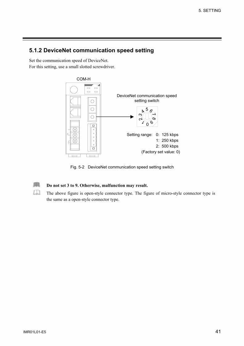
5.1.2 DeviceNet communication speed setting Set the communication speed of DeviceNet. For this setting, use a small slotted screwdriver.
54
32 1 09
876
DeviceNet communication speed setting switch
Setting range: 0: 125 kbps 1: 250 kbps 2: 500 kbps (Factory set value: 0)
COM-H
Fig. 5-2 DeviceNet communication speed setting switch
Do not set 3 to 9. Otherwise, malfunction may result.
The above figure is open-style connector type. The figure of micro-style connector type is the same as a open-style connector type.
5. SETTING
IMR01L01-E5 42
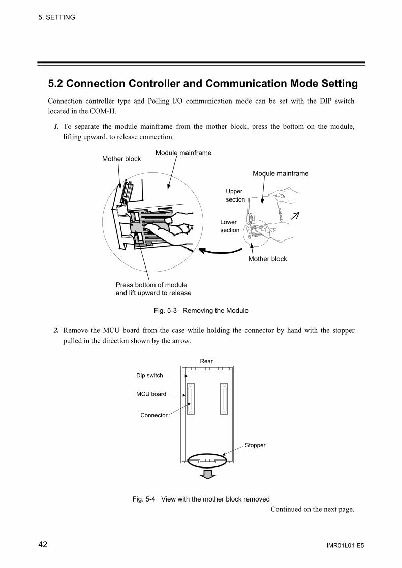
5.2 Connection Controller and Communication Mode Setting Connection controller type and Polling I/O communication mode can be set with the DIP switch located in the COM-H.
1. To separate the module mainframe from the mother block, press the bottom on the module, lifting upward, to release connection.
Fig. 5-3 Removing the Module
2. Remove the MCU board from the case while holding the connector by hand with the stopper pulled in the direction shown by the arrow.
Rear
MCU board
Connector
Dip switch
Stopper
Fig. 5-4 View with the mother block removed Continued on the next page.
Press bottom of module and lift upward to release
Mother block Module mainframe
Upper section
Mother block
Module mainframe
Lower section

5. SETTING
IMR01L01-E5 43
Continued from the previous page.
3. Connection controller and communication mode can be set with the DIP switch located in the COM-H.
Fig 5-5 Location of DIP switch
Connection controller setting Switch number
1 Connection controller model
OFF SR Mini HG ON CB100/400/500/700/900
REX-F400/700/900 SA100/200 MA900/901 LE100 REX-PG410
Factory set value: OFF (SR Mini HG)
Communication mode setting Setting of communicate mode is necessary when it uses Polling I/O communication.
Switch number
2 Communication mode
OFF Communication mode A (Compatible mode) ON Communication mode B (Expansion mode)
Factory set value: OFF (Communication mode A)
For the communication mode A (compatible mode) and communication mode B (expansion mode), refer to 6.2.2 Polling I/O communication (P. 59).
1 2 3 4 5 6 7 8
ON
1 2 3 4 5 6 7 8
ON DIP switch
ON
OFF
MCU board
Connector
5. SETTING
IMR01L01-E5 44
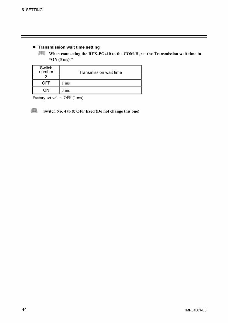
Transmission wait time setting When connecting the REX-PG410 to the COM-H, set the Transmission wait time to “ON (3 ms).”
Switch number
3 Transmission wait time
OFF 1 ms
ON 3 ms
Factory set value: OFF (1 ms)
Switch No. 4 to 8: OFF fixed (Do not change this one)

5. SETTING
IMR01L01-E5 45
5.3 Controller Communication Setting COM-H communication setting
Set a controller communication setting switch of COM-H to become the same value as communication speed and bit configuration of controller connecting with COM-H. For this setting, use a small slotted screwdriver.
COM-H
Setting range: 0 to 8(Factory set value: 0)
876
543210FEDC B A9
Controller communication setting switch
Fig. 5-6 Controller communication setting switch
Setting SR Mini HG communication speed Data bit configuration
0 9600 bps Data 8-bit, without parity, Stop 1-bit
1 9600 bps Data 7-bit, Odd parity, Stop 1-bit
2 9600 bps Data 7-bit, Even parity, Stop 1-bit
3 4800 bps Data 8-bit, without parity, Stop 1-bit
4 4800 bps Data 7-bit, Odd parity, Stop 1-bit
5 4800 bps Data 7-bit, Even parity, Stop 1-bit
6 19200 bps Data 8-bit, without parity, Stop 1-bit
7 19200 bps Data 7-bit, Odd parity, Stop 1-bit
8 19200 bps Data 7-bit, Even parity, Stop 1-bit
Do not set 9 to F. Otherwise, malfunction may result.
Select controller communication setting to become the same as setting of controller.
The above figure is open-style connector type. The figure of micro-style connector type is the same as a open-style connector type.
5. SETTING
IMR01L01-E5 46
Communication setting of the controller side Communication speed and data bit configuration setting
Set the same communication speed and data bit configuration for both the controller and the COM-H. Address setting • An address of SR Mini HG sets it with H-PCP module. Address setting value always set “0.” In
address setting except 0, DeviceNet communication is impossible. • Address setting range of REX-F400/700/900, CB100/400/500/700/900, SA100/200, MA900/901,
LE100 and REX-PG410 is from 1 to 24. When setting the address, always set from “1.”
For communication setting on each controller, refer to Instruction Manual of the following. • SR Mini HG SYSTEM:
SR Mini HG SYSTEM Communication Quick Manual (IMS01V02-E ) SR Mini HG SYSTEM Communication Instruction Manual (IMSRM09-E ) Power supply/CPU module H-PCP-J Instruction Manual (IMS01J02-E )
• REX-F400/700/900: REX-F400/F700/F900 Communication Instruction Manual (IM900F10-E )
• CB100/400/500/700/900: CB100/CB400/CB500/CB700/CB900 Communication Instruction Manual (IMCB03-E )
• SA100: SA100 Communication Instruction Manual (IMR01J02-E )
• SA200: SA200 Communication Instruction Manual (IMR01D02-E )
• MA900/901: MA900/MA901 Communication Instruction Manual (IMR01H02-E )
• LE100: LE100 Communication Instruction Manual (IMR01C02-E )
• REX-PG410: REX-PG410 Communication Instruction Manual (IM41PG02-E )
IMR01L01-E5 47
6. DeviceNet COMMUNICATIONS
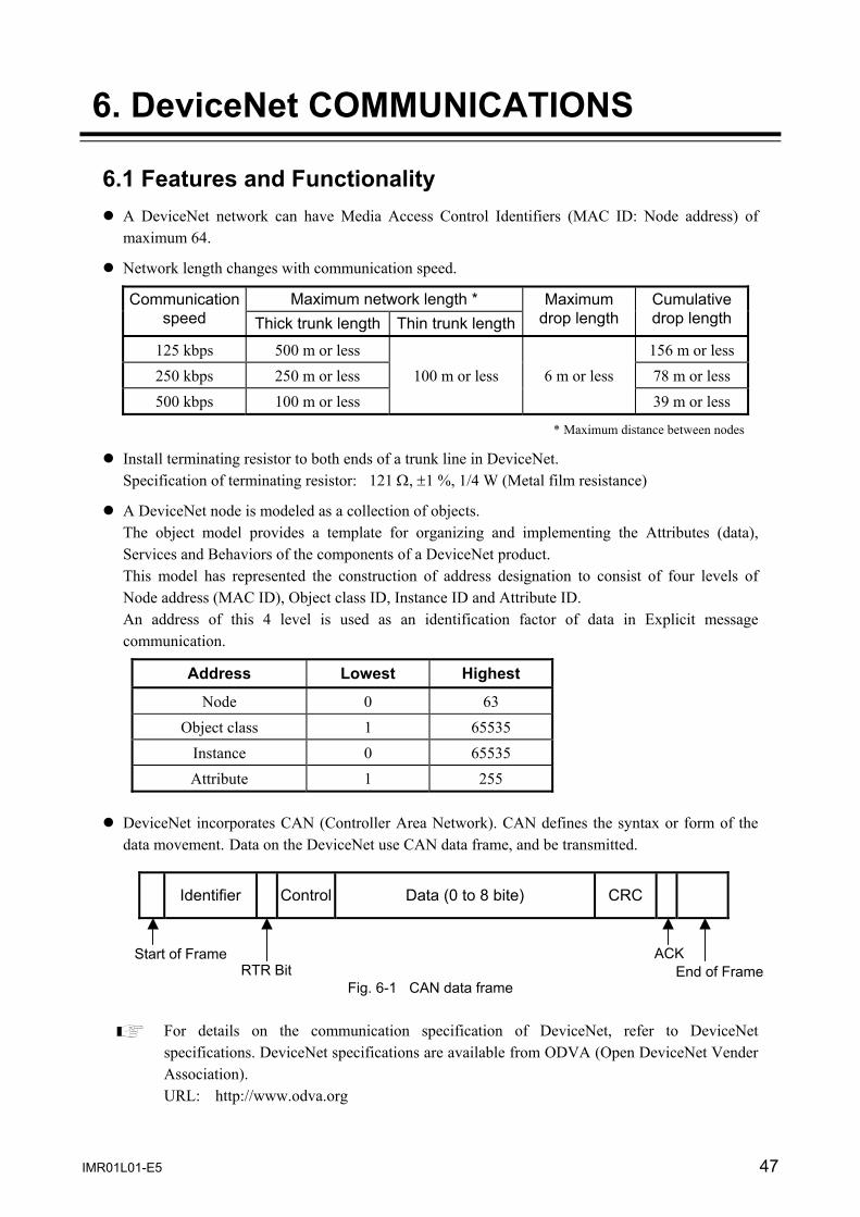
6.1 Features and Functionality A DeviceNet network can have Media Access Control Identifiers (MAC ID: Node address) of
maximum 64.
Network length changes with communication speed.
Maximum network length * Communication speed Thick trunk length Thin trunk length
Maximum drop length
Cumulative drop length
125 kbps 500 m or less 156 m or less250 kbps 250 m or less 100 m or less 6 m or less 78 m or less 500 kbps 100 m or less 39 m or less
* Maximum distance between nodes
Install terminating resistor to both ends of a trunk line in DeviceNet. Specification of terminating resistor: 121 Ω, ±1 %, 1/4 W (Metal film resistance)
A DeviceNet node is modeled as a collection of objects. The object model provides a template for organizing and implementing the Attributes (data), Services and Behaviors of the components of a DeviceNet product. This model has represented the construction of address designation to consist of four levels of Node address (MAC ID), Object class ID, Instance ID and Attribute ID. An address of this 4 level is used as an identification factor of data in Explicit message communication.
Address Lowest Highest
Node 0 63 Object class 1 65535
Instance 0 65535 Attribute 1 255
DeviceNet incorporates CAN (Controller Area Network). CAN defines the syntax or form of the data movement. Data on the DeviceNet use CAN data frame, and be transmitted.
Identifier Control Data (0 to 8 bite) CRC
Fig. 6-1 CAN data frame
For details on the communication specification of DeviceNet, refer to DeviceNet specifications. DeviceNet specifications are available from ODVA (Open DeviceNet Vender Association). URL: http://www.odva.org
ACK RTR Bit
Start of Frame End of Frame
6. DeviceNet COMMUNICATIONS
IMR01L01-E5 48
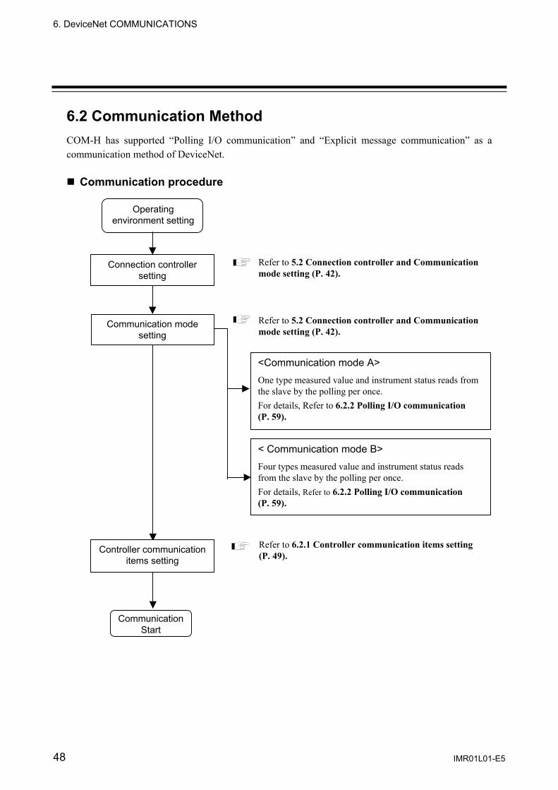
6.2 Communication Method COM-H has supported “Polling I/O communication” and “Explicit message communication” as a communication method of DeviceNet. Communication procedure
Connection controller setting
Refer to 5.2 Connection controller and Communication mode setting (P. 42).
Communication Start
Refer to 6.2.1 Controller communication items setting (P. 49).
Operating environment setting
Communication mode setting
<Communication mode A> One type measured value and instrument status reads from the slave by the polling per once. For details, Refer to 6.2.2 Polling I/O communication (P. 59).
< Communication mode B> Four types measured value and instrument status reads from the slave by the polling per once. For details, Refer to 6.2.2 Polling I/O communication (P. 59).
Controller communication items setting
Refer to 5.2 Connection controller and Communication mode setting (P. 42).

6. DeviceNet COMMUNICATIONS
IMR01L01-E5 49
6.2.1 Controller communication items setting Thirty controller communication items can be set to the COM-H. This setting can be made by using the configuration tool.
Time-out may occur if trying to read any COM-H parameter from the configuration tool while in Polling I/O communication between the master station and COM-H. When reading or setting the parameters by the configuration tool, stop I/O polling at the master station.
The communication items are stored in the inside of COM-H, and are held in case of power off. For communication items in shipment, refer to Communication items of shipment (P. 57).
Setting procedure 1. Connect PC (Personal computer) to COM-H with DeviceNet.
2. Install the EDS file of COM-H on the configuration tool.
Communication mode A and B are available for EDS files. Therefore, install the EDS file in the mode used.
• EDS file for communicate mode A (Compatible mode) • EDS file for communicate mode B (Expansion mode)
For communication mode, refer to 6.2.2 Polling I/O communication (P. 59).
3. Set the DeviceNet to the on-line state by using the configuration tool to open the COM-H property screen. <Reference screen 1: Configuration tool made by OMRON>
Continued on the next page.
Set the identification code of communication items.

6. DeviceNet COMMUNICATIONS
IMR01L01-E5 50
Continued from the previous page.
<Reference screen 2: Configuration tool made by Rockwell>
4. With property screen, sets identification code of controller communication items in the parameter from 1 to 47.
For identification code, refer to 6.3. Communication Items List (P. 67).
Set the identification code of communication item.

6. DeviceNet COMMUNICATIONS
IMR01L01-E5 51
Parameter setting example of Polling I/O communication Parameter setting example at used the SR Mini HG. - Measurement items: Temperature measured input value, Heat-side manipulated output, Cool-side manipulated output, Control RUN/STOP state - Setting items: Temperature set value, Alarm 1 set value, Alarm 2 set value, Control RUN/STOP transfer - Controller status: Alarm 1 status, Alarm 2 status, Heater break alarm status, Burnout status - Number of maximum connection channels: 10 channels Conduct parameter set according to the procedure described below.
1. Selects identification code of polling data from the communication items list, and sets it in the parameter from 1 to 8.
Continued on the next page.
1 Data01 ID 2 Data02 ID 3 Data03 ID 4 Data04 ID 5 Data05 ID 6 Data06 ID 7 Data07 ID 8 Data08 ID
30 Data30 ID
Identification code
Name
19761 (0x4D31) Temperature input measured value 20273 (0x4F31) Heat-side manipulated output 20274 (0x4F32) Cool-side manipulated output 21330 (0x5352) Control RUN/STOP state 21297 (0x5331) Temperature set value16689 (0x4131) Alarm 1 set value 16690 (0x4132) Alarm 2 set value 21330 (0x5352) Control RUN/STOP transfer
Set to identification code Measurement
items
Setting items
Parameters on the configuration
Identification code of communication items list.
6. DeviceNet COMMUNICATIONS
IMR01L01-E5 52
Continued from the previous page.
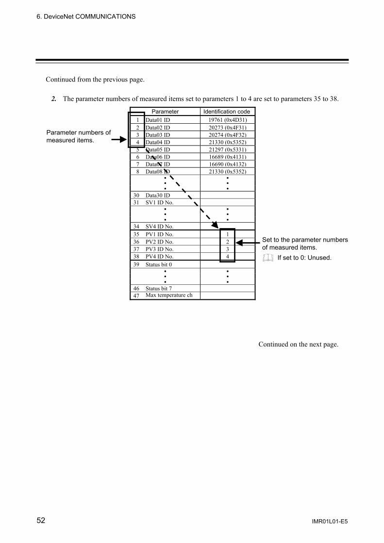
2. The parameter numbers of measured items set to parameters 1 to 4 are set to parameters 35 to 38.
Continued on the next page.
Parameter Identification code1 Data01 ID 19761 (0x4D31) 2 Data02 ID 20273 (0x4F31)3 Data03 ID 20274 (0x4F32)4 Data04 ID 21330 (0x5352)5 Data05 ID 21297 (0x5331)6 Data06 ID 16689 (0x4131)7 Data07 ID 16690 (0x4132)8 Data08 ID 21330 (0x5352)
30 Data30 ID31 SV1 ID No.
34 SV4 ID No.35 PV1 ID No. 1 36 PV2 ID No. 237 PV3 ID No. 338 PV4 ID No. 439 Status bit 0
46 Status bit 747 Max temperature ch
Parameter numbers of measured items.
Set to the parameter numbers of measured items.
If set to 0: Unused.
6. DeviceNet COMMUNICATIONS
IMR01L01-E5 53
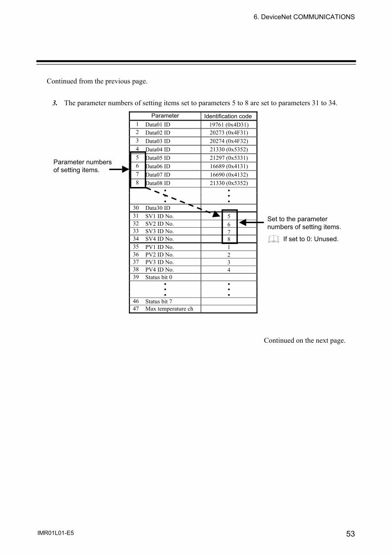
Continued from the previous page. 3. The parameter numbers of setting items set to parameters 5 to 8 are set to parameters 31 to 34.
Continued on the next page.
Parameter Identification code1 Data01 ID 19761 (0x4D31) 2 Data02 ID 20273 (0x4F31) 3 Data03 ID 20274 (0x4F32) 4 Data04 ID 21330 (0x5352) 5 Data05 ID 21297 (0x5331) 6 Data06 ID 16689 (0x4131) 7 Data07 ID 16690 (0x4132) 8 Data08 ID 21330 (0x5352)
30 Data30 ID 31 SV1 ID No. 532 SV2 ID No. 633 SV3 ID No. 734 SV4 ID No. 835 PV1 ID No. 1 36 PV2 ID No. 237 PV3 ID No. 338 PV4 ID No. 439 Status bit 0
46 Status bit 7 47 Max temperature ch
Set to the parameter numbers of setting items.
Parameter numbers of setting items.
If set to 0: Unused.
6. DeviceNet COMMUNICATIONS
IMR01L01-E5 54
Continued from the previous page.
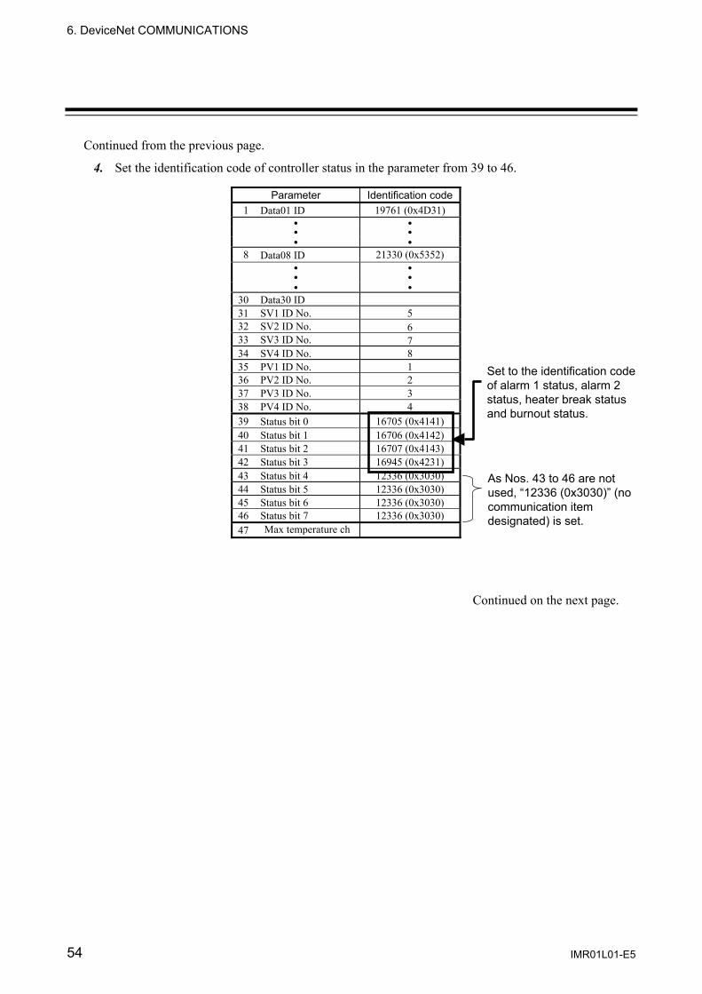
4. Set the identification code of controller status in the parameter from 39 to 46.
Continued on the next page.
Parameter Identification code1 Data01 ID 19761 (0x4D31)
8 Data08 ID 21330 (0x5352)
30 Data30 ID31 SV1 ID No. 532 SV2 ID No. 633 SV3 ID No. 734 SV4 ID No. 835 PV1 ID No. 136 PV2 ID No. 237 PV3 ID No. 338 PV4 ID No. 439 Status bit 0 16705 (0x4141) 40 Status bit 1 16706 (0x4142)41 Status bit 2 16707 (0x4143)42 Status bit 3 16945 (0x4231)43 Status bit 4 12336 (0x3030)44 Status bit 5 12336 (0x3030)45 Status bit 6 12336 (0x3030)46 Status bit 7 12336 (0x3030)47 Max temperature ch
Set to the identification code of alarm 1 status, alarm 2 status, heater break status and burnout status.
As Nos. 43 to 46 are not used, “12336 (0x3030)” (no communication item designated) is set.
6. DeviceNet COMMUNICATIONS
IMR01L01-E5 55
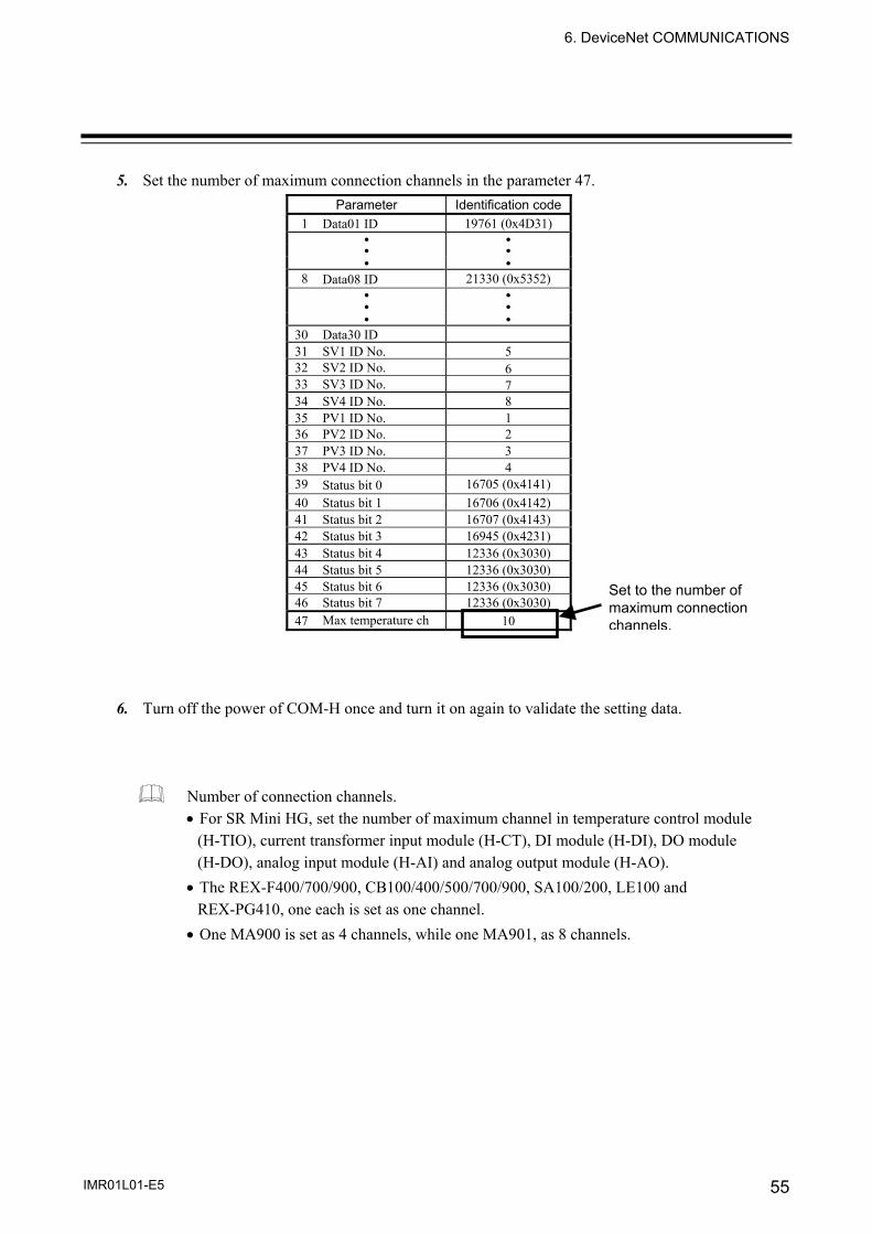
5. Set the number of maximum connection channels in the parameter 47.
6. Turn off the power of COM-H once and turn it on again to validate the setting data.
Number of connection channels. • For SR Mini HG, set the number of maximum channel in temperature control module
(H-TIO), current transformer input module (H-CT), DI module (H-DI), DO module (H-DO), analog input module (H-AI) and analog output module (H-AO).
• The REX-F400/700/900, CB100/400/500/700/900, SA100/200, LE100 and REX-PG410, one each is set as one channel.
• One MA900 is set as 4 channels, while one MA901, as 8 channels.
Parameter Identification code1 Data01 ID 19761 (0x4D31)
8 Data08 ID 21330 (0x5352)
30 Data30 ID31 SV1 ID No. 532 SV2 ID No. 633 SV3 ID No. 734 SV4 ID No. 835 PV1 ID No. 136 PV2 ID No. 237 PV3 ID No. 338 PV4 ID No. 439 Status bit 0 16705 (0x4141) 40 Status bit 1 16706 (0x4142)41 Status bit 2 16707 (0x4143)42 Status bit 3 16945 (0x4231)43 Status bit 4 12336 (0x3030)44 Status bit 5 12336 (0x3030)45 Status bit 6 12336 (0x3030)46 Status bit 7 12336 (0x3030)47 Max temperature ch 10
Set to the number of maximum connection channels.
6. DeviceNet COMMUNICATIONS
IMR01L01-E5 56
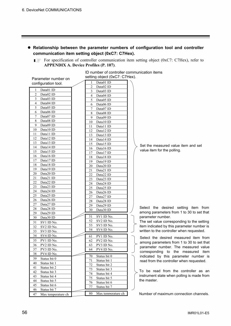
Relationship between the parameter numbers of configuration tool and controller communication item setting object (0xC7: C7Hex).
For specification of controller communication item setting object (0xC7: C7Hex), refer to APPENDIX A. Device Profiles (P. 107).
ID number of controller communication items setting object (0xC7: C7Hex).Parameter number on
configuration tool. 1 Data01 ID2 Data02 ID3 Data03 ID4 Data04 ID5 Data05 ID6 Data06 ID7 Data07 ID8 Data08 ID9 Data09 ID
10 Data10 ID11 Data11 ID12 Data12 ID13 Data13 ID14 Data14 ID15 Data15 ID16 Data16 ID17 Data17 ID18 Data18 ID19 Data19 ID20 Data20 ID21 Data21 ID22 Data22 ID23 Data23 ID24 Data24 ID25 Data25 ID26 Data26 ID27 Data27 ID28 Data28 ID29 Data29 ID30 Data30 ID
51 SV1 ID No.52 SV2 ID No.53 SV3 ID No.54 SV4 ID No.
61 PV1 ID No.62 PV2 ID No.63 PV3 ID No.64 PV4 ID No.
70 Status bit 071 Status bit 172 Status bit 273 Status bit 374 Status bit 475 Status bit 576 Status bit 677 Status bit 7
80 Max temperature ch
1 Data01 ID 2 Data02 ID 3 Data03 ID 4 Data04 ID 5 Data05 ID 6 Data06 ID 7 Data07 ID 8 Data08 ID 9 Data09 ID
10 Data10 ID 11 Data11 ID 12 Data12 ID 13 Data13 ID 14 Data14 ID 15 Data15 ID 16 Data16 ID 17 Data17 ID 18 Data18 ID 19 Data19 ID 20 Data20 ID 21 Data21 ID 22 Data22 ID 23 Data23 ID 24 Data24 ID 25 Data25 ID 26 Data26 ID 27 Data27 ID 28 Data28 ID 29 Data29 ID 30 Data30 ID 31 SV1 ID No. 32 SV2 ID No. 33 SV3 ID No. 34 SV4 ID No. 35 PV1 ID No. 36 PV2 ID No. 37 PV3 ID No. 38 PV4 ID No. 39 Status bit 0 40 Status bit 1 41 Status bit 2 42 Status bit 3 43 Status bit 4 44 Status bit 5 45 Status bit 6 46 Status bit 7 47 Max temperature ch
Set the measured value item and set value item for the polling.
Select the desired setting item from among parameters from 1 to 30 to set that parameter number. The set value corresponding to the setting item indicated by this parameter number is written to the controller when requested.
Select the desired measured item fromamong parameters from 1 to 30 to set thatparameter number. The measured valuecorresponding to the measured itemindicated by this parameter number isread from the controller when requested.
To be read from the controller as aninstrument state when polling is made fromthe master.
Number of maximum connection channels.
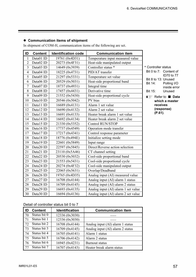
6. DeviceNet COMMUNICATIONS
IMR01L01-E5 57
Communication items of shipment In shipment of COM-H, communication items of the following are set. ID Content Identification code Communication item
1 Data01 ID 19761 (0x4D31) Temperature input measured value 2 Data02 ID 20273 (0x4F31) Heat-side manipulated output 3 Data03 ID 14649 (0x3939) Controller status * 4 Data04 ID 18225 (0x4731) PID/AT transfer 5 Data05 ID 21297 (0x5331) Temperature set value 6 Data06 ID 20529 (0x5031) Heat-side proportional band 7 Data07 ID 18737 (0x4931) Integral time 8 Data08 ID 17457 (0x4431) Derivative time 9 Data09 ID 21552 (0x5430) Heat-side proportional cycle
10 Data10 ID 20546 (0x5042) PV bias 11 Data11 ID 16689 (0x4131) Alarm 1 set value 12 Data12 ID 16690 (0x4132) Alarm 2 set value 13 Data13 ID 16691 (0x4133) Heater break alarm 1 set value 14 Data14 ID 16692 (0x4134) Heater break alarm 2 set value 15 Data15 ID 21330 (0x5352) Control RUN/STOP 16 Data16 ID 17737 (0x4549) Operation mode transfer 17 Data17 ID 17217 (0x4341) Control response parameter 18 Data18 ID 18776 (0x494E) Initialize setting mode 19 Data19 ID 22601 (0x5849) Input range 20 Data20 ID 22597 (0x5845) Direct/Reverse action selection 21 Data21 ID 23110 (0x5A46) CT channel setting 22 Data22 ID 20530 (0x5032) Cool-side proportional band 23 Data23 ID 21553 (0x5431) Cool-side proportional cycle 24 Data24 ID 20274 (0x4F32) Cool-side manipulated output 25 Data25 ID 22065 (0x5631) Overlap/Deadband 26 Data26 ID 19765 (0x4D35) Analog input (AI) measured value 27 Data27 ID 16708 (0x4144) Analog input (AI) alarm 1 status 28 Data28 ID 16709 (0x4145) Analog input (AI) alarm 2 status 29 Data29 ID 16693 (0x4135) Analog input (AI) alarm 1 set value 30 Data30 ID 16694 (0x4136) Analog input (AI) alarm 2 set value
Detail of controller status bit 0 to 7 ID Content Identification Communication item70 Status bit 0 12336 (0x3030) −−−71 Status bit 1 12336 (0x3030) −−− 72 Status bit 2 16708 (0x4144) Analog input (AI) alarm 1 status 73 Status bit 3 16709 (0x4145) Analog input (AI) alarm 2 status 74 Status bit 4 16705 (0x4141) Alarm 1 status 75 Status bit 5 16706 (0x4142) Alarm 2 status 76 Status bit 6 16945 (0x4231) Burnout status 77 Status bit 7 16707 (0x4143) Heater break alarm status
* Controller status Bit 0 to 7: Content of ID70 to 77 Bit 8 to 13: Unused Bit 14: Polling I/O
inside error Bit 15: Unused
Refer to ■ Data which a master receives (response) (P.61).

6. DeviceNet COMMUNICATIONS
IMR01L01-E5 58
If a PLC manufactured by OMRON is used and the Connection controller setting (dip switch No. 1) is tuned to ON (CB100/400/500/700/900, REX-F400/700/900, SA100/200, MA900/901, LE100, REX-PG410), set the PLC Message Timer to 10000 ms. ⟨Setting procedure of Message Timer⟩
1. Click the PLC name being displayed. 2. Click [Device] → [Parameter] → [Edit] in the menu. Thus “Edit Device
Parameters” dialog box is displayed. 3. Click the [Message Timer] tab to set the COM-H Message Timer to 10000 ms.
< Message Timer, Configuration tool made by OMRON>
Set the Message Timer of COM-H to “10000 ms.” (In this example, Message Timer of MAC ID 63)

6. DeviceNet COMMUNICATIONS
IMR01L01-E5 59
6.2.2 Polling I/O communication Polling I/O communication is the communication that master and slave always execute transmission and reception of data. Used always when checking data items such as measured values, etc. Either one type or four types of measured value to be read can be selected by polling made once according to the communication mode in Polling I/O communication.
Communication mode Select either communicate mode A or B. - Communication mode A (Compatible mode):
For one time of polling 1 from the master, sends one measured value 2 and instrument status from the slave.
- Communication mode B (Expansion mode): For one time of polling 1 from the master, sends four measured value 2 and instrument status from the slave.
1 Each sends data type, channel number and set value to slave. 2 For data type, refer to A difference of polling data by communicate mode (P. 62).
For setting method of communication mode, refer to 5.2 Connection Controller and Communication Mode Setting (P. 42).
Fig. 6-1 Outline of polling I/O communication
Continued on the next page.
Request
Always data send
Master
Slave COM-H
RKC
Controller
Data type Channel number
Set value
Response
<Communication mode A>One Measured value
Controller status <Communication mode B>
Four Measured value Controller status
DviceNet
RKC Communication
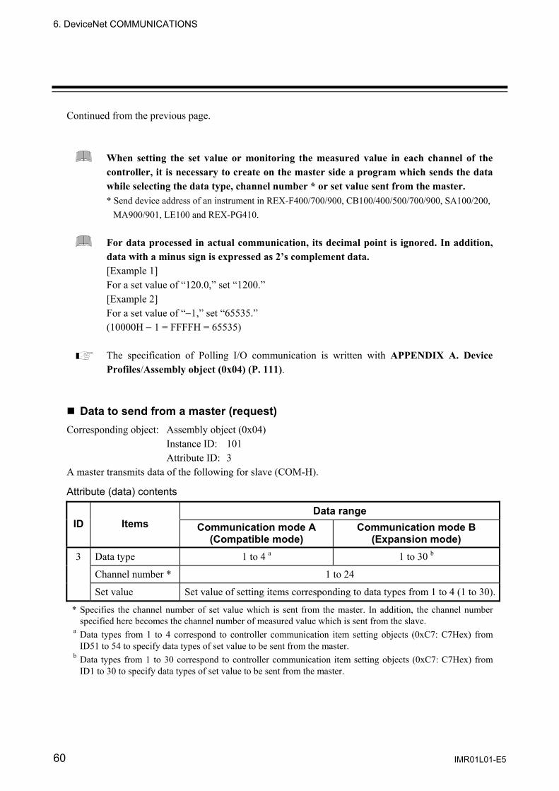
6. DeviceNet COMMUNICATIONS
IMR01L01-E5 60
Continued from the previous page.
When setting the set value or monitoring the measured value in each channel of the controller, it is necessary to create on the master side a program which sends the data while selecting the data type, channel number * or set value sent from the master. * Send device address of an instrument in REX-F400/700/900, CB100/400/500/700/900, SA100/200,
MA900/901, LE100 and REX-PG410.
For data processed in actual communication, its decimal point is ignored. In addition, data with a minus sign is expressed as 2’s complement data. [Example 1] For a set value of “120.0,” set “1200.” [Example 2] For a set value of “−1,” set “65535.” (10000H − 1 = FFFFH = 65535)
The specification of Polling I/O communication is written with APPENDIX A. Device Profiles/Assembly object (0x04) (P. 111).
Data to send from a master (request)
Corresponding object: Assembly object (0x04) Instance ID: 101 Attribute ID: 3
A master transmits data of the following for slave (COM-H).
Attribute (data) contents
Data range ID Items Communication mode A
(Compatible mode) Communication mode B
(Expansion mode) 3 Data type 1 to 4 a 1 to 30 b
Channel number * 1 to 24
Set value Set value of setting items corresponding to data types from 1 to 4 (1 to 30).
* Specifies the channel number of set value which is sent from the master. In addition, the channel number specified here becomes the channel number of measured value which is sent from the slave.
a Data types from 1 to 4 correspond to controller communication item setting objects (0xC7: C7Hex) from ID51 to 54 to specify data types of set value to be sent from the master.
b Data types from 1 to 30 correspond to controller communication item setting objects (0xC7: C7Hex) from ID1 to 30 to specify data types of set value to be sent from the master.

6. DeviceNet COMMUNICATIONS
IMR01L01-E5 61
Data which a master receives (response) Corresponding object: Assembly object (0x04)
Instance ID: 100 Attribute ID: 3
For the transmission from a master, slave (COM-H) calls data of the following from controller, and transmit to a master.
Attribute (data) contents
Data range ID Items Communication mode A
(Compatible mode) Communication mode B
(Expansion mode) 3 Measured value Measured value corresponding to
the data type required from the master.
Four types measured value specified from ID 61 to 64 by controller communication item setting object (0 x C7).
Controller status Word type data Bit 0 to 7: Controller status 1 Bit 8 to 13: Unused Bit 14: Polling I/O inside error 2 Bit 15: Unused
1 The lowest bit of the item designated by IDs 70 to 77 of Controller Communication Item Setting Object (0xC7: C7Hex) is set to controller status Bits 0 to 7. • When alarm has occurred, become “1.” • When alarm has not occurred, become “0.”
2 • When no response from the controller for Polling I/O Request, become “1.” • When response of controller for Polling I/O Request is normal, become “0.”

6. DeviceNet COMMUNICATIONS
IMR01L01-E5 62
A difference of polling data by communicate mode Communication mode A (Compatible mode)
Measured value corresponding to types of request data to be sent from the master are sent to the master from the COM-H as response data. - Data type 1
Request data from a master: The set value data specified with ID 51 of 0xC7 *. Response data from COM-H: The measured value data specified with ID 61 of 0xC7 *.
- Data type 2
Request data from a master: The set value data specified with ID 52 of 0xC7 *. Response data from COM-H: The measured value data specified with ID 62 of 0xC7 *.
- Data type 3
Request data from a master: The set value data specified with ID 53 of 0xC7 *. Response data from COM-H: The measured value data specified with ID 63 of 0xC7 *.
- Data type 4
Request data from a master: The set value data specified with ID 54 of 0xC7 *. Response data from COM-H: The measured value data specified with ID 64 of 0xC7 *.
* Controller communication item setting object (0xC7: C7Hex)
<Set value and measured value corresponding to data type>
ID of controller communication item setting object (0xC7: C7Hex) Data type
Set value Measurement value 1 ID51 ID612 ID52 ID62 3 ID53 ID63 4 ID54 ID64
Communication mode B (Expansion mode)
<Measurement value> The following four types of measured value corresponding to the set value of request data to be sent from the master are sent to the master from the COM-H as response data regardless of these data types. - The measured value data specified with ID 61 of 0xC7 *. - The measured value data specified with ID 62 of 0xC7 *. - The measured value data specified with ID 63 of 0xC7 *. - The measured value data specified with ID 64 of 0xC7 *.
* Controller communication item setting object (0xC7: C7Hex)
<Set value> The set value of request data to be sent from the master becomes that of the set item specified from among controller communication item setting objects ID1 to 30.

6. DeviceNet COMMUNICATIONS
IMR01L01-E5 63
6.2.3 Explicit message communication Explicit message communication uses an Explicit message defined with DeviceNet, and be communication to execute transmission and reception of data between nodes when it is necessary. Explicit message communication is executed like the following, when COM-H (slave) is connected to a master instrument with DeviceNet, and controller is connected to COM-H.
In Explicit message communication, not only data relating to the controller bur also all of the attributes (data) described in APPENDIX A. Device Profiles (P. 107) are subject to being sent or received.
When read data
If the node address (MAC ID), service code (0EH: Get_Attribute_Single), object class ID, instance ID and attribute ID are sent from the master, the node address (MAC ID) thus sent and service code (0EH + 80H *) as well as the data requested are sent from the slave.
* 80H has shown that it is a response message.
Fig. 6-2 Outline of Explicit message communication (data read)
Service code 14H of [Error response] has shown that it is error response. For Error code of [Error response], refer to DeviceNet specifications.
[Normal response]
Request
Data send
Master
Slave COM-H
RKC
Controller
Node address (MAC ID)Service code (0EH)
Object class ID Instance ID Attribute ID
Response Node address (MAC ID)
Service code (0EH + 80H) Request data
[Error response]
Request
Master
Slave COM-H
Node address (MAC ID)Service code (0EH)
Object class ID Instance ID Attribute ID
Response Node address (MAC ID)
Service code (14H + 80H) Error code
DeviceNet
RKC Communication
Polling
DeviceNet
If data items such as objectclass ID, instance ID andattribute ID are out of thesetting range, an error codeis returned as an errorresponse. However, if theerror response is sent fromthe controller or if there isno response, no error codeis returned.
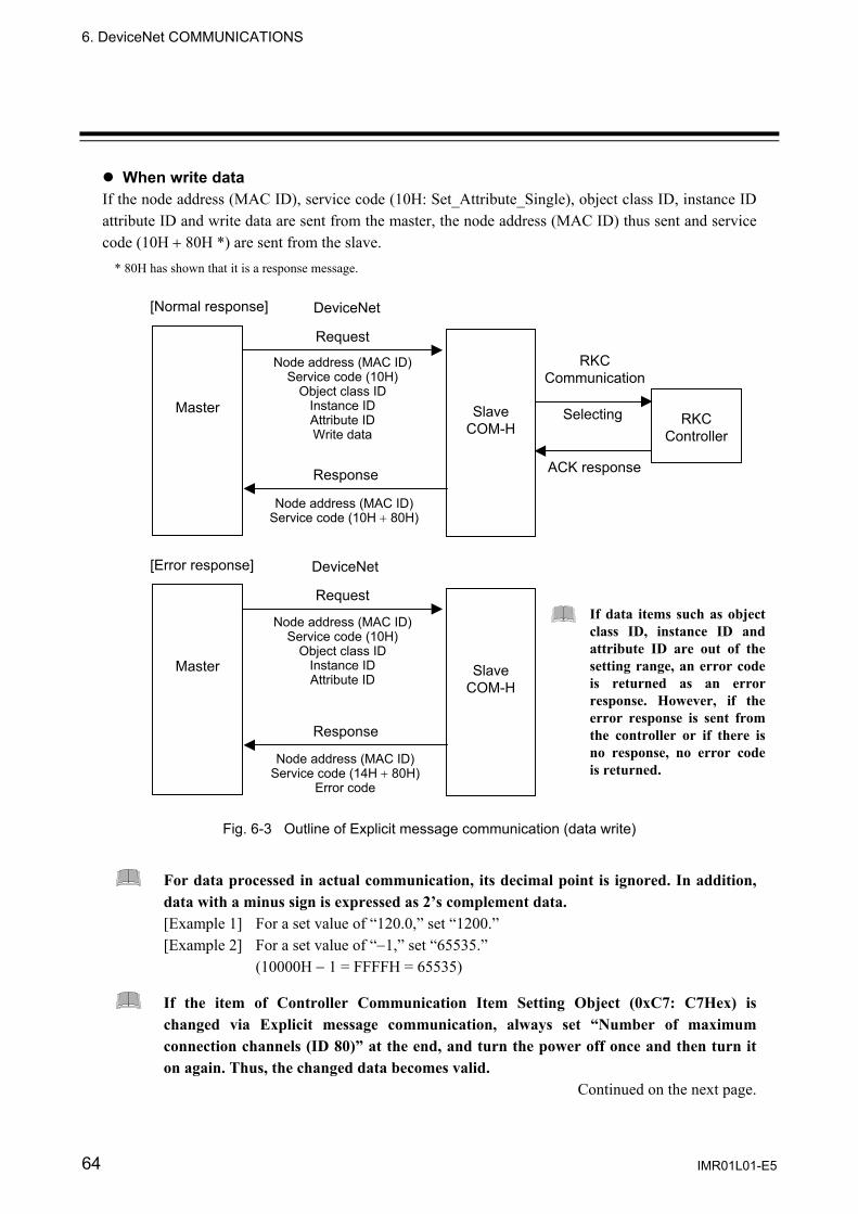
6. DeviceNet COMMUNICATIONS
IMR01L01-E5 64
When write data If the node address (MAC ID), service code (10H: Set_Attribute_Single), object class ID, instance ID attribute ID and write data are sent from the master, the node address (MAC ID) thus sent and service code (10H + 80H *) are sent from the slave.
* 80H has shown that it is a response message.
Fig. 6-3 Outline of Explicit message communication (data write)
For data processed in actual communication, its decimal point is ignored. In addition, data with a minus sign is expressed as 2’s complement data. [Example 1] For a set value of “120.0,” set “1200.” [Example 2] For a set value of “−1,” set “65535.” (10000H − 1 = FFFFH = 65535)
If the item of Controller Communication Item Setting Object (0xC7: C7Hex) is changed via Explicit message communication, always set “Number of maximum connection channels (ID 80)” at the end, and turn the power off once and then turn it on again. Thus, the changed data becomes valid.
Continued on the next page.
Request
ACK response
Master
Slave COM-H
RKC
Controller
Response
[Normal response]
Request
Master
Slave COM-H
Response
[Error response]
Node address (MAC ID)Service code (10H)
Object class ID Instance ID Attribute ID Write data
Node address (MAC ID)Service code (10H + 80H)
Node address (MAC ID)Service code (10H)
Object class ID Instance ID Attribute ID
Node address (MAC ID)Service code (14H + 80H)
Error code
RKC Communication
Selecting
DeviceNet
DeviceNet
If data items such as objectclass ID, instance ID andattribute ID are out of thesetting range, an error codeis returned as an errorresponse. However, if theerror response is sent fromthe controller or if there isno response, no error codeis returned.

6. DeviceNet COMMUNICATIONS
IMR01L01-E5 65
Continued from the previous page.
Service code 14H of [Error response] has shown that it is error response.
For Error code of [Error response], refer to DeviceNet specifications.
The explicit message communication specification of data to be related to SR Mini HG is written with APPENDIX A. Device Profiles/Temperature controller object (0x64) (P. 115).
Data setting example
Describe data setting example of the SR Mini HG it with the following.
Corresponding object: Temperature controller object (0x64) Object class ID: 64 Instance ID: 1 to 24 Attribute ID: 1 to 30
Object instances (Instance IDs) from 1 to 24 correspond to channels from 1 to 20 of the SR Mini HG. However, temperature input data, analog input (AI) data and CT input data exist in the SR Mini HG and each of them is used from channel 1. Therefore, the temperature input, analog input (AI) and CT input are not identified by Instance ID, but by the contents of data (namely, Attribute ID).
[Example] When set 100 in “Alarm 1 set value” of Temperature input channel 1
(Node address of COM-H: 1) Node address (MAC ID): 1 Service code: 10H (Set_Attribute_Single) Object class ID: 64 Instance ID: 1 (Channel 1) Attribute ID: 11 (Temperature input, Alarm 1 set value) Write data: 100
When “Analog input measured value” of Analog input channel 1 is read out from
slave. (Node address of COM-H: 1) Node address (MAC ID): 1 Service code: 0EH (Get_Attribute_Single) Object class ID: 64 Instance ID: 1 (Channel 1) Attribute ID: 26 (Analog input measured value)
Continued on the next page.
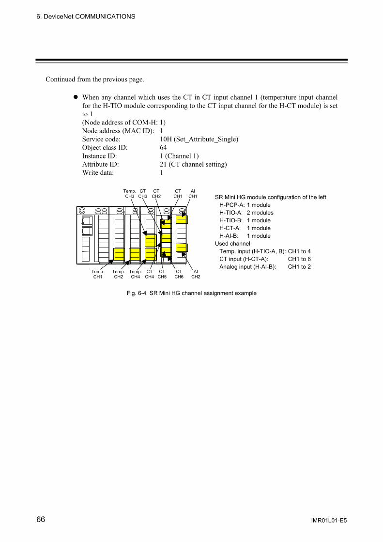
6. DeviceNet COMMUNICATIONS
IMR01L01-E5 66
Continued from the previous page.
When any channel which uses the CT in CT input channel 1 (temperature input channel for the H-TIO module corresponding to the CT input channel for the H-CT module) is set to 1 (Node address of COM-H: 1) Node address (MAC ID): 1 Service code: 10H (Set_Attribute_Single) Object class ID: 64 Instance ID: 1 (Channel 1) Attribute ID: 21 (CT channel setting) Write data: 1
Fig. 6-4 SR Mini HG channel assignment example
CT CH3
Temp. CH3
AICH1
CTCH1
CTCH2
Temp. CH1
AICH2
CTCH6
CTCH5
Temp. CH4
Temp. CH2
CT CH4
SR Mini HG module configuration of the leftH-PCP-A: 1 module H-TIO-A: 2 modules H-TIO-B: 1 module H-CT-A: 1 module H-AI-B: 1 module
Used channel Temp. input (H-TIO-A, B): CH1 to 4 CT input (H-CT-A): CH1 to 6 Analog input (H-AI-B): CH1 to 2

6. DeviceNet COMMUNICATIONS
IMR01L01-E5 67
6.3 Communication Items List ID code (Identification code): ID code is written using both of decimal and hexadecimal (in parentheses) numbers.
Attribute: RO: Read only
Correspond to Service code: 0EH (Get_Attribute_Single) of DeviceNet. For data request of a master, data is read from slave.
R/W: Read and Write Correspond to Service code: 0EH (Get_Attribute_Single) /Service code: 10H (Set_Attribute_Single) of DeviceNet. In Get_Attribute_Single, data is read for data request of a master from Slave. In Set_Attribute_Single, write in data for Slave from a master.
WO: Write only Correspond to Service code: 10H (Set_Attribute_Single) of DeviceNet. In Set_Attribute_Single, write in data for Slave from a master.
6.3.1 SR Mini HG
ID code Identi-fier
Communication items
Attri-bute ID code Identi
-fierCommunication
items Attri-bute
16689 (0x4131)
A1 Alarm 1 set value R/W 16709 (0x4145)
AE AI alarm 2 status RO
16690 (0x4132)
A2 Alarm 2 set value R/W 16710 (0x4146)
AF TI alarm 1 status RO
16691 (0x4133)
A3 Heater break alarm (HBA) set value 1
R/W 16711 (0x4147)
AG TI alarm 2 status RO
16692 (0x4134)
A4 Heater break alarm (HBA) set value 2
R/W 16712 (0x4148)
AH CT module Heater break alarm status
RO
16693 (0x4135)
A5 AI alarm 1 set value R/W 16714 (0x414A)
AJ Overall alarm status RO
16694 (0x4136)
A6 AI alarm 2 set value R/W 16720 (0x4150)
AP Control loop break alarm (LBA) status
RO
16695 (0x4137)
A7 Event DO extension alarm set value
R/W 16722 (0x4152)
AR Alarm interlock release WO
16696 (0x4138)
A8 TI alarm 1 set value R/W 16726 (0x4156)
AV Input error determination point (high limit)
R/W
16697 (0x4139)
A9 TI alarm 2 set value R/W 16727 (0x4157)
AW Input error determination point (low limit)
R/W
16705 (0x4141)
AA Alarm 1 status RO 16945 (0x4231)
B1 Burnout status RO
16706 (0x4142)
AB Alarm 2 status RO 16946 (0x4232)
B2 TI burnout status RO
16707 (0x4143)
AC Heater break alarm (HBA) status
RO 17201 (0x4331)
C1 Local/Computer transfer
RO
16708 (0x4144)
AD AI alarm 1 status RO 17202 (0x4332)
C2 CC-Link Selecting flag
RO
Continued on the next page.

6. DeviceNet COMMUNICATIONS
IMR01L01-E5 68
Continued from the previous page.
ID code Identi-fier
Communication items
Attri-bute ID code Identi
-fierCommunication
items Attri-bute
17206 (0x4336)
C6 Control loop break alarm (LBA) time
R/W 18225 (0x4731)
G1 PID/AT transfer R/W
17217 (0x4341)
CA Control response parameters
R/W 18242 (0x4742)
GB AT bias R/W
17228 (0x434C)
CL Module initialization R/W 18482 (0x4832)
H2 DI using selection R/W
17238 (0x4356)
CV AO zooming high limit R/W 18483 (0x4833)
H3 Cascade DI function selection
R/W
17239 (0x4357)
CW AO zooming low limit R/W 18484 (0x4834)
H4 PCP module DI function selection
R/W
17457 (0x4431)
D1 Derivative time R/W 18497 (0x4841)
HA Alarm 1 differential gap R/W
17478 (0x4446)
DF Number of alarm delay times
R/W 18498 (0x4842)
HB Alarm 2 differential gap R/W
17479 (0x4447)
DG Number of TI alarm delay times
R/W 18499 (0x4843)
HC AI alarm 1 differential gap
R/W
17480 (0x4448)
DH Number of HBA trigger poins
R/W 18500 (0x4844)
HD Temperature rise completion range
R/W
17713 (0x4531)
E1 Event DI corresponding channel selection 1
R/W 18501 (0x4845)
HE Temperature rise completion status
RO
17714 (0x4532)
E2 Event DI corresponding channel selection 2
R/W 18502 (0x4846)
HF AI alarm 2 differential gap
R/W
17715 (0x4533)
E3 Event DI corresponding channel selection 3
R/W 18503 (0x4847)
HG Event DO extension alarm differential gap
R/W
17716 (0x4534)
E4 Event DI corresponding channel selection 4
R/W 18504 (0x4848)
HH Setting change rate limiter
R/W
17737 (0x4549)
EI Operation mode transfer R/W 18505 (0x4849)
HI TI alarm 1 differential gap
R/W
17738 (0x454A
)
EJ TI operation mode transfer
R/W 18506 (0x484A)
HJ TI alarm 2 differential gap
R/W
17739 (0x454B)
EK Temperature rise completion hold function
R/W 18512 (0x4850)
HP LBA use selection R/W
17746 (0x4552)
ER Error code RO
18515 (0x4853)
HS Temperature rise completion trigger
R/W
17969 (0x4631)
F1 Digital filter R/W 18518 (0x4856)
HV AO display scale high R/W
17970 (0x4632)
F2 AI digital filter R/W 18519 (0x4857)
HW AO display scale low R/W
17971 (0x4633)
F3 TI digital filter R/W 18737 (0x4931)
I1 Integral time R/W
18006 (0x4656)
FV Positioning adjustment counter
R/W 18766 (0x494E)
IN Initial setting mode R/W
Continued on the next page.
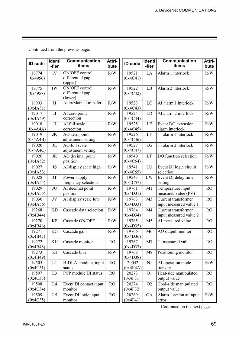
6. DeviceNet COMMUNICATIONS
IMR01L01-E5 69
Continued from the previous page.
ID code Identi-fier
Communication items
Attri-bute ID code Identi
-fierCommunication
items Attri-bute
18774 (0x4956)
IV ON/OFF control differential gap (upper)
R/W 19521 (0x4C41)
LA Alarm 1 interlock R/W
18775 (0x4957)
IW ON/OFF control differential gap (lower)
R/W 19522 (0x4C42)
LB Alarm 2 interlock R/W
18993 (0x4A31)
J1 Auto/Manual transfer R/W 19523 (0x4C43)
LC AI alarm 1 interlock R/W
19017 (0x4A49)
JI AI zero point correction
R/W 19524 (0x4C44)
LD AI alarm 2 interlock R/W
19018 (0x4A4A)
JJ AI full scale correction
R/W 19525 (0x4C45)
LE Event DO extension alarm interlock
R/W
19019 (0x4A4B)
JK AO zero point adjustment setting
R/W 19526 (0x4C46)
LF TI alarm 1 interlock R/W
19020 (0x4A4C)
JL AO full scale adjustment setting
R/W 19527 (0x4C47)
LG TI alarm 2 interlock R/W
19026 (0x4A52)
JR AO decimal point position
R/W 19540 (0x4C54)
LT DO function selection R/W
19027 (0x4A53)
JS AI display scale high R/W 19541 (0x4C55)
LU Event DI logic circuit selection
R/W
19028 (0x4A54)
JT Power supply frequency selection
R/W 19543 (0x4C57)
LW Event DI delay timer setting
R/W
19029 (0x4A55)
JU AI decimal point position
R/W 19761 (0x4D31)
M1 Temperature input measured value (PV)
RO
19030 (0x4A56)
JV AI display scale low R/W 19763 (0x4D33)
M3 Current transformer input measured value 1
RO
19268 (0x4B44)
KD Cascade data selection R/W 19764 (0x4D34)
M4 Current transformer input measured value 2
RO
19270 (0x4B46)
KF Cascade ON/OFF R/W 19765 (0x4D35)
M5 AI measured value RO
19271 (0x4B47)
KG Cascade gain R/W 19766 (0x4D36)
M6 AO output monitor RO
19272 (0x4B48)
KH Cascade monitor RO 19767 (0x4D37)
M7 TI measured value RO
19273 (0x4B49)
KI Cascade bias R/W 19768 (0x4D38)
M8 Positioning monitor RO
19505 (0x4C31)
L1 H-DI-A module input status
RO 20042 (0x4E4A)
NJ AI operation mode transfer
R/W
19507 (0x4C33)
L3 PCP module DI status RO 20273 (0x4F31)
O1 Heat-side manipulated output value
RO
19508 (0x4C34)
L4 Event DI contact input monitor
RO 20274 (0x4F32)
O2 Cool-side manipulated output value
RO
19509 (0x4C35)
L5 Event DI logic input monitor
RO 20289 (0x4F41)
OA Alarm 1 action at input error
R/W
Continued on the next page.

6. DeviceNet COMMUNICATIONS
IMR01L01-E5 70
Continued from the previous page.
ID code Identi-fier
Communication items
Attri-bute ID code Identi
-fierCommunication
items Attri-bute
20290 (0x4F42)
OB Alarm 2 action at input error
R/W 21041 (0x5231)
R1 Event DI type selection 1
R/W
20291 (0x4F43)
OC TI alarm 1 action at input error
R/W 21042 (0x5232)
R2 Event DI type selection 2
R/W
20292 (0x4F44)
OD TI alarm 2 action at input error
R/W 21043 (0x5233)
R3 Event DI type selection 3
R/W
20293 (0x4F45)
OE Manipulated output value at input error
R/W 21044 (0x5234)
R4 Event DI type selection 4
R/W
20296 (0x4F48)
OH Output limiter (high limit)
R/W 21297 (0x5331)
S1 Temperature set value (SV)
R/W
20300 (0x4F4C)
OL Output limiter (low limit)
R/W 21302 (0x5336)
S6 AO output set value R/W
20302 (0x4F4E)
ON Manual output value R/W 21320 (0x5348)
SH Setting limiter (high limit)
R/W
20303 (0x4F4F)
OO Manual Positioning output value
R/W 21324 (0x534C)
SL Setting limiter (low limit)
R/W
20307 (0x4F53)
OS Integrated output limiter
R/W 21330 (0x5352)
SR Control RUN/STOP R/W
20313 (0x4F59)
OY AO corresponding channel setting
R/W 21336 (0x5358)
SX Start determination point
R/W
20529 (0x5031)
P1 Heat-side proportional band
R/W 21552 (0x5430)
T0 Heat-side proportioning cycle time
R/W
20530 (0x5032)
P2 Cool-side proportional band
R/W 21553 (0x5431)
T1 Cool-side proportioning cycle time
R/W
20546 (0x5042)
PB PV bias R/W 21555 (0x5433)
T3 Temperature rise completion soak time
R/W
20547 (0x5043)
PC PV bias (TI module) R/W 21577 (0x5449)
TI Number of event DO extension alarm delay times
R/W
20552 (0x5048)
PH Output change rate limiter (up)
R/W 21578 (0x544A)
TJ Motor time R/W
20556 (0x504C)
PL Output change rate limiter (down)
R/W 21579 (0x544B)
TK Number of AI alarm delay times
R/W
20567 (0x5057)
PW AO output change rate limiter
R/W 22065 (0x5631)
V1 Overlap/Deadband R/W
20787 (0x5133)
Q3 Event DO status RO 22066 (0x5632)
V2 LBA deadband R/W
20788 (0x5134)
Q4 Event DO manual output value
R/W 22067 (0x5633)
V3 Positioning output neutral zone
R/W
20789 (0x5135)
Q5 Event DI logic input monitor
RO 22081 (0x5641)
VA AI moving aberage R/W
Continued on the next page.

6. DeviceNet COMMUNICATIONS
IMR01L01-E5 71
Continued from the previous page.
ID code Identi-fier
Communication items
Attri-bute ID code Identi
-fierCommunication
items Attri-bute
22091 (0x564B)
VK AI input range number R/W 22596 (0x5844)
XD AI alarm 2 type selection
R/W
22096 (0x5650)
VP PCP module DO type selection
R/W 22597 (0x5845)
XE Direct/Reverse action selection
R/W
22097 (0x5651)
VQ PCP module DI type selection
R/W 22598 (0x5846)
XF Event DO function selection
R/W
22099 (0x5653)
VS PCP module DO de-energized selection
R/W 22599 (0x5847)
XG Event DO corresponding channel setting
R/W
22321 (0x5731)
W1 Event DI reversal selection 1
R/W 22600 (0x5848)
XH Event DO mode transfer
R/W
22322 (0x5732)
W2 Event DI reversal selection 2
R/W 22601 (0x5849)
XI Input range number R/W
22323 (0x5733)
W3 Event DI reversal selection 3
R/W 22602 (0x584A)
XJ TI input range number R/W
22324 (0x5734)
W4 Event DI reversal selection 4
R/W 22603 (0x584B)
XK DI function selection R/W
22337 (0x5741)
WA Alarm 1 hold action R/W 22604 (0x584C)
XL Cascade tracking R/W
22338 (0x5742)
WB Alarm 2 hold action R/W 22606 (0x584E)
XN Hot/Cold start selection R/W
22339 (0x5743)
WC AI alarm 1 hold action R/W 22607 (0x584F)
XO AO function selection R/W
22340 (0x5744)
WD AI alarm 2 hold action R/W 22608 (0x5850)
XP TI alarm 1 type R/W
22341 (0x5745)
WE TI alarm 1 hold action R/W 22609 (0x5851)
XQ TI alarm 2 type R/W
22342 (0x5746)
WF TI alarm 2 hold action R/W 22610 (0x5852)
XR Temperature module type
RO
22344 (0x5748)
WH Action at input error (high limit)
R/W 22613 (0x5855)
XU Decimal point position R/W
22348 (0x574C)
WL Action at input error (low limit)
R/W 22614 (0x5856)
XV Display scale high R/W
22577 (0x5831)
X1 Control RUN/STOP holding
R/W 22615 (0x5857)
XW Display scale low R/W
22593 (0x5841)
XA Alarm 1 type selection R/W 23105 (0x5A41)
ZA Memory area number R/W
22594 (0x5842)
XB Alarm 2 type selection R/W 23110 (0x5A46)
ZF CT channel setting R/W
22595 (0x5843)
XC AI alarm 1 type selection
R/W 23128 (0x5A58)
ZX Interval time setting R/W
For details, refer to the SR Mini HG SYSTEM Communication Instruction Manual (IMSRM09-E ) or Power Supply/CPU Module H-PCP-J Instruction Manual (IMS01J02-E ).

6. DeviceNet COMMUNICATIONS
IMR01L01-E5 72
6.3.2 CB100/400/500/700/900
ID code Identi-fier
Communication items
Attri-bute ID code Identi
-fierCommunication
items Attri-bute
16689 (0x4131)
A1 Alarm 1 setting R/W 21297 (0x5331)
S1 Set value (SV) R/W
16690 (0x4132)
A2 Alarm 2 setting R/W 21330 (0x5352)
SR RUN/STOP transfer R/W
16691 (0x4133)
A3 Heater break alarm 1 setting
R/W 21552 (0x5430)
T0 Heat-side proportioning cycle time
R/W
16692 (0x4134)
A4 Heater break alarm 2 setting
R/W 21553 (0x5431)
T1 Cool-side proportioning cycle time
R/W
16693 (0x4135)
A5 Control loop break alarm (LBA) setting
R/W 22065 (0x5631)
V1 Overlap/Deadband R/W
16694 (0x4136)
A6 LBA deadband R/W 22321 (0x5731)
W1 Anti-reset windup R/W
16705 (0x4141)
AA Alarm 1 status RO
16706 (0x4142)
AB Alarm 2 status RO
16945 (0x4231)
B1 Burnout RO
17457 (0x4431)
D1 Derivative time R/W
17746 (0x4552)
ER Error code RO
18225 (0x4731)
G1 Autotuning (AT) R/W
18226 (0x4732)
G2 Self tuning (ST) R/W
18737 (0x4931)
I1 Integral time R/W
19761 (0x4D31)
M1 Measured value (PV) RO
19762 (0x4D32)
M2 Current transformer input 1
RO
19763 (0x4D33)
M3 Current transformer input 2
RO
20529 (0x5031)
P1 Heat-side proportional band
R/W
20530 (0x5032)
P2 Cool-side proportional band
R/W
20546 (0x5042)
PB PV bias R/W
For details, refer to the CB100/CB400/CB500/CB700/CB900 Communication Instruction Manual (IMCB03-E ).
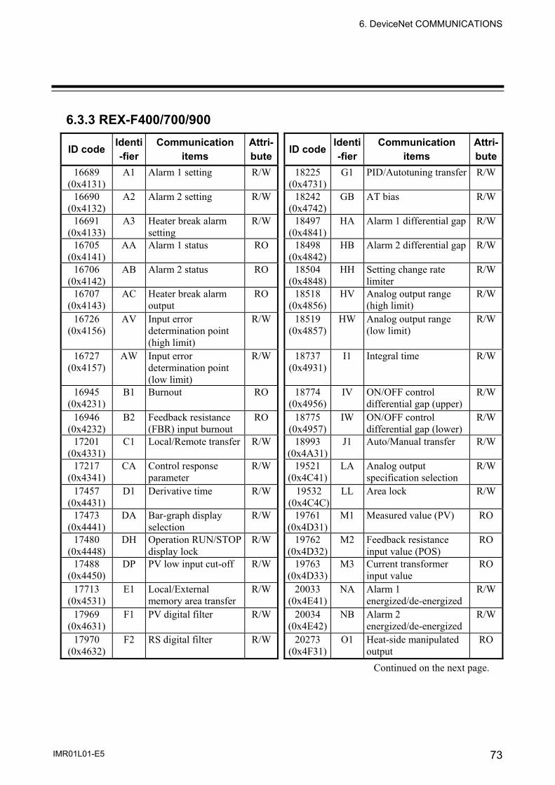
6. DeviceNet COMMUNICATIONS
IMR01L01-E5 73
6.3.3 REX-F400/700/900
ID code Identi-fier
Communication items
Attri-bute ID code Identi
-fierCommunication
items Attri-bute
16689 (0x4131)
A1 Alarm 1 setting R/W 18225 (0x4731)
G1 PID/Autotuning transfer R/W
16690 (0x4132)
A2 Alarm 2 setting R/W 18242 (0x4742)
GB AT bias R/W
16691 (0x4133)
A3 Heater break alarm setting
R/W 18497 (0x4841)
HA Alarm 1 differential gap R/W
16705 (0x4141)
AA Alarm 1 status RO 18498 (0x4842)
HB Alarm 2 differential gap R/W
16706 (0x4142)
AB Alarm 2 status RO 18504 (0x4848)
HH Setting change rate limiter
R/W
16707 (0x4143)
AC Heater break alarm output
RO 18518 (0x4856)
HV Analog output range (high limit)
R/W
16726 (0x4156)
AV Input error determination point (high limit)
R/W 18519 (0x4857)
HW Analog output range (low limit)
R/W
16727 (0x4157)
AW Input error determination point (low limit)
R/W 18737 (0x4931)
I1 Integral time R/W
16945 (0x4231)
B1 Burnout RO 18774 (0x4956)
IV ON/OFF control differential gap (upper)
R/W
16946 (0x4232)
B2 Feedback resistance (FBR) input burnout
RO 18775 (0x4957)
IW ON/OFF control differential gap (lower)
R/W
17201 (0x4331)
C1 Local/Remote transfer R/W 18993 (0x4A31)
J1 Auto/Manual transfer R/W
17217 (0x4341)
CA Control response parameter
R/W 19521 (0x4C41)
LA Analog output specification selection
R/W
17457 (0x4431)
D1 Derivative time R/W 19532 (0x4C4C)
LL Area lock R/W
17473 (0x4441)
DA Bar-graph display selection
R/W 19761 (0x4D31)
M1 Measured value (PV) RO
17480 (0x4448)
DH Operation RUN/STOP display lock
R/W 19762 (0x4D32)
M2 Feedback resistance input value (POS)
RO
17488 (0x4450)
DP PV low input cut-off R/W 19763 (0x4D33)
M3 Current transformer input value
RO
17713 (0x4531)
E1 Local/External memory area transfer
R/W 20033 (0x4E41)
NA Alarm 1 energized/de-energized
R/W
17969 (0x4631)
F1 PV digital filter R/W 20034 (0x4E42)
NB Alarm 2 energized/de-energized
R/W
17970 (0x4632)
F2 RS digital filter R/W 20273 (0x4F31)
O1 Heat-side manipulated output
RO
Continued on the next page.

6. DeviceNet COMMUNICATIONS
IMR01L01-E5 74
Continued from the previous page.
ID code Identi-fier
Communication items
Attri-bute ID code Identi
-fierCommunication
items Attri-bute
20274 (0x4F32)
O2 Cool-side manipulated output
RO 21330 (0x5352)
SR Operation RUN/STOP transfer
R/W
20289 (0x4F41)
OA Alarm 1 action at input error
R/W 21336 (0x5358)
SX Start determination point
R/W
20290 (0x4F42)
OB Alarm 2 action at input error
R/W 21337 (0x5359)
SY Action selection feedback resistance (FBR) input break
R/W
20293 (0x4F45)
OE Manual output at input error
R/W 21552 (0x5430)
T0 Heat-side proportioning cycle time
R/W
20296 (0x4F48)
OH Output limiter (high limit)
R/W 21553 (0x5431)
T1 Cool-side proportioning cycle time
R/W
20300 (0x4F4C)
OL Output limiter (low limit)
R/W 21572 (0x5444)
TD Alarm 1 timer setting R/W
20302 (0x4F4E)
ON Manipulated output value (MV)
R/W 21575 (0x5447)
TG Alarm 2 timer setting R/W
20305 (0x4F51)
OQ Shortest cooling output ON time
R/W 22065 (0x5631)
V1 Overlap/Deadband R/W
20529 (0x5031)
P1 Heat-side proportional band
R/W 22066 (0x5632)
V2 Neutral zone R/W
20530 (0x5032)
P2 Cool-side proportional band
R/W 22337 (0x5741)
WA Alarm 1 hold action selection
R/W
20546 (0x5042)
PB PV bias R/W 22338 (0x5742)
WB Alarm 2 hold action selection
R/W
20552 (0x5048)
PH Output change rate limiter (up)
R/W 22344 (0x5748)
WH Action selection at input error (high limit)
R/W
20556 (0x504C)
PL Output change rate limiter (down)
R/W 22348 (0x574C)
WL Action selection at input error (low limit)
R/W
21057 (0x5241)
RA Local/Computer mode identification
RO 22577 (0x5831)
X1 PV input type selection R/W
21058 (0x5242)
RB RS bias R/W 22593 (0x5841)
XA Alarm 1 action selection
R/W
21074 (0x5252)
RR RS ratio R/W 22594 (0x5842)
XB Alarm 2 action selection
R/W
21297 (0x5331)
S1 Set value (SV) R/W 22597 (0x5845)
XE Direct/Reverse action selection
R/W
21298 (0x5332)
S2 Remote set value (RS) R/W 22600 (0x5848)
XH Square root extraction selection
R/W
21320 (0x5348)
SH Setting limiter (high limit)
R/W 22604 (0x584C)
XL SV tracking selection R/W
21324 (0x534C)
SL Setting limiter (low limit)
R/W 22606 (0x584E)
XN Hot/Cold start selection R/W
Continued on the next page.

6. DeviceNet COMMUNICATIONS
IMR01L01-E5 75
Continued from the previous page.
ID code Identi-fier
Communication items
Attri-bute
22610 (0x5852)
XR RS input type selection
R/W
22613 (0x5855)
XU Decimal point position selection
R/W
22614 (0x5856)
XV Input programmable range (high limit)
R/W
22615 (0x5857)
XW Input programmable range (low limit)
R/W
23105 (0x5A41)
ZA Control area number transfer
R/W
For details, refer to the REX-F400/F700/F900 Communication Instruction Manual (IM900F10-E ).
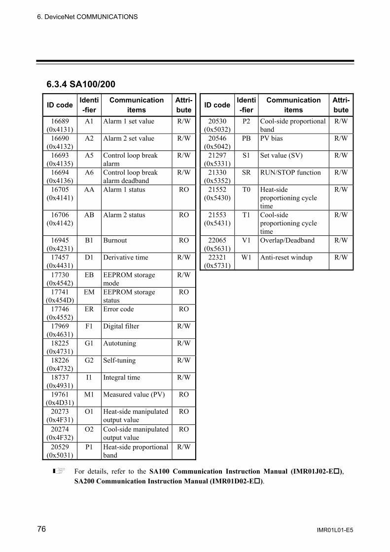
6. DeviceNet COMMUNICATIONS
IMR01L01-E5 76
6.3.4 SA100/200
ID code Identi-fier
Communication items
Attri-bute ID code Identi
-fierCommunication
items Attri-bute
16689 (0x4131)
A1 Alarm 1 set value R/W 20530 (0x5032)
P2 Cool-side proportional band
R/W
16690 (0x4132)
A2 Alarm 2 set value R/W 20546 (0x5042)
PB PV bias R/W
16693 (0x4135)
A5 Control loop break alarm
R/W 21297 (0x5331)
S1 Set value (SV) R/W
16694 (0x4136)
A6 Control loop break alarm deadband
R/W 21330 (0x5352)
SR RUN/STOP function R/W
16705 (0x4141)
AA Alarm 1 status RO 21552 (0x5430)
T0 Heat-side proportioning cycle time
R/W
16706 (0x4142)
AB Alarm 2 status RO 21553 (0x5431)
T1 Cool-side proportioning cycle time
R/W
16945 (0x4231)
B1 Burnout RO 22065 (0x5631)
V1 Overlap/Deadband R/W
17457 (0x4431)
D1 Derivative time R/W 22321 (0x5731)
W1 Anti-reset windup R/W
17730 (0x4542)
EB EEPROM storage mode
R/W
17741 (0x454D)
EM EEPROM storage status
RO
17746 (0x4552)
ER Error code RO
17969 (0x4631)
F1 Digital filter R/W
18225 (0x4731)
G1 Autotuning R/W
18226 (0x4732)
G2 Self-tuning R/W
18737 (0x4931)
I1 Integral time R/W
19761 (0x4D31)
M1 Measured value (PV) RO
20273 (0x4F31)
O1 Heat-side manipulated output value
RO
20274 (0x4F32)
O2 Cool-side manipulated output value
RO
20529 (0x5031)
P1 Heat-side proportional band
R/W
For details, refer to the SA100 Communication Instruction Manual (IMR01J02-E ), SA200 Communication Instruction Manual (IMR01D02-E ).

6. DeviceNet COMMUNICATIONS
IMR01L01-E5 77
6.3.5 MA900/901
ID code Identi-fier
Communication items
Attri-bute ID code Identi
-fierCommunication
items Attri-bute
16689 (0x4131)
A1 Alarm 1 set value R/W 18770 (0x4952)
IR Communication speed R/W
16690 (0x4132)
A2 Alarm 2 set value R/W 18772 (0x4954)
IT Interval time R/W
16691 (0x4133)
A3 Alarm 3 set value R/W 19505 (0x4C31)
L1 DI sutatus RO
16705 (0x4141)
AA Alarm 1 status RO 19531 (0x4C4B)
LK Lock level 1 R/W
16706 (0x4142)
AB Alarm 2 status RO 19532 (0x4C4C)
LL Lock level 2 R/W
16707 (0x4143)
AC Alarm 3 status RO 19761 (0x4D31)
M1 Measured value (PV) RO
16714 (0x414A)
AJ Output status RO 19762 (0x4D32)
M2 Current transformer 1 measured value
RO
16945 (0x4231)
B1 Burnout status RO 19763 (0x4D33)
M3 Current transformer 2 measured value
RO
17457 (0x4431)
D1 Derivative time R/W 19795 (0x4D53)
MS Set value monitor RO
17730 (0x4542)
EB EEPROM storage mode
R/W 20017 (0x4E31)
N1 Control loop break alarm deadband (LBD)
R/W
17737 (0x4549)
EI Used/unused of channel
R/W 20018 (0x4E32)
N2 Heater break alarm 2 (MA900 only)
R/W
17741 (0x454D)
EM EEPROM storage status
RO 20273 (0x4F31)
O1 Manipulated output value
RO
17746 (0x4552)
ER Error code RO
20274 (0x4F32)
O2 Cool-side manipulated output value (MA900 only)
RO
17969 (0x4631)
F1 Digital filter R/W 20529 (0x5031)
P1 Proportional band R/W
18225 (0x4731)
G1 PID/AT transfer R/W 20530 (0x5032)
P2 Cool-side Proportional band (MA900 only)
R/W
18504 (0x4848)
HH Setting change rate limiter
R/W 20546 (0x5042)
PB PV bias R/W
18737 (0x4931)
I1 Integral time R/W 21297 (0x5331)
S1 Set value (SV) R/W
18768 (0x4950)
IP Device address R/W 21330 (0x5352)
SR RUN/STOP transfer R/W
18769 (0x4951)
IQ Data bit configuration R/W 21552 (0x5430)
T0 Proportioning cycle time
R/W
Continued on the next page.
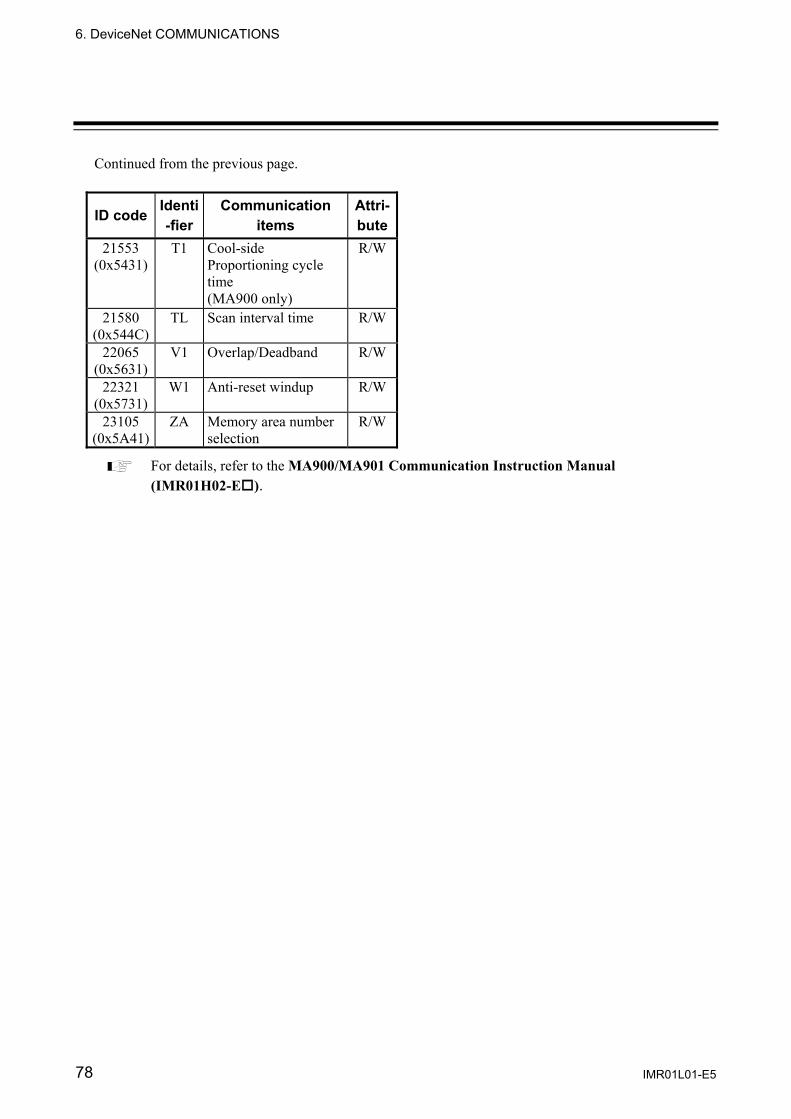
6. DeviceNet COMMUNICATIONS
IMR01L01-E5 78
Continued from the previous page.
ID code Identi-fier
Communication items
Attri-bute
21553 (0x5431)
T1 Cool-side Proportioning cycle time (MA900 only)
R/W
21580 (0x544C)
TL Scan interval time R/W
22065 (0x5631)
V1 Overlap/Deadband R/W
22321 (0x5731)
W1 Anti-reset windup R/W
23105 (0x5A41)
ZA Memory area number selection
R/W
For details, refer to the MA900/MA901 Communication Instruction Manual (IMR01H02-E ).
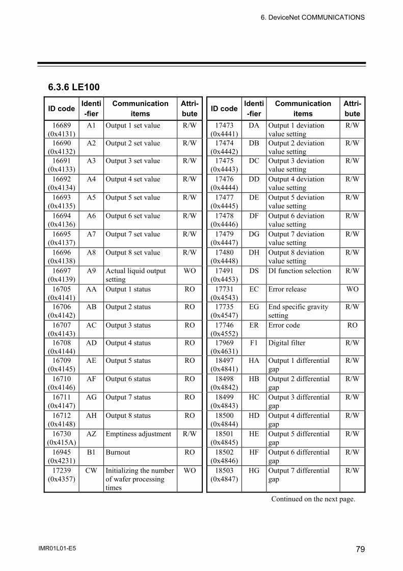
6. DeviceNet COMMUNICATIONS
IMR01L01-E5 79
6.3.6 LE100
ID code Identi-fier
Communication items
Attri-bute ID code Identi
-fierCommunication
items Attri-bute
16689 (0x4131)
A1 Output 1 set value R/W 17473 (0x4441)
DA Output 1 deviation value setting
R/W
16690 (0x4132)
A2 Output 2 set value R/W 17474 (0x4442)
DB Output 2 deviation value setting
R/W
16691 (0x4133)
A3 Output 3 set value R/W 17475 (0x4443)
DC Output 3 deviation value setting
R/W
16692 (0x4134)
A4 Output 4 set value R/W 17476 (0x4444)
DD Output 4 deviation value setting
R/W
16693 (0x4135)
A5 Output 5 set value R/W 17477 (0x4445)
DE Output 5 deviation value setting
R/W
16694 (0x4136)
A6 Output 6 set value R/W 17478 (0x4446)
DF Output 6 deviation value setting
R/W
16695 (0x4137)
A7 Output 7 set value R/W 17479 (0x4447)
DG Output 7 deviation value setting
R/W
16696 (0x4138)
A8 Output 8 set value R/W 17480 (0x4448)
DH Output 8 deviation value setting
R/W
16697 (0x4139)
A9 Actual liquid output setting
WO 17491 (0x4453)
DS DI function selection R/W
16705 (0x4141)
AA Output 1 status RO 17731 (0x4543)
EC Error release WO
16706 (0x4142)
AB Output 2 status RO 17735 (0x4547)
EG End specific gravity setting
R/W
16707 (0x4143)
AC Output 3 status RO 17746 (0x4552)
ER Error code RO
16708 (0x4144)
AD Output 4 status RO 17969 (0x4631)
F1 Digital filter R/W
16709 (0x4145)
AE Output 5 status RO 18497 (0x4841)
HA Output 1 differential gap
R/W
16710 (0x4146)
AF Output 6 status RO 18498 (0x4842)
HB Output 2 differential gap
R/W
16711 (0x4147)
AG Output 7 status RO 18499 (0x4843)
HC Output 3 differential gap
R/W
16712 (0x4148)
AH Output 8 status RO 18500 (0x4844)
HD Output 4 differential gap
R/W
16730 (0x415A)
AZ Emptiness adjustment R/W 18501 (0x4845)
HE Output 5 differential gap
R/W
16945 (0x4231)
B1 Burnout RO 18502 (0x4846)
HF Output 6 differential gap
R/W
17239 (0x4357)
CW Initializing the number of wafer processing times
WO 18503 (0x4847)
HG Output 7 differential gap
R/W
Continued on the next page.

6. DeviceNet COMMUNICATIONS
IMR01L01-E5 80
Continued from the previous page.
ID code Identi-fier
Communication items
Attri-bute ID code Identi
-fierCommunication
items Attri-bute
18504 (0x4848)
HH Output 8 differential gap
R/W 19512 (0x4C38)
L8 Linearizing table setting 8
R/W
18512 (0x4850)
HP Peak hold monitor RO 19513 (0x4C39)
L9 Linearizing table setting 9
R/W
18513 (0x4851)
HQ Bottom hold monitor RO 19521 (0x4C41)
LA Linearizing table setting 10
R/W
18514 (0x4852)
HR Hold reset WO 19540 (0x4C54)
LT Number of linearizing table setting
R/W
18518 (0x4856)
HV Monitor output high R/W 19541 (0x4C55)
LU Decimal point position selection
R/W
18519 (0x4857)
HW Monitor output high R/W 19761 (0x4D31)
M1 Measured value (PV) RO
18770 (0x4952)
IR Interlock release WO 19788 (0x4D4C)
ML Scale low monitor RO
18771 (0x4953)
IS Default setting WO 19784 (0x4D48)
MH Scale high monitor RO
18993 (0x4A31)
J1 Scale 1 actual liquid setting
R/W 19789 (0x4D4D)
MM Volume/level display selection
R/W
18994 (0x4A32)
J2 Scale 2 actual liquid setting
R/W 19799 (0x4D57)
MW Number of wafer processing times monitor
RO
18995 (0x4A33)
J3 Correction on the low limit side by actual liquid 2
WO 19802 (0x4D5A)
MZ Amount of emptiness correction monitor
RO
18996 (0x4A34)
J4 Correction on the high limit side by actual liquid 2
WO 20033 (0x4E41)
NA Output 1 a/b contact selection
R/W
19504 (0x4C30)
L0 Linearizing table setting 0
R/W 20034 (0x4E42)
NB Output 2 a/b contact selection
R/W
19505 (0x4C31)
L1 Linearizing table setting 1
R/W 20035 (0x4E43)
NC Output 3 a/b contact selection
R/W
19506 (0x4C32)
L2 Linearizing table setting 2
R/W 20036 (0x4E44)
ND Output 4 a/b contact selection
R/W
19507 (0x4C33)
L3 Linearizing table setting 3
R/W 20037 (0x4E45)
NE Output 5 a/b contact selection
R/W
19508 (0x4C34)
L4 Linearizing table setting 4
R/W 20038 (0x4E46)
NF Output 6 a/b contact selection
R/W
19509 (0x4C35)
L5 Linearizing table setting 5
R/W 20039 (0x4E47)
NG Output 7 a/b contact selection
R/W
19510 (0x4C36)
L6 Linearizing table setting 6
R/W 20040 (0x4E48)
NH Output 8 a/b contact selection
R/W
19511 (0x4C37)
L7 Linearizing table setting 7
R/W 20801 (0x5141)
QA Output 1 interlocking function selection
R/W
Continued on the next page.

6. DeviceNet COMMUNICATIONS
IMR01L01-E5 81
Continued from the previous page.
ID code Identi-fier
Communication items
Attri-bute ID code Identi
-fierCommunication
items Attri-bute
20802 (0x5142)
QB Output 2 interlocking function selection
R/W 22356 (0x5754)
WT Number of wafer processing times
WO
20803 (0x5143)
QC Output 3 interlocking function selection
R/W 22593 (0x5841)
XA Output 1 type selection R/W
20804 (0x5144)
QD Output 4 interlocking function selection
R/W 22594 (0x5842)
XB Output 2 type selection R/W
20805 (0x5145)
QE Output 5 interlocking function selection
R/W 22595 (0x5843)
XC Output 3 type selection R/W
20806 (0x5146)
QF Output 6 interlocking function selection
R/W 22596 (0x5844)
XD Output 4 type selection R/W
20807 (0x5147)
QG Output 7 interlocking function selection
R/W 22597 (0x5845)
XE Output 5 type selection R/W
20808 (0x5148)
QH Output 8 interlocking function selection
R/W 22598 (0x5846)
XF Output 6 type selection R/W
21319 (0x5347)
SG Specific gravity setting R/W 22599 (0x5847)
XG Output 7 type selection R/W
21328 (0x5350)
SP Specific gravity setting transfer
R/W 22600 (0x5848)
XH Output 8 type selection R/W
21331 (0x5353)
SS Specific gravity correction function selection
R/W 22616 (0x5858)
XX Scale low R/W
21335 (0x5357)
SW Number of wafer processing times setting
R/W
21569 (0x5441)
TA Output 1 timer setting R/W
21570 (0x5442)
TB Output 2 timer setting R/W
21571 (0x5443)
TC Output 3 timer setting R/W
21572 (0x5444)
TD Output 4 timer setting R/W
21573 (0x5445)
TE Output 5 timer setting R/W
21574 (0x5446)
TF Output 6 timer setting R/W
21575 (0x5447)
TG Output 7 timer setting R/W
21576 (0x5448)
TH Output 8 timer setting R/W
21838 (0x554E)
UN Unit setting R/W
For details, refer to the LE100 Communication Instruction Manual (IMR01C02-E ).

6. DeviceNet COMMUNICATIONS
IMR01L01-E5 82
6.3.7 REX-PG410
ID code Identi-fier
Communication items
Attri-bute ID code Identi
-fierCommunication
items Attri-bute
16689 (0x4131)
A1 First alarm setting R/W 20034 (0x4E42)
NB Second alarm Energized/ De-energized
R/W
16690 (0x4132)
A2 Second alarm setting R/W 20565 (0x5055)
PU Pressure unit setting R/W
16705 (0x4141)
AA First alarm monitor RO 20801 (0x5141)
QA First alarm interlock function
R/W
16706 (0x4142)
AB Second alarm monitor RO 20802 (0x5142)
QB Second alarm interlock function
R/W
16730 (0x415A)
AZ Auto-zero R/W 21572 (0x5444)
TD First alarm timer setting
R/W
16945 (0x4231)
B1 Burnout RO 21575 (0x5447)
TG Second alarm timer setting
R/W
17746 (0x4552)
ER Error data RO 21580 (0x544C)
TL Display timer setting R/W
18241 (0x4741)
GA Gain setting R/W 21583 (0x544F)
TO Analog output timer setting
R/W
18497 (0x4841)
HA First alarm differential gap
R/W 22593 (0x5841)
XA First alarm action selection
R/W
18498 (0x4842)
HB Second alarm differential gap
R/W 22594 (0x5842)
XB Second alarm action selection
R/W
18512 (0x4850)
HP Peak hold monitor RO
22601 (0x5849)
XI Input type selection R/W
18513 (0x4851)
HQ Bottom hold monitor RO
22613 (0x5855)
XU Decimal point positionselection
R/W
18514 (0x4852)
HR Hold reset WO 22614 (0x5856)
XW Low-limit setting of pressure display
R/W
18518 (0x4856)
HV High-limit setting of analog output
R/W 22615 (0x5857)
XV High-limit setting of pressure display
R/W
18519 (0x4857)
HW Low-limit setting of analog output
R/W
18754 (0x4942)
IB Action of input break selection
R/W
18770 (0x4952)
IR Alarm interlock release
WO
19529 (0x4C49)
LI Linearize type selection
R/W
19761 (0x4D31)
M1 Measured value (PV) RO
20033 (0x4E41)
NA First alarm Energized/ De-energized
R/W
For details, refer to the REX-PG410 Communication Instruction Manual (IM41PG02-E ).
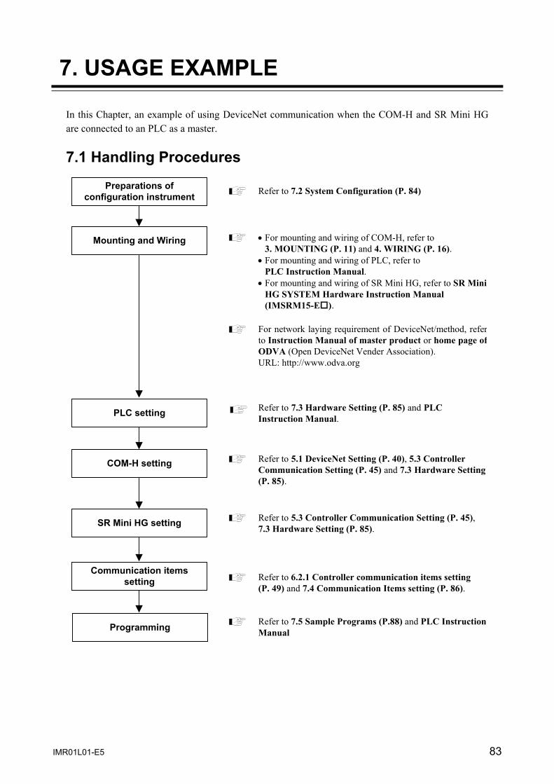
IMR01L01-E5 83
7. USAGE EXAMPLE
In this Chapter, an example of using DeviceNet communication when the COM-H and SR Mini HG are connected to an PLC as a master. 7.1 Handling Procedures
Preparations of configuration instrument
Mounting and Wiring
PLC setting
COM-H setting
SR Mini HG setting
Communication items setting
Programming
Refer to 7.2 System Configuration (P. 84)
• For mounting and wiring of COM-H, refer to 3. MOUNTING (P. 11) and 4. WIRING (P. 16). • For mounting and wiring of PLC, refer to PLC Instruction Manual. • For mounting and wiring of SR Mini HG, refer to SR Mini HG SYSTEM Hardware Instruction Manual (IMSRM15-E ).
For network laying requirement of DeviceNet/method, refer to Instruction Manual of master product or home page of ODVA (Open DeviceNet Vender Association). URL: http://www.odva.org
Refer to 7.3 Hardware Setting (P. 85) and PLC Instruction Manual.
Refer to 5.1 DeviceNet Setting (P. 40), 5.3 Controller Communication Setting (P. 45) and 7.3 Hardware Setting(P. 85).
Refer to 5.3 Controller Communication Setting (P. 45),7.3 Hardware Setting (P. 85).
Refer to 6.2.1 Controller communication items setting (P. 49) and 7.4 Communication Items setting (P. 86).
Refer to 7.5 Sample Programs (P.88) and PLC Instruction Manual

7. USAGE EXAMPLE
84 IMR01L01-E5
7.2 System Configuration
Fig. 7-1 Example of system configurations Use instruments
• DeviceNet communication converter COM-H-3-90-1-N
• SR Mini HG SYSTEM Power/CPU module H-PCP-A, Temperature control module H-TIO-A, Current transformer input module H-CT-A, Analog input module H-AI-B
• PLC - SYSMAC CS1 (OMRON product)
CPU unit: CS1G-CPU44, DeviceNet master unit: C200HW-DRM21-V1 or
- Control Logix 5550 [Rockwell Inc. (Allen-Bradley)] CPU module: 1756-L1, LINK module (DeviceNet): 1756-DNB
PLC (Master)
DeviceNet communication converter COM-H (Slave)
DeviceNet
RS-422A
H-CT-A H-AI-BH-TIO-AH-PCP-A
SR Mini HG control unit

7. USAGE EXAMPLE
IMR01L01-E5 85
7.3 Hardware Setting Set each hardware’s as the following. PLC setting
Set PLC in requirement of the following.
[DeviceNet communication requirement] • Node address: 0 • DeviceNet communication speed: 125 kbps • Unit Number: 0
For setting method, refer to Instruction Manual for PLC. COM-H setting
Set COM-H in requirement of the following.
[DeviceNet communication requirement] • Node address: 1 • DeviceNet communication speed: 125 kbps • Connection controller model: SR Mini HG • Communication mode: Communication model A (Compatible mode) or
Communication model B (Expansion mode)
[SR Mini HG communication requirement] • SR Mini HG communication speed: 9600 bps • SR Mini HG data bit configuration: Data 8 bits, Without parity, Stop 1 bit
For setting method, refer to 5.1 DeviceNet Setting (P. 40), 5.2 Connection Controller and Communication mode setting (P.42) and 5.3 Controller Communication Setting (P. 45).
SR Mini HG setting
Set SR Mini HG in requirement of the following.
[SR Mini HG communication requirement] • SR Mini HG address: 0 • SR Mini HG communication speed: 9600 bps • SR Mini HG data bit configuration: Data 8 bits, Without parity, Stop 1 bit
For setting method, refer to 5.3 Controller Communication Setting (P. 45) and SR Mini HG Communication Instruction Manual (IMSRM09-E ).
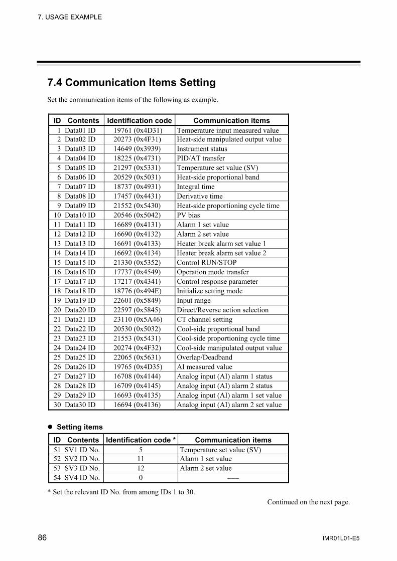
7. USAGE EXAMPLE
86 IMR01L01-E5
7.4 Communication Items Setting Set the communication items of the following as example.
ID Contents Identification code Communication items1 Data01 ID 19761 (0x4D31) Temperature input measured value 2 Data02 ID 20273 (0x4F31) Heat-side manipulated output value 3 Data03 ID 14649 (0x3939) Instrument status 4 Data04 ID 18225 (0x4731) PID/AT transfer 5 Data05 ID 21297 (0x5331) Temperature set value (SV) 6 Data06 ID 20529 (0x5031) Heat-side proportional band 7 Data07 ID 18737 (0x4931) Integral time 8 Data08 ID 17457 (0x4431) Derivative time 9 Data09 ID 21552 (0x5430) Heat-side proportioning cycle time
10 Data10 ID 20546 (0x5042) PV bias 11 Data11 ID 16689 (0x4131) Alarm 1 set value 12 Data12 ID 16690 (0x4132) Alarm 2 set value 13 Data13 ID 16691 (0x4133) Heater break alarm set value 1 14 Data14 ID 16692 (0x4134) Heater break alarm set value 2 15 Data15 ID 21330 (0x5352) Control RUN/STOP 16 Data16 ID 17737 (0x4549) Operation mode transfer 17 Data17 ID 17217 (0x4341) Control response parameter 18 Data18 ID 18776 (0x494E) Initialize setting mode 19 Data19 ID 22601 (0x5849) Input range 20 Data20 ID 22597 (0x5845) Direct/Reverse action selection 21 Data21 ID 23110 (0x5A46) CT channel setting 22 Data22 ID 20530 (0x5032) Cool-side proportional band 23 Data23 ID 21553 (0x5431) Cool-side proportioning cycle time 24 Data24 ID 20274 (0x4F32) Cool-side manipulated output value 25 Data25 ID 22065 (0x5631) Overlap/Deadband 26 Data26 ID 19765 (0x4D35) AI measured value 27 Data27 ID 16708 (0x4144) Analog input (AI) alarm 1 status 28 Data28 ID 16709 (0x4145) Analog input (AI) alarm 2 status 29 Data29 ID 16693 (0x4135) Analog input (AI) alarm 1 set value 30 Data30 ID 16694 (0x4136) Analog input (AI) alarm 2 set value
Setting items
ID Contents Identification code * Communication items51 SV1 ID No. 5 Temperature set value (SV) 52 SV2 ID No. 11 Alarm 1 set value 53 SV3 ID No. 12 Alarm 2 set value 54 SV4 ID No. 0 −−−
* Set the relevant ID No. from among IDs 1 to 30. Continued on the next page.
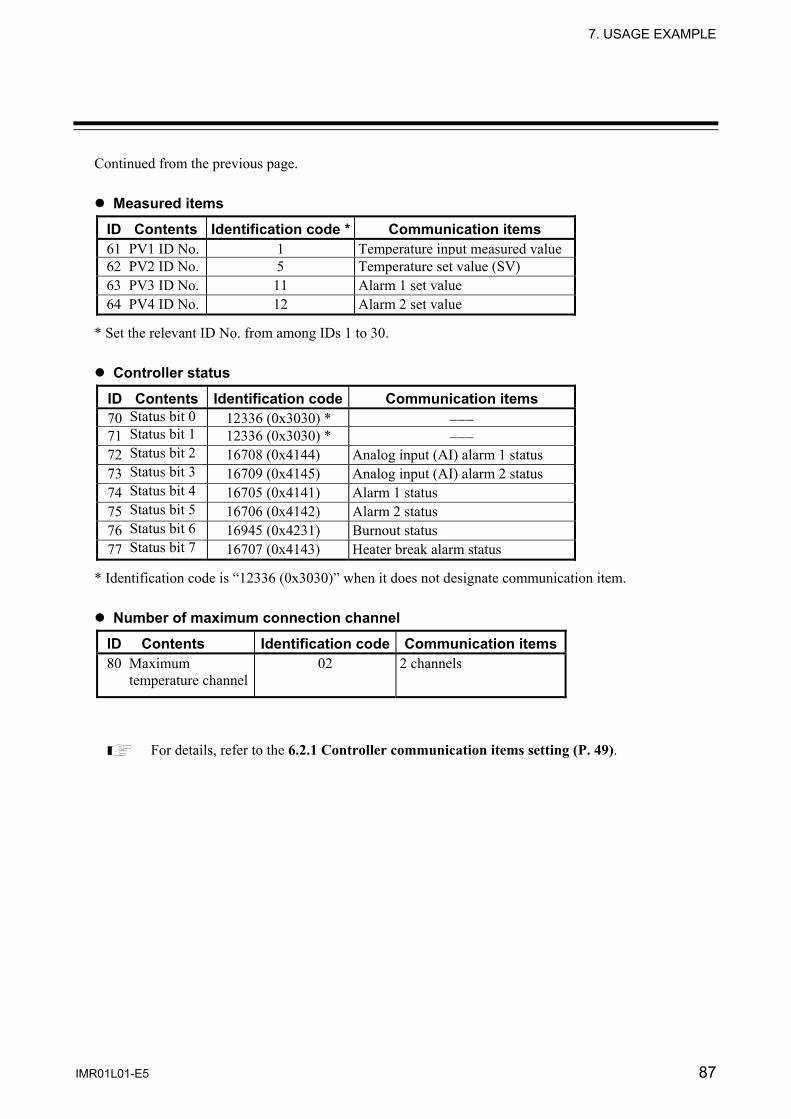
7. USAGE EXAMPLE
IMR01L01-E5 87
Continued from the previous page. Measured items
ID Contents Identification code * Communication items61 PV1 ID No. 1 Temperature input measured value 62 PV2 ID No. 5 Temperature set value (SV) 63 PV3 ID No. 11 Alarm 1 set value 64 PV4 ID No. 12 Alarm 2 set value
* Set the relevant ID No. from among IDs 1 to 30. Controller status
ID Contents Identification code Communication items70 Status bit 0 12336 (0x3030) * −−−71 Status bit 1 12336 (0x3030) * −−− 72 Status bit 2 16708 (0x4144) Analog input (AI) alarm 1 status 73 Status bit 3 16709 (0x4145) Analog input (AI) alarm 2 status 74 Status bit 4 16705 (0x4141) Alarm 1 status 75 Status bit 5 16706 (0x4142) Alarm 2 status 76 Status bit 6 16945 (0x4231) Burnout status 77 Status bit 7 16707 (0x4143) Heater break alarm status
* Identification code is “12336 (0x3030)” when it does not designate communication item. Number of maximum connection channel
ID Contents Identification code Communication items80 Maximum
temperature channel 02 2 channels
For details, refer to the 6.2.1 Controller communication items setting (P. 49).

7. USAGE EXAMPLE
88 IMR01L01-E5
7.5 Sample Programs 7.5.1 Polling I/O communication (When the SYSMAC CS1)
Polling I/O communication is called “Remote I/O communication” in OMRON PLC related instruction manuals.
Communication requirement
The data type (temperature input data), channel number (1 or 2) and set value are sent from the SYSMAC CS1, and temperature input measured values corresponding to temperature control channels 1 and 2 are read from the COM-H.
Communication mode setting • Communication mode A (Compatible mode) Data to send from a PLC • Temperature control channel 1 set value: 100 • Temperature control channel 2 set value: 100 Storage location of read data • Temperature control channel 1 measured value: D00001 • Temperature control channel 2 measured value: D00002 Memory allocation
Default allocations (without Configuration) • SYSMAC CS1 I/O allocation
Output area: IR0050 to IR0099 Input area: IR0350 to IR0399
• COM-H (Node address 1) I/O allocation Output area: IR0051, IR0052 Input area: IR0351, IR0352
Output area
Node address Input area
IR0050 0 IR0350 IR0051 1 IR0351 IR0052 2 IR0352 IR0053 3 IR0353 IR0054 4 IR0354
Fig. 7-2 Memory allocation
Continued on the next page.
: COM-H allocation area
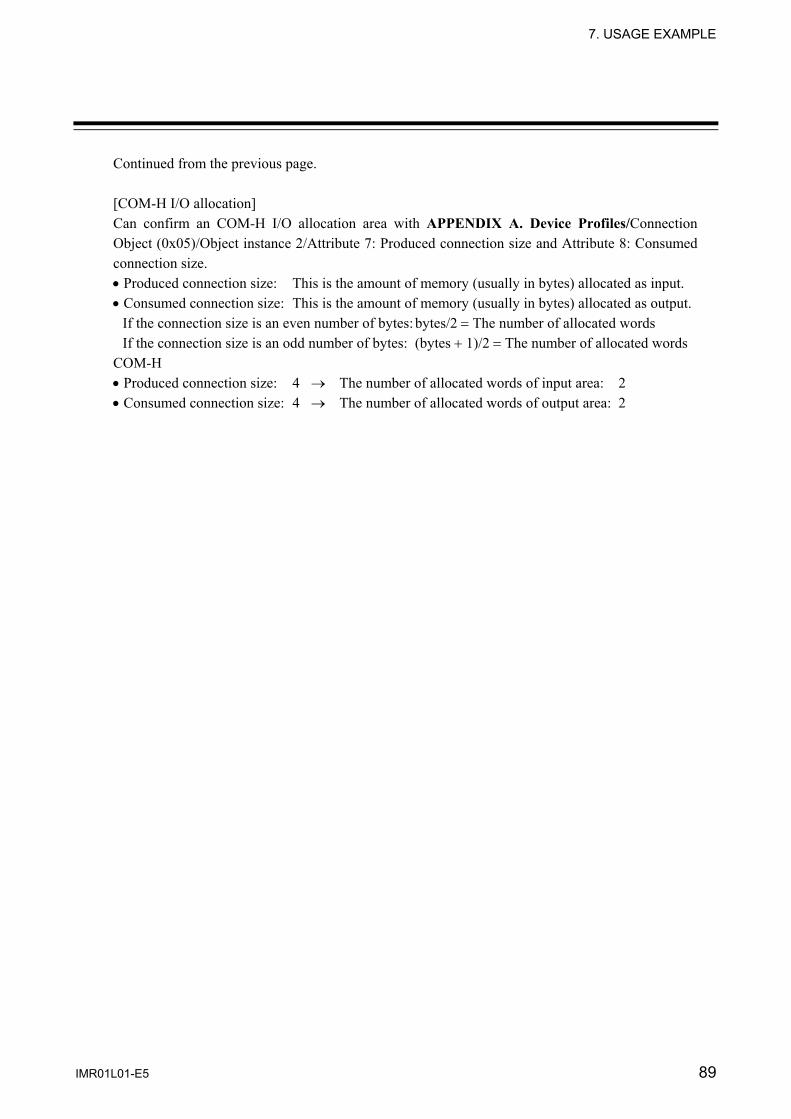
7. USAGE EXAMPLE
IMR01L01-E5 89
Continued from the previous page. [COM-H I/O allocation] Can confirm an COM-H I/O allocation area with APPENDIX A. Device Profiles/Connection Object (0x05)/Object instance 2/Attribute 7: Produced connection size and Attribute 8: Consumed connection size. • Produced connection size: This is the amount of memory (usually in bytes) allocated as input. • Consumed connection size: This is the amount of memory (usually in bytes) allocated as output.
If the connection size is an even number of bytes: bytes/2 = The number of allocated words If the connection size is an odd number of bytes: (bytes + 1)/2 = The number of allocated words
COM-H • Produced connection size: 4 → The number of allocated words of input area: 2 • Consumed connection size: 4 → The number of allocated words of output area: 2
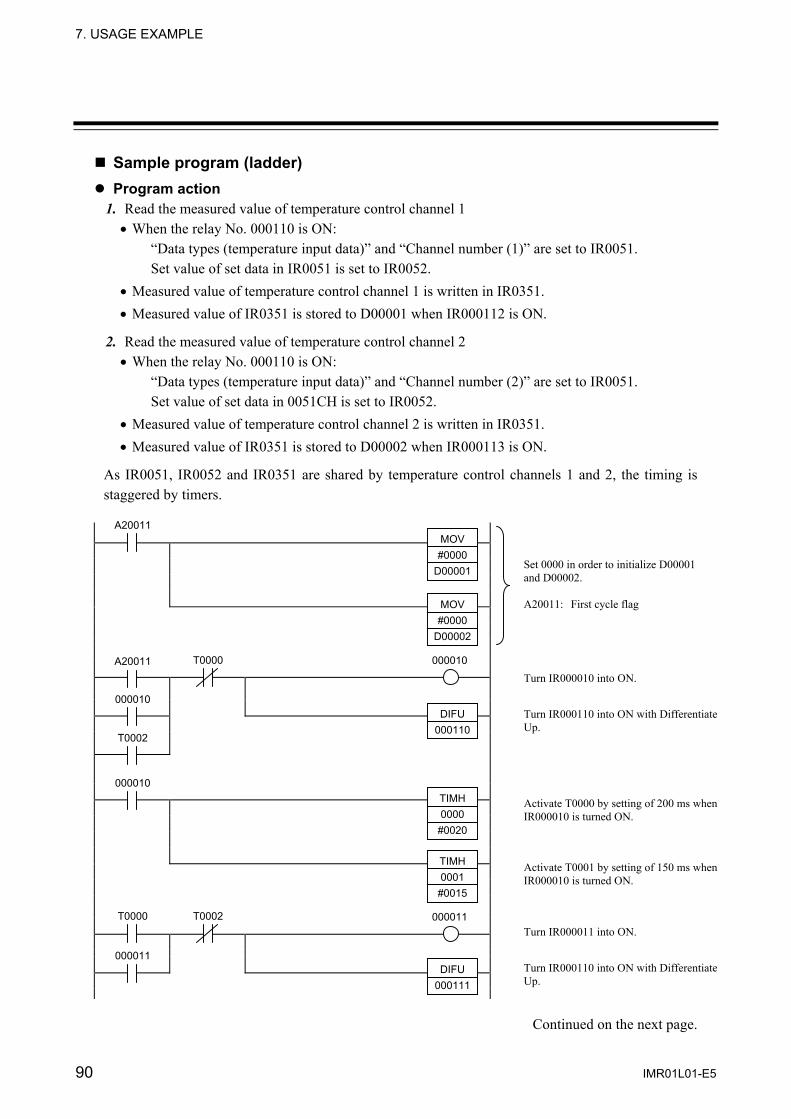
7. USAGE EXAMPLE
90 IMR01L01-E5
Sample program (ladder) Program action 1. Read the measured value of temperature control channel 1
• When the relay No. 000110 is ON: “Data types (temperature input data)” and “Channel number (1)” are set to IR0051. Set value of set data in IR0051 is set to IR0052.
• Measured value of temperature control channel 1 is written in IR0351. • Measured value of IR0351 is stored to D00001 when IR000112 is ON.
2. Read the measured value of temperature control channel 2 • When the relay No. 000110 is ON:
“Data types (temperature input data)” and “Channel number (2)” are set to IR0051. Set value of set data in 0051CH is set to IR0052.
• Measured value of temperature control channel 2 is written in IR0351. • Measured value of IR0351 is stored to D00002 when IR000113 is ON.
As IR0051, IR0052 and IR0351 are shared by temperature control channels 1 and 2, the timing is staggered by timers.
Continued on the next page.
MOV #0000
D00001
A20011
000010
Set 0000 in order to initialize D00001 and D00002. A20011: First cycle flag
Turn IR000010 into ON.
Turn IR000110 into ON with Differentiate Up.
Activate T0000 by setting of 200 ms when IR000010 is turned ON.
Activate T0001 by setting of 150 ms when IR000010 is turned ON.
MOV #0000
D00002
A20011 T0000
000010
T0002
DIFU 000110
000010 TIMH 0000
#0020
TIMH 0001
#0015
T0000 000011Turn IR000011 into ON.
000011 Turn IR000110 into ON with Differentiate Up.
T0002
DIFU 000111

7. USAGE EXAMPLE
IMR01L01-E5 91
Continued from the previous page.
Set “Data types (temperature input data: 1)” and “Channel number (1)” in IR0051.
Set “Data types (temperature input data: 1)” and “Channel number (2)” in IR0051.
Set “Set value (100 = 64H)” in IR0052.
Set “Set value (100 = 64H)” in IR0052.
#0101
Channel number Data type
000011 Activate T0002 by setting of 200 ms when IR000011 is turned ON.
Activate T0003 by setting of 150 ms when IR000011 is turned ON.
Temperature control channel 1 “Measured value” of IR0351 is stored in D00001 when IR000112 is turned ON.
Temperature control channel 2 “Measured value” of IR0351 is stored in D00002 when IR000113 is turned ON.
TIMH 0002
#0020
TIMH 0003
#0015
END
000110 MOV #01010051
MOV #00640052
000111 MOV #02010051
MOV #00640052
T0001 DIFU
000112
Turn IR000112 into ON with Differentiate Up when T0001 is turned ON.
Turn IR000113 into ON with Differentiate Up when T0003 is turned ON.
000112 MOV 0351
D00001
T0003 DIFU
000113
000113 MOV 0351
D00002

7. USAGE EXAMPLE
92 IMR01L01-E5
7.5.2 Polling I/O communication (When the Control Logix 5550) Communication requirement
The data type (temperature input data), channel number (1 or 2) and set value are sent from the “Rockwell (Allen-Bradley) Control Logix 5550,” and temperature input measured values corresponding to temperature control channels 1 and 2 are read from the “COM-H.” Communication mode setting • Communication mode B (Expansion mode) Data to send from a PLC Send the following three items sequentially. • Temperature set value (Data type = 1: ID5) • Alarm 1 set value (Data type = 2: ID11) • Alarm 2 set value (Data type = 3: ID12)
Data to send from a COM-H • Temperature input measured value (ID1) • Temperature set value (ID5) • Alarm 1 set value (ID11) • Alarm 2 set value (ID12) • Controller status
In case of the temperature controller, set value does poling as monitor data.
Program action As action of sequence program, there are monitor mode and setting mode. Execute the mode transfer with display unit connected to PLC.
<Monitor mode> In case of monitor mode, set value does not send from PLC when set data type in “0.” Only read of the measured value from the controller.
• Storage location of read data (Variable) - Temperature control channel 1 measured value: N20[1] - Temperature control channel 2 measured value: N20[2] - Temperature control channel 1 set value: N20[11] - Temperature control channel 2 set value: N20[12] - Temperature control channel 1 alarm 1 set value: N20[21] - Temperature control channel 2 alarm 1 set value: N20[22] - Temperature control channel 1 alarm 2 set value: N20[31] - Temperature control channel 2 alarm 2 set value: N20[32] - Temperature control channel 1 status: N20[41] - Temperature control channel 2 status: N20[42]
Continued on the next page.
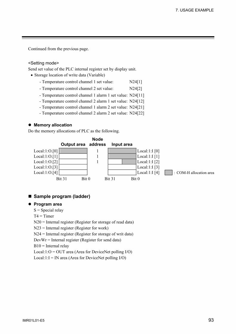
7. USAGE EXAMPLE
IMR01L01-E5 93
Continued from the previous page.
<Setting mode> Send set value of the PLC internal register set by display unit.
• Storage location of write data (Variable) - Temperature control channel 1 set value: N24[1] - Temperature control channel 2 set value: N24[2] - Temperature control channel 1 alarm 1 set value: N24[11] - Temperature control channel 2 alarm 1 set value: N24[12] - Temperature control channel 1 alarm 2 set value: N24[21] - Temperature control channel 2 alarm 2 set value: N24[22]
Memory allocation
Do the memory allocations of PLC as the following.
Output area
Node address Input area
Local:1:O.[0] 1 Local:1:I [0]Local:1:O.[1] 1 Local:1:I [1]Local:1:O.[2] 1 Local:1:I [2]Local:1:O.[3] Local:1:I [3]Local:1:O.[4] Local:1:I [4]
Bit 31 Bit 0 Bit 31 Bit 0 Sample program (ladder) Program area
S = Special relay T4 = Timer N20 = Internal register (Register for storage of read data) N23 = Internal register (Register for work) N24 = Internal register (Register for storage of writ data) DevWr = Internal register (Register for send data) B10 = Internal relay Local:1:O = OUT area (Area for DeviceNet polling I/O) Local:1:I = IN area (Area for DeviceNet polling I/O)
: COM-H allocation area
7. USAGE EXAMPLE
94 IMR01L01-E5
Program action 1. When data read of the temperature control channel 1
• With monitor mode (MODE[0]=OFF) in case of internal relay (B10[0]) ON Sets “data type: 0” and “channel number: 1” to “Local:1:O.Data[0].” Data of temperature control channel 1 is written in at I/O area.
Local:1:I.Data[0]: low-order data: Measured value
High-order data: Set value Local:1:I.Data[1]:
low-order data: Alarm 1 set value High-order data: Alarm 2 set value
Local:1:I.Data[2]: low-order data: Instrument status
• With time-up of “T4[0],” saved data of “Local:1:I.Data [0 to 2]” in each storage areas.
2. When writes in set value of the temperature control channel 2 • With setting mode (MODE[0]=ON) in case of internal relay (B10[0]) ON Sets “data type: 5,” “channel number: 2” and set value to “Local:1:O.Data[0].”
As “Local:1:O” and “Local:1:I” are shared by temperature control channels 1 and 2, the timing is staggered by timers.
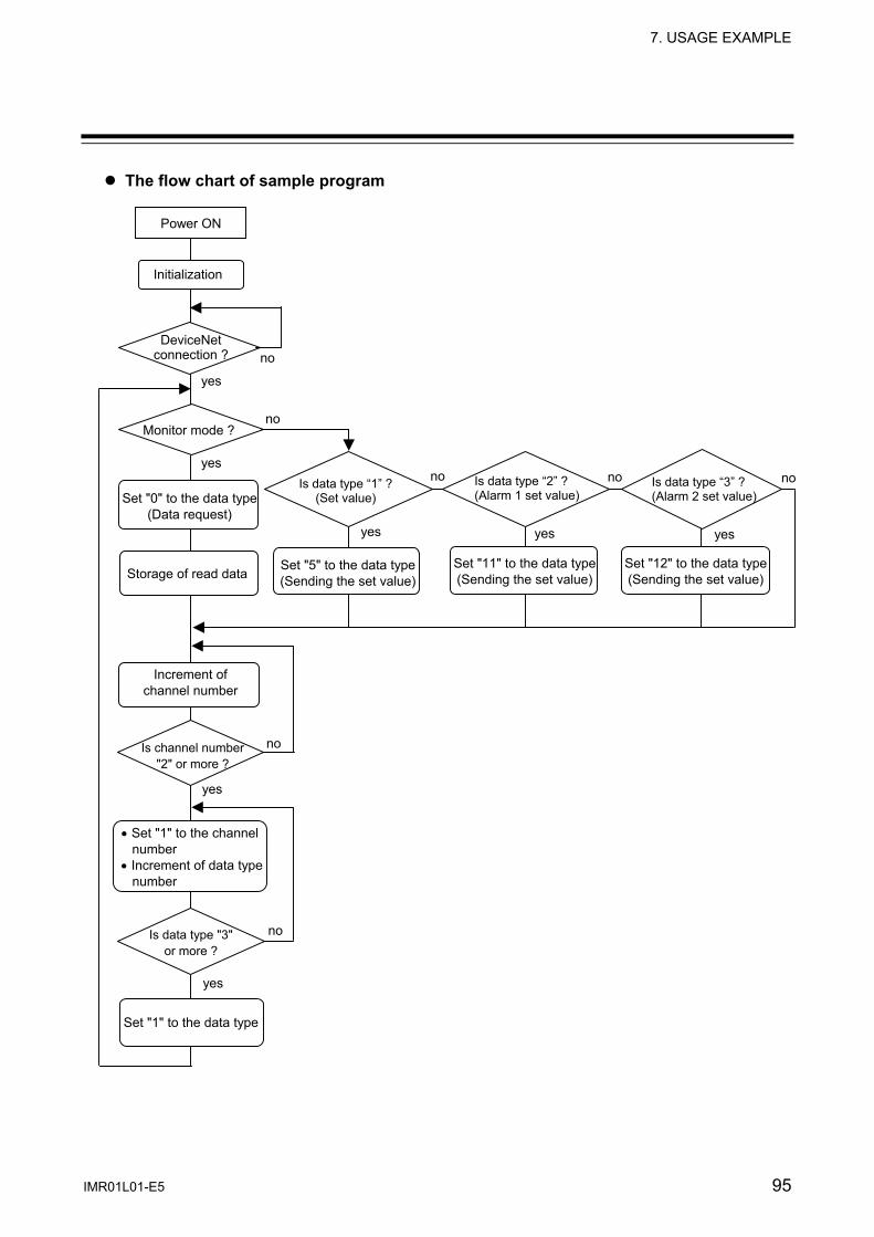
7. USAGE EXAMPLE
IMR01L01-E5 95
The flow chart of sample program
Power ON
Initialization
DeviceNet connection ?
yes
Monitor mode ?
yes
Set "0" to the data type(Data request)
Storage of read data
Increment of channel number
Is channel number "2" or more ?
• Set "1" to the channel number
• Increment of data type number
Is data type "3" or more ?
Set "1" to the data type
yes
Set "5" to the data type(Sending the set value)
Is data type “2” ?(Alarm 1 set value)
Is data type “3” ?(Alarm 2 set value)
Is data type “1” ?(Set value)
yes
yes yes yes
no
no
no no no
no
no
Set "11" to the data type(Sending the set value)
Set "12" to the data type(Sending the set value)

7. USAGE EXAMPLE
96 IMR01L01-E5
Continued on the next page.
Turns “Local:1:O.Comand Register .Run” of OUT area into ON, and starts DeviceNet.
Writes in “0” at “S24” (chNo.) and ”N23[10]」” (data type) at start-up, and initializes it. Clears mode, and changes it into monitor mode.
• S:FS = Is ON only one-scan at start-up.
The internal relay, “B10[0]” is self-held at the time of start-up or when the timer, “T40[0]” is time-up (processing end of each channel). The hold-relay reset is done in time-up of timer “T4[0].”
While “B10[0]” is being held, a time of 100 ms is counted by the timer, “T4[0].”
Confirm that slave was connected to DeviceNet with “Local:1:I.StatusRegister.DeviceFailure.” Start I/O polling processing from the connection one second later.
If “N24[11]” (data type No.) is set to “1,” set “5” which is the set value data type ID No. to “N24[10]” (data type setting register). Set the set value stored in “N24[chNo.]” to “N23[15]” (set value setting register).
If “N24[11]” (data type No.) is set to “2,” set “11” which is the alarm 1 set value data type ID No. to “N24[10]” (data type setting register). Set the alarm 1 set value stored in “N24[chNo.]” to “N23[15]” (set value setting register).
If “N24[11]” (data type No.) is set to “3,” set “12” which is the alarm 1 set value data type ID No. to “N24[10]” (data type setting register). Set the alarm 2 set value stored in “N24[chNo.]” to “N23[15]” (set value setting register).
When changing the set mode to the monitor mode, set the one-second-delay timer. • It takes about one second to transmit all the set value of tow channel.
When at “T4:[2]” = ON (DeviceNet connection) and “T4:[3]” = OFF (monitor mode), the set value, alarm 1 set value and alarm 2 set value read from the slave are copied to the storage area used for data write.
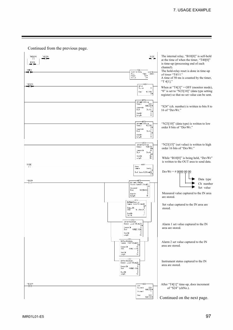
7. USAGE EXAMPLE
IMR01L01-E5 97
Continued from the previous page.
Continued on the next page.
A time of 50 ms is counted by the timer, “T 4[1].”
DevWr = # 0000 00 00
Data type Ch number Set value
Measured value captured to the IN area are stored.
After “T4[1]” time-up, does increment of “S24” (chNo.).
When at “T4[3]” = OFF (monitor mode), “0” is set to “N23[10]” (data type setting register) so that no set value can be sent.
The internal relay, “B10[0]” is self-held at the time of when the timer, “T40[0]” is time-up (processing end of each channel). The hold-relay reset is done in time-up of timer “T4[1].”
“S24” (ch. number) is written to bits 8 to 16 of “DevWr.”
“N23[10]” (data type) is written to low order 8 bits of “DevWr.”
“N23[15]” (set value) is written to high order 16 bits of “DevWr.”
Set value captured to the IN area are stored.
Alarm 1 set value captured to the IN area are stored.
Alarm 2 set value captured to the IN area are stored.
Instrument status captured to the IN area are stored.
While “B10[0]” is being held, “DevWr”is written to the OUT area to send data.

7. USAGE EXAMPLE
98 IMR01L01-E5
Continued from the previous page.
If at more than “2” as a result of incrementing “S24” (chNo.), set “S24” to “1” to be set to channel 1. Also increment “N23[11]” (data type No.).
If at more than “3” as a result of incrementing “N23[11],” set “N23[11]”to “1” to set the data type to the set value.
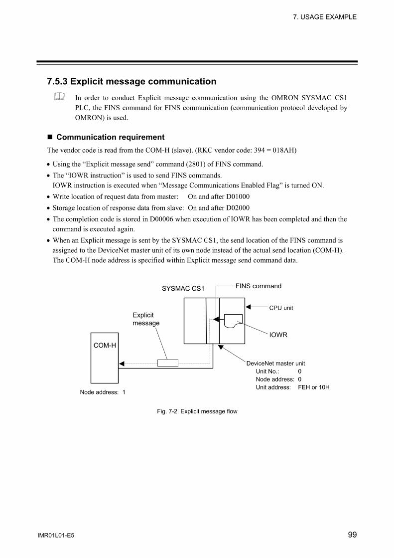
7. USAGE EXAMPLE
IMR01L01-E5 99
7.5.3 Explicit message communication In order to conduct Explicit message communication using the OMRON SYSMAC CS1 PLC, the FINS command for FINS communication (communication protocol developed by OMRON) is used.
Communication requirement
The vendor code is read from the COM-H (slave). (RKC vendor code: 394 = 018AH)
• Using the “Explicit message send” command (2801) of FINS command. • The “IOWR instruction” is used to send FINS commands.
IOWR instruction is executed when “Message Communications Enabled Flag” is turned ON. • Write location of request data from master: On and after D01000 • Storage location of response data from slave: On and after D02000 • The completion code is stored in D00006 when execution of IOWR has been completed and then the
command is executed again. • When an Explicit message is sent by the SYSMAC CS1, the send location of the FINS command is
assigned to the DeviceNet master unit of its own node instead of the actual send location (COM-H). The COM-H node address is specified within Explicit message send command data.
Fig. 7-2 Explicit message flow
FINS command
IOWR
CPU unit
DeviceNet master unit Unit No.: 0 Node address: 0 Unit address: FEH or 10H
SYSMAC CS1
Explicit message
COM-H
Node address: 1
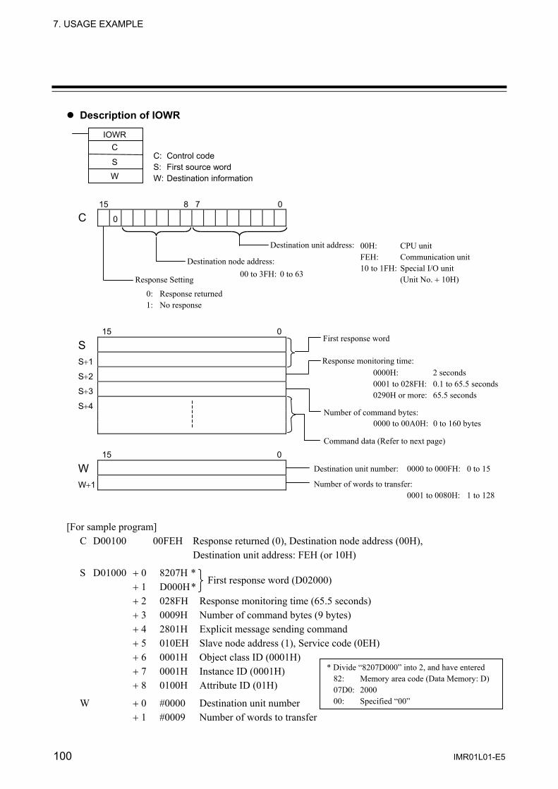
7. USAGE EXAMPLE
100 IMR01L01-E5
Description of IOWR
15 8 7 0
C 0
15 0
S
S+1
S+2
S+3
S+4
15 0
W
W+1
[For sample program]
C D00100 00FEH Response returned (0), Destination node address (00H), Destination unit address: FEH (or 10H)
S D01000 + 0 8207H * + 1 D000H* + 2 028FH Response monitoring time (65.5 seconds) + 3 0009H Number of command bytes (9 bytes) + 4 2801H Explicit message sending command + 5 010EH Slave node address (1), Service code (0EH) + 6 0001H Object class ID (0001H) + 7 0001H Instance ID (0001H) + 8 0100H Attribute ID (01H)
W + 0 #0000 Destination unit number + 1 #0009 Number of words to transfer
IOWR C
C: Control code S: First source word W: Destination information
S
W
00H: CPU unit FEH: Communication unit 10 to 1FH: Special I/O unit (Unit No. + 10H)
0000H: 2 seconds 0001 to 028FH: 0.1 to 65.5 seconds 0290H or more: 65.5 seconds
Destination unit address:
00 to 3FH: 0 to 63
0000 to 00A0H: 0 to 160 bytes
Destination node address:
Response Setting
0: Response returned 1: No response
First response word
First response word (D02000)
Destination unit number: 0000 to 000FH: 0 to 15
0001 to 0080H: 1 to 128 Number of words to transfer:
Response monitoring time:
Number of command bytes:
Command data (Refer to next page)
* Divide “8207D000” into 2, and have entered 82: Memory area code (Data Memory: D) 07D0: 2000 00: Specified “00”
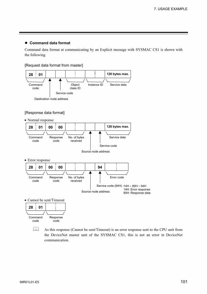
7. USAGE EXAMPLE
IMR01L01-E5 101
Command data format Command data format at communicating by an Explicit message with SYSMAC CS1 is shown with the following. [Request data format from master]
28 01 128 bytes max.
[Response data format]
• Normal response
28 01 00 00 128 bytes max.
• Error response
28 01 00 00 94 • Cannot be sent/Timeout
28 01
As this response (Cannot be sent/Timeout) is an error response sent to the CPU unit from the DeviceNet master unit of the SYSMAC CS1, this is not an error in DeviceNet communication.
Service data
Service data
Error code
Instance ID
No. of bytes received
No. of bytes received
Object class ID
Response code
Response code
Response code
Command code
Command code
Command code
Command code
Service code
Service code
14H + 80H = 94H 14H: Error response 80H: Response data
Service code (94H) :
Destination node address
Source node address
Source node address
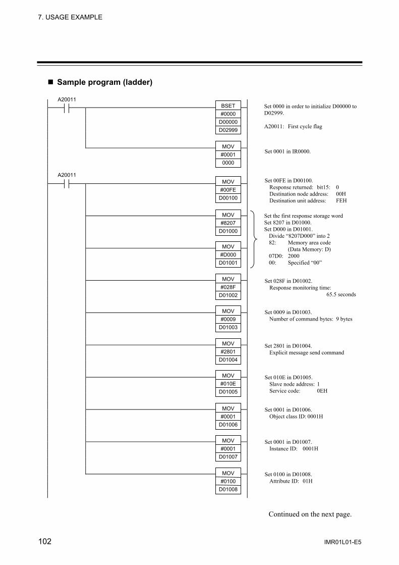
7. USAGE EXAMPLE
102 IMR01L01-E5
Sample program (ladder)
Continued on the next page.
Set 0000 in order to initialize D00000 to D02999. A20011: First cycle flag
Set 0001 in IR0000.
Set 00FE in D00100. Response returned: bit15: 0 Destination node address: 00H Destination unit address: FEH
Set the first response storage word Set 8207 in D01000. Set D000 in D01001.
Divide “8207D000” into 2 82: Memory area code (Data Memory: D) 07D0: 2000 00: Specified “00”
Set 028F in D01002. Response monitoring time: 65.5 seconds
Set 0009 in D01003. Number of command bytes: 9 bytes
Set 2801 in D01004. Explicit message send command
Set 010E in D01005. Slave node address: 1 Service code: 0EH
Set 0001 in D01006. Object class ID: 0001H
Set 0001 in D01007. Instance ID: 0001H
Set 0100 in D01008. Attribute ID: 01H
A20011
MOV #00010000
BSET#0000
D00000D02999
A20011 MOV
#00FED00100
MOV #8207
D01000
MOV #D000
D01001
MOV #028F
D01002
MOV #0009
D01003
MOV #2801
D01004
MOV #010E
D01005
MOV #0001
D01006
MOV #0001
D01007
MOV #0100
D01008

7. USAGE EXAMPLE
IMR01L01-E5 103
Continued from the previous page.
ASR 0000
000002 200112 CMP
#0000D02001
IOWR D00100 D01000
#00090000
MOV D02001D00006
ASR 0000
Compares contents of D02001 to 0000 after IOWR execution and response reception have been completed the previous cycle.
Places the contents of D02001 into D00006 if the comparison results is not equals (error).
Shifts the contents of IR0000 one bit right to turn ON IR000001.
Shifts the contents of IR0000 one bit right to turn ON (reset) IR000000.
000000 Shifts the contents of IR0000 one bit to the left to turn ON IR000001.
Transfers the 9 words of command data starting from D01000 at the CPU Unit to the DeviceNet Master Unit (unit number 0).
Transfer contents of D02004 (response data from slave: vendor ID) to D00010.
As the high-order and low-order bytes of data thus written are reversed, replace the high-order byte with the low-order byte.
Transfer contents of D00010 to D00000.
If the write for IOWR has been completed, IR0000 is shifted one bit to the right to turn ON (reset) IR000000.
If the write for IOWR has not been completed, IR0000 is shifted one bit to the left to turn ON IR000002.
200112
END
ASL 0000
MOV D02004D00010
SWAP&1
D00010
MOV D00010D00000
000001 ASR 0000
P_EQ ASL 0000
Message CommunicationsEnabled Flag
(ON after response received for messages communications executed a previous cycle)
Not Equals Flag
Message Communications
Enabled Flag
P_NE
P_NE

104 IMR01L01-E5
8. TROUBLESHOOTING
This section explains probable causes and treatment procedures if any abnormality occurs in the instrument. For any inquiries, please contact RKC sales office or the agent, to confirm the specifications of the product. If it is necessary to replace a device, always strictly observe the warnings below.
All wiring must be completed before power is turned on to prevent electric shock, instrument failure, or incorrect action.
Problem Possible cause Solution
No response (DeviceNet)
Wrong connection, no connection or disconnection of the DeviceNet communication cable
Confirm the connection method or condition and connect correctly
Breakage, wrong wiring, or imperfect contact of the DeviceNet communication cable
Confirm the wiring or connector and repair or replace the wrong one
Communication speed setting of COM-H and RKC controllers is mismatch
Confirm the communication speed setting and set that correctly
Wrong node address setting Confirm the address setting and set that correctly
Wrong RKC controllers address setting Sets following value to RKC controllers address - SR Mini HG: 0 - Others: Sets in order from 1
Continued on the next page.
CAUTION
To prevent electric shock or instrument failure, always turn off the system power before replacing the instrument.
To prevent electric shock or instrument failure, always turn off the power before mounting or removing the instrument.
To prevent electric shock or instrument failure, do not turn on the power until all wiring is completed. Make sure that the wiring is correct before applying power to the instrument.
To prevent electric shock or instrument failure, do not touch the inside of the instrument.
All wiring must be performed by authorized personnel with electrical experience in this type of work.
WARNING!
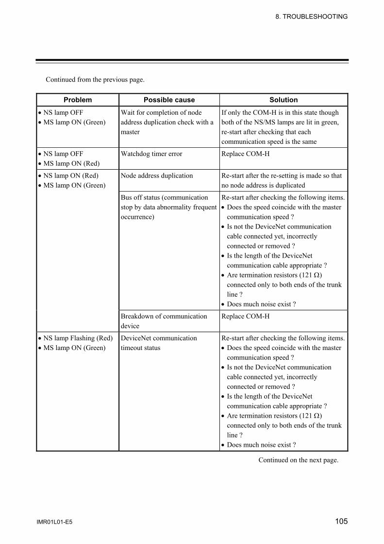
8. TROUBLESHOOTING
IMR01L01-E5 105
Continued from the previous page.
Problem Possible cause Solution
• NS lamp OFF • MS lamp ON (Green)
Wait for completion of node address duplication check with a master
If only the COM-H is in this state though both of the NS/MS lamps are lit in green, re-start after checking that each communication speed is the same
• NS lamp OFF • MS lamp ON (Red)
Watchdog timer error Replace COM-H
• NS lamp ON (Red) • MS lamp ON (Green)
Node address duplication Re-start after the re-setting is made so that no node address is duplicated
Bus off status (communication stop by data abnormality frequent occurrence)
Re-start after checking the following items.• Does the speed coincide with the master
communication speed ? • Is not the DeviceNet communication
cable connected yet, incorrectly connected or removed ?
• Is the length of the DeviceNet communication cable appropriate ?
• Are termination resistors (121 Ω) connected only to both ends of the trunk line ?
• Does much noise exist ?
Breakdown of communication device
Replace COM-H
• NS lamp Flashing (Red) • MS lamp ON (Green)
DeviceNet communication timeout status
Re-start after checking the following items.• Does the speed coincide with the master
communication speed ? • Is not the DeviceNet communication
cable connected yet, incorrectly connected or removed ?
• Is the length of the DeviceNet communication cable appropriate ?
• Are termination resistors (121 Ω) connected only to both ends of the trunk line ?
• Does much noise exist ?
Continued on the next page.
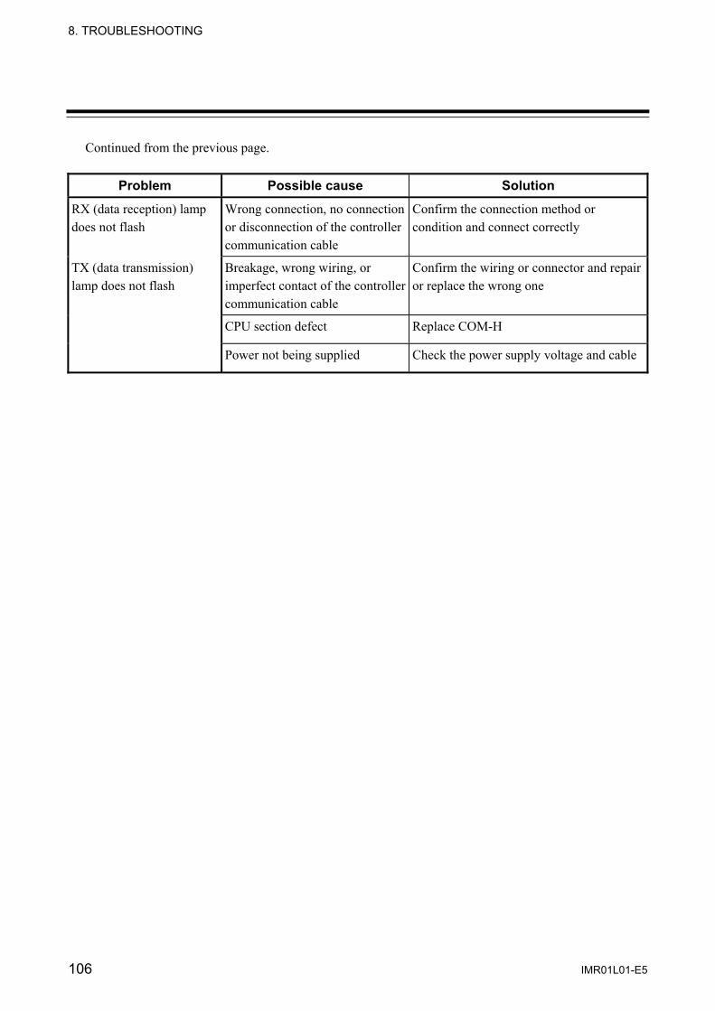
8. TROUBLESHOOTING
106 IMR01L01-E5
Continued from the previous page.
Problem Possible cause Solution
RX (data reception) lamp does not flash
Wrong connection, no connection or disconnection of the controller communication cable
Confirm the connection method or condition and connect correctly
TX (data transmission) lamp does not flash
Breakage, wrong wiring, or imperfect contact of the controller communication cable
Confirm the wiring or connector and repair or replace the wrong one
CPU section defect Replace COM-H
Power not being supplied Check the power supply voltage and cable

IMR01L01-E5 107
APPENDIX
A. Device Profiles A device profile is the specification that defined each necessary parameter with DeviceNet. Use it after understanding contents of a device profile of COM-H fully when connected to a master. A.1 Basic data General device data
Conforms to DeviceNet specification
Volume I -Release 2.0 Volume II -Release 2.0
Vender name RKC INSTRUMENT INC. (Vender ID = 394) Device profile name Generic Device Product catalog number Instruction manual number: IMR01L01-E (English)
IMR01L01-J (Japanese) Product revision 3.1
Physical conformance data
Network power consumption 50 mA @ 11 V DC 40 mA @ 24 V DC
Connector type Open-style connector or Micro-style connector Insulated physical layer Provided LEDs supported Module, Network MAC ID setting Rotary switch (Node address setting) Default MAC ID 63 Communication speed setting Rotary switch Communication speed supported 125 kbps, 250 kbps, 500 kbps
Communication data
Predefined master/slave connection set
Group 2 Only server
Dynamic connection supported (UCMM)
Not supported
Fragmented Explicit Messaging None

APPENDIX
108 IMR01L01-E5
A.2 Object mounting Identity Object (0x01: 01Hex) Object class
Attributes Not supported Services Not supported
Object instance
ID Description Get Set Type Value Attributes 1 Vender Yes No UINT 394 2 Product type Yes No UINT 0 3 Product code Yes No UINT 1 4 Revision
Major revision Minor revision
Yes No USINT USINT
3 1
5 Status (bits supported) Yes No WORD Note 1 6 Serial number Yes No UDINT Note 2 7 Product name
Length Name
Yes No USINT STRING
5 COM-H
DeviceNet service Parameter option Services 0x05 Reset 0 0x0E Get_Attribute_Single None
Note 1: A bit layout of “Status” Bit 0: Owned Bit 7: Become 1 when communication with a controller became abnormal and when the either bit of “Controller status” became 1. Bit 1 to 6 and Bit 8 to 15: Unused
Note 2: An individual number of every COM-H

APPENDIX
IMR01L01-E5 109
Message Router Object (0x02: 02Hex) Object class
Attributes Not supported Services Not supported
Object instance
Attributes Not supported Services Not supported
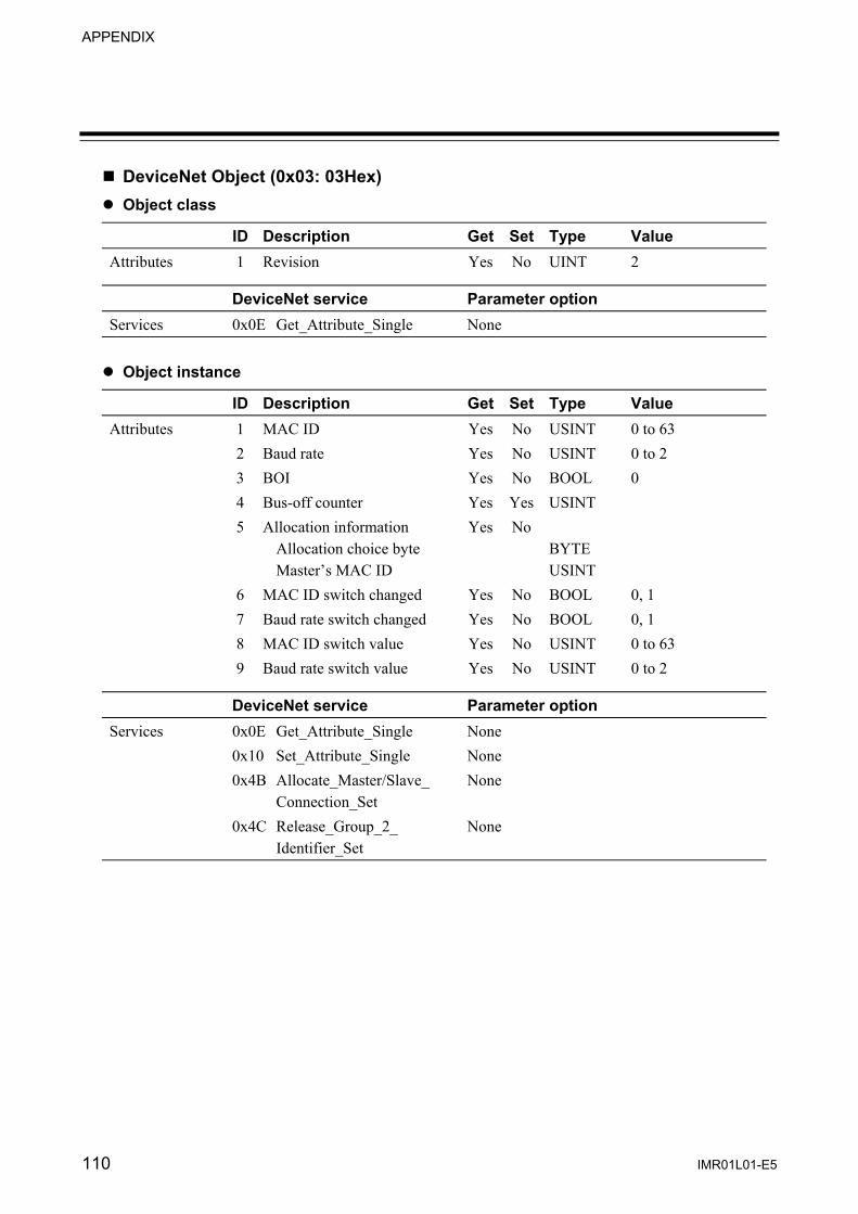
APPENDIX
110 IMR01L01-E5
DeviceNet Object (0x03: 03Hex) Object class
ID Description Get Set Type Value Attributes 1 Revision Yes No UINT 2
DeviceNet service Parameter option Services 0x0E Get_Attribute_Single None
Object instance
ID Description Get Set Type Value Attributes 1 MAC ID Yes No USINT 0 to 63 2 Baud rate Yes No USINT 0 to 2 3 BOI Yes No BOOL 0 4 Bus-off counter Yes Yes USINT 5 Allocation information
Allocation choice byte Master’s MAC ID
Yes No BYTE USINT
6 MAC ID switch changed Yes No BOOL 0, 1 7 Baud rate switch changed Yes No BOOL 0, 1 8 MAC ID switch value Yes No USINT 0 to 63 9 Baud rate switch value Yes No USINT 0 to 2
DeviceNet service Parameter option Services 0x0E Get_Attribute_Single None 0x10 Set_Attribute_Single None 0x4B Allocate_Master/Slave_
Connection_Set None
0x4C Release_Group_2_ Identifier_Set
None
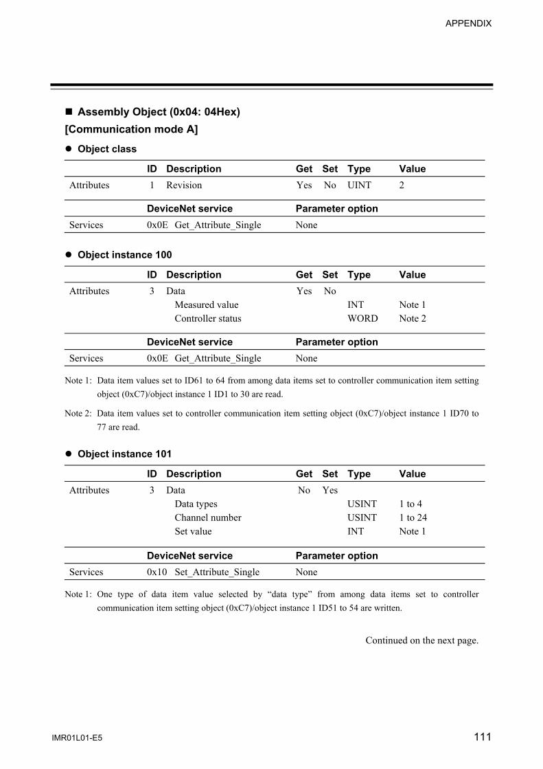
APPENDIX
IMR01L01-E5 111
Assembly Object (0x04: 04Hex) [Communication mode A]
Object class
ID Description Get Set Type Value Attributes 1 Revision Yes No UINT 2
DeviceNet service Parameter option Services 0x0E Get_Attribute_Single None
Object instance 100
ID Description Get Set Type Value Attributes 3 Data
Measured value Controller status
Yes No INT WORD
Note 1 Note 2
DeviceNet service Parameter option Services 0x0E Get_Attribute_Single None
Note 1: Data item values set to ID61 to 64 from among data items set to controller communication item setting object (0xC7)/object instance 1 ID1 to 30 are read.
Note 2: Data item values set to controller communication item setting object (0xC7)/object instance 1 ID70 to 77 are read.
Object instance 101
ID Description Get Set Type Value Attributes 3 Data
Data types Channel number Set value
No Yes USINT USINT INT
1 to 4 1 to 24 Note 1
DeviceNet service Parameter option Services 0x10 Set_Attribute_Single None
Note 1: One type of data item value selected by “data type” from among data items set to controller communication item setting object (0xC7)/object instance 1 ID51 to 54 are written.
Continued on the next page.

APPENDIX
112 IMR01L01-E5
Continued from the previous page. [Communication mode B]
Object class
ID Description Get Set Type Value Attributes 1 Revision Yes No UINT 2
DeviceNet service Parameter option Services 0x0E Get_Attribute_Single None
Object instance 100
ID Description Get Set Type Value Attributes 3 Data
Measured value 1 Measured value 2 Measured value 3 Measured value 4 Controller status
Yes No INT INT INT INT WORD
Note 1 Note 2
DeviceNet service Parameter option Services 0x0E Get_Attribute_Single None
Note 1: Data item values set to ID61 to 64 from among data items set to controller communication item setting object (0xC7)/object instance 1 ID1 to 30 are read.
Note 2: Data item values set to controller communication item setting object (0xC7)/object instance 1 ID70 to 77 are read.
Object instance 101
ID Description Get Set Type Value Attributes 3 Data
Data types Channel number Set value
No Yes USINT USINT INT
1 to 30 1 to 24 Note 1
DeviceNet service Parameter option Services 0x10 Set_Attribute_Single None
Note 1: One type of data item value selected by “data type” from among data items set to controller communication item setting object (0xC7)/object instance 1 ID1 to 30 are written.

APPENDIX
IMR01L01-E5 113
Connection Object (0x05: 05Hex) Object class
Attributes Not supported Services Not supported Number of maximum possible active connection
1
Object instance 1
Section Information Number of maximum instance
Instance type Explicit Message 1 Production trigger Cyclic Transport type Server Transport class 3
ID Description Get Set Type Value Attributes 1 State Yes No USINT 2 Instance type Yes No USINT 0x00 3 Transport class trigger Yes No BYTE 0x83 4 Produced connection ID Yes No UINT 5 Consumed connection ID Yes No UINT 6 Initial comm. Characteristics Yes No BYTE 0x21 7 Produced connection size Yes No UINT 7 8 Consumed connection size Yes No UINT 7 9 Expected packet rate Yes Yes UINT Default: 2500 12 Watchdog time-out action Yes Yes USINT 1, 3 13 Produced connection path
length Yes No UINT 0
14 Produced connection path Yes No (null) 15 Consumed connection path
length Yes No UINT 0
16 Consumed connection path Yes No (null)
DeviceNet service Parameter option Services 0x05 Reset None 0x0E Get_Attribute_Single None 0x10 Set_Attribute_Single None
Continued on the next page.
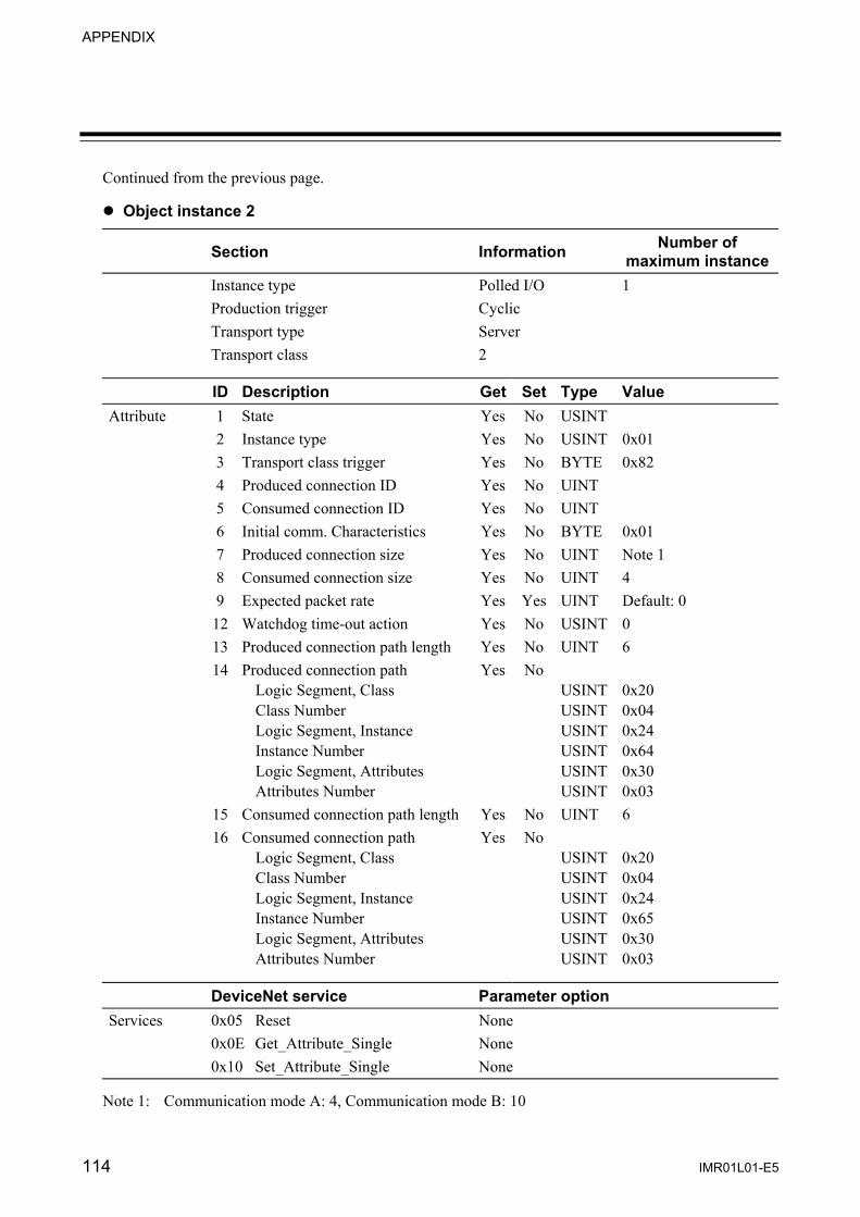
APPENDIX
114 IMR01L01-E5
Continued from the previous page. Object instance 2
Section Information Number of maximum instance
Instance type Polled I/O 1 Production trigger Cyclic Transport type Server Transport class 2
ID Description Get Set Type Value Attribute 1 State Yes No USINT 2 Instance type Yes No USINT 0x01 3 Transport class trigger Yes No BYTE 0x82 4 Produced connection ID Yes No UINT 5 Consumed connection ID Yes No UINT 6 Initial comm. Characteristics Yes No BYTE 0x01 7 Produced connection size Yes No UINT Note 1 8 Consumed connection size Yes No UINT 4 9 Expected packet rate Yes Yes UINT Default: 0 12 Watchdog time-out action Yes No USINT 0 13 Produced connection path length Yes No UINT 6 14 Produced connection path
Logic Segment, Class Class Number Logic Segment, Instance Instance Number Logic Segment, Attributes Attributes Number
Yes No USINTUSINTUSINTUSINTUSINTUSINT
0x20 0x04 0x24 0x64 0x30 0x03
15 Consumed connection path length Yes No UINT 6 16 Consumed connection path
Logic Segment, Class Class Number Logic Segment, Instance Instance Number Logic Segment, Attributes Attributes Number
Yes No USINTUSINTUSINTUSINTUSINTUSINT
0x20 0x04 0x24 0x65 0x30 0x03
DeviceNet service Parameter option Services 0x05 Reset None 0x0E Get_Attribute_Single None 0x10 Set_Attribute_Single None
Note 1: Communication mode A: 4, Communication mode B: 10

APPENDIX
IMR01L01-E5 115
Temperature Controller Object (0x64: 64Hex) Object class
Attributes Not supported Services Not supported
Object instance ( : 1 to 24)
ID Description Get Set Type Attributes 1 Data 1 Yes Yes INT 2 Data 2 Yes Yes INT 3 Data 3 Yes Yes INT 4 Data 4 Yes Yes INT 5 Data 5 Yes Yes INT 6 Data 6 Yes Yes INT 7 Data 7 Yes Yes INT 8 Data 8 Yes Yes INT 9 Data 9 Yes Yes INT 10 Data 10 Yes Yes INT 11 Data 11 Yes Yes INT 12 Data 12 Yes Yes INT 13 Data 13 Yes Yes INT 14 Data 14 Yes Yes INT 15 Data 15 Yes Yes INT 16 Data 16 Yes Yes INT 17 Data 17 Yes Yes INT 18 Data 18 Yes Yes INT 19 Data 19 Yes Yes INT 20 Data 20 Yes Yes INT 21 Data 21 Yes Yes INT 22 Data 22 Yes Yes INT 23 Data 23 Yes Yes INT 24 Data 24 Yes Yes INT 25 Data 25 Yes Yes INT 26 Data 26 Yes Yes INT 27 Data 27 Yes Yes INT 28 Data 28 Yes Yes INT 29 Data 29 Yes Yes INT 30 Data 30 Yes Yes INT
DeviceNet service Parameter option Services 0x0E Get_Attribute_Single None 0x10 Set_Attribute_Single None
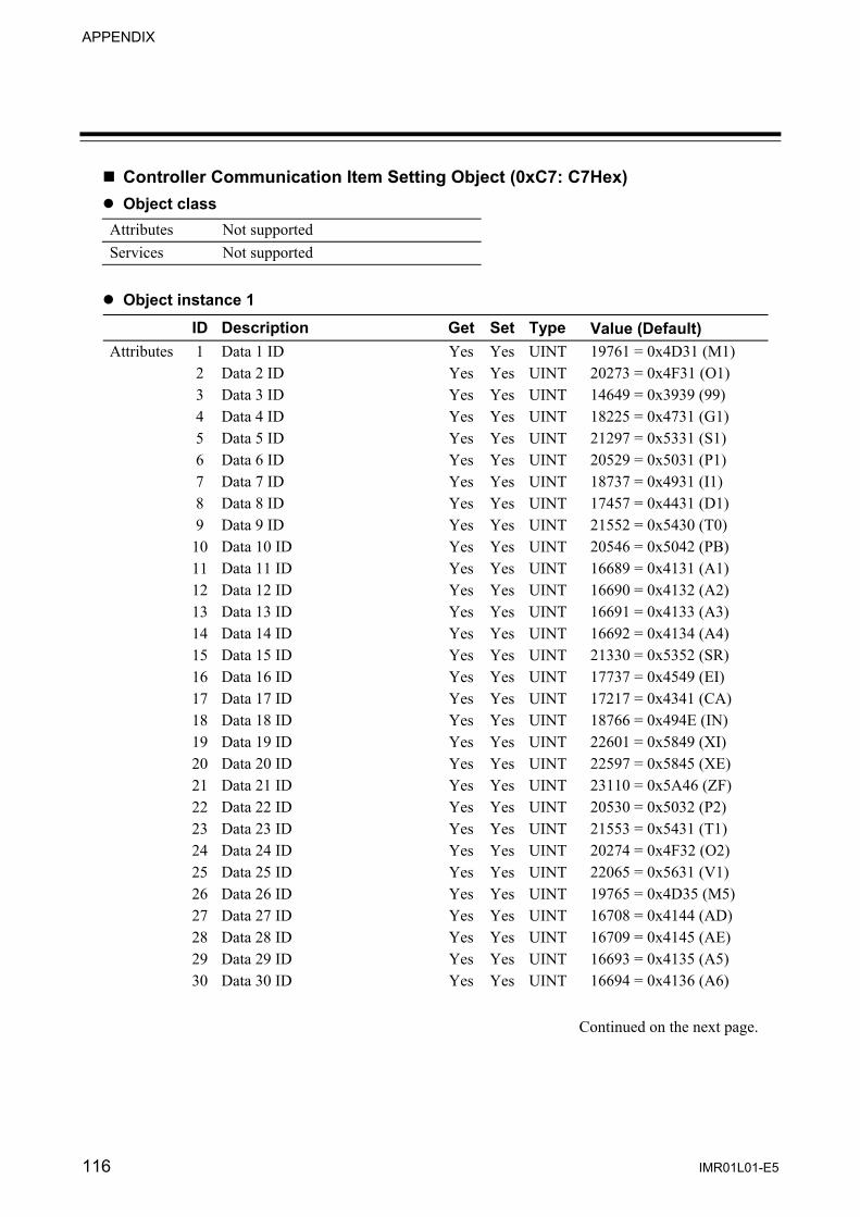
APPENDIX
116 IMR01L01-E5
Controller Communication Item Setting Object (0xC7: C7Hex) Object class
Attributes Not supported Services Not supported
Object instance 1
ID Description Get Set Type Value (Default) Attributes 1 Data 1 ID Yes Yes UINT 19761 = 0x4D31 (M1) 2 Data 2 ID Yes Yes UINT 20273 = 0x4F31 (O1) 3 Data 3 ID Yes Yes UINT 14649 = 0x3939 (99) 4 Data 4 ID Yes Yes UINT 18225 = 0x4731 (G1) 5 Data 5 ID Yes Yes UINT 21297 = 0x5331 (S1) 6 Data 6 ID Yes Yes UINT 20529 = 0x5031 (P1) 7 Data 7 ID Yes Yes UINT 18737 = 0x4931 (I1) 8 Data 8 ID Yes Yes UINT 17457 = 0x4431 (D1) 9 Data 9 ID Yes Yes UINT 21552 = 0x5430 (T0) 10 Data 10 ID Yes Yes UINT 20546 = 0x5042 (PB) 11 Data 11 ID Yes Yes UINT 16689 = 0x4131 (A1) 12 Data 12 ID Yes Yes UINT 16690 = 0x4132 (A2) 13 Data 13 ID Yes Yes UINT 16691 = 0x4133 (A3) 14 Data 14 ID Yes Yes UINT 16692 = 0x4134 (A4) 15 Data 15 ID Yes Yes UINT 21330 = 0x5352 (SR) 16 Data 16 ID Yes Yes UINT 17737 = 0x4549 (EI) 17 Data 17 ID Yes Yes UINT 17217 = 0x4341 (CA) 18 Data 18 ID Yes Yes UINT 18766 = 0x494E (IN) 19 Data 19 ID Yes Yes UINT 22601 = 0x5849 (XI) 20 Data 20 ID Yes Yes UINT 22597 = 0x5845 (XE) 21 Data 21 ID Yes Yes UINT 23110 = 0x5A46 (ZF) 22 Data 22 ID Yes Yes UINT 20530 = 0x5032 (P2) 23 Data 23 ID Yes Yes UINT 21553 = 0x5431 (T1) 24 Data 24 ID Yes Yes UINT 20274 = 0x4F32 (O2) 25 Data 25 ID Yes Yes UINT 22065 = 0x5631 (V1) 26 Data 26 ID Yes Yes UINT 19765 = 0x4D35 (M5) 27 Data 27 ID Yes Yes UINT 16708 = 0x4144 (AD) 28 Data 28 ID Yes Yes UINT 16709 = 0x4145 (AE) 29 Data 29 ID Yes Yes UINT 16693 = 0x4135 (A5) 30 Data 30 ID Yes Yes UINT 16694 = 0x4136 (A6)
Continued on the next page.

APPENDIX
IMR01L01-E5 117
Continued from the previous page.
ID Description Get Set Type Value (Default) Attributes 51 I/O message
SV 1 ID number Yes Yes UINT 5 (1 to 30)
52 I/O message SV 2 ID number
Yes Yes UINT 0 (1 to 30)
53 I/O message SV 3 ID number
Yes Yes UINT 0 (1 to 30)
54 I/O message SV 4 ID number
Yes Yes UINT 0 (1 to 30)
61 I/O message PV 1 ID number
Yes Yes UINT 1 (1 to 30)
62 I/O message PV 2 ID number
Yes Yes UINT 26 (1 to 30)
63 I/O message PV 3 ID number
Yes Yes UINT 0 (1 to 30)
64 I/O message PV 4 ID number
Yes Yes UINT 0 (1 to 30)
70 I/O message Controller status Bit 0
Yes Yes UINT 12336 = 0x3030 (00)
71 I/O message Controller status Bit 1
Yes Yes UINT 12336 = 0x3030 (00)
72 I/O message Controller status Bit 2
Yes Yes UINT 16708 = 0x4144 (AD)
73 I/O message Controller status Bit 3
Yes Yes UINT 16709 = 0x4145 (AE)
74 I/O message Controller status Bit 4
Yes Yes UINT 16705 = 0x4141 (AA)
75 I/O message Controller status Bit 5
Yes Yes UINT 16706 = 0x4142 (AB)
76 I/O message Controller status Bit 6
Yes Yes UINT 16945 = 0x4231 (B1)
77 I/O message Controller status Bit 7
Yes Yes UINT 16707 = 0x4143 (AC)
80 Number of maximum connection channels
Yes Yes UINT 20
DeviceNet service Parameter option Services 0x0E Get_Attribute_Single None 0x10 Set_Attribute_Single None
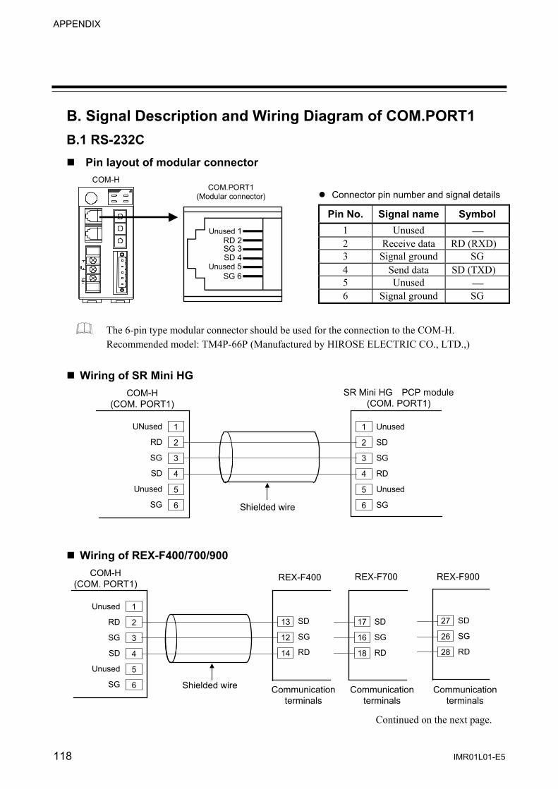
APPENDIX
118 IMR01L01-E5
B. Signal Description and Wiring Diagram of COM.PORT1 B.1 RS-232C Pin layout of modular connector
Pin No. Signal name Symbol 1 Unused ⎯ 2 Receive data RD (RXD) 3 Signal ground SG 4 Send data SD (TXD) 5 Unused ⎯ 6 Signal ground SG
The 6-pin type modular connector should be used for the connection to the COM-H. Recommended model: TM4P-66P (Manufactured by HIROSE ELECTRIC CO., LTD.,)
Wiring of SR Mini HG
1
Shielded wire
UNused
RD
SG
SD
Unused
SG
Unused
SD
SG
RD
Unused
SG
COM-H (COM. PORT1)
2
3
4
5
6
1
2
3
4
5
6
SR Mini HG PCP module (COM. PORT1)
Wiring of REX-F400/700/900
1
Shielded wire
Unused
RD
SG
SD
Unused
SG
SD
SG
RD
COM-H (COM. PORT1)
2
3
4
5
6
13
12
14
REX-F400
SD
SG
RD
17
16
18
REX-F700
SD
SG
RD
27
26
28
REX-F900
Communicationterminals
Communication terminals
Communicationterminals
Continued on the next page.
Connector pin number and signal details
COM.PORT1
(Modular connector)
Unused 1RD 2SG 3SD 4
Unused 5SG 6
COM-H
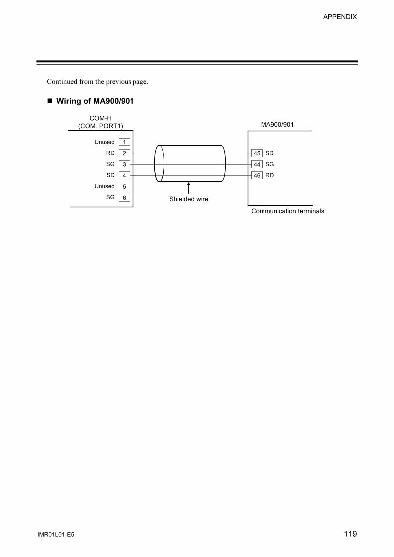
APPENDIX
IMR01L01-E5 119
Continued from the previous page. Wiring of MA900/901
1
Shielded wire
Unused
RD
SG
SD
Unused
SG
SD
SG
RD
COM-H (COM. PORT1)
2
3
4
5
6
45
44
46
MA900/901
Communication terminals

APPENDIX
120 IMR01L01-E5
B.2 RS-422A Pin layout of modular connector
Pin No. Signal name Symbol 1 Send data T (A) 2 Send data T (B) 3 Signal ground SG 4 Receive data R (B) 5 Receive data R (A) 6 Signal ground SG
The 6-pin type modular connector should be used for the connection to the COM-H. Recommended model: TM4P-66P (Manufactured by HIROSE ELECTRIC CO., LTD.,)
B.2.1 Connection to the RS-422A interface of the controllers
Wiring of SR Mini HG
1
Shielded twisted pair wire
Paired wire
T (A)
T (B)
SG
R (B)
R (A)
SG
R (A)
R (B)
SG
T (B)
T (A)
SG
COM-H (COM. PORT1)
2
3
4
5
6
1
2
3
4
5
6
SR Mini HG PCP module (COM. PORT1)
(+)
(−)
(+)
(−)
(+)
(−)
(+)
(−)
Wiring of REX-F400/700/900
1
Shielded twisted pair wire
Paired wire
T (A)
T (B)SG
R (B)
R (A)
SG
R (A)
R (B)
SG T (B)
T (A)
COM-H (COM. PORT1)
2
3
4
5
6
15
16
12
14
13
REX-F400
R (A)
R (B) SG
T (B)
T (A)
19
20
16
18
17
REX-F700
29
30
26
28
27
REX-F900
R (A)
R (B) SG
T (B)
T (A)
Communication terminals
Communication terminals
Communication terminals
(+)
(−)
(+)
(−)
(+)
(−)
(+)
(−)
(+)
(−)
(+)
(−)
(+)
(−)
(+)
(−)
Modular connector
(COM.PORT1)
T (A) 1T (B) 2SG 3R (B) 4R (A) 5SG 6
COM-H
Connector pin number and

APPENDIX
IMR01L01-E5 121
Wiring of MA900/901
1
Shielded twisted pair wire
Paired wire
T (A)
T (B)
SG
R (B)
R (A)
SG
R (A)
R (B)
SG
T (B)
T (A)
COM-H (COM. PORT1)
2
3
4
5
6
47
48
44
46
45
MA900/901
Communication terminals
(+)
(−)
(+)
(−)
(+)
(−)
(+)
(−)
Wiring of REX-PG410
1
Shielded twisted pair wire
Paired wire
T (A)
T (B)
SG
R (B)
R (A)
SG
R (A)
R (B)
SG
T (B)
T (A)
COM-H (COM. PORT1)
2
3
4
5
6
15
16
12
14
13
REX-PG410
Communication terminals
*R
*R
*R: Termination resistors (Example: 120 Ω 1/2 W) If communication errors occur frequently due to the operation environment or the communication distance, connect termination resistors.
(+)
(−)
(+)
(−)
(+)
(−)
(+)
(−)

APPENDIX
IMR01L01-E5 122
B.2.2 Connection to the RS-485 interface of the controllers
When connected to the RS-485 interface controller by using the RS-422A interface for COM-H control communication, connect T (A) and R (A) of the cable to the controller T/R (A) terminals and also T (B) and R (B) of the cable to the controller T/R (B) terminals, respectively. Wiring of REX-F400/700/900
1 T (A)T (B)
SG
R (B)
R (A)SG
T/R (A)
T/R (B)
SG
COM-H (COM. PORT1)
2
3
4
5
6
13
14
12
REX-F400 REX-F700 REX-F900
T/R (A)
T/R (B)
SG
17
18
16
T/R (A)
T/R (B)
SG
27
28
26 *R
Shielded twisted pair wire
Paired wire
Communication terminals
Communication terminals
Communication terminals
*R: Termination resistors (Example: 120 Ω 1/2 W) If communication errors occur frequently due to the operation environment or the communication distance, connect termination resistors.
(+)
(−)
(+)
(−)
(+)
(−)
(+)
(−)
(+)
(−)
Wiring of CB100/400/500/700/900
1 T (A)
T (B)
SG
R (B)
R (A)
SG
T/R (A)
T/R (B)
SG
COM-H (COM. PORT1)
2
3
4
5
6
14
15
13
CB100/400/500/900
*R
Shielded twisted pair wire
Paired wire
Communication terminals
(+)
(−)
(+)
(−)
(+)
(−)
1 T (A)
T (B)
SG
R (B)
R (A)
SG
T/R (A)
T/R (B)
SG
COM-H (COM. PORT1)
2
3
4
5
6
8
9
7
CB700
*R
Shielded twisted pair wire
Paired wire
Communication terminals *R: Termination resistors (Example: 120 Ω 1/2 W)
If communication errors occur frequently due to the operation environment or the communication distance, connect termination resistors.
(+)
(−)
(+)
(−)
(+)
(−)

APPENDIX
IMR01L01-E5 123
Wiring of SA100
1 T (A)
T (B)
SG
R (B)
R (A)
SG
T/R (A)
T/R (B)
SG
COM-H (COM. PORT1)
2
3
4
5
6
2
3
1
SA100
*R
Shielded twisted pair wire
Paired wire
Communication connector *R: Termination resistors (Example: 120 Ω 1/2 W)
If communication errors occur frequently due to the operation environment or the communication distance, connect termination resistors.
(+)
(−)
(+)
(−)
(+)
(−)
Wiring of SA200
1 T (A)
T (B)
SG
R (B)
R (A)
SG
T/R (A)
T/R (B)
SG
COM-H (COM. PORT1)
2
3
4
5
6
11
12
10
SA200
*R
Shielded twisted pair wire
Paired wire
Communication terminals *R: Termination resistors (Example: 120 Ω 1/2 W)
If communication errors occur frequently due to the operation environment or the communication distance, connect termination resistors.
(+)
(−)
(+)
(−)
(+)
(−)
Wiring of MA900/901
1 T (A)
T (B)
SG
R (B)
R (A)
SG
T/R (A)
T/R (B)
SG
COM-H (COM. PORT1)
2
3
4
5
6
45
46
44
MA900/901
*R
Shielded twisted pair wire
Paired wire
Communication terminals *R: Termination resistors (Example: 120 Ω 1/2 W)
If communication errors occur frequently due to the operation environment or the communication distance, connect termination resistors.
(+)
(−)
(+)
(−)
(+)
(−)

APPENDIX
IMR01L01-E5 124
Wiring of LE100
1 T (A)
T (B)
SG
R (B)
R (A)
SG
T/R (A)
T/R (B)
SG
COM-H (COM. PORT1)
2
3
4
5
6
2
3
1
LE100
*R
Shielded twisted pair wire
Paired wire
Connector *R: Termination resistors (Example: 120 Ω 1/2 W)
If communication errors occur frequently due to the operation environment or the communication distance, connect termination resistors.
(+)
(−)
(+)
(−)
(+)
(−)
Wiring of REX-PG410
1 T (A)
T (B)
SG
R (B)
R (A)
SG
T/R (A)
T/R (B)
SG
COM-H (COM. PORT1)
2
3
4
5
6
13
14
12
REX-PG410
*R
Shielded twisted pair wire
Paired wire
Communication terminals *R: Termination resistors (Example: 120 Ω 1/2 W)
If communication errors occur frequently due to the operation environment or the communication distance, connect termination resistors.
(+)
(−)
(+)
(−)
(+)
(−)

The first edition: OCT. 2001 The fifth edition: AUG. 2010 [IMQ00]

IMR01L01-E5 AUG. 2010
RKC INSTRUMENT INC.
HEADQUARTERS: 16-6, KUGAHARA 5-CHOME, OHTA-KU TOKYO 146-8515 JAPAN PHONE: 03-3751-9799 (+81 3 3751 9799) FAX: 03-3751-8585 (+81 3 3751 8585) E-mail: [email protected] Website: http://www.rkcinst.com/
R


![Z-CT Instruction Manual [Detailed version] · Z-CT Instruction Manual [Detailed version] ® RKC INSTRUMENT INC. Current Transforme r Input Module (800) ... • CTL-12-S56-10L-N (0.0](https://img.pdfslide.net/doc/110x75/5f07bd2e7e708231d41e7f2a/z-ct-instruction-manual-detailed-version-z-ct-instruction-manual-detailed-version.jpg)


![SRZ Instruction Manual [For PLC Communicatio] - RKC …€¦ · · 2015-12-21RKC INSTRUMENT INC. IMS01T13-E3 ® SRZ Instruction Manual [For PLC Communication] Module Type Controller](https://img.pdfslide.net/doc/110x75/5ade87487f8b9aa5088e4944/srz-instruction-manual-for-plc-communicatio-rkc-2015-12-21rkc-instrument.jpg)