Embed Size (px)
Citation preview

Getting Started
2010 SERIES
Squirrel Data Logger
www.omniinstruments.co.uk

28507 Version 6 SQ2010 Page 1
Contents
1. Hardware Checklist .......................................................................... 2
2. General Information ......................................................................... 3
3. Installing Software and USB Drivers .............................................. 4
4. Quick Start Example ........................................................................ 5
5. Download Process Explained ......................................................... 9
6. Menu and Navigation ..................................................................... 10
7. Connections ................................................................................... 14
8. Accessories .................................................................................... 16
9. Specifications ................................................................................. 18
10. Declaration of Conformity ................................... Inside rear cover
After reading this guide please re-fer to the Help contents within SquirrelView (press F1) for further details on your logger and how to use it with the software.

SQ2010 28507 Version 6 Page 2
EN
SQ2010 Standard contents
A) Carry caseB) SQ2010 LoggerC) CD containing software (SQA100)D) Getting Started manual (this booklet)E) USB Cable (LC77)F) Batteries, 2 x CG) Current shunt resistors for 4 to 20mA inputs, 10R x 4 (CS202)H) Connectors: 6 way x 2 (18097), 3 way x 1 (14174) with cable
ties
1. Hardware Checklist
A
B C
E
F G H
D

28507 Version 6 SQ2010 Page 3
2. General Information
The 2010 uses two C size alkaline batteries located under the removable cover on the rear of the unit as shown below. To insert new or change the existing batteries:
1. Open the battery cover by releasing the clip (highlighted)2. Insert 2 C* batteries, ensuring the correct polarity3. Refit the battery cover
* It is recommended that all replacement batteries are of the same manufacturer, typeand condition.
Battery indicator When logging please ensure that the batteries in the unit have sufficient capacity to complete the logging task. This can be checked via the battery indicator located in the top right of the display.
HIGH LOW CAPACITY CAPACITY
External power indicator The logger may be powered from an external source (8-28V DC or USB)
Important: To ensure data protection in the case of an unexpected power loss, please ensure that batteries are fitted whilst the unit is operational.
2.1 Installing the batteries
2.2 Power indicator
- +
Important: Remove the batteries when the logger is not used for long periods of time or is being transported
SQ2010 28507 Version 6 Page 4
EN
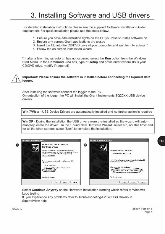
3. Installing Software and USB drivers
Select Continue Anyway on the Hardware Installation warning which refers to Windows Logo testing. If you experience any problems refer to Troubleshooting->20xx USB Drivers in SquirrelView help
Win XP - During the installation the USB drivers were pre-installed so the wizard will auto-matically locate the driver. On the „Found New Hardware Wizard‟ select „No, not this time‟ and for all the other screens select „Next‟ to complete the installation.
After installing the software connect the logger to the PC. On detection of the logger the PC will install the Grant Instruments SQ20XX USB device drivers
Win 7/Vista - USB Device Drivers are automatically installed and no further action is required
Important: Please ensure the software is installed before connecting the Squirrel data logger.
* If after a few minutes autorun has not occurred select the Run option from the WindowsStart Menu. In the Command Line box, type d:\setup and press enter (where d:\ is your CD\DVD drive, modify if required)
For detailed installation instructions please see the supplied „Software Installation Guide‟ supplement. For quick installation please see the steps below;
1. Ensure you have administration rights on the PC you wish to install software on2. Ensure any current Grant applications are closed3. Insert the CD into the CD\DVD drive of your computer and wait for it to autorun*4. Follow the on screen installation wizard
28507 Version 6 SQ2010 Page 5
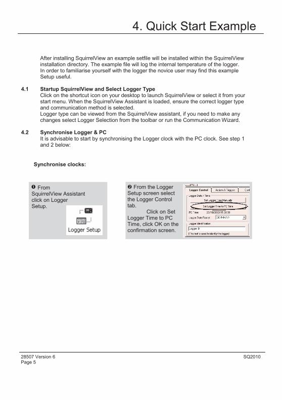
4. Quick Start Example
After installing SquirrelView an example setfile will be installed within the SquirrelView installation directory. The example file will log the internal temperature of the logger. In order to familiarise yourself with the logger the novice user may find this example Setup useful.
4.1 Startup SquirrelView and Select Logger Type Click on the shortcut icon on your desktop to launch SquirrelView or select it from your start menu. When the SquirrelView Assistant is loaded, ensure the correct logger type and communication method is selected. Logger type can be viewed from the SquirrelView assistant, if you need to make any changes select Logger Selection from the toolbar or run the Communication Wizard.
4.2 Synchronise Logger & PC It is advisable to start by synchronising the Logger clock with the PC clock. See step 1 and 2 below:
Synchronise clocks:
From SquirrelView Assistant click on Logger Setup.
From the Logger Setup screen select the Logger Control tab.
Click on Set Logger Time to PC Time, click OK on the confirmation screen.
SQ2010 28507 Version 6 Page 6
EN
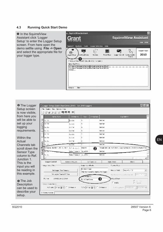
The Logger Setup screen is now visible, from here you will be able to set up your logging requirements.
Within the Actual Channels tab scroll down the Sensor Type column to Ref. Junction 1. This is the input you will be reading in this example.
The Job Description can be used to describe your setup.
In the SquirrelView Assistant click „Logger Setup‟ to enter the Logger Setup screen. From here open the demo setfile using File -> Open and select the appropriate file for your logger type.
4.3 Running Quick Start Demo

28507 Version 6 SQ2010 Page 7
Click to send setup to logger and start logging. Let the unit log for a few minutes.
Click for Squirrel-View Assistant.
Click if you wish to meter the input in Real Time.
Click on Logger Control icon to pause or stop the logging process.
In the Logger Control window you can view relevant information on the state of the logger. To stop logging click on the stop button.
To Download the logger click on the „Download Data‟ icon from the SquirrelView As-sistant.
SQ2010 28507 Version 6 Page 8
EN
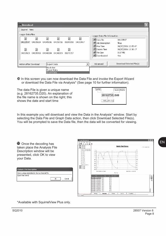
In this screen you can now download the Data File and invoke the Export Wizard or download the Data File via Analysis* (See page 10 for further information).
The data File is given a unique name (e.g. 28162735.D20). An explanation of the file name is shown on the right; this shows the date and start time
In this example you will download and view the Data in the Analysis* window. Start by selecting the Data File and Graph Data action, then click Download Selected File(s). You will be prompted to save the Data file, then the data will be converted for viewing.
Once the decoding has taken place the Analysis File Description window will be presented, click OK to view your Data.
*Available with SquirrelView Plus only.

28507 Version 6 SQ2010 Page 9
5. Download Process Explained
The Diagram above shows the download process. Data in the logger is written to the internal memory and may be downloaded by SquirrelView.
Before the data can be viewed it must be converted by SquirrelView for Analysis or exported to .csv or .xls format depending on the PC software being used.
The conversion process can be performed in one of three ways within SquirrelView:
from SquirrelView assistant->Analysis->Export Data File
automatically when using the download Data button from SquirrelView*
or from the Logger Data Analysis screen by selecting File->Import Data*
Once the file has been downloaded it can be double clicked to open it with the program specified under „Tools‟, „Preferences‟, „File Association Action‟.
*Available with SquirrelView Plus only.
Logger
Data Files
Analysis File (Plus Only)
Analysis (.d20)
Export
(.xls)
(.csv)
Comma Separated Values
Microsoft Excel
SquirrelView
SQ2010 28507 Version 6 Page 10
EN
6. Menu and Navigation
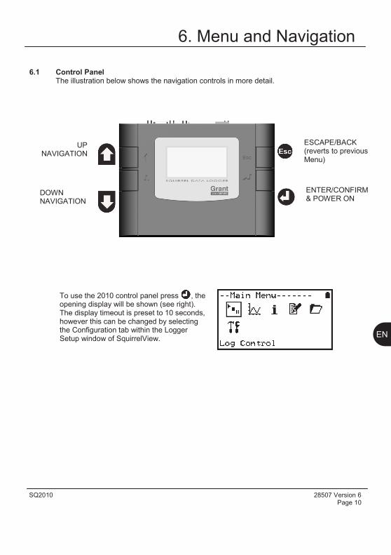
6.1 Control Panel The illustration below shows the navigation controls in more detail.
To use the 2010 control panel press , the opening display will be shown (see right). The display timeout is preset to 10 seconds, however this can be changed by selecting the Configuration tab within the Logger Setup window of SquirrelView.
UP NAVIGATION
DOWN NAVIGATION
ENTER/CONFIRM & POWER ON
ESCAPE/BACK (reverts to previous Menu)

28507 Version 6 SQ2010 Page 11
6.2 Control panel menu
6.2.1 Log Control In this menu you can Arm (activate) or Disarm (deactivate) the logger.
6.2.2 Meter Here you can view each channel in Real Time (at 1-2Hz). Use the enter key for a graphical view of a channel.
6.2.3 Status The Status menu gives you access to information relating to the logger, such as available memory and the power supply voltage. It is also possible to override the alarm outputs from here.
6.2.4 Setup This contains menus for setting the Language, Time, Date, basic Channel Setup, storing and recalling setups and Delayed start.
See 6.3 for more details on basic setup
6.2.5 Data Files This menu allows you delete the data files held within the loggers memory.
6.2.6 Tools The Tools menu contains maintenance type functions such as querying the software version of the logger, performing a self test and resetting the logger.
Detailed below is a basic explanation of the top menu structure. For more information on the whole menu structure please refer to the Help->Help Content->Loggers within SquirrelView.
SQ2010 28507 Version 6 Page 12
EN
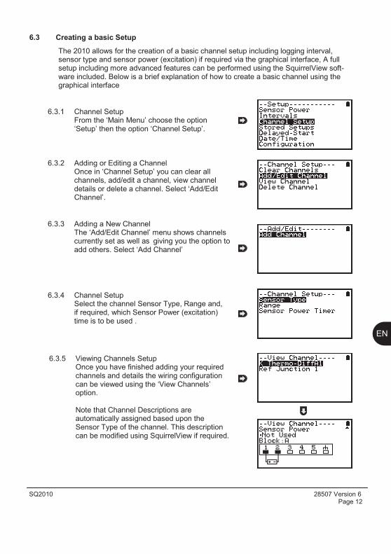
The 2010 allows for the creation of a basic channel setup including logging interval, sensor type and sensor power (excitation) if required via the graphical interface, A full setup including more advanced features can be performed using the SquirrelView soft-ware included. Below is a brief explanation of how to create a basic channel using the graphical interface
6.3.1 Channel Setup From the „Main Menu‟ choose the option „Setup‟ then the option „Channel Setup‟.
6.3.2 Adding or Editing a Channel Once in „Channel Setup‟ you can clear all channels, add/edit a channel, view channel details or delete a channel. Select „Add/EditChannel‟.
6.3.3 Adding a New Channel The „Add/Edit Channel‟ menu shows channels currently set as well as giving you the option to add others. Select „Add Channel‟
6.3.4 Channel Setup Select the channel Sensor Type, Range and, if required, which Sensor Power (excitation) time is to be used .
6.3.5 Viewing Channels Setup Once you have finished adding your required channels and details the wiring configuration can be viewed using the „View Channels‟ option.
Note that Channel Descriptions are automatically assigned based upon the Sensor Type of the channel. This description can be modified using SquirrelView if required.
6.3 Creating a basic Setup
28507 Version 6 SQ2010 Page 13
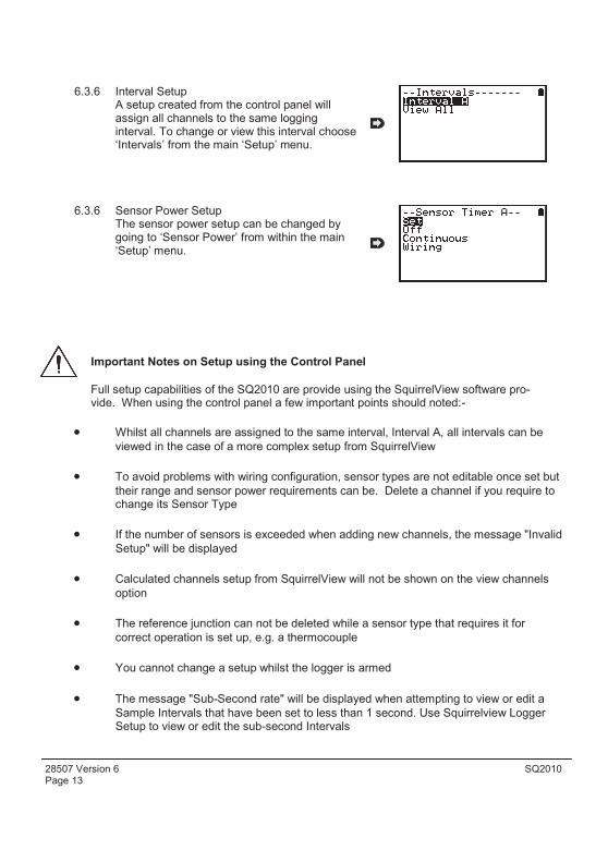
Important Notes on Setup using the Control Panel
Full setup capabilities of the SQ2010 are provide using the SquirrelView software pro-vide. When using the control panel a few important points should noted:-
6.3.6 Interval Setup A setup created from the control panel will assign all channels to the same logging interval. To change or view this interval choose „Intervals‟ from the main „Setup‟ menu.
6.3.6 Sensor Power Setup The sensor power setup can be changed by going to „Sensor Power‟ from within the main „Setup‟ menu.
Whilst all channels are assigned to the same interval, Interval A, all intervals can be
viewed in the case of a more complex setup from SquirrelView
To avoid problems with wiring configuration, sensor types are not editable once set but
their range and sensor power requirements can be. Delete a channel if you require tochange its Sensor Type
If the number of sensors is exceeded when adding new channels, the message "Invalid
Setup" will be displayed
Calculated channels setup from SquirrelView will not be shown on the view channels
option
The reference junction can not be deleted while a sensor type that requires it for
correct operation is set up, e.g. a thermocouple
You cannot change a setup whilst the logger is armed
The message "Sub-Second rate" will be displayed when attempting to view or edit a
Sample Intervals that have been set to less than 1 second. Use Squirrelview LoggerSetup to view or edit the sub-second Intervals
SQ2010 28507 Version 6 Page 14
EN
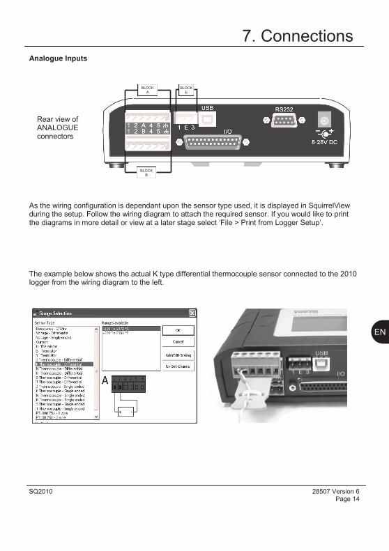
7. Connections
As the wiring configuration is dependant upon the sensor type used, it is displayed in SquirrelView during the setup. Follow the wiring diagram to attach the required sensor. If you would like to print the diagrams in more detail or view at a later stage select „File > Print from Logger Setup‟.
Analogue Inputs
The example below shows the actual K type differential thermocouple sensor connected to the 2010 logger from the wiring diagram to the left.
Rear view of ANALOGUE connectors
BLOCK
A BLOCK
E
BLOCK
B
28507 Version 6 SQ2010 Page 15
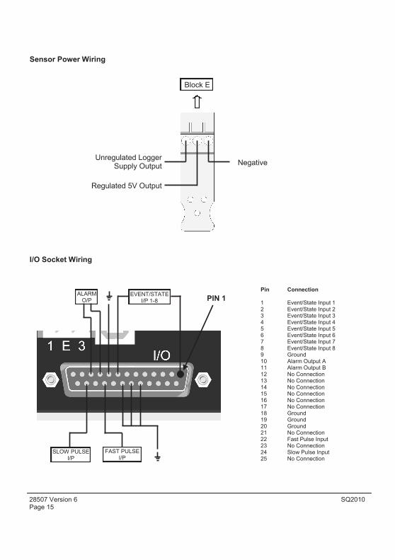
I/O Socket Wiring
Sensor Power Wiring
ALARM O/P
EVENT/STATE I/P 1-8 PIN 1
SLOW PULSE I/P
FAST PULSE I/P
Unregulated Logger Supply Output
Regulated 5V Output
Block E
Pin Connection
1 Event/State Input 1 2 Event/State Input 2 3 Event/State Input 3 4 Event/State Input 4 5 Event/State Input 5 6 Event/State Input 6 7 Event/State Input 7 8 Event/State Input 8 9 Ground 10 Alarm Output A 11 Alarm Output B 12 No Connection 13 No Connection 14 No Connection 15 No Connection 16 No Connection 17 No Connection 18 Ground 19 Ground 20 Ground 21 No Connection 22 Fast Pulse Input 23 No Connection 24 Slow Pulse Input 25 No Connection
Negative

SQ2010 28507 Version 6 Page 16
EN
8. Accessories
Grant Instruments supply a wide range of accessories to compliment the range of Squirrel data loggers. These include GSM Modem and Ethernet converters and wireless adapter as shown below, all of which allow you to contact any Squirrel data logger remotely or where no land line exists. All are very easy to install and connect directly to the logger via RS232. If you need any further details or wish to make a purchase please contact Grant or your local supplier for more details.
RS232 to Ethernet Converter consisting of adaptor box and modem setup Part No: Cable. Ethernet configuration software is suitable for Windows XP only. SQ20A801
GSM Modem kit comprising of modem , Squirrel connection cable, power lead and antenna with 3m lead. A data-enabled SIM card will also be required from your network service provider. SQ20A802
Wireless Adaptor comprising of an RS232 adaptor for connecting the logger to the PC at baud rates up to 115K2 with a range of up to 200 metres using the 2.4GHz frequency band. The kit is supplied with all connecting leads. Note: power supplies (MPU 12V) need to be ordered separately SQ20A803
GSM Wireless
Ethernet
28507 Version 6 SQ2010 Page 17
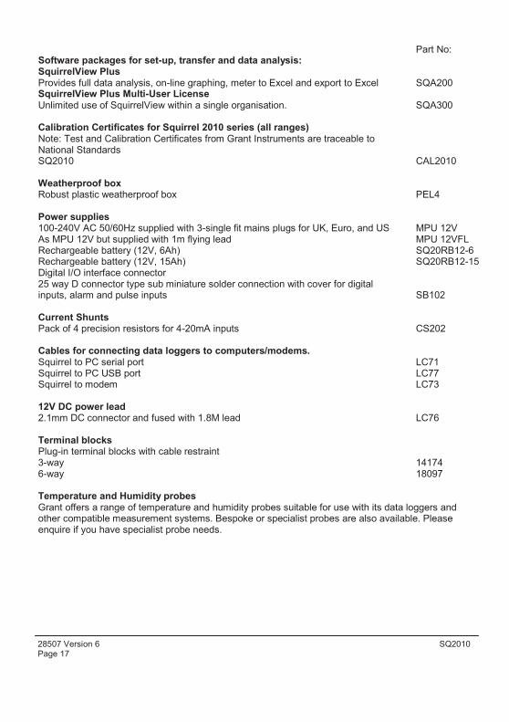
Part No: Software packages for set-up, transfer and data analysis: SquirrelView Plus Provides full data analysis, on-line graphing, meter to Excel and export to Excel SQA200 SquirrelView Plus Multi-User License Unlimited use of SquirrelView within a single organisation. SQA300
Calibration Certificates for Squirrel 2010 series (all ranges) Note: Test and Calibration Certificates from Grant Instruments are traceable to National Standards SQ2010 CAL2010
Weatherproof box Robust plastic weatherproof box PEL4
Power supplies 100-240V AC 50/60Hz supplied with 3-single fit mains plugs for UK, Euro, and US MPU 12V As MPU 12V but supplied with 1m flying lead MPU 12VFL Rechargeable battery (12V, 6Ah) SQ20RB12-6 Rechargeable battery (12V, 15Ah) SQ20RB12-15 Digital I/O interface connector 25 way D connector type sub miniature solder connection with cover for digital inputs, alarm and pulse inputs SB102
Current Shunts Pack of 4 precision resistors for 4-20mA inputs CS202
Cables for connecting data loggers to computers/modems. Squirrel to PC serial port LC71 Squirrel to PC USB port LC77 Squirrel to modem LC73
12V DC power lead 2.1mm DC connector and fused with 1.8M lead LC76
Terminal blocks Plug-in terminal blocks with cable restraint 3-way 14174 6-way 18097
Temperature and Humidity probes Grant offers a range of temperature and humidity probes suitable for use with its data loggers and other compatible measurement systems. Bespoke or specialist probes are also available. Please enquire if you have specialist probe needs.

SQ2010 28507 Version 6 Page 18
EN
9. Specifications
ANALOGUE INPUTS Basic accuracy (5-45°C): .................................................± (0.10% readings + 0.1% range) Common mode rejection: ...........................................................................................100dB Input impedance: ...................................................................................................> 1MOHM Linearity: ..................................................................................................................0.0015% Series mode line rejection:...........................................................................50/60Hz 100dB EM field and Conducted RF effect: ………………….………………….……...………….< 1%
DIGITAL INPUTS Zero input voltage....................................................................... 0 to 0.5V (or shorted input) One input voltage..................................................................2.7 to 5V (or open circuit input) Input protection......................................will turn on below about -0.5V and above about 6V
ANALOGUE-DIGITAL CONVERSION Type: ....................................................................................................................Sigma-Delta Resolution: ......................................................................................................................24bit Sampling rate: .........................................................................Up to 10 readings per second
ALARM OUTPUTS.......................................................................2 x open drain FET (18V 0.1A Max)
SENSOR POWER SUPPLY..............................Regulated 5 VDC (50mA) or supply voltage (100mA)
TIME AND DATE...........................................................................................In built clock in 3 formats
SCALING DATA.......................................................Displays readings in preferred engineering units
MEMORY............................................................................Internal: 16Mb (Up to 1,800,000 readings)
RESOLUTION.................................................................................................Up to 6 significant digits
PROGRAMMING/LOGGER SET-UP..................... ..........SquirrelView or SquirrelView Plus software
COMMUNICATION Internal: .................................................................................................RS232 & USB 1.1/2.0 External options: ........................................................GSM, Ethernet and Wireless Ethernet
POWER SUPPLY Internal:...............................................................................................2 x C Alkaline batteries* External: ............................................8-28V DC Reverse polarity and over-voltage protected
* Maximum operating temperature for supplied alkaline batteries is 50°C

28507 Version 6 SQ2010 Page 19
POWER CONSUMPTION @ 12V Sleep mode: ..............................................................................................................<600µA Logging: ....................................................................................................Approx 10 - 30mA
DIMENSIONS AND WEIGHT Dimensions (excluding probes):...................................................W175 x D135 x H55 mm Weight: ............................................................................................................Approx 0.7kgs Enclosure material: ....................................................................................................... ABS
MEMORY MODES ....................................................................................Stop when full or overwrite
DISPLAY AND KEYPAD 128 x 64 pixel LCD
OPERATING ENVIRONMENT ...................................................................................-30°C to +65°C Using Supplied Batteries:.............................................................................-20°C to +50°C
Windows is a registered trademark of Microsoft Corporation in the United States and other countries.
Due to our policy of continuous improvements, specifications may change without prior notice.
Grant believe that all information declared is correct at the time of issue. No liability is accepted for errors and omissions.

SQ2010 28507 Version 6 Page 20
EN
Personal Notes:

Manufacturer:-
Equipment Name/Type Number:-
Description of Equipment:-
Directives:-
Including Accessories:-
GRANT INSTRUMENTS (CAMBRIDGE) LTD, Shepreth, Cambridgeshire SG8 6GB
2010
Squirrel 2010 Data Logger
EMC Directive 2004/108/EC
MPU 12V Universal power supply LC71 RS232 serial lead LC77 USB lead
This product complies with the requirements of the above Directive(s) when used with sensor leads up to 3m long, compliance may be affected by using longer leads.
Applied Standards:-
Harmonized Standards:-
EN 61326-1:2006
Electrical Equipment for measurement, control and laboratory use - EMC requirements
Part 1: General requirements
Emissions tested for Class B equipment Immunity tested to Table 2
USA This device complies with Part 15 of the FCC rules. Operation is subject to the following two conditions: (1) this device may not cause harmful interference, and (2) this device must accept any interference received, including interference that may cause undesired operation.
AUSTRALIA & NEW ZEALAND This product complies with the requirements of the
ANC European EMC standards indicated above which 006 134 863 meet the requirements for C-Tick marking.
Declaration of Conformity

Printed in England - Squirrel/2010-28507 UK/Version6 /June 2011 /21Z
For Pricing and any further information, please contact
Omni Instruments LtdSuite E Ground Floor East Kingsway Business Centre Mid Craigie Trading Estate Mid Craigie Road Dundee DD4 7RH Email: [email protected] Web www.omniinstruments.co.uk Telephone: +44 (0) 845 9000 601