Embed Size (px)
Citation preview

Enco
ders
Encoders■ Incremental
■ Absolute
■ MotorFeedback Systems
Innovative products from yourcompetent partner. Worldwide
DOC 1209.18 EEncoders programme · 01/2006 / 1500 · HohlDruckprinted in Germany on environmentally friendly paperfrom chlorine- and acid-free production
■ AGENTSArgentina, Australia, Austria, Belgium, Brazil, Chile, China, Czech Republic, Denmark, Finland, France, Germany, Guatemala, Great Britain, Greece, Hong Kong,Hungary, India, Indonesia, Israel, Italia, Japan, Korea, Lebanon, Luxemburg, Malaysia, Mexico, Netherlands, New Zealand, Norway, Peru, Philippines, Poland,Portugal, Singapore, Slovenia, South Africa, Spain, Sweden, Switzerland, Taiwan, Thailand, Turkey, United Arab Emirates, USA, Venezuela, Vietnam
HENGSTLER INTERNATIONAL
■ GERMANYHengstler GmbHUhlandstr. 4978554 Aldingen Tel. +49-74 24-8 90Fax +49-74 24-8 94 70/ 89 500http://[email protected]
■ FRANCEHengstler Contrôle Numérique S.A.R.L.Z.I. des Mardelles94-106, Rue Blaise Pascal, B.P. 7193602 Aulnay-sous-Bois, CédexTel. (01) 48795500Fax (01) 48795561http://www.hengstler.fr
■ GREAT BRITAINWest InstrumentsThe HydeBrighton, East SussexBN2 4JU, EnglandTel. +44 (0) 1273 606271Fax +44 (0) 1273 [email protected]://www.westinstruments.com
■ ITALYICG Holding S.r.l.Via Leonardo da Vinci, 45/4720020 Lainate (MI)Tel. 0039-02 9330011Fax 0039-02 [email protected]
■ SLOVAKIAHengstler sroPradiaren 40060 01 Kezmarok Tel :+421 52 46803 19,Fax:+421 52 46803 [email protected]
■ BRASILVeeder Root do BrasilCom. e. Ind. Ltda.Rua Ado Benatti, 92Sao Paulo SPCEP 05037-904Tel 0055 11 361 121 55Fax 0055 11 36 11 [email protected]
■ CHINADanaher ICG ChinaShanghai OfficeRoom.904,Tower 1,Kerry Everbright CityNo.218,Tian Mu Road(W) Shanghai 200070, ChinaTel:+86 21 63539541, 33030472 Fax:+86 21 [email protected]
■ CHINADanaher ICG - ChinaBeijing OfficeRoom 2202, Scitech Tower22 Jianguomen Wai StreetBeijing 100004 PR ChinaTel: 86-10-6512-0195Fax: [email protected]
■ CHINADanaher ICG - ChinaGuangzhou Office Room B2, 15th Floor,Gao Sheng BuildingNo.109 Ti Yu Xi RoadGuangzhou 510620, ChinaTel: +86 20-22646072Fax: +86 [email protected]
Hengstler GmbHUhlandstr. 4978554 Aldingen Tel. +49-74 24-8 90Fax +49-74 24-8 94 70/ 89 500http://[email protected]
DQS certified according DIN EN ISO 9001 Reg. No. 1540-01
■ JAPANDanaher ICG Japan Co. Ltd.2-12-23, MinamikanedenSuita-shiOsaka 564-0044Tel. (06) 63868001Fax (06) [email protected]://www.hengstler.co.jp/
■ SINGAPOREDanaher Industrial Control Group - Singapore246 MacPherson Road#08-01 Betime BuildingSingapore 348578Tel. 65-6-7459265, Fax 65-6-7461791Pager: [email protected]
■ USADanaher Controls1675 Delaney RoadGurnee, IL 60031-1282Tel. (847) 662.2666Fax (847) [email protected]://www.dancon.com
■ USAHECON2100 West Broad StreetP.O. Box 368Elizabethtown, NC 28337Tel. 910.879.5493Fax [email protected]://www.hecon.com- nur für Drucker + Abschneider- only for Printers + Cutters

E N C O D E R S C O U N T E R S I N D I C A T O R S R E L A Y S P R I N T E R S C U T T E R S
Notes
E N C O D E R S C O U N T E R S I N D I C A T O R S R E L A Y S P R I N T E R S C U T T E R S

1E N C O D E R S C O U N T E R S I N D I C A T O R S R E L A Y S P R I N T E R S C U T T E R S
Contents
Page
■ Variety and competence - HENGSTLER today 2■ Our service for you 4■ HENGSTLER produces worldwide 5
■ Products in this catalogue 7■ Applications 34
■ Overview of product range 38■ Industrial encoder types with full shaft 47■ Industrial encoder types with hollow shaft 62■ Economy encoders 81■ Encoder in explosion-proof versions and stainless steel versions 92■ Sine-wave encoders 97
■ Overview of product range 101■ ACURO industry 109
BiSS/ SSIField bus systemsParallel
■ Encoder in explosion-proof versions and stainless steel versions 154
■ Overview of product range 167
■ Incremental kit encoders 180
■ Hollow shaft encoders 189
■ Comcoders 191■ Incremental encoders 221■ Absolute encoders 225■ Sine-wave encoders 231■ Resolvers 234
■ Position indicator for absolute encoders 237■ Encoder with shock module 240■ Flexible couplings 241■ Mounting elements 244■ Connectors, cables 248■ Measuring wheels 254
■ Encoders basics 256Output signals incremental encoders, maximum speed, protection class, examples of flange mounting
■ Basics of incremental encoders - output 261■ Basics of sine-wave encoders 266■ Basics of absolute encoders ACURO - interfaces 268■ Glossery of technical terms 290
■ Sales and Service international 296
■ Terms and Conditions 299
GENERAL ASPECTS
PRODUCTS
INCREMENTAL ENCODERS
ABSOLUTE ENCODERSSingle and Multiturn
MOTOR FEEDBACK SYSTEMS
For Miniature DC & Stepper Motors
For Asynchronous& DC Motors
For AC Synchronous& BLDC Motors
ACCESSORIES
TECHNICAL BASICS
CONTACT
OTHERS
Gene
ral
aspe
cts

2 E N C O D E R S C O U N T E R S I N D I C A T O R S R E L A Y S P R I N T E R S C U T T E R S

3E N C O D E R S C O U N T E R S I N D I C A T O R S R E L A Y S P R I N T E R S C U T T E R S

4 E N C O D E R S C O U N T E R S I N D I C A T O R S R E L A Y S P R I N T E R S C U T T E R S

5E N C O D E R S C O U N T E R S I N D I C A T O R S R E L A Y S P R I N T E R S C U T T E R S
HENGSTLER produces worldwideGermany – HENGSTLER GmbHAldingen
Slovakia – HENGSTLER sroKezmarok
USA – Danaher ControlsGurnee, Illinois
Brasil – Veeder Root do BrasilSao Paulo
China – Danaher ICG ChinaTianjin
Japan – Danaher ICG Japan Co.Osaka

6 E N C O D E R S C O U N T E R S I N D I C A T O R S R E L A Y S P R I N T E R S C U T T E R S
Notes

7E N C O D E R S C O U N T E R S I N D I C A T O R S R E L A Y S P R I N T E R S C U T T E R S
Prod
ucts
Incremental Encoders - Industrial typesSolid shaft
Special features
Number of pulsesTechnical Data - mechanicalFlange
Shaft diameterAbsolute max. shaft load radial / axial
Absolute max. speedTorqueProtection class housing/bearingGeneral design
Operating temperature
ConnectionSizeWeight approx.Technical Data - electricalOutput
Supply voltage (SELV)Max. current w/o load
Max. pulse frequency
Output load
Alarm outputPulse shapePulse duty factor
■ small encoder for industrial applications
■ low power consumption■ high immunity to interference■ cable lengths up to 100 m■ suitable for high pulse
frequencies■ high level of protection■ applications, e.g. CNC
machine , handling systems, motors, medical technology, textile machinery
5 ... 1 500
S = synchro flange, R = pilot flange
5 mm10 / 5 N
10 000 min-1
≤ 0.2 NcmIP64/64as per DIN VDE 0160, protection class III-10 ... +70 °C
Cable axial / radialØ 30 mm60 g
RS 422 / push-pull
DC 5 V / DC 10 - 30 V40 mA (DC 5 V), 30 mA (DC 24 V),60 mA (DC 10 V)300 kHz (RS 422)200 kHz (push-pull)RS 422: ±30 mApush-pull with short circuitprotection: 30 mA (DC 10 - 30 V)NPN-O.C. 5 mASquare wave1 : 1
■ small industrial encoder for high numbers of pulses
■ high operating safety■ applications, e.g.
CNC axles, machine tools, robots, special machinery,high-speed winding machines
5 ... 3 600
S = synchro flange,R = pilot flange
6 / 6.35 mm10 / 5 N
10 000 min-1
≤ 0.3 NcmIP64/64as per DIN VDE 0160, protection class III-10 ... +70 °C
Cable or connector axial / radialØ 36 mm80 g
RS 422 / push-pull
DC 5 V / DC 10 - 30 V40 mA (DC 5 V), 30 mA (DC 24 V),60 mA (DC 10 V)300 kHz (RS 422)200 kHz (push-pull)RS 422: ±30 mApush-pull with short circuitprotection: 30 mA (DC 10 - 30 V)NPN-O.C. 5 mASquare wave1 : 1
Type RI 30 RI 36
Page 47 54
■ universal industrial encoder■ up tp 10 000 pulses■ protection class up to IP67■ operating temperature up to
100°C■ suitable for high shock loads■ applications e.g. machine
tools, CNC axles, packaging machinery, motors, drives, injection moulding machines, sawing machines, textile machinery
1 ... 10 000
S = synchro flange, K = pilotflange, Q = square flange, M = Synchro clamping flange6 / 6.35 / 7 / 10 / 9.52 / 12 mmØ 12 mm - 80 / 60 NØ 7 ... 10 mm - 60 / 40 N Ø 6 mm / 6.35 mm - 40 / 20 N10 000 min-1
≤ 0.5 NcmIP65/64, IP67/67as per DIN VDE 0160, protection class IIIRI 58-O: -10 ... +70 °C/RI 58-T: -25 ... +100 °CCable or connector axial / radialØ 58 mm, square fl.=63.5 mm/80mm300 g
RS 422 / push-pull /push-pull complementaryDC 5 V / DC 10 - 30 V40 mA (DC 5 V), 30 mA (DC 24 V),60 mA (DC 10 V)300 kHz (RS 422)200 kHz (push-pull)RS 422: ±30 mApush-pull with short circuitprotection: 30 mA (DC 10 - 30 V)NPN-O.C. 5 mASquare wave1 : 1
RI 58
51

8 E N C O D E R S C O U N T E R S I N D I C A T O R S R E L A Y S P R I N T E R S C U T T E R S
■ direct mounting without coupling
■ flexible hollow shaft concept up to 14 mm
■ through hollow shaft or as end shaft (blind shaft)
■ operating temperature up to 100 °C (RI 58 TD)
■ applications, e.g.positioning drives, motors
1 ... 5 000
E = synchro flange with blind shaftF, D, H= synchro flange with clamping shaftHollow shaft 10 mm/12 mm/14 mm
6 000 min-1
≤ 1.7 NcmIP65/64as per DIN VDE 0160, protection class III-10 ... +70 °C (Option: -25 .. +100 °C)Cable or connector radialØ 58 mm170 g
RS 422 / push-pull /push-pull complementaryDC 5 V / DC 10 - 30 V40 mA (DC 5 V), 30 mA (DC 24 V),60 mA (DC 10 V)300 kHz (RS 422)200 kHz (push-pull)RS 422: ±30 mApush-pull with short circuitprotection: 30 mA (DC 10 - 30 V)NPN-O.C. 5 mASquare wave1 : 1
Incremental Encoders - Industrial typesHollow shaft
Special features
Number of pulses
Technical Data - mechanicalFlange or shaft fixing
Shaft diameterAbsolute max. shaft load
Absolute max. speedTorqueProtection class housing/bearingGeneral design
Operating temperatureConnectionSizeWeight approx.
Technical Data - electricalOutput
Supply voltage (SELV)Max. current w/o load
Max. pulse frequency
Output load
Alarm outputPulse shapePulse duty factor
■ miniature industry encoder for high numbers of pulses
■ short mounting depth■ easy mounting procedure■ applications, e.g.
motors, machine tools, packaging machines, robots, automated SMD equipment
5 ... 3 600
Clamping shaft (one side open)with front clamping ring; hubshaftwith tether as torque supportHollow shaft 4 / 6 / 8 / 10 mmmisalignment radial ±0.15 mm, misalignment axial ±0.5 mm,
10 000 min-1
≤ 0.3 NcmIP64/64as per DIN VDE 0160, protection class III-10 ... +70 °CCable axial / radialØ 36 mm80 g
RS 422 / push-pull /push-pull complementaryDC 5 V / DC 10 - 30 V40 mA (DC 5 V), 30 mA (DC 24 V),60 mA (DC 10 V)300 kHz (RS 422)200 kHz (push-pull)RS 422: ±30 mApush-pull with short circuitprotection: 30 mA (DC 10 - 30 V)NPN-O.C. 5 mASquare wave1 : 1
■ through hollow shaft■ high accuracy due to
integrated coupling■ secure shaft mounting■ applications e.g.
textile machinery, motors,drives, copiers
1 ... 5 000
S = synchro flange
Hollow shaft 10 mm / 12 mmmisalignment axial ±0,4 mmmisalignment parallel 0,4 mmmisalignment angular 1°3 000 min-1
≤ 2 NcmIP64/64as per DIN VDE 0160, protection class III-10 ... +70 °CCable radialØ 58 mm210 g
RS 422 / push-pull /push-pull complementaryDC 5 V / DC 10 - 30 V40 mA (DC 5 V), 30 mA (DC 24 V),60 mA (DC 10 V)300 kHz (RS 422)200 kHz (push-pull)RS 422: ±30 mApush-pull with short circuitprotection: 30 mA (DC 10 - 30 V)NPN-O.C. 5 mASquare wave1 : 1
Type RI 36-H RI 58-H
Page 62 68
RI 58-D
65

9E N C O D E R S C O U N T E R S I N D I C A T O R S R E L A Y S P R I N T E R S C U T T E R S
Incremental Encoders - Industrial typesHollow shaft
Special features
Number of pulses
Technical Data - mechanicalShaft fixationCoupling
Shaft diameterMax. speedTorqueProtection class housing/bearingGeneral design
Operating temperatureConnectionSizeWeight approx.
Technical Data - electricalOutput
Supply voltage (SELV)Max. current w/o load
Max. pulse frequency
Output load
Alarm outputPulse shapePulse duty factor
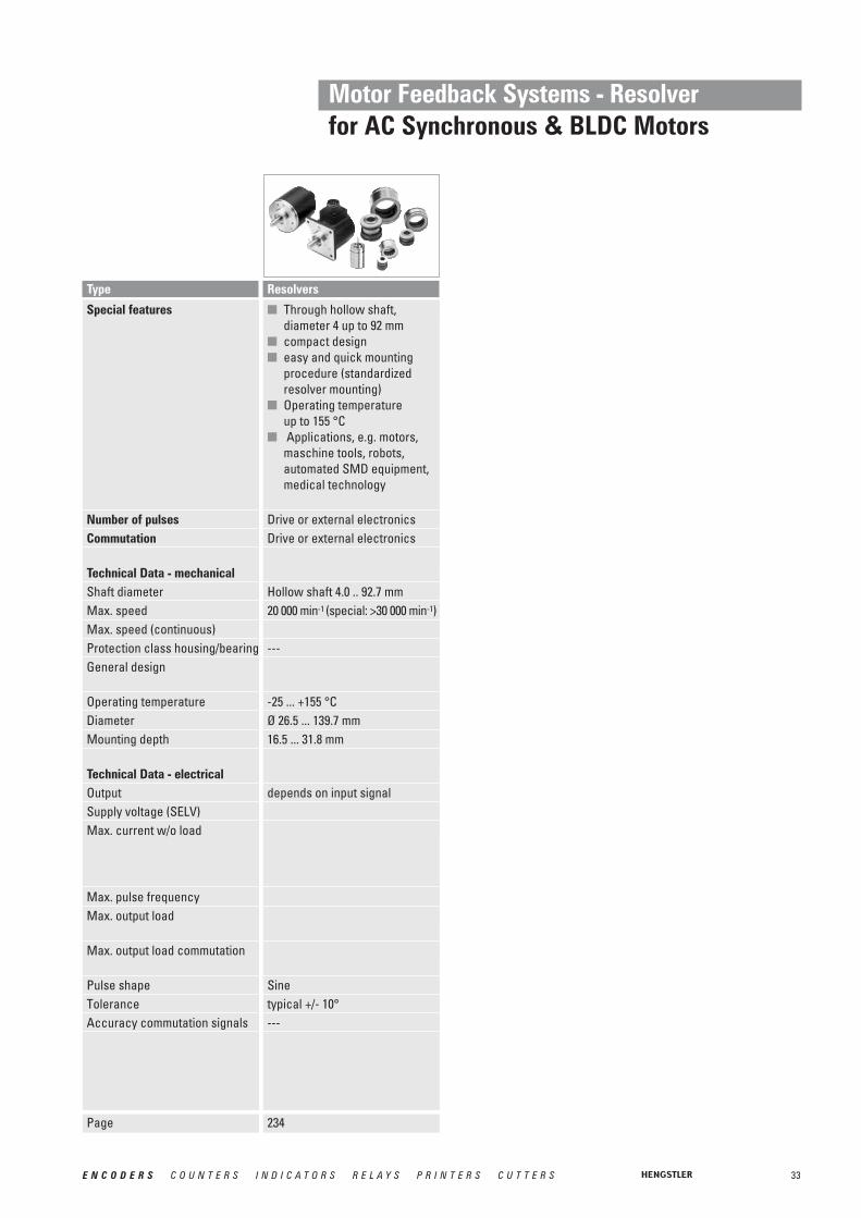
■ through hollow shaft■ shaft diameters 15 to 42 mm■ external diameter only 76 mm■ simple installation with
clamping ring front or rear■ operating temperature
up to 100 °C■ applications e.g.
motors, printing machines, elevators
1 ... 10 000
Clamping ring front or rearstator coupling(hubshaft with tether)Hollow shaft 15 ... 42 mm6 000 min-1 (depends on version)3 ... 10 Ncm (depends on version)IP50/40 (Option: IP65/64)as per DIN EN 61010, protectionclass III, Contamination level 2,over voltage class II-25 ... +100 °CCable radialØ 76 mm320 ... 580 g(depends on version)
RS 422 / push-pull /push-pull complementaryDC 5 V / DC 10 - 30 V60 mA (DC 5 V), 60 mA (DC 10 V),35 mA (DC 24 V)300 kHz (RS 422)200 kHz (push-pull)RS 422: ±30 mApush-pull with short circuitprotection: 30 mA (DC 10 - 30 V)NPN-O.C. 5 mASquare wave1 : 1
■ Incremental Output■ 30...45 mm hollow shaft ■ Rugged mechanical design■ Unbreakable disc■ Integrated diagnostic system■ Wide voltage range
DC 5 … 30 V
1024, 2048, 4096other number of pulses on request
(preliminary)Keyway, set screwSpring tether (single, double)
3600 min-1 (IP50), 1500 min-1 (IP64)
IP50, IP64as per DIN EN 61010, protectionclass III, Contamination level 2,over voltage class II-20 ... +70 °CSub-D 15p. / cable, radial
1 000 g
(preliminary)RS 422 / push-pull /push-pull complementaryDC 5 V ±10% or DC 5 - 30 V60 mA (DC 5 V), 60 mA (DC 10 V),35 mA (DC 24 V)600 kHz (RS 422)200 kHz (push-pull)RS 422: ±30 mApush-pull with short circuitprotection: 40 mA (DC 5 - 30 V)NPN-O.C. 5 mASquare wave1 : 1
Type RI 76 TD RI 80-E
Page 74 78

10 E N C O D E R S C O U N T E R S I N D I C A T O R S R E L A Y S P R I N T E R S C U T T E R S
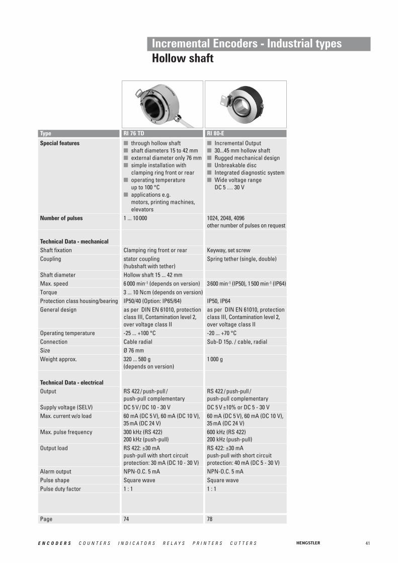
Incremental Encoders - Economy types
Special features
Number of pulses
Technical Data - mechanicalAbsolute max. shaft load
Moment of inertiaOperating temperatureStorage temperatureRelative humidityConnection
Technical Data - electricalCodePhasingSymmetryIndex pulse widthSupply voltageSupply voltageStanndby currentOutput signals
Ouput current
Max. pulse frequencyPulse shapePulse duty factor
■ Provides digital control inputs from operators´s panel
■ Bidirectional squarewave signal outputs
■ Up to 512 increments■ Continuous and reversible
rotation■ Noncontacting■ Operating temperature
-40 ... 100 °C
100 ... 512
1/8" Shaft: 4 N axial, 27 N radial1/4" Shaft: 4 N axial, 4 N radial0.20 gcm2
-40 ... +100 °C-50 ... +125 °C90 %, non-condensingPC9: 10 pole header,
(Accessory: 30 cm ribbon cable with connector)
PC9S: 5 pole header,(Accessory: 30 cm cable with connector)
Inkremental, optical90° ±18° electrical180° ±18° electrical90° ±36° electricalDC 5 V ±10 %10 mA, typicalmax. 50 μA (PC9 only)min. 2.5 V high (VOH)max. 0.5 V low (VOL)PC9: 3 mA sink/source
(25 °C), 2 mA (100 °C)PC9S: 6 mA sink/source
(25 °C), 4 mA (100 °C)200 kHzSquare wave1:1
Type PC 9 / PC 9S
Page 81

11E N C O D E R S C O U N T E R S I N D I C A T O R S R E L A Y S P R I N T E R S C U T T E R S
■ economy encoder■ high mechanical life■ applications e.g.
small motors, graphicmachines, desktop robots, wood working machines
5 ... 3 600
R = pilot flange6 mmradial 10 N, axial 5 N10 000 min-1
IP50/40as per DIN VDE 0160, protection class III-10° ... +70 °CCable radialØ 40 mm60 g
push-pull
DC 5 V or DC 10 - 30 V40 mA (DC 5 V), 30 mA (DC 24 V)300 kHz (DC 5 V)200 kHz (DC 10 - 30 V)
push-pull with short circuitprotection: 10 mA (DC 5 V),30 mA (DC 10 - 30 V)NPN-O.C. 5 mASquare wave1 : 1
Incremental Encoders - Economy types
Special features
Number of pulses
Technical Data - mechanicalFlangeShaft diameterAbsolute max. shaft loadAbsolute max. speedTorqueProtection class housing/bearingGeneral design
Operating temperatureConnectionSizeWeight approx.
Technical Data - electricalOutput
Supply voltage (SELV)Max. current w/o loadMax. pulse frequency
Output load
Alarm outputPulse shapePulse duty factor
■ economy encoder for small devices
■ long life due to ball bearings■ low torque■ application e.g.
laboratory devices, fitness machines, crimping machines, tampon printing machines, small grinding machines
5 ... 1 500
R = pilot flange5 mm / 6 mmradial 10 N, axial 5 N6 000 min-1
≤ 0.05 NcmIP50/40as per DIN VDE 0160, protection class III-10° ... +60 °CCable radial / axialØ 30 mm50 g
push-pull
DC 5 V or DC 10 - 30 V40 mA (DC 5 V), 30 mA (DC 24 V)300 kHz (DC 5 V)200 kHz (DC 10 - 30 V)
push-pull with short circuitprotection: 10 mA (DC 5 V),30 mA (DC 10 - 30 V)NPN-O.C. 5 mASquare wave1 : 1
■ encoder for universal mounting due to front or rear fixing
■ long life due to ball bearings■ low torque■ applications e.g.
small motors, laboratory devices, labelling devices, plotters, length measuring machines
5 ... 1 024
Q = square flange 6 mmradial 10 N, axial 5 N10 000 min-1
≤ 0.2 NcmIP50/40as per DIN VDE 0160, protection class III-10° ... +60 °CCable radial39 x 39 mm60 g
push-pull
DC 5 V or DC 10 - 30 V40 mA (DC 5 V), 30 mA (DC 24 V)300 kHz (DC 5 V)200 kHz (DC 10 - 30 V)
push-pull with short circuitprotection: 10 mA (DC 5 V),30 mA (DC 10 - 30 V)NPN-O.C. 5 mASquare wave1 : 1
Type RI 32 RI 38
Page 84 88
RI 41
86

12 E N C O D E R S C O U N T E R S I N D I C A T O R S R E L A Y S P R I N T E R S C U T T E R S
Incremental Encoders - Economy types
Special features
Number of pulses
Technical Data - mechanicalFlangeShaft diameterAbsolute max. shaft loadAbsolute max. speedTorqueProtection class housing/bearingGeneral design
Operating temperatureConnectionSizeWeight approx.
Technical Data - electricalOutput
Supply voltage (SELV)Max. current w/o loadMax. pulse frequency
Output load
Alarm outputPulse shapePulse duty factor
■ economy encoder■ high protection IP65■ push-pull or NPN-O.C.■ applications, e.g.
textile machinery
5 ... 1 024
R = pilot flange6 mmradial 10 N, axial 5 N10 000 min-1
≤ 1 NcmIP65/64as per DIN VDE 0160, protection class III0° ... +60 °CCable axialØ 40 mm75 g
push-pull / push-pull complementary / NPN-O.C.DC 5 V / DC 10 - 30 V / DC 10 - 24 V40 mA (DC 5 V), 30 mA (DC 24 V)300 kHz (DC 5 V)200 kHz (DC 10 - 30 V)50 kHz (DC 10 - 24 V)push-pull with short circuitprotection: 10 mA (DC 5 V),30 mA (DC 10 - 30 V)NPN-O.C. 5 mASquare wave1 : 1
Type RI 42
Page 90

13E N C O D E R S C O U N T E R S I N D I C A T O R S R E L A Y S P R I N T E R S C U T T E R S
Incremental EX and Stainless Steel Encoders
Special features
Number of pulses
Technical Data - mechanicalFlangeShaft diameterMax. shaft load Max. speedTorqueProtection class housing/bearingGeneral design
Operating temperatureConnectionSize
Weight approx.
Technical Data - electricalOutput
Supply voltage (SELV)Max. current w/o load
Max. pulse frequency
Output load
Alarm outputPulse shapePulse duty factorPulse width error
■ stainless steel encoder with high degree of protection
■ high corrosion resistance■ suitable for use in food
production■ applications e.g.
packaging machinery, filling plants, washing systems, mixing machines
1 ... 10 000
Q = square flange9.52 mm / 10 mmradial 60 N, axial 40 N10 000 min-1
≤ 0.5 NcmIP67/67as per DIN VDE 0160, protection class III-10 ... + 70 °CCable radialØ 58 mm, square flange = 63.5 mm620 g
RS 422 / push-pull /push-pull complementaryDC 5 V / DC 10 - 30 V40 mA (DC 5 V), 30 mA (DC 24 V), 60 mA (DC 10 V)300 kHz (RS 422)200 kHz (push-pull)RS 422: ±30 mApush-pull with short circuitprotection: 30 mA (DC 10 - 30 V)NPN-O.C. 5 mASquare wave1 : 1± max. 25° electrical
■ explosion-proof according toEX II 2 G/D EEX d IIC T6/T4
■ highest operating safety ■ applications e.g.
lacquering lines, surface processing machines, filling plants, mixing machines, silo systems
1 ... 10 000
K = clamping flange10 mmradial 100 N,axial 40 N6 000 min-1 (T6), 10 000 min-1 (T4)≤ 0.5 NcmIP65/64as per DIN VDE 0160, protection class III-10 ... + 40 °CCable axialØ 70 mm
1400 g
RS 422 / push-pull /push-pull complementaryDC 5 V / DC 10 - 30 V40 mA (DC 5 V), 30 mA (DC 24 V), 60 mA (DC 10 V)300 kHz (RS 422)200 kHz (push-pull)RS 422: ±30 mApush-pull with short circuitprotection:30 mA (DC 10 - 30 V)NPN-O.C. 5 mASquare wave1 : 1± max. 25° electrical
Type RI 59RX 70-TI / RX 71-TI (Stainless)
Page 9592

14 E N C O D E R S C O U N T E R S I N D I C A T O R S R E L A Y S P R I N T E R S C U T T E R S
Incremental Sine-Wave Enoders
Type RIS 58-H
Page 9997
Special features
Number of pulses
Technical Data - mechanicalShaft diameterAbsolute max. shaft loadBalance tolerances Max. speedTorqueProtection (EN 60529)
General designOperating temperatureVibration (IEC 68-2-6)Shock (IEC 68-2-27)Material housingConnection
SizeWeight approx.
Technical Data - electricalSupply voltage (SELV)Max. current w/o loadIncremental signals A, B
Absolute accuracyRepeatability
Max. frequencyReference signal: R
■ Harmonic distortion less than 1 %
■ Extended temperature range, -40° up to +100 °C
■ 500 kHz sine-wave incremental signal frequency response
■ Self-monitoring and error compensation
■ Secure against short-circuit and overload
1 000, 1 024, 2 048( other numberof pulses on request)
10 mm, 12 mm hollow shaft
axial ±1.5 mm, radial ±0.2 mm12 000 min -1
≤ 1 NcmBearing IP64, Housing IP65as per DIN EN 61010-1-40 ... +100 °C≤ 100 m/s2
≤ 1 000 m/s2
AluminiumCable axial or radialConin axial or radialØ 58 mm270 g
DC 5 V / ±10 %120 mASine - Cosine 1 Vpp±35“±7“500 kHz> 0,4 V (1 pulse / turn)
■ Harmonic distortion less than 1 %
■ Extended temperature range, -40° up to +100 °C
■ 500 kHz sine-wave incremental signal frequency response
■ Self-monitoring and error compensation
■ Secure against short-circuit and overload
1 000, 1 024, 2 048, 2 500 (othernumber of pulses on request)
6 mmradial 60 N/ axial 40 N
12 000 min -1
≤ 1 NcmBearing IP64, Housing IP65as per DIN EN 61010-1-40 ... +100 °C≤ 100 m/s2
≤ 1 000 m/s2
AluminiumCable axial or radialConin axial or radialØ 58 mm265 g
DC 5 V / ±10 %120 mASine - Cosine 1 Vpp±35“±7“500 kHz> 0,4 V (1 pulse / turn)
RIS 58-0

15E N C O D E R S C O U N T E R S I N D I C A T O R S R E L A Y S P R I N T E R S C U T T E R S
Type
(preliminary)37.5 mmIP64 IP64 pilot flange6 mmContinuous: 10 000 min-1,Short term: 12 000 min-1
0,01 Nm2.5 x 10-6 kgm2
± 0.5 mm/ ± 0.05 mm1 000 m/s2 (6 ms)
100 m/s2 (10 ... 2 000 Hz)
-25 … +100 °C-15 … +85 °C (because of packing)80 g / 130 g
(preliminary)DC 5 V, -5 % / + 10 %50 mA / 100 mABiSS or Standard SSIClock and Data / RS422Gray or Binary13 Bit ... max. 17 Bit12 BitSine - Cosine 1 Vpp2048500 kHz
Alarm bit (SSI option), warning bit and alarm bit (BiSS)Cable axial or radial
AC36 - BiSS / SSI
Absolute Shaft Encoders - ACURO industryAC 36 - BiSS / SSISpecial Features■Compact design for single or multiturn■ Interfaces: standard SSI, expanded SSI mode or BiSS■Use of sine / cosine signals for fast control tasks possible
Page 109
Technical Data - mechanicalHousing diameterProtection class shaft inputProtection class housingFlangeShaft diameterMax. speed
Starting TorqueMoment of inertiaSpring tether (hollow shaft)Tolerance axial / radialShock resistanceDIN EN 60068-2-27Vibration resistanceDIN EN 60068-2-6Operating temperatureStorage temperatureWeight approx. ST/MT
Technical Data - electricalSupply voltageMax. current w/o load ST/MTInterfaceLines / DrivesOutput codeResolution singleturnResolution multiturnIncremental signals
Number of pulses3 dB limiting frequency
Alarm output
Connection

16 E N C O D E R S C O U N T E R S I N D I C A T O R S R E L A Y S P R I N T E R S C U T T E R S
Technical Data - mechanicalHousing diameterProtection class shaft inputProtection class housingFlange
Shaft diameter
Max. speed
Shaft loadOperating temperatureWeight approx. ST/MT
Technical Data - electricalSupply voltage
Max. current w/o load ST/MTInterfaceResolution singleturn
Resolution multi turnOptional incremental signals
Number of pulsesAbsolute accuracyRepeat accuracy
Parameterization
Control input
Reset keyAlarm output
Status LEDConnection
Type
58 mmIP64 or IP67IP64 (IP67 optional)Synchro flange, clamping flange, hubshaft with tether, squareflangeSolid shaft 6 mm, 10 mm;Hub shaft 10 mm, 12 mmContinuous: 10 000 min-1,Short term: 12 000 min-1
axial 40 N / radial 60 N-40 … 100 °C260 g / 310 g
DC 5 V, -5 % / + 10 % or DC 10 - 30 V50 mA / 100 mABiSS or Standard SSI10-17 Bit,Gray Excess: 360, 720 steps12 BitSine - Cosine 1 Vpp2048±35“±7“Code type, direction of rotation,warning, alarm
Latch via parameterizationAlarm bit (SSI option), warning bit and alarm bit (BiSS)Green = OK.; red = alarmCable axial or radialConin axial or radialM12, 8 pole
Direction
AC 58 - BiSS / SSI
58 mmIP64 or IP67IP64 (IP67 optional)Synchro flange, clamping flange, hubshaft with tether, squareflangeSolid shaft 6 mm, 10 mm;Hub shaft 10 mm, 12 mmContinuous: 10 000 min-1,Short term: 12 000 min-1
axial 40 N / radial 60 N-40 … 100 °C350 g / 400 g
DC 10 - 30 V
200 mA / 300 mAParallel10-14 Bit,Gray Excess: 360, 720 steps12 Bit
ST: , , MT: Tristateonly with MTNPN o.c. max. 5 mA
Green = OK.; red = alarmCable axial or radial17 pole Conin axial or radial 37 pole Sub-D
TristateDirectionLatch
AC 58 - Parallel
Absolute Shaft Encoders - ACURO industryAC 58 - BiSS / SSI, ParallelSpecial Features■Compact design for single or multiturn■Aids for start-up and operation: diagnostic LED, preset key with optical response■ Interfaces: standard SSI, expanded SSI mode or BiSS■Use of sine / cosine signals for fast control tasks possible
Page 113 118

17E N C O D E R S C O U N T E R S I N D I C A T O R S R E L A Y S P R I N T E R S C U T T E R S
Technical Data - mechanicalHousing diameterProtection class shaft inputProtection class housing
Flange
Shaft diameter
Max. speed
Shaft loadOperating temperatureWeight approx. ST/MT
Technical Data - electricalSupply voltageMax. current w/o load ST/MTInterface
Profile / Protocol
ProgrammableOutput codeTransfer mode
Baud rate
Resolution singleturn Resolution multiturnIntegrated special functions
Connection
Type
58 mmIP64 or IP67IP67
Synchro flange, clamping flange, hubshaft with tether, squareflangeSolid shaft 6 mm, 10 mm;Hub shaft 10 mm, 12 mmContinuous: 10 000 min-1,Short term: 12 000 min-1
axial 40 N / radial 60 N-40 … 85 °C350 g / 400 g
DC 10 - 30 V 220 mA / 250 mA RS 485
Profibus DP with encoder profileClass C2 (parameterizable)Resolution, preset, directionBinary
is automatically set within a rangeof 9,6 KBaud through 12 MBaud 10-14 Bit12 Bitspeed, acceleration, operating timeBus cover with: •• 3 M12 connectors •• 3 sealed cable exits•• double conin 12 pole
radial cw•• 4 pole M12 f. “tico” display
+ 2 sealed cable exits
AC 58 - Profibus
58 mmIP64 or IP67Bus cover: IP67Conin, cable: IP64 (IP67 optional)Synchro flange, clamping flange, hubshaft with tether, squareflangeSolid shaft 6 mm, 10 mm;Hub shaft 10 mm, 12 mmContinuous: 10 000 min-1,Short term: 12 000 min-1
axial 40 N / radial 60 N-40 … 85 °C350 g / 400 g
DC 10 - 30 V 220 mA / 250 mA CAN High-Speed according ISO/DIS 11898CANopen accord. DS 301 with encoder profile DSP 406Resolution, preset, directionBinaryPoll mode (only on request),Change of State (automatic ifvalue changes), cyclical withadjustable cycle timerset via DIP switch within a rangeof 10 trough 1000 Kbit/s10-14 Bit12 Bitspeed, acceleration, round axis,limit valuesBus cover with: •• 3 sealed cable exits•• double conin 9 pole
radial cwCable radial or axial Conin radial or axial, cw or ccw
AC 58 - CANopen
58 mmIP64 or IP67Bus cover: IP67Conin, cable: IP64 (IP67 optional)Synchro flange, clamping flange, hubshaft with tether, squareflangeSolid shaft 6 mm, 10 mm;Hub shaft 10 mm, 12 mmContinuous: 10 000 min-1,Short term: 12 000 min-1
axial 40 N / radial 60 N-40 … 85 °C350 g / 400 g
DC 10 - 30 V220 mA / 250 mA CAN High-Speed according ISO/DIS 11898CAN 2.0 A
Direction, limit valuesBinaryPoll mode (only on request),Change of State (automatic ifvalue changes), cyclical withadjustable cycle timerset via DIP switch within a rangeof 10 trough 1000 Kbit/s10-14 Bit12 Bit
Bus cover with: •• 3 sealed cable exits•• double conin connectors
9 pole radial cwCable radial or axialConin radial or axial, cw or ccw
AC 58 - CANLayer 2
Absolute Shaft Encoders - ACURO industryAC 58 with Fieldbus InterfacesSpecial Features■Overall length: 63 mm for singleturn, 73 mm for multiturn, including bus cover■The complete bus specific electronics is integrated in the connection cover■Option: Display "tico"■Diagnostic LEDs in the bus cover
Page 123 127 130

18 E N C O D E R S C O U N T E R S I N D I C A T O R S R E L A Y S P R I N T E R S C U T T E R S
Technical Data - mechanicalHousing diameterProtection class shaft inputProtection class housing
Flange
Shaft diameter
Max. speed
Shaft loadOperating temperatureWeight approx. ST/MT
Technical Data - electricalSupply voltageMax. current w/o load ST/MTInterface
Profile / Protocol
Programmable
Output codeTransfer mode
Baud rate
Resolution singleturn Resolution multiturnConnection
Type
58 mmIP64 or IP67IP67
Synchro flange, clamping flange, hubshaft with tether, squareflangeSolid shaft 6 mm, 10 mm;Hub shaft 10 mm, 12 mmContinuous: 10 000 min-1,Short term: 12 000 min-1
axial 40 N / radial 60 N-40 … 85 °C350 g / 400 g
DC 10 - 30 V220 mA / 250 mA CAN High-Speed according ISO/DIS 11898, CAN-Specification 2.0 A (11-Bit-Identifier)DeviceNet nach Rev. 2.0, programmable encoderResolution, preset, direction
BinaryPoll mode (only on request),Change of State (automatic ifvalue changes), cyclical withadjustable cycle timerset via DIP switches to125, 250, 500 KBaud10-14 Bit12 BitBus cover with: •• 2 sealed cable exits•• 4 pole M12 f. “tico” display
+ 2 sealed cable exits •• 5 pole M12
AC 58 - DeviceNet
58 mmIP64 or IP67Bus cover: IP67Cable: IP64 (IP67 optional)Synchro flange, clamping flange, hubshaft with tether, squareflangeSolid shaft 6 mm, 10 mm;Hub shaft 10 mm, 12 mmContinuous: 10 000 min-1,Short term: 12 000 min-1
axial 40 N / radial 60 N-40 … 70 °C350 g / 400 g
DC 10-30 V220 mA / 250 mA Remote installation busInterbus, ENCOM Profile K3 (parameterizable), K2K3 = ID-Code 37K2 = ID-Code 36Direction, scaling factor,preset, offset32 Bit binary
500 KBaud according ENCOM
10-12 Bit 12 BitBus cover with: •• 3 sealed cable exits•• 4 pole M12 f. “tico” Display
+ 2 sealed cable exits•• double conin 9 poleCable 12 pole, radial and axial
AC 58 - Interbus
58 mmIP64 or IP67IP64
Synchro flange, clamping flange, hubshaft with tether, squareflangeSolid shaft 6 mm, 10 mm;Hub shaft 10 mm, 12 mmContinuous: 10 000 min-1,Short term: 12 000 min-1
axial 40 N / radial 60 N-10 … 60 °C260 g / 310 g
DC 10-30 V220 mARS485
SUCOnet-K1 or Hengstler-G1-Protocol
Binary
10 - 13 Bit12 BitCable axial/ radial
AC 58 - SUCOnet
Absolute Shaft Encoders - ACURO industryAC 58 with Fieldbus InterfacesSpecial Features■Overall length: 63 mm for singleturn, 73 mm for multiturn, including bus cover■The complete bus specific electronics is integrated in the connection cover■Option: Display "tico"■DiagnosticLEDs in the bus cover
Page 133 136 140

19E N C O D E R S C O U N T E R S I N D I C A T O R S R E L A Y S P R I N T E R S C U T T E R S
Technical Data - mechanicalHousing diameterProtection class shaft inputProtection class housingFlange
Shaft diameter
Max. speed
Shaft loadOperating temperatureWeight approx. ST/MT
Technical Data - electricalSupply voltageMax. current w/o loadInterface Resolution singleturn Resolution multiturnParameterization
Control inputAlarm outputStatus LEDConnection
Type
58 mmIP64 or IP67IP64 (IP67 optional)Synchro flange, clamping flange, hubshaft with tether, squareflangeSolid shaft 6 mm, 10 mm;Hub shaft 10 mm, 12 mmContinuous: 10 000 min-1,Short term: 12 000 min-1
axial 40 N / radial 60 N-40 … 70 °C260 g / 310 g
DC 10 - 30 Vmax. 250 mASSI programmable10 - 17 Bit12 Bitresolution, code type, sense ofrotation, output format, warning,alarmDirection, Preset 1, Preset 2Alarm bitGreen = ok.; red = alarmCable radial or axialConin radial or axial, ccw
AC 58 - SSI Programmable
Absolute Shaft Encoders - ACURO industryAC 58 - SSI programmableSpecial Features■Compact design: 59mm length for single or multiturn■Aids for start-up and operation: diagnostic LED, preset key with optical response■Parameterization: resolution, code type, sense of rotation, output format, warning, alarm■Parameters can be stored in a non-volatile memory
Page 142

20 E N C O D E R S C O U N T E R S I N D I C A T O R S R E L A Y S P R I N T E R S C U T T E R S
Technical Data - mechanicalHousing diameterShaft diameterProtection class shaftProtection class housingFlangeMax. speed
Spring tether (hollow shaft)Tolerance axial / radialVibration resistance (IEC 68-2-6)Shock resistance (IEC 68-2-27)Operating temperatureStorage temperatureWeight approx.
Technical Data - electricalSupply voltage
Max. current w/o load ST/MTLines/ DrivesOutput codeResolution singleturnIncremental signals
No. of increments3 dB limiting frequencyAbsolute accuracyRepeatability
Alarm output
Connection
Type
(preliminary)110 mm up to 50 mm IP50 or IP64IP50 or IP64Hollowshaft with tetherIP50: 3600 min-1
IP64: 1500 min-1
± 0.5 mm / ± 0.05 mm
100 m/ s2 (10 - 500 Hz)1000 m/ s2 (6 ms) -20 ...+70°C -50 ...+80°C 1000 g
(preliminary)DC 5 V (–5 %/ +10 %) or DC 10-30 V120 mAClock and Data/ RS422Binary or Gray10 - 17 BitSine - Cosine 1 Vpp4096500 kHz± 35“± 7“alarm bit (SSI), warning bit and alarm bit (BiSS)Cable radialCable with Conin-Coupling
AC 110 - BiSS / SSI
Absolute Shaft Encoders - ACURO industryAC 110 - BiSS / SSISpecial Features■Hollow shaft up to 50 mm■Singleturn up to bis 17 Bit
Page 151

21E N C O D E R S C O U N T E R S I N D I C A T O R S R E L A Y S P R I N T E R S C U T T E R S
Absolute Shaft EncodersStainless Steel / Explosion-Proof
Special Features
Technical Data – mechanicalHousing diameterShaft diameterFlangeMax. speed
TorqueMoment or inertia Max. shaft loadVibration proof (IEC 68-2-6)Shock resistance (IEC 68-2-27)Operating temperature
Storage temperatureMaterial Shaft/ Housing
Weight approx.
Technical Data – electrical
■ ATEX certification for gas anddust explosion proof
■ EX-classification: Ex II 2 G/D E Ex d II C T4/T6
■ Same electrical performance as ACURO industry
■ Protection class up to IP67■ Diameter only 70 mm ■ Robust design■ Available with stainless steel■ Resolution up to 29 Bit
(17 Bit ST, 12 Bit MT)■ Applications:
enamelling production line,petro chemistry, bottling machines, mixers, silo works, mills
■ Interfaces: SSI, SSI programmable, Profibus, CANopen
70 mm10 mmClamping flange6 000 min -1 (T6)10 000 min -1 (T4)≤ 1 Ncmapprox. 20 gcm2
axial 40 N/ radial 100 N100 m/ s2 (10 - 500 Hz)1000 m/ s2 (6 ms)-40 ... +60 °C (T4)-40 ... +40 °C (T6)
-25 ... +80 °CAluminium (AX 70)Stainless steel (AX 71)1 000 g (AX 70), 1 900 g (AX 71)
The electrical data dependon the type of interface. Please refer to chapter
“AX 70 / AX 71”.
Type AX 70/ AX 71 (Stainless)
Page 161154
■ Compact design■ Protection class IP67■ High corrosion resistance■ Robust design■ Resolution up to 29 Bit
(17 Bit ST, 12 Bit MT)■ Connection with cable or
with bus terminal box■ Applications:
- Packaging machine for food and beverage
- Ship equipment (e.g. cranes, winches, cable laying ships)
- Offshore - Applications
10 mmSquare flange 63.5 x 63.5 mmShort term: 10 000 min-1
Continuous: 6 000 min-1
< 1 Ncmapprox. 20 gcm2
axial 40 N/ radial 60 N100 m/ s2 (10 - 500 Hz)1000 m/ s2 (6 ms)SSI, BiSS, Parallel: -40...+100°C SSI-P, Interbus: -40...+70°C Profibus, CANopen, CANlayer2,DeviceNet: -40...+ 85°C40...+ 85°C Stainless steel
AC 59 with 1.5 m cable: 700 gAC 61 with 1.5 m cable: 980 gAC 61 with bus cover (MT): 1 180 g
The electrical data dependon the type of interface.
Please refer to the specific interface chapter.
AC 59/61

22 E N C O D E R S C O U N T E R S I N D I C A T O R S R E L A Y S P R I N T E R S C U T T E R S
Motor Feedback Systems - Kit Encodersfor Miniature DC and Stepper Motors
Special features
Number of pulsesCommutation
Technical Data - mechanicalShaft diameterMax. speedProtection class housing/bearingOperating temperatureDiameterMounting depth
Technical Data - electricalOutputSupply voltage (SELV)Max. current w/o load
Max. pulse frequencyMax. output load
Pulse shapePhasingSymmetry
■ ideal for position and speedsensing in small machines and actuators
■ 200 kHz operating frequency■ resolution to 512 lines/rev
100 ... 512None
Hollow shaft Ø 1.5 ... 4.0 mm12 000 min-1
----40 ... + 100 °C22.0 mm14.8 mm
TTLDC 5 V ±10 %10 mA, typ.
200 kHz3 mA (25°C),2 mA (100°C)Square wave90°±18° electrical180°±18° electrical
■ ideal economical feedback device for servo and stepper motors
■ short axial length and compact 1.5 inch diameter
■ easy "snap-on" installation■ high resolution to
1024 lines/rev and 200 kHz bandwidth
■ drop-in replacement for HP 5540
200 ... 1 024None
Hollow shaft Ø 3.0 ... 8.0 mm12 000 min-1
----40 ... + 100 °C38.0 mm17.2 mm
TTLDC 5 V ±10 %10 mA, typ.
200 kHz6mA (25°C)4 mA (100°C)Square wave90°±18° electrical180°±18° electrical
Type M 9 M 14
Page 183180
■ ideal for position and speed sensing in small machines and actuators
■ low power standby mode is ideal for battery powered devices
■ 200 kHz operating frequency■ resolution to 512 lines/rev
100 ... 512None
Hollow shaft Ø 1.5 ... 4.0 mm12 000 min-1
----40 ... + 100 °C22.0 mm20.0 mm
TTLDC 5 V ±10 %10 mA, typ.Standby current: max. 50 μA200 kHz3 mA (25°C),2 mA (100°C)Square wave90°±18° electrical180°±18° electrical
E 9
186

23E N C O D E R S C O U N T E R S I N D I C A T O R S R E L A Y S P R I N T E R S C U T T E R S
Motor Feedback Systems - Hollow shaft Encodersfor Asynchronous & DC Motors
Special features
Number of pulsesCommutation
Technical Data - mechanicalShaft diameterMax. speedMax. speed (continuous)Protection class housing/bearingGeneral design
Operating temperatureDiameterMounting depth
Technical Data - electricalOutput
Supply voltage (SELV)Max. current w/o load
Max. pulse frequency
Max. output load
Pulse shape
■ direct mounting without coupling
■ flexible hollow shaft concept up to 14 mm
■ through hollow shaft or as end shaft (blind shaft)
■ easy mounting procedure with clamping flange or fastening thread
■ short mounting depth of 33 mm■ operating temperature
up to 80 °C ■ Fixing of the flage with a
stator coupling or cylindric pin■ applications, e.g.
positioning drives, motors1 ... 5 000None
Hollow shaft 10 mm / 12 mm / 14 mm6 000 min-1
IP65/64as per DIN VDE 0160,protection class III-10 ... +70 °C58 mm33 mm .. 50.5 mm(depends on version)
RS 422 / push-pull / push-pullcomplementaryDC 5 V / DC 10 - 30 V40 mA (DC 5 V), 30 mA (DC 24 V),60 mA (DC 10 V)300 kHz (RS 422)200 kHz (push-pull)RS 422: ±30 mApush-pull with short circuitprotection: 30 mA (DC 10 - 30 V)Square wave
■ direct mounting without coupling
■ flexible hollow shaft concept up to 14 mm
■ through hollow shaft or as end shaft (blind shaft)
■ easy mounting procedure with clamping flange or fastening thread
■ short mounting depth of 33 mm■ operating temperature up to
100 °C■ Fixing of the flage with a
stator coupling or cylindric pin■ applications, e.g.
positioning drives, motors4 ... 2 500None
Hollow shaft 10 mm / 12 mm / 14 mm6 000 min-1
IP65/64as per DIN VDE 0160,protection class III-25 .. +100 °C58 mm33 mm .. 50.5 mm (depends on version)
RS 422 / push-pull / push-pullcomplementaryDC 5 V / DC 10 - 30 V40 mA (DC 5 V), 30 mA (DC 24 V),60 mA (DC 10 V)300 kHz (RS 422)200 kHz (push-pull)RS 422: ±30 mApush-pull with short circuitprotection: 30 mA (DC 10 - 30 V)Square wave
Type RI 58-D RI 58TD
Page 6862
■ miniature industry encoder for high numbers of pulses
■ short mounting depth■ easy mounting procedure■ applications, e.g.
motors, machine tools, packaging machines, robots, automated SMD equipment
5 ... 3 600None
Hollow shaft 4 / 6 / 8 / 10 mm10 000 min-1
IP64/64as per DIN VDE 0160,protection class III-10 ... +70 °C36 mm39 mm
RS 422 / push-pull / push-pullcomplementaryDC 5 V / DC 10 - 30 V40 mA (DC 5 V), 30 mA (DC 24 V),60 mA (DC 10 V)300 kHz (RS 422)200 kHz (push-pull)RS 422: ±30 mApush-pull with short circuitprotection: 30 mA (DC 10 - 30 V)Square wave
RI 36-H
68

24 E N C O D E R S C O U N T E R S I N D I C A T O R S R E L A Y S P R I N T E R S C U T T E R S
Motor Feedback Systems - Hollow shaft Encodersfor Asynchronous & DC Motors
Special features
Number of pulses
Commutation
Technical Data - mechanicalShaft fixationCoupling
Shaft diameterMax. speedProtection class housing/bearingGeneral design
Operating temperatureConnectionDiameterWeight
Technical Data - electricalOutput
Supply voltage (SELV)Max. current w/o load
Max. pulse frequency
Max. output load
Alarm outputPulse shapePulse duty factor
Type
Page 74
■ through hollow shaft■ shaft diameters 15 to 42 mm■ external diameter only 76 mm■ simple installation with
clamping ring front or rear■ operating temperature
up to 100 °C■ applications e.g.
motors, printing machines, elevators
1 ... 10 000
None
Clamping ring front or rearstator coupling(hubshaft with tether)Hollow shaft 15 ... 42 mm6 000 min-1 (depends on version)IP50/40 (Option: IP65/64)as per DIN EN 61010, protectionclass III, Contamination level 2,over voltage class II-25 ... +100 °CCable radial76 mm320 ... 580 g (depends on version)
RS 422 / push-pull /push-pull complementaryDC 5 V / DC 10 - 30 V60 mA (DC 5 V), 60 mA (DC 10 V),35 mA (DC 24 V)300 kHz (RS 422)200 kHz (push-pull)RS 422: ±30 mApush-pull with short circuitprotection: 30 mA (DC 10 - 30 V)NPN-O.C. 5 mASquare wave1 : 1
RI 76TD
■ incremental Output■ 30...45 mm hollow shaft ■ rugged mechanical design■ unbreakable disc■ integrated diagnostic system■ wide voltage range
DC 5 … 30 V
1024, 2048, 4096other number of pulses on requestNone
Keyway, set screwSpring tether (single, double)
Hollow shaft 30 ... 45 mm3600 min-1 (IP50), 1500 min-1 (IP64)IP50, IP64as per DIN EN 61010, protectionclass III, Contamination level 2,over voltage class II-20 ... +70 °CSub-D 15p. / cable, radial
1 000 g
RS 422 / push-pull /push-pull complementaryDC 5 V ±10% or DC 5 - 30 V60 mA (DC 5 V), 60 mA (DC 10 V),35 mA (DC 24 V)600 kHz (RS 422)200 kHz (push-pull)RS 422: ±30 mApush-pull with short circuitprotection: 40 mA (DC 5 - 30 V)NPN-O.C. 5 mASquare wave1 : 1
RI 80-E
78

25E N C O D E R S C O U N T E R S I N D I C A T O R S R E L A Y S P R I N T E R S C U T T E R S
Motor Feedback Systems - Hollow shaft Encodersfor Asynchronous & DC Motors
Special features
Number of pulses
Technical Data - mechanicalShaft diameterBalance tolerances Max. speedTorqueProtection (EN 60529)
General designOperating temperatureVibration (IEC 68-2-6)Shock (IEC 68-2-27)Material housingConnection
SizeWeight approx.
Technical Data - electricalSupply voltage (SELV)Max. current w/o loadIncremental signals A, B
Absolute accuracyRepeatability
Max. output frequencyReference signal: R
Type
■ harmonic distortion less than 1 %
■ extended temperature range, -40° up to +100 °C
■ 500 kHz sine-wave incremental signal frequency response
■ self-monitoring and error compensation
■ secure against short-circuit and overload
1 000, 1 024, 2 048, 2 500, 5 000
10 mm, 12 mm hollow shaftaxial ±1.5 mm, radial ±0.2 mm12 000 min -1
≤ 1 NcmBearing IP64, Housing IP65as per DIN EN 61010-1-40 ... +100 °C≤ 100 m/s2
≤ 1 000 m/s2
AluminiumCable axial or radialConin axial or radialØ 58 mm270 g
DC 5 V / ±10 %120 mASine - Cosine 1 Vpp±35“±7“500 kHz> 0,4 V (1 pulse / turn)
RIS 58-H
Page 99

26 E N C O D E R S C O U N T E R S I N D I C A T O R S R E L A Y S P R I N T E R S C U T T E R S
Motor Feedback Systems - Hollow shaft Encodersfor Asynchronous & DC Motors
Technical Data - mechanicalHousing diameterShaft diameterProtection class shaft inputProtection class housingFlangeMax. speed
Shaft loadSpring tether (hollow shaft)Tolerance axial / radialShock resistance (IEC 68-2-27)Vibration resistance (IEC 68-2-6)Operating temperatureWeight approx. ST/MT
Technical Data - electricalSupply voltage
Max. current w/o load ST/MTInterfaceLines/ DrivesOutput codeLinearity
Resolution singleturn
Resolution multiturnOptional incremental signals
Number of pulses3 db limiting frequencyAbsolute accuracyRepeatability
Parameterization
Control inputReset keyAlarm output
Status LEDConnection
110 mm up to 50 mm IP50 or IP64IP50 or IP64Hollow shaft with tetherIP50: 3600 min-1
IP64: 1500 min-1
± 0.5 mm / ± 0.05 mm1000 m/ s2 (6 ms) 100 m/ s2 (10 - 500 Hz)-20 ...+70°C 1000 g
DC 5 V (–5 %/ +10 %) or DC 10-30 V120 mABiSS or Standard SSIClock and Data/ RS422Binary or Gray
10 - 17 Bit
only singleturnSine - Cosine 1 Vpp4096500 kHz± 35“± 7“Code type, sense of rotation,warning, alarm
Alarm bit (SSI option), warning bit and alarm bit (BiSS)
Cable radialCable with Conin-Coupling
Direction
Type AC 110 - BiSS / SSI
58 mmHub shaft 10 mm, 12 mmIP64 or IP67IP64 (IP67 optional)Hubshaft with tetherContinuous: 10 000 min-1,Short term: 12 000 min-1
axial 40 N / radial 60 N
± 1.5 mm/ ± 0.2 mm1 000 m/s2 (6 ms)100 m/s2 (10 ... 2 000 Hz)
-40 … 100 °C260 g / 310 g
DC 5 V, -5 % / + 10 % or DC 10 - 30 V50 mA / 100 mABiSS or Standard SSIClock and Data/ RS422Binary or Gray±1/2 LSB(± 1 LSB for resolution > 13 Bit)
10-17 Bit,Gray Excess: 360, 720 steps12 BitSine - Cosine 1 Vpp2048500 kHz±35“±7“Code type, sense of rotation,warning, alarm
Disable via parameterizationAlarm bit (SSI option), warning bit and alarm bit (BiSS)Green = OK.; red = alarmCable axial or radialConin axial or radialM12, 8 pole
Direction
AC 58 - BiSS / SSI
Page 113 151

27E N C O D E R S C O U N T E R S I N D I C A T O R S R E L A Y S P R I N T E R S C U T T E R S
Motor Feedback Systems - Comcodersfor AC Synchronous & BLDC Motors
Special features
Number of pulsesCommutation
Technical Data - mechanicalShaft diameterMax. speedMax. speed (continuous)Protection class housing/bearingGeneral design
Operating temperatureDiameterMounting depth
Technical Data - electricalOutputSupply voltage (SELV)Max. current w/o load
Max. pulse frequencyMax. output load
Max. output load commutation
Pulse shapePhasingSymmetryAccuracy commutation signals
■ through hollow shaft, diameter 6 ... 12.7 mm
■ output signals: A, B, N as incremental signals as well as 4, 6, 8, 10, 12 or 16 pole commutation signals
■ external diameter 53 mm (2.1‘’)■ mounting depth only 20 mm
(0.8‘’)■ max. speed up to 12 000 min-1
■ operating temperature up to 120°C
500 ... 2 0484, 6, 8, 10, 12 or 16 pole
Hollow shaft 6 ... 12.7 mm12 000 min-1
IP40/40 (with cover)
-40 ... +120 °C53 mm20.3 mm
NPN-O.C. / RS 422DC 5 V / DC 2 V ±10%Incremental: max. 100 mAIncremental + Commutation: 175 mA
200 kHzRS 422: ±40 mANPN-O.C. 16 mANPN-O.C. 16 mARS 422: ±40 mASquare wave90°±18° electrical180°±18° electrical±6 arc-mins. max.
Type M21
Page 196191
■ through hollow shaft, diameter 3.18 ... 10 mm
■ output signals: A, B, Nas incremental signals as well as 4, 6 or 8 pole commutation signals
■ external diameter 40 mm (1.5 ‘’)■ mounting depth only 28 mm
(1.1‘’)■ max. speed up to 12 000 min-1
■ operating temperature up to 120°C
200 ... 1 0244, 6 or 8 pole
Hollow shaft 3.18 ... 10 mm12 000 min-1
IP40/40
-40 ... +120 °C39.6 mm27.9 mm
NPN-O.C./ RS 422DC 5 V / DC 12 V ±10%Incremental: max. 100 mAIncremental + Commutation: 120 mA
200 kHzNPN-O.C. 16 mARS 422: ±40 mANPN-O.C. 16 mARS 422: ±40 mASquare wave90°±18° electrical180°±18° electrical±6 arc-mins. max.
M15

28 E N C O D E R S C O U N T E R S I N D I C A T O R S R E L A Y S P R I N T E R S C U T T E R S
Motor Feedback Systems - Comcodersfor AC Synchronous & BLDC Motors
Special features
Number of pulsesCommutation
Technical Data - mechanicalShaft diameterMax. speedMax. speed (continuous)Protection class housing/bearingGeneral design
Operating temperatureDiameterMounting depth
Technical Data - electricalOutputSupply voltage (SELV)Max. current w/o load
Max. pulse frequencyMax. output load
Max. output load commutation
Pulse shapeAccuracy incremental signalsAccuracy commutation signals
■ through hollow shaft,diameter 12.7 mm
■ output signals: A, B, N asincremental signals as wellas 6, 8,10,12 or 16 polecommutation signals
■ resolution up to 2 048 ppr■ frequency response to 300 kHz■ resolver compatible
mounting■ operating temperature
up to 120 °C
1 024, 2 0486, 8, 10, 12 or 16 pole
Hollow shaft 12.7 mm12 000 min-1
5 000 min-1
---
0° ... +120 °C53 mm max.26 mm max.
RS422DC 5 V ±10 %100 mA max.
300 kHzRS422: ±40mA,
O.C.: 8mA orRS422: ±40mA,Square wave±2.5 arc-mins.±6 arc-mins. max.
Type F21
Page 209205
■ through hollow shaft,diameter 9.52 mm
■ output signals: A, B, N asincremental signals as wellas 6, 8 or 10 polecommutation signals
■ resolution up to 2 048 ppr■ frequency response to 300 kHz■ resolver compatible
mounting■ operating temperature
up to 120 °C
1 024, 2 0486, 8 or 10 pole
Hollow shaft 9.52 mm12 000 min-1
5 000 min-1
---
0° ... +120 °C36.8 mm max.22.4 mm
RS422DC 5 V ±10 %100 mA max.
300 kHzRS422: ±40mA,
O.C.: 8mA orRS 422: ±40mA,Square wave±2.5 arc-mins.±6 arc-mins. max.
F15
■ through hollow shaft,diameter 6 mm
■ output signals: A, B, N asincremental signals as wellas 6 or 10 polecommutation signals
■ resolution up to 2 048 ppr■ frequency response to 300 kHz■ resolver compatible
mounting■ operating temperature
up to 120 °C
1 024, 2 0486 or 10 pole
Hollow shaft 6 mm12 000 min-1
5 000 min-1
---
0° ... +120 °C31.7mm max.22.5 mm
RS422DC 5 V ±10 %100 mA max.
300 kHzRS422: ±40mA,
O.C.: 8mA orRS 422: ±40mA,Square wave±2.5 arc-mins.±6 arc-mins. max.
F10
201

29E N C O D E R S C O U N T E R S I N D I C A T O R S R E L A Y S P R I N T E R S C U T T E R S
Motor Feedback Systems - Comcodersfor AC Synchronous & BLDC Motors
Special features
Number of pulsesCommutation
Technical Data - mechanicalShaft diameterMax. speedMax. speed (continuous)Protection class housing/bearingGeneral design
Operating temperatureDiameterMounting depth
Technical Data - electricalOutputSupply voltage (SELV)Max. current w/o load
Max. pulse frequencyMax. output load
Max. output load commutation
Pulse shapeAccuracy incremental signalsAccuracy commutation signals
Type
Page 217
■ through hollow shaft,diameter 6 ... 12.7 mm
■ Phased Array Technology■ resolution up to 10 000 ppr■ with 4, 6, 8, 10, 12 and 16 pole
commutation signals■ frequency response to 500 kHz■ stator coupling■ external diameter 50 mm■ operating temperature
up to +120°C
500 ... 10 0004, 6, 8, 10, 12 or 16 pole
Hollow shaft 6 ... 12.7 mm12 000 min-1
IP40/40 (with cover)
0° ... +120 °C49.7 mm43.4 mm max.
O.C. or RS 422DC 5 V ±10 %Incremental: max. 150 mA Incremental + Commutation: 175 mA
500 kHzRS 422: ±40 mANPN-O.C. 16 mANPN-O.C. 16 mARS 422: ±40 mASquare wave±2.5 arc-mins.±6 arc-mins. max.
F18
■ through hollow shaft,diameter 6 ... 8mm
■ Phased Array Technology■ resolution up to 5 000 ppr■ with 4, 6, 8 and 10 pole
commutation signals■ frequency response to 500 kHz■ stator coupling■ resolver compatible
mounting (optional)■ external diameter 40 mm■ operating temperature
up to +120°C200 ... 5 0004, 6, 8 or 10 pole
Hollow shaft 6 ... 8 mm12 000 min-1
IP40/40 (with cover)
0° ... +120 °C39.4 mm34.6 mm max.
O.C. or RS 422DC 5 V ±10 %Incremental: max. 150 mA Incremental + Commutation: 175 mA
500 kHzRS 422: ±40 mANPN-O.C. 16 mANPN-O.C. 16 mARS 422: ±40 mASquare wave±2.5 arc-mins.±6 arc-mins. max.
F14
213

30 E N C O D E R S C O U N T E R S I N D I C A T O R S R E L A Y S P R I N T E R S C U T T E R S
Motor Feedback Systems - Comcodersfor AC Synchronous & BLDC Motors
Special features
Number of pulsesCommutation
Technical Data - mechanicalHousing diameterShaftFlangeProtection class housing/bearingShaft load axial/ radialAxial runout of mating shaftRadial runout of mating shaftMax. speed
Max. operating temperature Vibration resistanceShock resistanceMaterial shaft / housing Weight Connection
Technical Data - electricalOutputSupply voltageMax. current w/o load Code
Tolerance Incremental signals
Tolerance CommutationOutput frequency Output circuit
Type
Page
■ Solid shaft motor encoder for BLDC and gearless elevator traction machines
■ Incremental & Commutation■ up to 10 000 ppr■ up to +120 °C operating
temperature■ IP54■ Housing diameter 53 mm500 ... 10 0004, 6, 8, 10, 12,16, 20, 24 or 32 pole
(preliminary)53 mmcone solid shaftspring tetherIP5420 / 90 N±1.4 mm±0.18 mm12 000 U/min (short term)5 000 U/min (continuous)-20°C … +120°C1000 m/s²25 m/s²Stainless steel / Aluminium200 gSub-D connectorPCB-connector with matingconnector and cable
(preliminary)O.C-NPN. or RS 422DC 5 ±10%100 mAIncremental with commutationoption, optical±2,5 arc-mins. max. (edge to edge)±6 arc-mins. max.max. 100 kHzDifferential line driver (ET7272),40 mA max.Open Collector, max. 8 mA; Pullup mit 2,0 kOhm
RF53
221

31E N C O D E R S C O U N T E R S I N D I C A T O R S R E L A Y S P R I N T E R S C U T T E R S
Motor Feedback Systems - Absolute Encodersfor AC Synchronous & BLDC Motors
Technical Data - mechanicalHousing diameterShaft diameterProtection class shaft inputProtection class housingFlange
Max. speed
Shaft loadTorqueSpring tether (hollow shaft)Tolerance axial / radialShock resistance (IEC 68-2-27)Vibration resistance (IEC 68-2-6)Operating temperatureWeight approx. ST/MT
Technical Data - electricalSupply voltage
Max. current w/o load ST/MTInterfaceLines/ DrivesOutput codeResolution singleturnResolution multiturnOptional incremental signals
Number of pulses3 db limiting frequencyAbsolute accuracyRepeatability
Alarm output
Connection
58 mmCone 10 mmIP40 IP40 Hollow shaft with tether,tapered shaftContinuous 10 000 min-1,Short term 12 000 min-1
0.01 Nm3.8 x 10-6 kgm2
± 1.5 mm/ ±0.2 mm1 000 m/s2 (6 ms)100 m/s2 (10 ... 2 000 Hz)
-15… +120 °C216 g / 310 g
DC 5 V, -5 % / + 10 %
50 mA / 100 mABiSS or Standard SSIClock and Data / RS422Binary or Gray13 Bit (SSI) ... max. 22 Bit (BiSS)12 BitSine - Cosine 1 Vpp2048500 kHz
±35“±7“alarm bit (SSI), warning bit and alarm bit (BiSS)CablePCB-Connector 12 pole
110 mm up to 50 mm IP50 or IP64IP50 or IP64Hollow shaft with tether
IP50: 3600 min-1
IP64: 1500 min-1
± 0.5 mm / ± 0.05 mm1000 m/ s2 (6 ms) 100 m/ s2 (10 - 500 Hz)-20 ...+70°C 1000 g
DC 5 V (–5 %/ +10 %) or DC 10-30 V120 mA
Clock and Data/ RS422Binary or Gray10 - 17 Bitonly singleturnSine - Cosine1 Vpp4096500 kHz± 35“± 7“alarm bit (SSI), warning bit and alarm bit (BiSS)Cable radialCable with Conin-Coupling
Type AD 58 AC 110
Page 228225
37.5mm8 mmIP40 IP40 Hollow shaft with tether
Continuous 10 000 min-1,Short term 12 000 min-1
0.01 Nm2.5 x 10-6 kgm2
± 0.5 mm/ ±0.05 mm1 000 m/s2 (6 ms)100 m/s2 (10 ... 2 000 Hz)
-25 … +100 °C80 g / 130 g
DC 5 V (–5 %/ +10 %) or DC 7-30 V50 mA / 100 mABiSS or Standard SSIClock and Data / RS422Binary or Gray12 - 17 Bit (SSI), 12 - 19 Bit (BiSS)12 BitSine - Cosine 1 Vpp2048500 kHz
±35“±7“Alarm bit (SSI), warning bit and alarm bit (BiSS)CablePCB-Connector 12 pole
AD 36
151

32 E N C O D E R S C O U N T E R S I N D I C A T O R S R E L A Y S P R I N T E R S C U T T E R S
Motor Feedback Systems - Sine-wave Encodersfor AC Synchronous & BLDC Motors
Special features
Technical Data - mechanicalShaft formShaft variations
Shaft diameterAbsolute max. shaft loadradial / axialBalance tolerancesMax. speedTorqueProtection class (EN 60529)General designOperating temperatureVibration resistance (IEC 68-2-6)Shock resistance (IEC 68-2-27)Material housingConnectionSizeWeight approx.
Technical Data - electricalSupply voltage (SELV)Max. current w/o loadIncremental signals A, B
Number of pulsesAbsolute accuracyRepeatability
Max. output frequencyReference signal: RCommutation signal: C, D
Type
Page 231
■ operating temperature rangeof -15 up to +120 °C
■ 500 kHz limiting frequencywith excellent signal quality
■ excellent immunity tointerference (EN 61000-4-4,Class 4)
■ signal control and systemmonitoring
■ high signal qualitythrough control and errorcompensation
Cone 1/10Tapered solid shaft(Tapered hollow shaft on request)10 mmwith tapered solid shaft: 90 N / 20 Naxial ± 0.5 mm, radial ± 0.1 mm12.000 min -1
≤ 1 NcmIP40as per DIN EN 61010-1-15 ... +120 °C≤ 100 m/s2
≤ 1000 m/s2
AluminiumPCB connector + cableØ 53.5 mm170 g
DC 5 V ±10 %max. 120 mASine - Cosine 1 Vpp2048±35“±7“500 kHz> 0.4 V (1pulse / turn)Sine - Cosine 1 Vpp (1 period / turn)
S21
33E N C O D E R S C O U N T E R S I N D I C A T O R S R E L A Y S P R I N T E R S C U T T E R S
Motor Feedback Systems - Resolverfor AC Synchronous & BLDC Motors
Special features
Number of pulsesCommutation
Technical Data - mechanicalShaft diameterMax. speedMax. speed (continuous)Protection class housing/bearingGeneral design
Operating temperatureDiameterMounting depth
Technical Data - electricalOutputSupply voltage (SELV)Max. current w/o load
Max. pulse frequencyMax. output load
Max. output load commutation
Pulse shapeToleranceAccuracy commutation signals
Type
Page 234
■ Through hollow shaft,diameter 4 up to 92 mm
■ compact design■ easy and quick mounting
procedure (standardizedresolver mounting)
■ Operating temperatureup to 155 °C
■ Applications, e.g. motors,maschine tools, robots,automated SMD equipment,medical technology
Drive or external electronicsDrive or external electronics
Hollow shaft 4.0 .. 92.7 mm20 000 min-1 (special: >30 000 min-1)
---
-25 ... +155 °CØ 26.5 ... 139.7 mm16.5 ... 31.8 mm
depends on input signal
Sinetypical +/- 10°---
Resolvers

34 E N C O D E R S C O U N T E R S I N D I C A T O R S R E L A Y S P R I N T E R S C U T T E R S
Encoder Applications:
■ Packaging industry■ Food industry■ Medical technology■ Elevators■ Conveyor systems■ Robotics■ Cranes■ Positioning control■ Electronics■ Baggage conveyor systems■ Metalworking
■ Motors■ Servo motors■ Vector drives■ Mechanical engineering■ Turning machines■ Stamping machines■ Bending machines■ Welding systems■ Sawing machinesetc.
Application Examples for Encoders

35E N C O D E R S C O U N T E R S I N D I C A T O R S R E L A Y S P R I N T E R S C U T T E R S
Application Examples with Encoders

36 E N C O D E R S C O U N T E R S I N D I C A T O R S R E L A Y S P R I N T E R S C U T T E R S
Application Examples with Motor Encoders

37E N C O D E R S C O U N T E R S I N D I C A T O R S R E L A Y S P R I N T E R S C U T T E R S
Notes

38 E N C O D E R S C O U N T E R S I N D I C A T O R S R E L A Y S P R I N T E R S C U T T E R S
Incremental Encoders
Incremental encoders are sensors capable of generating signals in response to rotary movement. In conjunction with mechanical conversion devices, such as rack-and-pinions, measuring wheels orspindles, incremental shaft encoders can also be used to measurelinear movement. The shaft encoder generates a signal for eachincremental change in position.
With the optical transformation, a line-coded disc made of metal,plastic or glass and positioned on a rotary bearing interrupts theinfra red light ray emitted by gallium arsenid sender diode. The number of lines determines the resolution, i.e. the measuring pointswithin a revolution. The interruptions of the light ray are sensed by thereceptor element and electronically processed. The information isthen made available as a rectangular signal at the encoder output.
■ Door closing devices for trains■ Desktop robots■ Lens grinding machines■ Plotters■ Testing machines
for optical waveguides■ Scattering machines■ Tampon printing machines
■ Ultrasonic welding■ Screwing machines■ Labelling machines■ x/y indication■ Analysis devices■ Drilling machines■ Mixing machines
Examples for typical applications of incremental encoders:

39E N C O D E R S C O U N T E R S I N D I C A T O R S R E L A Y S P R I N T E R S C U T T E R S
Incremental Encoders - Industrial typesSolid shaft
Special features
Number of pulsesTechnical Data - mechanicalFlange
Shaft diameterAbsolute max. shaft load radial / axial
Absolute max. speedTorqueProtection class housing/bearingGeneral design
Operating temperature
ConnectionSizeWeight approx.Technical Data - electricalOutput
Supply voltage (SELV)Max. current w/o load
Max. pulse frequency
Output load
Alarm outputPulse shapePulse duty factor
■ small encoder for industrial applications
■ low power consumption■ high immunity to interference■ cable lengths up to 100 m■ suitable for high pulse
frequencies■ high level of protection■ applications, e.g. CNC
machine , handling systems, motors, medical technology, textile machinery
5 ... 1 500
S = synchro flange, R = pilot flange
5 mm10 / 5 N
10 000 min-1
≤ 0.2 NcmIP64/64as per DIN VDE 0160, protection class III-10 ... +70 °C
Cable axial / radialØ 30 mm60 g
RS 422 / push-pull
DC 5 V / DC 10 - 30 V40 mA (DC 5 V), 30 mA (DC 24 V),60 mA (DC 10 V)300 kHz (RS 422)200 kHz (push-pull)RS 422: ±30 mApush-pull with short circuitprotection: 30 mA (DC 10 - 30 V)NPN-O.C. 5 mASquare wave1 : 1
■ small industrial encoder for high numbers of pulses
■ high operating safety■ applications, e.g.
CNC axles, machine tools, robots, special machinery,high-speed winding machines
5 ... 3 600
S = synchro flange,R = pilot flange
6 / 6.35 mm10 / 5 N
10 000 min-1
≤ 0.3 NcmIP64/64as per DIN VDE 0160, protection class III-10 ... +70 °C
Cable or connector axial / radialØ 36 mm80 g
RS 422 / push-pull
DC 5 V / DC 10 - 30 V40 mA (DC 5 V), 30 mA (DC 24 V),60 mA (DC 10 V)300 kHz (RS 422)200 kHz (push-pull)RS 422: ±30 mApush-pull with short circuitprotection: 30 mA (DC 10 - 30 V)NPN-O.C. 5 mASquare wave1 : 1
Type RI 30 RI 36
Page 47 54
■ universal industrial encoder■ up tp 10 000 pulses■ protection class up to IP67■ operating temperature up to
100°C■ suitable for high shock loads■ applications e.g. machine
tools, CNC axles, packaging machinery, motors, drives, injection moulding machines, sawing machines, textile machinery
1 ... 10 000
S = synchro flange, K = pilotflange, Q = square flange, M = Synchro clamping flange6 / 6.35 / 7 / 10 / 9.52 / 12 mmØ 12 mm - 80 / 60 NØ 7 ... 10 mm - 60 / 40 N Ø 6 mm / 6.35 mm - 40 / 20 N10 000 min-1
≤ 0.5 NcmIP65/64, IP67/67as per DIN VDE 0160, protection class IIIRI 58-O: -10 ... +70 °C/RI 58-T: -25 ... +100 °CCable or connector axial / radialØ 58 mm, square fl.=63.5 mm/80mm300 g
RS 422 / push-pull /push-pull complementaryDC 5 V / DC 10 - 30 V40 mA (DC 5 V), 30 mA (DC 24 V),60 mA (DC 10 V)300 kHz (RS 422)200 kHz (push-pull)RS 422: ±30 mApush-pull with short circuitprotection: 30 mA (DC 10 - 30 V)NPN-O.C. 5 mASquare wave1 : 1
RI 58
51
Incr
emen
tal
Enco
ders

40 E N C O D E R S C O U N T E R S I N D I C A T O R S R E L A Y S P R I N T E R S C U T T E R S
■ direct mounting without coupling
■ flexible hollow shaft concept up to 14 mm
■ through hollow shaft or as end shaft (blind shaft)
■ operating temperature up to 100 °C (RI 58 TD)
■ applications, e.g.positioning drives, motors
1 ... 5 000
E = synchro flange with blind shaftF, D, H= synchro flange with clamping shaftHollow shaft 10 mm/12 mm/14 mm
6 000 min-1
≤ 1.7 NcmIP65/64as per DIN VDE 0160, protection class III-10 ... +70 °C (Option: -25 .. +100 °C)Cable or connector radialØ 58 mm170 g
RS 422 / push-pull /push-pull complementaryDC 5 V / DC 10 - 30 V40 mA (DC 5 V), 30 mA (DC 24 V),60 mA (DC 10 V)300 kHz (RS 422)200 kHz (push-pull)RS 422: ±30 mApush-pull with short circuitprotection: 30 mA (DC 10 - 30 V)NPN-O.C. 5 mASquare wave1 : 1
Incremental Encoders - Industrial typesHollow shaft
Special features
Number of pulses
Technical Data - mechanicalFlange or shaft fixing
Shaft diameterAbsolute max. shaft load
Absolute max. speedTorqueProtection class housing/bearingGeneral design
Operating temperatureConnectionSizeWeight approx.
Technical Data - electricalOutput
Supply voltage (SELV)Max. current w/o load
Max. pulse frequency
Output load
Alarm outputPulse shapePulse duty factor
■ miniature industry encoder for high numbers of pulses
■ short mounting depth■ easy mounting procedure■ applications, e.g.
motors, machine tools, packaging machines, robots, automated SMD equipment
5 ... 3 600
Clamping shaft (one side open)with front clamping ring; hubshaftwith tether as torque supportHollow shaft 4 / 6 / 8 / 10 mmmisalignment radial ±0.15 mm, misalignment axial ±0.5 mm,
10 000 min-1
≤ 0.3 NcmIP64/64as per DIN VDE 0160, protection class III-10 ... +70 °CCable axial / radialØ 36 mm80 g
RS 422 / push-pull /push-pull complementaryDC 5 V / DC 10 - 30 V40 mA (DC 5 V), 30 mA (DC 24 V),60 mA (DC 10 V)300 kHz (RS 422)200 kHz (push-pull)RS 422: ±30 mApush-pull with short circuitprotection: 30 mA (DC 10 - 30 V)NPN-O.C. 5 mASquare wave1 : 1
■ through hollow shaft■ high accuracy due to
integrated coupling■ secure shaft mounting■ applications e.g.
textile machinery, motors,drives, copiers
1 ... 5 000
S = synchro flange
Hollow shaft 10 mm / 12 mmmisalignment axial ±0,4 mmmisalignment parallel 0,4 mmmisalignment angular 1°3 000 min-1
≤ 2 NcmIP64/64as per DIN VDE 0160, protection class III-10 ... +70 °CCable radialØ 58 mm210 g
RS 422 / push-pull /push-pull complementaryDC 5 V / DC 10 - 30 V40 mA (DC 5 V), 30 mA (DC 24 V),60 mA (DC 10 V)300 kHz (RS 422)200 kHz (push-pull)RS 422: ±30 mApush-pull with short circuitprotection: 30 mA (DC 10 - 30 V)NPN-O.C. 5 mASquare wave1 : 1
Type RI 36-H RI 58-H
Page 62 68
RI 58-D
65
41E N C O D E R S C O U N T E R S I N D I C A T O R S R E L A Y S P R I N T E R S C U T T E R S
Incremental Encoders - Industrial typesHollow shaft
Special features
Number of pulses
Technical Data - mechanicalShaft fixationCoupling
Shaft diameterMax. speedTorqueProtection class housing/bearingGeneral design
Operating temperatureConnectionSizeWeight approx.
Technical Data - electricalOutput
Supply voltage (SELV)Max. current w/o load
Max. pulse frequency
Output load
Alarm outputPulse shapePulse duty factor
■ through hollow shaft■ shaft diameters 15 to 42 mm■ external diameter only 76 mm■ simple installation with
clamping ring front or rear■ operating temperature
up to 100 °C■ applications e.g.
motors, printing machines, elevators
1 ... 10 000
Clamping ring front or rearstator coupling(hubshaft with tether)Hollow shaft 15 ... 42 mm6 000 min-1 (depends on version)3 ... 10 Ncm (depends on version)IP50/40 (Option: IP65/64)as per DIN EN 61010, protectionclass III, Contamination level 2,over voltage class II-25 ... +100 °CCable radialØ 76 mm320 ... 580 g(depends on version)
RS 422 / push-pull /push-pull complementaryDC 5 V / DC 10 - 30 V60 mA (DC 5 V), 60 mA (DC 10 V),35 mA (DC 24 V)300 kHz (RS 422)200 kHz (push-pull)RS 422: ±30 mApush-pull with short circuitprotection: 30 mA (DC 10 - 30 V)NPN-O.C. 5 mASquare wave1 : 1
■ Incremental Output■ 30...45 mm hollow shaft ■ Rugged mechanical design■ Unbreakable disc■ Integrated diagnostic system■ Wide voltage range
DC 5 … 30 V
1024, 2048, 4096other number of pulses on request
Keyway, set screwSpring tether (single, double)
3600 min-1 (IP50), 1500 min-1 (IP64)
IP50, IP64as per DIN EN 61010, protectionclass III, Contamination level 2,over voltage class II-20 ... +70 °CSub-D 15p. / cable, radial
1 000 g
RS 422 / push-pull /push-pull complementaryDC 5 V ±10% or DC 5 - 30 V60 mA (DC 5 V), 60 mA (DC 10 V),35 mA (DC 24 V)600 kHz (RS 422)200 kHz (push-pull)RS 422: ±30 mApush-pull with short circuitprotection: 40 mA (DC 5 - 30 V)NPN-O.C. 5 mASquare wave1 : 1
Type RI 76 TD RI 80-E
Page 74 78

42 E N C O D E R S C O U N T E R S I N D I C A T O R S R E L A Y S P R I N T E R S C U T T E R S
Incremental Encoders - Economy types
Special features
Number of pulses
Technical Data - mechanicalAbsolute max. shaft load
Moment of inertiaOperating temperatureStorage temperatureRelative humidityConnection
Technical Data - electricalCodePhasingSymmetryIndex pulse widthSupply voltageSupply voltageStanndby currentOutput signals
Ouput current
Max. pulse frequencyPulse shapePulse duty factor
■ Provides digital control inputs from operators´s panel
■ Bidirectional squarewave signal outputs
■ Up to 512 increments■ Continuous and reversible
rotation■ Noncontacting■ Operating temperature
-40 ... 100 °C
100 ... 512
1/8" Shaft: 4 N axial, 27 N radial1/4" Shaft: 4 N axial, 4 N radial0.20 gcm2
-40 ... +100 °C-50 ... +125 °C90 %, non-condensingPC9: 10 pole header,
(Accessory: 30 cm ribbon cable with connector)
PC9S: 5 pole header,(Accessory: 30 cm cable with connector)
Inkremental, optical90° ±18° electrical180° ±18° electrical90° ±36° electricalDC 5 V ±10 %10 mA, typicalmax. 50 μA (PC9 only)min. 2.5 V high (VOH)max. 0.5 V low (VOL)PC9: 3 mA sink/source
(25 °C), 2 mA (100 °C)PC9S: 6 mA sink/source
(25 °C), 4 mA (100 °C)200 kHzSquare wave1:1
Type PC 9 / PC 9S
Page 81

43E N C O D E R S C O U N T E R S I N D I C A T O R S R E L A Y S P R I N T E R S C U T T E R S
■ economy encoder■ high mechanical life■ applications e.g.
small motors, graphicmachines, desktop robots, wood working machines
5 ... 3 600
R = pilot flange6 mmradial 10 N, axial 5 N10 000 min-1
IP50/40as per DIN VDE 0160, protection class III-10° ... +70 °CCable radialØ 40 mm60 g
push-pull
DC 5 V or DC 10 - 30 V40 mA (DC 5 V), 30 mA (DC 24 V)300 kHz (DC 5 V)200 kHz (DC 10 - 30 V)
push-pull with short circuitprotection: 10 mA (DC 5 V),30 mA (DC 10 - 30 V)NPN-O.C. 5 mASquare wave1 : 1
Incremental Encoders - Economy types
Special features
Number of pulses
Technical Data - mechanicalFlangeShaft diameterAbsolute max. shaft loadAbsolute max. speedTorqueProtection class housing/bearingGeneral design
Operating temperatureConnectionSizeWeight approx.
Technical Data - electricalOutput
Supply voltage (SELV)Max. current w/o loadMax. pulse frequency
Output load
Alarm outputPulse shapePulse duty factor
■ economy encoder for small devices
■ long life due to ball bearings■ low torque■ application e.g.
laboratory devices, fitness machines, crimping machines, tampon printing machines, small grinding machines
5 ... 1 500
R = pilot flange5 mm / 6 mmradial 10 N, axial 5 N6 000 min-1
≤ 0.05 NcmIP50/40as per DIN VDE 0160, protection class III-10° ... +60 °CCable radial / axialØ 30 mm50 g
push-pull
DC 5 V or DC 10 - 30 V40 mA (DC 5 V), 30 mA (DC 24 V)300 kHz (DC 5 V)200 kHz (DC 10 - 30 V)
push-pull with short circuitprotection: 10 mA (DC 5 V),30 mA (DC 10 - 30 V)NPN-O.C. 5 mASquare wave1 : 1
■ encoder for universal mounting due to front or rear fixing
■ long life due to ball bearings■ low torque■ applications e.g.
small motors, laboratory devices, labelling devices, plotters, length measuring machines
5 ... 1 024
Q = square flange 6 mmradial 10 N, axial 5 N10 000 min-1
≤ 0.2 NcmIP50/40as per DIN VDE 0160, protection class III-10° ... +60 °CCable radial39 x 39 mm60 g
push-pull
DC 5 V or DC 10 - 30 V40 mA (DC 5 V), 30 mA (DC 24 V)300 kHz (DC 5 V)200 kHz (DC 10 - 30 V)
push-pull with short circuitprotection: 10 mA (DC 5 V),30 mA (DC 10 - 30 V)NPN-O.C. 5 mASquare wave1 : 1
Type RI 32 RI 38
Page 84 88
RI 41
86
44 E N C O D E R S C O U N T E R S I N D I C A T O R S R E L A Y S P R I N T E R S C U T T E R S
Incremental Encoders - Economy types
Special features
Number of pulses
Technical Data - mechanicalFlangeShaft diameterAbsolute max. shaft loadAbsolute max. speedTorqueProtection class housing/bearingGeneral design
Operating temperatureConnectionSizeWeight approx.
Technical Data - electricalOutput
Supply voltage (SELV)Max. current w/o loadMax. pulse frequency
Output load
Alarm outputPulse shapePulse duty factor
■ economy encoder■ high protection IP65■ push-pull or NPN-O.C.■ applications, e.g.
textile machinery
5 ... 1 024
R = pilot flange6 mmradial 10 N, axial 5 N10 000 min-1
≤ 1 NcmIP65/64as per DIN VDE 0160, protection class III0° ... +60 °CCable axialØ 40 mm75 g
push-pull / push-pull complementary / NPN-O.C.DC 5 V / DC 10 - 30 V / DC 10 - 24 V40 mA (DC 5 V), 30 mA (DC 24 V)300 kHz (DC 5 V)200 kHz (DC 10 - 30 V)50 kHz (DC 10 - 24 V)push-pull with short circuitprotection: 10 mA (DC 5 V),30 mA (DC 10 - 30 V)NPN-O.C. 5 mASquare wave1 : 1
Type RI 42
Page 90

45E N C O D E R S C O U N T E R S I N D I C A T O R S R E L A Y S P R I N T E R S C U T T E R S
Incremental EX and Stainless Steel Encoders
Special features
Number of pulses
Technical Data - mechanicalFlangeShaft diameterMax. shaft load Max. speedTorqueProtection class housing/bearingGeneral design
Operating temperatureConnectionSize
Weight approx.
Technical Data - electricalOutput
Supply voltage (SELV)Max. current w/o load
Max. pulse frequency
Output load
Alarm outputPulse shapePulse duty factorPulse width error
■ stainless steel encoder with high degree of protection
■ high corrosion resistance■ suitable for use in food
production■ applications e.g.
packaging machinery, filling plants, washing systems, mixing machines
1 ... 10 000
Q = square flange9.52 mm / 10 mmradial 60 N, axial 40 N10 000 min-1
≤ 0.5 NcmIP67/67as per DIN VDE 0160, protection class III-10 ... + 70 °CCable radialØ 58 mm, square flange = 63.5 mm620 g
RS 422 / push-pull /push-pull complementaryDC 5 V / DC 10 - 30 V40 mA (DC 5 V), 30 mA (DC 24 V), 60 mA (DC 10 V)300 kHz (RS 422)200 kHz (push-pull)RS 422: ±30 mApush-pull with short circuitprotection: 30 mA (DC 10 - 30 V)NPN-O.C. 5 mASquare wave1 : 1± max. 25° electrical
■ explosion-proof according toEX II 2 G/D EEX d IIC T6/T4
■ highest operating safety ■ applications e.g.
lacquering lines, surface processing machines, filling plants, mixing machines, silo systems
1 ... 10 000
K = clamping flange10 mmradial 100 N,axial 40 N6 000 min-1 (T6), 10 000 min-1 (T4)≤ 0.5 NcmIP65/64as per DIN VDE 0160, protection class III-10 ... + 40 °CCable axialØ 70 mm
1400 g
RS 422 / push-pull /push-pull complementaryDC 5 V / DC 10 - 30 V40 mA (DC 5 V), 30 mA (DC 24 V), 60 mA (DC 10 V)300 kHz (RS 422)200 kHz (push-pull)RS 422: ±30 mApush-pull with short circuitprotection:30 mA (DC 10 - 30 V)NPN-O.C. 5 mASquare wave1 : 1± max. 25° electrical
Type RI 59RX 70-TI / RX 71-TI (Stainless)
Page 9592

46 E N C O D E R S C O U N T E R S I N D I C A T O R S R E L A Y S P R I N T E R S C U T T E R S
Incremental Sine-Wave Enoders
Type RIS 58-H
Page 9997
Special features
Number of pulses
Technical Data - mechanicalShaft diameterAbsolute max. shaft loadBalance tolerances Max. speedTorqueProtection (EN 60529)
General designOperating temperatureVibration (IEC 68-2-6)Shock (IEC 68-2-27)Material housingConnection
SizeWeight approx.
Technical Data - electricalSupply voltage (SELV)Max. current w/o loadIncremental signals A, B
Absolute accuracyRepeatability
Max. frequencyReference signal: R
■ Harmonic distortion less than 1 %
■ Extended temperature range, -40° up to +100 °C
■ 500 kHz sine-wave incremental signal frequency response
■ Self-monitoring and error compensation
■ Secure against short-circuit and overload
1 000, 1 024, 2 048 (other number of pulses on request)
10 mm, 12 mm hollow shaft
axial ±1.5 mm, radial ±0.2 mm12 000 min -1
≤ 1 NcmBearing IP64, Housing IP65as per DIN EN 61010-1-40 ... +100 °C≤ 100 m/s2
≤ 1 000 m/s2
AluminiumCable axial or radialConin axial or radialØ 58 mm270 g
DC 5 V / ±10 %120 mASine - Cosine 1 Vpp±35“±7“500 kHz> 0,4 V (1 pulse / turn)
■ Harmonic distortion less than 1 %
■ Extended temperature range, -40° up to +100 °C
■ 500 kHz sine-wave incremental signal frequency response
■ Self-monitoring and error compensation
■ Secure against short-circuit and overload
1 000, 1 024, 2 048, 2 500 (othernumber of pulses on request)
6 mmradial 60 N/ axial 40 N
12 000 min -1
≤ 1 NcmBearing IP64, Housing IP65as per DIN EN 61010-1-40 ... +100 °C≤ 100 m/s2
≤ 1 000 m/s2
AluminiumCable axial or radialConin axial or radialØ 58 mm265 g
DC 5 V / ±10 %120 mASine - Cosine 1 Vpp±35“±7“500 kHz> 0,4 V (1 pulse / turn)
RIS 58-0

47E N C O D E R S C O U N T E R S I N D I C A T O R S R E L A Y S P R I N T E R S C U T T E R S
General design as per DIN VDE 0160, protection class III, contamination level 2, overvoltage class II
Supply voltage with RS 422 (R, T): DC 5 V ± 10 %(SELV) with push-pull (K): DC 10 - 30 V 2
Max. current w/o load 40 mA (DC 5 V), 60 mA (DC 10 V), 30 mA (DC 24 V)Standard- RS 422 (R) A, B, N, , , , output versions 3 RS 422 (T) A, B, N, , , , Sense
push-pull (K) A, B, N, AlarmNBA
AlarmNBA
Incremental Shaft EncodersIndustrial types
Type RI 30Solid shaft
■ Miniature encoder for industrial use■ Low current consumption■ High noise interference immunity■ Cable lengths of up to 100 m■ Suitable for high pulse frequencies■ High protection class■ Application e.g.:
CNC machines, manipulators, motors,medical technology, textile machines
NUMBER OF PULSES
TECHNICAL DATAmechanical
5 / 10 / 20 / 25 / 30 / 50 / 60 / 100 / 120 / 128 / 200 / 250 / 256 / 288 / 300 / 360 / 400 / 500 / 512 / 600 / 720 / 900 / 1000 / 1024 / 1250 / 1500Other number of pulses on requestPreferably available versions are printed in bold type.
Shaft diameter 5 mmAbsolute max. shaft load radial 10 N, axial 5 NAbsolute max. speed max. 10 000 min-1
Torque ≤ 0.2 NcmMoment of inertia approx. 0.8 gcm2
Protection class (EN 60529) Housing IP64, bearings IP64Operating temperature –10 … +70 °CStorage temperature –25 … +85 °CVibration resistance 100 m/s2 (10 … 2 000 Hz)Shock resistance 1 000 m/s2 (6 ms)Connection 1.5 m cable radial/axial 1, connector axialHousing AluminiumFlange S = synchro flange, R =pilot flangeWeight approx. 60 g
TECHNICAL DATAelectrical
1 Other cable length on request
2 Pole protection3 Output description and technical data see chapter “Technical basics”

48 E N C O D E R S C O U N T E R S I N D I C A T O R S R E L A Y S P R I N T E R S C U T T E R S
Incremental Shaft EncodersIndustrial types
Type RI 30Solid shaft
Synchro flange, cable
Pilot flange, cable
DIMENSIONAL DRAWINGS
R for alternating bending > 100 mmR for permanent bending > 40 mm
R for alternating bending > 100 mmR for permanent bending > 40 mm
Dimensions in mm
Dimensions in mm
mounting thread
mou
ntin
g th
read
M3x
5
(housing)
(housing)

49E N C O D E R S C O U N T E R S I N D I C A T O R S R E L A Y S P R I N T E R S C U T T E R S
Synchro flange, BINDER
Pilot flange, BINDER
Incremental Shaft EncodersIndustrial types
Type RI 30Solid shaft
Dimensions in mm
Dimensions in mm
mounting thread
mounting thread
6 polepins
6 polepins

50 E N C O D E R S C O U N T E R S I N D I C A T O R S R E L A Y S P R I N T E R S C U T T E R S
Incremental Shaft EncodersIndustrial types
Type RI 30Solid shaft
Description (push-pull) PinDC 10 - 30 V 1Channel A 2Channel N 3Channel B 4
5GND 6Alarm
Description (push-pull) Description (RS 422) Lead ∅ mm2 ColourDC 10 - 30 VDC DC 5 V 0.5 red
Sense VCC 0.14 yellow/redChannel A Channel A 0.14 white
Channel 0.14 white/brownChannel B Channel B 0.14 green
Channel 0.14 green/brownChannel N Channel N 0.14 yellow
Channel 0.14 yellow/brownGND GND 0.5 black
/Sense GND 1 0.14 yellow/blackscreen 2 screen 2 screen 2
AlarmAlarm
N
B
A
CONNECTOR 6 POLE(BINDER)
PIN ASSIGNMENTCable
1 dependung on ordering code2 connected with encoder housing
1 encoder connector with pins
ORDERING INFORMATION
Supply voltage Flange, Protection, ShaftNumber of pulsesType Model
A DC 5 VE DC 10 - 30 V
(only with push-pull)
S.34 Synchro, IP64, 5 mmR.34 Pilot, IP64, 5 mm
5 … 1 500 RI30- O Standard
Output Connection
T RS422 + SenseK push-pull
short circuit proofR RS422 + Alarm
A Cable axialB Cable radialN BINDER 1
6 pole, axial(only push-pull)

51E N C O D E R S C O U N T E R S I N D I C A T O R S R E L A Y S P R I N T E R S C U T T E R S
Incremental Shaft EncodersIndustrial types
Type RI 36Solid shaft
TECHNICAL DATAelectrical
NUMBER OF PULSES
TECHNICAL DATAmechanical
5 / 10 / 20 / 25 / 28 / 32 / 50 / 60 / 72 / 100 / 128 / 144 / 200 / 250 / 256 / 288 / 300 / 360 / 400 / 500 /512 / 600 / 720 / 900 / 1000 / 1024 / 1250 / 1500 / 2000 / 2048 / 2500 / 3000 / 3600Other number of pulses on request
Shaft diameter 6 mm / 6.35 mmAbsolute max. shaft load radial 10 N, axial 5 NAbsolute max. speed max. 10 000 min-1
Torque ≤ 0.3 NcmMoment of inertia approx. 2.8 gcm2
Protection class (EN 60529) Housing IP64, bearings IP64Operating temperature –10 … +70 °CStorage temperature –25 … +85 °CVibration resistance 100 m/s2 (10 … 2 000 Hz)Shock resistance 1 000 m/s2 (6 ms)Connection 1.5 m cable 1 or connector, axial or radialHousing AluminiumFlange S = synchro flange, R = pilot flangeWeight approx. 80 g
■ Miniature industry standard encoder for high numbers of pulses■ High reliability■ Application e.g.:
- CNC axles- Machine tools- Robots- Special purpose machines- High-speed winding machines
1 Other cable length on request
2 Pole protection3 Output description and technical data see chapter “Technical basics”
General design as per DIN VDE 0160, protection class III, contamination level 2, overvoltage class II
Supply voltage with RS 422 (R, T): DC 5 V ± 10 %(SELV) with push-pull (K, I): DC 10 - 30 V 2
Max. current w/o load 40 mA (DC 5 V), 60 mA (DC 10 V), 30 mA (DC 24 V)Standard RS 422 (R): A, B, N, , , , output versions 3 RS 422 (T): A, B, N, , , , Sense
push-pull (K): A, B, N, push-pull complementary (I): A, B, N, , , , AlarmNBA
AlarmNBA
AlarmNBA

52 E N C O D E R S C O U N T E R S I N D I C A T O R S R E L A Y S P R I N T E R S C U T T E R S
Incremental Shaft EncodersIndustrial types
Type RI 36Solid shaft
Synchro flange
CONNECTOR 6 POLE(BINDER)
Description (push-pull) PinDC 10 - 30 V 1Channel A 2Channel N 3Channel B 4
5GND 6Alarm
DIMENSIONAL DRAWINGS
Dimensions in mm
Pilot flange
R for alternating bending > 100 mmR for permanent bending > 40 mm
R for alternating bending > 100 mmR for permanent bending > 40 mm
Dimensions in mm
mounting thread M3x5 mounting thread M3x5
mounting thread M3x5mounting thread M3x5 6 pole(pin)
6 pole(pin)
(Housing)
(housing)

53E N C O D E R S C O U N T E R S I N D I C A T O R S R E L A Y S P R I N T E R S C U T T E R S
Incremental Shaft EncodersIndustrial types
Type RI 36Solid shaft
Cable PVC Output(A, B) RS 422 push-pull push-pullColour Lead mm2 (R, T) (K) complementary (I)red 0.5 DC 5 V DC 10 - 30 V DC 10 - 30 Vyellow/red 0.14 Sense VCC Sense VCC
white 0.14 Channel A Channel A Channel Awhite/brown 0.14 Channel Channel green 0.14 Channel B Channel B Channel Bgreen/brown 0.14 Channel Channel yellow 0.14 Channel N Channel N Channel Nyellow/brown 0.14 Channel Channel black 0.5 GND GND GNDyellow/black 0.14 /Sense GND 1
screen2 screen 2 screen 2 screen 2AlarmAlarmAlarm
NN
BB
AA
PIN ASSIGNMENT
1 depending on ordering code2 connected with encoder housing
3 encoder connector with pins
ORDERING INFORMATION
Supplyvoltage Flange, Protection, ShaftNumber of pulsesType Model
A DC 5 VE DC 10 - 30 V
(only withpush-pull)
S.31 Synchro, IP64, 6 mmS.35 Synchro, IP64, 6.35 mmR.31 Pilot, IP64, 6 mmR.35 Pilot, IP64, 6.35 mm
5 … 3 600 RI36- O Standard
Output Connection
T RS422 + SenseK push-pull
short circuit proofR RS422 + AlarmI push-pull
complementary
A Cable axialB Cable radialN BINDER 3
6 pole, axial (only push-pull)
J BINDER 3,6 pole, radial(only push-pull)

54 E N C O D E R S C O U N T E R S I N D I C A T O R S R E L A Y S P R I N T E R S C U T T E R S
Incremental Shaft EncodersIndustrial types
Type RI 58Solid shaft
■ Universal industry standard encoder■ Up to 40 000 steps with 10 000 pulses■ High signal accuracy■ Protection class up to IP67■ Operating temperature up to 100 °C (RI 58-T)■ Flexible due to many flange and configuration variants■ Suitable for high shock ratings■ Application e.g.: Machine tools, CNC axles, packing machines, motors/drives, injection
moulding machines, sawing machines, textile machines■ For EX version, see RX 70-l
TECHNICAL DATAmechanical
Synchro flange
Clamping flange
RI 58-O
RI 58-T
1 / 2 / 3 / 4 / 5 / 10 / 15 / 20 / 25 / 30 / 35 / 40 / 45 / 50 / 60 / 64 / 70 / 72 / 80 / 100 / 125 / 128 /144 / 150 / 180 / 200 / 230 / 250 / 256 / 300 / 314 / 350 / 360 / 375 / 400 / 460 / 480 / 500 / 512 / 600 / 625 / 635 / 720 / 750 / 900 / 1000 / 1024 / 1200 / 1250 / 1500 / 1600 / 1800 / 2000 / 2048 / 2500 / 3000 / 3480 / 3600 / 3750 / 3968 / 4000 / 4096 / 4800 / 5000 /5400 / 6000 / 7200 / 7680 / 8000 / 8192 / 9000 / 10000Other number of pulses on requestPreferably available versions are printed in bold type.
(high temperature) as above, but only for the range from 4 … 2500 pulsesOther number of pulses on request
Shaft diameter 6 mm / 6.35 mm / 7 mm/12 mm / 10 mm / 9.52 mm
Absolute max. shaft load Ø 12 mm radial 80 N/axial 60 NØ 7…10 mm radial 60 N/axial 40 NØ 6 mm / 6.35 mm radial 40 N/axial 20 N
Absolute max. speed 10 000 min-1
Torque ≤ 0.5 Ncm, ≤ 1 Ncm (IP67)Moment of inertia Synchro flange approx. 14 gcm2
Clamping flange approx. 20 gcm2
Protection class (EN 60529) Housing IP65, bearings IP64Housing IP67, bearings IP67
Operating temperature RI 58-O: –10 … +70 °C; RI 58-T: -25 … +100 °CStorage temperature RI 58-O: –25 … +85 °C; RI 58-T: -25 … +100 °CVibration resistance (IEC 68-2-6) 100 m/s2 (10 … 2 000 Hz)Shock resistance (IEC 68-2-27) 1 000 m/s2 (6 ms)Connection 1.5 m cable 1 or connector, axial oder radialHousing Aluminium Ø 58 mmFlange S = synchro flange, K = clamping flange,
G, Q = square flange, M = synchro clamping flangeWeight approx. 360 g
NUMBER OF PULSES
1 Other cable length on request
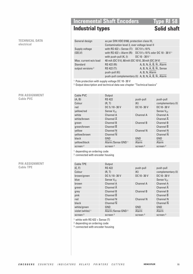
55E N C O D E R S C O U N T E R S I N D I C A T O R S R E L A Y S P R I N T E R S C U T T E R S
Incremental Shaft EncodersIndustrial types
Type RI 58Solid shaft
Cable PVC Output(A, B) RS 422 push-pull push-pullColour (R, T) (K) complementary (I)red DC 5 / 10 - 30 V DC 10 - 30 V DC 10 - 30 Vyellow/red Sense VCC Sense VCC
white Channel A Channel A Channel Awhite/brown Channel Channel green Channel B Channel B Channel Bgreen/brown Channel Channel yellow Channel N Channel N Channel Nyellow/brown Channel Channel black GND GND GNDyellow/black /Sense GND 1
screen 2 screen 2 screen 2 screen 2AlarmAlarmAlarm
NN
BB
AA
PIN ASSIGNMENTCable PVC
PIN ASSIGNMENTCable TPE
Cable TPE Output(E, F) RS 422 push-pull push-pullColour (R, T) (K) complementary (I)brown/green DC 5 / 10 - 30 V DC 10 - 30 V DC 10 - 30 Vblue Sense VCC Sense VCC
brown Channel A Channel A Channel Agreen Channel Channel grey Channel B Channel B Channel Bpink Channel Channel red Channel N Channel N Channel Nblack Channel Channel white/green GND GND GNDviolet (white) 1 /Sense GND 2
screen 3 screen 3 screen 3 screen 3AlarmAlarmAlarm
NN
BB
AA
TECHNICAL DATAelectrical
General design as per DIN VDE 0160, protection class III, Contamination level 2, over voltage level II
Supply voltage with RS 422 + Sense (T): DC 5 V ± 10 %(SELV) with RS 422 + Alarm (R): DC 5 V ± 10 % oder DC 10 - 30 V 1
with push-pull (K, I): DC 10 - 30 V 1
Max. current w/o load 40 mA (DC 5 V), 60 mA (DC 10 V), 30 mA (DC 24 V)Standard RS 422 (R): A, B, N, , , , output versions 2 RS 422 (T): A, B, N, , , , Sense
push-pull (K): A, B, N, push-pull complementary (I): A, B, N, , , , AlarmNBA
AlarmNBA
AlarmNBA
1 Pole protection with supply voltage DC 10 - 30 V2 Output description and technical data see chapter “Technical basics”
1 depending on ordering code2 connected with encoder housing
1 white with RS 422 + Sense (T)2 depending on ordering code3 connected with encoder housing

56 E N C O D E R S C O U N T E R S I N D I C A T O R S R E L A Y S P R I N T E R S C U T T E R S
Incremental Shaft EncodersIndustrial types
Type RI 58Solid shaft
Pin Description RS 422/Euro-pinout push-pull push-pull(Connection codes O and K) complementary
1/A Channel A Channel A Channel A2/B Channel B Channel B Channel B3/C Channel N Channel N Channel N4/D DC 5/10 - 30 V DC 10 - 30 V DC 10 - 30 V5/E6/F GND GND GND7/G Channel screen Channel 8/H Channel N.C. Channel 9/I Channel N.C. Channel
10/J screen screen screenNNBBAA
AlarmAlarmAlarm
CONNECTOR 10 POLE (MIL)
CONNECTOR 6 POLE(BINDER)
Description (push-pull) Pin (Stifte)DC 10 - 30 V 1Channel A 2Channel N 3Channel B 4
5GND 6Alarm
Pin RS 422 + RS 422 + push-pull push-pullSense (T) Alarm (R) (K) complementary (I)
1 Channel Channel N.C. Channel 2 Sense VCC Sense VCC N.C. Sense VCC
3 Channel N Channel N Channel N Channel N4 Channel Channel N.C. Channel 5 Channel A Channel A Channel A Channel A6 Channel Channel N.C. Channel 7 N.C.8 Channel B Channel B Channel B Channel B9 N.C. 1 N.C. 1 N.C. 1 N.C. 1
10 GND GND GND GND11 Sense GND N.C. N.C. N.C.12 DC 5 V DC 5/10 - 30 V DC 10 - 30 V DC 10 - 30 V
AlarmAlarmAlarmAAA
NNN
BBB
CONNECTOR 12 POLE (CONIN)
Pin assignmentconnector counterclockwise (CCW)
connectorclockwise (cw)
1 screen for cable with CONIN connector
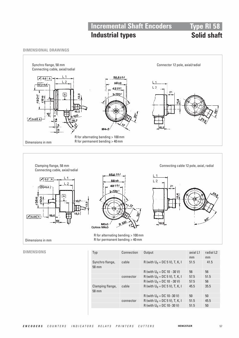
57E N C O D E R S C O U N T E R S I N D I C A T O R S R E L A Y S P R I N T E R S C U T T E R S
Incremental Shaft EncodersIndustrial types
Type RI 58Solid shaft
Dimensions in mm
Dimensions in mm
DIMENSIONAL DRAWINGS
Typ Connection Output axial L1 radial L2mm mm
Synchro flange, cable R (with UB = DC 5 V), T, K, I 51.5 41.558 mm
R (with UB = DC 10 - 30 V) 56 56connector R (with UB = DC 5 V), T, K, I 57.5 51.5
R (with UB = DC 10 - 30 V) 57.5 56Clamping flange, cable R (with UB = DC 5 V), T, K, I 45.5 35.558 mm
R (with UB = DC 10 - 30 V) 50 50connector R (with UB = DC 5 V), T, K, I 51.5 45.5
R (with UB = DC 10 - 30 V) 51.5 50
DIMENSIONS
Synchro flange, 58 mmConnecting cable, axial/radial
Connector 12 pole, axial/radial
Clamping flange, 58 mmConnecting cable, axial/radial
Connecting cable 12 pole, axial, radial
R for alternating bending > 100 mmR for permanent bending > 40 mm
R for alternating bending > 100 mmR for permanent bending > 40 mm

58 E N C O D E R S C O U N T E R S I N D I C A T O R S R E L A Y S P R I N T E R S C U T T E R S
Incremental Shaft EncodersIndustrial types
Type RI 58Solid shaft
Dimensions in mm
DIMENSIONAL DRAWINGS
Square flange, 80 x 80 mm
Square flange,63.5 x 63.5 mm (2.5” x 2.5”)
*Dimensions in mm; L1, L2 see clamping flange
Dimensions in mm
Synchro clamping flange,63.5 mm (2.5”)
R for alternating bending > 100 mmR for permanent bending > 40 mm
screw thread
MIL6 ... 10 pole

59E N C O D E R S C O U N T E R S I N D I C A T O R S R E L A Y S P R I N T E R S C U T T E R S
Incremental Shaft EncodersGuide for selection
Type RI 58Solid shaft
STANDARD VERSIONS
RI 58 - O
1 ... 10 000
4 = IP65/647 = IP67/67
3* = 7 mm6 = 9.52 mm2 = 10 mm7* = 12 mm
S = synchro flangeØ 58
4 = IP65/647 = IP67/67
1 = 6 mm5 = 6.35 mm
M = syn.clamping fl.Ø 63.5
4 = IP65/647 = IP67/67
6 = 9.52 mm
Q = square flange63.5 x 63.5
4 = IP65/647 = IP67/67
6 = 9.52 mm2 = 10 mm
G = square flange80 x 80
4 = IP65/64
3 = 7 mm
A = DC 5 V E = DC 10 - 30 V
T = RS 422 + Sense R = RS 422 + Alarm I = push-pullcomplementary R = RS 422 + Alarm K = push-pull
A = cable PVC, axialB = cable PVC, radialC = Conin, axial, cwD = Conin, radial, cwE = cable TPE, axialF = cable TPE, radialG = Conin, axial, ccwH = Conin, radial, ccw
A = cable PVC, axialB = cable PVC, radialC = Conin, axial, cwD = Conin, radial, cwE = cable TPE, axialF = cable TPE, radialG = Conin, axial, ccwH = Conin, radial, ccwK* = MIL 10 pole, radialO* = MIL 10 pole, axial
A = cable PVC, axialB = cable PVC, radialC = Conin, axial, cwD = Conin, radial, cwE = cable TPE, axialF = cable TPE, radialG = Conin, axial, ccwH = Conin, radial, ccwK* = MIL 10 pole, radialO* = MIL 10 pole, axial
A = cable PVC, axialB = cable PVC, radialC = Conin, axial, cwD = Conin, radial, cwE = cable TPE, axialF = cable TPE, radialG = Conin, axial, ccwH = Conin, radial, ccwJ = Binder 6 pole, radialN = Binder 6 pole, axialK* = MIL 10 pole, radialO* = MIL 10 pole, axial
K = clamping flangeØ 58
Version
Number of pulses
Type offlange **
Protection class housing/bearings
Shaft
Supplyvoltage
Output
Connection
* not for IP67** other flange versions can be realized by combination of clamping flange + flange adapter (see Accessories)
e.g. RI58 with synchro flange and 10 mm-shaft: version clamping flange with 10 mm-shaft + synchro flange adapter (1 522 328)

60 E N C O D E R S C O U N T E R S I N D I C A T O R S R E L A Y S P R I N T E R S C U T T E R S
Incremental Shaft EncodersGuide for selection
Type RI 58Solid shaft
RI 58 - T
4 ... 2500
4 = IP65/647 = IP67/67
3* = 7 mm6 = 9.52 mm2 = 10 mm7* = 12 mm
S = Synchro flangeØ 58
4 = IP65/647 = IP67/67
1 = 6 mm5 = 6.35 mm
M = Syn.clamping fl.Ø 63.5
4 = IP65/647 = IP67/67
6 = 9.52 mm
Q = square flange63.5 x 63.5
4 = IP65/647 = IP67/67
6 = 9.52 mm2 = 10 mm
G = square flange80 x 80
4 = IP65/64
3 = 7 mm
A = DC 5 V E = DC 10 - 30 V
T = RS 422 + Alarm R = RS 422 +Sense K = push-pull
C = Conin, axial, cwD = Conin, radial, cwE = cable TPE, axialF = cable TPE, radialG = Conin, axial, ccwH = Conin, radial, ccwK* = MIL 10 pole, radialO* = MIL 10 pole, axial
C = Conin, axial, cwD = Conin, radial, cwE = cable TPE, axialF = cable TPE, radialG = Conin, axial, ccwH = Conin, radial, ccw
C = Conin, axial, cwD = Conin, radial, cwE = cable TPE, axialF = cable TPE, radialG = Conin, axial, ccwG = Conin, radial, ccwJ = Binder 6 pole, radialN= Binder 6 pole, axialK* = MIL 10 pole, radialO* = MIL 10 pole, axial
K = clamping flangeØ 58
Version
Number of pulses
Type offlange **
Protection class housing/bearings
Shaft
Supplyvoltage
Output
Connection
STANDARD VERSIONS100 °C max. operation temperature
* not for IP67** other flange versions can be realized by combination of clamping flange + flange adapter (see Accessories)
e.g. RI58 with synchro flange and 10 mm-shaft: version clamping flange with 10 mm-shaft + synchro flange adapter (1 522 328)
Further versions on request
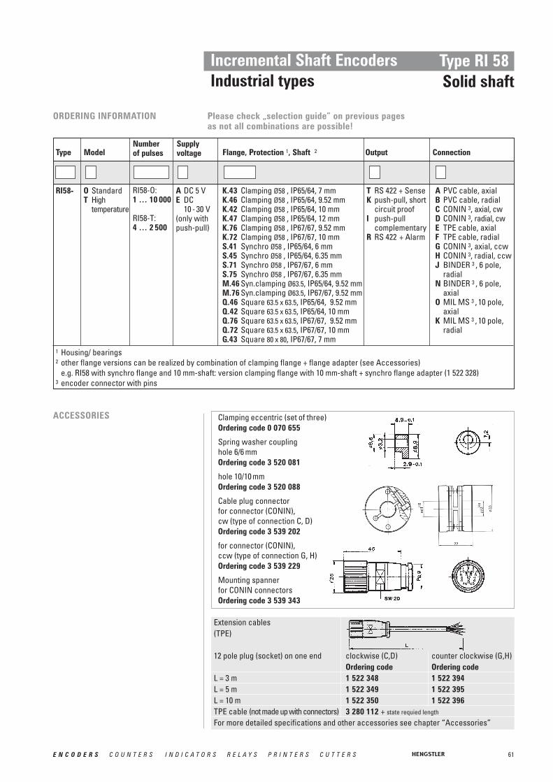
Extension cables(TPE)
12 pole plug (socket) on one end clockwise (C,D) counter clockwise (G,H)Ordering code Ordering code
L = 3 m 1 522 348 1 522 394L = 5 m 1 522 349 1 522 395L = 10 m 1 522 350 1 522 396TPE cable (not made up with connectors) 3 280 112 + state requied length
For more detailed specifications and other accessories see chapter “Accessories”
Please check „selection guide” on previous pages as not all combinations are possible!
61E N C O D E R S C O U N T E R S I N D I C A T O R S R E L A Y S P R I N T E R S C U T T E R S
Incremental Shaft EncodersIndustrial types
Type RI 58Solid shaft
Clamping eccentric (set of three)Ordering code 0 070 655
Spring washer couplinghole 6/6 mmOrdering code 3 520 081
hole 10/10 mmOrdering code 3 520 088
Cable plug connectorfor connector (CONIN), cw (type of connection C, D)Ordering code 3 539 202
for connector (CONIN),ccw (type of connection G, H)Ordering code 3 539 229
Mounting spanner for CONIN connectorsOrdering code 3 539 343
ACCESSORIES
1 Housing/ bearings2 other flange versions can be realized by combination of clamping flange + flange adapter (see Accessories)
e.g. RI58 with synchro flange and 10 mm-shaft: version clamping flange with 10 mm-shaft + synchro flange adapter (1 522 328)3 encoder connector with pins
ORDERING INFORMATION
Supplyvoltage Flange, Protection 1, Shaft 2
Numberof pulsesType Model
A DC 5 VE DC
10 - 30 V (only with push-pull)
K.43 Clamping Ø58 , IP65/64, 7 mm K.46 Clamping Ø58 , IP65/64, 9.52 mmK.42 Clamping Ø58 , IP65/64, 10 mmK.47 Clamping Ø58 , IP65/64, 12 mmK.76 Clamping Ø58 , IP67/67, 9.52 mmK.72 Clamping Ø58 , IP67/67, 10 mmS.41 Synchro Ø58 , IP65/64, 6 mmS.45 Synchro Ø58 , IP65/64, 6.35 mmS.71 Synchro Ø58 , IP67/67, 6 mmS.75 Synchro Ø58 , IP67/67, 6.35 mmM.46 Syn.clamping Ø63.5, IP65/64, 9.52 mmM.76 Syn.clamping Ø63.5, IP67/67, 9.52 mmQ.46 Square 63.5 x 63.5, IP65/64, 9.52 mmQ.42 Square 63.5 x 63.5, IP65/64, 10 mmQ.76 Square 63.5 x 63.5, IP67/67, 9.52 mmQ.72 Square 63.5 x 63.5, IP67/67, 10 mmG.43 Square 80 x 80, IP67/67, 7 mm
RI58-O: 1 … 10 000
RI58-T:4 … 2 500
RI58- O StandardT High
temperature
Output Connection
T RS 422 + SenseK push-pull, short
circuit proofI push-pull
complementaryR RS 422 + Alarm
A PVC cable, axialB PVC cable, radialC CONIN 3, axial, cw D CONIN 3, radial, cwE TPE cable, axialF TPE cable, radialG CONIN 3, axial, ccw H CONIN 3, radial, ccw J BINDER 3 , 6 pole,
radialN BINDER 3 , 6 pole,
axialO MIL MS 3 , 10 pole,
axialK MIL MS 3 , 10 pole,
radial

62 E N C O D E R S C O U N T E R S I N D I C A T O R S R E L A Y S P R I N T E R S C U T T E R S
Incremental Shaft EncodersIndustrial types
Type RI 36-HHollow shaft
TECHNICAL DATAelectrical
NUMBER OF PULSES
TECHNICAL DATAmechanical
5 / 10 / 20 / 25 / 50 / 60 / 100 / 200 / 250 / 300 / 360 / 500 / 600 / 720 / 1000 / 1024 / 1250 / 1500 / 2000 / 2048 / 2500 / 3000 / 3600Other number of pulses on request
Mounting Clamping shaft (one side open) with clamping ring frontCoupling Hubshaft with tetherShaft diameter 4, 6, 8, 10 mm hollow shaftAngular shaftmisalignment max. ±0.15 mm radial, ±0.5 mm axialAbsolute max. speed max. 10 000 min-1
Torque ≤ 1 NcmMoment of inertia approx. 3 gcm2
Protection class (EN 60529) Housing IP64, bearings IP64Operating temperature –10 … +70 °CStorage temperature –25 … +85 °CVibration resistance 100 m/s2 (10 … 2000 Hz)Shock resistance 1000 m/s2 (6 ms)Connection 1.5 m cable 1 axial or radialHousing AluminiumWeight approx. 80 g
1 Other cable length on request
■ miniature industry encoder for high number of pulses■ short mounting length■ easy mounting procedure■ Application e.g.:
- Motors- Machine tools- Packaging Machines- Robots- Automated SMD equipment
General design as per DIN VDE 0160, protection class III, contamination level 2, overvoltage class II
Supply voltage with RS 422 (R, T): DC 5 V ± 10 %(SELV) with push-pull (K, I): DC 10 - 30 V 2
Max. current w/o load 40 mA (DC 5 V), 60 mA (DC 10 V), 30 mA (DC 24 V)Standard RS 422 (R): A, B, N, , , , output versions 3 RS 422 (T): A, B, N, , , , Sense
push-pull (K): A, B, N, push-pull complementary (I): A, B, N, , , , AlarmNBA
AlarmNBA
AlarmNBA
2 Pole protection3 Output description and technical data see chapter “Technical basics”

63E N C O D E R S C O U N T E R S I N D I C A T O R S R E L A Y S P R I N T E R S C U T T E R S
Incremental Shaft EncodersIndustrial types
Type RI 36-HHollow shaft
DIMENSIONAL DRAWINGS
Dimensions in mm
The hubshaft with tether (F) as torque support must be fixes by a cylindric pin (2.4 mm ∅)
at the machine side
Dim.: Hollow shaft ∅ Unit
A 4 +0.01 6 +0.01 8 +0.01 10 +0.01 mm
A* 4 g7 10 g7 8 g7 10 g7 mm
B 4.8±0.2 4.8±0.2 5.3±0.2 5.3±0.2 mm
D 12 14 16 18 mm
L min 6 9 12 15 mm
L max 20 20 20 20 mm
A* = diameter of connection shaftB = space between housing and shaftD = ∅ clamping ringL = length of connection shaft
R for alternating bending ≥ 100 mmR for permanent bending ≤ 40 mm
Tightening torque of set screw 15 Ncm
Torque support “F”
Torque support “J”
cable radial

64 E N C O D E R S C O U N T E R S I N D I C A T O R S R E L A Y S P R I N T E R S C U T T E R S
Incremental Shaft EncodersIndustrial types
Type RI 36-HHollow shaft
Cable PVC Output(A, B) RS 422 push-pull push-pullColour Litze mm2 (R, T) (K) complementary (I)red 0.5 DC 5 V DC 10 - 30 V DC 10 - 30 Vyellow/red 0.14 Sense VCC Sense VCC
white 0.14 Channel A Channel A Channel Awhite/brown 0.14 Channel Channel green 0.14 Channel B Channel B Channel Bgreen/brown 0.14 Channel Channel yellow 0.14 Channel N Channel N Channel Nyellow/brown 0.14 Channel Channel black 0.5 GND GND GNDyellow/black 0.14 /Sense GND 1
screen 2 screen 2 screen 2 screen 2
AlarmAlarmAlarm
NN
BB
AA
PIN ASSIGNMENT
1 depending on ordering code2 connected with encoder housing
ORDERING INFORMATION
Supplyvoltage Flange, Protection, Shaft
Number of pulsesType Model
A DC 5 VE DC 10 - 30 V
(only with push-pull)
F.30 Clamping, IP64, 4 mm *F.31 Clamping, IP64, 6 mm *F.3C Clamping, IP64, 8 mm *F.32 Clamping, IP64, 10 mm *J.30 Clamping, IP64, 4 mm **
J.31 Clamping, IP64, 6 mm **
J.3C Clamping, IP64, 8 mm **
J.32 Clamping, IP64, 10 mm **
5 … 3 600 RI36- H Hollow shaft
Output Connection
T RS 422 + SenseK push-pull
short circuit proofR RS 422 + AlarmI push-pull
complementary
A Cable axialB Cable radial
* Fixing of hubshaft with tether by cylindrical pin** Fixing of hubshaft with tether by oblong hole

65E N C O D E R S C O U N T E R S I N D I C A T O R S R E L A Y S P R I N T E R S C U T T E R S
Incremental Shaft EncodersIndustrial types
Type RI 58-HHollow shaft
1 / 2 / 3 / 4 / 5 / 10 / 15 / 20 / 25 / 30 / 35 / 40 / 45 / 50 / 60 / 64 / 70 / 72 / 80 / 100 / 125 / 128 / 144/ 150 / 180 / 200 / 250 / 256 / 300 / 314 / 350 / 360 / 375 / 400 / 460 / 480 / 500 / 512 / 600 / 625 / 720 / 900 / 1000 / 1024 / 1250 / 1500 / 1600 / 1800 / 2000 / 2048 / 2500 /3000 / 3480 / 3600 / 4000 / 4096 / 5000Other number of pulses on requestPreferably available versions are printed in bold type.
Shaft diameter 10 mm hollow shaft12 mm hollow shaft
Required dimension of mounting shaft Ø 10 mm, tolerance g8 (-0.005 … -0.027 mm)Ø 12 mm, tolerance g8 (-0.006 … -0.033 mm)
Balance tolerancesMisalignment axial ± 0.4 mmMisalignment parallel 0.4 mmMisalignment angular 1°Absolute max. speed max. 3000 min-1
Torque ≤ Ncm (IP64)Moment of inertia approx. 65 gcm2 (10 mm shaft)
approx. 95 gcm2 (12 mm shaft)Protection class (EN 60529) Housing IP64, bearings IP64Operating temperature an Welle –10 … +70 °CStorage temperature –25 … +85 °CVibration resistance (IEC 68-2-6) 10 g = 100 m/s2 (10 … 2 kHz)Shock resistance (IEC 68-2-27) 100 g = 1 000 m/s2 (6 ms)Connection Cable radial, 1.5 m 1
Housing AluminiumFlange Synchro flangeWeight approx. 210 g
NUMBER OF PULSES
TECHNICAL DATAmechanical
■ Through shaft■ High accuracy by means of integrated flexible coupling■ Safe shaft mounting■ Application e.g.:
- textile machines- motors- drives- copiers
1 Other cable length on request

66 E N C O D E R S C O U N T E R S I N D I C A T O R S R E L A Y S P R I N T E R S C U T T E R S
Incremental Shaft EncodersIndustrial types
Type RI 58-HHollow shaft
TECHNICAL DATAelectrical
General design as per DIN VDE 0160, protection class III, contamination level 2, overvoltage class II
Supply voltage with RS 422 + Sense (T): DC 5 V ± 10 %with RS 422 + Alarm (R): DC 5 V ± 10 % oder DC 10 - 30 V 1
with push-pull (K, I): DC 10 - 30 V 1
Max. current w/o load 40 mA (DC 5 V), 60 mA (DC 10 V), 30 mA (DC 24 V)Standard RS 422 (R): A, B, N, , , , output versions 2 RS 422 (T): A, B, N, , , , Sense
push-pull (K): A, B, N, push-pull complementary (I): A, B, N, , , , AlarmNBA
AlarmNBA
AlarmNBA
∅ Hollow shaft Required dimensionof mounting shaft (g8)
10 mm – 0.005 … – 0.027 mm12 mm – 0.006 … – 0.033 mm
Dim.: ØA 10 mm* 12 mm*B 28 mm 33 mm
* ToleranceH7 = 0 … + 0.018 mm
DIMENSIONAL DRAWINGS
1 Pole protection with supply voltage DC 10 - 30 V2 Output description and technical data see chapter “Technical basics”
Synchro flange
R for alternating bending > 100 mmR for permanent bending > 40 mm
mounting thread M 4x5
Dimensions in mm

67E N C O D E R S C O U N T E R S I N D I C A T O R S R E L A Y S P R I N T E R S C U T T E R S
Incremental Shaft EncodersIndustrial types
Type RI 58-HHollow shaft
Connecting cable OutputColour Lead ∅ RS 422 push-pull
T and R K and Ired 0.5 mm2 DC 5/10 - 30 V DC 10 - 30 Vred/yellow 0.14 mm2 Sense VCC Sense VCCwhite 0.14 mm2 Channel A Channel Awhite/brown 0.14 mm2 Channel Channel 1
green 0.14 mm2 Channel B Channel Bgreen/brown 0.14 mm2 Channel Channel 1
yellow 0.14 mm2 Channel N Channel Nyellow/brown 0.14 mm2 Channel Channel 1
black 0.5 mm2 GND GND black/yellow 0.14 mm2 /Sense GND 2
screen 3 screen 3 screen 3AlarmAlarm
NN
BB
AA
Clamping eccentric (set of tree)Ordering code 0 070 655
PIN ASSIGNMENT
ACCESSORIES
1 only push-pull complementary (I)2 depending on ordering code3 connected with encoder housing
1 with output T, R2 with output K, I, R
ORDERING INFORMATION
Supplyvoltage Flange, Protection, Shaft
Number of pulsesType Model
A DC 5 V 1E DC 10 - 30 V 2
(only withpush-pull)
S.42 Synchro, IP64, 10 mmS.47 Synchro, IP64, 12 mm
1 … 5 000RI58- H Hollow shaft
Output Connection
K push-pullT RS 422+ SenseR RS 422+ AlarmI push-pull
complementary
B PVC cable radial
Dimensions in mm

68 E N C O D E R S C O U N T E R S I N D I C A T O R S R E L A Y S P R I N T E R S C U T T E R S
Incremental Shaft EncodersIndustrial types
Type RI 58-DHollow shaft
Blind shaft
Clamping shaft
NUMBER OF PULSES
TECHNICAL DATAmechanical
1 / 2 / 3 / 4 / 5 / 10 / 20 / 25 / 30 / 35 / 40 / 45 / 50 / 60 / 64 / 70 / 72 / 80 / 100 / 125 / 128 / 144 / 150 / 180 / 200 / 250 / 256 / 300 / 314 / 350 / 360 / 375 / 400 / 460 / 480 / 500 / 512 / 600 / 625 / 720 / 900 / 1000 / 1024 / 1250 / 1500 / 1600 / 1800 / 2000 / 2048 / 2500 /3000 / 3480 / 3600 / 4000 / 4096 / 5000
(high temperature) as above, but only for the range from 4 … 2500 pulsesOther number of pulses on requestPreferably available versions are printed in bold type.
■ Flexible hollow shaft design up to diameter 14 mm■ Short overall length■ Easy installation by means of clamping shaft or blind shaft■ Application e.g.:
- actuators- length measuring machines- motors
■ Operating temperature up to 100 °C (RI 58 TD)■ Various shaft versions:
Mounting code E = Blind shaft (not through)Mounting code F = Clamping shaft (not through)Mounting code D = Clamping shaft (solid shaft)
RI 58-D
RI 58 TD
Mounting Synchro flange with clamping shaft or blind shaftShaft diameter Hollow shaft 10 mm, hollow shaft 12 mm,
hollow shaft 14 mm (not through)Required dimensions of Ø 10 mm, tolerance g8 (-0.005…-0.027 mm)mounting shaft Ø 12/14 mm, tolerance g8 (-0.006…-0.033 mm)Absolute max. speed E, F: max. 6 000 min-1; D: max 4 000 min-1
Torque ≤ 1 Ncm with non-through shaft (E, F)≤ 2 Ncm with through shaft (D)
Moment of inertia F: approx. 35 gcm2 (clamping non through shaft)E: approx. 20 gcm2 (end shaft)D: approx. 60 gcm2 (clamping through shaft)
Protection class (EN 60529) E, F: housing IP65, bearings IP64D: housing IP64, bearings IP64
Operating temperature –10 … +70 °C, Option: -25 ...+100°CStorage temperature –25 … +85 °CVibration resistance (IEC 68-2-6) 10 g = 100 m/s2 (10 … 2 000 Hz)Shock resistance (IEC 68-2-27) 100 g = 1 000 m/s2 (6 ms)Connection 1.5 m cable 1 or connector, radialHousing AluminiumWeight approx. E, F: 170 g; D: 190 g
1 Other cable length on request
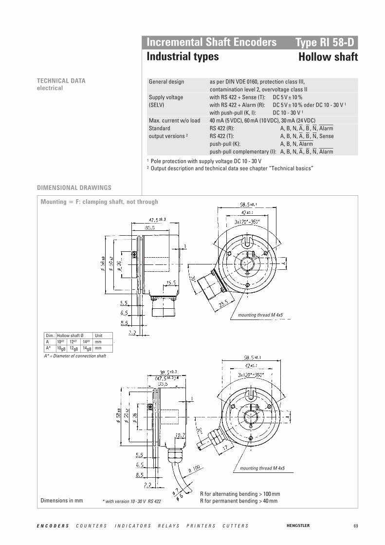
69E N C O D E R S C O U N T E R S I N D I C A T O R S R E L A Y S P R I N T E R S C U T T E R S
Incremental Shaft EncodersIndustrial types
Type RI 58-DHollow shaft
TECHNICAL DATAelectrical
Mounting = F: clamping shaft, not through
General design as per DIN VDE 0160, protection class III, contamination level 2, overvoltage class II
Supply voltage with RS 422 + Sense (T): DC 5 V ± 10 %(SELV) with RS 422 + Alarm (R): DC 5 V ± 10 % oder DC 10 - 30 V 1
with push-pull (K, I): DC 10 - 30 V 1
Max. current w/o load 40 mA (5 VDC), 60 mA (10 VDC), 30 mA (24 VDC)Standard RS 422 (R): A, B, N, , , , output versions 2 RS 422 (T): A, B, N, , , , Sense
push-pull (K): A, B, N, push-pull complementary (I): A, B, N, , , , AlarmNBA
AlarmNBA
AlarmNBA
Dim.: Hollow shaft Ø UnitA 10H7 12H7 14H7 mmA* 10g8 12g8 14g8 mm
1 Pole protection with supply voltage DC 10 - 30 V2 Output description and technical data see chapter “Technical basics”
DIMENSIONAL DRAWINGS
R for alternating bending > 100 mmR for permanent bending > 40 mm
mounting thread M 4x5
* with version 10 - 30 V RS 422
mounting thread M 4x5
A* = Diameter of connection shaft
Dimensions in mm

70 E N C O D E R S C O U N T E R S I N D I C A T O R S R E L A Y S P R I N T E R S C U T T E R S
Incremental Shaft EncodersIndustrial types
Type RI 58-DHollow shaft
DIMENSIONAL DRAWINGS
Mounting = D: through shaft with clamping ring
H optionaL:Clamping ring at rear on request
mounting thread M 4x5
mounting thread M 4x5
R for alternating bending > 100 mmR for permanent bending > 40 mm
R for alternating bending > 100 mmR for permanent bending > 40 mm
Dim. Hollow shaft Ø UnitA 10H7 12H7 14H7 mmA* 10g8 12g8 14g8 mm
view turned 60°
view turned 60°
* with Version 10 - 30 V RS 422
A* = Diameter of connection shaft14 mm on request
Dimensions in mm
Dimensions in mm

71E N C O D E R S C O U N T E R S I N D I C A T O R S R E L A Y S P R I N T E R S C U T T E R S
Incremental Shaft EncodersIndustrial types
Type RI 58-DHollow shaft
Mounting = E, blind shaft (not through)
DIMENSIONAL DRAWINGS
* with Version 10 - 30 V RS 422
mounting thread M 4x5
mounting thread M 4x5
Dim. Hollow shaft Ø UnitA 10H7 12H7 14H7 mmA* 10g8 12g8 14g8 mm
A* = Diameter of connection shaft
R for alternating bending > 100 mmR for permanent bending > 40 mm
Dimensions in mm

72 E N C O D E R S C O U N T E R S I N D I C A T O R S R E L A Y S P R I N T E R S C U T T E R S
Incremental Shaft EncodersIndustrial types
Type RI 58-DHollow shaft
Cable Output circuitPVC RS 422 RS 422 push-pull (K) push-pullColour + Sense (T) + Alarm (R) complementary (I)white Channel A Channel A Channel A Channel Awhite/brown Channel Channel Channel green Channel B Channel B Channel B Channel Bgreen/brown Channel Channel Channel yellow Channel N Channel N Channel N Channel Nyellow/brown Channel Channel Channel yellow/black Sense GNDyellow/red Sense VCC Sense VCC Sense VCC
red DC 5 V DC 5 / 10 - 30 V DC 10 - 30 V DC 10 - 30 Vblack GND GND GND GNDCable screen 1 Cable screen 1 Cable screen 1 Cable screen 1 Cable screen 1
AlarmAlarmAlarmNNN
BBB
AAA
PIN ASSIGNMENTCable PVC
Cable Output circuitTPE RS 422 RS 422 push-pull (K) push-pullColour + Sense (T) + Alarm (R) complementary (I)brown Channel A Channel A Channel A Channel Agreen Channel Channel Channel grey Channel B Channel B Channel B Channel Bpink Channel Channel Channel red Channel N Channel N Channel N Channel Nblack Channel Channel Channel violet (white) 2 Sense GNDblue Sense VCC Sense VCC Sense VCC
brown/green DC 5 V DC 5 / 10 - 30 V DC 10 - 30 V DC 10 - 30 Vwhite/green GND GND GND GNDCable screen 1 Cable screen 1 Cable screen 1 Cable screen 1 Cable screen 1
AlarmAlarmAlarmNNN
BBB
AAA
PIN ASSIGNMENTCable TPE
Preparation of the drive shaft(only in mounting = E):The drive shaft must be provided with athreaded bore M 4 x10:This bore accepts the fastening screw of the shaft encoder.
Dimensions in mm also apply for shaft-∅ 10 or 14 Dimensions in mm also apply for shaft-∅ 10 or 14
Mounting = D, F (Clamping shaft) Mounting = E (Blind shaft)
Preparation of the machine flange 1
(all mounting versions):In the machine flange a straight pin must beinstalled (diameter 4x16 resp. 4x20, DIN 6325).This pin is required as a torque support.
MOUNTING NECESSITIES In order to be able to compensate an axial and radial misalignment of the shaft, theencoder flange must not be fixed rigidly. Fix the flanges by means of a stator coupling (e.g.hubshaft with tether) as torque support (see “Accessories”) or by means of a cylindrical pin:
1 Or as an option: stator coupling as torque support
1 connected with encoder housing

73E N C O D E R S C O U N T E R S I N D I C A T O R S R E L A Y S P R I N T E R S C U T T E R S
Incremental Shaft EncodersIndustrial types
Type RI 58-DHollow shaft
Pin RS 422 RS 422 push-pull (K) push-pull + Sense (T) + Alarm (R) complementary (I)
1 Channel Channel N.C. Channel 2 Sense VCC Sense VCC N.C. Sense VCC
3 Channel N Channel N Channel N Channel N4 Channel Channel N.C. Channel 5 Channel A Channel A Channel A Channel A6 Channel Channel N.C. Channel 7 N.C.8 Channel B Channel B Channel B Channel B9 N.C. 1 N.C. 1 N.C. 1 N.C. 1
10 GND GND GND GND11 Sense GND N.C. N.C. N.C.
12 DC 5 V DC 5 / 10 - 30 V DC 10 - 30 V DC 10 - 30 V
AlarmAlarmAlarmAAA
NNN
BBB
PIN ASSIGNMENTConnector (CONIN)
ACCESSORIES Hubshaft with tether as stator coupling: ordering code 1 531 162
1 screen for cable with CONIN connector
1 Mounting E, F: no through shaft (blind hole )2 through shaft, only connection cable3 only with mounting E or F (no through shaft)4 with output T, R5 with output K, I, R
ORDERING INFORMATION
Supplyvoltage Flange, Protection, Shaft
Number of pulsesType Model
A DC 5 V 4E DC10 - 30 V 5
(only with push-pull)
E.42 Blind shaft 1 , IP64/64, 10 mmE.47 Blind shaft 1 , IP64/64, 12 mmE.49 Blind shaft 1 , IP64/64, 14 mmF.42 Blind shaft 1 , IP64/64, 10 mmF.47 Blind shaft 1 , IP64/64, 12 mmF.49 Blind shaft 1 , IP64/64, 14 mmD.32 Clamping shaft front 2,
IP64/64, 10 mmD.37 Clamping shaft front 2,
IP64/64, 12 mm
1 … 5 000 RI58- D Hollow shaft
TD Hollow shaft100 °C
Output Connection
K push-pullT RS 422 + SenseR RS 422 + AlarmI push-pull
complementary
B PVC cable radialF TPE cable radialD CONIN radial, cw 3H CONIN radial,
ccw 3
Dimensions in mm

74 E N C O D E R S C O U N T E R S I N D I C A T O R S R E L A Y S P R I N T E R S C U T T E R S
Incremental Shaft EncodersIndustrial types
Type RI 76 TDHollow shaft
■ Through shaft with up to diameter 42 mm■ Short overall length with an outside diameter of only 76 mm■ Easy installation by means of clamping ring■ Operating temperature up to 100 °C■ Application e.g.:
- motors- printing machines- lifts
TECHNICAL DATAmechanical
Shaft fixation Clamping ring, front or rearCoupling stator coupling (hubshaft with tether)Shaft diameter 15…42 mm (Available: 15, 16, 18, 20, 24, 25, 27,
28, 30, 32, 38, 40, 42 mm as well as 5 ⁄ 8“, 1 5 ⁄ 8“, 3 ⁄ 4“Mimimum length of mounting shaftFront clamping ring 32 mm with Ø 15 ... 30, 35 mm with Ø >30 ... 42 Rear clamping ring corresponding to total length of encoder
Max. parallel shaft misalignmentwith stator coupling A (flexible) ±2.0 mm axial, ±0.15 mm radialwith 1x stator coupling N (torsionally rigid) ±0.5 mm axial, ±0.3 mm radialwith 2x stator coupling N (torsionally rigid) ±0.3 mm axial, ±0.2 mm radial
Absolute max. speed at 70 °C and IP64: 3 600 min-1 für Ø 15 ... 25at 70 °C and IP64: 1 800 min-1 für Ø >25 ... 42at 70 °C and IP40: 6 000 min-1 für Ø 15 ... 42at 100 °C always: 1 800 min-1 für Ø 15 ... 42
Torque 3…10 Ncm (depending on version )Moment of inertia 140...420 gcm2 (depending on version)Protection class (EN 60529) Housing IP50, bearings IP40
Option: Housing IP65, bearings IP64Operating temperature -25 ... +100 °CStorage temperature -25 ... +100 °CVibration resistance (IEC 68-2-6) 10 g = 100 m/s2 (10 ... 2000 Hz)Shock resistance (IEC 68-2-27) 100 g = 1000 m/s2 (6 ms)Connection 1.5 m cablel 1 radialHousing AluminiumWeight 320 - 580 g (depending on version)
NUMBER OF PULSES 50 / 100 / 128 / 250 / 256 / 300 / 314 / 360 / 500 / 600 / 720 / 900 / 1000 / 1024 / 1250 / 1500 / 2048 /2500 / 3072 / 4096 / 5000 / 8192 / 9000 / 10000Other number of pulses on request
1 Other cable length on request

75E N C O D E R S C O U N T E R S I N D I C A T O R S R E L A Y S P R I N T E R S C U T T E R S
Incremental Shaft EncodersIndustrial types
Type RI 76 TDHollow shaft
TECHNICAL DATAelectrical
General design as per DIN EN 61010-Part 1, protection class III, Contamination level 2, over voltage level II
Supply voltage with RS 422 +Sense (T): DC 5 V ± 10 %(SELV) with RS 422 +Alarm (R): DC 5 V ±10 % oder DC 10 - 30 V 1
with push-pull (K, I): DC 10 - 30 V 1
Max. current w/o load max. 60 mA (DC 5 V), 60 mA (DC 10 V), 35 mA (DC 24 V)Standard RS 422 (R): A, B, N, , , , output versions 2 RS 422 (T): A, B, N, , , , Sense
push-pull (K): A, B, N, push-pull complementary (I): A, B, N, , , , AlarmNBA
AlarmNBA
AlarmNBA
1 Pole protection with supply voltage DC 10 - 30 V2 Output description and technical data see chapter “Technical basics”
WITH HUBSHAFT WITH TETHER”RIGID”
WITH HUBSHAFT WITH TETHER”FLEXIBLE”
DIMENSIONAL DRAWINGS
R for alternating bending > 100 mmR for permanent bending > 40 mm
R for alternating bending > 100 mmR for permanent bending > 40 mm
* Values in brackets for shaft diameter >30Diameter of connection shaft 15g8 … 42g8
* Values in brackets for shaft diameter >30Diameter of connection shaft 15g8 … 42g8
Dimensions in mm
Dimensions in mm

76 E N C O D E R S C O U N T E R S I N D I C A T O R S R E L A Y S P R I N T E R S C U T T E R S
Incremental Shaft EncodersIndustrial types
Type RI 76 TDHollow shaft
Output circuitColour (TPE) RS 422 RS 422 push-pull (K) push-pull
+ Sense (T) + Alarm (R) complementary (I)brown Channel A Channel A Channel A Channel Agreen Channel Channel Channel grey Channel B Channel B Channel B Channel Bpink Channel Channel Channel red Channel N Channel N Channel N Channel Nblack Channel Channel Channel violet (white) 2 Sense GND blue Sense VCC Sense VCC Sense VCC
brown/green DC 5 V DC 5/10 .- 30 V DC 10 - 30 V DC 10 - 30 Vwhite/green GND GND GND GNDCable screen 1 Cable screen 1 Cable screen 1 Cable screen 1 Cable screen 1
AlarmAlarmAlarmNNN
BBB
AAA
PIN ASSIGNMENT Cable TPE
Hubshaft with tether flexible ordering code 1 533 079Hubshaft with tether rigid ordering code 1 533 078
ACCESSORIES
1 connected with encoder housing2 white for version Sense (T)
SHAFT CONNECTION Shaft fixing is done through a clamping ring either on the flange or cap side. As a rule,flange side clamping is better for smaller motors as the available shaft stub is corre-spondingly shorter.
On the other hand, cap side clamping is easier when there is sufficient shaft length available.
MOUNTING NECESSITIESIn order to compensate for axial and radial shaft eccentricity as well as any angle offset, theencoder flange must not be rigidly mounted. Please mount the flange with a flexible statorcoupling (e.g. hubshaft with tether) as torque support.
There are two flexible mounting plates:• A flexible hubshaft with tether (A) for higher levels of play and lower requirements
for accuracy.• A rigid hubshaft with tether (N) for reduced play and rigid connection with reduced
swing angle. This is suitable in the case of higher accuracy and dynamics requirements.
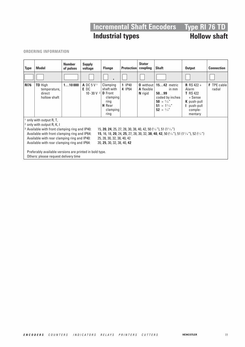
77E N C O D E R S C O U N T E R S I N D I C A T O R S R E L A Y S P R I N T E R S C U T T E R S
Incremental Shaft EncodersIndustrial types
Type RI 76 TDHollow shaft
1 only with output R, T, 2 only with output R, K, I3 Available with front clamping ring and IP40: 15, 20, 24, 25, 27, 28, 30, 38, 40, 42, 50 (5 ⁄ 8 “), 51 (1 5 ⁄ 8 “)
Available with front clamping ring and IP64: 15, 16, 18, 20, 24, 25, 27, 28, 30, 32, 38, 40, 42, 50 (5 ⁄ 8 “), 51 (1 5 ⁄ 8 “), 52 (3 ⁄ 4 “)Available with rear clamping ring and IP40: 25, 28, 30, 32, 38, 40, 42Available with rear clamping ring and IP64: 20, 25, 30, 32, 38, 40, 42
Preferably available versions are printed in bold type.Others: please request delivery time
ORDERING INFORMATION
Supplyvoltage Flange Protection
Statorcoupling Shaft
Number of pulsesType Model
A DC 5 V 1E DC
10 - 30 V 2
Clampingshaft withD Front
clampingring
H Rearclampingring
1 IP404 IP64
O withoutA flexibleN rigid
15…42 metricin mm
50…99coded by inches50 = 5 ⁄ 8“51 = 1 5 ⁄ 8“52 = 3 ⁄ 4“
1…10 000 RI76 TD High temperature, direct hollow shaft
.Output Connection
R RS 422 +AlarmT RS 422
+ SenseK push-pullI push-pull
comple-mentary
F TPE cable radial

78 E N C O D E R S C O U N T E R S I N D I C A T O R S R E L A Y S P R I N T E R S C U T T E R S
TECHNICAL DATAelectrical
General design As per DIN EN 61010, protection class III, Contamination level 2 , over voltage class II
Supply voltage DC 5V±10% or DC 5 - 30V 1
Max. current w/o load max 60mA (DC 5V), 60mA (DC 10V), 35mA (DC 24V)Standard With RS 422 (R): A, B, N, , , , , Senseoutput versions With push-pull (K): A, B, N,
With push-pull (I): A, B, N, , , , , SenseConnection Sub-D 15-pole, cable radial
AlarmNBAAlarm
AlarmNBA
1 Pole protection with supply voltage DC 5…30 V
Incremental Shaft EncodersIndustrial types
Type RI 80-EHollow shaft
■ Incremental Output■ 30...45 mm hollow shaft ■ Rugged mechanical design■ Unbreakable disc■ Integrated diagnostic system■ Wide voltage range DC 5 … 30 V
TECHNICAL DATAmechanical
Shaft fixation Keyway, set screw Coupling Spring tether (single, double)Protection IP50, IP64Max. Speed 3 600 min-1 (IP50)
1 500 min-1 (IP64) Moment of inertia 240 kgmm2
Max. parallel shaft axial: ± 0.5 mmmisalignment radial: ± 0.05 mmOperating temperature -20 ...+70°C Storage temperature -40 ...+70°C Material housing Glass fiber-reinforced plastic/ aluminum Weight 1000 g
NUMBER OF PULSES
GENERAL INFORMATION
1024 / 2048 / 4096Other number of pulses on request
The central element of the RI80-E is the latest Hengstler OptoAsic technology, which offersthe following key benefits:
■ Highest EMC immunity■ Outstanding reliability by reduced number of components and integrated diagnostics
system■ Aging compensation by integrated LED light regulation■ Integrated monitoring of pollution, disk damage, LED lifetime, temperature
A robust and generously dimensioned mechanical design ensures long maintenance freeoperation.
The RI80-E is ideally suited for applications like:■ Geared Elevators■ Asynchronous Motors■ Industrial Machinery
PPRREELLIIMMIINNAARRYY
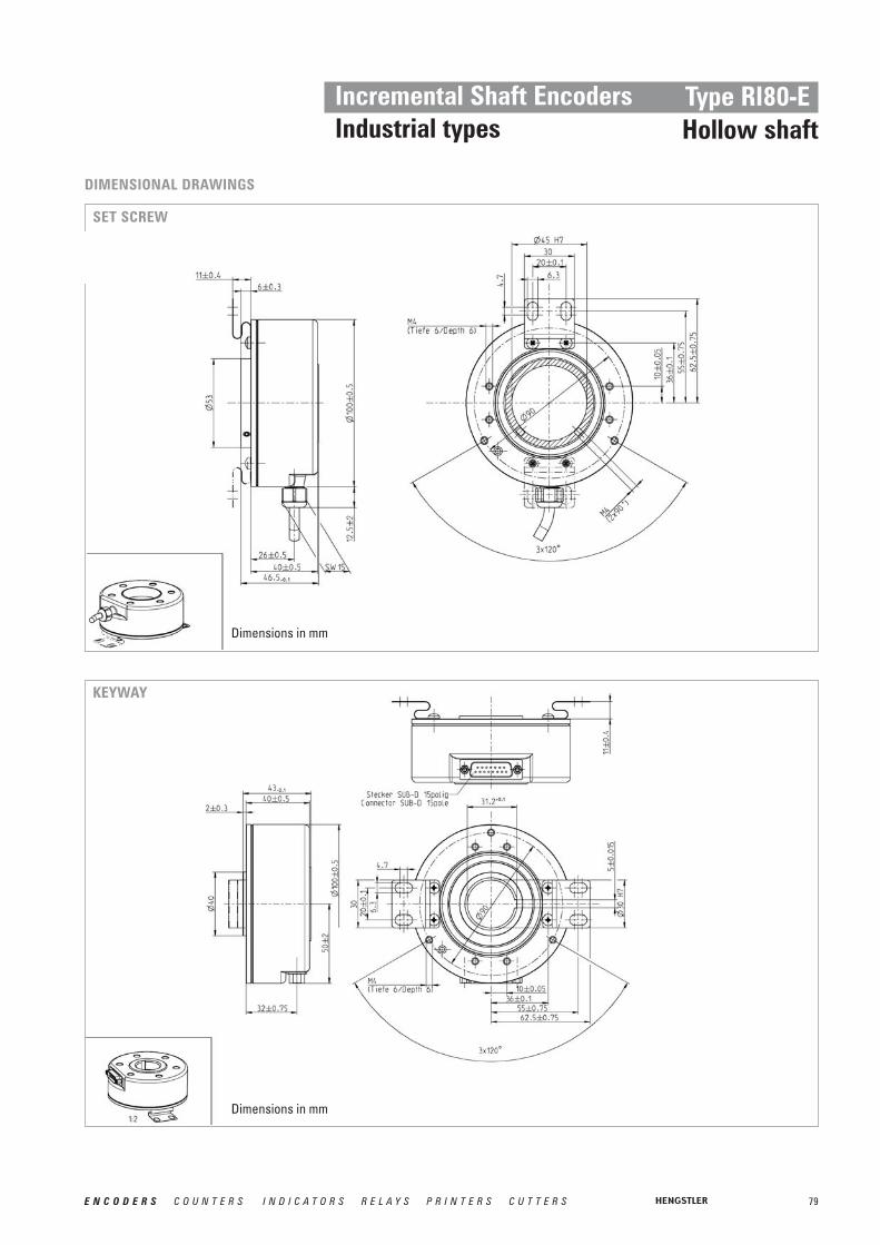
79E N C O D E R S C O U N T E R S I N D I C A T O R S R E L A Y S P R I N T E R S C U T T E R S
Incremental Shaft EncodersIndustrial types
Type RI80-EHollow shaft
SET SCREW
DIMENSIONAL DRAWINGS
KEYWAY
Dimensions in mm
Dimensions in mm

80 E N C O D E R S C O U N T E R S I N D I C A T O R S R E L A Y S P R I N T E R S C U T T E R S
ORDERING INFORMATION
Supply voltageNumber of pulsesType Model
A DC 5 VB DC 5 - 30 V
Spring tether
A singleB doubleO without
Protection
1 IP504 IP640 IP40
102420484096
RI80- E
.
Mounting/shaft
K30 Keyway/ 30mm
G30 Set screw/ 30mm
G45 Set screw/45mm
Output Connection
R RS422+ Alarm + Sense
K Push-pull 1I Push-pull
complementary 1
F Cable radial 1.5 m
F-F0 Cable radial5 m
F-K0 Cable radial 10 m
4 SUB-D 15
Incremental Shaft EncodersIndustrial types
Type RI 80-EHollow shaft
Color RS 422 Push-pull (K) Push-pull+ Alarm + Sense (R) Complement. (I)
brown Channel A Channel A Channel Agreen Channel Channel grey Channel B Channel B Channel Bpink Channel Channel red Channel N Channel N Channel Nblack Channel Channel violetwhite Sense GND Sense GNDblue Sense Vcc Sense Vccbrown/green DC 5 - 30 V DC 5 - 30 V DC 5 - 30 Vwhite/green GND GND GNDscreen 1 screen 1 screen 1 screen 1
AlarmAlarmAlarmNN
BB
AA
PIN ASSIGNMENT Cable
1 connected with encoder housing
Pin Signal12 B34 A5 GND6 +Ub7 n.c.8 screen910 N11 n.c.12 n.c.13 n.c.14 n.c.15 n.c.
N
A
BPIN ASSIGNMENT Sub-D 15 pin
1 Driver type DL, see < www.ichaus.de >

81E N C O D E R S C O U N T E R S I N D I C A T O R S R E L A Y S P R I N T E R S C U T T E R S
Incremental Shaft EncodersEconomy Types
Type PC 9/ PC 9SPanelcoders TM
■ Provides digital control inputs from operators´s panel■ Bidirectional squarewave signal outputs■ Up to 512 increments■ Continuous and reversible rotation■ Non-contacting■ Operating temperature -40 ... 100 °C
NUMBER OF PULSES
TECHNICAL DATAmechanical
TECHNICAL DATAelectrical
100 ... 512
Shaft load 1 ⁄ 8" Shaft: 4 N axial, 27 N radial1 ⁄ 4" Shaft: 4 N axial, 4 N radial
Moment of inertia 0.20 gcm2
Operating temperature -40 ... +100 °CStorage temperature -50 ... +125 °CRelative humidity 90 %, non-condensingConnection PC9: 10 pole header
PC9S: 5 pole headerRecommended mating PC9: Thomas & Betts, part number 622-1030 (on request)connectors PC9S: AMP, part number 103675-4 (on request)
Code Incremental, opticalPhasing 90° ±18° electricalSymmetry 180° ±18° electricalIndex pulse width 90° ±36° electricalSupply voltage DC 5 V ±10 %Supply current 10 mA, typicalStandy current max. 50 μA (PC9 only)Output signals min. 2.5 V high (VOH)
max. 0.5 V low (VOL)Output current PC9: 3 mA sink/source (25 °C), 2 mA (100 °C)
PC9S: 6 mA sink/source (25 °C), 4 mA (100 °C)Max. output frequency 200 kHz

82 E N C O D E R S C O U N T E R S I N D I C A T O R S R E L A Y S P R I N T E R S C U T T E R S
DIMENSIONAL DRAWINGS
OUTPUT WAVEFORMS � CONNECTIONS PC9
Incremental Shaft EncodersEconomy Types
Type PC 9/ PC 9SPanelcoders TM
2
Code 2 = 01
Code 2 = 02
Figure 1
Figure 2
ORDERING INFORMATION PC9
ACCESSORIES PC9
Code 2: OutputNumber of pulsesType
01 see figure 102 see figure 2
0 1000 1440 2000 25603000 3600 5000 512
PC9
Mounting
M 1/4’’ Shaft, sleeve bearingN 1/8’’ Shaft, ball bearings
CH N
CH N
CH N-
L = Body length
ordering code10 pole header, 30 cm ribbon cable with connector CA 0 040 012
Dimensions in inch [mm]
[ ] [ ] [ ] [ ]
[ ][ ][ ]
[ ][ ]

83E N C O D E R S C O U N T E R S I N D I C A T O R S R E L A Y S P R I N T E R S C U T T E R S
Incremental Shaft EncodersEconomy Types
Type PC 9/ PC 9SPanelcoders TM
OUTPUT WAVEFORMS � CONNECTIONS PC9S
ORDERING INFORMATION PC9SCode 2: OutputNumber of pulsesType
03 see figure 3 (no index)04 see figure 3
0 1000 1440 2000 25603000 3600 5000 512
PC9S
Mounting
M 1/4’’ Shaft, sleeve bearingN 1/8’’ Shaft, ball bearings
Code 2 = 03 / 04
Figure 3
*
* only Code 2 = 04
C H N
ACCESSORIES PC9S ordering code5 pole header, 30 cm cable with connector CA 0 050 012
+UB

84 E N C O D E R S C O U N T E R S I N D I C A T O R S R E L A Y S P R I N T E R S C U T T E R S
Incremental Shaft EncodersEconomy Types
Type RI 32
■ Replacement for type RIS and RI 31■ The economical encoder for small appliances■ High efficiency by means of ball bearing■ Small torque■ Application e.g.
- laboratory equipment- training equipment- crimping machines- tampon printing machines- miniature grinding machines
Shaft diameter 5 mm/ 6 mmAbsolute max. shaft load radial 10 N, axial 5 NAbsolute max. speed 6 000 min-1
Torque ≤ 0.05 NcmProtection class (EN 60529) Housing IP50, bearings IP40Operating temperature –10 … +60 °CStorage temperature –25 … +85 °CVibration resistance (IEC 68-2-6) 100 m/s2 (10 … 2000 Hz)Shock resistance (IEC 68-2-27) 1000 m/s2 (6 ms)Connection 1.5 m cable axial/radial 1
Material Housing: plastic; Flange: AluminiumFlange Pilot flangeWeight approx. 50 g
NUMBER OF PULSES
TECHNICAL DATAmechanical
5 / 10 / 20 / 25 / 30 / 50 / 60 / 100 / 120 / 128 / 200 / 250 / 256 / 288 / 300 / 360 / 400 / 500 / 512 / 600 / 720 / 900 / 1000 / 1024 / 1250 / 1500Other number of pulses on request
TECHNICAL DATAelectrical
General design as per DIN VDE 0160, protection class III, contamination level 2, over voltage class II
Supply voltage with push-pull (D): DC 5 V ±10 %(SELV) with push-pull (K): DC 5 V 1 ±10 % oder DC 10 - 30 V 2
Max. current w/o load 40 mA (DC 5 V), 60 mA (DC 10 V), 30 mA (DC 24 V)Standard push-pull (K, D): A, B, N, output versions 3
Alarm
2 Pole protection3 Output description and technical data see chapter “Technical basics”
1 Other cable length on request

85E N C O D E R S C O U N T E R S I N D I C A T O R S R E L A Y S P R I N T E R S C U T T E R S
Incremental Shaft EncodersEconomy Types
Type RI 32
Description (push-pull) Lead ∅ mm2 ColourDC 5 V/ 10 - 30 V 0.5 redChannel A 0.14 whiteChannel B 0.14 greenChannel N 0.14 yellowGND 0.5 black
0.14 yellow/blackAlarm
DIMENSIONAL DRAWINGS
PIN ASSIGNMENT
R for alternating bending > 100 mmR for permanent bending > 40 mm
* flattened, see dimensional drawing** not flattened 1 only with output K2 ±10 mA at DC 5 V, ±30 mA at DC 10 - 30 V
ORDERING INFORMATION
Supplyvoltage Flange, Protection, Shaft
Number of pulsesType Model
A DC 5 VE DC 10 - 30 V 1
R.11 Pilot, IP40, 6 mm *R.14 Pilot, IP40, 5 mm **
5 … 1 500RI32- 0 Standard
Output Connection
K push-pull 2short circuit proof
D push-pull DC 5 V, ±30 mA
A Cable axialB Cable radial
mounting thread M 3x4
Dimensions in mm

86 E N C O D E R S C O U N T E R S I N D I C A T O R S R E L A Y S P R I N T E R S C U T T E R S
Incremental Shaft EncodersEconomy Types
Type RI 38
■ Replacement for type RI 39■ Encoder for universal installation by means of front/back panel mounting■ High efficiency by means of ball bearing■ Small torque■ Application e.g.:
- FHP motors- laboratory equipment- labelling machines- plotters- length measuring machines
TECHNICAL DATAelectrical
General design as per DIN VDE 0160, protection class III, contamination level 2, over voltage class II
Supply voltage with push-pull (D): DC 5 V ±10 %(SELV) with push-pull (K): DC 5 V1 ±10 % oder DC 10 - 30 V1
Max. current w/o load 40 mA (DC 5 V), 60 mA (DC 10 V), 30 mA (DC 24 V)Standard push-pull (K, D): A, B, N, output versions 2
Alarm
TECHNICAL DATAmechanical
Shaft diameter 6 mmAbsolute max. shaft load radial 10 N, axial 5 NAbsolute max. speed 10 000 min-1
Torque ≤ 0.2 NcmProtection class (EN 60529) Housing IP50, bearings IP40Operating temperature –10 … +60 °CStorage temperature –25 … +85 °CVibration resistance 100 m/s2 (10 … 2000 Hz)Shock resistance 1000 m/s2 (6 ms)Connection 1.5 m cable, radial 1
Housing glassfibre reinforced plasticFlange Q = Square flangeWeight approx. 60 g
NUMBER OF PULSES 5 / 10 / 20 / 25 / 28 / 32 / 50 / 60 / 72 / 100 / 128 / 144 / 200 / 250 / 256 / 288 / 300 / 360 / 400 / 500 / 512 / 600 / 720 / 900 / 1000 / 1024Other number of pulses on request
1 Other cable length on request
1 Pole protection2 Output description and technical data see chapter “Technical basics”

87E N C O D E R S C O U N T E R S I N D I C A T O R S R E L A Y S P R I N T E R S C U T T E R S
Incremental Shaft EncodersEconomy Types
Type RI 38
Description (push-pull) Lead ∅ mm2 ColourDC 5 V/10 - 30 V 0.5 redChannel A 0.14 whiteChannel B 0.14 greenChannel N 0.14 yellowGND 0.5 black
0.14 yellow/blackAlarm
DIMENSIONAL DRAWINGS
PIN ASSIGNMENT
Dimensions in mmR for alternating bending > 100 mmR for permanent bending > 40 mm
1 only with output K2 ±10 mA at DC 5 V, ±30 mA at DC 10 - 30 V
ORDERING INFORMATION
Supplyvoltage Flange, Protection, Shaft
Number of pulsesType Model
A DC 5 VE DC 10 - 30 V 1
Q.11 Square, IP40, 6 mm5 … 1 024 RI38- O Standard
Output Connection
K push-pull 2short circuit proof
D push-pull DC 5 V, ±30 mA
B Cable radial
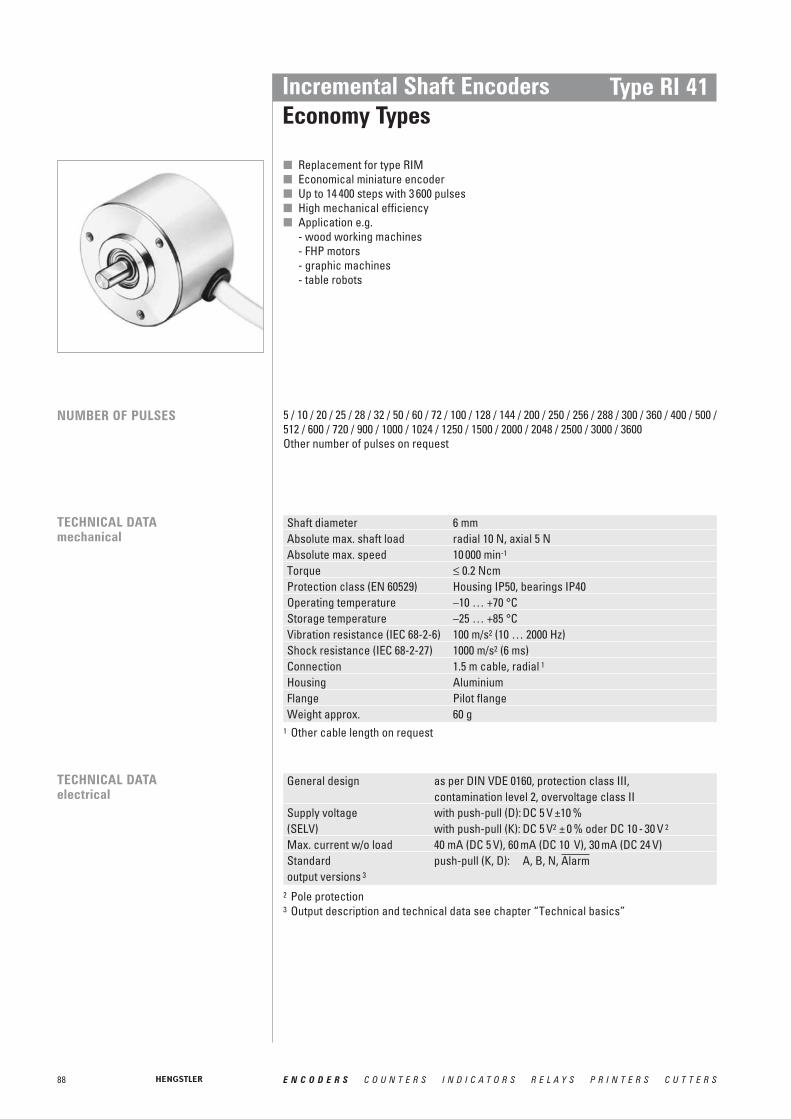
88 E N C O D E R S C O U N T E R S I N D I C A T O R S R E L A Y S P R I N T E R S C U T T E R S
Incremental Shaft EncodersEconomy Types
Type RI 41
■ Replacement for type RIM■ Economical miniature encoder■ Up to 14 400 steps with 3 600 pulses■ High mechanical efficiency■ Application e.g.
- wood working machines- FHP motors- graphic machines- table robots
NUMBER OF PULSES
TECHNICAL DATAmechanical
TECHNICAL DATAelectrical
5 / 10 / 20 / 25 / 28 / 32 / 50 / 60 / 72 / 100 / 128 / 144 / 200 / 250 / 256 / 288 / 300 / 360 / 400 / 500 /512 / 600 / 720 / 900 / 1000 / 1024 / 1250 / 1500 / 2000 / 2048 / 2500 / 3000 / 3600Other number of pulses on request
Shaft diameter 6 mmAbsolute max. shaft load radial 10 N, axial 5 NAbsolute max. speed 10 000 min-1
Torque ≤ 0.2 NcmProtection class (EN 60529) Housing IP50, bearings IP40Operating temperature –10 … +70 °CStorage temperature –25 … +85 °CVibration resistance (IEC 68-2-6) 100 m/s2 (10 … 2000 Hz)Shock resistance (IEC 68-2-27) 1000 m/s2 (6 ms)Connection 1.5 m cable, radial 1
Housing AluminiumFlange Pilot flangeWeight approx. 60 g
General design as per DIN VDE 0160, protection class III, contamination level 2, overvoltage class II
Supply voltage with push-pull (D): DC 5 V ±10 %(SELV) with push-pull (K): DC 5 V2 ± 0 % oder DC 10 - 30 V 2
Max. current w/o load 40 mA (DC 5 V), 60 mA (DC 10 V), 30 mA (DC 24 V)Standard push-pull (K, D): A, B, N, output versions 3
Alarm
1 Other cable length on request
2 Pole protection3 Output description and technical data see chapter “Technical basics”

89E N C O D E R S C O U N T E R S I N D I C A T O R S R E L A Y S P R I N T E R S C U T T E R S
Incremental Shaft EncodersEconomy Types
Type RI 41
Description (push-pull) Lead ∅ mm2 ColourDC 5 V/10 - 30 V 0.5 redChannel A 0.14 whiteChannel B 0.14 greenChannel N 0.14 yellowGND 0.5 black
0.14 yellow/blackscreen 1 screen 1
Alarm
DIMENSIONAL DRAWINGS
PIN ASSIGNMENT
1 not connected with encoder housing
R for alternating bending > 100 mmR for permanent bending > 40 mm
1 only with output K2 ±10 mA at DC 5 V, ±30 mA at DC 10 - 30 V
ORDERING INFORMATION
Supplyvoltage Flange, Protection, Shaft
Number of pulsesType Model
A DC 5 VE DC 10 - 30 V 1
R.11 Pilot, IP40, 6 mm5 … 3 600 RI41- O Standard
Output Connection
K push-pull 2short circuit proof
D push-pull DC 5 V, ±30 mA
B Cable radial
mou
ntin
g th
read
M 3
xM3
Dimensions in mm

90 E N C O D E R S C O U N T E R S I N D I C A T O R S R E L A Y S P R I N T E R S C U T T E R S
Incremental Shaft EncodersEconomy Types
Type RI 42
■ Economy encoder■ High protection IP65■ Push-pull or NPN-O.C.■ Applications, e.g.
- textile machinery
NUMBER OF PULSES
TECHNICAL DATAmechanical
TECHNICAL DATAelectrical
5 / 10 / 20 / 25 / 28 / 32 / 50 / 60 / 72 / 100 / 128 / 144 / 200 / 250 / 256 / 288 / 300 / 360 / 400 / 500 /512 / 600 / 720 / 900 / 1000 / 1024 Other number of pulses on request
Shaft diameter 6 mmAbsolute max. shaft load radial 10 N, axial 5 NAbsolute max. speed 10 000 min-1
Torque ≤ 1 NcmProtection class (EN 60529) Housing IP65, bearings IP64Operating temperature 0 … +60 °CStorage temperature –25 … +85 °CVibration resistance (IEC 68-2-6) 100 m/s2 (10 … 2000 Hz)Shock resistance (IEC 68-2-27) 1000 m/s2 (6 ms)Connection 1.5 cable axial 1
Material Housing: plastic, Flange: aluminiumFlange Pilot flangeWeight approx. 75 g
General design as per DIN VDE 0160, protection class III, contamination level 2, overvoltage class II
Supply voltage with push-pull (D): DC 5 V ±10 %(SELV) with push-pull (K): DC 5 V 1 ±10 % oder DC 10 - 30 V 1
with push-pull complementary (I): DC 10 - 30 V 1
at NPN-O.C. (S): DC 10 - 24 V 1
Max. current w/o load 40 mA (DC 5 V), 30 mA (DC 24 V) with push-pull (K,I)40 mA (DC 24 V), bei NPN-O.C. (S)
Standard push-pull2 / push-pull complementary 2 /NPN-O.C. 3
output versions
1 Other cable length on request
1 Pole protection2 Output description and technical data see chapter “Technical basics”3 NPN-O.C. with internal pull-up resistor = 10 KΩ , max. pulse frequency = 50 KHz,
max. output lead = ± 30 mA, tolerance ± 30° electrical, delay time 4μs
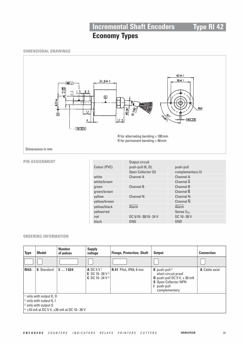
91E N C O D E R S C O U N T E R S I N D I C A T O R S R E L A Y S P R I N T E R S C U T T E R S
Incremental Shaft EncodersEconomy Types
Type RI 42
DIMENSIONAL DRAWINGS
PIN ASSIGNMENT Output circuitColour (PVC) push-pull (K, D), push-pull
Open Collector (S) complementary (I)white Channel A Channel Awhite/brown Channel green Channel B Channel Bgreen/brown Channel yellow Channel N Channel Nyellow/brown Channel yellow/blackyellow/red Sense VCC
red DC 5/10 - 30/10 - 24 V DC 10 - 30 Vblack GND GND
AlarmAlarmN
B
A
R for alternating bending > 100 mmR for permanent bending > 40 mm
1 only with output K, D2 only with output K, I3 only with output S4 ±10 mA at DC 5 V, ±30 mA at DC 10 - 30 V
ORDERING INFORMATION
Supplyvoltage Flange, Protection, Shaft
Number of pulsesType Model
A DC 5 V 1E DC 10 - 30 V 2C DC 10 - 24 V 3
R.41 Pilot, IP64, 6 mm5 … 1 024 RI42- 0 Standard
Output Connection
K push-pull 4short circuit proof
D push-pull DC 5 V, ± 30 mAS Open Collector NPNI push-pull
complementary
A Cable axial
Dimensions in mm

92 E N C O D E R S C O U N T E R S I N D I C A T O R S R E L A Y S P R I N T E R S C U T T E R S
Incremental Shaft EncodersExplosion-proof encoders
Type RX 70 / 71TI
1 / 2 / 3 / 4 / 5 / 10 / 15 / 20 / 25 / 30 / 35 / 40 / 45 / 50 / 60 / 64 / 70 / 72 / 80 / 100 / 125 / 128 /144 / 150 / 180 / 200 / 230 / 250 / 256 / 300 / 314 / 350 / 360 / 375 / 400 / 460 / 480 / 500 / 512 / 600 / 625 / 635 / 720 / 750 / 900 / 1000 / 1024 / 1200 / 1250 / 1500 / 1600 / 1800 / 2000 / 2048 / 2500 / 3000 / 3480 / 3600 / 3750 / 3968 / 4000 / 4096 / 4800 / 5000 / 5400 / 6000 / 7200 / 7680 / 8000 / 8192 / 9000 / 10000Other number of pulses on request
NUMBER OF PULSES
■ Encoder for explosion group II■ Highest working reliability■ Application e.g.:
- enamelling production lines- surfacing machines- bottling machines- mixers- silo works
■ For absolute explosion-proof encoders, see "Absolute Encoders Type AX 70 / 71"RX 70
RX 71 Stainless steel
EX-CLASSIFICATION
T6 = Highest permissible surface temperature +85°C (max. speed = 6000 U/min-1)T4 = Highest permissible surface temperature +130°C(max. speed = 10000 U/min-1)
II 2 G/D E Ex d II C T6/T4 IP65/ IP66 135°C res. 85°C
Temperature class T4 resp. T6*
Gas group C (e.g. methane; ignition energy < 60μJ)
Explosion group ll
Explosion proof enclosure
Explosion-proof operating material
Build to European specifications
For use in areas with gas, vapours, mist, cloud of dust
Category 2
Device group llI (all area expect mining)
Explosion proof enclosure with Declaration of Conformity
The incremental shaft encoder is available in explosion proof design with explosion proof enclosure “d” under RX 70 and RX 71 (stainless steel). The PTB has assured with the Declaration of Conformity that the RX 70 / 71 meets the requirements of safety and health according to EN 50014 and EN 50018. Therefore it is approved in explosive areas, code „Ex ll 2 G/D E Ex d ll C T4/T6 IP65/ IP66 135°C resp. 85°C“.For applications under tough environmental conditions and food industry the stainless steel version RX 71 is available.
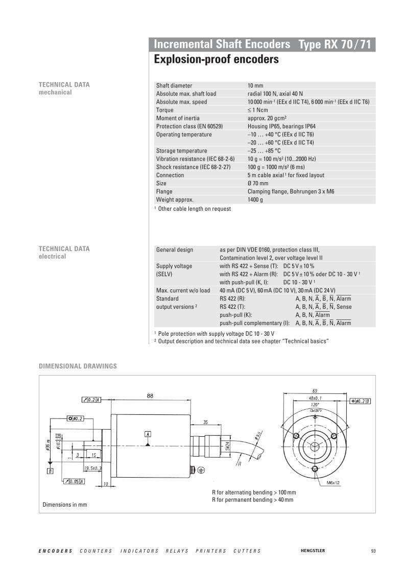
93E N C O D E R S C O U N T E R S I N D I C A T O R S R E L A Y S P R I N T E R S C U T T E R S
Incremental Shaft EncodersExplosion-proof encoders
Type RX 70 / 71
TECHNICAL DATAelectrical
General design as per DIN VDE 0160, protection class III, Contamination level 2, over voltage level II
Supply voltage with RS 422 + Sense (T): DC 5 V ± 10 %(SELV) with RS 422 + Alarm (R): DC 5 V ± 10 % oder DC 10 - 30 V 1
with push-pull (K, I): DC 10 - 30 V 1
Max. current w/o load 40 mA (DC 5 V), 60 mA (DC 10 V), 30 mA (DC 24 V)Standard RS 422 (R): A, B, N, , , , output versions 2 RS 422 (T): A, B, N, , , , Sense
push-pull (K): A, B, N, push-pull complementary (I): A, B, N, , , , AlarmNBA
AlarmNBA
AlarmNBA
DIMENSIONAL DRAWINGS
Shaft diameter 10 mmAbsolute max. shaft load radial 100 N, axial 40 NAbsolute max. speed 10 000 min-1 (EEx d IIC T4), 6 000 min-1 (EEx d IIC T6)Torque ≤ 1 NcmMoment of inertia approx. 20 gcm2
Protection class (EN 60529) Housing IP65, bearings IP64Operating temperature –10 … +40 °C (EEx d IIC T6)
–20 … +60 °C (EEx d IIC T4)Storage temperature –25 … +85 °CVibration resistance (IEC 68-2-6) 10 g = 100 m/s2 (10...2000 Hz)Shock resistance (IEC 68-2-27) 100 g = 1000 m/s2 (6 ms)Connection 5 m cable axial 1 for fixed layoutSize Ø 70 mmFlange Clamping flange, Bohrungen 3 x M6Weight approx. 1400 g
TECHNICAL DATAmechanical
1 Other cable length on request
1 Pole protection with supply voltage DC 10 - 30 V2 Output description and technical data see chapter “Technical basics”
R for alternating bending > 100 mmR for permanent bending > 40 mm
Dimensions in mm

94 E N C O D E R S C O U N T E R S I N D I C A T O R S R E L A Y S P R I N T E R S C U T T E R S
Incremental Shaft EncodersExplosion-proof encoders
Type RX 70 / 71TI
PIN ASSIGNMENT Cable OutputColour No. RS 422+ RS 422+ push-pull push-pull
Sense (T) Alarm (R) (K) complementary (I)brown/green 12 DC 5 V DC 5 / 10 - 30 V DC 10 - 30 V DC 10 - 30 Vwhite/green 11 GND GND GND GNDblue 10 Sense VCC
white 9 Sense GND brown 1 Channel A Channel A Channel A Channel Agreen 2 Channel Channel Channel grey 3 Channel B Channel B Channel B Channel Bpink 4 Channel Channel Channel red 5 Channel N Channel N Channel N Channel Nblack 6 Channel Channel Channel violet 7screen Cable screen connected to housingScrew terminal for additional connection of an earth conductor
AlarmAlarmAlarmNNN
BBB
AAA
1 with output T, R2 with output K, I, R
ORDERING INFORMATION
Supplyvoltage Flange, Protection, Shaft
Number of pulsesType Model
A DC 5 V 1E DC 10 - 30 V 2
K.42 Clamping, IP64, 10 mm1 … 10 000RX70-T I Incremental
Output Connection
K push-pullshort circuit proof
T RS 422 + SenseI push-pull complementaryR RS 422 + Alarm
A PVC cable axial (5m)
1 with output T, R2 with output K, I, R
Supplyvoltage Flange, Protection, Shaft
Number of pulsesType Model
A DC 5 V 1E DC 10 - 30 V 2
K.42 Clamping, IP64, 10 mm1 … 10 000increments
RX71-TStainlesssteel
I Incremental
Output Connection
K push-pullshort circuit proof
T RS 422 + SenseI push-pull complementaryR RS 422 + Alarm
A PVC cable axial (5m)

95E N C O D E R S C O U N T E R S I N D I C A T O R S R E L A Y S P R I N T E R S C U T T E R S
General design as per DIN VDE 0160, protection class III, Contamination level 2, over voltage level II
Supply voltage with RS 422 + Sense (T): DC 5 V ± 10 %(SELV) with RS 422 + Alarm (R): DC 5 V ± 10 % oder DC 10 - 30 V 2
with push-pull (K, I): DC 10 - 30 V 2
Max. current w/o load 40 mA (DC 5 V), 60 mA (DC 10 V), 30 mA (DC 24 V)Standard RS 422 (R): A, B, N, , , , output versions 3 RS 422 (T): A, B, N, , , , Sense
push-pull (K): A, B, N, push-pull complementary (I): A, B, N, , , , AlarmNBA
AlarmNBA
AlarmNBA
Incremental Shaft EncodersStainless steel encoders
Type RI 59
1 / 2 / 3 / 4 / 5 / 10 / 15 / 20 / 25 / 30 / 35 / 40 / 45 / 50 / 60 / 64 / 70 / 72 / 80 / 100 / 125 / 128 / 144 / 150 / 180 / 200 / 230 / 250 / 256 / 300 / 314 / 350 / 360 / 375 / 400 / 460 / 480 / 500 / 512 / 600 / 625 / 635 / 720 / 750 / 900 / 1000 / 1024 / 1200 / 1250 / 1500 / 1600 / 1800 / 2000 / 2048 / 2500 / 3000 / 3480 / 3600 / 3750 / 3968 / 4000 / 4096 / 4800 / 5000 / 5400 / 6000 / 7200 / 7680 / 8000 / 8192 / 9000 / 10000Other number of pulses on requestPreferably available versions are printed in bold type.
Shaft diameter 9.52 mm /10 mmAbsolute max. shaft load radial 60 N / axial 40 NAbsolute max. speed 10 000 min-1
Torque ≤ 1 NcmMoment of inertia approx. 20 gcm2
Protection class (EN 60529) Housing IP67, bearings IP67Operating temperature –10 … +70 °CStorage temperature –25 … +85 °CVibration resistance (IEC 68-2-6) 100 m/s2 (10 … 2000 Hz)Shock resistance (IEC 68-2-27) 1000 m/s2 (6 ms)Connection 1.5 m cable1 radial or axialHousing Stainless steel Ø 58 mmFlange Q=Square flange 63.5 x 63.5 mmWeight approx. 620 g
NUMBER OF PULSES
TECHNICAL DATAmechanical
■ Stainless steel encoder with high protection class■ High corrosion resistance■ Use in the area of food production or if sea-water proof is required■ Application e.g.:
- packing machines- bottling machines- washing plants- mixers- cranes- hoists- marine outfitters
1 Other cable length on request
TECHNICAL DATAelectrical
2 Pole protection with supply voltage DC 10 - 30 V 3 Output description and technical data see chapter “Technical basics”

96 E N C O D E R S C O U N T E R S I N D I C A T O R S R E L A Y S P R I N T E R S C U T T E R S
Incremental Shaft EncodersStainless steel encoders
Type RI 59
DIMENSIONAL DRAWINGS
R for alternating bending > 100 mmR for permanent bending > 40 mm
Connecting cable OutputColour Lead ∅ RS 422 push-pull
mm2 T and R K and Ired 0.5 DC 5/10 - 30 V DC 10 - 30 Vred/yellow 0.14 Sense VCC Sense VCC
white 0.14 Channel A Channel Awhite/brown 0.14 Channel Channel 1
green 0.14 Channel B Channel Bgreen/brown 0.14 Channel Channel 1
yellow 0.14 Channel N Channel Nyellow/brown 0.14 Channel Channel 1
black 0.5 GND GND black/yellow 0.14 /Sense GND 2
screen 3 screen 3 screen 3AlarmAlarm
NN
BB
AA
PIN ASSIGNMENT
1 only push-pull complementary (I)2 depending on ordering code3 connected with encoder housing
ORDERING INFORMATION
Supplyvoltage Flange, Protection, Shaft
Number of pulsesType Model
A DC 5 VE DC 10 - 30 V
Q.7A Square 63.5 x 63.5,IP67, 10 mm x 25
Q.7B Square 63.5 x 63.5,IP67, 9.52 mm x 25
1 … 10 000 RI59- O Standard
Output Connection
T RS 422 + SenseK push-pull
short circuit proofI push-pull
complementaryR RS 422 + Alarm
A PVC cable axialB PVC cable radial
Dimensions in mm

97E N C O D E R S C O U N T E R S I N D I C A T O R S R E L A Y S P R I N T E R S C U T T E R S
Incremental Shaft EncodersSine-wave encoders
Type RIS 58-O
■ Harmonic distortion less than 1 %■ Extended temperature range, -40 ° to +100 °C■ 500 kHz sine-wave incremental signal frequency response■ All accessible components, including the electrical connections, are resistant to com-
mon industrial coolants and lubricants■ Self-monitoring and error compensation■ Secure against short-circuit and overload■ Hot plug■ Unit is protected against overloads of 10 V/50 ms ■ 6 x 10 mm solid shaft
General design as per DIN EN 61010-1, protection class III, Contamination level 2, over voltage level III
Supply voltage DC 5 V ±10 % (SELV)Max. current w/o load max. 120 mAIncremental signal Sine - Cosine 1 VppNumber of pulses 1 000, 1 024, 2 048, 2 500
(other number of pulses on request)Absolute accuracy ±35“Repeatability ±7“Max. frequency 500 kHzReference signal > 0.4 V (1 pulse/ revolution)Connection Cable or conin, axial or radial
TECHNICAL DATAelectrical
TECHNICAL DATAmechanical
RIS 58-O with solid shaftProtection bearings IP64 (IP67 on request)Protection housing IP65 (IP67 on request)Shaft diameter 6 mmAbsolute max. speed 12 000 min-1
Torque ≤ 1 NcmAbsolute max. shaft load axial 40N / radial 60NOperating temperature -40 … +100 °CStorage temperature -20 … +80 °CWeight approx. 265 gVibration resistance (IEC 68-2-6) 100 m/s2 (10 ... 2 000 Hz)Shock resistance (IEC 68-2-27) 1 000 m/s2 (6 ms)
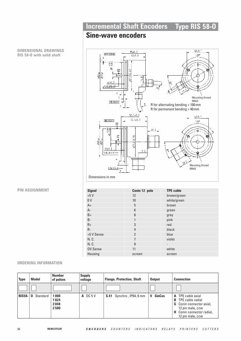
98 E N C O D E R S C O U N T E R S I N D I C A T O R S R E L A Y S P R I N T E R S C U T T E R S
Incremental Shaft EncodersSine-wave encoders
Type RIS 58-O
PIN ASSIGNMENT Signal Conin 12 pole TPE cable+5 V 12 brown/green0 V 10 white/greenA+ 5 brownA- 6 greenB+ 8 greyB- 1 pinkR+ 3 redR- 4 black+5 V Sense 2 blueN. C. 7 violetN. C. 9 -OV Sense 11 whiteHousing screen screen
DIMENSIONAL DRAWINGSRIS 58-O with solid shaft
ORDERING INFORMATION
Supplyvoltage Flange, Protection, Shaft
Number of pulsesType Model
A DC 5 V S.41 Synchro , IP64, 6 mm1 000 1 0242 0482 500
RIS58- O Standard
Output Connection
V SinCos A TPE cable axialB TPE cable radialG Conin connector axial,
12 pin male, ccwH Conin connector radial,
12 pin male, ccw
Mounting threadM4x5
Mounting threadM4x5
R for alternating bending > 100 mmR for permanent bending > 40 mm
Dimensions in mm

99E N C O D E R S C O U N T E R S I N D I C A T O R S R E L A Y S P R I N T E R S C U T T E R S
Incremental Shaft EncodersSine-wave encoders
Type RIS 58-H
General design as per DIN EN 61010-1, protection class III, Contamination level 2, over voltage level III
Supply voltage DC 5 V ±10 % (SELV)Max. current w/o load max. 120 mAIncremental signal Sine - Cosine 1 VppNumber of pulses 1 000, 1 024, 2 048 (other number of pulses on request)Absolute accuracy ±35“Repeatability ±7“Max. frequency 500 kHzReference signal > 0.4 V (1 pulse/ revolution)Connection TPE cable or conin, axial or radial
■ Harmonic distortion less than 1 %■ Extended temperature range, -40 ° to +100 °C■ 500 kHz sine-wave incremental signal frequency response■ All accessible components, including the electrical connections, are resistant
to common industrial coolants and lubricants■ Self-monitoring and error compensation■ Secure against short-circuit and overload■ Hot plug■ Unit is protected against overloads of DC 10 V/50 ms ■ 10 or 12 mm one sided open hub shaft with stator coupling
TECHNICAL DATAelectrical
TECHNICAL DATAmechanical
RIS 58-H with hollow shaftProtection bearings IP64Protection housing IP65Shaft diameter 10 mm, 12 mmMax. speed 12 000 min-1
Starting torque < 1 NcmTorque supportAxial compensations range ±1.5 mmRadial compensations range ±0.2 mmOperating temperature -40 … +100 °CStorage temperature -20 … +80 °CWeight approx. 270 gVibration resistance (IEC 68-2-6) 100 m/s2 (10 ... 2 000 Hz)Shock resistance (IEC 68-2-27) 1 000 m/s2 (6 ms)

100 E N C O D E R S C O U N T E R S I N D I C A T O R S R E L A Y S P R I N T E R S C U T T E R S
Dim. Hol low shaft Ø UnitA 10+0.012 12+0.012 mmA* 10g7 12g7 mmLmin 15 18 mmLmax 15 18 mm
Incremental Shaft EncodersSine-wave encoders
Type RIS 58-H
DIMENSIONAL DRAWINGSRIS 58-H with hollow shaft
max. shaft length
max. shaft length
PIN ASSIGNMENT Signal Conin 12 pole TPE cable+ DC 5 V 12 brown/green0 V 10 white/greenA+ 5 brownA- 6 greenB+ 8 greyB- 1 pinkR+ 3 redR- 4 black+ DC 5 V Sense 2 blueN. C. 7 violetN. C. 9 -OV Sense 11 whiteHousing screen screen
R for alternating bending > 100 mmR for permanent bending > 40 mm
A* = Diameter of connection shaftL = Inside length of connection shaft
ORDERING INFORMATION
Supplyvoltage Flange, Protection, Shaft
Number of pulsesType Model
A DC 5 V F.42 Hubshaft with tether, IP64, 10 mm
F.47 Hubshaft with tether, IP64, 12 mm
1 000 1 024 2 048
RIS58- H Hollowshaft
Output Connection
V SinCos A TPE cable axialB TPE cable radialG Conin connector axial,
12 pin male, ccwH Conin connector radial,
12 pin male, ccw
18
18
Dimensions in mm

101E N C O D E R S C O U N T E R S I N D I C A T O R S R E L A Y S P R I N T E R S C U T T E R S
Absolute Shaft Encoders
Absolute shaft encoders, also known as shaft-angle encoders, areby no means used only to detect angular positions. They are also suitable for linear movements that can be converted into rotarymovements by a toothed belt, drive pinion, or wire winch.
The special feature of absolute shaft encoders is that they assign a unique, digitally encoded signal to each individual measured increment. The method of transducing prevents erroneous readings,whether by a power failure, or by a transient malfunction. After theencoder is switched on again, or power is restored, the position canbe read out. It is not necessary to move to a reference position, as itis for shaft encoders of the incremental type.
Examples of application for absolute encoders
■ overhead support robots■ ventilation flaps■ spinning machines■ conveyor belts■ cam controllers■ injection moulding machines
■ packaging machinery■ extruders■ folding machines■ printing machines■ high lift storage systems■ stamping machines
Abso
lute
Enco
ders
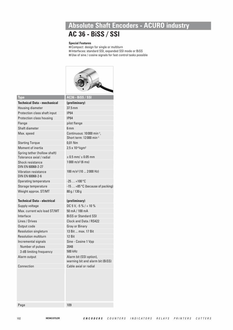
102 E N C O D E R S C O U N T E R S I N D I C A T O R S R E L A Y S P R I N T E R S C U T T E R S
Type
(preliminary)37.5 mmIP64 IP64 pilot flange6 mmContinuous: 10 000 min-1,Short term: 12 000 min-1
0,01 Nm2.5 x 10-6 kgm2
± 0.5 mm/ ± 0.05 mm1 000 m/s2 (6 ms)
100 m/s2 (10 ... 2 000 Hz)
-25 … +100 °C-15 … +85 °C (because of packing)80 g / 130 g
(preliminary)DC 5 V, -5 % / + 10 %50 mA / 100 mABiSS or Standard SSIClock and Data / RS422Gray or Binary13 Bit ... max. 17 Bit12 BitSine - Cosine 1 Vpp2048500 kHz
Alarm bit (SSI option), warning bit and alarm bit (BiSS)Cable axial or radial
AC36 - BiSS / SSI
Absolute Shaft Encoders - ACURO industryAC 36 - BiSS / SSISpecial Features■Compact design for single or multiturn■ Interfaces: standard SSI, expanded SSI mode or BiSS■Use of sine / cosine signals for fast control tasks possible
Page 109
Technical Data - mechanicalHousing diameterProtection class shaft inputProtection class housingFlangeShaft diameterMax. speed
Starting TorqueMoment of inertiaSpring tether (hollow shaft)Tolerance axial / radialShock resistanceDIN EN 60068-2-27Vibration resistanceDIN EN 60068-2-6Operating temperatureStorage temperatureWeight approx. ST/MT
Technical Data - electricalSupply voltageMax. current w/o load ST/MTInterfaceLines / DrivesOutput codeResolution singleturnResolution multiturnIncremental signals
Number of pulses3 dB limiting frequency
Alarm output
Connection

103E N C O D E R S C O U N T E R S I N D I C A T O R S R E L A Y S P R I N T E R S C U T T E R S
Technical Data - mechanicalHousing diameterProtection class shaft inputProtection class housingFlange
Shaft diameter
Max. speed
Shaft loadOperating temperatureWeight approx. ST/MT
Technical Data - electricalSupply voltage
Max. current w/o load ST/MTInterfaceResolution singleturn
Resolution multi turnOptional incremental signals
Number of pulsesAbsolute accuracyRepeat accuracy
Parameterization
Control input
Reset keyAlarm output
Status LEDConnection
Type
58 mmIP64 or IP67IP64 (IP67 optional)Synchro flange, clamping flange, hubshaft with tether, squareflangeSolid shaft 6 mm, 10 mm;Hub shaft 10 mm, 12 mmContinuous: 10 000 min-1,Short term: 12 000 min-1
axial 40 N / radial 60 N-40 … 100 °C260 g / 310 g
DC 5 V, -5 % / + 10 % or DC 10 - 30 V50 mA / 100 mABiSS or Standard SSI10-17 Bit,Gray Excess: 360, 720 steps12 BitSine - Cosine 1 Vpp2048±35“±7“Code type, direction of rotation,warning, alarm
Latch via parameterizationAlarm bit (SSI option), warning bit and alarm bit (BiSS)Green = OK.; red = alarmCable axial or radialConin axial or radialM12, 8 pole
Direction
AC 58 - BiSS / SSI
58 mmIP64 or IP67IP64 (IP67 optional)Synchro flange, clamping flange, hubshaft with tether, squareflangeSolid shaft 6 mm, 10 mm;Hub shaft 10 mm, 12 mmContinuous: 10 000 min-1,Short term: 12 000 min-1
axial 40 N / radial 60 N-40 … 100 °C350 g / 400 g
DC 10 - 30 V
200 mA / 300 mAParallel10-14 Bit,Gray Excess: 360, 720 steps12 Bit
ST: , , MT: Tristateonly with MTNPN o.c. max. 5 mA
Green = OK.; red = alarmCable axial or radial17 pole Conin axial or radial 37 pole Sub-D
TristateDirectionLatch
AC 58 - Parallel
Absolute Shaft Encoders - ACURO industryAC 58 - BiSS / SSI, ParallelSpecial Features■Compact design for single or multiturn■Aids for start-up and operation: diagnostic LED, preset key with optical response■ Interfaces: standard SSI, expanded SSI mode or BiSS■Use of sine / cosine signals for fast control tasks possible
Page 113 118

104 E N C O D E R S C O U N T E R S I N D I C A T O R S R E L A Y S P R I N T E R S C U T T E R S
Technical Data - mechanicalHousing diameterProtection class shaft inputProtection class housing
Flange
Shaft diameter
Max. speed
Shaft loadOperating temperatureWeight approx. ST/MT
Technical Data - electricalSupply voltageMax. current w/o load ST/MTInterface
Profile / Protocol
ProgrammableOutput codeTransfer mode
Baud rate
Resolution singleturn Resolution multiturnIntegrated special functions
Connection
Type
58 mmIP64 or IP67IP67
Synchro flange, clamping flange, hubshaft with tether, squareflangeSolid shaft 6 mm, 10 mm;Hub shaft 10 mm, 12 mmContinuous: 10 000 min-1,Short term: 12 000 min-1
axial 40 N / radial 60 N-40 … 85 °C350 g / 400 g
DC 10 - 30 V 220 mA / 250 mA RS 485
Profibus DP with encoder profileClass C2 (parameterizable)Resolution, preset, directionBinary
is automatically set within a rangeof 9,6 KBaud through 12 MBaud 10-14 Bit12 Bitspeed, acceleration, operating timeBus cover with: •• 3 M12 connectors •• 3 sealed cable exits•• double conin 12 pole
radial cw•• 4 pole M12 f. “tico” display
+ 2 sealed cable exits
AC 58 - Profibus
58 mmIP64 or IP67Bus cover: IP67Conin, cable: IP64 (IP67 optional)Synchro flange, clamping flange, hubshaft with tether, squareflangeSolid shaft 6 mm, 10 mm;Hub shaft 10 mm, 12 mmContinuous: 10 000 min-1,Short term: 12 000 min-1
axial 40 N / radial 60 N-40 … 85 °C350 g / 400 g
DC 10 - 30 V 220 mA / 250 mA CAN High-Speed according ISO/DIS 11898CANopen accord. DS 301 with encoder profile DSP 406Resolution, preset, directionBinaryPoll mode (only on request),Change of State (automatic ifvalue changes), cyclical withadjustable cycle timerset via DIP switch within a rangeof 10 trough 1000 Kbit/s10-14 Bit12 Bitspeed, acceleration, round axis,limit valuesBus cover with: •• 3 sealed cable exits•• double conin 9 pole
radial cwCable radial or axial Conin radial or axial, cw or ccw
AC 58 - CANopen
58 mmIP64 or IP67Bus cover: IP67Conin, cable: IP64 (IP67 optional)Synchro flange, clamping flange, hubshaft with tether, squareflangeSolid shaft 6 mm, 10 mm;Hub shaft 10 mm, 12 mmContinuous: 10 000 min-1,Short term: 12 000 min-1
axial 40 N / radial 60 N-40 … 85 °C350 g / 400 g
DC 10 - 30 V220 mA / 250 mA CAN High-Speed according ISO/DIS 11898CAN 2.0 A
Direction, limit valuesBinaryPoll mode (only on request),Change of State (automatic ifvalue changes), cyclical withadjustable cycle timerset via DIP switch within a rangeof 10 trough 1000 Kbit/s10-14 Bit12 Bit
Bus cover with: •• 3 sealed cable exits•• double conin connectors
9 pole radial cwCable radial or axialConin radial or axial, cw or ccw
AC 58 - CANLayer 2
Absolute Shaft Encoders - ACURO industryAC 58 with Fieldbus InterfacesSpecial Features■Overall length: 63 mm for singleturn, 73 mm for multiturn, including bus cover■The complete bus specific electronics is integrated in the connection cover■Option: Display "tico"■Diagnostic LEDs in the bus cover
Page 123 127 130

105E N C O D E R S C O U N T E R S I N D I C A T O R S R E L A Y S P R I N T E R S C U T T E R S
Technical Data - mechanicalHousing diameterProtection class shaft inputProtection class housing
Flange
Shaft diameter
Max. speed
Shaft loadOperating temperatureWeight approx. ST/MT
Technical Data - electricalSupply voltageMax. current w/o load ST/MTInterface
Profile / Protocol
Programmable
Output codeTransfer mode
Baud rate
Resolution singleturn Resolution multiturnConnection
Type
58 mmIP64 or IP67IP67
Synchro flange, clamping flange, hubshaft with tether, squareflangeSolid shaft 6 mm, 10 mm;Hub shaft 10 mm, 12 mmContinuous: 10 000 min-1,Short term: 12 000 min-1
axial 40 N / radial 60 N-40 … 85 °C350 g / 400 g
DC 10 - 30 V220 mA / 250 mA CAN High-Speed according ISO/DIS 11898, CAN-Specification 2.0 A (11-Bit-Identifier)DeviceNet nach Rev. 2.0, programmable encoderResolution, preset, direction
BinaryPoll mode (only on request),Change of State (automatic ifvalue changes), cyclical withadjustable cycle timerset via DIP switches to125, 250, 500 KBaud10-14 Bit12 BitBus cover with: •• 2 sealed cable exits•• 4 pole M12 f. “tico” display
+ 2 sealed cable exits •• 5 pole M12
AC 58 - DeviceNet
58 mmIP64 or IP67Bus cover: IP67Cable: IP64 (IP67 optional)Synchro flange, clamping flange, hubshaft with tether, squareflangeSolid shaft 6 mm, 10 mm;Hub shaft 10 mm, 12 mmContinuous: 10 000 min-1,Short term: 12 000 min-1
axial 40 N / radial 60 N-40 … 70 °C350 g / 400 g
DC 10-30 V220 mA / 250 mA Remote installation busInterbus, ENCOM Profile K3 (parameterizable), K2K3 = ID-Code 37K2 = ID-Code 36Direction, scaling factor,preset, offset32 Bit binary
500 KBaud according ENCOM
10-12 Bit 12 BitBus cover with: •• 3 sealed cable exits•• 4 pole M12 f. “tico” Display
+ 2 sealed cable exits•• double conin 9 poleCable 12 pole, radial and axial
AC 58 - Interbus
58 mmIP64 or IP67IP64
Synchro flange, clamping flange, hubshaft with tether, squareflangeSolid shaft 6 mm, 10 mm;Hub shaft 10 mm, 12 mmContinuous: 10 000 min-1,Short term: 12 000 min-1
axial 40 N / radial 60 N-10 … 60 °C260 g / 310 g
DC 10-30 V220 mARS485
SUCOnet-K1 or Hengstler-G1-Protocol
Binary
10 - 13 Bit12 BitCable axial/ radial
AC 58 - SUCOnet
Absolute Shaft Encoders - ACURO industryAC 58 with Fieldbus InterfacesSpecial Features■Overall length: 63 mm for singleturn, 73 mm for multiturn, including bus cover■The complete bus specific electronics is integrated in the connection cover■Option: Display "tico"■DiagnosticLEDs in the bus cover
Page 133 136 140

106 E N C O D E R S C O U N T E R S I N D I C A T O R S R E L A Y S P R I N T E R S C U T T E R S
Technical Data - mechanicalHousing diameterProtection class shaft inputProtection class housingFlange
Shaft diameter
Max. speed
Shaft loadOperating temperatureWeight approx. ST/MT
Technical Data - electricalSupply voltageMax. current w/o loadInterface Resolution singleturn Resolution multiturnParameterization
Control inputAlarm outputStatus LEDConnection
Type
58 mmIP64 or IP67IP64 (IP67 optional)Synchro flange, clamping flange, hubshaft with tether, squareflangeSolid shaft 6 mm, 10 mm;Hub shaft 10 mm, 12 mmContinuous: 10 000 min-1,Short term: 12 000 min-1
axial 40 N / radial 60 N-40 … 70 °C260 g / 310 g
DC 10 - 30 Vmax. 250 mASSI programmable10 - 17 Bit12 Bitresolution, code type, sense ofrotation, output format, warning,alarmDirection, Preset 1, Preset 2Alarm bitGreen = ok.; red = alarmCable radial or axialConin radial or axial, ccw
AC 58 - SSI Programmable
Absolute Shaft Encoders - ACURO industryAC 58 - SSI programmableSpecial Features■Compact design: 59mm length for single or multiturn■Aids for start-up and operation: diagnostic LED, preset key with optical response■Parameterization: resolution, code type, sense of rotation, output format, warning, alarm■Parameters can be stored in a non-volatile memory
Page 142
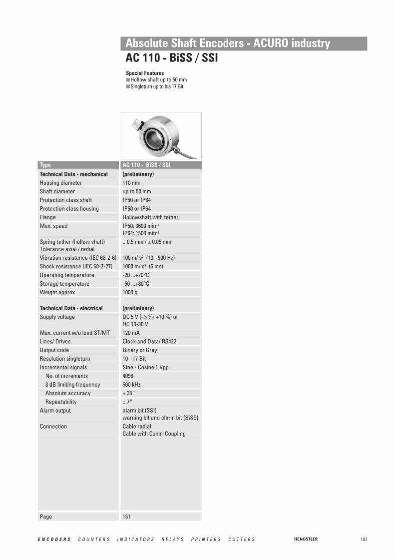
107E N C O D E R S C O U N T E R S I N D I C A T O R S R E L A Y S P R I N T E R S C U T T E R S
Technical Data - mechanicalHousing diameterShaft diameterProtection class shaftProtection class housingFlangeMax. speed
Spring tether (hollow shaft)Tolerance axial / radialVibration resistance (IEC 68-2-6)Shock resistance (IEC 68-2-27)Operating temperatureStorage temperatureWeight approx.
Technical Data - electricalSupply voltage
Max. current w/o load ST/MTLines/ DrivesOutput codeResolution singleturnIncremental signals
No. of increments3 dB limiting frequencyAbsolute accuracyRepeatability
Alarm output
Connection
Type
(preliminary)110 mm up to 50 mm IP50 or IP64IP50 or IP64Hollowshaft with tetherIP50: 3600 min-1
IP64: 1500 min-1
± 0.5 mm / ± 0.05 mm
100 m/ s2 (10 - 500 Hz)1000 m/ s2 (6 ms) -20 ...+70°C -50 ...+80°C 1000 g
(preliminary)DC 5 V (–5 %/ +10 %) or DC 10-30 V120 mAClock and Data/ RS422Binary or Gray10 - 17 BitSine - Cosine 1 Vpp4096500 kHz± 35“± 7“alarm bit (SSI), warning bit and alarm bit (BiSS)Cable radialCable with Conin-Coupling
AC 110 - BiSS / SSI
Absolute Shaft Encoders - ACURO industryAC 110 - BiSS / SSISpecial Features■Hollow shaft up to 50 mm■Singleturn up to bis 17 Bit
Page 151

108 E N C O D E R S C O U N T E R S I N D I C A T O R S R E L A Y S P R I N T E R S C U T T E R S
Absolute Shaft EncodersStainless Steel / Explosion-Proof
Special Features
Technical Data – mechanicalHousing diameterShaft diameterFlangeMax. speed
TorqueMoment or inertia Max. shaft loadVibration proof (IEC 68-2-6)Shock resistance (IEC 68-2-27)Operating temperature
Storage temperatureMaterial Shaft/ Housing
Weight approx.
Technical Data – electrical
■ ATEX certification for gas anddust explosion proof
■ EX-classification: Ex II 2 G/D E Ex d II C T4/T6
■ Same electrical performance as ACURO industry
■ Protection class up to IP67■ Diameter only 70 mm ■ Robust design■ Available with stainless steel■ Resolution up to 29 Bit
(17 Bit ST, 12 Bit MT)■ Applications:
enamelling production line,petro chemistry, bottling machines, mixers, silo works, mills
■ Interfaces: SSI, SSI programmable, Profibus, CANopen
70 mm10 mmClamping flange6 000 min -1 (T6)10 000 min -1 (T4)≤ 1 Ncmapprox. 20 gcm2
axial 40 N/ radial 100 N100 m/ s2 (10 - 500 Hz)1000 m/ s2 (6 ms)-40 ... +60 °C (T4)-40 ... +40 °C (T6)
-25 ... +80 °CAluminium (AX 70)Stainless steel (AX 71)1 000 g (AX 70), 1 900 g (AX 71)
The electrical data dependon the type of interface. Please refer to chapter
“AX 70 / AX 71”.
Type AX 70/ AX 71 (Stainless)
Page 161154
■ Compact design■ Protection class IP67■ High corrosion resistance■ Robust design■ Resolution up to 29 Bit
(17 Bit ST, 12 Bit MT)■ Connection with cable or
with bus terminal box■ Applications:
- Packaging machine for food and beverage
- Ship equipment (e.g. cranes, winches, cable laying ships)
- Offshore - Applications
10 mmSquare flange 63.5 x 63.5 mmShort term: 10 000 min-1
Continuous: 6 000 min-1
< 1 Ncmapprox. 20 gcm2
axial 40 N/ radial 60 N100 m/ s2 (10 - 500 Hz)1000 m/ s2 (6 ms)SSI, BiSS, Parallel: -40...+100°C SSI-P, Interbus: -40...+70°C Profibus, CANopen, CANlayer2,DeviceNet: -40...+ 85°C40...+ 85°C Stainless steel
AC 59 with 1.5 m cable: 700 gAC 61 with 1.5 m cable: 980 gAC 61 with bus cover (MT): 1 180 g
The electrical data dependon the type of interface.
Please refer to the specific interface chapter.
AC 59/61

109E N C O D E R S C O U N T E R S I N D I C A T O R S R E L A Y S P R I N T E R S C U T T E R S
Absolute Shaft EncodersACURO industry
Type AC 36BiSS / SSI
■ Overall length 36 mm■ For equipment engineering and industry■ Up to 17 Bit singleturn and 12 Bit multiturn■ Hollow shaft 6 mm■ +100°C operating temperature■ 10 000 rpm continous operation■ Optical encoder with a true geared multiturn■ SSI or BiSS interface■ Option Sine 1 Vpp■ 500kHz bandwidth
APPLICATIONS The AC 36 is an absolute optical encoder with a true geared multiturn, optical sensing tech-nology and 36 mm diameter. Equiped with a solid-shaft the AC 36 is mechanical compatiblewith all common inkremental encoders. The compact design allows to replace the adequate incremental encoders directly. As a result the technical facilities of absolute encoders canbe used for the first time in equipment engineering and also in medical engineering. Themechanical design consists of two ball bearings supported mechanical shaft assembly. TheAC 36 complements the ACURO-industry series with small frame sizes and the same performance as 58 mm versions.
BiSS-InterfaceUnique within his class the AC 36 provides fully digital position data up to 17 Bit (singleturn)and 12 Bit (multi-turn) over the bidirectional synchronous interface with a variable clockrate up to 10 MHz. This corresponds a singleturn resolution of more than 130 000 mesuredsteps. Backward compatibility is realized through the SSI interface together with 2048 sine-cosine periods per revolution.
Integrated diagnostic systemThe AC 36 is based on latest OptoAsic technology with an advanced diagnostic concept. Acontinous plausibility check controls the internal signal processing for each increment. A code check guarantees that the encoder signal represents bit by bit the mesured rotation.Also the operating temperature of the encoder can be measured, read out and monitored overwarn and alarm bits with 8 bit resolution (1°C). Monitoring and controlling of the operatingtemperature ensures a maximum lifetime of the LED. Eventual failures are indicated early overwarn bits.
TECHNICAL DATAmechanical
Housing diameter 37.5 mmProtection class shaft input IP64Protection class housing IP64Flange pilot flangeShaft diameter 6 mmMax. speed Continuous 10 000 min-1, short term 12 000 min-1
Starting torque 0.01 NmMoment of inertia 2.5 x 10⁻⁶ kgm2
Shock resistance DIN EN 60068-2-27 1 000 m/s2 (6 ms)Vibration resistance DIN EN 60068-2-6 100 m/s2 (10 ... 2 000 Hz)Operating temperature -25...+100 °CStorage temperature -15...+85 °C (because of packing)Weight approx. ST/MT 80 g / 130 g
PPRREELLIIMMIINNAARRYY
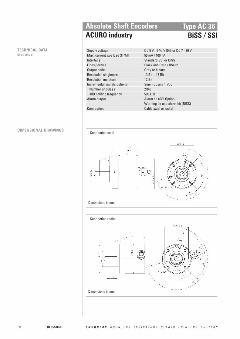
110 E N C O D E R S C O U N T E R S I N D I C A T O R S R E L A Y S P R I N T E R S C U T T E R S
Absolute Shaft EncodersACURO industry
Type AC 36BiSS / SSI
TECHNICAL DATAelectrical
Supply voltage DC 5 V, -5 % /+10% or DC 7 - 30 VMax. current w/o load ST/MT 50 mA / 100mAInterface Standard SSI or BiSSLines / drives Clock and Data / RS422Output code Gray or binaryResolution singleturn 13 Bit - 17 Bit Resolution multiturn 12 BitIncremental signals optional Sine - Cosine 1 Vpp
Number of pulses 2 0483dB limiting frequency 500 kHz
Alarm output Alarm bit (SSI Option)Warning bit and alarm bit (BiSS)
Connection Cable axial or radial
DIMENSIONAL DRAWINGSConnection axial
Connection radial
Dimensions in mm
Dimensions in mm

111E N C O D E R S C O U N T E R S I N D I C A T O R S R E L A Y S P R I N T E R S C U T T E R S
Absolute Shaft EncodersACURO industry
Type AC 36BiSS / SSI
PIN ASSIGNMENT Signal Colour cable old Colour cable old Colour cable newwith BI, SG, SB with SC
DC 5 / 7-30 V (UB) yellow/black yellow/black white0 V (UN) white/green white/green brownClock white white yellow
brown brown greenData black black pink
violet violet greyA nc. green white/green 1
nc. yellow brown/green 1
B nc. blue red/blue 1
nc. red grey/pink 1
DC 5 V Sensor nc. red/black violet 1
0 V Sensor nc. brown/green black 1
B
A
Data
Clock
ORDERING INFORMATION
Supply voltage Flange, Protection, ShaftResolution Interface ConnectionType
A DC 5 VE DC 7 - 30 V
R.41 Clamping ring, IP64, solid shaft 6 mm
0012 12 Bit ST0013 13 Bit ST0014 14 Bit ST0017 17 Bit ST1213 12 Bit MT+13 Bit ST1217 12 Bit MT+17 Bit ST
(BiSS)
AC 36 SC SSI Gray + SinCos 1 Vpp
BI BiSSSG SSI graySB SSI binary
A Cable axial 1.5 m B Cable radial 1.5 m
/
1 only with “SC”

112 E N C O D E R S C O U N T E R S I N D I C A T O R S R E L A Y S P R I N T E R S C U T T E R S
ElectricalSupply DC 5 VSupply DC 10-30 VPreset key with LED (not IP67)Diagnostics
- LED indication- Warning- Alarm bit- Alarm output- Temperature measurement
Connection for "tico"Parameterization (PC,with Acuro Soft)Parameterization (Bus)Inputs
- Latch- Direction- 2 lines for present input- Tristate
Special Functions- Speed- Acceleration- On time- Round axis- Limit values
Optional 1 VppConnectionsBus cover, 3 cable screwBus cover, 2 cable screw+M12 for "tico"Bus cover, 2 cable screwBus cover, 2 Conin 9-poleBus cover, 2 Conin 12-poleBus cover, 3 M12 4-poleBus cover, 1 M12 5-poleCable axial / radialCable ax /rad 0.1 m+37-pole Sub-DConin 12-pole ax/rad CW/CCWConin 17-pole ax/rad CW/CCWM12 8-pole ax/radMechanicalSynchro fl., shaft 6x10 mm, IP64 or IP67Clamping fl., shaft 10x19.5 mm, IP64 or IP67Clamping fl., shaft 9.52x19.5 mm, IP64 or IP67Hubshaft with tether 10 mm, IP64Hubshaft with tether 12 mm, IP64Hubshaft with tether 12,7 mm, IP64Square flange, 63.5 mm, shaft 9.52x19.5 mm, IP64 or IP67Square flange, 63.5 mm,shaft 10 x 19.5 mm, IP64 or IP67
Absolute Shaft Encoders ACURO industryOverview Functions and Versions AC 58
•••
•
(Option)
(Option)
(Option)
•
•
•
•
•
•
•••••••
•
•••
•••
(Option)
•
•
•
•
•
•
•
•••••••
•
(Option)
•only LED
•
••
•
•
•
•••••••
•
•
•••
•
•
•••
••
••
•
•••••••
•
•
•
•
•
•
••
•
•••••••
•
•
•
•
•
•
•
•
•••••••
•
•
•
•
•
••
••
•
•
•
•••••••
•
•
•
•
•
•
•••••
••
•
•
•
•••••••
•
SSI BiSS Parallel ST Profibus DeviceNet Interbus CAN CANopen
•
•
•
•••••••
•
SUCOnet
••
•
••
•
•
•
•••••••
•
SSI para.
(Option)
••
•
•
••
•
••
•••••••
•
Parallel MT

113E N C O D E R S C O U N T E R S I N D I C A T O R S R E L A Y S P R I N T E R S C U T T E R S
Absolute Shaft EncodersACURO industry
Type AC 58BiSS / SSI
■ Compact design: 50mm length forsingle or multiturn
■ Aids for start up and operation: diagnostic LED, preset key withoptical response, status information
■ Use of sine/ cosine signals forfast control task possible
■ Control input: Direction■ Resolution up to 29 Bit
TECHNICAL DATAmechanical
Housing diameter 58 mmProtection class shaft input IP64 or IP67Protection class housing IP64 (IP67 optional)Flange Synchro flange, clamping flange,
hubshaft with tether, square flangeShaft diameter Solid shaft 6 mm, 10 mm; Hub shaft 10 mm, 12 mmMax. speed Continuous 10 000 min-1, short term 12 000 min-1
Starting torque ≤ 0.01 NmMoment of inertia 3.8 x 10⁻⁶ kgm2
Spring tether (hollow shaft)Tolerance axial ±1.5 mmTolerance radial ±0.2 mmMax. shaft load axial 40 N / radial 60 NShock resistance DIN EN 60068-2-27 1 000 m/s2 (6ms)Vibration resistance DIN EN 60068-2-6 100 m/s2 (10 ... 2.000 Hz)Operating temperature -40 ... 100 °CStorage temperature -25 ... 85 °C (because of packing)Weight approx. ST/MT 260 g / 310 g
TECHNICAL DATAelectrical
Supply voltage DC 5 V, -5 % / +10 % or DC 10–30 VMax. current w/o load ST/MT 50 mA / 100 mAInterface Standard SSI or BiSSLines / drives Clock and Data / RS422Output code Binary or Gray parameterization with ACURO softLinearity ± ½ LSB (± 1 LSB for resolution > 13 Bit)Resolution singleturn 10–17 Bit , Gray Excess: 360, 720 incrementsResolution multiturn 12 BitIncremental signals optional Sine - Cosine 1 Vpp
Number of pulses 2 0483dB limiting frequency 500 kHzAbsolute accuracy ±35´´Repeatability ±7´´
Parameterization Code type, direction, warning, alarmwith Acuro softControl inputReset key Disable via parameterizationAlarm output Alarm bit (SSI Option),
warning bit and alarm bit (BiSS)Status LED Green = ok.; red = alarmConnection Cable or conin, axial or radial
Direction
Synchro flange Hub shaft
DIMENSIONAL DRAWINGS see chapter “Dimensional drawings ACURO industry”, starting page 146

T19
114 E N C O D E R S C O U N T E R S I N D I C A T O R S R E L A Y S P R I N T E R S C U T T E R S
Resolution
9 Bit 1
10 Bit 1
11 Bit 1
12 Bit 1
13 Bit 1
14 Bit 1
15 Bit 1
16 Bit 1
17 Bit 1
Data bitsT1 ... T9S8 ... S0S9 ... S1S10 ... S2S11 ... S3S12 ... S4S13 ... S5S14 ... S6S15 ... S7S16 ... S8
T100S0S1S2S3S4S5S6S7
T1100S0S1S2S3S4S5S6
T12000S0S1SS2S3S4S5
T130000S0S1S2S3S4
T1400000S0S1S2S3
T15W 2
W 2
W 2
W 2
W 2
0S0S1S2
T16
W 2
0S0S1
T17
W 2
0S0
T18
W 2
0
T19
W 2
Resolution
24 Bit 1
25 Bit 1
26 Bit 1
24 Bit + P 3
24 Bit + A 4
24 Bit +P 3+A4
Data bitsT1 ... T12M11 ... M0M11 ... M0M11 ... M0
M11 ... M0M11 ... M0M11 ... M0
T13 ... T21S11 ... S2S12 ... S3S13 ... S4
S11 ... S2S11 ... S2S11 ... S2
T22S1S2S3
S1S1S1
T23S0S1S2
S0S0S0
T240S0S1
PAP
T25W 2
0S0
00A
W 2
0
W 2
W 2
0
W 2
W 2
Absolute Shaft EncodersACURO industry
Type AC 58BiSS / SSI
The max. data transfer rate depends on the cable length. For Clock / and Data / please use twisted pairs. Use shielded cable.DataClock
Cable length Frequency< 50 m < 400 kHz< 100 m < 300 kHz< 200 m < 200 kHz< 400 m < 100 kHz
RECOMMENDED DATA TRANSFER RATE WITH SSI
DATA FORMATsingleturn
DATA FORMATMultiturn
S0 ... S16 Data bits for resolution per revolutionM0 ... M11 Data bits for number of revelutions (only for multiturn) 1 Options (Parity bit, alarm and parity bit, zero bit) on request2 W: from this data bit on the data iteration for multiplex starts3 Parity bit :Even Parity (The parity bit expands the data bits to an even nummber of 1-bits).
(Option)4 Alarm bit: is set to "1" when over temperature, under temperature, disc breakage
and defect LED
Resolution
9 Bit + P 3
9 Bit + A 4
9 Bit + P 3 + A 4
13 Bit + P 3
13 Bit + A 4
13 Bit +P 3+A4
Data bitsT1 ... T9S8 ... S0S8 ... S0S8 ... S0
S12 ... S4S12 ... S4S12 ... S4
T10000
S3S3S3
T11000
S2S2S2
T12000
S1S1S1
T13PAA
S0S0S0
T1400P
PAA
T15W 2
W 2
0
00P
T16
W 2
W 2
W 2
0
T17
W 2
T18
Examples for data format 9 Bit and 13 Bit with the optional bits alarm und parity
Example for data format 24 Bit with the optional bits alarm und parity

115E N C O D E R S C O U N T E R S I N D I C A T O R S R E L A Y S P R I N T E R S C U T T E R S
Absolute Shaft EncodersACURO industry
Type AC 58BiSS / SSI
Cable Conin Signalbrown 3 1 0 V (supply voltage)pink 2 Datayellow 3 Clock
4 N.C.blue 5 1
red 6 N.C.violet 7 N.C.white 3 8 DC 5/10 - 30 V
9 N.C.grey 10green 11black 12 0 V-signal output 2
ClockData
Direction
Synchronous readout of the encoder data is according to the clock rate given by theSSI-counterpart.The number of clock rates is determined by the type of encoder (singleturn resp. multiturn) and the configuration of the spe-cial Bits as defined.For multiple transactions (the stored valueis readout several times successively) afixed clock rate per transaction must bekept (for singleturn 13 resp. 14 clocks, formultiturn 25 resp. 26 clocks).• In the rest position, when the last clock
brush has passed by more than 30μs, the data output is logically at ”1“.
• With the first descending clock edge theencoder data and the special bits are loaded in the shift register of the encoder interface.
1 : + UB or unconnected = ascending code values with rotation cw0 V = descending code values with rotation cw
2 Connected with 0 V in the encoder. Use this output to lay Direction on logical "0" if requi-red.3 use only the thin wires (∅ = 0.14 mm)
Direction
SYNCHRONOUS-SERIAL TRANSFER (SSI)
• With each ascending clock edge the databits are serially readout, beginning with the MSB.
• At the end of the data transfer the data output is set to logically ”0“ for approx. 20μs. If within these 20μs a further clock brush reaches the encoder interface, the already transferred data is readout once again.This multiple transfer of the same data makes it possible to recognize transfer errors.
• After the 20μs the data output goes to its rest position, logically ”1“. Subsequently new encoder data can be readout.
PIN ASSIGNMENTCable & Conin
PIN ASSIGNMENT M12
M12 Plug-in connector 8 poleColour Pin Signalwhite 1 DC 10 - 30 Vbrown 2 0 V
3 N.C.green 4pink 5 Datayellow 6 Clockblue 7 1
grey 8 DataDirection
Clock
1 : + UB or unconnected = ascending code values with rotation cw0 V = descending code values with rotation cw
Direction
View on connector

116 E N C O D E R S C O U N T E R S I N D I C A T O R S R E L A Y S P R I N T E R S C U T T E R S
Absolute Shaft EncodersACURO industry
Type AC 58BiSS / SSI
Ordering codePosition indicationsigno-SSI see chapter “Accessories”
(page 236)
Mounting eccentric for synchronous flange 0 070 655Diaphragm coupling (hub 6/6 mm) 3 520 081Diaphragm coupling (hub 10/10 mm) 3 520 088
ACCESSORIES
Mating connector: 12 pin ConinOrdering code
clockwise (C,D) 3 539 202counter clockwise (G,H) 3 539 229cable not made up with connector see chapter “Accessories”(page 236)
(ordering code 3 280 220)
Extension cable with plug Ordering codeclockwise 3 m 1 542 003(C,D) 5 m 1 542 004
10 m 1 542 005counter clockwise 3 m 1 542 010(G,H) 5 m 1 542 011
10 m 1 542 012
Ordering codeM12 plug 3 539 597
Extension cable with M12 plug Ordering code3 m 1 565 3295 m 1 565 33010 m 1 565 331
Ordering codeACURO soft, PC connecting cable, incl. on requestpower pack 230 VA, for CONIN 12 pole, CCW (suited for supply voltage E and connection G or H)
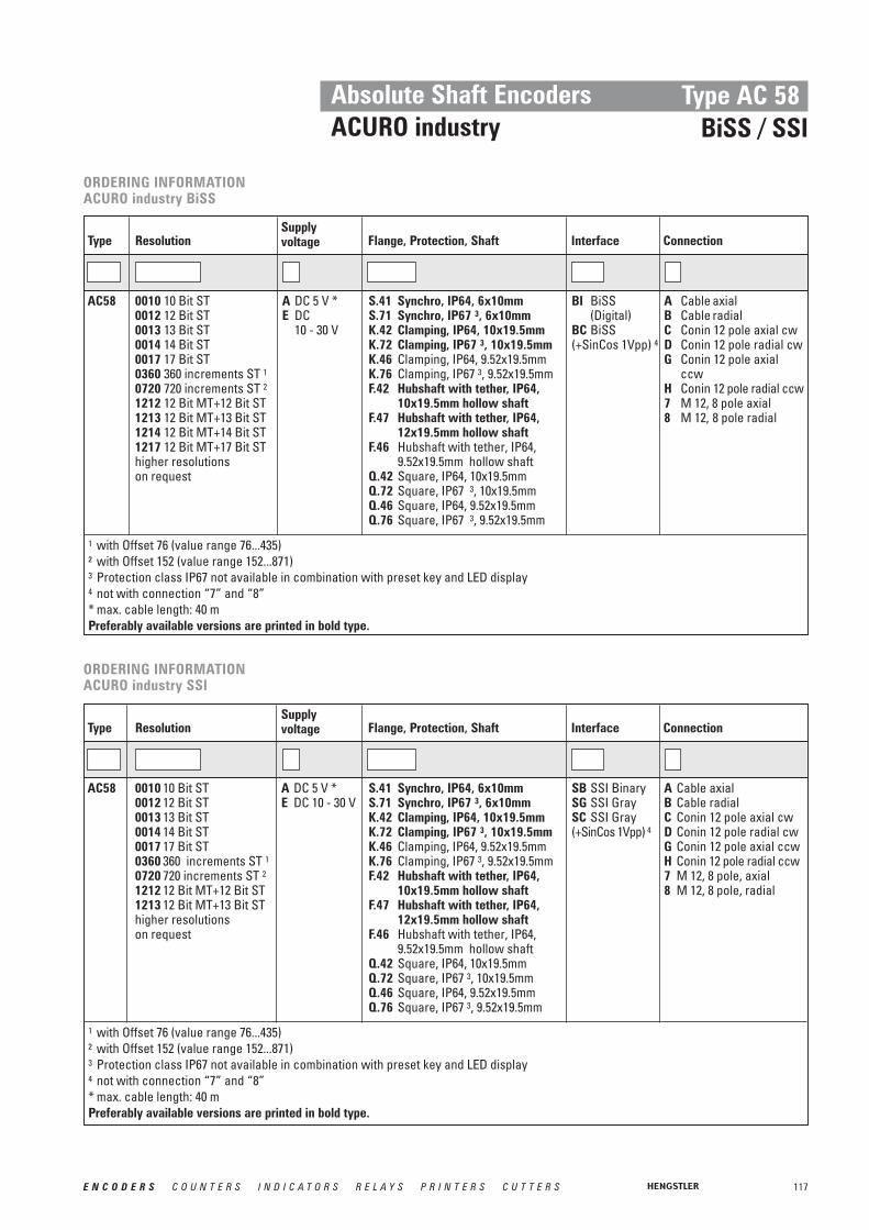
117E N C O D E R S C O U N T E R S I N D I C A T O R S R E L A Y S P R I N T E R S C U T T E R S
Absolute Shaft EncodersACURO industry
Type AC 58BiSS / SSI
ORDERING INFORMATIONACURO industry BiSS
Supplyvoltage Flange, Protection, ShaftResolution Interface ConnectionType
A DC 5 V *E DC
10 - 30 V
S.41 Synchro, IP64, 6x10mm S.71 Synchro, IP67 3, 6x10mm K.42 Clamping, IP64, 10x19.5mm K.72 Clamping, IP67 3, 10x19.5mm K.46 Clamping, IP64, 9.52x19.5mmK.76 Clamping, IP67 3, 9.52x19.5mmF.42 Hubshaft with tether, IP64,
10x19.5mm hollow shaft F.47 Hubshaft with tether, IP64,
12x19.5mm hollow shaft F.46 Hubshaft with tether, IP64,
9.52x19.5mm hollow shaftQ.42 Square, IP64, 10x19.5mmQ.72 Square, IP67 3, 10x19.5mmQ.46 Square, IP64, 9.52x19.5mmQ.76 Square, IP67 3, 9.52x19.5mm
0010 10 Bit ST0012 12 Bit ST0013 13 Bit ST0014 14 Bit ST0017 17 Bit ST0360 360 increments ST 10720 720 increments ST 21212 12 Bit MT+12 Bit ST1213 12 Bit MT+13 Bit ST1214 12 Bit MT+14 Bit ST1217 12 Bit MT+17 Bit SThigher resolutionson request
AC58 BI BiSS (Digital)
BC BiSS (+SinCos 1Vpp) 4
A Cable axialB Cable radial C Conin 12 pole axial cwD Conin 12 pole radial cwG Conin 12 pole axial
ccwH Conin 12 pole radial ccw7 M 12, 8 pole axial8 M 12, 8 pole radial
1 with Offset 76 (value range 76...435)² with Offset 152 (value range 152...871)3 Protection class IP67 not available in combination with preset key and LED display4 not with connection “7” and “8”* max. cable length: 40 mPreferably available versions are printed in bold type.
ORDERING INFORMATIONACURO industry SSI
Supply voltage Flange, Protection, ShaftResolution Interface ConnectionType
A DC 5 V *E DC 10 - 30 V
S.41 Synchro, IP64, 6x10mm S.71 Synchro, IP67 3, 6x10mm K.42 Clamping, IP64, 10x19.5mm K.72 Clamping, IP67 3, 10x19.5mm K.46 Clamping, IP64, 9.52x19.5mmK.76 Clamping, IP67 3, 9.52x19.5mmF.42 Hubshaft with tether, IP64,
10x19.5mm hollow shaft F.47 Hubshaft with tether, IP64,
12x19.5mm hollow shaft F.46 Hubshaft with tether, IP64,
9.52x19.5mm hollow shaftQ.42 Square, IP64, 10x19.5mmQ.72 Square, IP67 3, 10x19.5mm Q.46 Square, IP64, 9.52x19.5mmQ.76 Square, IP67 3, 9.52x19.5mm
0010 10 Bit ST0012 12 Bit ST0013 13 Bit ST0014 14 Bit ST0017 17 Bit ST0360 360 increments ST 10720 720 increments ST 21212 12 Bit MT+12 Bit ST1213 12 Bit MT+13 Bit SThigher resolutionson request
AC58 SB SSI BinarySG SSI GraySC SSI Gray (+SinCos 1Vpp) 4
A Cable axialB Cable radial C Conin 12 pole axial cwD Conin 12 pole radial cwG Conin 12 pole axial ccwH Conin 12 pole radial ccw7 M 12, 8 pole, axial8 M 12, 8 pole, radial
1 with Offset 76 (value range 76...435)² with Offset 152 (value range 152...871)3 Protection class IP67 not available in combination with preset key and LED display4 not with connection “7” and “8”* max. cable length: 40 mPreferably available versions are printed in bold type.

118 E N C O D E R S C O U N T E R S I N D I C A T O R S R E L A Y S P R I N T E R S C U T T E R S
Absolute Shaft EncodersACURO industry
Type AC 58Parallel Interface
■ Compact design■ Aids for start up and operation:
diagnostic LED, preset key * withoptical response, status information
■ Output Tristate short circuit-proof■ Gray or Binary code■ Encoder monitoring
TECHNICAL DATAmechanical
Housing diameter 58 mmProtection class shaft input IP64 or IP67Protection class housing IP67 with ST, IP64 with MT (IP67 optional)Flange Synchro flange, clamping flange,
hubshaft with tether, square flange Shaft diameter Solid shaft 6 mm, 10 mm; hub shaft 10 mm, 12 mmMax. speed Continuous 10 000 min-1, short term 12 000 min-1
Starting torque ≤ 0.01 NmMoment of inertia 3.8 x 10⁻⁶ kgm2
Spring tether (hollow shaft)Tolerance axial ±1.5 mmTolerance radial ±0.2 mmMax. shaft load axial 40 N / radial 60 NShock resistance DIN EN 60068-2-27 1 000 m/s2 (6 ms)Vibration resistance DIN EN 60068-2-6 100 m/s2 (10 ... 2 000 Hz)Operating temperature -40 ... 100 °CStorage temperature -40 ... 85 °CWeight approx. ST/MT 350 g / 400 g
TECHNICAL DATAelectrical
Supply voltage DC 10 – 30 V (DC 5 V on request)Max. current w/o load ST/MT 200 mA / 300 mAInterface ParallelOutput code Binary, Gray, Gray ExcessResolution singleturn 10 – 14 Bit,
Gray Excess: 360, 720 incrementsResolution multiturn 12 BitLinearity ±1/2 LSBOutput current 30 mA per Bit, short-circuit-proofAlarm output NPN o.c. Max 5 mAControl inputs , , with ST,
Tristate with MTConnection Cable, axial or radial
Conin 17 pole, axial or radialSub-D 37 pole
TristateDirectionLatch
* Note: preset key only with MT (IP64), preset value = 0
Synchro flange Hub shaft
DIMENSIONAL DRAWINGS see chapter “Dimensional drawings ACURO industry”, starting page 146

119E N C O D E R S C O U N T E R S I N D I C A T O R S R E L A Y S P R I N T E R S C U T T E R S
Absolute Shaft EncodersACURO industry
DATA OUTPUT LEVEL
Type AC 58Parallel Interface
Control inputs 1:Input Level logical (physical) Function
1 (+ UB or open) ascending code values when turning clockwise (cw)0 (0 V) descending code values when turning clockwise (cw)1 (+ UB or open) encoder data continuously changing at output0 (0 V) encoder data stored and constant at output
(with singleturn) 1 (+ UB or open) outputs active0 (0 V) outputs at high impedance (Tristate mode)
Tristate (with multiturn) 1 (+ UB) outputs at high impedance (Tristate mode)0 (0 V or open) outputs active
Tristate
Latch
Direction
Supply voltage UB DC 5 V - 5 % +10 % * DC 10 - 30 VOutput level High ≥ 3.5 V (30 mA) ≥ UB -2.2 V (30 mA)
≥ 3.9 V (10 mA) ≥ UB -1.8 V (10 mA)Output level Low ≤ 1.6 V (30 mA) ≤ 1.6 V (30 mA)
≤ 1.2 V (10 mA) ≤ 1.2 V (10 mA)Rise time (1.5 m Cable) ≤ 0.1 μs ≤ 0.2 μsDrop time (1.5 m Cable) ≤ 0.05 μs ≤ 0.1 μs
1 Typical actuating delay time 10 μs with push-pull selection; when selected via O.C., an external pull-down resistor (1 KΩ) is required
* on request

120 E N C O D E R S C O U N T E R S I N D I C A T O R S R E L A Y S P R I N T E R S C U T T E R S
Absolute Shaft EncodersACURO industry
Parallel interface with cable:Colour (PVC) 9 Bit / 360 incr. 10 Bit / 720 incr. 12 Bit 13 Bit 14 Bitgrey/pink N.C. N.C. N.C. N.C. SO (LSB)brown/yellow N.C. N.C. N.C. SO (LSB) S1brown/grey N.C. N.C. S0 (LSB) S1 S2red/blue N.C. N.C. S1 S2 S3violet N.C. S0 (LSB) S2 S3 S4white/brown S0 (LSB) S1 S3 S4 S5white/green S1 S2 S4 S5 S6white/yellow S2 S3 S5 S6 S7white/grey S3 S4 S6 S7 S8white/pink S4 S5 S7 S8 S9white/blue S5 S6 S8 S9 S10white/red S6 S7 S9 S10 S11white/black S7 S8 S10 S11 S12brown/green S8 (MSB) S9 (MSB) S11 (MSB) S12 (MSB) S13 (MSB)yellowpinkgreenblack 0 V 0 V 0 V 0 V 0 Vred DC 5 V/10…30 V DC 5 V/10…30 V DC 5 V/10…30 V DC 5 V/10…30 V DC 5 V/10…30 Vbrown AlarmAlarmAlarmAlarmAlarm
DirectionDirectionDirectionDirectionDirectionLatch Latch Latch Latch Latch Tristate S0...S13Tristate S0...S12Tristate S0...S11Tristate S0...S9Tristate S0...S8
PIN ASSIGNMENT SINGLETURN, CABLE
Parallel interface with flange connector 17 pole (Conin):Pin 9 Bit / 360 incr. 10 Bit / 720 incr. 12 Bit 13 Bit 14 Bit1 S0 (LSB) S0 (LSB) S0 (LSB) S12 (MSB) S13 (MSB)2 S1 S1 S1 S11 S123 S2 S2 S2 S10 S114 S3 S3 S3 S9 S105 S4 S4 S4 S8 S96 S5 S5 S5 S7 S87 S6 S6 S6 S6 S78 S7 S7 S7 S5 S69 S8 (MSB) S8 S8 S4 S510 N.C. S9 (MSB) S9 S3 S411 N.C. N.C. S10 S2 S312 S11 (MSB) S1 S213 S0 (LSB) S114 S0 (LSB)15 0 V 0 V 0 V 0V 0 V16 DC 5 V/10…30 V DC 5 V/10…30 V DC 5 V/10…30 V DC 5 V/10…30 V DC 5 V/10…30 V17 / / AlarmLatch AlarmLatch AlarmAlarmAlarm
DirectionDirectionDirectionDirectionLatch Latch Latch
Tristate S0...S9Tristate S0...S8
PIN ASSIGNMENT SINGLETURN, FLANGE CONNECTOR
Type AC 58Parallel Interface

121E N C O D E R S C O U N T E R S I N D I C A T O R S R E L A Y S P R I N T E R S C U T T E R S
Parallel interfaceCable (TPE) 10 cm cable with 37 pole Cable (TPE) 10 cm cable with 37 pole
Sub-D-plug Sub-D-plugFarbe Pin Connection Colour Pin Connectionbrown 2 S0 white/blue 14 M4 1
green 21 S1 brown/blue 33 M5 1
yellow 3 S2 white/red 15 M6 1
grey 22 S3 brown/red 34 M7 1
pink 4 S4 white/black 16 M8 2
violet 23 S5 brown/black 35 M9 2
grey/pink 5 S6 grey/green 17 M10 2
red/blue 24 S7 yellow/grey 36 M11 2
white/green 6 S8 pink/green 18brown/green 25 S9 yellow/pink 10white/yellow 7 S10 green/blue 30yellow/brown 26 S11 yellow/blue 12 Tristatewhite/grey 8 M0 red (0.5 mm2) 13 DC 10…30 Vgrey/brown 27 M1 white (0.5 mm2) 31 DC 10…30 Vwhite/pink 9 M2 blue (0.5 mm2) 1 0 Vpink/brown 28 M3 black (0.5 mm2) 20 0 V
LatchDirectionAlarm
Absolute Shaft EncodersACURO industry
Type AC 58Parallel Interface
Ordering codeMounting eccentric for synchronous flange 0 070 655Diaphragm coupling (hub 6/6 mm) 3 520 081Diaphragm coupling (hub 10/10 mm) 3 520 088
ACCESSORIES
PIN ASSIGNMENT MULTITURN, CABLE
1 N. C. with resolution 16 Bit (4 Bit MT)2 N. C. with resolution 16 Bit or 20 Bit (4 or 8 Bit MT)

122 E N C O D E R S C O U N T E R S I N D I C A T O R S R E L A Y S P R I N T E R S C U T T E R S
Absolute Shaft EncodersACURO industry
Type AC 58Parallel Interface
ORDERING INFORMATION
Supplyvoltage Flange, Protection, ShaftResolution Interface ConnectionType
E DC 10 - 30 V S.41 Synchro, IP64, 6x10mm S.71 Synchro, IP67 3, 6x10mm K.42 Clamping, IP64, 10x19.5mm K.72 Clamping, IP67 3, 10x19.5mm K.46 Clamping, IP64, 9.52x19.5mmK.76 Clamping, IP67 3, 9.52x19.5mmF.42 Hubshaft with tether, IP64,
10x19.5mm hollow shaft F.47 Hubshaft with tether, IP64,
12x19.5mm hollow shaft F.46 Hubshaft with tether, IP64,
9.52x19.5mm hollow shaftQ.42 Square, IP64, 10x19.5mmQ.72 Square, IP67 3, 10x19.5mmQ.46 Square, IP64, 9.52x19.5mmQ.76 Square, IP67 3, 9.52x19.5mm
0010 10 Bit ST0012 12 Bit ST0013 13 Bit ST0014 14 Bit ST0360 360 increments ST 10720 720 increments ST 20412 4 Bit MT+12 Bit ST0812 8 Bit MT+12 Bit ST1212 12 Bit MT+12 Bit ST
AC58 PB ParallelBinary
PG ParallelGray
A Cable axial 1.5 m (ST/MT)
B Cable radial 1.5 m (ST/MT)
U Conin 17 pole axial ccw (ST)
V Conin 17 pole radial ccw (ST)
W Conin 17 pole axial cw (ST)
Y Conin 17 pole radial cw (ST)
A-A1-F 0.1m Cable axial +37 pole Sub-D (MT)
B-A1-F 0.1m cable radial +37 pole Sub-D (MT)
1 with Offset 76 (value range 76...435)² with Offset 152 (value range 152...871)3 Protection class IP67 not available in combination with preset key and LED displayPreferably available versions are printed in bold type.
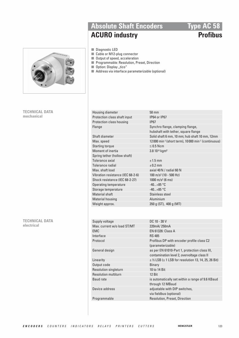
123E N C O D E R S C O U N T E R S I N D I C A T O R S R E L A Y S P R I N T E R S C U T T E R S
Absolute Shaft EncodersACURO industry
Type AC 58 Profibus
■ Diagnostic LED■ Cable or M12-plug connector■ Output of speed, acceleration■ Programmable: Resolution, Preset, Direction■ Option: Display „tico“■ Address via interface parameterizable (optional)
TECHNICAL DATAmechanical
Housing diameter 58 mm Protection class shaft input IP64 or IP67Protection class housing IP67Flange Synchro flange, clamping flange,
hubshaft with tether, square flange Shaft diameter Solid shaft 6 mm, 10 mm; hub shaft 10 mm, 12mmMax. speed 12 000 min-1 (short term), 10 000 min-1 (continuous)Starting torque ≤ 0.5 NcmMoment of inertia 3.8 10-6 kgm²Spring tether (hollow shaft)Tolerance axial ± 1.5 mmTolerance radial ± 0.2 mm Max. shaft load axial 40 N / radial 60 NVibration resistance (IEC 68-2-6) 100 m/s2 (10 - 500 Hz)Shock resistance (IEC 68-2-27) 1000 m/s2 (6 ms)Operating temperature -40...+85 °C Storage temperature -40...+85 °CMaterial shaft Stainless steelMaterial housing AluminiumWeight approx. 350 g (ST), 400 g (MT)
TECHNICAL DATAelectrical
Supply voltage DC 10 - 30 VMax. current w/o load ST/MT 220mA/ 250mAEMC EN 61326: Class AInterface RS 485Protocol Profibus DP with encoder profile class C2
(parameterizable)General design as per EN 61010-Part 1, protection class III,
contamination level 2, overvoltage class IILinearity ± ½ LSB (± 1 LSB for resolution 13, 14, 25, 26 Bit)Output code BinaryResolution singleturn 10 to 14 BitResolution multiturn 12 BitBaud rate is automatically set within a range of 9.6 KBaud
through 12 MBaud Device address adjustable with DIP switches,
via fieldbus (optional)Programmable Resolution, Preset, Direction
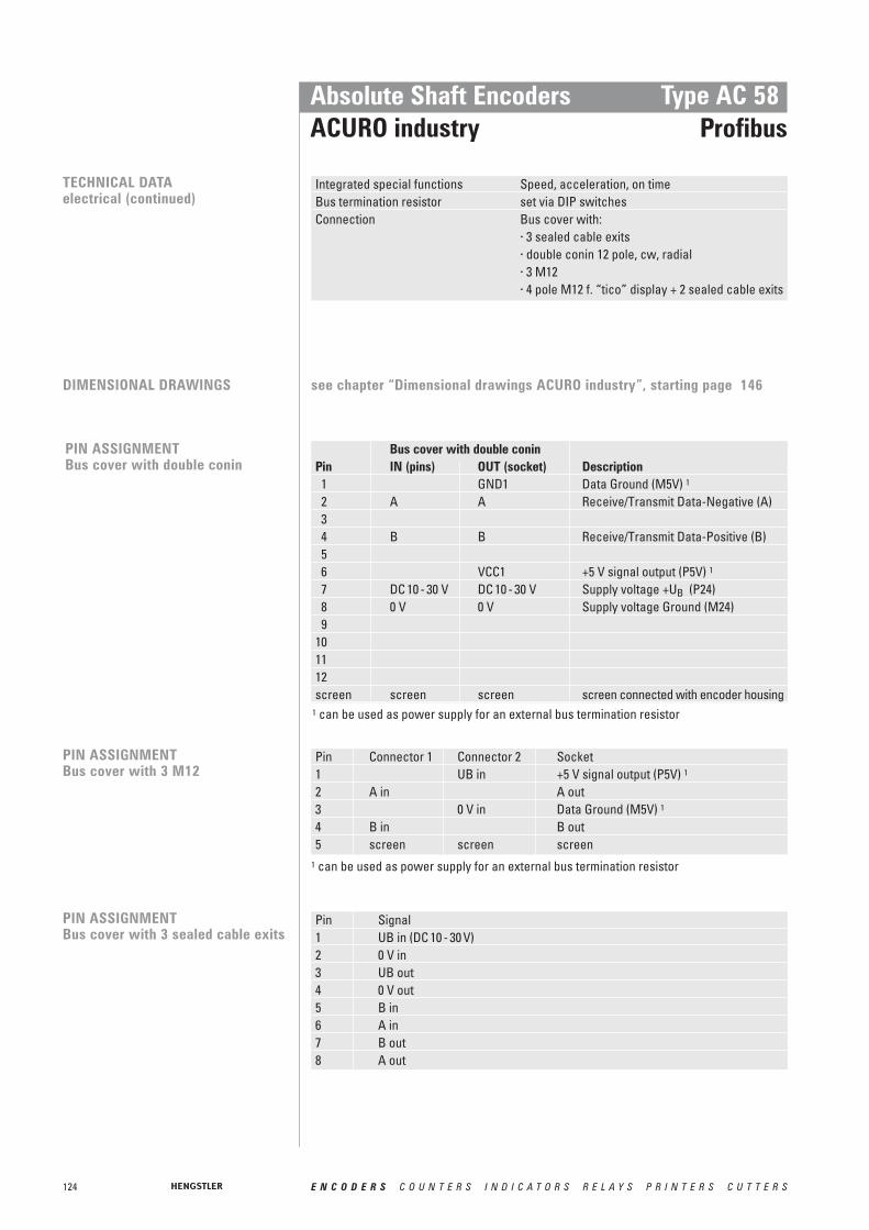
124 E N C O D E R S C O U N T E R S I N D I C A T O R S R E L A Y S P R I N T E R S C U T T E R S
Absolute Shaft Encoders ACURO industry
Type AC 58Profibus
PIN ASSIGNMENT Bus cover with double conin
Bus cover with double coninPin IN (pins) OUT (socket) Description1 GND1 Data Ground (M5V) 1
2 A A Receive/Transmit Data-Negative (A)34 B B Receive/Transmit Data-Positive (B)56 VCC1 +5 V signal output (P5V) 1
7 DC 10 - 30 V DC 10 - 30 V Supply voltage +UB (P24)8 0 V 0 V Supply voltage Ground (M24)9
101112screen screen screen screen connected with encoder housing
Pin Signal1 UB in (DC 10 - 30 V)2 0 V in3 UB out4 0 V out5 B in6 A in7 B out8 A out
PIN ASSIGNMENT Bus cover with 3 sealed cable exits
1 can be used as power supply for an external bus termination resistor
TECHNICAL DATAelectrical (continued)
Integrated special functions Speed, acceleration, on timeBus termination resistor set via DIP switchesConnection Bus cover with:
· 3 sealed cable exits· double conin 12 pole, cw, radial· 3 M12· 4 pole M12 f. “tico” display + 2 sealed cable exits
PIN ASSIGNMENT Bus cover with 3 M12
Pin Connector 1 Connector 2 Socket1 UB in +5 V signal output (P5V) 1
2 A in A out3 0 V in Data Ground (M5V) 1
4 B in B out5 screen screen screen
DIMENSIONAL DRAWINGS see chapter “Dimensional drawings ACURO industry”, starting page 146
1 can be used as power supply for an external bus termination resistor

125E N C O D E R S C O U N T E R S I N D I C A T O R S R E L A Y S P R I N T E R S C U T T E R S
Absolute Shaft EncodersACURO industry
Type AC 58Profibus
ACCESSORIES Ordering codeGSD-file www.hengstler.com
Technical manual, German 2 565 090 (Web)Technical manual, English 2 565 255 (Web)
Clamping eccentric for synchro flange 0 070 655Diaphragm coupling (hub 6/6 mm) 3 520 081Diaphragm coupling (hub 10/10 mm) 3 520 088
Mating connector for connection I (Bus input, 12 pole, bushing, cw) 3 539 202Mating connector for connection I (Bus output, 12 pole, pins, cw) 3 539 186
“Tico” display for connection T 0 731 205Connection cable bus cover (connection T) to “tico” display, 1.5m 3 539 575
STARTUPThe encoder can be easily andquickly installed and programmedwith the GSD file.

126 E N C O D E R S C O U N T E R S I N D I C A T O R S R E L A Y S P R I N T E R S C U T T E R S
Absolute Shaft EncodersACURO industry
Type AC 58 Profibus
ORDERING INFORMATION
Supplyvoltage Flange, Protection, ShaftResolution Interface ConnectionType
E DC 10 - 30 V S.41 Synchro, IP64, 6x10mm S.71 Synchro, IP67, 6x10mm K.42 Clamping, IP64, 10x19.5mm K.72 Clamping, IP67, 10x19.5mm K.46 Clamping, IP64, 9.52x19.5mmK.76 Clamping, IP67, 9.52x19.5mmF.42 Hubshaft with tether, IP64,
10x19.5mm hollow shaft F.47 Hubshaft with tether, IP64,
12x19.5mm hollow shaft F.46 Hubshaft with tether, IP64,
9.52x19.5mm hollow shaftQ.42 Square, IP64, 10x19.5mmQ.72 Square, IP67, 10x19.5mmQ.46 Square, IP64, 9.52x19.5mmQ.76 Square, IP67, 9.52x19.5mm
0010 10 Bit ST0012 12 Bit ST0013 13 Bit ST0014 14 Bit ST1212 12 Bit MT+12 Bit ST1213 12 Bit MT+13 Bit ST1214 12 Bit MT+14 Bit ST
AC58 DP Profibus I Bus cover with double conin 12 pole cw radial
R Bus cover with 3 M12T Bus cover with
4 pole M12 f. “tico”display + 2 sealedcable exits
Z Bus cover with 3 sealed cable exits
Preferably available versions are printed in bold type.

127E N C O D E R S C O U N T E R S I N D I C A T O R S R E L A Y S P R I N T E R S C U T T E R S
Absolute Shaft EncodersACURO industry
Type AC 58CANopen
■ Diagnostic LED■ Programmable: Resolution, Preset, Offset, Direction■ Output of speed and acceleration■ Operation timer■ Alarm and warning display■ Direction■ Option: display „tico“■ Address and baud rate via interface parameterizable
(optional)
TECHNICAL DATAmechanical
Housing diameter 58 mm Protection class shaft input IP64 or IP67Protection class housing Connection bus cover IP67
Connection cable, conin IP64 (IP67 optional)Flange Synchro flange, clamping flange,
hubshaft with tether, square flange Shaft diameter Solid shaft 6 mm, 10 mm; hub shaft 10 mm, 12mmMax. speed 12 000 min-1 (short term), 10 000 min-1 (continuous)Starting torque ≤ 0.5 NcmMoment of inertia 3.8 10-6 kgm²Spring tether (hollow shaft)Tolerance axial ± 1.5 mmTolerance radial ± 0.2 mm Max. shaft load axial 40 N / radial 60 NVibration resistance (IEC 68-2-6) 100 m/s2 (10 - 500 Hz)Shock resistance (IEC 68-2-27) 1000 m/s2 (6 ms)Operating temperature -40...+85 °C Storage temperature -40...+85 °CMaterial shaft Stainless steelMaterial housing AluminiumWeight approx. 350 g (ST), 400 g (MT)
TECHNICAL DATAelectrical
Supply voltage DC 10 - 30 VMax. current w/o load ST/MT 220 mA/ 250 mAEMC Noise emission according to EN 50081-2
Immunity to interference according to EN 50082-2Interface CAN High-Speed according to ISO/DIS 11898Protocol CANopen according to DS 301 with profile DSP 406,
programmable encoder according class C2General design as per EN 61010-Part 1, protection class III,
contamination level 2, overvoltage class IIProgrammable Resolution, Preset, Offset, DirectionResolution singleturn 10 to 14 BitResolution multiturn 12 BitLinearity ± ½ LSB (± 1 LSB for resolution 13, 14, 25, 26 Bit)Output code BinaryIntegrated special functions Speed, acceleration, round axis, limit values,
operation timer

128 E N C O D E R S C O U N T E R S I N D I C A T O R S R E L A Y S P R I N T E R S C U T T E R S
Conin Pin TPE cable Signal7 yellow CAN in+2 green CAN in -4 pink CAN out +5 grey CAN out -3 blue CAN GND in11 brown CAN GND out12 white 0.5 mm UB in10 brown 0.5 mm 0 V inscreen screen
PIN ASSIGNMENTBus cover with double conin
Bus cover withConin-PIN Pin insert (IN) Socket insert (OUT)1 CAN in + CAN out +2 CAN in - CAN out- 3 CAN GND in CAN GND out4 N.C. N.C.5 N.C. N.C.6 N.C. N.C.7 UB in UB out8 0 V in 0 V out9 N.C. N.C.screen screen 1 screen 1
Absolute Shaft EncodersACURO industry
Type AC 58 CANopen
1 screen connected with encoder housing
TECHNICAL DATAelectrical (continued)
Updating of values every millisecond (adjustable), on requestBasic identifier set via DIP switchesBaud rate set via DIP switches
within a range of 10 through 1000 Kbit/sBus termination resistor set via DIP switchesConnection Cable radial or axial
Conin radial or axial, cw or ccwBus cover with:· 3 sealed cable exits· double conin 9 pole cw radial· 4 pole M12 f. “tico” display + 2 sealed cable exits
DIMENSIONAL DRAWINGS see chapter “Dimensional drawings ACURO industry”, starting page 146
PIN ASSIGNMENTwith conin or cable
PIN ASSIGNMENTBus cover with 3 sealed cable exits
Connecting block KL 1 (10 pole)No. Signal name1 UB in (DC 10-30V)2 0 V in3 CAN in - (dominant L)4 CAN in + (dominant H)5 CAN GND in6 CAN GND out7 CAN out + (dominant H)8 CAN out - (dominant L)9 0 V out10 UB out (DC 10-30V)
Cable pairs
Pair 1
Pair 2
Pair 3
screen
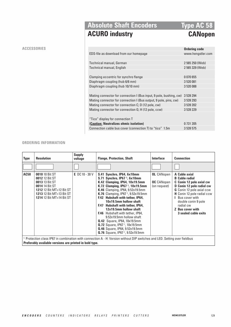
129E N C O D E R S C O U N T E R S I N D I C A T O R S R E L A Y S P R I N T E R S C U T T E R S
Absolute Shaft EncodersACURO industry
Type AC 58CANopen
ACCESSORIES Ordering codeEDS-file as download from our homepage www.hengstler.com
Technical manual, German 2 565 250 (Web)Technical manual, English 2 565 329 (Web)
Clamping eccentric for synchro flange 0 070 655Diaphragm coupling (hub 6/6 mm) 3 520 081Diaphragm coupling (hub 10/10 mm) 3 520 088
Mating connector for connection I (Bus input, 9 pole, bushing, cw) 3 539 294Mating connector for connection I (Bus output, 9 pole, pins, cw) 3 539 293Mating connector for connection C; D (12 pole, cw) 3 539 202Mating connector for connection G; H (12 pole, ccw) 3 539 229
“Tico” display for connection T(Caution: Neutralizes ohmic isolation) 0 731 205Connection cable bus cover (connection T) to “tico” 1.5m 3 539 575
ORDERING INFORMATION
Supplyvoltage Flange, Protection, ShaftResolution Interface ConnectionType
E DC 10 - 30 V S.41 Synchro, IP64, 6x10mm S.71 Synchro, IP67 1, 6x10mmK.42 Clamping, IP64, 10x19.5mmK.72 Clamping, IP67 1, 10x19.5mmK.46 Clamping, IP64, 9.52x19.5mmK.76 Clamping, IP67 1, 9.52x19.5mmF.42 Hubshaft with tether, IP64,
10x19.5mm hollow shaft F.47 Hubshaft with tether, IP64,
12x19.5mm hollow shaft F.46 Hubshaft with tether, IP64,
9.52x19.5mm hollow shaftQ.42 Square, IP64, 10x19.5mmQ.72 Square, IP67 1, 10x19.5mmQ.46 Square, IP64, 9.52x19.5mmQ.76 Square, IP67 1, 9.52x19.5mm
0010 10 Bit ST0012 12 Bit ST0013 13 Bit ST0014 14 Bit ST1212 12 Bit MT+12 Bit ST1213 12 Bit MT+13 Bit ST1214 12 Bit MT+14 Bit ST
AC58 OL CANopen
OC CANopen(on request)
A Cable axialB Cable radial C Conin 12 pole axial cwD Conin 12 pole radial cwG Conin 12 pole axial ccwH Conin 12 pole radial ccwI Bus cover with
double conin 9 poleradial cw
Z Bus cover with3 sealed cable exits
1 Protection class IP67 in combination with connection A - H: Version without DIP switches and LED. Setting over fieldbusPreferably available versions are printed in bold type.

130 E N C O D E R S C O U N T E R S I N D I C A T O R S R E L A Y S P R I N T E R S C U T T E R S
Absolute Shaft EncodersACURO industry
Type AC 58CANLayer2
■ Diagnostic LED■ Poll and auto mode■ Programmable: Direction, limit values■ Option: Display „tico“
TECHNICAL DATAmechanical
Housing diameter 58 mm Protection class shaft input IP64 or IP67Protection class housing Connection bus cover IP67
Connection conin, cable IP64 (IP67 optional)Flange Synchro flange, clamping flange,
hubshaft with tether, square flange Shaft diameter Solid shaft 6 mm, 10 mm; hub shaft 10 mm, 12mmMax. speed 12 000 min-1 (short term), 10 000 min-1 (continuous)Starting torque ≤ 0.5 NcmMoment of inertia 3.8 10-6 kgm²Spring tether (hollow shaft)Tolerance axial ± 1.5 mmTolerance radial ± 0.2 mm Max. shaft load axial 40 N / radial 60 NVibration resistance (IEC 68-2-6) 100 m/s2 (10 - 500 Hz)Shock resistance (IEC 68-2-27) 1000 m/s2 (6 ms)Operating temperature -40...+85 °C Storage temperature -40...+85 °CMaterial shaft Stainless steelMaterial housing AluminiumWeight approx. 350 g (ST), 400 g (MT)
TECHNICAL DATAelectrical
Supply voltage DC 10 - 30 V (SELV)Max. current w/o load ST/MT 220 mA/ 250 mAEMC Noise emission according to EN 50081-2
Immunity to interference according to EN 50082-2Interface CAN High-Speed according to ISO/DIS 11898Protocol CAN 2.0 AGeneral design as per EN 61010-Part 1, protection class III,
contamination level 2, overvoltage class IIResolution singleturn 10 to 14 BitResolution multiturn 12 BitProgrammable Direction, limit valuesLinearity ± ½ LSB (± 1 LSB for resolution 13, 14, 25, 26 Bit)Output code BinaryUpdating of values every millisecondBasic identifier set via DIP switchesBaud rate set via DIP switches
within a range of 10 through 1000 Kbit/sBus termination resistor set via DIP switches
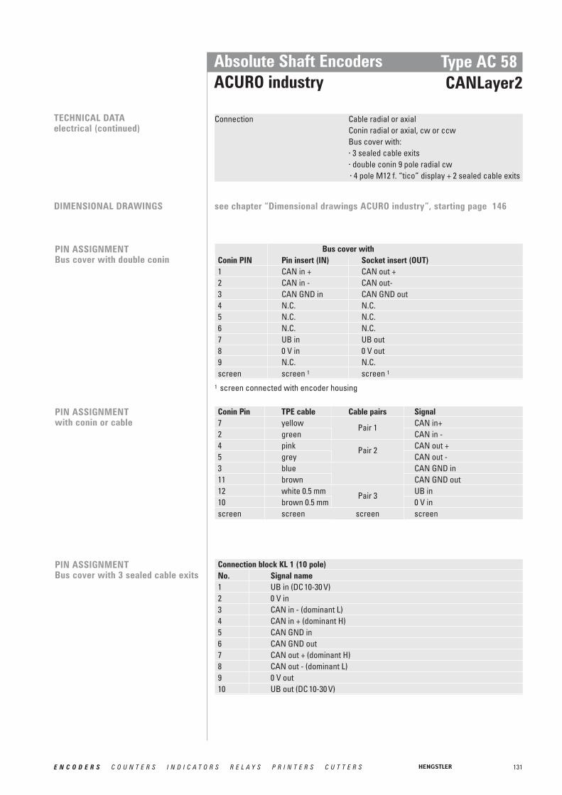
131E N C O D E R S C O U N T E R S I N D I C A T O R S R E L A Y S P R I N T E R S C U T T E R S
Conin Pin TPE cable Signal7 yellow CAN in+2 green CAN in -4 pink CAN out +5 grey CAN out -3 blue CAN GND in11 brown CAN GND out12 white 0.5 mm UB in10 brown 0.5 mm 0 V inscreen screen screen
PIN ASSIGNMENTBus cover with double conin
Bus cover withConin PIN Pin insert (IN) Socket insert (OUT)1 CAN in + CAN out +2 CAN in - CAN out- 3 CAN GND in CAN GND out4 N.C. N.C.5 N.C. N.C.6 N.C. N.C.7 UB in UB out8 0 V in 0 V out9 N.C. N.C.screen screen 1 screen 1
Absolute Shaft EncodersACURO industry
Type AC 58 CANLayer2
1 screen connected with encoder housing
TECHNICAL DATAelectrical (continued)
Connection Cable radial or axialConin radial or axial, cw or ccwBus cover with: · 3 sealed cable exits· double conin 9 pole radial cw· 4 pole M12 f. “tico” display + 2 sealed cable exits
DIMENSIONAL DRAWINGS see chapter “Dimensional drawings ACURO industry”, starting page 146
PIN ASSIGNMENTwith conin or cable
PIN ASSIGNMENTBus cover with 3 sealed cable exits
Connection block KL 1 (10 pole)No. Signal name1 UB in (DC 10-30 V)2 0 V in3 CAN in - (dominant L)4 CAN in + (dominant H)5 CAN GND in6 CAN GND out7 CAN out + (dominant H)8 CAN out - (dominant L)9 0 V out10 UB out (DC 10-30 V)
Cable pairs
Pair 1
Pair 2
Pair 3
screen
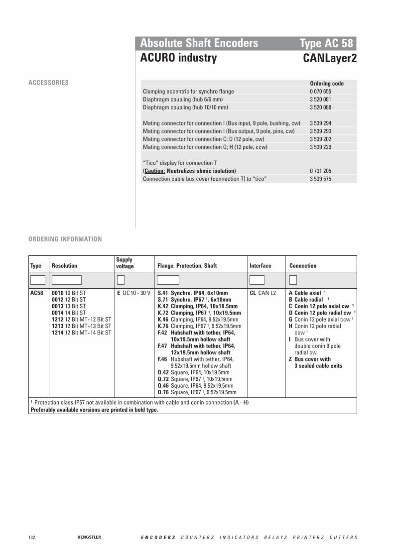
132 E N C O D E R S C O U N T E R S I N D I C A T O R S R E L A Y S P R I N T E R S C U T T E R S
Absolute Shaft EncodersACURO industry
Type AC 58CANLayer2
ACCESSORIES Ordering codeClamping eccentric for synchro flange 0 070 655Diaphragm coupling (hub 6/6 mm) 3 520 081Diaphragm coupling (hub 10/10 mm) 3 520 088
Mating connector for connection I (Bus input, 9 pole, bushing, cw) 3 539 294Mating connector for connection I (Bus output, 9 pole, pins, cw) 3 539 293Mating connector for connection C; D (12 pole, cw) 3 539 202Mating connector for connection G; H (12 pole, ccw) 3 539 229
“Tico” display for connection T(Caution: Neutralizes ohmic isolation) 0 731 205Connection cable bus cover (connection T) to “tico” 3 539 575
ORDERING INFORMATION
Supplyvoltage Flange, Protection, ShaftResolution Interface ConnectionType
E DC 10 - 30 V S.41 Synchro, IP64, 6x10mm S.71 Synchro, IP67 1, 6x10mmK.42 Clamping, IP64, 10x19.5mmK.72 Clamping, IP67 1, 10x19.5mmK.46 Clamping, IP64, 9.52x19.5mmK.76 Clamping, IP67 1, 9.52x19.5mmF.42 Hubshaft with tether, IP64,
10x19.5mm hollow shaft F.47 Hubshaft with tether, IP64,
12x19.5mm hollow shaftF.46 Hubshaft with tether, IP64,
9.52x19.5mm hollow shaftQ.42 Square, IP64, 10x19.5mmQ.72 Square, IP67 1, 10x19.5mmQ.46 Square, IP64, 9.52x19.5mmQ.76 Square, IP67 1, 9.52x19.5mm
0010 10 Bit ST0012 12 Bit ST0013 13 Bit ST0014 14 Bit ST1212 12 Bit MT+12 Bit ST1213 12 Bit MT+13 Bit ST1214 12 Bit MT+14 Bit ST
AC58 CL CAN L2 A Cable axial 1B Cable radial 1C Conin 12 pole axial cw 1D Conin 12 pole radial cw 1G Conin 12 pole axial ccw 1H Conin 12 pole radial
ccw 1I Bus cover with
double conin 9 pole radial cw
Z Bus cover with3 sealed cable exits
1 Protection class IP67 not available in combination with cable and conin connection (A - H)Preferably available versions are printed in bold type.
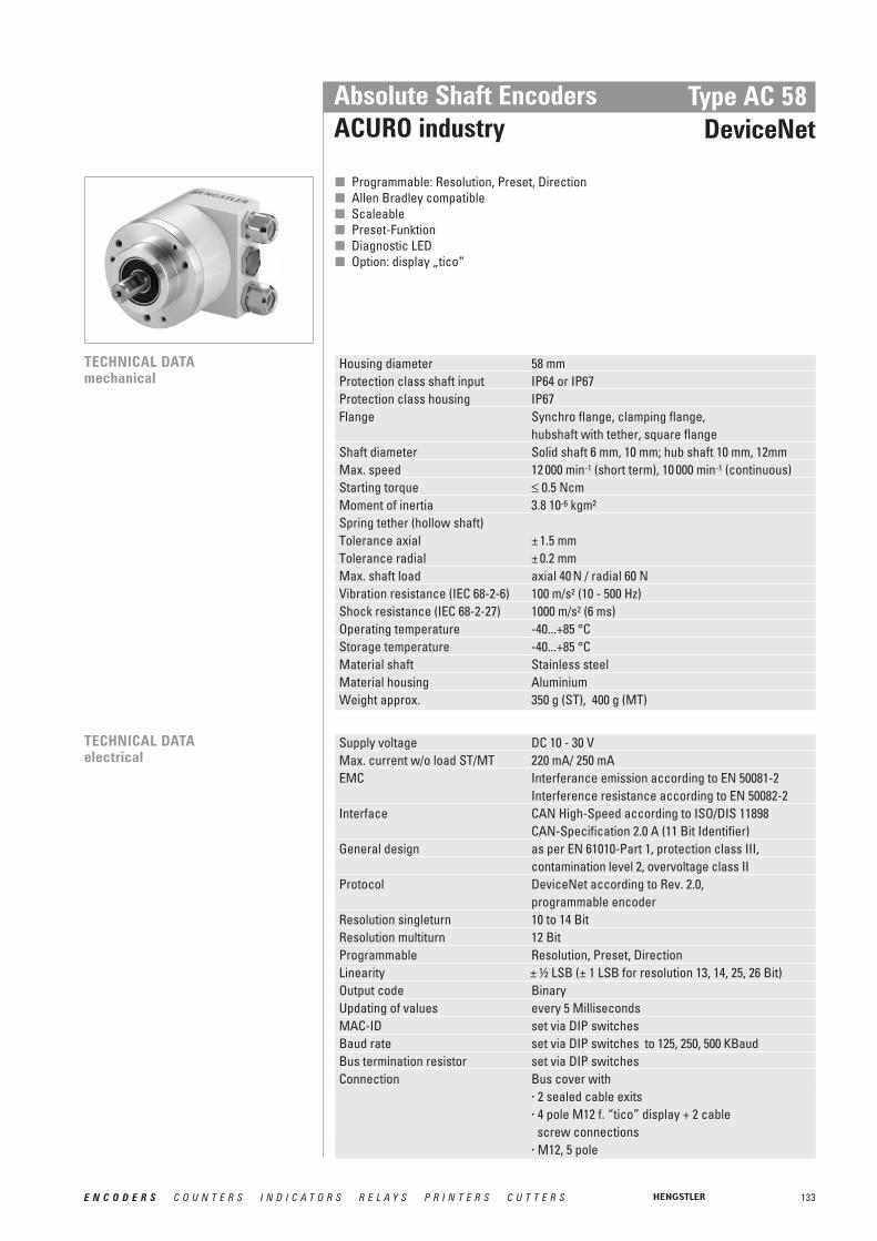
133E N C O D E R S C O U N T E R S I N D I C A T O R S R E L A Y S P R I N T E R S C U T T E R S
Absolute Shaft EncodersACURO industry
Type AC 58DeviceNet
■ Programmable: Resolution, Preset, Direction■ Allen Bradley compatible■ Scaleable■ Preset-Funktion■ Diagnostic LED■ Option: display „tico“
TECHNICAL DATAmechanical
Housing diameter 58 mm Protection class shaft input IP64 or IP67Protection class housing IP67Flange Synchro flange, clamping flange,
hubshaft with tether, square flange Shaft diameter Solid shaft 6 mm, 10 mm; hub shaft 10 mm, 12mm Max. speed 12 000 min-1 (short term), 10 000 min-1 (continuous)Starting torque ≤ 0.5 NcmMoment of inertia 3.8 10-6 kgm²Spring tether (hollow shaft)Tolerance axial ± 1.5 mmTolerance radial ± 0.2 mmMax. shaft load axial 40 N / radial 60 NVibration resistance (IEC 68-2-6) 100 m/s2 (10 - 500 Hz)Shock resistance (IEC 68-2-27) 1000 m/s2 (6 ms)Operating temperature -40...+85 °C Storage temperature -40...+85 °CMaterial shaft Stainless steelMaterial housing AluminiumWeight approx. 350 g (ST), 400 g (MT)
TECHNICAL DATAelectrical
Supply voltage DC 10 - 30 V Max. current w/o load ST/MT 220 mA/ 250 mAEMC Interferance emission according to EN 50081-2
Interference resistance according to EN 50082-2 Interface CAN High-Speed according to ISO/DIS 11898
CAN-Specification 2.0 A (11 Bit Identifier)General design as per EN 61010-Part 1, protection class III,
contamination level 2, overvoltage class IIProtocol DeviceNet according to Rev. 2.0,
programmable encoderResolution singleturn 10 to 14 BitResolution multiturn 12 BitProgrammable Resolution, Preset, DirectionLinearity ± ½ LSB (± 1 LSB for resolution 13, 14, 25, 26 Bit)Output code BinaryUpdating of values every 5 MillisecondsMAC-ID set via DIP switchesBaud rate set via DIP switches to 125, 250, 500 KBaudBus termination resistor set via DIP switchesConnection Bus cover with
· 2 sealed cable exits· 4 pole M12 f. “tico” display + 2 cable
screw connections· M12, 5 pole

134 E N C O D E R S C O U N T E R S I N D I C A T O R S R E L A Y S P R I N T E R S C U T T E R S
STARTUPThe encoder can be easily andquickly installed and programmedwith the EDS file.
PIN ASSIGNMENTBus cover with 2 sealed cable exits
TerminalsNo. Signal name1 UB in (DC 10 - 30V)2 0 V in3 CAN-L4 CAN-H5 DRAIN6 DRAIN7 CAN-H8 CAN-L9 0 V out10 UB out (DC 10 - 30V)
Absolute Shaft EncodersACURO industry
Type AC 58 DeviceNet
RECOMMENDEDDATA TRANSTERLead type A
Shaft resistance 135...165 Ω (3...20MHz)Operating capacity < 30pF/mLoop impedance < 110 Ω/kmStrand diameter > 0.64 mmStrand cross section > 0.34 mm2
TRANSFER SPEEDS Segment length kBit/s500 m 125250 m 250100 m 500
DIMENSIONAL DRAWINGS see chapter “Dimensional drawings ACURO industry”, starting page 146

135E N C O D E R S C O U N T E R S I N D I C A T O R S R E L A Y S P R I N T E R S C U T T E R S
Absolute Shaft EncodersACURO industry
Type AC 58 DeviceNet
Ordering codeEDS-file as download from our homepage www.hengstler.com
Technical manual, German 2 565 094 (Web)Technical manual, English 2 565 256 (Web)
Clamping eccentric for synchro flange 0 070 655Diaphragm coupling (hub 6/6 mm) 3 520 081Diaphragm coupling (hub 10/10 mm) 3 520 088
“Tico” display for connection T 0 731 205Connection cable bus cover (connection T) to “tico” 3 539 575
ACCESSORIES
PIN ASSIGNMENTBus cover with M12, 5 pole
Pin Connector Colour1 UB in (DC 10 - 30V) white2 0 V in blue3 CAN-L green/yellow 4 CAN-H black5 DRAIN brown
ORDERING INFORMATION
Supplyvoltage Flange, Protection, ShaftResolution Interface ConnectionType
E DC 10 - 30 V S.41 Synchro, IP64, 6x10mm S.71 Synchro, IP67, 6x10mmK.42 Clamping, IP64, 10x19.5mmK.72 Clamping, IP67, 10x19.5mmK.46 Clamping, IP64, 9.52x19.5mmK.76 Clamping, IP67, 9.52x19.5mmF.42 Hubshaft with tether, IP64,
10x19.5mm hollow shaftF.47 Hubshaft with tether, IP64,
12x19.5mm hollow shaftF.46 Hubshaft with tether, IP64,
9.52x19.5mm hollow shaftQ.42 Square, IP64, 10x19.5mmQ.72 Square, IP67, 10x19.5mmQ.46 Square, IP64, 9.52x19.5mmQ.76 Square, IP67, 9.52x19.5mm
0010 10 Bit ST0012 12 Bit ST0013 13 Bit ST0014 14 Bit ST1212 12 Bit MT+12 Bit ST1213 12 Bit MT+13 Bit ST1214 12 Bit MT+14 Bit ST
AC58 VD DeviceNet S Bus cover with M12,5 pole radial
T Bus cover with 4 pole M12 for “tico” display+ 2 sealed cable exits
Z Bus cover with 2 sealed cable exits
Preferably available versions are printed in bold type.

136 E N C O D E R S C O U N T E R S I N D I C A T O R S R E L A Y S P R I N T E R S C U T T E R S
Absolute Shaft EncodersACURO industry
Type AC 58Interbus
■ Resolution programmable (K3)■ Resolution up to 24 Bit■ Preset (K3)■ Direction (K3)■ Option: display „tico“■ Diagnostic LED
TECHNICAL DATAmechanical
Housing diameter 58 mm Protection class shaft input IP64 or IP67Protection class housing Connection bus cover IP67
Connection cable IP64 (IP67 optional)Flange Synchro flange, clamping flange,
hubshaft with tether, square flange Shaft diameter Solid shaft 6 mm, 10 mm; hub shaft 10 mm, 12mmMax. speed 12 000 min-1 (short term), 10 000 min-1 (continuous)Starting torque ≤ 0.5 NcmMoment of inertia 3.8 10-6 kgm²Spring tether (hollow shaft)Tolerance axial ± 1.5 mmTolerance radial ± 0.2 mm Max. shaft load axial 40 N / radial 60 NVibration resistance (IEC 68-2-6) 100 m/s2 (10 - 500 Hz)Shock resistance (IEC 68-2-27) 1000 m/s2 (6 ms)Operating temperature -40...+70 °C Storage temperature -40...+85 °CMaterial shaft Stainless steelMaterial housing AluminiumWeight approx. 350 g (ST), 400 g (MT)
TECHNICAL DATAelectrical
Supply voltage DC 10 - 30 V Max. current w/o load; 220 mA/250 mA;recommended external fuse T 0.25 Acurrent with looped through max. 4.5 A for bus cover with double conin,voltage supply; max. 2 A for all other connections;recommended external fuse T 4.5 A bus cover with with double conin,
T 2 A for all other connectionsEMC Interference emission according to EN 50081-2
Interference resistance according to EN 50082-2 Interface Remote installation busProtocol Interbus with ENCOM Profile K3
(parameterizable), K2General design as per EN 61010-Part 1, protection class III,
contamination level 2, overvoltage class IILinearity ± ½ LSB Output code 32 Bit BinaryBaud rate 500 KBaudUpdating of values every 600 μs
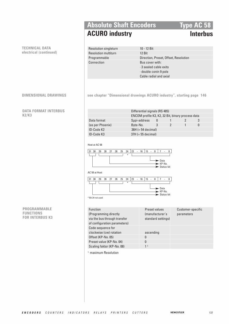
Host at AC 58
31 30 29 28 27 26 25 24 23 - 16 15 - 8 7 - 0*
DataKP-No.Status-bit
AC 58 at Host
31 30 29 28 27 26 25 24 23 - 16 15 - 8 7 - 0*
DataKP-No.Status-bit
* Bit 24 not used
137E N C O D E R S C O U N T E R S I N D I C A T O R S R E L A Y S P R I N T E R S C U T T E R S
Absolute Shaft EncodersACURO industry
Type AC 58Interbus
TECHNICAL DATAelectrical (continued)
Resolution singleturn 10 - 12 BitResolution multiturn 12 BitProgrammable Direction, Preset, Offset, ResolutionConnection Bus cover with:
· 3 sealed cable exits· double conin 9 poleCable radial and axial
Differential signals (RS 485)ENCOM profile K3, K2, 32 Bit, binary process data
Data format Sμpi-address 0 1 2 3(as per Phoenix) Byte-No. 3 2 1 0ID-Code K2 36H (= 54 decimal)ID-Code K3 37H (= 55 decimal)
DATA FORMAT INTERBUS K2/K3
Function Preset values Customer-specific(Programming directly (manufacturer´s parametersvia the bus through transfer standard settings)of configuration parameters)Code sequence forclockwise (cw) rotation ascendingOffset (KP-No. 05) 0Preset value (KP-No. 04) 0Scaling faktor (KP-No. 08) 1 1
PROGRAMMABLEFUNCTIONSFOR INTERBUS K3
1 maximum Resolution
DIMENSIONAL DRAWINGS see chapter “Dimensional drawings ACURO industry”, starting page 146

138 E N C O D E R S C O U N T E R S I N D I C A T O R S R E L A Y S P R I N T E R S C U T T E R S
PIN ASSIGNMENTCable with Conin 12 pole(Standard according to ENCOM for remote installation bus)
Plug pin Signal1 D0223 DI 245 D0167 DI 18910 0 V (supply voltage)11 GND- signal output 1
12 DC 10 - 30 V
RBSTDI1
D01
DI2
D02
1 Due to electrical isolation not identical with 0 V (supply voltage) identisch;used by T-manifold to set the RBST input logical on „0“
Absolute Shaft EncodersACURO industry
Type AC 58Interbus
PIN ASSIGNMENTBus cover with double conin(Standard according to ENCOM for remote installation bus)
Pin IN (9 pole pins) OUT (9 pole socket)1 D01 D0223 DI 1 DI 245 GND- signal output 1 GND- signal output 1
6 PE 2 PE 2
7 DC 10 - 30 V (SELV) DC 10 - 30 V (SELV)8 0 V (supply voltage) 0 V (supply voltage)9 N.C. RBST
DI2DI1
D02D01
1 Due to electrical isolation not identical with 0 V (supply voltage) identisch;used by T-manifold to set the RBST input logical on „0“
2 Functional earthing; connected with the encoder housing
PIN ASSIGNMENTBus cover with 3 sealed cable exits
Connection clamp (12 pole)1 UB +2 GND3 DI1+4 DI1-5 D01+6 D01-7 D02+8 D02-9 DI2+10 DI2-11 RBST12 GND-

139E N C O D E R S C O U N T E R S I N D I C A T O R S R E L A Y S P R I N T E R S C U T T E R S
Ordering codeTechnical manual, German 2 565 217
www.hengstler.com
Clamping eccentric for synchro flange 0 070 655Diaphragm coupling (hub 6/6 mm) 3 520 081Diaphragm coupling (hub 10/10 mm) 3 520 088
Mating connector for connection I 3 539 294(Bus input, 9 pole, bushing, cw)Mating connector for connection I 3 539 293(Bus output, 9 pole, pins, cw)
ACCESSORIES
Absolute Shaft EncodersACURO industry
Type AC 58 Interbus
ORDERING INFORMATION
Supplyvoltage Flange, Protection, ShaftResolution Interface ConnectionType
E DC 10 - 30 V S.41 Synchro, IP64, 6x10mm S.71 Synchro, IP67 1, 6x10mmK.42 Clamping, IP64, 10x19.5mmK.72 Clamping, IP67 1, 10x19.5mmK.46 Clamping, IP64, 9.52x19.5mmK.76 Clamping, IP67 1, 9.52x19.5mmF.42 Hubshaft with tether, IP64,
10x19.5mm hollow shaft F.47 Hubshaft with tether, IP64,
12x19.5mm hollow shaftF.46 Hubshaft with tether, IP64,
9.52x19.5mm hollow shaftQ.42 Square, IP64, 10x19.5mmQ.72 Square, IP67 1, 10x19.5mmQ.46 Square, IP64, 9.52x19.5mmQ.76 Square, IP67 1, 9.52x19.5mm
0010 10 Bit ST0012 12 Bit ST1212 12 Bit ST+12 Bit MT
AC58 I3 Interbus K3I2 Interbus K2
A-B5-C Cable axial with conin connector at the 1.5m cable
B-B5-C Cable radial with conin connector at the 1.5m cable
I Bus cover with double conin
Z Bus cover with 3 sealed cable exits
1 Protection class IP67 not available in combination with LED display for connection with cablePreferably available versions are printed in bold type.

140 E N C O D E R S C O U N T E R S I N D I C A T O R S R E L A Y S P R I N T E R S C U T T E R S
Absolute Shaft EncodersACURO industry
Type AC 58SUCOnet
■ Compact design■ SUCOnet or Hengstler-G1-Protocol■ Parameterizable: preset, direction,
scaling factor, resolution■ PC communication via RS 485 with
Hengstler-G1-Protocol
TECHNICAL DATAmechanical
Housing diameter 58mmShaft one sided open hub shaft, VollwelleFlange Synchro flange, clamping flange,
hubshaft with tether, square flange Shaft diameter Solid shaft 6 mm, 10 mm; hub shaft 10 mm, 12mmProtection class shaft input IP64 or IP67Protection class housing IP64Max. shaft load axial/ radial 40/ 60 NStarting torque ≤ 0,5 NcmMax. speed 12 000 min-1 (short term)
10 000 min-1 (continuous)Operating temperature -10...+60 °C Storage temperature -25...+85 °CShock resistance 1 000 m/ s²Vibration resistance 100 m/ s²Material shaft Stainless steelMaterial housing AluminiumWeight ST/MT 260g/ 310g
TECHNICAL DATAelectrical
Supply voltage DC 10 - 30 V Max. current w/o load 200 mAEMC Interference emission according to EN 50081-2
Interference resistance according to EN 50082-2 Interface RS485Protocol SUCOnet or Hengstler-G1-ProtocolResolution singleturn 10 - 13 BitResolution multiturn 12 BitOutput code BinaryLinearity ± ½ LSB (± 1 LSB for resolution 13 and 25 Bit)Device address set via DIP switchesBus termination resistor set via DIP switchesProgrammable (SUCOnet) Direction, ResolutionConnection Cable radial or axial
AC 58 with hub shaft AC 58 with solid shaft
DIMENSIONAL DRAWINGS see chapter “Dimensional drawings ACURO industry”, starting page 146
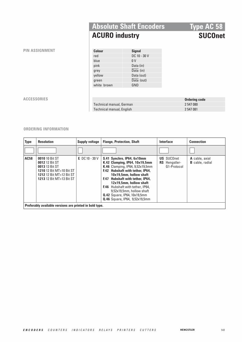
141E N C O D E R S C O U N T E R S I N D I C A T O R S R E L A Y S P R I N T E R S C U T T E R S
Absolute Shaft EncodersACURO industry
Type AC 58SUCOnet
PIN ASSIGNMENT
Ordering codeTechnical manual, German 2 547 080Technical manual, English 2 547 081
Colour Signalred DC 10 - 30 Vblue 0 Vpink Data (in)grey (in)yellow Data (out)green (out)white brown GND
Data
Data
ACCESSORIES
ORDERING INFORMATION
Supply voltage Flange, Protection, ShaftResolution Interface ConnectionType
E DC 10 - 30 V S.41 Synchro, IP64, 6x10mm K.42 Clamping, IP64, 10x19,5mmK.46 Clamping, IP64, 9,52x19,5mmF.42 Hubshaft with tether, IP64,
10x19,5mm, hollow shaft F.47 Hubshaft with tether, IP64,
12x19,5mm, hollow shaft F.46 Hubshaft with tether, IP64,
9,52x19,5mm, hollow shaftQ.42 Square, IP64, 10x19,5mmQ.46 Square, IP64, 9,52x19,5mm
0010 10 Bit ST0012 12 Bit ST0013 13 Bit ST1210 12 Bit MT+10 Bit ST1212 12 Bit MT+12 Bit ST1213 12 Bit MT+13 Bit ST
AC58 US SUCOnetRS Hengstler-
G1-Protocol
A cable, axialB cable, radial
Preferably available versions are printed in bold type.

142 E N C O D E R S C O U N T E R S I N D I C A T O R S R E L A Y S P R I N T E R S C U T T E R S
Absolute Shaft EncodersACURO industry
Type AC 58SSI programmable
■ Compact design: 59 mm length for single or multiturn■ Aids for start up and operation:
diagnostic LED, preset key with optical response, status information■ Parameterization: Resolution, code type, direction, output format, warning, alarm■ Parameters can be stored in a non-volatile memory■ Integrated RS232 interface
TECHNICAL DATAmechanical
Housing diameter 58 mm Protection class shaft input IP64 or IP67Protection class housing IP64 (IP67 optional)Flange Synchro flange, clamping flange,
hubshaft with tether, square flange Shaft diameter Solid shaft 6 mm, 10 mm; hub shaft 10 mm, 12mmMax. speed 12 000 min-1 (short term), 10 000 min-1 (continuous)Starting torque ≤ 0.5 NcmMoment of inertia 3.8 10-6 kgm²Spring tether (hollow shaft)Tolerance axial ±1.5 mmTolerance radial ±0.2 mmMax. shaft load axial 40 N / radial 60 NVibration resistance (IEC 68-2-6) 100 m/s2 (10 - 500 Hz)Shock resistance (IEC 68-2-27) 1 000 m/s2 (6 ms)Operating temperature -40...+70 °C Storage temperature -40...+85 °CMaterial shaft Stainless steelMaterial housing AluminiumWeight approx. ST/MT 260g/ 310g
TECHNICAL DATAelectrical
Supply voltage DC 10 - 30 V Max. current w/o load ST/MT max. 250 mAInterface SSI programmableLines / drivers Clock and Data / RS422Output code Binary or GrayResolution singleturn 10 - 17 BitResolution multiturn 12 BitParameterization Resolution, code type, direction,
output format, warning, alarmControl input Direction, Preset 1, Preset 2Alarm output Alarm bitStatus LED Green = ok; red = alarmConnection Cable radial or axial
Conin radial or axial

143E N C O D E R S C O U N T E R S I N D I C A T O R S R E L A Y S P R I N T E R S C U T T E R S
OUTPUT FORMATS SSI
MSB-orientedMultiturn
A clock brush is applied at the SSI inter-face, causing the encoder data to be seri-ally clocked out. With each new clockbrush (min. interval 30 ms) new data is rea-dout.
The following main parameters are pro-grammable:•Preset: Software-Preset and via input/
pushbutton settable presets (can beinactivated)
•Offset:Relative shifting of actual encoder value.
•Scaling: The actual value of the encoder is multiplied with the factor < 1.Direct entry, increments per measuring distance or per revolution.
•Direction of rotation: Can be changed via software or input (can be inactivated)
•Output formats SSI: Tree format or standard format (MSB oriented)
•Output code: The choices are Gray or binary code, integer or two’s complement representation. Selection of significant bit between 16 and 24 Bit.
In addition, programming of max. 7 statusbits is possible:•up to 4 warning positions•overspeed•encoder standstill•parity•encoder error•direction of rotation
SYNCHRONOUS-SERALTRANSFER (SSI)
PROGRAMMING WITH SSI To program the absolute encoder yourequire a PC, the software WinSSI and theadapter cable.
The encoder is connected to the powersupply and the serial interface of your PCwith the adapter cable.
Using the menue-assisted programme youcan then configure the encoder accordingto the parameters you require.
The max. data transfer rate depends on the cable length. For Clock / and Data / please use twisted pairs. Use shielded cable.DataClock
RECOMMENDED DATA TRANSFER RATEFOR SSI
Cable length Baud rate< 50 m < 400 kHz< 100 m < 300 kHz< 200 m < 200 kHz< 400 m < 100 kHz
Absolute Shaft Encoders ACURO industry
Type AC 58 SSI programmable
M1124 M10 M9 M8 M7 M6 M5 M4 M3 M2 M1 M0 S11 S10 S9 S8 S7 S6 S5 S4 S3 S2 S1 S0
1 2 3 4 5 6 7 8 9 10 11 12 13 14 15 16 17 18 19 20 21 22 23 24
M1023 M9 M8 M7 M6 M5 M4 M3 M2 M1 M0 S11 S10 S9 S8 S7 S6 S5 S4 S3 S2 S1 S0 0
0
0
0
0
0
0
0
0
0
0
0
0
0
0 0
0
0
0
0
0
0
0
0
0
0
0
0
0
0
0
0
0
0
0
0
0
0
0
0
0
0
0
0
0
0
0
0
0
0
0
0
0
0
0
0
0
0
0
0
0
0
0
0
0
0
0
0
0
0
0
0
0
0
0
0
0
0
0
0
0
0
0
0
0
0
0
0
0
0
0
0
0
0
0
0
0
0
0
0
0
0
0
0
0
0
0
0
0
0
0
0
0
0
0
0
0
0
0
0
M922 M8 M7 M6 M5 M4 M3 M2 M1 M0 S11 S10 S9 S8 S7 S6 S5 S4 S3 S2 S1 S0
M821 M7 M6 M5 M4 M3 M2 M1 M0 S11 S10 S9 S8 S7 S6 S5 S4 S3 S2 S1 S0
M720 M6 M5 M4 M3 M2 M1 M0 S11 S10 S9 S8 S7 S6 S5 S4 S3 S2 S1 S0
M619 M5 M4 M3 M2 M1 M0 S11 S10 S9 S8 S7 S6 S5 S4 S3 S2 S1 S0
M518 M4 M3 M2 M1 M0 S11 S10 S9 S8 S7 S6 S5 S4 S3 S2 S1 S0
M417 M3 M2 M1 M0 S11 S10 S9 S8 S7 S6 S5 S4 S3 S2 S1 S0
M316 M2 M1 M0 S11 S10 S9 S8 S7 S6 S5 S4 S3 S2 S1 S0
M215 M1 M0 S11 S10 S9 S8 S7 S6 S5 S4 S3 S2 S1 S0
M114 M0 S11 S10 S9 S8 S7 S6 S5 S4 S3 S2 S1 S0
M013 S11 S10 S9 S8 S7 S6 S5 S4 S3 S2 S1 S0
S1112 S10 S9 S8 S7 S6 S5 S4 S3 S2 S1 S0
S1011 S8 S7 S6 S5 S4 S3 S2 S1 S0
S910 S8 S7 S6 S5 S4 S3 S2 S1 S0
S89
S9
S7 S6 S5 S4 S3 S2 S1 S0
Num
ber o
f dat
a bi
ts
Clockpulse
...
Statusbits 7 ...1
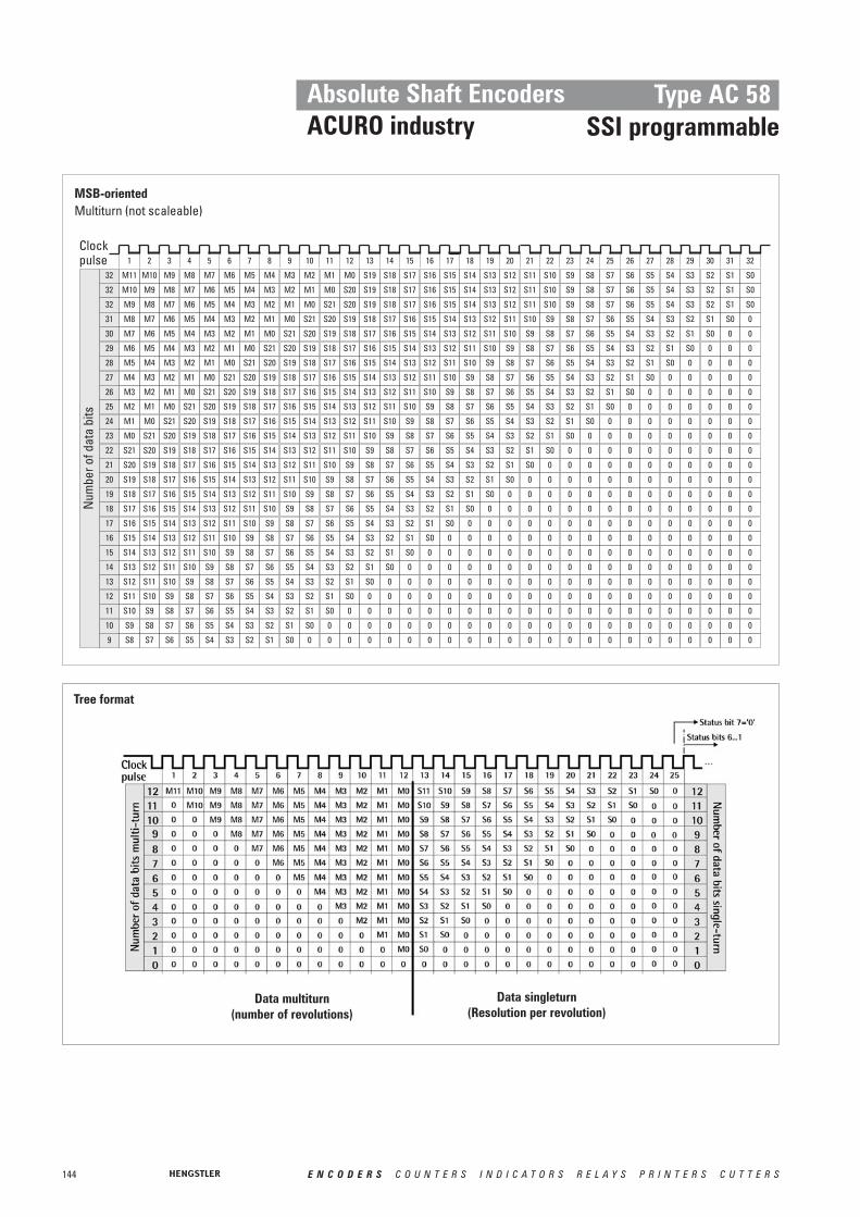
M6
144 E N C O D E R S C O U N T E R S I N D I C A T O R S R E L A Y S P R I N T E R S C U T T E R S
Tree format
Data singleturn(Resolution per revolution)
Data multiturn(number of revolutions)
Absolute Shaft EncodersACURO industry
Type AC 58SSI programmable
1 2 3 4 5 6 7 8 9 10 11 12 13 14 15 16 17 18 19 20 21 22 23 24 25 26 27 28 29 30 31 32
M1132 M10
M10
M9
M9
M9
M8
M8
M8
M8
M7
M7
M7
M7
M7
M6
M6
M6
M6
M6
M5
M5
M5
M5
M5
M5
M5
M4
M4
M4
M4
M4
M4
M4
M4
M3
M3
M3
M3
M3
M3
M3
M3
M3
M2
M2
M2
M2
M2
M2
M2
M2
M2
M2
M1
M1
M1
M1
M1
M1
M1
M1
M1
M1
M1
M0
M0
M0
M0
M0
M0
M0
M0
M0
M0
M0
M0
S19
S20
S20
S20
S20
S20
S20
S20
S20
S20
S20
S20
S20
S20
S21
S21
S21
S21
S21
S21
S21
S21
S21
S21
S21
S18
S18
S17
S17
S17
S16
S16
S16
S16
S15
S15
S15
S15
S15
S14
S14
S14
S14
S14
S14
S13
S13
S13
S13
S13
S13
S13
32
S12
S12
S12
S12
S12
S12
S12
S12
S11
S11
S11
S11
S11
S11
S11
S11
S11
S10
S10
S10
S10
S10
S10
S10
S10
S10
S10
S9
S9
S9
S9
S9
S9
S9
S9
S9
S9
S9
S8
S8
S8
S8
S8
S8
S8
S8
S8
S8
S8
S8
S7
S7
S7
S7
S7
S7
S7
S7
S7
S7
S7
S7
S6
S6
S6
S6
S6
S6
S6
S6
S6
S6
S6
S6
S5
S5
S5
S5
S5
S5
S5
S5
S5
S5
S5
S5
S4
S4
S4
S4
S4
S4
S4
S4
S4
S4
S4
S4
S3
S3
S3
S3
S3
S3
S3
S3
S3
S3
S3
S3
S2
S2
S2
S2
S2
S2
S2
S2
S2
S2
S2
S2
S1
S1
S1
S1
S1
S1
S1
S1
S1
S1
S1
S1
S0
S19
S19
S19
S19
S19
S19
S19
S19
S19
S19
S19
S19
S19
S19
S18 S17 S16 S15 S14 S13 S12 S11 S10 S9 S8 S7 S6 S5 S4 S3 S2 S1 S0
S18 S17 S16 S15 S14 S13 S12 S11 S10 S9 S8 S7 S6 S5 S4 S3 S2 S1 S0
0
0
0
0
0
0
0
0
0
0
0
0
0
0
0
0
0
0
0
0
0
0
0
0
0
0
0
0
0
0
0
0
0
0
0
0
0
0
0
0
0
0
0
0
0
0
0
0
0
0
0
0
0
0
0
0
0
0
0
0
0
0
0
0
0
0
0
0
0
0
0
0
0
0
0
0
0
0
0
0
0
0
0
0
0
0
0
0
0
0
0
0
0
0
0
0
0
0
0
0
0
0
0
0
0
0
0
0
0
0
0
0
0
0
0
0
0
0
0
0
0
0
0
0
0
0
0
0
0
0
0
0
0
0
0
0
0
0
0
0
0
0
0
0
0
0
0
0
0
0
0
0
0
0
0
0
0
0
0
0
0
0
0
0
0
0
0
0
0
0
0
0
0
0
0
0
0
0
0
0
0
0
0
0
0
0
0
0
0
0
0
0
0
0
0
0
0
0
0
0
0
0
0
0
0
0
0
0
0
0
0
0
0
0
0
0
0
0
0
0
0
0
0
0
0
0
0
0
0
0
0
0
0
0
0
0
0
0
0
0
0
0
0
0
0
0
0
0
0
0
0
0
0
0
0
0
0
0
0
0
0
0
0
0
0
0
0
0
0
0
0
0
0
0
0 0
S18 S17 S16 S15 S14 S13 S12 S11 S10 S9 S8 S7 S6 S5 S4 S3 S2 S1 S0
S18 S17 S16 S15 S14 S13 S12 S11 S10 S9 S8 S7 S6 S5 S4 S3 S2 S1 S0
S18 S17 S16 S15 S14 S13 S12 S11 S10 S9 S8 S7 S6 S5 S4 S3 S2 S1 S0
S18 S17 S16 S15 S14 S13 S12 S11 S10 S9 S8 S7 S6 S5 S4 S3 S2 S1 S0
S18 S17 S16 S15 S14 S13 S12 S11 S10 S9 S8 S7 S6 S5 S4 S3 S2 S1 S0
S18 S17 S16 S15 S14 S13 S12 S11 S10 S9 S8 S7 S6 S5 S4 S3 S2 S1 S0
S18 S17 S16 S15 S14 S13 S12 S11 S10 S9 S8 S7 S6 S5 S4 S3 S2 S1 S0
S18 S17 S16 S15 S14 S13 S12 S11 S10 S9 S8 S7 S6 S5 S4 S3 S2 S1 S0
S18 S17 S16 S15 S14 S13 S12 S11 S10 S9 S8 S7 S6 S5 S4 S3 S2 S1 S0
S18 S17 S16 S15 S14 S13 S12 S11 S10 S9 S8 S7 S6 S5 S4 S3 S2 S1 S0
S18 S17 S16 S15 S14 S13 S12 S11 S10 S9 S8 S7 S6 S5 S4 S3 S2 S1 S0
S18 S17 S16 S15 S14 S13 S12 S11 S10 S9 S8 S7 S6 S5 S4 S3 S2 S1 S0
S0
S0
S0
S0
S0
S0
S0
S0
S0
S0
S0
32
31
30
29
28
27
26
25
24
23
22
21
20
19
18
17
16
15
14
13
12
11
10
9
Num
ber o
f dat
a bi
ts
Clockpulse
MSB-orientedMultiturn (not scaleable)

145E N C O D E R S C O U N T E R S I N D I C A T O R S R E L A Y S P R I N T E R S C U T T E R S
Absolute Shaft Encoders ACURO industry
PIN ASSIGNMENT
Ordering codePosition indication signo-SSI see chapter “Accessories”
(page 236)User manual SSI-P, German 2 565 287 (Web)User manual SSI-P, English 2 565 289 (Web)
Clamping eccentric for synchro flange 0 070 655Diaphragm coupling (hub 6/6 mm) 3 520 081Diaphragm coupling (hub 10/10 mm) 3 520 088
Software Win SSI as download from our homepage www.hengstler.com
Win SSI PC connecting cable, incl. 1 543 010power pack 230 VA, for CONIN 12 pole, CCW (suited for supply voltage E and connection G or H)
Cable Conin SignalColour Pingreen 1yellow 2 clockpink 3 Datagrey 4 brown 5 RS 232 TxDwhite 6 RS 232 RxDblack 7 0 V-signal outputblue 8red 9 Preset 1violet 10 Preset 2white 1 11 DC 10 - 30 Vbrown 1 12 0 V (supply voltage)
Direction
Data
Clock
ACCESSORIES
1 thick wires 0.5 mm2
Type AC 58 SSI programmable
ORDERING INFORMATION
Supplyvoltage Flange, Protection, ShaftResolution Interface ConnectionType
E DC 10 - 30 V S.41 Synchro, IP64, 6x10mm S.71 Synchro, IP67 1, 6x10mm K.42 Clamping, IP64, 10x19.5mm K.72 Clamping, IP67 1, 10x19.5mm K.46 Clamping, IP64, 9.52x19.5mmK.76 Clamping, IP67 1, 9.52x19.5mmF.42 Hubshaft with tether, IP64,
10x19.5mm hollow shaft F.47 Hubshaft with tether, IP64,
12x19.5mm hollow shaft F.46 Hubshaft with tether, IP64,
9.52x19.5mm hollow shaftQ.42 Square, IP64, 10x19.5mmQ.72 Square, IP67 1, 10x19.5mmQ.46 Square, IP64, 9.52x19.5mmQ.76 Square, IP67 1, 9.52x19.5mm
0010 10 Bit ST0012 12 Bit ST0013 13 Bit ST0014 14 Bit ST0017 17 Bit ST1212 12 Bit MT+12 Bit ST1213 12 Bit MT+13 Bit ST1214 12 Bit MT+14 Bit ST1217 12 Bit MT+17 Bit ST*
AC58 SP SSIprogrammable
G Conin 12 pole axial ccwH Conin 12 pole radial ccw
1 Protection class IP67 not available in combination with preset key and LED display* higher resolution on requestPreferably available versions are printed in bold type.
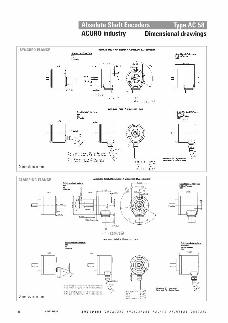
146 E N C O D E R S C O U N T E R S I N D I C A T O R S R E L A Y S P R I N T E R S C U T T E R S
Absolute Shaft EncodersACURO industry
Type AC 58Dimensional drawings
SYNCHRO FLANGE
CLAMPING FLANGE
48 ± 0.3
Dimensions in mm
Dimensions in mm

147E N C O D E R S C O U N T E R S I N D I C A T O R S R E L A Y S P R I N T E R S C U T T E R S
Absolute Shaft EncodersACURO industry
Type AC 58 Dimensional drawings
HOLLOW SHAFT
SQUARE FLANGE
L = Immersion depth of shaft in encoderDimensions in mm
Dimensions in mm

148 E N C O D E R S C O U N T E R S I N D I C A T O R S R E L A Y S P R I N T E R S C U T T E R S
Absolute Shaft EncodersACURO industry
Type AC 58Dimensional drawings
SYNCHRO FLANGE („S“)
BUS COVERS
Connection: „I“
Connection: „R“ Connection: „S“
Connection: „T“ Connection: „Z“
Dimensions in mm
Dimensions in mm

149E N C O D E R S C O U N T E R S I N D I C A T O R S R E L A Y S P R I N T E R S C U T T E R S
CLAMPING FLANGE („K“)
HOLLOW SHAFT („F“)
Dimensions
Absolute Shaft EncodersACURO industry
Type AC 58 Dimensional drawings
L = Immersion depth of shaft in encoder
Dimensions in mm
Dimensions in mm

150 E N C O D E R S C O U N T E R S I N D I C A T O R S R E L A Y S P R I N T E R S C U T T E R S
Absolute Shaft EncodersACURO industry
Type AC 58Dimensional drawings
SQUARE FLANGE (“Q”)
Dimensions in mm

151E N C O D E R S C O U N T E R S I N D I C A T O R S R E L A Y S P R I N T E R S C U T T E R S
Absolute Shaft EncodersACURO industry
Type AC 110BiSS / SSI
■ Same electrical performance as ACURO industry AC 36 and AC 58 versions
■ Robust bearings for long life■ Hollow shaft up to 50 mm■ Absolute singleturn■ Revolution 11-17 Bit■ SSI or BiSS - Interface■ Optional: Sine-Cosine 4096 increments■ DC 5 V or DC 10 - 30 V■ Integrated diagnostic system
TECHNICAL DATAmechanical
Housing diameter 110 mm Shaft diameter up to 50 mm Protection class housing IP50 or IP64Protection class shaft IP50 or IP64Max. speed IP50: 3 600 min-1
IP64: 1 500 min-1
Spring tether (hollow shaft)Tolerance axial ± 0.5 mmTolerance radial ± 0.05 mmVibration resistance (IEC 68-2-6) 100 m/ s2 (10 - 500 Hz)Shock resistance (IEC 68-2-27) 1000 m/ s2 (6 ms) Operating temperature -20...+70°CStorage temperature -50...+80°CMaterial Shaft Stainless steelMaterial Housing AluminiumWeight approx. 1000g
HENGSTLER OPTOASIC Technology
The central Element of the ACURO AC110 is the latest Hengstler OptoAsic technology, whichoffers the following key benefits.
• Outstanding reliability by reduced number of components and integrated diagnostics systems
• Aging compensation by integrated LED light regulation
• Integrated monitoring of: - Pollution- Disk damage- LED lifetime- Temperature
The ACURO AC110 is ideally suited for applications like: • Gearless drive• Gearless elevators• Industrial Machinery
GENERAL INFORMATION
PPRREELLIIMMIINNAARRYY

152 E N C O D E R S C O U N T E R S I N D I C A T O R S R E L A Y S P R I N T E R S C U T T E R S
TECHNICAL DATAelectrical
Supply voltage DC 5 V (–5 %/ +10 %) or DC 10-30 VMax. current w/o load ST/MT 120 mALines / Drives Clock and Data / RS422Output code Binary or GrayResolution singleturn 10 - 17 BitIncremental signals Sine - Cosine 1 Vpp
No. of increments 4 0963 dB limiting frequency 500 kHzAbsolute accuracy ± 35“Repeatability ± 7“
Alarm output alarm bit (SSI),warning bit and alarm bit (BiSS)
Connection Cable radialCable with Conin-Coupling
Absolute Shaft EncodersACURO industry
Type AC 110BiSS / SSI
DIMENSIONAL DRAWINGS KEYWAY
CLAMPING RING
Shaft codeUnitDimension
Shaft
Dimensions in mm
Dimensions in mm

153E N C O D E R S C O U N T E R S I N D I C A T O R S R E L A Y S P R I N T E R S C U T T E R S
Absolute Shaft EncodersACURO industry
Type AC 110BiSS / SSI
ORDERING INFORMATION
Supply voltage
SpringtetherResolution ConnectionType
A DC 5 V 2E DC 10 - 30 V
B withO without
0011 11 Bit ST0012 12 Bit ST0013 13 Bit ST0014 14 Bit ST 0017 17 Bit ST 1
AC110 B Cable radial 1.5 mB-D0 Cable radial 3 mB-F0 Cable radial 5 mB-K0 Cable radial 10 mB-D Cable 1.5 m with
Conin-Coupling
.Protectionclass
1 IP504 IP64
Mounting /Shaft
K50 Keyway (4x1.2)/50 mm
H50 Clamping ring/ 50 mm
Output
SB SSIBinary
SG SSI GrayBI BiSS
PIN ASSIGNMENT Colour cable Cable Signalconnector
brown 4 1 0 V (supply voltage)pink 2 Datayellow 3 Clock
4 N.C.blue 5 1
6 N.C.7 N.C.
white 4 8 DC 5 V 3/ DC 10 - 30 V9 N.C.
grey 10green 11black 12 0 V-signal output 2
Screen Shielded with housing
ClockData
Direction
1 Direction: + UB or unconnected = ascending code values with rotation cw0 V = descending code values with rotation cw
2 Connected with 0 V in the encoder. Use this output to lay Direction on logical “0”if required.
3 Notice: when supply voltage = DC 5V ➞ max. cable length 10 m4 Use only thin wires 014 mm2
1 When resolution > 14 Bit ➞ max. Clock frequency 178´kHz2 Notice: when supply voltage = DC 5V ➞ max. cable length 10 m
The max. data transfer rate depends on the cable length. For Clock / and Data / please use twisted pairs. Use shielded cable.DataClock
Lead length Baud rate< 50 m < 400 kHz< 100 m < 300 kHz< 200 m < 200 kHz< 400 m < 100 kHz
RECOMMENDED DATA TRANSFER RATE WITH SSI

154 E N C O D E R S C O U N T E R S I N D I C A T O R S R E L A Y S P R I N T E R S C U T T E R S
Absolute Shaft Encoders Type AC 59 / 61Stainless steel
■ Compact design■ Protection class IP67■ High corrosion resistance■ Robust design■ Resolution up to 29 Bit (17 Bit ST, 12 Bit MT)■ Connection with cable or with bus cover■ Applications:
- Packaging machine for food and beverage- Ship equipment (e.g. cranes, winches, cable laying ships)- Offshore - Applications
The absolute stainless steel encoder are available in the Versions AC 59 and AC 61 ■ AC 59: drawn stainless steel housing, only together with cable outlet,
no access to control elements ■ AC 61: massive turned housing, possible with cable or bus cover,
access to control elements (DIP switch, Reset switch)
TYPES The stainless steel encoder is available with following interfaces: ■ Single- or multiturn with cable radial/ axial and interfaces SSI, BiSS, Parallel, SSI-P,
CANopen, CANlayer2■ Single- or multiturn with bus cover and interfaces Profibus, CANopen, CANlayer2,
DeviceNet, Interbus
Version AC 61 with bus cover or cable
Version AC 59 with cable outlet
TECHNICAL DATAelectrical
The electrical data and pin assignment see for:
■ BiSS/ SSI, page 113■ Parallel, page 118■ Profibus, page 123■ CANopen, page 127
TECHNICAL DATAmechanical
Flange Square flange 63.5 x 63.5 mmShaft diameter 10 mmProtection class (EN 60529) IP67Max. Speed Short term: 10 000 min-1 , continuous: 6 000 min-1
Torque < 1 NcmMoment or inertia approx. 20 gcm2
Max. shaft load axial 40 N/ radial 60 NVibration proof (IEC 68-2-6) 100 m/ s2 (10 - 500 Hz)Shock resistance (IEC 68-2-27) 1000 m/ s2 (6 ms)Operating temperature SSI, BiSS, Parallel, : -40...+100°C
SSI-P, Interbus: -40...+70°C Profibus, CANopen, CANlayer2, DeviceNet: -40...+ 85°C
Storage temperature -40...+ 85°C Material Shaft/ Housing Stainless steelWeight approx. AC 59 with 1.5 m cable: 700 g
AC 61 with 1.5 m cable: 980 gAC 61 with bus cover (MT): 1 180 g
■ CANlayer2, page 130■ DeviceNet, page 133■ Interbus, page 136■ SSI-P, page 142

155E N C O D E R S C O U N T E R S I N D I C A T O R S R E L A Y S P R I N T E R S C U T T E R S
Absolute Shaft Encoders Type AC 59 / 61Stainless steel
DIMENSIONAL DRAWINGS
AC 59
AC 61
Dimensions in mm
Dimensions in mm

DIMENSIONAL DRAWINGS (continued)
156 E N C O D E R S C O U N T E R S I N D I C A T O R S R E L A Y S P R I N T E R S C U T T E R S
Absolute Shaft Encoders Type AC 59 / 61Stainless steel
AC 61
AC 61
Dimensions in mm
Dimensions in mm
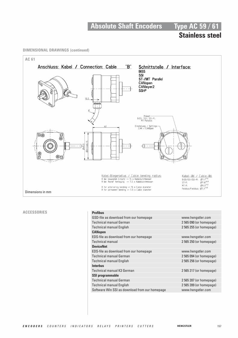
157E N C O D E R S C O U N T E R S I N D I C A T O R S R E L A Y S P R I N T E R S C U T T E R S
Absolute Shaft Encoders Type AC 59 / 61Stainless steel
DIMENSIONAL DRAWINGS (continued)
AC 61
ACCESSORIES ProfibusGSD-file as download from our homepage www.hengstler.comTechnical manual German 2 565 090 (or homepage)Technical manual English 2 565 255 (or homepage)CANopenEDS-file as download from our homepage www.hengstler.comTechnical manual 2 565 250 (or homepage)DeviceNetEDS-file as download from our homepage www.hengstler.com Technical manual German 2 565 094 (or homepage)Technical manual English 2 565 256 (or homepage)InterbusTechnical manual K3 German 2 565 217 (or homepage)SSI programmableTechnical manual German 2 565 287 (or homepage)Technical manual English 2 565 289 (or homepage)Software Win SSI as download from our homepage www.hengstler.com
Dimensions in mm

158 E N C O D E R S C O U N T E R S I N D I C A T O R S R E L A Y S P R I N T E R S C U T T E R S
Absolute Shaft Encoders Type AC 59 / 61Stainless steel
1 with Offset 76 (value range 76...435)2 with Offset 152 (value range 152...871)
ORDERING INFORMATIONACURO industry with BiSS
Supplyvoltage Flange, Protection, ShaftResolutionType
A DC 5 VE DC 10 - 30 V
Q.72 Square flange, IP67,10x19.5 mm
Q.76 Square flange, IP67,9.52x19.5 mm
0010 10 Bit ST0012 12 Bit ST 0013 13 Bit ST0014 14 Bit ST 0017 17 Bit ST0360 360 Incr. ST 10720 720 Incr. ST 21212 12 Bit MT+12 Bit ST1213 12 Bit MT+13 Bit ST 1214 12 Bit MT+14 Bit ST1217 12 Bit MT+17 Bit ST
AC59
Output Connection
BI BiSS (Digital)
BC BiSS (+SinCos 1Vpp)
A Cable axial 1.5 mA-F0 Cable axial 5 mA-K0 Cable axial 10 mB Cable radial 1.5 mB-F0 Cable radial 5 mB-K0 Cable radial 10 m
1 with Offset 76 (value range 76...435)2 with Offset 152 (value range 152...871)
ORDERING INFORMATIONACURO industry with SSI
Supplyvoltage Flange, Protection, ShaftResolutionType
A DC 5 VE DC 10 - 30 V
Q.72 Square flange, IP67,10x19.5 mm
Q.76 Square flange, IP67,9.52x19.5 mm
0010 10 Bit ST0012 12 Bit ST 0013 13 Bit ST0014 14 Bit ST 0017 17 Bit ST0360 360 Incr. ST 10720 720 Incr. ST 21212 12 Bit MT+12 Bit ST1213 12 Bit MT+13 Bit ST
AC59
Output Connection
SB SSI BinarySG SSI GraySC SSI Gray
(+SinCos 1Vpp)
A Cable axial 1.5 mA-F0 Cable axial 5 mA-K0 Cable axial 10 mB Cable radial 1.5 mB-F0 Cable radial 5 mB-K0 Cable radial 10 m

159E N C O D E R S C O U N T E R S I N D I C A T O R S R E L A Y S P R I N T E R S C U T T E R S
Absolute Shaft Encoders Type AC 59 / 61Stainless steel
* only with ST1 with Offset 76 (value range 76...435)2 with Offset 152 (value range 152...871)
ORDERING INFORMATIONACURO industry with Parallel
Supplyvoltage Flange, Protection, ShaftResolutionType
E DC 10 - 30 V Q.72 Square flange, IP67,10x19.5 mm
Q.76 Square flange, IP67,9.52x19.5 mm
0010 10 Bit ST0012 12 Bit ST 0013 13 Bit ST0014 14 Bit ST 0017 17 Bit ST0360 360 Incr. ST 10720 720 Incr. ST 20412 04 Bit MT+12 Bit ST0812 08 Bit MT+12 Bit ST 1212 12 Bit MT+12 Bit ST
AC59 *AC61
Output Connection
PB Parallel BinaryPG Parallel Gray
A Cable axial 1.5 mA-F0 Cable axial 5 mA-K0 Cable axial 10 mB Cable radial 1.5 mB-F0 Cable radial 5 mB-K0 Cable radial 10 m
ORDERING INFORMATIONACURO industry with Profibus
Supplyvoltage Flange, Protection, ShaftResolutionType
E DC 10 - 30 V Q.72 Square flange, IP67,10x19.5 mm
Q.76 Square flange, IP67,9.52x19.5 mm
0010 10 Bit ST0012 12 Bit ST 0013 13 Bit ST0014 14 Bit ST 1212 12 Bit MT+12 Bit ST1213 12 Bit MT+13 Bit ST 1214 12 Bit MT+14 Bit ST
AC61
Output Connection
DP Profibus Z Bus terminal box with3x screwed cablegland
ORDERING INFORMATIONACURO industry with CANopen / CANlayer2
Supplyvoltage Flange, Protection, ShaftResolutionType
E DC 10 - 30 V Q.72 Square flange, IP67,10x19.5 mm
Q.76 Square flange, IP67,9.52x19.5 mm
0010 10 Bit ST0012 12 Bit ST 0013 13 Bit ST0014 14 Bit ST 1212 12 Bit MT+12 Bit ST1213 12 Bit MT+13 Bit ST 1214 12 Bit MT+14 Bit ST
AC61
Output Connection
OL CANopenCL CANlayer2
A Cable axial 1.5 mA-F0 Cable axial 5 mA-K0 Cable axial 10 mB Cable radial 1.5 mB-F0 Cable radial 5 mB-K0 Cable radial 10 mZ Bus terminal box
with 3x screwed cable gland
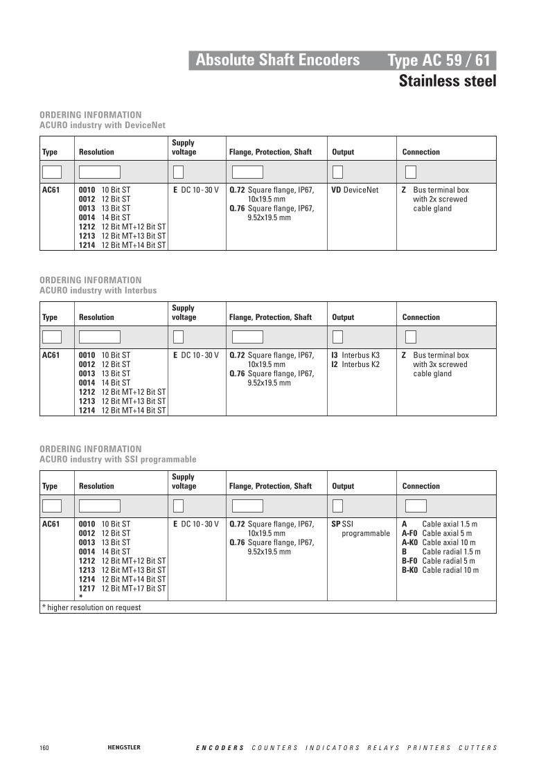
160 E N C O D E R S C O U N T E R S I N D I C A T O R S R E L A Y S P R I N T E R S C U T T E R S
Absolute Shaft Encoders Type AC 59 / 61Stainless steel
ORDERING INFORMATIONACURO industry with DeviceNet
Supplyvoltage Flange, Protection, ShaftResolutionType
E DC 10 - 30 V Q.72 Square flange, IP67,10x19.5 mm
Q.76 Square flange, IP67,9.52x19.5 mm
0010 10 Bit ST0012 12 Bit ST 0013 13 Bit ST0014 14 Bit ST 1212 12 Bit MT+12 Bit ST1213 12 Bit MT+13 Bit ST 1214 12 Bit MT+14 Bit ST
AC61
Output Connection
VD DeviceNet Z Bus terminal box with 2x screwed cable gland
ORDERING INFORMATIONACURO industry with Interbus
Supplyvoltage Flange, Protection, ShaftResolutionType
E DC 10 - 30 V Q.72 Square flange, IP67,10x19.5 mm
Q.76 Square flange, IP67,9.52x19.5 mm
0010 10 Bit ST0012 12 Bit ST 0013 13 Bit ST0014 14 Bit ST 1212 12 Bit MT+12 Bit ST1213 12 Bit MT+13 Bit ST 1214 12 Bit MT+14 Bit ST
AC61
Output Connection
I3 Interbus K3I2 Interbus K2
Z Bus terminal box with 3x screwed cable gland
ORDERING INFORMATIONACURO industry with SSI programmable
Supplyvoltage Flange, Protection, ShaftResolutionType
E DC 10 - 30 V Q.72 Square flange, IP67,10x19.5 mm
Q.76 Square flange, IP67,9.52x19.5 mm
0010 10 Bit ST0012 12 Bit ST 0013 13 Bit ST0014 14 Bit ST 1212 12 Bit MT+12 Bit ST1213 12 Bit MT+13 Bit ST 1214 12 Bit MT+14 Bit ST1217 12 Bit MT+17 Bit ST*
AC61
Output Connection
SP SSI programmable
A Cable axial 1.5 mA-F0 Cable axial 5 mA-K0 Cable axial 10 mB Cable radial 1.5 mB-F0 Cable radial 5 mB-K0 Cable radial 10 m
* higher resolution on request

161E N C O D E R S C O U N T E R S I N D I C A T O R S R E L A Y S P R I N T E R S C U T T E R S
Absolute Shaft Encoders Type AX 70 / 71 Explosion proof
EX-CLASSIFICATION
T6 = Highest permissible surface temperature +85°C (max. speed = 6000 U/min-1)T4 = Highest permissible surface temperature +130°C(max. speed = 10000 U/min-1)
■ ATEX certification for gas and dust explosion proof■ Same electrical performance as ACURO industry■ Protection class up to IP67■ Diameter only 70 mm ■ Robust design■ Also available with stainless steel■ Resolution up to 29 Bit (17 Bit ST, 12 Bit MT)■ Applications:
- enamelling production line- petro chemistry - bottling machines- mixers- silo works, mills
■ Interfaces: SSI, SSI programmable, Profibus, CANopen
II 2 G/D E Ex d II C T6/T4 IP65/ IP66 135°C res. 85°C
Temperature class T4 resp. T6*
Gas group C (e.g. methane; ignition energy < 60μJ)
Explosion group ll
Explosion proof enclosure
Explosion-proof operating material
Build to European specifications
For use in areas with gas, vapours, mist, cloud of dust
Category 2
Device group llI (all area expect mining)
Explosion proof enclosure with Declaration of Conformity
Version AX 70 - Aluminium
Version AX 71 - Stainless steel
The absolute shaft encoder line ACURO is available in explosion proof design with explosion proof enclosure “d” under AX 70 and AX 71 (stainless steel). The PTB has assured with the Declaration of Conformity that the AX 70 / 71 meets the requirements of safety and health according to EN 50014 and EN 50018. Therefore it is approved in explosive areas, code „Ex ll 2 G/D E Ex d ll C T4/T6 IP65/ IP66 135°C resp. 85°C“.For applications under tough environmental conditions and food industry the stainless steel version AX 71 is available.
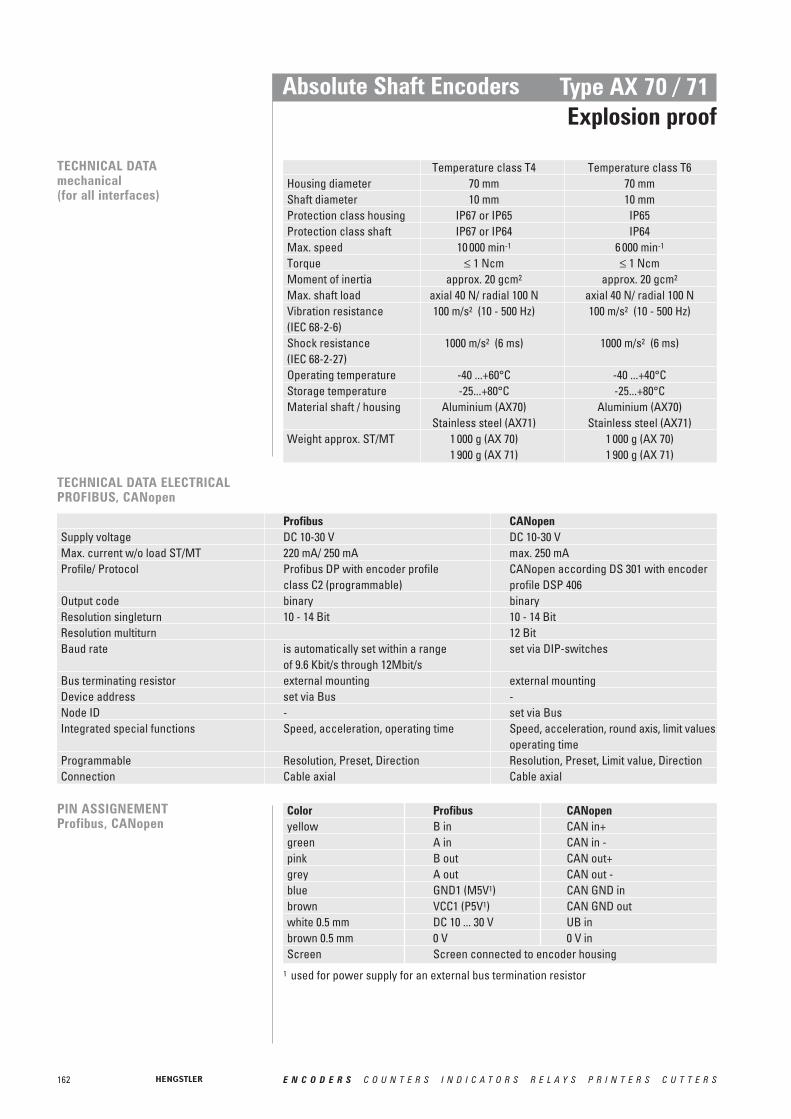
162 E N C O D E R S C O U N T E R S I N D I C A T O R S R E L A Y S P R I N T E R S C U T T E R S
Absolute Shaft Encoders Type AX 70 / 71 Explosion proof
TECHNICAL DATAmechanical(for all interfaces)
Temperature class T4 Temperature class T6Housing diameter 70 mm 70 mm Shaft diameter 10 mm 10 mmProtection class housing IP67 or IP65 IP65Protection class shaft IP67 or IP64 IP64Max. speed 10 000 min-1 6 000 min-1
Torque ≤ 1 Ncm ≤ 1 NcmMoment of inertia approx. 20 gcm2 approx. 20 gcm2
Max. shaft load axial 40 N/ radial 100 N axial 40 N/ radial 100 NVibration resistance 100 m/s2 (10 - 500 Hz) 100 m/s2 (10 - 500 Hz)(IEC 68-2-6)Shock resistance 1000 m/s2 (6 ms) 1000 m/s2 (6 ms)(IEC 68-2-27)Operating temperature -40 ...+60°C -40 ...+40°CStorage temperature -25...+80°C -25...+80°CMaterial shaft / housing Aluminium (AX70) Aluminium (AX70)
Stainless steel (AX71) Stainless steel (AX71)Weight approx. ST/MT 1 000 g (AX 70) 1 000 g (AX 70)
1 900 g (AX 71) 1 900 g (AX 71)
TECHNICAL DATA ELECTRICALPROFIBUS, CANopen
Profibus CANopenSupply voltage DC 10-30 V DC 10-30 VMax. current w/o load ST/MT 220 mA/ 250 mA max. 250 mAProfile/ Protocol Profibus DP with encoder profile CANopen according DS 301 with encoder
class C2 (programmable) profile DSP 406Output code binary binaryResolution singleturn 10 - 14 Bit 10 - 14 BitResolution multiturn 12 BitBaud rate is automatically set within a range set via DIP-switches
of 9.6 Kbit/s through 12Mbit/sBus terminating resistor external mounting external mountingDevice address set via Bus -Node ID - set via BusIntegrated special functions Speed, acceleration, operating time Speed, acceleration, round axis, limit values
operating timeProgrammable Resolution, Preset, Direction Resolution, Preset, Limit value, DirectionConnection Cable axial Cable axial
PIN ASSIGNEMENTProfibus, CANopen
Color Profibus CANopenyellow B in CAN in+green A in CAN in -pink B out CAN out+grey A out CAN out -blue GND1 (M5V1) CAN GND inbrown VCC1 (P5V1) CAN GND outwhite 0.5 mm DC 10 ... 30 V UB inbrown 0.5 mm 0 V 0 V inScreen Screen connected to encoder housing
1 used for power supply for an external bus termination resistor

163E N C O D E R S C O U N T E R S I N D I C A T O R S R E L A Y S P R I N T E R S C U T T E R S
Absolute Shaft Encoders Type AX 70 / 71 Explosion proof
PIN ASSIGNMENTSSI, SSI programmable
Color No. SSI SSI programmablewhite 0.14 mm 6 DC 10 ... 30 V RS232 RxDbrown 0.14 mm 5 0 V supply voltage RS232 TxDgreen 10yellow 9 Clock Clockgrey 8pink 7 Data Datablue 3 Directionblack 4 0 V signal output 0 V signal outputred 1 - Preset 1violet 2 - Preset 2brown 0.5 mm 11 - 0 V supply voltagewhite 0.5 mm 12 - DC 10 ... 30 VScreen Screen connected to the housing
Direction
DataData
ClockClock
TECHNICAL DATA ELECTRICALSSI, SSI PROGRAMMABLE
SSI SSI programmableSupply voltage DC 10-30 V DC 10-30 VMax. current w/o load ST/MT 220 mA/ 250 mA max. 250 mALines / Drivers clock and data RS422 clock and data RS422Output code binary or gray binary or grayResolution singleturn 10 - 17 Bit 9 - 22 BitResolution multiturn 12 Bit 12 BitProgrammable (with ACURO soft + code type, direction, warning, -appropriate hardware) alarmProgrammable (with WIN SSI) - code type, direction, output code,
warning, alarmControl input Direction, Preset 1, Preset 2Alarm output Alarm bit Alarm bitConnection Cable axial Cable axial
Direction
The max. data transfer rate depends on the cable length. For Clock / and Data / please use twisted pairs. Use shielded cable.DataClock
Lead length Baud rate< 50 m < 400 kHz< 100 m < 300 kHz< 200 m < 200 kHz< 400 m < 100 kHz
RECOMMENDED DATA TRANSFER RATE WITH SSI
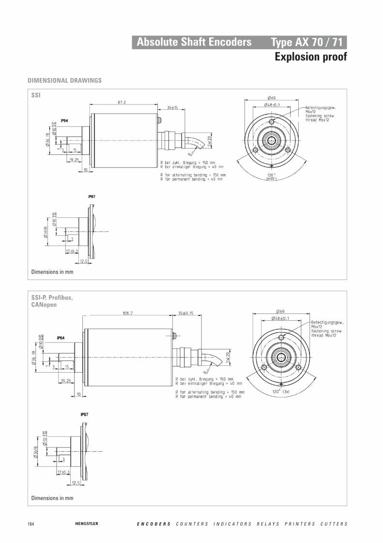
164 E N C O D E R S C O U N T E R S I N D I C A T O R S R E L A Y S P R I N T E R S C U T T E R S
Absolute Shaft Encoders Type AX 70 / 71 Explosion proof
DIMENSIONAL DRAWINGS
SSI
SSI-P, Profibus,CANopen
Dimensions in mm
Dimensions in mm
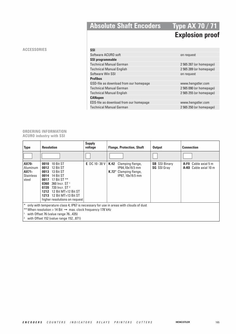
165E N C O D E R S C O U N T E R S I N D I C A T O R S R E L A Y S P R I N T E R S C U T T E R S
Absolute Shaft Encoders Type AX 70 / 71 Explosion proof
ACCESSORIES SSISoftware ACURO soft on requestSSI programmableTechnical Manual German 2 565 287 (or homepage)Technical Manual English 2 565 289 (or homepage)Software Win SSI on requestProfibusGSD-file as download from our homepage www.hengstler.comTechnical Manual German 2 565 090 (or homepage)Technical Manual English 2 565 255 (or homepage)CANopenEDS-file as download from our homepage www.hengstler.comTechnical Manual German 2 565 250 (or homepage)
* only with temperature class 4; IP67 is necessary for use in areas with clouds of dust ** When resolution > 14 Bit ➞ max. clock frequency 178´kHz1 with Offset 76 (value range 76...435)2 with Offset 152 (value range 152...871)
ORDERING INFORMATIONACURO industry with SSI
Supplyvoltage Flange, Protection, ShaftResolutionType
E DC 10 - 30 V K.42 Clamping flange, IP64,10x19.5 mm
K.72* Clamping flange,IP67, 10x19.5 mm
0010 10 Bit ST0012 12 Bit ST 0013 13 Bit ST0014 14 Bit ST0017 17 Bit ST **0360 360 Incr. ST 10720 720 Incr. ST 21212 12 Bit MT+12 Bit ST1213 12 Bit MT+13 Bit SThigher resolutions on request
AX70-AluminumAX71-Stainlesssteel
Output Connection
SB SSI BinarySG SSI Gray
A-F0 Cable axial 5 mA-K0 Cable axial 10 m
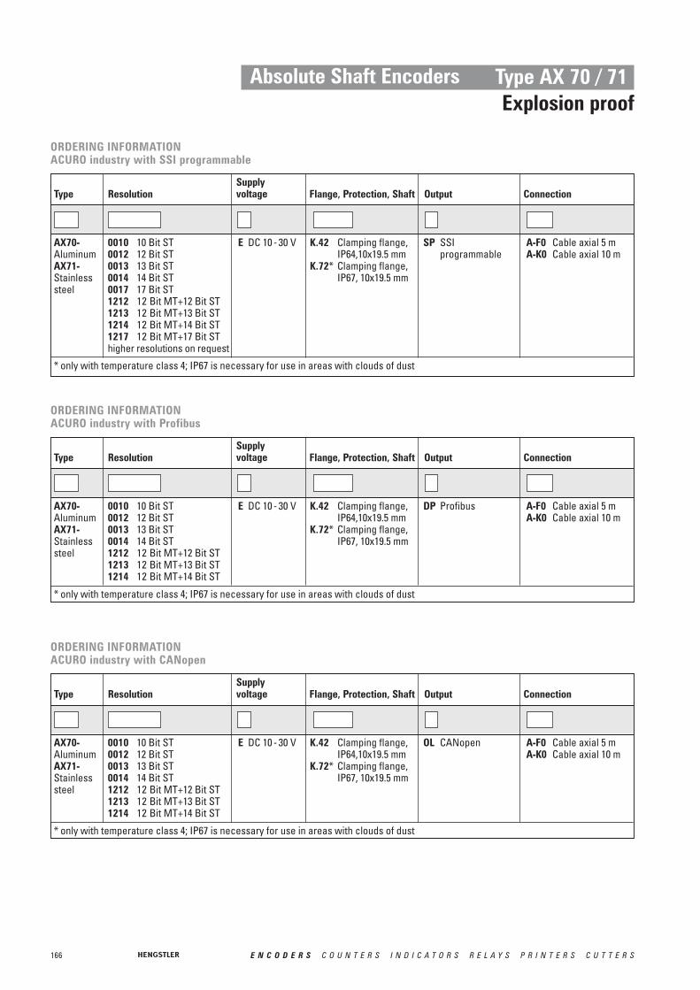
166 E N C O D E R S C O U N T E R S I N D I C A T O R S R E L A Y S P R I N T E R S C U T T E R S
Absolute Shaft Encoders Type AX 70 / 71Explosion proof
* only with temperature class 4; IP67 is necessary for use in areas with clouds of dust
ORDERING INFORMATIONACURO industry with SSI programmable
Supplyvoltage Flange, Protection, ShaftResolutionType
E DC 10 - 30 V K.42 Clamping flange, IP64,10x19.5 mm
K.72* Clamping flange,IP67, 10x19.5 mm
0010 10 Bit ST0012 12 Bit ST 0013 13 Bit ST0014 14 Bit ST0017 17 Bit ST1212 12 Bit MT+12 Bit ST1213 12 Bit MT+13 Bit ST1214 12 Bit MT+14 Bit ST1217 12 Bit MT+17 Bit SThigher resolutions on request
AX70-AluminumAX71-Stainlesssteel
Output Connection
SP SSI programmable
A-F0 Cable axial 5 mA-K0 Cable axial 10 m
* only with temperature class 4; IP67 is necessary for use in areas with clouds of dust
ORDERING INFORMATIONACURO industry with Profibus
Supplyvoltage Flange, Protection, ShaftResolutionType
E DC 10 - 30 V K.42 Clamping flange, IP64,10x19.5 mm
K.72* Clamping flange,IP67, 10x19.5 mm
0010 10 Bit ST0012 12 Bit ST 0013 13 Bit ST0014 14 Bit ST1212 12 Bit MT+12 Bit ST1213 12 Bit MT+13 Bit ST1214 12 Bit MT+14 Bit ST
AX70-AluminumAX71-Stainlesssteel
Output Connection
DP Profibus A-F0 Cable axial 5 mA-K0 Cable axial 10 m
* only with temperature class 4; IP67 is necessary for use in areas with clouds of dust
ORDERING INFORMATIONACURO industry with CANopen
Supplyvoltage Flange, Protection, ShaftResolutionType
E DC 10 - 30 V K.42 Clamping flange, IP64,10x19.5 mm
K.72* Clamping flange,IP67, 10x19.5 mm
0010 10 Bit ST0012 12 Bit ST 0013 13 Bit ST0014 14 Bit ST1212 12 Bit MT+12 Bit ST1213 12 Bit MT+13 Bit ST1214 12 Bit MT+14 Bit ST
AX70-AluminumAX71-Stainlesssteel
Output Connection
OL CANopen A-F0 Cable axial 5 mA-K0 Cable axial 10 m

167E N C O D E R S C O U N T E R S I N D I C A T O R S R E L A Y S P R I N T E R S C U T T E R S
Mot
or F
eedb
ack
Syst
ems
Motor Feedback Systems
Hengstler offers Motor Feedback systems in all performance classesand with the most commonly used interfaces
From modular miniature incremental encoders for DC and StepperMotors in 22 mm diameter up to the absolute AC110 with 50mm hollow shaft Hengstler provides a complete range of MotorFeedback systems.
For asynchronous motors and elevators the offering comprisesincremental and absolute hollow shaft encoders in singleturn andmultiturn versions. Trend-setting is the Incremental OptoAsic withdiagnosis system and integrated interpolation electronic which is forthe first time used in RI80-E. This enables resolutions of up to 200 000pulses for good synchronism of electric machines running at lowrevs.
For AC Servo Motors there is an extensive range of feedback products available: Brushless resolvers size 10, 15 and 21 uniquelyrobust and low priced, incremental comcoders for direct block commutation of BLDC motors in low cost modular version or withintegrated bearings and resolutions up to 10 000 pulses per revolution.
Your application requires highest precision and dynamics? Than youare on the right track with the Sine-wave encoder S21 and the absolute Acuro-Drive encoder. Latest OptoAsic technology and atrue geared multiturn provides obvious advantages regarding performance and reliability. Hengstler offers the Acuro-Drives serieswith the open, highspeed, digital interface BiSS. With the opensource BiSS interface the proprietary lock-in situation with absolutemotorfeedback systems is broken up with the benefit of an increasing range of suppliers.
One Size fits all:No matter whether your servo application requires resolvers, incremental comcoders or absolute Multiturn encoders - the com-plete range in size 15 with resolver compatible mounting is availablefrom Hengstler. The benefit of this is, that the B-side of the motor canbe resolver style and doesn't need to be customized, depending on thefeedback. The Feedback type can be selected according to customer demands or required resolution and technology. This helpsreducing variation of parts and stock and enables improved deliverytimes.

168 E N C O D E R S C O U N T E R S I N D I C A T O R S R E L A Y S P R I N T E R S C U T T E R S
Motor Feedback Systems - Kit Encodersfor Miniature DC and Stepper Motors
Special features
Number of pulsesCommutation
Technical Data - mechanicalShaft diameterMax. speedProtection class housing/bearingOperating temperatureDiameterMounting depth
Technical Data - electricalOutputSupply voltage (SELV)Max. current w/o load
Max. pulse frequencyMax. output load
Pulse shapePhasingSymmetry
■ ideal for position and speedsensing in small machines and actuators
■ 200 kHz operating frequency■ resolution to 512 lines/rev
100 ... 512None
Hollow shaft Ø 1.5 ... 4.0 mm12 000 min-1
----40 ... + 100 °C22.0 mm14.8 mm
TTLDC 5 V ±10 %10 mA, typ.
200 kHz3 mA (25°C),2 mA (100°C)Square wave90°±18° electrical180°±18° electrical
■ ideal economical feedback device for servo and stepper motors
■ short axial length and compact 1.5 inch diameter
■ easy "snap-on" installation■ high resolution to
1024 lines/rev and 200 kHz bandwidth
■ drop-in replacement for HP 5540
200 ... 1 024None
Hollow shaft Ø 3.0 ... 8.0 mm12 000 min-1
----40 ... + 100 °C38.0 mm17.2 mm
TTLDC 5 V ±10 %10 mA, typ.
200 kHz6mA (25°C)4 mA (100°C)Square wave90°±18° electrical180°±18° electrical
Type M 9 M 14
Page 183180
■ ideal for position and speed sensing in small machines and actuators
■ low power standby mode is ideal for battery powered devices
■ 200 kHz operating frequency■ resolution to 512 lines/rev
100 ... 512None
Hollow shaft Ø 1.5 ... 4.0 mm12 000 min-1
----40 ... + 100 °C22.0 mm20.0 mm
TTLDC 5 V ±10 %10 mA, typ.Standby current: max. 50 μA200 kHz3 mA (25°C),2 mA (100°C)Square wave90°±18° electrical180°±18° electrical
E 9
186

169E N C O D E R S C O U N T E R S I N D I C A T O R S R E L A Y S P R I N T E R S C U T T E R S
Motor Feedback Systems - Hollow shaft Encodersfor Asynchronous & DC Motors
Special features
Number of pulsesCommutation
Technical Data - mechanicalShaft diameterMax. speedMax. speed (continuous)Protection class housing/bearingGeneral design
Operating temperatureDiameterMounting depth
Technical Data - electricalOutput
Supply voltage (SELV)Max. current w/o load
Max. pulse frequency
Max. output load
Pulse shape
■ direct mounting without coupling
■ flexible hollow shaft concept up to 14 mm
■ through hollow shaft or as end shaft (blind shaft)
■ easy mounting procedure with clamping flange or fastening thread
■ short mounting depth of 33 mm■ operating temperature
up to 80 °C ■ Fixing of the flage with a
stator coupling or cylindric pin■ applications, e.g.
positioning drives, motors1 ... 5 000None
Hollow shaft 10 mm / 12 mm / 14 mm6 000 min-1
IP65/64as per DIN VDE 0160,protection class III-10 ... +70 °C58 mm33 mm .. 50.5 mm(depends on version)
RS 422 / push-pull / push-pullcomplementaryDC 5 V / DC 10 - 30 V40 mA (DC 5 V), 30 mA (DC 24 V),60 mA (DC 10 V)300 kHz (RS 422)200 kHz (push-pull)RS 422: ±30 mApush-pull with short circuitprotection: 30 mA (DC 10 - 30 V)Square wave
■ direct mounting without coupling
■ flexible hollow shaft concept up to 14 mm
■ through hollow shaft or as end shaft (blind shaft)
■ easy mounting procedure with clamping flange or fastening thread
■ short mounting depth of 33 mm■ operating temperature up to
100 °C■ Fixing of the flage with a
stator coupling or cylindric pin■ applications, e.g.
positioning drives, motors4 ... 2 500None
Hollow shaft 10 mm / 12 mm / 14 mm6 000 min-1
IP65/64as per DIN VDE 0160,protection class III-25 .. +100 °C58 mm33 mm .. 50.5 mm (depends on version)
RS 422 / push-pull / push-pullcomplementaryDC 5 V / DC 10 - 30 V40 mA (DC 5 V), 30 mA (DC 24 V),60 mA (DC 10 V)300 kHz (RS 422)200 kHz (push-pull)RS 422: ±30 mApush-pull with short circuitprotection: 30 mA (DC 10 - 30 V)Square wave
Type RI 58-D RI 58TD
Page 6862
■ miniature industry encoder for high numbers of pulses
■ short mounting depth■ easy mounting procedure■ applications, e.g.
motors, machine tools, packaging machines, robots, automated SMD equipment
5 ... 3 600None
Hollow shaft 4 / 6 / 8 / 10 mm10 000 min-1
IP64/64as per DIN VDE 0160,protection class III-10 ... +70 °C36 mm39 mm
RS 422 / push-pull / push-pullcomplementaryDC 5 V / DC 10 - 30 V40 mA (DC 5 V), 30 mA (DC 24 V),60 mA (DC 10 V)300 kHz (RS 422)200 kHz (push-pull)RS 422: ±30 mApush-pull with short circuitprotection: 30 mA (DC 10 - 30 V)Square wave
RI 36-H
68

170 E N C O D E R S C O U N T E R S I N D I C A T O R S R E L A Y S P R I N T E R S C U T T E R S
Motor Feedback Systems - Hollow shaft Encodersfor Asynchronous & DC Motors
Special features
Number of pulses
Commutation
Technical Data - mechanicalShaft fixationCoupling
Shaft diameterMax. speedProtection class housing/bearingGeneral design
Operating temperatureConnectionDiameterWeight
Technical Data - electricalOutput
Supply voltage (SELV)Max. current w/o load
Max. pulse frequency
Max. output load
Alarm outputPulse shapePulse duty factor
Type
Page 74
■ through hollow shaft■ shaft diameters 15 to 42 mm■ external diameter only 76 mm■ simple installation with
clamping ring front or rear■ operating temperature
up to 100 °C■ applications e.g.
motors, printing machines, elevators
1 ... 10 000
None
Clamping ring front or rearstator coupling(hubshaft with tether)Hollow shaft 15 ... 42 mm6 000 min-1 (depends on version)IP50/40 (Option: IP65/64)as per DIN EN 61010, protectionclass III, Contamination level 2,over voltage class II-25 ... +100 °CCable radial76 mm320 ... 580 g (depends on version)
RS 422 / push-pull /push-pull complementaryDC 5 V / DC 10 - 30 V60 mA (DC 5 V), 60 mA (DC 10 V),35 mA (DC 24 V)300 kHz (RS 422)200 kHz (push-pull)RS 422: ±30 mApush-pull with short circuitprotection: 30 mA (DC 10 - 30 V)NPN-O.C. 5 mASquare wave1 : 1
RI 76TD
■ incremental Output■ 30...45 mm hollow shaft ■ rugged mechanical design■ unbreakable disc■ integrated diagnostic system■ wide voltage range
DC 5 … 30 V
1024, 2048, 4096other number of pulses on requestNone
Keyway, set screwSpring tether (single, double)
Hollow shaft 30 ... 45 mm3600 min-1 (IP50), 1500 min-1 (IP64)IP50, IP64as per DIN EN 61010, protectionclass III, Contamination level 2,over voltage class II-20 ... +70 °CSub-D 15p. / cable, radial
1 000 g
RS 422 / push-pull /push-pull complementaryDC 5 V ±10% or DC 5 - 30 V60 mA (DC 5 V), 60 mA (DC 10 V),35 mA (DC 24 V)600 kHz (RS 422)200 kHz (push-pull)RS 422: ±30 mApush-pull with short circuitprotection: 40 mA (DC 5 - 30 V)NPN-O.C. 5 mASquare wave1 : 1
RI 80-E
78
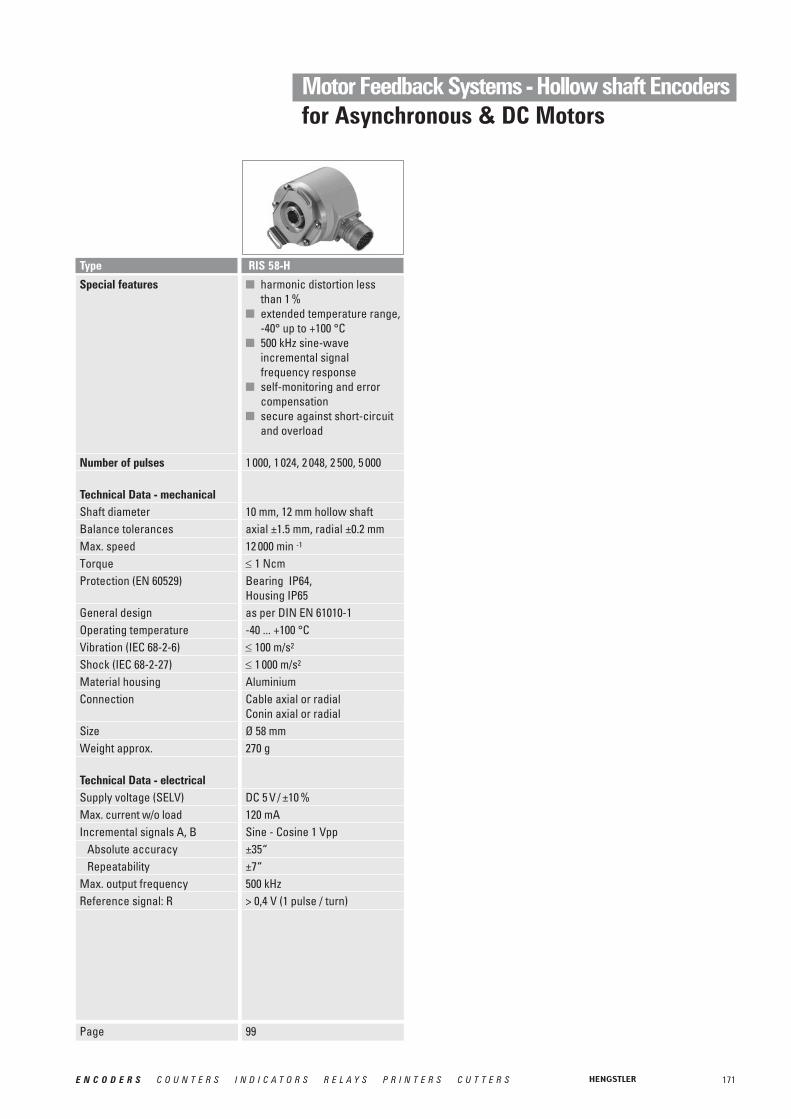
171E N C O D E R S C O U N T E R S I N D I C A T O R S R E L A Y S P R I N T E R S C U T T E R S
Motor Feedback Systems - Hollow shaft Encodersfor Asynchronous & DC Motors
Special features
Number of pulses
Technical Data - mechanicalShaft diameterBalance tolerances Max. speedTorqueProtection (EN 60529)
General designOperating temperatureVibration (IEC 68-2-6)Shock (IEC 68-2-27)Material housingConnection
SizeWeight approx.
Technical Data - electricalSupply voltage (SELV)Max. current w/o loadIncremental signals A, B
Absolute accuracyRepeatability
Max. output frequencyReference signal: R
Type
■ harmonic distortion less than 1 %
■ extended temperature range, -40° up to +100 °C
■ 500 kHz sine-wave incremental signal frequency response
■ self-monitoring and error compensation
■ secure against short-circuit and overload
1 000, 1 024, 2 048, 2 500, 5 000
10 mm, 12 mm hollow shaftaxial ±1.5 mm, radial ±0.2 mm12 000 min -1
≤ 1 NcmBearing IP64, Housing IP65as per DIN EN 61010-1-40 ... +100 °C≤ 100 m/s2
≤ 1 000 m/s2
AluminiumCable axial or radialConin axial or radialØ 58 mm270 g
DC 5 V / ±10 %120 mASine - Cosine 1 Vpp±35“±7“500 kHz> 0,4 V (1 pulse / turn)
RIS 58-H
Page 99

172 E N C O D E R S C O U N T E R S I N D I C A T O R S R E L A Y S P R I N T E R S C U T T E R S
Motor Feedback Systems - Hollow shaft Encodersfor Asynchronous & DC Motors
Technical Data - mechanicalHousing diameterShaft diameterProtection class shaft inputProtection class housingFlangeMax. speed
Shaft loadSpring tether (hollow shaft)Tolerance axial / radialShock resistance (IEC 68-2-27)Vibration resistance (IEC 68-2-6)Operating temperatureWeight approx. ST/MT
Technical Data - electricalSupply voltage
Max. current w/o load ST/MTInterfaceLines/ DrivesOutput codeLinearity
Resolution singleturn
Resolution multiturnOptional incremental signals
Number of pulses3 db limiting frequencyAbsolute accuracyRepeatability
Parameterization
Control inputReset keyAlarm output
Status LEDConnection
110 mm up to 50 mm IP50 or IP64IP50 or IP64Hollow shaft with tetherIP50: 3600 min-1
IP64: 1500 min-1
± 0.5 mm / ± 0.05 mm1000 m/ s2 (6 ms) 100 m/ s2 (10 - 500 Hz)-20 ...+70°C 1000 g
DC 5 V (–5 %/ +10 %) or DC 10-30 V120 mABiSS or Standard SSIClock and Data/ RS422Binary or Gray
10 - 17 Bit
only singleturnSine - Cosine 1 Vpp4096500 kHz± 35“± 7“Code type, sense of rotation,warning, alarm
Alarm bit (SSI option), warning bit and alarm bit (BiSS)
Cable radialCable with Conin-Coupling
Direction
Type AC 110 - BiSS / SSI
58 mmHub shaft 10 mm, 12 mmIP64 or IP67IP64 (IP67 optional)Hubshaft with tetherContinuous: 10 000 min-1,Short term: 12 000 min-1
axial 40 N / radial 60 N
± 1.5 mm/ ± 0.2 mm1 000 m/s2 (6 ms)100 m/s2 (10 ... 2 000 Hz)
-40 … 100 °C260 g / 310 g
DC 5 V, -5 % / + 10 % or DC 10 - 30 V50 mA / 100 mABiSS or Standard SSIClock and Data/ RS422Binary or Gray±1/2 LSB(± 1 LSB for resolution > 13 Bit)
10-17 Bit,Gray Excess: 360, 720 steps12 BitSine - Cosine 1 Vpp2048
±35“±7“Code type, sense of rotation,warning, alarm
Disable via parameterizationAlarm bit (SSI option), warning bit and alarm bit (BiSS)Green = OK.; red = alarmCable axial or radialConin axial or radialM12, 8 pole
Direction
AC 58 - BiSS / SSI
Page 113 151
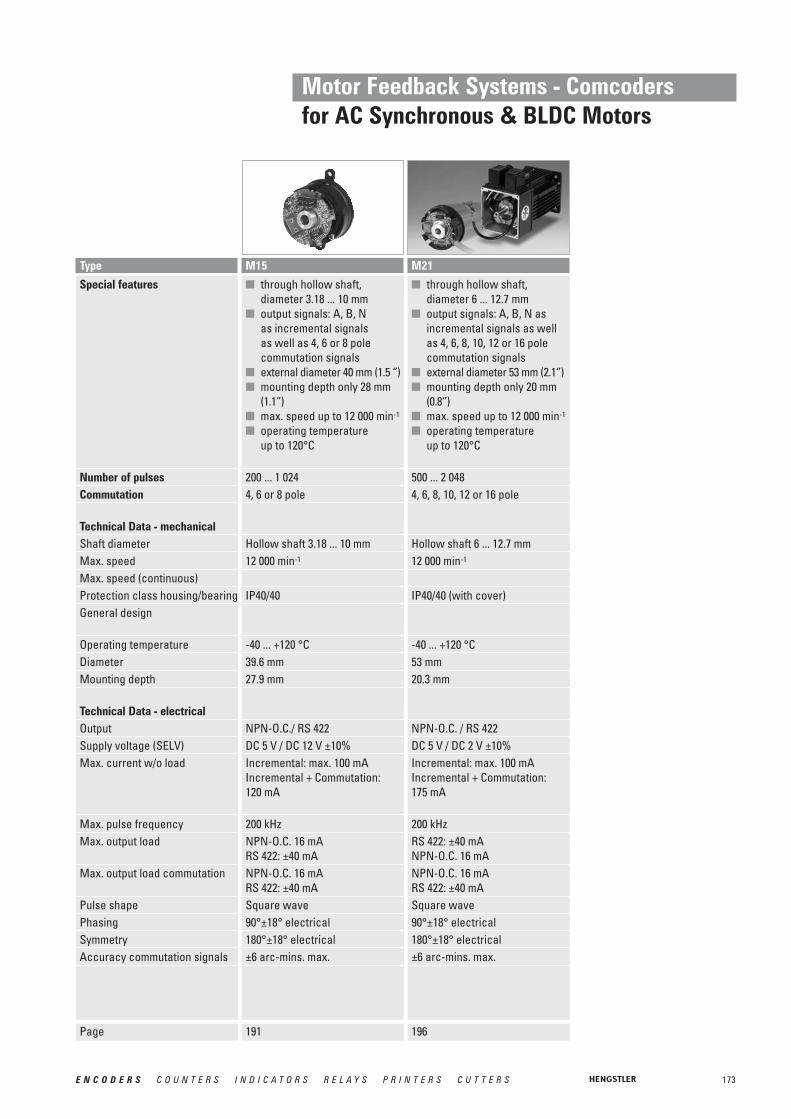
173E N C O D E R S C O U N T E R S I N D I C A T O R S R E L A Y S P R I N T E R S C U T T E R S
Motor Feedback Systems - Comcodersfor AC Synchronous & BLDC Motors
Special features
Number of pulsesCommutation
Technical Data - mechanicalShaft diameterMax. speedMax. speed (continuous)Protection class housing/bearingGeneral design
Operating temperatureDiameterMounting depth
Technical Data - electricalOutputSupply voltage (SELV)Max. current w/o load
Max. pulse frequencyMax. output load
Max. output load commutation
Pulse shapePhasingSymmetryAccuracy commutation signals
■ through hollow shaft, diameter 6 ... 12.7 mm
■ output signals: A, B, N as incremental signals as well as 4, 6, 8, 10, 12 or 16 pole commutation signals
■ external diameter 53 mm (2.1‘’)■ mounting depth only 20 mm
(0.8‘’)■ max. speed up to 12 000 min-1
■ operating temperature up to 120°C
500 ... 2 0484, 6, 8, 10, 12 or 16 pole
Hollow shaft 6 ... 12.7 mm12 000 min-1
IP40/40 (with cover)
-40 ... +120 °C53 mm20.3 mm
NPN-O.C. / RS 422DC 5 V / DC 2 V ±10%Incremental: max. 100 mAIncremental + Commutation: 175 mA
200 kHzRS 422: ±40 mANPN-O.C. 16 mANPN-O.C. 16 mARS 422: ±40 mASquare wave90°±18° electrical180°±18° electrical±6 arc-mins. max.
Type M21
Page 196191
■ through hollow shaft, diameter 3.18 ... 10 mm
■ output signals: A, B, Nas incremental signals as well as 4, 6 or 8 pole commutation signals
■ external diameter 40 mm (1.5 ‘’)■ mounting depth only 28 mm
(1.1‘’)■ max. speed up to 12 000 min-1
■ operating temperature up to 120°C
200 ... 1 0244, 6 or 8 pole
Hollow shaft 3.18 ... 10 mm12 000 min-1
IP40/40
-40 ... +120 °C39.6 mm27.9 mm
NPN-O.C./ RS 422DC 5 V / DC 12 V ±10%Incremental: max. 100 mAIncremental + Commutation: 120 mA
200 kHzNPN-O.C. 16 mARS 422: ±40 mANPN-O.C. 16 mARS 422: ±40 mASquare wave90°±18° electrical180°±18° electrical±6 arc-mins. max.
M15

174 E N C O D E R S C O U N T E R S I N D I C A T O R S R E L A Y S P R I N T E R S C U T T E R S
Motor Feedback Systems - Comcodersfor AC Synchronous & BLDC Motors
Special features
Number of pulsesCommutation
Technical Data - mechanicalShaft diameterMax. speedMax. speed (continuous)Protection class housing/bearingGeneral design
Operating temperatureDiameterMounting depth
Technical Data - electricalOutputSupply voltage (SELV)Max. current w/o load
Max. pulse frequencyMax. output load
Max. output load commutation
Pulse shapeAccuracy incremental signalsAccuracy commutation signals
■ through hollow shaft,diameter 12.7 mm
■ output signals: A, B, N asincremental signals as wellas 6, 8,10,12 or 16 polecommutation signals
■ resolution up to 2 048 ppr■ frequency response to 300 kHz■ resolver compatible
mounting■ operating temperature
up to 120 °C
1 024, 2 0486, 8, 10, 12 or 16 pole
Hollow shaft 12.7 mm12 000 min-1
5 000 min-1
---
0° ... +120 °C53 mm max.26 mm max.
RS422DC 5 V ±10 %100 mA max.
300 kHzRS422: ±40mA,
O.C.: 8mA orRS422: ±40mA,Square wave±2.5 arc-mins.±6 arc-mins. max.
Type F21
Page 209205
■ through hollow shaft,diameter 9.52 mm
■ output signals: A, B, N asincremental signals as wellas 6, 8 or 10 polecommutation signals
■ resolution up to 2 048 ppr■ frequency response to 300 kHz■ resolver compatible
mounting■ operating temperature
up to 120 °C
1 024, 2 0486, 8 or 10 pole
Hollow shaft 9.52 mm12 000 min-1
5 000 min-1
---
0° ... +120 °C36.8 mm max.22.4 mm
RS422DC 5 V ±10 %100 mA max.
300 kHzRS422: ±40mA,
O.C.: 8mA orRS 422: ±40mA,Square wave±2.5 arc-mins.±6 arc-mins. max.
F15
■ through hollow shaft,diameter 6 mm
■ output signals: A, B, N asincremental signals as wellas 6 or 10 polecommutation signals
■ resolution up to 2 048 ppr■ frequency response to 300 kHz■ resolver compatible
mounting■ operating temperature
up to 120 °C
1 024, 2 0486 or 10 pole
Hollow shaft 6 mm12 000 min-1
5 000 min-1
---
0° ... +120 °C31.7mm max.22.5 mm
RS422DC 5 V ±10 %100 mA max.
300 kHzRS422: ±40mA,
O.C.: 8mA orRS 422: ±40mA,Square wave±2.5 arc-mins.±6 arc-mins. max.
F10
201
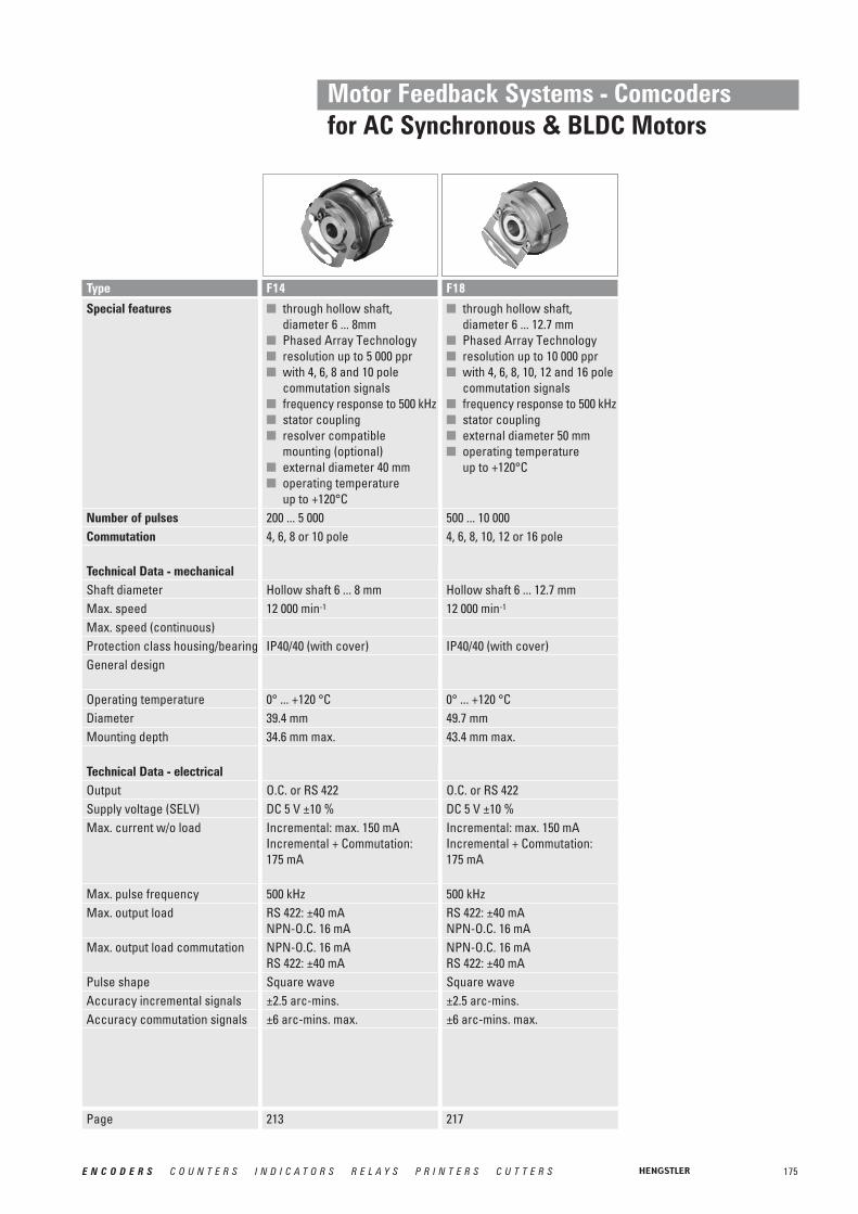
175E N C O D E R S C O U N T E R S I N D I C A T O R S R E L A Y S P R I N T E R S C U T T E R S
Motor Feedback Systems - Comcodersfor AC Synchronous & BLDC Motors
Special features
Number of pulsesCommutation
Technical Data - mechanicalShaft diameterMax. speedMax. speed (continuous)Protection class housing/bearingGeneral design
Operating temperatureDiameterMounting depth
Technical Data - electricalOutputSupply voltage (SELV)Max. current w/o load
Max. pulse frequencyMax. output load
Max. output load commutation
Pulse shapeAccuracy incremental signalsAccuracy commutation signals
Type
Page 217
■ through hollow shaft,diameter 6 ... 12.7 mm
■ Phased Array Technology■ resolution up to 10 000 ppr■ with 4, 6, 8, 10, 12 and 16 pole
commutation signals■ frequency response to 500 kHz■ stator coupling■ external diameter 50 mm■ operating temperature
up to +120°C
500 ... 10 0004, 6, 8, 10, 12 or 16 pole
Hollow shaft 6 ... 12.7 mm12 000 min-1
IP40/40 (with cover)
0° ... +120 °C49.7 mm43.4 mm max.
O.C. or RS 422DC 5 V ±10 %Incremental: max. 150 mA Incremental + Commutation: 175 mA
500 kHzRS 422: ±40 mANPN-O.C. 16 mANPN-O.C. 16 mARS 422: ±40 mASquare wave±2.5 arc-mins.±6 arc-mins. max.
F18
■ through hollow shaft,diameter 6 ... 8mm
■ Phased Array Technology■ resolution up to 5 000 ppr■ with 4, 6, 8 and 10 pole
commutation signals■ frequency response to 500 kHz■ stator coupling■ resolver compatible
mounting (optional)■ external diameter 40 mm■ operating temperature
up to +120°C200 ... 5 0004, 6, 8 or 10 pole
Hollow shaft 6 ... 8 mm12 000 min-1
IP40/40 (with cover)
0° ... +120 °C39.4 mm34.6 mm max.
O.C. or RS 422DC 5 V ±10 %Incremental: max. 150 mA Incremental + Commutation: 175 mA
500 kHzRS 422: ±40 mANPN-O.C. 16 mANPN-O.C. 16 mARS 422: ±40 mASquare wave±2.5 arc-mins.±6 arc-mins. max.
F14
213

176 E N C O D E R S C O U N T E R S I N D I C A T O R S R E L A Y S P R I N T E R S C U T T E R S
Motor Feedback Systems - Comcodersfor AC Synchronous & BLDC Motors
Special features
Number of pulsesCommutation
Technical Data - mechanicalHousing diameterShaftFlangeProtection class housing/bearingShaft load axial/ radialAxial runout of mating shaftRadial runout of mating shaftMax. speed
Max. operating temperature Vibration resistanceShock resistanceMaterial shaft / housing Weight Connection
Technical Data - electricalOutputSupply voltageMax. current w/o load Code
Tolerance Incremental signals
Tolerance CommutationOutput frequency Output circuit
Type
Page
■ Solid shaft motor encoder for BLDC and gearless elevator traction machines
■ Incremental & Commutation■ up to 10 000 ppr■ up to +120 °C operating
temperature■ IP54■ Housing diameter 53 mm500 ... 10 0004, 6, 8, 10, 12,16, 20, 24 or 32 pole
(preliminary)53 mmcone solid shaftspring tetherIP5420 / 90 N±1.4 mm±0.18 mm12 000 U/min (short term)5 000 U/min (continuous)-20°C … +120°C1000 m/s²25 m/s²Stainless steel / Aluminium200 gSub-D connectorPCB-connector with matingconnector and cable
(preliminary)O.C-NPN. or RS 422DC 5 ±10%100 mAIncremental with commutationoption, optical±2,5 arc-mins. max. (edge to edge)±6 arc-mins. max.max. 100 kHzDifferential line driver (ET7272),40 mA max.Open Collector, max. 8 mA; Pullup mit 2,0 kOhm
RF53
221

177E N C O D E R S C O U N T E R S I N D I C A T O R S R E L A Y S P R I N T E R S C U T T E R S
Motor Feedback Systems - Absolute Encodersfor AC Synchronous & BLDC Motors
Technical Data - mechanicalHousing diameterShaft diameterProtection class shaft inputProtection class housingFlange
Max. speed
Shaft loadTorqueSpring tether (hollow shaft)Tolerance axial / radialShock resistance (IEC 68-2-27)Vibration resistance (IEC 68-2-6)Operating temperatureWeight approx. ST/MT
Technical Data - electricalSupply voltage
Max. current w/o load ST/MTInterfaceLines/ DrivesOutput codeResolution singleturnResolution multiturnOptional incremental signals
Number of pulses3 db limiting frequencyAbsolute accuracyRepeatability
Alarm output
Connection
58 mmCone 10 mmIP40 IP40 Hollow shaft with tether,tapered shaftContinuous 10 000 min-1,Short term 12 000 min-1
0.01 Nm3.8 x 10-6 kgm2
± 1.5 mm/ ±0.2 mm1 000 m/s2 (6 ms)100 m/s2 (10 ... 2 000 Hz)
-15… +120 °C216 g / 310 g
DC 5 V, -5 % / + 10 %
50 mA / 100 mABiSS or Standard SSIClock and Data / RS422Binary or Gray13 Bit (SSI) - max. 22 Bit (BiSS)12 BitSine - Cosine 1 Vpp2048500 kHz
±35“±7“alarm bit (SSI), warning bit and alarm bit (BiSS)CablePCB-Connector 12 pole
110 mm up to 50 mm IP50 or IP64IP50 or IP64Hollow shaft with tether
IP50: 3600 min-1
IP64: 1500 min-1
± 0.5 mm / ± 0.05 mm1000 m/ s2 (6 ms) 100 m/ s2 (10 - 500 Hz)-20 ...+70°C 1000 g
DC 5 V (–5 %/ +10 %) or DC 10-30 V120 mA
Clock and Data/ RS422Binary or Gray10 - 17 Bitonly singleturnSine - Cosine 1 Vpp4096500 kHz± 35“± 7“alarm bit (SSI), warning bit and alarm bit (BiSS)Cable radialCable with Conin-Coupling
Type AD 58 AC 110
Page 228225
37.5mm8 mmIP40 IP40 Hollow shaft with tether
Continuous 10 000 min-1,Short term 12 000 min-1
0.01 Nm2.5 x 10-6 kgm2
± 0.5 mm/ ±0.05 mm1 000 m/s2 (6 ms)100 m/s2 (10 ... 2 000 Hz)
-25 … +100 °C80 g / 130 g
DC 5 V (–5 %/ +10 %) or DC 7-30 V50 mA / 100 mABiSS or Standard SSIClock and Data / RS422Binary or Gray12 - 17 Bit (SSI), 12 - 19 Bit (BiSS)12 BitSine - Cosine 1 Vpp2048500 kHz
±35“±7“Alarm bit (SSI), warning bit and alarm bit (BiSS)CablePCB-Connector 12 pole
AD 36
151

178 E N C O D E R S C O U N T E R S I N D I C A T O R S R E L A Y S P R I N T E R S C U T T E R S
Motor Feedback Systems - Sine-wave Encodersfor AC Synchronous & BLDC Motors
Special features
Technical Data - mechanicalShaft formShaft variations
Shaft diameterAbsolute max. shaft loadradial / axialBalance tolerancesMax. speedTorqueProtection class (EN 60529)General designOperating temperatureVibration resistance (IEC 68-2-6)Shock resistance (IEC 68-2-27)Material housingConnectionSizeWeight approx.
Technical Data - electricalSupply voltage (SELV)Max. current w/o loadIncremental signals A, B
Number of pulsesAbsolute accuracyRepeatability
Max. output frequencyReference signal: RCommutation signal: C, D
Type
Page 231
■ operating temperature rangeof -15 up to +120 °C
■ 500 kHz limiting frequencywith excellent signal quality
■ excellent immunity tointerference (EN 61000-4-4,Class 4)
■ signal control and systemmonitoring
■ high signal qualitythrough control and errorcompensation
Cone 1/10Tapered solid shaft(Tapered hollow shaft on request)10 mmwith tapered solid shaft: 90 N / 20 Naxial ± 0.5 mm, radial ± 0.1 mm12.000 min -1
≤ 1 NcmIP40as per DIN EN 61010-1-15 ... +120 °C≤ 100 m/s2
≤ 1000 m/s2
AluminiumPCB connector + cableØ 53.5 mm170 g
DC 5 V ±10 %max. 120 mASine - Cosine 1 Vpp2048±35“±7“500 kHz> 0.4 V (1pulse / turn)Sine - Cosine 1 Vpp (1 period / turn)
S21

179E N C O D E R S C O U N T E R S I N D I C A T O R S R E L A Y S P R I N T E R S C U T T E R S
Motor Feedback Systems - Resolverfor AC Synchronous & BLDC Motors
Special features
Number of pulsesCommutation
Technical Data - mechanicalShaft diameterMax. speedMax. speed (continuous)Protection class housing/bearingGeneral design
Operating temperatureDiameterMounting depth
Technical Data - electricalOutputSupply voltage (SELV)Max. current w/o load
Max. pulse frequencyMax. output load
Max. output load commutation
Pulse shapeToleranceAccuracy commutation signals
Type
Page 234
■ Through hollow shaft,diameter 4 up to 92 mm
■ compact design■ easy and quick mounting
procedure (standardizedresolver mounting)
■ Operating temperatureup to 155 °C
■ Applications, e.g. motors,maschine tools, robots,automated SMD equipment,medical technology
Drive or external electronicsDrive or external electronics
Hollow shaft 4.0 .. 92.7 mm20 000 min-1 (special: >30 000 min-1)
---
-25 ... +155 °CØ 26.5 ... 139.7 mm16.5 ... 31.8 mm
depends on input signal
Sinetypical +/- 10°---
Resolvers

180 E N C O D E R S C O U N T E R S I N D I C A T O R S R E L A Y S P R I N T E R S C U T T E R S
Motor Feedback Systemsfor Miniature DC and Stepper Motors
Type E 9
■ Ideal for position and speed sensing in small machines and actuators■ Low power standby mode is ideal for battery powered devices■ Operating frequency to 200 kHz■ Resolution to 512 lines/rev
GENERAL INFORMATION The type E9 incremental optical encoder provides high performance feedback for precision motion control in a very small package. Its small envelope makes it ideal forinstrument axes for position and speed control in mechanisms too small to accept standardencoders. Its high performance, advanced features, and competitive pricing make it theencoder of choice for a broad range of applications.
The E9 optical encoders utilize a patentpending ASIC that integrates all encoder electronics,including the optoelectronic sensors, which enhances reliability and accuracy.
Outputs are quadrature A and B channels with up to 512 lines per rev, an index pulse, unique up/down and rotation direction signals (version 2) or complementary CMOS-compatible (version 1). The E9 also has a low-power standby mode to conserve power in battery-operated applications.
Weight 5.07 gMoment of inertia 0.20 gcm2
Hollow shaft diameter 1.5 / 2.0 / 2.5 / 3.0 / 4.0 mm1.125‘’ / 0.156"
Hollow shaft tolerance + 0.010 / - 0.000 mmMating shaft length max. 12.16 mm
min. 11.36 mmMating shaft runout ± 0.0125 mmMating shaft endplay >256 ppr ±0.076mm;
250, 256 ppr +0.127 / -0.076mm;<250 ppr +0.178/ -0.076mm
Operating temperature -40 ... + 100 °CStorage temperature -50 ... + 125 °CRelative humidity 90 %, non-condensing
TECHNICAL DATAmechanical
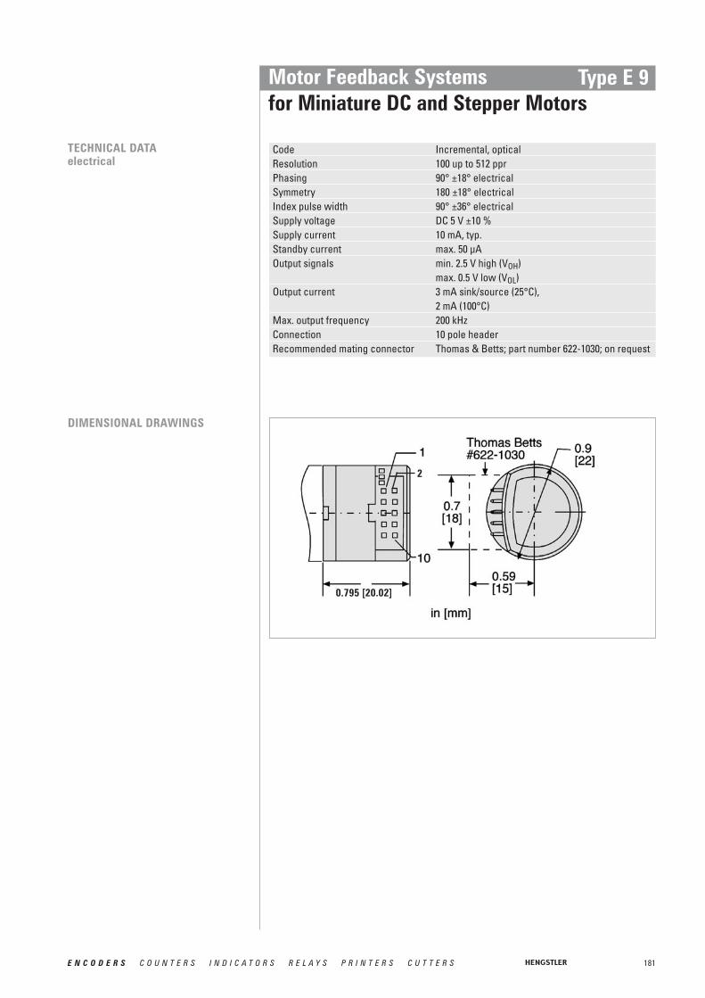
181E N C O D E R S C O U N T E R S I N D I C A T O R S R E L A Y S P R I N T E R S C U T T E R S
Motor Feedback Systemsfor Miniature DC and Stepper Motors
Type E 9
TECHNICAL DATAelectrical
Code Incremental, opticalResolution 100 up to 512 pprPhasing 90° ±18° electricalSymmetry 180 ±18° electricalIndex pulse width 90° ±36° electricalSupply voltage DC 5 V ±10 %Supply current 10 mA, typ.Standby current max. 50 μAOutput signals min. 2.5 V high (VOH)
max. 0.5 V low (VOL)Output current 3 mA sink/source (25°C),
2 mA (100°C)Max. output frequency 200 kHzConnection 10 pole header Recommended mating connector Thomas & Betts; part number 622-1030; on request
DIMENSIONAL DRAWINGS
2
0.795 [20.02]

OUTPUT WAVEFORMS AND CONNECTIONS(Direction viewing encoder cover)
182 E N C O D E R S C O U N T E R S I N D I C A T O R S R E L A Y S P R I N T E R S C U T T E R S
Motor Feedback Systemsfor Miniature DC and Stepper Motors
Type E 9
Figure 1 Figure 2 Figure 3
Code 00 for odering information Code 01 for odering information Code 02 for odering information
Important: To properly install type E9, a specialized mounting kit must be purchased. Only one kit is required to install any number of encoders with the same hub shaft size.
E 9MKHub shaft1.5 1.5 mm2.0 2.0 mm2.5 2.5 mm3.0 3.0 mm125 0.125 inch156 0.156 inch
Example: Kit for installing encoders with 3.0 mm hub shaft = MK E9 3.0
Please designate hub shaft diameter.
ORDERING INFORMATION
Hub shaftPulses pprType
1.5 1.5 mm2.0 2.0 mm2.5 2.5 mm3.0 3.0 mm125 0.125 inch156 0.156 inch
0 100 0 3000 144 0 3600 200 0 5000 256 0 512
E9-
Output Mounting
00 see fig. 101 see fig. 202 see fig. 3
0 No mounting baseA 4 x M1.6 on 0.728’’ TKC 2 x #2-56 on 0.75’’ TKD 3 x #0-80 on 0.823’’ TKE 2 x #2-56 on 1.812’’ TK
CH NCH N-
CH N
ACCESSORIES Ordering code10 pole header, 30 cm ribbon cable with connector CA 0 040 012

183E N C O D E R S C O U N T E R S I N D I C A T O R S R E L A Y S P R I N T E R S C U T T E R S
Motor Feedback Systemsfor Miniature DC and Stepper Motors
Type M 9
■ Ideal for position and speed sensing in small machines and actuators■ 200 kHz operating frequency■ Resolution to 512 lines/rev
GENERAL INFORMATION With a total length less than 15mm and a very low mass, the type M9 incremental opticalencoder is ideally suited for use on the moving heads of pick-and-place type machines.
The M9 may be used as direct replacements for most Hewlett Packard HEDS-5XXX encoderswith no changes to the motor or cable.
The M9 provides high performance feedback for precision motion control in a very smallpackage. Its small envelope makes it ideal for instrument axes for position and speed control in mechanisms too small to accept standard encoders.
Its high performance, advanced features, and competitive pricing make it the encoder ofchoice for a broad range of applications.
It utilizes an ASIC that integates all encoder electronics, including the optoelectronics sensors, which enhances reliability and accuracy.
Outputs are single-ended quadrature A and B channels with up to 512 lines per rev plus anindex pulse.
Weight 4.14 gMoment of inertia 0.11 gcm2
Hollow shaft diameter 1.5 / 2.0 / 2.5 / 3.0 / 4.0 mm1.125‘’ / 0.156"
Hollow shaft tolerance + 0.010 / - 0.000 mmMating shaft length max. 11.1 mm
min. 9.75 mmMating shaft runout ± 0.0125 mmMating shaft endplay 256 ppr ±0.076 mm;
250 / 256 ppr + 0.127 / - 0.076 mm;< 250 ppr + 0.178 / - 0.076 mm
Operating temperature -40 ... + 100 °CStorage temperature -50 ... + 125 °CRelative humidity 90 %, non-condensing
TECHNICAL DATAmechanical
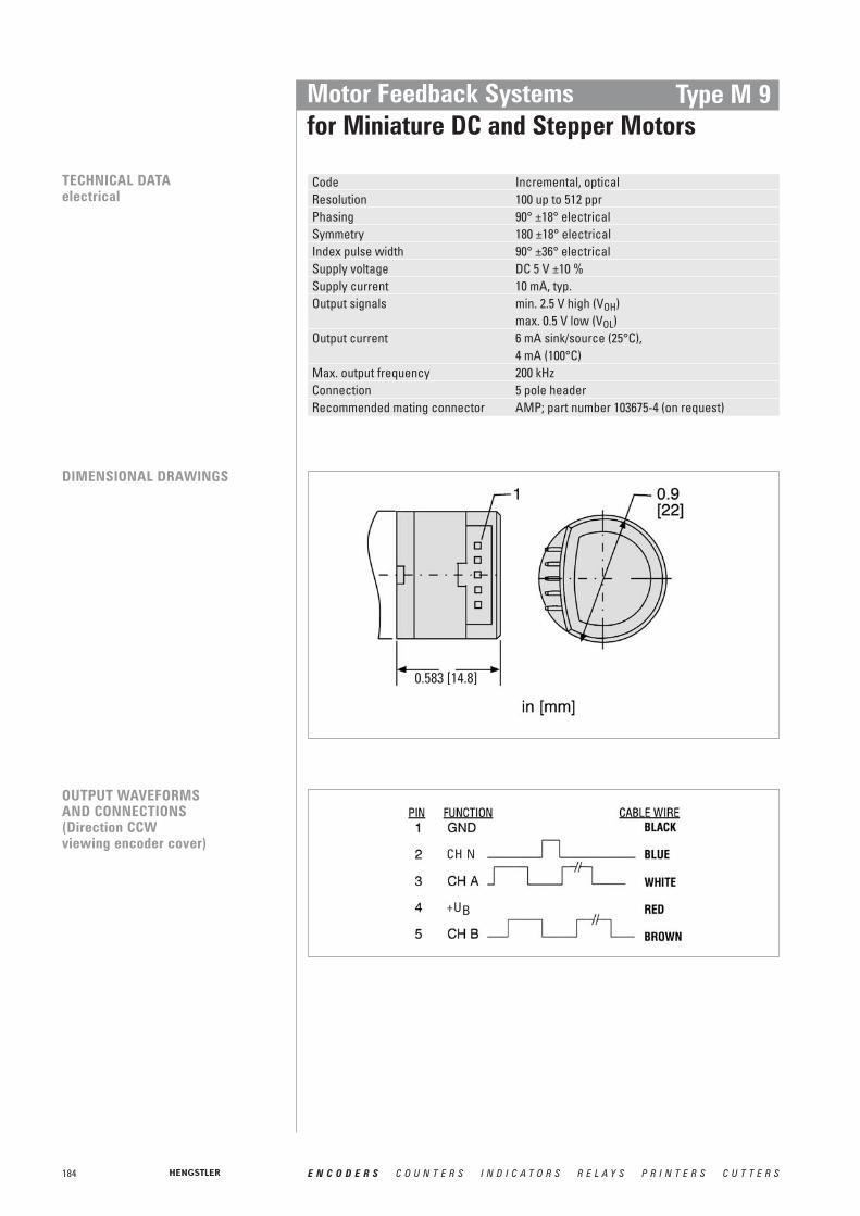
184 E N C O D E R S C O U N T E R S I N D I C A T O R S R E L A Y S P R I N T E R S C U T T E R S
Motor Feedback Systemsfor Miniature DC and Stepper Motors
Type M 9
TECHNICAL DATAelectrical
Code Incremental, opticalResolution 100 up to 512 pprPhasing 90° ±18° electricalSymmetry 180 ±18° electricalIndex pulse width 90° ±36° electricalSupply voltage DC 5 V ±10 %Supply current 10 mA, typ.Output signals min. 2.5 V high (VOH)
max. 0.5 V low (VOL)Output current 6 mA sink/source (25°C),
4 mA (100°C)Max. output frequency 200 kHzConnection 5 pole header Recommended mating connector AMP; part number 103675-4 (on request)
DIMENSIONAL DRAWINGS
OUTPUT WAVEFORMS AND CONNECTIONS (Direction CCW viewing encoder cover)
0.583 [14.8]
CH N
+UB

185E N C O D E R S C O U N T E R S I N D I C A T O R S R E L A Y S P R I N T E R S C U T T E R S
Motor Feedback Systemsfor Miniature DC and Stepper Motors
Important: To properly install type M9, a specialized mounting kit must be purchased. Only one kit is required to install any number of encoders with the same hub shaft size.
M 9MKHub shaft1.5 1.5 mm2.0 2.0 mm2.5 2.5 mm3.0 3.0 mm125 0.125 inch156 0.156 inch
Example: Kit for installing encoders with 3.0 mm hub shaft = MK M9 3.0
Please designate hub shaft diameter.
ORDERING INFORMATION
Hub shaftPulses ppr /polesType
1.5 1.5 mm2.0 2.0 mm2.5 2.5 mm3.0 3.0 mm4.0 4.0 mm125 0.125 inch156 0.156 inch
0100 / 00144 / 00200 / 00256 / 00300 / 00360 / 00500 / 00512 / 0
M9-
OutputMounting
1 5 pin header2 flying leads
0 No mounting baseA 4 x M1.6 on 18.5mm TKC 2 x #2-56 on 19.05 mm TKD 3 x #0-80 on 20.9 mm TKE 2 x #2-56 on 46.02 mm TK
Type M 9
ACCESSORIES Ordering code5 pole header, 30 cm ribbon cable with connector CA 0 050 012

186 E N C O D E R S C O U N T E R S I N D I C A T O R S R E L A Y S P R I N T E R S C U T T E R S
Motor Feedback Systemsfor Miniature DC and Stepper Motors
Type M 14
■ Ideal economical feedback device for servo and step motors■ Short axial length and compact 1.5 inch diameter■ Easy "snap-on" installation■ High resolution to 1024 lines/rev and 200 kHz bandwidth■ Drop-in replacement for HP 5540■ CE-qualified
GENERAL INFORMATION The type M14 of incremental optical encoders provides high performance feedback for precision motion control in a small, low cost package.
Its high performance, advanced features, and competitive pricing make it the encoder ofchoice for a broad range of applications.
The M14 optical encoder utilizes a patentpending ASIC that integrates all encoder electronics, including the optoelectronic sensors, which enhances reliability and accu-racy.
Quadrature A and B channels with up to 1024 lines per revolution and reference pulse areoutput as single-ended TTL/CMOS compatible signals.
The M 14 can be used as drop-in replacement for HP 5540.
Weight 6.2 gMoment of inertia 0.13 gcm2
Hollow shaft diameter 3.0 bis 8.0 mmHollow shaft tolerance +0.010 mm / -0.000 mmMating shaft length max. 13.3 mm;
min. 11.07 mmMating shaft runout ± 0.0125 mmMating shaft endplay >512 ppr ±0.076 mm;
500 / 512 ppr ±0.127 / - 0.076 mm;< 500 ppr + 0.178 / - 0.076 mm
Operating temperature -40 °C ... 100 °CStorage temperature -50 °C ... 125 °CRelative humidity 90 % non-condensing
TECHNICAL DATAmechanical

187E N C O D E R S C O U N T E R S I N D I C A T O R S R E L A Y S P R I N T E R S C U T T E R S
Motor Feedback Systemsfor Miniature DC and Stepper Motors
Type M 14
TECHNICAL DATAelectrical
Code Incremental, opticalResolution 200 up to 1 024 pprPhasing 90° ±18° electricalSymmetry 180 ±18° electricalIndex pulse width 90° ±36° electricalSupply voltage DC 5 V ±10 %Supply current 10 mA, typ.Output signals min. DC 2.5 V high (VOH)
max. DC 0.5 V low (VOL)Output current 6mA sink/source (25°C)
4 mA (100°C)Max. output frequency 200 kHzConnection 5 pole header Recommended mating connector AMP, part number. 103969-4 (on request)
DIMENSIONAL DRAWING
OUTPUT WAVEFORMS & CONNECTIONS(Direction viewing encoder cover)
CH N
+UB

188 E N C O D E R S C O U N T E R S I N D I C A T O R S R E L A Y S P R I N T E R S C U T T E R S
Motor Feedback Systemsfor Miniature DC and Stepper Motors
Type M 14
Important: To properly install type M14, a specialized mounting kit must be purchased. Only one kit is required to install any number of encoders with the same hub shaft size.
M 1 4MK
Example: Kit for installing encoders with 0.1248’’ mm hub shaft = MK M14 125
Please designatehub shaft diameter.
Hub shaft3.0 3 mm 187 0.1873 inch4.0 4 mm 249 0.2498 inch5.0 5 mm 250 0.2501 inch6.0 6 mm 312 0.3123 inch8.0 8 mm 374 0.3748 inch125 0.1248 inch 375 0.3750 inch
ORDERING INFORMATION
MountingPulses ppr /polesType
0 No mounting baseA 2 x #2-56 on 1.28’’ TKB 3 x #0-80 on 0.823’’ TKC 2 x #2-56 on 0.75’’ TK
0 200 / 00 400 / 00 500 / 00 512 / 01 000 / 01 024 / 0
M14-
Hub shaft
3.0 3 mm 187 0.1873 inch4.0 4 mm 249 0.2498 inch5.0 5 mm 250 0.2501 inch6.0 6 mm 312 0.3123 inch8.0 8 mm 374 0.3748 inch125 0.1248 inch 375 0.3750 inch
ACCESSORIES Ordering code5 pole header, 30 cm ribbon cable with connector CA 0 060 012

189E N C O D E R S C O U N T E R S I N D I C A T O R S R E L A Y S P R I N T E R S C U T T E R S
Motor Feedback Systems - Hollow shaft Encodersfor Asynchronous & DC Motors Incremental
HOLLOW SHAFT ENCODER RI36-H
■ Miniature industry encoder for high numbers of pulses (5 .. 3600)■ Hollow shaft (up to 10mm)■ Short overall length■ Easy and quick mounting procedure
There are two different spring tethers availbale.
Detailed description: Page 62
HOLLOW SHAFT ENCODERS RI58-D, TD, -G, TG
■ Flexible hollow shaft design up to diameter 14 mm (-D,TD), 15mm hollow shaft (-G,TG)■ Short overall length■ Easy installation by means of clamping ring or blind shaft■ Operating temperature up to 100°C (RI58 TD and TG)■ High number of pulses (5 .. 5000) with -D■ Limited number of pulses (4 .. 2500) with TD and (50 .. 2500) with TG
The RI58 hollow shaft family offers a broad spectrum of mounting possibilities andis the right choice for all drive systems because of its high temperature option.
Detailed description of RI58-D, TD: Page 68Detailed information of RI58-G, TG on request
HOLLOW SHAFT ENCODER RI76TD
■ Through hollow shaft with up to diameter 42 mm■ Short overall length with an outside diameter of only 76 mm■ Easy installation by means of clamping ring■ Operating temperature up to 100 °C
Different Mounting options are available.
Detailed description: Page 72
Our hollow shaft encoder industry types are particularly suitable as a motor feedback product for asynchronous- and DC motors. Due to the partially higher requirements on theoperating temperature, there are specially developed high temperature versions (-TD) available, among certain types.
OVERWIEW
HOLLOW SHAFT ENCODER RI80-E
■ Incremental Output■ 30...45 mm hollow shaft ■ Rugged mechanical design■ Unbreakable disc■ Integrated diagnostic system■ Wide voltage range DC 5 … 30 V
The RI80-E is the first encoder using the latest Hengstler OptoAsic technology.
Detailed description: Page 78
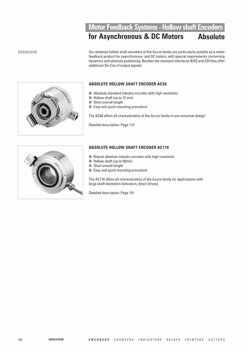
190 E N C O D E R S C O U N T E R S I N D I C A T O R S R E L A Y S P R I N T E R S C U T T E R S
Motor Feedback Systems - Hollow shaft Encodersfor Asynchronous & DC Motors Absolute
ABSOLUTE HOLLOW SHAFT ENCODER AC58
■ Absolute standard industry encoder with high resolution■ Hollow shaft (up to 12 mm)■ Short overall length■ Easy and quick mounting procedure
The AC58 offers all characteristics of the Acuro family in one universal design.
Detailed description: Page 113
ABSOLUTE HOLLOW SHAFT ENCODER AC110
■ Robust absolute industry encoder with high resolution■ Hollow shaft (up to 50mm)■ Short overall length■ Easy and quick mounting procedure
The AC110 offers all characteristics of the Acuro family for applications with large shaft diameters (elevators, direct drives).
Detailed description: Page 151
Our absolute hollow shaft encoders of the Acuro family are particularly suitable as a motorfeedback product for asynchronous- and DC motors, with special requirements concerningdynamics and absolute positioning. Besides the standard interfaces BiSS and SSI they offeradditional Sin Cos of output signals.
OVERVIEW

191E N C O D E R S C O U N T E R S I N D I C A T O R S R E L A Y S P R I N T E R S C U T T E R S
Weight 23 g without cover, 28 g with coverDimensions
Outside diameter 39.6 mm with cover, 37.1 mm without coverDepth 27.9 mm with cover 1 , 24.1 mm without cover
Hub shaft diameters 6 mm / 8 mm / 10 mm / 3.18 mm (1 ⁄ 8”) / 4.76 mm (3 ⁄ 16”) / 6.35 mm (1 ⁄ 4”) /9.52 mm (3 ⁄ 8”)
Hollow shaft tolerance +0.026 mm ... -0.000 mmMating shaft length min. 12 mm
max. 22 mm with closed coverShaft misalignment axial endplay 2 : +0.38 mm ... -0.38 mm
radial runout: 0.05 mm (incl. angular misalignment)Alignment of encoder channels coarse alignment: index mark on hubto motor windings fine alignment: ±15° mechanical alignment rangeMax. speed 12 000 min-1
Moment of inertia 4.7 gcm2
Protection class (EN 60529) IP40 4 (version cable)IP30 4 (version dual row connector)
Operating temperature -40 ... +120 °CStorage temperature -40 ... +85 °CVibration resistance (IEC 68-2-6) 25 m/s2 (5 ... 2 000 Hz)Shock resistance (IEC 68-2-27) 500 m/s2 (11 ms)Connection shieded cable radial or dual row connector 3
Housing glassfibre reinforced plastic
TECHNICAL DATAmechanical
1 for radial cable connection2 + means away from mounting face3 10 pins for version incremental only, 14 pins for version incremental+commutation4 mounted and with cover
■ Incremental + commutation■ Practically no speed limitation, since up to 12 000 RPM ■ Very good dynamic behaviour through low moment of inertia of rotor and its minimal
influence on the motor■ Very good drive stiffness since no coupling is used■ Compact size■ Excellent price-performance ratio■ Increased temperature range, -40 to + 120°C■ Incomparable shaft play tolerances (to 0.7 mm axial)■ Better frequency, 200 KHz■ Flexibility, since the user can integrate in all actual motor sizes■ Simple mounting and adjustment since encoders come aligned and gapped
Motor Feedback Systemsfor AC Synchronous & BLDC Motors
Type M 15
NUMBER OF PULSES 200, 400, 500, 1000, 1024; optional 4, 6 or 8 pole commutation signals
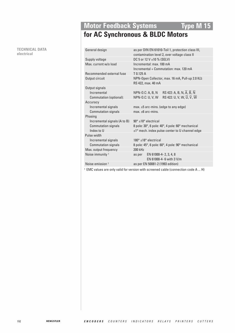
192 E N C O D E R S C O U N T E R S I N D I C A T O R S R E L A Y S P R I N T E R S C U T T E R S
General design as per DIN EN 61010-Teil 1, protection class III,contamination level 2, over voltage class II
Supply voltage DC 5 or 12 V ±10 % (SELV)Max. current w/o load Incremental: max. 100 mA
Incremental + Commutation: max. 120 mARecommended external fuse T 0.125 AOutput circuit NPN-Open Collector, max. 16 mA, Pull-up 2.0 KΩ
RS 422, max. 40 mAOutput signals
Incremental NPN-O.C: A, B, N RS 422: A, B, N, , , Commutation (optional): NPN-O.C: U, V, W RS 422: U, V, W, , ,
AccuracyIncremental signals max. ±5 arc-mins. (edge to any edge)Commutation signals max. ±6 arc-mins.
PhasingIncremental signals (A to B) 90° ±18° electricalCommutation signals 8 pole: 30°, 6 pole: 40°, 4 pole: 60° mechanicalIndex to U ±1° mech. index pulse center to U channel edge
Pulse widthIncremental signals 180° ±18° electricalCommutation signals 8 pole: 45°, 6 pole: 60°, 4 pole: 90° mechanical
Max. output frequency 200 kHzNoise immunity 1 as per EN 61000-4- 2, 3, 4, 8
EN 61000-4- 6 with 3 V/mNoise emission 1 as per EN 50081-2 (1993 edition)
WVUNBA
Motor Feedback Systemsfor AC Synchronous & BLDC Motors
Type M 15
TECHNICAL DATAelectrical
1 EMC values are only valid for version with screened cable (connection code A ... H)
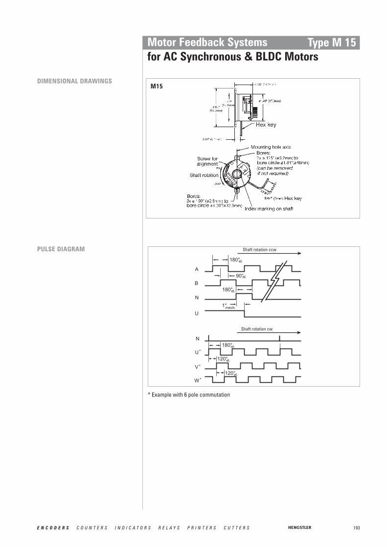
193E N C O D E R S C O U N T E R S I N D I C A T O R S R E L A Y S P R I N T E R S C U T T E R S
Motor Feedback Systemsfor AC Synchronous & BLDC Motors
Type M 15
DIMENSIONAL DRAWINGSM15
* Example with 6 pole commutation
PULSE DIAGRAM Shaft rotation ccw
Shaft rotation cw

194 E N C O D E R S C O U N T E R S I N D I C A T O R S R E L A Y S P R I N T E R S C U T T E R S
Motor Feedback Systemsfor AC Synchronous & BLDC Motors
Type M 15
Function Colour for version Colour for versionincremental only, incremental + commutation,Code Electrical = 0, 1, 3 Code Electrical = 6, 7, 9
VCCcom 1 red/white 3
VCCinc 1 red redGND inc black blackGND com black/white 3
2 red/black blue/blackA green blue
2 white/black green/blackB orange green
2 blue violet/blackN white violet
2 brown/blackU brown
2 grey/blackV grey
2 white/blackW whiteW
V
U
N
B
A
CONNECTION DIAGRAM CABLE
1 VCCcom resp. VCCinc = + DC 5 V or + DC 12 V (see ordering data electrical)2 only with Output inc/com= RS 4223 not connected for code 6 and 9, as here Uinc = Ucom
Pin 10 pole 10 pole 14 poleonly incr., NPN-O.C., only incr., RS422, incr.+commutation,Code Electr.= 0, 1 Code Electr.= 3 Code Electr.= 6, 7, 9
1 A VCC
2 VCC VCC U3 GND GND4 V56 A W78 B B9 A
10 N N B1112 N13 GND14 N
B
NAWB
VA
U
Pin Numbering:For dual row connector with ribbon cable:The cable side marked red designates pin 1
CONNECTION DIAGRAM DUAL ROW CONNECTOR

195E N C O D E R S C O U N T E R S I N D I C A T O R S R E L A Y S P R I N T E R S C U T T E R S
Motor Feedback Systemsfor AC Synchronous & BLDC Motors
Type M 15
Available combinations (pulses/poles)
1 Uinc: Supply voltage incremental,Ucom: Supply voltage commutation (only if commutation selected)
2 allowed combinations see available combinations (pulses/poles)
ORDERING INFORMATION
HousingPulses pprincremental 2Type
0 without cover1 closed cover
for blind shaft2 cover with
bore for through shaft
0 2000 4000 5001 0001 024
M15-
Polescommutation 2
0 without4 4 pole6 6 pole8 8 pole
-/
Electrical 1
incremental onlywithout commutation0 Uinc=DC 5 V;
outputinc=NPN-O.C.1 Uinc=DC 12 V;
outputinc=NPN-O.C.3 Uinc=DC 5 V;
outputinc=RS 422incremental plus commutation signals6 Uinc=DC 5 V;
outputinc=RS 422,Ucom=DC 5 V; outputcom=NPN-O.C.
7 Uinc=DC 5 V;outputinc=RS 422,Ucom=DC 12 V; outputcom=NPN-O.C.
9 Uinc=DC 5 V; outputinc=RS 422,Ucom=DC 5 V; outputcom=RS 422
Hubdiameter 2 Connection
0 6.35 mm (1 ⁄ 4 ”)1 9.52 mm (3 ⁄ 8 ”)4 6 mm5 8 mm6 10 mm8 4.76 mm (3 ⁄ 16 ”)9 3.18 mm (1 ⁄ 8 ”)
0 dual row connector1...8 dual row connector
with mating ribbon cable1=30 cm, 2=60 cm, ...
A...H screened cableradial, A=30 cm,
B=60 cm, ...
Number of polesPulses ppr 0 4 6 80200 X0400 X0500 X X X X1000 X X X X1024 X X X X
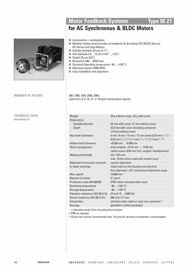
196 E N C O D E R S C O U N T E R S I N D I C A T O R S R E L A Y S P R I N T E R S C U T T E R S
Motor Feedback Systemsfor AC Synchronous & BLDC Motors
Type M 21
■ Incremental + commutation■ Modular hollow shaft encoder as feedback for Brushless DC (BLDC) Servos,
DC Servos and Step Motors■ Outside diameter 53 mm (2.1“)■ Hub diameters 6 ... 12 mm (1¼4” ... 1¼2”)■ Height 20 mm (0,8”)■ Resolution 500 ... 2048 lines■ Standard Operating temperature -40 ... +120 °C■ Maximum speed 12000 RPM■ Easy installation and alignment
NUMBER OF PULSES 500, 1000, 1024, 2000, 2048; optional 4, 6, 8, 10, 12 or 16 pole commutation signals
Weight 28 g without cover, 43 g with coverDimensions
Outside diameter 53 mm with cover, 51 mm without coverDepth 20.3 mm with cover excluding connector
17.9 mm without coverHub shaft diameters 6 mm / 8 mm / 10 mm / 12 mm sowie 6.35 mm (1 ⁄ 4”) /
9.52 mm (3 ⁄ 8”) / 11.11 mm (7 ⁄ 16 ‘’) / 12.7 mm (1 ⁄ 2”)Hollow shaft tolerance +0.026 mm ... -0.000 mmShaft misalignment axial endplay: +0.13 mm 1 ... -0.38 mm
radial runout: 0.05 mm (incl. angular misalignment)Mating shaft length min. 16.5 mm
max. 19 mm when used with closed coverAlignment of encoder channels coarse alignment: to motor windings index mark on the housing and disc/hub
fine alignment: ±15° mechanical alignment rangeMax. speed 12 000 min -1
Moment of inertia 4.7 gcm2
Protection class (EN 60529) IP40 2 when mounted with coverOperating temperature -40 ... +120 °CStorage temperature -40 ... +120 °CVibration resistance (IEC 68-2-6) 25 m/s2 (5 ... 2 000 Hz)Shock resistance (IEC 68-2-27) 500 m/s2 (11 ms)Connection shieded cable radial or dual row connector 3
Housing glassfibre reinforced plastic
TECHNICAL DATAmechanical
1 + indicates away from mounting face (cover)2 IP50 on request 3 10 pins for version incremental only, 14 pins for version incremental +commutation
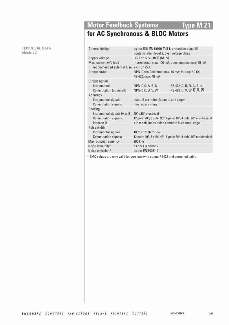
197E N C O D E R S C O U N T E R S I N D I C A T O R S R E L A Y S P R I N T E R S C U T T E R S
Motor Feedback Systemsfor AC Synchronous & BLDC Motors
Type M 21
TECHNICAL DATAelectrical
General design as per DIN EN 61010-Teil 1, protection class III,contamination level 2, over voltage class II
Supply voltage DC 5 or 12 V ±10 % (SELV)Max. current w/o load Incremental: max. 100 mA; commutation: max. 75 mA
recommended external fuse 2 x T 0.125 AOutput circuit NPN-Open Collector, max. 16 mA; Pull-up 2.0 KΩ
RS 422, max. 40 mAOutput signals
Incremental NPN-O.C: A, B, N RS 422: A, B, N, , , Commutation (optional): NPN-O.C: U, V, W RS 422: U, V, W, , ,
AccuracyIncremental signals max. ±5 arc-mins. (edge to any edge)Commutation signals max. ±6 arc-mins.
PhasingIncremental signals (A to B) 90° ±18° electricalCommutation signals 12 pole: 20°, 8 pole: 30°, 6 pole: 40°, 4 pole: 60° mechanicalIndex to U ±1° mech. index pulse center to U channel edge
Pulse widthIncremental signals 180° ±18° electricalCommutation signals 12 pole: 30°, 8 pole: 45°, 6 pole: 60°, 4 pole: 90° mechanical
Max. output frequency. 200 kHzNoise immunity 1 as per EN 50082-2Noise emission 1 as per EN 50081-2
WVUNBA
1 EMC values are only valid for versions with output RS422 and screened cable

198 E N C O D E R S C O U N T E R S I N D I C A T O R S R E L A Y S P R I N T E R S C U T T E R S
Motor Feedback Systemsfor AC Synchronous & BLDC Motors
Type M 21
DIMENSIONAL DRAWINGS
* Beispiel mit 6-poliger commutation
PULSE DIAGRAMShaft rotation ccw
Shaft rotation cw
Dimensions in mm (inch)

199E N C O D E R S C O U N T E R S I N D I C A T O R S R E L A Y S P R I N T E R S C U T T E R S
Motor Feedback Systemsfor AC Synchronous & BLDC Motors
Type M 21
Function 10 pole 10 pole 16 poleonly incr., NPN-O.C., only incr., RS422, incr.+commutation,Code Electr.= 0, 1 Code Electr.= 3 Code Electr.= 6, 7, 9
VCCcom 1 1VCCinc 1 2 2 2GND inc 3 3 3GND com 4
2 5 5A 1 1 6
2 7 7B 8 8 8
2 9 9N 10 10 10
2 11U 12
2 13V 14
2 15W 16W
V
U
N
B
A
Function Colour for version Colour for versionincremental only, incremental + commutation,Code Electrical = 3 Code Electrical = 6, 7, 9
VCCcom 1 red/white 3
VCCinc 1 red redGND inc black blackGND com black/white 3
red/black blue/blackA green blue
white/black green/blackB orange green
blue violet/blackN white violet
2 brown/blackU brown
2 grey/blackV grey
2 white/blackW whiteW
V
U
N
B
A
Pin Numbering:For dual row connector with ribbon cable:The cable side marked red designates Pin 1
CONNECTION DIAGRAM CABLE
1 VCC com resp. VCC inc = + DC 5 V or + DC 12 V (see ordering data electrical)2 only for output com= RS4223 not connected for codes 6 and 9, since here Uinc = Ucom
CONNECTION DIAGRAMCONNECTOR
1 VCCcom resp. VCCinc = + DC 5 V or + DC 12 V (see ordering data electrical)2 only for outputinc/com= RS422

200 E N C O D E R S C O U N T E R S I N D I C A T O R S R E L A Y S P R I N T E R S C U T T E R S
Motor Feedback Systemsfor AC Synchronous & BLDC Motors
Type M 21
1 Uinc: Supply voltage incremental,Ucom: Supply voltage commutation (only if commutation is selected)
2 Exposed hub clamp screw3 only possible with output = RS 422 (Code for Electrical ≥ 3)4 allowed combinations see available combinations (pulses/poles)
Available combinations (pulses/poles)
ORDERING INFORMATION
HousingPulses pprincremental 4Type
0 without cover1 closed cover
for blind shaft2 cover with
bore for through shaft
0 5000 5121 0001 0242 0002 048
M21-
Polescommutation 4
0 without4 4 pole6 6 pole8 8 poleA 10 poleC 12 poleX 16 pole
-/
Electrical 1
incremental onlywithout commutation0 Uinc=DC 5 V;
outputinc=NPN-O.C.1 Uinc=DC 12 V;
outputinc=NPN-O.C.3 Uinc=DC 5 V;
outputinc=RS 422incremental plus commutation signals6 Uinc=DC 5 V;
outputinc=RS 422,Ucom=DC 5 V; outputcom=NPN-O.C.
7 Uinc=DC 5 V; outputinc=RS 422,Ucom=DC 12 V; outputcom=NPN-O.C.
9 Uinc=DC 5 V; outputinc=RS 422,Ucom=DC 5 V; outputcom=RS 422
Hubdiameter 2 Connection
A 6.35 mm (1 ⁄ 4 ”)B 9.52 mm (3 ⁄ 8”)C 11.11 mm (7 ⁄ 16”)D 12.7 mm (1 ⁄ 2”)E 6 mmF 8 mmG 10 mmH 12 mm
0 dual row connector1...8 dual row connector
with mating ribbon cable1=30 cm, 2=60 cm, ...
A...H screened cable 3radial, A=30 cm, B=60 cm, ...
Number of polesPulses ppr 0 4 6 8 10 (=A) 12 (=C) 16 (=X)0500 X X X X X0512 X X1000 X X X X X1024 X X X X X2000 X X X X X2048 X X X X X X X

201E N C O D E R S C O U N T E R S I N D I C A T O R S R E L A Y S P R I N T E R S C U T T E R S
Motor Feedback Systemsfor AC Synchronous & BLDC Motors
Type F 10
■ Compact hollowshaft motor encoder, ideal for BLDC,DC-Servo and Stepper feedback
■ Resolver compatible mounting■ Resolution up to 2 048 ppr■ Operating temperature up to 120 °C ■ Frequency response to 300 kHz■ Mounting depth 22.4 mm
GENERAL INFORMATION The type F10 encoder provides high performance, cost effective feedback for stepper andservo motor applications. The F10 offers compact package dimensions and flying leads fora low-profile installation. A size 10 servo ring allows easy mounting and replacement ofpancake resolvers with high tolerance to motor shaft movement and 360 degrees of adjustment to align the signal outputs to the shaft position.
Weight approx. 45 gDimensions Outside diameter: 31.7 mm max.;
Hight: 24.1 mm max.Material Housing: cast-aluminium;
Servo ring: aluminium;Hub: brass; Disk: 0.76 mm thick glass
Moment of inertia 1.6 gcm2
Hollow shaft diameter 6 mmHollow shaft balance +0.001"/-0.000" (+0.025 mm/-0.000 mm)Radial runout of ±0.05 mm max. (includes shaft perpendicularitymating shaft to mounting surface)Axial endplay of ±0.25 mm max.mating shaftMounting 1.045" (26.54 mm) flexible servo ring
(size 10 pancake resolver equivalent)Acceleration 100 000 rad/s2 max.Max. speed 5 000 min-1 continuous;
12 000 min-1 peakBearing life [(3.6 x 10⁹) / RPM] hours;
e.g. 605 000 hours at 6 000 RPMOperating temperature 0° ... +120 °CStorage temperature 0° ... +120 °CShock resistance 50 g for 6 ms durationVibration resistance 2.5 g at 5 to 2 000 HzRelative humidity 90 % non-condensing
TECHNICAL DATAmechanical
NUMBER OF PULSES 1024, 2048; optional additional 6 or 10 pole commutation signals
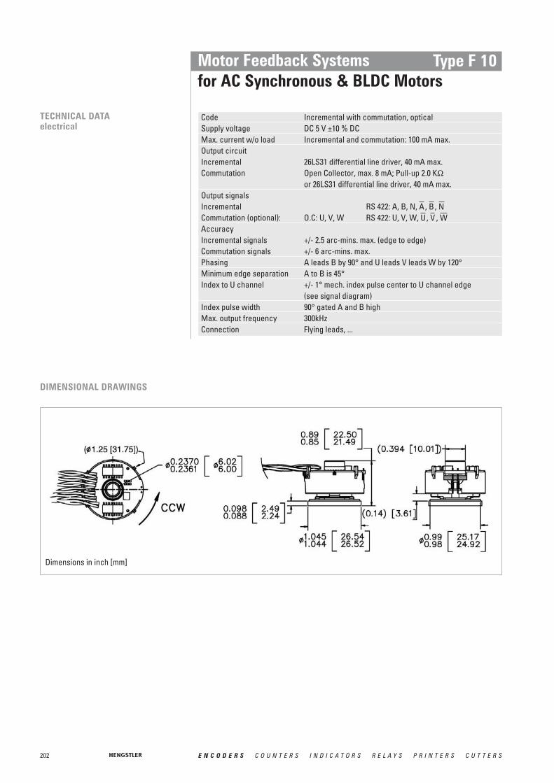
202 E N C O D E R S C O U N T E R S I N D I C A T O R S R E L A Y S P R I N T E R S C U T T E R S
Motor Feedback Systemsfor AC Synchronous & BLDC Motors
Type F 10
TECHNICAL DATAelectrical
Code Incremental with commutation, opticalSupply voltage DC 5 V ±10 % DCMax. current w/o load Incremental and commutation: 100 mA max.Output circuit Incremental 26LS31 differential line driver, 40 mA max.Commutation Open Collector, max. 8 mA; Pull-up 2.0 KΩ
or 26LS31 differential line driver, 40 mA max.Output signalsIncremental RS 422: A, B, N, , , Commutation (optional): O.C: U, V, W RS 422: U, V, W, , , AccuracyIncremental signals +/- 2.5 arc-mins. max. (edge to edge)Commutation signals +/- 6 arc-mins. max.Phasing A leads B by 90° and U leads V leads W by 120°Minimum edge separation A to B is 45°Index to U channel +/- 1° mech. index pulse center to U channel edge
(see signal diagram)Index pulse width 90° gated A and B highMax. output frequency 300kHzConnection Flying leads, ...
WVUNBA
DIMENSIONAL DRAWINGS
Dimensions in inch [mm]

203E N C O D E R S C O U N T E R S I N D I C A T O R S R E L A Y S P R I N T E R S C U T T E R S
Motor Feedback Systemsfor AC Synchronous & BLDC Motors
Type F 10
SIGNAL DIAGRAM
Waveforms below show relationship betweenCH, N, U, V & W (scale differs from above)
ccw shaft rotation
CONNECTION DIAGRAM Function 1 ColourVCC redGND black
blue/blackA blue
green/blackB green
violet/blackN violet
brown/blackU brown
grey/blackV grey
white/blackW whiteW
V
U
N
B
A
1 availability of function depends on version
N
N
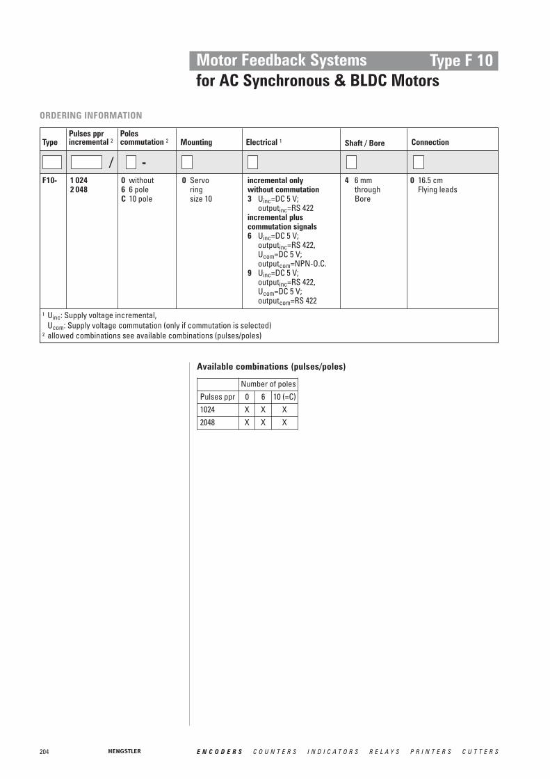
204 E N C O D E R S C O U N T E R S I N D I C A T O R S R E L A Y S P R I N T E R S C U T T E R S
Motor Feedback Systemsfor AC Synchronous & BLDC Motors
Type F 10
1 Uinc: Supply voltage incremental,Ucom: Supply voltage commutation (only if commutation is selected)
2 allowed combinations see available combinations (pulses/poles)
ORDERING INFORMATION
MountingPulses pprincremental 2Type
0 Servoringsize 10
1 0242 048
F10-
Polescommutation 2
0 without6 6 poleC 10 pole
-/
Electrical 1
incremental onlywithout commutation3 Uinc=DC 5 V;
outputinc=RS 422incremental plus commutation signals6 Uinc=DC 5 V;
outputinc=RS 422,Ucom=DC 5 V; outputcom=NPN-O.C.
9 Uinc=DC 5 V; outputinc=RS 422,Ucom=DC 5 V; outputcom=RS 422
Shaft / Bore Connection
4 6 mm through Bore
0 16.5 cm Flying leads
Available combinations (pulses/poles)
Number of polesPulses ppr 0 6 10 (=C)1024 X X X2048 X X X

205E N C O D E R S C O U N T E R S I N D I C A T O R S R E L A Y S P R I N T E R S C U T T E R S
Weight approx. 45 gDimensions Outside diameter: 36.8 mm max.;
Hight: 22.1 mm max.Material Housing: cast-aluminium;
Servo ring: aluminium;Hub: brass; Disk: 0.76 mm thick glass
Moment of inertia 2.5 gcm2
Hollow shaft diameter 9.52 mmHollow shaft balance +0.001"/-0.000" (+0.025 mm/-0.000 mm)Radial runout of ±0.05 mm max. (includes shaft perpendicularitymating shaft to mounting surface)Axial endplay of ±0.25 mm max.mating shaftMounting 1.450" (36.83 mm) flexible servo ring
(size 15 pancake resolver equivalent)Acceleration 100 000 rad/s2 max.Max. speed 5 000 min-1 continuous;
12 000 min-1 peakBearing life [(3.6 x 10⁹) / RPM] hours;
e.g. 605 000 hours at 6 000 RPMOperating temperature 0° ... +120 °CStorage temperature 0° ... +120 °CShock resistance 50 g for 6 ms durationVibration resistance 2.5 g at 5 to 2 000 HzRelative humidity 90 % non-condensing
Motor Feedback Systemsfor AC Synchronous & BLDC Motors
Type F 15
■ Compact hollowshaft motor encoder, ideal for BLDC,DC-Servo and Stepper feedback
■ Resolver compatible mounting■ Resolution up to 2 048 ppr■ Operating temperature up to 120 °C ■ Frequency response to 300 kHz■ Mounting depth 22.4 mm
GENERAL INFORMATION The type F15 encoder provides high performance, cost effective feedback for stepper andservo motor applications. The F15 offers compact package dimensions and flying leads fora low-profile installation. A size 15 servo ring allows easy mounting and replacement ofpancake resolvers with high tolerance to motor shaft movement and 360 degrees of adjustment to align the signal outputs to the shaft position.
TECHNICAL DATAmechanical
NUMBER OF PULSES 1024, 2048; optional additional 6, 8 or 10 pole commutation signals
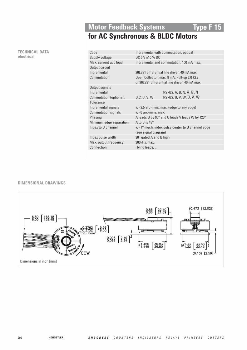
206 E N C O D E R S C O U N T E R S I N D I C A T O R S R E L A Y S P R I N T E R S C U T T E R S
Motor Feedback Systemsfor AC Synchronous & BLDC Motors
Type F 15
TECHNICAL DATAelectrical
DIMENSIONAL DRAWINGS
Dimensions in inch [mm]
Code Incremental with commutation, opticalSupply voltage DC 5 V ±10 % DCMax. current w/o load Incremental and commutation: 100 mA max.Output circuit Incremental 26LS31 differential line driver, 40 mA max.Commutation Open Collector, max. 8 mA; Pull-up 2.0 KΩ
or 26LS31 differential line driver, 40 mA max.Output signalsIncremental RS 422: A, B, N, , , Commutation (optional): O.C: U, V, W RS 422: U, V, W, , , ToleranceIncremental signals +/- 2.5 arc-mins. max. (edge to any edge)Commutation signals +/- 6 arc-mins. max.Phasing A leads B by 90° and U leads V leads W by 120°Minimum edge separation A to B is 45°Index to U channel +/- 1° mech. index pulse center to U channel edge
(see signal diagram)Index pulse width 90° gated A and B highMax. output frequency 300kHz, max.Connection Flying leads, ...
WVUNBA

207E N C O D E R S C O U N T E R S I N D I C A T O R S R E L A Y S P R I N T E R S C U T T E R S
Motor Feedback Systemsfor AC Synchronous & BLDC Motors
Type F 15
SIGNAL DIAGRAM
Waveforms below show relationship betweenCH, N, U, V & W (scale differs from above)
ccw shaft rotation
CONNECTION DIAGRAM Function 1 ColourVCC redGND black
blue/blackA blue
green/blackB green
violet/blackN violet
brown/blackU brown
grey/blackV grey
white/blackW whiteW
V
U
N
B
A
1 availability of function depends on version
N
N

208 E N C O D E R S C O U N T E R S I N D I C A T O R S R E L A Y S P R I N T E R S C U T T E R S
Motor Feedback Systemsfor AC Synchronous & BLDC Motors
Type F 15
1 Uinc: Supply voltage incremental,Ucom: Supply voltage commutation (only if commutation is selected)
2 allowed combinations see available combinations (pulses/poles)
ORDERING INFORMATION
MountingPulses pprincremental 2Type
0 Servoringsize 15
1 0242 048
F15-
Polescommutation 2
0 without6 6 pole8 8 poleC 10 pole
-/
Electrical 1
incremental onlywithout commutation3 Uinc=DC 5 V;
outputinc=RS 422incremental plus commutation signals6 Uinc=DC 5 V;
outputinc=RS 422,Ucom=DC 5 V; outputcom=NPN-O.C.
9 Uinc=DC 5 V; outputinc=RS 422,Ucom=DC 5 V; outputcom=RS 422
Shaft / Bore Connection
1 9.52 mm throughbore
0 16.5 cm Flying leads
Available combinations (pulses/poles)
Number of polesPulses ppr 0 6 8 10 (=C)1024 X X X X2048 X X X X

209E N C O D E R S C O U N T E R S I N D I C A T O R S R E L A Y S P R I N T E R S C U T T E R S
Weight approx. 90 gDimensions Outside diameter: 52.4 mm max.;
Hight: 25.7 mm max.Material Housing: cast-aluminium;
Servo ring: aluminium;Hub: brass; Disk: 0.76 mm thick glass
Moment of inertia 2.5 gcm2
Hollow shaft diameter 12.7 mmHollow shaft balance +0.001"/-0.000" (+0.025 mm/-0.000 mm)Radial runout of ±0.05 mm max. (includes shaft perpendicularitymating shaft to mounting surface)Axial endplay of ±0.25 mm max.mating shaftMounting 2.062" (52.4 mm) flexible servo ring
(size 21 pancake resolver equivalent)Acceleration 100 000 rad/s2 max.Max. speed 5 000 min-1 continuous;
12 000 min-1 peakBearing life [(3.6 x 10⁹) / RPM] hours;
e.g. 605 000 hours at 6 000 RPMOperating temperature 0° ... +120 °CStorage temperature 0° ... +120 °CShock resistance 50 g for 6 ms durationVibration resistance 2.5 g at 5 to 2 000 HzRelative humidity 90 % non-condensing
Motor Feedback Systemsfor AC Synchronous & BLDC Motors
Type F 21
■ Compact hollowshaft motor encoder, ideal for BLDC,DC-Servo and Stepper feedback
■ Resolver compatible mounting■ Resolution up to 2 048 ppr■ Operating temperature up to 120 °C ■ Frequency response to 300 kHz■ Mounting depth 22.4 mm
GENERAL INFORMATION The type F21 encoder provides high performance, cost effective feedback for stepper andservo motor applications. The F21 offers compact package dimensions and flying leads fora low-profile installation. A size 21 servo ring allows easy mounting and replacement ofpancake resolvers with high tolerance to motor shaft movement and 360 degrees of adjustment to align the signal outputs to the shaft position.
TECHNICAL DATAmechanical
NUMBER OF PULSES 1024, 2048; optional additional 6, 8, 10, 12 or 16 pole commutation signals

210 E N C O D E R S C O U N T E R S I N D I C A T O R S R E L A Y S P R I N T E R S C U T T E R S
Motor Feedback Systemsfor AC Synchronous & BLDC Motors
Type F 21
TECHNICAL DATAelectrical
DIMENSIONAL DRAWINGS
Dimensions in inch [mm]
Code Incremental with commutation, opticalSupply voltage DC 5 V ±10 % DCMax. current w/o load Incremental and commutation: 100 mA max.Output circuit Incremental 26LS31 differential line driver, 40 mA max.Commutation Open Collector, max. 8 mA; Pull-up 2.0 KΩ
or 26LS31 differential line driver, 40 mA max.Output signalsIncremental RS 422: A, B, N, , , Commutation (optional): O.C: U, V, W RS 422: U, V, W, , , AccuracyIncremental signals +/- 2.5 arc-mins. max. (edge to eny edge)Commutation signals +/- 6 arc-mins. max.Phasing A leads B by 90° and U leads V leads W by 120°Minimum edge separation A to B is 45°Index to U channel +/- 1° mech. index pulse center to U channel edge
(see signal diagram)Index pulse width 90° gated A and B highMax. output frequency 300kHz, max.Connection Flying leads, ...
WVUNBA

211E N C O D E R S C O U N T E R S I N D I C A T O R S R E L A Y S P R I N T E R S C U T T E R S
Motor Feedback Systemsfor AC Synchronous & BLDC Motors
Type F 21
SIGNAL DIAGRAM
Waveforms below show relationship betweenCH, N, U, V & W (scale differs from above)
ccw shaft rotation
CONNECTION DIAGRAM Function 1 ColourVCC redGND black
blue/blackA blue
green/blackB green
violet/blackN violet
brown/blackU brown
grey/blackV grey
white/blackW whiteW
V
U
N
B
A
1 availability of function depends on version
N
N

212 E N C O D E R S C O U N T E R S I N D I C A T O R S R E L A Y S P R I N T E R S C U T T E R S
Motor Feedback Systemsfor AC Synchronous & BLDC Motors
Type F 21
ORDERING INFORMATION
MountingPulses pprincremental 2Type
0 Servoringsize 21
1 0242 048
F21-
Polescommutation 2
0 without6 6 pole8 8 poleC 10 poleE 12 poleI 16 pole
-/
Electrical 1
incremental onlywithout commutation3 Uinc=DC 5 V;
outputinc=RS 422incremental plus commutation signals6 Uinc=DC 5 V;
outputinc=RS 422,Ucom=DC 5 V; outputcom=NPN-O.C.
9 Uinc=DC 5 V; outputinc=RS 422,Ucom=DC 5 V; outputcom=RS 422
Shaft / Bore Connection
3 12.7 mm throughbore
0 16.5 cm Flying leads
Available combinations (pulses/poles)
1 Uinc: Supply voltage incremental,Ucom: Supply voltage commutation (only if commutation is selected)
2 allowed combinations see available combinations (pulses/poles)
Number of polesPulses ppr 0 6 8 10 (=C) 12 (=E) 16 (=I)1024 X X X X X X2048 X X X X X X

213E N C O D E R S C O U N T E R S I N D I C A T O R S R E L A Y S P R I N T E R S C U T T E R S
Shaft Through hollow shaftShaft diameter 6.8 mm; 1 ⁄ 4”Shaft tolerance +0.025 / -0.000 mmMoment of inertia 5.8 gcm2
Axial endplay of mating shaft ±1.5 mmRadial runout of mating shaft 0.05 mm (includes shaft perpendicularity)Max. speed (Frequency / ppr) x 60 or
12 000 min-1, whichever is lessBearing life (1.4 x 10⁹) / RPM [hours]
e.g. 230 000 hours at 6 000 RPMProtection class IP40 (with cover)Operating temperature 0 ... +120 °CStorage temperature -40 ... +120 °CShock resistance 1000 m/s2 (11 ms)Vibration resistance 25 m/s2 (5...2 000 Hz)Material housing Aluminium
TECHNICAL DATAmechanical
Motor Feedback Systemsfor AC Synchronous & BLDC Motors
Type F 14
■ Compact hollowshaft motor encoder, ideal for BLDC,DC-Servo and Stepper feedback
■ Incremental & commutation■ Phased Array Technology■ Up to 5 000 ppr■ Frequency response to 500 kHz■ Operating temperature up to 120°C■ Trough hollow shaft up to diameter 8 mm■ Stator coupling■ External diameter 40 mm■ Cable plug-in radial/axial
GENERAL INFORMATION The type F14 offers compact package dimensions and a pluggable pin header. A complianttether allows easy mounting with high tolerance to motor shaft movement and 30 degreesof adjustment to align the signal outputs to the shaft position.
A superior optical configuration allows for generous internal component clearance eliminating potential damage at high ambient operating temperatures. High temperaturerated grease is standard for extended bearing life. No special tools are required forinstallation.
The use of optically-generated signals for Brushless DC (BLDC) servo control provides higher accuracy and reliability by eliminating the hysteresis found in competitive units withhall effect sensors, ensuring maximum performance and reliability of the servo system.
NUMBER OF PULSES 200, 400, 500, 1000, 1024, 2000, 2048, 2500, 4096, 5000; optional additional 4, 6, 8 or 10 pole commutation signals
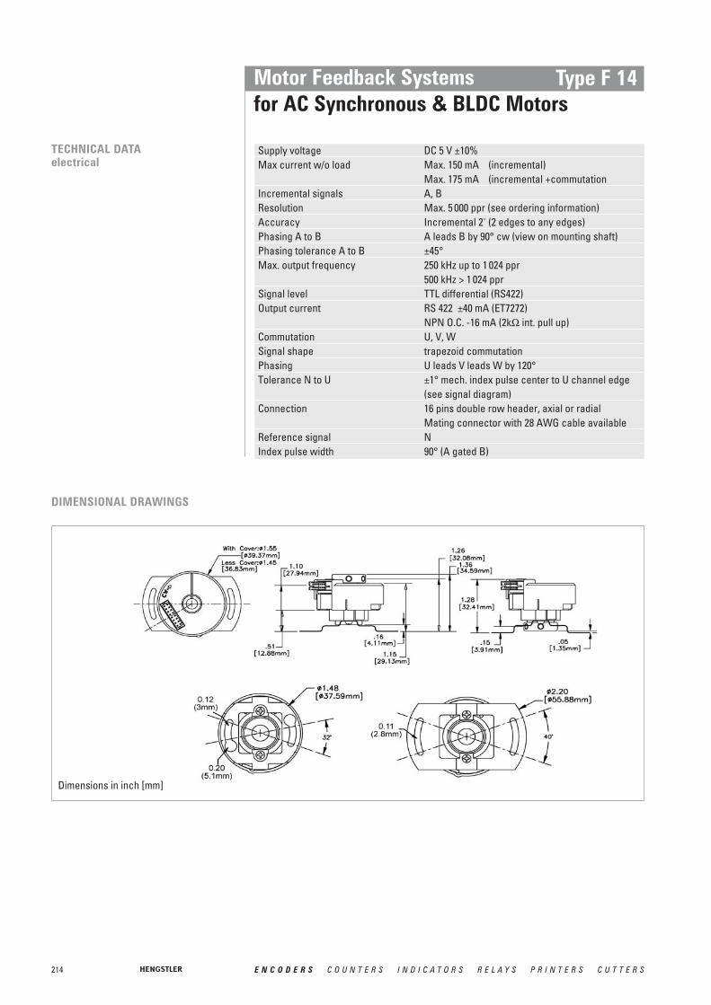
214 E N C O D E R S C O U N T E R S I N D I C A T O R S R E L A Y S P R I N T E R S C U T T E R S
Motor Feedback Systemsfor AC Synchronous & BLDC Motors
Type F 14
TECHNICAL DATAelectrical
Supply voltage DC 5 V ±10%Max current w/o load Max. 150 mA (incremental)
Max. 175 mA (incremental +commutationIncremental signals A, BResolution Max. 5 000 ppr (see ordering information)Accuracy Incremental 2' (2 edges to any edges)Phasing A to B A leads B by 90° cw (view on mounting shaft)Phasing tolerance A to B ±45°Max. output frequency 250 kHz up to 1 024 ppr
500 kHz > 1 024 pprSignal level TTL differential (RS422)Output current RS 422 ±40 mA (ET7272)
NPN O.C. -16 mA (2kΩ int. pull up)Commutation U, V, WSignal shape trapezoid commutationPhasing U leads V leads W by 120°Tolerance N to U ±1° mech. index pulse center to U channel edge
(see signal diagram)Connection 16 pins double row header, axial or radial
Mating connector with 28 AWG cable availableReference signal NIndex pulse width 90° (A gated B)
DIMENSIONAL DRAWINGS
Dimensions in inch [mm]

215E N C O D E R S C O U N T E R S I N D I C A T O R S R E L A Y S P R I N T E R S C U T T E R S
CONNECTION DIAGRAM Pin Function 1 Colour1 VCC red2 U brown3 GND black4 V grey5 A blue6 W white7 blue/black8 - -9 B green10 brown/black11 green/black12 grey/black13 N violet14 white/black15 violet/black16 - -
NW
VBU
A
1 Availability of function depends on version
Motor Feedback Systemsfor AC Synchronous & BLDC Motors
Type F 14
SIGNAL DIAGRAM
CONNECTION
N
Rotation cwView on mounting shaft
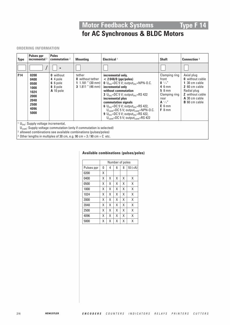
216 E N C O D E R S C O U N T E R S I N D I C A T O R S R E L A Y S P R I N T E R S C U T T E R S
Motor Feedback Systemsfor AC Synchronous & BLDC Motors
Type F 14
1 Uinc: Supply voltage incremental,Ucom: Supply voltage commutation (only if commutation is selected)
2 allowed combinations see available combinations (pulses/poles)3 Other lengths in multiples of 30 cm, e.g. 90 cm = 3 / 90 cm = C etc.
ORDERING INFORMATION
MountingPulses pprincremental 2Type
tether0 without tether1 1.181 ‘’ (30 mm)3 1.811 ‘’ (46 mm)
02000400 05001000102420002048250040965000
F14
Polescommutation 2
0 without4 4 pole6 6 pole8 8 poleA 10 pole
-/
Electrical 1
incremental only, < 2 048/0 (ppr/poles)0 Uinc=DC 5 V; outputinc=NPN-O.C.incremental onlywithout commutation3 Uinc=DC 5 V; outputinc=RS 422incremental plus commutation signals6 Uinc=DC 5 V; outputinc=RS 422,
Ucom=DC 5 V; outputcom=NPN-O.C.9 Uinc=DC 5 V; outputinc=RS 422,
Ucom=DC 5 V; outputcom=RS 422
Connection 3Shaft
Clamping ringfront0 1 ⁄ 4”4 6 mm5 8 mmClamping ringrearA 1 ⁄ 4”E 6 mmF 8 mm
Axial plug0 without cable1 30 cm cable2 60 cm cableRadial plugZ without cableA 30 cm cableB 60 cm cable
Available combinations (pulses/poles)
Number of polesPulses ppr 0 4 6 8 10 (=A)0200 X0400 X X X X X0500 X X X X X1000 X X X X X1024 X X X X X2000 X X X X X2048 X X X X X2500 X X X X X4096 X X X X X5000 X X X X X

217E N C O D E R S C O U N T E R S I N D I C A T O R S R E L A Y S P R I N T E R S C U T T E R S
Shaft Through hollow shaftShaft diameter 6, 8, 10, 12 mm;
1 ⁄ 4”, 3 ⁄ 9”, 7 ⁄ 16”, 1 ⁄ 2”Shaft tolerance +0.025 / -0.000 mmMoment of inertia 37.3 gcm2
Axial endplay of mating shaft ±1.5 mmRadial runout of mating shaft 0.05 mm (includes shaft perpendicularity)Max. speed (Frequency / ppr) x 60 or
12 000 min-1, whichever is lessBearing life (3.6 x 10⁹) / min-1 [hours]
e.g. 605 000 hours at 6 000 min-1
Protection class IP40 (with cover)Operating temperature 0 ... +120 °CStorage temperature -40 ... +120 °CShock resistance 1000 m/s2 (11 ms)Vibration resistance 25 m/s2 (5...2 000 Hz)Material housing Aluminium
TECHNICAL DATAmechanical
Motor Feedback Systemsfor AC Synchronous & BLDC Motors
Type F 18
■ Compact hollowshaft motor encoder, ideal for BLDC,DC-Servo and Stepper feedback
■ Incremental & commutation■ Phased Array Technology■ Up to 10 000 ppr■ Frequenquy response to 500 kHz■ Operating temperature up to 120°C■ Trough hollow shaft up to diameter 12.7 mm■ Stator coupling■ External diameter 50 mm■ Cable plug-in radial/axial
GENERAL INFORMATION The type F18 encoder provides high performance, cost effective feedback for stepper andservo motor controls. The F18 offers compact package dimensions and a pluggable pinheader. A compliant tether allows easy mounting with high tolerance to motor shaft movement and 30 degrees of adjustment to align the signal outputs to the shaft position.
A superior optical configuration allows for generous internal component clearanceeliminating potential damage at high ambient operating temperatures. High temperaturerated grease is standard for extended bearing life. No special tools are required for installation.
The use of optically-generated signals for Brushless DC (BLDC) servo control provideshigher accuracy and reliability by eliminating the hysteresis found in competitive units withhall effect sensors, ensuring maximum performance and reliability of the servo system.
NUMBER OF PULSES 500, 512, 1000, 1024, 2000, 2048, 2500, 4096, 5000, 8192, 10 000; optional additional 4, 6, 8, 10, 12 or 16 pole commutation signals

218 E N C O D E R S C O U N T E R S I N D I C A T O R S R E L A Y S P R I N T E R S C U T T E R S
Motor Feedback Systemsfor AC Synchronous & BLDC Motors
Type F 18
TECHNICAL DATAelectrical
Supply voltage DC 5 V ±10%Max current w/o load Max. 150 mA (incremental)
Max. 175 mA (incremental +commutationIncremental signals A, BResolution Max. 10 000 ppr (see ordering information)Accuracy Incremental 2' (2 edges to any edges)Phasing A to B A leads B by 90° ccw (view on mounting shaft)Phasing tolerance A to B ±45°Max. output frequency 250 kHz up to 1 024 ppr
500 kHz > 1 024 pprSignal level TTL differential (RS422)Output current RS 422 ±40 mA (ET7272)
NPN O.C. -16 mA (2kΩ int. pull up)Commutation U, V, WSignal shape trapezoid commutationPhasing U leads V leads W by 120°Tolerance N to U ±1° mech. index pulse center to U channel edge
(see signal diagram)Connection 16 pins double row pin header, axial or radial
Mating connector with 28 AWG cable availableReference signal NIndex pulse width 90° (A gated B)
DIMENSIONAL DRAWINGS
Dimensions in inches (mm)

219E N C O D E R S C O U N T E R S I N D I C A T O R S R E L A Y S P R I N T E R S C U T T E R S
Motor Feedback Systemsfor AC Synchronous & BLDC Motors
Type F 18
CONNECTION DIAGRAM Pin Function 1 Colour1 VCC red2 U brown3 GND black4 V grey5 A blue6 W white7 blue/black8 - -9 B green10 brown/black11 green/black12 grey/black13 N violet14 white/black15 violet/black16 - -
NW
VBU
A
1 Availability of function depends on version
SIGNAL DIAGRAM
CONNECTION
N
Rotation cwView on mounting shaft

220 E N C O D E R S C O U N T E R S I N D I C A T O R S R E L A Y S P R I N T E R S C U T T E R S
Motor Feedback Systemsfor AC Synchronous & BLDC Motors
Type F 18
1 Uinc: Supply voltage incremental,Ucom: Supply voltage commutation (only if commutation is selected)
2 allowed combinations see available combinations (pulses/poles)3 Other lengths in multiples of 30 cm, e.g. 90 cm = 3 / 90 cm = C etc.
ORDERING INFORMATION
MountingPulses pprincremental 2Type
tether0 without
tether2 1.575‘’
(40 mm) TK3 1.811‘’
(46 mm) TK4 2.376’’
(60 mm) TK5 2.60‘’
(66 mm) TK
050005121000102420002048250040965000819210E3 = 10 000
F18
Polescommutation 2
0 without4 4 pole6 6 pole8 8 poleA 10 poleC 12 poleG 16 pole
-/
Electrical 1
incremental only, < 2 048/0 (ppr/poles)0 Uinc=DC 5 V; outputinc=NPN-O.C.incremental onlywithout commutation3 Uinc=DC 5 V; outputinc=RS 422incremental plus commutation signals6 Uinc=DC 5 V; outputinc=RS 422,
Ucom=DC 5 V; outputcom=NPN-O.C.9 Uinc=DC 5 V; outputinc=RS 422,
Ucom=DC 5 V; outputcom=RS 422
Connection 3Shaft
Clamping ring front0 1 ⁄ 4” 4 6 mm1 3 ⁄ 8” 5 8 mm2 7 ⁄ 16” 6 10 mm3 1 ⁄ 2” 7 12 mmClamping ring rearA 1 ⁄ 4” E 6 mmB 3 ⁄ 8” F 8 mmC 7 ⁄ 16” G 10 mmD 1 ⁄ 2” H 12 mm
Axial plug0 without cable1 30 cm cable2 60 cm cableRadial plugZ without cableA 30 cm cableB 60 cm cable
Available combinations (pulses/poles)
Number of polesPulses ppr 0 4 6 8 10 (=A) 12 (=C) 16 (=X)0500 X X X X X X0512 X X X X1000 X X X X X X1024 X X X X X2000 X X X X X X2048 X X X X X X X2500 X X X X X X4096 X X X X X X X5000 X X X X X X8129 X X X X X X X10E3 = 10 000 X X X X X X
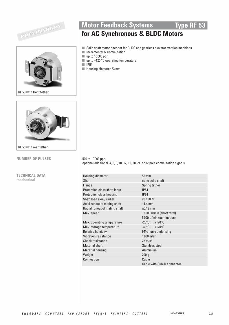
221E N C O D E R S C O U N T E R S I N D I C A T O R S R E L A Y S P R I N T E R S C U T T E R S
Housing diameter 53 mmShaft cone solid shaftFlange Spring tetherProtection class shaft input IP54Protection class housing IP54Shaft load axial/ radial 20 / 90 NAxial runout of mating shaft ±1.4 mmRadial runout of mating shaft ±0.18 mmMax. speed 12 000 U/min (short term)
5 000 U/min (continuous)Max. operating temperature -20°C … +120°CMax. storage temperature -40°C … +120°CRelative humidity 95% non-condensingVibration resistance 1 000 m/s²Shock resistance 25 m/s²Material shaft Stainless steelMaterial housing AluminiumWeight 200 gConnection Cable
Cable with Sub-D connector
TECHNICAL DATAmechanical
Motor Feedback Systemsfor AC Synchronous & BLDC Motors
Type RF 53
■ Solid shaft motor encoder for BLDC and gearless elevator traction machines■ Incremental & Commutation■ up to 10 000 ppr■ up to +120 °C operating temperature■ IP54■ Housing diameter 53 mm
NUMBER OF PULSES 500 to 10 000 ppr; optional additional 4, 6, 8, 10, 12, 16, 20, 24 or 32 pole commutation signals
RF 53 with front tether
RF 53 with rear tether
PPRREELLIIMMIINNAARRYY

222 E N C O D E R S C O U N T E R S I N D I C A T O R S R E L A Y S P R I N T E R S C U T T E R S
Motor Feedback Systemsfor AC Synchronous & BLDC Motors
Type RF 53
TECHNICAL DATAelectrical
Supply voltage DC 5 ±10%Max. current w/o load 100 mACode Incremental with commutation option, opticalToleranceIncremental signals ±2,5 arc-mins. max. (edge to edge)Commutation ±6 arc-mins. max.Phasing A to B by 90° and U to W by 120°Minimum edge separation A to B 45°Index pulse width 90° gated A and B highOutput frequency max. 100 kHzOutput circuit Differential line driver (ET7272), 40 mA max.
Open Collector, max. 8 mA; Pull up with 2,0 kOhmOutput versions RS 422 (incr.): A, B, N, , ,
RS 422 (incr. + com.): A, B, N, , , , U, V, W, , , RS 422 (incr.) + OC-NPN (com.): A, B, N, , , , U, V, WOC-NPN (incr.): A,B,N
NBA
WVUNBANBA
DIMENSIONAL DRAWINGS
FRONT TETHER
Dimensions in mm

223E N C O D E R S C O U N T E R S I N D I C A T O R S R E L A Y S P R I N T E R S C U T T E R S
Motor Feedback Systemsfor AC Synchronous & BLDC Motors
Type RF 53
REAR TETHER
SIGNAL FORMAT
N
Rotation cwView on mounting shaft
PIN ASSIGNMENT PIN Signal Color SUB-D 15 PIN1 DC 5 V red 132 U brown 73 0 V black 144 V grey 95 A blue 16 W white 117 blue/black 28 N.C.9 B green 310 brown/black 811 green/black 612 grey/black 1013 N violet N.C.14 white/black 1215 violet/black N.C.16 N.C.
NW
VBU
A
PCB Connector
Sub-D- Connector
Dimensions in mm
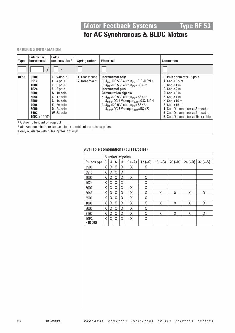
224 E N C O D E R S C O U N T E R S I N D I C A T O R S R E L A Y S P R I N T E R S C U T T E R S
Motor Feedback Systemsfor AC Synchronous & BLDC Motors
Type RF 53
1 Option redundant on request2 allowed combinations see available combinations pulses/ poles3 only available with pulses/poles ≤ 2048/0
ORDERING INFORMATION
Spring tetherPulses ppr incremental 1Type
1 rear mount2 front mount
050005121000102420002048250040965000819210E3 = 10 000
RF53
Polescommutation 2
0 without4 4 pole6 6 pole8 8 poleA 10 poleC 12 poleG 16 poleK 20 poleO 24 poleW 32 pole
-/
Electrical
Incremental only0 Uinc=DC 5 V; outputinc=O.C.-NPN 33 Uinc=DC 5 V; outputinc=RS 422Incremental plus Commutation signals6 Uinc=DC 5 V; outputinc=RS 422
Ucom=DC 5 V; outputcom=O.C.-NPN9 Uinc=DC 5 V; outputinc=RS 422,
Ucom=DC 5 V; outputcom=RS 422
Connection
0 PCB connector 16 poleA Cable 0.5 mB Cable 1 mC Cable 2 mD Cable 3 mE Cable 7 mK Cable 10 mP Cable 15 m1 Sub-D connector at 3 m cable2 Sub-D connector at 5 m cable3 Sub-D connector at 10 m cable
Available combinations (pulses/poles)
Number of polesPulses ppr 0 4 6 8 10 (=A) 12 (=C) 16 (=G) 20 (=K) 24 (=O) 32 (=W)0500 X X X X X X0512 X X X X1000 X X X X X X1024 X X X X X2000 X X X X X X2048 X X X X X X X X X X2500 X X X X X X4096 X X X X X X X X X X5000 X X X X X X8192 X X X X X X X X X X10E3 X X X X X X=10 000

225E N C O D E R S C O U N T E R S I N D I C A T O R S R E L A Y S P R I N T E R S C U T T E R S
Absolute Motor Feedback Systemsfor AC Synchronous & BLDC Motors
Type AD 36
■ For brushless servo motors■ Resolver size 15 compatible■ Through hollow shaft 8 mm■ 19 Bit Singleturn + 12 Bit Multiturn■ + 120°C operating temperature■ 10.000 rpm continuous operation■ Geared optical multiturn■ SSI or BiSS interface■ Sinewave 1 Vpp■ Bandwidth 500kHz
GENERAL INFORMATION The AD36 is an absolute encoder with a true geared Multiturn, optical sensing technologyand 36 mm diameter. Unique is the through hollow shaft which enables an assembly that iscompatible with resolver size 15. The mechanical design consists of two ball bearings anda flexible torque support. The AD36 complements the ACURO-DRIVE series and is appro-priate for use within BLDC servo motors with small frame sizes.
Fully digital control loopThe new and completely digital OptoAsic technology enables the transition to a truly digitaldrive system. The conventional absolute encoders still have analog sine wave signals for thefeedback of speed and position data. The AD36, however, provides fully digital position dataup to 19 Bit (Singleturn) and 12 Bit (Multiturn) over the BiSS interface with a variable clockrate up to 10 MHz. BiSS is the only open high speed bidirectional sensor interface availableon the market. Backward compatibility to most of the existing drives is realized through the variant with SSIinterface together with 2048 sine –cosine periods per revolution.
Integrated diagnostic systemThe AD36 has an integrated diagnostic system that controls and regulates the internal signals. Maximum motor uptime is achieved through the pre warning in case of any systemerror or aging effects well before they affect the function of the encoder. A code plausibilitycheck guarantees that the output data represents always the true position. Also the operating temperature can be measured and read out with 8 Bit resolution. If programmablelimits are exceeded or under run this is indicated over warn and alarm bits.
TECHNICAL DATAmechanical
Housing diameter 37,5 mm Shaft diameter 8 mm Protection class housing IP40Protection class shaft IP40Max. speed Continuous operation 10 000 min-1
Short term operation 12 000 min-1
Torque 0,01 NmMoment of inertia 25 gcm2
Spring tether (hollow shaft)Tolerance axial ± 0,5 mmTolerance radial ± 0,05 mmVibration resistance (IEC 68-2-6) 100 m/ s2 (10 - 500 Hz)Shock resistance (IEC 68-2-27) 1000 m/ s2 (6 ms) Operating temperature -15 ...+120°C Storage temperature -15 ...+85°C Material shaft/ housing AluminumWeight ST/ MT 80 g/ 130 g
PPRREELLIIMMIINNAARRYY
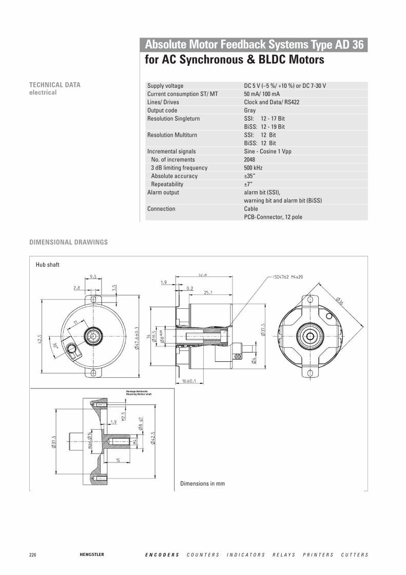
226 E N C O D E R S C O U N T E R S I N D I C A T O R S R E L A Y S P R I N T E R S C U T T E R S
Absolute Motor Feedback Systemsfor AC Synchronous & BLDC Motors
Type AD 36
TECHNICAL DATAelectrical
Supply voltage DC 5 V (–5 %/ +10 %) or DC 7-30 VCurrent consumption ST/ MT 50 mA/ 100 mALines/ Drives Clock and Data/ RS422Output code GrayResolution Singleturn SSI: 12 - 17 Bit
BiSS: 12 - 19 BitResolution Multiturn SSI: 12 Bit
BiSS: 12 BitIncremental signals Sine - Cosine 1 Vpp
No. of increments 20483 dB limiting frequency 500 kHzAbsolute accuracy ±35“Repeatability ±7“
Alarm output alarm bit (SSI), warning bit and alarm bit (BiSS)
Connection Cable PCB-Connector, 12 pole
DIMENSIONAL DRAWINGS
Hub shaft
Dimensions in mm

227E N C O D E R S C O U N T E R S I N D I C A T O R S R E L A Y S P R I N T E R S C U T T E R S
Absolute Motor Feedback Systemsfor AC Synchronous & BLDC Motors
Type AD 36
ORDERING INFORMATION
Supply voltage Flange, Protection, ShaftResolution Interface ConnectionType
A DC 5 VE DC 7 - 30 V
F.0C Spring tether, IP40, 8 mm trough hollow shaft
F.0R Spring tether, IP40, 8 mm hub shaft
0012 12 Bit ST0013 13 Bit ST0014 14 Bit ST0017 17 Bit ST0019 19 Bit ST (BiSS)1213 12 Bit MT+13 Bit ST1217 12 Bit MT+17 Bit ST1219 12 Bit MT
+19 Bit ST (BiSS)
AD 36 SC SSI Gray+1 Vpp
BI BiSS
0 PCB-connector, 12 pole
B Cable radial0.5m
PIN ASSIGNMENT
Through hollow shaft
Colour new Colour old PIN Signalsgrey violet 1awhite/green green 2a A +black brown/ green 3a 0 V Sensorred/blue blue 4a B +green brown 5aviolet red/ black 6a 5 V Sensorwhite yellow/ black 1b DC 5 V/ 7 - 30 Vyellow white 2b Clockgrey/pink red 3b B -brown white/ green 4b 0 V (UN)brown/green yellow 5b A -pink black 6b Data
Clock
Data
Connector:12 pin PCB connectorManufacture BergType: Minitec
Dimensions in mm

228 E N C O D E R S C O U N T E R S I N D I C A T O R S R E L A Y S P R I N T E R S C U T T E R S
Absolute Motor Feedback Systemsfor AC Synchronous & BLDC Motors
Type AD 58
■ For brushless servo motors■ All-digital and highspeed■ + 120°C operating temperature■ 10.000 rpm continuous operation■ Geared optical multiturn■ SSI or BiSS interface■ Option Sinewave 1 Vpp: Harmonic distortion less than 1%■ Bandwidth 500kHz
GENERAL INFORMATION The AD 58 is an absolute encoder with a true geared Multiturn and optical sensingtechnology: The mechanical design consists of two ball bearings and a flexible torque support. The AD58 is ideally suited for integration into BLDC servo motors for demanding applications such as CNC precision machining and printing in professionell quality. Through its low current consumption the AD58 is contributing to lowering cost of ownership.
Fully digital control loopThe new and completely digital OptoAsic technology enables the transition to a truly digital drive system. The conventional absolute encoders still have analog sine wave signals for the feedback of speed and position data. The AD 58, however, provides fully digital position data up to 22 Bit (Singleturn) and 12 Bit (Multiturn) over the BiSS interface with a variable clock rate up to 10 MHz. This corresponds a singleturn resolution of morethan 4 million measured steps.
TECHNICAL DATAmechanical
Housing diameter 58 mm Protection class housing IP40Protection class shaft IP40Flange Hubshaft with tether or KonusShaft diameter Cone 10 mm Max. speed Continuous operation 10 000 min-1
Short term operation 12 000 min-1
Torque 0,01 NmMoment of inertia 3.8 x 10⁻⁶ kgm2
Spring tether (hollow shaft)Tolerance axial ± 0,5 mmTolerance radial ± 0,1 mmVibration resistance (IEC 68-2-6) 100 m/ s2 (10 - 2 000 Hz)Shock resistance (IEC 68-2-27) 1000 m/ s2 (6 ms) Operating temperature -15 ...+120°C Storage temperature -15 ...+85°C (because of packing)Weight ST/ MT 260 g/ 310 g
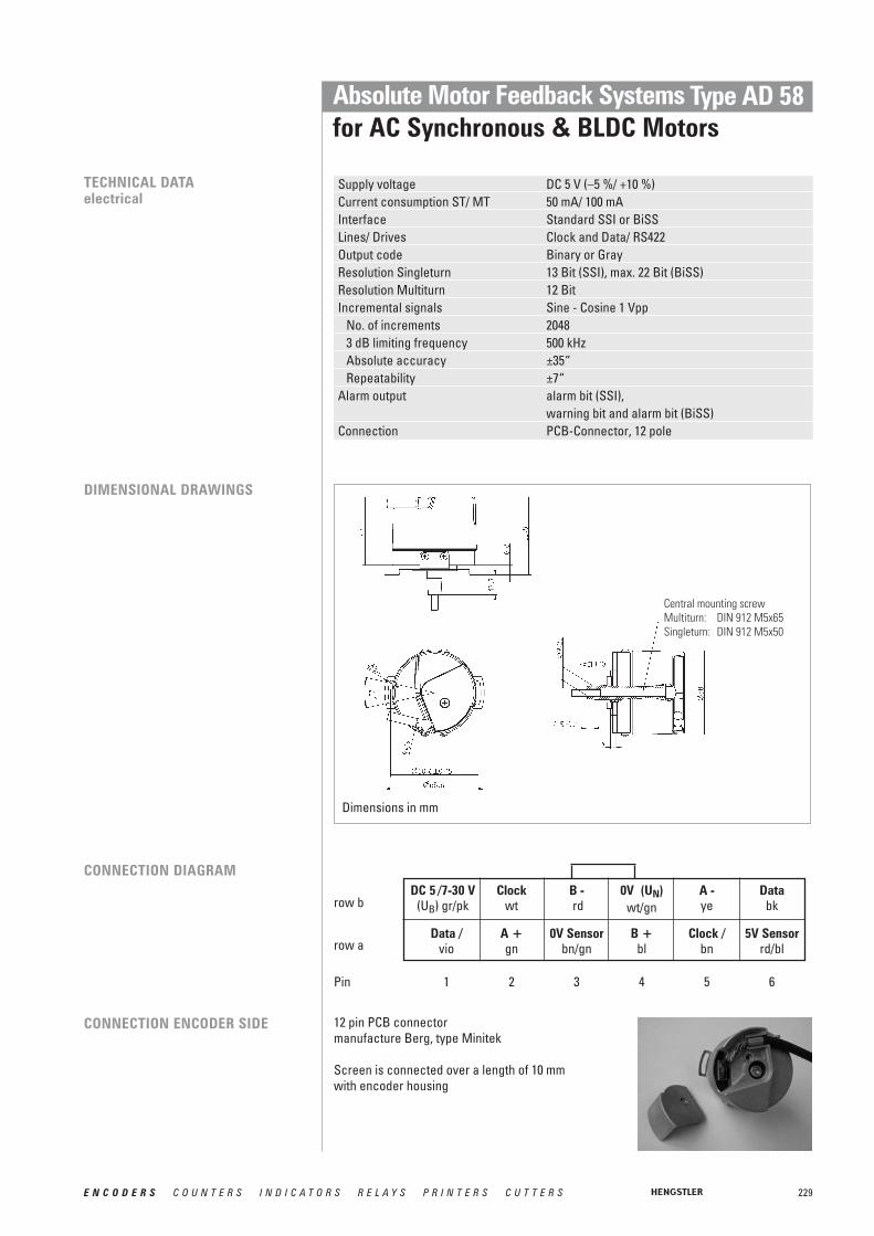
229E N C O D E R S C O U N T E R S I N D I C A T O R S R E L A Y S P R I N T E R S C U T T E R S
Absolute Motor Feedback Systemsfor AC Synchronous & BLDC Motors
Type AD 58
TECHNICAL DATAelectrical
Supply voltage DC 5 V (–5 %/ +10 %)Current consumption ST/ MT 50 mA/ 100 mAInterface Standard SSI or BiSSLines/ Drives Clock and Data/ RS422Output code Binary or GrayResolution Singleturn 13 Bit (SSI), max. 22 Bit (BiSS)Resolution Multiturn 12 BitIncremental signals Sine - Cosine 1 Vpp
No. of increments 20483 dB limiting frequency 500 kHzAbsolute accuracy ±35“Repeatability ±7“
Alarm output alarm bit (SSI), warning bit and alarm bit (BiSS)
Connection PCB-Connector, 12 pole
DIMENSIONAL DRAWINGS
Central mounting screwMultiturn: DIN 912 M5x65Singleturn: DIN 912 M5x50
CONNECTION DIAGRAM
CONNECTION ENCODER SIDE 12 pin PCB connectormanufacture Berg, type Minitek
Screen is connected over a length of 10 mmwith encoder housing
DC 5 /7-30 V(UB) gr/pk
Clockwt
B -rd
0V (UN) wt/gn
A -ye
Databk
Data /vio
A +gn
0V Sensorbn/gn
B +bl
Clock /bn
5V Sensorrd/bl
1 2 3 4 5 6
row b
row a
Pin
Dimensions in mm

230 E N C O D E R S C O U N T E R S I N D I C A T O R S R E L A Y S P R I N T E R S C U T T E R S
Absolute Motor Feedback Systemsfor AC Synchronous & BLDC Motors
Type AD 58
ORDERING INFORMATION
Supply voltage Flange, Protection, ShaftResolution Interface ConnectionType
A DC 5 VE DC 10 - 30 V
1.0K Hubshaft with tether,IP40, Cone 10 mm
0013 13 Bit ST0022 22 Bit ST (BiSS)1213 12 Bit MT+13 Bit ST1222 12 Bit MT+22 Bit ST
(BiSS)
AD58 SC SSI Gray+1 Vpp
BI BiSS (digital)
0 PCB connector12 pole
B PCB connector12 pole with matingconnector and 0.5m cable

231E N C O D E R S C O U N T E R S I N D I C A T O R S R E L A Y S P R I N T E R S C U T T E R S
Motor Feedback Systems - Sine-wave for AC Synchronous & BLDC Motors
Type S21
■ Wide operating temperature range of –15 °C up to +120 °C, therefore optimum use of motor capacity
■ High limiting frequency with excellent signal quality, allowing highest peak speeds andreduced non-productive time wastage
■ Excellent immunity to interference (EN 61000-4-4, Class 4)■ High functional safety due to signal control and system monitoring (under-voltage,
pollution, disc damage, end of LED service life)■ High signal quality through control and error compensation
TECHNICAL DATAelectrical
General design as per DIN EN 61010-1, protection class III, contamination level 2, over voltage class II
Supply voltage DC 5 V ±10 % (SELV)Max. current w/o load 120 mAIncremental signals A,B Sine - Cosine 1 VppNumber of pulses 2 048Accuracy ±35“Repeatability ±7“Max frequency output 500 kHzReference signal: R > 0.4 V (1 pulse per rev.)Commutation signals: C, D Sine - Cosine 1 Vpp (1 period per rev.)Connection PBC connector with cable
TECHNICAL DATAmechanical
Shaft form Cone 1/10Shaft variations Tapered solid shaft
(Tapered hollow shaft on request)Shaft diameter 10 mmShaft load tapered solid shaft radial 90 N, axial 20 NCompensation axial ±0.5 mm, radial ±0.1 mmNominal speed 12 000 min-1
Max. speed 15 000 min-1 (<1s)Torque ≤ 1 NcmProtection class IP40Operating temperature -15 °C ... +120 °CStorage temperature -20 ... +80 °CVibration resistance (IEC 68-2-6) ≤ 100 m/s2 (10 ... 2 000 Hz)Shock resistance (IEC 68-2-27) ≤ 1 000 m/s2 (6 ms)Material housing Aluminium
The S21 has been constructed in line with the International Standard Resolver dimension 21,i.e. 2.1” (approx. 53 mm) and as a result is also suitable for smaller sized motors. The simplicity of connection rounds off advantages of the S21. The integrated cable plug connector combines the advantages of the plug with those of a cable connection. This leads to a fast, economical and space-saving installation.
GENERAL INFORMATION

5 V Sense D- B- R- 0 V Sense A- C- rd/bl vio rd pk gn/br ye brwt gn wt/gn gr bl bk gr/pk C+ A+ GND R+ B+ D+ UB
232 E N C O D E R S C O U N T E R S I N D I C A T O R S R E L A Y S P R I N T E R S C U T T E R S
Motor Feedback Systems - Sine-wave for AC Synchronous & BLDC Motors
Type S21
PCB-CONNECTOR PIN OUTRow a
Row b
Pin
S21 SIGNALS
S21 SIGNAL QUALITY
Signals shown at CW rotation with view on shaft's end
21.81.61.41.2
10.80.60.40.2
020 70 120 170 220 270 320
Signal frequency [kHz]
Harm
onic
dis
torti
on [
%]
The incremental signals A and B and the zero signal R are differential voltage signals. Thedifferential signal level is 1 Vpp. The zero signal appears once per revolution and reaches itsmaximum value at the angle where the amplitudes of A and B Signals are equal. The coarsetracks C and D deliver one sinewave period per revolution and are utilized to determine theabsolute rotor position of Brushless DC motors for startup commutation. All signals have aDC offset of 2.5 V.
The quality of the servo loop is determined to a large extent by the absence of harmonicsin the encoder's sinewave signals, particularly at low speed. In order to achieve high inter-polation factors in the sequencing control, the incremental sinewave signals A and B are available with a harmonic distortion significantly under 1% throughout the specified temperature range. This delivers excellent synchronism and a high level of positional accuracy with servo axes.
BA
DC
R
7 6 5 4 3 2 1

233E N C O D E R S C O U N T E R S I N D I C A T O R S R E L A Y S P R I N T E R S C U T T E R S
Motor Feedback Systems - Sine-wave for AC Synchronous & BLDC Motors
Type S21
ORERING INFORMATION Ordering codeTapered solid shaft with mounting support 0 548 011Tapered hollow shaft on request
DIMENSIONAL DRAWINGSTAPERED SOLID SHAFT
Central mounting screwDIN 912 M5 x 20
Jack
-out
thre
ad
R => 24 mm(for permanant
bending)
Shaft exterior
* Mounting dimensions spring thether on shaft
Dimensions in mm

234 E N C O D E R S C O U N T E R S I N D I C A T O R S R E L A Y S P R I N T E R S C U T T E R S
Motor Feedback Systems Resolversmodular
■ Provide accurate, absolute position feedback■ Rugged and able to withstand high shock and vibration levels■ Impervious to most industrial contaminant and temperatureextremes■ High temperature up to 220°C■ Operation in non electroconductive liquids possible■ Maintenance-free (brushless)■ Aging resistant (no electronic components)■ Low-priced
Application fields:■ Servo drives■ Medical technologie (sterilisable)■ Robots■ Gearless drives■ Military engineering
MODELLÜBERSICHT
DIMENSIONAL DRAWINGS
Type (model) AG P U maximal10BRCX 16.5 mm 26.5 mm 6.0 mm15BRCX 25.4 mm 36.8 mm 12.0 mm21BRCX 31.8 mm 52.4 mm 20.3 mm31BRCX 31.8 mm 77.5 mm 40.0 mm55BRCX 31.8 mm 139.7 mm 92.7 mm
Brushless resolvers are the ideal rotor position indicators for the position feedback of brushless motors, robots or direct drives. They are robust, reliable and suitable for high operating temperatures until 155 °C and resistant to most process liquids, contaminations,radiation and EMC-Interferences as well as highly shock-proof and vibration-resistant.These resolvers deliver absolute position information and can be combined with low costintegrated circuits, to generate an up to 16 bit digital position-value or, to produce an emulated incremental encoder output signal, as well as direction and analogue speed-signals.
Ordering information:Since resolvers are produced according to special applications, the production takes placeonly in big batch sizes. For replacement needs, please contact your drive-manufacturer.

235E N C O D E R S C O U N T E R S I N D I C A T O R S R E L A Y S P R I N T E R S C U T T E R S
Motor Feedback Systems Resolvershoused
HOUSED RESOLVERS SERIES R 11
■ Brushless construction■ Maintenance free■ Able to withstand high shock and vibration levels■ Impervious to most industrial contaminant and temperature extremes■ High temperature up to 115°C
Housed Resolvers distinguish themselves through high reliability in harsh environments,operating temperatures up to 155 °C and high shock resistance. Based on their brushlessdesign they are the ideal supplement to brushless servo motors. The accuracy as well as therepeatability are excellent. These resolvers are equipped with precision bearings and aremaintenance-free. They are also the shortest resolvers, that are available on the market.
DIMENSIONAL DRAWINGS
∅ 3.0 Max.
14.3 40.4
∅ 27
HOUSED INDUSTRY RESOLVERS SERIES R 25
■ Rugged housing with IP65■ Able to withstand high shock and vibration levels■ Impervious to most industrial contaminant and temperature extremes■ High temperature up to 125°C■ Flange- and servo-mount styles
Industry resolvers possess especially robust casings with protection class IP65. They areespecially suitable for the use with high temperatures (+125 °C in long-term operation), andoffer extraordinary values of vibration and shock resistance (40g as well as 200g), as well asnoise immunity. The user is flexible in the application because of the corrosion resistant versions for integration or extension , the connection could easily be done by Standard MS-style connectors. The accuracy has a spread of ± 7 up to ± 200 arc-minutes.
DIMENSIONAL DRAWINGS
Dimensions in inch [mm]
Dimensions in mm

236 E N C O D E R S C O U N T E R S I N D I C A T O R S R E L A Y S P R I N T E R S C U T T E R S
signo 727 SSIAccessories
Problem solutions from a single source.
Our wide range of accessory modules completes the encoder programme.
With these modules, we offer you an optimum means of meeting your application demands.
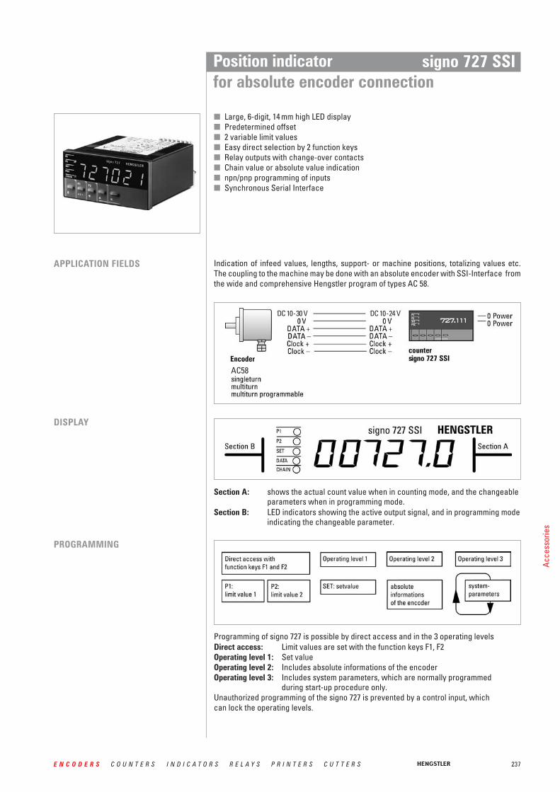
237E N C O D E R S C O U N T E R S I N D I C A T O R S R E L A Y S P R I N T E R S C U T T E R S
Acce
ssor
ies
Position indicatorfor absolute encoder connection
signo 727 SSI
■ Large, 6-digit, 14 mm high LED display■ Predetermined offset■ 2 variable limit values■ Easy direct selection by 2 function keys■ Relay outputs with change-over contacts■ Chain value or absolute value indication■ npn/pnp programming of inputs■ Synchronous Serial Interface
Indication of infeed values, lengths, support- or machine positions, totalizing values etc.The coupling to the machine may be done with an absolute encoder with SSI-Interface fromthe wide and comprehensive Hengstler program of types AC 58.
APPLICATION FIELDS
DISPLAY
Section A: shows the actual count value when in counting mode, and the changeableparameters when in programming mode.
Section B: LED indicators showing the active output signal, and in programming modeindicating the changeable parameter.
PROGRAMMING
Programming of signo 727 is possible by direct access and in the 3 operating levelsDirect access: Limit values are set with the function keys F1, F2Operating level 1: Set valueOperating level 2: Includes absolute informations of the encoderOperating level 3: Includes system parameters, which are normally programmed
during start-up procedure only.Unauthorized programming of the signo 727 is prevented by a control input, whichcan lock the operating levels.
AC58
DC 10-30 V DC 10-24 V

238 E N C O D E R S C O U N T E R S I N D I C A T O R S R E L A Y S P R I N T E R S C U T T E R S
signo 727 SSIPosition indicatorfor absolute encoder connection
TECHNICAL DATA Display LED, indication value/preselection 6 digits, suppression ofleading zeros, programmable decimal point, minus sign
Digit Height 14 mmPower Supply Voltage Ub DC 12 ... 24 V or AC 115/230 V, depending on versionMax. current w/o load DC 12 ... 24 V < 250 mA,
AC 115/230 V < 60 mASensor Supply AC operation DC 12 ...24 V, DC operation UB - 2 V, Imax = 60 mAData Retention non-volatile memory > 10 yearsOperating Temperature 0 ... 50° CStorage Temperature -20 ... +70° CElectrical Connection plug-in terminalsMounting with clamping frameProtection Class (IEC 144) front side IP54, terminals IP20Noise Immunity EMC severity 3 according to IEC 801, part 2 + part 4Vibration resistance 10 m/s2 (10 ... 150 Hz) according to IEC 68-part 2-6Shock resistance 100 m/s2 (18 ms) according to IEC 68-part 2-27General design according to VDE 0411, DIN 57411, protection class IIInputs SSI Data +
SSI Data -Baud rate approx. 100 kHzControl Input Application Input 1, static
Display hold, Reset or Chain Reset(programmable)
Keylock staticOutputs SSI measure +
SSI measure -Relay 1 Out 1 and Out 2Contact Type changeover relaySwitching Voltage max. 250 VAC/30 VDC, mind 5 VAC/DCSwitching Current max. 1A, min. 10 mA
1 for versions with limit values only
signo 727 SSI

239E N C O D E R S C O U N T E R S I N D I C A T O R S R E L A Y S P R I N T E R S C U T T E R S
Position indicatorfor absolute encoder connection
signo 727 SSI
DIMENSIONAL DRAWINGS
Dimensionsin mm
CONNECTION PLAN
ORDERING DATA
opt. with interface RS 485, RS 232 on request
Please note:Absolute encoders with capped Gray Gode (e.g. 360 or 720) must not be connectedMax. encoder resolution: 12 Bit ST (singleturn) and
24 Bit MT (multiturn 12 + 12 Bit)
plug-interminals clamping frame
Type Absolute encoder Supply Ordering codeconnection
signo 727 without limit values SSI DC 12 - 24 V 0 727 111signo 727 without limit values SSI AC 115/230 V 0 727 112signo 727 with 2 limit values SSI DC 12 - 24 V 0 727 131signo 727 with 2 limit values SSI AC 115/230 V 0 727 132
1 L2 -3 -4 N
32 SENSOR: DC 12 - 24 V= /60mA31 0V30 DATA +29 DATA -28 CLOCK +27 CLOCK -26 KEYCLOCK PNP NPN25 APPL. 1 PNP NPN
} SSI !
230V
AC*3
2mAT
115V
AC*3
2mAT AC-POWER
SUPPLY50/60Hz
-L---N }
1 0V DC-POWER2 + DC 12 - 24V- Supply3 NC *0.25A F 0.16A T/IEC 1274 NC *0.25A T 0.20A T/UL 1985 NC6 OUT 17 DC 30 V-/1A 250VAC~/1A8 max. 250V9 NC10 OUT 211 DC 30 V -/1A250VAC~/1A12 max. 250V13 NC14 OUT 1 TR. DC-SUPPLY - 2V/10mA15 OUT 2 TR. DC-SUPPLY - 2V/10mA16 0V32 SENSOR: DC-SUPPLY - 2V/60mA31 0V30 DATA+29 DATA-28 CLOCK+27 CLOCK-26 KEYCLOCK PNP NPN26 APPL PNP NPN
}}
}ext. Fuse*
!} SSI
ext. Fuse*
version without limit values 115/220 VAC Version with limit values DC12/24 V

240 E N C O D E R S C O U N T E R S I N D I C A T O R S R E L A Y S P R I N T E R S C U T T E R S
signo 727 SSIEncoder with Shock Module
AC58-S/M/P WITHOPTIONAL SHOCK MODULE
Applications with vibration rates of up to >100 m/s2 and shock rates >1000 m/s2 require theuse of a shock module. By means of integrated attenuating elements, these encoder ratingsare reduced.
DIMENSIONAL DRAWINGEncoder with shock module,connecting cable
DIMENSIONAL DRAWINGEncoder with shock module,flange connector
ORDERING DATA For the encoder option with shock module, please enquire by stating your desired encoder type.
(Accessories unit 1 540 239Flange ordering code: L.42 for RI 58, K.42 for AC 58)
Fixing flange by means of clamping flange or clamping eccentric, shaft by means of flexible coupling
Absolute max. shaft load axial 30 N, radial 100 NShaft diameter 10 mm
R for alternating bending -> 15 x cable diameterR for permanent bending -> 15 x cable diameter
Dimensions in mm
Dimensions in mm

241E N C O D E R S C O U N T E R S I N D I C A T O R S R E L A Y S P R I N T E R S C U T T E R S
Helical coupling 25/32
Flexible Couplings
Shaft encoders must be protected against excessive mechanical stresses, which occurwhenever there are angular, axial, or radial misalignments between the machine and shaftencoder shafts.Our flexible couplings can compensate for this within limits.
Hub diameter5/5 mm Ordering code 3 520 0365/6 mm Ordering code 3 520 0356/6 mm Ordering code 0 070 6536/6.35 mm Ordering code 3 520 0516.35/6.35 mm Ordering code 3 520 057
Suitable for encoder type RI 30, RI 32,RI 36, RI 41, RI 42, RI 58, AC 58
Max. speed 6 000 min -1
Torque max. 80 NcmMoment of inertia 8.7 gcm2
Torsional spring constant 14 Ncm/degreeMax. angular misalignment ±4°Max. shaft misalignment radial/axial ±0.25 mm / ±0.4 mmMax tightening torque of set screws 80 NcmMaterial AICuMgPb, chromedWeight 16 g
Hub diameter5/5 mm Ordering code 3 520 0345/6 mm Ordering code 3 520 0336/6 mm Ordering code 1 761 026
Suitable for encoder type RI 39RI 32, RI 41, RI 42 for simple applications
Max. speed 10 000 min -1
Torque max. 20 NcmMoment of inertia 1.1 gcm2
Torsional spring constant 12 Nm/radMax. angular misalignment ±2.5°Max. shaft misalignment radial / axial ±0.3 mm / ±0.2 mmMax tightening torque of set screws 70 NcmMaterial polyamide 6.6 glass-fibre reinforcedWeight approx. 6 g
Plastic coupling
Dimensions in mm
Helical coupling 19/28
PLASTIC COUPLING
HELICAL COUPLING
Hub diameter6/9.53 mm Ordering code 3 520 0526/10 mm Ordering code 3 520 0666.35/9.52 mm Ordering code 3 520 06210/12 mm Ordering code 3 520 06510/10 mm Ordering code 3 520 074
Suitable for encoder type RI 58, AC 58
Dimensions in mm Dimensions in mm
Closed-formhub connection
Set screw M3 x 4DIN 916
free interior of beam
Cylinder srews M3 x 10DIN 916 Cylinder srews M3 x 10
DIN 916
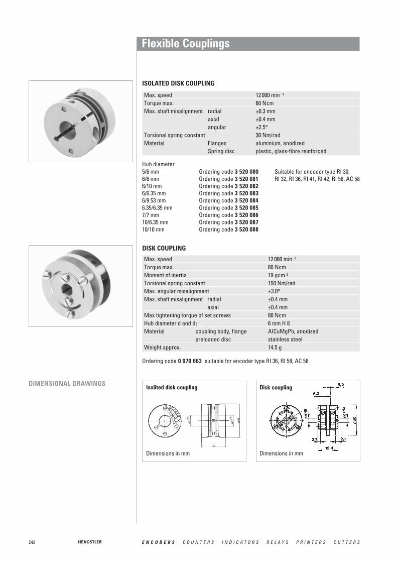
242 E N C O D E R S C O U N T E R S I N D I C A T O R S R E L A Y S P R I N T E R S C U T T E R S
Flexible Couplings
Isolited disk coupling
Dimensions in mm
Disk coupling
Dimensions in mm
ISOLATED DISK COUPLING
DISK COUPLING
DIMENSIONAL DRAWINGS
Max. speed 12 000 min -1
Torque max. 60 NcmMax. shaft misalignment radial ±0.3 mm
axial ±0.4 mmangular ±2.5°
Torsional spring constant 30 Nm/radMaterial Flanges aluminium, anodized
Spring disc plastic, glass-fibre reinforced
Hub diameter5/6 mm Ordering code 3 520 080 Suitable for encoder type RI 30, 6/6 mm Ordering code 3 520 081 RI 32, RI 36, RI 41, RI 42, RI 58, AC 586/10 mm Ordering code 3 520 0826/6.35 mm Ordering code 3 520 0836/9.53 mm Ordering code 3 520 0846.35/6.35 mm Ordering code 3 520 0857/7 mm Ordering code 3 520 08610/6.35 mm Ordering code 3 520 08710/10 mm Ordering code 3 520 088
Ordering code 0 070 663 suitable for encoder type RI 36, RI 58, AC 58
Max. speed 12 000 min -1
Torque max. 80 NcmMoment of inertia 19 gcm 2
Torsional spring constant 150 Nm/radMax. angular misalignment ±3.0°Max. shaft misalignment radial ±0.4 mm
axial ±0.4 mmMax tightening torque of set screws 80 NcmHub diameter d and d1 6 mm H 8Material coupling body, flange AICuMgPb, anodized
preloaded disc stainless steelWeight approx. 14.5 g

243E N C O D E R S C O U N T E R S I N D I C A T O R S R E L A Y S P R I N T E R S C U T T E R S
Flexible Couplings
Bellows coupling
Dimensions in mm
BELLOWS COUPLING
DIMENSIONAL DRAWING
Hub diameter12/12 mm Ordering code 0 070 666 Suitable for type RI 58, AC 5810/10 mm Ordering code 3 520 0379.53/9.53 mm Ordering code 3 520 0386/6 mm Ordering code 3 520 068
Max. speed 8000 min -1
Torque max. 80 NcmMoment of inertia 9 gcm2
Torsional spring constant 140 Nm/radMax. angular misalignment ±4.0°Max. shaft misalignment radial ±0.3 mm
axial ±0.5 mmMax tightening torque of set screws 150 NcmMaterial flange aluminium
bellows stainless steelWeight 16 g
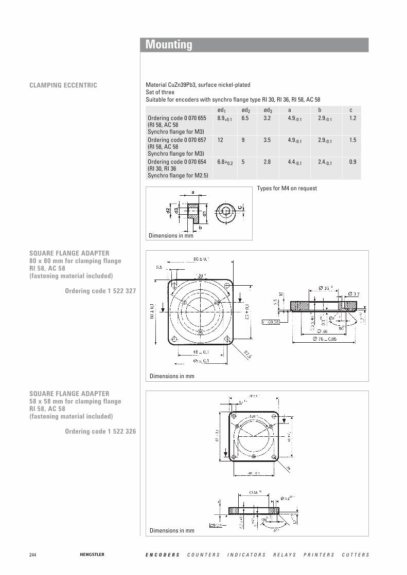
244 E N C O D E R S C O U N T E R S I N D I C A T O R S R E L A Y S P R I N T E R S C U T T E R S
Mounting
Dimensions in mm
Material CuZn39Pb3, surface nickel-plated Set of threeSuitable for encoders with synchro flange type RI 30, RI 36, RI 58, AC 58
ød1 ød2 ød3 a b cOrdering code 0 070 655 8.9+0.1 6.5 3.2 4.9-0.1 2.9-0.1 1.2(RI 58, AC 58Synchro flange for M3)Ordering code 0 070 657 12 9 3.5 4.9-0.1 2.9-0.1 1.5(RI 58, AC 58Synchro flange for M3)Ordering code 0 070 654 6.8+0.2 5 2.8 4.4-0.1 2.4-0.1 0.9(RI 30, RI 36Synchro flange for M2.5)
SQUARE FLANGE ADAPTER58 x 58 mm for clamping flange RI 58, AC 58 (fastening material included)
Ordering code 1 522 326
SQUARE FLANGE ADAPTER80 x 80 mm for clamping flange RI 58, AC 58 (fastening material included)
Ordering code 1 522 327
Dimensions in mm
Dimensions in mm
CLAMPING ECCENTRIC
Types for M4 on request

245E N C O D E R S C O U N T E R S I N D I C A T O R S R E L A Y S P R I N T E R S C U T T E R S
Mounting
SYNCHRO FLANGE ADAPTERfor clamping flange RI 58, AC 58(fastening material included)
Ordering code 1 522 328
SYNCHRO FLANGE ADAPTERfor clamping flange RI 58 (same dimensions as TR HE 65) (fastening material included)
Ordering code 1 522 542
SYNCHRO FLANGE ADAPTERfor clamping flange RI 58 (same dimensions as AG 661) (fastening material included)
Ordering code 1 522 547
Dimensions in mm
Dimensions in mm
Dimensions in mm

246 E N C O D E R S C O U N T E R S I N D I C A T O R S R E L A Y S P R I N T E R S C U T T E R S
Mounting
SYNCHRO FLANGE ADAPTERfor clamping flange RI 58 (same dimensions as AG 100/110) (fastening material included)
Ordering code 1 522 548
BEFESTIGUNGSWINKEL (KUNSTSTOFF)for clamping flange RI 58, AC 58 (fastening material included)
Ordering code 1 522 329
FLANSCH-ADAPTERfor clamping flange AC 58(same dimensions as Gelma RAO 5)(fastening material included)
Ordering code 1 540 336
Dimensions in mm
Dimensions in mm
Dimensions in mm

247E N C O D E R S C O U N T E R S I N D I C A T O R S R E L A Y S P R I N T E R S C U T T E R S
Mounting
MOUNTING BELL (PLASTIC)for synchro flange RI 58, AC 58(clamping eccentric and fastening material included)
Ordering code 1 522 330
Dimensions in mm

248 E N C O D E R S C O U N T E R S I N D I C A T O R S R E L A Y S P R I N T E R S C U T T E R S
Connectors
NUMBERING OF PINS
Clockwise system:A connector with pin contacts, which is numbered clockwise, and the corresponding counter-plug connector with socket contacts (which consequently must be numberedcounter-clockwise), is called right-turning.
Counter clockwise system:A connector with pin contacts, which is numbered counter clockwise, and the corresponding counter-plug connector with socket contacts (which consequently must be numbered clockwise), is called left-turning.
PLUG
A connector with coupling nut is called plug, without regard to its pin or socket contacts.
COUPLING
A connector with outer thread is called coupling without regard to its pin or socket contacts.
CONNECTOR
A connector is fastened to the encoder or the machine’s housing, has an outer thread (like the coupling) and is available with pin or socket contacts.
CONTACTS
Sign for pin contact
Sign for socket contact

249E N C O D E R S C O U N T E R S I N D I C A T O R S R E L A Y S P R I N T E R S C U T T E R S
Connectors
Encoder coupling Suitable plug(pins) (socket)Conin 12 pole, counter clockwise (-D) (3 539 273) 3 539 229VDW 1, 12 pole, counter clockwise (-E) (3 539 274) 3 539 305
CONNECTOR FOR MOUNTING IN ENCODER HOUSING(IDENTICAL WITH ENCODER CONNECTOR CONIN 12 POLE)
Encoder plug Suitable coupling(pins) (socket)Conin 12 pole, clockwise (-C) (3 539 186) 3 539 187VDW 1, 12 pole, clockwise (-B) (3 539 252) 3 539 304SUB-D, 37 pole, (-F) (1 542 025) 1 542 024
CONNECTOR MATCHING WITH ENCODER CABLE WITH CONNECTOR
Encoder connector Suitable plug(pins) (socket)Conin 12 pole, clockwise (C, D) 3 539 202 (PG 9)Conin 12 pole, counter clockwise (G, H) 3 539 229 (PG 9)
Conin 17 pole, counter clockwise (U, V) 3 539 256Conin 17 pole, clockwise (W, Y)) 3 539 254Conin 21 pole, clockwise 1 540 232Binder 6 pole (J, N) 3 539 472 (straight, IP67)
3 539 209 (bent, IP40)
MIL 6 pole (M, Q) 3 539 261MIL 7 pole (L, P) 3 539 262MIL 10 pole (K, O, R, T ) 3 539 258KPT 12-8P (1, 2) 3 539 333
CONNECTOR MATCHING WITH ENCODER CONNECTOR 1
Connector (pins) Ordering codeCONIN 12 pole, clockwise 3 539 198CONIN 12 pole, counter clockwise 3 539 230
1 Extension cables with plug refer to “Extension Cables”
1 VDW corresponding to Conin plastic-coated

250 E N C O D E R S C O U N T E R S I N D I C A T O R S R E L A Y S P R I N T E R S C U T T E R S
Connectors
CONNECTOR ON CONNECTING CABLESUITABLE FOR DOWNSTREAM LOGIC CIRCUIT
Connector (socket) Ordering codeConin 12 pole, clockwise 3 539 318Conin 12 pole, counter clockwise 3 539 319
CONNECTOR FOR MOUNTINGINTO DOWNSTREAM LOGIC CIRCUIT HOUSING
Coupling Ordering code(pins)Conin 12 pole, clockwise 3 539 301Conin 12 pole, counter clockwise 3 539 273VDW 1 12 pole, counter clockwise 3 539 274Conin 17 pole, clockwise 3 539 302Conin 17 pole, counter clockwise 3 539 303
Plug Ordering code(pins)Conin 12 pole, clockwise 3 539 186Conin 12 pole, counter clockwise 3 539 316Conin 9 pole, clockwise 3 539 293 VDW 1 12 pole, clockwise 3 539 252Conin 17 pole, clockwise 3 539 317Conin 17 pole, counter clockwise 3 539 309
Mounting spanner Ordering codefor Conin connectors 3 539 343
MOUNTING ACCESSORIES
OTHER CONNECTORS
Conin plug 9 pole Ordering codeclockwise, socket 3 539 294Binder 6 pole 3 539 472
1 VDW corresponding to Conin plastic-coated

251E N C O D E R S C O U N T E R S I N D I C A T O R S R E L A Y S P R I N T E R S C U T T E R S
Extension cables
EXTENSION CABLESwith plug (socket) on one end
Pin Colour 1 Lead mm2
1 pink 0.142 blue 0.143 red 0.144 black 0.145 brown 0.146 green 0.147 violet 0.148 grey 0.149 Screen 0.14
10 white/green 0.511 white 0.1412 brown/green 0.5Housing Screen
Matching with Matching withC/D, cw 1 G/H, ccw 2
Length Ordering code Ordering code3 m 1 522 348 1 522 3945 m 1 522 349 1 522 395
10 m 1 522 350 1 522 39615 m 1 522 454 1 522 44720 m 1 522 456 1 522 46125 m 1 522 457 1 522 46230 m 1 522 464 1 522 463
Pin Colour 1 Lead mm2
1 red 0.52 white 0.143 yellow 0.144 green 0.145 yellow/black 0.146 black 0.5
Housing Screen
Length Ordering code3 m 1 522 4055 m 1 522 404
10 m 1 522 340
Pin Colour 1 Lead mm2
1 brown 0.52 pink 0.143 yellow 0.1445 blue 0.14678 white 0.59
10 grey 0.1411 green 0.1412 black 0.14Housing Screen
Matching with Matching with C/D, cw 1 G/H, ccw 2
Length Ordering code Ordering code3 m 1 542 003 1 542 0105 m 1 542 004 1 542 011
10 m 1 542 005 1 542 01215 m 1 542 006 1 542 01320 m 1 542 007 1 542 01425 m 1 542 008 1 542 01530 m 1 542 009 1 542 01640 m 1 542 026 1 542 02850 m 1 542 027 1 542 029
CONIN 12 POLE FOR RI 58 (TPE CABLE)
BINDER 6 POLE FOR RI 30, RI 36, RI 58 (PVC CABLE)
CONIN 12 POLE FOR AC 58WITH SSI-INTERFACE (TPE CABLE)
1 Cable version 3 280 112
1 Cable version 3 280 113
1 Cable version 3 280 220
1 matching with encoder connector 12 pole, cw (C/D)
2 matching with encoder connector 12 pole, ccw (G/H)
matching with encoder connector(BINDER) 6 pole (J, N)
1 matching with encoder connector 12 pole,cw (C/D)
2 matching with encoder connector 12 pole, ccw (G/H)
Length Ordering code3 m 1 565 3295 m 1 565 33010 1 565 331
EXTENSION CABLE WITH 8 POLE M12 PLUG FOR AC 58

252 E N C O D E R S C O U N T E R S I N D I C A T O R S R E L A Y S P R I N T E R S C U T T E R S
Extension cables
Colour 1 Pin Colour 1 Pinwhite/green 6 pink/green 18brown/green 25 yellow/pink 10white/yellow 7 green/blue 30yellow/brown 26 yellow/blue 12white/grey 8 red 13grey/brown 27 white 31white/pink 9 blue 1pink/brown 28 black 20
CONIN 12 POLE FOR AC 58WITH SSI-P INTERFACE(TPE CABLE)Pin Colour 1 Lead mm2
1 green 0.142 yellow 0.143 pink 0.144 grey 0.145 brown 0.146 white 0.147 black 0.148 blue 0.149 red 0.14
10 violet 0.1411 white 0.512 brown 0.5Housing Screen
ccw 1
Length Ordering code3 m 1 543 0025 m 1 543 003
10 m 1 543 00415 m 1 543 00520 m 1 543 00625 m 1 543 00730 m 1 543 00840 m 1 543 01550 m 1 543 016
Length Ordering code1 m 1 542 1633 m 1 542 0205 m 1 542 021
10 m 1 542 02215 m 1 542 172
Length Ordering code20 m 1 542 17325 m 1 542 17430 m 1 542 17540 m 1 542 17650 m 1 542 177
SUB-D 37 POLE FOR AC58WITH PARALLEL INTERFACE(TPE CABLE)
MIL 10 POLE FOR RI 58(TPE CABLE)
Pin Colour 1 Lead mm2
A brown 0.14B grey 0.14C red 0.14D brown/green 0.5E violet 0.14F white/green 0.5G green 0.14H pink 0.14I black 0.14J Screen 0.14
Length Ordering code3 m 1 522 610
Colour 1 Pin Colour 1 Pinbrown 2 white/blue 14green 21 brown/blue 33yellow 3 white/red 15grey 22 brown/red 34pink 4 white/black 16violet 23 brown/black 35grey/pink 5 grey/green 17red/blue 24 yellow/grey 36
1 Cable version 3 280 112
1 Cable version 3 280 220
1 Cable version 3 280 221
1 matching with encoder connector 12 pole, ccw (G/H)
EXTENSION CABLESwith plug (socket) on one end

253E N C O D E R S C O U N T E R S I N D I C A T O R S R E L A Y S P R I N T E R S C U T T E R S
Extension cables
EXTENSION CABLES WITH CONNECTORON BOTH ENDS
clockwiseLength1 Ordering code3 m 1 542 0175 m 1 542 018
10 m 1 542 019
Ordering codeTPE cable for RI 3 280 112 + length(12-core + screen)PVC cable for RI 3 280 114 + length(10-core + screen)PVC cable for RI 3 280 113 + length(6-core + screen)PVC cable for AC58 mit Parallel 3 280 100 + length(20-core + screen)TPE cable for AC58 mit SSI od. IB-S 3 280 220 + length(12-core + screen)TPE cable for AC58 mit Parallel 3 280 221 + length(32-core + screen)
CONIN 17 POLE FOR AC 58WITH PARALLEL INTERFACE(PVC CABLE)
Pin Colour 1 Lead mm2
1 brown/grey 0.142 red/blue 0.143 violet 0.144 white/brown 0.145 white/green 0.146 white/yellow 0.147 white/grey 0.148 white/pink 0.149 white/blue 0.14
10 white/red 0.1411 white/black 0.1412 brown/green 0.1413 pink 0.1414 green 0.1415 black 0.516 red 0.517 brown 0.14Housing Screen
Matching with Matching withW/Y, cw 1 U/V, ccw 2
Length Ordering code Ordering code3 m 1 540 100 1 540 0975 m 1 540 101 1 540 098
10 m 1 540 102 1 540 09915 m 1 540 142 1 540 13820 m 1 540 143 1 540 139 25 m 1 540 144 1 540 14030 m 1 540 145 1 540 14140 m 1 540 205 1 540 20750 m 1 540 206 1 540 208
CABLE NOT MADE UPWITH CONNECTORS
CONIN 12 POLE FOR AC58WITH INTERBUS-INTERFACE(TPE CABLE)
1 Cable version 3 280 100
1 matching with encoder connector 17 pole, cw (W/Y)
2 matching with encoder connector 17 pole, ccw (U/V)
1 Cable version 3 280 220
Connection diagram see AC 58,parallel interface with connector.
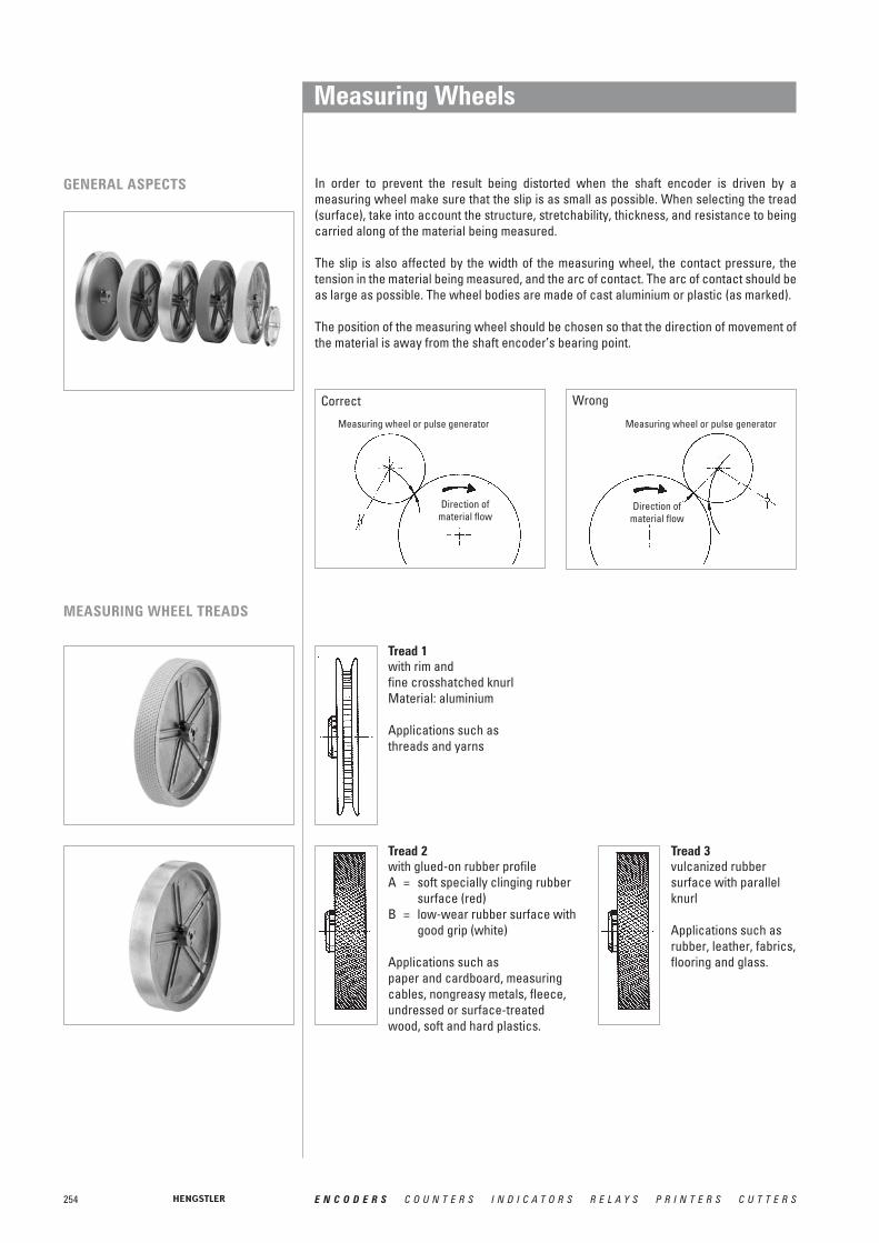
254 E N C O D E R S C O U N T E R S I N D I C A T O R S R E L A Y S P R I N T E R S C U T T E R S
Measuring Wheels
GENERAL ASPECTS In order to prevent the result being distorted when the shaft encoder is driven by a measuring wheel make sure that the slip is as small as possible. When selecting the tread(surface), take into account the structure, stretchability, thickness, and resistance to beingcarried along of the material being measured.
The slip is also affected by the width of the measuring wheel, the contact pressure, the tension in the material being measured, and the arc of contact. The arc of contact should beas large as possible. The wheel bodies are made of cast aluminium or plastic (as marked).
The position of the measuring wheel should be chosen so that the direction of movement of the material is away from the shaft encoder’s bearing point.
Correct Wrong
Measuring wheel or pulse generator
Direction ofmaterial flow
Measuring wheel or pulse generator
Direction ofmaterial flow
MEASURING WHEEL TREADS
Tread 1with rim and fine crosshatched knurlMaterial: aluminium
Applications such as threads and yarns
Tread 3vulcanized rubbersurface with parallelknurl
Applications such as rubber, leather, fabrics,flooring and glass.
Tread 2with glued-on rubber profileA = soft specially clinging rubber
surface (red)B = low-wear rubber surface with
good grip (white)
Applications such aspaper and cardboard, measuring cables, nongreasy metals, fleece, undressed or surface-treated wood, soft and hard plastics.

255E N C O D E R S C O U N T E R S I N D I C A T O R S R E L A Y S P R I N T E R S C U T T E R S
Circum- Width of Bore diameterDiameter ference Tread bearing surface
mm 4.0 mm 6.0 mm 7.0 mm 10.0 mm6.37 cm 0.2 m 1 4 0 601 014 0 601 015 0 601 017 ––
2 A 12 0 601 018 –– –– ––2 B 12 0 601 118 0 601 048 –– 0 601 0492 A 24 0 601 020 –– 0 601 092 ––2 B 24 –– –– 0 601 192 ––4 20.5 0 601 023 –– –– ––4 20 –– –– 0 601 093 ––5 16.5 0 601 026 –– 0 601 094 ––
15.92 cm 0.5 m 2 A 25 –– –– 0 601 050 ––2 B –– –– 0 601 150 0 601 1513 25 –– –– 0 601 059 0 601 1564 25 –– –– 0 601 121 1 0 601 1575 16 –– –– –– ––6 25 –– –– 0 601 063 1 0 601 1637 26.5 –– –– –– ––
5.73 cm 1/5 yd. 1 4 0 601 034 –– 0 601 037 ––2 A 24 0 601 042 –– 0 601 095 ––5 16.5 –– –– 0 601 096 ––
14.33 cm 1/2 yd. 2 A 25 –– –– –– ––4 25 –– –– 0 601 061 ––
9.70 cm 1 foot 2 A 25 –– –– 0 601 071 ––2 B 25 –– –– 0 601 171 ––4 25 –– –– 0 601 070 ––
Messräder
6.37 cm 0.2 m 1 4 0 601 100 –– –– ––15.92 cm 0.5 m 4 25 –– –– 0 601 301 ––
6 25 –– –– 0 601 300 ––
Tread 4aluminium withparallel knurl
Applications such asrubber, soft plastics, wood with rough surface, and to a limited extent for fabrics.
ORDERING DATAAluminium
Plastic
Tread 7carding belt
Applications such ascarpets and coarse fabrics.
Tread 6plastic surface
Applications such as wire, greasy metals, and steel sections.
Tread 5with rim, aluminium with parallel knurl
Applications such as threads, yarns, and bands.
1 PTB approved
Other measuring wheels available on request
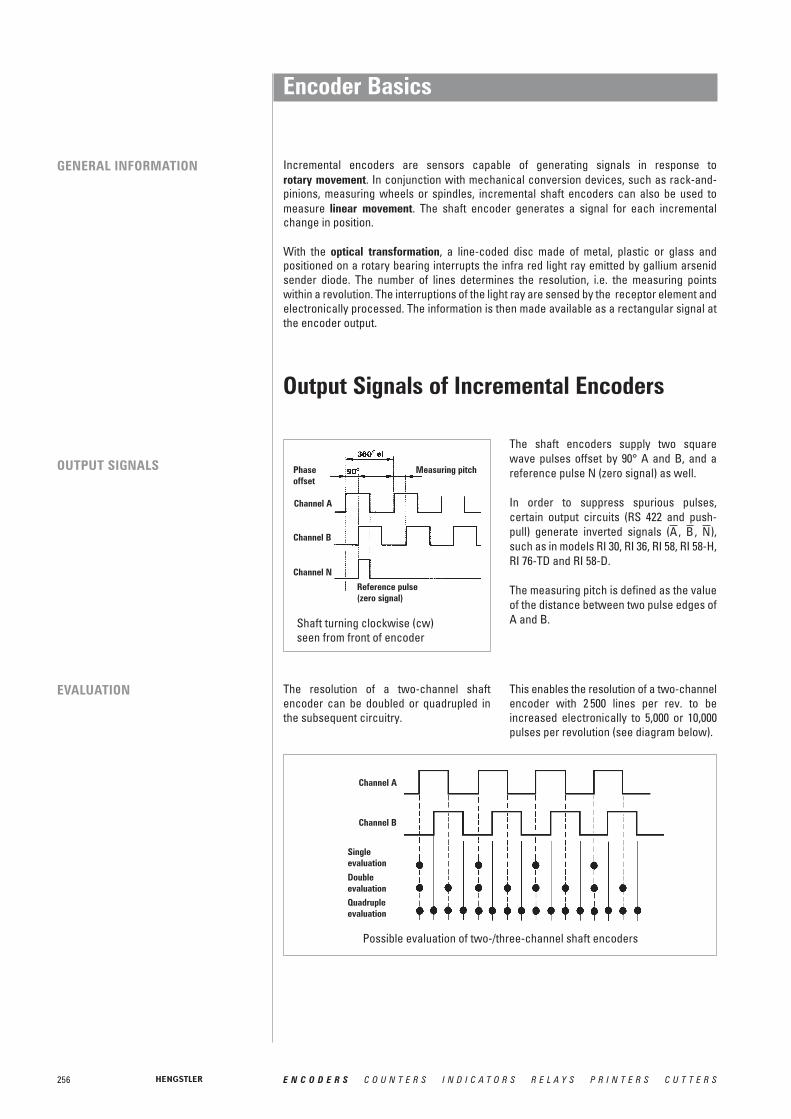
256 E N C O D E R S C O U N T E R S I N D I C A T O R S R E L A Y S P R I N T E R S C U T T E R S
Encoder Basics
Incremental encoders are sensors capable of generating signals in response to rotary movement. In conjunction with mechanical conversion devices, such as rack-and-pinions, measuring wheels or spindles, incremental shaft encoders can also be used tomeasure linear movement. The shaft encoder generates a signal for each incrementalchange in position.
With the optical transformation, a line-coded disc made of metal, plastic or glass and positioned on a rotary bearing interrupts the infra red light ray emitted by gallium arsenid sender diode. The number of lines determines the resolution, i.e. the measuring points within a revolution. The interruptions of the light ray are sensed by the receptor element andelectronically processed. The information is then made available as a rectangular signal atthe encoder output.
Phaseoffset
Channel A
Channel B
Channel N
Reference pulse(zero signal)
Shaft turning clockwise (cw)seen from front of encoder
Possible evaluation of two-/three-channel shaft encoders
Measuring pitch
The resolution of a two-channel shaft encoder can be doubled or quadrupled inthe subsequent circuitry.
EVALUATION
OUTPUT SIGNALS
The shaft encoders supply two squarewave pulses offset by 90° A and B, and areference pulse N (zero signal) as well.
In order to suppress spurious pulses, certain output circuits (RS 422 and push-pull) generate inverted signals ( , , ),such as in models RI 30, RI 36, RI 58, RI 58-H,RI 76-TD and RI 58-D.
The measuring pitch is defined as the valueof the distance between two pulse edges ofA and B.
NBA
Output Signals of Incremental Encoders
This enables the resolution of a two-channelencoder with 2 500 lines per rev. to beincreased electronically to 5,000 or 10,000pulses per revolution (see diagram below).
GENERAL INFORMATION
Channel A
Channel B
Single evaluation
Double evaluation
Quadrupleevaluation

257E N C O D E R S C O U N T E R S I N D I C A T O R S R E L A Y S P R I N T E R S C U T T E R S
Tech
nica
l Ba
sics
Encoder BasicsMaximum Speed, Protection Class
All encoders of the industrial types RI 30, RI 36, RI 58, RI 58-H, RI 58-D, RA 70-I as wellas the absolute encoders ACURO, complywith protection class IP65 according to EN60529 and IEC 529, unless otherwise stated.
These specifications are valid for the housing and the cable output and also forplugged in socket connectors. The shaftinput complies with protection class IP64. Ifhowever the encoder is mounted vertically,there must be no standing water present atthe shaft input and the ball bearings.
Maximum permissible speed as a function of number of pulses and signal frequency of shaft encoder
PROTECTION CLASS
SPEED The maximum permissible speed of a shaftencoder is derived from:
• the mechanically permissible r.p.m,• the minimum permissible pulse-edge
spacing of the square-wave output signals of the shaft encoder for the subsequent circuitry, which depends on the tolerance of the phase offset,
• the functional speed, which is limited bythe pulse frequency.
The mechanically permissible r.p.m. is specified for each shaft encoder among the mechanical characteristics.
In general, the control circuitry does notpermit less than a certain minimum edgespacing between the square-wave outputsignal pulses. The minimum pulse-edgespacing is specified for each model of shaft encoder among the electrical characteristics.
The functional speed of an encoder is obtai-ned by the equation:
n max = fmax · 103 · 60 / Z
nmax = maximum functional speed [r.p.m.]f max = maximum pulse frequency of
shaft encoder, or input frequency of downstream circuitry [kHz]
z = number of pulses of shaft encoder
In case the standard protection class IP64is not sufficient for the shaft input, e.g. with vertical mounting of the encoder, theencoders must be protected by additionallabyrinth or pot-type seals.
On request our encoders are also availablewith protection class IP67 for the shaft inputand for the housing.
RPM
Numberof pulses

258 E N C O D E R S C O U N T E R S I N D I C A T O R S R E L A Y S P R I N T E R S C U T T E R S
Encoder BasicsExamples of Flange Mounting
S = Synchro flange
Q = Square flange
Flange adapter Clamping flange
Mounting by fastening threads Mounting by angle bracket
FLANGE TYPE OVERVIEW
SHAFT ENCODERSWITH CLAMPING FLANGE
The shaft encoders with a clamping flange can be installed in following ways:• by means of various flange adapters (see “Accessories”),• by means of the clamping flange itself,• by means of the fastening threads provided on the face,• by means of an angle bracket (see Accessories”).
The encoder housing is centered by means of the clamping flange.
K = Clamping flange
R = Pilot flange

259E N C O D E R S C O U N T E R S I N D I C A T O R S R E L A Y S P R I N T E R S C U T T E R S
Encoder BasicsExamples of Flange Mounting
Mounting bell
Clamping eccentric
Angle bracketMounting by fastening threads
Mounting by fastening threads Angle bracket
SHAFT ENCODERS WITH PILOT FLANGE
SHAFT ENCODERS WITH SQUARE FLANGE
The shaft encoders with pilot flange can be installed in two ways:• by means of the fastening threads provided on the face,• by means of an angle bracket.
The encoder is centered by means of the centering collar on the flange.
The shaft encoders with square flange can be installed in two ways:• by means of the fastening threads provided on the face,• by means of an angle bracket.
The encoder is centered by means of the centering collar on the flange.
SHAFT ENCODERS WITH SYNCHRO FLANGE
The shaft encoders with synchro flange can be installed in two ways:• by means of the synchro flange and three clamping eccentrics (see “Accessories”),• by means of the fastening threads provided on the face.
The encoder is centered by means of the centering collar on the flange.

260 E N C O D E R S C O U N T E R S I N D I C A T O R S R E L A Y S P R I N T E R S C U T T E R S
Encoder BasicsExamples of Flange Mounting
SHAFT ENCODERS WITH HOLLOW SHAFT(RI 76, RI 80-E, AC110)
MOTOR SHAFT ENCODERSWITH HOLLOW SHAFT(E9, M9)
SHAFT ENCODERSWITH SOLID SHAFT
Connection of solid-shaft encoders to the shaft is by means of a coupling. The couplingcompensates for axial movements and lack of alignment between the shaft encoder and thedrive shaft, thus preventing excessive bearing loads on the encoder shaft.For further details please refer to chapter “Accessories”.
SHAFT ENCODERS WITH HOLLOW SHAFT(RI 58-D/G)
Mounting of version F, D (Clamping shaft)
1 Torque support2 Clamping ring with cross-recess screw3 Straight pin4 Actuating shaft
Mounting of version E (Blind shaft)
1 Torque support2 O-ring3 Straight pin4 Actuating shaft with threaded bore5 M4-screw with spring washer6 Cap
1. Place the base plate of encoder onto the motor rear end plate.2. Install centering tool on motor shaft to center the base plate with respect to the shaft.3. Install hardware supplied and tighten to secure the base plate. Remove centering tool.4. Position and mount the encoder housing onto the base plate with its 3x120' bayonet
snaps in their corresponding slots on the base plate. Slide the gapping shimbetween the base plate and the encoder from the side opposite the connector.
5. Place the hex wrench into the codewheel set screw. Tighten the set screw while pushing the codewheel down toward the gapping shim with the wrench.
6. Remove the gapping shim, push down and twist the encoder 30° clockwise tolock it in place.
Centering tool
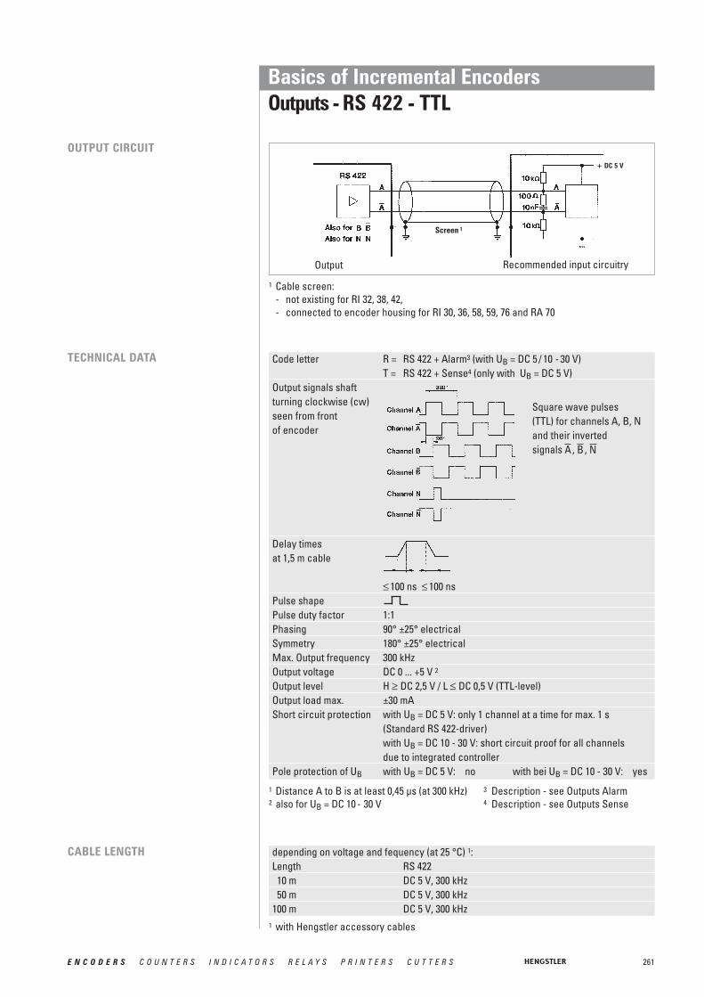
261E N C O D E R S C O U N T E R S I N D I C A T O R S R E L A Y S P R I N T E R S C U T T E R S
Basics of Incremental Encoders Outputs - RS 422 - TTL
Code letter R = RS 422 + Alarm3 (with UB = DC 5 / 10 - 30 V)T = RS 422 + Sense4 (only with UB = DC 5 V)
Output signals shaft turning clockwise (cw)seen from frontof encoder
Delay times at 1,5 m cable
≤ 100 ns ≤ 100 nsPulse shapePulse duty factor 1:1Phasing 90° ±25° electricalSymmetry 180° ±25° electricalMax. Output frequency 300 kHzOutput voltage DC 0 ... +5 V 2
Output level H ≥ DC 2,5 V / L ≤ DC 0,5 V (TTL-level)Output load max. ±30 mAShort circuit protection with UB = DC 5 V: only 1 channel at a time for max. 1 s
(Standard RS 422-driver)with UB = DC 10 - 30 V: short circuit proof for all channels due to integrated controller
Pole protection of UB with UB = DC 5 V: no with bei UB = DC 10 - 30 V: yes
OUTPUT CIRCUIT
TECHNICAL DATA
CABLE LENGTH depending on voltage and fequency (at 25 °C) 1:Length RS 42210 m DC 5 V, 300 kHz50 m DC 5 V, 300 kHz
100 m DC 5 V, 300 kHz
Output Recommended input circuitry
Square wave pulses(TTL) for channels A, B, N and their inverted signals , , NBA
1 Cable screen:- not existing for RI 32, 38, 42, - connected to encoder housing for RI 30, 36, 58, 59, 76 and RA 70
1 Distance A to B is at least 0,45 μs (at 300 kHz) 3 Description - see Outputs Alarm2 also for UB = DC 10 - 30 V 4 Description - see Outputs Sense
1 with Hengstler accessory cables
Screen 1
+ DC 5 V

262 E N C O D E R S C O U N T E R S I N D I C A T O R S R E L A Y S P R I N T E R S C U T T E R S
Basics of Incremental Encoders Outputs - Push-pull
Code letter K = push-pull, 10 mA with UB = DC 5 V or push-pull, 30 mA with UB = DC 10 - 30 VD = push-pull, 30 mA with UB = DC 5 V
Output signals shaftturning clockwise (cw) seen from frontof encoder
Delay times � ≤ 100 ns (DC 5 V, push-pull D)at 1,5 m cable � ≤ 250 ns (DC 5 V, push-pull K)
� ≤ 2 μs (DC 10 - 30 V, push-pull K)Pulse shapePulse duty factor 1:1Phasing 90° ±25° electricalSymmetry 180° ±25° electricalMax. Output frequency 300 kHz (see cable length)Output voltage 0... + UBOutput level K K D
push-pull (DC 10 - 30 V) push-pull (DC 5 V) push-pull (DC 5 V)H ≥ UB -3V H ≥ 2,5 V H ≥ 2,5 VL ≤ 2 V L ≤ 0,5 V L ≤ 0,5 V
Output load max. ±30 mA ±10 mA ±30 mAShort circuit protection all channels all channels 1 channel 2
Pole protection of UB yes yes no
OUTPUT CIRCUIT
TECHNICAL DATA
1 Cable screen:- not existing for RI 32, 38, 42 - Not connected to encoder housing for bei RI 41- Connected to encoder housing for RI 30, 36, 58, 59, 76 and RA 70
Square wave pulses(TTL or HTL) forchannels A, B, N
CABLE LENGTH depending on voltage and fequency (at 25 °C) 1:Length push-pull (K) push-pull (D) push-pull (K)
DC 5 V, 10 mA DC 5 V, 30 mA DC 10 - 30 V, 30 mA10 m 300 kHz 300 kHz DC 12 V, 200 kHz
DC 24 V, 200 kHzDC 30 V, 200 kHz
50 m 300 kHz DC 12 V, 200 kHzDC 24 V, 200 kHzDC 30 V, 100 kHz
100 m 300 kHz DC 12 V, 200 kHzDC 24 V, 100 kHzDC 30 V, 50 kHz
output Recommended input circuitry
1 Distance A to B is at least 0,45 μs (at 300 kHz)2 only 1 channel at a time for max. 1 s
1 with Hengstler accessory cables
screen 1

263E N C O D E R S C O U N T E R S I N D I C A T O R S R E L A Y S P R I N T E R S C U T T E R S
Code letter I = push-pull complementary (with UB = DC 10 - 30 V)Output signals shaft turning clockwise (cw)seen from frontof encoder
Delay times at 1,5 m cable
≤ 250 ns ≤ 250 nsPulse shapePulse duty factor 1:1Phasing 90° ±25° electricalSymmetry 180° ±25° electricalNax. output frequency 200 kHz (see cable length)Output voltage 0 ... + UBOutput level H ≥ UB -3 V / L ≤ 2 VOutput load max. ±30 mAShort circuit protection short circuit proof for all channels
due to integrated controllerPole protection of UB yes
Basics of Incremental Encoders Outputs - push-pull complementary
depending on voltage and fequency (at 25 °C) 1:Length push-pull complementary10 m DC 12 V, 200 kHz
DC 24 V, 200 kHzDC 30 V, 200 kHz
50 m DC 12 V, 200 kHzDC 24 V, 50 kHzDC 30 V, 25 kHz
100 m DC 12 V, 150 kHzDC 24 V, 25 kHzDC 30 V, 12 kHz
TECHNICAL DATA
CABLE LENGTH
1 cable screen connected with encoder housing
Square wave pulses (HTL)for channels A, B, N and their inverted signals , , NBA
1 Distance from A to B is at least 0,7 μs (at 200 kHz)
1 with Hengstler accessory cables
Screen1
OUTPUT CIRCUITDC 10 - 30 V
DC 10 - 30 V
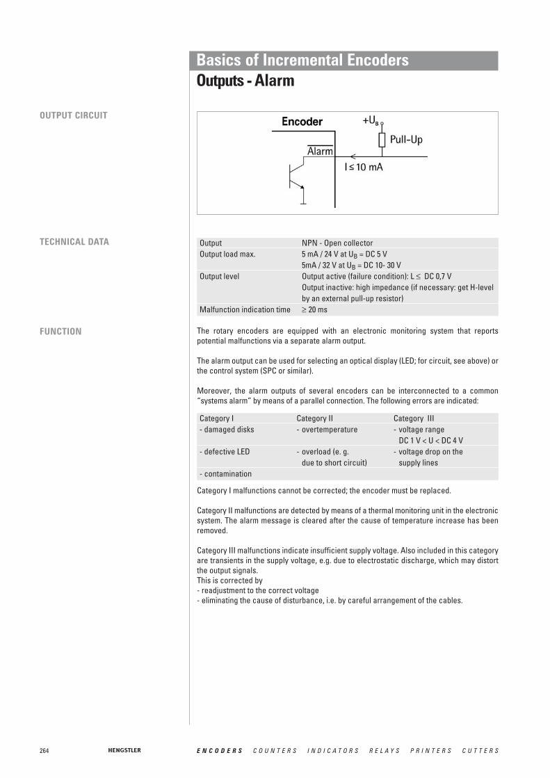
264 E N C O D E R S C O U N T E R S I N D I C A T O R S R E L A Y S P R I N T E R S C U T T E R S
Basics of Incremental Encoders Outputs - Alarm
The rotary encoders are equipped with an electronic monitoring system that reportspotential malfunctions via a separate alarm output.
The alarm output can be used for selecting an optical display (LED; for circuit, see above) orthe control system (SPC or similar).
Moreover, the alarm outputs of several encoders can be interconnected to a common“systems alarm” by means of a parallel connection. The following errors are indicated:
Category I Category II Category III- damaged disks - overtemperature - voltage range
DC 1 V < U < DC 4 V- defective LED - overload (e. g. - voltage drop on the
due to short circuit) supply lines- contamination
Output NPN - Open collectorOutput load max. 5 mA / 24 V at UB = DC 5 V
5mA / 32 V at UB = DC 10- 30 VOutput level Output active (failure condition): L ≤ DC 0,7 V
Output inactive: high impedance (if necessary: get H-level by an external pull-up resistor)
Malfunction indication time ≥ 20 ms
OUTPUT CIRCUIT
TECHNICAL DATA
FUNCTION
Category I malfunctions cannot be corrected; the encoder must be replaced.
Category II malfunctions are detected by means of a thermal monitoring unit in the electronicsystem. The alarm message is cleared after the cause of temperature increase has been removed.
Category III malfunctions indicate insufficient supply voltage. Also included in this categoryare transients in the supply voltage, e.g. due to electrostatic discharge, which may distortthe output signals. This is corrected by- readjustment to the correct voltage- eliminating the cause of disturbance, i.e. by careful arrangement of the cables.

265E N C O D E R S C O U N T E R S I N D I C A T O R S R E L A Y S P R I N T E R S C U T T E R S
Basics of Incremental Encoders Outputs - Sense at 5 V RS 422 (T)
1 Voltage drop due to long cable lengths2 Automatic readjustment of the output voltage
(only for power packs with sense input)
The sense wires enable measuring of the actual encoder supply voltage (compensates forvoltage drops due to supply current and cable resistance).Due to the voltage drop in the cables and the voltage supply, the encoder input voltage Uinis less than the power pack output voltage Uout.The present input voltage Uin is now output to the Sense VCC and Sense GND cables andreturns as data to the power pack.The input resistance Ri on the power pack should amount to at least 22 MOhm so that no voltage drop occurs on these cables.In case of power packs with sense input, it is now possible to readjust the output voltage Uoutautomatically.
OUTPUT CIRCUIT
FUNCTION

Basics of Sine-Wave Encoders
SINE-WAVE OPTOASIC TECHNOLOGYBURSTS THE LIMITS
With the introduction of the sine-waveencoder family, Hengstler has taken theopportunity to significantly rework itsOptoAsic technology.
The best features have been maintained and new improvements have been introduced. Onemajor feature that has been retained of course, is the high level of EMC reliability which wehave achieved by integrating almost the complete encoder electronics into one component.
What is new is the integrated offset and amplitude control together with the in-chip opticalsystem adjustment. In the past anybody wanting high quality, accurate sine-wave signals atlow frequencies had to trade in this for bandwidth. We are now able to meet this apparentlycontradictory requirement with our in-built amplitude control. You can't fail to be convincedby a unit which delivers sine-wave signal with harmonic distortion better than 1% at lowspeed and 500 kHz max. frequency.
The advantages are crystal clear: If you need precision at slow speeds you no longer haveto compromise your productivity because the encoder limits the maximum speed of yourmachine e.g. for tool changing processes. You can have both - accuracy and speed.
APPLICATIONS Typical applications:• Machine tools• Printing machines• Gearless elevators• Drives
GENERAL INFORMATION
266 E N C O D E R S C O U N T E R S I N D I C A T O R S R E L A Y S P R I N T E R S C U T T E R S

267E N C O D E R S C O U N T E R S I N D I C A T O R S R E L A Y S P R I N T E R S C U T T E R S
Basics of Sine-Wave EncodersSignals
THE RIS58 SIGNAL QUALITY2
1,81,61,41,2
10,80,60,40,2
020 70 120 170 220 270 320
Signal frequency [kHz]
Harm
onic
dis
torti
on (%
)
The quality of the servo loop is determined to a large extent by the absence of harmonics inthe encoder's sinewave signals, particulary at low speed. In order to achieve high interpolation factors in the sequencing control, the incremental sine signals A and B areavailable with a harmonic distortion significantly under 1% throughout the specified temperature range. This delivers excellent synchronism and a high level of positional accuracy with servo axes.
THE RIS58 SIGNALS
Signals shown at CW rotation with view on shaft's end
The incremental signals A and B and the zero signal R are differential voltage signals. Thedifferential signal level is 1 Vpp. The zero signal appears once per revolution with a peak of0.4 V and reaches its maximum value at the angle where the amplitudes of the A and B signals are equal. All signals have a DC-offset of 2.5 V.
B
A
R

268 E N C O D E R S C O U N T E R S I N D I C A T O R S R E L A Y S P R I N T E R S C U T T E R S
Basics of Absolute Encoders ACURO
ABSOLUTE ENCODERS FOLLOW THE LATEST TREND: CHANGE EASILY TO ACURO
Absolute encoders save costs and provideenhanced safety - facts that are obviouslyimportant in complex installations and multi-axis machinery: Time-consuming referenceruns after powering-up the supply voltagehave become a thing of the past for absolute encoders. Hazardous conditionscaused by reference runs (which are alwaysnecessary with incremental encoders) canbe prevented right from the start. Absoluteencoders - too large, too expensive?
A prejudice that is cleared up by ACURO.Even the multi turn version of ACURO is nolarger than most incremental encoders andcosts less than you would expect. And howabout reliability? Due to their complexity,absolute encoders seem to be susceptibleto faults. No problem with ACURO: onceinstalled they will not cause trouble, due tothe highest integration density and use ofextremely reliable technologies to ensuresafe and reliable long-term operation.
The platform concept Hengstler's new ACURO absolute encodersfeature innovative technology, simple ope-rational and optimal functional safety. Theirplatform concept also allows especiallycompact dimensions with a modular design,which always ensures the right version foreach individual application in the field ofmotor feedback and automation enginee-ring. Equipped with the new open BiSSinterface these encoders are a good andfuture oriented investment.
The mechanical construction of ACURO isrugged and precise. Double high-precisionball bearings guarantee reliable long-termoperation even at speeds of up to 12 000 rpm.ACURO is equipped with the commerciallyavailable mechanical interfaces, includingsolid shaft or hub shaft, synchro-flange orclamping flange.
ABSOLUTE ENCODERS ARE DIFFERENTIATED ACCORDING TO:
1 revolution (= 360 °) is coded in n steps.After a rotation of over 360 ° the code isrepeated.
Multiturn version
Singleturn version
Apart from measuring 360 ° (1 revolution)further coded revolutions can be recordede.g for applications in combination withlead srews or timing belts. Hengstler isusing the principle of a mechanical memory(gearbox, which is unmatched in reliabilityand EMC).

269E N C O D E R S C O U N T E R S I N D I C A T O R S R E L A Y S P R I N T E R S C U T T E R S
Basics of Absolute Encoders ACUROHigh-Tech Features in a Modular System
Of course, the user has a selection of the most advanced interface technology available:
• Tristate parallel driversThe symmetrical push-pull drivers arefully short circuit proof, overload protec-ted and polarity protected in a range from10 to 30 V.Parallel bus systems are easy to realize.So you save in cabling expenses.
• CANBus specifications according to CAN High-Speed ISO/DIS 11898 for transfer rates up to 1 MBaud.
• Suconet K1Klöckner-Moeller 2 wire fieldbus
• DeviceNet- Based on CAN layer 2 (data link layer)- Up to 64 nodes and 500 KBaud speed- Configuration via network
INNOVATIVE TECHNOLOGY
INTERFACES
APPLICATIONS
PROGRAMMABLEABSOLUTE SHAFT ENCODERS
Hengstler’s ACURO series comprises a complete range of absolute encoders, all in OPTOASIC technology. OPTOASIC unitscombine all required optical and electroniccomponents in only one silicon chip.
This new technology is tailored to the user’sneeds and offers advantages previouslyunknown in the field:- High degree of reliability
due to differential scanning and single-step Gray code.
- Fail-safe due to the elimination of more than a hundred components
- Long serviceable lifetime due to state-of-the-art semiconductor technology-
All essential parameters are userpro-grammable.Additional advantages are uncomplicatedsubsequent data processing, electronicadjustment and add-on optimization ofmechanical systems which are subject totolerances.
The new encoders are, for example, per-fectly suited to determine angular positionsin automated systems with reliable and precise operation.Absolute encoding eliminates the need fora reference run after interruptions (such aspower failures).
- High degree of electromagnetic compa-tibility due to elimination of macroscopiclow-current paths.
Our new absolute shaft encoders have anexcellent price/performance ratio. As a further feature the encoders are fully backward compatible due to identicalmounting flanges and electrical interfaces.
This makes it easy for the user to switchfrom incremental to absolute shaft encoders.
Furthermore, storage and maintenance aremore cost-efficient: the same encoder maybe used for a variety of applications andassigned to its task at the place of installa-tion.
ACURO is the right match for a wide range ofapplications - from medical technology, elevators, all printing, paper processing ormetal-processing machinery, such as presses and saws, right through to highly-dynamic drives.
• INTERBUSInterface including the potential-freepower supply is already integrated in thehousing with a diameter of only 58 mm.
• SSIThe encoders can also be supplied withsynchronous-serial interface (SSI) which is available worldwide.This allows trouble-free connection to commercial processing components.
• Profibus DPProtocol according to encoder profileclass C2 (programmable)
• BiSS- bidirectional and fully digital- synchronous serial data- licence-free- up to 8 slaves per master

270 E N C O D E R S C O U N T E R S I N D I C A T O R S R E L A Y S P R I N T E R S C U T T E R S
Basics of Absolute Encoders ACUROOpen Digitale Sensor Interface (BiSS)
GENERAL INFORMATION The bidirectional digital sensor interfaceBiSS safeguards communication betweenposition encoders or measuring devicesand industrial controls, such as a drive control, for example, and if necessary cantransmit measurement values from up to 8 sensors simultaneously.For 1 to 8 subscribers the interface masterprovides a clock signal for the simultaneouscapture of all position data and for the syn-chronous-serial data transmission which
follows on from this. Just four unidirectionalRS422 data lines are required; the slaveelectronics, kept to an absolute minimum,are incorporated on the sensor ICs. When the master sends a clock pulse online MA, the slave answers directly onreturn line SL with the recorded positiondata. Commands and parameters can beswapped on a PWM pulse form; this is,however, not necessary to start the BiSSprotocol.
Configuration Specific product developments ofindividual users are not restricted or madeunnecessarily expensive by a compulsorycompatibility.
A BiSS subscriber is described with just afew parameters and the XML-descriptivefile included with the delivery simplifiesstart up of the control system.
With each data cycle the master learns andcompensates for line delays, thus permit-ting clock rates of up to 10 Mbit/s even forcable lengths of up to 100 m. Changes in lineconditions which occur during cable drag,for example, are corrected. The precision ofsynchronization among several positionencoders along various axes is less than 1 microsecond; the master also makes thesignal delay it has recorded accessible tothe control unit, allowing further opti-mization.The BiSS protocol classifies each subscri-ber in one of the following data sections:sensor data, multi cycle data or registerdata. These data sections have varioussetups with regard to access and transmis-sion performance so that a number of diffe-rent sensor applications are catered for.Bidirectional parameter communication fordevice configuration - also applicable towhat are known as OEM parameters - is
usually consigned to the register data section. Data which alters gradually, suchas revolution counts or drive temperatures,is allocated to the multi cycle data section,with rapidly changing angle data beingassigned to the sensor data section. Control cycle times of less than 10 μs arethus not a problem, even for data words of upto 64 bits in length. There is enough room inthe protocol for redundancy; this space isnormally used to implement a CRC (cyclicredundancy check). Framed by just onestart and one stop bit, the sensor data istransmitted at the best-possible core datarate; a single multi cycle data bit is optional.Also captured when triggered, the multicycle data bits make up a second in-bandprotocol which helps to increase the effi-ciency of the sensor data; permanent moni-toring of the position and operation of thedrive is possible without interfering with thecontrol cycle.
Circuit diagram of an absolute encoder
TRANSFER SEQUENCE
BiSS connection diagram with uni-directionalconductions (one sensor, e.g. with severalslave levels)
For further information see:www.biss-interface.comi

271E N C O D E R S C O U N T E R S I N D I C A T O R S R E L A Y S P R I N T E R S C U T T E R S
Basics of Absolute Encoders ACUROSynchronous-Serial Interface (SSI)
GENERAL INFORMATION In many cases, absolute shaft encoders aresubject to severe mechanical stresses andto electrical and magnetic fields that conta-minate the site.Therefore, special design measures areneeded to combat dirt, dust and liquids inindustrial environments.Our absolute shaft encoders are of state-of-the-art rugged mechanical construction,and the electronic components are verycompact.A main consideration for immunity to inter-ference is the data transfer from the shaftencoder to the control system. The controlsystem must be able to read the readingsfrom the shaft encoder without errors.Under no circumstances should undefineddata be transmitted, for example at thechangeover point.
The major differences between the conceptof synchronous-serial data transfer forabsolute shaft encoders described hereand parallel and asynchronous serial formsof data transfer are:• less electronic components• less cabling for data transfer• the same interface hardware, regardless
of the absolute shaft encoder’s reso- lution (word length)
• electrical insulation of the shaft encoder from the control system by optocouplers
• open-circuit monitoring by constantcurrent
• data transfer rates up to 1.5 megabits per second (depending on the length of line)
• ring-register operating possible.
For correct transfer of the data a definednumber of pulses (clock pulse brush) mustbe applied to the clock input of the absoluteshaft encoder. Next, a pause TP must beobserved. As long as no clock signal isapplied to the shaft encoder, its internalparallel/serial shift register remains switched to parallel. The data change con-tinuously, corresponding to the currentposition of the shaft encoder’s shaft.
As soon as a clock pulse brush is applied tothe clock input again, the instantaneousangular data is recorded.The first shift of the clock signal from high tolow ① actuates the shaft encoder’s internalretriggerable mono-stable element, whosestorage time tm must be greater than theclock signal’s period T.The output of the monostable element con-trols the parallel/serial register via terminalP/S (parallel/serial).
70 KHz ... 1,5 MHz
Block diagramof an absolute shaft encoder
TRANSFER SEQUENCE

272 E N C O D E R S C O U N T E R S I N D I C A T O R S R E L A Y S P R I N T E R S C U T T E R S
Basics of Absolute Encoders ACUROSynchronous-Serial Interface (SSI)
With the first shift of the clock signal fromlow to high ② the most significant bit (MSB)of the angular data is applied to the shaftencoder’s serial output.With each succeeding rising edge, the nextless significant bit is shifted to the data out-put.After transmission of the least significantbit (LSB) the Alarm bit or other special bitsare transferred, depending on configura-tion. Then the data line switches to low ③until the time tm has passed.
A further transfer of data cannot be starteduntil the data line switches to high ④ again.If the clock pulse sequence is not interrup-ted at point ③, the ring-register mode isactivated automatically. This means thatthe data stored at the first clock pulse tran-sition ① are returned to the serial input Sivia the terminal SO. As long as the clockpulse is not interrupted at ③, the data canbe read out as often as wanted (multipletransfer).
T = clock pulse periodtm = storage time of monostable elementtm ranging from 10 μs to 30 μstv = 100 ns
The number of clock pulses necessary fordata transfer is independent of the reso-lution of the absolute shaft encoder.
The clock signal can be interrupted at anypoint, or continued in ring-register mode forrepeated polling.
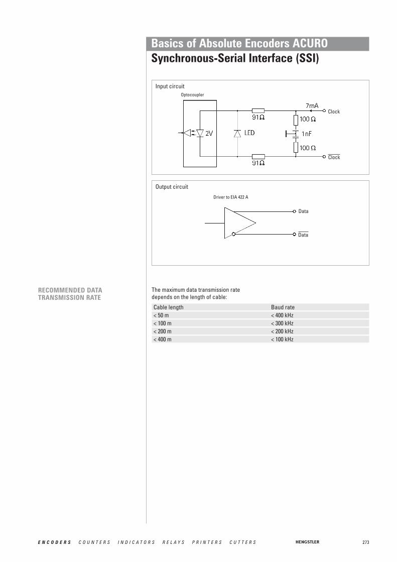
273E N C O D E R S C O U N T E R S I N D I C A T O R S R E L A Y S P R I N T E R S C U T T E R S
Basics of Absolute Encoders ACUROSynchronous-Serial Interface (SSI)
Input circuit
Output circuit
Driver to EIA 422 A
RECOMMENDED DATA TRANSMISSION RATE
Cable length Baud rate< 50 m < 400 kHz< 100 m < 300 kHz< 200 m < 200 kHz< 400 m < 100 kHz
The maximum data transmission ratedepends on the length of cable:
Optocoupler
Clock
Clock
Data
Data

274 E N C O D E R S C O U N T E R S I N D I C A T O R S R E L A Y S P R I N T E R S C U T T E R S
Basics of Absolute Encoders ACUROINTERBUS
WHAT ARE THE BENEFITS OFINTERBUS COMPARED WITH A CONVENTIONAL SYSTEMWIRING?
INTERBUS is a real-time bus for the sensor-actor-level which is able to transfer datawith a small overhead in a range of up to 4 bytes per subscriber for a maximum of 256subscribers.
It is characterized by a circular trans-mission with a fixed message frame and a central master (e.g. SPC switching-inassembly).
A summary message frame; only one message frame for all subscribers
• Lower costs for cables and wiring
• Lower noise sensitivity
• Many control signals which were analogbefore are now available as digital signals and directly transferable by INTERBUS
• Simple layout, installation and starting procedure
• High efficiency (net data rate): the percental share of the message header and of the terminating sequence decreases with a growing number of subscribers
• Data of all subscribers are stored at the same time and transferred sub-sequently
• Reaction time can easily be determined. It only depends on the system’s total extension; this is important for controlling tasks
• Constant sampling rate for reference inputs and actual values; both are trans-ferred in one bus cycle
• Considerations of priority are unnecessarysince all subscribers have the same priority
GENERAL INFORMATION
TRANSFER SEQUENCE

275E N C O D E R S C O U N T E R S I N D I C A T O R S R E L A Y S P R I N T E R S C U T T E R S
Basics of Absolute Encoders ACUROINTERBUS
ENCOM USER GROUP
• No system-parameter definition before starting procedure
• Data integrity is secured by 16-bit-CRC(according to CCITT polynomial) done for each transmission
• Sophisticated diagnostic software for the central bus controller: a point of error can specifically be isolated; in each case of malfunction there is a possibility to close the circular system in every single bus clip.
Devices with an INTERBUS interface forprocess control are now available frommore than 200 manufacturers.
Encoder manufacturers are joined togetherin the ENCOM user group; drive manu-facturers in DRIVECOM.
The user groups shall maximize the benefitfor the customer by standardization of datatransmission.
There is a high availability of devices withINTERBUS interface, and the bus mode hasalready been successful in industrial use.
The following device classes defined byENCOM are used for absolute shaft encoders:
Class 2 (K2):• 32-bit process data• Binary• Right-justified• Readable only• No control bits or status bits
Class 3 (K3):• 32-bit process data• Coded according to manufacturer
specifications• Right-justified• 7 status bits and control bits

276 E N C O D E R S C O U N T E R S I N D I C A T O R S R E L A Y S P R I N T E R S C U T T E R S
Basics of Absolute Encoders ACUROINTERBUS
TECHNICAL DATA
INTERBUS is physically divided into:
Remote bus• Voltage difference transmission RS 485• Max. cable length between two bus clips:
400 m• Max. overall cable length of remote bus:
13 km• A maximum of 64 bus clips/modules may
be directly connected to the remote bus
Peripheral bus• 5 V voltage interface• Max. overall cable length of peripheral
bus: 10 m• A maximum of 8 modules may be
connected
Installation remote bus• For modules with enclosure class IP65
(e.g. HENGSTLER absolute shaft encoders)• Voltage difference transmission RS 485• Max. overall cable length: 50 m• Connection via bus clip or passive
T-manifold• Each subscriber has an electrically
isolated voltage transformer• 24 V supply may be led via the bus line or
be connected to the T-manifold• 8 modules may be connected.
The transmission speed is 500 kBit/s.

277E N C O D E R S C O U N T E R S I N D I C A T O R S R E L A Y S P R I N T E R S C U T T E R S
Basics of Absolute Encoders ACUROINTERBUS
INTERBUS DIAGNOSTIC CONCEPT
The diagnostic system is able to indicateperipheral and controller errors beside theselection of faults. Due to a row of LEDscomprising 16 bits, available on most swit-ching-in assemblies, decentralized processstates can be displayed centrally.
• Status display on control system for inputs and outputs without hand pro-gramming unit
• Self-acting fault detection and display with point and type of error without user programming
• Usual diagnosis by hand programming unit can be kept
• Diagnostic representation is always the same regardless of the control system.
Switching-in assembly
Display: Mode of operation
Display: Error typeError on switching-in assembly Defective remote busDefective peripheral busError on moduleParameter for error type
For further information see:www.interbusclub.com\dei
Switching-in assembly readyCLAB signal of SPC activeINTERBUS runningBus segments off
278 E N C O D E R S C O U N T E R S I N D I C A T O R S R E L A Y S P R I N T E R S C U T T E R S
Basics of Absolute Encoders ACUROCANopen
GENERAL INFORMATION
FIELD OF APPLICATION
The AC 58 is an absolute shaft encoder(encoder, angle encoder). The versiondescribed in this technical manual sends itscurrent position to another station via the"CAN-bus" transmission medium (physi-cally: screened and twisted two-wire line).
The serial bus system CAN (Controller AreaNetwork), which had been originally deve-loped by Bosch/ Intel for automotive uses,is gaining ground in industrial automationtechnology. The system is multimaster-compatible, i.e. several CAN- stations areable to request the bus at the same time.The message with the highest priority(determined by the identifier) will be receivedimmediately.
The data transfer is regulated by the mes-sage's priority. Within the CAN system,there are no transport addresses, but mes-sage identifiers. The message which isbeing sent can be received by all stations atthe same time (broadcast).
By means of a special filter methods, thestation only accepts the relevant messa-ges. The identifier transmitted with themessage is the basis for the decision as towhether the message will be accepted ornot.
The bus coupler is standardised according tothe international standard ISO-DIS 11898(CAN High Speed) standard and allows datato be transferred at a maximum rate of 1MBit/ s. The most significant feature of theCAN-protocol is its high level of transmis-sion reliability (Hamming distance = 6).
The CAN-Controller Intel 82527 used in the encoder is basic as well as full-CANcompatible and supports the CAN-specifi-cation 2.0 part B (standard protocol with11-bit- identifier as well as extended proto-col with 29-bit identifier). Up to now, only 11-bit identifiers have been used for CANopen.
In systems, where the position of a drive orof any other part of a machine has to berecorded and signalled to the controlsystem, the AC 58 can assume this function.The AC 58 can resolve, for instance, positio-ning tasks by sending the check-back signal concerning the present drive position via the CAN bus to the positioningunit.

279E N C O D E R S C O U N T E R S I N D I C A T O R S R E L A Y S P R I N T E R S C U T T E R S
Basics of Absolute Encoders ACUROCANopen
CANOPEN COMMUNICATIONMODEL AND PROFILE
For the following devices, profiles already exist::• CiA Draft Standard Proposal 401 for Input/Output Modules• CiA Draft Standard Proposal 402 for Drives and Motion Control• CiA Work Item 403 for Human-Machine Interfaces• CiA Work Draft 404 for Closed-Loop Controllers and Transformers• CiA Work Item 405 for IEC-1131 Interfaces• CiA Draft Standard Proposal 406 for Encoders• CiA Work Item 407 for Public Transport• CiA Work Item 408 for Fork-Lifts
Layer 1 (Physical Layer): ISO-DIS 11898 (CAN High Speed)
Layer 2 (Data Link Layer): ISO-DIS 11898 (CAN High Speed)
Layer 7 (Application Layer): CiA DS 301 (CANopen CAL-based Communication Profile)+ Device profile CiA DS 4xx (CANopen Device Profile for xx)

280 E N C O D E R S C O U N T E R S I N D I C A T O R S R E L A Y S P R I N T E R S C U T T E R S
Basics of Absolute Encoders ACUROCANopen
THE CANOPEN PROFILE
THE ENCODER DEVICE PROFILE(CIA DSP 406)
About two and a half years after the CiA, theassociation of the user and manufacturer ofCAN products, had adopted the CANApplication Layer (CAL), CANopen and therespective device profiles paved the wayfor the development of open systems.CANopen has been developed under thetechnical direction of the SteinbeisTransfer Centre for Automation (STAReutlingen; Germany) on the basis of thelayer 7 CAL specification.Compared with CAL, CANopen only provi-des the functions needed for this specialpurpose. CANopen is thus a part of CALwhich has been optimised for applicationpurposes and allows for a simpler systemstructure as well as for simpler devices.CANopen has been optimised for a quicktransfer of data in real-time systems andhas been standardised for different deviceprofiles.The CAN in Automation (CiA) association ofusers and manufacturers is responsible forthe establishing and the standardisation ofthe respective profiles.
The RA58 with CANopen meets the require-ments laid down in the communication pro-file (CiA DS 301) and in the device profile forencoders.
CANopen allows for:• auto configuration of the network,• comfortable access to all device
parameters.• synchronisation of the devices,• cyclical and event-controlled process
data processing,• simultaneous data input and output.
CANopen uses four communication objects(COB) with different features:• Process Data Objects (PDO) for
real-time data• Service Data Objects (SDO) for the
transfer of parameters and programs• Network Management (NMT,
Life-Guarding)• predefined objects (for synchronisation,
time stamp, emergency message)
All device parameters are stored in anobject directory. The object directory contains the description, data type andstructure of the parameters as well as theiraddresses (index).The directory consists of three parts: com-munication profile parameters, device pro-file parameters and manufacturer specificparameters.
This profile describes a binding, but manu-facturer-independent definition of the inter-face for encoders. The profile not only defi-nes which CANopen functions are to beused, but also how they are to be used. Thisstandard permits an open and manufactu-rer-independent bus system.
The device profile consists of two objectcategories• the standard category C1 describes all
the basic functions the shaft encoder must contain
• the extended category C2 contains a variety of additional functions which either have to be supported by category C2 shaft encoders (mandatory) or which are optional. Category C2 devices thus contain all C1 and C2 mandatory functions as wellas, depending on the manufacturer, further optional functions.
Furthermore, an addressable area is defined in the profile, to which, dependingon the manufacturer, different functionscan be assigned.

281E N C O D E R S C O U N T E R S I N D I C A T O R S R E L A Y S P R I N T E R S C U T T E R S
Basics of Absolute Encoders ACUROCANopen
DATA TRANSFER
COB IDENTIFIER
NODE NUMBER
In CANopen, the data is transferred bymeans of two different communicationtypes (COB = Communication Object) withdifferent features:
• Process Data Objects (PDO)• Service Data Objects (SDO)
The priority of the message objects is deter-mined by the COB identifier.
The process data objects (PDO) serve thehighly dynamic exchange of real-time data(e.g. position of the shaft encoder) with amaximum length of 8 Byte. This data istransferred with high priority (low COBidentifier). PDOs are broadcast messagesand put their information simultaneously atthe disposal of all desired receivers.
The service data objects (SDO) form thecommunication channel for the transfer ofdevice parameters (e.g. programming of theshaft encoders' resolution). Since theseparameters are transferred acyclically (e.g.only once when running up the network),the SDO objects have a low priority (highCOB identifier).
For an easier administration of the identifiers, CANopen uses the "Predefined master/SlaveConnection Set"). In this case, all identifiers with standard values are defined in the objectdirectory. However, these identifiers can be modified according to the customers' needs viaSDO access.
The 11-bit identifier consists of a 4 Bit function code and a 7 Bit node number.
Bit-No. 10 9 8 7 6 5 4 3 2 1 0Type Function code Node numberAssignment 1 x x x x 0 0 x x x x x
1 x = binary value can be selected freely 0 or 1); 0 = 0 value is fixed
The higher the value of the COB identifier, the lower the identifier’s priority!
The 7-bit node number is set by means of the hardware via the 5 DIP switches on the encoder’s back.
For further information see CAN user organisation:www.can-cia.dei

282 E N C O D E R S C O U N T E R S I N D I C A T O R S R E L A Y S P R I N T E R S C U T T E R S
Basics of Absolute Encoders ACURODeviceNet
Background• The basic technology was developed by
Allen-Bradley• Introduced in March 1994• The ODVA (Open DeviceNet Vendor
Association) was founded in April 1995
Technology• CAN-Layer 2 (Data Link Layer) - ISO 11898
and 11519-1• DeviceNet covers layer 7 (Application
Layer) and layer 1 (Physical Layer), developed for industrial automation
DC 24 V power and the signals for alldevices are carried on one cable
notenNode notenNode
notenNode notenNode
notenNodenotenNodenotenNode
notenNode
notenNode
Spur line length: 0 ... 6 m
Main benefits• Reduced cabling and installation effort• Reduced run-in time• Reduced down-time• Fast error elimination• Devices can be removed, replaced and
inserted without having to shut the network down
• Devices from various manufacturers can be exchanged
• Devices are configured over the network
NETWORK SPECIFICATION
Maximum devices64 nodes per network
Device ConnectionsT-TapsZero-drop
Physical media(Shielded Twisted Pair)Communications and Power• Thick - Trunk wire• Thin - Trunk or Drop
CumulativeDrop-line Budget156m @ 125KBaud
78m @ 250KBaud39m @ 500KBaud
(Maximum of 6m each)
Drop-line wiring•Single drop•Daisy-chaining off drop•Branching off drop
Terminating Resistors121Ω Resistors at bothnetwork trunkline ends
BACKGROUND ANDTECHNOLOGY
LINEAR BUS TOPOLOGY
Network Power• DC 24 V power to devices• Thick trunk rated to 8 amps• Thin wire rated at 3 amps
Messaging ServicesProducer/Consumer•High-speed I/O•Programming•Configuration•Diagnostics
Trunk line Distance and Baud rate100m Max. with Thin cable500m @ 125Kbaud (thick)250m @ 250Kbaud (thick)100m @ 500Kbaud (thick)(4 Km with Repeaters)
For more information about deviceNet please contact:http://www.odva.orge-mail: [email protected]

283E N C O D E R S C O U N T E R S I N D I C A T O R S R E L A Y S P R I N T E R S C U T T E R S
Basics of Absolute Encoders ACUROProfibus-DP
GENERAL INFORMATION The basic functions of the PROFIBUS DP are here only described in extracts. Foradditional information, please refer to thestandards on PROFIBUS DP, i.e. DIN 19245-3 and EN 50170 respectively.
INTRODUCTION The AC 58 is an absolute shaft encoder(encoder, angle encoder). The versiondescribed in this manual sends its currentposition to another station via the transmis-sion medium "PROFIBUS DP" (physically:screened and twisted pair line). The AC 58supports all class 1 and 2 functions listed inthe encoder profile.
PROFIBUS-DP is manufacturer indepen-dent, open field bus standard for a variety ofapplications in the field of production, pro-cess and building services automation. Therequirements of openness and indepen-dence from the manufacturer are stipulatedin the European standard EN 50 170.
PROFIBUS-DP permits the communicationof devices produced by different manufac-turers without any particular adaptations ofthe interfaces.PROFIBUS DP is a special standard versionfor a quick data exchange within the fieldlevel which has been optimised in terms ofspeed and low connection costs. Centralcontrol systems like, for example SPC/ PCcommunicate via a quick, serial connectionwith local field devices like drives, valves,or encoders. The data exchange betweenthese devices is predominantly cyclical.The communication functions required forthis exchange are determined by the basicfunctions of the PROFIBUS DP according tothe EN 50 170 European standard.
FIELD OF APPLICATION In systems, where the position of a drive orof any other part of a machine has to berecorded and signalled to the controlsystem, the AC 58 can assume this function.
The AC 58 can resolve, for instance, positio-ning tasks by sending the checkback signalconcerning the present drive position viathe PROFIBUS DP to the positioning unit.
BASIC FUNCTIONS OF THE PROFIBUS-DP
The central control system (master) cycli-cally reads out the input information fromthe slaves and writes the output informationto the slaves. For this purpose, the buscycle time has to be shorter than the program cycle time of the central SPC,which amounts to approx. 10 ms for variousapplications.
Apart from the cyclical user data transfer,the PROFIBUS DP version also disposes ofpowerful functions for diagnosis and initialoperation procedures. The data traffic iscontrolled by watchdog functions on boththe slave and the master side. The followingtable summarises the basic functions of thePROFIBUS DP.

284 E N C O D E R S C O U N T E R S I N D I C A T O R S R E L A Y S P R I N T E R S C U T T E R S
Basics of Absolute Encoders ACUROProfibus-DP
Transmission technology: • RS-485 twisted pair line• Baud rates ranging from 9.6 kBit/s up to 12 MBit/s
Bus access: • Token passing procedure between the masters andmaster-slave procedures for slaves
• Monomaster or multimaster systems possible• master and slave devices, max. of 126 stations at a
single busCommunication: • Point-to-point (user data communication) or multicast
(control commands)• cyclical master-slave user data communication and
acyclical master-master data transferOperating state: • Operate: cyclical transfer of input and output data
• Clear: The input data are read, the output data remainin the safe status
• Stop: only master-master data transfer is possibleSynchronisation: • Control commands enable a synchronisation of the input
and output data• Sync mode: Output data are being synchronised
Functionality: • Cyclical user data transfer between DP master and DPslave(s)
• Single DP slaves are dynamically activated or deactivated• Control of the DP slave's configuration. Powerful
diagnostic functions, 3 stepped diagnostic message levels.• Synchronisation of in- and/ or output• Address assignment for the DP slaves via the bus• Configuration of the DP masters (DPM1) via the bus• Maximum of 246 byte input and output data per DP slave
possibleProtection functions: • All messages are transferred with a hamming distance
of HD=4• Response control at the DP slaves• Access protection of the DP slaves' input/ output• Monitoring of the user data communication with
adjustable control timer at the masterDevice types: • DP master class 2 (DPM2), e.g. programming/ project
planning devices• DP master class 1 (DPM1), e.g. central automation devices
like SPC, PC• DP slave e. g. devices with binary or analogue input/
output, drives, valves
ESSENTIALFEATURES/SPEED
The PROFIBUS DP only requires approx.1 ms at a speed of 12 MBit/s in order totransfer 512 Bit input and 512 Bit output databy means of 32 stations. The following diagram shows the usualPROFIBUS DP transfer time interval in rela-tion to the number of stations as well as thetransmission speed. The high speed can beabove all explained by the fact that the inputand output data within a message cycle aretransferred by using the layer 2 SRD service(Send and Receive Data Service).
Diagnostic function: The comprehensive diagnostic functions ofPROFIBUS DP allow a quick localisation ofthe errors. The diagnostic messages aretransferred by means of the bus and areassembled at the master. They are subdivi-ded in three levels:
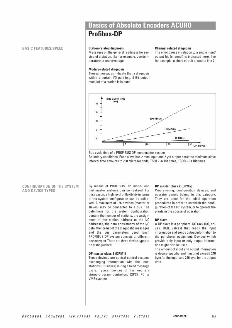
285E N C O D E R S C O U N T E R S I N D I C A T O R S R E L A Y S P R I N T E R S C U T T E R S
Basics of Absolute Encoders ACUROProfibus-DP
BASIC FEATURES/SPEED
CONFIGURATION OF THE SYSTEMAND DEVICE TYPES
By means of PROFIBUS DP, mono- andmulitmaster systems can be realised. Forthis reason, a high level of flexibility in termsof the system configuration can be achie-ved. A maximum of 126 devices (master orslaves) may be connected to a bus. Thedefinitions for the system configurationcontain the number of stations, the assign-ment of the station address to the I/Oaddresses, the data consistency of the I/Odata, the format of the diagnostic messagesand the bus parameters used. Each PROFIBUS DP system consists of differentdevice types. There are three device types tobe distinguished:
DP master class 1 (DPM1)These devices are central control systemsexchanging information with the local stations (DP slaves) during a fixed messagecycle. Typical devices of this kind are stored-program controllers (SPC), PC orVME systems.
DP master class 2 (DPM2)Programming, configuration devices, andoperator panels belong to this category.They are used for the initial operation procedures in order to establish the confi-guration of the DP system, or to operate theplants in the course of operation.
DP slaveA DP slave is a peripheral I/O rack (I/O, dri-ves, HMI, valves) that reads the input information and sends output information tothe peripheral equipment. Devices which provide only input or only output informa-tion might also be used.The amount of input and output informationis device specific and must not exceed 246byte for the input and 246 byte for the outputdata.
Station-related diagnosisMessages on the general readiness for ser-vice of a station, like for example, overtem-perature or undervoltage.
Module-related diagnosisTheses messages indicate that a diagnosiswithin a certain I/O part (e.g. 8 Bit outputmodule) of a station is in hand.
Channel related diagnosisThe error cause in relation to a single input/output bit (channel) is indicated here, likefor example, a short-circuit at output line 7.
Bus cycle time of a PROFIBUS DP monomaster systemBoundary conditions: Each slave has 2 byte input and 2 yte output data; the minimum slaveinterval time amounts to 200 microseconds; TSDI = 37 Bit times, TSDR = 11 Bit times

286 E N C O D E R S C O U N T E R S I N D I C A T O R S R E L A Y S P R I N T E R S C U T T E R S
Basics of Absolute Encoders ACUROProfibus-DP
PROFIBUS DP monomaster system
In the case of monomaster bus systems,there is only one master active at busduring the on-line phase of the bus system.The above diagram shows the system con-figuration of a monomaster system. The SPC based control system is the central control element. By means of thetransmission medium, the DP slaves arelocally linked to the SPC control system. Byusing this system configuration, the shortest bus cycle time can be obtained.
PROFIBUS-DP Multi-Master System
In the multimaster mode, several mastersare linked to a single bus. They either formindependent subsystems consisting of oneDPM1 and its corresponding DP slaveseach, or additional configuration and diagnostic devices (see diagram below).The I/O maps of the DP slaves can be readby all DP masters, but only one DP master,the one which has been assigned DPM1during project planning, is able to write theoutput information. Multimaster systemsattain a medium bus cycle time.
DP-Master (Class 1)
decentral inputs and outputs
decentral inputs and outputs decentral inputs and outputs
several masters can read the data of the DP slaves
287E N C O D E R S C O U N T E R S I N D I C A T O R S R E L A Y S P R I N T E R S C U T T E R S
Basics of Absolute Encoders ACUROProfibus-DP
SYSTEM PERFORMANCE In order to obtain a high level of exchange-ability between the devices, the systemperformance of PROFIBUS DP has alsobeen standardised. It is mainly determinedby the operational status of the DPM1.
The DPM1 can either be controlled locallyor via the bus by the project planningdevice. The following three main states canbe distinguished:
StopThere is no data traffic between DPM1 andthe DP slaves.
ClearThe DPM1 reads the input information ofthe DP slaves and maintains the safe statusof the DP slaves' output.
OperateThe DPM1 has entered the data transferphase. In case of a cyclical data traffic, theinput is read by the DP slaves while the out-put is transferred to the DP slaves.
After an error has occurred during the datatransfer phase of the DPM1, like for example,the failure of a DP slave, the response of thesystem is determined by the operatingparameter "Auto Clear".
If this parameter has been set to true, theDPM1 will set the output of all the respec-tive DP slaves to the safe status, as soon asa DP slave is no longer available for userdata communication. Afterwards, theDPM1 changes to the clear status.
If this parameter is = false, the DPM1remains, even if an error occurs, in the ope-rate status, and the user can determine theresponse of the system at his own discre-tion.
CYCLICAL DATA TRANSFER BETWEEN DPM1 AND THE DP SLAVES
The data traffic between the DPM1 and therespective DP slaves is automatically hand-led by the DPM1 in a fixed, recurring order.When configuring the bus system, the userassigns a DP slave to the DPM1. In addition,the slaves to be included in- or excludedfrom the user data communication are defi-ned.
The data traffic between the DPM1 and theDP slaves is subdivided in parametrisation,configuration, and data transfer phases.Before including a DP slave in the datatransfer phase, the DPM1 checks during theparametrisation and configuration phase,whether the planned set configuration corresponds to the actual configuration ofthe device.
For this check, the device type, the informa-tion on the format and the length as well asthe number of input and output lines have tobe correct. The user thus obtains a reliableprotection against parametrisation errors.In addition to the user communication,which is automatically executed by theDPM1, the user may request the new parametrisation data to be sent to the DPslaves.

288 E N C O D E R S C O U N T E R S I N D I C A T O R S R E L A Y S P R I N T E R S C U T T E R S
Basics of Absolute Encoders ACUROProfibus-DP
DATA TRAFFIC BETWEEN DPM1AND PROJECT PLANNING DEVICES
Function Meaning DPM1 DPM2Get_master_Diag reads the diagnostic data of the DPM1 M O
or the collective diagnosis of the DPslaves.
Download / Upload Group reads or writes the entire configuration O O(Start_Seq, Down- / data of a DPM1 and of the respectiveUpload, End_Seq) DP slaves.Act_Para_Brct activates the bus parameters for all O O
operating DPM1 devices.Act_Param activates parameters or modifies the O O
operating status of the operatingDPM1 device.
In addition to the functions between DP master and DP slaves, master-mastercommunication functions are available, seetable. They support the project planningand diagnostic devices in projecting thesystem via the bus.
Besides the upload and download functions, the master-master functionsoffer the opportunity to switch the user datatransfer between the DPM1 and the singleDP slaves dynamically on or off as well as tomodify the operating status of the DPM1.
User data communication for PROFIBUS-DP
M: mandatory, O: optionalFunctional overview for the master-master functions for PROFIBUS DP

289E N C O D E R S C O U N T E R S I N D I C A T O R S R E L A Y S P R I N T E R S C U T T E R S
Basics of Absolute Encoders ACUROProfibus-DP
SYNC MODE In addition to the station-related user datacommunication being automatically hand-led by the DPM1, the masters may sendcontrol commands to a single slave, a groupof slaves or all slaves at the same time.These control commands are transferredas multicast. It is only by means of this multicast that the sync and freeze operatingmodes for the event-controlled synchroni-sation of the DP slaves have been enabled.
The sync mode is started by the slaves, assoon as they receive a sync command formthe respective master. The output lines ofthe addressed slaves will then be frozen intheir current state. The output data will bestored at the slaves during the followinguser data transfers; the state of the outputlines, however, will remain unchanged.Unless the next sync command has beenreceived, the stored output data will not beconnected to the output lines. By selectingunsync, the sync mode is terminated.
PROTECTIVE MECHANISMS For reasons of safety, it is necessary toequip PROFIBUS DP with powerful protect-ive functions against false parametrisationor failure of the transmission equipment.For this purpose, control mechanisms at the DP master and the DP slave have been realised, taking the form of time-out cir-cuits. The monitoring interval is determinedduring project planning.
At the DP masterThe DPM1 controls the data traffic of theslaves by means of the Data_Control_Timer.For each slave, a special timer is used. Thetime-out circuit will respond, if no properuser data transfer occurs during a controlinterval. In this case, the user will be infor-med. If the automatic response to an error(Auto_Clear = True) has been released, theDPM1 will quit the operate status, switchthe output lines of the respective slaves tothe safe status and change to the clear status.
At the DP slaveIn order to recognise errors by the masteror transmission errors, the slave executesthe response control. If there is no data traf-fic during the response control interval, theslave will automatically switch the outputlines to the safe status. When operating in multimaster systems, asupplementary access protection for theI/O lines of the slaves will be necessary.This is to make sure that direct access canonly be gained by an authorised master. Forall the other masters, the slaves will providean I/O map which can be also be read with-out access authorisation.
COMMUNICATIONINTERFACE
The communication interface correpondsto the PROFIBUS DP class 2 encoder profile.
Within this interface the class 1 functionsare included.
For further information see:www.profibus.dei
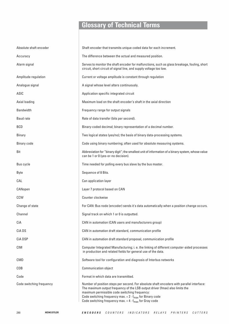
290 E N C O D E R S C O U N T E R S I N D I C A T O R S R E L A Y S P R I N T E R S C U T T E R S
Glossary of Technical Terms
Absolute shaft encoder Shaft encoder that transmits unique coded data for each increment.
Accuracy The difference between the actual and measured position.
Alarm signal Serves to monitor the shaft encoder for malfunctions, such as glass breakage, fouling, short circuit, short circuit of signal line, and supply voltage too low.
Amplitude regulation Current or voltage amplitude is constant through regulation
Analogue signal A signal whose level alters continuously.
ASIC Application specific integrated circuit
Axial loading Maximum load on the shaft encoder‘s shaft in the axial direction
Bandwidth Frequency range for output signals
Baud rate Rate of data transfer (bits per second).
BCD Binary-coded decimal; binary representation of a decimal number.
Binary Two logical states (yes/no); the basis of binary data-processing systems.
Binary code Code using binary numbering; often used for absolute measuring systems.
Bit Abbreviation for “binary digit“; the smallest unit of information of a binary system, whose value can be 1 or 0 (yes-or-no decision).
Bus cycle Time needed for polling every bus slave by the bus master.
Byte Sequence of 8 Bits.
CAL Can application layer
CANopen Layer 7 protocol based on CAN
CCW Counter clockwise
Change of state For CAN: Bus node (encoder) sends it's data automatically when a position change occurs.
Channel Signal track on which 1 or 0 is outputted.
CiA CAN in automation (CAN users and manufacturers group)
CiA DS CAN in automation draft standard, communication profile
CiA DSP CAN in automation draft standard proposal, communication profile
CIM Computer Integrated Manufacturing; i. e. the linking of different computer-aided processesin production and related fields for general use of the data.
CMD Software tool for configuration and diagnosis of Interbus networks
COB Communication object
Code Format in which data are transmitted.
Code switching frequency Number of position steps per second. For absolute shaft encoders with parallel interface:The maximum output frequency of the LSB output driver (fmax) also limits the maximum permissible code switching frequency:Code switching frequency max. = 2 · fmax for Binary codeCode switching frequency max. = 4 · fmax for Gray code

291E N C O D E R S C O U N T E R S I N D I C A T O R S R E L A Y S P R I N T E R S C U T T E R S
Glossary of Technical Terms
Coefficient of thermal expansion Material expansion under influence of temperature change [μm/°K m], relevant for linearscales.
Complementary Output circuit for which also the inverted signals are outputted (e.g. Channel A and Channel A). Electrically, the 1/0 levels are transmitted as voltage differences between two lines. In this way the information signal (the difference) remains pure as in general interferences are interspersed equally on both lines.
CRC Cyclic redundancy check. Bit error protection method for data communication.
CW Clockwise
Data bus System of lines over which data are transferred electronically in parallel or serially.
Data consistency Intrinsic coherence of data in respect of timing and logical aspects.
Data integrity Correspondence of data with the reality that they describe.
Datavalid Output for checking the validity of data.
DC Direct current (not alternating)
Demodulator Device that filters the original information out of an altered signal again.
DeviceNet - conformity Confirmation of agreement of a bus node with the DeviceNet specifications and correctand interoperability interoperability with other DeviceNet nodes.
Differential line driver Output circuit in which the difference between the two signals A and A is evaluated, thus providing high signal transmission reliability.
DIN Deutsche Industrie Norm (German Industrial Standard)
Direction Control input for determining the data sequence (whether ascending for clockwise or counterclockwise rotation).
Dual Code Natural binary code
EDS - File Electronic data sheet. This is a file with the device specific parameter description and is provided by the manufacturer of a DeviceNet or CANopen device.
EEPROM “Electrically Erasable Programmable Read-Only Memory“ chip (see EPROM).
EIA Electonic Industries Association; U.S. umbrella organization of manufacturers of electronic equipment and facilities. It is responsible for maintenance and development of the industrial standards for interfaces between data-processing devices and data communications equipment.
EMC Electromagnetic compatibility
ENCOM User group of manufacturers of INTERBUS-S absolute shaft encoders
Encoder monitoring See “Alarm signal”
Enable Control input via which the data outputs can be activated.
Encoder power Supply voltage to be provided for the shaft encoder.
EPROM “Erasable Programmable Read-Only Memory” chip, which can be erased with ultraviolet light, after which new data can be written into it.
Gray code A special binary code that changes only one data bit per measuring step at a time. It is used with absolute encoders.

292 E N C O D E R S C O U N T E R S I N D I C A T O R S R E L A Y S P R I N T E R S C U T T E R S
Glossary of Technical Terms
Hamming distance Measure for data security in a data transmission. The higher the number the better the ability to detect data errors.
Harmonic Distortion Measure for the signal quality of sinewave encoder [%]. It describes the content of harmonics in analogue signals. The lower the number the better the signal.
Hysteresis error Measurement deviation for a position approached from opposite directions.
Identifier Address of a message in a CAN network.
IEC International Electrotechnical Commission; organization promoting international standar-dization of electrical components.
Immunity to interference Test procedure according to IEC 801, Part 4– A test of susceptibility to fast electrical transients (bursts) causing interference on lines.
The test values are divided into 5 levels:Level Mains line Data and control lines1 0.5 kV 0.25 kV2 1.0 kV 0.5 kV3 2.0 kV 1.0 kV4 4.0 kV 2.0 kVX special special
– Test procedure according to IEC 801, Part 2Discharge of static electricity on the surface and in the surroundings of the specimen.The test values are divided into 4 classes:
Class test voltage1 2 kV2 4 kV3 8 kV4 15 kV
– Radio interference voltage test to VDE 0871.
Incremental measuring system Measuring method in which the variable is formed by counting increments (measuring steps).
Incremental shaft encoder Shaft encoder which transmits an electrical signal (yes/no) for each increment, determined by the marked disc.
Integer Integral values; range of values at n bit: 0 … (2n-1)
Integrated coupling Flexible coupling built into shaft encoders
INTERBUS Real time bus for the sensor-actor-level
Interbus-Loop Two wire version of Interbus, transmitting data over the power supply lines and using Phoenix Contact "Quickon" cable plugs.
Interface Transfer point with certain terminals, signals, or signal sequences. The interface serves for communication of the shaft encoder with other systems.
Interpolation Scanning of a sinewave signal to increase resolution by generating intermediate position values.
IP See “Protection class”
Jitter Change in the phase angle between Channel A and B within one revolution (360°).
Latch Control input for storing (“freezing”) the data before they are read out.

293E N C O D E R S C O U N T E R S I N D I C A T O R S R E L A Y S P R I N T E R S C U T T E R S
Glossary of Technical Terms
Linearity Deviation of the reading from the actual value within one revolution (360°).
Line driver Output circuit that makes a larger current possible.
LSB Least Significant Bit
Measuring wheel A wheel that, mounted on a shaft encoder, converts a linear motion into a rotary motion.
MSB Most Significant Bit
MTBF “Mean Time Between Failures”, a measure of average service life.
Multi-turn shaft encoder Shaft encoder which transmits the number of shaft revolutions as well as the angular position of the shaft.
NC machinery Numerically Controlled machinery; their movements are programmed.
NPN input/output Transistor input/output circuit implemented with an npn transistor, and thus negative switching.
Offset For programmable absolute shaft encoders: the offset value is added to the value of physical position. As a result you get a relative shift of the output value (output value = position value + offset value).
Parallel interface Transfer point at which the data are transferred in parallel over several lines.
Parity Checkbit for error detection in data transfer
PDO Process data object (in CAN networks)
P.L.C. Programmable Logic Controller: control system whose program is stored in a program memory and can be changed.
Phase discriminator Sense-of-direction detector that functions by evaluating the phase angle between Signal A and Signal B.
Phase tolerance Deviation of the pulse-edge from Channel A to B, relative to the phase angle 90°.
PNP input/output Transistor input/output circuit implemented with a pnp transistor, and thus positive switching.
Preset For programmable absolute shaft encoders: The programmed numerical value is accepted as output value (output value = preset value).
Protection class The enclosure class is designated according to DIN 40050, by IP and a two-figure codenumber.1st digit Degree of protection against ingress of solid bodies:
0 no special protection1 solid bodies with dia. > 50 mm, no protection against intentional penetration2 solid bodies with dia. > 12 mm, warding off fingers etc.3 solid bodies with dia. > 2.5 mm, warding off tools, wires, etc. (thickness > 2.5 mm)4 solid bodies with dia. > 1 mm, warding off tools, wires, etc. (thickness > 1 mm)5 dust in harmful quantities, complete shock-hazard protection6 dust (dust-tight), complete shock-hazard protection
2nd digit Degree of protection against water0 no special protection1 water dripping vertically2 water dripping at angles up to 15° from vertical3 water dripping at angles up to 60° from vertical (spraying water)4 water from all directions (splashing water)
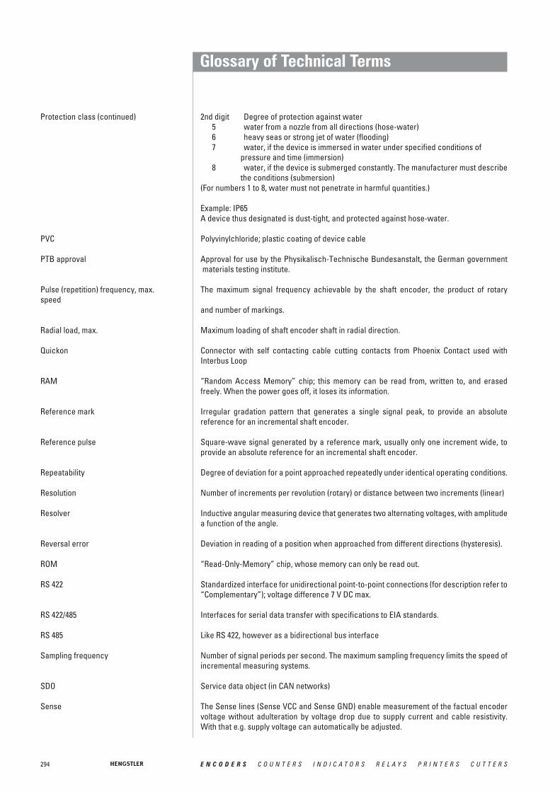
294 E N C O D E R S C O U N T E R S I N D I C A T O R S R E L A Y S P R I N T E R S C U T T E R S
Glossary of Technical Terms
Protection class (continued) 2nd digit Degree of protection against water5 water from a nozzle from all directions (hose-water)6 heavy seas or strong jet of water (flooding)7 water, if the device is immersed in water under specified conditions of
pressure and time (immersion)8 water, if the device is submerged constantly. The manufacturer must describe
the conditions (submersion)(For numbers 1 to 8, water must not penetrate in harmful quantities.)
Example: IP65A device thus designated is dust-tight, and protected against hose-water.
PVC Polyvinylchloride; plastic coating of device cable
PTB approval Approval for use by the Physikalisch-Technische Bundesanstalt, the German governmentmaterials testing institute.
Pulse (repetition) frequency, max. The maximum signal frequency achievable by the shaft encoder, the product of rotaryspeed
and number of markings.
Radial load, max. Maximum loading of shaft encoder shaft in radial direction.
Quickon Connector with self contacting cable cutting contacts from Phoenix Contact used with Interbus Loop
RAM “Random Access Memory” chip; this memory can be read from, written to, and erased freely. When the power goes off, it loses its information.
Reference mark Irregular gradation pattern that generates a single signal peak, to provide an absolute reference for an incremental shaft encoder.
Reference pulse Square-wave signal generated by a reference mark, usually only one increment wide, to provide an absolute reference for an incremental shaft encoder.
Repeatability Degree of deviation for a point approached repeatedly under identical operating conditions.
Resolution Number of increments per revolution (rotary) or distance between two increments (linear)
Resolver Inductive angular measuring device that generates two alternating voltages, with amplitudea function of the angle.
Reversal error Deviation in reading of a position when approached from different directions (hysteresis).
ROM “Read-Only-Memory” chip, whose memory can only be read out.
RS 422 Standardized interface for unidirectional point-to-point connections (for description refer to “Complementary”); voltage difference 7 V DC max.
RS 422/485 Interfaces for serial data transfer with specifications to EIA standards.
RS 485 Like RS 422, however as a bidirectional bus interface
Sampling frequency Number of signal periods per second. The maximum sampling frequency limits the speed of incremental measuring systems.
SDO Service data object (in CAN networks)
Sense The Sense lines (Sense VCC and Sense GND) enable measurement of the factual encoder voltage without adulteration by voltage drop due to supply current and cable resistivity. With that e.g. supply voltage can automatically be adjusted.

295E N C O D E R S C O U N T E R S I N D I C A T O R S R E L A Y S P R I N T E R S C U T T E R S
Glossary of Technical Terms
Scaling For programmable absolute shaft encoders the encoder actual value is multiplied by a scaling factor. Thus the resolution (increments per measuring distance or increments per revolution) is adaptable to the respective application.
SSI Synchronous-serial Interface; standardized interface for serial data transfer
TPE Thermo-plastic polyester elastomer; plastic coating of device cable
Tristate Control input; switches the outputs either to active or to high impedance.
Two's complement Number format for the representation of negative numbers; range of values at n bit: -(2n -1) … 0… (2n-1 -1)

296 E N C O D E R S C O U N T E R S I N D I C A T O R S R E L A Y S P R I N T E R S C U T T E R S
Sales and Service international
Argentina Zeising y Cia. S.A.Perú 245, C.P. (C1067AAE)Buenos AiresTel. (5411) 4345-2321Fax (5411) [email protected]://www.zeising .com.ar/
Australia Automated ControlEngineering Group Pty Ltd. Unit 1, 64 Munibung RoadCardiff NSW 2285Tel. +61-2- 4954 5004Fax +61-2- 4956 [email protected]://www.aceg.com.au/
Austria Tischer Handels GmbHIndustriestr. 23A-2353 GuntramsdorfTel. 0043-(0) 2236-89 3323-0Fax 0043-(0) [email protected]: 0043-676-7503925
Belgium Geveke Industrial BelgiumLeuvensesteenweg 250 A1800 VilvoordeTel. 0032-2257.02.40Fax [email protected]://www.geveke-industrial.be/
Brasil Veeder Root do BrasilCom. e. Ind. Ltda.Rua Ado Benatti, 92Sao Paulo SPCEP 05037-904Tel. 5511 861-2155Fax 5511 [email protected]
Chile Vignola y Cia. Ltda.P.O. Box 93-VCPIO-Subida El Peral 25ValparaisoTel. 0056-3225-6521Fax [email protected]
China Hengstler GmbH - Shanghai OfficeRoom 904, Tower 1Shanghai Kerry Everbright CityNo 218 Tian Mu Road WestShanghai 200070 ChinaTel: 86-21-33030472Fax: [email protected]
Hengstler GmbH - Beijing OfficeRoom 2202, Scitech Tower22 Jianguomen Wai StreetBeijing 100004 PR ChinaTel: 86-10-6512-0195Fax: [email protected]
Great Britain West InstrumentsThe HydeBrighton, East SussexBN2 4JU, EnglandTel. +44 (0) 1273 606271Fax +44 (0) 1273 [email protected]://www.west-inst.co.uk
Greece Control System Ltd.13 Chlois st546 27 ThessalonikiTel. (031) 527228Fax (031) [email protected]
Hong Kong Automate Control Engineering LtdUnit 1505 Entrepot Centre,117 How Ming Street, Kwun Tong,Kowloon, Hong KongTel: 852-2342-7276Fax: [email protected]
Hungary C+D Automatika KFTPostfach 1561701 BudapestTel. (0036) 1 2829 896Fax (0036) 1 2823 [email protected]://www.cdaut.hu/
India Proximon Controls Pvt. Ltd.202, Krishna Laxmi Industrial ComplexPokhran Road No. 1Vartak NagarThane - 400 606Tel. 91 -22 - 2588 92 44 / 45
91- 22 - 2585 42 87Fax. 91-22 - 2588 92 [email protected]://www.proximon.com/
India North India Territory:Kudamm CorporationD-17, IInd Floor, KalkajiOpp.Nehru Place Bus TerminalNew Delhi -110019, IndiaTel: 91-11-26423028Fax: 91-11-26479097Email: [email protected]
Indonesia Anugerah AbadiHayam Wuruk IndahLindevetesLantai Dasar Blok DKSNo. 82Jakarta - Jl. HayamWurukTel.+ Fax: [email protected]
Israel Albas Electronics Ltd.1 Hanofar Str.43662 RaananaTel.: +97 297458880Fax: +97 297458881
China Automate Control Engineering Ltd.Room G, 16/F.,No.1 Building, No.445,Tian He Bei Road, GuangzhouGuangdong Provice.Tel: (020) 38845119Fax: (020) [email protected]
Automate Control Engineering Ltd.702 room, Tower 9 , No 228Guangxi North Road,Huangpu Borough, ShanghaiTel: (021) 63526529, 63526539Fax: (021) [email protected]
Beijing Westman AutomationTechnology Lt. CoRoom 1207, Xuezhixuan BuildingNo. 16 Xueqing RoadHaidian DistrictBeijing 100083PR ChinaTel: 86-10-82755948Fax: [email protected]
Czech SETRON, s.r.o.Republic K Mejtu 11
142 00 Praha 4-PlsniceTel. 00420-2-619 10 222Fax 00420-2-619 10 225Mobil: 00420-601-211 [email protected]://www.setron.cz- not for "Printers"
Denmark Carlo Gavazzi Handel A/SOver Hadstenvej 428370 HadstenTel. 0045-89 60 61 00Fax 0045-86 98 1 [email protected]
Finland Sensorola OyVanha Porvoontie 22901380 VantaaTel. 0358-9-8386460Fax [email protected]://www.sensorola.fi/
France Hengstler Contrôle Numérique SARLZ.I. des Mardelles94-106 Rue Blaise Pascal, B.P. 7193602 Aulnay-sous-Bois, CédexTel. (01) 48795501Fax (01) 48795561http://www.hengstler.fr
Guatemala Impex Ltda.1a Avda. 10-81Zona 108é NivelCiudad de GuatemalaTel. 502 332 7432Fax 502 332 [email protected]

297E N C O D E R S C O U N T E R S I N D I C A T O R S R E L A Y S P R I N T E R S C U T T E R S
Sales and Service international
Italia ICG Holding S.r.l.Via Leonardo da Vinci, 45/4720020 Lainate (MI)Tel. 0039-02 9330011Fax 0039-02 [email protected]
Japan Danaher ICG Japan Co. Ltd.1-8-5, Asagayaminami Suginami-KuTokyo 166-0004Tel. (03) 5306-0150Fax (03) 5306-0160
Danaher ICG Japan Co. Ltd.2-12-23, Minamikaneden Suita-shiOsaka 564-0044Tel. (06) 6386-8001Fax (06) [email protected]
Korea Dae-Hyun Sangong Co., LtdRoom No.B-607, Woolimmm Lions Valley.#371-62, Gasan-Dong, Geumcheom-GuSeoul, Korea Tel. 0082-2-206-4321Fax [email protected]
Wooil EngineeringRoom # 805, 302dongBucheon Techno park,365 SamjeongdongOjeong-gu, Bucheon-si Kyunggi-do KOREATel: 82-2-652-5622Fax: [email protected]
Lebanon Incotel ElectronicsFacing Dora GateBeirutTel. 00961-1-240003Fax [email protected]
Luxemburg ➞ Belgium
Malaysia FEG Components Sdn BhdNo. 6-2, (1st Floor), Jalan USJ 9/5NSubang Business Centre,UEP Subang Jaya47620 Subang Jaya, Selangor Tel. 60-3-7245748Fax [email protected]
Mexico Comp. Ferretera Mexicana S.A. de CV.16 de Septiembre No. 58 Apartado Postal 14806000 Mexico, D.F. Tel. 0052-55-5518-4930 Tel. 0052-55-5512-2400Fax [email protected]
Singapore Danaher Industrial Controls Group Singapore246 MacPherson Road#08-01 Betime BuildingSingapore 348578Tel. 65-6-7459265, Fax 65-6-7461791Pager: [email protected]
TDS Technology (S) Pte Ltd.4 Sungei Kadut Loop(HOCEN Building, 3rd. Storey)Singapore 729493 Tel. (65) 366 1661Fax (65) 362 [email protected]://www.tdstech.com/
Slovenia TIPTEH D.O.O.Ulica Ivana Roba 211000 LjubljanaTel. (061) 200 51 50Fax (061) 200 51 [email protected].//www. tipteh.si
South Africa Countapulse Controls (Pty) Ltd.Cleveland, 2022P.O. Box 40393313 Jules StreetMalvern, 2094Tel. (011) 615 7556/7/8Fax (011) 615 [email protected]
Spain Carlo Gavazzi, S.A.Ava. Iparraguirre, 80-8248940 Leioa (Bizkaia)Tel. 0034-94-480 40 37Fax 0034-94-480 10 [email protected]://www.carlogavazzi.com/ac/es
Sweden ACUMO ABHans Stahles väg S-14741 TumbaTel. +46 8 53065840Fax.+46 8 [email protected]:// www.acumo.se
Switzerland Digana AGRotackerstrasse 218304 WallisellenTel. (01) 8300893Fax (01) [email protected]://www.digana.ch/
Netherlands Geveke IndustrialDe Meerheuvel 6a5221 EA 's-HertogenboschPostbus 22325202 CE's HertogenboschTel. +31-(0) 73-6391639Fax +31-(0) [email protected]://www.geveke-industrial.nl/
New Zealand EMC Industrial Group Ltd.P.O. Box 101444NSMC, AucklandTel. (09) 415 5110Fax (09) 415 [email protected]
Norway Hecotron Industriell Elektronikk ASPostboks 4269, TorshóvGunnar Schjelderupsv.904001 OsloTel. (22) 159 615Fax (22) 22 93 [email protected]
Norway Only for Controllers:Carlo Gavazzi ASP.O. Box 2153901 PorsgrunnTel. 0047-35 93 08 00Fax 0047-35 93 08 [email protected]://productsonline.info
Peru Ing. E. Brammertz S.C.R.L.Apdo. 0173Miraflores-Lima 18Tel. +51-1-445 81 78Fax +51-1-445 01 [email protected]
Philippines JMTI Industrial CorporationRM 203 Comfoods BuildingSen. Gil Puyat Ave.Makati Metro ManilaTel. 0063-32-8446326Fax [email protected]
Poland Eltronpl.Wolnosci 7 B50-071 WroclawTel. 0048-71-343 97 55Fax 0048-71-344 11 [email protected]
Portugal Carlo Gavazzi LdaRua dos Jeronimos 38-B1400-212 LisboaTel. +351 21 361 70 60Fax +351 21 362 13 73carlogavazzi@carlo gavazzi.pt
Cont
act

298 E N C O D E R S C O U N T E R S I N D I C A T O R S R E L A Y S P R I N T E R S C U T T E R S
Sales and Service international
USA Danaher Controls1675 Delaney RoadGurnee, IL 60031-1282Tel. (847) 662.2666Fax (847) [email protected]://www.dancon.com/
Danaher Controls2100 W. Broad StreetElisabethtown, NC 28337Tel. 910-862 2511Fax 910 862 5400http://www.dancon.com/
HECON2100 West Broad StreetP.O. Box 368Elizabethtown, NC 28337Tel. 910.879.5493Fax [email protected]://www.hecon.com- only for Printers + Cutters
Venezuela Victor Rafael Escobar + CA.Apartado de Correos, 50 113Caracas-1050-ATel. (02) 715235/729059Fax (02) 7629059
Vietnam Hoang Quoc Co. Ltd.509 Kimma Str.Badinh DistrictHanoi-S.R.VietnamTel: 0084-4-8317421Fax: [email protected]
Taiwan King-E Lu Ltd.R. o. C.10F-3, No. 20 Min Chuan West RoadP.O. Box 68-118118 TaipeiTel. (02) 25223056Fax (02) [email protected]
Distributor:Rotech Enterprise Co. Ltd.6F,No.3,Lane 26,Kuang-Fu N.RoadTaipeiTel : 886-2-25781261Fax : [email protected]
Thailand Industrial Electrical Co., Ltd.85/2, 85/3 Soi Sot Phin SanRang Nam Road, Rajthevee10400 BangkokTel. 66-2-642-6700Fax [email protected]://www.ie.co.th/
Turkey Arslan Elektronik Doz. Dipl.-Ing. Osman Arslan Lüleci Hendek Caddesi No. 4780020 Karaköy-IstanbulTel. 0212-2434627-2493134-292577Fax 0212-251 8385 [email protected]://abone.turk.net/arslane
U.A.E. Descon Trading L.L.CUnited P.O. Box 14675Arab DubaiEmirates Tel. 00971-4-2653651
299E N C O D E R S C O U N T E R S I N D I C A T O R S R E L A Y S P R I N T E R S C U T T E R S
GENERAL CONDITIONSFOR THE SUPPLY OF PRODUCTS AND SERVICES
OF THE ELECTRICAL AND ELECTRONICS INDUSTRY*for commercial transactions between businesses
– January 2002 –
© 2002 Zentralverband Elektrotechnik- und Elektronikindustrie (ZVEI) e. V., Stresemannallee 19, 60596 Frankfurt am Main. All rights reserved.
ZentralverbandElektrotechnik- undElektronikindustrie e.V.
I. GENERAL
1. The scope of deliveries and/or services (hereinafter referred to as„Supplies“) shall be determined by the written declarations of both Parties.General terms and conditions of the Purchaser shall apply only if and whenexpressly accepted by the supplier or the provider of services (hereinafterreferred to as „Supplier“) in writing.
2. The Supplier herewith reserves any industrial property rights and/or copy-rights pertaining to its cost estimates, drawings and other documents (here-inafter referred to as „Documents“). The Documents shall not be madeaccessible to third parties without the Supplier’s prior consent and shall,upon request, be returned without undue delay to the Supplier if the con-tract is not awarded to the Supplier. Sentences 1 and 2 shall apply mutatismutandis to documents of the Purchaser; these may, however, be madeaccessible to third parties to whom the Supplier may rightfully transferSupplies.
3. The Purchaser shall have the non-exclusive right to use standard software,provided that it remains unchanged, is used within the agreed performanceparameters, and on the agreed equipment. The Purchaser may make oneback-up copy without express agreement.
4. Partial Supplies shall be allowed, unless they are unreasonable to accept forthe Purchaser.
II. PRICES AND TERMS OF PAYMENT
1. Prices shall be ex works and exclude packaging; value added tax shall beadded at the then applicable rate.
2. If the Supplier is also responsible for assembly or erection and unless oth-erwise agreed, the Purchaser shall pay the agreed remuneration and anyincidental costs required, e. g. travel costs, costs for the transport of toolsand equipment, and personal luggage as well as allowances.
3. Payments shall be made free Supplier’s paying office.
4. The Purchaser may set off only those claims that are undisputed or againstwhich no legal recourse is possible.
III. RETENTION OF TITLE
1. Items pertaining to the Supplies („Retained Goods“) shall remain the prop-erty of the Supplier until each and every claim the Supplier has against thePurchaser on account of the business connection has been fulfilled. If thecombined value of the security interests of the Supplier exceeds the valueof all secured claims by more than 20 %, the Supplier shall release a corre-sponding part of the security interest if so requested by the Purchaser.
2. For the duration of the retention of title, the Purchaser may not pledge theRetained Goods or use them as security, and resale shall be possible onlyfor resellers in the ordinary course of their business and only on conditionthat the reseller receives payment from its customer or makes the transferof property to the customer dependent upon the customer fulfilling its obli-gation to effect payment.
3. The Purchaser shall inform the Supplier forthwith of any seizure or other actof intervention by third parties.
4. Where the Purchaser fails to fulfil its duties, including failure to make pay-ments due, the Supplier shall be entitled to cancel the contract and takeback the Retained Goods in the case of continued failure following expiry ofa reasonable time set by the Supplier; the statutory provisions that a timelimit is not needed remain unaffected. The Purchaser shall be obliged to sur-render the Retained Goods.
IV. TIME FOR SUPPLIES; DELAY
1. Times set for Supplies can only be observed if all Documents to be suppliedby the Purchaser, necessary permits and releases, especially concerningplans, are received in time and if agreed terms of payment and other obli-gations of the Purchaser are fulfilled. Unless these conditions are fulfilled intime, times set shall be extended appropriately; this shall not apply wherethe Supplier is responsible for the delay.
2. If non-observance of the times set is due to force majeure such as mobi-lization, war, rebellion or similar events, e. g. strike or lockout, such timeshall be extended accordingly.
3. If the Supplier is responsible for the delay (hereinafter referred to as „Delay“)and the Purchaser demonstrably suffered a loss therefrom, the Purchaser
may claim a compensation as liquidated damages of 0.5 % for every com-pleted week of Delay, but in no case more than a total of 5 % of the price ofthat part of the Supplies which because of the Delay could not be put to theintended use.
4. Purchaser’s claims for damages due to delayed Supplies as well as claimsfor damages in lieu of performance exceeding the limits specified in No. 3above shall be excluded in all cases of delayed Supplies even upon expiryof a time set to the Supplier to effect the Supplies. This shall not apply incases of mandatory liability based on intent, gross negligence, or due toinjury of life, body or health. Cancellation of the contract by the Purchaserbased on statute shall be limited to cases where the Supplier is responsiblefor the delay. The above provisions do not imply a change in the burden ofproof to the detriment of the Purchaser.
5. At the Supplier’s request the Purchaser shall declare within a reasonableperiod of time whether the Purchaser cancels the contract due to thedelayed Supplies or insists on the Supplies to be carried out.
6. If dispatch or shipment is delayed at the Purchaser’s request by more thanone month after notice of the readiness for dispatch was given, thePurchaser may be charged, for every month commenced, storage costs of0.5 % of the price of the items of the Supplies, but in no case more than atotal of 5 %. The parties to the contract may prove that higher or, as the casemay be, lower storage costs have been incurred.
V. TRANSFER OF RISK
1. Even where delivery has been agreed freight free, the risk shall pass to thePurchaser as follows:
a) if the Supplies do not include assembly or erection, at the time when theSupplies are shipped or picked up by the carrier. Upon request of thePurchaser, the Supplier shall insure the Supplies against the usual risksof transport at the expense of the Purchaser;
b) if the Supplies include assembly or erection, at the day of taking over inthe own works or, if so agreed, after a fault-free trial run.
2. The risk shall pass to the Purchaser if dispatch, shipping, the start or per-formance of assembly or erection, the taking over in the own works or thetrial run is delayed for reasons for which the Purchaser is responsible or ifthe Purchaser has otherwise failed to accept the Supplies.
VI. ASSEMBLY AND ERECTION
Unless otherwise agreed in writing, assembly/erection shall be subject to the following provisions:
1. The Purchaser shall provide at its own expense and in good time:
a) all earth and construction work and other ancillary work outside thescope of the Supplier, including the necessary skilled and unskilledlabour, construction materials and tools,
b) the equipment and materials necessary for assembly and commissioningsuch as scaffolds, lifting equipment and other devices as well as fuelsand lubricants,
c) energy and water at the point of use including connections, heating andlighting,
d) suitable dry and lockable rooms of sufficient size adjacent to the site forthe storage of machine parts, apparatus, materials, tools, etc. and ade-quate working and recreation rooms for the erection personnel, includingsanitary facilities as are appropriate in the specific circumstances.Furthermore, the Purchaser shall take all measures it would take for theprotection of its own possessions to protect the possessions of theSupplier and of the erection personnel at the site,
e) protective clothing and protective devices needed due to particular con-ditions prevailing on the specific site.
2. Before the erection work starts, the Purchaser shall make available of itsown accord any information required concerning the location of concealedelectric power, gas and water lines or of similar installations as well as thenecessary structural data.
3. Prior to assembly or erection, the materials and equipment necessary for thework to start must be available on the site of assembly/erection and anypreparatory work must have advanced to such a degree that assembly/erec-tion can be started as agreed and carried out without interruption. Accessroads and the assembly/erection site itself must be level and clear.
4. If assembly, erection or commissioning is delayed due to circumstances forwhich the Supplier is not responsible, the Purchaser shall bear the reason-* Translation of the original German text
Othe
rs

300 E N C O D E R S C O U N T E R S I N D I C A T O R S R E L A Y S P R I N T E R S C U T T E R S
© 2002 Zentralverband Elektrotechnik- und Elektronikindustrie (ZVEI) e. V., Stresemannallee 19, 60596 Frankfurt am Main. All rights reserved.
able costs incurred for idle times and any additional travelling of the Supplieror the erection personnel.
5. The Purchaser shall attest to the hours worked by the erection personneltowards the Supplier at weekly intervals and the Purchaser shall immediate-ly confirm in writing if assembly, erection or commissioning has been com-pleted.
6. If, after completion, the Supplier demands acceptance of the Supplies, thePurchaser shall comply therewith within a period of two weeks. In defaultthereof, acceptance is deemed to have taken place. Acceptance is alsodeemed to have been effected if the Supplies are put to use, after comple-tion of an agreed test phase, if any.
VII. RECEIVING OF SUPPLIES
The Purchaser shall not refuse to receive Supplies due to minor defects.
VIII. DEFECTS AS TO QUALITY
The Supplier shall be liable for defects as to quality („Sachmängel“, hereinafterreferred to as „Defects“,) as follows:
1. All parts or services where a Defect becomes apparent within the limitationperiod shall, at the discretion of the Supplier, be repaired, replaced or pro-vided again free of charge irrespective of the hours of operation elapsed,provided that the reason for the Defect had already existed at the time whenthe risk passed.
2. Claims based on Defects are subject to a limitation period of 12 months.This provision shall not apply where longer periods are prescribed by lawaccording to Sec. 438 para. 1 No. 2 (buildings and things used for a build-ing), Sec. 479 para. 1 (right of recourse), and Sec. 634a para. 1 No. 2(defects of a building) German Civil Code („BGB“), as well as in cases ofinjury of life, body or health, or where the Supplier intentionally or grosslynegligently fails to fulfil its obligation or fraudulently conceals a Defect. Thelegal provisions regarding suspension of expiration („Ablaufhemmung“),suspension („Hemmung“) and recommencement of limitation periodsremain unaffected.
3. The Purchaser shall notify Defects to the Supplier in writing and withoutundue delay.
4. In the case of notification of a Defect, the Purchaser may withhold paymentsto a reasonable extent taking into account the Defect occurred. ThePurchaser, however, may withhold payments only if the subject-matter of thenotification of the Defect occurred is justified beyond doubt. Unjustified noti-fications of Defect shall entitle the Supplier to have its expenses reimbursedby the Purchaser.
5. The Supplier shall first be given the opportunity to supplement its perfor-mance („Nacherfüllung“) within a reasonable period of time.
6. If supplementary performance is unsuccessful, the Purchaser shall be enti-tled to cancel the contract or reduce the remuneration, irrespective of anyclaims for damages it may have according to Art. XI.
7. There shall be no claims based on Defect in cases of insignificant deviationsfrom the agreed quality, of only minor impairment of usefulness, of naturalwear and tear or damage arising after the transfer of risk from faulty or neg-ligent handling, excessive strain, unsuitable equipment, defective workman-ship, inappropriate foundation soil or from particular external influences notassumed under the contract, or from non-reproducible software errors.Claims based on defects attributable to improper modifications or repairwork carried out by the Purchaser or third parties and the consequencesthereof shall be likewise excluded.
8. The Purchaser shall have no claim with respect to expenses incurred in thecourse of supplementary performance, including costs of travel and trans-port, labour, and material, to the extent that expenses are increasedbecause the subject-matter of the Supplies was subsequently brought toanother location than the Purchaser’s branch office, unless doing so com-plies with the intended use of the Supplies.
9. The Purchaser’s right of recourse against the Supplier pursuant to Sec. 478BGB is limited to cases where the Purchaser has not concluded an agree-ment with its customers exceeding the scope of the statutory provisionsgoverning claims based on Defects. Moreover, No. 8 above shall applymutatis mutandis to the scope of the right of recourse the Purchaser hasagainst the Supplier pursuant to Sec. 478 para. 2 BGB.
10. Furthermore, the provisions of Art. XI (Other Claims for Damages) shall applyin respect of claims of damages. Any other claims of the Purchaser againstthe Supplier or its agents or any such claims exceeding the claims providedfor in this Art. VIII, based on a Defect, shall be excluded.
IX. INDUSTRIAL PROPERTY RIGHTS AND COPYRIGHT;DEFECTS IN TITLE
1. Unless otherwise agreed, the Supplier shall provide the Supplies free fromthird parties’ industrial property rights and copyrights (hereinafter referred toas „IPR“) with respect to the country of the place of destination. If a thirdparty asserts a justified claim against the Purchaser based on an infringe-ment of an IPR with respect to the Supplies made by the Supplier and thenused in conformity with the contract, the Supplier shall be liable to thePurchaser within the time period stipulated in Art. VIII No. 2 as follows:
a) The Supplier shall choose whether to acquire, at its own expense, theright to use the IPR with respect to the Supplies concerned or whether to
modify the Supplies such that they no longer infringe the IPR or replacethem. If this would be unreasonable to demand from the Supplier, thePurchaser may cancel the contract or reduce the remuneration pursuantto the appli-cable statutory provisions.
b) The Supplier’s liability to pay damages shall be governed by Art. XI.
c) The above obligations of the Supplier shall only apply if the Purchaser (i) immediately notifies the Supplier of any such claim asserted by the thirdparty in writing, (ii) does not concede the existence of an infringement and(iii) leaves any protective measures and settlement negotiations to the dis-cretion of the Supplier. If the Purchaser stops using the Supplies in orderto reduce the damage or for other good reason, it shall be obliged to pointout to the third party that no acknowledgement of the alleged infringe-ment may be inferred from the fact that the use has been discontinued.
2. Claims of the Purchaser shall be excluded if it is itself responsible for theinfringement of an IPR.
3. Claims of the Purchaser shall also be excluded if the infringement of the IPRis caused by specifications made by the Purchaser, to a type of use not fore-seeable by the Supplier or to the Supplies being modified by the Purchaseror being used together with products not provided by the Supplier.
4. In addition, with respect to claims by the Purchaser pursuant to No. 1 a)above, Art. VIII Nos. 4, 5, and 9 shall apply mutatis mutandis in the event ofan infringement of an IPR.
5. Where other defects in title occur, Art. VIII shall apply mutatis mutandis.
6. Any other claims of the Purchaser against the Supplier or its agents or anysuch claims exceeding the claims provided for in this Art. IX, based on adefect in title, shall be excluded.
X. IMPOSSIBILITY OF PERFORMANCE; ADAPTATION OF CONTRACT
1. To the extent that Supplies are impossible to be carried out, the Purchasershall be entitled to claim damages, unless the Supplier is not responsible forthe impossibility. The Purchaser’s claim for damages shall, however, be lim-ited to an amount of 10 % of the value of the part of the Supplies which,owing to the impossibility, cannot be put to the intended use. This limitationshall not apply in the case of mandatory liability based on intent, gross neg-ligence or injury of life, body or health; this does not imply a change in theburden of proof to the detriment of the Purchaser. The right of the Purchaserto cancel the contract shall remain unaffected.
2. Where unforeseeable events within the meaning of Art. IV No. 2 substantial-ly change the economic importance or the contents of the Supplies or con-siderably affect the Supplier’s business, the contract shall be adapted ta-king into account the principles of reasonableness and good faith. Wheredoing so is economically unreasonable, the Supplier shall have the right tocancel the contract. If the Supplier intends to exercise its right to cancel thecontract, it shall notify the Purchaser thereof without undue delay after hav-ing realised the repercussions of the event; this shall also apply even wherean extension of the delivery period had previously been agreed with thePurchaser.
XI. OTHER CLAIMS FOR DAMAGES
1. Any claims for damages and reimbursement of expenses the Purchaser mayhave (hereinafter referred to as „Claims for Damages“), based on whateverlegal reason, including infringement of duties arising in connection with thecontract or tort, shall be excluded.
2. The above shall not apply in the case of mandatory liability, e. g. under theGerman Product Liability Act („Produkthaftungsgesetz“), in the case ofintent, gross negligence, injury of life, body or health, or breach of a condi-tion which goes to the root of the contract („wesentliche Vertragspflichten“).However, Claims for Damages arising from a breach of a condition whichgoes to the root of the contract shall be limited to the foreseeable damagewhich is intrinsic to the contract, unless caused by intent or gross negli-gence or based on liability for injury of life, body or health. The above provi-sion does not imply a change in the burden of proof to the detriment of thePurchaser.
3. To the extent that the Purchaser has a valid Claim for Damages accordingto this Art. XI, it shall be time-barred upon expiration of the limitation periodapplicable to Defects pursuant to Art. VIII No. 2. In the case of claims fordamages under the German Product Liability Act, the statutory provisionsgoverning limitation periods shall apply.
XII. VENUE AND APPLICABLE LAW
1. If the Purchaser is a businessperson, sole venue for all disputes arisingdirectly or indirectly out of the contract shall be the Supplier’s place of busi-ness. However, the Supplier may also bring an action at the Purchaser’splace of business.
2. Legal relations existing in connection with this contract shall be governed byGerman substantive law, to the exclusion of the United Nations Conventionon Contracts for the International Sale of Goods (CISG).
XIII. SEVERABILITY CLAUSE
The legal invalidity of one or more provisions of this contract shall in no wayaffect the validity of the remaining provisions. This shall not apply if it would beunreasonable for one of the parties to continue the contract.

E N C O D E R S C O U N T E R S I N D I C A T O R S R E L A Y S P R I N T E R S C U T T E R S
Notes
E N C O D E R S C O U N T E R S I N D I C A T O R S R E L A Y S P R I N T E R S C U T T E R S

Enco
ders
Encoders■ Incremental
■ Absolute
■ MotorFeedback Systems
Innovative products from yourcompetent partner. Worldwide
DOC 1209.18 EEncoders programme · 01/2006 / 1500 · HohlDruckprinted in Germany on environmentally friendly paperfrom chlorine- and acid-free production
■ AGENTSArgentina, Australia, Austria, Belgium, Brazil, Chile, China, Czech Republic, Denmark, Finland, France, Germany, Guatemala, Great Britain, Greece, Hong Kong,Hungary, India, Indonesia, Israel, Italia, Japan, Korea, Lebanon, Luxemburg, Malaysia, Mexico, Netherlands, New Zealand, Norway, Peru, Philippines, Poland,Portugal, Singapore, Slovenia, South Africa, Spain, Sweden, Switzerland, Taiwan, Thailand, Turkey, United Arab Emirates, USA, Venezuela, Vietnam
HENGSTLER INTERNATIONAL
■ GERMANYHengstler GmbHUhlandstr. 4978554 Aldingen Tel. +49-74 24-8 90Fax +49-74 24-8 94 70/ 89 500http://[email protected]
■ FRANCEHengstler Contrôle Numérique S.A.R.L.Z.I. des Mardelles94-106, Rue Blaise Pascal, B.P. 7193602 Aulnay-sous-Bois, CédexTel. (01) 48795500Fax (01) 48795561http://www.hengstler.fr
■ GREAT BRITAINWest InstrumentsThe HydeBrighton, East SussexBN2 4JU, EnglandTel. +44 (0) 1273 606271Fax +44 (0) 1273 [email protected]://www.westinstruments.com
■ ITALYICG Holding S.r.l.Via Leonardo da Vinci, 45/4720020 Lainate (MI)Tel. 0039-02 9330011Fax 0039-02 [email protected]
■ SLOVAKIAHengstler sroPradiaren 40060 01 Kezmarok Tel :+421 52 46803 19,Fax:+421 52 46803 [email protected]
■ BRASILVeeder Root do BrasilCom. e. Ind. Ltda.Rua Ado Benatti, 92Sao Paulo SPCEP 05037-904Tel 0055 11 361 121 55Fax 0055 11 36 11 [email protected]
■ CHINADanaher ICG ChinaShanghai OfficeRoom.904,Tower 1,Kerry Everbright CityNo.218,Tian Mu Road(W) Shanghai 200070, ChinaTel:+86 21 63539541, 33030472 Fax:+86 21 [email protected]
■ CHINADanaher ICG - ChinaBeijing OfficeRoom 2202, Scitech Tower22 Jianguomen Wai StreetBeijing 100004 PR ChinaTel: 86-10-6512-0195Fax: [email protected]
■ CHINADanaher ICG - ChinaGuangzhou Office Room B2, 15th Floor,Gao Sheng BuildingNo.109 Ti Yu Xi RoadGuangzhou 510620, ChinaTel: +86 20-22646072Fax: +86 [email protected]
Hengstler GmbHUhlandstr. 4978554 Aldingen Tel. +49-74 24-8 90Fax +49-74 24-8 94 70/ 89 500http://[email protected]
DQS certified according DIN EN ISO 9001 Reg. No. 1540-01
■ JAPANDanaher ICG Japan Co. Ltd.2-12-23, MinamikanedenSuita-shiOsaka 564-0044Tel. (06) 63868001Fax (06) [email protected]://www.hengstler.co.jp/
■ SINGAPOREDanaher Industrial Control Group - Singapore246 MacPherson Road#08-01 Betime BuildingSingapore 348578Tel. 65-6-7459265, Fax 65-6-7461791Pager: [email protected]
■ USADanaher Controls1675 Delaney RoadGurnee, IL 60031-1282Tel. (847) 662.2666Fax (847) [email protected]://www.dancon.com
■ USAHECON2100 West Broad StreetP.O. Box 368Elizabethtown, NC 28337Tel. 910.879.5493Fax [email protected]://www.hecon.com- nur für Drucker + Abschneider- only for Printers + Cutters


![NWB application data in Japan(LHD) · [Notes] 1. Only major models which is sold in Japan domestic are mentioned. 2. No applicable items for the following, 【a】 Possibility to](https://img.pdfslide.net/doc/110x75/607f4d5462d902702b0fefa2/nwb-application-data-in-japanlhd-notes-1-only-major-models-which-is-sold-in.jpg)


![NWB application data in Japan(RHD) · 2017. 1. 21. · [Notes] 1. Only major models which is sold in Japan domestic are mentioned. 2. No applicable items for the following, 【a】](https://img.pdfslide.net/doc/110x75/607f4dea1cb4de54994fe196/nwb-application-data-in-japanrhd-2017-1-21-notes-1-only-major-models-which.jpg)