Embed Size (px)
Citation preview
SECTION 07 76 00ADJUSTABLE PEDESTALS FOR TERRACES
Display hidden notes to specifier. (Don't know how? Click Here)
Copyright 2016 - 2017 ARCAT, Inc. - All rights reserved
1 GENERAL
1.1 SECTION INCLUDES
1.1.1 Adjustable pedestals for terraces.
1.2 RELATED SECTIONS
1.2.1 Section 32 14 23 - Asphalt Unit Paving.
1.2.2 Section 04 22 23.29 - Split-Face Concrete Unit Masonry.
1.2.3 Section 04 40 00 - Stone Assemblies.
1.2.4 Section 06 15 00 - Wood Decking.
1.2.5 Section 06 50 00 - Structural Plastics.
1.2.6 Section 06 73 00 - Composite Decking.
1.2.7 Section 07 50 00 - Membrane Roofing.
1.2.8 Section 07 72 13 - Manufactured Curbs.
1.2.9 Section 07 76 13 - Roof Ballast Pavers.
1.2.10 Section 09 01 60.91 - Flooring Restoration.
1.3 REFERENCES
1.3.1 Belgium (CRIF) Centre De Recherches Scientifiques ET Techniques Del Industrie Des Fabrications: Test Report No. GT 7660/01.
1.4 SUBMITTALS
07 76 00-1
1.4.1 Submit under provisions of Section 01 30 00 - Administrative Requirements.
1.4.2 Product Data: Manufacturer's data sheets for each assembly specified, including but not limited to:1.4.2.1 Performance characteristics.1.4.2.2 Preparation instructions and recommendations.1.4.2.3 Storage and handling requirements and recommendations.1.4.2.4 Installation methods.
1.4.3 Method Statement: Prior to the installation of adjustable pedestal decking systems, Contractor shall submit an installation ' method statement' setting out the installation procedure for approval.
1.4.4 Engineering Calculations:1.4.4.1 Dead Load and Live Load Calculations: Indicating structure is designed to carry
dead load and live load weights specific to application.1.4.4.2 Density of Insulation: Sufficient to resist crushing and damaging waterproofing
membrane.
1.4.5 Shop Drawings: Provide plans, elevations, sections, fabrication, installation, anchorage, interface of the work of this section with the work of adjacent trades and indicating dimensions, tolerances and finishes.
1.4.6 Verification Samples: For each finish product specified, two samples representing actual product assembly types specified.
1.5 QUALITY ASSURANCE
1.5.1 Single Source Requirements: To the greatest extent possible, provide pedestals and ancillary products specified in this section from a single manufacturer.
1.5.2 Manufacturer's Qualifications: Successfully engaged in the manufacture of adjustable pedestals for terraces for at least 10 years.
1.5.3 Installer Qualifications: Successfully engaged in installation of adjustable decking systems for at least 2 years; capable of estimating, building from working CAD details or plans, determining elevations and properly handling materials in pedestal decking assembly.1.5.3.1 Method Statement Submission: Prior to the installation of the adjustable pedestal
decking systems, the installer shall submit an installation ' method statement' setting out the installation procedure for approval.
1.5.4 Mock-Up: Provide a mock-up for evaluation of surface preparation techniques and application workmanship.1.5.4.1 Finish areas designated by Architect.1.5.4.2 Do not proceed with remaining work until workmanship is approved by Architect.1.5.4.3 Rebuild mock-up area as required to produce acceptable work.
1.6 PRE-INSTALLATION MEETINGS
1.6.1 Conference: Convene a pre-installation conference to establish procedures to maintain optimum working conditions and to coordinate this work with related and adjacent work.
1.7 DELIVERY, STORAGE AND HANDLING
1.7.1 Deliver and store products in manufacturer's unopened packaging bearing the brand name and manufacturer's identification until ready for installation. Pedestals are delivered boxed in cardboard cartons. These cartons should be stored in dry conditions and should not come into contact with rain or damp conditions. Protect from damage.
07 76 00-2
1.7.2 Handling: Handle materials to avoid damage.
1.8 PROJECT CONDITIONS
1.8.1 Maintain environmental conditions (temperature, humidity, and ventilation) within limits recommended by manufacturer for optimum results. Do not install products under environmental conditions outside manufacturer's absolute limits.
1.9 SEQUENCING
1.9.1 Ensure that products of this section are supplied to affected trades in time to prevent interruption of construction progress.
1.10 WARRANTY
1.10.1 Manufacturer's Warranty: Standard limited warranty against defects in materials and manufacturing.1.10.1.1 Warranty Period for Deck Pedestals: Three years.
2 PRODUCTS
2.1 MANUFACTURERS
2.1.1 Acceptable Manufacturer: BUZON USA East, which is located at: 16 W. 56th St.; New York, NY 10019; Tel: 646-929-4318; Fax: 212-243-2868; Email:request info ([email protected]); Web:www.buzonusa.us
2.1.2 Substitutions: Not permitted.
2.1.3 Requests for substitutions will be considered in accordance with provisions of Section 01 60 00 - Product Requirements.
2.2 ADJUSTABLE DECK PEDESTALS
2.2.1 Basis of Design: Buzon DPH Series Screwjack Pedestals, as manufactured by Buzon.2.2.1.1 Pedestal Component Materials: Talc-loaded polypropylene copolymer with
minimum 78 percent recycled CCP material, 20 percent Talc, 2 percent UV, Master Batch black, 100 percent recyclable. Temperature Range: Suitable for use from minus 22 to 250 degrees F (minus 30 to 120 degrees C).
2.2.1.2 Pedestal Component Materials: As scheduled and indicated on Drawings.2.2.1.3 Pedestal Component Materials: ______.2.2.1.4 Ancillary Application Materials:
2.2.1.4.1 Accommodates metal grid systems, fiberglass grid systems, timber-style decking, square-shaped or rectangular-shaped stone, concrete, natural stone, terrazzo, ceramic, composite pavers as approved by manufacturer.
2.2.1.4.2 Do not use Buzon Deck Supports over insulation less than 20 psi (134 kPa) or with low density polystyrene insulation.
2.2.1.5 Compliance:2.2.1.5.1 Testing Agency: Belgium (CRIF) Centre De Recherches Scientifiques ET
Techniques Del Industrie Des Fabrications.2.2.1.5.2 Test Method: Universal testing machine, Instron type.2.2.1.5.3 Test Report: No. GT 7660/01.2.2.1.5.4 Safety Factor for Pedestrian Terraces: Divide "Load Data" by 2 with an
additional safety factor of 15 percent.2.2.1.5.5 Safety Factor for Raised False Floors: Divide "Load Data" by 4 with an
additional safety factor of 15 percent.2.2.1.6 Configuration: As scheduled and indicated on Drawings.2.2.1.7 Configuration: DPH-0.
07 76 00-3
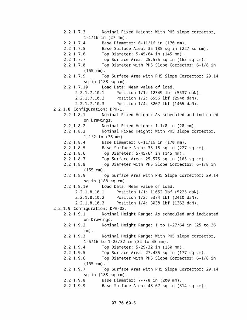
2.2.1.7.1 Nominal Fixed Height: As scheduled and indicated on Drawings.2.2.1.7.2 Nominal Fixed Height: 11/16 in (17 mm).2.2.1.7.3 Nominal Fixed Height: With PH5 slope corrector, 1-1/16 in (27 mm).2.2.1.7.4 Base Diameter: 6-11/16 in (170 mm).2.2.1.7.5 Base Surface Area: 35.185 sq in (227 sq cm).2.2.1.7.6 Top Diameter: 5-45/64 in (145 mm).2.2.1.7.7 Top Surface Area: 25.575 sq in (165 sq cm).2.2.1.7.8 Top Diameter with PH5 Slope Corrector: 6-1/8 in (155 mm).2.2.1.7.9 Top Surface Area with PH5 Slope Corrector: 29.14 sq in (188 sq cm).2.2.1.7.10 Load Data: Mean value of load.
2.2.1.7.10.1 Position 1/1: 12349 lbf (5537 daN).2.2.1.7.10.2 Position 1/2: 6556 lbf (2940 daN).2.2.1.7.10.3 Position 1/4: 3267 lbf (1465 daN).
2.2.1.8 Configuration: DPH-1.2.2.1.8.1 Nominal Fixed Height: As scheduled and indicated on Drawings.2.2.1.8.2 Nominal Fixed Height: 1-1/8 in (28 mm).2.2.1.8.3 Nominal Fixed Height: With PH5 slope corrector, 1-1/2 in (38 mm).2.2.1.8.4 Base Diameter: 6-11/16 in (170 mm).2.2.1.8.5 Base Surface Area: 35.18 sq in (227 sq cm).2.2.1.8.6 Top Diameter: 5-45/64 in (145 mm).2.2.1.8.7 Top Surface Area: 25.575 sq in (165 sq cm).2.2.1.8.8 Top Diameter with PH5 Slope Corrector: 6-1/8 in (155 mm).2.2.1.8.9 Top Surface Area with PH5 Slope Corrector: 29.14 sq in (188 sq cm).2.2.1.8.10 Load Data: Mean value of load.
2.2.1.8.10.1 Position 1/1: 11652 lbf (5225 daN).2.2.1.8.10.2 Position 1/2: 5374 lbf (2410 daN).2.2.1.8.10.3 Position 1/4: 3038 lbf (1362 daN).
2.2.1.9 Configuration: DPH-02.2.2.1.9.1 Nominal Height Range: As scheduled and indicated on Drawings.2.2.1.9.2 Nominal Height Range: 1 to 1-27/64 in (25 to 36 mm).2.2.1.9.3 Nominal Height Range: With PH5 slope corrector, 1-5/16 to 1-25/32 in (34
to 45 mm).2.2.1.9.4 Top Diameter: 5-29/32 in (150 mm).2.2.1.9.5 Top Surface Area: 27.435 sq in (177 sq cm).2.2.1.9.6 Top Diameter with PH5 Slope Corrector: 6-1/8 in (155 mm).2.2.1.9.7 Top Surface Area with PH5 Slope Corrector: 29.14 sq in (188 sq cm).2.2.1.9.8 Base Diameter: 7-7/8 in (200 mm).2.2.1.9.9 Base Surface Area: 48.67 sq in (314 sq cm).2.2.1.9.10 Load Data: Mean value of load.
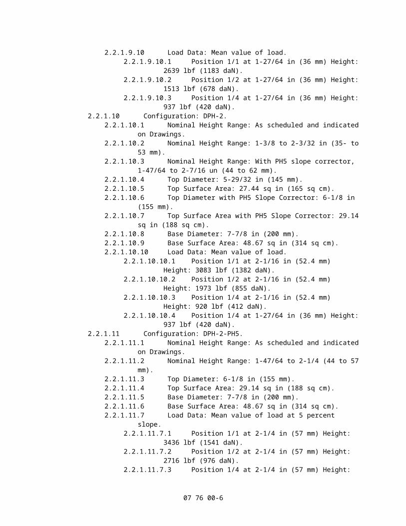
2.2.1.9.10.1 Position 1/1 at 1-27/64 in (36 mm) Height: 2639 lbf (1183 daN).2.2.1.9.10.2 Position 1/2 at 1-27/64 in (36 mm) Height: 1513 lbf (678 daN).2.2.1.9.10.3 Position 1/4 at 1-27/64 in (36 mm) Height: 937 lbf (420 daN).
2.2.1.10 Configuration: DPH-2.2.2.1.10.1 Nominal Height Range: As scheduled and indicated on Drawings.2.2.1.10.2 Nominal Height Range: 1-3/8 to 2-3/32 in (35- to 53 mm).2.2.1.10.3 Nominal Height Range: With PH5 slope corrector, 1-47/64 to 2-7/16 un (44
to 62 mm).2.2.1.10.4 Top Diameter: 5-29/32 in (145 mm).2.2.1.10.5 Top Surface Area: 27.44 sq in (165 sq cm).2.2.1.10.6 Top Diameter with PH5 Slope Corrector: 6-1/8 in (155 mm).2.2.1.10.7 Top Surface Area with PH5 Slope Corrector: 29.14 sq in (188 sq cm).2.2.1.10.8 Base Diameter: 7-7/8 in (200 mm).2.2.1.10.9 Base Surface Area: 48.67 sq in (314 sq cm).2.2.1.10.10 Load Data: Mean value of load.
2.2.1.10.10.1 Position 1/1 at 2-1/16 in (52.4 mm) Height: 3083 lbf (1382 daN).2.2.1.10.10.2 Position 1/2 at 2-1/16 in (52.4 mm) Height: 1973 lbf (855 daN).
07 76 00-4
2.2.1.10.10.3 Position 1/4 at 2-1/16 in (52.4 mm) Height: 920 lbf (412 daN).2.2.1.10.10.4 Position 1/4 at 1-27/64 in (36 mm) Height: 937 lbf (420 daN).
2.2.1.11 Configuration: DPH-2-PH5.2.2.1.11.1 Nominal Height Range: As scheduled and indicated on Drawings.2.2.1.11.2 Nominal Height Range: 1-47/64 to 2-1/4 (44 to 57 mm).2.2.1.11.3 Top Diameter: 6-1/8 in (155 mm).2.2.1.11.4 Top Surface Area: 29.14 sq in (188 sq cm).2.2.1.11.5 Base Diameter: 7-7/8 in (200 mm).2.2.1.11.6 Base Surface Area: 48.67 sq in (314 sq cm).2.2.1.11.7 Load Data: Mean value of load at 5 percent slope.
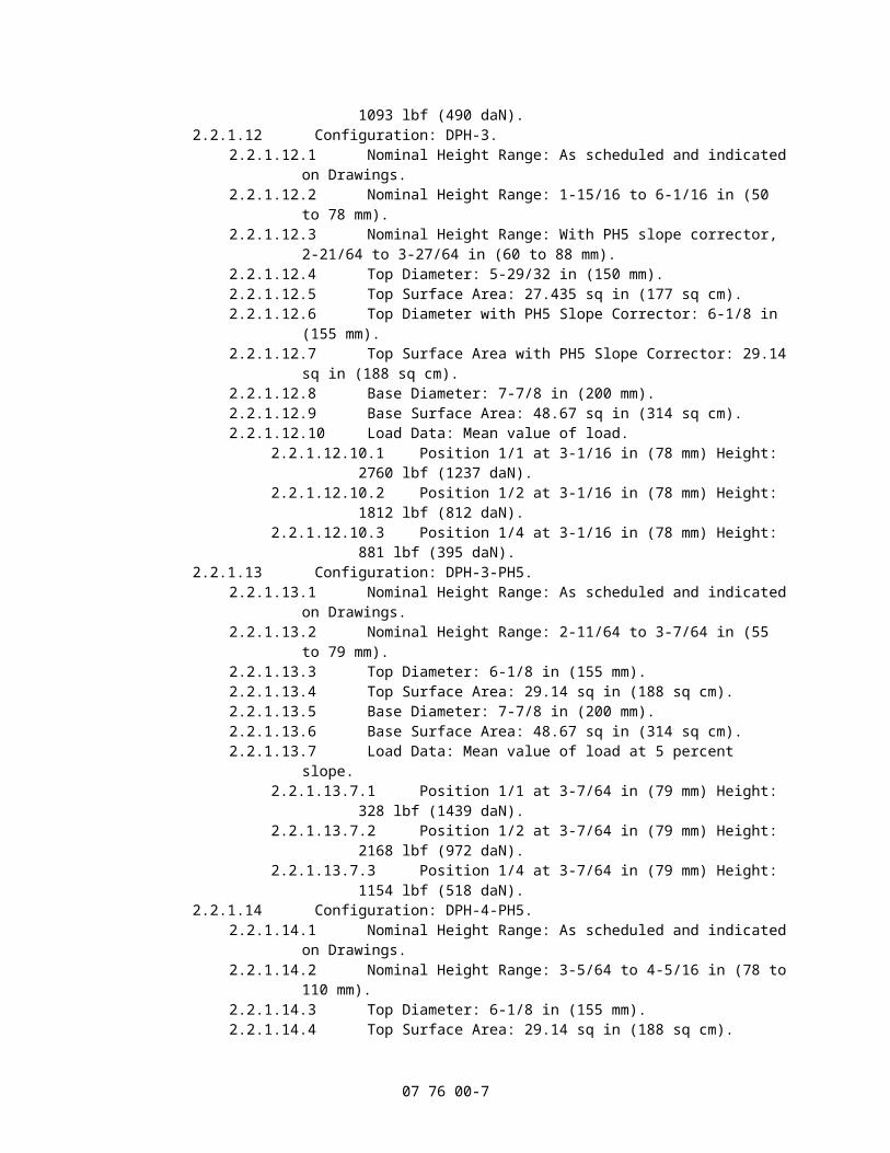
2.2.1.11.7.1 Position 1/1 at 2-1/4 in (57 mm) Height: 3436 lbf (1541 daN).2.2.1.11.7.2 Position 1/2 at 2-1/4 in (57 mm) Height: 2716 lbf (976 daN).2.2.1.11.7.3 Position 1/4 at 2-1/4 in (57 mm) Height: 1093 lbf (490 daN).
2.2.1.12 Configuration: DPH-3.2.2.1.12.1 Nominal Height Range: As scheduled and indicated on Drawings.2.2.1.12.2 Nominal Height Range: 1-15/16 to 6-1/16 in (50 to 78 mm).2.2.1.12.3 Nominal Height Range: With PH5 slope corrector, 2-21/64 to 3-27/64 in (60
to 88 mm).2.2.1.12.4 Top Diameter: 5-29/32 in (150 mm).2.2.1.12.5 Top Surface Area: 27.435 sq in (177 sq cm).2.2.1.12.6 Top Diameter with PH5 Slope Corrector: 6-1/8 in (155 mm).2.2.1.12.7 Top Surface Area with PH5 Slope Corrector: 29.14 sq in (188 sq cm).2.2.1.12.8 Base Diameter: 7-7/8 in (200 mm).2.2.1.12.9 Base Surface Area: 48.67 sq in (314 sq cm).2.2.1.12.10 Load Data: Mean value of load.
2.2.1.12.10.1 Position 1/1 at 3-1/16 in (78 mm) Height: 2760 lbf (1237 daN).2.2.1.12.10.2 Position 1/2 at 3-1/16 in (78 mm) Height: 1812 lbf (812 daN).2.2.1.12.10.3 Position 1/4 at 3-1/16 in (78 mm) Height: 881 lbf (395 daN).
2.2.1.13 Configuration: DPH-3-PH5.2.2.1.13.1 Nominal Height Range: As scheduled and indicated on Drawings.2.2.1.13.2 Nominal Height Range: 2-11/64 to 3-7/64 in (55 to 79 mm).2.2.1.13.3 Top Diameter: 6-1/8 in (155 mm).2.2.1.13.4 Top Surface Area: 29.14 sq in (188 sq cm).2.2.1.13.5 Base Diameter: 7-7/8 in (200 mm).2.2.1.13.6 Base Surface Area: 48.67 sq in (314 sq cm).2.2.1.13.7 Load Data: Mean value of load at 5 percent slope.
2.2.1.13.7.1 Position 1/1 at 3-7/64 in (79 mm) Height: 328 lbf (1439 daN).2.2.1.13.7.2 Position 1/2 at 3-7/64 in (79 mm) Height: 2168 lbf (972 daN).2.2.1.13.7.3 Position 1/4 at 3-7/64 in (79 mm) Height: 1154 lbf (518 daN).
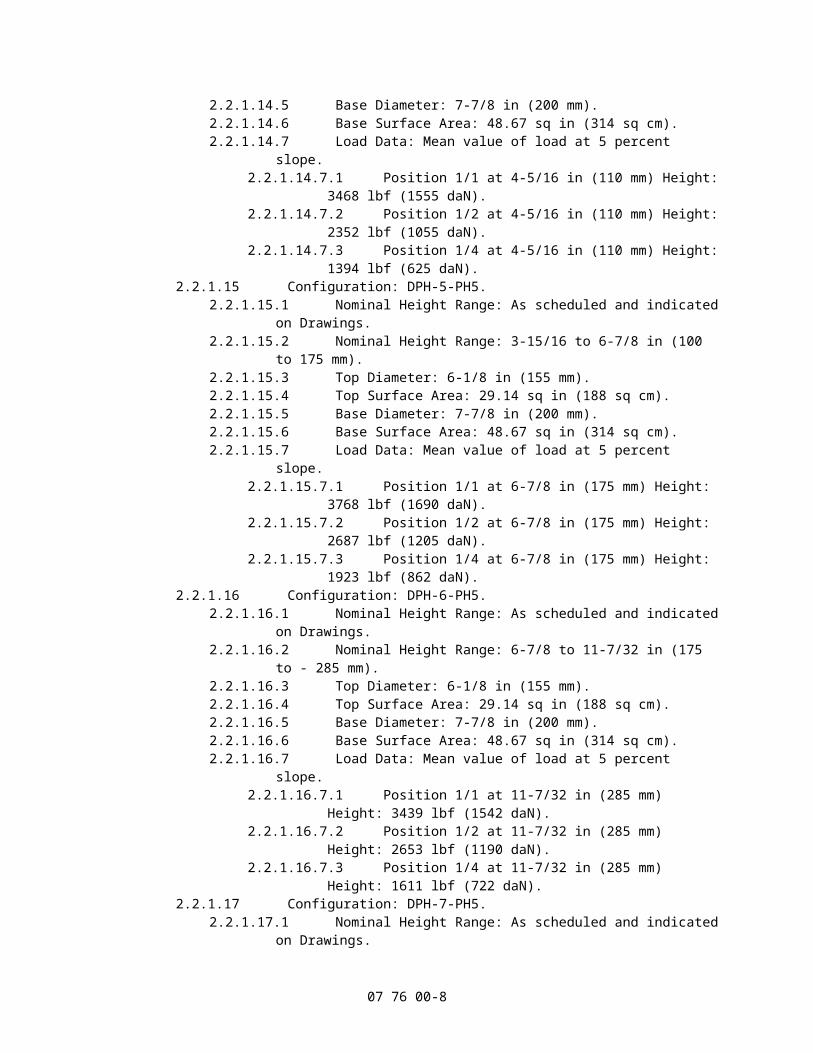
2.2.1.14 Configuration: DPH-4-PH5.2.2.1.14.1 Nominal Height Range: As scheduled and indicated on Drawings.2.2.1.14.2 Nominal Height Range: 3-5/64 to 4-5/16 in (78 to 110 mm).2.2.1.14.3 Top Diameter: 6-1/8 in (155 mm).2.2.1.14.4 Top Surface Area: 29.14 sq in (188 sq cm).2.2.1.14.5 Base Diameter: 7-7/8 in (200 mm).2.2.1.14.6 Base Surface Area: 48.67 sq in (314 sq cm).2.2.1.14.7 Load Data: Mean value of load at 5 percent slope.
2.2.1.14.7.1 Position 1/1 at 4-5/16 in (110 mm) Height: 3468 lbf (1555 daN).2.2.1.14.7.2 Position 1/2 at 4-5/16 in (110 mm) Height: 2352 lbf (1055 daN).2.2.1.14.7.3 Position 1/4 at 4-5/16 in (110 mm) Height: 1394 lbf (625 daN).
2.2.1.15 Configuration: DPH-5-PH5.2.2.1.15.1 Nominal Height Range: As scheduled and indicated on Drawings.2.2.1.15.2 Nominal Height Range: 3-15/16 to 6-7/8 in (100 to 175 mm).2.2.1.15.3 Top Diameter: 6-1/8 in (155 mm).2.2.1.15.4 Top Surface Area: 29.14 sq in (188 sq cm).2.2.1.15.5 Base Diameter: 7-7/8 in (200 mm).
07 76 00-5
2.2.1.15.6 Base Surface Area: 48.67 sq in (314 sq cm).2.2.1.15.7 Load Data: Mean value of load at 5 percent slope.
2.2.1.15.7.1 Position 1/1 at 6-7/8 in (175 mm) Height: 3768 lbf (1690 daN).2.2.1.15.7.2 Position 1/2 at 6-7/8 in (175 mm) Height: 2687 lbf (1205 daN).2.2.1.15.7.3 Position 1/4 at 6-7/8 in (175 mm) Height: 1923 lbf (862 daN).
2.2.1.16 Configuration: DPH-6-PH5.2.2.1.16.1 Nominal Height Range: As scheduled and indicated on Drawings.2.2.1.16.2 Nominal Height Range: 6-7/8 to 11-7/32 in (175 to - 285 mm).2.2.1.16.3 Top Diameter: 6-1/8 in (155 mm).2.2.1.16.4 Top Surface Area: 29.14 sq in (188 sq cm).2.2.1.16.5 Base Diameter: 7-7/8 in (200 mm).2.2.1.16.6 Base Surface Area: 48.67 sq in (314 sq cm).2.2.1.16.7 Load Data: Mean value of load at 5 percent slope.
2.2.1.16.7.1 Position 1/1 at 11-7/32 in (285 mm) Height: 3439 lbf (1542 daN).2.2.1.16.7.2 Position 1/2 at 11-7/32 in (285 mm) Height: 2653 lbf (1190 daN).2.2.1.16.7.3 Position 1/4 at 11-7/32 in (285 mm) Height: 1611 lbf (722 daN).
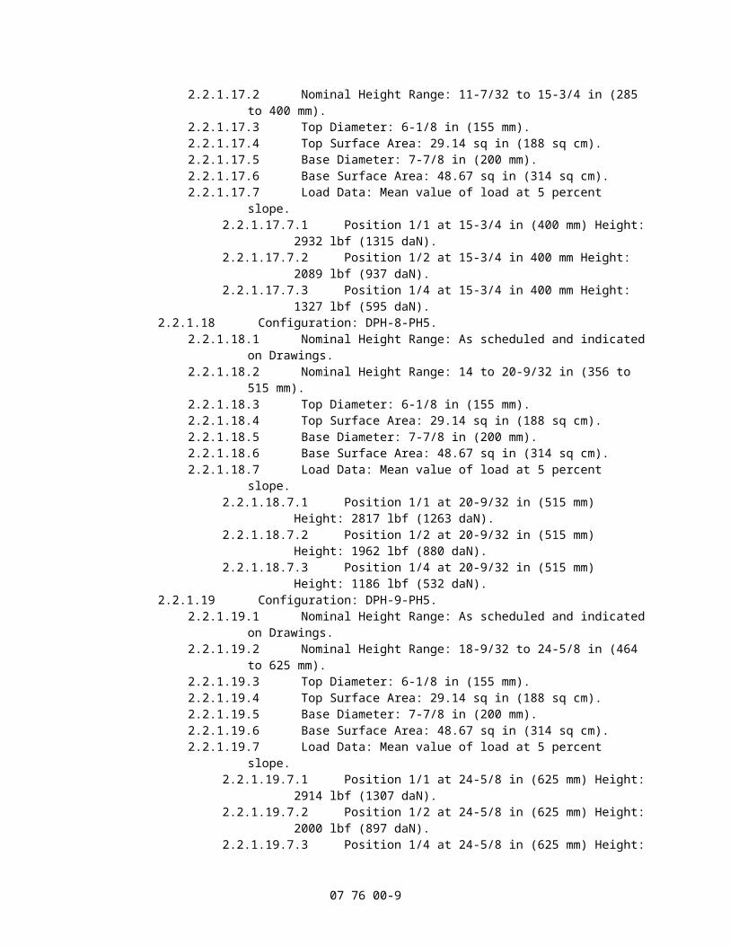
2.2.1.17 Configuration: DPH-7-PH5.2.2.1.17.1 Nominal Height Range: As scheduled and indicated on Drawings.2.2.1.17.2 Nominal Height Range: 11-7/32 to 15-3/4 in (285 to 400 mm).2.2.1.17.3 Top Diameter: 6-1/8 in (155 mm).2.2.1.17.4 Top Surface Area: 29.14 sq in (188 sq cm).2.2.1.17.5 Base Diameter: 7-7/8 in (200 mm).2.2.1.17.6 Base Surface Area: 48.67 sq in (314 sq cm).2.2.1.17.7 Load Data: Mean value of load at 5 percent slope.
2.2.1.17.7.1 Position 1/1 at 15-3/4 in (400 mm) Height: 2932 lbf (1315 daN).2.2.1.17.7.2 Position 1/2 at 15-3/4 in 400 mm Height: 2089 lbf (937 daN).2.2.1.17.7.3 Position 1/4 at 15-3/4 in 400 mm Height: 1327 lbf (595 daN).
2.2.1.18 Configuration: DPH-8-PH5.2.2.1.18.1 Nominal Height Range: As scheduled and indicated on Drawings.2.2.1.18.2 Nominal Height Range: 14 to 20-9/32 in (356 to 515 mm).2.2.1.18.3 Top Diameter: 6-1/8 in (155 mm).2.2.1.18.4 Top Surface Area: 29.14 sq in (188 sq cm).2.2.1.18.5 Base Diameter: 7-7/8 in (200 mm).2.2.1.18.6 Base Surface Area: 48.67 sq in (314 sq cm).2.2.1.18.7 Load Data: Mean value of load at 5 percent slope.
2.2.1.18.7.1 Position 1/1 at 20-9/32 in (515 mm) Height: 2817 lbf (1263 daN).2.2.1.18.7.2 Position 1/2 at 20-9/32 in (515 mm) Height: 1962 lbf (880 daN).2.2.1.18.7.3 Position 1/4 at 20-9/32 in (515 mm) Height: 1186 lbf (532 daN).
2.2.1.19 Configuration: DPH-9-PH5.2.2.1.19.1 Nominal Height Range: As scheduled and indicated on Drawings.2.2.1.19.2 Nominal Height Range: 18-9/32 to 24-5/8 in (464 to 625 mm).2.2.1.19.3 Top Diameter: 6-1/8 in (155 mm).2.2.1.19.4 Top Surface Area: 29.14 sq in (188 sq cm).2.2.1.19.5 Base Diameter: 7-7/8 in (200 mm).2.2.1.19.6 Base Surface Area: 48.67 sq in (314 sq cm).2.2.1.19.7 Load Data: Mean value of load at 5 percent slope.
2.2.1.19.7.1 Position 1/1 at 24-5/8 in (625 mm) Height: 2914 lbf (1307 daN).2.2.1.19.7.2 Position 1/2 at 24-5/8 in (625 mm) Height: 2000 lbf (897 daN).2.2.1.19.7.3 Position 1/4 at 24-5/8 in (625 mm) Height: 1253 lbf (562 daN).
2.2.1.20 Configuration: DPH-10-PH5.2.2.1.20.1 Nominal Height Range: As scheduled and indicated on Drawings.2.2.1.20.2 Nominal Height Range: 21-7/16 to 29-9/64 in (544 to 745 mm).2.2.1.20.3 Top Diameter: 6-1/8 in (155 mm).2.2.1.20.4 Top Surface Area: 29.14 sq in (188 sq cm).2.2.1.20.5 Base Diameter: 7-7/8 in (200 mm).2.2.1.20.6 Base Surface Area: 48.67 sq in (314 sq cm).
07 76 00-6
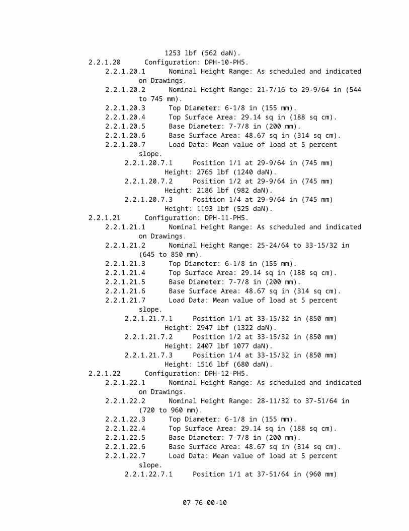
2.2.1.20.7 Load Data: Mean value of load at 5 percent slope.2.2.1.20.7.1 Position 1/1 at 29-9/64 in (745 mm) Height: 2765 lbf (1240 daN).2.2.1.20.7.2 Position 1/2 at 29-9/64 in (745 mm) Height: 2186 lbf (982 daN).2.2.1.20.7.3 Position 1/4 at 29-9/64 in (745 mm) Height: 1193 lbf (525 daN).
2.2.1.21 Configuration: DPH-11-PH5.2.2.1.21.1 Nominal Height Range: As scheduled and indicated on Drawings.2.2.1.21.2 Nominal Height Range: 25-24/64 to 33-15/32 in (645 to 850 mm).2.2.1.21.3 Top Diameter: 6-1/8 in (155 mm).2.2.1.21.4 Top Surface Area: 29.14 sq in (188 sq cm).2.2.1.21.5 Base Diameter: 7-7/8 in (200 mm).2.2.1.21.6 Base Surface Area: 48.67 sq in (314 sq cm).2.2.1.21.7 Load Data: Mean value of load at 5 percent slope.
2.2.1.21.7.1 Position 1/1 at 33-15/32 in (850 mm) Height: 2947 lbf (1322 daN).2.2.1.21.7.2 Position 1/2 at 33-15/32 in (850 mm) Height: 2407 lbf 1077 daN).2.2.1.21.7.3 Position 1/4 at 33-15/32 in (850 mm) Height: 1516 lbf (680 daN).
2.2.1.22 Configuration: DPH-12-PH5.2.2.1.22.1 Nominal Height Range: As scheduled and indicated on Drawings.2.2.1.22.2 Nominal Height Range: 28-11/32 to 37-51/64 in (720 to 960 mm).2.2.1.22.3 Top Diameter: 6-1/8 in (155 mm).2.2.1.22.4 Top Surface Area: 29.14 sq in (188 sq cm).2.2.1.22.5 Base Diameter: 7-7/8 in (200 mm).2.2.1.22.6 Base Surface Area: 48.67 sq in (314 sq cm).2.2.1.22.7 Load Data: Mean value of load at 5 percent slope.
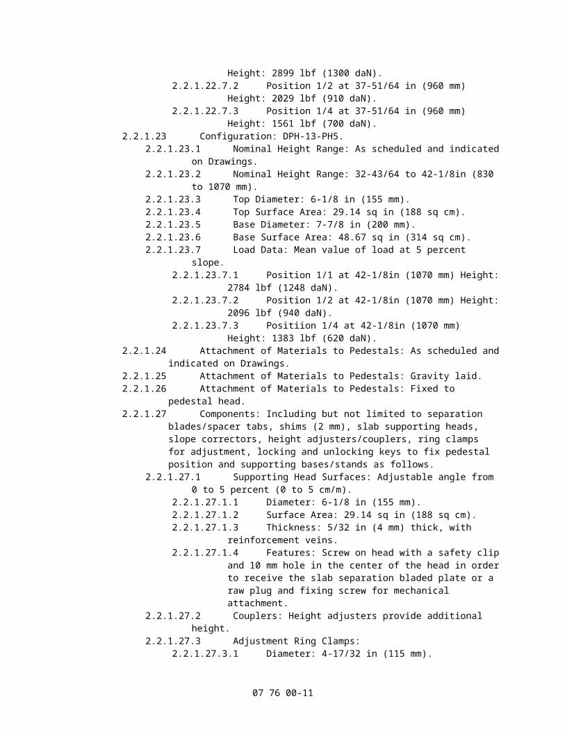
2.2.1.22.7.1 Position 1/1 at 37-51/64 in (960 mm) Height: 2899 lbf (1300 daN).2.2.1.22.7.2 Position 1/2 at 37-51/64 in (960 mm) Height: 2029 lbf (910 daN).2.2.1.22.7.3 Position 1/4 at 37-51/64 in (960 mm) Height: 1561 lbf (700 daN).
2.2.1.23 Configuration: DPH-13-PH5.2.2.1.23.1 Nominal Height Range: As scheduled and indicated on Drawings.2.2.1.23.2 Nominal Height Range: 32-43/64 to 42-1/8in (830 to 1070 mm).2.2.1.23.3 Top Diameter: 6-1/8 in (155 mm).2.2.1.23.4 Top Surface Area: 29.14 sq in (188 sq cm).2.2.1.23.5 Base Diameter: 7-7/8 in (200 mm).2.2.1.23.6 Base Surface Area: 48.67 sq in (314 sq cm).2.2.1.23.7 Load Data: Mean value of load at 5 percent slope.
2.2.1.23.7.1 Position 1/1 at 42-1/8in (1070 mm) Height: 2784 lbf (1248 daN).2.2.1.23.7.2 Position 1/2 at 42-1/8in (1070 mm) Height: 2096 lbf (940 daN).2.2.1.23.7.3 Positiion 1/4 at 42-1/8in (1070 mm) Height: 1383 lbf (620 daN).
2.2.1.24 Attachment of Materials to Pedestals: As scheduled and indicated on Drawings.2.2.1.25 Attachment of Materials to Pedestals: Gravity laid.2.2.1.26 Attachment of Materials to Pedestals: Fixed to pedestal head.2.2.1.27 Components: Including but not limited to separation blades/spacer tabs, shims (2
mm), slab supporting heads, slope correctors, height adjusters/couplers, ring clamps for adjustment, locking and unlocking keys to fix pedestal position and supporting bases/stands as follows.
2.2.1.27.1 Supporting Head Surfaces: Adjustable angle from 0 to 5 percent (0 to 5 cm/m).
2.2.1.27.1.1 Diameter: 6-1/8 in (155 mm).2.2.1.27.1.2 Surface Area: 29.14 sq in (188 sq cm).2.2.1.27.1.3 Thickness: 5/32 in (4 mm) thick, with reinforcement veins.2.2.1.27.1.4 Features: Screw on head with a safety clip and 10 mm hole in the
center of the head in order to receive the slab separation bladed plate or a raw plug and fixing screw for mechanical attachment.
2.2.1.27.2 Couplers: Height adjusters provide additional height.2.2.1.27.3 Adjustment Ring Clamps:
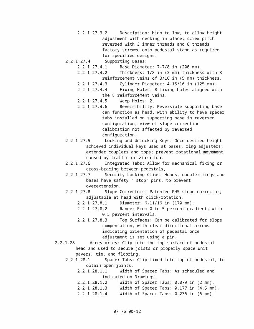
2.2.1.27.3.1 Diameter: 4-17/32 in (115 mm).2.2.1.27.3.2 Description: High to low, to allow height adjustment with decking
07 76 00-7
in place; screw pitch reversed with 3 inner threads and 8 threads factory screwed onto pedestal stand as required for specified designs.
2.2.1.27.4 Supporting Bases:2.2.1.27.4.1 Base Diameter: 7-7/8 in (200 mm).2.2.1.27.4.2 Thickness: 1/8 in (3 mm) thickness with 8 reinforcement veins of
3/16 in (5 mm) thickness.2.2.1.27.4.3 Cylinder Diameter: 4-15/16 in (125 mm).2.2.1.27.4.4 Fixing Holes: 8 fixing holes aligned with the 8 reinforcement veins.2.2.1.27.4.5 Weep Holes: 2.2.2.1.27.4.6 Reversibility: Reversible supporting base can function as head,
with ability to have spacer tabs installed on supporting base in reversed configuration; view of slope correction calibration not affected by reversed configuration.
2.2.1.27.5 Locking and Unlocking Keys: Once desired height achieved individual keys used at bases, ring adjusters, extender couplers and tops; prevent rotational movement caused by traffic or vibration.
2.2.1.27.6 Integrated Tabs: Allow for mechanical fixing or cross-bracing between pedestals,
2.2.1.27.7 Security Locking Clips: Heads, coupler rings and bases have safety ' stop' pins, to prevent overextension.
2.2.1.27.8 Slope Correctors: Patented PH5 slope corrector; adjustable at head with click-rotation.
2.2.1.27.8.1 Diameter: 6-11/16 in (170 mm).2.2.1.27.8.2 Range: From 0 to 5 percent gradient; with 0.5 percent intervals.2.2.1.27.8.3 Top Surfaces: Can be calibrated for slope compensation, with
clear directional arrows indicating orientation of pedestal once adjustment is set using a pin.
2.2.1.28 Accessories: Clip into the top surface of pedestal head and used to secure joists or properly space unit pavers, tie, and flooring.
2.2.1.28.1 Spacer Tabs: Clip-fixed into top of pedestal, to obtain open joints.2.2.1.28.1.1 Width of Spacer Tabs: As scheduled and indicated on Drawings.2.2.1.28.1.2 Width of Spacer Tabs: 0.079 in (2 mm).2.2.1.28.1.3 Width of Spacer Tabs: 0.177 in (4.5 mm).2.2.1.28.1.4 Width of Spacer Tabs: 0.236 in (6 mm).2.2.1.28.1.5 Width of Spacer Tabs: 0.315 in (8 mm).2.2.1.28.1.6 Width of Spacer Tabs: 0.394 in (10 mm).2.2.1.28.1.7 Diameter: 0.315 in (8 mm).
2.2.1.28.2 Rubber Shims: To fit over spacer tabs, made of reinforced (Shore 60) EPDM in 0.04 and 0.08 in (1 and 2 mm) thicknesses.
2.2.1.28.3 Joist Cradles: Supports joists for timber-style decking.2.2.1.28.3.1 Description: Compatible with timber battens/joists, composite
battens/joists, aluminum or steel support sections; with fixing holes on both sides of support for mechanical fixing
2.2.1.28.3.2 Width of Support: Up to 2-9/16 in (65 mm).
2.2.2 Basis of Design: PB Series Screwjack Pedestals, as manufactured by Buzon.2.2.2.1 Pedestal Component Materials: Talc-loaded polypropylene copolymer with 80
percent recycled CCP material, 20 percent Talc plus UV, Master Batch black, 100 percent recyclable. Temperature Range: Suitable for use from minus 22 to 194 degrees F (minus 30 to 90 degrees C).
2.2.2.2 Pedestal Component Materials: As scheduled and indicated on Drawings.2.2.2.3 Pedestal Component Materials: ______.2.2.2.4 Ancillary Application Materials:
2.2.2.4.1 Accommodates metal grid systems, fiberglass grid systems, timber-style decking, square-shaped or rectangular-shaped stone, concrete, natural
07 76 00-8
stone, terrazzo, ceramic, composite pavers as approved by manufacturer.2.2.2.4.2 Do not use Buzon Deck Supports over insulation less than 20 psi or with
low density polystyrene insulation.2.2.2.5 Compliance:
2.2.2.5.1 Testing Agency: Belgium (CRIF) Centre De Recherches Scientifiques ET Techniques Del Industrie Des Fabrications.
2.2.2.5.2 Test Method: Universal testing machine, Instron type.2.2.2.5.3 Test Report: No. GT 7660/01.2.2.2.5.4 Safety Factor for Pedestrian Terraces: Divide "Load Data" by 2 with an
additional safety factor of 15 percent.2.2.2.5.5 Safety Factor for Raised False Floors: Divide "Load Data" by 4 with an
additional safety factor of 15 percent.2.2.2.6 Configuration: As scheduled and indicated on Drawings2.2.2.7 Configuration: PB-00.
2.2.2.7.1 Nominal Fixed Height: As scheduled and indicated on Drawings.2.2.2.7.2 Nominal Fixed Height: 19/32 in (15 mm).2.2.2.7.3 Nominal Fixed Height with BC-PH5 Slope Corrector: 1-1/32 in (26 mm).
2.2.2.8 Configuration: PB-01.2.2.2.8.1 Nominal Height Range: As scheduled and indicated on Drawings.2.2.2.8.2 Nominal Height Range: 1-1/8 to 1-5/8 in (28 to 41 mm).2.2.2.8.3 Nominal Height Range with BC-PH5 Slope Corrector: 1-9/16 to 2-1/8 in (37
to 54 mm).2.2.2.8.4 Base Diameter: 7-3/4 in (197 mm).2.2.2.8.5 Base Surface Area: 47.17 sq in (304 sq cm).2.2.2.8.6 Base Diameter with BC-PH5 Slope Corrector: 8-1/16 in (205 mm).2.2.2.8.7 Base Surface Area with BC-PH5 Slope Corrector: 51.06 sq in (329 sq cm).2.2.2.8.8 Top Diameter: 6-11/16 in (170 mm).2.2.2.8.9 Top Surface Area: 35.12 sq in (227 sq cm).2.2.2.8.10 Load Data: Mean value of load at 1-5/8 in (41 mm) height.
2.2.2.8.10.1 Position 1/1: 1877 lbf (842 daN)).2.2.2.8.10.2 Position 1/2: 1171 lbf (525 daN).2.2.2.8.10.3 Position 1/4: 762 lbf (342 daN)
2.2.2.9 Configuration: PB-1.2.2.2.9.1 Nominal Height Range: As scheduled and indicated on Drawings.2.2.2.9.2 Nominal Height Range: 1-21/32 to 2-3/8 (42 to 60 mm).2.2.2.9.3 Nominal Height Range with BC-PH5 Slope Corrector: 2-3/16 to 2-7/8 in (26
to 73 mm)2.2.2.9.4 Base Diameter: 7-3/4 in (197 mm).2.2.2.9.5 Base Surface Area: 47.17 sq in (304 sq cm).2.2.2.9.6 Base Diameter with BC-PH5 Slope Corrector: 8-1/16 in (205 mm).2.2.2.9.7 Base Surface Area with BC-PH5 Slope Corrector: 51.06 sq in (329 sq cm).2.2.2.9.8 Top Diameter: 6-11/16 in (170 mm).2.2.2.9.9 Top Surface Area: 35.12 sq in (227 sq cm).2.2.2.9.10 Load Data: Mean value of load at 5 percent slope, 2-3/8 in (60 mm) height.
2.2.2.9.10.1 Position 1/1: 3200 lbf (1435 daN).2.2.2.9.10.2 Position 1/2: 1769 lbf (793 daN).2.2.2.9.10.3 Position 1/4: 1232 lbf (553 (daN).
2.2.2.10 Configuration: PB-2.2.2.2.10.1 Nominal Height Range: As scheduled and indicated on Drawings.2.2.2.10.2 Nominal Height Range: 2-23/64 to 3-9/16 in (60 to 90 mm).2.2.2.10.3 Nominal Height Range with BC-PH5 Slope Corrector: 2-13/16 to 4 in (71 to
102 mm).2.2.2.10.4 Base Diameter: 7-3/4 in (197 mm).2.2.2.10.5 Base Surface Area: 47.17 sq in (304 sq cm).2.2.2.10.6 Base Diameter with BC-PH5 Slope Corrector: 8-1/16 in (205 mm).2.2.2.10.7 Base Surface Area with BC-PH5 Slope Corrector: 51.06 sq in (329 sq cm).
07 76 00-9
2.2.2.10.8 Top Diameter: 6-11/16 in (170 mm).2.2.2.10.9 Top Surface Area: 35.12 sq in (227 sq cm).2.2.2.10.10 Load Data: Mean value of load at 5 percent slope, 3-9/16 in (90 mm)
height.2.2.2.10.10.1 Position 1/1: 3732 lbf (1673 daN).2.2.2.10.10.2 Position 1/2: 2115 lbf (948 daN).2.2.2.10.10.3 Position 1/4: 1171 lbf (525 daN).
2.2.2.11 Configuration: PB-3.2.2.2.11.1 Nominal Height Range: As scheduled and indicated on Drawings.2.2.2.11.2 Nominal Height Range: 3-9/16 to 5-11/16 in (90 to 145 mm).2.2.2.11.3 Nominal Height Range with BC-PH5 Slope Corrector: 4 to 6-3/16 in (102 to
157 mm).2.2.2.11.4 Base Diameter: 7-3/4 in (197 mm).2.2.2.11.5 Base Surface Area: 47.17 sq in (304 sq cm).2.2.2.11.6 Base Diameter with BC-PH5 Slope Corrector: 8-1/16 in (205 mm).2.2.2.11.7 Base Surface Area with BC-PH5 Slope Corrector: 51.06 sq in (329 sq cm).2.2.2.11.8 Top Diameter: 6-11/16 in (170 mm).2.2.2.11.9 Top Surface Area: 35.12 sq in (227 sq cm).2.2.2.11.10 Load Data: Mean value of load at 5 percent slope, 5-11/16 in (145 mm)
height.2.2.2.11.10.1 Position 1/1: 3531 lbf (1583 daN).2.2.2.11.10.2 Position 1/2: 2495 lbf (1119 daN).2.2.2.11.10.3 Position 1/4: 1319 lbf (592 daN).
2.2.2.12 Configuration: PB-4.2.2.2.12.1 Nominal Height Range: As scheduled and indicated on Drawings.2.2.2.12.2 Nominal Height Range: 5-11/16 to 9-5/8 in (145 to 245 mm).2.2.2.12.3 Nominal Height Range with BC-PH5 Slope Corrector: 6-3/16 to 10-1/8 in
(157 to 275 mm).2.2.2.12.4 Base Diameter: 7-3/4 in (197 mm).2.2.2.12.5 Base Surface Area: 47.17 sq in (304 sq cm).2.2.2.12.6 Base Diameter with BC-PH5 Slope Corrector: 8-1/16 in (205 mm).2.2.2.12.7 Base Surface Area with BC-PH5 Slope Corrector: 51.06 sq in (329 sq cm).2.2.2.12.8 Top Diameter: 6-11/16 in (170 mm).2.2.2.12.9 Top Surface Area: 35.12 sq in (227 sq cm).2.2.2.12.10 Load Data: Mean value of load at 5 percent slope, 9-5/8 in (245 mm)
height.2.2.2.12.10.1 Position 1/1: 3365 lbf (1509 daN).2.2.2.12.10.2 Position 1/2: 2527 lbf (1133 daN).2.2.2.12.10.3 Position 1/4: 1279 lbf (573 daN).
2.2.2.13 Configuration: PB-5.2.2.2.13.1 Nominal Height Range: As scheduled and indicated on Drawings.2.2.2.13.2 Nominal Height Range: 9-1/16 to 12-3/8 in (230 to 314 mm).2.2.2.13.3 Nominal Height Range with BC-PH5 Slope Corrector: 9-1/2 to 12-7/8 in
(241 to 327 mm).2.2.2.13.4 Base Diameter: 7-3/4 in (197 mm).2.2.2.13.5 Base Surface Area: 47.17 sq in (304 sq cm).2.2.2.13.6 Base Diameter with BC-PH5 Slope Corrector: 8-1/16 in (205 mm).2.2.2.13.7 Base Surface Area with BC-PH5 Slope Corrector: 51.06 sq in (329 sq cm).2.2.2.13.8 Top Diameter: 6-11/16 in (170 mm).2.2.2.13.9 Top Surface Area: 35.12 sq in (227 sq cm).2.2.2.13.10 Load Data: Mean value of load at 5 percent slope, 12-3/8 in (314 mm)
height.2.2.2.13.10.1 Position 1/1: 2312 lbf (1037 daN).2.2.2.13.10.2 Position 1/2: 2159 lbf (968 daN).2.2.2.13.10.3 Position 1/4: 1208 lbf (542 daN).
2.2.2.14 Configuration: PB-6.
07 76 00-10
2.2.2.14.1 Nominal Height Range: As scheduled and indicated on Drawings.2.2.2.14.2 Nominal Height Range: 11-1/4 to 14-7/16 in (286 to 367 mm).2.2.2.14.3 Nominal Height Range with BC-PH5 Slope Corrector: 11-11/16 to 14-15/16
in (297 to 379 mm).2.2.2.14.4 Base Diameter: 7-3/4 in (197 mm).2.2.2.14.5 Base Surface Area: 47.17 sq in (304 sq cm).2.2.2.14.6 Base Diameter with BC-PH5 Slope Corrector: 8-1/16 in (205 mm).2.2.2.14.7 Base Surface Area with BC-PH5 Slope Corrector: 51.06 sq in (329 sq cm).2.2.2.14.8 Top Diameter: 6-11/16 in (170 mm).2.2.2.14.9 Top Surface Area: 35.12 sq in (227 sq cm).2.2.2.14.10 Load Data: Mean value of load at 5 percent slope, 14-7/16 in (367 mm)
height.2.2.2.14.10.1 Position 1/1: 2315 lbf (1038 daN).2.2.2.14.10.2 Position 1/2: 2152 lbf (965 daN).2.2.2.14.10.3 Position 1/4: 1468 lbf (658 daN).
2.2.2.15 Configuration: PB-7.2.2.2.15.1 Nominal Height Range: As scheduled and indicated on Drawings.2.2.2.15.2 Nominal Height Range: 14-3/8 to 19-1/8 in (365 to 486).2.2.2.15.3 Nominal Height Range with BC-PH5 Slope Corrector: 14-13/16 to 19-9/16
in (376 to 497 mm).2.2.2.15.4 Base Diameter: 7-3/4 in (197 mm).2.2.2.15.5 Base Surface Area: 47.17 sq in (304 sq cm).2.2.2.15.6 Base Diameter with BC-PH5 Slope Corrector: 8-1/16 in (205 mm).2.2.2.15.7 Base Surface Area with BC-PH5 Slope Corrector: 51.06 sq in (329 sq cm).2.2.2.15.8 Top Diameter: 6-11/16 in (170 mm).2.2.2.15.9 Top Surface Area: 35.12 sq in (227 sq cm).2.2.2.15.10 Load Data: Mean value of load at 5 percent slope, 19-1/8 in (486 mm)
height.2.2.2.15.10.1 Position 1/1: 2167 lbf (972 daN).2.2.2.15.10.2 Position 1/2: 1940 lbf (870 daN).2.2.2.15.10.3 Position 1/4: 1412 lbf (633 daN).
2.2.2.16 Configuration: PB-8.2.2.2.16.1 Nominal Height Range: As scheduled and indicated on Drawings.2.2.2.16.2 Nominal Height Range: 17-13/16 to 23-13/16 in (452 to 605).2.2.2.16.3 Nominal Height Range with BC-PH5 Slope Corrector: 18-1/4 to 24-5/16
(464 to 618 mm).2.2.2.16.4 Base Diameter: 7-3/4 in (197 mm).2.2.2.16.5 Base Surface Area: 47.17 sq in (304 sq cm).2.2.2.16.6 Base Diameter with BC-PH5 Slope Corrector: 8-1/16 in (205 mm).2.2.2.16.7 Base Surface Area with BC-PH5 Slope Corrector: 51.06 sq in (329 sq cm).2.2.2.16.8 Top Diameter: 6-11/16 in (170 mm).2.2.2.16.9 Top Surface Area: 35.12 sq in (227 sq cm).2.2.2.16.10 Load Data: Mean value of load at 5 percent slope, 23-13/16 in (605 mm).
height.2.2.2.16.10.1 Position 1/1: 2089 lbf (937 daN).2.2.2.16.10.2 Position 1/2: 1936 lbf (868 daN).2.2.2.16.10.3 Position 1/4: 1461 lbf (655 daN).
2.2.2.17 Configuration: PB-9.2.2.2.17.1 Nominal Height Range: As scheduled and indicated on Drawings.2.2.2.17.2 Nominal Height Range: 21-1/8 to 28-9/16 in (537 to 725 mm).2.2.2.17.3 Nominal Height Range with BC-PH5 Slope Corrector: 21-5/8 to 29 in (549
to 737 mm).2.2.2.17.4 Base Diameter: 7-3/4 in (197 mm).2.2.2.17.5 Base Surface Area: 47.17 sq in (304 sq cm).2.2.2.17.6 Base Diameter with BC-PH5 Slope Corrector: 8-1/16 in (205 mm).2.2.2.17.7 Base Surface Area with BC-PH5 Slope Corrector: 51.06 sq in (329 sq cm).
07 76 00-11
2.2.2.17.8 Top Diameter: 6-11/16 in (170 mm).2.2.2.17.9 Top Surface Area: 35.12 sq in (227 sq cm).2.2.2.17.10 Load Data: Mean value of load at 5 percent slope, 28-9/16 in (725 mm)
height.2.2.2.17.10.1 Position 1/1: 2040 lbf (915 daN).2.2.2.17.10.2 Position 1/2: 1922 lbf (862 daN).2.2.2.17.10.3 Position 1/4: 1516 lbf (680 daN).
2.2.2.18 Configuration: PB-10.2.2.2.18.1 Nominal Height Range: As scheduled and indicated on Drawings.2.2.2.18.2 Nominal Height Range: 29-7/16 to 33-1/4 in (748 to 845 mm).2.2.2.18.3 Nominal Height Range with BC-PH5 Slope Corrector: 24-7/8 to 33-3/4 in
(632 to 857 mm).2.2.2.18.4 Base Diameter: 7-3/4 in (197 mm).2.2.2.18.5 Base Surface Area: 47.17 sq in (304 sq cm).2.2.2.18.6 Base Diameter with BC-PH5 Slope Corrector: 8-1/16 in (205 mm).2.2.2.18.7 Base Surface Area with BC-PH5 Slope Corrector: 51.06 sq in (329 sq cm).2.2.2.18.8 Top Diameter: 6-11/16 in (170 mm).2.2.2.18.9 Top Surface Area: 35.12 sq in (227 sq cm).2.2.2.18.10 Load Data: Mean value of load at 5 percent slope, 33-1/4 in (845 mm)
height.2.2.2.18.10.1 Position 1/1: 2033 lbf (912 daN).2.2.2.18.10.2 Position 1/2: 1829 lbf (820 daN).2.2.2.18.10.3 Position 1/4: 1141 lbf (512 daN).
2.2.2.19 Configuration: PB-11.2.2.2.19.1 Nominal Height Range: As scheduled and indicated on Drawings.2.2.2.19.2 Nominal Height Range: 27-3/4 to 38 in (705 to 965 mm).2.2.2.19.3 Nominal Height Range with BC-PH5 Slope Corrector:28-3/16 to 38-7/16
(716 to 976 mm).2.2.2.19.4 Base Diameter: 7-3/4 in (197 mm).2.2.2.19.5 Base Surface Area: 47.17 sq in (304 sq cm).2.2.2.19.6 Base Diameter with BC-PH5 Slope Corrector: 8-1/16 in (205 mm).2.2.2.19.7 Base Surface Area with BC-PH5 Slope Corrector: 51.06 sq in (329 sq cm).2.2.2.19.8 Top Diameter: 6-11/16 in (170 mm).2.2.2.19.9 Top Surface Area: 35.12 sq in (227 sq cm).2.2.2.19.10 Load Data: Mean value of load at 5 percent slope, 38 in (965 mm) height.
2.2.2.19.10.1 Position 1/1: 1933 lbf (867 daN).2.2.2.19.10.2 Position 1/2: 1609 lbf (722 daN).2.2.2.19.10.3 Position 1/4: 1208 lbf (542 daN).
2.2.2.20 Attachment of Materials to Pedestals: As scheduled and indicated on Drawings.2.2.2.21 Attachment of Materials to Pedestals: Gravity laid.2.2.2.22 Attachment of Materials to Pedestals: Fixed to pedestal head.2.2.2.23 Components: Including but not limited to spacer tabs, batten holders, slope
correctors, height adjusting couplers, locking and unlocking keys to fix pedestal position and supporting bases/stands as follows.
2.2.2.23.1 Cylindrical Supporting Heads:2.2.2.23.1.1 Thickness: 0.196 in (5 mm).2.2.2.23.1.2 Top Diameter: 6-11/16 in (170 mm).2.2.2.23.1.3 Top Surface Area: 35.185 sq in (227 sq cm).2.2.2.23.1.4 Design: Continuously threaded over its full height, screws into
pedestal base sleeve or coupler. Head surface has threaded and slotted holes to receive and secure battens, paver separators, joist supports and utility supports. A security clip indicates the height adjustment limit and prevents total separation.
2.2.2.23.2 Cylindrical Supporting Bases:2.2.2.23.2.1 Base Diameter: 7-3/4 in (197 mm).2.2.2.23.2.2 Base Surface Area: 47.275 sq in (305 sq cm).
07 76 00-12
2.2.2.23.2.3 Thickness: 1/8 in (3 mm) thickness with 8 reinforcement veins of 3/16 in (5 mm) thickness.
2.2.2.23.2.4 Cylinder Diameter: ______.2.2.2.23.2.5 Fixing Holes: 8 fixing holes aligned with the 8 reinforcement veins.2.2.2.23.2.6 Weep Holes: 2.
2.2.2.23.3 Sleeves: Type C1-PB4 couplers provide additional height; for adjustments from 9-1/16 to 37-63/64 in (230 to 965 mm).
2.2.2.23.3.1 Thickness: Manufacturer's standard thickness.2.2.2.23.3.2 Cylinder Diameter: 5-1/8 in (130 mm).2.2.2.23.3.3 Lower Part of Cylinders: Multi-threaded, screws into pedestal base
or another sleeve. A safety clip to prevent total unscrewing.2.2.2.23.3.4 Upper Part of Cylinders: Threads for receiving pedestal heads or
additional sleeves. A safety clip prevents total unscrewing of pedestal head or sleeve.
2.2.2.23.3.5 Locking/Adjustment:2.2.2.23.3.5.1 On upper cylinder of sleeve are two lock and unlock
orifices providing access to two lock keys to lock up pedestal head or sleeves after height adjustment of pedestal head or screwed sleeves.
2.2.2.23.3.5.2 Upper and external part of sleeve has a small hole into which pointed end of nail can be inserted to unlock the safety clip, thereby allowing head to be unscrewed in order to fit one or more additional sleeves.
2.2.2.23.4 Slope Correctors: Patented BC-PH5 slope correctors.2.2.2.23.4.1 Mounting: Under pedestal head in direct contact with sloping
ground.2.2.2.23.4.2 Application: Used in combination with circular and rectangular
tabs.2.2.2.23.4.3 Design: Consists of two cylinders, factory assembled.2.2.2.23.4.4 Thickness of Elements: 1/8 to 3/16 in (3 to 5 mm).2.2.2.23.4.5 Disc External Diameter: 10-1/32 in (225 mm).2.2.2.23.4.6 Assembly thickness at 0 percent: 1/2 in (13 mm) to be added to
the pedestal height.2.2.2.23.4.7 Assembly thickness at 5 percent: 23/32 in (18 mm) to be added to
the pedestal height.2.2.2.23.4.8 Function:
2.2.2.23.4.8.1 Allows slopes from 0 to 5 percent with 0.5 percent intervals.
2.2.2.23.4.8.2 Two BC-PH5 correctors allow slopes of up to 10 percent to be corrected.
2.2.2.23.4.8.3 The two cylinders are adjustable through 360 degrees; a pin holds the value in place and prevents both cylinders from moving.
2.2.2.23.4.8.4 The correct slope value can be viewed through an oval reading window.
2.2.2.23.4.8.5 Positioned in direction of slope to be corrected with aid of indicator arrow printed on lower plate of corrector with same value of upper plate.
2.2.2.23.4.8.6 The pedestal, mounted on slope corrector, will then be horizontal in all directions with respect to the slope to be offset.
2.2.2.23.5 Integrated Tabs: Allow for mechanical fixing or cross-bracing, between pedestals.
2.2.2.23.6 Security Locking Clips: Heads, coupler rings and bases have safety ' stop' pins, to prevent overextension.
2.2.2.24 Accessories: Clip into the top surface of pedestal head and used to secure joists or properly space unit pavers, tie, and flooring.
07 76 00-13
2.2.2.24.1 Aluminum Batten Holders.2.2.2.24.2 Adjustable Wood Batten Holders.2.2.2.24.3 Fixed Wood Batten Holders.2.2.2.24.4 Tile Separator: Four 3/16 in (5 mm) wide tabs on cross that snaps onto top
surface.2.2.2.24.5 Tile Separator: Four 1/8: in (3 mm) wide tabs on cross that snaps onto top
surface.2.2.2.24.6 Tile Separator: Four 1/16 in (1.5 mm) wide tabs on cross that snaps onto
top surface.2.2.2.25 EPDM Shims: To fit over spacer tabs, made of reinforced (Shore 60) EPDM in
0.04 and 0.08 in (1 and 2 mm) thicknesses.2.2.2.26 PB-SHIMS-4MM: Manufacturer's standard units.
2.2.3 Basis of Design: BC Series Screwjack Pedestals, as manufactured by Buzon.2.2.3.1 Pedestal Component Materials: Talc-loaded polypropylene copolymer with
minimum 78 percent recycled CCP material, 20 percent Talc, 2 percent UV, Master Batch black, 100 percent recyclable; suitable for use in temperatures from minus 22 to 194 degrees F (minus 30 to 90 degrees C) except as indicated.
2.2.3.2 Pedestal Component Materials: As scheduled and indicated on Drawings.2.2.3.3 Pedestal Component Materials: ______.2.2.3.4 Ancillary Application Materials: Do not use over insulation less than 20 psi or
with low density polystyrene insulation.2.2.3.5 System Design and Compatibility: Circular or rectangular separator tabs on
pedestal heads for accessible terraces, green terraces or raised floors; compatible pavers shapes including but not limited too triangular, pentagonal, hexagonal, circular, square and rectangular pavers.
2.2.3.6 Compliance:2.2.3.6.1 Testing Agency: Belgium (CRIF) Centre De Recherches Scientifiques ET
Techniques Del Industrie Des Fabrications.2.2.3.6.2 Test Method: Universal testing machine, Instron type.2.2.3.6.3 Test Report: No. GT 7660/01.2.2.3.6.4 Safety Factor for Pedestrian Terraces: Divide "Load Data" by 2 with an
additional safety factor of 15 percent.2.2.3.6.5 Safety Factor for Raised False Floors: Divide "Load Data" by 4 with an
additional safety factor of 15 percent.2.2.3.7 Configuration: As scheduled and indicated on Drawings.2.2.3.8 Configuration: BC-0-NA.
2.2.3.8.1 Nominal Fixed Height: As scheduled and indicated on Drawings.2.2.3.8.2 Nominal Fixed Height: 7/16 in (11 mm).2.2.3.8.3 Nominal Fixed Height with BC-PH5 Slope Corrector: 7/8 in (22 mm).2.2.3.8.4 Base Diameter: 7-7/8 in (200 mm).2.2.3.8.5 Base Surface Area: 48.71 sq in (314.3 sq cm).2.2.3.8.6 Base Diameter with BC-PH5 Slope Corrector: 8 in (203 mm).2.2.3.8.7 Base Surface Area with BC-PH5 Slope Corrector: 50.26 sq in (325 sq cm).2.2.3.8.8 Load Data: Mean value of load at 7/16 in (11 mm) height.
2.2.3.8.8.1 Position 1/1: 4817 lbf (2160 daN).2.2.3.8.8.2 Position 1/2: 3523 lbf (1580 daN).2.2.3.8.8.3 Position 1/4: 1817 lbf (815 daN).
2.2.3.9 Configuration: BC-1-NA.2.2.3.9.1 Nominal Fixed Height: As scheduled and indicated on Drawings.2.2.3.9.2 Nominal Fixed Height: 9/16 in (14 mm).2.2.3.9.3 Nominal Fixed Height with BC-PH5 Slope Corrector, 1 in (25 mm).2.2.3.9.4 Base Diameter: 7-78 in (200 mm).2.2.3.9.5 Base Surface Area: 48.71 sq in (314.3 sq cm).2.2.3.9.6 Base Diameter with BC-PH5 Slope Corrector: 8 in (203 mm).2.2.3.9.7 Base Surface Area with BC-PH5 Slope Corrector: 50.26 sq in (325 sq cm).
07 76 00-14
2.2.3.9.8 Load Data: Mean value of load at 9/16 in (14 mm) height.2.2.3.9.8.1 Position 1/1: 21854 lbf (9800 daN).2.2.3.9.8.2 Position 1/2: 15781 lbf (7077 daN).2.2.3.9.8.3 Position 1/4: 7054 lbf (3163 daN).
2.2.3.10 Configuration: BC-02-SC.2.2.3.10.1 Nominal Height Range: As scheduled and indicated on Drawings.2.2.3.10.2 Nominal Height Range: 1-1/8 to 1-5/8 in (29 to 41 mm).2.2.3.10.3 Nominal Height Range with BC-PH5 Slope Corrector: 1 5/8 to 2 in (41 to
51 mm).2.2.3.10.4 Base Diameter: 7-78 in (200 mm).2.2.3.10.5 Base Surface Area: 48.71 sq in (314.3 sq cm).2.2.3.10.6 Base Diameter with BC-PH5 Slope Corrector: 8 in (203 mm).2.2.3.10.7 Base Surface Area with BC-PH5 Slope Corrector: 50.26 sq in (325 sq cm).2.2.3.10.8 Top Diameter: 5-11/16 in (145 mm).2.2.3.10.9 Top Surface Area: 25.41 sq in (163.89 sq cm).2.2.3.10.10 Load Data: Mean value of load at 1-5/8 in (41 mm) height.
2.2.3.10.10.1 Position 1/1: 2278 lb (1022 daN).2.2.3.10.10.2 Position 1/2: 1464 lbf (657 daN).2.2.3.10.10.3 Position 1/4: 928 lbf (416416 daN).
2.2.3.11 Configuration: BC-2-SC.2.2.3.11.1 Nominal Height Range: As scheduled and indicated on Drawings.2.2.3.11.2 Nominal Height Range: 1-5/8 to 2-3/16 in (41 to 55 mm).2.2.3.11.3 Nominal Height Range with BC-PH5 Slope Corrector: 2 to 2-5/8 in (51 to
67 mm).2.2.3.11.4 Base Diameter: 7-78 in (200 mm).2.2.3.11.5 Base Surface Area: 48.71 sq in (314.3 sq cm).2.2.3.11.6 Base Diameter with BC-PH5 Slope Corrector: 8 in (203 mm).2.2.3.11.7 Base Surface Area with BC-PH5 Slope Corrector: 50.26 sq in (325 sq cm).2.2.3.11.8 Top Diameter: 5-11/16 in (145 mm).2.2.3.11.9 Top Surface Area: 25.41 sq in (163.89 sq cm).2.2.3.11.10 Load Data: Mean value of load at 2-3/16 in (55 mm) height.
2.2.3.11.10.1 Position 1/1: 3653 lbf (1638 daN).2.2.3.11.10.2 Position 1/2: 2401 lbf(1077 daN).2.2.3.11.10.3 Position 1/4: 1680 lbf (753 daN).
2.2.3.12 Configuration: BC-3-SC.2.2.3.12.1 Nominal Height Range: As scheduled and indicated on Drawings.2.2.3.12.2 Nominal Height Range: 2-3/16 to 3-3/8 in (55 to 85 mm).2.2.3.12.3 Nominal Height Range with BC-PH5 Slope Corrector: 2-5/8 to 3-13/16 in
(67 to 97 mm).2.2.3.12.4 Base Diameter: 7-78 in (200 mm).2.2.3.12.5 Base Surface Area: 48.71 sq in (314.3 sq cm).2.2.3.12.6 Base Diameter with BC-PH5 Slope Corrector: 8 in (203 mm).2.2.3.12.7 Base Surface Area with BC-PH5 Slope Corrector: 50.26 sq in (325 sq cm).2.2.3.12.8 Top Diameter: 5-11/16 in (145 mm).2.2.3.12.9 Top Surface Area: 25.41 sq in (163.89 sq cm).2.2.3.12.10 Load Data: Mean value of load at 5 percent slope, 3-3/8 in (85 mm)
height.2.2.3.12.10.1 Position 1/1: 2854 lbf (1280 daN).2.2.3.12.10.2 Position 1/2: 1981 lbf (888 daN).2.2.3.12.10.3 Position 1/4: 1312 lbf (588 daN).
2.2.3.13 Configuration: BC-4-SC.2.2.3.13.1 Nominal Height Range: As scheduled and indicated on Drawings.2.2.3.13.2 Nominal Height Range: 3-3/8 to 5-1/2 (85 to 140 mm).2.2.3.13.3 Nominal Height Range with BC-PH5 Slope Corrector: 3-13/16 to 5-15/16 in
(97 to 151 mm).2.2.3.13.4 Base Diameter: 7-78 in (200 mm).
07 76 00-15
2.2.3.13.5 Base Surface Area: 48.71 sq in (314.3 sq cm).2.2.3.13.6 Base Diameter with BC-PH5 Slope Corrector: 8 in (203 mm).2.2.3.13.7 Base Surface Area with BC-PH5 Slope Corrector: 50.26 sq in (325 sq cm).2.2.3.13.8 Top Diameter: 5-11/16 in (145 mm).2.2.3.13.9 Top Surface Area: 25.41 sq in (163.89 sq cm).2.2.3.13.10 Load Data: Mean value of load at 5 percent slope, 5-1/2 in (140 mm)
height.2.2.3.13.10.1 Position 1/1: 3304 lbf (1482 daN).2.2.3.13.10.2 Position 1/2: 2501 lbf (1122 daN).2.2.3.13.10.3 Position 1/4: 1635 lbf (733 daN).
2.2.3.14 Configuration: BC-5-SC.2.2.3.14.1 Nominal Height Range: As scheduled and indicated on Drawings.2.2.3.14.2 Nominal Height Range: 4-9/16 to 7-7/8 in (116 to 200 mm).2.2.3.14.3 Nominal Height Range with BC-PH5 Slope Corrector: 5 to 8-5/16 in (127 to
211 mm)2.2.3.14.4 Base Diameter: 7-78 in (200 mm).2.2.3.14.5 Base Surface Area: 48.71 sq in (314.3 sq cm).2.2.3.14.6 Base Diameter with BC-PH5 Slope Corrector: 8 in (203 mm).2.2.3.14.7 Base Surface Area with BC-PH5 Slope Corrector: 50.26 sq in (325 sq cm).2.2.3.14.8 Top Diameter: 5-11/16 in (145 mm).2.2.3.14.9 Top Surface Area: 25.41 sq in (163.89 sq cm).2.2.3.14.10 Load Data: Mean value of load at 5 percent slope, 7-7/8 in (200 mm)
height.2.2.3.14.10.1 Position 1/1: 2877 lbf (1290 daN).2.2.3.14.10.2 Position 1/2: 2119 lbf (950 daN).2.2.3.14.10.3 Position 1/4: 1327 lbf (595 daN).
2.2.3.15 Configuration: BC-6-INV.2.2.3.15.1 Nominal Height Range: As scheduled and indicated on Drawings.2.2.3.15.2 Nominal Height Range: 7-13/16 to 13 3/8 in (198 to 340 mm).2.2.3.15.3 Nominal Height Range with BC-PH5 Slope Corrector: 8-2/4 to 13-13/16 in
(210 to 351 mm)2.2.3.15.4 Base Diameter: 7-78 in (200 mm).2.2.3.15.5 Base Surface Area: 48.71 sq in (314.3 sq cm).2.2.3.15.6 Base Diameter with BC-PH5 Slope Corrector: 8 in (203 mm).2.2.3.15.7 Base Surface Area with BC-PH5 Slope Corrector: 50.26 sq in (325 sq cm).2.2.3.15.8 Top Diameter: 5-11/16 in (145 mm).2.2.3.15.9 Top Surface Area: 25.41 sq in (163.89 sq cm).2.2.3.15.10 Load Data: Mean value of load at 5 percent slope, 13 3/8 in (340 mm)
height.2.2.3.15.10.1 Position 1/1: 2649 lbf (1188 daN).2.2.3.15.10.2 Position 1/2: 2386 lbf (1070 daN).2.2.3.15.10.3 Position 1/4: 1434 lbf (643 daN).
2.2.3.16 Configuration: BC-7-NSC.2.2.3.16.1 Nominal Height Range: As scheduled and indicated on Drawings.2.2.3.16.2 Nominal Height Range: 8-13/16 to 14-3/8 in (224 to 365 mm).2.2.3.16.3 Nominal Height Range with BC-PH5 Slope Corrector: 9.25 to 14-13/16 in
(235 to 376 mm)2.2.3.16.4 Base Diameter: 7-78 in (200 mm).2.2.3.16.5 Base Surface Area: 48.71 sq in (314.3 sq cm).2.2.3.16.6 Base Diameter with BC-PH5 Slope Corrector: 8 in (203 mm).2.2.3.16.7 Base Surface Area with BC-PH5 Slope Corrector: 50.26 sq in (325 sq cm).2.2.3.16.8 Top Diameter: 5-11/16 in (145 mm).2.2.3.16.9 Top Surface Area: 25.41 sq in (163.89 sq cm).2.2.3.16.10 Load Data: Mean value of load at 5 percent slope, 14-3/8 in (365 mm)
height.2.2.3.16.10.1 Position 1/1: 3189 lbf (1430 daN).
07 76 00-16
2.2.3.16.10.2 Position 1/2: 2557 lbf (1147 daN).2.2.3.16.10.3 Position 1/4: 1713 lbf (768 daN).
2.2.3.17 Configuration: BC-8-INV.2.2.3.17.1 Nominal Height Range: As scheduled and indicated on Drawings.2.2.3.17.2 Nominal Height Range: 13 to 20-7/8 in (330 to 530 mm).2.2.3.17.3 Nominal Height Range with BC-PH5 Slope Corrector: 13-7/16 to 21-5/16 in
(341 to 541 mm).2.2.3.17.4 Base Diameter: 7-78 in (200 mm).2.2.3.17.5 Base Surface Area: 48.71 sq in (314.3 sq cm).2.2.3.17.6 Base Diameter with BC-PH5 Slope Corrector: 8 in (203 mm).2.2.3.17.7 Base Surface Area with BC-PH5 Slope Corrector: 50.26 sq in (325 sq cm).2.2.3.17.8 Top Diameter: 5-11/16 in (145 mm).2.2.3.17.9 Top Surface Area: 25.41 sq in (163.89 sq cm).2.2.3.17.10 Load Data: Mean value of load at 5 percent slope, 20-7/8 in (530 mm)
height.2.2.3.17.10.1 Position 1/1: 2743 lbf (1230 daN).2.2.3.17.10.2 Position 1/2: 2327 lbf (1043 daN).2.2.3.17.10.3 Position 1/4: 1777 lbf (797 daN).
2.2.3.18 Configuration: BC-9-INV.2.2.3.18.1 Nominal Height Range: As scheduled and indicated on Drawings.2.2.3.18.2 Nominal Height Range: 17-3/16 to 27-1/2 in (437 to 698 mm).2.2.3.18.3 Nominal Height Range with BC-PH5 Slope Corrector: 17-5/8 to 27-15/16 in
(448 to 710 mm).2.2.3.18.4 Base Diameter: 7-78 in (200 mm).2.2.3.18.5 Base Surface Area: 48.71 sq in (314.3 sq cm).2.2.3.18.6 Base Diameter with BC-PH5 Slope Corrector: 8 in (203 mm).2.2.3.18.7 Base Surface Area with BC-PH5 Slope Corrector: 50.26 sq in (325 sq cm).2.2.3.18.8 Top Diameter: 5-11/16 in (145 mm).2.2.3.18.9 Top Surface Area: 25.41 sq in (163.89 sq cm).2.2.3.18.10 Load Data: Mean value of load at 5 percent slope, 27-1/2 in (698 mm)
height.2.2.3.18.10.1 Position 1/1: 2847 lbf (1277 daN).2.2.3.18.10.2 Position 1/2: 2282 lbf (1023 daN).2.2.3.18.10.3 Position 1/4: 1613 lbf (723 daN).
2.2.3.19 Configuration: BC-10-INV.2.2.3.19.1 Nominal Height Range: As scheduled and indicated on Drawings.2.2.3.19.2 Nominal Height Range: 21-7/16 to 34 in (545 to 864 mm).2.2.3.19.3 Nominal Height Range with BC-PH5 Slope Corrector: 21-7/8 to 34-7/16
(556 to 875 mm).2.2.3.19.4 Base Diameter: 7-78 in (200 mm).2.2.3.19.5 Base Surface Area: 48.71 sq in (314.3 sq cm).2.2.3.19.6 Base Diameter with BC-PH5 Slope Corrector: 8 in (203 mm).2.2.3.19.7 Base Surface Area with BC-PH5 Slope Corrector: 50.26 sq in (325 sq cm).2.2.3.19.8 Top Diameter: 5-11/16 in (145 mm).2.2.3.19.9 Top Surface Area: 25.41 sq in (163.89 sq cm).2.2.3.19.10 Load Data: Mean value of load at 5 percent slope, 34 in (864 mm) height.
2.2.3.19.10.1 Position 1/1: 2669 lbf (1197 daN).2.2.3.19.10.2 Position 1/2: 2044 lbf (917 daN).2.2.3.19.10.3 Position 1/4: 1383 lbf (620 daN).
2.2.3.20 Configuration: BC-11-INV.2.2.3.20.1 Nominal Height Range: As scheduled and indicated on Drawings.2.2.3.20.2 Nominal Height Range: 25-11/16 to 40-9/16 in (653 to 1030 mm).2.2.3.20.3 Nominal Height Range with BC-PH5 Slope Corrector: 26-1/8 to 41 (664 to
1041 mm)2.2.3.20.4 Base Diameter: 7-78 in (200 mm).2.2.3.20.5 Base Surface Area: 48.71 sq in (314.3 sq cm).
07 76 00-17
2.2.3.20.6 Base Diameter with BC-PH5 Slope Corrector: 8 in (203 mm).2.2.3.20.7 Base Surface Area with BC-PH5 Slope Corrector: 50.26 sq in (325 sq cm).2.2.3.20.8 Top Diameter: 5-11/16 in (145 mm).2.2.3.20.9 Top Surface Area: 25.41 sq in (163.89 sq cm).2.2.3.20.10 Load Data: Mean value of load at 5 percent slope, 40-9/16 in (130 mm)
height.2.2.3.20.10.1 Position 1/1: 2598 lbf (1165 daN).2.2.3.20.10.2 Position 1/2: 2078 lbf (532 daN).2.2.3.20.10.3 Position 1/4: 1371 lbf (615 daN).
2.2.3.21 Attachment of Materials to Pedestals: As scheduled and indicated on Drawings.2.2.3.22 Attachment of Materials to Pedestals: Gravity laid.2.2.3.23 Attachment of Materials to Pedestals: Fixed to pedestal head.2.2.3.24 Components: Including but not limited to separation blades/spacer tabs, slab
supporting heads, slope correctors, height adjusters/couplers, locking and unlocking keys to fix pedestal position and supporting bases/stands as follows.
2.2.3.24.1 Cylindrical Supporting Heads:2.2.3.24.1.1 Thickness: 0.196 in (5 mm).2.2.3.24.1.2 Diameter: 6-1/8 in (155 mm).2.2.3.24.1.3 Surface Area: 29.14 sq in (188 sq cm).2.2.3.24.1.4 Reinforcement: Under surface of pedestal head, 14 ribs per head.2.2.3.24.1.5 Design: Continuously threaded over its full height, screws into
pedestal base sleeve. On top of base of threaded part of head is a safety clip to prevent total unscrewing, so that three safety threads are retained at all times.
2.2.3.24.1.6 Surface of Pedestal Head:2.2.3.24.1.6.1 On Periphery:
2.2.3.24.1.6.1.1 12 circular holes for fixing circular spacer tabs of 5/64 in (2 mm), 11/64 (4.5 mm), 15/64 in (6 mm), 5/16 in (8 mm), or 25/64 in (10 mm) thickness.
2.2.3.24.1.6.1.2 Allows angles of 30 degrees, 45 degrees, 60 degrees, 90 degrees,120 degrees, 145 degrees, 150 degrees and 180 degrees to be obtained; for use with triangular, pentagonal, hexagonal, circular, square, rectangular pavers or pavers of different shapes.
2.2.3.24.1.6.2 At Center:2.2.3.24.1.6.2.1 4 rectangular holes receiving rectangular spacer
tabs of 5/64 in (2 mm), 11/64 (4.5 mm), 15/64 in (6 mm), 5/16 in (8 mm), or 25/64 in (10 mm) thickness, for use with square or rectangular pavers.
2.2.3.24.1.6.2.2 Fitted with a 9/16 in (14 mm) threaded hole for screw or bolt fixing or for fixing of a batten support.
2.2.3.24.1.6.2.3 4 circular 15/32 in (12 mm) threaded holes for screw or bolt fixing or for mounting circular tabs for 45 degree or 145 degree angles.
2.2.3.24.2 Cylindrical Supporting Bases:2.2.3.24.2.1 Base Type: Type BC-4, adjustable from 3-11/32 to 5-1/2 n (85 to
140 mm).2.2.3.24.2.2 Base Type: Type BC-5, adjustable from 4-9/16 to 7-7/8 in (116 to
200 mm).2.2.3.24.2.3 Base Diameter: 8-1/16 in (205 mm).2.2.3.24.2.4 Cylinder Diameter: 4-15/16 in (125 mm).2.2.3.24.2.5 Thickness: 5/32 in (4 mm) thickness.2.2.3.24.2.6 Reinforcement: 8 reinforcement veins of 1/8 in (3 mm) thickness.2.2.3.24.2.7 Fixing Holes: Aligned with reinforcement veins.2.2.3.24.2.8 Weep Holes: 2 per base.2.2.3.24.2.9 Inside of Cylinders: Fitted with 4 clamping threads to receive
07 76 00-18
heads, sleeves.2.2.3.24.2.10 Internal Cylinders: Equipped with a safety orifice (hole) to
prevent total unscrewing of pedestal head.2.2.3.24.2.11 Edges: Rounded to prevent degradation of support substrate.2.2.3.24.2.12 Drainage:
2.2.3.24.2.12.1 At end of external and internal cylinder are orifices to allow proper rainwater drainage, preventing stagnation.
2.2.3.24.2.12.2 Interconnected drainage channels are provided under pedestal base.
2.2.3.24.2.13 Base Flange: 8 holes on periphery aligned with 8 reinforcement ribs to allow bases to be fixed to concrete, epoxy, wood or steel support substrates.
2.2.3.24.2.14 Locking/Adjustment: Provided with two holes for access to two lock keys arranged so as to lock bases, heads and sleeves after height adjustment; pointed end of nail can be inserted to unlock safety clip on pedestal head, thereby allowing pedestal head to be unscrewed in order to fit one or more additional sleeves; up to a max height of 4-9/16 in (1030 mm).
2.2.3.24.3 Sleeves: Type C3-BC couplers provide additional height; for adjustments from 7-7/8 to 40-9/16 in (200 to 1030 mm).
2.2.3.24.3.1 Thickness: 5/32 in (4 mm).2.2.3.24.3.2 Cylinder Diameter: 4-18 in (105 mm).2.2.3.24.3.3 Design: Fitted with 2 cylinders, injection molded in one piece.2.2.3.24.3.4 Lower Part of Cylinders: Multi-threaded lower part of cylinder
screws into pedestal base and has a safety clip to prevent total unscrewing.
2.2.3.24.3.5 Upper Part of Cylinders: 4 threads for receiving pedestal heads or additional sleeves, and safety clip to prevent total unscrewing of pedestal head or sleeve.
2.2.3.24.3.6 Reinforcement:2.2.3.24.3.6.1 4 vertical reinforcement bars on the outside.2.2.3.24.3.6.2 1/8 in (3 mm) thick plate with reinforcement bars at
center of internal cylinder.2.2.3.24.3.7 Drainage: Plate at center of internal cylinders fitted with 8 holes to
ensure proper rainwater drainage.2.2.3.24.3.8 Locking/Adjustment:
2.2.3.24.3.8.1 On upper cylinder of sleeve are two lock and unlock orifices providing access to two lock keys to lock up pedestal head or sleeves after height adjustment of pedestal head or screwed sleeves.
2.2.3.24.3.8.2 Upper and external part of sleeve has a small hole into which pointed end of nail can be inserted to unlock the safety clip, thereby allowing head to be unscrewed in order to fit one or more additional sleeves.
2.2.3.24.4 Spacer Tabs: Clip-fixed into top of pedestal, to obtain open joints.2.2.3.24.4.1 Attachment: Mechanically fixed to pedestal head by clicking them
into place.2.2.3.24.4.2 Spacer Tabs Type: As scheduled and indicated on Drawings.2.2.3.24.4.3 Spacer Tabs Type: Circular.
2.2.3.24.4.3.1 Circular tabs with cylindrical base allow 360 degrees' rotation on pedestal head for 30 degree, 45 degree, 60 degree, 90 degree, 120 degree, 145 degree, 150 degree or 180 degree angles.
2.2.3.24.4.3.2 Can be rotated to adapt to angle of triangular, circular, pentagonal, hexagonal, square, rectangular pavers or pavers of different shapes.
07 76 00-19
2.2.3.24.4.4 Spacer Tabs Type: Rectangular.2.2.3.24.4.4.1 Tabs with rectangular bases allow fixed mounting on
pedestal head for 90 degree or 180 degree angles; used for applications with square or rectangular pavers.
2.2.3.24.4.5 Width of Spacer Tabs: As scheduled and indicated on Drawings.2.2.3.24.4.6 Width of Spacer Tabs: 5/64 in (2 mm).2.2.3.24.4.7 Width of Spacer Tabs: 13/64 in (4.5 mm).2.2.3.24.4.8 Width of Spacer Tabs: 1/4 in (6 mm).2.2.3.24.4.9 Width of Spacer Tabs: 5/16 in (8 mm).2.2.3.24.4.10 Width of Spacer Tabs: 13/32 in (10 mm).
2.2.3.24.5 Locking and Unlocking Keys: Patented system.2.2.3.24.5.1 Materials: PA-Nylon.2.2.3.24.5.2 Design: In upper and external part of pedestal base and in sleeves
are two lock and unlock orifices providing access to two lock keys, which are arranged so as to lock the pedestal heads after height adjustment.
2.2.3.24.5.3 Function:2.2.3.24.5.3.1 Pointed end of nail can be inserted to unlock safety clips.2.2.3.24.5.3.2 Locks pedestal heads in pedestal bases.2.2.3.24.5.3.3 Locks pedestal heads in the sleeves.2.2.3.24.5.3.4 Locks sleeves in pedestal bases.2.2.3.24.5.3.5 Interlocks sleeves screwed into each other.
2.2.3.24.6 Slope Correctors: Patented PH5 slope corrector; adjustable at head with click-rotation.
2.2.3.24.6.1 Application: Used only with rectangular shaped tabs.2.2.3.24.6.2 Design: Consists of two cylinders, factory assembled;
compensates for horizontal slopes allowing level surface above pedestal heads.
2.2.3.24.6.3 Diameter: 6-1/8 in (155 mm).2.2.3.24.6.4 Thickness: 1/8 to 3/16 (3 mm to 5 mm).2.2.3.24.6.5 Disc External Diameter: 6-1/8 in (155 mm) for mounting on top of
the pedestal heads.2.2.3.24.6.6 Assembly Thickness at 0 percent: 1/2 in (13 mm) to be added to
the pedestal height.2.2.3.24.6.7 Assembly thickness at 5 percent: 23/32 in (18 mm) to be added to
the pedestal height.2.2.3.24.6.8 Function:
2.2.3.24.6.8.1 Adapted to head of pedestal, upper cylinder is adjustable through 360 degrees to find correct slope value, viewable through oval reading window; allows slopes from 0 to 5 percent with 0.5 percent intervals.
2.2.3.24.6.8.2 Pin holds chosen value in place, prevents both cylinders from moving.
2.2.3.24.6.8.3 Can rotate on pedestal head to enable it to be placed in correct slope direction by means of an arrow indicating value of selected slope.
2.2.3.24.6.8.4 Complete pedestal assembly is then positioned in direction of slope to be corrected with aid of indicator arrow printed on plate of the corrector with the value of the slope to be corrected.
2.2.3.24.6.8.5 Pedestal will then be horizontal in with respect to slope to be offset.
2.2.3.24.7 Slope Correctors: Patented BC-PH5 slope correctors.2.2.3.24.7.1 Mounting: Under pedestal head in direct contact with sloping
ground.2.2.3.24.7.2 Application: Used in combination with circular and rectangular
07 76 00-20
tabs.2.2.3.24.7.3 Design: Consists of two cylinders, factory assembled.2.2.3.24.7.4 Thickness of Elements: 1/8 to 3/16 in (3 to 5 mm).2.2.3.24.7.5 Disc External Diameter: 10-1/32 in (225 mm).2.2.3.24.7.6 Assembly thickness at 0 percent: 1/2 in (13 mm) to be added to
the pedestal height.2.2.3.24.7.7 Assembly thickness at 5 percent: 23/32 in (18 mm) to be added to
the pedestal height.2.2.3.24.7.8 Function:
2.2.3.24.7.8.1 Allows slopes from 0 to 5 percent with 0.5 percent intervals.
2.2.3.24.7.8.2 Two BC-PH5 correctors allow slopes of up to 10 percent to be corrected.
2.2.3.24.7.8.3 The two cylinders are adjustable through 360 degrees; a pin holds the value in place and prevents both cylinders from moving.
2.2.3.24.7.8.4 The correct slope value can be viewed through an oval reading window.
2.2.3.24.7.8.5 Positioned in direction of slope to be corrected with aid of indicator arrow printed on lower plate of corrector with same value of upper plate.
2.2.3.24.7.8.6 The pedestal, mounted on slope corrector, will then be horizontal in all directions with respect to the slope to be offset.
2.2.3.24.8 Reverse Couplers: C4-BC-INV adjustable by 1-1/5 (32 mm).2.2.3.24.8.1 Thickness: 3/16 in (5 mm).2.2.3.24.8.2 External Diameter: 4-1/8 in (105 mm).2.2.3.24.8.3 Design: Coupler with reverse threading consists of two cylinders
with multiple inner and outer threads, factory assembled; clicks into base of pedestal type BC-4 or BC-5.
2.2.3.24.8.4 Function:2.2.3.24.8.4.1 Pedestal heads BC-4 or BC-5 and sleeves can be
screwed completely into the upper part of the reverse coupler.2.2.3.24.8.4.2 For use with pedestal type BC-4 for adjustment from 7-
29/32 to 9-1/16 in (198 to 230 mm).2.2.3.24.8.4.3 Mounting: On top of last sleeve to facilitate fine height
adjustment of the pedestal head by plus 1-1/4 in (32 mm) under pavers, gratings, raised floors or wood strip surfaces and for green terrace gratings.
2.2.3.24.8.5 Fitted with safety system to prevent total unscrewing, so that at least 3 clamping threads are retained at all times.
2.2.3.24.8.6 Two parts of reverse coupler have 3/16 in (5 mm) thick plate on the inside to rigidly attach them together.
2.2.3.24.8.7 Drainage: Plate on inside fitted with holes to ensure proper rainwater drainage.
2.2.3.24.8.8 Locking: Upper part of reverse coupler has a small hole into which pointed end of nail can be inserted to unlock safety clip; allows unscrewing pedestal head.
2.2.3.24.9 Batten Holders: Batten support plate.2.2.3.24.9.1 Application: For wooden or composite terrace decks placed and
mounted on battens.2.2.3.24.9.2 Thickness: 7/16 in (11 mm).2.2.3.24.9.3 Adjustment: Provided with adjustment guides from 1-3/8 to 3-9/16
in (35 to 90 mm) and more, for receiving battens of different shapes and thicknesses; battens fastened to adjustment guides with stainless steel screws.
2.2.3.24.9.4 Dimensions: Square-shaped plates, 6-1/16 x 6-1/16 in (154 x 154
07 76 00-21
mm).2.2.3.24.9.5 Components: 7 parts per plate.
2.2.3.24.9.5.1 1 rectangular plate.2.2.3.24.9.5.2 4 adjustment guides in Polypropylene for fixing the
battens.2.2.3.24.9.5.3 2 clamping clips in POM for fixing batten plate to
pedestal heads.2.2.3.24.9.6 Plate Surfaces:
2.2.3.24.9.6.1 Surface Area: 37.2 sq in (240 sq cm).2.2.3.24.9.6.2 Reinforcement: Slots, 1/8 in (3 mm) in thickness.2.2.3.24.9.6.3 Mountings: Center of plate is 19/32 in (15 mm) diameter
hole for mounting 2 fixing clips on pedestal heads.2.2.3.24.9.6.4 4 slots 2-15/16 in (75 mm) in length for receiving the 4
adjustment guides.2.2.3.24.9.7 Adjustment Guides: Click into slots of plates.
2.2.3.24.9.7.1 Shape: Triangular shaped parts.2.2.3.24.9.7.2 Dimensions: 1-3/16 x 1-31/32 x 1-3/8 in (30 x 50 x 35
mm).2.2.3.24.9.7.3 Adjustment Guides: Can receive battens thicknesses 1-
3/8 in (35 mm), 1-9/16 in (40 mm), 1-25/32 in (045 mm), 1-31/32 in (50 mm), 2-5/32 in (055 mm), 2-3/8 in (60 mm), 2-9/16 in (65 mm), 2-3/4 in (70 mm), 2-31/32 in (75 mm), 3-1/8 in (80 mm), 3-11/32 in (85 mm), 3-35/64 in (90 mm) thick and more; consult manufacturer for details.
2.2.3.24.10 Joist Cradles: Supports joists for timber-style decking.2.2.3.24.10.1 Description: Compatible with timber battens/joists, composite
battens/joists, aluminum or steel support sections; with fixing holes on both sides of support for mechanical fixing.
2.2.3.24.10.2 Width of Supports: Up to 2-9/16 in (65 mm).2.2.3.24.11 Acoustical Suppression Shims: EPDM, 50 shore, 0.04 and 0.08 in (1 and
2 mm).
3 EXECUTION
3.1 EXAMINATION AND PREPARATION
3.1.1 Prepare substrates using the methods recommended by the manufacturer for achieving best result for the substrates under project conditions. Verify elevations, pedestal heights and layouts. Establish accurate and level lines and patterns.3.1.1.1 Substrate Requirements: Laid at ground or roof level over concrete, screed,
EPDM, rubber, single ply or other built up roofing systems, or directly over insulation materials, dependent on insulation densities and overall loadings.
3.1.2 Do not proceed with installation until substrates have been prepared using the methods recommended by the manufacturer and deviations from manufacturer's recommended tolerances are corrected. Commencement of installation constitutes acceptance of conditions.
3.1.3 If preparation is the responsibility of another installer, notify Architect in writing of deviations from manufacturer's recommended installation tolerances and conditions.
3.2 INSTALLATION
3.2.1 Install products in accordance with manufacturer's instructions.3.2.1.1 For Water Run-Off: Minimum slope of 2 percent.3.2.1.2 Larger Applications: Manufacturer recommends pedestals be pre-sorted and
pre-set to proper elevation and placed in position prior to installation of decking.
07 76 00-22
3.2.1.3 Limitations: Pedestal system shall not be used for decks over which wheeled or vibrating machinery are to be used.
3.2.1.4 Point Loads: Such as planters, seating, furniture or heavy objects should be supported by additional pedestals.
3.2.2 Perimeter Containment: Sections of decking not restrained by parapet or foundation wall must be ' boxed-in' and contained by manufacturer approved perimeter containment.
3.3 ADJUSTMENT AND PROTECTION
3.3.1 Adjustment: Eliminate rocking and uneven pavers; rotate pedestals for final adjustment after fully loaded.
3.3.2 Touch-up, repair or replace damaged products before Substantial Completion.
3.3.3 Protection: Protect installed products and finishes from damage during construction.
END OF SECTION
07 76 00-23