Embed Size (px)
Citation preview
USER MANUALPM Series
Cabinet: PM3340-520KVA, PM3340-400KVAPM3340-320KVA, PM3340-200KVA
Model: PM3340-RM
UDD-SD-125

USER MANUALUSER MANUAL
PM SeriesCabinet: PM3340-520KVA, PM3340-400KVA
PM3340-320KVA, PM3340-200KVAModel: PM3340-RM
All rights reserved.The information in this document is subject to change without notice.
Publish statementThank you for purchasing this series UPS.This series UPS is an intelligent, three phase in Three phase out, high frequency online UPS designed by our R&D team who is with years of designing experiences on UPS. With excellent electrical performance, perfect intelligent monitoring and network functions, smart appearance, complying with EMC and safety standards, The UPS meets the world’s advanced level. Read this manual carefully before installationThis manual provides technical support to the operator of the equipment.

About The Manual
This manual is prepared for the users of "Cabinet: PM3340-520KVA, PM3340-400KVA, PM3340-320KVA, PM3340-200KVA - Model: PM3340-RM"
Companion Manuals
For further information about this device and its options, please visit www.makelsan.com.tr
Updates
Please visit www.makelsan.com.tr for updates. Always use the latest manuals.
PM SERIES CONTENTS
CONTENTS
1 SAFETY.................................................................................................................................................................................. 4
1.1 Safety Notes................................................................................................................................................................ 4
1.2 Symbols Used in This Guide.................................................................................................................................4
2 MAIN FEATURES...............................................................................................................................................................5
2.1 Summarization.......................................................................................................................................................... 5
2.2 Functions and Features.....................................................................................................................................5
3 INSTALLATION..................................................................................................................................................................7
3.1 Unpack Checking...................................................................................................................................................... 7
3.2 The Appearance of the Product..........................................................................................................................7
3.3 UPS Module Appearance....................................................................................................................................13
3.4 UPS Module LCD Control Panel.......................................................................................................................14
3.5 Installation Notes...................................................................................................................................................15
3.6 External Protective Devices..............................................................................................................................16
3.7 Power Cables........................................................................................................................................................... 16
3.8 Power Cable Connect...........................................................................................................................................17
3.9 Battery Connection...............................................................................................................................................19
3.10 Online UPS Modules Replacement..............................................................................................................20
3.11 UPS Multi-Module Installation......................................................................................................................21
3.11.1 Cabinet Installation........................................................................................................................................21
3.11.2 Parallel Cable Installation............................................................................................................................22
3.12 LBS Installation....................................................................................................................................................22
3.12.1 LCD Setting.........................................................................................................................................................22
3.12.2 LBS Cable Installation....................................................................................................................................22
3.12.3 UPS Installation................................................................................................................................................23
4 OPERATION...................................................................................................................................................................... 24
4.1 Operation Modes....................................................................................................................................................24
4.2 Turn on/off UPS..................................................................................................................................................... 25
4.2.1 Restart Procedure..............................................................................................................................................25
4.2.2 Test Procedure....................................................................................................................................................26
4.2.3 Cold Start Procedure........................................................................................................................................26
4.2.4 Maintenance Bypass.........................................................................................................................................27
4.2.5 Shut Down Procedure......................................................................................................................................28
4.2.6 Startup Procedure for Parallel System.....................................................................................................28
PM SERIES CONTENTS
4.3 The Display...............................................................................................................................................................29
4.3.1 System LCD Display..........................................................................................................................................29
4.3.2 UPS Module LCD Display................................................................................................................................37
4.3.3 Monitoring Module Control Panel..............................................................................................................42
4.4 Display Messages/Troubleshooting..............................................................................................................44
4.5 Options....................................................................................................................................................................... 50
Appendix 1 Specifications..........................................................................................................................................51
Appendix 2 UPS message table...............................................................................................................................53
Appendix 3 Problems and Solution......................................................................................................................57
Appendix 4 RS232 communication port definition....................................................................................59
Appendix 5 RS485 communication port definition....................................................................................60
Appendix 6 BAT_T communication port definition....................................................................................61
Appendix 7 Drycontact port definition..............................................................................................................62
Appendix 8 REPO instruction..................................................................................................................................62
Appendix 9 LBS communication port definition..........................................................................................63
5 GUARANTEE.....................................................................................................................................................................64
5.1 Terms of Guarantee..............................................................................................................................................64
5.2 Cases Not Covered by the Guarantee............................................................................................................65
6 CONTACT INFORMATION..........................................................................................................................................69
PM SERIES
1 SAFETY
Important safety instructions - Save these instructions
There exists dangerous voltage and high temperature inside the UPS. During the installation,
operation and maintenance, please abide the local safety instructions and relative laws,
otherwise it will result in personnel injury or equipment damage. Safety instructions in this
manual act as a supplementary for the local safety instructions. Our company will not assume
the liability that caused by disobeying safety instructions.
1.1 Safety Notes
1. Even no connection with utility power, 220/230/240VAC voltage may still exist at UPS outlet!
2. For the sake of human being safety, please well earth the UPS before starting it.
3. Don’t open or damage battery, for the liquid spilled from the battery is strongly poisonous
and do harmful to body!
4. Please avoid short circuit between anode and cathode of battery, otherwise, it will cause
spark or fire!
5. Don’t disassemble the UPS cover, or there may be an electric shock!
6. Check if there exists high voltage before touching the battery
7. Working environment and storage way will affect the lifetime and reliability of the UPS. Avoid
the UPS from working under following environment for long time
Area where the humidity and temperature is out of the specified range (temperature 0 to
40℃, relative humidity 5%-95%)
Direct sunlight or location nearby heat
Vibration Area with possibility to get the UPS crashed.
Area with erosive gas, flammable gas, excessive dust, etc
8. Keep ventilations in good conditions otherwise the components inside the UPS will be over-heated which may affect the life of the UPS.
1.2 Symbols Used in This Guide
WARNING!
Risk of electric shock
CAUTION!
Read this information to avoid equipment damage
UDD-SD-125/ Release Date: 20.01.2015/Rev No: 0/Rev. Date:4
PM SERIES
2 MAIN FEATURES
2.1 Summarization
Our UPS is a kind of three-in- three -out high frequency online UPS, it provides three specifications: The 200kVA/320kVA and 520kVA. The products are modularized and adopt the N+X redundancy. It can flexibly increase the number of the UPS modules according to the load capacity which is convenient for flexible allocation and gradually investment.
The UPS can solve most of the power supply problems, such as blackout, over-voltage, under-voltage, voltage sudden drop, oscillating of decreasing extent, high voltage pulse, voltage fluctuation, surge, inrush current, harmonic distortion (THD), noise interference, frequency fluctuation, etc..
This UPS can be applied to different applications from computer device, automatic equipment, communication system to industry equipment
2.2 Functions and Features
Digital control
19-inch standard cabinet
1.6-meter and 2-meter high cabinets are provided according to the user’s requirement.
Modularized design
High power-density design
The height of the single module is 3U
N+X parallel redundancy
This series UPS adopts N+X parallel redundancy design, user can set different redundancy
according to the importance of the load. While the redundancy modules are set more than two,
the availability of UPS system will achieve 99.999%, which may satisfy the required reliability of
the critical load connected. Through LCD display setting, you may configure the required
quantity of the redundancy unit. When the load connected is over the number of the
redundancy, the UPS will alert right away. The design of the MTBF (Meantime before Failure) is
up to 250,000 hours.
UDD-SD-125/ Release Date: 20.01.2015/Rev No: 0/Rev. Date:5
PM SERIES
This series can set the number of redundancy modules. When the load exceeds the redundancy
setting, the UPS can still work normally and simultaneously send out corresponding warning as
long as the load doesn’t exceed the total capacity of modules.
Parallel redundant control system
Optimizing distributed convergence for the cabinet
Separated Bypass
Common Battery
Automatic charge current adjustment according to battery capacity connected.
3-Stage intelligent charging
Touch-screen Super-large LCD display (Optional)
Each module with individual LCD display
Remote monitoring via SNMP
Optional Accessories available such as Isolation transformer, Distribution Panel, SNMP Card,
Relay Contact Board, etc...
Equip with Maintenance Bypass Switch for easy maintenance purpose.
Superior MTTR (Meantime to repair) & Short shutdown time in maintenance
Centralized monitoring module is also available
EPO and REPO function
UDD-SD-125/ Release Date: 20.01.2015/Rev No: 0/Rev. Date:6
PM SERIES
3 INSTALLATION
3.1 Unpack Checking
1. Don’t lean the UPS when moving it out from the packaging
2. Check the appearance to see if the UPS is damaged or not during the transportation, do not
switch on the UPS if any damage found. Please contact the dealer right away.
3. Check the accessories according to the packing list and contact the dealer in case of missing
parts.
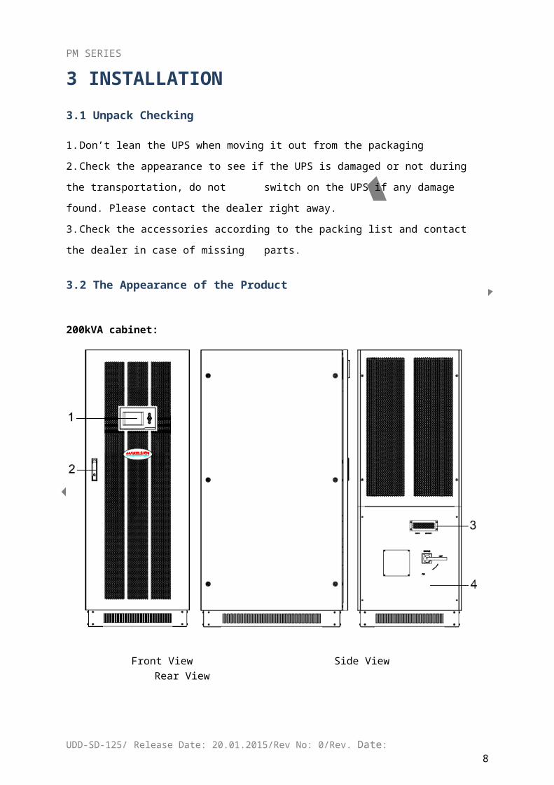
3.2 The Appearance of the Product
200kVA cabinet:
Front View Side View Rear View
UDD-SD-125/ Release Date: 20.01.2015/Rev No: 0/Rev. Date:7
PM SERIES
Front View (internal) Rear View (internal)
UDD-SD-125/ Release Date: 20.01.2015/Rev No: 0/Rev. Date:8
PM SERIES
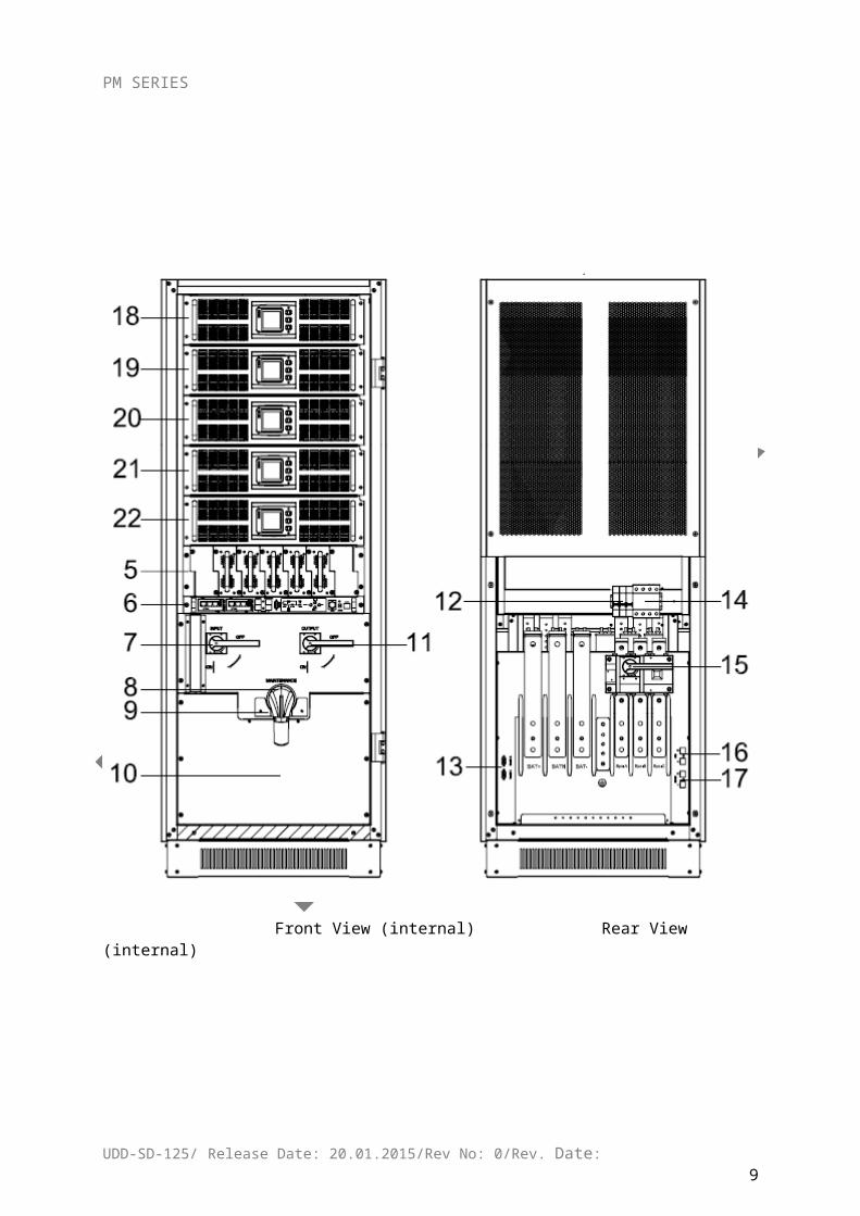
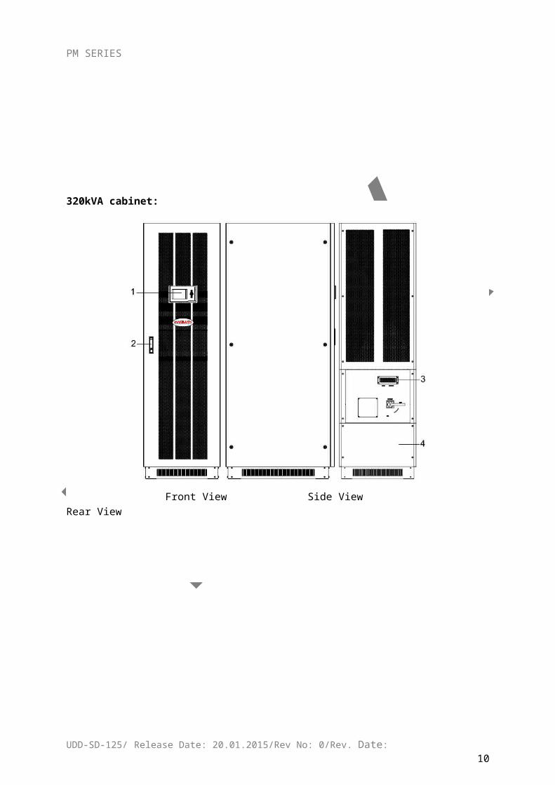
320kVA cabinet:
Front View Side View Rear View
Front View (internal) Rear View (internal)
UDD-SD-125/ Release Date: 20.01.2015/Rev No: 0/Rev. Date:9
PM SERIES
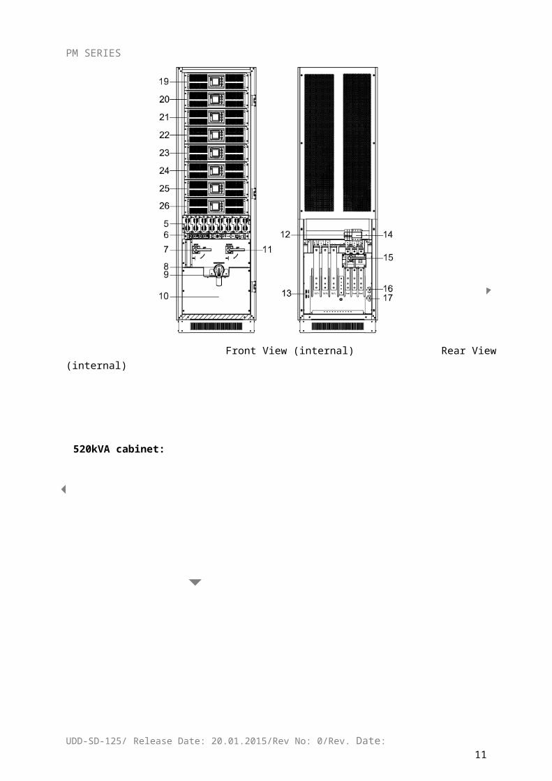
520kVA cabinet:
Front View Side View Rear View
Front View (internal) Rear View (internal)
UDD-SD-125/ Release Date: 20.01.2015/Rev No: 0/Rev. Date:10
PM SERIES
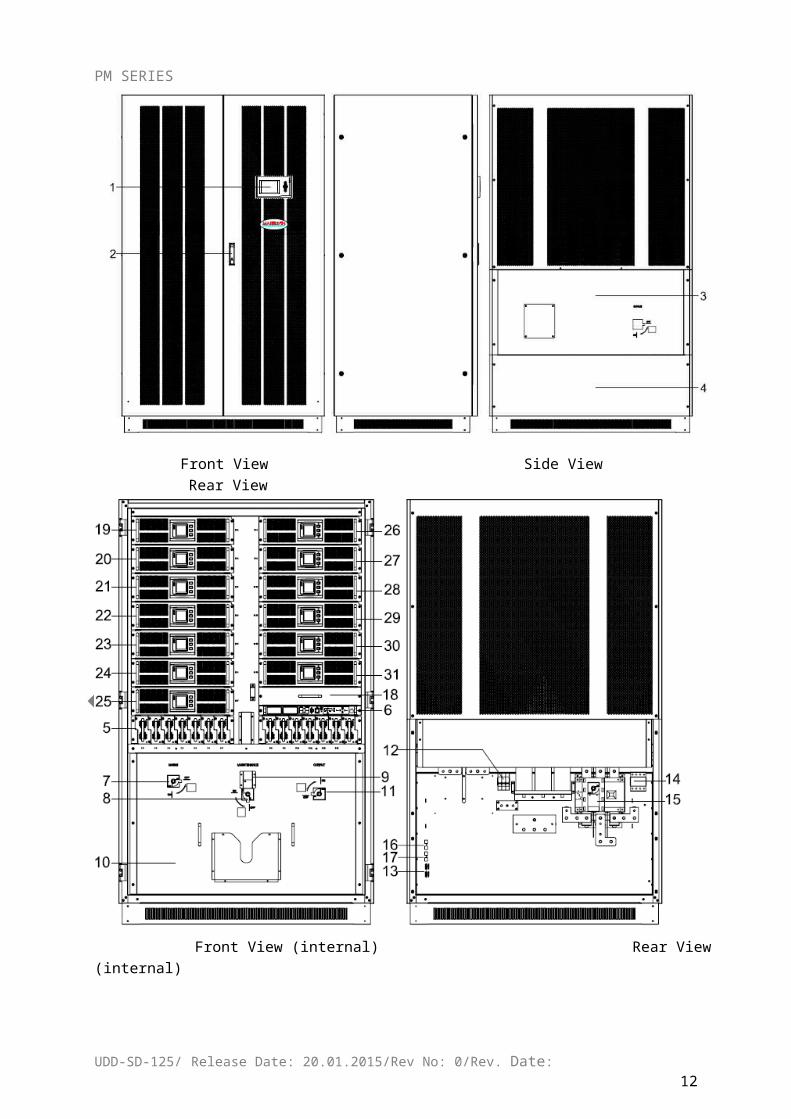
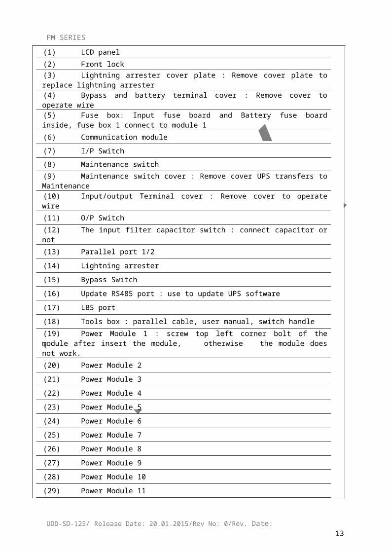
(1) LCD panel
(2) Front lock
(3) Lightning arrester cover plate : Remove cover plate to replace lightning arrester
(4) Bypass and battery terminal cover : Remove cover to operate wire
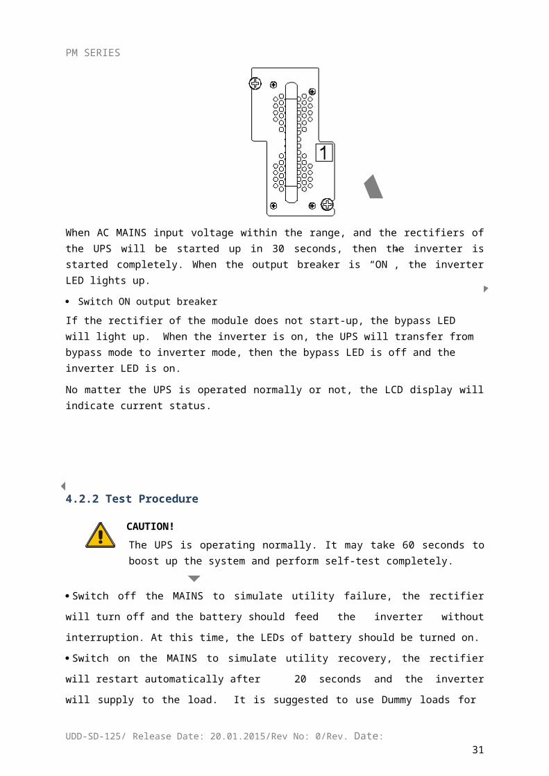
(5) Fuse box: Input fuse board and Battery fuse board inside, fuse box 1 connect to module 1
(6) Communication module
(7) I/P Switch
(8) Maintenance switch
(9) Maintenance switch cover : Remove cover UPS transfers to Maintenance
(10) Input/output Terminal cover : Remove cover to operate wire
(11) O/P Switch
(12) The input filter capacitor switch : connect capacitor or not
(13) Parallel port 1/2
(14) Lightning arrester
(15) Bypass Switch
(16) Update RS485 port : use to update UPS software
(17) LBS port
(18) Tools box : parallel cable, user manual, switch handle
(19) Power Module 1 : screw top left corner bolt of the module after insert the module, otherwise the module does not work.
(20) Power Module 2
(21) Power Module 3
(22) Power Module 4
(23) Power Module 5
(24) Power Module 6
(25) Power Module 7
(26) Power Module 8
(27) Power Module 9
(28) Power Module 10
(29) Power Module 11
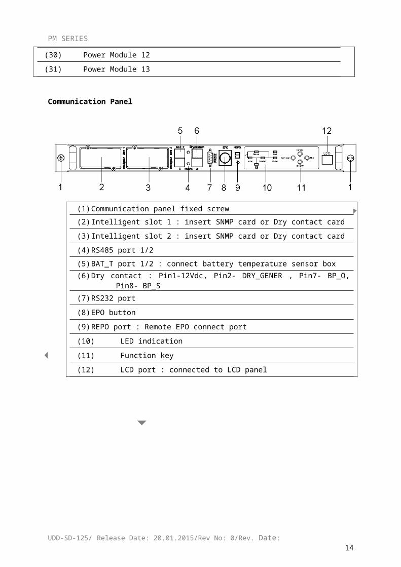
(30) Power Module 12
(31) Power Module 13
Communication Panel
UDD-SD-125/ Release Date: 20.01.2015/Rev No: 0/Rev. Date:11
PM SERIES
(1) Communication panel fixed screw
(2) Intelligent slot 1 : insert SNMP card or Dry contact card
(3) Intelligent slot 2 : insert SNMP card or Dry contact card
(4) RS485 port 1/2
(5) BAT_T port 1/2 : connect battery temperature sensor box
(6) Dry contact : Pin1-12Vdc, Pin2- DRY_GENER , Pin7- BP_O, Pin8- BP_S
(7) RS232 port
(8) EPO button
(9) REPO port : Remote EPO connect port
(10) LED indication
(11) Function key
(12) LCD port : connected to LCD panel
Fuse box
UDD-SD-125/ Release Date: 20.01.2015/Rev No: 0/Rev. Date:12
PM SERIES
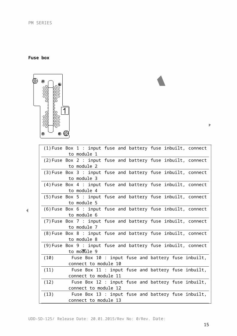
(1) Fuse Box 1 : input fuse and battery fuse inbuilt, connect to module 1
(2) Fuse Box 2 : input fuse and battery fuse inbuilt, connect to module 2
(3) Fuse Box 3 : input fuse and battery fuse inbuilt, connect to module 3
(4) Fuse Box 4 : input fuse and battery fuse inbuilt, connect to module 4
(5) Fuse Box 5 : input fuse and battery fuse inbuilt, connect to module 5
(6) Fuse Box 6 : input fuse and battery fuse inbuilt, connect to module 6
(7) Fuse Box 7 : input fuse and battery fuse inbuilt, connect to module 7
(8) Fuse Box 8 : input fuse and battery fuse inbuilt, connect to module 8
(9) Fuse Box 9 : input fuse and battery fuse inbuilt, connect to module 9
(10) Fuse Box 10 : input fuse and battery fuse inbuilt, connect to module 10
(11) Fuse Box 11 : input fuse and battery fuse inbuilt, connect to module 11
(12) Fuse Box 12 : input fuse and battery fuse inbuilt, connect to module 12
(13) Fuse Box 13 : input fuse and battery fuse inbuilt, connect to module 13
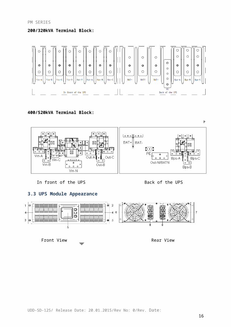
200/320kVA Terminal Block:
400/520kVA Terminal Block:
UDD-SD-125/ Release Date: 20.01.2015/Rev No: 0/Rev. Date:13
PM SERIES
In front of the UPS Back of the UPS
3.3 UPS Module Appearance
Front View Rear View
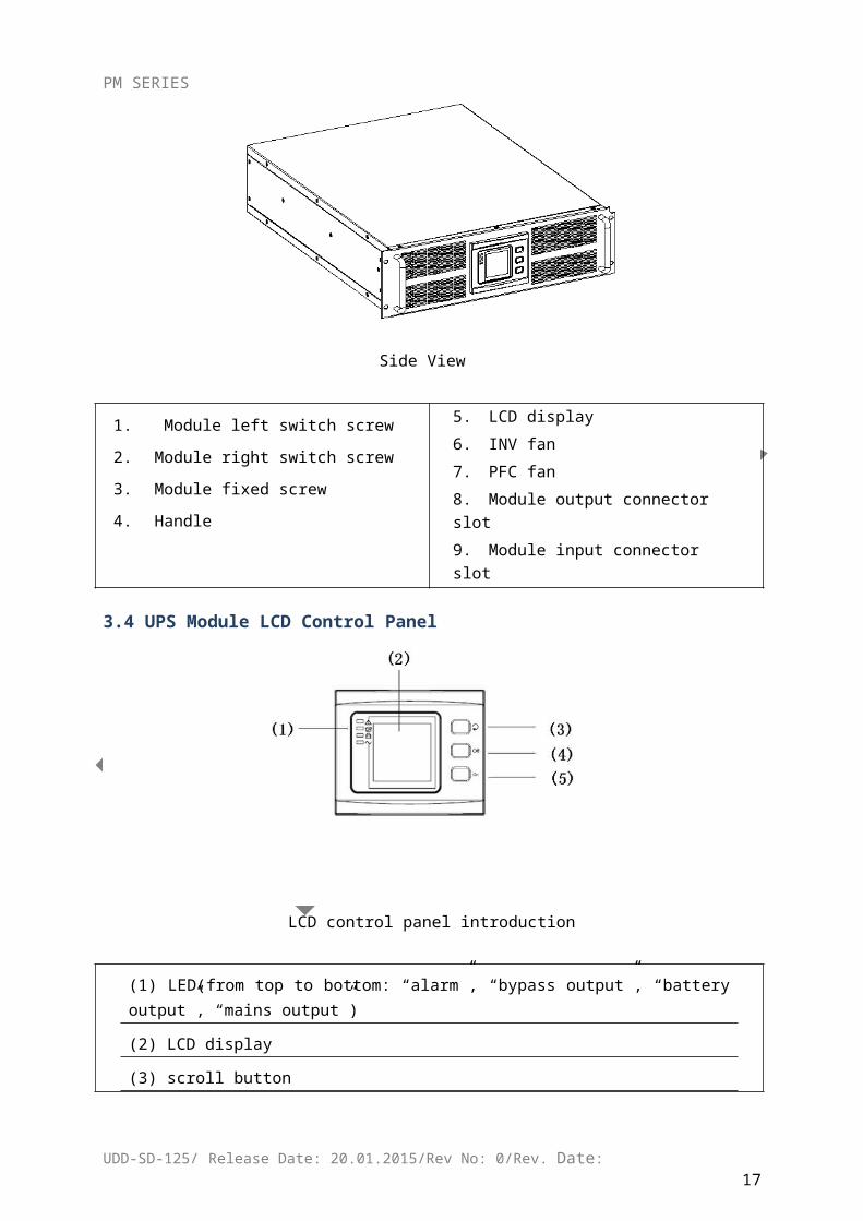
Side View
1. Module left switch screw
2.Module right switch screw
3.Module fixed screw
4.Handle
5. LCD display
6. INV fan
7. PFC fan
8. Module output connector slot
9. Module input connector slot
3.4 UPS Module LCD Control Panel
UDD-SD-125/ Release Date: 20.01.2015/Rev No: 0/Rev. Date:14
PM SERIES
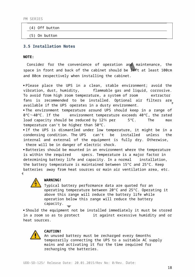
LCD control panel introduction
(1) LED(from top to bottom: “alarm”, “bypass output”, “battery output”, “mains output”)
(2) LCD display
(3) scroll button
(4) Off button
(5) On button
3.5 Installation Notes
NOTE:
Consider for the convenience of operation and maintenance, the space in front and back of the cabinet should be left at least 100cm and 80cm respectively when installing the cabinet.
Please place the UPS in a clean, stable environment; avoid the vibration, dust, humidity, flammable gas and liquid, corrosive. To avoid from high room temperature, a system of room extractor fans is recommended to be installed. Optional air filters are available if the UPS operates in a dusty environment.
The environment temperature around UPS should keep in a range of 0℃ ~ 40℃. If the environment temperature exceeds 40℃, the rated load capacity should be reduced by 12%
per 5℃. The max temperature can't be higher than 50℃. If the UPS is dismantled under low temperature, it might be in a condensing condition. The UPS
can't be installed unless the internal and external of the equipment is fully dry. Otherwise, there will be in danger of electric shock.
Batteries should be mounted in an environment where the temperature is within the required specs. Temperature is a major factor in determining battery life and capacity. In a normal installation, the battery temperature is maintained between 15°C and 25°C. Keep batteries away from heat sources or main air ventilation area, etc.
WARNING!Typical battery performance data are quoted for an operating temperature between 20°C and 25°C. Operating it above this range will reduce the battery life while operation below this range will reduce the battery capacity.
Should the equipment not be installed immediately it must be stored in a room so as to protect it against excessive humidity and or heat sources.
CAUTION!
UDD-SD-125/ Release Date: 20.01.2015/Rev No: 0/Rev. Date:15
PM SERIES
An unused battery must be recharged every 6months temporarily connecting the UPS to a suitable AC supply mains and activating it for the time required for recharging the batteries.
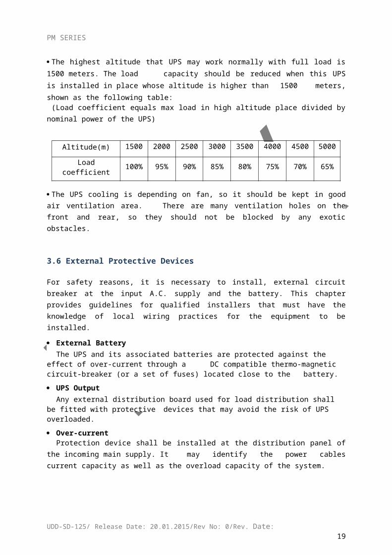
The highest altitude that UPS may work normally with full load is 1500 meters. The load
capacity should be reduced when this UPS is installed in place whose altitude is higher than
1500 meters, shown as the following table: (Load coefficient equals max load in high altitude place divided by nominal power of the UPS)
Altitude(m) 1500 2000 2500 3000 3500 4000 4500 5000
Load coefficient 100% 95% 90% 85% 80% 75% 70% 65%
The UPS cooling is depending on fan, so it should be kept in good air ventilation area. There are many ventilation holes on the front and rear, so they should not be blocked by any exotic obstacles.
3.6 External Protective Devices
For safety reasons, it is necessary to install, external circuit breaker at the input A.C. supply and the battery. This chapter provides guidelines for qualified installers that must have the knowledge of local wiring practices for the equipment to be installed.
External BatteryThe UPS and its associated batteries are protected against the effect of over-current through a DC compatible thermo-magnetic circuit-breaker (or a set of fuses) located close to the battery.
UPS OutputAny external distribution board used for load distribution shall be fitted with protective devices that may avoid the risk of UPS overloaded.
Over-currentProtection device shall be installed at the distribution panel of the incoming main supply. It may identify the power cables current capacity as well as the overload capacity of the system.
3.7 Power Cables
The cable design shall comply with the voltages and currents provided in this section, Kindly
follow local wiring practices and take into consideration the environmental conditions
(temperature and physical support media).
WARNING!UPON STARTING, PLEASE ENSURE THAT YOU ARE AWARE OF THE LOCATION AND OPERATION OF THE EXTERNAL ISOLATORS WHICH ARE CONNECTED TO THE UPS INPUT/BYPASS SUPPLY OF THE MAINS DISTRIBUTION PANEL.CHECK TO SEE IF
UDD-SD-125/ Release Date: 20.01.2015/Rev No: 0/Rev. Date:16
PM SERIES
THESE SUPPLIES ARE ELECTRICALLY ISOLATED, AND POST ANY NECESSARY WARNING SIGNS TO PREVENT ANY INADVERTENT OPERATION
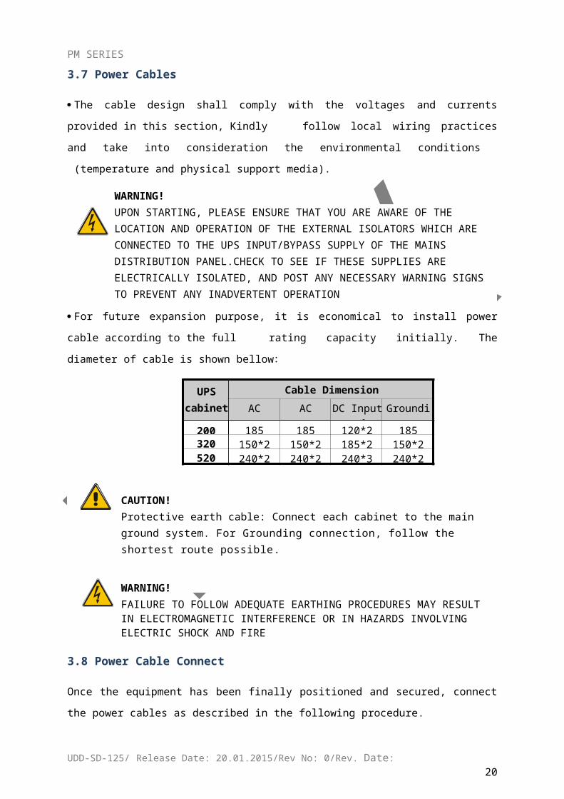
For future expansion purpose, it is economical to install power cable according to the full
rating capacity initially. The diameter of cable is shown bellow:
UPS cabinet
Cable Dimension
AC Input(mm2)
AC Output(mm2)
DC Input(mm2)
Grounding(mm2)
200 185 185 120*2 185320 150*2 150*2 185*2 150*2520 240*2 240*2 240*3 240*2
CAUTION!Protective earth cable: Connect each cabinet to the main ground system. For Grounding connection, follow the shortest route possible.
WARNING!FAILURE TO FOLLOW ADEQUATE EARTHING PROCEDURES MAY RESULT IN ELECTROMAGNETIC INTERFERENCE OR IN HAZARDS INVOLVING ELECTRIC SHOCK AND FIRE
3.8 Power Cable Connect
Once the equipment has been finally positioned and secured, connect the power cables as
described in the following procedure.
Verify the UPS is totally isolated from its external power source and also all power isolators of
the UPS are open. Check to see if they are electrically isolated, and post any necessary warning
signs to prevent their inadvertent operation.
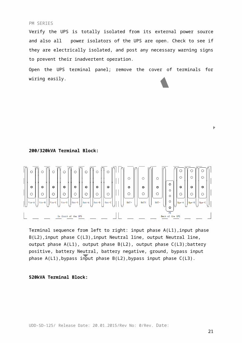
Open the UPS terminal panel; remove the cover of terminals for wiring easily.
200/320kVA Terminal Block:
UDD-SD-125/ Release Date: 20.01.2015/Rev No: 0/Rev. Date:17
PM SERIES
Terminal sequence from left to right: input phase A(L1),input phase B(L2),input phase C(L3),input Neutral line, output Neutral line, output phase A(L1), output phase B(L2), output phase C(L3);battery positive, battery Neutral, battery negative, ground, bypass input phase A(L1),bypass input phase B(L2),bypass input phase C(L3).
520kVA Terminal Block:
In front of the UPS Back of the UPS
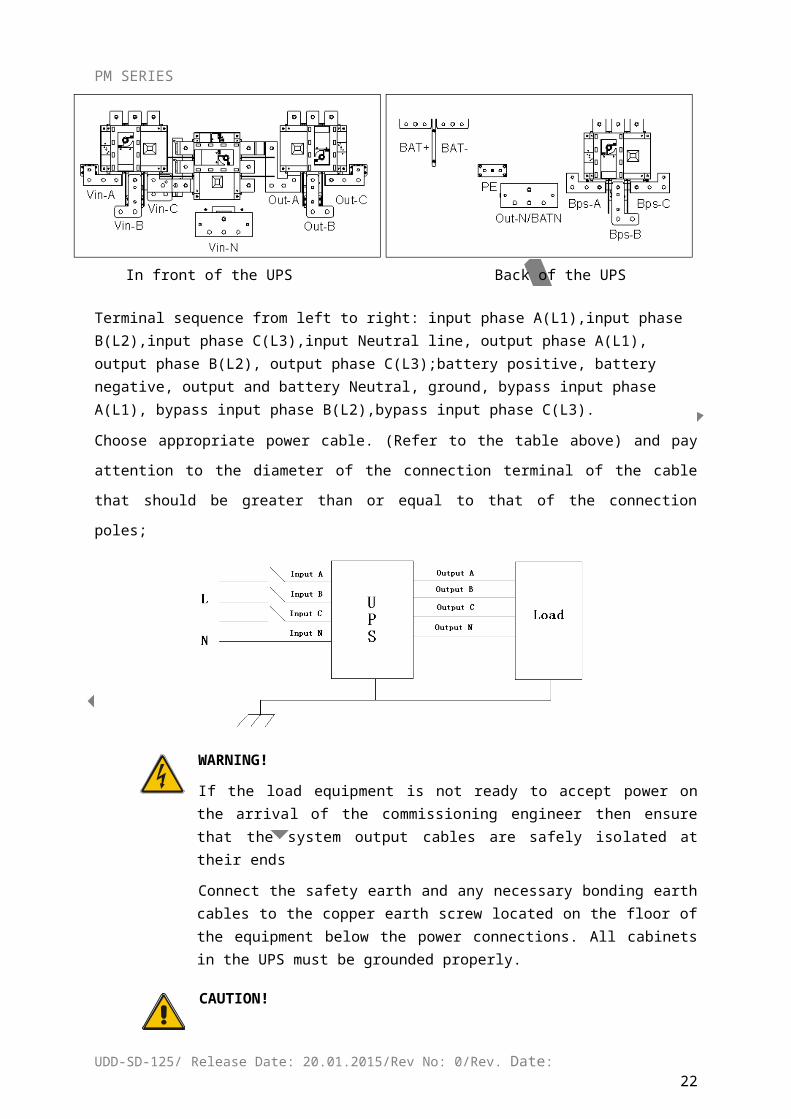
Terminal sequence from left to right: input phase A(L1),input phase B(L2),input phase C(L3),input Neutral line, output phase A(L1), output phase B(L2), output phase C(L3);battery positive, battery negative, output and battery Neutral, ground, bypass input phase A(L1), bypass input phase B(L2),bypass input phase C(L3).
Choose appropriate power cable. (Refer to the table above) and pay attention to the diameter of
the connection terminal of the cable that should be greater than or equal to that of the
connection poles;
UDD-SD-125/ Release Date: 20.01.2015/Rev No: 0/Rev. Date:18
PM SERIES
WARNING!
If the load equipment is not ready to accept power on the arrival of the commissioning engineer then ensure that the system output cables are safely isolated at their ends
Connect the safety earth and any necessary bonding earth cables to the copper earth screw located on the floor of the equipment below the power connections. All cabinets in the UPS must be grounded properly.
CAUTION!The earthing and neutral bonding arrangement must be in accordance with local and national codes of practice.
3.9 Battery Connection
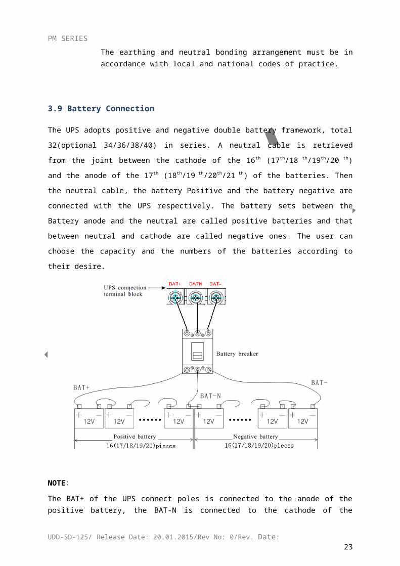
The UPS adopts positive and negative double battery framework, total 32(optional
34/36/38/40) in series. A neutral cable is retrieved from the joint between the cathode of the
16th (17th/18 th/19th/20 th) and the anode of the 17th (18th/19 th/20th/21 th) of the batteries. Then
the neutral cable, the battery Positive and the battery negative are connected with the UPS
respectively. The battery sets between the Battery anode and the neutral are called positive
batteries and that between neutral and cathode are called negative ones. The user can choose
the capacity and the numbers of the batteries according to their desire.
NOTE:
UDD-SD-125/ Release Date: 20.01.2015/Rev No: 0/Rev. Date:19
PM SERIES
The BAT+ of the UPS connect poles is connected to the anode of the positive battery, the BAT-N is connected to the cathode of the positive battery and the anode of the negative battery, the BAT- is connected to the cathode of the negative battery.
Factory setting of the long-run unit is battery quantity---32pcs, battery capacity---12V65AH. When connecting 32/34/38/40 batteries, please re-set desired battery quantity and its capacity after UPS starts at AC mode. Charger current could be adjusted automatically according to battery capacity selected. All related settings can be done through LCD panel or monitoring software.
CAUTION!
Ensure correct polarity battery string series connection. I.e. inter-tier and inter block connections are from (+) to (-) terminals. Don’t mix batteries with different capacity or different brands, or even mix up new and old batteries, either.
WARNING!
Ensure correct polarity of string end connections to the Battery Circuit Breaker and from the Battery Circuit Breaker to the UPS terminals i.e. (+) to (+) / (-) to (-) but disconnect one or more battery cell links in each tier. Do not reconnect these links and do not close the battery circuit breaker unless authorized by the commissioning engineer.
3.10 Online UPS Modules Replacement
For the UPS, modules must be inserted to make a complete UPS system.
The replacement of UPS module is very simple and can be operated online. The control system of the UPS can detect the inserted or removed module(s) automatically. The user may operate easily by following the steps mentioned below.
NOTE:
The UPS module is rather heavy, please move it by two people!
Insert module
UDD-SD-125/ Release Date: 20.01.2015/Rev No: 0/Rev. Date:20
PM SERIES
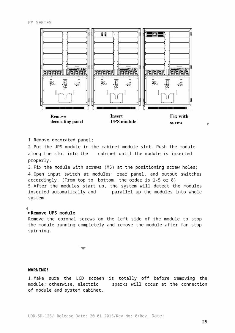
1. Remove decorated panel;2. Put the UPS module in the cabinet module slot. Push the module along the slot into the
cabinet until the module is inserted properly.3. Fix the module with screws (M5) at the positioning screw holes;4. Open input switch at modules’ rear panel, and output switches accordingly. (From top to
bottom, the order is 1-5 or 8)5. After the modules start up, the system will detect the modules inserted automatically and
parallel up the modules into whole system.
Remove UPS moduleRemove the coronal screws on the left side of the module to stop the module running completely and remove the module after fan stop spinning.
WARNING!
1. Make sure the LCD screen is totally off before removing the module; otherwise, electric sparks will occur at the connection of module and system cabinet.
2. The coronal screw at left side of the module controls the operation of the module. Only after the screw is tightened, the module can start running. When insert new module, make sure the screw is tightened properly.
3. When insert the module under battery mode, please press “ON” button at module’s LCD panel until the module starts.
UDD-SD-125/ Release Date: 20.01.2015/Rev No: 0/Rev. Date:21
PM SERIES
3.11 UPS Multi-Module Installation
The basic installation procedure of a parallel system comprising of two or more UPS modules is the same as that of single module system. The following sections introduce the installation procedures specified to the parallel system.
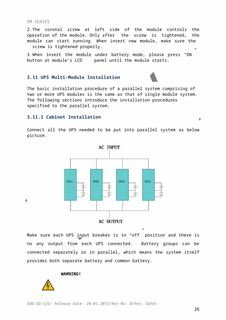
3.11.1 Cabinet Installation
Connect all the UPS needed to be put into parallel system as below picture.
Make sure each UPS input breaker is in “off” position and there is no any output from each UPS
connected. Battery groups can be connected separately or in parallel, which means the system
itself provides both separate battery and common battery.
WARNING!
Make sure the N, A (L1), B (L2), C (L3) lines are correct, and grounding is
well connected.
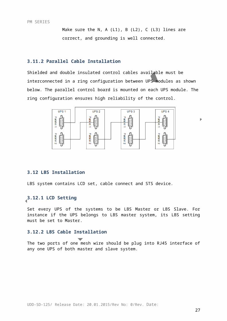
3.11.2 Parallel Cable Installation
Shielded and double insulated control cables available must be interconnected in a ring
configuration between UPS modules as shown below. The parallel control board is mounted on
each UPS module. The ring configuration ensures high reliability of the control.
UDD-SD-125/ Release Date: 20.01.2015/Rev No: 0/Rev. Date:22
PM SERIES
3.12 LBS Installation
LBS system contains LCD set, cable connect and STS device.
3.12.1 LCD Setting
Set every UPS of the systems to be LBS Master or LBS Slave. For instance if the UPS belongs to LBS master system, its LBS setting must be set to Master.
3.12.2 LBS Cable Installation
The two ports of one mesh wire should be plug into RJ45 interface of any one UPS of both master and slave system.
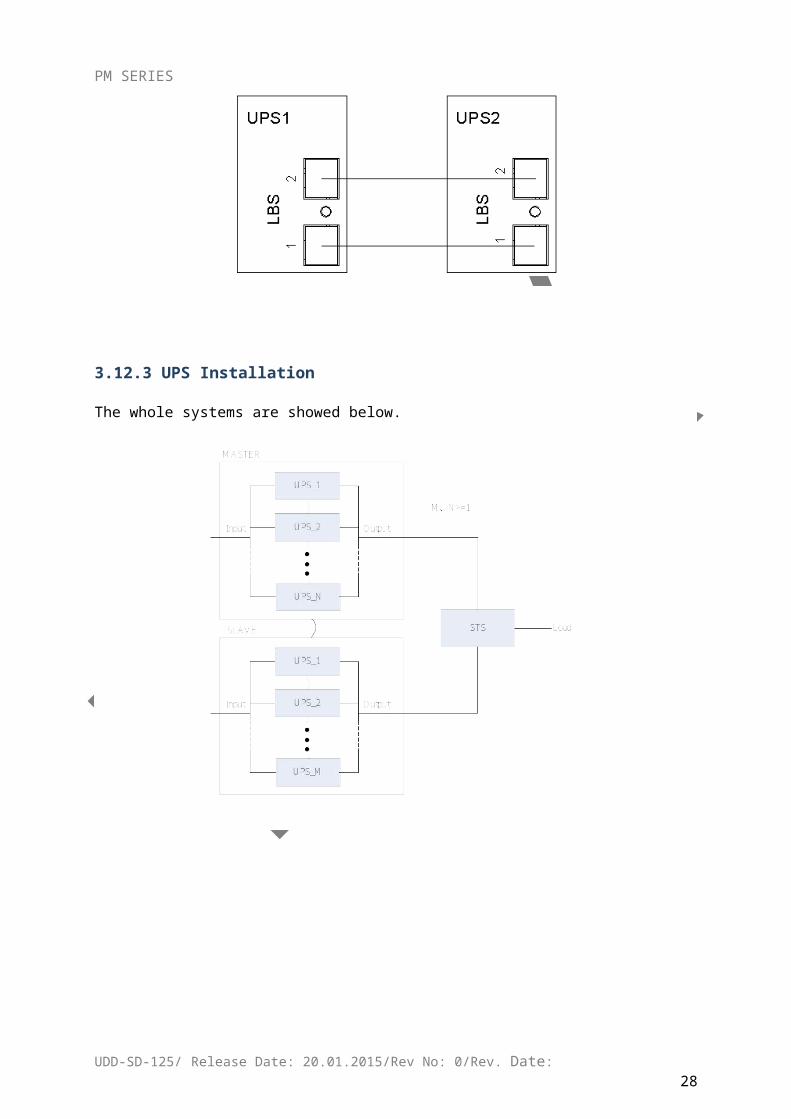
3.12.3 UPS Installation
The whole systems are showed below.
UDD-SD-125/ Release Date: 20.01.2015/Rev No: 0/Rev. Date:23
PM SERIES
4 OPERATION
4.1 Operation Modes
The UPS is a double-conversion on-line UPS that may operate in the following alternative
modes:
Normal modeThe rectifier/charger derives power from the AC Mains and supplies DC power to the inverter while floating and boosting charge the battery simultaneously. Then, the inverter converts the DC power to AC and supplies to the load.
UDD-SD-125/ Release Date: 20.01.2015/Rev No: 0/Rev. Date:24
PM SERIES
Battery mode (Stored Energy Mode)If the AC mains input power fails, the inverter, which obtains power from the battery, supplies the critical AC load. There is no power interruption to the critical load. The UPS will automatically return to Normal Mode when AC recovers.
Bypass modeIf the inverter is out of order, or if overload occurs, the static transfer switch will be activated to transfer the load from the inverter supply to bypass supply without interruption to the critical load. In the event that the inverter output is not synchronized with the bypass AC source, the static switch will perform a transfer of the load from the inverter to the bypass with power interruption to the critical AC load. This is to avoid paralleling of unsynchronized AC sources. This interruption is programmable but typically set to be less than an electrical cycle e.g. less than 15ms (50Hz) or less than 13.33ms (60Hz).
Maintenance mode (Manual Bypass)A manual bypass switch is available to ensure continuity of supply to the critical load when the UPS is out of order or in repair. This manual bypass switch is fitted for all UPS modules and bears for equivalent rated load.
Redundancy modeBased on different demands, The UPS can be set as N+X redundancy mode to increase the reliability to the load connected.
LBS (Load Bus Synchronization)The function of LBS is to keep the output of two independent UPS systems (single unit or multiple units) in synchronization even when the two systems are operating on different modes (bypass/inverter) or on batteries. It is usually used with an STS (Static Transfer Switch) connected to the critical load to achieve Dual Bus configuration.
4.2 Turn on/off UPS
4.2.1 Restart Procedure
CAUTION!
MAKE SURE GROUNDING IS PROPERLY DONE!
Set the Battery Breaker to the “ON” position according to the user’s manual.
Open the front and rear doors of the UPS to access to the main power switches. During this procedure the output terminals will become alive.
CAUTION!
Check to see if the load is safely connected with the output of the UPS. If the load is not ready to receive power from the UPS, make sure that it is safely isolated from the UPS output terminals
UDD-SD-125/ Release Date: 20.01.2015/Rev No: 0/Rev. Date:25
PM SERIES
Turn ON the bypass and input switches of the UPS, make sure that “fuse box” insert the cabinet, and fix with screws
When AC MAINS input voltage within the range, and the rectifiers of the UPS will be started up in 30 seconds, then the inverter is started completely. When the output breaker is “ON”, the inverter LED lights up.
Switch ON output breaker
If the rectifier of the module does not start-up, the bypass LED will light up. When the inverter is on, the UPS will transfer from bypass mode to inverter mode, then the bypass LED is off and the inverter LED is on.
No matter the UPS is operated normally or not, the LCD display will indicate current status.
4.2.2 Test Procedure
CAUTION!
The UPS is operating normally. It may take 60 seconds to boost up the system and perform self-test completely.
Switch off the MAINS to simulate utility failure, the rectifier will turn off and the battery should
feed the inverter without interruption. At this time, the LEDs of battery should be turned on.
Switch on the MAINS to simulate utility recovery, the rectifier will restart automatically after
20 seconds and the inverter will supply to the load. It is suggested to use Dummy loads for
testing. The UPS can be loaded up to its maximum capacity during load test.
UDD-SD-125/ Release Date: 20.01.2015/Rev No: 0/Rev. Date:26
PM SERIES
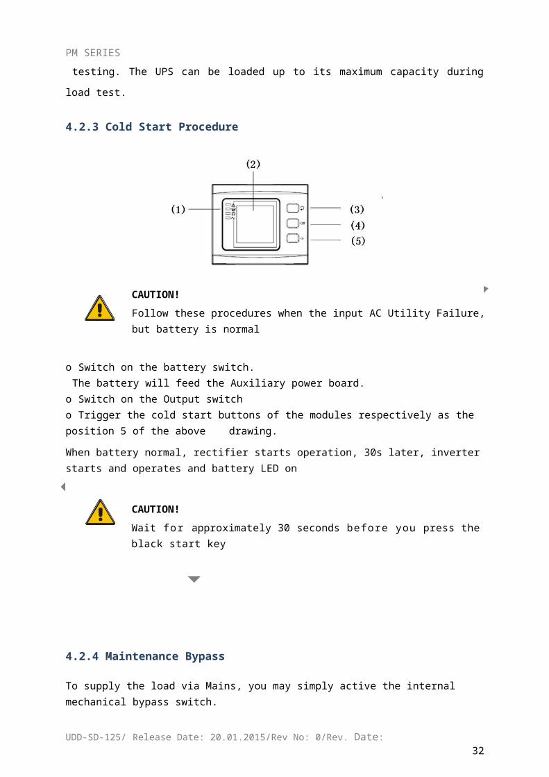
4.2.3 Cold Start Procedure
CAUTION!
Follow these procedures when the input AC Utility Failure, but battery is normal
o Switch on the battery switch.The battery will feed the Auxiliary power board.
o Switch on the Output switcho Trigger the cold start buttons of the modules respectively as the position 5 of the above
drawing.
When battery normal, rectifier starts operation, 30s later, inverter starts and operates and battery LED on
CAUTION!
Wait for approximately 30 seconds before you press the black start key
4.2.4 Maintenance Bypass
To supply the load via Mains, you may simply active the internal mechanical bypass switch.
CAUTION!The load is not protected by the UPS when the internal mechanical bypass system is active and the power is not conditioned.
Switch to mechanical bypass
CAUTION!
UDD-SD-125/ Release Date: 20.01.2015/Rev No: 0/Rev. Date:27
PM SERIES
If the UPS is running normally and can be controlled through the display, carry out steps 1 to 5; otherwise, jump to Step 4.
Open the cover of maintenance switch, the UPS turns to bypass mode automatically.
Switch on MAINTANCE breaker; Switch OFF BATTERY breaker; Switch OFF the MAINS breaker; Switch OFF OUTPUT breaker;
At this time the bypass source will supply to the load through the MAINTENANCE breaker.
Switch to normal operation (from mechanical bypass)
CAUTION!
Never attempt to switch the UPS back to normal operation until you have verified that there are no internal UPS faults
Open the front and rear doors of the UPS to be easily access to the main power switches
Switch ON the output breaker; Switch ON the input breaker; The UPS powers from the static bypass instead of the maintenance bypass, then the bypass
LED will light up. Switch OFF the maintenance bypass breaker, then the output is supplied by the
bypass of the modules. Put on the maintenance switch cover.
The rectifier will operate normally after 30 seconds. If the inverter works normally, the system will be transferred from bypass mode to normal mode.
4.2.5 Shut Down Procedure
CAUTION!
This procedure should be followed to completely shut down the UPS and the LOAD. After all power switches, isolators and circuit breakers are opened, there will be no output.
Press the INVERTER OFF button on the right side of the operator control panel for about two seconds;
The Inverter LED will be extinguished and audible alarm comes simultaneously.
Switch OFF the BATTERY breaker; Open the UPS door to easily access to the main power switch;
UDD-SD-125/ Release Date: 20.01.2015/Rev No: 0/Rev. Date:28
PM SERIES
Switch OFF the input breaker. Switch OFF the OUTPUT switch. The UPS shuts down;
WARNING! Wait for about 5 minutes for the internal D.C. bus bar capacitors to be completely discharged.
4.2.6 Startup Procedure for Parallel System
Connect parallel cable, input/output cable, and battery cable well; modify the parallel board jumpers correctly.
Measure the positive and negative battery pack voltage. Battery breaker is opened temporarily.
Switch ON the output switch at the front door.
According to the startup procedure for single unit, set the operation mode of each UPS: single mode is changed to parallel mode; set the parallel number for each UPS; up to 4 units can be parallel; set the ID of each cabinet, the ID of each unit must be different.
Switch ON the input breaker. Close the external input switch and start from mains.
After start from mains, check the LCD interface of each UPS to see if the ID, VA is the same with the actual values.
Switch ON the external battery breaker of each UPS. Check if the charging current displayed in LCD is normal.
NOTE
The UPS cannot be parallel until each single unit is normal.
4.3 The Display
4.3.1 System LCD Display
UDD-SD-125/ Release Date: 20.01.2015/Rev No: 0/Rev. Date:29
PM SERIES
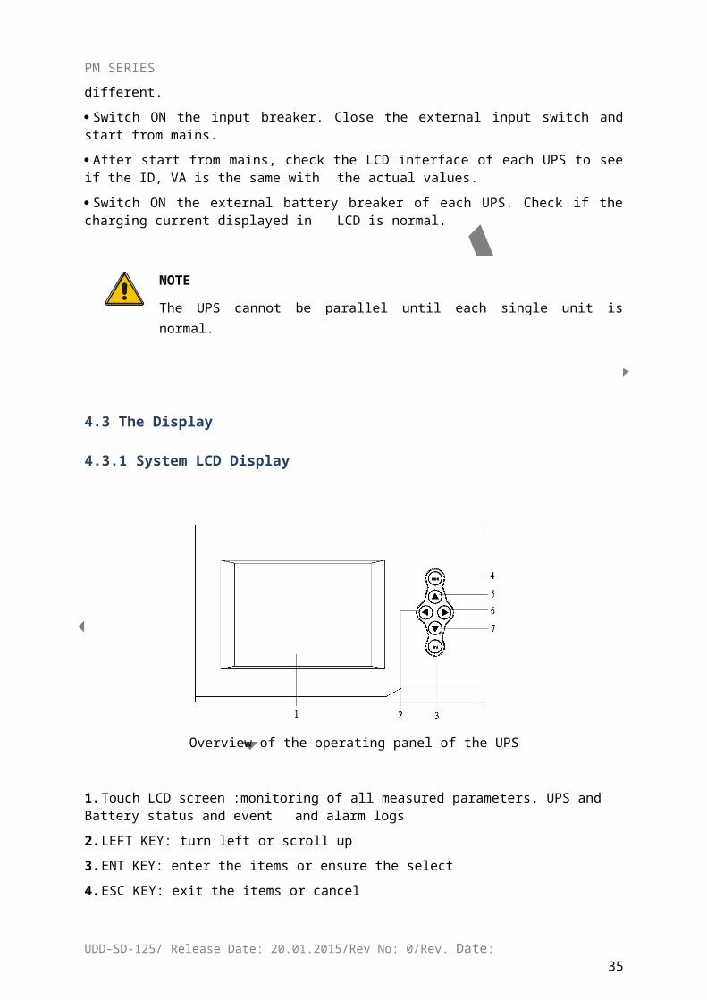
Overview of the operating panel of the UPS
1. Touch LCD screen :monitoring of all measured parameters, UPS and Battery status and event and alarm logs
2. LEFT KEY: turn left or scroll up
3. ENT KEY: enter the items or ensure the select
4. ESC KEY: exit the items or cancel
5. UP KEY: scroll up
6. RIGHT KEY: turn right or scroll down
7. DOWN KEY: scroll down
Introduction
CAUTION!
The display provides more functions than those described in this manual.
UDD-SD-125/ Release Date: 20.01.2015/Rev No: 0/Rev. Date:30
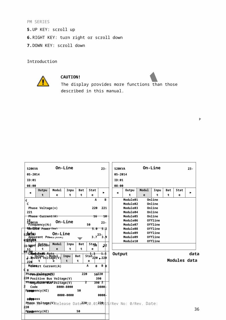
520KVA 23-05-2014ID:01 08:00
◄ Output Module Input Batt State ►
A B CPhase Voltage(v) 220 221 221Phase Current(A) 16 10 18Frequency(HZ) 50Active Power(kw) 5.0 5.2 5.6Apparent Power(KVA) 3.7 3.9 4.1 Load percent(%) 50 52 53Load Peak Rate 1.3 1.5 1.8
520KVA 23-05-2014ID:01 08:00
◄Outpu
t Module Input Batt State ►
Module01 OnlineModule02 OnlineModule03 OnlineModule04 Online Module05 OnlineModule06 OfflineModule07 OfflineModule08 OfflineModule09 OfflineModule09 OfflineModule10 Offline
PM SERIES
Output data Modules data
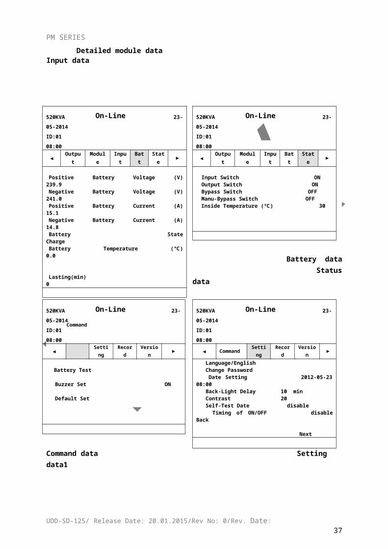
Detailed module data Input data
Battery data Status data
UDD-SD-125/ Release Date: 20.01.2015/Rev No: 0/Rev. Date:31
On-LineOn-Line
520KVA 23-05-2014ID:01 08:00
◄ Output Module Input Batt State ►
Module01 Invert Voltage(V) 220 220 220 Invert Current(A) 0 0 0 Frequency(HZ) 50 Positive Bus Voltage(V) 390 Negative Bus Voltage(V) 390 Code 8000-8000 D800-8000 0000-0000 0000-0000
Back
520KVA 23-05-2014ID:01 08:00
◄Outpu
t Module Input Batt State ►
Mains A B C Phase Voltage(V) 220 220 220 Phase Current(A) 2 2 2 Frequency(HZ) 50
Bypass Phase Voltage(V) 220 220 220 Frequency(HZ) 50
On-LineOn-Line
520KVA 23-05-2014ID:01 08:00
◄ Output Module Input Batt State ►
Positive Battery Voltage (V) 239.9Negative Battery Voltage (V) 241.0Positive Battery Current (A) 15.1Negative Battery Current (A) 14.8Battery State ChargeBattery Temperature (℃) 0.0
Lasting(min) 0
520KVA 23-05-2014ID:01 08:00
◄Outpu
t Module Input Batt State ►
Input Switch ONOutput Switch ONBypass Switch OFFManu-Bypass Switch OFFInside Temperature (℃) 30
PM SERIES
Command data Setting data1
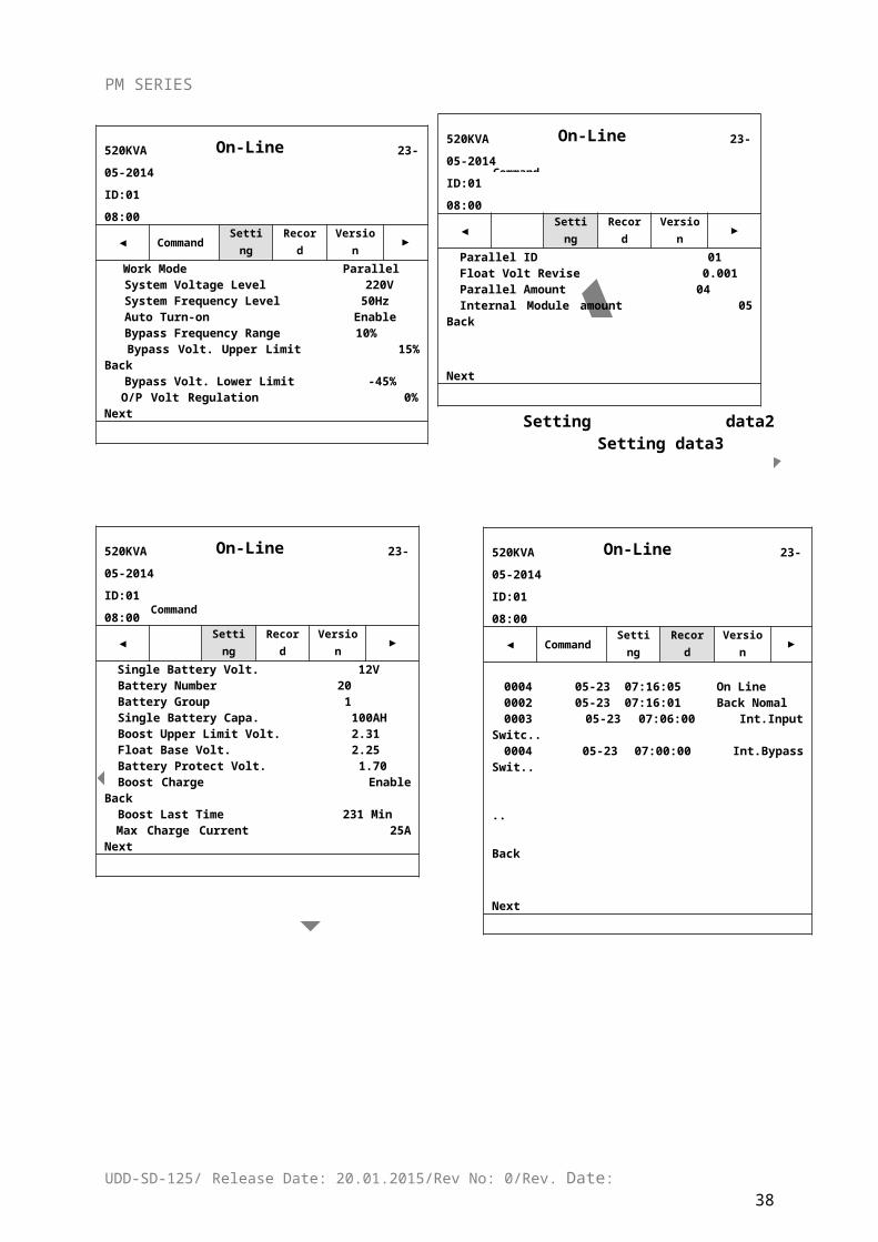
Setting data2 Setting data3
UDD-SD-125/ Release Date: 20.01.2015/Rev No: 0/Rev. Date:32
520KVA 23-05-2014ID:01 08:00
◄ Setting Record Version ►
Battery Test
Buzzer Set ON Default Set
Command
520KVA 23-05-2014ID:01 08:00
◄ Command Setting Record Version ►
Language/English Change Password Date Setting 2012-05-23 08:00 Back-Light Delay 10 min Contrast 20 Self-Test Date disable Timing of ON/OFF disable Back
Next
On-Line
520KVA 23-05-2014ID:01 08:00
◄ Setting Record Version ►
Parallel ID 01Float Volt Revise 0.001Parallel Amount 04Internal Module amount 05 Back
Next
Command
On-Line
520KVA 23-05-2014ID:01 08:00
◄ Command Setting Record Version ►
Work Mode Parallel System Voltage Level 220V System Frequency Level 50Hz Auto Turn-on Enable Bypass Frequency Range 10% Bypass Volt. Upper Limit 15% Back Bypass Volt. Lower Limit -45%
O/P Volt Regulation 0% Next
On-LineOn-Line
520KVA 23-05-2014ID:01 08:00
◄ Setting Record Version ►
Single Battery Volt. 12VBattery Number 20Battery Group 1Single Battery Capa. 100AHBoost Upper Limit Volt. 2.31Float Base Volt. 2.25Battery Protect Volt. 1.70Boost Charge Enable BackBoost Last Time 231 MinMax Charge Current 25A Next
Command
520KVA 23-05-2014ID:01 08:00
◄ Command Setting Record Version ►
0004 05-23 07:16:05 On Line0002 05-23 07:16:01 Back Nomal0003 05-23 07:06:00 Int.Input Switc..0004 05-23 07:00:00 Int.Bypass Swit..
.. Back
Next
PM SERIES
Setting data4 Record data
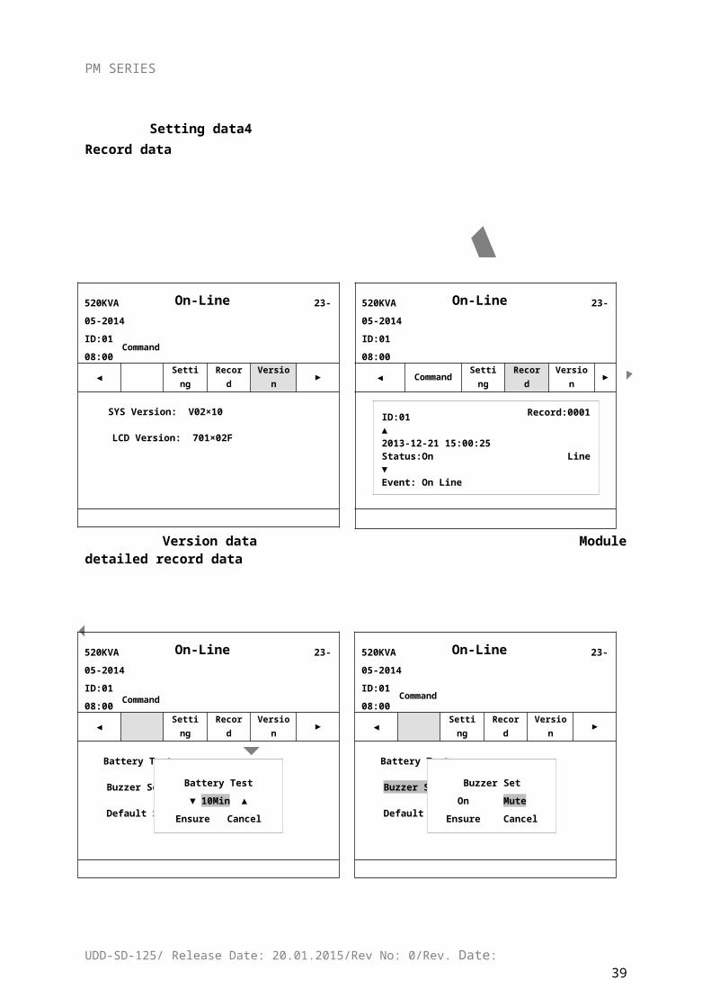
Version data Module detailed record data
Setting of battery test Setting of Buzzer
UDD-SD-125/ Release Date: 20.01.2015/Rev No: 0/Rev. Date:33
On-Line
520KVA 23-05-2014ID:01 08:00
◄Comman
d Setting Record Version ►
ID:01 Record:0001 ▲2013-12-21 15:00:25 Status:On Line ▼Event: On LineAlarm:CODE:CC00-0000 DF00-0000 0000 0000-0000 0000-0000 Quit
On-Line
520KVA 23-05-2014ID:01 08:00
◄ Setting Record Version ►
SYS Version: V02×10
LCD Version: 701×02F
Command
On-Line
520KVA 23-05-2014ID:01 08:00
◄ Setting Record Version ►
Battery Test Battery Test
Buzzer Set
Default Set
Command
Buzzer Set
On MuteEnsure Cancel
On-Line
520KVA 23-05-2014ID:01 08:00
◄ Setting Record Version ►
Battery Test Battery Test
Buzzer Set
Default Set
Command
Battery Test
▼ 10Min ▲Ensure Cancel
PM SERIES
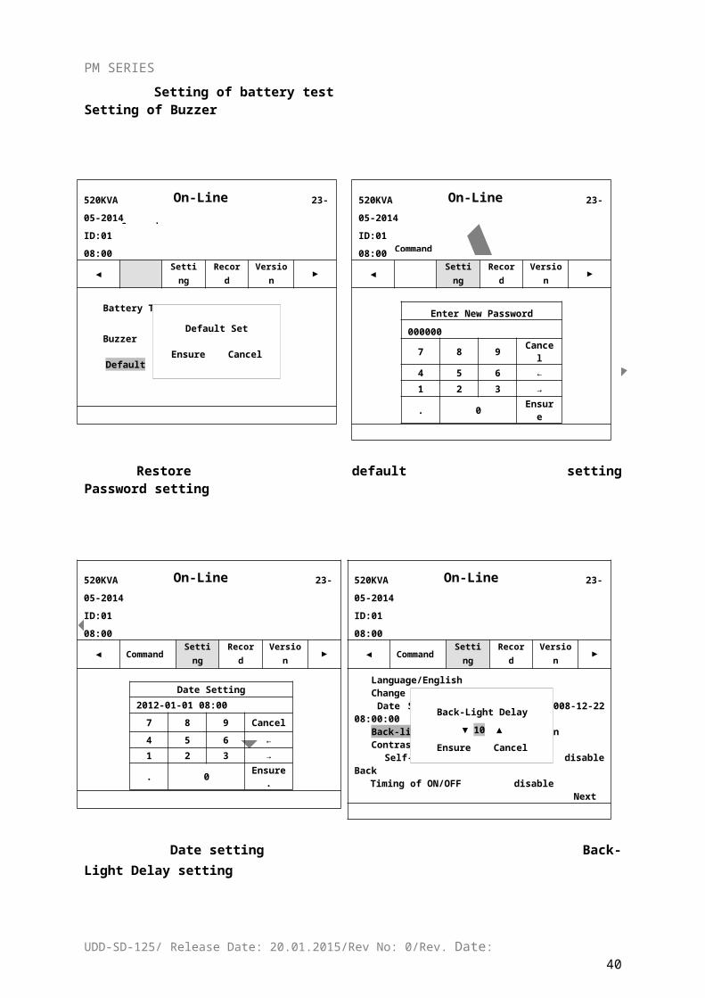
Restore default setting Password setting
Date setting Back-Light Delay setting
UDD-SD-125/ Release Date: 20.01.2015/Rev No: 0/Rev. Date:34
On-Line
520KVA 23-05-2014ID:01 08:00
◄ Setting Record Version ►
Enter New Password
0000007 8 9 Cancel
4 5 6 ←1 2 3 →
. 0 Ensure
On-Line
520KVA 23-05-2014ID:01 08:00
◄ Setting Record Version ►
Battery Test Battery Test
Buzzer Default
Command
Default Set
Ensure Cancel
On-Line
520KVA 23-05-2014ID:01 08:00
◄ Command Setting Record Version ►
Language/English Change Password Change Password Date Setting 2008-12-22 08:00:00 Back-light Delay Contrast 20 Self-Test Date disable Back Timing of ON/OFF
Next
Back-Light Delay
▼ 10 ▲Ensure Cancel
On-Line
520KVA 23-05-2014ID:01 08:00
◄ Command Setting Record Version ►
Date Setting
2012-01-01 08:00
7 8 9 Cancel
4 5 6 ←1 2 3 →
. 0 Ensure.
PM SERIES
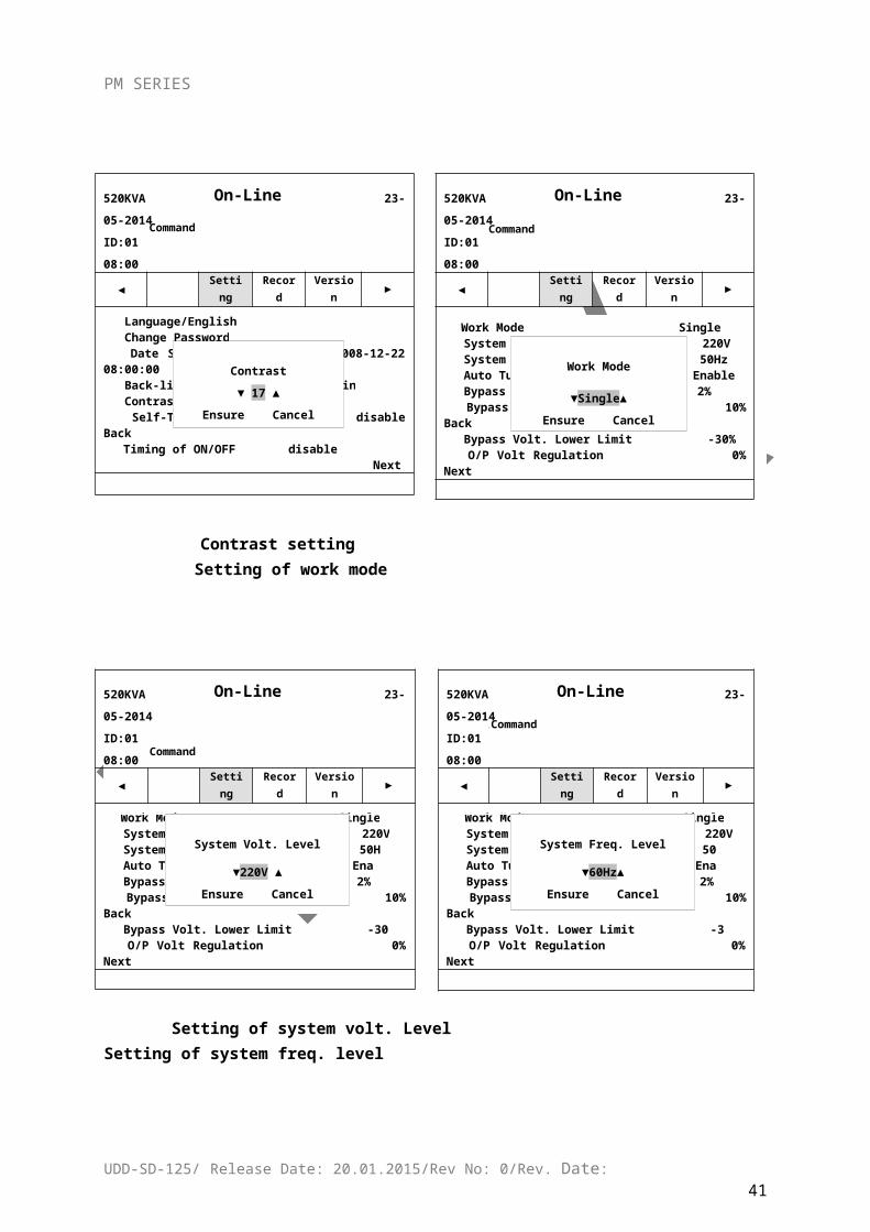
Contrast setting Setting of work mode
Setting of system volt. Level Setting of system freq. level
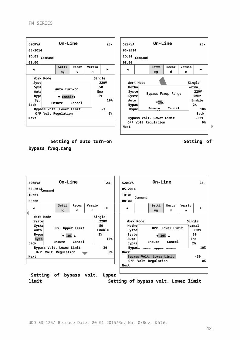
Setting of auto turn-on Setting of bypass freq.rang
UDD-SD-125/ Release Date: 20.01.2015/Rev No: 0/Rev. Date:35
On-Line
520KVA 23-05-2014ID:01 08:00
◄ Setting Record Version ►
Work Mode Single System Voltage Level 220V System Voltage Level 220V System Frequence Level Auto Turn-on Bypass Frequence Range Bypass Volt. Upper Limit 10% Back Bypass Volt. Lower Limit
O/P Volt Regulation 0%
Command
Work Mode
▼Single▲Ensure Cancel
On-Line
520KVA 23-05-2014ID:01 08:00
◄ Setting Record Version ►
Language/English Change Password Change Password Date Setting 2008-12-22 08:00:00 Back-light Delay 10Min Contrast 20 Self-Test Date disable Back Timing of ON/OFF
Next
Contrast
▼ 17 ▲Ensure Cancel
Command
On-Line
520KVA 23-05-2014ID:01 08:00
◄ Setting Record Version ►
Work Mode Single Work Mode Single System Voltage Level 220V System Frequence Level Auto Turn-on Bypass Frequence Range Bypass Volt. Upper Limit 10% Back Bypass Volt. Lower Limit O/P Volt Regulation 0%Regulation 0% Next
System Freq. Level
▼60Hz▲Ensure Cancel
3 Command
On-Line
520KVA 23-05-2014ID:01 08:00
◄ Setting Record Version ►
Work Mode SingleWork Mode Single System Voltage Level 220V System Frequence Level Auto Turn-on Bypass Frequence Range Bypass Volt. Upper Limit 10% Back Bypass Volt. Upper Limit 10% Back Bypass Volt. Lower Limit
O/P Volt Regulation 0%Regulation 0% Next
Command
System Volt. Level
▼220V ▲Ensure Cancel
On-Line
520KVA 23-05-2014ID:01 08:00
◄ Setting Record Version ►
Work Mode Single Method Normal Method Normal System Voltage Level 220V System Frequence Level Auto Turn-on Bypass Frequence Range Bypass Volt. Upper Limit 10% Back Bypass Volt. Lower Limit Bypass Volt. Lower Limit -30%
O/P Volt Regulation 0% Next
Bypass Freq. Range
▼2%▲Ensure Cancel
Command
On-Line
520KVA 23-05-2014ID:01 08:00
◄ Setting Record Version ►
Work Mode SingleSystem Voltage Level 220VSystem Voltage Level 220V
System Frequence Level Auto Turn-on Bypass Frequence Range Bypass Volt. Upper Limit 10% Back Bypass Volt. Lower Limit
O/P Vol Next
Command
Auto Turn-on
▼ Enable▲Ensure Cancel
PM SERIES
Setting of bypass volt. Upper limit Setting of bypass volt. Lower limit
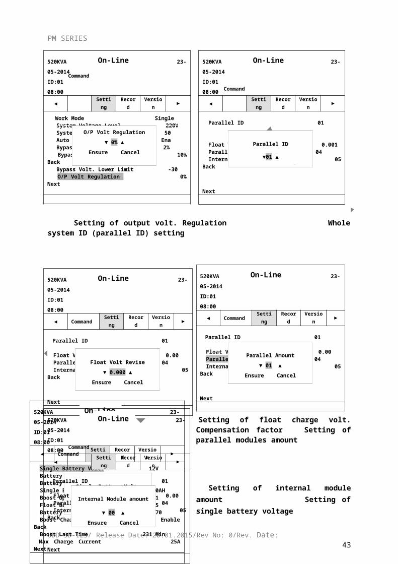
Setting of output volt. Regulation Whole system ID (parallel ID) setting
UDD-SD-125/ Release Date: 20.01.2015/Rev No: 0/Rev. Date:36
On-Line
520KVA 23-05-2014ID:01 08:00
◄ Setting Record Version ►
Work Mode Single Method Normal Method Normal System Voltage Level 220V System Frequence Level Auto Turn-on Bypass Frequence Range Bypass Volt. Upper Limit 10% Back Bypass Volt. Lower Limit Bypass Volt. Lower Limit -30 O/P Volt Regulation 0% Next
BPV. Lower Limit
▼-30% ▲Ensure Cancel
Command
On-Line
520KVA 23-05-2014ID:01 08:00
◄ Setting Record Version ►
Work Mode SingleSystem Voltage Level 220VSystem Voltage Level 220V
System Frequence Level Auto Turn-on Bypass Frequence Range Bypass Volt. Upper Limit 10% Back Bypass Volt. Lower Limit
O/P Volt
BPV. Upper Limit
▼ 10% ▲Ensure Cancel
Command
On-Line
520KVA 23-05-2014ID:01 08:00
◄ Setting Record Version ►
Parallel ID 01
Float Volt Revise Parallel Amount Internal Module amount 05 BackInternal Module amount 05 Back
Next
Parallel ID
▼01 ▲Ensure Cancel
Command
On-Line
520KVA 23-05-2014ID:01 08:00
◄ Setting Record Version ►
Work Mode Single System Voltage Level 220V System Voltage Level 220V System Frequence Level Auto Turn-on Bypass Frequence Range Bypass Volt. Upper Limit 10% Back Bypass Volt. Lower Limit O/P Volt Regulation
Command
O/P Volt Regulation
▼ 0% ▲Ensure Cancel
On-Line
520KVA 23-05-2014ID:01 08:00
◄ Command Setting Record Version ►
Parallel ID 01
Float Volt Revise Parallel AmountInternal Module amount 05 BackInternal Module amount 05 Back
Parallel Amount
▼ 01 ▲Ensure Cancel
PM SERIES
Setting of float charge volt. Compensation factor Setting of parallel modules amount
Setting of internal module amount Setting of single battery voltage
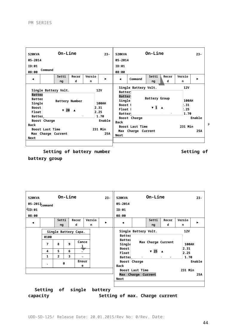
Setting of battery number Setting of battery group
UDD-SD-125/ Release Date: 20.01.2015/Rev No: 0/Rev. Date:37
On-Line
520KVA 23-05-2014ID:01 08:00
◄ Command Setting Record Version ►
Parallel ID 01
Float Volt Revise Parallel Amount Internal Module amount 05 BackInternal Module amount 05 Back
Float Volt Revise
▼ 0.000 ▲Ensure Cancel
520KVA 23-05-2014ID:01 08:00
◄ Command Setting Record Version ►
Single Battery Volt. 12VBattery Number 20Battery Number 20Battery Group 1Single Battery Capa. 100AHBoost Upper Limit Volt. 2.31Float Base Volt. 2.25Battery Protect Volt. 1.70Boost Charge Enable BackBoost Charge Enable BackBoost Last Time 231 MinMax Charge Current 25A Next
Single Battery Volt.
▼ 12V ▲Ensure Cancel
520KVA 23-05-2014ID:01 08:00
◄ Setting Record Version ►
Parallel ID 01
Float Volt Revise Parallel Amount Internal Module amount 05 BackInternal Module amount 05 Back
Next
Internal Module amount
▼ 00 ▲Ensure Cancel
Command
On-Line
520KVA 23-05-2014ID:01 08:00
◄ Command Setting Record Version ►
Single Battery Volt. 12VBattery Number 20Battery Number 20Battery Group 1Single Battery Capa. 100AHBoost Upper Limit Volt. 2.31Float Base Volt. 2.25Battery Protect Volt. 1.70Boost Charge Enable BackBoost Charge Enable BackBoost Last Time 231 MinMax Charge Current 25A Next
Battery Group
▼ 1 ▲
Ensure Cancel
On-Line
520KVA 23-05-2014ID:01 08:00
◄ Setting Record Version ►
Single Battery Volt. 12V
Battery NumberBattery Number 20Battery Group 1Single Battery Capa. 100AHBoost Upper Limit Volt. 2.31Float Base Volt. 2.25Battery Protect Volt. 1.70Boost Charge Enable Boost Charge Enable BackBoost Last Time 231 MinMax Charge Current 25A Next
Command
Battery Number
▼ 20 ▲
Ensure Cancel
520KVA 23-05-2014ID:01 08:00
◄ Setting Record Version ►
Single Battery Volt. 12VBattery Number 20Battery Number 20Battery Group 1Single Battery Capa. 100AHBoost Upper Limit Volt. 2.31Float Base Volt. 2.25Battery Protect Volt. 1.70Boost Charge Enable BackBoost Charge Enable BackBoost Last Time 231 MinMax Charge Current 25A Next
Max Charge Current
▼ 25 ▲
Ensure Cancel
520KVA 23-05-2013ID:01 08:00
◄ Setting Record Version ►
Single Battery Capa.0100
7 8 9 Cancel
4 5 6 ←1 2 3 →
. 0 Ensure
Command
PM SERIES
Setting of single battery capacity Setting of max. Charge current
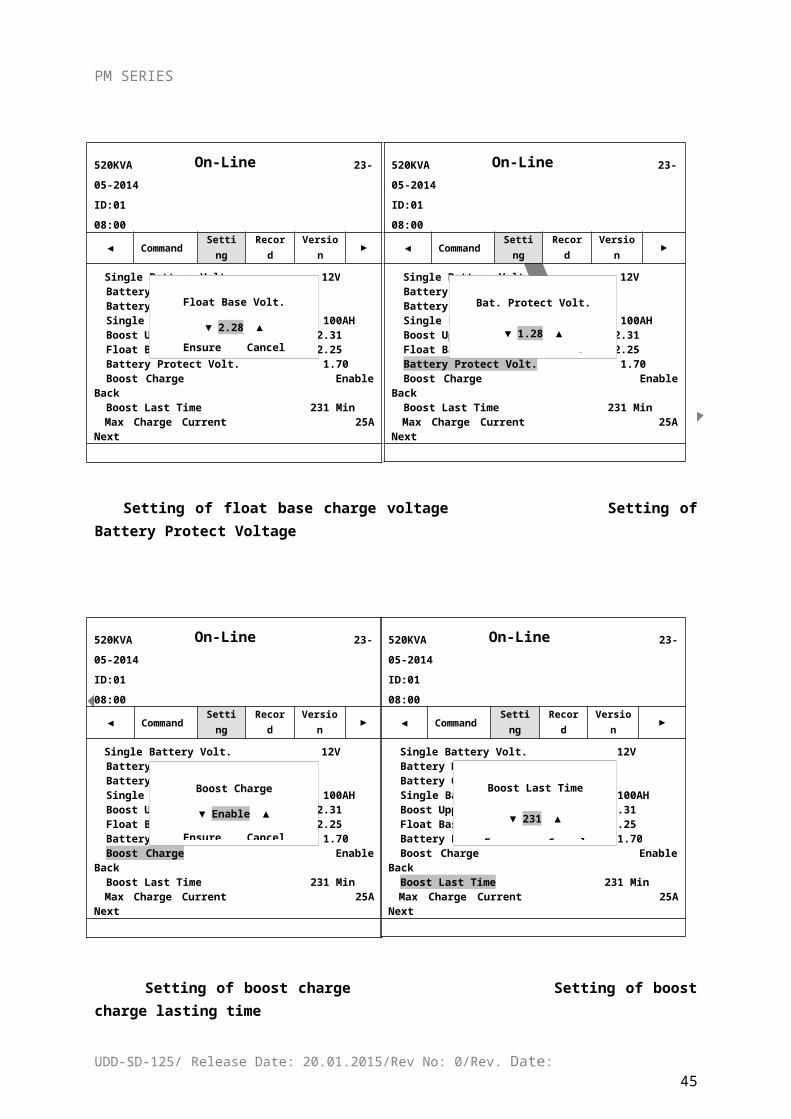
Setting of float base charge voltage Setting of Battery Protect Voltage
Setting of boost charge Setting of boost charge lasting time
UDD-SD-125/ Release Date: 20.01.2015/Rev No: 0/Rev. Date:38
On-Line
520KVA 23-05-2014ID:01 08:00
◄ Command
Setting Record Version ►
Single Battery Volt. 12V Single Battery Volt. 12VBattery Number 20Battery Group 1Single Battery Capa. 100AHBoost Upper Limit Volt. 2.31Float Base Volt. 2.25Battery Protect Volt.Boost Charge Enable BackBoost Charge Enable BackBoost Last Time 231 MinMax Charge Current 25A Next
Bat. Protect Volt.
▼ 1.28 ▲
Ensure Cancel
On-Line
520KVA 23-05-2014ID:01 08:00
◄ Command Setting Record Version ►
Single Battery Volt. 12VSingle Battery Volt. 12VBattery Number 20Battery Group 1Single Battery Capa. 100AHBoost Upper Limit Volt. 2.31Float Base Volt. 2.25Battery Protect Volt. 1.70Boost Charge Enable BackBoost Charge Enable BackBoost Last Time 231 MinMax Charge Current 25A Next
Float Base Volt.
▼ 2.28 ▲Ensure Cancel
On-Line
520KVA 23-05-2014ID:01 08:00
◄ Command Setting Record Version ►
Single Battery Volt. 12VBattery Number 20Battery Number 20Battery Group 1Single Battery Capa. 100AHBoost Upper Limit Volt. 2.31Float Base Volt. 2.25Battery Protect Volt. 1.70Boost Charge Enable BackBoost Last TimeBoost Last Time 231 MinMax Charge Current 25A Next
Boost Last Time
▼ 231 ▲
Ensure Cancel
On-Line
520KVA 23-05-2014ID:01 08:00
◄ Command
Setting Record Version ►
Single Battery Volt. 12VBattery Number 20Battery Number 20Battery Group 1Single Battery Capa. 100AHBoost Upper Limit Volt. 2.31Float Base Volt. 2.25Battery Protect Volt. 1.70Boost ChargeBoost Last Time 231 MinBoost Last Time 231 MinMax Charge Current 25A Next
Boost Charge
▼ Enable ▲
Ensure Cancel
On-Line
520KVA 23-05-2014ID:01 08:00
◄ Command Setting Record Version ►
Single Battery Volt. 12VBattery Number 20Battery Number 20
Battery Group 1Single Battery Capa. 100AHBoost Upper Limit Volt. 2.31Float Base Volt. 2.25Battery Protect Volt. 1.70Boost ChargeBoost Last Time 231 MinBoost Last Time 231 MinMax Charge Current 25A Next
Boost Upper Limit Volt.
▼ 2.32 ▲
Ensure Cancel
PM SERIES
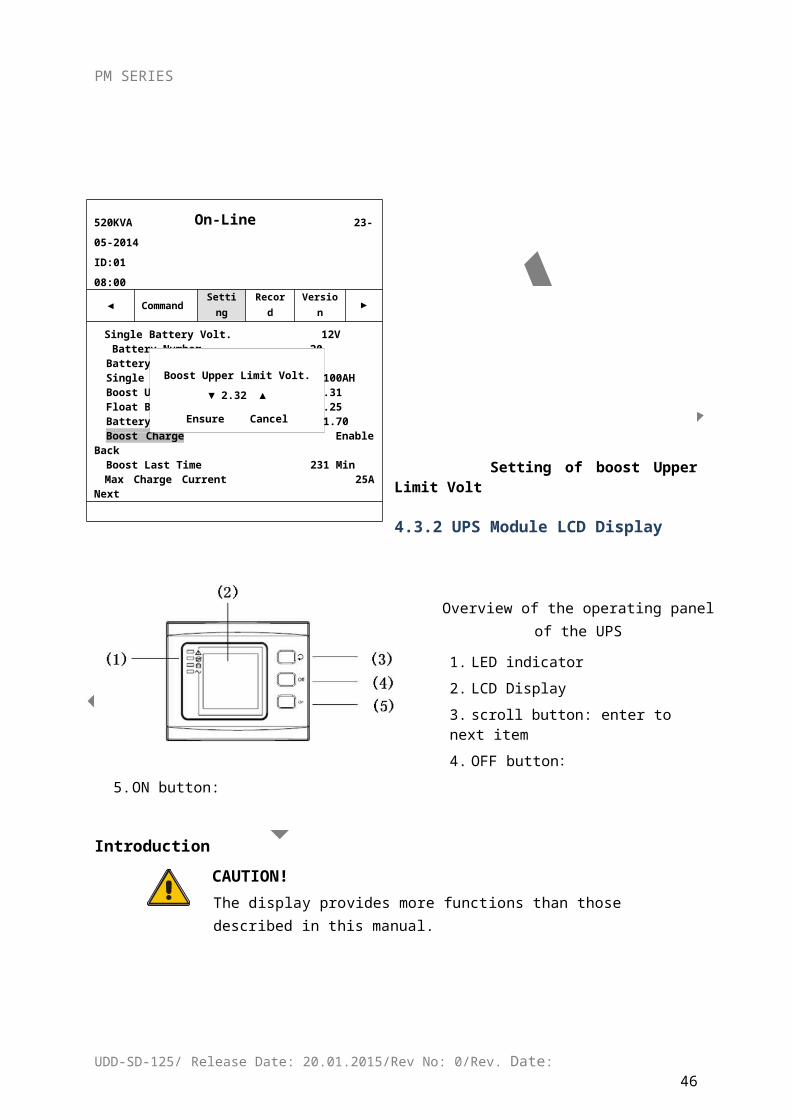
Setting of boost Upper Limit Volt
4.3.2 UPS Module LCD Display
Overview of the operating panel of the UPS
1. LED indicator
2. LCD Display
3. scroll button: enter to next item
4. OFF button:
5. ON button:
Introduction
CAUTION!The display provides more functions than those described in this manual.
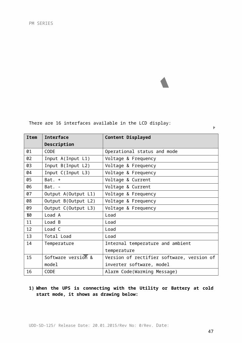
There are 16 interfaces available in the LCD display:
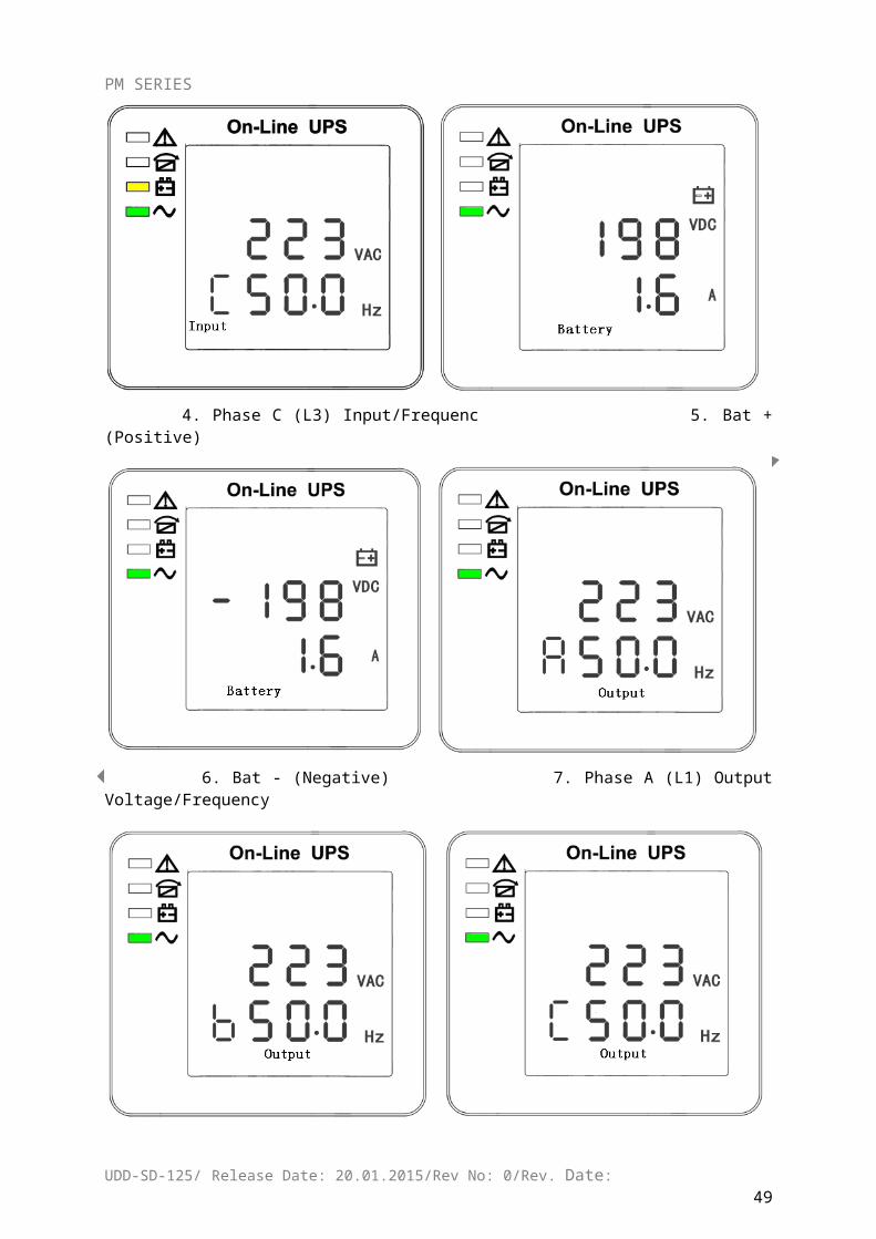
Item Interface Description Content Displayed01 CODE Operational status and mode02 Input A(Input L1) Voltage & Frequency03 Input B(Input L2) Voltage & Frequency04 Input C(Input L3) Voltage & Frequency
UDD-SD-125/ Release Date: 20.01.2015/Rev No: 0/Rev. Date:39
PM SERIES
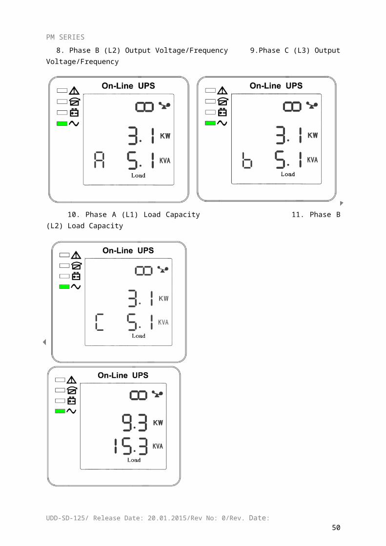
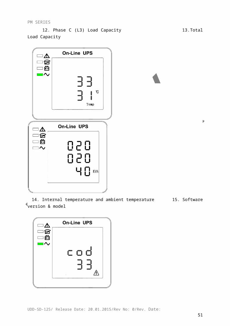
05 Bat. + Voltage & Current06 Bat. - Voltage & Current07 Output A(Output L1) Voltage & Frequency08 Output B(Output L2) Voltage & Frequency09 Output C(Output L3) Voltage & Frequency10 Load A Load11 Load B Load12 Load C Load13 Total Load Load14 Temperature Internal temperature and ambient temperature15
Software version & modelVersion of rectifier software, version of inverter software, model
16 CODE Alarm Code(Warming Message)
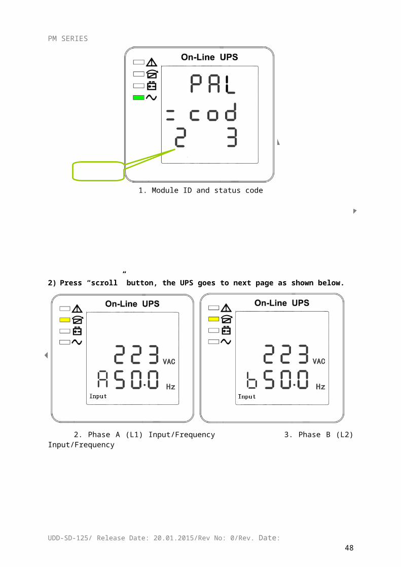
1) When the UPS is connecting with the Utility or Battery at cold start mode, it shows as drawing below:
1. Module ID and status code
2) Press “scroll” button, the UPS goes to next page as shown below.
UDD-SD-125/ Release Date: 20.01.2015/Rev No: 0/Rev. Date:40
Module ID
PM SERIES
2. Phase A (L1) Input/Frequency 3. Phase B (L2) Input/Frequency
4. Phase C (L3) Input/Frequenc 5. Bat + (Positive)
6. Bat - (Negative) 7. Phase A (L1) Output Voltage/Frequency
UDD-SD-125/ Release Date: 20.01.2015/Rev No: 0/Rev. Date:41
PM SERIES
8. Phase B (L2) Output Voltage/Frequency 9.Phase C (L3) Output Voltage/Frequency
10. Phase A (L1) Load Capacity 11. Phase B (L2) Load Capacity
12. Phase C (L3) Load Capacity 13.Total Load Capacity
UDD-SD-125/ Release Date: 20.01.2015/Rev No: 0/Rev. Date:42
PM SERIES
14. Internal temperature and ambient temperature 15. Software version & model
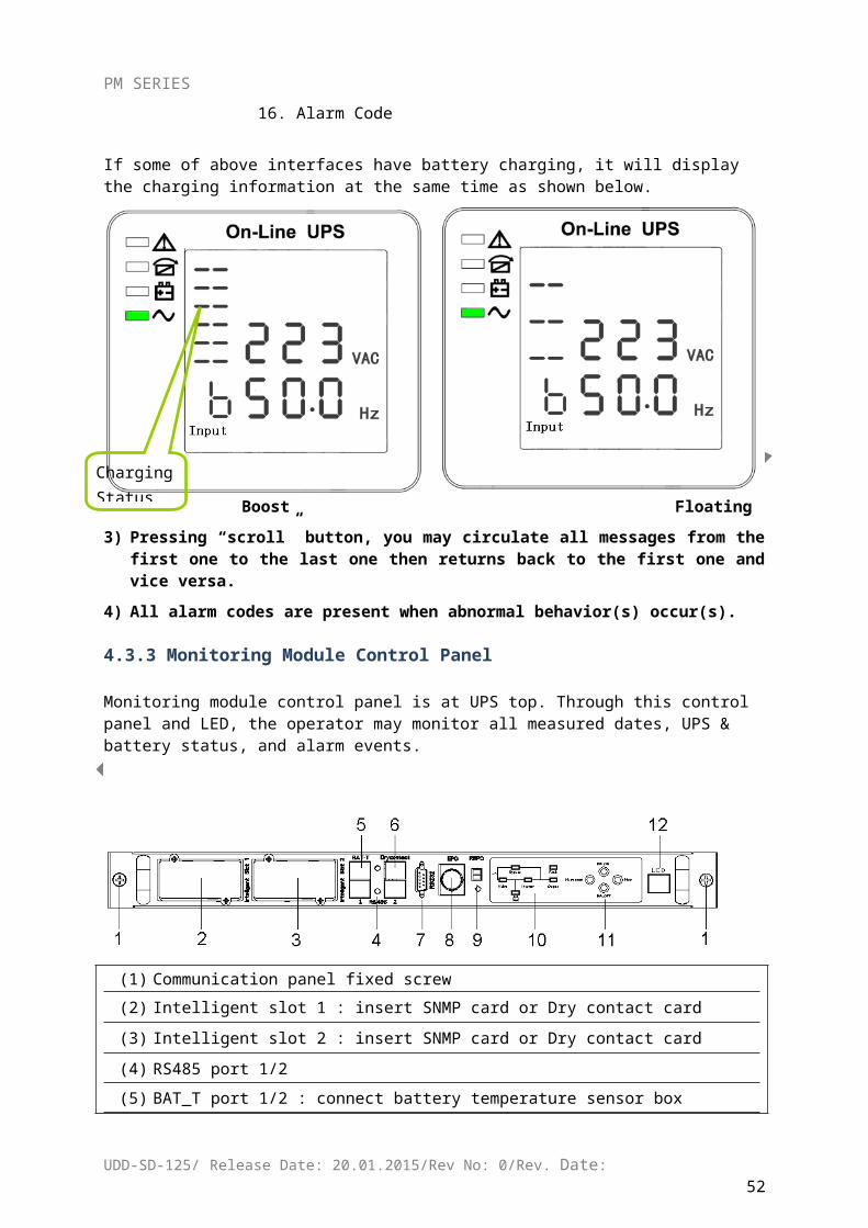
16. Alarm Code
If some of above interfaces have battery charging, it will display the charging information at the same time as shown below.
Boost Floating
UDD-SD-125/ Release Date: 20.01.2015/Rev No: 0/Rev. Date:43
Charging Status
PM SERIES
3) Pressing “scroll” button, you may circulate all messages from the first one to the last one then returns back to the first one and vice versa.
4) All alarm codes are present when abnormal behavior(s) occur(s).
4.3.3 Monitoring Module Control Panel
Monitoring module control panel is at UPS top. Through this control panel and LED, the operator may monitor all measured dates, UPS & battery status, and alarm events.
(1) Communication panel fixed screw
(2) Intelligent slot 1 : insert SNMP card or Dry contact card
(3) Intelligent slot 2 : insert SNMP card or Dry contact card
(4) RS485 port 1/2
(5) BAT_T port 1/2 : connect battery temperature sensor box
(6) Dry contact : Pin1-12Vdc, Pin2- DRY_GENER , Pin7- BP_O, Pin8- BP_S
(7) RS232 port
(8) EPO button
(9) REPO port : Remote EPO connect port
(10) LED indication
(11) Function key
(12) LCD port : connected to LCD panel
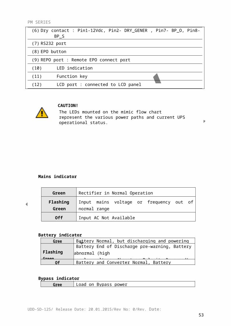
CAUTION!The LEDs mounted on the mimic flow chart represent the various power paths and current UPS operational status.
UDD-SD-125/ Release Date: 20.01.2015/Rev No: 0/Rev. Date:44
PM SERIES
Mains indicator
Green Rectifier in Normal Operation
Flashing Green Input mains voltage or frequency out of normal range
Off Input AC Not Available
Battery indicatorGreen Battery Normal, but discharging and powering the load
Flashing GreenBattery End of Discharge pre-warning, Battery abnormal (highor low voltage, Absent or Polarity Reversed), chargerabnormal
Off Battery and Converter Normal, Battery charging.
Bypass indicatorGreen Load on Bypass power
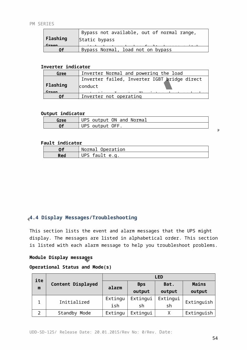
Flashing GreenBypass not available, out of normal range, Static bypassswitch short or broken fault, bypass switch wiring fault, bypassover current
Off Bypass Normal, load not on bypass
Inverter indicatorGreen Inverter Normal and powering the load
Flashing GreenInverter failed, Inverter IGBT bridge direct conductprotection, Inverter Thyristor short or broken fault, overload or Parallel Overload, Feedback protection
Off Inverter not operating
Output indicatorGreen UPS output ON and Normal
Off UPS output OFF.
Fault indicator Off Normal OperationRed UPS fault e.g.
UDD-SD-125/ Release Date: 20.01.2015/Rev No: 0/Rev. Date:45
PM SERIES
4.4 Display Messages/Troubleshooting
This section lists the event and alarm messages that the UPS might display. The messages are listed in alphabetical order. This section is listed with each alarm message to help you troubleshoot problems.
Module Display messages
Operational Status and Mode(s)
item Content DisplayedLED
alarm Bps output Bat. output Mains output
1 Initialized Extinguish Extinguish Extinguish Extinguish
2 Standby Mode Extinguish Extinguish X Extinguish
3 No Output Extinguish Extinguish X Extinguish
4 Bypass Mode Extinguish Light X Extinguish
5 Utility Mode Extinguish Extinguish X Light
6 Battery Mode Extinguish Extinguish Light Extinguish
7 Battery Self-diagnostics Extinguish Extinguish Light Extinguish
8 Inverter is starting up Extinguish X X Extinguish
9 ECO Mode Extinguish X X X
10 EPO Mode Light Extinguish X Extinguish
11 Maintenance Bypass Mode Extinguish Extinguish Extinguish Extinguish
12 Fault Mode Light X X X
Note:”X”shows that it will determined by other conditions.
UDD-SD-125/ Release Date: 20.01.2015/Rev No: 0/Rev. Date:46
PM SERIES
Module Alarm InformationEvent log UPS Alarm Warning Buzzer LED
1 Rectifier Fault Beep continuously Fault LED lit
2 Inverter fault(Including Inverter bridge is shorted) Beep continuously Fault LED lit
3 Inverter Thyristor short Beep continuously Fault LED lit
4 Inverter Thyristor broken Beep continuously Fault LED lit
5 Bypass Thyristor short Beep continuously Fault LED lit
6 Bypass Thyristor broken Beep continuously Fault LED lit
7 Fuse broken Beep continuously Fault LED lit
8 Parallel relay fault Beep continuously Fault LED lit
9 Fan fault Beep continuously Fault LED lit
10 reserve Beep continuously Fault LED lit
11 Auxiliary power fault Beep continuously Fault LED lit
12 Initializtion fault Beep continuously Fault LED lit
13 P-Battery Charger fault Beep continuously Fault LED lit
14 N-Battery Charger fault Beep continuously Fault LED lit
15 DC Bus over voltage Beep continuously Fault LED lit
16 DC Bus below voltage Beep continuously Fault LED lit
17 DC bus unbalance Beep continuously Fault LED lit
18 Soft start failed Beep continuously Fault LED lit
19 Rectifier Over Temperature Twice per second Fault LED lit
20 Inverter Over temperature Twice per second Fault LED lit
21 reserve Twice per second Fault LED lit
22 Battery reverse Twice per second Fault LED lit
23 Cable connection error Twice per second Fault LED lit
24 CAN comm. Fault Twice per second Fault LED lit
25 Parallel load sharing fault Twice per second Fault LED lit
26 Battery over voltage Once per second Fault LED blinking
27 Mains Site Wiring Fault Once per second Fault LED blinking
28 Bypass Site Wiring Fault Once per second Fault LED blinking
29 Output Short-circuit Once per second Fault LED blinking
30 Rectifier over current Once per second Fault LED blinking
31 Bypass over current Once per second BPS LED blinking
32 Overload Once per secondINV or BPS LED blinking
33 No battery Once per second Battery LED blinking
34 Battery under voltage Once per second Battery LED blinking
35 Battery low pre-warning Once per second Battery LED blinking
36 Internal Communication Error Once per 2 seconds Fault LED blinking
37 DC component over limit. Once per 2 seconds INV LED blinking
38 Parallel Overload Once per 2 seconds INV LED blinking
39 Mains volt. Abnormal Once per 2 seconds Battery LED lit
40 Mains freq. abnormal Once per 2 seconds Battery LED lit
41 Bypass Not Available BPS LED blinking
42 Bypass unable to trace BPS LED blinking
43 Inverter on invalid
44 Module screws unlocked
Cabinet Display messages
UDD-SD-125/ Release Date: 20.01.2015/Rev No: 0/Rev. Date:47
PM SERIES
Events:
No. Display message Meaning
1 InitializingThe DSP and MCU are in Initializing.
2 Standby
3 Non-OutputThe UPS does not provide power to the load equipment.
4 On BypassInverter output is turned off and the load connected at the inverter output receives power from utility line via STS.
5 On Line Inverter output power is the primary energy source to load
6 EPO Activated Emergency Power Off Switch has been activated.
7 Automatic Self Test The UPS has started pre-programmed battery test.
8 Inverter in soft starting The inverter is in soft-starting
9 System Fault Detected The system has detected an internal error
10 MBS status status of maintenance bypass
11 EPO status status of EPO(emergency power off)
12 Int. Input Switch closed The internal input breaker is closed manually.
13 Int. Input Switch opened The internal input breaker is opened manually.
14 Rectifier Deactivated The rectifier has been deactivated.
15 Rectifier ActivatedThe rectifier has been activated.
16 Rectifier Current Limit
When the input voltage is at 208V~305V, the output of the UPS will not be interrupted, but it will be at current limit, for example, to reduce charge current. When the load connected exceeds its limit, the warming shall occur.
17 Battery charge deactivated The charger has been deactivated.
18Positive Battery Boost Charging
The Positive battery is in boost charge, which is Constant voltage boost charge mode or constant current boost charge mode.
19Positive Battery FloatCharging The Positive battery is in float charge.
20Negative Battery BoostCharging The Negative battery is in boost charge.
21Negative Battery FloatCharging The Negative battery is in float charge.
22 Int. bypass Switch OpenedThe internal bypass breaker is opened manually
23 Int. bypass Switch ClosedThe internal bypass breaker is closed manually
24 Int. output Switch OpenedThe internal output breaker is opened manually
25 Int. output Switch ClosedThe internal output breaker is closed manually
UDD-SD-125/ Release Date: 20.01.2015/Rev No: 0/Rev. Date:48
PM SERIES
26 Ext. bypass Switch OpenedThe external bypass breaker(parallel system) is opened
27 Ext. bypass Switch ClosedThe external bypass breaker(parallel system) is closed
28 Ext. output Switch OpenedThe external output breaker(parallel system) is opened
29 Ext. output Switch ClosedThe external output breaker(parallel system) is closed
30 Coming to Interval transferAllows transfer to bypass or inverter with 3/4 cycle break. Use of this command will drop load.
31Coming to over load due toinverter off
When the inverter is turned off manually, the load will exceed the power capacity.
32Coming to Interval transfer due to inverter off
When the inverter is turned off manually, the load will exceed the power capacity.
33 Inverter invalid due to over load
The load exceeds the capability of the single or parallel modules.
34 Inverter Master It indicates the Master Inverter.
35 Transfer Times-outLatched load transfer to bypass as a result of too many successive transfers within the current hour. Automatic reset attempt within the next hour.
36UPS In shutdown Due ToOverload.
The load exceeded the power capacity. The UPS hasbeen shutdown
37UPS In Bypass Due ToOverload.
The load exceeded the power capacity. The UPS has switched to Bypass Mode.
38 Parallel in Bypass The parallel system has switched to bypass mode
39 LBS Activated LBS has been activated.
40 Lightning Protection Lightning protector has been activated.
41 Battery low to UPS OFF battery voltage lower than protection point
42 UPS timing on UPS on at certain time
43 UPS timing OFF UPS off at certain time
44 timing self-test start start to self-test at certain time
45 Stop self-test self-test stops
46 manual OFF turn off UPS manually
47 remote OFF turn off UPS remotely
48 module connected module is connected
49 module removed module is removed
UDD-SD-125/ Release Date: 20.01.2015/Rev No: 0/Rev. Date:49
PM SERIES
Cabinet Alarm Information
No. Display message Meaning
1 Rectifier FaultRectifier detected faulty. Rectifier and inverter and charger shut down.
2 Rectifier Over TemperatureThe temperature of heat sink is too high to keep the rectifier running. Charger and inverter shut down.
3 Inverter Over temperature The temperature of the inverter heat sink is too high to keep inverter running.
4 Rectifier over-current Rectifier failure due to over-current
5 Input thyristor failure Failure of input thyristor
6Battery discharge thyristor failure
Failure of battery discharge thyristor
7 Battery charge thyristor failure Failure of battery charge thyristor
8 Fan faultAt least one of the cooling fans fails. Rectifier and inverter and charger shut down.
9 DC Bus over-voltage Rectifier, inverter and battery converter are shutdown due to high DC bus voltage.
10 DC Bus under-voltage Rectifier, inverter and battery converter are shutdown due to low DC bus voltage.
11 DC bus unbalanceIf the difference between positive DC bus and negative DC bus exceeds 30V, this warning shall occur.
12 Soft start fault Rectifier could not be started due to low DC bus voltage
13 Input Neutral line missingIf Input Neutral line is missing or disconnected while the UPS is in operation, the UPS will generate Neutral line failure alarm and go into Battery mode.
14 Battery Reverse The polarity of the battery is reversed.
15 No Battery Battery is disconnected
16Positive Battery Chargerfault
The positive battery Charger is fault. The charger will be shut down.
17Negative battery chargerfault
The negative battery charger is fault. The charger will be shut down.
18 Battery under-voltageThe battery voltage is too low and the charger has been deactivated.
19 Battery over-voltageThe battery voltage is too high and the charger has been deactivated.
20Battery under-voltagepre-warning
The UPS is in battery operation and the battery voltage is low.Note: Runtime is limited in duration.
21 Mains freq. abnormalMains frequency is out of limit range and results in rectifier shutdown.
22 Mains volt. AbnormalMains Voltage exceeds the upper or lower limit andresults in rectifier shutdown.
UDD-SD-125/ Release Date: 20.01.2015/Rev No: 0/Rev. Date:50
PM SERIES
23 Inverter fault
When inverter has been turned on for a certain time, but the output voltage of the inverter is still out of the range of Rating voltage +12.5% and -25%, inverter fault will occur, and the inverter will be shut down and the UPS will transfer to bypass. This fault cannot be cleared until this unit is completely powered off.
24 Inverter IGBT bridge direct conduct protection
If the two IGBTs in the same bridge of inverter are on simultaneously, inverter should be shut down
25 Inverter Thyristor short fault
SCR at the inverter side is short-circuited
26Inverter Thyristor broken fault
SCR at the inverter side is open-circuited
27 Bypass Thyristor short fault SCR at the bypass side is short-circuited
28 Bypass Thyristor broken fault SCR at the bypass side is open-circuited
29 CAN comm. Fault The CAN bus communication fails
30Parallel system load sharing fault
If any unit in a parallel system has an unbalance load share that exceeds 30%, this warning will occur.
31 Bypass Site Wiring Fault Wrong phase rotation on the bypass side.
32System Not SynchronizedTo Bypass.
System cannot synchronize to bypass. Bypass Mode may not be available.
33 Bypass unable to trace Bypass is unable to trace
34 Bypass Not Available
The frequency or voltage is out of acceptable range for bypass. This message occurs when the UPS is online, and indicates that the bypass mode may not be available if required.
35 IGBT over current IGBT current is over limit.
36 Parallel cable connection errorIf a unit is set as parallel mode, but parallel cable is not connected correctly, this warning will occur
37 Parallel relay fault
Relay of parallel circuit must be turned on when the system are in parallel and the inverter is on. If the relay of parallel circuit cannot be turned on correctly, this unit should be shut down (include inverter and bypass). This fault cannot be cleared until this unit is completely powered off.
38 LBS Not SYNC. Two parallel systems are not in synchronization.
39 initialization faultWhen the procedure of initialization is wrong, this warning will occur.
40 Inverter is invalid The inverter on button has been activated.
41 Overload The load exceeds the system power capacity.
42 Parallel OverloadThe UPS parallel system is confirmed to be overloaded according to the set number.
43 DC component over limitationIf the DC component of the UPS output rating power is larger than the limitation, this warning should occur
44 Bypass over currentWhen the bypass current exceeds the limitation, this alarm will occur.
UDD-SD-125/ Release Date: 20.01.2015/Rev No: 0/Rev. Date:51
PM SERIES
45 Feedback protection
This UPS is fitted with a voltage free contact closure signal for use with an external automatic disconnect device (by others) to protect against back-feeding voltage into the incoming bypass supply
46 Ext. Fire Alarm External fire detector has been activated.
47 Ext. Smoke Alarm External smoke detector has been activated.
48 battery damaged Battery has been damaged, this warning shall occur.
49 battery over-temperature Battery over-temperature, this warning shall occur.
50 model set wrong Model setting of the UPS is incorrect.
4.5 Options
SNMP Card
CAUTION!For network management configuration and use, refer to the separate user manual - Network Management Card with Environmental Monitor - shipped with the CARD.
Network Management Card replacement (internal SNMP)
Loosen the 2 torque screws (on each side of the card). Carefully pull out the card. Reverse the procedure for re-installation
The slot called SNMP supports the MEGAtec protocol. We advise that NetAgent II-3 port is also a tool to remotely monitor and manage any UPS system
NetAgent II-3Ports supports the Modem Dial-in (PPP) function to enable the remote control via the internet when the network is unavailable.
In addition to the features of a standard NetAgent Mini, NetAgent II has the option to add NetFeeler Lite to detect temperature, humidity, smoke and security sensors. Thus, making NetAgent II a versatile management tool. NetAgent II also supports multiple languages and is setup for web-based auto language detection.
Relay card
The card is used for providing the interface for UPS peripheral monitoring. The contact signals
can reflect UPS running status. The card is connected to peripheral monitoring devices via DB9
female to facilitate the effective monitoring of the real-time status of UPS and timely feedback
the status to monitor when abnormal situation occurs (such as UJPS failure, mains interruption,
UPS bypass and ect.). It is installed in the intelligent slot of the UPS.
The relay card includes 6 output ports and one input port. Please refer to the following table for
detail.
UDD-SD-125/ Release Date: 20.01.2015/Rev No: 0/Rev. Date:52
PM SERIES
The definition of the pins is defined as below:
UDD-SD-125/ Release Date: 20.01.2015/Rev No: 0/Rev. Date:53
PM SERIES
Appendix 1 Specifications
Model 200k 320k 520k
Cabinet capacity 200kVA180kW
320kVA288kW
520kVA468kW
Module capacity 40kVA/36kW
Max. module number 5 8 13
Input
Phase 3 Phase 4 Wires and Ground
Rated Voltage 380/400/415Vac
Voltage Range 208~478Vac
Frequency Range 40Hz-70Hz
Power Factor ≥0.99
Current THDi ≤3%(100% nonlinear load)
Bypass Voltage Range
Max.voltage: 220V:+25 %( optional +10%, +15%, +20%); 230V:+20 %( optional +10%, +15%); 240V:+15 %( optional +10%);
Min. voltage:-45 %( optional -20%,-30%)Frequency protection range: ±10%
Output
Phase 3 Phase 4 Wires and Ground
Rated Voltage 380/400/415Vac
Power Factor 0.9
Voltage Regulation ±1%
Frequency
Utility Mode
±1%/±2%/±4%/±5%/±10%of the rated frequency(optional)
Battery Mode
(50/60±0.1)Hz
Crest Factor 3:1
THD≤2% with linear load
≤5% with non linear load
BatteryVoltage
±192V/±204V/±216V/±228V/±240VDC (32 /34/36/38/40PCS)
Module charge current (A) max.
10A
Transfer Time Utility to Battery : 0ms; Utility to bypass: 0ms
Protection
Overload
AC ModeLoad≤110%: last 60min, ≤125%: last 10min, ≤150%: last
1min, ≥150% change to bypass.
Bat. ModeLoad≤110%: last 60min, ≤125%: last 10min, ≤150%: last
1min, ≥150% shut down UPS.Bypass Mode
400A 500A 800A
Fuse BoxInput 160A
Battery 200A
Short Circuit 180A peak
UDD-SD-125/ Release Date: 20.01.2015/Rev No: 0/Rev. Date:54
PM SERIES
(module)
Protection
OverheatLine Mode: Switch to Bypass; Backup Mode: Shut down
UPS immediately
Battery Low Alarm and Switch off
Self-diagnostics Upon Power On and Software Control
EPO Shut down UPS immediately
Battery Advanced Battery Management
Noise Suppression Complies with EN62040-2
Communication InterfaceRS232, RS485, Parallel, SNMP card(optional), Relay
card(optional)
Environment
Operating Temperature
0℃~40℃Storage
Temperature-25℃~55℃
Humidity 0~95% non condensing
Altitude < 1500m
Display
Audible & Visual Line Failure, Battery Low, Overload, System Fault
Status LED & LCDLine Mode, Bypass Mode, Battery Low, Battery Bad, Overload & UPS Fault
Reading On the LCDInput Voltage, Input Frequency, Output Voltage, Output Frequency, Load Percentage, Battery Voltage, parameter set, history record…
Other
Unit Dimensions(W*D*H
)600*860*1600 600*860*2000 1200*860*2000
Weight (Kg) 249 312 514
Safety Conformance CE,EN/IEC 62040-2,EN/IEC 62040-1-1
UDD-SD-125/ Release Date: 20.01.2015/Rev No: 0/Rev. Date:55
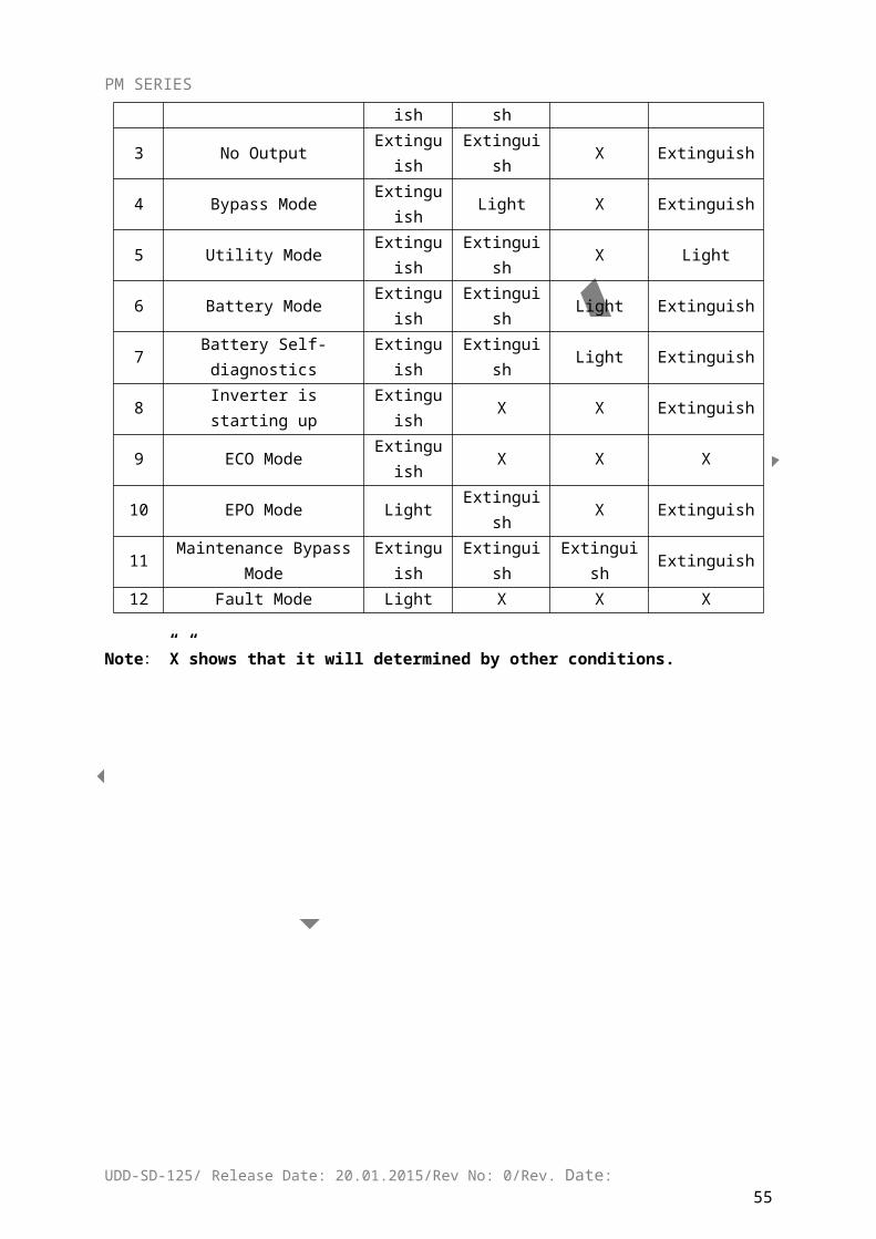
PM SERIES
Appendix 2 UPS message table
1. The Inner Code is applied to this Series. The following format block is Inner Code display on LCD:
AAAA-AAAA BBBB-BBBB EEFF CCCC-CCCC DDDD-DDDD
2. The part of Inner Code means
AAAA-AAAA(Rectifier State):
Axxx-xxxx
8 9 A B C D E F Int. Input Switch closed
4 5 6 7 C D E F Rectifier Activated
2 3 6 7 A B C
E F Emergency Power off
1 3 5 7 9 B D F Rectifier current Limit
xAxx-xxxx
8 9 A B C D E F Input Power work on
4 5 6 7 C D E F Power by Input
2 3 6 7 A B C
E F Battery Test
1 3 5 7 9 B D F Battery Charge
xxAx-xxxx 8 9 A B C D E F P-Battery Boost Charge
4 5 6 7 C D E F N-Battery Boost Charge
2 3 6 7 A B C
E F
1 3 5 7 9 B D F
xxxA-xxxx
8 9 A B C D E F
4 5 6 7 C D E F
2 3 6 7 A B C
E F
1 3 5 7 9 B D F
xxxx-Axxx
8 9 A B C D E F communication connected
4 5 6 7 C D E F
2 3 6 7 A B C
E F
1 3 5 7 9 B D F
xxxx-xAxx 8 9 A B C D E F
4 5 6 7 C D E F
2 3 6 7 A B C
E F
1 3 5 7 9 B D F
xxxx-xxAx
8 9 A B C D E F
4 5 6 7 C D E F
2 3 6 7 A B C
E F
1 3 5 7 9 B D F
xxxx-xxxA 8 9 A B C D E F
4 5 6 7 C D E F
2 3 6 7 A B C
E F
1 3 5 7 9 B D F
UDD-SD-125/ Release Date: 20.01.2015/Rev No: 0/Rev. Date:56
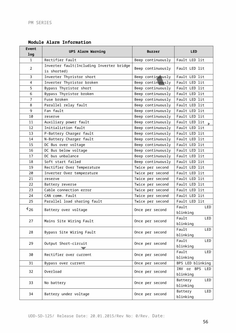
PM SERIES
BBBB-BBBB(Inverter State):
Bxxx-xxxx
8 9 A B C D E F Int. bypass Switch Closed
4 5 6 7 C D E F Int. output Switch Closed
2 3 6 7 A B C
E F Manu-Bypass Switch Closed
1 3 5 7 9 B D F Ext. bypass Switch Closed
xBxx-xxxx
8 9 A B C D E F Ext. output Switch Closed
4 5 6 7 C D E F 00:Shut Down,01:Inv starting,10:Inv work on ,but No Output 11:Normal Output2 3 6 7 A B C E F
1 3 5 7 9 B D F Output by Inv
xxBx-xxxx
8 9 A B C D E F Output by Bypass
4 5 6 7 C D E F Cue: Interval Transfer2 3 6 7 A B
C E F Cue: turn-off, System will be
broken
1 3 5 7 9 B D F Cue:trun-off,Parallel will be overloaded
xxxB-xxxx
8 9 A B C D E F Emergency Power off
4 5 6 7 C D E F INV.invalid due to Overload
2 3 6 7 A B C
E F Change Master
1 3 5 7 9 B D F Transfer Times-out
xxxx-Bxxx
8 9 A B C D E F Shutdown Due To Overload
4 5 6 7 C D E F On Bypass Due To Overload
2 3 6 7 A B C
E F Parallel in Bypass
1 3 5 7 9 B D F LBS Activated
xxxx-xBxx 8 9 A B C D E F INV standby
4 5 6 7 C D E F
2 3 6 7 A B C
E F
1 3 5 7 9 B D F
xxxx-xxBx
8 9 A B C D E F Shutdown Due To Overload
4 5 6 7 C D E F On Bypass Due To Overload
2 3 6 7 A B C
E F Parallel in Bypass
1 3 5 7 9 B D F LBS Activated
xxxx-xxxB 8 9 A B C D E F INV standby
4 5 6 7 C D E F
2 3 6 7 A B C
E F
1 3 5 7 9 B D F
CCCC-CCCC(Rectifier Alarm):
UDD-SD-125/ Release Date: 20.01.2015/Rev No: 0/Rev. Date:57
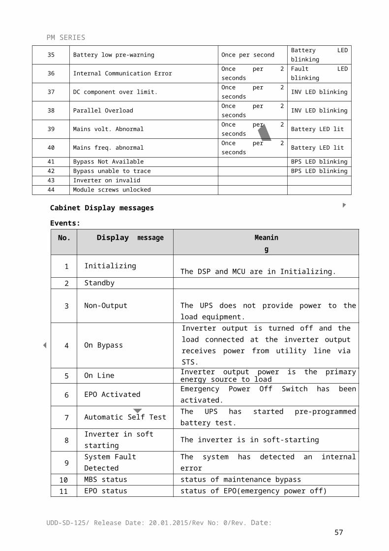
PM SERIES
Cxxx-xxxx
8 9 A B C D E F Rectifier fault
4 5 6 7 C D E F Rectifier over temperature
2 3 6 7 A B C
E F Inverter over temperature
1 3 5 7 9 B D F Rectifier over current
xCxx-xxxx 8 9 A B C D E F Auxiliary power 1 fault
4 5 6 7 C D E F Auxiliary power 2 fault
2 3 6 7 A B C
E F Input Thyristor failed
1 3 5 7 9 B D F Discharge Thyristor failed
xxCx-xxxx
8 9 A B C D E F Charge Thyristor failed
4 5 6 7 C D E F Fan fault
2 3 6 7 A B C
E F Fan Power fault
1 3 5 7 9 B D F DC Bus over voltage
xxxC-xxxx 8 9 A B C D E F DC Bus below voltage
4 5 6 7 C D E F DC bus unbalance
2 3 6 7 A B C E F Mains Site Wiring Fault
1 3 5 7 9 B D F Soft start failed
xxxx-Cxxx
8 9 A B C D E F Input Neutral line missing
4 5 6 7 C D E F Battery reverse
2 3 6 7 A B C
E F No battery
1 3 5 7 9 B D F P-Battery Charger fault
xxxx-xCxx 8 9 A B C D E F N-Battery Charger fault
4 5 6 7 C D E F Battery under voltage
2 3 6 7 A B C
E F Battery over voltage
1 3 5 7 9 B D F Battery low pre-warning
xxxx-xxCx
8 9 A B C D E F Mains freq. abnormal
4 5 6 7 C D E F Mains volt. Abnormal
2 3 6 7 A B C
E F
1 3 5 7 9 B D F
xxxx-xxxC 8 9 A B C D E F
4 5 6 7 C D E F
2 3 6 7 A B C
E F
1 3 5 7 9 B D F
DDDD-DDDD(Inverter Alarm):Dxxx-xxxx
8 9 A B C D E F Inverter fault
4 5 6 7 C D E F Inv. IGBT bridge shorted
2 3 6 7 A B C
E F Inverter Thyristor short
1 3 5 7 9 B D F Inverter Thyristor broken
xDxx-xxxx 8 9 A B C D E F Bypass Thyristor short
UDD-SD-125/ Release Date: 20.01.2015/Rev No: 0/Rev. Date:58
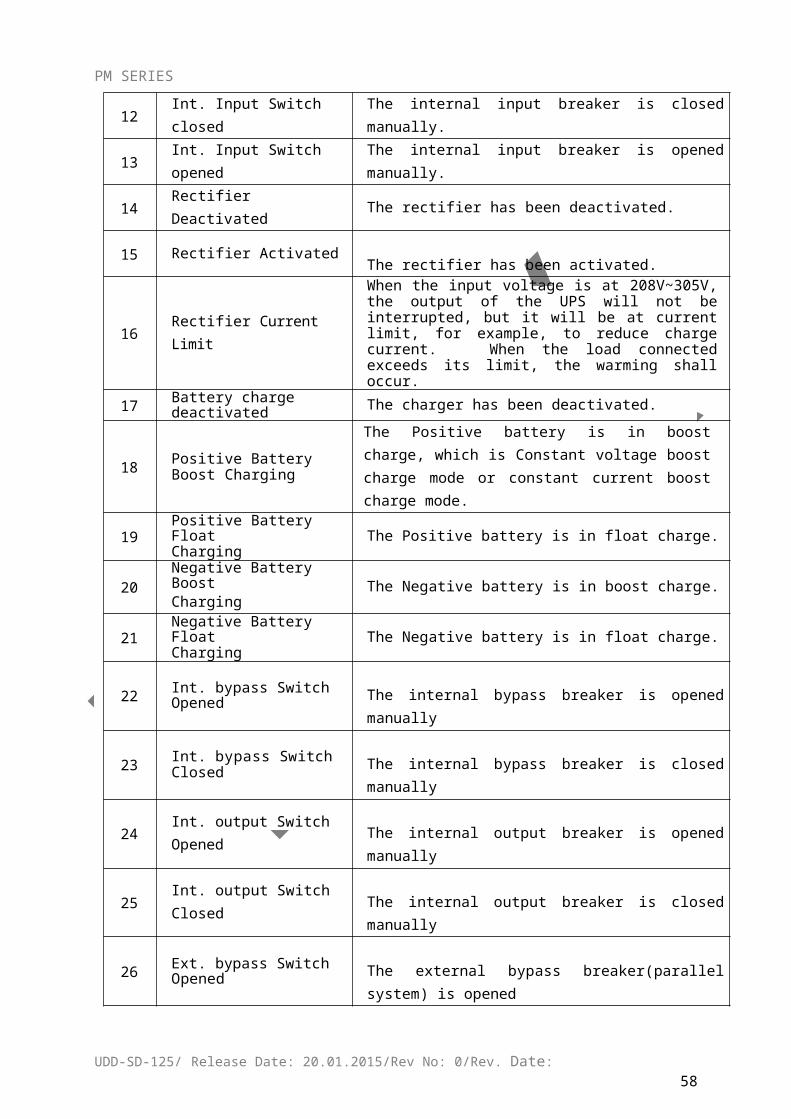
PM SERIES
4 5 6 7 C D E F Bypass Thyristor broken
2 3 6 7 A B C
E F CAN comm. Fault
1 3 5 7 9 B D F Parallel load sharing fault
xxDx-xxxx
8 9 A B C D E F Bypass Site Wiring Fault
4 5 6 7 C D E F System not Sync. to Bypass
2 3 6 7 A B C
E F Bypass unable to trace
1 3 5 7 9 B D F Bypass Not Available
xxxD-xxxx 8 9 A B C D E F IGBT over current
4 5 6 7 C D E F Fuse broken
2 3 6 7 A B C
E F Cable connection error
1 3 5 7 9 B D F Parallel relay fault
xxxx-Dxxx
8 9 A B C D E F LBS Not SYNC.
4 5 6 7 C D E F Initializtion fault
2 3 6 7 A B C
E F Inverter on invalid
1 3 5 7 9 B D F Overload
xxxx-xDxx 8 9 A B C D E F Parallel Overload
4 5 6 7 C D E F DC component over limit.
2 3 6 7 A B C
E F Bypass over current
1 3 5 7 9 B D F Feedback protection
xxxx-xxDx
8 9 A B C D E F BUS voltage abnormal
4 5 6 7 C D E F
2 3 6 7 A B C
E F
1 3 5 7 9 B D F
xxxx-xxxD
8 9 A B C D E F
4 5 6 7 C D E F
2 3 6 7 A B C
E F
1 3 5 7 9 B D F
EE(Inside Monitor):
Ex 8 9 A B C D E F generator Connect
4 5 6 7 C D E F Shutdown Due To Batt. Low
2 3 6 7 A B C
E F Time to turn on
1 3 5 7 9 B D F Time to turn off
xE 8 9 A B C D E F timing self test start
4 5 6 7 C D E F Surge protection active signal, from monitoring board IO
2 3 6 7 A B C
E F battery monitoring system connected
1 3 5 7 9 B D F system unregistered
FF(Monitoring)
UDD-SD-125/ Release Date: 20.01.2015/Rev No: 0/Rev. Date:59
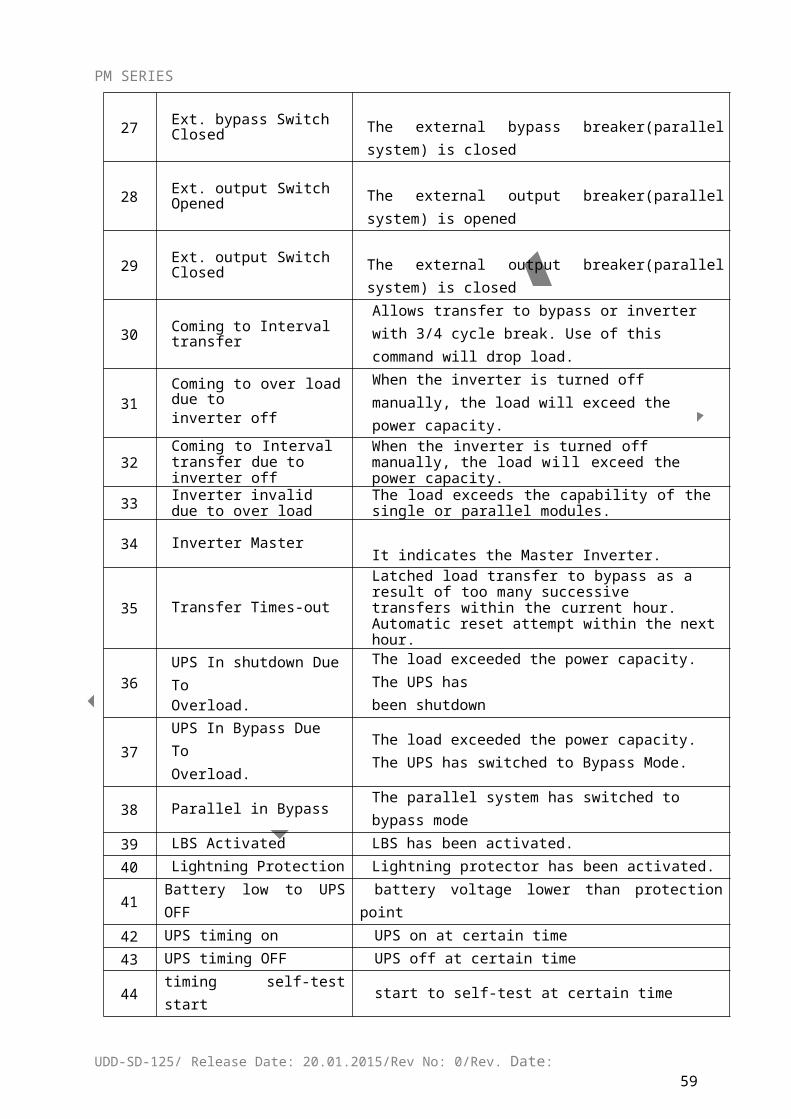
PM SERIES
Fx 8 9 A B C D E F Battery Fault
(from battery monitoring)
4 5 6 7 C D E F Battery over temperature (from battery monitoring)
2 3 6 7 A B C E F Battery over voltage (from battery monitoring)
1 3 5 7 9 B D F Battery under voltage(from battery monitoring)
xF 8 9 A B C D E F External Fire Alarm
(from monitoring board IO) 4 5 6 7 C D E F External Smoke Alarm
(from monitoring board IO)
2 3 6 7 A B C
E F UPS model wrong1 3 5 7 9 B D F time up for suggested
maintenance
Appendix 3 Problems and Solution
In case the UPS cannot work normally, it might be wrong in installation, wiring or operation. Please check these aspects first. If all these aspects are checked without any problem, please consult with local agent right away and provide below information.
1. Product model name and serial number, which can be found in LCD display.
2. Try to describe the fault with more details, such as LCD display info, LED lights status, etc.
Read the user manual carefully, it can help a lot for using this UPS in the right way. Some FAQ (frequently asked questions) may help you to troubleshoot your problem easily.
No. Problem Possible reason Solution
1 LCD not display The network cable is not Connect the network cable and
UDD-SD-125/ Release Date: 20.01.2015/Rev No: 0/Rev. Date:60
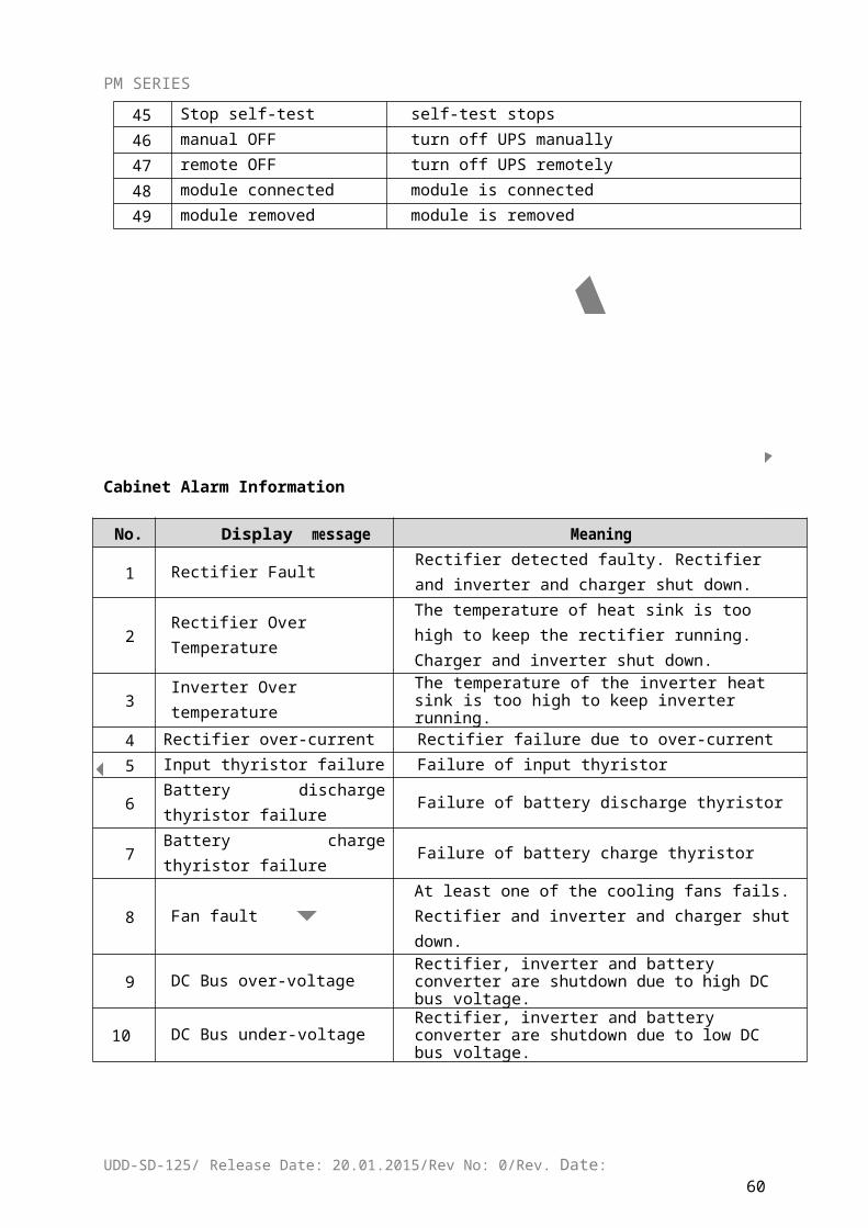
PM SERIES
fixed properly or the telephone line of the front door is not fixed properly.
telephone cable properly.
2 LCD Blue screen LCD is Interference Take out the cable and insert back properly
3
Utility is connected but the UPS cannot be powered ON.
Input power supply is not connected;Input voltage low;The input switch of the module is not switched on.
Measure if the UPS input voltage/frequency is within the window. Check if all modules input are switched on
4
Utility normal but Utility LED does not light on, and the UPS operates at battery mode
The input breakers of the Modules are not switched on;input cable is not well connected
Switch on the input breaker;Make sure the input cable is well connected.
5
The UPS does not indicate any failure, but output do not have voltage
Output cable does not well connected
Make sure the output cable is well connected.
6The UPS module cannot transfer to bypass or inverter
Module does not well inserted;The left coronal screw is not tight.Output breaker do not switch on
Pull out the module and insert again;Tighten the screw;Switch on the output breaker.
7The UPS module fault LED remains ON
The module is already damaged
Take out this module, replace with a new module.
8
Utility LED is flashingUtility voltage exceeds UPS input range.
If the UPS operates at battery mode, please pay attention to the remaining backup time needed for your system.
9
Battery LED is flashing but no charge voltage and current
Battery breaker does not switch on, or batteries are damaged, or battery is reversely connected.Battery number and capacity are not set correctly.
Switch on the battery breaker. If batteries are damaged, need to replace whole group batteries, Connect the battery cables correctly;Go to LCD setting of the battery number and capacity, set the correct data.
10
Buzzer beeps every 0.5 seconds and LCD display “output overload”
Overload remove some load
11Buzzer long beeps, LCD display “output short circuit”
The UPS output is in short circuit
Make sure the load is not in short circuit, and then restart the UPS.
12The LED of the Module with RED light
The module is not inserted properly.
Pull out the module and insert properly.
13 The UPS only works on bypass mode
The UPS is set to ECO mode, or the transfer times to
Set the UPS working mode to Single Module type(non-parallel) or to reset
UDD-SD-125/ Release Date: 20.01.2015/Rev No: 0/Rev. Date:61
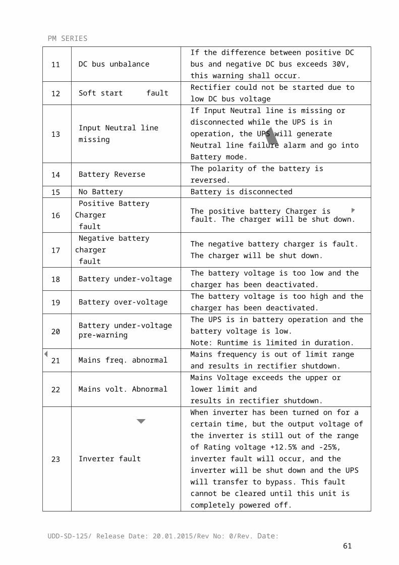
PM SERIES
bypass mode are limited. the times of transferring to bypass or re-start the UPS
14 Cannot Black start
Battery switch is not properly closed; Battery fuse is not open; Or Battery low
Close the battery switch; Change the fuse; Recharge the battery
15
Buzzer beeps continuously and LCD indicates Rectifier fault or output fault
UPS is out of orderConsult with your local agent for repair
Appendix 4 RS232 communication port definition
Definition of Male port:
Connection between PC RS232 port and UPS RS232 port
PC RS232 port UPS RS232 port
Pin 2 Pin 2 UPS send,PC receive
Pin 3 Pin 3 PC send,UPS receive
Pin 5 Pin 5 ground
Available function of RS232
Monitor UPS power status.
Monitor UPS alarm info.
Monitor UPS running parameters.
Timing off/on setting.
RS-232 communication data format
Baud rate ---------- 2400bps
Byte length ---------- 8bit
UDD-SD-125/ Release Date: 20.01.2015/Rev No: 0/Rev. Date:62
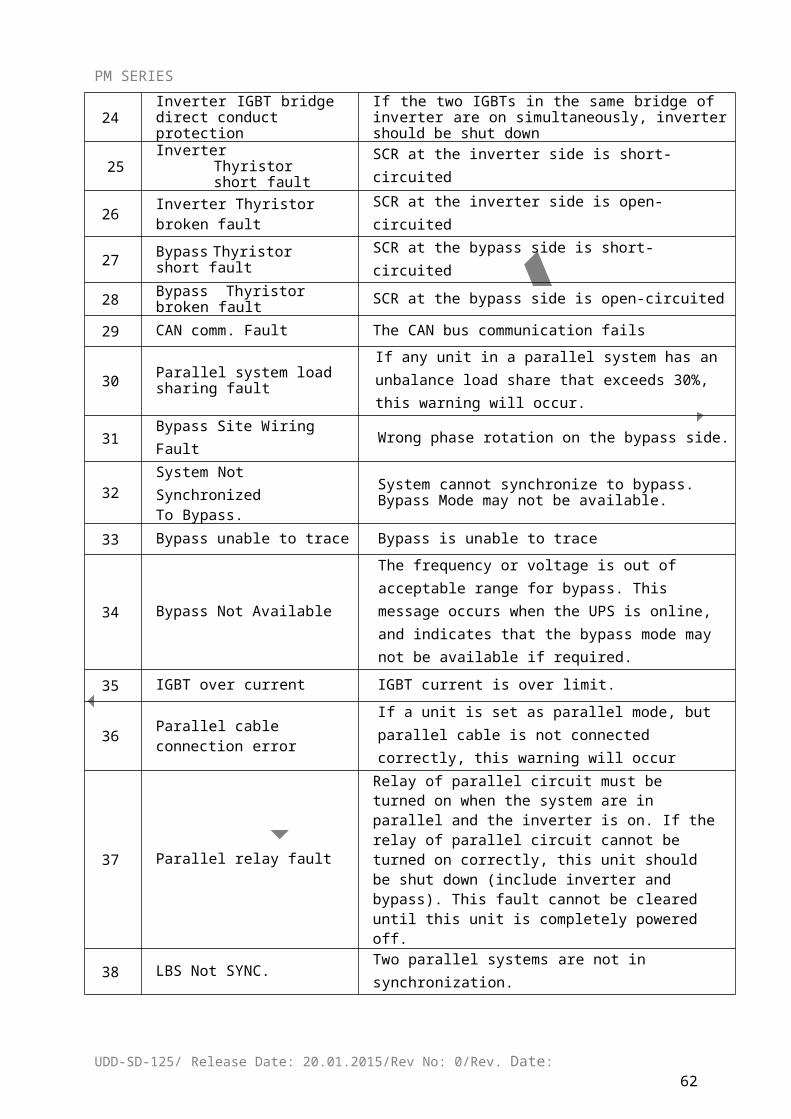
PM SERIES
End bit ---------- 1bit
Parity check ---------none
CAUTION!
RS232 & RS485 ports cannot be used at the same time.
Appendix 5 RS485 communication port definition
Definition of port:
Connection between the Device’s RS485 port and UPS RS485 port.
device(RJ45) UPS(RJ45) Description
Pin 1/5 Pin 1/5 485+ “A”
Pin 2/4 Pin 2/4 485 - “B”
Available function of RS485
Monitor UPS power status.
Monitor UPS alarm info.
Monitor UPS running parameters.
Timing off/on setting.
RS485 communication data format
Baud rate ---------- 2400bps
Byte length ---------- 8bit
End bit ---------- 1bit
Parity check ---------none
CAUTION!
RS232 & RS485 ports cannot be used at the same time.
Appendix 6 BAT_T communication port definition
UDD-SD-125/ Release Date: 20.01.2015/Rev No: 0/Rev. Date:63
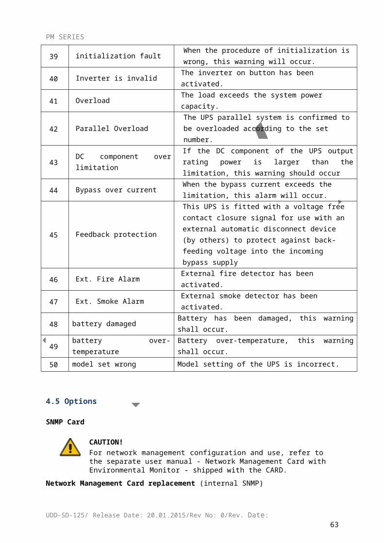
PM SERIES
Definition of port:
Connection between the BAT_T box port and UPS2’s BAT_T port. (RC77002)
Temperature sensor(RJ45) UPS2 BAT_T(RJ45) Description
Pin 1/5 Pin 1/5 TX
Pin 2/4 Pin 2/4 RX
Pin 7 Pin 7 12V
Pin 8 Pin 8 GND
Connection between the BAT_T box port and UPS2’s BAT_T port. (UHTWSC3)
Temperature sensor UPS2 BAT_T(RJ45) Description
Pin 2 Pin 1/5 BAT_T signal
Pin 1 Pin 7 12V
Pin 3/4 Pin 8 GND
Available function of BAT_T
Battery environment temperature monitoring.
Charging voltage modulation depending on batteries’ temperature
UDD-SD-125/ Release Date: 20.01.2015/Rev No: 0/Rev. Date:64
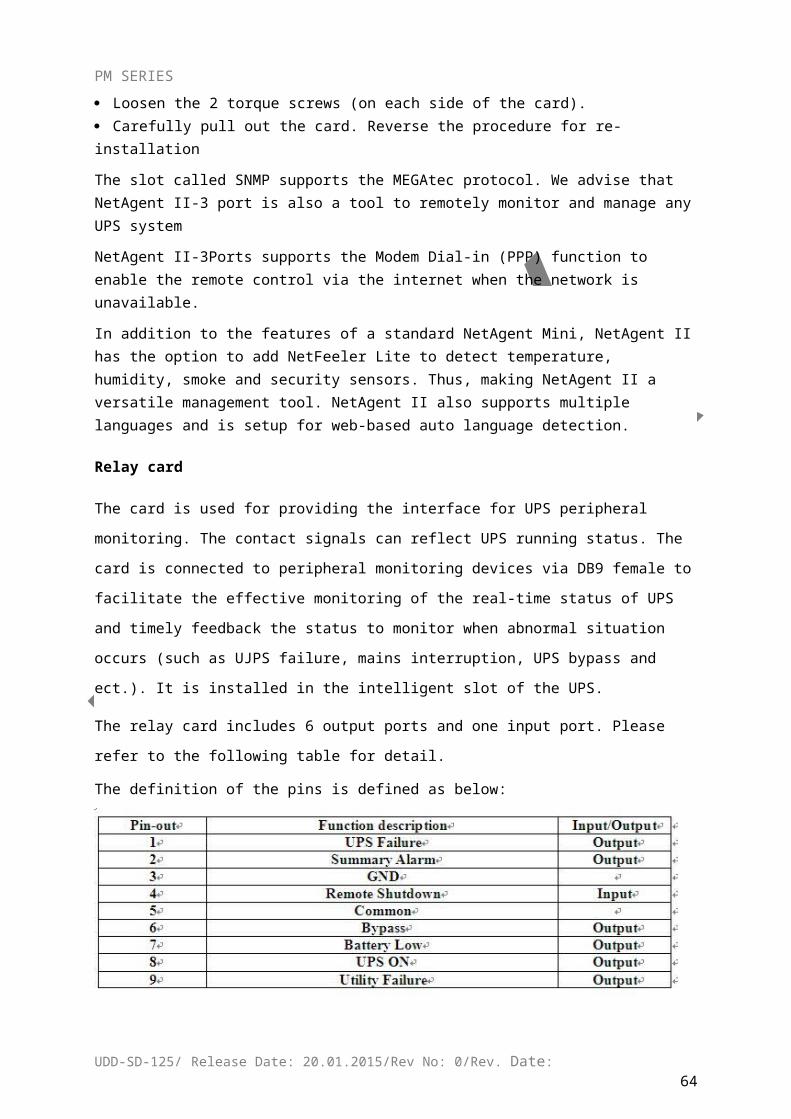
PM SERIES
Appendix 7 Drycontact port definition
Definition of port:
Drycontact(RJ45) Description
Pin 1/5 12V
Pin 2/4 DRY_GENER
Pin 7 DRY_BP_O
Pin 8 DRY_BP_S
Appendix 8 REPO instruction
Definition of port:
Connection diagram:
Connection between the button and UPS REPO port.
Button UPS REPO Description
Pin 1 Pin 1 GND
Pin 2 Pin 2 EPO
UDD-SD-125/ Release Date: 20.01.2015/Rev No: 0/Rev. Date:65
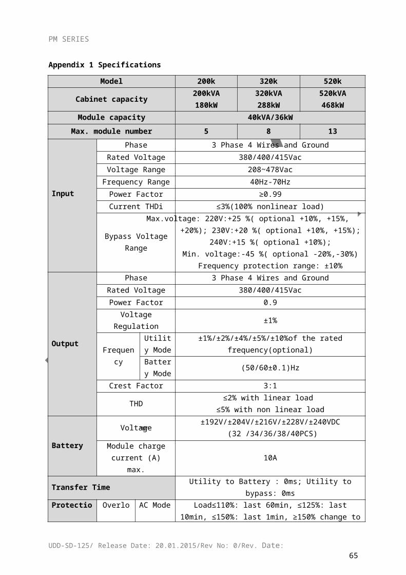
PM SERIES
In addition to the local EPO push button on the front panel of the UPS (that stops operation of
that module when pressed for more than 3 second), the UPS also supports a remote emergency
stop (REPO).
A remote emergency stop switch (Dry contact signal and “normally open” - not provided) can
be installed in a remote location and connection through simple wires to the REPO connector.
The remote switch can be connected to several UPS’s in a parallel architecture allowing the
user to stops all units at once.
Additionally, a second system (not provided) can be connected to the remote switch to
disconnect the main input and the secondary (bypass) input sources
Appendix 9 LBS communication port definition
Definition of port:
Connection between the UPS1’s LBS1 port and UPS2’s LBS2 port.
UPS1 LBS1(RJ45) UPS2 LBS2(RJ45) Description
Pin 1/5 Pin 1/5 LBS_BPSIDE_BC
Pin 2/4 Pin 2/4 LBS_TRACE_BC
Pin 8 Pin 8 GND
Available function of LBS
The output power of two or more UPS in non-parallel system should be synchronized with
each other.
The output phase of two or more UPS in non-parallel system should be synchronized with each
other.
CAUTION!
Two or more LBS cables must be used to form a ring when two or more LBS in
non-parallel system. And the cables must use horizontal line.
UDD-SD-125/ Release Date: 20.01.2015/Rev No: 0/Rev. Date:66
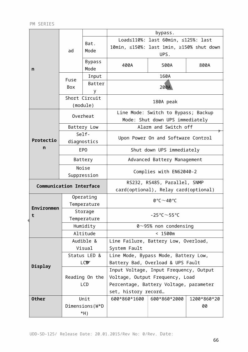
PM SERIES
5 GUARANTEE
5.1 Terms of Guarantee
Our products are under a two-year guarantee starting from the date of delivery against malfunctions resulting from production, material and workmanship faults. Malfunctions due to such type of faults will be removed without claiming any price of workmanship or spare parts to be replaced.
Whether aforementioned malfunctions originate from usage faults or not are determined with a report to be issued by service stations, if there exists no service stations, by one of seller, dealer, agency, representative, importer or manufacturer or producer of those products respectively.
Repair time of defective products is twenty business days at most. This period starts from the date when products are delivered to one of seller, dealer, agency, representative, importer or one of manufacturer or producer. Provided that products break down within the period of guarantee, the time passing during the repair process is added to the guarantee time. Provided that faults of products cannot be removed within ten business days, manufacturer-producer or importer is obliged to assign another product having similar features for the use of consumers until the faulty product has been repaired.
Even though consumers exercise their repair rights, they can claim free replacement of products, refund or price discount at the rate of faultin the events;
That, besides, the product,as of the date when the product is delivered to the consumer, breaks down four times a year or six times within the guarantee period to be determined by the manufacturer-producer and/or importer at least, on the condition of being in guarantee period, such malfunctions perpetuate passing over;
That maximum time required for the repair of products is exceeded; That repair of the malfunction is determined as impossible through a
report to be issued by service station, if there exists no service station, one of seller, dealer, agency, representative, importer or manufacturer or producer of the company respectively.
The consumer is, on demand, obliged to submit guarantee certificate in terms of repairs or replacements within the scope of guarantee.
It is essential that you definitely perform damage control over external packaging before receiving the products to be sent through freight. In the event of any damage, delivery person must be made to prepare a “damage determination record”. (For example; duringthe delivery process, the product has been checked and seen that is damaged.)
UDD-SD-125/ Release Date: 20.01.2015/Rev No: 0/Rev. Date:67
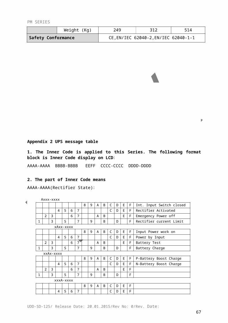
PM SERIES
After the damage determination record has been issued, we request you to inform the MAKELSAN head office of the case. Products to be received from freight by signature means that products have been received completely and without no damage.
Repairs of plug-and-play products in the places where no service point is around are performed in the factory of MAKELSAN or the nearest service point according to the direction to be made by the MAKELSAN head office. Defective product is delivered by hand to the nearest service point or to the contracted freight company in its original packaging to be sent to the factory of MAKELSAN according to the direction to be made by the MAKELSAN head office. For malfunctions in the scope of guarantee, shipment fees are under the responsibility of MAKELSAN on the condition that products are delivered to the contracted freight company.
The device must be sent as packed in its original packaging as long as it is not desired by the service. Original packaging of devices should be preserved in order to use them for shipment of devices in terms of repairs to occur. Otherwise, no responsibility is assumed with regards to any troubles to be experienced.
All defective products to be delivered by hand or through freight are to meet the necessary shipment requirements. (Anti-static protective, bubble wrap or box etc.)It is essential that legible barcode serial number belonging to the product be on the product. Otherwise, it is not covered in the scope of the guarantee.
It is essential that products to be sent through freight definitely be together with delivery note, and that serial/model/malfunction details be written on delivery note to be sent (for example, breakdown report form), and that packaging content match with the products specified in the delivery note. Otherwise, freight is not accepted.
The use of theGuarantee Certificate, submitted together with products with MAKELSAN trademark,is permitted by the T.R. Ministry of Industry and Commerce and General Directorate of Protection of Competition with no……. in accordance with the law, with no. 4077, and the notification, with no. TRKGM-95/116-117, issued basing the aforementioned law. MAKELSAN acknowledges and undertakes to obey the liabilities determined by the laws and legislations.
5.2 Cases Not Covered by the Guarantee
Breakdowns resulting from the use of products contrary to the issues or the environment conditions (temperature, humidity etc.) specified in the user manual are not covered in the scope of guarantee.
Damages and breakdowns resulting from the use of software, hardware, interface, accessories or consumables apart from those used together with products or recommended ones; changing place, wrong and insufficient maintenance, calibration or use; its operation contrary to environment specifications published for products; insufficiency of air installation; use of products in ambient having excessive humid or temperature; its operation in environment harmful for electrical circuits and abrasive;
UDD-SD-125/ Release Date: 20.01.2015/Rev No: 0/Rev. Date:68
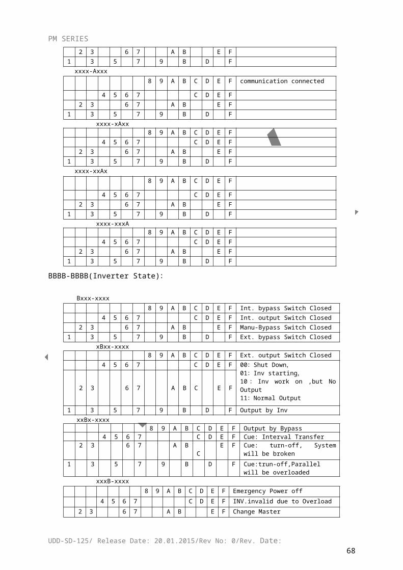
PM SERIES
and accidents, impacts, electric, shipment, natural disasters, not limited to the ones listed above, are not covered in the scope of product guarantee.
In the general examination performed during the breakdown acceptance process, certain troubles causing products not to be covered in the scope of guarantee might not be understood. Provided that such faults come up in the detailed examination to be performed via technical service equipment, products are returned to customers.
Products not covered in the scope of guarantee can, on demand of customer, be treated in a fee-paying way within the bounds of possibilities of the authorized service. Products out of the scope of guarantee, repairs of which are not possible are returned to customers.
Damages and breakdowns resulting from treatments, internally or externally tampering, efforts to repair and spare part replacement of products, without approval of MAKELSAN, and those resulting from treatment of unauthorized service/dealer/person/establishment, are not covered in the scope of guarantee. Breakdown, cracks, scratches and wear, corrosion and dust to occur in time and by use in the outer surfaces of products (cabinet, cover, and front panel) are not covered in the scope of guarantee.
In the event that original serial numbers, guarantee labels and stamps on products are removed or distorted, products are not covered in the scope of guarantee. No guarantee is issued against the use of products for any other purpose, apart from those specified in introduction or manual of products.
Shelf lives of VRLA batteries are 6 months under the ambient temperature of 15 °C and 3
months under the ambient temperature of 25 °C.
It is compulsory that systems to be purchased be commissioned within 3 months.
UDD-SD-125/ Release Date: 20.01.2015/Rev No: 0/Rev. Date:69
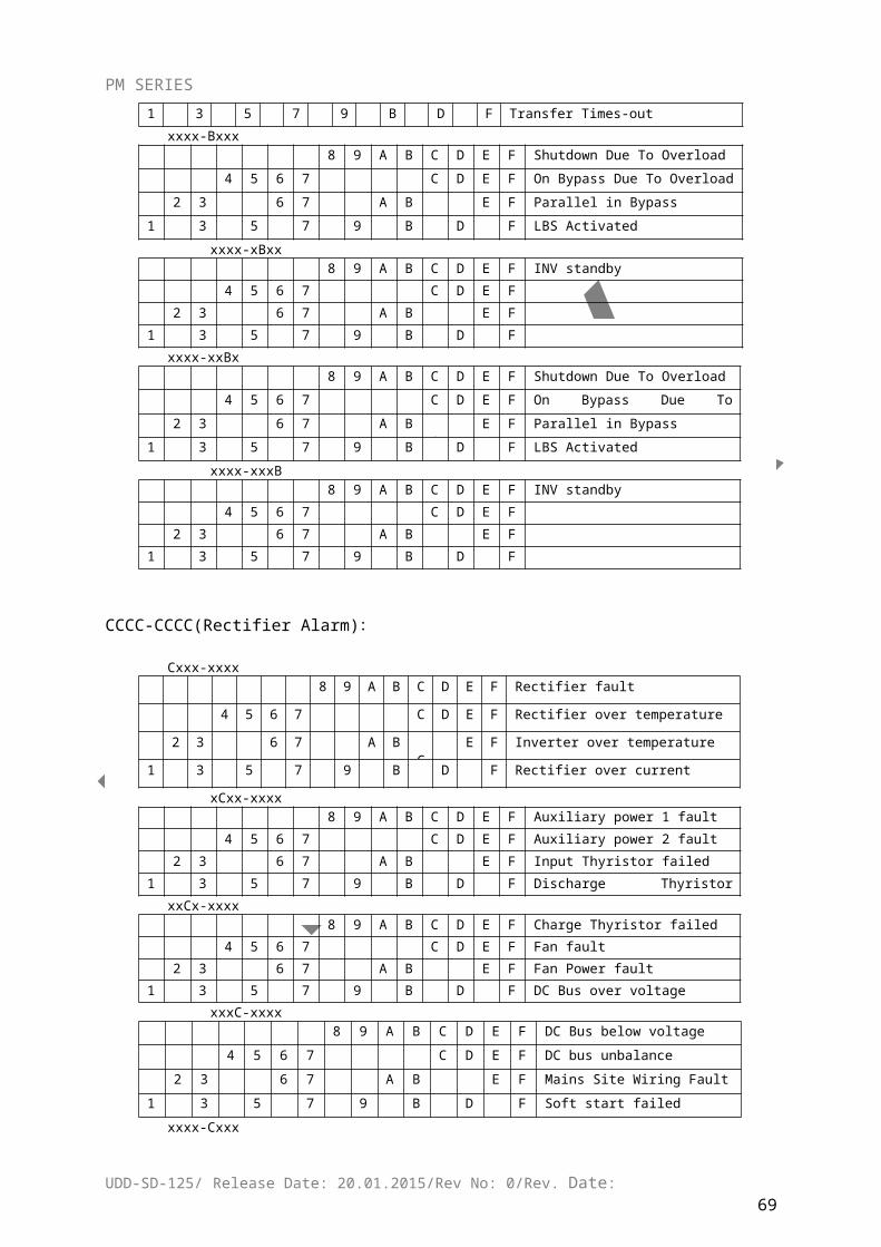
PM SERIES
UDD-SD-125/ Release Date: 20.01.2015/Rev No: 0/Rev. Date:70
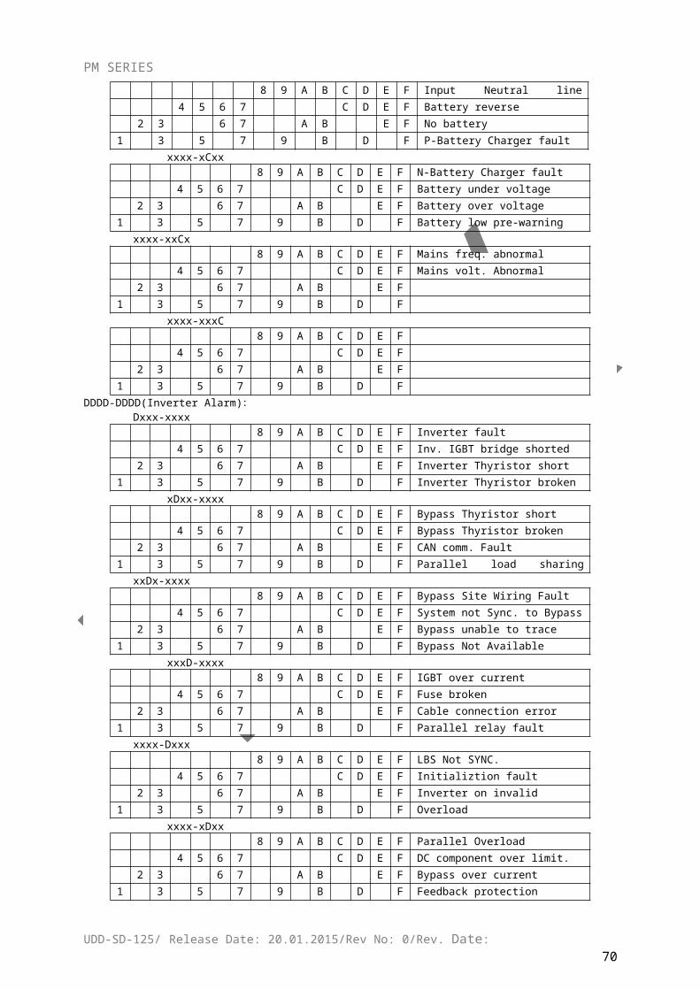
CERTIFICATE OF GUARANTEE
NOTICE
1 – Guarantee period starts from the delivery date of the product and lasts………..years.
2 – The whole product, including all its parts are under the guarantee of our company.
3 – Provided that the product breaks down within the period of guarantee, the time passingduring the repair process is added to the guarantee time. Repair time of the product is …….business days at most. This period starts from the date when the malfunction related to the product is informed to the service station, if there exists no service station, to one of seller, dealer, agency, representative, importer or one of manufacturer. Provided that the fault of industrial product cannot be removed within 10 business days, manufacturer or importer is obliged to assign another industrial product having similar features for the use of the consumer until the faulty product has been repaired.
4 – Provided that the product breaks down due to materials and workmanship or assembly faultswithin the period of guarantee, the product is repaired without claiming any charge for workmanship, any price for spare part replacement or any fee under any name.
5 – The product will be replaced without any charge in the events;
- That passing over the product perpetuates due to the fact that the product repeats thesame malfunction more than twice or different malfunctions occur more than four timesin a year starting from the delivery date, on the condition of being in guarantee period;
- That maximum time required for the repairment of the product is exceeded;- That, if there exists no service station, the repair of the malfunction is determined as
impossible through a report to be issued one of seller, dealer, agency, representative, importer or manufacturer of the product respectively.
6 - Malfunctions resulting from the use of the product contrary to the issues specified in the user manual of the product are not covered in the scope of guarantee.
7 –For any trouble that may come up in terms of the Certificate of Guarantee, the Ministry of Industry and Commerce, General Directorate of Protection of Consumer and Competition can be applied.
8 – Under no circumstances shall the customer treat the product with the aim of repair, apart from MAKELSAN authorized service personnel.
9 – Damages and results originating from the violation of the 8 th Article shall be invoiced to the customer.
The use of herein the certificate is permitted by the T.R. Ministry of Industry andCommerce and General Directorate of Protection of Consumers and Competition inaccrordance with the Law on the Protection of Consumers, with no. 4077, and the Notification Concerning the Application Principles of Guarantee Certificate, issued basing the aforementioned law.
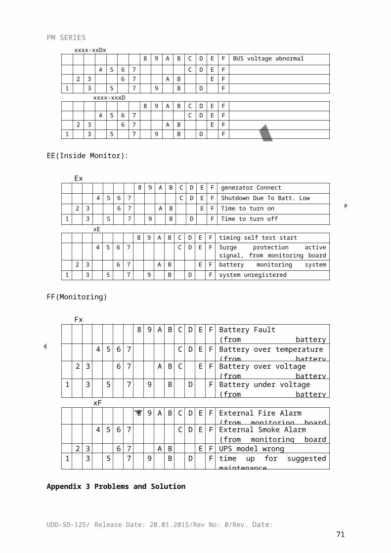
6 CONTACT INFORMATION
www.makelsan.com.tr
Headquarter: İstanbul Deri Organize Sanayi Bölgesi 2. Yol I -5 Parsel 34956 Tuzla/ İstanbulTel : 0216 428 65 80Fax : 0216 327 51 64E-mail : [email protected]
İzmir Office : Halkapınar Mah. 1348 Sok. 2AE Keremoğlu İş Merkezi Yenişehir – İzmirTel : 0232 469 47 00Fax : 0232 449 47 00E-mail : [email protected]
Ankara Office : Mustafa Kemal Mah. 2157 Sok. No:4/6 Çankaya-AnkaraTel : 0312 219 82 35/37Fax : 0312 219 82 36E-mail : [email protected]
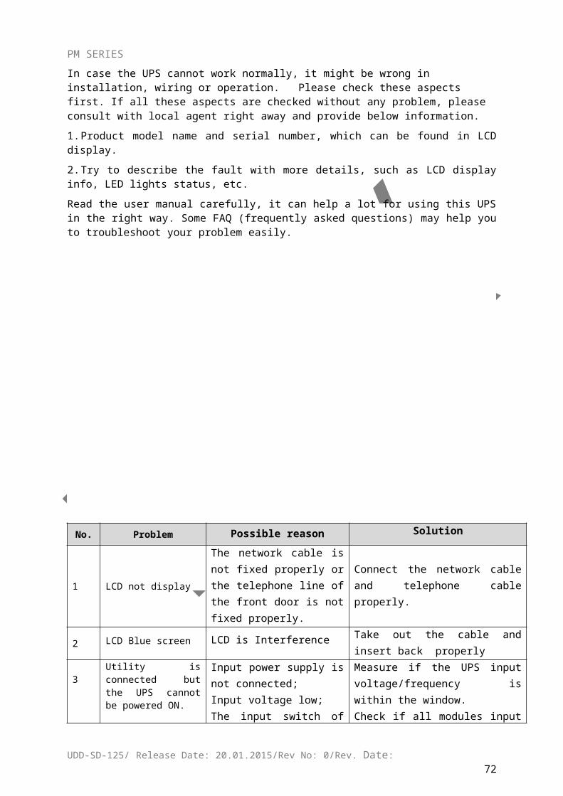
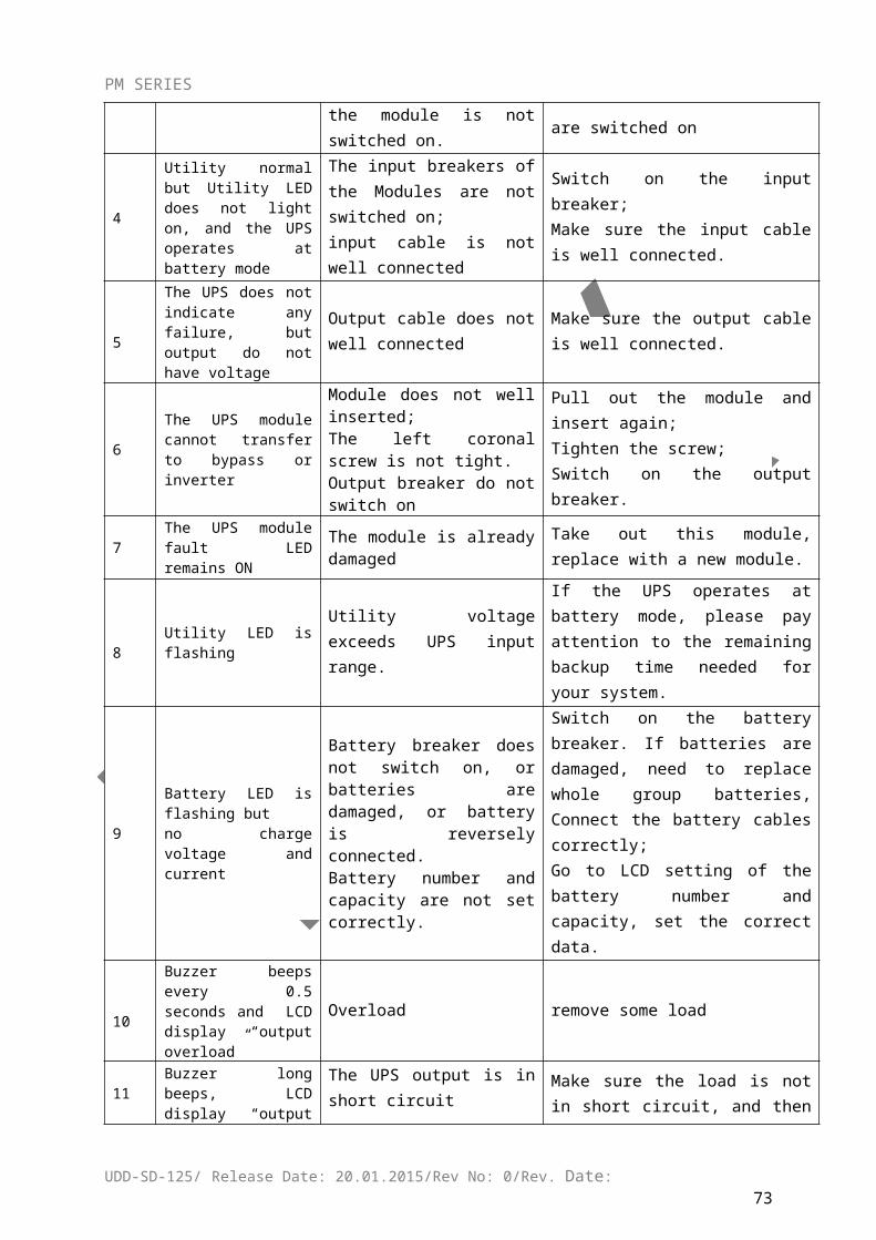