Embed Size (px)
Citation preview

EACO GUIDELINES FOR QUALITY OF SERVICE IN MOBILE AND FIXED NETWORKS FOR VOICE SERVICE
PART 1: DEFINITIONS OF QOS PARAMETERS OF VOICE SERVICE IN
MOBILE AND FIXED NETWORKS
1
TABLE OF CONTENTS1. Introduction...................................................................................................................................................3
2. Scope.............................................................................................................................................................3
3. REFERENCES..............................................................................................................................................3
4. Abbreviations and Acronyms........................................................................................................................4
5. Definition of Terms.......................................................................................................................................5
6. Quality of Service Background......................................................................................................................5
6.1. End-to-End QoS...................................................................................................................................5
6.1.1. Relationship between QoS and Performance...................................................................................6
6.1.2. Relationship between QoS and QoE................................................................................................7
6.2. QoS Models in Standardization Recommendation...............................................................................9
6.2.1. Model of Recommendation ITU-T G.1000......................................................................................9
6.2.2. Model of Recommendation ITU-T E.800......................................................................................11
6.2.3. Phase oriented Aspect Model.........................................................................................................12
7. Quality of Service Parameters.....................................................................................................................13
7.1. Mobile Networks...............................................................................................................................13
7.1.1. Call Setup Success Rate (CSSR)....................................................................................................13
7.1.2. Call setup time (CST)....................................................................................................................15
7.1.3. Call Drop Rate (CDR)...................................................................................................................18
7.1.4. Speech Quality...............................................................................................................................18
7.1.5. Service Coverage Area or Radio Network Availability.................................................................18
7.2. Fixed Networks..................................................................................................................................19
7.2.1. Call Setup Success Rate (CSSR)....................................................................................................19
7.2.2. Call Setup Time (CST)..................................................................................................................19
7.2.3. Fault Repair Time (FRT)...............................................................................................................20
8. Harmonization.............................................................................................................................................20
ANNEX 1: Measurement points in Mobile Originating Call (MOC) call set-up procedure in GSM [Ref: ITU-T E.807]......................................................................................................................................................22
ANNEX 2: 3G telephony signalling Flow Chart: Mobile Originated Call (MOC) Establishment Procedure [Ref: ITU-T E.804]............................................................................................................................................23
2
1. INTRODUCTION
The term Quality of Service (QoS) is extensively used today, not just in the telecommunication world in which it has its roots, but increasingly regarding broadband, wireless and multimedia services that are based on the IP protocol. Networks and systems are gradually being designed in consideration of the end-to-end performance required by user applications; however, the term QoS is usually not well-defined, is used loosely or, worst of all, misused. Therefore, guidance is needed on how to understand and apply the term QoS.
The term "Quality of Service" addresses technical as well as non-technical aspects affecting a service. Different concepts and guidance have been developed to cover various interests and viewpoints of all parties of telecommunications service market, i.e. users, service providers, network operators, manufacturers and regulators.
This guideline provides to EACO countries, a guidance for “QoS parameters of the voice call service from end-user perspective in fixed and mobile networks”. The guideline is formed by two documents (Part1: Definitions & Thresholds of QoS Parameters and Part2: Measurement and Statistical Methodologies) but the present document discusses only Part 1. The current document also gives a general background of Quality of Service for Telecommunication service.
2. SCOPEThis guideline covers the QoS of voice service in Mobile and fixed networks communication. This guideline is formed by two parts (Part 1 and 2) as follows:
Part 1: focuses on harmonising “Definitions and Thresholds of QoS Parameters” for EACO member states”.
Part 2: focuses on harmonisation of “Measurement and Statistical methodologies for EACO member states”.
This document covers Part 1 only; part 2 shall be detailed separately. It summarises the QoS background in general and also gives a clear difference between Network Performance, Quality of Service and Quality of Experience. The document also outlines important QoS Models standardised internationally (ITU-T E.800 Model, ITU-T G.1000…).
The “QoS Parameters and Measurements” of Broadband/Internet services (such as HTTP, FTP, Video and so on) for fixed and mobile networks are out of scope of this guideline. They will be discussed in a different guideline.
3
3. REFERENCES
[ITU-T E.800] Recommendation ITU-T E.800 (2008): Definitions of terms related to quality of service
[ITU-T G.1000] Recommendation ITU-T G.1000 (2001): Communications Quality of Service: A framework and definitions
[ITU-T I.350] Recommendation ITU-T I.350 (1993): General aspects of quality of service and network performance in digital networks, including ISDNs
[ITU-T E.804] Recommendation ITU-T E.804 (2014):QoS Aspects for Popular Services in Mobile Networks
[ITU-T E.807] Recommendation ITU-T E.807 (2014): Definitions, associated measurement methods and guidance targets of user-centric parameters for call handling in cellular mobile voice service
[ETSI EG 202 057-2] ETSI EG 202 057-2, User related QoS parameter definitions and measurements; Part 2: Voice telephony, Group 3 fax,modem data services and SMS
4. ABBREVIATIONS AND ACRONYMS
CDR Call Drop RateCST Call Setup TimeCSSR Call Setup Successful RateEACO East Africa Communications Organization GSM Global System for Mobile communicationsHTTP Hyper Text Transfer ProtocolIP Internet ProtocolITU International Telecommunication Union MOC Mobile Originated CallMOS LQO Mean Opinion Score Listening speech Quality ObjectiveMOS Mean Opinion ScoreMS Mobile StationMSC Mobile Switching CentreMSN Mobile Station NumberMTC Mobile Terminated CallNP Network PerformanceQoE Quality of Experience
4
QoS Quality of ServiceQoSD Quality of Service Delivered QoSE Quality of Service ExperiencedQoSO Quality of Service OfferedQoSR Quality of Service RequiredWCDMA Wideband Code Division Multiple Access
5. DEFINITION OF TERMS
End-to-End Quality [ITU-T E.804]: Quality related to the performance of a communication system, including all terminal equipment. For voice services it is equivalent to mouth-to-ear quality.
Network performance [ITU-T E.800]: Is the ability of a network or network portion to provide the functions related to communications between users.
Probing Attempt [ITU-T E.804]: Trial to examine if the service under test works as expected
Quality of Experience (QoE) [ITU-T E.804]: The inclusion of the user himself or herself to the overall quality in telecommunications extends the rather objective Quality of Service to the highly subjective Quality of Experience.
Quality of service [ITU-T E.800]: Is the totality of characteristics of a telecommunications service that bear on its ability to satisfy stated and implied needs of the user of the service.
6. QUALITY OF SERVICE BACKGROUND
In [ITU-T E.800], QoS is defined as follows: “Totality of characteristics of a telecommunications service that bear on its ability to satisfy stated and implied needs of the user of the service”.
Therefore, in general QoS is focused on the service from the user's viewpoint being a complete end-to-end view. The perceived quality of a service is the result of the combined influence of the performance of networks and terminals as well as the perception and expectation of the user.
Accordingly, QoS should take into account both the user's and the service provider's point of view; it should always be judged from these different perspectives.
5
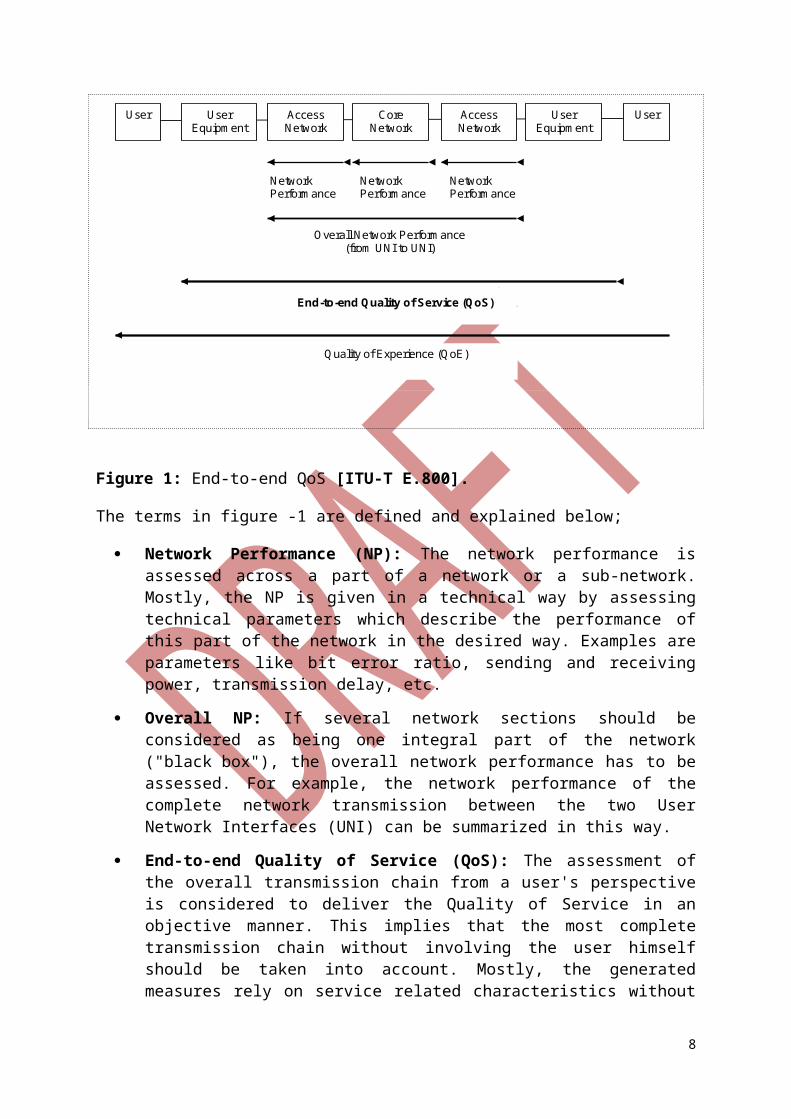
6.1. END-TO-END QOSThe degree of QoS depends on the collective effect of all sub-parts as highlighted in figure -1 below.
Figure 1: End-to-end QoS [ITU-T E.800].
The terms in figure -1 are defined and explained below;
Network Performance (NP): The network performance is assessed across a part of a network or a sub-network. Mostly, the NP is given in a technical way by assessing technical parameters which describe the performance of this part of the network in the desired way. Examples are parameters like bit error ratio, sending and receiving power, transmission delay, etc.
Overall NP: If several network sections should be considered as being one integral part of the network ("black box"), the overall network performance has to be assessed. For example, the network performance of the complete network transmission between the two User Network Interfaces (UNI) can be summarized in this way.
End-to-end Quality of Service (QoS): The assessment of the overall transmission chain from a user's perspective is considered to deliver the Quality of Service in an objective manner. This implies that the most complete transmission chain without involving the user himself should be taken into account. Mostly, the generated measures rely on service related characteristics without knowing any details about the underlying network sections which are required to have an end-to-end service at all.
Quality of Experience (QoE): The inclusion of the user himself or herself to the overall quality in telecommunications extends the rather objective Quality of Service to the highly subjective Quality of Experience. The QoE differs from user to user since it is influenced by personal experiences and expectations of the individual user.
6
User User User Equipment
User Equipment
Access Network
Access Network
Core Network
Network Performance
Network Performance
Network Performance
Overall Network Performance (from UNI to UNI)
End-to-end Quality of Service (QoS)
Quality of Experience (QoE)
6.1.1. RELATIONSHIP BETWEEN QOS AND PERFORMANCE
The network and terminal performance have an influence on the QoS; they represent a part of it. There are intrinsic relationships between QoS and performance parameters.
Performance parameters are used to measure objectively the performance of specific network and terminal elements that have an influence on the resulting end-to-end quality of a service.
The main difference between QoS and network performance is that QoS provides quality information on an end-to-end and service related basis, whereas network performance specifies the technical operations of network and network sections.
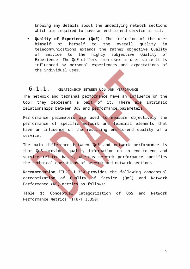
Recommendation ITU-T I.350 provides the following conceptual categorization of Quality of Service (QoS) and Network Performance (NP) metrics as follows:
Table 1: Conceptual Categorization of QoS and Network Performance Metrics [ITU-T I.350]
Quality of Service parameter Network Performance parameterUser oriented Network provider orientedService related attributes Network element and technology related
attributesFocus on user observable effects Focus on planning development (design),
operations and maintenanceObserved at service access points for the users, independent of network process and events
Observed at network connection element boundaries, e.g. relating to protocol specific interface signals
6.1.2. RELATIONSHIP BETWEEN QOS AND QOE
The increased significance of the term QoE is related to the fact that in the past the term QoS was used mostly for only technical concepts focused on networks and networks elements. The definition of QoS, however, does include the degree of satisfaction of a user with a service.
Thus, non-technical aspects are included in the definition of QOS, e.g. the user's environment, user expectations, nature of the content. This is contrary to the initial understanding where most service providers used the term QoS only in relation to the actual user-service interaction to determine whether the user requirements have been met by the service provider (as perceived by the user). In view of this, there is need to consider the definition of QOS that includes the Non-Technical aspects mentioned above.
QoE is defined in [ITU-T P.10] in Appendix I as “the overall acceptability of an application or service, as perceived subjectively by the end-user”. It includes the complete end-to-end system effects (client, terminal, network, services infrastructure, etc) and may be influenced by user expectations and context. Hence the QoE is measured subjectively by the end-user
7
and may differ from one user to the other. However, it is often estimated using objective measurements.
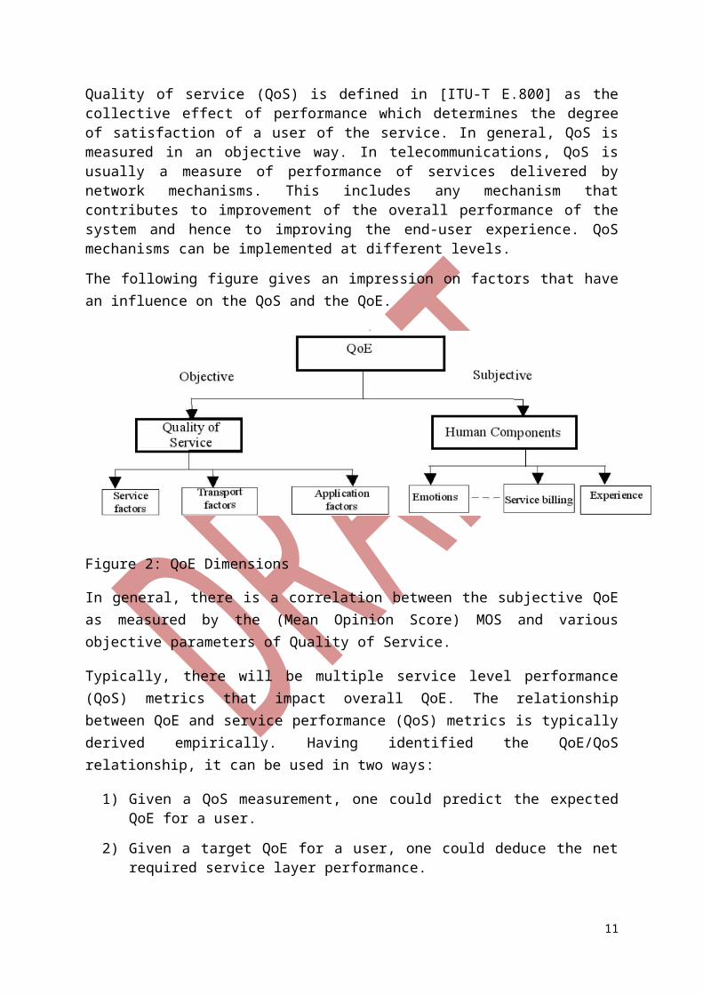
Quality of service (QoS) is defined in [ITU-T E.800] as the collective effect of performance which determines the degree of satisfaction of a user of the service. In general, QoS is measured in an objective way. In telecommunications, QoS is usually a measure of performance of services delivered by network mechanisms. This includes any mechanism that contributes to improvement of the overall performance of the system and hence to improving the end-user experience. QoS mechanisms can be implemented at different levels.
The following figure gives an impression on factors that have an influence on the QoS and the QoE.
Figure 2: QoE Dimensions
In general, there is a correlation between the subjective QoE as measured by the (Mean Opinion Score) MOS and various objective parameters of Quality of Service.
Typically, there will be multiple service level performance (QoS) metrics that impact overall QoE. The relationship between QoE and service performance (QoS) metrics is typically derived empirically. Having identified the QoE/QoS relationship, it can be used in two ways:
1) Given a QoS measurement, one could predict the expected QoE for a user.
2) Given a target QoE for a user, one could deduce the net required service layer performance.
These prediction and deduction steps are built on assumptions and approximations. Due to the complexity of services and the many factors which have an influence on QoS/QoE, there is not a close one-to-one relationship which would allow statements like "If the bandwidth is increased by 200 kbit/s, the rating by the user will rise 0,5 points".
To ensure that the appropriate service quality is delivered, QoE targets should be established for each service and be included early on in system design and engineering processes where they are translated into objective service level performance metrics.
8
Quality of Experience will be an important factor in the marketplace success of services (such as triple-play, voice, data and Video) and is expected to be a key differentiator with respect to competing service offerings. Subscribers to network services do not care how service quality is achieved. What matters to them is how well a service meets their expectations for effectiveness, operability, availability, and ease of use.
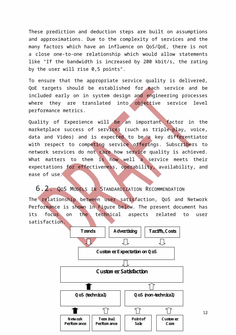
6.2. QOS MODELS IN STANDARDIZATION RECOMMENDATION
The relationship between user satisfaction, QoS and Network Performance is shown in Figure below. The present document has its focus on the technical aspects related to user satisfaction.
Figure 3: Relationship between user satisfaction, QoS and Network Performance
6.2.1. MODEL OF RECOMMENDATION ITU-T G.1000
In [ITU-T G.1000], a four-viewpoint model of QoS has been defined. In general, the model discusses two dimensions: The relationship between a service user, the "customer", and his service provider; and The QoS expectations and the achieved level of QoS for both parties, the customer and the service provider.
Figure 4 describing the different Quality of Service relations is inspired by [ITU-T G.1000].
9
Customer Satisfaction
QoS (technical) QoS (non-technical)
Network Performance
Customer Expectation on QoS
Trends Advertising
Tariffs, Costs
Terminal Performance
Point of Sale
Customer Care
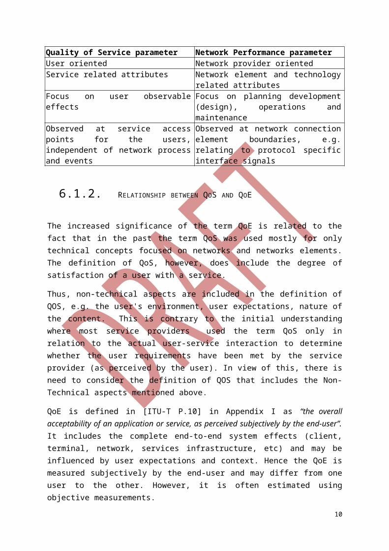
Figure 4: Four-viewpoint model of QoS
The expected and perceived QoS from the user's perspective might be given in more descriptive terms whereas the provider will use more technically oriented terms to handle his offered and achieved level of QoS.
6.2.1.1. QOS REQUIRED BY THE USER (QOSR)The QoS requirements of the user are described in a common, non-technical language. To describe his needs, the user reflects his expectations from an end user's perspective. This means he formulates the requirements he expects from the services delivered over the network. The user needs not to be aware of the technical feasibilities or implementation limitations that may occur.
Depending on the boundary conditions, the required QoS might also be part of contractual terms. The user's QoS requirements are the basis for the QoS level which should be offered by the service provider. The service provider should take the necessary measures to deliver a QoS level which is matching the user's needs.
6.2.1.2. QOS OFFERED BY THE SERVICE PROVIDER (QOSO)The service provider states the QoS level they want to reach. This can be done in two ways:
In a non-technical manner to ease the comprehensibility of the given information towards the user.
In a technical manner to allow an assessment by experts, to allow for basis to set up Service Level Agreements (SLA) or to facilitate technical planning purposes.
For technical purposes, the QoS level is defined by the use of parameter definitions and according values (setting thresholds) which should be reached. This information should be given separately for each kind of offered service (normally under a negotiated methodology).
6.2.1.3. QOS DELIVERED BY THE SERVICE PROVIDER (QOSD)
10
User Service Provider
User’s expected
QoS
Requirements
QoS Delivered
By
Service Provider
QoS Offered
By
Service Provider
QoS Perceived
By
User
The QoS delivered by the service provider reflects the currently achieved state of the QoS. This QoS level again should be described by parameters with assigned values, e.g. from active or passive probing or other kinds of appropriate testing.
The comparison of the offered and the delivered QoS allows assessing the capabilities of the service provider to deliver the promised QoS. Deviations/differences can be made transparent / stated or noted very easily.
6.2.1.4. QOS EXPERIENCED BY THE USER (QOSE)The experienced or perceived QoS reflects the subjective view of the user on his individual situation. The user's satisfaction is one of the main drivers of this kind of QoS.
In general, the perceived QoS is described in a non-technical manner. Service providers can retrieve the level of perceived QoS by executing surveys with their customers or by asking their users for other kind of feedback.
At this stage, the user combines his personal and individual experience with the more technically oriented quality of the delivered services. Overall, his individual Quality of Experience measure is generated. In technical means, QoE and QoS can be mapped on each other.
Besides the technology based factors, further factors have an influence on the QoE of a user: Starting with the signature of the contract, going on with handling of problems by the provider, willingness to fulfil the user's needs and other things up to the cessation/termination of the contract, the complete relationship between provider and user might have an influence on the QoE. Obviously, the relationship experience has an influence on rating issues and makes the mapping of QoS and QoE more complicated because of "hidden factors".
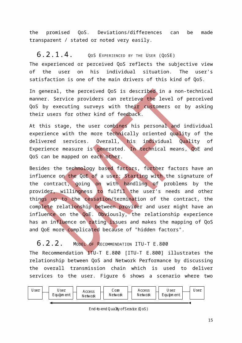
6.2.2. MODEL OF RECOMMENDATION ITU-T E.800The Recommendation ITU-T E.800 [ITU-T E.800] illustrates the relationship between QoS and Network Performance by discussing the overall transmission chain which is used to deliver services to the user. Figure 6 shows a scenario where two mobile users are communicating with each other. In general, the same situation applies also to any other consideration where a user deploys a client-server-like service.
Figure 6: Transmission chain discussed in [ITU-T E.800]
In the depicted case, there are two user equipments and two access networks, one on each end. The core network builds the link between both access networks. It may consist of different networks run by different providers.
11
User User User Equipment
User Equipment
Access Network
Access Network
Core Network
End-to-end Quality of Service (QoS)
Each of the mentioned components has an influence on the achievable QoS level:
If one of the user equipments has limited capabilities, e.g. reduced computational power, this will have an observable effect on the end-to-end QoS.
The same applies to the access networks, where e.g. the bandwidth of the transmission link has a major effect.
Furthermore, if one of the providers linked within the core network violates SLAs between the providers, the end user may realise this by the QoS he perceives.
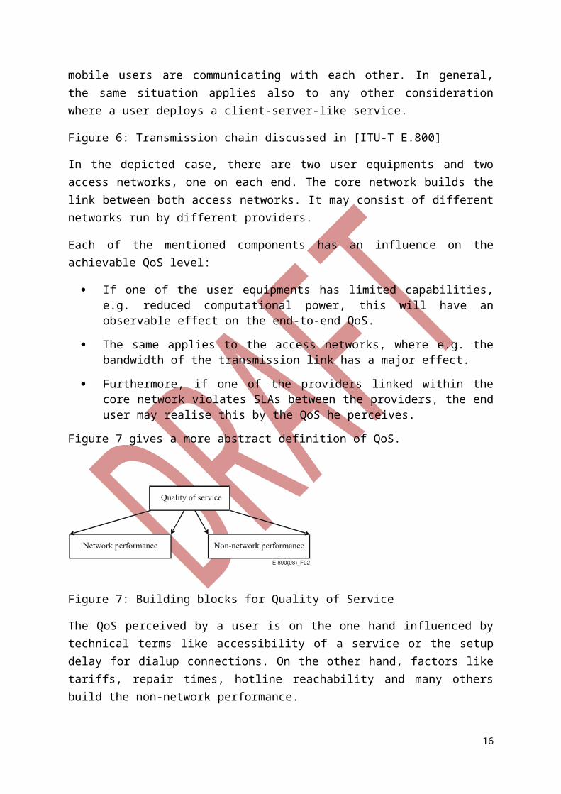
Figure 7 gives a more abstract definition of QoS.
Figure 7: Building blocks for Quality of Service
The QoS perceived by a user is on the one hand influenced by technical terms like accessibility of a service or the setup delay for dialup connections. On the other hand, factors like tariffs, repair times, hotline reachability and many others build the non-network performance.
Both components are integral parts of the end-to-end QoS perceived by the user.
6.2.3. PHASE ORIENTED ASPECT MODEL
The usage of a service can also be separated in different consecutive phases. Here, the order in time is the criterion which differentiates the states of the service usage.
Figure 8 shows the different phases of network access, service access and service usage and the according/relevant QoS aspects.
12
Network Availability
Network Access
Service Access
Service Usage
Start
Intentional End
Network Accessibility
Service Accessibility
Service Integrity
Service Retainability
Unintent-ional End (Cut-off)
End
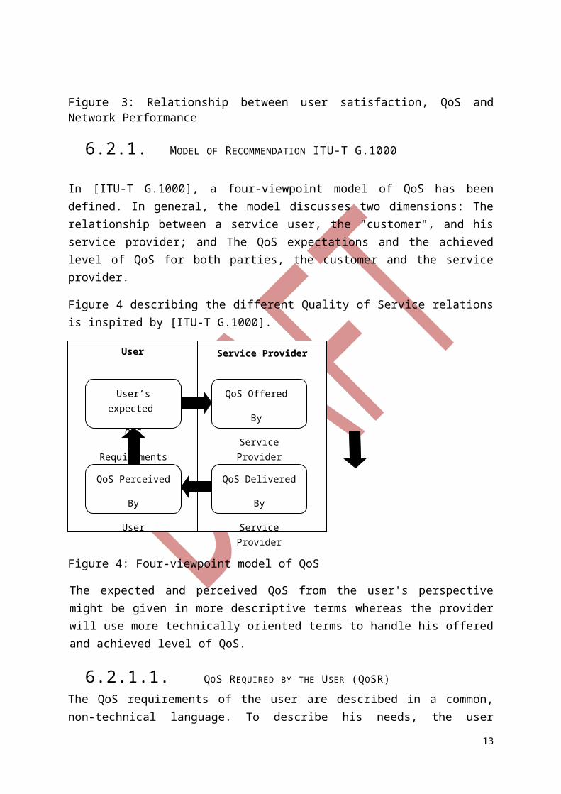
Figure 8: QoS aspects related to different phases of service usage [ITU-T E.804]
The meaning of these phase related QoS aspects is:
1) Network Availability: Probability that the services are offered to a user via a network infrastructure.
2) Network Accessibility: Probability that the user performs a successful registration on the network which delivers the service. The network can only be accessed if it is available to the user.
3) Service Accessibility: Probability that the user can access the service he wants to use. A given Network Accessibility is a precondition for this phase.
4) Service Integrity: This describes the Quality of Service during service use and contains elements like the quality of the transmitted content, e.g. speech quality, video quality or number of bit errors in a transmitted file. The Service Integrity can only be determined if the service has been accessed successfully.
5) Service Retainability: Service retainability describes the termination of services (in accordance with or against the will of the user). Examples for this are all kinds of cut-off parameters, e.g. the call cut-off ratio or the data cut-off ratio. Again, a previously performed successful service access is a precondition for this phase.
7. QUALITY OF SERVICE PARAMETERS
7.1. MOBILE NETWORKS
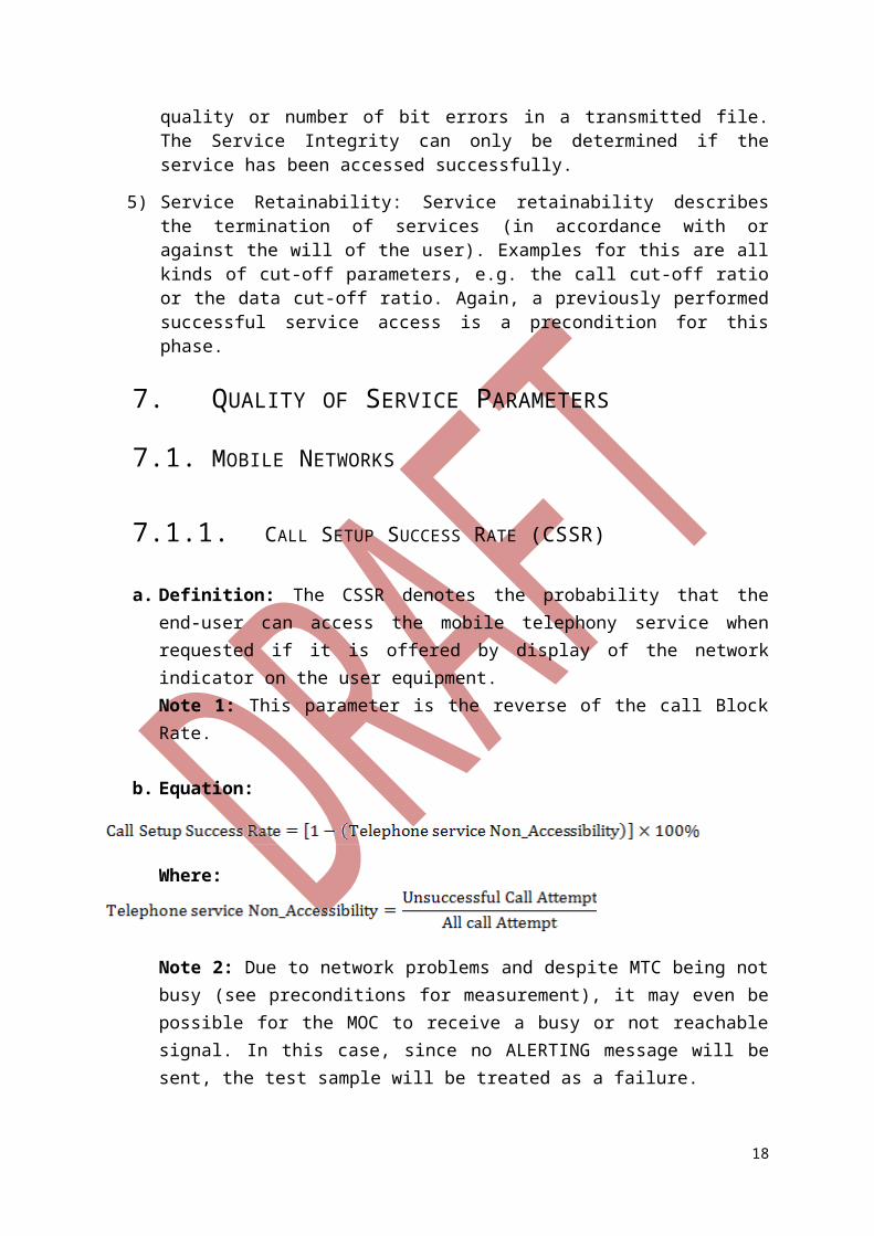
7.1.1. CALL SETUP SUCCESS RATE (CSSR)
a. Definition: The CSSR denotes the probability that the end-user can access the mobile telephony service when requested if it is offered by display of the network indicator on the user equipment. Note 1: This parameter is the reverse of the call Block Rate.
b. Equation:
Where:
Note 2: Due to network problems and despite MTC being not busy (see preconditions for measurement), it may even be possible for the MOC to receive a busy or not reachable signal. In this case, since no ALERTING message will be sent, the test sample will be treated as a failure.
13
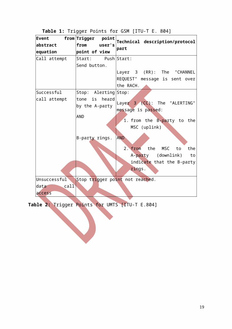
Table 1: Trigger Points for GSM [ITU-T E. 804]Event from abstract equation
Trigger point from user's point of view Technical description/protocol part
Call attempt Start: Push Send button.
Start:
Layer 3 (RR): The "CHANNEL REQUEST" message is sent over the RACH.
Successful call attempt
Stop: Alerting tone is heard by the A-party
AND
B-party rings.
Stop:
Layer 3 (CC): The "ALERTING" message is passed:
1. from the B-party to the MSC (uplink)
AND
2. from the MSC to the A-party (downlink) to indicate that the B-party rings.
Unsuccessful data call access
Stop trigger point not reached.
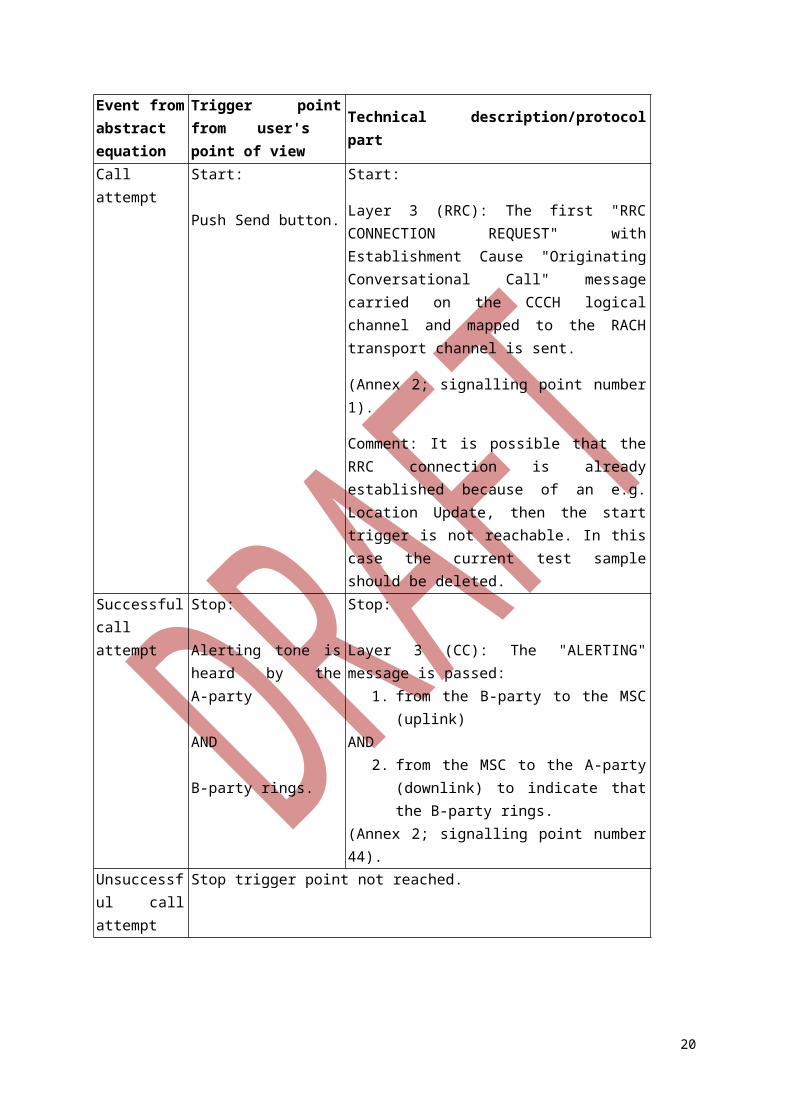
Table 2: Trigger Points for UMTS [ITU-T E.804]
14
Event from abstract equation
Trigger point from user's point of view
Technical description/protocol part
Call attempt Start:
Push Send button.
Start:
Layer 3 (RRC): The first "RRC CONNECTION REQUEST" with Establishment Cause "Originating Conversational Call" message carried on the CCCH logical channel and mapped to the RACH transport channel is sent.
(Annex 2; signalling point number 1).
Comment: It is possible that the RRC connection is already established because of an e.g. Location Update, then the start trigger is not reachable. In this case the current test sample should be deleted.
Successful call attempt
Stop:
Alerting tone is heard by theA-party
AND
B-party rings.
Stop:
Layer 3 (CC): The "ALERTING" message is passed:
1. from the B-party to the MSC (uplink) AND
2. from the MSC to the A-party (downlink) to indicate that the B-party rings.
(Annex 2; signalling point number 44).Unsuccessful call attempt
Stop trigger point not reached.
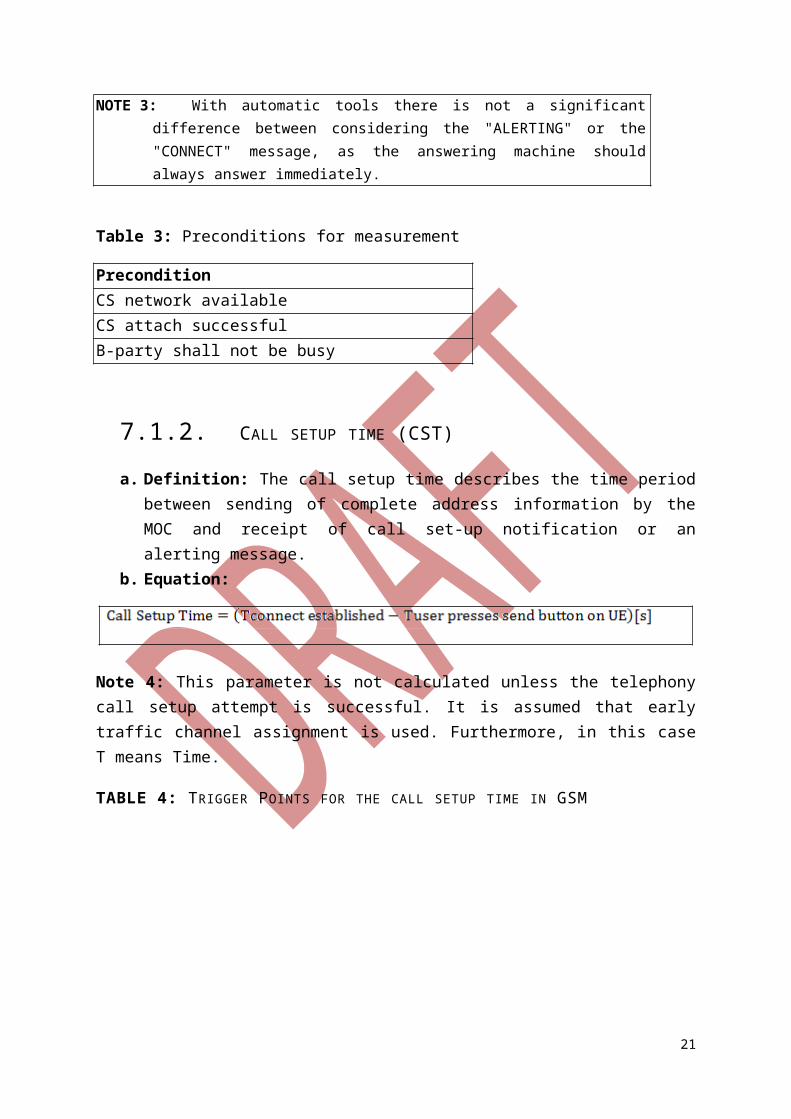
NOTE 3: With automatic tools there is not a significant difference between considering the "ALERTING" or the "CONNECT" message, as the answering machine should always answer immediately.
Table 3: Preconditions for measurement
PreconditionCS network availableCS attach successfulB-party shall not be busy
7.1.2. CALL SETUP TIME (CST)
a. Definition: The call setup time describes the time period between sending of complete address information by the MOC and receipt of call set-up notification or an alerting message.
b. Equation:
15
Note 4: This parameter is not calculated unless the telephony call setup attempt is successful. It is assumed that early traffic channel assignment is used. Furthermore, in this case T means Time.
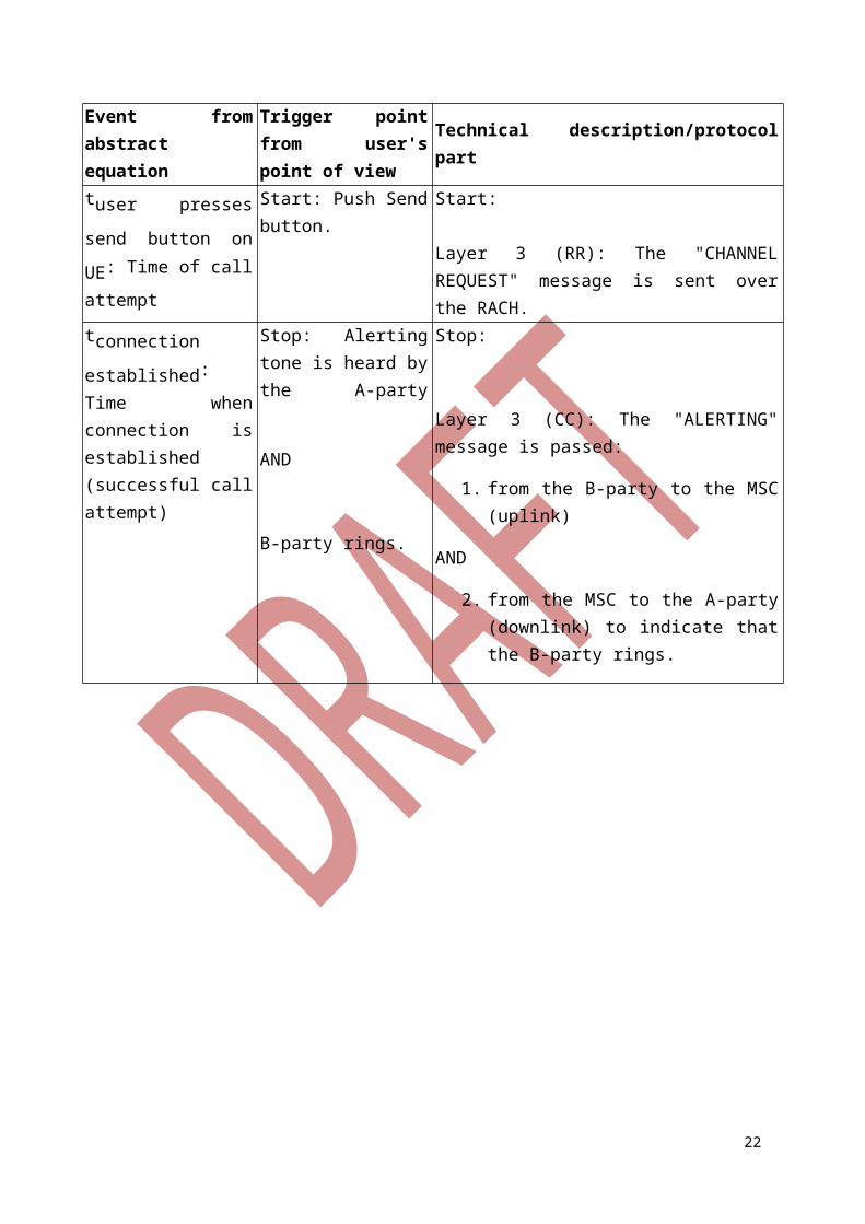
TABLE 4: TRIGGER POINTS FOR THE CALL SETUP TIME IN GSM
Event from abstract equation
Trigger point from user's point of view
Technical description/protocol part
tuser presses send
button on UE: Time of
call attempt
Start: Push Send button.
Start:
Layer 3 (RR): The "CHANNEL REQUEST" message is sent over the RACH.
tconnection
established: Time when
connection is established (successful call attempt)
Stop: Alerting tone is heard by the A-party
AND
B-party rings.
Stop:
Layer 3 (CC): The "ALERTING" message is passed:
1. from the B-party to the MSC (uplink)
AND
2. from the MSC to the A-party (downlink) to indicate that the B-party rings.
16
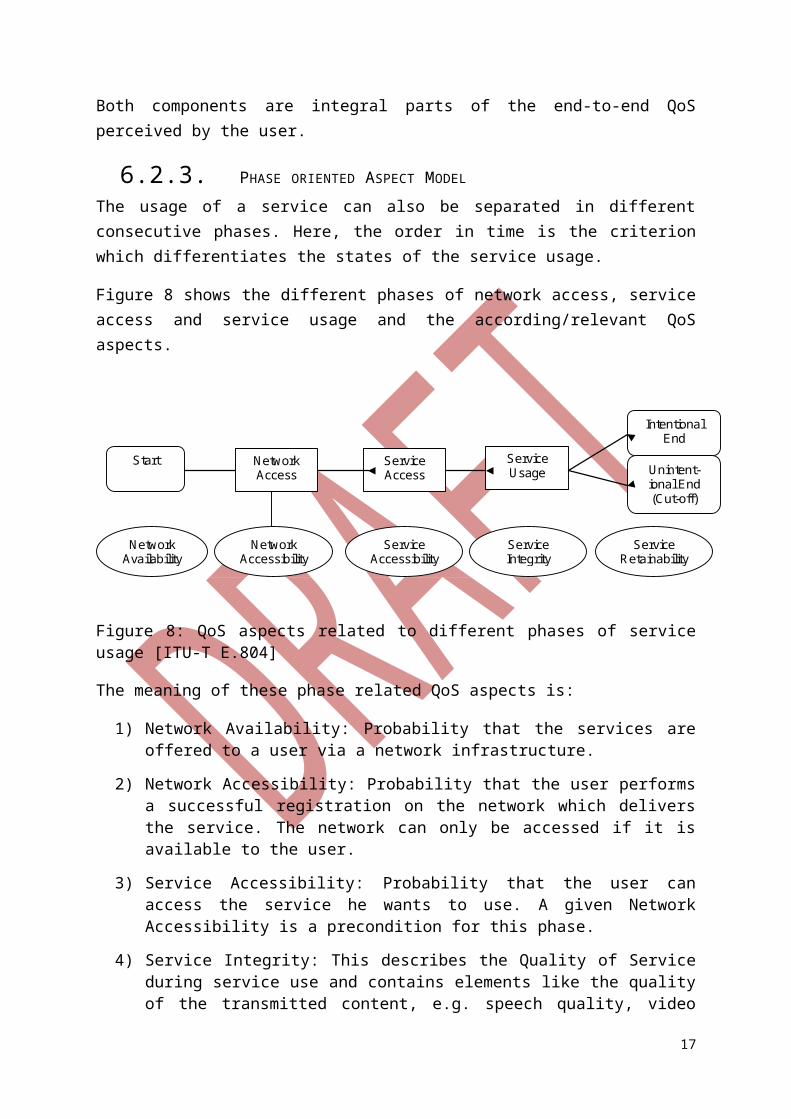
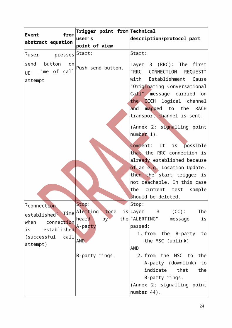
TABLE 5: TRIGGER POINTS FOR THE CALL SETUP TIME IN UMTS
Event from abstract equation
Trigger point from user's point of view
Technical description/protocol part
tuser presses send button
on UE: Time of call
attempt
Start:
Push send button.
Start:
Layer 3 (RRC): The first "RRC CONNECTION REQUEST" with Establishment Cause "Originating Conversational Call" message carried on the CCCH logical channel and mapped to the RACH transport channel is sent.
(Annex 2; signalling point number 1).
Comment: It is possible that the RRC connection is already established because of an e.g. Location Update, then the start trigger is not reachable. In this case the current test sample should be deleted.
tconnection established:
Time when connection is established (successful call attempt)
Stop: Alerting tone is heard by the A-party
AND
B-party rings.
Stop: Layer 3 (CC): The "ALERTING" message is passed:
1. from the B-party to the MSC (uplink)
AND2. from the MSC to the A-party
(downlink) to indicate that the B-party rings.
(Annex 2; signalling point number 44).
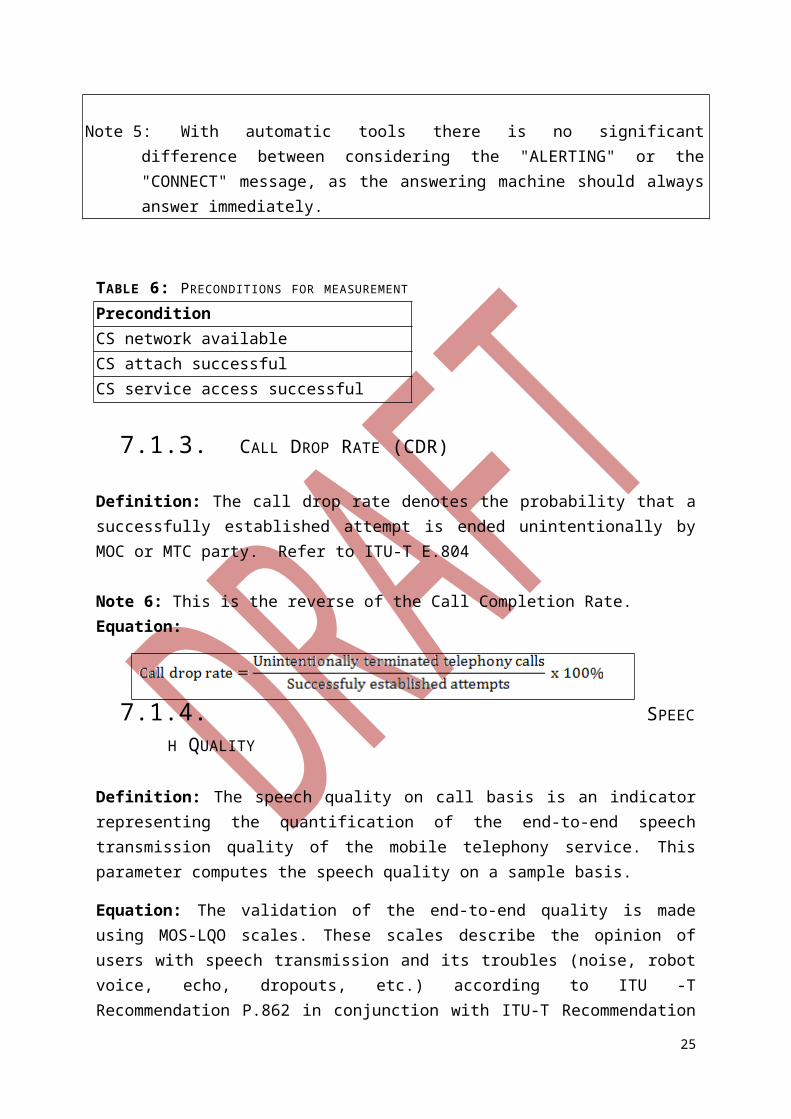
Note 5: With automatic tools there is no significant difference between considering the "ALERTING" or the "CONNECT" message, as the answering machine should always answer immediately.
TABLE 6: PRECONDITIONS FOR MEASUREMENT
PreconditionCS network availableCS attach successfulCS service access successful
17
7.1.3. CALL DROP RATE (CDR)
Definition: The call drop rate denotes the probability that a successfully established attempt is ended unintentionally by MOC or MTC party. Refer to ITU-T E.804
Note 6: This is the reverse of the Call Completion Rate.Equation:
7.1.4. SPEECH QUALITY
Definition: The speech quality on call basis is an indicator representing the quantification of the end-to-end speech transmission quality of the mobile telephony service. This parameter computes the speech quality on a sample basis.
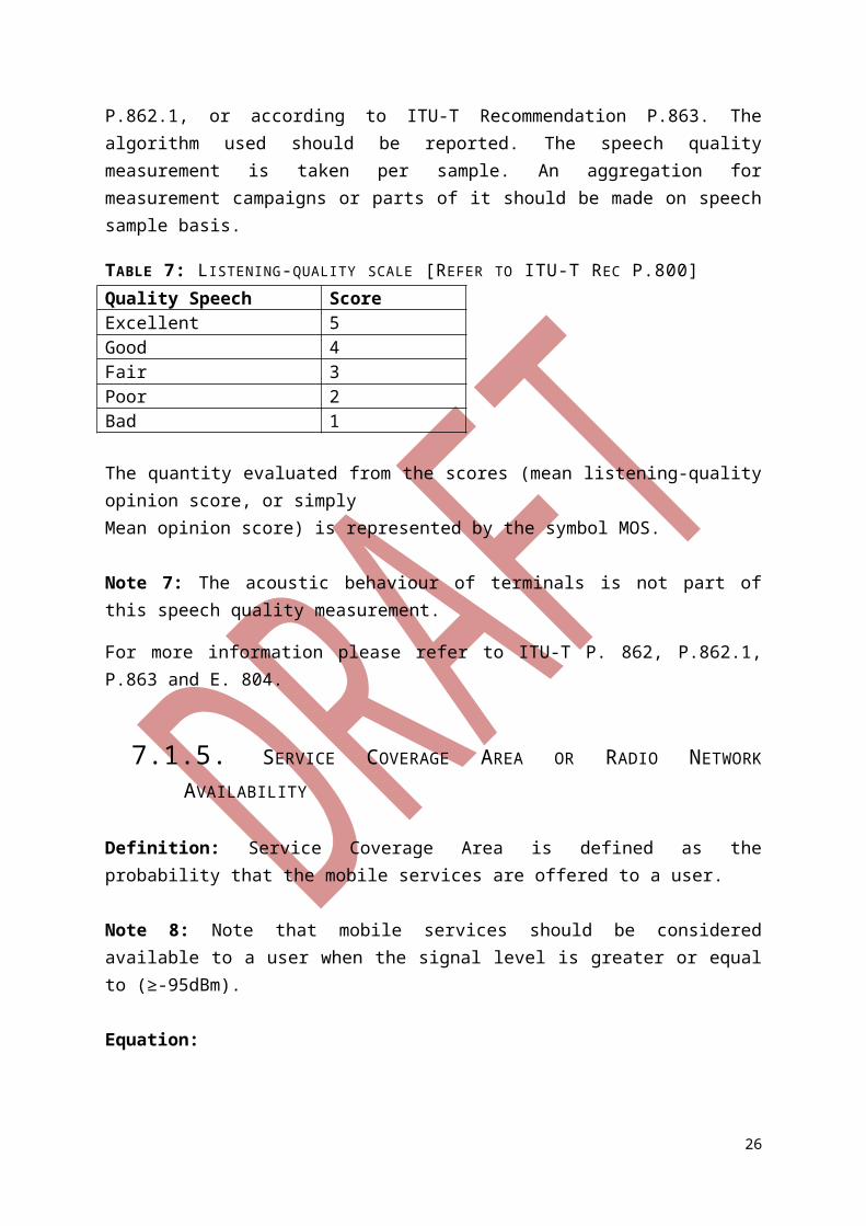
Equation: The validation of the end-to-end quality is made using MOS-LQO scales. These scales describe the opinion of users with speech transmission and its troubles (noise, robot voice, echo, dropouts, etc.) according to ITU -T Recommendation P.862 in conjunction with ITU-T Recommendation P.862.1, or according to ITU-T Recommendation P.863. The algorithm used should be reported. The speech quality measurement is taken per sample. An aggregation for measurement campaigns or parts of it should be made on speech sample basis.
TABLE 7: LISTENING-QUALITY SCALE [REFER TO ITU-T REC P.800]Quality Speech ScoreExcellent 5Good 4Fair 3Poor 2Bad 1
The quantity evaluated from the scores (mean listening-quality opinion score, or simplyMean opinion score) is represented by the symbol MOS.
Note 7: The acoustic behaviour of terminals is not part of this speech quality measurement.
For more information please refer to ITU-T P. 862, P.862.1, P.863 and E. 804.
7.1.5. SERVICE COVERAGE AREA OR RADIO NETWORK AVAILABILITY
18
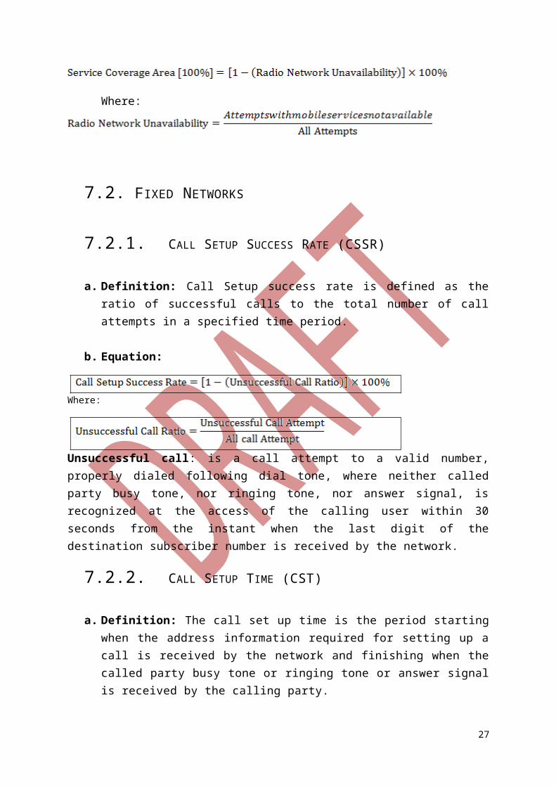
Definition: Service Coverage Area is defined as the probability that the mobile services are offered to a user.
Note 8: Note that mobile services should be considered available to a user when the signal level is greater or equal to (≥-95dBm).
Equation:
Where:
7.2. FIXED NETWORKS
7.2.1. CALL SETUP SUCCESS RATE (CSSR)
a. Definition: Call Setup success rate is defined as the ratio of successful calls to the total number of call attempts in a specified time period.
b. Equation:
Where:
Unsuccessful call: is a call attempt to a valid number, properly dialed following dial tone, where neither called party busy tone, nor ringing tone, nor answer signal, is recognized at the access of the calling user within 30 seconds from the instant when the last digit of the destination subscriber number is received by the network.
7.2.2. CALL SETUP TIME (CST)
a. Definition: The call set up time is the period starting when the address information required for setting up a call is received by the network and finishing when the called party busy tone or ringing tone or answer signal is received by the calling party.
b. Equation:
19
7.2.3. FAULT REPAIR TIME (FRT)
a. Definition:
The duration from the instant a fault report has been made to the instant when the service element or service has been restored to normal working order.
b. Equation: The percentage of faults cleared in a period ≤ 8Hrs to all faults. In this case the time should be reported together with the percentage.
Note 8: Measurements and statistics of the voice service in fixed networks, please [refer to ETSI EG 202 057-2 V1.3.2 (2011-04)]
8. HARMONIZATION
This section aims at proposing a common and standardized approach in terms of definition of parameters. This section aims at proposing parameters and their thresholds where applicable. This is summarized in the table below.
Note 9: This list of parameters is not exhaustive but has generally identified the parameters that directly impacts the users experience and can be empirically resolved by the operators. Resolution of the targets for the identified parameters will provide a general resolution of the other concerns for customer satisfaction.
Table 8: QoS Parameters and related threshold for the voice call in Mobile Networks
S/N QoS Parameters Threshold
1. Call Setup Success Rate (CSSR) ≥95 %
2. Call set up time (CST) ≤ 9 secs in ≥ 98% of the cases
3.Call Drop Rate (CDR) ≤2%
4. Speech Quality For ≥95% of samples ≥3 using MOS, PESQ or
20
POLQA algorithms
5. Service coverage Area (Out-door signal level)
≥ -95 dBm
Note10: The percentage of coverage to be set as threshold should depend on Operator Business plan.
Table 9: QoS Parameters and related threshold for the voice call in Fixed Networks
S/N QoS Parameters Threshold
1. Call setup success rate 95%
2. Call set up time ≤ 9 seconds, for ≥ 98 % of the cases
3. Fault repair time ≥ 95%
21
ANNEX 1: MEASUREMENT POINTS IN MOBILE ORIGINATING CALL (MOC) CALL SET-UP PROCEDURE IN GSM [REF: ITU-T E.807]
BTS 1 BSC 1 Channel Request
Channel Required
Channel Active Channel Active
ACK Immediate Assignment Command
SABM UA Established
Indication CR CC
CM Service Accepted Setup
Call Proceeding Assignment
Request Channel Active Channel Active
ACK Assignment Command
SABM UA
Established Indication
Assignment Complete Assignment
Complete
A1
A2
MS 1
Alerting
MSC
Release
UL Disconnect
Connect
Release Complete
Clear Command
Channel Release
Connect Acknowledge
B1
B2
22

23
ANNEX 2: 3G TELEPHONY SIGNALLING FLOW CHART: MOBILE ORIGINATED CALL (MOC) ESTABLISHMENT PROCEDURE [REF: ITU-T E.804]
24
UE Node B RNC MSC / VLR MGW
RRC1. RACH: CCCH: RRC CONNECTION REQUEST <TM>
2. RADIO LINK SETUP REQUEST
3. RADIO LINK SETUP RESPONSE
6. DOWNLINK SYNCHRONISATION
7. UPLINK SYNCHRONISATION
11. DCCH: RRC CONNECTION SETUP COMPLETE <AM>
8. FACH: CCCH: RRC CONNECTION SETUP <UM>
4. ESTABLISH REQUEST (AAL2)
5. ESTABLISH CONFIRM (AAL2)
Start RX
RRC
NBAPNBAP
NBAPNBAP
ALCAP
ALCAP
ALCAP
ALCAP
DCH-FPDCH-FP
DCH-FP DCH-FP
RRC
RRC
RRC
RRC
Start TX
10. RADIO LINK RESTORE INDICATIONNBAPNBAP
9. INSYNCH INDL1 L1
25
UE Node B RNC MSC / VLR MGW
18. DCCH: SECURITY MODE COMPLETE <AM>
16. SECURITY MODE COMMAND
17. DCCH: SECURITY MODE COMMAND <AM>
19. SECURITY MODE COMPLETE
RRC
RRC
RRC
RRC
RANAPRANAP
RANAPRANAP
24. DCCH: ULDT [ SETUP ] <AM>
25. DT [ SETUP ]
27. DT [ CALL PROCEEDING ]
28. DCCH: DLDT [ CALL PROCEEDING ] <AM>
RANAP RANAP
RANAPRANAP
RRC
RRCRRC
RRC
22. DCCH: ULDT [ IDENTITY RESPONSE ] <AM> (IMEI)
20. DT [ IDENTITY REQUEST ] (IMEI)
21. DCCH: DLDT [ IDENTITY REQUEST ] <AM> (IMEI)
23. DT [ IDENTITY RESPONSE ] (IMEI)
RRC
RRC
RRC
RRC
RANAPRANAP
RANAPRANAP
26. INITIAL DP
12. DCCH: INITIAL DT [ CM SERVICE REQUEST ] <AM>13. SCCP CONNECTION RQ [
INITIAL UE MESSAGE[ CM SERVICE REQUEST ] ]
RRCRRC
14. SCCP CONNECTIONCONFIRM
SCCP SCCP
15. COMMON IDRANAP RANAP
SCCP SCCP
26
UE Node B RNC MSC / VLR MGW
39. RAB ASSIGNMENT RESPONSE
41. IAM
RANAP RANAP
ISUP
49. DCCH: ULDT [ CONNECT ACK ] <AM>
43. DT [ ALERTING ]
44. DCCH: DLDT [ ALERTING ] <AM>
50. DT [ CONNECT ACK ]
46. DT [ CONNECT ]
47. DCCH: DLDT [ CONNECT ] <AM>
42. ACM
45. ANS
RANAP RANAP
RANAPRANAP
RANAP RANAP
RRC ISUP
ISUP
RRC
RRCRRC
RRC RRC
31. ESTABLISH REQUEST ( AAL2 )
32. ESTABLISH CONFIRM ( AAL2 )
ALCAP
ALCAP ALCAP
ALCAP
38. DCCH: RADIO BEARER SETUP <AM>
40. DCCH: RADIO BEARER SETUP COMPLETE <AM>
RRC
RRCRRC
RRC
35. ESTABLISH REQUEST (AAL2)
36. ESTABLISH CONFIRM (AAL2)
ALCAP
ALCAP
ALCAP
ALCAP
33. RADIO LINK RECONFIG PREPARE
34. RADIO LINK RECONFIG READY
NBAPNBAP
NBAPNBAP
48. OPENCONNECTION
30. RAB ASSIGNMENT REQUESTRANAP RANAP
29. BINDING ID, SPEECHCODEC TYPE, B PARTY
ROUTE
37. RADIO LINK RECONFIG COMMITNBAPNBAP
27