Embed Size (px)
Citation preview
INTRO.AP1INTRODUCTION
The following Amendments and Special Provisions shall be used in conjunction with the 2018 Standard Specifications for Road, Bridge, and Municipal Construction.
AMENDMENTS TO THE STANDARD SPECIFICATIONS
The following Amendments to the Standard Specifications are made a part of this contract and supersede any conflicting provisions of the Standard Specifications. For informational purposes, the date following each Amendment title indicates the implementation date of the Amendment or the latest date of revision.
Each Amendment contains all current revisions to the applicable section of the Standard Specifications and may include references which do not apply to this particular project.
1-01.AP1Section 1-01, Definitions and TermsAugust 6, 2018
1-01.3 DefinitionsThe following new term and definition is inserted before the definition for “Shoulder”:
Sensitive Area – Natural features, which may be previously altered by human activity, that are present on or adjacent to the project location and protected, managed, or regulated by local, tribal, state, or federal agencies.
The following new term and definition is inserted after the definition for “Working Drawings”:
WSDOT Form – Forms developed and maintained by WSDOT that are required or available for use on a project. These forms can be downloaded from the forms catalogue at:
http://wsdot.wa.gov/forms/pdfForms.html
1-02.AP1Section 1-02, Bid Procedures and ConditionsOctober 30, 2018
1-02.4(1) GeneralThis section is supplemented with the following:
Prospective Bidders are advised that the Contracting Agency may include a partially completed Washington State Department of Ecology (Ecology) Transfer of Coverage (Ecology Form ECY 020-87a) for the Construction Stormwater General Permit (CSWGP) as part of the Bid Documents. When the Contracting Agency requires the transfer of coverage of the CSWGP to the Contractor, an informational copy of the Transfer of Coverage and the associated CSWGP will be included in the appendices. As a condition of Section 1-03.3, the Contractor is required to complete sections I, III, and VIII of the Transfer of Coverage and return the form to the Contracting Agency.
AMENDMENTS TO THE 2018 STANDARD SPECIFICATIONS BOOKRevised: 4/1/19
12
3456789
101112131415161718
192021222324252627282930313233343536
373839404142434445464748

The Contracting Agency is responsible for compliance with the CSWGP until the end of day that the Contract is executed. Beginning on the day after the Contract is executed, the Contractor shall assume complete legal responsibility for compliance with the CSWGP and full implementation of all conditions of the CSWGP as they apply to the Contract Work.
1-02.5 Proposal FormsThe first sentence of the first paragraph is revised to read:
At the request of a Bidder, the Contracting Agency will provide a physical Proposal Form for any project on which the Bidder is eligible to Bid.
1-02.6 Preparation of ProposalItem number 1 of the second paragraph is revised to read:
1. A unit price for each item (omitting digits more than two places to the right of the decimal point),
In the third sentence of the fourth paragraph, “WSDOT Form 422-031” is revised to read “WSDOT Form 422-031U”.
The following new paragraph is inserted before the last paragraph:
The Bidder shall submit with their Bid a completed Contractor Certification Wage Law Compliance form (WSDOT Form 272-009). Failure to return this certification as part of the Bid Proposal package will make this Bid Nonresponsive and ineligible for Award. A Contractor Certification of Wage Law Compliance form is included in the Proposal Forms.
1-03.AP1Section 1-03, Award and Execution of ContractJanuary 2, 2018
1-03.3 Execution of ContractThe first paragraph is revised to read:
Within 20 calendar days after the Award date, the successful Bidder shall return the signed Contracting Agency-prepared Contract, an insurance certification as required by Section 1-07.18, a satisfactory bond as required by law and Section 1-03.4, the Transfer of Coverage form for the Construction Stormwater General Permit with sections I, III, and VIII completed when provided, and shall be registered as a contractor in the state of Washington.
1-03.5 Failure to Execute ContractThe first sentence is revised to read:
Failure to return the insurance certification and bond with the signed Contract as required in Section 1-03.3, or failure to provide Disadvantaged, Minority or Women’s Business Enterprise information if required in the Contract, or failure or refusal to sign the Contract, or failure to register as a contractor in the state of Washington, or failure to return the completed Transfer of Coverage for the Construction Stormwater General
AMENDMENTS TO THE 2018 STANDARD SPECIFICATIONS BOOKRevised: 4/1/19
123456789
101112131415161718192021222324252627282930313233
343536373839404142434445464748495051
Permit to the Contracting Agency when provided shall result in forfeiture of the proposal bond or deposit of this Bidder.
1-05.AP1Section 1-05, Control of WorkAugust 6, 2018
1-05.5 VacantThis section, including title, is revised to read:
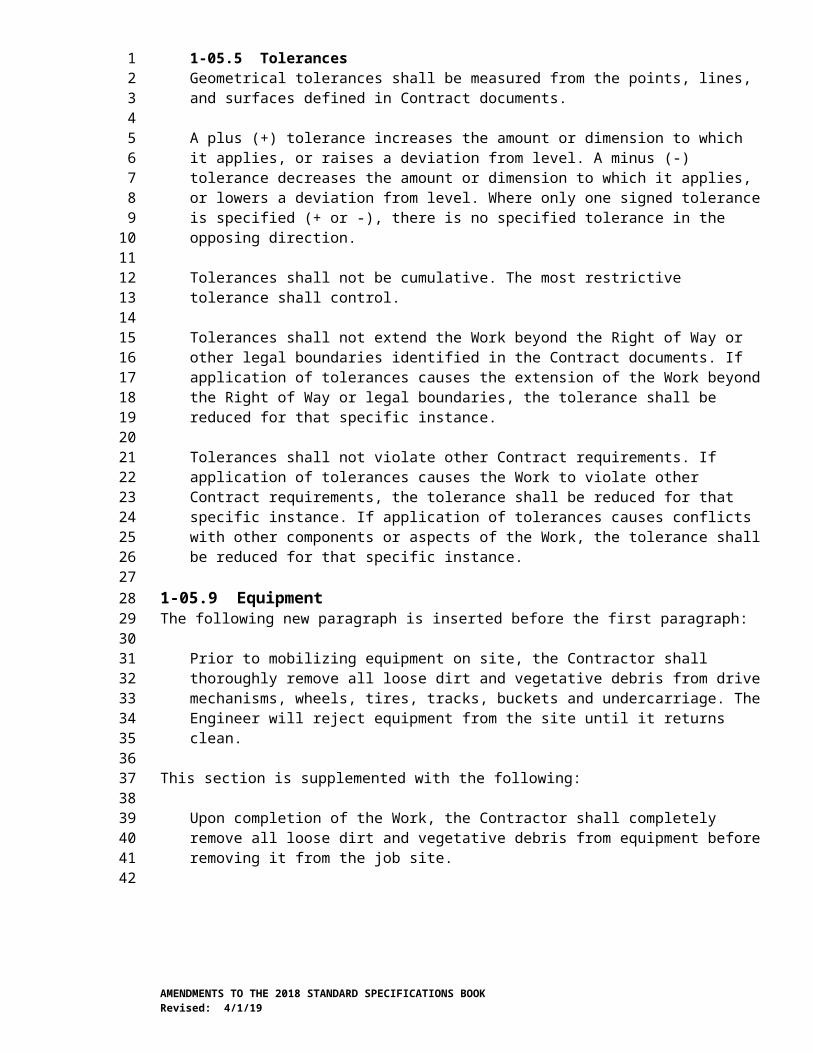
1-05.5 TolerancesGeometrical tolerances shall be measured from the points, lines, and surfaces defined in Contract documents.
A plus (+) tolerance increases the amount or dimension to which it applies, or raises a deviation from level. A minus (-) tolerance decreases the amount or dimension to which it applies, or lowers a deviation from level. Where only one signed tolerance is specified (+ or -), there is no specified tolerance in the opposing direction.
Tolerances shall not be cumulative. The most restrictive tolerance shall control.
Tolerances shall not extend the Work beyond the Right of Way or other legal boundaries identified in the Contract documents. If application of tolerances causes the extension of the Work beyond the Right of Way or legal boundaries, the tolerance shall be reduced for that specific instance.
Tolerances shall not violate other Contract requirements. If application of tolerances causes the Work to violate other Contract requirements, the tolerance shall be reduced for that specific instance. If application of tolerances causes conflicts with other components or aspects of the Work, the tolerance shall be reduced for that specific instance.
1-05.9 EquipmentThe following new paragraph is inserted before the first paragraph:
Prior to mobilizing equipment on site, the Contractor shall thoroughly remove all loose dirt and vegetative debris from drive mechanisms, wheels, tires, tracks, buckets and undercarriage. The Engineer will reject equipment from the site until it returns clean.
This section is supplemented with the following:
Upon completion of the Work, the Contractor shall completely remove all loose dirt and vegetative debris from equipment before removing it from the job site.
1-06.AP1Section 1-06, Control of MaterialJanuary 7, 2019
1-06.1(3) Aggregate Source Approval (ASA) DatabaseThis section is supplemented with the following:
AMENDMENTS TO THE 2018 STANDARD SPECIFICATIONS BOOKRevised: 4/1/19
123456
789
10111213141516171819202122232425262728293031323334353637383940414243444546
474849
Regardless of status of the source, whether listed or not listed in the ASA database the source owner may be asked to provide testing results for toxicity in accordance with Section 9-03.21(1).
1-06.2(2)D Quality Level AnalysisThis section is supplemented with the following new subsection:
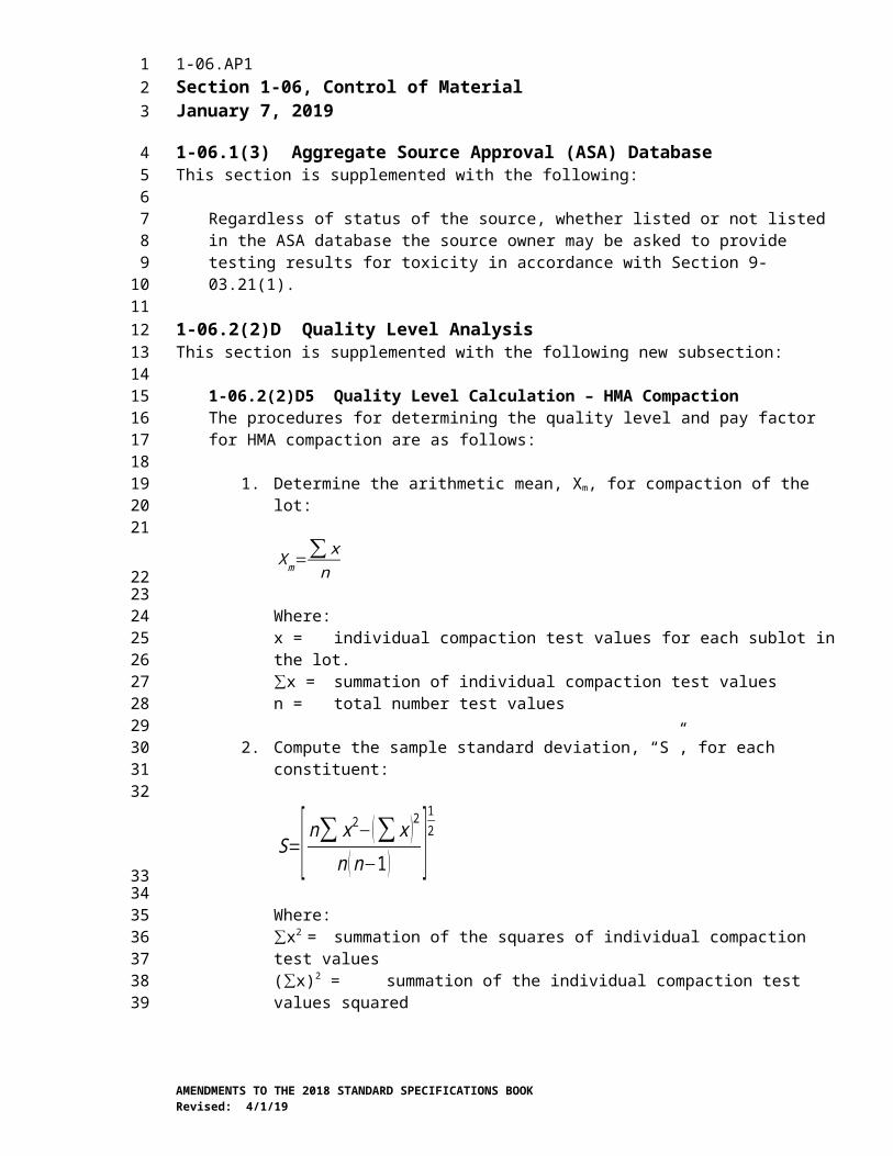
1-06.2(2)D5 Quality Level Calculation – HMA CompactionThe procedures for determining the quality level and pay factor for HMA compaction are as follows:
1. Determine the arithmetic mean, Xm, for compaction of the lot:
X m=∑ xn
Where:x = individual compaction test values for each sublot in the lot.∑x = summation of individual compaction test valuesn = total number test values
2. Compute the sample standard deviation, “S”, for each constituent:
S=[ n∑ x2−(∑ x )2
n (n−1 ) ]12
Where:∑x2 = summation of the squares of individual compaction test values(∑x)2 = summation of the individual compaction test values squared
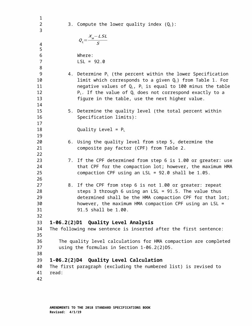
3. Compute the lower quality index (QL):
QL=Xm−LSL
S
Where:LSL = 92.0
4. Determine PL (the percent within the lower Specification limit which corresponds to a given QL) from Table 1. For negative values of QL, PL is equal to 100 minus the table PL. If the value of QL does not correspond exactly to a figure in the table, use the next higher value.
5. Determine the quality level (the total percent within Specification limits):
Quality Level = PL
6. Using the quality level from step 5, determine the composite pay factor (CPF) from Table 2.
AMENDMENTS TO THE 2018 STANDARD SPECIFICATIONS BOOKRevised: 4/1/19
123456789
10111213
141516171819202122
2324252627282930
31323334353637383940414243444546
7. If the CPF determined from step 6 is 1.00 or greater: use that CPF for the compaction lot; however, the maximum HMA compaction CPF using an LSL = 92.0 shall be 1.05.
8. If the CPF from step 6 is not 1.00 or greater: repeat steps 3 through 6 using an LSL = 91.5. The value thus determined shall be the HMA compaction CPF for that lot; however, the maximum HMA compaction CPF using an LSL = 91.5 shall be 1.00.
1-06.2(2)D1 Quality Level AnalysisThe following new sentence is inserted after the first sentence:
The quality level calculations for HMA compaction are completed using the formulas in Section 1-06.2(2)D5.
1-06.2(2)D4 Quality Level CalculationThe first paragraph (excluding the numbered list) is revised to read:
The procedures for determining the quality level and pay factors for a material, other than HMA compaction, are as follows:
1-06.6 Recycled MaterialsThe first three sentences of the second paragraph are revised to read:
The Contractor shall submit a Recycled Material Utilization Plan on WSDOT Form 350-075A within 30 calendar days after the Contract is executed. The plan shall provide the Contractor’s anticipated usage of recycled concrete aggregates for meeting the requirements of these Specifications. The quantity of recycled concrete aggregate will be provided in tons and as a percentage of the Plan quantity for eligible material listed in Section 9-03.21(1)E Table on Maximum Allowable percent (By Weight) of Recycled Material.
The last paragraph is revised to read:
Within 30 calendar days after Physical Completion, the Contractor shall report the quantity of recycled concrete aggregates that were utilized in the construction of the project for each eligible item listed in Section 9-03.21(1)E. The Contractor’s report shall be provided on WSDOT Form 350-075A, Recycled Materials Reporting.
1-06.6(1)A GeneralItem 1(a) in the second paragraph is revised to read:
a. The estimated costs for the Work for each material with 25 percent recycled concrete aggregate. The cost estimate shall include for each material a documented price quote from the supplier with the lowest total cost for the Work.
AMENDMENTS TO THE 2018 STANDARD SPECIFICATIONS BOOKRevised: 4/1/19
123456789
1011121314151617181920212223242526272829303132333435363738394041424344454647
1-07.AP1Section 1-07, Legal Relations and Responsibilities to the PublicApril 1, 2019
1-07.5 Environmental RegulationsThis section is supplemented with the following new subsections:
1-07.5(5) U.S. Army Corps of EngineersWhen temporary fills are permitted, the Contractor shall remove fills in their entirety and the affected areas returned to pre-construction elevations.
If a U.S. Army Corps of Engineers permit is noted in Section 1-07.6 of the Special Provisions, the Contractor shall retain a copy of the permit or the verification letter (in the case of a Nationwide Permit) on the worksite for the life of the Contract. The Contractor shall provide copies of the permit or verification letter to all subcontractors involved with the authorized work prior to their commencement of any work in waters of the U.S.
1-07.5(6) U.S. Fish/Wildlife Services and National Marine Fisheries ServiceThe Contracting Agency will provide fish exclusion and handling services if the Work dictates. However, if the Contractor discovers any fish stranded by the project and a Contracting Agency biologist is not available, they shall immediately release the fish into a flowing stream or open water.
1-07.5(1) GeneralThe first sentence is deleted and replaced with the following:
No Work shall occur within areas under the jurisdiction of resource agencies unless authorized in the Contract.
The third paragraph is deleted.
1-07.5(2) State Department of Fish and WildlifeThis section is revised to read:
In doing the Work, the Contractor shall:
1. Not degrade water in a way that would harm fish, wildlife, or their habitat.
2. Not place materials below or remove them from the ordinary high water line except as may be specified in the Contract.
3. Not allow equipment to enter waters of the State except as specified in the Contract.
4. Revegetate in accordance with the Plans, unless the Special Provisions permit otherwise.
5. Prevent any fish-threatening silt buildup on the bed or bottom of any body of water.
6. Ensure continuous stream flow downstream of the Work area.
AMENDMENTS TO THE 2018 STANDARD SPECIFICATIONS BOOKRevised: 4/1/19
123
456789
101112131415161718192021222324252627282930313233343536373839404142434445464748495051
7. Dispose of any project debris by removal, burning, or placement above high-water flows.
8. Immediately notify the Engineer and stop all work causing impacts, if at any time, as a result of project activities, fish are observed in distress or a fish kill occurs.
If the Work in (1) through (3) above differs little from what the Contract requires, the Contracting Agency will measure and pay for it at unit Contract prices. But if Contract items do not cover those areas, the Contracting Agency will pay pursuant to Section 1-09.4. Work in (4) through (8) above shall be incidental to Contract pay items.
1-07.5(3) State Department of EcologyThis section is revised to read:
In doing the Work, the Contractor shall:
1. Comply with Washington State Water Quality Standards.
2. Perform Work in such a manner that all materials and substances not specifically identified in the Contract documents to be placed in the water do not enter waters of the State, including wetlands. These include, but are not limited to, petroleum products, hydraulic fluid, fresh concrete, concrete wastewater, process wastewater, slurry materials and waste from shaft drilling, sediments, sediment-laden water, chemicals, paint, solvents, or other toxic or deleterious materials.
3. Use equipment that is free of external petroleum-based products.
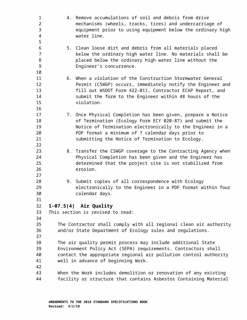
4. Remove accumulations of soil and debris from drive mechanisms (wheels, tracks, tires) and undercarriage of equipment prior to using equipment below the ordinary high water line.
5. Clean loose dirt and debris from all materials placed below the ordinary high water line. No materials shall be placed below the ordinary high water line without the Engineer’s concurrence.
6. When a violation of the Construction Stormwater General Permit (CSWGP) occurs, immediately notify the Engineer and fill out WSDOT Form 422-011, Contractor ECAP Report, and submit the form to the Engineer within 48 hours of the violation.
7. Once Physical Completion has been given, prepare a Notice of Termination (Ecology Form ECY 020-87) and submit the Notice of Termination electronically to the Engineer in a PDF format a minimum of 7 calendar days prior to submitting the Notice of Termination to Ecology.
8. Transfer the CSWGP coverage to the Contracting Agency when Physical Completion has been given and the Engineer has determined that the project site is not stabilized from erosion.
AMENDMENTS TO THE 2018 STANDARD SPECIFICATIONS BOOKRevised: 4/1/19
123456789
10111213141516171819202122232425262728293031323334353637383940414243444546474849505152
9. Submit copies of all correspondence with Ecology electronically to the Engineer in a PDF format within four calendar days.
1-07.5(4) Air QualityThis section is revised to read:
The Contractor shall comply with all regional clean air authority and/or State Department of Ecology rules and regulations.
The air quality permit process may include additional State Environment Policy Act (SEPA) requirements. Contractors shall contact the appropriate regional air pollution control authority well in advance of beginning Work.
When the Work includes demolition or renovation of any existing facility or structure that contains Asbestos Containing Material (ACM) and/or Presumed Asbestos-Containing Material (PACM), the Contractor shall comply with the National Emission Standards for Hazardous Air Pollutants (NESHAP).
Any requirements included in Federal and State regulations regarding air quality that applies to the “owner or operator” shall be the responsibility of the Contractor.
1-07.7(1) GeneralThe first sentence of the third paragraph is revised to read:
When the Contractor moves equipment or materials on or over Structures, culverts or pipes, the Contractor may operate equipment with only the load-limit restrictions in Section 1-07.7(2).
The first sentence of the last paragraph is revised to read:
Unit prices shall cover all costs for operating over Structures, culverts and pipes.
1-07.9(1) GeneralThe last sentence of the sixth paragraph is revised to read:
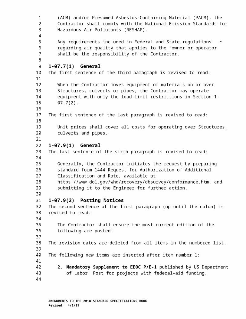
Generally, the Contractor initiates the request by preparing standard form 1444 Request for Authorization of Additional Classification and Rate, available at https://www.dol.gov/whd/recovery/dbsurvey/conformance.htm, and submitting it to the Engineer for further action.
1-07.9(2) Posting NoticesThe second sentence of the first paragraph (up until the colon) is revised to read:
The Contractor shall ensure the most current edition of the following are posted:
The revision dates are deleted from all items in the numbered list.
The following new items are inserted after item number 1:
2. Mandatory Supplement to EEOC P/E-1 published by US Department of Labor. Post for projects with federal-aid funding.
AMENDMENTS TO THE 2018 STANDARD SPECIFICATIONS BOOKRevised: 4/1/19
123456789
10111213141516171819202122232425262728293031323334353637383940414243444546474849505152
3. Pay Transparency Nondiscrimination Provision published by US Department of Labor. Post for projects with federal-aid funding.
Item number 2 through 12 are renumbered to 4 through 14, respectively.
1-07.11(2) Contractual RequirementsIn this section, “creed” is revised to read “religion”.
Item numbers 1 through 9 are revised to read 2 through 10, respectively.
After the preceding Amendment is applied, the following new item number 1 is inserted:
1. The Contractor shall maintain a Work site that is free of harassment, humiliation, fear, hostility and intimidation at all times. Behaviors that violate this requirement include but are not limited to:
a. Persistent conduct that is offensive and unwelcome.
b. Conduct that is considered to be hazing.
c. Jokes about race, gender, or sexuality that are offensive.
d. Unwelcome, unwanted, rude or offensive conduct or advances of a sexual nature which interferes with a person’s ability to perform their job or creates an intimidating, hostile, or offensive work environment.
e. Language or conduct that is offensive, threatening, intimidating or hostile based on race, gender, or sexual orientation.
f. Repeating rumors about individuals in the Work Site that are considered to be harassing or harmful to the individual’s reputation.
1-07.11(5) SanctionsThis section is supplemented with the following:
Immediately upon the Engineer’s request, the Contractor shall remove from the Work site any employee engaging in behaviors that promote harassment, humiliation, fear or intimidation including but not limited to those described in these specifications.
1-07.11(6) Incorporation of ProvisionsThe first sentence is revised to read:
The Contractor shall include the provisions of Section 1-07.11(2) Contractual Requirements (1) through (5) and the Section 1-07.11(5) Sanctions in every subcontract including procurement of materials and leases of equipment.
1-07.15(1) Spill Prevention, Control, and Countermeasures PlanThe last sentence of the first paragraph is revised to read:
An SPCC Plan template and guidance information is available at http://www.wsdot.wa.gov/environment/technical/disciplines/hazardous-materials/spill-prevent-report.
AMENDMENTS TO THE 2018 STANDARD SPECIFICATIONS BOOKRevised: 4/1/19
123456789
10111213141516171819202122232425262728293031323334353637383940414243444546474849505152
1-07.16(2)A Wetland and Sensitive Area ProtectionThe first sentence of the first paragraph is revised to read:
Existing wetland and other sensitive areas, where shown in the Plans or designated by the Engineer, shall be saved and protected through the life of the Contract.
1-07.18 Public Liability and Property Damage InsuranceItem number 1 is supplemented with the following new sentence:
This policy shall be kept in force from the execution date of the Contract until the Physical Completion Date.
1-08.AP1Section 1-08, Prosecution and ProgressJanuary 7, 2019
1-08.1 SubcontractingThe first sentence of the seventh paragraph is revised to read:
All Work that is not performed by the Contractor will be considered as subcontracting except: (1) purchase of sand, gravel, crushed stone, crushed slag, batched concrete aggregates, ready-mix concrete, off-site fabricated structural steel, other off-site fabricated items, and any other materials supplied by established and recognized commercial plants; or (2) delivery of these materials to the Work site in vehicles owned or operated by such plants or by recognized independent or commercial hauling companies hired by those commercial plants.
The following new paragraph is inserted after the seventh paragraph:
The Contractor shall not use businesses (material suppliers, vendors, subcontractors, etc.) with federal purchasing exclusions. Businesses with exclusions are identified using the System for Award Management web page at www.SAM.gov.
1-08.5 Time for CompletionItem number 2 of the sixth paragraph is supplemented with the following:
f. A copy of the Notice of Termination sent to the Washington State Department of Ecology (Ecology); the elapse of 30 calendar days from the date of receipt of the Notice of Termination by Ecology; and no rejection of the Notice of Termination by Ecology. This requirement will not apply if the Construction Stormwater General Permit is transferred back to the Contracting Agency in accordance with Section 8-01.3(16).
1-08.7 Maintenance During SuspensionThe fifth paragraph is revised to read:
The Contractor shall protect and maintain all other Work in areas not used by traffic. All costs associated with protecting and maintaining such Work shall be the responsibility of the Contractor.
AMENDMENTS TO THE 2018 STANDARD SPECIFICATIONS BOOKRevised: 4/1/19
123456789
101112131415
16171819202122232425262728293031323334353637383940414243444546474849
1-09.AP1Section 1-09, Measurement and PaymentAugust 6, 2018
1-09.2(1) General Requirements for Weighing EquipmentThe last paragraph is supplemented with the following:
When requested by the Engineer, the Contractor’s representative shall collect the tickets throughout the day and provide them to the Engineer’s designated receiver, not later than the end of shift, for reconciliation. Tickets for loads not verified as delivered will receive no pay.
1-09.2(2) Specific Requirements for Batching ScalesThe last sentence of the first paragraph is revised to read:
Batching scales used for concrete or hot mix asphalt shall not be used for batching other materials.
1-09.10 Payment for Surplus Processed MaterialsThe following sentence is inserted after the first sentence of the second paragraph:
For Hot Mix Asphalt, the Plan quantity and quantity used will be adjusted for the quantity of Asphalt and quantity of RAP or other materials incorporated into the mix.
2-01.AP2Section 2-01, Clearing, Grubbing, and Roadside CleanupApril 1, 2019
2-01.2(3) Disposal Method No. 3 – ChippingItem number 2 of the first paragraph is revised to read:
2. Chips shall be disposed outside of sensitive areas, and in areas that aren’t in conflict with permanent Work.
2-02.AP2Section 2-02, Removal of Structures and ObstructionsApril 2, 2018
2-02.3(3) Removal of Pavement, Sidewalks, Curbs, and GuttersIn item number 3 of the first paragraph, the second sentence is revised to read:
For concrete pavement removal, a second vertical full depth relief saw cut offset 12 to 18 inches from and parallel to the initial saw cut is also required, unless the Engineer allows otherwise.
2-03.AP2Section 2-03, Roadway Excavation and EmbankmentApril 1, 2019
2-03.3(14)F Displacement of Unsuitable Foundation MaterialsThis section, including title, is revised to read:
AMENDMENTS TO THE 2018 STANDARD SPECIFICATIONS BOOKRevised: 4/1/19
123
456789
1011121314151617181920212223242526
272829303132333435
36373839404142434445
4647

2-03.3(14)F Vacant
2-09.AP2Section 2-09, Structure ExcavationApril 1, 2019
2-09.2 MaterialsIn the first paragraph, the references to “Portland Cement” and “Aggregates for Portland Cement Concrete” are revised to read:
Cement 9-01Fine Aggregate for Concrete 9-03.1(2)
2-09.3(3)B Excavation Using Open Pits – Extra ExcavationThe last two paragraphs are deleted and replaced with the following:
The excavation height (Ht) shall be calculated within a vertical plane as the difference between the lowest elevation in the excavation and the highest elevation of the ground surface immediately adjacent to the excavation. Pavement thickness and other surface treatments existing at the time of the excavation shall be included in the height calculation.
Submittals and Design RequirementsExcavations 4-feet and less in height do not require design and submittals. The Contractor shall provide a safe work environment and shall execute the work in a manner that does not damage adjacent pavements, utilities, or structures. If the Engineer determines the Contractor’s work may potentially affect adjacent traffic, pavements, utilities, or structures, the Engineer may request a Type 1 Working Drawing from the Contractor. The Contractor shall explain in the Type 1 Working Drawing how the Engineer’s concerns will be addressed, why infrastructure will not be damaged by the work, and how worker safety will be preserved.
For excavations that have soil types and slope geometries defined in WAC 296-155 part N and are between 4-feet and 20-feet in height, the Contractor shall submit Type 2 Working Drawings. Required submittal elements include, at a minimum, the following:
1. A plan view showing the limits of the excavation and its relationship to traffic, structures, utilities and other pertinent project elements. If the stability of the excavation requires no-load zones or equipment setback distances, those shall be shown on the plan view.
2. A typical or controlling cross section showing the proposed excavation, original ground line, and locations of traffic, existing structures, utilities, site constraints, surcharge loads, or other conditions that could affect the stability of the slope. If the stability of the excavation requires no-load zones or equipment setback distances, those shall be shown in cross section.
3. A summary clearly describing subsurface conditions, soil type for WAC 296-155 part N, and groundwater conditions, sequencing considerations, and governing assumptions.
AMENDMENTS TO THE 2018 STANDARD SPECIFICATIONS BOOKRevised: 4/1/19
123456
789
101112131415161718192021222324252627282930313233343536373839404142434445464748495051
Where WAC 296-155 part N requires an engineer’s design, the Contractor shall submit Type 2E Working Drawings. Required submittal elements include, at a minimum, the three items above and the following additional items:
4. Supporting calculations for the design of the excavation, the soil and material properties selected for design, and the justification for the selection for those properties, in accordance with the WSDOT Geotechnical Design Manual M 46-03.
5. Safety factors, or load and resistance factors used, and justification for their selection, in accordance with the WSDOT Geotechnical Design Manual M 46-03, and referenced AASHTO design manuals.
6. A monitoring plan to evaluate the excavation performance throughout its design life.
7. Any supplemental subsurface explorations made by the Contractor to meet the requirements for geotechnical design of excavation slopes, in accordance with the WSDOT Geotechnical Design Manual M 46-03.
2-09.3(3)D Shoring and CofferdamsThe first sentence of the sixth paragraph is revised to read:
Structural shoring and cofferdams shall be designed for conditions stated in this Section using methods shown in Division I Section 5 of the AASHTO Standard Specifications for Highway Bridges Seventeenth Edition – 2002 for allowable stress design, or the AASHTO LRFD Bridge Design Specifications for load and resistance factor design.
3-01.AP3Section 3-01, Production from Quarry and Pit SitesApril 2, 2018
3-01.1 DescriptionThe first paragraph is revised to read:
This Work shall consist of manufacturing and producing crushed and screened aggregates including pit run aggregates of the kind, quality, and grading specified for use in the construction of concrete, hot mix asphalt, crushed surfacing, maintenance rock, ballast, gravel base, gravel backfill, gravel borrow, riprap, and bituminous surface treatments of all descriptions.
4-04.AP4Section 4-04, Ballast and Crushed SurfacingApril 2, 2018
4-04.3(5) Shaping and CompactionThis section is supplemented with the following new paragraph:
When using 100% Recycled Concrete Aggregate, the Contractor may submit a written request to use a test point evaluation for compaction acceptance testing in lieu of compacting to 95% of the standard density as determined by the requirements of
AMENDMENTS TO THE 2018 STANDARD SPECIFICATIONS BOOKRevised: 4/1/19
123456789
10111213141516171819202122232425262728293031
323334353637383940414243
444546474849
Section 2-03.3(14)D. The test point evaluation shall be performed in accordance with SOP 738.
5-01.AP5Section 5-01, Cement Concrete Pavement RehabilitationJanuary 7, 2019
5-01.2 MaterialsThe reference for Concrete Patching Material is revised to read:
Concrete Patching Material, Grout, and Mortar 9-20.1
5-01.3(1)A1 Concrete Patching MaterialsIn this section, each reference to “9-20” is revised to read “9-20.1”.
5-01.3(4) Replace Cement Concrete PanelThis section’s content is deleted and replaced with the following new subsections:
5-01.3(4)A GeneralCuring, cold weather work, concrete pavement construction in adjacent lines, and protection of pavement shall meet the requirements of Section 5-05.3(13) through Section 5-05.3(15). The Contractor, at no cost to the Contracting Agency, shall repair any damage to existing pavement caused by the Contractor’s operations.
5-01.3(4)B Sawing and Dimensional RequirementsConcrete slabs to be replaced as shown in the Plans or staked by the Engineer shall be at least 6.0 feet long and full width of an existing pavement panel. The portion of the panel to remain in place shall have a minimum dimension of 6 feet in length and full panel width; otherwise the entire panel shall be removed and replaced. There shall be no new joints closer than 3.0 feet to an existing transverse joint or crack. A vertical full depth saw cut is required along all longitudinal joints and at transverse locations and, unless the Engineer allows otherwise, an additional vertical full depth relief saw cut located 12 to 18 inches from and parallel to the initial longitudinal and transverse saw cut locations is also required. Removal of existing cement concrete pavement shall not cause damage to adjacent slabs that are to remain in place. In areas that will be ground, slab replacements shall be performed prior to pavement grinding.
Side forms shall meet the requirements of Section 5-05.3(7)B whenever a sawed full depth vertical face cannot be maintained.
5-01.3(4)C Dowel Bars and Tie BarsFor the half of a dowel bar or tie bar placed in fresh concrete, comply with the requirements of Section 5-05.
For the half of a dowel bar or tie bar placed in hardened concrete, comply with the Standard Plans and the following.
After drilling, secure dowel bars and tie bars into the existing pavement with either an epoxy bonding agent Type I or IV as specified in Section 9-26.1, or a grout Type 2 for non-shrink applications as specified in Section 9-20.3.
AMENDMENTS TO THE 2018 STANDARD SPECIFICATIONS BOOKRevised: 4/1/19
123456
789
1011121314151617181920212223242526272829303132333435363738394041424344454647484950
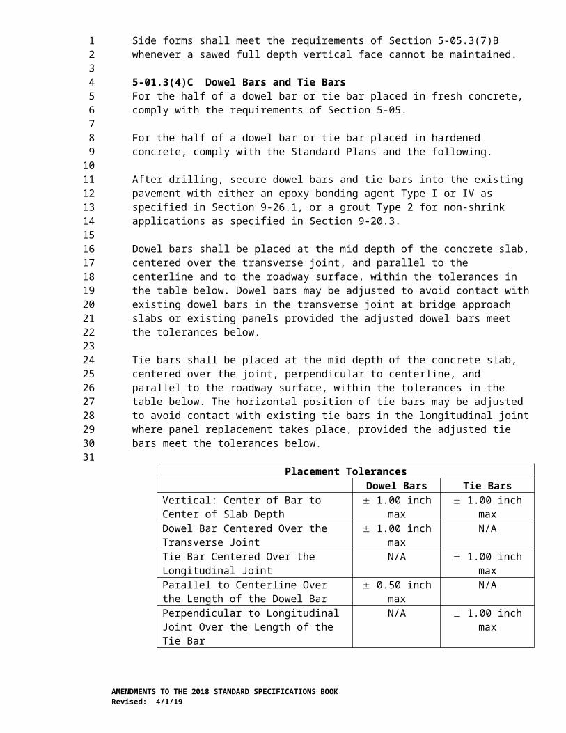
Dowel bars shall be placed at the mid depth of the concrete slab, centered over the transverse joint, and parallel to the centerline and to the roadway surface, within the tolerances in the table below. Dowel bars may be adjusted to avoid contact with existing dowel bars in the transverse joint at bridge approach slabs or existing panels provided the adjusted dowel bars meet the tolerances below.
Tie bars shall be placed at the mid depth of the concrete slab, centered over the joint, perpendicular to centerline, and parallel to the roadway surface, within the tolerances in the table below. The horizontal position of tie bars may be adjusted to avoid contact with existing tie bars in the longitudinal joint where panel replacement takes place, provided the adjusted tie bars meet the tolerances below.
Placement TolerancesDowel Bars Tie Bars
Vertical: Center of Bar to Center of Slab Depth 1.00 inch max 1.00 inch maxDowel Bar Centered Over the Transverse Joint 1.00 inch max N/ATie Bar Centered Over the Longitudinal Joint N/A 1.00 inch maxParallel to Centerline Over the Length of the Dowel Bar
0.50 inch max N/A
Perpendicular to Longitudinal Joint Over the Length of the Tie Bar
N/A 1.00 inch max
Parallel to Roadway Surface Over the Length of the Bar
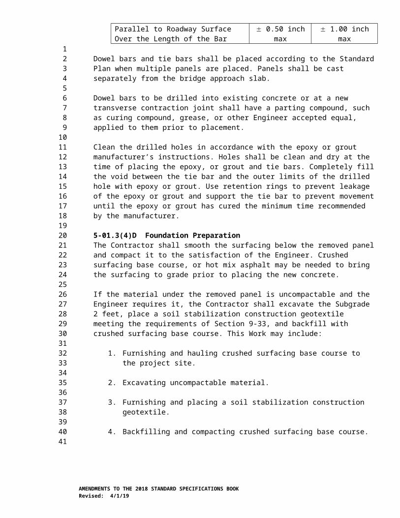
0.50 inch max 1.00 inch max
Dowel bars and tie bars shall be placed according to the Standard Plan when multiple panels are placed. Panels shall be cast separately from the bridge approach slab.
Dowel bars to be drilled into existing concrete or at a new transverse contraction joint shall have a parting compound, such as curing compound, grease, or other Engineer accepted equal, applied to them prior to placement.
Clean the drilled holes in accordance with the epoxy or grout manufacturer’s instructions. Holes shall be clean and dry at the time of placing the epoxy, or grout and tie bars. Completely fill the void between the tie bar and the outer limits of the drilled hole with epoxy or grout. Use retention rings to prevent leakage of the epoxy or grout and support the tie bar to prevent movement until the epoxy or grout has cured the minimum time recommended by the manufacturer.
5-01.3(4)D Foundation PreparationThe Contractor shall smooth the surfacing below the removed panel and compact it to the satisfaction of the Engineer. Crushed surfacing base course, or hot mix asphalt may be needed to bring the surfacing to grade prior to placing the new concrete.
If the material under the removed panel is uncompactable and the Engineer requires it, the Contractor shall excavate the Subgrade 2 feet, place a soil stabilization construction geotextile meeting the requirements of Section 9-33, and backfill with crushed surfacing base course. This Work may include:
1. Furnishing and hauling crushed surfacing base course to the project site.
2. Excavating uncompactable material.
3. Furnishing and placing a soil stabilization construction geotextile.
AMENDMENTS TO THE 2018 STANDARD SPECIFICATIONS BOOKRevised: 4/1/19
123456789
101112
131415161718192021222324252627282930313233343536373839404142
4. Backfilling and compacting crushed surfacing base course.
5. Removing, hauling and restocking any unused crushed surfacing base course.
5-01.3(4)E Concrete FinishingGrade control shall be the responsibility of the Contractor.
All panels shall be struck off level with the adjacent panels and floated to a smooth surface.
Final finish texturing shall meet the requirements of Section 5-05.3(11).
In areas where the Plans do not require grinding, the surface smoothness will be measured with a 10-foot straightedge by the Engineer in accordance with Section 5-05.3(12). If the replacement panel is located in an area that will be ground as part of concrete pavement grinding in accordance with Section 5-01.3(9), the surface smoothness shall be measured, by the Contractor, in conjunction with the smoothness measurement done in accordance with Section 5-01.3(10).
5-01.3(4)F JointsAll transverse and longitudinal joints shall be sawed and sealed in accordance with Section 5-05.3(8). The Contractor may use a hand pushed single blade saw for sawing joints.
5-01.3(4)G Cracked PanelsReplacement panels that crack shall be repaired as specified in Section 5-05.3(22) at no cost to the Contracting Agency. When repairing replacement panels that have cracked, epoxy-coated dowel bars meeting the requirements of Section 9-07.5(1) may be substituted for the corrosion resistant dowel bars specified.
5-01.3(4)H Opening to TrafficOpening to traffic shall meet the requirements of Section 5-05.3(17).
5-01.3(5) Partial Depth Spall RepairThe second sentence of the third paragraph is revised to read:
All sandblasting residue shall be removed.
5-01.3(7) Sealing Existing Concrete Random CracksThe second sentence of the second paragraph is revised to read:
Immediately prior to sealing, the cracks shall be clean.
5-01.3(8) Sealing Existing Longitudinal and Transverse JointThe first sentence of the fifth paragraph is revised to read:
Immediately prior to sealing, the cracks shall be clean.
5-01.3(10) Pavement SmoothnessThis section is revised to read:
AMENDMENTS TO THE 2018 STANDARD SPECIFICATIONS BOOKRevised: 4/1/19
123456789
10111213141516171819202122232425262728293031323334353637383940414243444546474849505152
Pavement surface smoothness for cement concrete pavement grinding on this project will include International Roughness Index (IRI) testing. Ride quality will be evaluated using the Mean Roughness Index (MRI) calculated by averaging the IRI data for the left and right wheel path within the section.
Smoothness Testing Equipment and Operator CertificationUse an inertial profiler and operator that meet the requirements of Section 5-05.3(3)E.
Surface SmoothnessOperate the inertial profiler in accordance with AASHTO R 57. Collect two longitudinal traces, one in each wheel path. Collect the control profile at locations designated in Table 2 prior to any pavement rehabilitation Work on the areas to be tested. Collect an acceptance profile at locations designated in Table 2 after completion of all cement concrete pavement grinding on the project. Profiles shall be collected in a continuous pass including areas excluded from pay adjustments. Provide notice to the Engineer a minimum of seven calendar days prior to testing.
Table 2Locations Requiring MRI Testing
Travel lanes where cement concrete grinding is shown in the plans
Control profile
Additional locations designated by the Engineer Control profile
Travel lanes with completed cement concrete pavement grinding Acceptance profile
Bridges, approach panels and 0.02 miles before and after bridges and approach panels and other excluded areas within lanes requiring testing
Control and acceptance profile
Ramps, Shoulders and Tapers Do not test
Within 30 calendar days after the Contractor’s testing, the Engineer may perform verification testing. If the verification testing shows a difference in MRI greater than the 10 percent, the following resolution process will be followed:
1. The profiles, equipment and procedures will be evaluated to determine the cause of the difference.
2. If the cause of the discrepancy cannot be resolved the pavement shall be retested with both profilers at a mutually agreed time. The two profilers will test the section within 30 minutes of each other. If the retest shows a difference in MRI equal or greater than the percentages shown in Table 2 of AASHTO R 54 the Engineer’s test results will be used for pavement smoothness acceptance.
The Contractor shall evaluate profiles for acceptance or corrective action using the current version of ProVAL and provide the results including the profile data in unfiltered electronic Engineering Research Division (ERD) file format to the Engineer within 3 calendar days of completing each days profile testing. If the profile data files are created using an export option in the manufacturer’s software where filter settings can be specified, use the filter settings that were used to create data files for certification.
AMENDMENTS TO THE 2018 STANDARD SPECIFICATIONS BOOKRevised: 4/1/19
123456789
1011121314151617
181920212223242526272829303132333435363738
Analyze the entire profile. Exclude areas listed in Table 3.
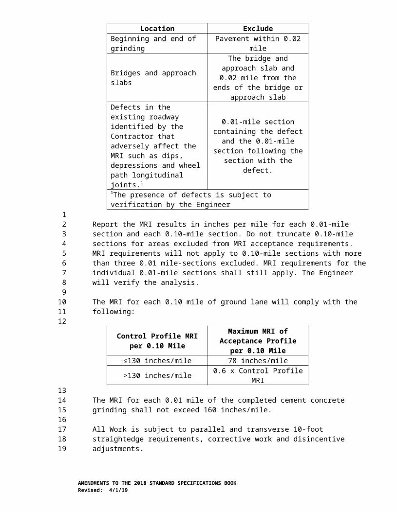
Table 3Areas Excluded from MRI Acceptance Requirements
Location ExcludeBeginning and end of grinding Pavement within 0.02 mile
Bridges and approach slabsThe bridge and approach slab and
0.02 mile from the ends of the bridge or approach slab
Defects in the existing roadway identified by the Contractor that adversely affect the MRI such as dips, depressions and wheel path longitudinal joints.1
0.01-mile section containing the defect and the 0.01-mile section
following the section with the defect.
1The presence of defects is subject to verification by the Engineer
Report the MRI results in inches per mile for each 0.01-mile section and each 0.10-mile section. Do not truncate 0.10-mile sections for areas excluded from MRI acceptance requirements. MRI requirements will not apply to 0.10-mile sections with more than three 0.01 mile-sections excluded. MRI requirements for the individual 0.01-mile sections shall still apply. The Engineer will verify the analysis.
The MRI for each 0.10 mile of ground lane will comply with the following:
Control Profile MRI per 0.10 Mile Maximum MRI of Acceptance Profile per 0.10 Mile
≤130 inches/mile 78 inches/mile>130 inches/mile 0.6 x Control Profile MRI
The MRI for each 0.01 mile of the completed cement concrete grinding shall not exceed 160 inches/mile.
All Work is subject to parallel and transverse 10-foot straightedge requirements, corrective work and disincentive adjustments.
Surface smoothness of travel lanes including areas subject to MRI testing shall not vary more than ⅛ inch from the lower edge of a 10-foot straightedge placed on the surface parallel to the centerline.
The smoothness perpendicular to the centerline will be measured with a 10-foot straightedge within the lanes. There shall be not vertical elevation difference of more than a ¼ inch between lanes.
Pavement that does not meet these requirements will be subject to corrective Work. All corrective Work shall be completed at no additional expense, including traffic control, to the Contracting Agency. Pavement shall be repaired by one or more of the following methods:
1. Diamond grinding.
2. By other method accepted by the Engineer.
AMENDMENTS TO THE 2018 STANDARD SPECIFICATIONS BOOKRevised: 4/1/19
123
456789
101112
131415161718192021222324252627282930313233343536
Repair areas shall be re-profiled to ensure they no longer require corrective Work. With concurrence of the Engineer, a 10-foot straight edge may be used in place of the inertial profiler.
If correction of the roadway as listed above either will not or does not produce satisfactory results as to smoothness or serviceability the Engineer may accept the completed pavement and a credit will be calculated in accordance with Section 5-01.5. Under these circumstances, the decision whether to accept the completed pavement or to require corrective work as described above shall be vested entirely in the Engineer.
5-01.5 PaymentThis section is supplemented with the following:
“Grinding Smoothness Compliance Adjustment”, by calculation.Grinding Smoothness Compliance Adjustments will be based on the requirements in Section 5-01.3(10) and the following calculations:
A smoothness compliance adjustment will be calculated in the sum of minus $100 for each and every section of single traffic lane 0.01 mile in length and $1,000 for each and every section of single traffic lane 0.10 mile in length that does not meet the requirements in Section 5-01.3(10) after corrective Work.
5-02.AP5Section 5-02, Bituminous Surface TreatmentApril 1, 2019
5-02.3(5) Application of AggregatesThe first sentence of the eleventh paragraph is revised to read:
The Contractor shall use a pickup broom in all curbed areas, on all bridges, within city limits, within sensitive areas, and where shown in the Plans both before the application of emulsified asphalt and during the final brooming operation.
5-04.AP5Section 5-04, Hot Mix AsphaltApril 1, 2019
5-04.1 DescriptionThe last sentence of the first paragraph is revised to read:
The manufacture of HMA may include additives or processes that reduce the optimum mixing temperature (Warm Mix Asphalt) or serve as a compaction aid in accordance with these Specifications.
5-04.2 MaterialsThe reference to “Warm Mix Asphalt Additive” is revised to read “HMA Additive”.
5-04.2(1) How to Get an HMA Mix Design on the QPLThe last bullet in the first paragraph is revised to read:
AMENDMENTS TO THE 2018 STANDARD SPECIFICATIONS BOOKRevised: 4/1/19
123456789
10111213141516171819202122232425
26272829303132333435
36373839404142434445464748
• Do not include HMA additives that reduce the optimum mixing temperature or serve as a compaction aid when developing a mix design or submitting a mix design for QPL evaluation. The use of HMA additives is not part of the process for obtaining approval for listing a mix design on the QPL. Refer to Section 5-04.2(2)B.
In the table, “WSDOT Standard Practice QC-8” is revised to read “WSDOT Standard Practice QC-8 located in the WSDOT Materials Manual M 46-01”.
5-04.2(1)C Mix Design Resubmittal for QPL ApprovalItem number 3 of the first paragraph is revised to read:
3. Changes in modifiers used in the asphalt binder.
5-04.2(2)B Using Warm Mix Asphalt ProcessesThis section, including title, is revised to read:
5-04.2(2)B Using HMA AdditivesThe Contractor may, at the Contractor’s discretion, elect to use additives that reduce the optimum mixing temperature or serve as a compaction aid for producing HMA. Additives include organic additives, chemical additives and foaming processes. The use of Additives is subject to the following:
• Do not use additives that reduce the mixing temperature in accordance with Section 5-04.3(6) in the production of High RAP/Any RAS mixtures.
• Before using additives, obtain the Engineer’s approval using WSDOT Form 350-076 to describe the proposed additive and process.
5-04.3(3)A Mixing PlantItem number 5 of the first paragraph is revised to read:
5. Provide HMA sampling equipment that complies with FOP for AASHTO T 168:
• Use a mechanical sampling device accepted by the Engineer, or
• Platforms or devices to enable sampling from the truck transport without entering the truck transport for sampling HMA.
5-04.3(4) Preparation of Existing Paved SurfacesThe first sentence of the fourth paragraph is revised to read:
Unless otherwise allowed by the Engineer, use cationic emulsified asphalt CSS-1, CSS-1h, or Performance Graded (PG) asphalt for tack coat.
5-04.3(6) MixingThe first paragraph is revised to read:
The asphalt supplier shall introduce recycling agent and anti-stripping additive, in the amount designated on the QPL for the mix design, into the asphalt binder prior to shipment to the asphalt mixing plant.
The seventh paragraph is revised to read:
AMENDMENTS TO THE 2018 STANDARD SPECIFICATIONS BOOKRevised: 4/1/19
123456789
10111213141516171819202122232425262728293031323334353637383940414243444546474849505152
Upon discharge from the mixer, ensure that the temperature of the HMA does not exceed the optimum mixing temperature shown on the accepted Mix Design Report by more than 25°F, or as allowed by the Engineer. When an additive is included in the manufacture of HMA, do not heat the additive (at any stage of production including in binder storage tanks) to a temperature higher than the maximum recommended by the manufacturer of the additive.
5-04.3(7) Spreading and FinishingThe last row of the table is revised to read:
3∕8 inch 0.25 feet 0.30 feet
5-04.3(8) Aggregate Acceptance Prior to Incorporation in HMAThe following new paragraph is inserted after the first paragraph:
The Contracting Agency’s combined aggregate bulk specific gravity (Gsb) blend as shown on the HMA Mix Design will be used for VMA calculations until the Contractor submits a written request for a Gsb test. The new Gsb will be used in the VMA calculations for HMA from the date the Engineer receives the written request for a Gsb retest. The Contractor may request aggregate specific gravity (Gsb) testing be performed by the Contracting Agency twice per project. The Gsb blend of the combined stockpiles will be used to calculate voids in mineral aggregate (VMA) of any HMA produced after the new Gsb is determined.
5-04.3(9)A1 Test Section – When Required, When to StopThe following new row is inserted after the second row in Table 9:
VMA Minimum PFi of 0.95 based on the criteria in Section 5-04.3(9)B42
None4
5-04.3(9)A2 Test Section – Evaluating the HMA Mixture in a Test SectionIn Table 9a, the test property “Gradation, Asphalt Binder, and Va” is revised to read “Gradation, Asphalt Binder, VMA, and Va”
In Table 9a, the first column of the third row is revised to read:
Aggregates:Sand Equivalent
Uncompacted Void ContentFracture
5-04.3(9)B3 Mixture Statistical Evaluation – Acceptance TestingIn Table 11, “Va” is revised to read “VMA and Va”
5-04.3(9)B5 Mixture Statistical Evaluation – Composite Pay Factors (CPF)The following new row is inserted above the last row in Table 12:
Voids in Mineral Aggregate (VMA)
2
AMENDMENTS TO THE 2018 STANDARD SPECIFICATIONS BOOKRevised: 4/1/19
123456789
1011
12131415161718192021222324252627
28293031323334
35363738394041
42
5-04.3(9)B7 Mixture Statistical Evaluation – RetestsThe second to last sentence is revised to read:
The sample will be tested for a complete gradation analysis, asphalt binder content, VMA and Va, and the results of the retest will be used for the acceptance of the HMA mixture in place of the original mixture sublot sample test results.
5-04.3(10)A HMA Compaction – General Compaction RequirementsThe last paragraph is revised to read:
On bridge decks and on roadway approaches within five feet of a bridge/back of pavement seat, rollers shall not be operated in a vibratory mode, defined as a mode in which the drum vibrates vertically. However, unless otherwise noted on the plans, rollers may be operated in an oscillatory mode, defined as a mode in which the drum vibrates in the horizontal direction only.
5-04.3(10)C1 HMA Compaction Statistical Evaluation – Lots and SublotsThe bulleted item in the fourth paragraph is revised to read:
• For a compaction lot in progress with a compaction CPF less than 0.75 using an LSL = 91.5, a new compaction lot will begin at the Contractor’s request after the Engineer is satisfied that material conforming to the Specifications can be produced. See also Section 5-04.3(11)F.
5-04.3(10)C2 HMA Compaction Statistical Evaluation – Acceptance TestingIn the table, “WSDOT FOP for AASHTO T 355” is revised to read “FOP for AASHTO T 355”.
5-04.3(10)C3 HMA Statistical Compaction – Price AdjustmentsIn the first paragraph, “WSDOT FOP for AASHTO T 355” is revised to read “FOP for AASHTO T 355”.
The first sentence in the second paragraph is revised to read:
For each HMA compaction lot (that is accepted by Statistical Evaluation) which does not meet the criteria in the preceding paragraph, the compaction lot shall be evaluated in accordance with Section 1-06.2(2)D5 to determine the appropriate Composite Pay Factor (CPF).
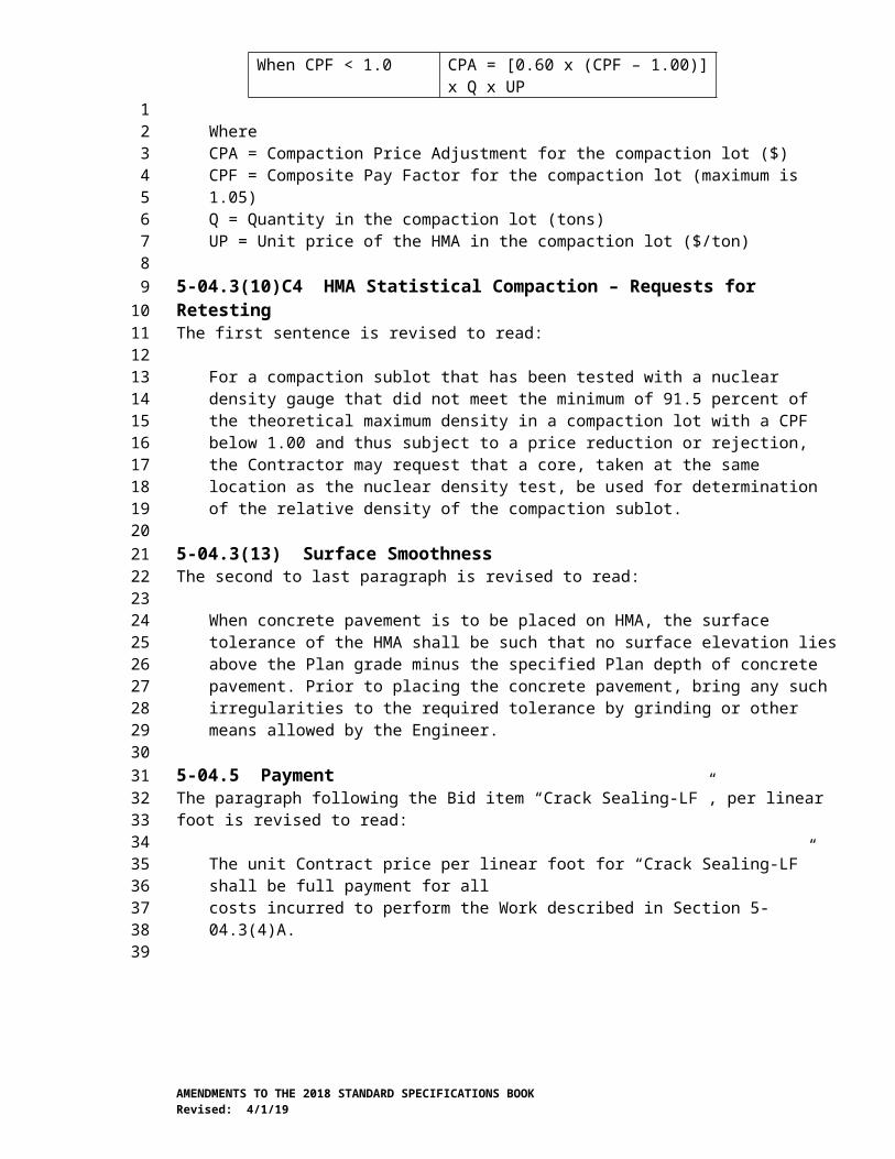
The last two paragraphs are revised to read:
Determine the Compaction Price Adjustment (CPA) from the table below, selecting the equation for CPA that corresponds to the value of CPF determined above.
Calculating HMA Compaction Price Adjustment (CPA)Value of CPF Equation for Calculating CPA
When CPF > 1.00 CPA = [1.00 x (CPF – 1.00)] x Q x UP
When CPF = 1.00 CPA = $0When CPF < 1.0 CPA = [0.60 x (CPF – 1.00)] x Q x
UP
AMENDMENTS TO THE 2018 STANDARD SPECIFICATIONS BOOKRevised: 4/1/19
123456789
10111213141516171819202122232425262728293031323334353637383940414243
44

WhereCPA = Compaction Price Adjustment for the compaction lot ($)CPF = Composite Pay Factor for the compaction lot (maximum is 1.05)Q = Quantity in the compaction lot (tons)UP = Unit price of the HMA in the compaction lot ($/ton)
5-04.3(10)C4 HMA Statistical Compaction – Requests for RetestingThe first sentence is revised to read:
For a compaction sublot that has been tested with a nuclear density gauge that did not meet the minimum of 91.5 percent of the theoretical maximum density in a compaction lot with a CPF below 1.00 and thus subject to a price reduction or rejection, the Contractor may request that a core, taken at the same location as the nuclear density test, be used for determination of the relative density of the compaction sublot.
5-04.3(13) Surface SmoothnessThe second to last paragraph is revised to read:
When concrete pavement is to be placed on HMA, the surface tolerance of the HMA shall be such that no surface elevation lies above the Plan grade minus the specified Plan depth of concrete pavement. Prior to placing the concrete pavement, bring any such irregularities to the required tolerance by grinding or other means allowed by the Engineer.
5-04.5 PaymentThe paragraph following the Bid item “Crack Sealing-LF”, per linear foot is revised to read:
The unit Contract price per linear foot for “Crack Sealing-LF” shall be full payment for allcosts incurred to perform the Work described in Section 5-04.3(4)A.
5-05.AP5Section 5-05, Cement Concrete PavementApril 1, 2019
5-05.1 DescriptionIn the first paragraph, “portland cement concrete” is revised to read “cement concrete”.
5-05.2 MaterialsIn the first paragraph, the reference to “Portland Cement” is revised to read:
Cement 9-01
In the first paragraph, the section reference for Concrete Patching Material is revised to read “9-20.1”.
The second paragraph is revised to read:
Cementitious materials are considered to be the following: portland cement, blended hydraulic cement, fly ash, ground granulated blast furnace slag and microsilica fume.
AMENDMENTS TO THE 2018 STANDARD SPECIFICATIONS BOOKRevised: 4/1/19
123456789
101112131415161718192021222324252627282930313233
34353637383940414243444546474849

5-05.3(1) Concrete Mix Design for PavingThe table title in item number 4 is revised to read Concrete Batch Weights.
In item 4a, “Portland Cement” is revised to read “Cement”.
5-05.3(3)E Smoothness Testing EquipmentThis section is revised to read:
Inertial profilers shall meet all requirements of AASHTO M 328 and be certified in accordance with AASHTO R 56 within the preceding 12 months.
The inertial profiler operator shall be certified as required by AASHTO R 56 within three years preceding profile measurement.
Equipment or operator certification by other states or a profiler certification facility will be accepted provided the certification meets the requirements of AASHTO R 56. Documentation verifying certification by another state shall be submitted to the Engineer a minimum of 14 calendar days prior to profile measurement. Equipment certification documentation shall include the information required by part 8.5 and 8.6 of AASHTO R 56. Operator documentation shall include a statement from the certifying state that indicates the operator is certified to operate the inertial profiler to be used on the project. The decision whether another state’s certification meets the requirements of AASHTO R 56 shall be vested entirely in the Engineer.
5-05.3(4) Measuring and Batching MaterialsItem number 2 is revised to read:
2. Batching Materials – On all projects requiring more than 2,500 cubic yards of concrete for paving, the batching plant shall be equipped to proportion aggregates and cement by weight by means of automatic and interlocked proportioning devices of accepted type.
5-05.3(4)A Acceptance of Portland Cement Concrete PavementThis section’s title is revised to read:
Acceptance of Portland Cement or Blended Hydraulic Cement Concrete Pavement
The first sentence is revised to read:
Acceptance of portland cement or blended hydraulic cement concrete pavement shall be as provided under statistical or nonstatistical acceptance.
5-05.3(7) Placing, Spreading, and Compacting ConcreteThis section’s content is deleted.
5-05.3(10) Tie Bars and Corrosion Resistant Dowel BarsThe first sentence of the last paragraph is revised to read:
The tie bar holes shall be clean before grouting.
5-05.3(12) Surface SmoothnessThis section is revised to read:
AMENDMENTS TO THE 2018 STANDARD SPECIFICATIONS BOOKRevised: 4/1/19
123456789
10111213141516171819202122232425262728293031323334353637383940414243444546474849505152
Pavement surface smoothness for this project will include International Roughness Index (IRI) testing. The Contractor shall perform IRI testing on each through lane, climbing lane, and passing lane, greater than 0.25 mile in length and these lanes will be subject to incentive/disincentive adjustments. Ride quality will be evaluated using the Mean Roughness Index (MRI) calculated by averaging the IRI data for the left and right wheel path within the section.
Ramps, shoulders and tapers will not be included in MRI testing for pavement smoothness and will not be subject to incentive adjustments. All Work is subject to parallel and transverse 10-foot straightedge requirements, corrective work and disincentive adjustments.
Operate the inertial profiler in accordance with AASHTO R 57. Collect two longitudinal traces, one in each wheel path. Collect profile data after completion of all concrete paving on the project in a continuous pass including areas excluded from pay adjustments. Provide notice to the Engineer a minimum of seven calendar days prior to testing.
Within 30 calendar days after the Contractor’s testing, the Engineer may perform verification testing. If the verification testing shows a difference in MRI greater than the percentages shown in Table 2 of AASHTO R 54 the following resolution process will be followed:
1. The profiles, equipment and procedures will be evaluated to determine the cause of the difference.
2. If the cause of the discrepancy cannot be resolved the pavement shall be retested with both profilers at a mutually agreed time. The two profilers will test the section within 30 minutes of each other. If the retest shows a difference in MRI equal or greater than the percentages shown in Table 2 of AASHTO R 54 the Engineer’s test results will be used to establish pay adjustments.
Surface smoothness of travel lanes not subject to MRI testing will be measured with a 10-foot straightedge no later than 5:00 p.m. of the day following the placing of the concrete. The completed surface of the wearing course shall not vary more than ⅛ inch from the lower edge of a 10-foot straightedge placed on the surface parallel to the centerline.
Smoothness perpendicular to the centerline will be measured with a 10-foot straightedge across all lanes with the same cross slope, including shoulders when composed of cement concrete pavement. The overlapping 10-foot straightedge measurement shall be discontinued at a point 6 inches from the most extreme outside edge of the finished cement concrete pavement. The completed surface of the wearing course shall not vary more than ¼ inch from the lower edge of a 10-foot straightedge placed on the surface perpendicular to the centerline. Any deviations in excess of the above tolerances shall be corrected.
The Contractor shall evaluate profiles for acceptance, incentive payments, disincentive payments, or corrective action using the current version of ProVAL and provide the results including the profile data in unfiltered electronic Engineering Research Division
AMENDMENTS TO THE 2018 STANDARD SPECIFICATIONS BOOKRevised: 4/1/19
123456789
10111213141516171819202122232425262728293031323334353637383940414243444546474849505152

(ERD) file format to the Engineer within 2 calendar days of completing testing each section of pavement. If the profile data files are created using an export option in the manufacturer’s software where filter settings can be specified, use the filter settings that were used to create data files for certification. Analyze the entire profile. Exclude any areas specifically identified in the Contract. Exclude from the analysis the first 100 feet after the start of the paving operations and last 100 feet prior to the end of the paving operation, the first 100 feet on either side of bridge Structures and bridge approach slab. Report the MRI results in inches per mile for each 52.8 foot section and horizontal distance measurements in project stationing to the nearest foot. Include pay adjustments in the results. The Engineer will verify the analysis.
Corrective work for pavement smoothness may be taken by the Contractor prior to MRI testing. After completion of the MRI testing the Contractor shall measure the smoothness of each 52.8-foot section with an MRI greater than 125 inches per mile with a 10-foot straightedge within 14 calendar days or as allowed by the Engineer. The Contractor shall identify all locations that require corrective work and provide the straight edge measurements at each location that exceeds the allowable limit to the Engineer. If all measurements in a 52.8-foot section comply with smoothness requirements, the Contractor shall provide the maximum measurement to the Engineer and a statement that corrective work is not required. Unless allowed by the Engineer, corrective work shall be taken by the Contractor for pavement identified by the Contractor or Engineer that does not meet the following requirements:
1. The completed surface shall be of uniform texture, smooth, uniform as to crown and grade, and free from defects of all kinds.
2. The completed surface shall not vary more than ⅛ inch from the lower edge of a 10-foot straightedge placed on the surface parallel to the centerline.
3. The completed surface shall vary not more than ¼ inch in 10 feet from the rate of transverse slope shown in the Plans.
All corrective work shall be completed at no additional expense, including traffic control, to the Contracting Agency. Corrective work shall not begin until the concrete has reached its design strength unless allowed by the Engineer. Pavement shall be repaired by one or more of the following methods:
1. Diamond grinding; repairs shall not reduce pavement thickness by more than ¼ inch less than the thickness shown in the Plans. When required by the Engineer, the Contractor shall verify the thickness of the concrete pavement by coring. Thickness reduction due to corrective work will not be included in thickness measurements for calculating the Thickness Deficiency in Section 5-05.5(1)A.
2. Removal and replacement of the cement concrete pavement.
3. By other method allowed by the Engineer.
For repairs following MRI testing the repaired area shall be checked by the Contractor with a 10-foot straightedge to ensure it no longer requires corrective work. With concurrence of the Engineer an inertial profiler may be used in place of the 10-foot straight edge.
AMENDMENTS TO THE 2018 STANDARD SPECIFICATIONS BOOKRevised: 4/1/19
123456789
10111213141516171819202122232425262728293031323334353637383940414243444546474849505152

If correction of the roadway as listed above either will not or does not produce satisfactory results as to smoothness or serviceability the Engineer may accept the completed pavement and a credit will be calculated in accordance with Section 5-05.5. The credit will be in addition to the price adjustment for MRI. Under these circumstances, the decision whether to accept the completed pavement or to require corrective work as described above shall be vested entirely in the Engineer.
5-05.3(22) Repair of Defective Pavement SlabsThe last sentence of the fourth paragraph is revised to read:
All sandblasting residue shall be removed.
5-05.4 MeasurementItem number 3 of the second paragraph is revised to read:
3. The depth shall be determined in accordance with Section 5-05.5(1). The depth utilized to calculate the volume shall not exceed the Plan depth plus 0.04 feet.
The third paragraph is revised to read:
The volume of cement concrete pavement in each thickness lot shall equal the measured length × width × thickness measurement.
The last paragraph is revised to read:
The calculation for cement concrete compliance adjustment is the volume of concrete represented by the CPF and the Thickness deficiency adjustment.
5-05.5 PaymentThe paragraph following the Bid item “Cement Conc. Pavement”, per cubic yard is supplemented with the following:
All costs associated with performing the magnetic pulse induction thickness testing shall be included in the unit Contract price per cubic yard for “Cement Conc. Pavement”.
The Bid item “Ride Smoothness Compliance Adjustment”, by calculation, and the paragraph following this bid item are revised to read:
“Ride Smoothness Compliance Adjustment”, by calculation.
Smoothness Compliance Adjustments will be based on the requirements in Section 5-05.3(12) and the following calculations:
1. Final MRI acceptance and incentive/disincentive payments for pavement smoothness will be calculated as the average of the ten 52.8-foot sections in each 528 feet in accordance with the price adjustment schedule.
a. For sections of a lane that are a minimum of 52.8 feet and less than 528 feet, the price adjustment will be calculated using the average of the 52.8 foot MRI values and the price adjustment prorated for the length of the section.
AMENDMENTS TO THE 2018 STANDARD SPECIFICATIONS BOOKRevised: 4/1/19
123456789
10111213141516171819202122232425262728293031323334353637383940414243444546474849505152
b. MRI values per 52.8-feet that were measured prior to corrective work will be included in the 528 foot price adjustment for sections with corrective work.
2. In addition to the price adjustment for MRI a smoothness compliance adjustment will be calculated in the sum of minus $1000.00 for each and every section of single traffic lane 52.8 feet in length in that does not meet the 10-foot straight edge requirements in Section 5-05.3(12) after corrective Work.
Price Adjustment ScheduleMRI for each 528 ft.
sectionPay Adjustment
Schedulein. / mi. $ / 0.10 mi.
< 30 240030 240031 232032 224033 216034 208035 200036 192037 184038 176039 168040 160041 152042 144043 136044 128045 120046 112047 104048 96049 88050 80051 72052 64053 56054 48055 40056 32057 24058 16059 8060 061 062 063 064 065 066 067 0
AMENDMENTS TO THE 2018 STANDARD SPECIFICATIONS BOOKRevised: 4/1/19
123456789
10

68 069 070 071 072 073 074 075 076 -8077 -16078 -24079 -32080 -40081 -48082 -56083 -64084 -72085 -80086 -88087 -96088 -104089 -112090 -120091 -128092 -136093 -144094 -152095 -160096 -168097 -176098 -184099 -1920100 -2000101 -2080102 -2160103 -2240104 -2320105 -2400106 -2480107 -2560108 -2640109 -2720110 -2800111 -2880112 -2960113 -3040114 -3120115 -3200116 -3280117 -3360118 -3440119 -3520120 -3600121 -3680
AMENDMENTS TO THE 2018 STANDARD SPECIFICATIONS BOOKRevised: 4/1/19

122 -3760123 -3840124 -3920
≥125 -4000
The bid item “Portland Cement Concrete Compliance Adjustment”, by calculation, and the paragraph following this bid item are revised to read:
“Cement Concrete Compliance Adjustment”, by calculation.
Payment for “Cement Concrete Compliance Adjustment” will be calculated by multiplying the unit Contract price for the cement concrete pavement, times the volume for adjustment, times the percent of adjustment determined from the calculated CPF and the Deficiency Adjustment listed in Section 5-05.5(1)A.
5-05.5(1) Pavement ThicknessThis section is revised to read:
Cement concrete pavement shall be constructed in accordance with the thickness requirements in the Plans and Specifications. Tolerances allowed for Subgrade construction and other provisions, which may affect thickness, shall not be construed to modify such thickness requirements.
Thickness measurements in each lane paved shall comply with the following:
Thickness Testing of Cement Concrete PavementThickness Lot Size 15 panels maximum
Thickness test location determined by Engineer will select testing locations in accordance with WSDOT TM 716 method B.
Sample method AASHTO T 359
Sample preparation performed by Contractor provides, places, and secures disks in the presence of the Engineer1
Measurement method AASHTO T 359Thickness measurement performed by Contractor, in the presence of the Engineer2
1Reflectors shall be located at within 0.5 feet of the center of the panel. The Contractor shall supply a sufficient number of 300 mm-diameter round reflectors meeting the requirements of AASHTO T 359 to accomplish the required testing.2The Contractor shall provide all equipment and materials needed to perform the testing.
Thickness measurements shall be rounded to the nearest 0.01 foot.
Each thickness test location where the pavement thickness is deficient by more than 0.04 foot, shall be subject to price reduction or corrective action as shown in Table 2.
Table 2Thickness Deficiency
0.04’ < Thickness Deficiency ≤ 0.06’ 100.06’ < Thickness deficiency ≤ 0.08’ 25
Thickness deficiency > 0.08’Remove and replace the panels or the panels may be accepted with no payment at the discretion of the Engineer.
AMENDMENTS TO THE 2018 STANDARD SPECIFICATIONS BOOKRevised: 4/1/19
123456789
101112131415161718192021
222324252627
28

The price reduction shall be computed by multiplying the percent price reduction in Table 2 by the unit Contract price by the volume of pavement represented by the thickness test lot.
Additional cores may be taken by the Contractor to determine the limits of an area that has a thickness deficiency greater than 0.04 feet. Cores shall be taken at the approximate center of the panel. Only the panels within the limits of the deficiency area as determined by the cores will be subject to a price reduction or corrective action. The cores shall be taken in the presence of the Engineer and delivered to the Engineer for measurement. All costs for the additional cores including filling the core holes with patching material meeting the requirements of Section 9-20 will be the responsibility of the Contractor.
5-05.5(1)A Thickness Deficiency of 0.05 Foot or LessThis section, including title, is revised to read:
5-05.5(1)A Vacant
5-05.5(1)B Thickness Deficiency of More Than 0.05 FootThis section, including title, is revised to read:
5-05.5(1)B Vacant
6-01.AP6Section 6-01, General Requirements for StructuresJanuary 7, 2019
This section is supplemented with the following new subsections:
6-01.16 Repair of Defective Work6-01.16(1) GeneralWhen using repair procedures that are described elsewhere in the Contract Documents, the Working Drawing submittal requirements of this Section shall not apply to those repairs unless noted otherwise.
Repair procedures for defective Work shall be submitted as Type 2 Working Drawings. Type 2E Working Drawings shall be submitted when required by the Engineer. As an alternative to submitting Type 2 or 2E Working Drawings, defective Work within the limits of applicability of a pre-approved repair procedure may be repaired using that procedure. Repairs using a pre-approved repair procedure shall be submitted as a Type 1 Working Drawing.
Pre-approved repair procedures shall consist of the following:
• The procedures listed in Section 6-01.16(2)
• For precast concrete, repair procedures in the annual plant approval process documents that have been approved for use by the Contracting Agency.
All Working Drawings for repair procedures shall include:
AMENDMENTS TO THE 2018 STANDARD SPECIFICATIONS BOOKRevised: 4/1/19
123456789
1011121314151617181920212223242526
27282930313233343536373839404142434445464748495051
• A description of the defective Work including location, extent and pictures
• Materials to be used in the repair. Repairs using manufactured products shall include written manufacturer recommendations for intended uses of the product, surface preparation, mixing, aggregate extension (if applicable), ambient and surface temperature limits, placement methods, finishing and curing.
• Construction procedures
• Plan details of the area to be repaired
• Calculations for Type 2E Working Drawings
Material manufacturer’s instructions and recommendations shall supersede any conflicting requirements in pre-approved repair procedures.
The Engineer shall be notified prior to performing any repair procedure and shall be given an opportunity to inspect the repair work being performed.
6-01.16(2) Pre-Approved Repair Procedures6-01.16(2)A Concrete Spalls and Poor Consolidation (Rock Pockets, Honeycombs, Voids, etc.)This repair shall be limited to the following areas:
• Areas that are not on top Roadway surfaces (with or without an overlay) including but not limited to concrete bridge decks, bridge approach slabs or cement concrete pavement
• Areas that are not underwater
• Areas that are not on precast barrier, except for the bottom 4 inches (but not to exceed 1 inch above blockouts)
• Areas that do not affect structural adequacy as determined by the Engineer.
The repair procedure is as follows:
1. Remove all loose and unsound concrete. Impact breakers shall not exceed 15 pounds in weight when removing concrete adjacent to reinforcement or other embedments and shall not exceed 30 pounds in weight otherwise. Operate impact breakers at angles less than 45 degrees as measured from the surface of the concrete to the tool and moving away from the edge of the defective Work. Concrete shall be completely removed from exposed surfaces of existing steel reinforcing bars. If half or more of the circumference of any steel reinforcing bar is exposed, if the reinforcing bar is loose or if the bond to existing concrete is poor then concrete shall be removed at least ¾ inch behind the reinforcing bar. Do not damage any existing reinforcement. Stop work and allow the Engineer to inspect the repair
AMENDMENTS TO THE 2018 STANDARD SPECIFICATIONS BOOKRevised: 4/1/19
123456789
101112131415161718192021222324252627282930313233343536373839404142434445464748495051

area after removing all loose and unsound concrete. Submit a modified repair procedure when required by the Engineer.
2. Square the edges of the repair area by cutting an edge perpendicular to the concrete surface around the repair area. The geometry of the repair perimeter shall minimize the edge length and shall be rectangular with perpendicular edges, avoiding reentrant corners. The depth of the cut shall be a minimum of ¾ inch, but shall be reduced if necessary to avoid damaging any reinforcement. For repairs on vertical surfaces, the top edge shall slope up toward the front at a 1-vertical-to-3-horizontal slope.
3. Remove concrete within the repair area to a depth at least matching the cut depth at the edges. Large variations in the depth of removal within short distances shall be avoided. Roughen the concrete surface. The concrete surface should be roughened to at least Concrete Surface Profile (CSP) 5 in accordance with ICRI Guideline No. 310.2R, unless a different CSP is recommended by the patching material manufacturer.
4. Inspect the concrete repair surface for delaminations, debonding, microcracking and voids using hammer tapping or a chain drag. Remove any additional loose or unsound concrete in accordance with steps 1 through 3.
5. Select a patching material in accordance with Section 9-20.2 that is appropriate for the repair location and thickness. The concrete patching material shall be pumpable or self-consolidating as required for the type of placement that suits the repair. The patching material shall have a minimum compressive strength at least equal to the specified compressive strength of the concrete.
6. Prepare the concrete surface and reinforcing steel in accordance with the patching material manufacturer’s recommendations. At a minimum, clean the concrete surfaces (including perimeter edges) and reinforcing steel using oil-free abrasive blasting or high-pressure (minimum 5,000 psi) water blasting. All dirt, dust, loose particles, rust, laitance, oil, film, microcracked/bruised concrete or foreign material of any sort shall be removed. Damage to the epoxy coating on steel reinforcing bars shall be repaired in accordance with Section 6-02.3(24)H.
7. Construct forms if necessary, such as for patching vertical or overhead surfaces or where patching extends to the edge or corner of a placement.
8. When recommended by the patching material manufacturer, saturate the concrete in the repair area and remove any free water at the concrete surface to obtain a saturated surface dry (SSD) substrate. When recommended by the patching material manufacturer, apply a primer, scrub coat or bonding agent to the existing surfaces. Epoxy
AMENDMENTS TO THE 2018 STANDARD SPECIFICATIONS BOOKRevised: 4/1/19
123456789
101112131415161718192021222324252627282930313233343536373839404142434445464748495051
bonding agents, if used, shall be Type II or Type V in accordance with Section 9-26.1.
9. Place and consolidate the patching material in accordance with the manufacturer’s recommendations. Work the material firmly into all surfaces of the repair area with sufficient pressure to achieve proper bond to the concrete.
10. The patching material shall be textured, cured and finished in accordance with the patching material manufacturer’s recommendations and/or the requirements for the repaired component. Protect the newly placed patch from vibration in accordance with Section 6-02.3(6)D.
11. When the completed repair does not match the existing concrete color and will be visible to the public, a sand and cement mixture that is color matched to the existing concrete shall be rubbed, brushed, or applied to the surface of the patching material and the concrete.
6-01.10 Utilities Supported by or Attached to BridgesIn the third paragraph, “Federal Standard 595” is revised to read “SAE AMS Standard 595”.
6-01.12 Final CleanupThe second sentence of the first paragraph is revised to read:
Structure decks shall be clean.
The second paragraph is deleted.
6-02.AP6Section 6-02, Concrete StructuresApril 1, 2019
6-02.1 DescriptionThe first sentence is revised to read:
This Work consists of the construction of all Structures (and their parts) made of portland cement or blended hydraulic cement concrete with or without reinforcement, including bridge approach slabs.
6-02.2 MaterialsIn the first paragraph, the references to “Portland Cement” and “Aggregates for Portland Cement Concrete” are revised to read:
Cement 9-01Aggregates for Concrete 9-03.1
The reference to metakaolin is deleted.
6-02.3(2) Proportioning MaterialsThe second paragraph is revised to read:
AMENDMENTS TO THE 2018 STANDARD SPECIFICATIONS BOOKRevised: 4/1/19
123456789
1011121314151617181920212223242526272829303132
33343536373839404142434445464748495051
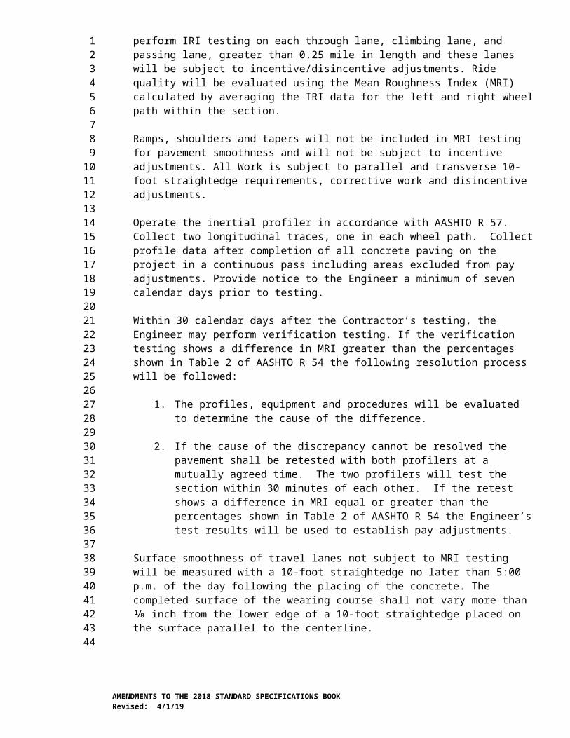
Unless otherwise specified, the Contractor shall use Type I or II portland cement or blended hydraulic cement in all concrete as defined in Section 9-01.2(1).
The last sentence of the fifth paragraph is revised to read:
With the Engineer’s written concurrence, microsilica fume may be used in all classifications of Class 4000, Class 3000, and commercial concrete and is limited to a maximum of 10 percent of the cementitious material.
6-02.3(2)A Contractor Mix DesignThe last sentence of the last paragraph is revised to read:
For all other concrete, air content shall be a minimum of 4.5 percent and a maximum of 7.5 percent for all concrete placed above the finished ground line unless noted otherwise.
6-02.3(2)A1 Contractor Mix Design for Concrete Class 4000DItem number 5 of the first paragraph is deleted.
Item number 6 of the first paragraph (after the preceding Amendment is applied) is renumbered to 5.
6-02.3(2)B Commercial ConcreteThe second paragraph is revised to read:
Where concrete Class 3000 is specified for items such as, culvert headwalls, plugging culverts, concrete pipe collars, pipe anchors, monument cases, Type PPB, PS, I, FB and RM signal standards, pedestals, cabinet bases, guardrail anchors, fence post footings, sidewalks, concrete curbs, curbs and gutters, and gutters, the Contractor may use commercial concrete. If commercial concrete is used for sidewalks, concrete curbs, curbs and gutters, and gutters, it shall have a minimum cementitious material content of 564 pounds per cubic yard of concrete, shall be air entrained, and the tolerances of Section 6-02.3(5)C shall apply.
6-02.3(4) Ready-Mix ConcreteThe first sentence of the first paragraph is revised to read:
All concrete, except lean concrete, shall be batched in a prequalified manual, semi-automatic, or automatic plant as described in Section 6-02.3(4)A.
6-02.3(4)D Temperature and Time For PlacementThe following is inserted after the first sentence of the first paragraph:
The upper temperature limit for placement for Class 4000D concrete may be increased to a maximum of 80°F if allowed by the Engineer.
6-02.3(5)C Conformance to Mix DesignItem number 1 of the second paragraph is revised to read:
1. Cement weight plus 5 percent or minus 1 percent of that specified in the mix design.
AMENDMENTS TO THE 2018 STANDARD SPECIFICATIONS BOOKRevised: 4/1/19
123456789
10111213141516171819202122232425262728293031323334353637383940414243444546474849505152

6-02.3(6)A1 Hot Weather ProtectionThe first paragraph is revised to read:
The Contractor shall provide concrete within the specified temperature limits. Cooling of the coarse aggregate piles by sprinkling with water is permitted provided the moisture content is monitored, the mixing water is adjusted for the free water in the aggregate and the coarse aggregate is removed from at least 1 foot above the bottom of the pile. Sprinkling of fine aggregate piles with water is not allowed. Refrigerating mixing water or replacing all or part of the mixing water with crushed ice is permitted, provided the ice is completely melted by placing time.
The second sentence of the second paragraph is revised to read:
These surfaces include forms, reinforcing steel, steel beam flanges, and any others that touch the concrete.
6-02.3(7) VacantThis section, including title, is revised to read:
6-02.3(7) TolerancesUnless noted otherwise, concrete construction tolerances shall be in accordance with this section. Tolerances in this section do not apply to cement concrete pavement.
Horizontal deviation of roadway crown points, cross-slope break points, and curb, barrier or railing edges from alignment or work line: ±1.0 inch
Deviation from plane: ±0.5 inch in 10 feet
Deviation from plane for roadway surfaces: ±0.25 inch in 10 feet
Deviation from plumb or specified batter: ±0.5 inch in 10 feet, but not to exceed a total of ±1.5 inches
Vertical deviation from profile grade for roadway surfaces: ±1 inch
Vertical deviation of top surfaces (except roadway surfaces): ±0.75 inch
Thickness of bridge decks and other structural slabs not at grade: ±0.25 inch
Length, width and thickness of elements such as columns, beams, crossbeams, diaphragms, corbels, piers, abutments and walls, including dimensions to construction joints in initial placements: +0.5 inch, -0.25 inch
Length, width and thickness of spread footing foundations: +2 inches, -0.5 inch
Horizontal location of the as-placed edge of spread footing foundations: The greater of ±2% of the horizontal dimension of the foundation perpendicular to the edge and ±0.5 inch. However, the tolerance shall not exceed ±2 inches.
Location of opening, insert or embedded item at concrete surface: ±0.5 inch
Cross-sectional dimensions of opening: ±0.5 inch
AMENDMENTS TO THE 2018 STANDARD SPECIFICATIONS BOOKRevised: 4/1/19
123456789
10111213141516171819202122232425262728293031323334353637383940414243444546474849505152

Bridge deck, bridge approach slab, and bridge traffic barrier expansion joint gaps with a specified temperature range, measured at a stable temperature: ±0.25 inch
Horizontal deviation of centerline of bearing pad, oak block or other bearing assembly: ±0.125 inch
Horizontal deviation of centerline of supported element from centerline of bearing pad, oak block or other bearing assembly ±0.25 inch
Vertical deviation of top of bearing pad, oak block or other bearing assembly: ±0.125 inch
6-02.3(10)C Finishing EquipmentThe first paragraph is revised to read:
The finishing machine shall be self-propelled and be capable of forward and reverse movement under positive control. The finishing machine shall be equipped with augers and a rotating cylindrical single or double drum screed. The finishing machine shall have the necessary adjustments to produce the required cross section, line, and grade. The finishing machine shall be capable of raising the screeds, augers, and any other parts of the finishing mechanical operation to clear the screeded surface, and returning to the specified grade under positive control. Unless otherwise allowed by the Engineer, a finishing machine manufacturer technical representative shall be on site to assist the first use of the machine on the Contract.
The first sentence of the second paragraph is revised to read:
For bridge deck widening of 20 feet or less, and for bridge approach slabs, or where jobsite conditions do not allow the use of the conventional configuration finishing machines, or modified conventional machines as described above; the Contractor may submit a Type 2 Working Drawing proposing the use of a hand-operated motorized power screed such as a “Texas” or “Bunyan” screed.
6-02.3(10)D4 Monitoring Bridge Deck Concrete Temperature After PlacementThis section, including title, is revised to read:
6-02.3(10)D4 Vacant
6-02.3(10)D5 Bridge Deck Concrete Finishing and TexturingIn the third subparagraph of the first paragraph, the last sentence is revised to read:
The Contractor shall texture the bridge deck surface to within 3-inches minimum and 24-inches maximum of the edge of concrete at expansion joints, within 1-foot minimum and 2-feet maximum of the curb line, and within 3-inches minimum and 9-inches maximum of the perimeter of bridge drain assemblies.
6-02.3(10)F Bridge Approach Slab Orientation and AnchorsThe second to last paragraph is revised to read:
The compression seal shall be a 2½ inch wide gland and shall conform to Section 9-04.1(4).
AMENDMENTS TO THE 2018 STANDARD SPECIFICATIONS BOOKRevised: 4/1/19
123456789
10111213141516171819202122232425262728293031323334353637383940414243444546474849505152
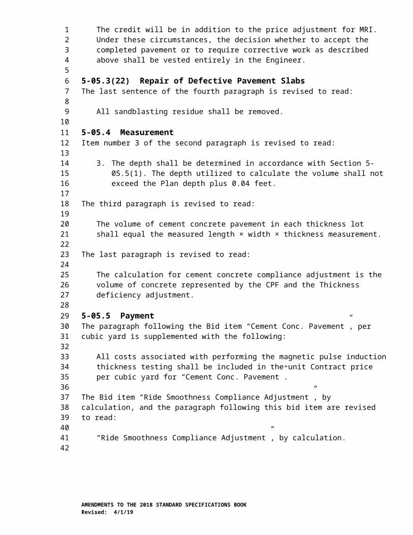
The last paragraph is deleted.
6-02.3(13)A Strip Seal Expansion Joint SystemIn item number 3 of the third paragraph, “Federal Standard 595” is revised to read “SAE AMS Standard 595”.
6-02.3(13)B Compression Seal Expansion Joint SystemThe first paragraph is revised to read:
Compression seal glands shall conform to Section 9-04.1(4) and be sized as shown in the Plans.
6-02.3(14)C Pigmented Sealer for Concrete SurfacesThis section is supplemented with the following new paragraph:
Pigmented Sealer Materials shall be a product listed in the current WSDOT Qualified Products List (QPL). If the pigmented sealer material is not listed in the current WSDOT QPL, a sample shall be submitted to the State Materials Laboratory in Tumwater for evaluation and acceptance in accordance with Section 9-08.3.
6-02.3(20) Grout for Anchor Bolts and Bridge BearingsThe second, third and fourth paragraphs are revised to read:
Grout shall be a workable mix with a viscosity that is suitable for the intended application. Grout shall not be placed outside of the manufacturer recommended range of thickness. The Contractor shall receive concurrence from the Engineer before using the grout.
Field grout cubes and cylinders shall be fabricated and tested in accordance with Section 9-20.3 when requested by the Engineer, but not less than once per bridge pier or once per day.
Before placing grout, the substrate on which it is to be placed shall be prepared as recommended by the manufacturer to ensure proper bonding. The grout shall be cured as recommended by the manufacturer. The grout may be loaded when a minimum of 4,000 psi compressive strength is attained.
The fifth paragraph is deleted.
6-02.3(23) Opening to TrafficThis section is supplemented with the following new paragraph:
After curing bridge approach slabs in accordance with Section 6-02.3(11), thebridge approach slabs may be opened to traffic when a minimum compressive strengthof 2,500 psi is achieved.
6-02.3(24)C Placing and FasteningThis section is revised to read:
The Contractor shall position reinforcing steel as the Plans require and shall ensure that the steel is set within specified tolerances. Adjustments to reinforcing details outside of
AMENDMENTS TO THE 2018 STANDARD SPECIFICATIONS BOOKRevised: 4/1/19
123456789
10111213141516171819202122232425262728293031323334353637383940414243444546474849505152
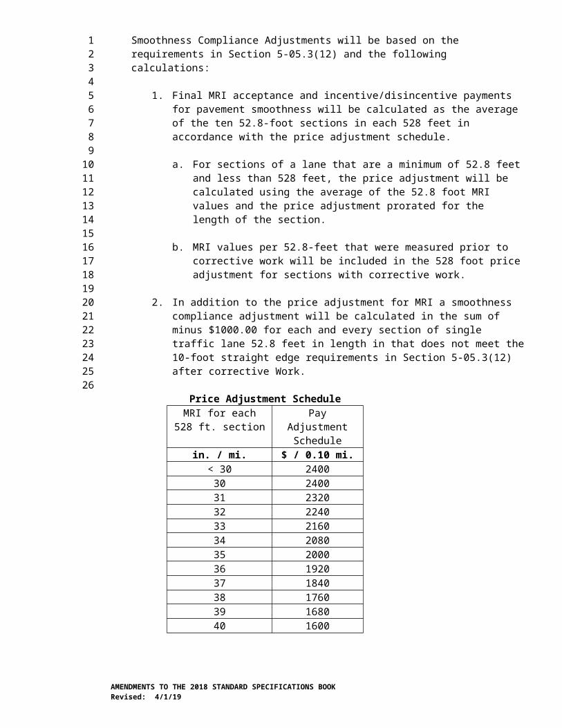
specified tolerances to avoid interferences and for other purposes are acceptable when approved by the Engineer.
When spacing between bars is 1 foot or more, they shall be tied at all intersections. When spacing is less than 1 foot, every other intersection shall be tied. If the Plans require bundled bars, they shall be tied together with wires at least every 6 feet. All epoxy-coated bars in the top mat of the bridge deck shall be tied at all intersections, however they may be tied at alternate intersections when spacing is less than 1 foot in each direction and they are supported by continuous supports meeting all other requirements of supports for epoxy-coated bars. Other epoxy-coated bars shall also be tied at all intersections, but shall be tied at alternate intersections when spacing is less than 1 foot in each direction. Wire used for tying epoxy-coated reinforcing steel shall be plastic coated. Tack welding is not permitted on reinforcing steel.
Abrupt bends in the steel are permitted only when one steel member bends around another. Vertical stirrups shall pass around main reinforcement or be firmly attached to it.
For slip-formed concrete, the reinforcing steel bars shall be tied at all intersections and cross braced to keep the cage from moving during concrete placement. Cross bracing shall be with additional reinforcing steel. Cross bracing shall be placed both longitudinally and transversely.
After reinforcing steel bars are placed in a traffic or pedestrian barrier and prior to slip-form concrete placement, the Contractor shall check clearances and reinforcing steel bar placement. This check shall be accomplished by using a template or by operating the slip-form machine over the entire length of the traffic or pedestrian barrier. All clearance and reinforcing steel bar placement deficiencies shall be corrected by the Contractor before slip-form concrete placement.
Precast concrete supports (or other accepted devices) shall be used to maintain the concrete coverage required by the Plans. The precast concrete supports shall:
1. Have a bearing surface measuring not greater than 2 inches in either dimension, and
2. Have a compressive strength equal to or greater than that of the concrete in which they are embedded.
In slabs, each precast concrete support shall have either: (1) a grooved top that will hold the reinforcing bar in place, or (2) an embedded wire that protrudes and is tied to the reinforcing steel. If this wire is used around epoxy-coated bars, it shall be coated with plastic.
Precast concrete supports may be accepted based on a Manufacturer’s Certificate of Compliance.
In lieu of precast concrete supports, the Contractor may use metal or all-plastic supports to hold uncoated bars. Any surface of a metal support that will not be covered by at least ½ inch of concrete shall be one of the following:
1. Hot-dip galvanized after fabrication in keeping with AASHTO M232 Class D;
AMENDMENTS TO THE 2018 STANDARD SPECIFICATIONS BOOKRevised: 4/1/19
123456789
10111213141516171819202122232425262728293031323334353637383940414243444546474849505152

2. Coated with plastic firmly bonded to the metal. This plastic shall be at least 3⁄32 inch thick where it touches the form and shall not react chemically with the concrete when tested in the State Materials Laboratory. The plastic shall not shatter or crack at or above -5°F and shall not deform enough to expose the metal at or below 200°F; or
3. Stainless steel that meet the requirements of ASTM A493, Type 302. Stainless steel chair supports are not required to be galvanized or plastic coated.
In lieu of precast concrete supports, epoxy-coated reinforcing bars may be supported by one of the following:
1. Metal supports coated entirely with a dielectric material such as epoxy or plastic,
2. Other epoxy-coated reinforcing bars, or
3. All-plastic supports.
Damaged coatings on metal bar supports shall be repaired prior to placing concrete.
All-plastic supports shall be lightweight, non-porous, and chemically inert in concrete. All-plastic supports shall have rounded seatings, shall not deform under load during normal temperatures, and shall not shatter or crack under impact loading in cold weather. All-plastic supports shall be placed at spacings greater than 1 foot along the bar and shall have at least 25 percent of their gross place area perforated to compensate for the difference in the coefficient of thermal expansion between plastic and concrete. The shape and configuration of all-plastic supports shall permit complete concrete consolidation in and around the support.
A “mat” is two adjacent and perpendicular layers of reinforcing steel. In bridge decks, top and bottom mats shall be supported adequately enough to hold both in their proper positions. If bar supports directly support, or are directly supported on No. 4 bars, they shall be spaced at not more than 3-foot intervals (or not more than 4-foot intervals for bars No. 5 and larger). Wire ties to girder stirrups shall not be considered as supports. To provide a rigid mat, the Contractor shall add other supports and tie wires to the top mat as needed.
Unless noted otherwise, the minimum concrete cover for main reinforcing bars shall be:
3 inches to a concrete surface deposited against earth without intervening forms.
2½ inches to the top surface of a concrete bridge deck or bridge approach slab.
2 inches to a concrete surface when not specified otherwise in this section or in the Contract documents.
1½ inches to a concrete barrier or curb surface.
Except for top cover in bridge decks and bridge approach slabs, minimum concrete cover to ties and stirrups may be reduced by ½ inch but shall not be less than 1 inch.
AMENDMENTS TO THE 2018 STANDARD SPECIFICATIONS BOOKRevised: 4/1/19
123456789
10111213141516171819202122232425262728293031323334353637383940414243444546474849505152

Minimum concrete cover shall also be provided to the outermost part of mechanical splices and headed steel reinforcing bars.
Reinforcing steel bar location, concrete cover and clearance shall not vary more than the following tolerances from what is specified in the Contract documents:
Reinforcing bar location for members 12 inches or less in thickness: ±0.25 inch
Reinforcing bar location for members greater than 12 inches in thickness: ±0.375 inch
Reinforcing bar location for bars placed at equal spacing within a plane: the greater of either ±1 inch or ±1 bar diameter within the plane. The total number of bars shall not be fewer than that specified.
The clearance between reinforcement shall not be less than the greater of the bar diameter or 1 inch for unbundled bars. For bundled bars, the clearance between bundles shall not be less than the greater of 1 inch or a bar diameter derived from the equivalent total area of all bars in the bundle.
Longitudinal location of bends and ends of bars: ±1 inch
Embedded length of bars and length of bar lap splices:
No. 3 through No. 11: -1 inch
No. 14 through No. 18: -2 inches
Concrete cover measured perpendicular to concrete surface (except for the top surface of bridge decks, bridge approach slabs and other roadway surfaces): ±0.25 inch
Concrete cover measured perpendicular to concrete surface for the top surface of bridge decks, bridge approach slabs and other roadway surfaces: +0.25 inch, -0 inch
Before placing any concrete, the Contractor shall:
1. Clean all mortar from reinforcement, and
2. Obtain the Engineer’s permission to place concrete after the Engineer has inspected the placement of the reinforcing steel. (Any concrete placed without the Engineer’s permission shall be rejected and removed.)
6-02.3(25)H FinishingThe last paragraph is revised to read:
The Contractor may repair defects in prestressed concrete girders in accordance with Section 6-01.16.
6-02.3(25)I Fabrication TolerancesItem number 12 of the first paragraph is revised to read:
AMENDMENTS TO THE 2018 STANDARD SPECIFICATIONS BOOKRevised: 4/1/19
123456789
10111213141516171819202122232425262728293031323334353637383940414243444546474849505152
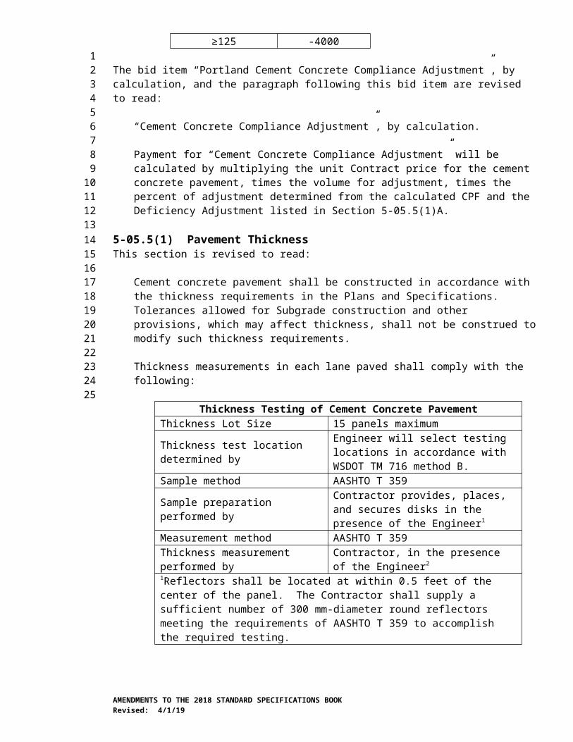
12. Stirrup Projection from Top of Girder:
Wide flange thin deck and slab girders: ½ inch
All other girders: ¾ inch
6-02.3(27) Concrete for Precast UnitsThe last sentence of the first paragraph is revised to read:
Type III portland cement or blended hydraulic cement is permitted to be used in precast concrete units.
6-02.3(28)B CastingIn the second paragraph, the reference to Section 6-02.3(25)B is revised to read Section 6-02.3(25)C.
6-02.3(28)D Contractors Control StrengthIn the first paragraph, “WSDOT FOP for AASHTO T 23” is revised to read “FOP for AASHTO T 23”.
6-02.3(28)E FinishingThis section is supplemented with the following:
The Contractor may repair defects in precast panels in accordance with Section 6-01.16.
6-03.AP6Section 6-03, Steel StructuresJanuary 7, 2019
6-03.2 MaterialsIn the first paragraph, the material reference for Paints is revised to read:
Paints and Related Materials 9-08
6-03.3(25)A3 Ultrasonic InspectionThe first paragraph (up until the colon) is revised to read:
Complete penetration groove welds on plates 5/16 inch and thicker in the following welded assemblies or Structures shall be 100 percent ultrasonically inspected:
6-03.3(33) Bolted ConnectionsThe first paragraph is supplemented with the following:
After final tightening of the fastener components, the threads of the bolts shall at a minimum be flush with the end of the nut.
The following is inserted after the third sentence of the fourth paragraph:
When galvanized bolts are specified, tension-control galvanized bolts are not permitted.
AMENDMENTS TO THE 2018 STANDARD SPECIFICATIONS BOOKRevised: 4/1/19
123456789
101112131415161718192021222324252627282930
3132333435363738394041424344454647484950

6-05.AP6Section 6-05, PilingJanuary 2, 2018
6-05.3(9)A Pile Driving Equipment ApprovalThe fourth sentence of the second paragraph is revised to read:
For prestressed concrete piles, the allowable driving stress in kips per square inch shall be 0.095 ∙√ f 'c plus prestress in tension, and 0.85f’c minus prestress in compression, where f’c is the concrete compressive strength in kips per square inch.
6-07.AP6Section 6-07, PaintingJanuary 7, 2019
6-07.1 DescriptionThe first sentence is revised to read:
This work consists of containment, surface preparation, shielding adjacent areas from work, testing and disposing of debris, furnishing and applying paint, and cleaning up after painting is completed.
6-07.2 MaterialsThe material reference for Paint is revised to read:
Paint and Related Materials 9-08
6-07.3(1)A Work Force Qualifications for Shop Application of PaintThis section is supplemented with the following new sentence:
The work force may be accepted based on the approved facility.
6-07.3(1)B Work Force Qualifications for Field Application of PaintThe first two paragraphs are revised to read:
The Contractor preparing the surface and applying the paint shall be certified under SSPC-QP 1 or NACE International Institute Contractor Accreditation Program (NIICAP) AS 1.
The Contractor removing and otherwise disturbing existing paint containing lead and other hazardous materials shall be certified under SSPC-QP 2, Category A or NIICAP AS 2.
The third paragraph (up until the colon) is revised to read:
In lieu of the above SSPC or NIICAP certifications, the Contractor performing the specified work shall complete both of the following actions:
Item number 2 of the third paragraph is revised to read:
AMENDMENTS TO THE 2018 STANDARD SPECIFICATIONS BOOKRevised: 4/1/19
1234
56789
1011121314
1516171819202122232425262728293031323334353637383940414243444546474849
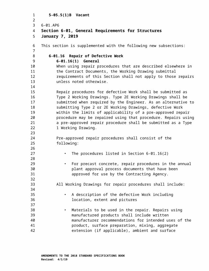
2. The Contractor’s quality control inspector(s) for the project shall be NACE-certified CIP Level 3 or SSPC Protective Coating Inspector (PCI) Level 3.
6-07.3(2) SubmittalsThe first paragraph is supplemented with the following:
Each component of the plan shall identify the specification section it represents.
6-07.3(2)B Contractor’s Quality Control Program Submittal ComponentThe numbered list in the first paragraph is revised to read:
1. Description of the inspection procedures, tools, techniques and the acceptance criteria for all phases of work.
2. Procedure for implementation of corrective action for non-conformance work.
3. The paint system manufacturer’s recommended methods of preventing defects.
4. The Contractor’s frequency of quality control inspection for each phase of work.
5. Example of each completed form(s) of the daily quality control report used to document the inspection work and tests performed by the Contractor’s quality control personnel.
6-07.3(2)C Paint System Manufacturer and Paint System Information Submittal ComponentItem number 1 is revised to read:
1. Product data sheets and Safety Data Sheets (SDS) on the paint materials, paint preparation, and paint application, as specified by the paint manufacturer, including:
a. All application instructions, including the mixing and thinning directions.
b. Recommended spray nozzles and pressures.
c. Minimum and maximum drying time between coats.
d. Restrictions on temperature and humidity.
e. Repair procedures for shop and field applied coatings.
f. Maximum dry film thickness for each coat.
g. Minimum wet film thickness for each coat to achieve the specified minimum dry film thickness.
6-07.3(2)D Hazardous Waste Containment, Collection, Testing, and Disposal Submittal ComponentThe first paragraph (up until the colon) is revised to read:
AMENDMENTS TO THE 2018 STANDARD SPECIFICATIONS BOOKRevised: 4/1/19
123456789
101112131415161718192021222324252627282930313233343536373839404142434445464748495051

The hazardous waste containment, collection, testing, and disposal shall meet all Federal and State requirements, and the submittal component of the painting plan shall include the following:
6-07.3(2)E Cleaning and Surface Preparation Submittal ComponentItem 1(b) of the first paragraph is revised to read::
b. Type, manufacturer, and brand of abrasive blast material and all associated additives, including Safety Data Sheets (SDS).
6-07.3(3)B Quality Control and Quality Assurance for Field Application of PaintThe last sentence of the first paragraph (excluding the numbered list) is revised to read:
The Contractor’s quality control operations shall include a minimum monitoring and documenting the following for each working day:
Item number 1 in the fourth paragraph is revised to read:
1. Environmental conditions for painting in accordance with ASTM E 337.
Item number 4 in the fourth paragraph is revised to read:
4. Pictorial of surface preparation guides in accordance with SSPC-VIS 1, 3, 4, and 5.
Item number 5 in the fourth paragraph is revised to read:
5. Surface profile by Keanne-Tator comparator in accordance with ASTM D 4417 and SSPC PA17.
6-07.3(4) Paint System Manufacturer’s Technical RepresentativeThis section is revised to read:
The paint system manufacturer’s representative shall be present at the jobsite for the pre-painting conference and for the first day of paint application, and shall be available to the Contractor and Contracting Agency for consultation for the full project duration.
6-07.3(5) Pre-Painting ConferenceThe second paragraph is revised to read:
If the Contractor’s key personnel change between any work operations, an additional conference shall be held if requested by the Engineer.
6-07.3(6)A Paint ContainersIn item number 2 of the first paragraph, “Federal Standard 595” is revised to read “SAE AMS Standard 595”.
6-07.3(6)B Paint StorageItem number 2 of the second paragraph is revised to read:
2. The Contractor shall monitor and document daily the paint material storage facility with a high-low recording thermometer device.
AMENDMENTS TO THE 2018 STANDARD SPECIFICATIONS BOOKRevised: 4/1/19
123456789
10111213141516171819202122232425262728293031323334353637383940414243444546474849505152

6-07.3(7) Paint Sampling and TestingThe first two paragraphs are revised to read:
The Contractor shall provide the Engineer 1 quart of each paint representing each lot. Samples shall be accompanied with a Safety Data Sheet.
If the quantity of paint required for each component of the paint system for the entire project is 20 gallons or less, then the paint system components will be accepted as specified in Section 9-08.1(7).
6-07.3(8)A Paint Film Thickness Measurement GagesThe first paragraph is revised to read:
Paint dry film thickness measurements shall be performed with either a Type 1 pull-off gage or a Type 2 electronic gage as specified in SSPC Paint Application Specification No. 2, Procedure for Determining Conformance to Dry Coating Thickness Requirements.
6-07.3(9) Painting New Steel StructuresThe last sentence of the second paragraph is revised to read:
Welded shear connectors are not required to painted.
The last paragraph is revised to read:
Temporary attachments or supports for scaffolding, containment or forms shall not damage the paint system.
6-07.3(9)A Paint SystemThe first paragraph is revised to read:
The paint system applied to new steel surfaces shall consist of the following:
Option 1 (component based paint system):
Primer Coat – Inorganic Zinc Rich 9-08.1(2)CIntermediate Coat – Moisture Cured Polyurethane 9-08.1(2)GIntermediate Stripe Coat – Moisture Cured Polyurethane 9-08.1(2)GTop Coat – Moisture Cured Polyurethane 9-08.1(2)H
Option 2 (performance based paint system):
Primer Coat – Inorganic Zinc Rich 9-08.1(2)MIntermediate Coat – Epoxy 9-08.1(2)MIntermediate Stripe Coat – Epoxy 9-08.1(2)MTop Coat – Polyurethane 9-08.1(2)M
The following new paragraph is inserted after the first paragraph:
Paints and related materials shall be products listed in the current WSDOT Qualified Products List (QPL). Component based paint systems shall be listed on the QPL in the applicable sections of Section 9-08. Performance based systems shall be listed on the
AMENDMENTS TO THE 2018 STANDARD SPECIFICATIONS BOOKRevised: 4/1/19
123456789
10111213141516171819202122232425262728293031323334353637383940414243444546474849505152

current Northeast Protective Coatings Committee (NEPCOAT) Qualified Products List “A” as listed on the WSDOT QPL in Section 9-08.1(2)M. If the paint and related materials for the component based system is not listed in the current WSDOT QPL, a sample shall be submitted to the State Materials Laboratory in Tumwater for evaluation and acceptance in accordance with Section 9-08.
6-07.3(9)C Mixing and Thinning PaintThis section is revised to read:
The Contractor shall thoroughly mix paint in accordance with the manufacturer’s written recommendations and by mechanical means to ensure a uniform and lump free composition. Paint shall not be mixed by means of air stream bubbling or boxing. Paint shall be mixed in the original containers and mixing shall continue until all pigment or metallic powder is in suspension. Care shall be taken to ensure that the solid material that has settled to the bottom of the container is thoroughly dispersed. After mixing, the Contractor shall inspect the paint for uniformity and to ensure that no unmixed pigment or lumps are present.
Catalysts, curing agents, hardeners, initiators, or dry metallic powders that are packaged separately may be added to the base paint in accordance with the paint manufacturer’s written recommendations and only after the paint is thoroughly mixed to achieve a uniform mixture with all particles wetted. The Contractor shall then add the proper volume of curing agent to the correct volume of base and mix thoroughly. The mixture shall be used within the pot life specified by the manufacturer. Unused portions shall be discarded at the end of each work day. Accelerants are not permitted except as allowed by the Engineer.
The Contractor shall not add additional thinner at the application site except as allowed by the Engineer. The amount and type of thinner, if allowed, shall conform to the manufacturer’s specifications. If recommended by the manufacturer and allowed by the Engineer, a measuring cup shall be used for the addition of thinner to any paint with graduations in ounces. No un-measured addition of thinner to paint will be allowed. Any paint found to be thinned by unacceptable methods will be rejected.
When recommended by the manufacturer, the Contractor shall constantly agitate paint during application by use of paint pots equipped with mechanical agitators.
The Contractor shall strain all paint after mixing to remove undesirable matter, but without removing the pigment or metallic powder.
Paint shall be stored and mixed in a secure, contained location to eliminate the potential for spills into State waters and onto the ground and highway surfaces.
6-07.3(9)D Coating ThicknessThis section is revised to read:
Dry film thickness shall be measured in accordance with SSPC Paint Application Specification No. 2, Procedure for Determining Conformance to Dry Coating Thickness Requirements.
The minimum dry film thickness of the primer coat shall not be less than 2.5 mils.
AMENDMENTS TO THE 2018 STANDARD SPECIFICATIONS BOOKRevised: 4/1/19
123456789
10111213141516171819202122232425262728293031323334353637383940414243444546474849505152
The minimum dry film thickness of each coat (combination of intermediate and intermediate stripe, and top) shall be not less than 3.0 mils.
The dry film thickness of each coat shall not be thicker than the paint manufacturer’s recommended maximum thickness.
The minimum wet film thickness of each coat shall be specified by the paint manufacturer to achieve the minimum dry film thickness.
Film thickness, wet and dry, will be measured by gages conforming to Section 6-07.3(8)A.
Wet measurements will be taken immediately after the paint is applied in accordance with ASTM D4414. Dry measurements will be taken after the coating is dry and hard in accordance with SSPC Paint Application Specification No. 2.
Each painter shall be equipped with wet film thickness gages and shall be responsible for performing frequent checks of the paint film thickness throughout application.
Coating thickness measurements may be made by the Engineer after the application of each coat and before the application of the succeeding coat. In addition, the Engineer may inspect for uniform and complete coverage and appearance. One hundred percent of all thickness measurements shall meet or exceed the minimum wet film thickness. In areas where wet film thickness measurements are impractical, dry film thickness measurements may be made. If a question arises about an individual coat’s thickness or coverage, it may be verified by the use of a Tooke gage in accordance with ASTM D4138.
If the specified number of coats does not produce a combined dry film thickness of at least the sum of the thicknesses required per coat, if an individual coat does not meet the minimum thickness, or if visual inspection shows incomplete coverage, the coating system will be rejected and the Contractor shall discontinue painting and surface preparation operations and shall submit a Type 2 Working Drawing of the repair proposal. The repair proposal shall include documentation demonstrating the cause of the less-than-minimum thickness, along with physical test results, as necessary, and modifications to Work methods to prevent similar results. The Contractor shall not resume painting or surface preparation operations until receiving the Engineer’s acceptance of the completed repair.
6-07.3(9)E Surface Temperature Requirements Prior to Application of PaintThis section, including title, is revised to read:
6-07.3(9)E Environmental Condition Requirements Prior to Application of PaintPaint shall be applied only during periods when:
1. Air and steel temperatures are in accordance with the paint manufacturer’s recommendations but in no case less than 35°F nor greater than 115°F.
2. Steel surface temperature is a minimum of 5°F above the dew point.
3. Steel surface is not wet.
AMENDMENTS TO THE 2018 STANDARD SPECIFICATIONS BOOKRevised: 4/1/19
123456789
10111213141516171819202122232425262728293031323334353637383940414243444546474849505152
4. Relative humidity is within the manufacturer’s recommended range.
5. The anticipated ambient temperature will remain above 35°F or the manufacturer’s minimum temperature, whichever is greater, during the paint drying and curing period.
Application will not be allowed if conditions are not favorable for proper application and performance of the paint.
Paint shall not be applied when weather conditions are unfavorable to proper curing. If a paint system manufacturer’s recommendations allow for application of a paint under environmental conditions other than those specified, the Contractor shall submit a Type 2 Working Drawing consisting of a letter from the paint manufacturer specifying the environmental conditions under which the paint can be applied. Application of paint under environmental conditions other than those specified in this section will not be allowed without the Engineer’s concurrence.
6-07.3(9)F Shop Surface Cleaning and PreparationThe last sentence is revised to read:
The entire steel surface to be painted, including surfaces specified in Section 6-07.3(9)G to receive a mist coat of primer, shall be cleaned to a near white condition in accordance with SSPC-SP 10, Near-white Metal Blast Cleaning, and shall be in this condition immediately prior to paint application.
6-07.3(9)G Application of Shop Primer CoatThe first paragraph is supplemented with the following:
Repairs of the shop primer coat shall be prepared in accordance with the painting plan. Shop primer coat repair paint shall be selected from the approved component based or performance based paint system in accordance with Section 6-07.3(10)H.
6-07.3(9)H Containment for Field CoatingThis section is revised to read:
The Contractor shall use a containment system in accordance with Section 6-07.3(10)A for surface preparation and prime coating of all uncoated areas remaining, including bolts, nuts, washers, and splice plates.
During painting operations of the intermediate, stripe and top coats the Contractor shall furnish, install, and maintain drip tarps below the areas to be painted to contain all spilled paint, buckets, brushes, and other deleterious material, and prevent such materials from reaching the environment below or adjacent to the structure being painted. Drip tarps shall be absorbent material and hung to minimize puddling. The Contractor shall evaluate the project-specific conditions to determine the specific type and extent of containment needed to control the paint emissions and shall submit a containment plan in accordance with Section 6-07.3(2).
6-07.3(9)I Application of Field CoatingsThis section is revised to read:
AMENDMENTS TO THE 2018 STANDARD SPECIFICATIONS BOOKRevised: 4/1/19
123456789
10111213141516171819202122232425262728293031323334353637383940414243444546474849505152
An on-site supervisor shall be present for each work shift at the bridge site.
Upon completion of erection Work, all uncoated or damaged areas remaining, including bolts, nuts, washers, and splice plates, shall be prepared in accordance with Section 6-07.3(9)F, followed by a field primer coat of a zinc-rich primer and final coats of paint selected from the approved component or performance based paint system in accordance with Section 6-07.3(10)H. . The intermediate, intermediate stripe, and top coats shall be applied in accordance with the manufacturer’s written recommendations.
Upon completion of erection Work, welds for steel column jackets may be prepared in accordance with SSPC-SP 15, Commercial Grade Power Tool Cleaning.
The minimum drying time between coats shall be as shown in the product data sheets, but not less than 12 hours. The Contractor shall determine whether the paint has cured sufficiently for proper application of succeeding coats.
The maximum time between intermediate and top coats shall be in accordance with the manufacturer’s written recommendations. If the maximum time between coats is exceeded, all newly coated surfaces shall be prepared to SSPC-SP 7, Brush-off Blast Cleaning, and shall be repainted with the same paint that was cleaned, at no additional cost to the Contracting Agency.
Each coat shall be applied in a uniform layer, completely covering the preceding coat. The Contractor shall correct runs, sags, skips, or other deficiencies before application of succeeding coats. Such corrective work may require re-cleaning, application of additional paint, or other means as determined by the Engineer, at no additional cost to the Contracting Agency.
Dry film thickness measurements will be made in accordance with Section 6-07.3(9)D.
All paint damage that occurs shall be repaired in accordance with the manufacturer’s written recommendations. On bare areas or areas of insufficient primer thickness, the repair shall include field-applied zinc-rich primer and the final coats of paint selected from the approved component or performance based paint system in accordance with Section 6-07.3(10)H. On areas where the primer is at least equal to the minimum required dry film thickness, the repair shall include the application of the final two coats of the paint system. All paint repair operations shall be performed by the Contractor at no additional cost or time to the Contracting Agency.
6-07.3(10)A ContainmentThe first sentence of the third paragraph is revised to read:
Emissions shall be assessed by Visible Emission Observations (Method A) in SSPC Technology Update No. 7, Conducting Ambient Air, Soil, and Water Sampling of Surface Preparation and Paint Disturbance Activities, Section 6.2 and shall be limited to the Level A Acceptance Criteria Option Level 0 Emissions standard.
6-07.3(10)D Surface Preparation Prior to Overcoat PaintingThe first paragraph is revised to read:
The Contractor shall remove any visible oil, grease, and road tar in accordance with SSPC-SP 1, Solvent Cleaning.
AMENDMENTS TO THE 2018 STANDARD SPECIFICATIONS BOOKRevised: 4/1/19
123456789
10111213141516171819202122232425262728293031323334353637383940414243444546474849505152

The second paragraph is revised to read:
Following any preparation by SSPC-SP1, all steel surfaces to be painted shall be prepared in accordance with SSPC-SP 7, Brush-off Blast Cleaning. Surfaces inaccessible to brush-off blast shall be prepared in accordance with SSPC-SP 3, Power Tool Cleaning, as allowed by the Engineer.
The first sentence of the third paragraph is revised to read:
Following brush-off blast cleaning, the Contractor shall perform spot abrasive blast cleaning in accordance with SSPC-SP 6, Commercial Blast Cleaning.
The second to last sentence of the third paragraph is revised to read:
For small areas, as allowed by the Engineer, the Contractor may substitute cleaning in accordance with SSPC-SP 15, Commercial Grade Power Tool Cleaning.
6-07.3(10)G Treatment of Pack and Rust GapsThe second paragraph is revised to read:
Pack rust forming a gap between steel surfaces of ⅟16 to ¼ inch shall be cleaned to a depth of at least one half of the gap width. The gaps shall be cleaned and prepared in accordance with SSPC-SP6. The cleaned gap shall be treated with rust penetrating sealer, prime coated, and then caulked to form a watertight seal along the top edge and the two sides of the steel pieces involved, using the rust penetrating sealer and caulk as accepted by the Engineer. The bottom edge or lowest edge of the steel pieces involved shall not be caulked.
The third paragraph is supplemented with the following:
Caulk shall be a single-component urethane sealant conforming to Section 9-08.7.
The fifth paragraph is revised to read:
At locations where gaps between steel surfaces exceed ¼ inch, the Contractor shall clean and prepare the gap in accordance SSPC-SP6, apply the rust penetrating sealer, apply the prime coat, and then fill the gap with foam backer rod material as accepted by the Engineer. The foam backer rod material shall be of sufficient diameter to fill the crevice or gap. The Contractor shall apply caulk over the foam backer rod material to form a watertight seal.
This section is supplemented with the following new paragraph:
Caulk and backer rod, if needed, shall be placed prior to applying the top coat. The Contractor, with the concurrence of the Engineer, may apply the rust penetrating sealer after application of the prime coat provided the primer is removed in the areas to be sealed. The areas to be sealed shall be re-cleaned and re-prepared in accordance with SSPC-SP6.
6-07.3(10)H Paint SystemThe first paragraph is revised to read:
AMENDMENTS TO THE 2018 STANDARD SPECIFICATIONS BOOKRevised: 4/1/19
123456789
10111213141516171819202122232425262728293031323334353637383940414243444546474849505152

The paint system applied to existing steel surfaces shall consist of the following five-coat system:
Option 1 (component based system):
Primer Coat – Zinc-filled Moisture Cured Polyurethane 9-08.1(2)FPrimer Stripe Coat - Moisture Cured Polyurethane 9-08.1(2)FIntermediate Coat - Moisture Cured Polyurethane 9-08.1(2)GIntermediate Stripe Coat - Moisture Cured Polyurethane 9-08.1(2)GTop Coat - Moisture Cured Polyurethane 9-08.1(2)H
Option 2 (performance based system):
Primer Coat – Zinc-rich Epoxy 9-08.1(2)NPrimer Stripe Coat – Epoxy 9-08.1(2)NIntermediate Coat – Epoxy 9-08.1(2)NIntermediate Stripe Coat – Epoxy 9-08.1(2)NTop Coat – Polyurethane 9-08.1(2)N
The following new paragraph is inserted after the first paragraph:
Paints and related materials shall be a product listed in the current WSDOT Qualified Products List (QPL). Component based paint systems shall be listed on the QPL in the applicable sections of Section 9-08. Performance based systems shall be listed on the current Northeast Protective Coatings Committee (NEPCOAT) Qualified Products List “B” as listed on the WSDOT QPL in Section 9-08.1(2)N. If the paint and related material for the component based system is not listed in the current WSDOT QPL, a sample shall be submitted to the State Materials Laboratory in Tumwater for evaluation and acceptance in accordance with Section 9-08.
6-07.3(10)J Mixing and Thinning PaintThis section is revised to read:
Mixing and thinning paint shall be in accordance with Section 6-07.3(9)C.
6-07.3(10)K Coating ThicknessThis section is revised to read:
Coating thickness shall be in accordance with Section 6-07.3(9)D except the minimum dry film thickness of each coat (combination of primer and primer stripe, combination of intermediate and intermediate stripe, and top) shall not be less than 3.0 mils.
6-07.3(10)L Environmental Condition Requirements Prior to Application of PaintThis section is revised to read:
Environmental conditions shall be in accordance with Section 6-07.3(9)E.
6-07.3(10)M Steel Surface Condition Requirements Prior to Application of PaintThe third paragraph is revised to read:
AMENDMENTS TO THE 2018 STANDARD SPECIFICATIONS BOOKRevised: 4/1/19
123456789
10111213141516171819202122232425262728293031323334353637383940414243444546474849505152
Edges of existing paint shall be feathered in accordance with SSPC-PA 1, Shop, Field, and Maintenance Coating of Metals, Note 15.20.
6-07.3(10)N Field Coating Application MethodsThe third sentence is revised to read:
The Contractor may apply stripe coat paint using spray or brush but shall follow spray application using a brush to ensure complete coverage around structural geometric irregularities and to push the paint into gaps between existing steel surfaces and around rivets and bolts.
6-07.3(10)O Applying Field CoatingsThe second to last paragraph is revised to read:
Each application of primer, primer stripe, intermediate, intermediate stripe, and top coat shall be considered as separately applied coats. The Contractor shall not use a preceding or subsequent coat to remedy a deficiency in another coat. The Contractor shall apply the top coat to at least the minimum specified top coat thickness, to provide a uniform appearance and consistent finish coverage.
6-07.3(10)P Field Coating RepairThe second sentence is revised to read:
Repair areas shall be cleaned of all damaged paint and the system reapplied using all coats typical to the paint system and shall meet the minimum coating thickness.
6-07.3(11)A Painting of Galvanized SurfacesThis section is revised to read:
All galvanized surfaces receiving paint shall be prepared for painting in accordance with the ASTM D 6386. The method of preparation shall be brush-off in accordance with SSPC-SP16 Brush-Off Blast Cleaning of Coated and Uncoated Galvanized Steel, Stainless Steels, and Non-Ferrous Metals or as otherwise allowed by the Engineer. The Contractor shall not begin painting until receiving the Engineer’s acceptance of the prepared galvanized surface. For galvanized bolts used for replacement of deteriorated existing rivets, the Contractor, with the concurrence of the Engineer and after successful demonstration testing, may prepare galvanized surfaces in accordance with SSPC-SP1 followed by SSPC-SP2, Hand Tool Cleaning or SSPC-SP3, Power Tool Cleaning. The demonstration testing shall include adhesion testing of the first coat of paint over galvanized bolts, nuts, and washers or a representative galvanized surface. Adhesion testing shall be performed in accordance with ASTM D 4541 for 600 psi minimum adhesion. A minimum of 3 successful tests shall be performed on the galvanized surface prepared and painted using the same methods and materials to be used on the galvanized bolts, nuts and washers in the field.
6-07.3(11)A2 Paint Coat MaterialsThis section is revised to read:
The Contractor shall paint the dry surface as follows:
AMENDMENTS TO THE 2018 STANDARD SPECIFICATIONS BOOKRevised: 4/1/19
123456789
1011121314151617181920212223242526272829303132333435363738394041424344454647484950
1. The first coat over a galvanized surface shall be an epoxy polyamide conforming to Section 9-08.1(2)E . In the case of galvanized bolts used for replacement of deteriorated existing rivets and for small surface areas less than or equal to one square foot, an intermediate moisture cured polyurethane conforming to Section 9-08.1(2)G may be used as a first coat. In both cases the first coat shall be compatible with galvanizing and as recommended by the top coat manufacturer.
2. The second coat shall be a top coat moisture cured aliphatic polyurethane conforming to Section 9-08.1(2)H or a top coat polyurethane conforming to Section 6-07.3(10)H Option 2 NEPCOAT performance based paint specification compatible with the first coat as recommended by the manufacturer.
Each coat shall be dry before the next coat is applied. All coats applied in the shop shall be dried hard before shipment.
6-07.3(11)B Powder Coating of Galvanized SurfacesThis section is revised to read:
Powder coating of galvanized surfaces shall consist of the following coats:
1. The first coat shall be an epoxy powder primer coat conforming to Section 9-08.2.
2. The second coat shall be a polyester finish coat conforming to Section 9-08.2.
6-07.3(11)B3 Galvanized Surface Cleaning and PreparationThe first three paragraphs are revised to read:
Galvanized surfaces receiving the powder coating shall be cleaned and prepared for coating in accordance with ASTM D 7803, and the project-specific powder coating plan.
Assemblies conforming to the ASTM D 7803 definition for newly galvanized steel shall receive surface smoothing and surface cleaning in accordance with ASTM D 7803, Section 5, and surface preparation in accordance with ASTM D 7803, Section 5.1.3.
Assemblies conforming to the ASTM D 7803 definition for partially weathered galvanized steel shall be checked and prepared in accordance with ASTM D 7803, Section 6, before then receiving surface smoothing and surface cleaning in accordance with ASTM D 7803, Section 5, and surface preparation in accordance with ASTM D 7803, Section 5.1.3.
The fourth paragraph (up until the colon) is revised to read:
Assemblies conforming to the ASTM D 7803 definition for weathered galvanized steel shall be prepared in accordance with ASTM D 7803, Section 7 before then receiving surface smoothing and surface cleaning in accordance with ASTM D 7803, Section 5, and surface preparation in accordance with ASTM D 7803, Section 5.3 except as follows:
AMENDMENTS TO THE 2018 STANDARD SPECIFICATIONS BOOKRevised: 4/1/19
123456789
101112131415161718192021222324252627282930313233343536373839404142434445464748495051

6-07.3(11)B5 TestingItem number 4 in the first paragraph is revised to read:
4. Adhesion testing in accordance with ASTM D 4541 for 600 psi minimum adhesion for the complete two-component system.
The second sentence of the fourth paragraph is revised to read:
Rejected assemblies shall be repaired or recoated by the Contractor, at no additional expense to the Contracting Agency, in accordance with the powder coating manufacturer’s recommendation as detailed in the project-specific powder coating plan, until the assemblies satisfy the acceptance testing requirements.
6-07.3(12) Painting Ferry Terminal StructuresThis section is revised to read:
Painting of ferry terminal Structures shall be in accordance with Section 6-07.3 as supplemented below.
This section is supplemented with the following new subsections:
6-07.3(12)A Painting New Steel Ferry Terminal StructuresPainting of new steel Structures shall be in accordance with Section 6-07.3(9) except that all coatings (primer, intermediate, intermediate stripe, and top) shall be applied in the shop with the following exceptions:
1. Steel surfaces to be field welded.
2. Steel surfaces to be greased.
3. The length of piles designated in the Plans not requiring painting.
The minimum drying time between coats shall be as shown in the product data sheets, but not less than 12 hours. The Contractor shall determine whether the paint has cured sufficiently for proper application of succeeding coats.
6-07.3(12)A1 Paint SystemsPaint systems for Structural Steel, which includes vehicle transfer spans and towers, pedestrian overhead loading structures and towers, upland structural steel and other elements as designated in the Special Provisions shall be as specified in Section 6-07.3(9)A.
Paint systems for Piling, Landing Aids and Life Ladders shall be as specified in the Special Provisions.
6-07.3(12)A2 Paint ColorPaint colors shall be as specified in the Special Provisions.
6-07.3(12)A3 Coating ThicknessCoating thicknesses shall be as specified in the Special Provisions.
AMENDMENTS TO THE 2018 STANDARD SPECIFICATIONS BOOKRevised: 4/1/19
123456789
101112131415161718192021222324252627282930313233343536373839404142434445464748495051
6-07.3(12)A4 Application of Field CoatingsAn on-site supervisor shall be present for each work shift at the project site.
Upon completion of erection Work, all uncoated or damaged areas remaining, including bolts, nuts, washers, splice plates, and field welds shall be prepared in accordance with SSPC-SP 1, Solvent Cleaning, followed by SSPC-SP 11, Power Tool Cleaning to Bare Metal. Surface preparation shall be measured according to SSPC-VIS 3. SSPC-SP 11 shall be performed for a minimum distance of 1 inch from the uncoated or damaged area. In addition, intact shop-applied coating surrounding the area shall be abraded or sanded for a distance of 6 inches out from the properly prepared clean/bare metal areas to provide adequate roughness for application of field coatings. All sanding dust and contamination shall be removed prior to application of field coatings.
Field applied paint for Structural Steel shall conform to Section 6-07.3(10)H, as applicable. Field applied paint for Piling, Landing Aids and Life Ladders shall be as specified in the Special Provisions.
For areas above the tidal zone, the minimum drying time between coats shall be as shown in the product data sheets, but not less than 12 hours. For areas within the tidal zone, the minimum drying time between coats shall be as recommended by the paint system manufacturer. The Contractor shall determine whether the paint has cured sufficiently for proper application of succeeding coats.
The maximum time between intermediate and top coats shall be in accordance with the manufacturer’s written recommendations. If the maximum time between coats is exceeded, all newly coated surfaces shall be prepared to SSPC-SP 3, Power Tool Cleaning, and shall be repainted with the same paint that was cleaned, at no additional cost to the Contracting Agency.
Each coat shall be applied in a uniform layer, completely covering the preceding coat. The Contractor shall correct runs, sags, skips, or other deficiencies before application of succeeding coats. Such corrective work may require re-cleaning, application of additional paint, or other means as determined by the Engineer, at no additional cost to the Contracting Agency.
Surface preparation for underwater locations shall consist of removing all dirt, oil, grease, loose paint, loose rust, and marine growth from the area that is to be repaired. The sound paint surrounding the damaged area shall be roughened to meet the requirements of the manufacturer. Paint for underwater applications shall be as specified in the Special Provisions and shall be applied in accordance with the manufacturer’s recommendations.
6-07.3(12)B Painting Existing Steel Ferry Terminal StructuresPainting of existing steel structures shall be in accordance with Section 6-07.3(10) as supplemented by the following.
6-07.3(12)B1 ContainmentContainment for full removal shall be in accordance with Section 6-07.3(10)A. Containment for overcoat systems shall be in accordance with all applicable Permits as required in the Special Provisions.
AMENDMENTS TO THE 2018 STANDARD SPECIFICATIONS BOOKRevised: 4/1/19
123456789
10111213141516171819202122232425262728293031323334353637383940414243444546474849505152

Prior to cleaning the Contractor shall enclose all exposed electrical and mechanical equipment to seal out dust, water, and paint. Non-metallic surfaces shall not be abrasive blasted or painted. Unless otherwise specified, the following metallic surfaces shall not be painted and shall be protected from abrasive blasting and painting:
1. Galvanized and stainless steel surfaces not previously painted,
2. Non-skid surfaces,
3. Unpainted intentionally greased surfaces,
4. Equipment labels, identification plates, tags, etc.,
5. Fire and emergency containers or boxes,
6. Mechanical hardware such as hoist sheaves, hydraulic cylinders, gear boxes, wire rope, etc.
The Contractor shall submit a Type 2 Working Drawing consisting of materials and equipment used to shield components specified to not be cleaned and painted.The Contractor shall shut off the power prior to working around electrical equipment. The Contractor shall follow the lock-out/tag-out safety provisions of the WAC 296-803 and all other applicable safety standards.
6-07.3(12)B2 Surface PreparationFor applications above high water and within the tidal zone, surface preparation for overcoat painting shall be in accordance with SSPC-SP 1, Solvent Cleaning, followed by SSPC-SP 3, Power Tool Cleaning. Use of wire brushes is not allowed. After SP 3 cleaning has been completed all surfaces exhibiting coating failure down to the steel substrate, and those exhibiting visible corrosion, shall be prepared down to clean bare steel in accordance with SSPC-SP 15, Commercial Grade Power Tool Cleaning. Surface preparation shall be measured according to SSPC-VIS 3. SSPC-SP 15 shall be performed for a minimum distance of 1 inch from the area exhibiting failure or visible corrosion. In addition, intact shop-applied coating surrounding the repair area shall be abraded or sanded for a distance of 6 inches out from the properly prepared clean/bare metal areas to provide adequate roughness for application of repair coatings. All sanding dust and contamination shall be removed prior to application of repair coatings. Surface preparation for full paint removal shall be in accordance with Section 6-07.3(10)E except SSPC-SP 11 will be permitted as detailed in the Contractor’s painting plan and as allowed by the Engineer.
Surface preparation for underwater locations shall consist of removing all dirt, oil, grease, loose paint, loose rust, and marine growth from the area that is to be repaired. The sound paint surrounding the damaged area shall be roughened as required by the coating manufacturer.
Removed marine growth may be released to state waters provided the marine growth is not mixed with contaminants (paint, oil, rust, etc.) and it shall not accumulate on the sea bed. All marine growth containing contaminants shall be collected for proper disposal.
AMENDMENTS TO THE 2018 STANDARD SPECIFICATIONS BOOKRevised: 4/1/19
123456789
10111213141516171819202122232425262728293031323334353637383940414243444546474849505152
Surface preparation for the underside of bridge decks (consisting of either a steel grid system of main bars or tees and a light gauge metal form, in-filled with concrete or a corrugated light gauge metal form, infilled with concrete) shall be in accordance with SSPC-SP 2, Hand Tool Cleaning or SSPC-SP 3, Power Tool Cleaning with the intent of not causing further damage to the light gauge metal form. Following removal of any pack rust and corroded sections from the underside of the bridge deck, cleaning and flushing to remove salts and prior to applying the primer coat, the Contractor shall seal the entire underside of the deck system with rust-penetrating sealer. Damage to galvanized metal forms and/or grids shall be repaired in accordance with ASTM A 780, with the preferred method of repair using paints containing zinc dust.
6-07.3(12)B3 Paint SystemsPaints systems for Structural Steel, which includes vehicle transfer spans and towers, pedestrian overhead loading structures and towers, upland structural steel and other elements as designated in the Special Provisions shall be as specified in Section 6-07.3(10)H.
Paint systems for Piling, Landing Aids, Life Ladders, underside of vehicle transfer span bridge decks, non-skid surface treated areas, and anti-graffiti coatings shall be as specified in the Special Provisions.
6-07.3(12)B4 Paint ColorPaint colors shall be as specified in the Special Provisions.
6-07.3(12)B5 Coating ThicknessCoating thicknesses shall be as specified in the Special Provisions.
6-07.3(12)B6 Application of Field CoatingsApplication of field coatings shall be in accordance with Section 6-07.3(10)O and Section 6-07.3(12)A2 except for the following:
1. All coatings applied in the field shall be applied using a brush or roller. Spray application methods may be used if allowed by the Engineer.
2. Applied coatings shall not be immersed until the coating has been cured as required by the coating manufacturer.
3. Non-skid surface treatment products shall be applied in accordance with the manufacturer’s recommendations.
4. Anti-graffiti coatings shall be applied in one coat following application of the top coat, where specified in the Plans.
6-07.3(14)B Reference StandardsThe second standard reference (to SSPC CS 23.00), and its accompanying title, is revised to read:
SSPC CS 23.00 Specification for the Application of Thermal Spray Coatings (Metallizing) of Aluminum, Zinc, and Their Alloys and Composites for the Corrosion Protection of Steel
AMENDMENTS TO THE 2018 STANDARD SPECIFICATIONS BOOKRevised: 4/1/19
123456789
10111213141516171819202122232425262728293031323334353637383940414243444546474849505152
6-08.AP6Section 6-08, Bituminous Surfacing on Structure DecksJanuary 7, 2019
6-08.3(7)A Concrete Deck PreparationThe first sentence of the first paragraph is revised to read:
The Contractor, with the Engineer, shall inspect the exposed concrete deck to establish the extent of bridge deck repair in accordance with Section 6-09.3(6).
6-08.3(8)A Structure Deck PreparationThe second sentence of the last paragraph is revised to read:
Prior to applying the primer or sheet membrane, all dust and loose material shall be removed from the Structure Deck.
6-09.AP6Section 6-09, Modified Concrete OverlaysJanuary 7, 2019
6-09.3 Construction RequirementsThis section is supplemented with the following new subsection:
6-09.3(15) Sealing and Texturing Concrete OverlayAfter the requirements for checking for bond have been met, all joints and visible cracks shall be filled and sealed with a high molecular weight methacrylate resin (HMWM). Cracks 1⁄16 inch and greater in width shall receive two applications of HMWM. Immediately following the application of HMWM, the wetted surface shall be coated with sand for abrasive finish.
After all cracks have been filled and sealed and the HMWM resin has cured, the concrete overlay surface shall receive a longitudinally sawn texture in accordance with Section 6-02.3(10)D5.
Traffic shall not be permitted on the finished concrete until it has reached a minimum compressive strength of 3,000 psi as verified by rebound number determined in accordance with ASTM C805 and the longitudinally sawn texture is completed.
6-09.3(1)B Rotary Milling MachinesThis section is revised to read:
Rotary milling machines used to remove an upper layer of existing concrete overlay, when present, shall have a maximum operating weight of 50,000 pounds and conform to Section 6-08.3(5)B.
6-09.3(1)C Hydro-Demolition MachinesThe first sentence of this section is revised to read:
Hydro-demolition machines shall consist of filtering and pumping units operating in conjunction with a remote-controlled robotic device, using high-velocity water jets to
AMENDMENTS TO THE 2018 STANDARD SPECIFICATIONS BOOKRevised: 4/1/19
1234
56789
10111213141516171819
202122232425262728293031323334353637383940414243444546474849
remove sound concrete to the nominal scarification depth shown in the Plans with a single pass of the machine, and with the simultaneous removal of deteriorated concrete.
6-09.3(1)D Shot Blasting MachinesThis section, including title, is revised to read:
6-09.3(1)D Vacant
6-09.3(1)E Air CompressorThis section is revised to read:
Air compressors shall be equipped with oil traps to eliminate oil from being blown onto the bridge deck.
6-09.3(1)J Finishing MachineThis section is revised to read:
The finishing machine shall meet the requirements of Section 6-02.3(10) and the following requirements:
The finishing machine shall be equipped with augers, followed by an oscillating, vibrating screed, vibrating roller tamper, or a vibrating pan, followed by a rotating cylindrical double drum screed. The vibrating screed, roller tamper or pan shall be of sufficient length and width to properly consolidate the mixture. The vibrating frequency of the vibrating screed, roller tamper or pan shall be variable with positive control.
6-09.3(2) SubmittalsItem number 1 and 2 are revised to read:
1. A Type 1 Working Drawing consisting of catalog cuts and operating parameters of the hydro-demolition machine selected by the Contractor for use in this project to scarify concrete surfaces.
2. A Type 1 Working Drawing consisting of catalog cuts, operating parameters, axle loads, and axle spacing of the rotary milling machine (if used to remove an upper layer of existing concrete overlay when present).
The first sentence of item number 3 is revised to read:
A Type 2 Working Drawing of the Runoff Water Disposal Plan.
6-09.3(5)A GeneralThe first sentence of the fourth paragraph is revised to read:
All areas of the deck that are inaccessible to the selected scarifying machine shall be scarified to remove the concrete surface matrix to a maximum nominal scarification depth shown in the Plans by a method acceptable to the Engineer.
This section is supplemented with the following:
AMENDMENTS TO THE 2018 STANDARD SPECIFICATIONS BOOKRevised: 4/1/19
123456789
101112131415161718192021222324252627282930313233343536373839404142434445464748495051

Concrete process water generated by scarifying concrete surface and removing existing concrete overlay operations shall be contained, collected, and disposed of in accordance with Section 5-01.3(11) and Section 6-09.3(5)C, and the Section 6-09.3(2) Runoff Water Disposal Plan.
6-09.3(5)B Testing of Hydro-Demolition and Shot Blasting MachinesThis section’s title is revised to read:
Testing of Hydro-Demolition Machines
The second paragraph is revised to read:
In the “sound” area of concrete, the equipment shall be programmed to remove concrete to the nominal scarification depth shown in the Plans with a single pass of the machine.
6-09.3(5)D Shot BlastingThis section, including title, is revised to read:
6-09.3(5)D Vacant
6-09.3(5)E RotomillingThis section, including title, is revised to read:
6-09.3(5)E Removing Existing Concrete Overlay Layer by RotomillingWhen the Contractor elects to remove the upper layer of existing concrete overlay, when present, by rotomilling prior to final scarifying, the entire concrete surface of the bridge deck shall be milled to remove the surface matrix to the depth specified in the Plans with a tolerance as specified in Section 6-08.3(5)B. The operating parameters of the rotary milling machine shall be monitored in order to prevent the unnecessary removal of concrete below the specified removal depth.
6-09.3(6) Further Deck PreparationThe first paragraph is revised to read::
Once the lane or strip being overlaid has been cleaned of debris from scarifying, the Contractor, with the Engineer, shall perform a visual inspection of the scarified surface. The Contractor shall mark those areas of the existing bridge deck that are authorized by the Engineer for further deck preparation by the Contractor.
Item number 4 of the second paragraph is deleted.
The first sentence of the third paragraph is deleted.
6-09.3(6)A Equipment for Further Deck PreparationThis section is revised to read:
Further deck preparation shall be performed using either power driven hand tools conforming to Section 6-09.3(1)A, or hydro-demolition machines conforming to Section 6-09.3(1)C.
AMENDMENTS TO THE 2018 STANDARD SPECIFICATIONS BOOKRevised: 4/1/19
123456789
101112131415161718192021222324252627282930313233343536373839404142434445464748495051
6-09.3(6)B Deck Repair PreparationThe second paragraph is deleted.
The last sentence of the second paragraph (after the preceding Amendment is applied) is revised to read:
In no case shall the depth of a sawn vertical cut exceed ¾ inch or to the top of the top steel reinforcing bars, whichever is less.
The first sentence of the third to last paragraph is revised to read:
Where existing steel reinforcing bars inside deck repair areas show deterioration greater than 20-percent section loss, the Contractor shall furnish and place steel reinforcing bars alongside the deteriorated bars in accordance with the details shown in the Standard Plans.
The last paragraph is deleted.
6-09.3(7) Surface Preparation for Concrete OverlayThe first seven paragraphs are deleted and replaced with the following:
Following the completion of any required further deck preparation the entire lane or strip being overlaid shall be cleaned to be free from oil and grease, rust and other foreign material that may still be present. These materials shall be removed by detergent-cleaning or other method accepted by the Engineer followed by sandblasting.
After detergent cleaning and sandblasting is completed, the entire lane or strip being overlaid shall be cleaned in final preparation for placing concrete.
Hand tool chipping, sandblasting and cleaning in areas adjacent to a lane or strip being cleaned in final preparation for placing concrete shall be discontinued when final preparation is begun. Scarifying and hand tool chipping shall remain suspended until the concrete has been placed and the requirement for curing time has been satisfied. Sandblasting and cleaning shall remain suspended for the first 24 hours of curing time after the completion of concrete placing.
Scarification, and removal of the upper layer of concrete overlay when present, may proceed during the final cleaning and overlay placement phases of the Work on adjacent portions of the Structure so long as the scarification and concrete overlay removal operations are confined to areas which are a minimum of 100 feet away from the defined limits of the final cleaning or overlay placement in progress. If the scarification and concrete overlay removal impedes or interferes in any way with the final cleaning or overlay placement as determined by the Engineer, the scarification and concrete overlay removal Work shall be terminated immediately and the scarification and concrete overlay removal equipment removed sufficiently away from the area being prepared or overlaid to eliminate the conflict. If the grade is such that water and contaminants from the scarification and concrete overlay removal operation will flow into the area being prepared or overlaid, the scarification and concrete overlay removal operation shall be terminated and shall remain suspended for the first 24 hours of curing time after the completion of concrete placement.
AMENDMENTS TO THE 2018 STANDARD SPECIFICATIONS BOOKRevised: 4/1/19
123456789
101112131415161718192021222324252627282930313233343536373839404142434445464748495051
6-09.3(11) Placing Concrete OverlayThe first sentence of item number 3 in the fourth paragraph is revised to read:
Concrete shall not be placed when the temperature of the concrete surface is less than 45°F or greater than 75°F, and wind velocity at the construction site is in excess of 10 mph.
6-09.3(12) Finishing Concrete OverlayThe third paragraph is deleted.
The last paragraph is deleted.
6-09.3(13) Curing Concrete OverlayThe first sentence of the first paragraph is revised to read:
As the finishing operation progresses, the concrete shall be immediately covered with a single layer of clean, new or used, wet burlap.
The last sentence of the second paragraph is deleted.
The following two new paragraphs are inserted after the second paragraph:
As an alternative to the application of burlap and fog spraying described above, the Contractor may propose a curing system using proprietary curing blankets specifically manufactured for bridge deck curing. The Contractor shall submit a Type 2 Working Drawing consisting of details of the proprietary curing blanket system, including product literature and details of how the system is to be installed and maintained.
The wet curing regimen as described shall remain in place for a minimum of 42-hours.
The last paragraph is deleted.
6-09.3(14) Checking for BondThe first sentence of the first paragraph is revised to read:
After the requirements for curing have been met, the entire overlaid surface shall be sounded by the Contractor, in a manner accepted by and in the presence of the Engineer, to ensure total bond of the concrete to the bridge deck.
The last sentence of the first paragraph is deleted.
The second paragraph is deleted.
6-10.AP6Section 6-10, Concrete BarrierAugust 6, 2018
6-10.2 MaterialsIn the first paragraph, the reference to “Portland Cement” is revised to read:
Cement 9-01
AMENDMENTS TO THE 2018 STANDARD SPECIFICATIONS BOOKRevised: 4/1/19
123456789
10111213141516171819202122232425262728293031323334353637383940414243444546
4748495051

6-10.3(6) Placing Concrete BarrierThe first two sentences of the first paragraph are revised to read:
Precast concrete barriers Type 2, Type 4, Type F, precast single slope barrier, and transitions shall rest on a paved foundation shaped to a uniform grade and section. The foundation surface for precast concrete barriers Type 2, Type 4, Type F, precast single slope barrier, and transitions shall meet this test for uniformity: When a 10-foot straightedge is placed on the surface parallel to the centerline for the barrier, the surface shall not vary more than ¼ inch from the lower edge of the straightedge.
6-11.AP6Section 6-11, Reinforced Concrete WallsApril 2, 2018
6-11.2 MaterialsIn the first paragraph, the reference to “Aggregates for Portland Cement Concrete” is revised to read:
Aggregates for Concrete 9-03.1
6-12.AP6Section 6-12, Noise Barrier WallsAugust 6, 2018
6-12.2 MaterialsIn the first paragraph, the reference to “Aggregates for Portland Cement Concrete” is revised to read:
Aggregates for Concrete 9-03.1
The first paragraph is supplemented with the following new material reference:
Noise Barrier Wall Access Door 9-06.17
6-12.3(9) Access Doors and Concrete Landing PadsThe second paragraph is deleted and replaced with the following:
All frame and door surfaces, except stainless steel surfaces, shall be painted in accordance with Section 6-07.3(9). Primer shall be applied to all non-stainless steel surfaces. All primer coated exposed metal surfaces shall be field painted with the remaining Section 6-07.3(9)A paint system coats. The top coat, when dry, shall match the color specified in the Plans or Special Provisions.
This section is supplemented with the following:
Access door deadbolt locks shall be capable of accepting a Best CX series core. The Contractor shall furnish and install a spring-loaded construction core lock with each lock. The Engineer will furnish the permanent Best CX series core for the Contractor to install at the conclusion of the project.
AMENDMENTS TO THE 2018 STANDARD SPECIFICATIONS BOOKRevised: 4/1/19
123456789
10111213
141516171819202122
2324252627282930313233343536373839404142434445464748
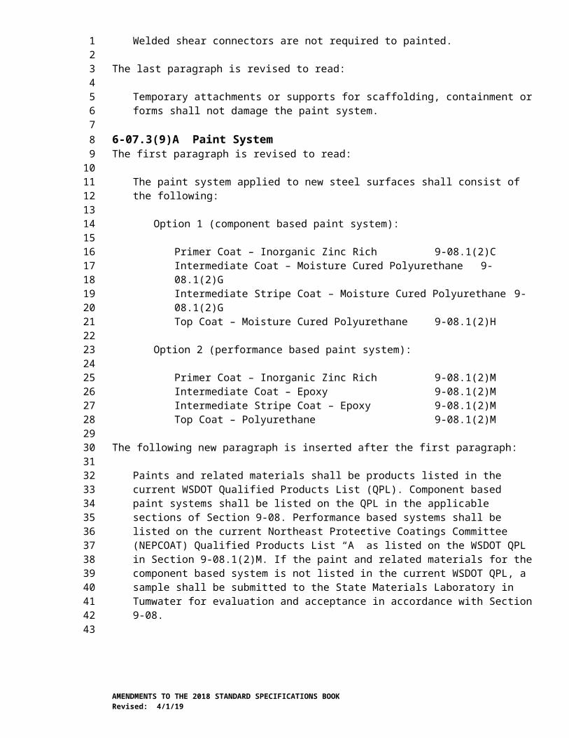
6-13.AP6Section 6-13, Structural Earth WallsAugust 6, 2018
6-13.2 MaterialsIn the first paragraph, the reference to “Aggregates for Portland Cement Concrete” is revised to read:
Aggregates for Concrete 9-03.1
6-13.3(4) Precast Concrete Facing Panel and Concrete Block FabricationItem number 1 of the sixth paragraph is revised to read:
1. Vertical dimensions shall be ± 1⁄16 inch of the Plan dimension, and the rear height shall not exceed the front height.
Item number 3 of the sixth paragraph is revised to read:
3. All other dimensions shall be ± ¼ inch of the Plan dimension.
6-14.AP6Section 6-14, Geosynthetic Retaining WallsApril 2, 2018
6-14.2 MaterialsIn the first paragraph, the references to “Portland Cement” and “Aggregates for Portland Cement Concrete” are revised to read:
Cement 9-01Aggregates for Concrete 9-03.1
6-15.AP6Section 6-15, Soil Nail WallsJanuary 7, 2019
6-15.3(7) Shotcrete FacingThe last paragraph is supplemented with the following:
After final tightening of the nut, the threads of the soil nail shall at a minimum be flush with the end of the nut.
6-16.AP6Section 6-16, Soldier Pile and Soldier Pile Tieback WallsApril 2, 2018
6-16.2 MaterialsIn the first paragraph, the reference to “Aggregates for Portland Cement Concrete” is revised to read:
Aggregates for Concrete 9-03.1
AMENDMENTS TO THE 2018 STANDARD SPECIFICATIONS BOOKRevised: 4/1/19
123
456789
10111213141516171819202122
23242526272829303132
333435363738394041
424344454647
6-18.AP6Section 6-18, Shotcrete FacingApril 1, 2019
6-18.2 MaterialsThe reference to metakaolin is deleted.
6-18.3(3) TestingIn the last sentence of the first paragraph, “AASHTO T 24” is revised to read “ASTM C1604”.
6-18.3(3)B Production TestingIn the last sentence, “AASHTO T 24” is revised to read “ASTM C1604”.
6-18.3(4) Qualifications of Contractor’s PersonnelIn the last sentence of the second paragraph, “AASHTO T 24” is revised to read “ASTM C1604”.
6-19.AP6Section 6-19, ShaftsJanuary 7, 2019
6-19.2 MaterialsIn the first paragraph, the references to “Portland Cement” and “Aggregates for Portland Cement Concrete” are revised to read:
Cement 9-01Aggregates for Concrete 9-03.1
6-19.3(1)A Shaft Construction TolerancesThe last paragraph is supplemented with the following:
The elevation of the top of the reinforcing cage for drilled shafts shall be within +6 inches and -3 inches from the elevation shown in the Plans.
6-19.3(2)D Nondestructive QA Testing Organization and PersonnelItem number 4 in the first paragraph is revised to read:
4. Personnel preparing test reports shall be a Professional Engineer, licensed under Title 18 RCW, State of Washington, and shall seal the report in accordance with WAC 196-23-020.
6-19.3(3)C Conduct of Shaft Casing Installation and Removal and Shaft Excavation OperationsThe first paragraph is supplemented with the following:
In no case shall shaft excavation and casing placement extend below the bottom of shaft excavation as shown in the Plans.
6-19.3(6)E Thermal Wire and Thermal Access Point (TAPS)The third sentence of the third paragraph is revised to read:
AMENDMENTS TO THE 2018 STANDARD SPECIFICATIONS BOOKRevised: 4/1/19
123
456789
10111213141516171819
202122232425262728293031323334353637383940414243444546474849
The thermal wire shall extend from the bottom of the reinforcement cage to the top of the shaft, with a minimum of 5-feet of slack wire provided above the top of shaft.
The following new sentence is inserted after the third sentence of the third paragraph:
All thermal wires in a shaft shall be equal lengths.
6-19.3(9)D Nondestructive QA Testing Results SubmittalThe last sentence of the first paragraph is revised to read:
Results shall be a Type 2E Working Drawing presented in a written report.
7-02.AP7Section 7-02, CulvertsApril 2, 2018
7-02.2 MaterialsIn the first paragraph, the references to “Portland Cement” and “Aggregates for Portland Cement Concrete” are revised to read:
Cement 9-01Aggregates for Concrete 9-03.1
7-02.3(6)A4 Excavation and Bedding PreparationThe first sentence of the third paragraph is revised to read:
The bedding course shall be a 6-inch minimum thickness layer of culvert bedding material, defined as granular material either conforming to Section 9-03.12(3) or to AASHTO Grading No. 57 as specified in Section 9-03.1(4)C.
7-05.AP7Section 7-05, Manholes, Inlets, Catch Basins, and DrywellsAugust 6, 2018
7-05.3 Construction RequirementsThe fourth sentence of the third paragraph is deleted.
7-08.AP7Section 7-08, General Pipe Installation RequirementsApril 2, 2018
7-08.3(3) BackfillingThe fifth sentence of the fourth paragraph is revised to read:
All compaction shall be in accordance with the Compaction Control Test of Section 2-03.3(14)D except in the case that 100% Recycled Concrete Aggregate is used.
The following new sentences are inserted after the fifth sentence of the fourth paragraph:
AMENDMENTS TO THE 2018 STANDARD SPECIFICATIONS BOOKRevised: 4/1/19
123456789
101112131415
1617181920212223242526272829303132
333435363738
3940414243444546
When 100% Recycled Concrete Aggregate is used, the Contractor may submit a written request to use a test point evaluation for compaction acceptance. Test Point evaluation shall be performed in accordance with SOP 738.
8-01.AP8Section 8-01, Erosion Control and Water Pollution ControlApril 1, 2019
8-01.1 DescriptionThis section is revised to read:
This Work consists of furnishing, installing, maintaining, removing and disposing of best management practices (BMPs), as defined in the Washington Administrative Code (WAC) 173-201A, to manage erosion and water quality in accordance with these Specifications and as shown in the Plans or as designated by the Engineer.
The Contracting Agency may have a National Pollution Discharge Elimination System Construction Stormwater General Permit (CSWGP) as identified in the Contract Special Provisions. The Contracting Agency may or may not transfer coverage of the CSWGP to the Contractor when a CSWGP has been obtained. The Contracting Agency may not have a CSWGP for the project but may have another water quality related permit as identified in the Contract Special Provisions or the Contracting Agency may not have water quality related permits but the project is subject to applicable laws for the Work. Section 8-01 covers all of these conditions.
This section is supplemented with the following new subsection:
8-01.1(1) Definitions1. pH Affected Stormwater
a. Stormwater contacting green concrete (concrete that has set/stiffen but is still curing), recycled concrete, or engineered soils (as defined in the Construction Stormwater General Permit (CSWGP)) as a natural process
b. pH monitoring shall be performed in accordance with the CSWGP, or Water Quality Standards (WQS in accordance with WAC 173-201A (surface) or 173-200C (ground)) when the CSWGP does not apply
c. May be neutralized and discharged to surface waters or infiltrated
2. pH Affected Non-Stormwater
a. Conditionally authorized in accordance with CSWGP Special Condition S.1.C., uncontaminated water contacting green concrete, recycled concrete, or engineered soils (as defined in the CSWGP)
b. Shall not be categorized as cementitious wastewater/concrete wastewater, as defined below
c. Shall be managed and treated in accordance with the CSWGP, or WQS when the CSWGP does not apply
AMENDMENTS TO THE 2018 STANDARD SPECIFICATIONS BOOKRevised: 4/1/19
1234567
89
101112131415161718192021222324252627282930313233343536373839404142434445464748495051
d. pH adjustment and dechlorination may be necessary, as specified in the CSWGP or in accordance with WQS when the CSWGP does not apply
e. May be neutralized, treated, and discharged to surface waters in accordance with the CSWGP, with the exception of water-only shaft drilling slurry. Water-only shaft drilling slurry may be treated, neutralized, and infiltrated but not discharged to surface waters (Refer to Special Conditions S1.C. Authorized Discharges and S1.d Prohibited Discharges of the CSWGP)
3. Cementitious Wastewater/Concrete Wastewater
a. Any water that comes into contact with fine cementitious particles or slurry; any water used in the production, placement and/or clean-up of cementitious products; any water used to cut, grind, wash, or otherwise modify cementitious products
b. When any water, including stormwater, commingles with cementitious wastewater/concrete wastewater, the resulting water is considered cementitious wastewater/concrete wastewater and shall be managed to prevent discharge to waters of the State, including ground water
c. CSWGP Examples include: water used for or resulting from concrete truck/mixer/pumper/tool/chute rinsing or washing, concrete saw cutting and surfacing (sawing, coring, grinding, roughening, hydro-demolition, bridge and road surfacing)
d. Cannot be neutralized and discharged or infiltrated
8-01.2 MaterialsThe first paragraph is revised to read:
Materials shall meet the requirements of the following sections:
Corrugated Polyethylene Drain Pipe 9-05.1(6)Quarry Spalls and Permeable Ballast 9-13Erosion Control and Roadside Planting 9-14Construction Geotextile 9-33
The second paragraph is deleted.
8-01.3(1) GeneralThis section is revised to read:
Adaptive management shall be employed throughout the duration of the project for the implementation of erosion and water pollution control permit requirements for the current condition of the project site. The adaptive management includes the selection and utilization of BMPs, scheduling of activities, prohibiting unacceptable practices, implementing maintenance procedures, and other managerial practices that when used singularly or in combination, prevent or reduce the release of pollutants to waters of the State. The adaptive management shall use the means and methods identified in this section and means and methods identified in the Washington State Department of Transportation’s Temporary Erosion and Sediment Control Manual or the Washington
AMENDMENTS TO THE 2018 STANDARD SPECIFICATIONS BOOKRevised: 4/1/19
123456789
10111213141516171819202122232425262728293031323334353637383940414243444546474849505152

State Department of Ecology’s Stormwater Management Manuals for construction stormwater.
The Contractor shall install a high visibility fence along the lines shown in the Plans or as instructed by the Engineer.
Throughout the life of the project, the Contractor shall preserve and protect the delineated preservation area, acting immediately to repair or restore any high visibility fencing damaged or removed.
All discharges to surface waters shall comply with surface water quality standards as defined in Washington Administrative Code (WAC) Chapter 173-201A. All discharges to groundwater shall comply with groundwater quality standards WAC Chapter 173-200. The Contractor shall comply with the CSWGP when the project is covered by the CSWGP.
Work, at a minimum, shall include the implementation of:
1. Sediment control measures prior to ground disturbing activities to ensure all discharges from construction areas receive treatment prior to discharging from the site.
2. Flow control measures to prevent erosive flows from developing.
3. Water management strategies and pollution prevention measures to prevent contamination of waters that will be discharged to surface waters or the ground.
4. Erosion control measures to stabilize erodible earth not being worked.
5. Maintenance of BMPs to ensure continued compliant performance.
6. Immediate corrective action if evidence suggests construction activity is not in compliance. Evidence includes sampling data, olfactory or visual evidence such as the presence of suspended sediment, turbidity, discoloration, or oil sheen in discharges.
To the degree possible, the Contractor shall coordinate this Work with permanent drainage and roadside restoration Work the Contract requires.
Clearing, grubbing, excavation, borrow, or fill within the Right of Way shall never expose more erodible earth than as listed below:
Western Washington(West of the Cascade
Mountain Crest)
Eastern Washington(East of the Cascade
Mountain Crest)May 1 through September 30 17 Acres April 1 through
October 31 17 Acres
October 1 through April
305 Acres
November 1 through March
315 Acres
AMENDMENTS TO THE 2018 STANDARD SPECIFICATIONS BOOKRevised: 4/1/19
123456789
10111213141516171819202122232425262728293031323334353637383940414243
44

The Engineer may increase or decrease the limits based on project conditions.
Erodible earth is defined as any surface where soils, grindings, or other materials may be capable of being displaced and transported by rain, wind, or surface water runoff.
Erodible earth not being worked, whether at final grade or not, shall be covered within the specified time period (see the table below), using BMPs for erosion control.
Western Washington(West of the Cascade
Mountain Crest)
Eastern Washington(East of the Cascade
Mountain Crest)October 1
through April 30
2 days maximum
October 1 through June
30
5 days maximum
May 1 to September 30
7 days maximum
November 1 through March
31
10 days maximum
When applicable, the Contractor shall be responsible for all Work required for compliance with the CSWGP including annual permit fees.
If the Engineer, under Section 1-08.6, orders the Work suspended, the Contractor shall continue to comply with this division during the suspension.
8-01.3(1)A SubmittalsThis section’s content is deleted.
This section is supplemented with the following new subsection:
8-01.3(1)A1 Temporary Erosion and Sediment Control PlanTemporary Erosion and Sediment Control (TESC) Plans consist of a narrative section and plan sheets that meets the Washington State Department of Ecology’s Stormwater Pollution Prevention Plan (SWPPP) requirement in the CSWGP. For projects that do not require a CSWGP but have the potential to discharge to surface waters of the state, an abbreviated TESC plan shall be used, which may consist of a narrative and/or plan sheets and shall demonstrate compliance with applicable codes, ordinances and regulations, including the water quality standards for surface waters; Chapter 173-201A of the Washington Administrative Code (WAC) and water quality standards for groundwaters in accordance with Chapter 173-200 WAC.
The Contractor shall either adopt the TESC Plan in the Contract or develop a new TESC Plan. If the Contractor adopts the TESC Plan in scenarios in which the CSWGP is transferred to the Contractor, the Contractor shall modify the TESC Plan to match the Contractor’s schedule, method of construction, and to include all areas that will be used to directly support construction activity such as equipment staging yards, material storage areas, or borrow areas. TESC Plans shall include all high visibility fence shown in the Plans. All TESC Plans shall meet the requirements of the current edition of the WSDOT Temporary Erosion and Sediment Control Manual M 3109 and be adaptively managed throughout construction based on site inspections and required sampling to maintain compliance with the CSWGP, or WQS when no CSWGP applies. The Contractor shall develop a schedule for implementation of the TESC work and incorporate it into the Contractor’s progress schedule.
AMENDMENTS TO THE 2018 STANDARD SPECIFICATIONS BOOKRevised: 4/1/19
12345678
910111213141516171819202122232425262728293031323334353637383940414243

The Contractor shall submit their TESC Plan (either the adopted plan or new plan) as Type 2 Working Drawings. At the request of the Engineer, updated TESC Plans shall be submitted as Type 1 Working Drawings.
8-01.3(1)B Erosion and Sediment Control (ESC) LeadThis section is revised to read:
The Contractor shall identify the ESC Lead at the preconstruction discussions and in the TESC Plan. The ESC Lead shall have, for the life of the Contract, a current Certificate of Training in Construction Site Erosion and Sediment Control from a course approved by the Washington State Department of Ecology. The ESC Lead must be onsite or on call at all times throughout construction. The ESC Lead shall be listed on the Emergency Contact List required under Section 1-05.13(1).
The ESC Lead shall implement the TESC Plan. Implementation shall include, but is not limited to:
1. Installing, adaptively managing, and maintaining temporary erosion and sediment control BMPs to assure continued performance of their intended function. Damaged or inadequate BMPs shall be corrected immediately.
2. Updating the TESC Plan to reflect current field conditions.
3. Discharge sampling and submitting Discharge Monitoring Reports (DMRs) to the Washington State Department of Ecology in accordance with the CSWGP.
4. Develop and maintain the Site Log Book as defined in the CSWGP. When the Site Log Book or portion thereof is electronically developed, the electronic documentation must be accessible onsite. As a part of the Site Log Book, the Contractor shall develop and maintain a tracking table to show that identified TESC compliance issues are fully resolved within 10 calendar days. The table shall include the date an issue was identified, a description of how it was resolved, and the date the issue was fully resolved.
The ESC Lead shall also inspect all areas disturbed by construction activities, all on-site erosion and sediment control BMPs, and all stormwater discharge points at least once every calendar week and within 24-hours of runoff events in which stormwater discharges from the site. Inspections of temporarily stabilized, inactive sites may be reduced to once every calendar month. The Washington State Department of Ecology’s Erosion and Sediment Control Site Inspection Form, located at https://ecology.wa.gov/Regulations-Permits/Permits-certifications/Stormwater-general-permits/Construction-stormwater-permit, shall be completed for each inspection and a copy shall be submitted to the Engineer no later than the end of the next working day following the inspection.
8-01.3(1)C Water ManagementThis section is supplemented with the following new subsections:
AMENDMENTS TO THE 2018 STANDARD SPECIFICATIONS BOOKRevised: 4/1/19
123456789
10111213141516171819202122232425262728293031323334353637383940414243444546474849
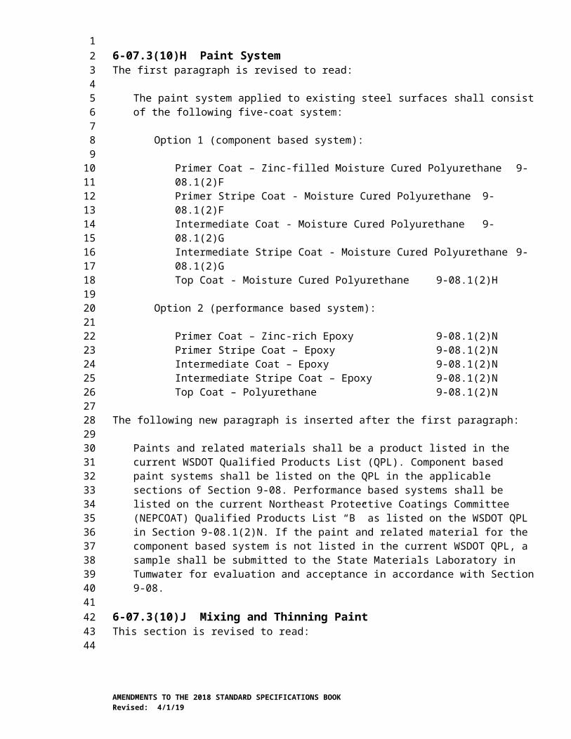
8-01.3(1)C5 Water Management for In-Water Work Below Ordinary High Water Mark (OHWM)Work over surface waters of the state (defined in WAC 173-201A-010) or below the OHWM (defined in RCW 90.58.030) shall comply with water quality standards for surface waters of the State of Washington.
8-01.3(1)C6 Environmentally Acceptable Hydraulic FluidAll equipment containing hydraulic fluid that extends from a bridge deck over surface waters of the state or below the OHWM, shall be equipped with a biodegradable hydraulic fluid. The fluid shall achieve either a Pw1 Environmental Persistence Classification stated in ASTM D6046 (≥60% biodegradation in 28 days) or equivalent standard. Alternatively, hydraulic fluid that meets International Organization for Standardization (ISO 15380), the European Union Ecolabel, or equivalent certification will also be accepted.
The Contractor shall submit a Type 1 Working Drawing consisting of a manufacturer catalog cut of the hydraulic fluid used.
The designation of biodegradable hydraulic fluid does not mean fluid spills are acceptable. The Contractor shall respond to spills to land or water in accordance with the Contract, the associated SPCC Plan, and all applicable local, state, and federal regulations.
8-01.3(1)C7 Turbidity CurtainAll Work for the turbidity curtain shall be in accordance with the manufacturer’s recommendations for the site conditions. Removal procedures shall be developed and used to minimize silt release and disturbance of silt. The Contractor shall submit a Type 2 Working Drawing, detailing product information, installation and removal procedures, equipment and workforce needs, maintenance plans, and emergency repair/replacement plans.
Turbidity curtain materials, installation, and maintenance shall be sufficient to comply with water quality standards.
The Contractor shall notify the Engineer 10 days in advance of removing the turbidity curtain. All components of the turbidity curtain shall be removed from the project.
8-01.3(1)C1 Disposal of Dewatering WaterThis section is revised to read:
When uncontaminated groundwater is encountered in an excavation on a project it may be infiltrated within vegetated areas of the right of way not designated as Sensitive Areas or incorporated into an existing stormwater conveyance system at a rate that will not cause erosion or flooding in any receiving surface water.
Alternatively, the Contractor may pursue independent disposal and treatment alternatives that do not use the stormwater conveyance system provided it is in compliance with the applicable WACs and permits.
8-01.3(1)C2 Process WastewaterThis section is revised to read:
AMENDMENTS TO THE 2018 STANDARD SPECIFICATIONS BOOKRevised: 4/1/19
123456789
10111213141516171819202122232425262728293031323334353637383940414243444546474849505152
Wastewater generated on-site as a byproduct of a construction process shall not be discharged to surface waters of the State. Some sources of process wastewater may be infiltrated in accordance with the CSWGP. Some sources of process wastewater may be disposed via independent disposal and treatment alternatives in compliance with the applicable WACs and permits.
8-01.3(1)C3 Shaft Drilling Slurry WastewaterThis section is revised to read:
Wastewater generated on-site during shaft drilling activity shall be managed and disposed of in accordance with the requirements below. No shaft drilling slurry wastewater shall be discharged to surface waters of the State. Neither the sediment nor liquid portions of the shaft drilling slurry wastewater shall be contaminated, as detectable by visible or olfactory indication (e.g., chemical sheen or smell).
1. Water-only shaft drilling slurry or water slurry with accepted flocculants may be infiltrated on-site. Flocculants used shall meet the requirements of Section 9-14.5(1) or shall be chitosan products listed as General Use Level Designation (GULD) on the Washington State Department of Ecology’s stormwater treatment technologies webpage for construction treatment. Infiltration is permitted if the following requirements are met:
a. Wastewater shall have a pH of 6.5 – 8.5 prior to discharge.
b. The amount of flocculant added to the slurry shall be kept to the minimum needed to adequately settle out solids. The flocculant shall be thoroughly mixed into the slurry.
c. The slurry removed from the shaft shall be contained in a leak proof cell or tank for a minimum of 3 hours.
d. The infiltration rate shall be reduced if needed to prevent wastewater from leaving the infiltration location. The infiltration site shall be monitored regularly during infiltration activity. All wastewater discharged to the ground shall fully infiltrate and discharges shall stop before the end of each work day.
e. Drilling spoils and settled sediments remaining in the containment cell or tank shall be disposed of in accordance with Section 6-19.3(4)F.
f. Infiltration locations shall be in upland areas at least 150 feet away from surface waters, wells, on-site sewage systems, aquifer sensitive recharge areas, sole source aquifers, well head protection areas, and shall be marked on the plan sheets before the infiltration activity begins.
g. Prior to infiltration, the Contractor shall submit a Shaft Drilling Slurry Wastewater Management and Infiltration Plan as a Type 2 Working Drawing. This Plan shall be kept on-site, adapted if needed to meet the construction requirements, and updated to reflect what is being done in the field. The Working Drawing shall include, at a minimum, the following information:
AMENDMENTS TO THE 2018 STANDARD SPECIFICATIONS BOOKRevised: 4/1/19
123456789
10111213141516171819202122232425262728293031323334353637383940414243444546474849505152

i. Plan sheet showing the proposed infiltration location and all surface waters, wells, on-site sewage systems, aquifer-sensitive recharge areas, sole source aquifers, and well-head protection areas within 150 feet.
ii. The proposed elevation of soil surface receiving the wastewater for infiltration and the anticipated phreatic surface (i.e., saturated soil).
iii. The source of the water used to produce the slurry.
iv. The estimated total volume of wastewater to be infiltrated.
v. The accepted flocculant to be used (if any).
vi. The controls or methods used to prevent surface wastewater runoff from leaving the infiltration location.
vii. The strategy for removing slurry wastewater from the shaft and containing the slurry wastewater once it has been removed from the shaft.
viii. The strategy for monitoring infiltration activity and adapting methods to ensure compliance.
ix. A contingency plan that can be implemented immediately if it becomes evident that the controls in place or methods being used are not adequate.
x. The strategy for cleaning up the infiltration location after the infiltration activity is done. Cleanup shall include stabilizing any loose sediment on the surface within the infiltration area generated as a byproduct of suspended solids in the infiltrated wastewater or soil disturbance associated with BMP placement and removal.
2. Shaft drilling mineral slurry, synthetic slurry, or slurry with polymer additives not allowed for infiltration shall be contained and disposed of by the Contractor at an accepted disposal facility in accordance with Section 2-03.3(7)C. Spoils that have come into contact with mineral slurry shall be disposed of in accordance with Section 6-19.3(4)F.
8-01.3(1)C4 Management of Off-Site WaterThis section is revised to read:
Prior to clearing and grubbing, the Contractor shall intercept all sources of off-site surface water and overland flow that will run-on to the project. Off-site surface water run-on shall be diverted through or around the project in a way that does not introduce construction related pollution. It shall be diverted to its preconstruction discharge location in a manner that does not increase preconstruction flow rate and velocity and protects contiguous properties and waterways from erosion. The Contractor shall submit a Type 2 Working Drawing consisting of the method for performing this Work.
AMENDMENTS TO THE 2018 STANDARD SPECIFICATIONS BOOKRevised: 4/1/19
123456789
101112131415161718192021222324252627282930313233343536373839404142434445464748495051

8-01.3(1)E Detention/Retention Pond ConstructionThis section is revised to read:
Permanent or temporary ponds shall be constructed before beginning other grading and excavation Work in the area that drains into that pond. Detention/retention ponds may be constructed concurrently with grading and excavation when allowed by the Engineer. Temporary conveyances shall be installed concurrently with grading in accordance with the TESC Plan so that newly graded areas drain to the pond as they are exposed.
8-01.3(2) Seeding, Fertilizing, and MulchingThis section’s title is revised to read:
8-01.3(2) Temporary Seeding and Mulching
8-01.3(2)A Preparation for ApplicationThis section is revised to read:
A cleated roller, crawler tractor, or similar equipment, which forms longitudinal depressions at least 2 inches deep shall be used for compaction and preparation of the surface to be seeded. The entire area shall be uniformly covered with longitudinal depressions formed perpendicular to the natural flow of water on the slope. The soil shall be conditioned with sufficient water so the longitudinal depressions remain in the soil surface until completion of the seeding.
8-01.3(2)A1 SeedingThis section is deleted in its entirety.
8-01.3(2)A2 Temporary SeedingThis section is deleted in its entirety.
8-01.3(2)B Seeding and FertilizingThis section, including title, is revised to read:
8-01.3(2)B Temporary SeedingTemporary grass seed shall be a commercially prepared mix, made up of low growing grass species that will grow without irrigation at the project location, and accepted by the Engineer. The application rate shall be two pounds per 1000 square feet.
The Contractor shall notify the Engineer not less than 24 hours in advance of any seeding operation and shall not begin the Work until areas prepared or designated for seeding have been accepted. Following the Engineer’s acceptance, seeding of the accepted slopes shall begin immediately.
Temporary seeding may be sown at any time allowed by the Engineer. Temporary seeding shall be sown by one of the following methods:
1. A hydro seeder that utilizes water as the carrying agent, and maintains continuous agitation through paddle blades. It shall have an operating capacity sufficient to agitate, suspend, and mix into a homogeneous slurry the specified amount of seed and water or other material. Distribution and discharge lines shall be large enough to prevent stoppage and shall be equipped with a set of
AMENDMENTS TO THE 2018 STANDARD SPECIFICATIONS BOOKRevised: 4/1/19
123456789
101112131415161718192021222324252627282930313233343536373839404142434445464748495051
hydraulic discharge spray nozzles that will provide a uniform distribution of the slurry.
2. Blower equipment with an adjustable disseminating device capable of maintaining a constant, measured rate of material discharge that will ensure an even distribution of seed at the rates specified.
3. Power-drawn drills or seeders.
4. Areas in which the above methods are impractical may be seeded by hand methods.
When seeding by hand, the seed shall be incorporated into the top ¼ inch of soil by hand raking or other method that is allowed by the Engineer.
Seed applied using a hydroseeder shall have a tracer added to visibly aid uniform application. This tracer shall not be harmful to plant, aquatic, or animal life. If Short-Term Mulch is used as a tracer, the application rate shall not exceed 250 pounds per acre.
Seed and fertilizer may be applied in one application provided that the fertilizer is placed in the hydroseeder tank no more than 1 hour prior to application.
8-01.3(2)D MulchingThis section, including title, is revised to read:
8-01.3(2)D Temporary MulchingTemporary mulch shall be straw, wood strand, or HECP mulch and shall be used for the purpose of erosion control by protecting bare soil surface from particle displacement. Mulch shall not be applied below the anticipated water level of ditch slopes, pond bottoms, and stream banks. HECP mulch shall not be used within the Ordinary High Water Mark. Non-HECP mulches applied below the anticipated water level shall be removed or anchored down so that it cannot move or float, at no additional expense to the Contracting Agency.
Straw or wood strand mulch shall be applied at a rate to achieve at least 95 percent visual blockage of the soil surface.
Short Term Mulch shall be hydraulically applied at the rate of 2500 pounds per acre and may be applied in one lift.
Moderate Term Mulch and Long Term Mulch shall be hydraulically applied at the rate of 3500 pounds per acre with no more than 2000 pounds applied in any single lift.
Mulch sprayed on signs or sign Structures shall be removed the same day.
Areas not accessible by mulching equipment shall be mulched by accepted hand methods.
8-01.3(2)F Dates for Application of Final Seed, Fertilizer, and MulchThis section is deleted in its entirety.
AMENDMENTS TO THE 2018 STANDARD SPECIFICATIONS BOOKRevised: 4/1/19
123456789
10111213141516171819202122232425262728293031323334353637383940414243444546474849505152
8-01.3(2)G Protection and Care of Seeded AreasThis section is deleted in its entirety.
8-01.3(2)H InspectionThis section is deleted in its entirety.
8-01.3(2)I MowingThis section is deleted in its entirety.
8-01.3(3) Placing Biodegradable Erosion Control BlanketThis section’s title is revised to read:
8-01.3(3) Placing Erosion Control Blanket
The first sentence of the first paragraph is revised to read:
Erosion Control Blankets are used as an erosion prevention device and to enhance the establishment of vegetation.
The second paragraph is revised to read:
When used to enhance the establishment of seeded areas, seeding and fertilizing shall be done prior to blanket installation.
8-01.3(4) Placing Compost BlanketThis section is revised to read:
Compost blankets are used for erosion control. Compost blanket shall be only be placed on ground surfaces that are steeper than 3-foot horizontal and 1-foot vertical though steeper slopes shall be broken by wattles or compost socks placed according to the Standard Plans. Compost shall be placed to a depth of 3 inches over bare soil. An organic tackifier shall be placed over the entire composted area when dry or windy conditions are present or expected. The tackifier shall be applied immediately after the application of compost to prevent compost from leaving the composted area.
Medium compost shall be used for the compost blanket. Compost may serve the purpose of soil amendment as specified in Section 8-02.3(6).
8-01.3(5) Plastic CoveringThe first paragraph is revised to read:
Erosion Control – Plastic coverings used to temporarily cover stockpiled materials, slopes or bare soils shall be installed and maintained in a way that prevents water from intruding under the plastic and prevents the plastic cover from being damaged by wind. Plastic coverings shall be placed with at least a 12-inch overlap of all seams and be a minimum of 6 mils thick. Use soil stabilization and energy dissipation BMPs to minimize the erosive energy flows coming off sloped areas of plastic (e.g., toe of slope). When feasible, prevent the clean runoff from plastic from hitting bare soil. Direct flows from plastic to stabilized outlet areas.
8-01.3(7) Stabilized Construction EntranceThe first paragraph is revised to read:
AMENDMENTS TO THE 2018 STANDARD SPECIFICATIONS BOOKRevised: 4/1/19
123456789
10111213141516171819202122232425262728293031323334353637383940414243444546474849505152
Temporary stabilized construction entrance shall be constructed in accordance with the Standard Plans, prior to construction vehicles entering the roadway from locations that generate sediment track out on the roadway. Material used for stabilized construction entrance shall be free of extraneous materials that may cause or contribute to track out.
8-01.3(8) Street CleaningThis section is revised to read:
Self-propelled pickup street sweepers shall be used to remove and collect dirt and other debris from the Roadway. The street sweeper shall effectively collect these materials and prevent them from being washed or blown off the Roadway or into waters of the State. Street sweepers shall not generate fugitive dust and shall be designed and operated in compliance with applicable air quality standards. Material collected by the street sweeper shall be disposed of in accordance with Section 2-03.3(7)C.
When allowed by the Engineer, power broom sweepers may be used in non-sensitive areas. The broom sweeper shall sweep dirt and other debris from the roadway into the work area. The swept material shall be prevented from entering or washing into waters of the State.
Street washing with water will require the concurrence of the Engineer.
8-01.3(12) Compost SocksThe first two sentences of the first paragraph are revised to read:
Compost socks are used to disperse flow and sediment. Compost socks shall be installed as soon as construction will allow but before flow conditions create erosive flows or discharges from the site. Compost socks shall be installed prior to any mulching or compost placement.
8-01.3(13) Temporary CurbThe last two sentences of the second paragraph are revised to read:
Temporary curbs shall be a minimum of 4 inches in height. Temporary curb shall be installed so that ponding does not occur in the adjacent roadway.
8-01.3(14) Temporary Pipe Slope DrainThe third and fourth paragraphs are revised to read:
The pipe fittings shall be water tight and the pipe secured to the slope with metal posts, wood stakes, or sand bags.
The water shall be discharged to a stabilized conveyance, sediment trap, stormwater pond, rock splash pad, or vegetated strip, in a manner to prevent erosion and maintain water quality compliance.
The last paragraph is deleted.
8-01.3(15) MaintenanceThis section is revised to read:
AMENDMENTS TO THE 2018 STANDARD SPECIFICATIONS BOOKRevised: 4/1/19
123456789
10111213141516171819202122232425262728293031323334353637383940414243444546474849505152
Erosion and sediment control BMPs shall be maintained or adaptively managed as required by the CSWGP until the Engineer determines they are no longer needed. When deficiencies in functional performance are identified, the deficiencies shall be rectified immediately.
The BMPs shall be inspected on the schedule outlined in Section 8-01.3(1)B for damage and sediment deposits. Damage to or undercutting of BMPs shall be repaired immediately.
In areas where the Contractor’s activities have compromised the erosion control functions of the existing grasses, the Contractor shall overseed at no additional cost to the Contracting Agency.
The quarry spalls of construction entrances shall be refreshed, replaced, or screened to maintain voids between the spalls for collecting mud and dirt.
Unless otherwise specified, when the depth of accumulated sediment and debris reaches approximately ⅓ the height of the BMP the deposits shall be removed. Debris or contaminated sediment shall be disposed of in accordance with Section 2-03.3(7)C. Clean sediments may be stabilized on-site using BMPs as allowed by the Engineer.
8-01.3(16) RemovalThis section is revised to read:
The Contractor shall remove all temporary BMPs, all associated hardware and associated accumulated sediment deposition from the project limits prior to Physical Completion unless otherwise allowed by the Engineer. When the temporary BMP materials are made of natural plant fibers unaltered by synthetic materials the Engineer may allow leaving the BMP in place.
The Contractor shall remove BMPs and associated hardware in a way that minimizes soil disturbance. The Contractor shall permanently stabilize all bare and disturbed soil after removal of BMPs. If the installation and use of the erosion control BMPs have compacted or otherwise rendered the soil inhospitable to plant growth, such as construction entrances, the Contractor shall take measures to rehabilitate the soil to facilitate plant growth. This may include, but is not limited to, ripping the soil, incorporating soil amendments, or seeding with the specified seed.
At the request of the Contractor and at the sole discretion of the Engineer the CSWGP may be transferred back to the Contracting Agency. Approval of the Transfer of Coverage request will require the following:
1. All other Work required for Contract Completion has been completed.
2. All Work required for compliance with the CSWGP has been completed to the maximum extent possible. This includes removal of BMPs that are no longer needed and the site has undergone all Stabilization identified for meeting the requirements of Final Stabilization in the CSWGP.
3. An Equitable Adjustment change order for the cost of Work that has not been completed by the Contractor.
AMENDMENTS TO THE 2018 STANDARD SPECIFICATIONS BOOKRevised: 4/1/19
123456789
10111213141516171819202122232425262728293031323334353637383940414243444546474849505152

4. Submittal of the Washington State Department of Ecology Transfer of Coverage form (Ecology form ECY 020-87a) to the Engineer.
If the Engineer approves the transfer of coverage back to the Contracting Agency, the requirement in Section 1-07.5(3) for the Contractor’s submittal of the Notice of Termination form to the Washington State Department of Ecology will not apply.
8-01.4 MeasurementThis section’s content is deleted and replaced with the following new subsections:
8-01.4(1) Lump Sum Bid for Project (No Unit Items)When the Bid Proposal contains the item “Erosion Control and Water Pollution Prevention” there will be no measurement of unit or force account items for Work defined in Section 8-01 except as described in Sections 8-01.4(3) and 8-01.4(4). Also, except as described in Section 8-01.4(3), all of Sections 8-01.4(2) and 8-01.5(2) are deleted.
8-01.4(2) Item BidsWhen the Proposal does not contain the items “Erosion Control and Water Pollution Prevention”, Section 8-01.4(1) and 8-01.5(1) are deleted and the Bid Proposal will contain some or all of the following items measured as noted.
ESC lead will be measured per day for each day that an inspection is made and a report is filed.
Erosion control blanket and plastic covering will be measured by the square yard along the ground slope line of surface area covered and accepted.
Turbidity curtains will be measured by the linear foot along the ground line of the installed curtain.
Check dams will be measured per linear foot one time only along the ground line of the completed check dam. No additional measurement will be made for check dams that are required to be rehabilitated or replaced due to wear.
Stabilized construction entrances will be measured by the square yard by ground slope measurement for each entrance constructed.
Tire wash facilities will be measured per each for each tire wash installed.
Street cleaning will be measured by the hour for the actual time spent cleaning pavement, refilling with water, dumping and transport to and from cleaning locations within the project limits, as authorized by the Engineer. Time to mobilize the equipment to or from the project limits on which street cleaning is required will not be measured.
Inlet protections will be measured per each for each initial installation at a drainage structure.
Silt fence, gravel filter, compost berms, and wood chip berms will be measured by the linear foot along the ground line of the completed barrier.
AMENDMENTS TO THE 2018 STANDARD SPECIFICATIONS BOOKRevised: 4/1/19
123456789
10111213141516171819202122232425262728293031323334353637383940414243444546474849505152

Wattles and compost socks will be measured by the linear foot.
Temporary curbs will be measured by the linear foot along the ground line of the completed installation.
Temporary pipe slope drains will be measured by the linear foot along the flow line of the pipe.
Coir logs will be measured by the linear foot along the ground line of the completed installation.
Outlet protections will be measured per each initial installation at an outlet location.
Temporary seeding, temporary mulching, and tackifiers will be measured by the acre by ground slope measurement.
Compost blanket will be measured by the square yard by ground slope surface area covered and accepted.
8-01.4(3) Reinstating Unit Items with Lump Sum Erosion Control and Water Pollution PreventionThe Contract Provisions may establish the project as lump sum, in accordance with Section 8-01.4(1) and also include one or more of the items included above in Section 8-01.4(2). When that occurs, the corresponding measurement provision in Section 8-01.4(2) is not deleted and the Work under that item will be measured as specified.
8-01.4(4) Items not included with Lump Sum Erosion Control and Water Pollution PreventionCompost blanket will be measured by the square yard by ground slope surface area covered and accepted.
Temporary mulch will be measured by the acre by ground slope surface area covered and accepted.
High visibility fence will be measured by the linear foot along the ground line of the completed fence.
8-01.5 PaymentThis section’s content is deleted and replaced with the following new subsections:
8-01.5(1) Lump Sum Bid for Project (No Unit Items)Payment will be made for the following Bid item when it is included in the Proposal:
“Erosion Control and Water Pollution Prevention”, lump sum.
The lump sum Contract price for “Erosion Control and Water Pollution Prevention” shall be full pay to perform the Work as described in Section 8-01 except for costs compensated by Bid Proposal items inserted through Contract Provisions as described in Section 8-01.4(2). Progress payments for the lump sum item “Erosion Control and Water Pollution Prevention” will be made as follows:
AMENDMENTS TO THE 2018 STANDARD SPECIFICATIONS BOOKRevised: 4/1/19
123456789
10111213141516171819202122232425262728293031323334353637383940414243444546474849505152
1. The Contracting Agency will pay 15 percent of the bid amount for the initial set up for the item. Initial set up includes the following:
a. Acceptance of the TESC Plan provided by the Contracting Agency or submittal of a new TESC Plan,
b. Submittal of a schedule for the installation of the BMPs, and
c. Identifying water quality sampling locations.
2. 70 percent of the bid amount will be paid in accordance with Section 1-09.9.
3. Once the project is physically complete and copies of the all reports submitted to the Washington State Department of Ecology have been submitted to the Engineer, and, if applicable, transference of the CSWGP back to the Contracting Agency is complete, the remaining 15 percent of the bid amount shall be paid in accordance with Section 1-09.9.
8-01.5(2) Item Bids“ESC Lead”, per day.
“Turbidity Curtain”, per linear foot.
“Erosion Control Blanket”, per square yard.
“Plastic Covering”, per square yard.
“Check Dam”, per linear foot.
“Inlet Protection”, per each.
“Gravel Filter Berm”, per linear foot.
“Stabilized Construction Entrance”, per square yard.
“Street Cleaning”, per hour.
“Silt Fence”, per linear foot.
“Wood Chip Berm”, per linear foot.
“Compost Berm”, per linear foot.
“Wattle”, per linear foot.
“Compost Sock”, per linear foot.
“Coir Log”, per linear foot.
“Temporary Curb”, per linear foot.
AMENDMENTS TO THE 2018 STANDARD SPECIFICATIONS BOOKRevised: 4/1/19
123456789
10111213141516171819202122232425262728293031323334353637383940414243444546474849505152
“Temporary Pipe Slope Drain”, per linear foot.
“Temporary Seeding”, per acre.
“Temporary Mulching”, per acre.
“Compost Blanket”, per square yard.
“Outlet Protection”, per each.
“Tackifier”, per acre.
“Erosion/Water Pollution Control”, by force account as provided in Section 1-09.6.
Maintenance and removal of erosion and water pollution control devices including removal and disposal of sediment, stabilization and rehabilitation of soil disturbed by these activities, and any additional Work deemed necessary by the Engineer to control erosion and water pollution will be paid by force account in accordance with Section 1-09.6.
To provide a common Proposal for all Bidders, the Contracting Agency has entered an amount in the Proposal to become a part of the Contractor’s total Bid.
8-01.5(3) Reinstating Unit Items with Lump Sum Erosion Control and Water Pollution PreventionThe Contract may establish the project as lump sum, in accordance with Section 8-01.4(1) and also reinstate the measurement of one or more of the items described in Section 8-01.4(2), except for Erosion/Water Pollution Control, by force account. When that occurs, the corresponding payment provision in Section 8-01.5(2) is not deleted and the Work under that item will be paid as specified.
8-01.5(4) Items not included with Lump Sum Erosion Control and Water Pollution PreventionPayment will be made for the following Bid item when it is included in the Proposal:
“High Visibility Fence”, per linear foot.
8-02.AP8Section 8-02, Roadside RestorationApril 1, 2019
This section, including all subsections, is revised to read:
8-02.1 DescriptionThis Work consists of preserving, maintaining, establishing and augmenting vegetation on the roadsides and within mitigation or sundry site areas. It includes vegetation preservation, weed and pest control, furnishing and placing topsoil, compost, and soil amendments, and furnishing and planting seed, sod and plants of all forms and container types. It includes performing plant establishment activities and soil bioengineering. Work shall be performed in accordance with these Specifications and as shown in the Plans or as designated by the Engineer.
AMENDMENTS TO THE 2018 STANDARD SPECIFICATIONS BOOKRevised: 4/1/19
123456789
10111213141516171819202122232425262728293031323334353637383940
4142434445464748495051

Trees, whips, shrubs, ground covers, cuttings, live stakes, live poles, live branches, rhizomes, tubers, rootstock, and seedlings will hereinafter be referred to collectively as “plants” or “plant material”. Grass, wildflowers, and other plant materials installed in seed form will hereinafter be referred to collectively as “seed”.
8-02.2 MaterialsMaterials shall meet the requirements of the following sections:
Erosion Control and Roadside Planting 9-14Water 9-25.2
Botanical identification and nomenclature of plant materials shall be based on descriptions by Hitchcock and Cronquist in “Flora of the Pacific Northwest”. Botanical identification and nomenclature of plant material not found in "Flora" shall be based on Bailey in “Hortus Third” or superseding editions and amendments or as referenced in the Plans.
8-02.3 Construction Requirements8-02.3(1) Responsibility During ConstructionThe Contractor shall prepare, install, and ensure adequate and proper care of all roadside seeded, planted, and lawn areas on the project until all plant establishment periods required by the Contract are complete or until Physical Completion of the project, whichever is last.
Adequate and proper care shall include, but is not limited to, keeping all plant material in a healthy, growing condition by watering, pruning, and other actions deemed necessary for plant health. This Work shall include keeping the project area free from insect infestation, weeds or unwanted vegetation, litter, and other debris along with retaining the finished grades and mulch in a neat uniform condition.
Existing desirable vegetation shall be saved and protected unless removal is required by the Contract or allowed by the Engineer.
The Contractor shall have sole responsibility for the maintenance and appearance of the roadside restoration.
8-02.3(2) Work PlansThree Work Plan submittals exist under this Section:
1. Roadside Work Plan: This plan is required when Work will disturb the roadside beyond 20 feet from the pavement or where trees or native vegetation will be removed, the Contractor shall submit a Type 2 Working Drawing.
2. Weed and Pest Control Plan: This plan is required when the proposal contains the item "Weed and Pest Control," and prior to application of any chemicals or weed control activities, the Contractor shall submit a Type 2 Working Drawing.
AMENDMENTS TO THE 2018 STANDARD SPECIFICATIONS BOOKRevised: 4/1/19
123456789
1011121314151617181920212223242526272829303132333435363738394041424344454647484950
3. Plant Establishment Plan: This plan is required when the proposal contains the item "PSIPE__", and prior to completion of Initial Planting, the Contractor shall submit a Type 2 Working Drawing.
8-02.3(2)A Roadside Work PlanThe Roadside Work Plan shall define the expected impacts to the roadside and restoration resulting from Work necessary to meet all Contract requirements. The Contractor shall define how the roadside restoration Work included in the Contract will be phased and coordinated with project Work such as earthwork, staging, access, erosion and water pollution control, irrigation, etc. The Roadside Work Plan shall include the following:
1. Limiting impacts to roadsides:
a. Limits of Work including locations of staging or parking.
b. Means and methods for vegetation protection (in accordance with Section 1-07.16(2)).
c. Locations outside of clearing limits where vegetation shall be removed to provide access routes or other needs to accomplish the Work.
d. Plans for removal, preservation and stockpile of topsoil or other native materials, if outside of clearing and grubbing limits and within the project limits.
2. Roadside Restoration:
a. Plan for propagation and procurement of plants, ground preparation for planting, and installation of plants.
b. Means and methods to limit soil compaction where seeding and planting are to occur, such as steel plates, hog fuel access roads, wood mats for sensitive areas (including removal) and decompaction for unavoidable impacts.
c. Plan and timing to incorporate or remove erosion control items.
3. Lawn Installation:
a. Schedule for lawn installation work.
b. Establishment and maintenance of lawns.
8-02.3(2)B Weed and Pest Control PlanThe Weed and Pest Control Plan shall describe all weed and pest control needs for the project.
The plan shall be prepared and signed by a licensed Commercial Pest Control Operator or Consultant. The plan for control of weeds and pests on the Contract in accordance with Section 8-02.3(3) shall include the following:
AMENDMENTS TO THE 2018 STANDARD SPECIFICATIONS BOOKRevised: 4/1/19
123456789
10111213141516171819202122232425262728293031323334353637383940414243444546474849505152

1. Names of plan preparer and pesticide operators, including contact information. The Contractor shall furnish the Engineer evidence that all operators are licensed with appropriate endorsements, and that the pesticide used is registered for use by the Washington State Department of Agriculture.
2. Means and methods of weed control, including mechanical and/or chemical.
3. Schedule for weed control including re-entry times for pesticide application by pesticide type.
4. Proposed pesticide use in accordance with Section 8-02.3(3)A: name, application rate, and Safety Data Sheets of all proposed pesticides. Include a copy of the current product label for each pesticide to be used.
5. Plan to ensure worker safety until pesticide re-entry periods are met.
8-02.3(2)C Plant Establishment PlanThe Plant Establishment Plan shall describe activities necessary to ensure continued health and vigor of planted and seeded areas in accordance with the requirements of Sections 8-02.3(12) and 8-02.3(13). Should the plan become unworkable at any time during the first-year plant establishment, the Contractor shall submit a revised plan prior to proceeding with further Work. The Plant Establishment Plan shall include:
1. Proposed scheduling of joint inspection meetings, activities, materials, equipment to be utilized for the first-year plant establishment.
2. Proposed adaptive management activities to ensure successful establishment of seeded, sodded, and planted areas.
3. A contact person.
4. Management of the irrigation system, when applicable.
8-02.3(3) Weed and Pest ControlThe Contractor shall control weed and pest species within the project limits using integrated pest management principles consisting of mechanical, biological, and chemical controls that are outlined in the Weed and Pest Control Plan or as designated by the Engineer. Controlling weeds consists of killing and removing weeds by chemical, mechanical, and hand methods.
8-02.3(3)A Chemical PesticidesChemical pesticides include, but are not restricted to, any substance or mixture of substances intended for preventing, destroying, repelling or mitigating any pest, including but not limited to, insecticides, herbicides, fungicides, adjuvants, and additives, including plant regulators, defoliants and desiccants. The Contractor shall apply chemical pesticides in accordance with the label
AMENDMENTS TO THE 2018 STANDARD SPECIFICATIONS BOOKRevised: 4/1/19
123456789
10111213141516171819202122232425262728293031323334353637383940414243444546474849505152
recommendations, the Washington State Department of Ecology, local sensitive area ordinances, and Washington State Department of Agriculture laws and regulations. Only those pesticides listed in the table Herbicides Approved for Use on WSDOT Rights of Way and accepted as part of the Weed and Pest Control Plan or by written authorization from the Engineer may be used (www.wsdot.wa.gov/maintenance/roadside/herbicide_use.htm).
The applicator shall be licensed by the State of Washington as a Commercial Applicator or Commercial Operator, with additional endorsements as required by the Special Provisions or the proposed weed control plan. All chemical pesticides shall be delivered to the job site in the original containers, or if pre-mixed off-site, a certification of the components and formulation from the supplier is required. The licensed applicator or operator shall complete WSDOT Form 540-509, Commercial Pesticide Application Record, each day the pesticide is applied and furnish a copy to the Engineer by the following business day.
The Contractor shall ensure confinement of the chemicals within the designated areas. The use of spray chemical pesticides shall require the use of anti-drift and activating agents and a spray pattern indicator unless otherwise allowed by the Engineer.
The Contractor shall assume all responsibility for rendering any area unsatisfactory for planting by reason of chemical application. Damage to adjacent areas, either on or off the Highway Right of Way, shall be repaired to the satisfaction of the Engineer or the property owner at no additional cost to the Contracting Agency.
8-02.3(3)B Planting and Lawn Area Weed ControlPlanting and lawn area weed control consists of controlling weeds and pests in planted and lawn areas shown in the Plans. This Work is included in the bid items for planting and lawn installation.
All planting and lawn areas shall be prepared so that they are weed and debris free at the time of planting and until completion of the project. The planting areas shall include the entire ground surface, regardless of cover, areas around plants, and those areas shown in the Plans.
Within planting or lawn areas, all species that are not shown in the Plans are unwanted and shall be controlled unless specifically allowed by the Engineer to remain.
Grass growing within the mulch ring of a plant, including grass applied in accordance with Sections 8-01.3(2)A1, 8-02.3(9) or 8-02.3(10), shall be considered a weed and shall be controlled on the project in accordance with the weed and pest control plan.
All applications of post-emergent herbicides shall be made while green and growing tissue is present. Residual herbicides shall not be used where rhizomatous species or perennial species are indicated.
AMENDMENTS TO THE 2018 STANDARD SPECIFICATIONS BOOKRevised: 4/1/19
123456789
101112131415161718192021222324252627282930313233343536373839404142434445464748495051

Should unwanted vegetation reach the flowering and seed stage in violation of these Specifications, the Contractor shall physically remove and bag the seed heads prior to seed dispersion. All physically removed vegetation and seed heads shall be disposed of off-site at no cost to the Contracting Agency.
8-02.3(3)C Project Area Weed and Pest ControlThe Contractor shall control weeds not otherwise covered in accordance with Section 8-02.3(3)B, in all areas within the project limits, including erosion control seeding areas and vegetation preservation areas, as designated by the Engineer.
When the Bid Item “Project Area Weed and Pest Control” is included in the Contract, the Contractor shall also control all weeds specified as noxious by the Washington State Department of Agriculture, the local Weed District, or the County Noxious Weed Control Board outside of planting areas within the project limits.
8-02.3(4) TopsoilTopsoil shall not be worked or placed when the ground or topsoil is frozen, or excessively wet.
The Contractor shall protect topsoil stockpiled for project use to prevent erosion and weed growth. Weed growth on topsoil stockpile sites shall be immediately eliminated in accordance with the accepted Weed and Pest Control Plan and Section 8-02.3(3)C.
The subsoil where topsoil is to be placed shall be tilled to a depth of 1 foot or as specified in the Special Provisions or the Plans. Topsoil of the type specified shall be evenly spread over the specified areas to the depth shown in the Plans or as otherwise ordered by the Engineer. Topsoil depths greater than 6 inches shall be placed in lifts no more than 6 inches in depth. The first lift of topsoil shall be incorporated with sub-soil to a depth of 8 inches and subsequent lifts placed and lightly tamped between lifts. After the topsoil has been spread, all large clods, hard lumps, and rocks 2 inches in diameter and larger, and litter shall be raked up, removed, and disposed.
8-02.3(4)A Topsoil Type ATopsoil Type A shall be as specified in the Special Provisions. The Contractor shall submit a certification by the supplier that the contents of the Topsoil meet the requirements in the Special Provisions.
8-02.3(4)B Topsoil Type BTopsoil Type B shall be naturally occurring topsoil taken from within the project limits and shall meet the requirements of Section 9-14.1(2). Topsoil Type B shall be taken from areas shown in the Plans to the designated depth and stockpiled at locations that will not interfere with the construction of the project, and outside of sensitive areas, as allowed by the Engineer. A minimum of two weeks prior to excavation of Topsoil Type B, the Contractor shall pre-treat the vegetation on the designated Topsoil Type B areas according to the Weed and Pest Control Plan. Areas beyond the slope stakes shall be disturbed as little as possible in the above operations and under no circumstances shall Topsoil Type B be stockpiled within 10 feet of any existing tree or vegetation area
AMENDMENTS TO THE 2018 STANDARD SPECIFICATIONS BOOKRevised: 4/1/19
123456789
10111213141516171819202122232425262728293031323334353637383940414243444546474849505152

designated to be saved and protected. The Contractor shall protect topsoil stockpile from weed infestation.
The Contractor shall set aside sufficient material to satisfy the needs of the project.
Upon completion of topsoil placement, the Contractor shall dispose of remaining stockpiled Topsoil Type B not required for use on the project at no additional expense to the Contracting Agency in accordance with Section 2-03.3(7)C.
Should a shortage of Topsoil Type B occur, and the Contractor has wasted or otherwise disposed of topsoil material, the Contractor shall furnish Topsoil Type A or C at no additional expense to the Contracting Agency.
8-02.3(4)C Topsoil Type CTopsoil Type C shall be naturally occurring topsoil obtained from a source provided by the Contractor outside of the Contracting Agency-owned Right of Way. Topsoil Type C shall meet the requirements of Sections 8-02.3(4)B and 9-14.1(3). The Contractor shall not begin removal of Topsoil Type C from the proposed source until the material has been allowed for use by the Engineer.
8-02.3(5) Roadside Seeding, Lawn and Planting Area PreparationThis Work includes preparing worked areas for the installation of all types of permanent erosion control planting. Work shall be conducted so the flow lines in drainage channels are maintained. Material displaced by the Contractor’s operations that interferes with drainage shall be removed from the channel and disposed of as allowed by the Engineer.
8-02.3(5)A Seeding Area PreparationThe Contractor shall prepare roadside seeding areas as follows:
1. Remove all excess material, debris, stumps, and rocks greater than 3 inches in diameter from areas to be seeded. Dispose of removed materials offsite.
2. Prepare roadside seeding area to a weed free and bare condition.
3. Bring area to uniform grade and install topsoil, soil amendments, or compost as specified. Any slopes 3(H) to 1(V) or steeper shall not be tilled unless otherwise specified.
4. Compact to provide a reasonably firm but friable seedbed; tractor walk to uniformly cover the surface with longitudinal depressions at least 2 inches deep formed perpendicular to the natural flow of water on the slope. Condition the soil with sufficient water so the longitudinal depressions remain in the soil surface until completion of the seeding.
5. Seed and mulch within 2 days of preparation.
AMENDMENTS TO THE 2018 STANDARD SPECIFICATIONS BOOKRevised: 4/1/19
123456789
101112131415161718192021222324252627282930313233343536373839404142434445464748495051

8-02.3(5)B Lawn Area PreparationThe Contractor shall prepare lawn areas as follows:
1. Prepare lawn area to a weed free and bare condition in accordance with Section 8-02.3(3)B.
2. Remove excess material, stumps, wood or rocks over 3 inches in diameter and remove from site.
3. Bring area to uniform grade and install topsoil or soil amendments in accordance with Section 8-02.3(4) and 8-02.3(6).
4. Till to an 8-inch depth, rake to a smooth even grade without low areas that trap water, and compact with a 50-pound roller. The finished grade of the soil shall be 1 inch below the top of all curbs, junction and valve boxes, walks, driveways, and other Structures.
5. Seed or sod the area within two days of preparation.
8-02.3(5)C Planting Area PreparationThe Contractor shall prepare planting areas as follows:
1. Prepare planting area to a weed free and bare condition in accordance with Section 8-02.3(3)B.
2. Decompact soil to a depth of 18 inches where construction activities have taken place or where native soils are compacted.
3. Return soil to uniform grade even with surrounding areas, leaving no holes or mounds over 3 inches in depth or height.
4. Remove excess material, stumps, wood or rocks over 3 inches in diameter and remove from site.
5. Apply compost or other amendments as indicated in the plans and in accordance with Section 8-02.3(6).
6. Cultivate amendments to a depth of 12 inches to provide a reasonably firm but friable planting area. Do not till any slopes 3(H) to 1(V) or steeper.
7. Return soil to a uniform finished grade, 1 inch, or the specified depth of mulch plus 1 inch, below walks, curbs, junction and valve boxes, catch basins, and driveways, unless otherwise specified.
8. Begin planting and mulching the area within two days of final preparation.
8-02.3(6) Soil AmendmentsThe Contractor shall place soil amendments of the type, quality, and quantities specified where shown in the Plans or as specified in the Special Provisions. Areas receiving soil amendments shall be bare soil or vegetation free prior to application.
AMENDMENTS TO THE 2018 STANDARD SPECIFICATIONS BOOKRevised: 4/1/19
123456789
10111213141516171819202122232425262728293031323334353637383940414243444546474849505152
All soil amendments shall be installed as shown in the Plans within 30 calendar days after delivery to the project site.
8-02.3(6)A CompostCompost used for soil amendments shall be Fine Compost unless otherwise designated in the Plans. When compost blanket is used for temporary erosion control, the compost blanket may be incorporated into the soil immediately prior to planting when used as compost soil amendment. The area shall be prepared in accordance with Section 8-02.3(5) prior to placing compost.
8-02.3(6)B FertilizersThe Contractor shall apply fertilizer in the form, mixture, and rate specified in the Special Provisions or as directed by the Engineer. Application procedures shall be in accordance with the manufacturer’s recommendations unless otherwise specified in the Special Provisions.
The Contractor shall submit a guaranteed fertilizer analysis label for the selected product a minimum of one week prior to application for acceptance. Following the Engineer’s acceptance, fertilizing of the accepted ground or vegetated surfaces shall begin immediately.
In seeding and lawn areas to be fertilized, the fertilizer shall be applied concurrently with the seed. When fertilizer is hydraulically applied, the fertilizer shall be suitable for application with seeding as specified in Section 8-02.3(9)C. If hydroseeding, the fertilizer shall be placed in the hydroseeder tank no more than 1 hour prior to application.
Fertilizers for planting areas shall be applied concurrently with compost and applied prior to incorporation, unless tablet form fertilizer is specified. Where tablet form fertilizer is specified, fertilizer shall be applied concurrently with plant installation.
Fertilizer sprayed on signs or sign structures shall be removed the same day.
Areas not accessible by fertilizing equipment shall be fertilized by allowed hand methods.
Second Application: A second application of fertilizer shall be applied as specified in the Special Provisions at the locations designated in the Plans. The fertilizer shall be applied during the months of March, April, or May of the following year after the initial seeding, planting, or lawn installation. The fertilizer shall be dry granular pellets or pearls and applied in accordance with the manufacturer’s recommendations or as specified in the Special Provisions.
8-02.3(7) Layout of Planting, Lawn and Seeding AreasThe Contractor shall lay out and prepare planting and lawn areas and receive the Engineer’s acceptance of layout and preparation prior to any installation activities. The Contractor shall stake the location of all trees larger than 1-inch caliper and the perimeter of all planting areas for acceptance by the Engineer prior to any installation activities.
AMENDMENTS TO THE 2018 STANDARD SPECIFICATIONS BOOKRevised: 4/1/19
123456789
101112131415161718192021222324252627282930313233343536373839404142434445464748495051

The Contractor shall locate all trees to be planted in mowable grass areas a minimum of 10 feet from the edge of planting areas, other trees, fence lines, and bottom of ditches unless otherwise specified.
Tree locations shown in the Plans shall be considered approximate unless shown with stationing and offset distance. In irrigated areas, trees shall be located so their trunk is a minimum of ⅓ of the spray radius away from the nearest sprinkler head.
Unless otherwise shown, planting areas located adjacent to Roadways shall begin 6 feet from the edge of shoulder on roadway fills and begin 5 feet up on the back slope from the bottom on roadway cut sections. Plants within planting areas shall be located such that mature branching pattern will not block sight distance, signs, or other traffic-related devices. No trees shall be placed where the mature canopy will grow to within 10 feet of existing power lines. Where roadside ditches are present, planting areas shall begin 5 feet from the centerline of the ditch unless shown otherwise in the Plans.
8-02.3(8) Planting8-02.3(8)A Dates and Conditions for PlantingNo plant material shall be planted until it has been inspected and accepted for planting by the Engineer. Rejected material shall be removed from the project site immediately. All plants for the project or a sufficient quantity to plant 1-acre of the site, whichever is less, shall be received on site prior to the Engineer beginning inspection of the plants.
Under no circumstances will planting be permitted during unsuitable soil or weather conditions as determined by the Engineer. Unsuitable conditions may include frozen soil, freezing weather, saturated soil, standing water, high winds, heavy rains, and high water levels. The ground shall be moist at the time of planting. All planting shall be accomplished during the following periods:
1. Non-Irrigated Plant MaterialWestern Washington (West of the Cascade Mountain Crest) – October 1 to March 1.Eastern Washington (East of the Cascade Mountain Crest) – October 1 to November 15.
2. Irrigated Plant Material
In irrigated areas, plant material shall not be installed until the irrigation system is fully operational and accepted by the Engineer. Trees and shrubs may be planted in irrigated areas during the non-irrigated planting window before the irrigation system is functional with the written concurrence of the Engineer only if the irrigation system is guaranteed to be operational prior to the end of the non-irrigated planting window.
8-02.3(8)B Plant InstallationThe Contractor shall handle plant material in the following manner:
1. Root systems shall be kept covered and damp at all times. Plant material shall be kept in containers until the time of planting.
AMENDMENTS TO THE 2018 STANDARD SPECIFICATIONS BOOKRevised: 4/1/19
123456789
10111213141516171819202122232425262728293031323334353637383940414243444546474849505152

2. Roots shall not be bunched, curled, twisted, or unreasonably bent when placed in the planting hole. Bare root plant material shall be dormant at the time of harvesting and planting. The root systems of all bare root plant material shall be dipped in a slurry immediately prior to planting.
3. Plant material supplied in wrapped balls shall not be removed from the wrapping until the time of planting at the planting location. The root system of balled plant material shall be moist at the time of planting. Root balls shall be loosened prior to planting. All burlap, baskets, string, wire and other such materials shall be removed from the hole when planting balled plants.
4. Plant cutting material shall be dormant at the time of cutting and planting. All cuttings shall be installed immediately if buds begin to swell.
5. Plants shall be placed with the crown at the finished grade. In their final position, plants shall have their top true root (not adventitious root) no more than 1 inch below the soil surface, no matter where that root was located in the original root ball or container. The backfill material, including container and root ball soil, shall be thoroughly watered on the same day that planting occurs regardless of season.
When installing plants, the Contractor shall dig planting holes three times the diameter of the container or root ball size. Any glazed surface of the planting hole shall be roughened prior to planting.
8-02.3(8)C Pruning, Staking, Guying, and WrappingPlants shall be pruned at the time of planting, only to remove minor broken or damaged twigs, branches or roots. Pruning shall be performed with a sharp tool and shall be done in such a manner as to retain or to encourage natural growth characteristics of the plants. All other pruning shall be performed only after the plants have been in the ground at least 1 year and when plants are dormant.
Trees shall only be staked when so noted in the Plans. Each tree shall be staked or guyed before completion of the backfilling in accordance with the details shown in the Plans.
Trees shall be wrapped when so noted in the Plans.
8-02.3(9) Seeding, Fertilizing, and MulchingFor all seed, the Contractor shall furnish the following documentation to the Engineer:
1. The state or provincial seed dealer license and endorsements.
2. Copies of Washington State Department of Agriculture (WSDA) test results on each lot of seed. Test results shall be within six months prior to the date of application.
AMENDMENTS TO THE 2018 STANDARD SPECIFICATIONS BOOKRevised: 4/1/19
123456789
10111213141516171819202122232425262728293031323334353637383940414243444546474849505152
8-02.3(9)A Dates for Application of SeedUnless otherwise allowed by the Engineer, the Contractor shall apply seed for permanent erosion control during the following periods:
Western Washington1
(West of the Cascade Mountain Crest)
Eastern Washington(East of the Cascade Mountain
Crest)March 1 through May 15
September 1 through October 1October 1 through November 15
1Seeding may be allowed outside these dates when allowed by the Engineer.
All roadway excavation and embankment ground surfaces that are completed to final grades shall be prepared and seeded during the first available seeding window. When environmental conditions are not conducive to satisfactory results, the Engineer may suspend the seeding Work until such time that the desired results are likely to be obtained. If seeding is suspended, temporary erosion control methods according to Section 8-01 shall be used to protect the bare soil until seeding conditions improve.
8-02.3(9)B Seeding and FertilizingThe Contractor shall prepare the seeding area in accordance with Section 8-02.3(5)A and apply seed at the rate and mix specified in the Special Provisions. The Contractor shall notify the Engineer within 5 days in advance of any seeding operation and shall not begin the Work until areas prepared or designated for seeding have been accepted. Following the Engineer’s acceptance, seeding of the accepted ground surfaces shall begin immediately.
Seeding shall not be done during windy weather or when the ground is frozen, or excessively wet.
When seeding by hand, the seed shall be incorporated into the top ¼ inch of soil by hand raking or other method that is allowed by the Engineer.
Seed applied as a separate operation using a hydroseeder shall have a tracer added to visibly aid uniform application. The tracer shall be HECP Short-Term Mulch applied at a rate of 200 to 250 pounds per acre and the tracer shall carry the measured specified seeding rate.
8-02.3(9)C Seeding with Fertilizers and MulchesWhen the Proposal includes any variation of seeding, fertilizing, and without mulching, the seed and fertilizer shall be applied in one application followed by mulching. West of the Cascade Mountains, seed, fertilizer, and mulch may be completely applied in one application. East of the Cascades, seeding, fertilizing, and mulching shall not be applied as a single application unless allowed by the Engineer in writing prior to application. The fertilizing and mulching shall meet the requirements of Sections 8-02.3(6) and 8-02.3(11).
8-02.3(9)D InspectionSeeded areas will be inspected upon completion of seeding, fertilizing, and mulching. The Work in any area will not be measured for payment until a
AMENDMENTS TO THE 2018 STANDARD SPECIFICATIONS BOOKRevised: 4/1/19
12345
6789
101112131415161718192021222324252627282930313233343536373839404142434445
uniform distribution of the materials is accomplished at the specified rate. Areas that have not received a uniform application of seed, fertilizer, and mulch at the specified rate, as determined by the Engineer, shall be re-seeded, re-fertilized, or re-mulched prior to payment for seeding within a designated area.
8-02.3(9)E Protection and Care of Seeded AreasThe Contractor shall install and establish a stable and weed free stand of grass as specified within all designated permanent seeding areas. A stable stand of grass shall meet the following requirements:
1. A dense and uniform canopy cover, 70% for Western Washington and 50% for Eastern Washington, of specified species covers all seeded areas after 3 months of active growth following germination during the growing season. Canopy cover is defined as the cover of living and vigorous grass blades, leaves, and shoots of specified species. Volunteer species, weeds, woody plants, or other undesirable vegetation shall not factor into the canopy cover. Growth and establishment may require supplemental irrigation to meet cover requirements.
2. Stand health is evident by vigorously growing planted species having a uniform rich-green appearance and with no dead patches or major gaps of growth. A stand of grass that displays rusting, wilting, stunted growth, disease, yellowing or browning of leaves, or bare patches does not meet the stand health requirement.
3. The Contractor shall establish a stable stand of grass free of all weeds, non-specified grasses, and other undesirable vegetation. Weed control shall be in accordance with the Weed and Pest Control Plan and occur on a monthly basis during the establishment period and through the life of the Contract.
4. Remove all trash, rocks, construction debris, and other obstructions that may be detrimental to the continued establishment of future seeding.
In addition to the requirements of Section 1-07.13(1), restoration of eroded areas including clean up, removal, and proper disposal of eroded material, filling and raking of eroded areas with Topsoil Type A or fine compost, and re-application of the specified seed, fertilizer, and mulch shall occur at no additional cost to the Contracting Agency.
8-02.3(10) Lawn Installation8-02.3(10)A Dates and Conditions for Lawn InstallationIn irrigated areas, lawn installation shall not begin until the irrigation system is fully operational.
Unless otherwise allowed by the Engineer, seeded lawn installation shall be performed during the following time periods at the location shown:
Western Washington Eastern Washington
AMENDMENTS TO THE 2018 STANDARD SPECIFICATIONS BOOKRevised: 4/1/19
123456789
101112131415161718192021222324252627282930313233343536373839404142434445464748495051

(West of the Cascade Mountain Crest)
(East of the Cascade Mountain Crest)
March 1 through May 15September 1 through October 1
October 1 through November 15
When irrigation system is operationalMarch 1 through October 1
When irrigation system is operationalMarch 1 through November 1
8-02.3(10)B Lawn Seeding and SoddingThe Contractor shall prepare the lawn area in accordance with Section 8-02.3(5) and apply seed at the mix and rate of application as specified in the Special Provisions.
The Contractor shall have the option of sodding in lieu of seeding for lawn installation at no additional expense to the Contracting Agency. Seeding in lieu of sodding will not be allowed.
Seed placed by hand shall be raked into the soil. Following raking, the seeded soil shall be rolled with a smooth 50-pound roller. Sod strips shall be placed within 48 hours of being cut. Placement shall be without voids and have the end joints staggered. Following placement, the sod shall be rolled with a smooth roller to establish contact with the soil.
Barriers shall be erected, with warning signs where necessary, to preclude pedestrian traffic access to the newly placed lawn during the establishment period.
8-02.3(10)C Lawn EstablishmentLawn establishment shall consist of caring for all new lawn areas within the limits of the project.
The lawn establishment period shall begin immediately after the lawn seeding or sodding has been accepted by the Engineer and shall extend to the end of four mowings or 20 working days whichever is longer. The mowings shall be done in accordance with Section 8-02.3(10)D.
During the lawn establishment period, the Contractor shall ensure the continuing healthy growth of the turf. This care shall include keeping the project in a presentable condition including, but not limited to, removal of litter, mowing, trimming, removal of grass clippings, edging, fertilization, insecticide and fungicide applications, weed control, watering, repairing the irrigation system, and repair and reseeding all damaged areas.
Temporary barriers shall be removed only when directed by the Engineer.
All Work performed under lawn establishment shall comply with established turf management practices.
Acceptance of lawn planting as specified will be based on a uniform stand of grass and a uniform grade at the time of final inspection. The Contractor shall recultivate, re-grade, reseed, and refertilize areas that are bare or have a poor stand of grass or not having a uniform grade through any cause before final inspection at no additional cost to the Contracting Agency.
AMENDMENTS TO THE 2018 STANDARD SPECIFICATIONS BOOKRevised: 4/1/19
123456789
10111213141516171819202122232425262728293031323334353637383940414243444546
8-02.3(10)D Lawn MowingLawn mowing shall begin immediately after the lawn establishment period has been accepted by the Engineer and shall extend to the end of the Contract or the first-year plant establishment, whichever is last.
The Contractor shall accomplish the following minimum requirements:
1. Mow, trim, and edge as often as conditions dictate, at a minimum, once per week between April and September. Maximum height of lawn shall not exceed 3 inches. The cutting height shall be 2 inches. Cuttings, trimmings, and edgings shall be disposed of off the project site. When the Engineer allows the use of a mulching mower, trimmings may be left in place.
2. Water as often as conditions dictate depending on weather and soil conditions.
3. Provide fertilizer, weed control, water, and other measures as necessary to establish and maintain a healthy stand of grass.
8-02.3(11) MulchMulches associated with seeding and planting shall be of the type specified in the Special Provisions or as indicated in the Plans. The Contractor shall evenly apply mulch at the rates indicated in the Plans. Mulches shall not be placed below the anticipated water level of ditch slopes, pond bank slopes, and stream banks, or in areas of standing or flowing water.
8-02.3(11)A Mulch for Seeding AreasThe Contractor shall furnish and evenly apply Hydraulically Applied Erosion Control Product (HECP) Long Term Mulch at the rates indicated and in accordance with the Manufacturer’s specifications unless otherwise specified.
HECP Long Term Mulch shall be hydraulically applied at the rate of 3500 pounds per acre with no more than 2000 pounds applied in any single lift. HECP mulch shall not be used within the Ordinary High Water Mark.
Mulch sprayed on signs or sign Structures shall be removed the same day.
Areas not accessible by mulching equipment shall be mulched by accepted hand methods.
HECP Long Term Mulch may be applied with seed and fertilizer west of the summit of the Cascade Range. East of the summit of the Cascade Range, seed and fertilizer shall be applied in a single application followed by the application of mulch.
8-02.3(11)B Bark or Woodchip MulchThe Contractor shall apply bark or wood chip mulch of the type and depth specified where shown in the Plans or as specified in the Special Provisions.
AMENDMENTS TO THE 2018 STANDARD SPECIFICATIONS BOOKRevised: 4/1/19
123456789
101112131415161718192021222324252627282930313233343536373839404142434445464748495051
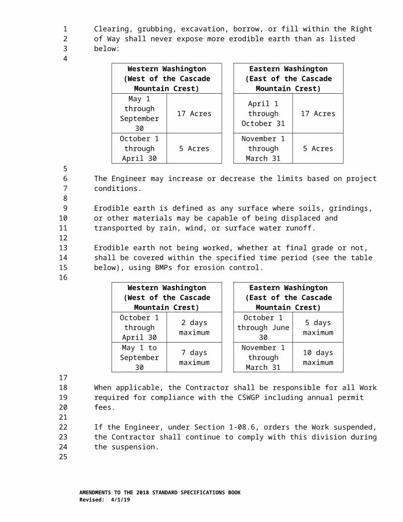
The Contractor shall complete final grading and placement/incorporation of soil amendments within the planting area prior to placement of mulch. Areas receiving bark mulch shall be bare soil or vegetation free before application, except where trees and other plants are specifically identified in the Plans or designated by the Engineer to be saved and protected.
Bark or wood chip mulch shall be placed to a uniform non-compacted depth of 3 inches over all planting areas unless otherwise specified. Mulch shall be feathered to the base of the plant and 1 inch below the top of junction and valve boxes, curbs, and pavement edges.
Any contamination of the mulch due to the Contractor’s operations shall be corrected to its former condition at no additional cost to the Contracting Agency. Mulch placed to a thickness greater than specified shall be at no additional cost to the Contracting Agency.
The Contractor shall keep plant material crowns, runners, and branches free of mulch at all times.
8-02.3(11)C Bark or Woodchip Mulch RingsThe Contractor shall apply mulch rings around plants installed within existing vegetation areas or within seeded areas as shown in the Plans. Bark or wood chip mulch rings shall be applied to the surface of vegetation free amended soil in the isolated plant locations where shown in the Plans or as specified in the Special Provisions. Bark or wood chip mulch shall be placed to a uniform non-compacted depth of 3 inches to a radius of 2 feet around all plants within interplanted plant locations.
8-02.3(12) Completion of Initial PlantingUpon completion of the initial planting within a designated area, the Engineer will make an inspection of all planting areas. The Engineer will notify the Contractor, in writing, of any replacements or corrective action necessary to meet the plant installation requirements. The Contractor shall replace all plants and associated materials rejected or missing and correct unsatisfactory conditions.
Completion of the initial planting within a designated area includes the following conditions:
1. 100 percent of each of the plant material categories are installed as shown in the Plans.
2. Planting Area is cleaned up.
3. Repairs are completed, including but not limited to, full operation of the irrigation system.
4. Mulch coverage is complete.
5. All weeds are controlled.
AMENDMENTS TO THE 2018 STANDARD SPECIFICATIONS BOOKRevised: 4/1/19
123456789
1011121314151617181920212223242526272829303132333435363738394041424344454647484950
8-02.3(13) Plant EstablishmentPlant establishment consists of caring for all plants and planting areas within the project limits. The provisions of Sections 1-07.13(2) and 1-07.13(3) do not apply to this Section.
When the Proposal includes the bid item PSIPE____ (Plant Selection Including Plant Establishment), that bid item includes one year of plant establishment Work. The first year of plant establishment shall begin immediately upon written notification from the Engineer of the completion of initial planting for the project. The first-year plant establishment period shall be a minimum of one calendar year. The one calendar year shall be extended an amount equal to any periods where the Contractor does not comply with the plant establishment requirements and plan.
During the first-year plant establishment period, the Contractor shall perform all Work necessary to ensure the resumption and continued growth of the transplanted material. This Work shall include, but is not limited to, applying water, removing foreign, dead, or rejected plant material, maintaining all planting areas in a weed-free condition, and replacing all unsatisfactory plant material planted under the Contract. If plants are stolen or damaged by the acts of others, the Contracting Agency will pay invoice cost only for the replacement plants with no mark-up and the Contractor will be responsible for the labor to install the replacement plants. Other weed control within the project limits but outside of planting, lawn, or seeding areas shall be as specified in Section 8-02.3(3)C.
During the first year of plant establishment, the Contractor shall meet monthly or at an agreed upon schedule with the Engineer for the purpose of joint inspection of the planting material. The Contractor shall correct all unsatisfactory conditions identified by the Engineer within a 10-day period immediately following the inspection. If plant replacement is required, the Contractor shall, within the 10-day period, submit a plan and schedule for the plant procurement and replacement to occur during the planting period as designated in Section 8-02.3(8). At the end of the plant establishment period, plants that do not show normal growth shall be replaced and all staking and guying that remain on the project shall be removed unless otherwise allowed by the Engineer.
All automatic irrigation systems shall be operated fully automatic during the plant establishment period and until final acceptance of the Contract. Payment for water used to water in plants, or hand watering of plant material or lawn areas unless otherwise specified, is the responsibility of the Contractor during the first-year plant establishment period.
Subsequent year plant establishment periods shall begin immediately at the completion of the preceding year’s plant establishment period. Each subsequent plant establishment period shall be one full calendar year in duration.
During the plant establishment period(s) after the first year plant establishment, the Work necessary for the continued healthy and vigorous growth of all plants material shall be performed as directed by the Engineer.
Payment for water used to water plants during the subsequent year(s) of plant establishment will be paid under the plant establishment item.
AMENDMENTS TO THE 2018 STANDARD SPECIFICATIONS BOOKRevised: 4/1/19
123456789
10111213141516171819202122232425262728293031323334353637383940414243444546474849505152
8-02.3(14) Plant ReplacementThe Contractor shall be responsible for growing or arrange to provide sufficient plants for replacement of all plant material rejected through first-year plant establishment. All replacement plant material shall be inspected and accepted by the Engineer prior to installation. All rejected plant material shall be replaced with acceptable plants meeting the specifications and installed according to the requirements of this Section at dates allowed by the Engineer.
All replacement plants shall be of the same species as the plants they replace and meet the requirements of Section 9-14.8 unless otherwise allowed by the Engineer. Plants may vary in size reflecting one season of growth should the Contractor elect to hold plant material under nursery conditions for an additional year to serve as replacement plants. Replacement plant material larger than specified in the Plans shall meet the applicable section requirements of the ASNS for container class, ball size, spread, and branching characteristics.
8-02.3(15) BioengineeringBioengineering consists of using plant materials for the purpose of streambank or earthen slope construction and surface stabilization. This Work may include installing woody plant cuttings in various forms as well as part of streambank or earthen slope construction.
8-02.3(15)A FascinesLive fascines shall be constructed of live and dead cuttings bundled together with a diameter of 8 to 18 inches. Live cuttings shall be the species shown in the Plans. Dead branches may be cuttings from any woody, non-invasive plant native to the project area. Dead branches may be placed within the live fascine and on the side exposed to the air. Live branches shall be placed in contact with the soil along their entire length. Each live fascine must contain a minimum of eight live branches. Dead branches shall constitute no more than 40 percent of the total fascine content.
The total length of each live fascine shall be a minimum of 5 feet. Branches shall be bundled into log-like forms and bound with biodegradable twine spaced at 1-foot intervals along the entire length of the live fascine. Live fascines shall be installed horizontally in a trench whose depth shall be ½ the diameter of the live fascine. Secure the live fascine with live stakes 3 feet in length and ¾ inch in diameter placed at 18-inch intervals. A minimum of three live stakes shall be used per fascine. The live stakes shall be driven through the live fascine vertically into the slope. The ends of live fascines shall be woven together so that no gap remains between the two sections of the live fascine.
Prior to being covered with soil, the fascine shall be thoroughly watered. Once the fascine is covered with 6 inches of soil, the soil covering the fascine shall be thoroughly watered.
When used to remedy erosion areas, live fascines shall extend a minimum of two feet beyond the visible area of erosion and soil disturbance. The locations for live fascines and live stake rows shall be identified in the field for review and acceptance by the Engineer. The Engineer may require adjustment of
AMENDMENTS TO THE 2018 STANDARD SPECIFICATIONS BOOKRevised: 4/1/19
123456789
10111213141516171819202122232425262728293031323334353637383940414243444546474849505152
fascine locations prior to installation in order to best accomplish the intended functions.
Plant replacement during plant establishment for “PSIPE Live Fascine” will be required for any section void of live shoots for a length of 3 feet or more. Replacement shall consist of installing live stakes, spaced 1 foot apart above the fascine within the area void of live shoots. Live stakes shall be of the same species as the live fascine and shall have a minimum length of 3 feet and a minimum diameter of ¾ inch. The requirements of Section 8-02.3(8) apply to PSIPE Live Fascine.
8-02.3(15)B Brush MattressLive brush mattress shall be constructed of live branch cuttings, live poles, jute rope and topsoil. The live cuttings and live poles shall be from the plant species designated in the Plans. Live branch cuttings shall be placed with the cut ends oriented down slope as shown in the Plans. Cuttings shall overlap from side to side and from top to bottom as each layer is constructed. The live branches in each succeeding upper layer shall overlap the adjacent lower layer by a minimum of 6 inches. A maximum of 20 percent of the branches may be dead branches, but the live branches shall be distributed evenly to provide even rooting and growth over the entire area of the brush mattress.
The Contractor shall anchor the live brush mattress to the slope using stakes and jute rope as shown in the Plans. Initially, the stakes shall be installed to protrude above the live brush mattress. The Contractor shall attach the jute rope to the stakes and tighten the rope by tamping the stakes further into the bank, pulling the live brush mattress tight against the soil surface. The Contractor shall cover the live brush mattress with sufficient stockpiled topsoil to ensure good soil contact with the live plant material.
Plant replacement during plant establishment for “PSIPE Live Brush Mattress” will be required for any section void of live shoots for an area of 25 square feet or more. Replacement shall consist of installing live stakes, spaced 3 feet apart in a triangular pattern within the area void of live shoots. Live stakes shall be of the same species as the live brush mattress and shall have a minimum length of 3 feet and a minimum diameter of ¾ inch. The requirements of Section 8-02.3(8) apply to PSIPE Brush Mattress.
8-02.3(15)C Brush LayerBrush layers shall be constructed of live branch cuttings, randomly mixed, from the plant species listed under the brush layer heading in the Plans. The number of branches required will vary depending on the average branch diameter and layer thickness.
Brush layers shall be placed in a trench dug at a 45 degree incline into the slope or stream bank. Two-thirds to three-fourths of the length of the live branches shall be buried. Soil shall be firmly tamped in place. Succeeding layers shall be spaced as detailed in the Plans. Brush layer placed in stream banks shall be angled downstream.
Brush layers may include plant establishment when designated as PSIPE Brush Layer. Plant replacement for PSIPE Brush Layer will be required for
AMENDMENTS TO THE 2018 STANDARD SPECIFICATIONS BOOKRevised: 4/1/19
123456789
10111213141516171819202122232425262728293031323334353637383940414243444546474849505152

each section void of live shoots for a continuous distance of 3 feet or more. The requirements of Section 8-02.3(8) apply to PSIPE Brush Layer.
8-02.3(16) Roadside Maintenance Under ConstructionWhen the Contract includes the item, Roadside Maintenance Under Construction, this Work includes roadside mowing and ditch maintenance, and noxious weed control outside of planting areas according to Section 8-02.3(3)C.
8-02.3(16)A Roadside MowingThe Contractor shall mow designated roadside grass areas to the limits designated by the Engineer. Roadside mowing is limited to slopes not steeper than 3(H) to 1(V).
The Contractor shall mow according to the following requirements:
1. Trim around traffic equipment, structures, planting areas, or other features extending above ground preceding or simultaneously with each mowing.
2. Maintain grass between 4 and 12 inches in height.
3. Operate mowing equipment with suitable guards to prevent throwing rocks or debris onto the traveled way or off of the Contracting Agency property. Power driven equipment shall not cause ruts, deformation, and compaction of the vegetated soil.
4. Removing clippings is required on the traveled way, shoulders, walkways, or Structures.
5. Restore soil rutting to a smooth and even grade at the direction of the Engineer.
8-02.3(16)B Ditch MaintenanceThe Contractor shall maintain drainage for the duration of the Contract according to the following requirements:
1. Maintain flow lines in drainage channels and roadside ditches.
2. Cutting or trimming vegetation within drainage channels to maintain positive flow.
3. Remove dirt and debris from inside of culverts or any drainage area where runoff has allowed accumulations and re-seed for erosion control.
4. Restore channels to previous operational condition.
8-02.4 MeasurementTopsoil, bark or woodchip mulch and soil amendments will be measured by the acre or the square yard along the grade and slope of the area covered immediately after placement. Weed control pre-treatment of topsoil areas, excavation, and stockpiling are included in the bid item “Topsoil Type ___.
AMENDMENTS TO THE 2018 STANDARD SPECIFICATIONS BOOKRevised: 4/1/19
123456789
10111213141516171819202122232425262728293031323334353637383940414243444546474849505152

Bark or woodchip mulch rings will be measured per each.
Compost will be measured by the acre or the square yard along the grade and slope of the area covered immediately after application.
Seeding, fertilizing, and mulching will be measured by the acre or the square yard by ground slope measurement or through the use of design data.
Seeding and fertilizing by hand will be measured by the square yard. No adjustment in area size will be made for the vegetation free zone around each plant.
Seeded lawn, sod installation, and lawn mowing will be measured along the ground slope and computed in square yards of actual lawn completed, established, and accepted.
Plant selection will be measured per each.
PSIPE __ (Plant Selection Including Plant Establishment) will be measured per each.
Live Pole will be measured per each.
Live Stake Row will be measured by the linear foot along the ground slope line.
The pay quantities for plant materials will be determined by count of the number of satisfactory plants in each category accepted by the Engineer.
Fascine and PSIPE live fascine will be measured by the linear foot along the ground slope line.
Brush mattress and PSIPE live brush mattress will be measured by the surface square yard along the ground slope line.
Brush layer and PSIPE brush layer will be measured by the linear foot along the ground slope line.
Water will be measured in accordance with Section 2-07.4. Measurement will be made of only that water hauled in tank trucks or similar equipment.
8-02.5 PaymentPayment will be made for each of the following listed Bid items that are included in the Proposal:
“Project Area Weed and Pest Control” will be paid in accordance with Section 1-09.6.For the purpose of providing a common Proposal for all Bidders, the Contracting Agency entered an amount for “Project Area Weed and Pest Control” in the Proposal to become a part of the total Bid by the Contractor. Payment under this item will be made only when the Work is not already covered by other items.
“Topsoil Type ____”, per acre.
AMENDMENTS TO THE 2018 STANDARD SPECIFICATIONS BOOKRevised: 4/1/19
123456789
101112131415161718192021222324252627282930313233343536373839404142434445464748495051
The unit Contract price per acre for “Topsoil Type ____” shall be full payment for all costs for the specified Work.
“Fine Compost ”, per acre or per square yard.“Medium Compost”, per acre or per square yard.“Coarse Compost”, per acre or per square yard.The unit Contract price per acre for “Fine Compost”, “Medium Compost” or “Coarse Compost” shall be full pay for furnishing and spreading the compost onto the existing soil.
“Soil Amendment”, per acre.The unit Contract price per acre for “Soil Amendment” shall be full pay for furnishing and incorporating the soil amendment into the existing soil.
“Plant Selection ___”, per each.The unit Contract price for “Plant Selection ___”, per each shall be full pay for all Work to perform the work as specified within the planting area prior to planting for weed control, planting area preparation and installation of plants with initial watering.
As the plants that do not include plant establishment are obtained, propagated, and grown, partial payments will be made as follows:
Payment of 15 percent of the unit Contract price per each when the plant materials have been contracted, propagated, and are growing under nursery conditions. The Contractor shall provide the Engineer with certification that the plant material has been procured or contracted for delivery to the project for planting within the time limits of the project. The certification shall state the location, quantity, and size of all material.
Payment will be increased to 100 percent of the unit Contract price per each for contracted plant material at the completion of the initial planting.
All partial payments shall be limited to the actual number of healthy vigorous plants that meet the stage requirements, limited to plan quantity. Previous partial payments made for materials rejected or missing will be deducted from future payments due the Contractor.
“PSIPE ___”, per each.The unit Contract price for “PSIPE ___”, per each, shall be full pay for all Work necessary to perform as specified within the planting area for weed control and planting area preparation, planting, cleanup, and water necessary to complete planting operations as specified to the end of first year plant establishment.
As the plants that include plant establishment are obtained, propagated, and grown, partial payments will be made as follows after inspection by the Engineer:
Payment of 5 percent of the unit Contract price, per each, when the plant materials have been contracted, propagated, and are growing under nursery conditions. The Contractor shall provide the Engineer with certification that the plant material has been procured or contracted for delivery to the project for
AMENDMENTS TO THE 2018 STANDARD SPECIFICATIONS BOOKRevised: 4/1/19
123456789
101112131415161718192021222324252627282930313233343536373839404142434445464748495051
planting within the time limits of the project. The certification shall state the location, quantity, and size of all material.
Payment will be increased to 15 percent of the unit Contract price, per each, upon completion of the initial weed control and planting area preparation Work.
Payment will be increased to 60 percent of the unit Contract price per each for the contracted plant material in a designated unit area when planted.
Payment will be increased to 70 percent of the unit Contract price per each for contracted plant material at the completion of the initial planting.
Payment will be increased to the appropriate percentage upon reaching the following plant establishment milestones:
June 30th 80 percent
September 30th 90 percent
Completion of first-year plant establishment or after all 100 percentreplacement plants have been installed, whichever is later.
Plant establishment milestones are achieved when planting areas meet conditions described in Section 8-02.3(13).
“Seeding, Fertilizing and Mulching”, per acre.
“Seeding and Fertilizing”, per acre or per square yard.
“Seeding and Fertilizing by Hand”, per square yard.
“Second Application of Fertilizer”, per acre.
“Seeding and Mulching”, per acre.
“Seeded Lawn Installation”, per square yard.“Sod Installation”, per square yard.“Lawn Mowing”, per square yard.The unit Contract price per square yard for “Seeded Lawn Installation” or “Sod Installation” shall be full pay for all costs necessary to prepare the area, plant or sod the lawn, erect barriers, control weeds, and establish lawn areas and for furnishing all labor, tools, equipment, and materials necessary to complete the Work as specified and shall be paid in the following sequence for healthy, vigorous lawn:
Completion of Lawn Planting 60 percent of individual areas
Mid Lawn Establishment (after two mowings) 85 percent of individual areas
Completion of Lawn Establishment 100 percent of individual areas(after four mowings)
AMENDMENTS TO THE 2018 STANDARD SPECIFICATIONS BOOKRevised: 4/1/19
123456789
10111213141516171819202122232425262728293031323334353637383940414243444546474849505152
“Plant Establishment Year ____” will be paid in accordance with Section 1-09.6.For the purpose of providing a common Proposal for all Bidders, the Contracting Agency entered an amount for “Plant Establishment - ___ Year” in the Proposal to become a part of the total Bid by the Contractor.
“Live Pole”, per each.
“Live Stake Row”, per linear foot.
“Bark or Wood Chip Mulch”, per acre.
“Bark or Wood Chip Mulch Rings”, per each.The unit Contract price per acre for “Bark or Wood Chip Mulch” shall be full pay for furnishing and spreading the mulch onto the existing soil.
“Fascine” and “PSIPE Live Fascine”, per linear foot.“Brush Mattress” and “PSIPE Live Brush Mattress”, per square yard.“Brush Layer” and “PSIPE Brush Layer”, per linear foot.When PSIPE is included with Fascine, Brush Mattress, or Brush Layer, the payment schedule for PSIPE ____ will apply.
“Roadside Maintenance under Construction” will be paid in accordance with Section 1-09.6.For the purpose of providing a common Proposal for all Bidders, the Contracting Agency has entered an amount for “Roadside Maintenance Under Construction” in the Proposal to become a part of the total Bid by the Contractor.
“Water”, per M Gal.
8-04.AP8Section 8-04, Curbs, Gutters, and SpillwaysApril 2, 2018
8-04.2 MaterialsIn the first paragraph, the reference to “Portland Cement” is revised to read:
Cement 9-01
8-04.3(1) Cement Concrete Curbs, Gutters, and SpillwaysThe first paragraph is supplemented with the following:
Roundabout truck apron cement concrete curb and gutter shall be constructed with air entrained concrete Class 4000 conforming to the requirements of Section 6-02.
8-06.AP8Section 8-06, Cement Concrete Driveway EntrancesApril 2, 2018
8-06.2 MaterialsIn the first paragraph, the reference to “Portland Cement” is revised to read:
AMENDMENTS TO THE 2018 STANDARD SPECIFICATIONS BOOKRevised: 4/1/19
123456789
10111213141516171819202122232425262728293031323334
3536373839404142434445464748
4950

Cement 9-01
8-06.3 Construction RequirementsThe first paragraph is revised to read:
Cement concrete driveway approaches shall be constructed with air entrained concrete Class 4000 conforming to the requirements of Section 6-02 or Portland Cement or Blended Hydraulic Cement Concrete Pavement conforming to the requirements of Section 5-05.
8-07.AP8Section 8-07, Precast Traffic CurbApril 2, 2018
8-07.3(1) Installing CurbsThe first sentence of the first paragraph is revised to read:
The curb shall be firmly bedded for its entire length and breadth on a mortar bed conforming to Section 9-20.4(3) composed of one part Portland cement or blended hydraulic cement and two parts sand.
The fourth paragraph is revised to read:
All joints between adjacent pieces of curb except joints for expansion and/or drainage as designated by the Engineer shall be filled with mortar composed of one part Portland cement or blended hydraulic cement and two parts sand.
8-09.AP8Section 8-09, Raised Pavement MarkersApril 1, 2019
8-09.5 PaymentThe last paragraph is revised to read:
The unit Contract price per hundred for “Raised Pavement Marker Type 1”, “Raised Pavement Marker Type 2”, “Raised Pavement Marker Type 3______ In.”, and “Recessed Pavement Marker” shall be full pay for furnishing and installing the markers in accordance with these Specifications.
8-11.AP8Section 8-11, GuardrailApril 1, 2019
8-11.3(1)A Erection of PostsThe first sentence of the first paragraph is revised to read:
Posts shall be set to the true line and grade of the Highway after the grade is in place and compaction is completed.
AMENDMENTS TO THE 2018 STANDARD SPECIFICATIONS BOOKRevised: 4/1/19
123456789
1011121314
15161718192021222324252627282930
3132333435363738394041
424344454647
8-11.3(1)C Terminal and Anchor InstallationThe first paragraph is revised to read:
All excavation and backfilling required for installation of anchors shall be performed in accordance with Section 2-09, except that the costs thereof shall be included in the unit Contract price for the anchor installed.
The first sentence of the second to last paragraph is revised to read:
Assembly and installation of Beam Guardrail Non-flared Terminals for Type 31 guardrail shall be supervised at all times by a manufacturer’s representative, or an installer who has been trained and certified by the manufacturer.
The last paragraph is revised to read:
Beam Guardrail Non-flared Terminals for Type 31 guardrail shall meet the crash test and evaluation criteria in the Manual for Assessing Safety Hardware (MASH).
8-11.4 MeasurementThe third paragraph is revised to read:
Measurement of beam guardrail _____ terminal will be per each for the completed terminal.
The fourth paragraph is revised to read:
Measurement of beam guardrail Type 31 buried terminal Type 2 will be per linear foot for the completed terminal.
The sixth paragraph is revised to read:
Measurement of beam guardrail anchor Type 10 will be per each for the completed anchor, including the attachment of the anchor to the guardrail.
8-11.5 PaymentThe Bid item “Beam Guardrail Anchor Type ___”, per each is revised to read “Beam Guardrail Anchor Type 10”, per each.
The Bid item “Beam Guardrail Buried Terminal Type 1”, per each is deleted from this section.
The Bid item “Beam Guardrail Buried Terminal Type 2”, per linear foot and the following paragraph are revised to read:
“Beam Guardrail Type 31 Buried Terminal Type 2”, per linear foot.
The unit Contract price per linear foot for “Beam Guardrail Type 31 Buried Terminal Type 2” shall be full payment for all costs to obtain and provide materials and perform the Work as described in Section 8-11.3(1)C.
AMENDMENTS TO THE 2018 STANDARD SPECIFICATIONS BOOKRevised: 4/1/19
123456789
1011121314151617181920212223242526272829303132333435363738394041424344454647484950

8-14.AP8Section 8-14, Cement Concrete SidewalksApril 2, 2018
8-14.2 MaterialsIn the first paragraph, the reference to “Portland Cement” is revised to read:
Cement 9-01
In the second paragraph, each reference to “Federal Standard 595” is revised to read “SAE AMS Standard 595”.
8-16.AP8Section 8-16, Concrete Slope ProtectionApril 2, 2018
8-16.2 MaterialsIn the first paragraph, the last two material references are revised to read:
Poured Portland Cement or Blended Hydraulic Cement Concrete Slope Protection 9-13.5(2)Pneumatically Placed Portland Cement or Blended Hydraulic Cement Concrete Slope Protection 9-13.5(3)
8-17.AP8Section 8-17, Impact Attenuator SystemsJanuary 7, 2019
8-17.3 Construction RequirementsThis section is supplemented with the following:
Permanent impact attenuators shall meet the crash test and evaluation criteria of the Manual for Assessing Safety Hardware (MASH), except as otherwise noted in the Plans or Special Provisions.
8-20.AP8Section 8-20, Illumination, Traffic Signal Systems, Intelligent Transportation Systems, and ElectricalAugust 6, 2018
8-20.1(1) Regulations and CodeThe last paragraph is revised to read:
Persons performing electrical Work shall be certified in accordance with and supervised as required by RCW 19.28.161. Proof of certification shall be worn at all times in accordance with WAC 296-46B-942. Persons failing to meet these certification requirements may not perform any electrical work, and shall stop any active electrical work, until their certification is provided and worn in accordance with this Section.
8-20.2(2) Equipment List and DrawingsThis section is renumbered:
AMENDMENTS TO THE 2018 STANDARD SPECIFICATIONS BOOKRevised: 4/1/19
123
456789
1011121314
1516171819202122232425
2627282930313233343536
3738394041424344454647

8-20.2(1) Equipment List and Drawings
8-20.3(4) FoundationsThe second sentence of the first paragraph is revised to read:
Concrete for Type II, III, IV, V, and CCTV signal standards and light standard foundations shall be Class 4000P and does not require air entrainment.
8-20.3(5)A GeneralThe last two sentences of the last paragraph is deleted.
This section is supplemented with the following:
All conduits shall include a pull tape with the equipment grounding conductor. The pull tape shall be attached to the conduit near the end bell or grounded end bushing, or to duct plugs or caps if present, at both ends of the conduit.
8-20.3(8) WiringThe seventeenth paragraph is supplemented with the following:
Pulling tape shall meet the requirements of Section 9-29.1(10). Pull string may not be used.
8-20.3(14)C Induction Loop Vehicle DetectorsItem number 2 is deleted.
Item numbers 3 through 12 are renumbered to 2 through 11, respectively.
8-21.AP8Section 8-21, Permanent SigningJanuary 7 2019
8-21.3(5) Sign RelocationThe second sentence of the first paragraph is revised to read:
Where the existing sign Structure is mounted on concrete pedestals, the Contractor shall remove the pedestal to a minimum of 2 feet below finished grade and backfill the remaining hole with material similar to that surrounding the hole.
8-21.3(9)F FoundationsItem number 3 of the twelfth paragraph is supplemented with the following new sentence:
Class 4000P concrete for roadside sign structures does not require air entrainment.
8-22.AP8Section 8-22, Pavement MarkingJanuary 7, 2019
8-22.3(2) Preparation of Roadway SurfacesThe second paragraph is revised to read:
AMENDMENTS TO THE 2018 STANDARD SPECIFICATIONS BOOKRevised: 4/1/19
123456789
1011121314151617181920212223242526272829303132
333435363738394041424344454647
4849
Remove all other contaminants from pavement surfaces that may adversely affect the installation of new pavement marking.
8-22.3(3)F Application ThicknessThe second to last sentence of the last paragraph is revised to read:
After grinding, clean the groove.
9-00.AP9Section 9-00, Definitions and TestsJanuary 7, 2019
9-00.4 Sieves for Testing PurposesThis section is revised to read:
Test sieves shall be made of either: (1) woven wire cloth conforming to ASTM E11, or (2) square-hole, perforated plates conforming to ASTM E323.
9-00.7 Galvanized Hardware, AASHTO M 232The first sentence is revised to read:
An acceptable alternate to hot-dip galvanizing in accordance with AASHTO M 232 will be zinc coatings mechanically deposited in accordance with ASTM B695, providing the minimum thickness of zinc coating is not less than that specified in AASHTO M 232, and the process will not produce hydrogen embrittlement in the base metal.
9-02.AP9Section 9-02, Bituminous MaterialsJanuary 7, 2019
9-02.1 Asphalt Material, GeneralThe second paragraph is revised to read:
The Asphalt Supplier of Performance Graded (PG) asphalt binder and emulsified asphalt shall have a Quality Control Plan (QCP) in accordance with WSDOT QC 2 “Standard Practice for Asphalt Suppliers That Certify Performance Graded and Emulsified Asphalts”. The Asphalt Supplier’s QCP shall be submitted and receive the acceptance of the WSDOT State Materials Laboratory. Once accepted, any change to the QCP will require a new QCP to be submitted for acceptance. The Asphalt Supplier of PG asphalt binder and emulsified asphalt shall certify through the Bill of Lading that the PG asphalt binder or emulsified asphalt meets the Specification requirements of the Contract.
9-02.1(4) Performance Graded Asphalt Binder (PGAB)This section’s title is revised to read:
Performance Graded (PG) Asphalt Binder
The first paragraph is revised to read:
AMENDMENTS TO THE 2018 STANDARD SPECIFICATIONS BOOKRevised: 4/1/19
123456789
101112
1314151617181920212223242526272829
3031323334353637383940414243444546474849
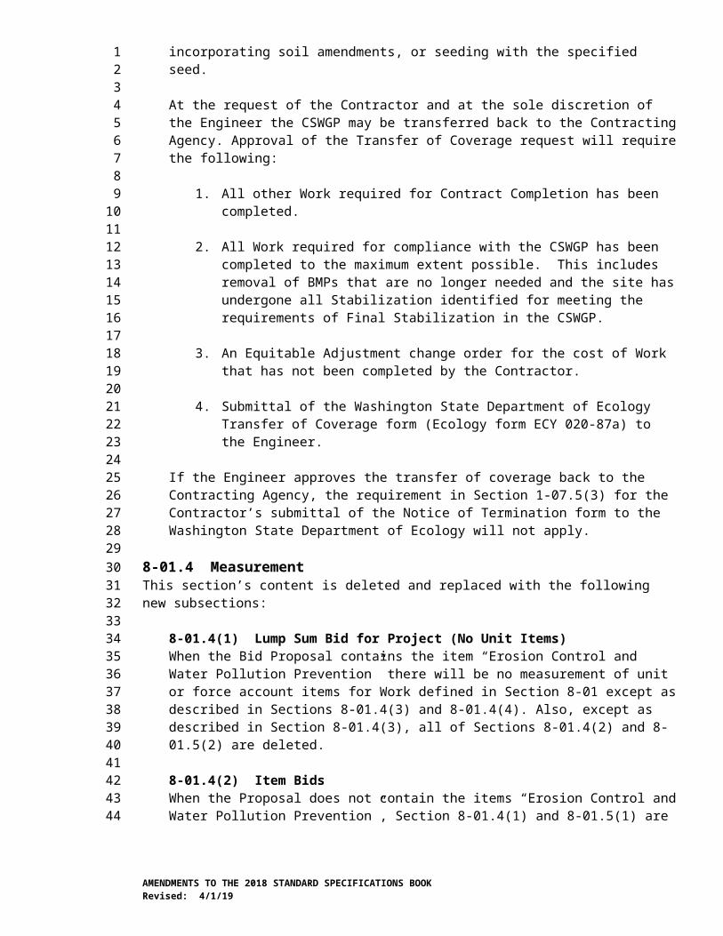
PG asphalt binder meeting the requirements of AASHTO M 332 Table 1 of the grades specified in the Contract shall be used in the production of HMA. For HMA with greater than 20 percent RAP by total weight of HMA, or any amount of RAS, the new asphalt binder, recycling agent and recovered asphalt (RAP and/or RAS) when blended in the proportions of the mix design shall meet the PG asphalt binder requirements of AASHTO M 332 Table 1 for the grade of asphalt binder specified by the Contract.
The second paragraph, including the table, is revised to read:
In addition to AASHTO M 332 Table 1 specification requirements, PG asphalt binders shall meet the following requirements:
Additional Requirements byPerformance Grade (PG) Asphalt Binders
Property Test Method
PG58S-22
PG58H-22
PG58V-22 PG64S-28 PG64H-
28PG64V-
28RTFO
Residue:Average Percent
Recovery @ 3.2 kPa
AASHTO T 3501 30% Min. 20% Min. 25% Min. 30% Min.
1Specimen conditioned in accordance with AASHTO T 240 – RTFO.
The third paragraph is revised to read:
The RTFO Jnrdiff and the PAV direct tension specifications of AASHTO M 332 are not required.
9-02.1(6) Cationic Emulsified AsphaltThis section is revised to read:
Cationic Emulsified Asphalt meeting the requirements of AASHTO M 208 Table 1 of the grades specified in the Contract shall be used.
9-02.5 Warm Mix Asphalt (WMA) AdditiveThis section, including title, is revised to read:
9-02.5 HMA AdditiveAdditives for HMA shall be accepted by the Engineer.
9-03.AP9Section 9-03, AggregatesJanuary 7, 2019
9-03.1 Aggregates for Portland Cement ConcreteThis section’s title is revised to read:
Aggregates for Concrete
AMENDMENTS TO THE 2018 STANDARD SPECIFICATIONS BOOKRevised: 4/1/19
123456789
101112
13141516171819202122232425262728293031323334
3536373839
9-03.1(1) General RequirementsThe first two sentences of the first paragraph are revised to read:
Concrete aggregates shall be manufactured from ledge rock, talus, or sand and gravel in accordance with the provisions of Section 3-01. Reclaimed aggregate may be used if it complies with the specifications for concrete.
The second paragraph (up until the colon) is revised to read:
Aggregates for concrete shall meet the following test requirements:
The second sentence of the second to last paragraph is revised to read:
The Contractor shall submit test results according to ASTM C1567 through the Engineer to the State Materials Laboratory that demonstrate that the proposed fly ash when used with the proposed aggregates and cement will control the potential expansion to 0.20 percent or less before the fly ash and aggregate sources may be used in concrete.
9-03.1(2) Fine Aggregate for Portland Cement ConcreteThis section’s title is revised to read:
Fine Aggregate for Concrete
9-03.1(4) Coarse Aggregate for Portland Cement ConcreteThis section’s title is revised to read:
Coarse Aggregate for Concrete
9-03.1(4)C GradingThe first paragraph (up until the colon) is revised to read:
Coarse aggregate for concrete when separated by means of laboratory sieves shall conform to one or more of the following gradings as called for elsewhere in these Specifications, Special Provisions, or in the Plans:
9-03.1(5) Combined Aggregate Gradation for Portland Cement ConcreteThis section’s title is revised to read:
Combined Aggregate Gradation for Concrete
9-03.1(5)B GradingIn the last paragraph, “WSDOT FOP for WAQTC/AASHTO T 27/T 11” is revised to read “FOP for WAQTC/AASHTO T 27/T 11”.
9-03.2 Aggregate for Job-Mixed Portland Cement MortarThis section’s title is revised to read:
Aggregate for Job-Mixed Portland Cement or Blended Hydraulic Cement Mortar
The first sentence of the first paragraph is revised to read:
AMENDMENTS TO THE 2018 STANDARD SPECIFICATIONS BOOKRevised: 4/1/19
123456789
101112131415161718192021222324252627282930313233343536373839404142434445464748495051

Fine aggregate for portland cement or blended hydraulic cement mortar shall consist of sand or other inert materials, or combinations thereof, accepted by the Engineer, having hard, strong, durable particles free from adherent coating.
9-03.4(1) General RequirementsThe first paragraph (up until the colon) is revised to read:
Aggregate for bituminous surface treatment shall be manufactured from ledge rock, talus, or gravel, in accordance with Section 3-01. Aggregates for Bituminous Surface Treatment shall meet the following test requirements:
9-03.8(1) General RequirementsThe first paragraph (up until the colon) is revised to read:
Aggregates for Hot Mix Asphalt shall meet the following test requirements:
9-03.8(2) HMA Test RequirementsThe two tables in the second paragraph are replaced with the following three tables:
Mix CriteriaHMA Class
3∕8 inch ½ inch ¾ inch 1 inchMin. Max. Min. Max. Min. Max. Min. Max.
Voids in Mineral Aggregate (VMA), % 15.0 14.0 13.0 12.0
Voids Filled With Asphalt (VFA), %ESAL’s (millions) VFA< 0.3 70 80 70 80 70 80 67 800.3 to < 3 65 78 65 78 65 78 65 78≥ 3 73 76 65 75 65 75 65 75Dust/Asphalt Ratio 0.6 1.6 0.6 1.6 0.6 1.6 0.6 1.6
Test Method ESAL’s (millions) Number of PassesHamburg Wheel-Track Testing, FOP for AASHTO T 324 Minimum Number of Passes with no Stripping Inflection Point and Maximum Rut Depth of 10mm
< 0.3 10,000
0.3 to < 3 12,500
≥ 3 15,000Indirect Tensile (IDT) Strength (psi) of Bituminous Materials FOP for ASTM D6931 175 Maximum
ESAL’s (millions) N initial N design N maximum
% Gmm< 0.3 ≤ 91.5 96.0 ≤ 98.0
0.3 to < 3 ≤ 90.5 96.0 ≤ 98.0≥ 3 ≤ 89.0 96.0 ≤ 98.0
Gyratory Compaction (number of gyrations)
< 0.3 6 50 750.3 to < 3 7 75 115
> 3 8 100 160
9-03.8(7) HMA Tolerances and AdjustmentsIn the table in item number 1, the fifth row is revised to read:
Asphalt binder -0.4% to 0.5% 0.7%
AMENDMENTS TO THE 2018 STANDARD SPECIFICATIONS BOOKRevised: 4/1/19
123456789
10111213141516171819
20
21
22232425
26
In the table in item number 1, the following new row is inserted before the last row:
Voids in Mineral Aggregate, VMA
-1.0%
9-03.9(1) BallastThe second paragraph (up until the colon) is revised to read:
Aggregates for ballast shall meet the following test requirements:
9-03.14(4) Gravel Borrow for Structural Earth WallThe second sentence of the first paragraph is revised to read:
The material shall be substantially free of shale or other soft, poor durability particles, and shall not contain recycled materials, such as glass, shredded tires, concrete rubble, or asphaltic concrete rubble.
9-03.21(1)B Recycled Concrete Aggregate Approval and AcceptanceThe first sentence of the second paragraph is revised to read:
Recycled concrete aggregate may be used as coarse aggregate or blended with coarse aggregate for Commercial Concrete, Class 3000 concrete, or Cement Concrete Pavement.
Item number 4 of the second paragraph is revised to read:
4. For Cement Concrete Pavement mix designs using recycled concrete aggregates, the Contractor shall submit evidence that ASR mitigating measures control expansion in accordance with Section 9-03.1(1).
This section is supplemented with the following new subsection:
9-03.21(1)B1 Recycled Concrete Aggregate Approval and AcceptanceRecycled concrete aggregate may be approved through a three tiered system that consists of the following:
Tier 1Approval Requirements Approval of the Reclamation Facility is not required.Acceptance Requirements Certification of toxicity characteristics in accordance with
Section 9-03.21(1).Field acceptance testing in accordance with Section 3-04.
Approved to provide the following Aggregate Materials:9-03.10 Aggregate for Gravel Base9-03.12(1)B Gravel Backfill for Foundations Class B9-03.12(2) Gravel Backfill for Walls9-03.12(3) Gravel Backfill for Pipe Zone Bedding9-03.14(1) Gravel Borrow9-03.14(2) Select Borrow9-03.14(2) Select Borrow (greater than 3 feet below subgrade and side slope)9-03.14(3) Common Borrow9-03.14(3) Common Borrow (greater than 3 feet below subgrade and side slope)9-03.17 Foundation Material Class A and Class B
AMENDMENTS TO THE 2018 STANDARD SPECIFICATIONS BOOKRevised: 4/1/19
12
3456789
10111213141516171819202122232425262728293031323334

9-03.18 Foundation Material Class C9-03.19 Bank Run Gravel for Trench Backfill
Tier 2Approval Requirements The Reclamation Facility shall have a Quality Control
Plan (QCP) in accordance with WSDOT QC 9 “Standard Practice for Approval of Reclamation Facilities of WSDOT Recycled Concrete and Returned Concrete”. The Reclamation Facility’s QCP shall be submitted and approved by the WSDOT State Materials Laboratory. Once accepted, any changes to the QCP will require a new QCP to be submitted for acceptance.Evaluation of aggregate source properties (LA Wear and Degradation) for the recycled concrete aggregate is not required.
Acceptance Requirements Certification of toxicity characteristics in accordance with Section 9-03.21(1), required if requested.Field acceptance testing in accordance with Section 3-04 is required.Provide certification in accordance with WSDOT QC 9 for every lot. A lot shall be no larger than 10,000 tons.
Approved to provide the following Aggregate Materials:Tier 1 aggregate materials9-03.1 Coarse Aggregate for Commercial Concrete or Concrete class 30009-03.9(1) Ballast9-03.9(2) Permeable Ballast9-03.9(3) Crushed Surfacing9-03.12(1)A Gravel Backfill for Foundations Class A
Tier 3Approval Requirements The Reclamation Facility shall have a Quality Control
Plan (QCP) in accordance with WSDOT QC 10 “Standard Practice for Approval of Reclamation Facilities of Recycled Concrete Aggregates from Stockpiles of Unknown Sources”. The Reclamation Facility’s QCP shall be submitted and approved by the WSDOT State Materials Laboratory. Once accepted, any changes to the QCP will require a new QCP to be submitted for acceptance.Evaluation of aggregate source properties (LA Wear and Degradation) for the recycled concrete aggregate is required.
Acceptance Requirements Certification of toxicity characteristics in accordance with Section 9-03.21(1) is required.Field acceptance testing in accordance with Section 3-04 is required.Provide certification in accordance with WSDOT QC 10 for every lot. A lot shall be no larger than 10,000 tons
Approved to provide the following Aggregate Materials:Tier 1 aggregate materials9-03.1 Coarse Aggregate for Commercial Concrete or Concrete class 30009-03.9(1) Ballast9-03.9(2) Permeable Ballast9-03.9(3) Crushed Surfacing9-03.12(1)A Gravel Backfill for Foundations Class A
AMENDMENTS TO THE 2018 STANDARD SPECIFICATIONS BOOKRevised: 4/1/19
1
2
For Reclamation Facilities that do not participate in Tier 2 and Tier 3, approval of recycled concrete aggregate will be in accordance with Section 9-03.21(1), and acceptance will be in accordance with Section 3-04.
9-03.21(1)E Table on Maximum Allowable percent (By Weight) of Recycled Material“Portland Cement” is deleted from the first two rows in the table.
The following new row is inserted after the second row:
Coarse Aggregate for Concrete Pavement 9-03.1(4) 0 100 0 0
The first column of the fourth row (after the preceding Amendment is applied) is revised to read:
Coarse Aggregate for Commercial Concrete and Class 3000 Concrete
9-04.AP9Section 9-04, Joint and Crack Sealing MaterialsJanuary 7, 2019
This section’s title is revised to read:
Joint Sealing Materials
9-04.1(2) Premolded Joint Filler for Expansion JointsIn this section, each reference to “AASHTO T 42” is revised to read “ASTM D 545”.
9-04.2(1)A1 Hot Poured Sealant for Cement Concrete PavementThis section is supplemented with the following:
Hot poured sealant for cement concrete pavement is acceptable for installations in joints where cement concrete pavement abuts a bituminous pavement.
9-04.2(1)A2 Hot Poured Sealant for Bituminous PavementThis section is supplemented with the following:
Hot poured sealant for bituminous pavement is acceptable for installations in joints where cement concrete pavement abuts a bituminous pavement.
9-04.2(1)B Sand Slurry for Bituminous PavementItem number 2 of the first paragraph is revised to read:
2. Two percent portland cement or blended hydraulic cement, and
9-04.3 Joint MortarThe first paragraph is revised to read:
AMENDMENTS TO THE 2018 STANDARD SPECIFICATIONS BOOKRevised: 4/1/19
123456789
1011
121314151617181920
212223242526272829303132333435363738394041424344454647
Mortar for hand mortared joints shall conform to Section 9-20.4(3) and consist of one part portland cement or blended hydraulic cement, three parts fine sand, and sufficient water to allow proper workability.
9-04.5 Flexible Plastic GasketsIn the table, the Test Method value for Specific Gravity at 77°F is revised to read “ASTM D71”.
In the table, the Test Method value for Flash Point COC, F is revised to read “ASTM D93 REV A”.
In the table, the Test Method value for Volatile Matter is revised to read “ASTM D6”.
9-05.AP9Section 9-05, Drainage Structures and CulvertsJanuary 7, 2019
9-05.3(1)A End Design and JointsThe second sentence of the first paragraph is revised to read:
The joints and gasket material shall meet the requirements of ASTM C990.
9-05.3(1)C Age at ShipmentThe last sentence of the first paragraph is revised to read:
Unless it is tested and accepted at an earlier age, it shall not be considered ready for shipment sooner than 28 days after manufacture when made with Type II portland cement or blended hydraulic cement, nor sooner than 7 days when made with Type III portland cement.
9-05.7(3) Concrete Storm Sewer Pipe JointsThe second sentence is revised to read:
The joints and gasket material shall meet the requirements of ASTM C990.
9-05.7(4)A Hydrostatic Pressure on Pipes in Straight AlignmentThe first sentence is revised to read:
Hydrostatic pressure tests on pipes in straight alignment shall be made in accordance with the procedure outlined in Section 10 of ASTM C990, except that they shall be performed on an assembly consisting of not less than three nor more than five pipe sections selected from stock by the Engineer and assembled in accordance with standard installation instructions issued by the manufacturer.
9-05.24(1) Polypropylene Culvert Pipe and Storm Sewer PipeThis section is revised to read:
Polypropylene culvert and storm sewer pipe shall conform to the following requirements:
1. For dual wall pipe sizes up to 60 inches: ASTM F2881 or AASHTO M 330, Type S or Type D.
AMENDMENTS TO THE 2018 STANDARD SPECIFICATIONS BOOKRevised: 4/1/19
123456789
10111213141516
17181920212223242526272829303132333435363738394041424344454647484950

2. For double or triple wall pipe sizes up to 60 inches: ASTM F2764.
3. Fittings shall be factory welded, injection molded, or PVC.
9-05.24(2) Polypropylene Sanitary Sewer PipeThis section is revised to read:
Polypropylene sanitary sewer pipe shall conform to the following requirements:
1. For pipe sizes up to 60 inches: ASTM F2764.
2. Fittings shall be factory welded, injection molded, or PVC.
9-06.AP9Section 9-06, Structural Steel and Related MaterialsJanuary 7, 2019
9-06.5 BoltsThis section’s title is revised to read:
Bolts and Rods
9-06.5(4) Anchor BoltsThis section, including title, is revised to read:
9-06.5(4) Anchor Bolts and Anchor RodsAnchor bolts and anchor rods shall meet the requirements of ASTM F1554 and, unless otherwise specified, shall be Grade 105 and shall conform to Supplemental Requirements S2, S3, and S4.
Nuts for ASTM F1554 Grade 105 black anchor bolts and anchor rods shall conform to ASTM A563, Grade D or DH. Nuts for ASTM F1554 Grade 105 galvanized anchor bolts and anchor rods shall conform to either ASTM A563, Grade DH, or AASHTO M292, Grade 2H, and shall conform to the overtapping, lubrication, and rotational testing requirements in Section 9-06.5(3). Nuts for ASTM F1554 Grade 36 or 55 black or galvanized anchor bolts and anchor rods shall conform to ASTM A563, Grade A or DH. Washers shall conform to ASTM F436.
The bolts and rods shall be tested by the manufacturer in accordance with the requirements of the pertinent Specification and as specified in these Specifications. Anchor bolts, anchor rods, nuts, and washers shall be inspected prior to shipping to the project site. The Contractor shall submit to the Engineer for acceptance a Manufacturer’s Certificate of Compliance for the anchor bolts, anchor rods, nuts, and washers, as defined in Section 1-06.3. If the Engineer deems it appropriate, the Contractor shall provide a sample of the anchor bolt, anchor rod, nut, and washer for testing.
All bolts, rods, nuts, and washers shall be marked and identified as required in the pertinent Specification.
AMENDMENTS TO THE 2018 STANDARD SPECIFICATIONS BOOKRevised: 4/1/19
123456789
1011121314151617
181920212223242526272829303132333435363738394041424344454647484950
9-06.15 Welded Shear ConnectorsThe third paragraph is revised to read:
Mechanical properties shall be determined in accordance with AASHTO T 244.
9-06.17 VacantThis section, including title, is revised to read:
9-06.17 Noise Barrier Wall Access DoorAccess door frames shall be formed of 14-gauge steel to the size and dimensions shown in the Plans. The access door frame head and jamb members shall be mitered, securely welded, and ground smooth. Each head shall have two anchors and each jamb shall have three anchors. The hinges shall be reinforced with ¼-inch by 12-inch plate, width equal to the full inside width of the frame.
Access doors shall be full flush 1-¾-inch thick seamless doors with a polystyrene core. Door faces shall be constructed with smooth seamless 14-gauge roller-levered, cold-rolled steel sheet conforming to ASTM A 792 Type SS, Grade 33 minimum, Coating Designation AZ55 minimum. The vertical edges shall be neat interlocked hemmed edge seam. The top and bottom of the door shall be enclosed with 14-gauge channels. Mortise and reinforcement for locks and hinges shall be 10-gauge steel. Welded top cap shall be ground and filled for exterior applications. The bottom channel shall have weep holes.
Each access door shall have three hinges. Access door hinges shall be ASTM A 276 Type 316 stainless steel, 4-½-inches square, with stainless steel ball bearing and non-removable pins.
Each access door shall have two pull plates. The pull plates shall be ASTM A 240 Type 316 stainless steel, with a grip handle of one-inch diameter and 8 to 10-inches in length.
The door assembly shall be fabricated and assembled as a complete unit including all hardware specified prior to shipment.
9-06.18 Metal Bridge RailingThe second sentence of the first paragraph is revised to read:
Steel used for metal railings, when galvanized after fabrication in accordance with AASHTO M111, shall have a controlled silicon content of either 0.00 to 0.06 percent or 0.15 to 0.25 percent.
9-07.AP9Section 9-07, Reinforcing SteelJanuary 7, 2019
9-07.5(1) Epoxy-Coated Dowel Bars (for Cement Concrete Rehabilitation)This section (including title) is revised to read:
9-07.5(1) Dowel Bars for Cement Concrete Pavement RehabilitationDowel bars for Cement Concrete Pavement Rehabilitation shall be 1½ inch outside diameter plain round steel bars or tubular bars 18 inches in length and meet the requirements of one of the following dowel bar types:
AMENDMENTS TO THE 2018 STANDARD SPECIFICATIONS BOOKRevised: 4/1/19
123456789
1011121314151617181920212223242526272829303132333435363738394041424344
45464748495051
1. Epoxy-coated dowel bars shall be round plain steel bars of the dimensions shown in the Standard Plans. They shall conform to AASHTO M31, Grade 60 or ASTM A615, Grade 60 and shall be coated in accordance with ASTM A1078 Type 2 coating, except that the bars may be cut to length after being coated. Cut ends shall be coated in accordance with ASTM A1078 with a patching material that is compatible with the coating, inert in concrete and recommended by the coating manufacturer. The thickness of the epoxy coating shall be 10 mils plus or minus 2 mils. The Contractor shall furnish a written certification that properly identifies the coating material, the number of each batch of coating material used, quantity represented, date of manufacture, name and address of manufacturer, and a statement that the supplied coating material meets the requirements of ASTM A1078 Type 2 coating. Patching material, compatible with the coating material and inert in concrete and recommended by the manufacturer shall be supplied with each shipment for field repairs by the Contractor.
2. ASTM A513 steel tubes made from Grade 60 Carbon Steel Tube with a 1.625 inch outside diameter and a 0.120 inch wall thickness. Both the inside and outside of the tube shall be zinc coated with G40 galvanizing in accordance with ASTM A653. Following zinc coating the tubes shall be coated in accordance with Section 9-07.5(1) item 1. The ends of the tube shall be capped to prevent intrusion of concrete or other materials.
9-07.5(2) Corrosion Resistant Dowel Bars (for Cement Concrete Pavement and Cement Concrete Pavement Rehabilitation)The first paragraph (up until the colon) is revised to read:
Corrosion resistant dowel bars shall be 1½ inch outside diameter plain round steel bars or tubular bars 18 inches in length and meet the requirements of one of the following:
Item number 4 and 5 of the first paragraph are revised to read:
4. Corrosion-resistant, low-carbon, chromium plain steel bars for concrete reinforcement meeting all the requirements of ASTM A 1035 Alloy Type CS Grade 100 or Alloy Type CS Grade 120.
5. Zinc Clad dowel bars shall be 1½ inch solid bars or 1.625 inch outside diameter by 0.120 inch wall tubular bars meeting the chemical and physical properties of AASHTO M 31, Grade 60, or AASHTO M 255, Grade 60. The bars shall have a minimum of 0.035 inches A710 Zinc alloy clad to the plain steel inner bar or tube. A710 Zinc shall be composed of: zinc: 99.5 percent, by weight, minimum; copper: 0.1-0.25 percent, by weight; and iron: 0.0020 percent, by weight, maximum. Each end of tubular bars shall be plugged using a snug-fitting insert to prohibit any intrusion of concrete or other materials.
The numbered list in the first paragraph is supplemented with the following:
6. Multicoated fusion bonded epoxy bars shall consist of an ASTM A615 bar with alternating layers of ASTM A934 coating and an abrasion resistant overcoat (ARO). The ASTM A934 coating shall form the base and there shall be two layers of each coating material. The minimum thickness of the combined layers of the ASTM A934
AMENDMENTS TO THE 2018 STANDARD SPECIFICATIONS BOOKRevised: 4/1/19
123456789
10111213141516171819202122232425262728293031323334353637383940414243444546474849505152
coating and ARO coating shall be 20 mils. The ARO shall meet the following requirements:
Test Method SpecificationGouge Resistance NACE TM0215, 30 kg wt., LS-1 bit @ 25°C < 0.22 mmGouge Resistance NACE TM0215, 50 kg wt., LS-1 bit @ 25°C < 0.44 mm
7. ASTM A513 steel tubes made from Grade 60 Carbon Steel Tube with a 1.625 inch outside diameter and a 0.120 inch wall thickness. Both the inside and outside of the tube shall be zinc coated with G90 galvanizing in accordance with ASTM A653. Following zinc coating the tubes shall be coated in accordance with Section 9-07.5(1) item 1. The ends of the tube shall be capped to prevent intrusion of concrete or other materials.
The last paragraph is revised to read:
Stainless Steel Clad and Stainless Steel Tube Dowel bar ends shall be sealed with a patching material (primer and finish coat) used for patching epoxy-coated reinforcing steel as required in Section 9-07.3, item 6.
9-07.7 Wire MeshThis section is supplemented with the following:
Welded wire manufacturers shall participate in the NTPEP Audit Program for Reinforcing Steel (rebar) Manufacturers and shall be listed on the NTPEP audit program website displaying that they are NTPEP compliant.
9-08.AP9Section 9-08, Paints and Related MaterialsJanuary 7, 2019
9-08.1(1) DescriptionThe first sentence is revised to read:
Paint used for highway and bridge structure applications shall be made from materials meeting the requirements of the applicable Federal and State Paint Specifications, Department of Defense (DOD), American Society of Testing of Materials (ASTM), and The Society for Protective Coatings (SSPC) specifications in effect at time of manufacture.
9-08.1(2) Paint TypesThis section is supplemented with the following new subsections:
9-08.1(2)M NEPCOAT Qualified Products List AQualified products used shall be part of a NEPCOAT system supplied by the same manufacturer.
9-08.1(2)N NEPCOAT Qualified Products List BQualified products used shall be part of a NEPCOAT system supplied by the same manufacturer.
AMENDMENTS TO THE 2018 STANDARD SPECIFICATIONS BOOKRevised: 4/1/19
123
456789
101112131415161718192021222324252627
2829303132333435363738394041424344454647
9-08.1(2)D Organic Zinc-Rich PrimerThis section, including title, is revised to read:
Vacant
9-08.1(2)E Epoxy PolyamideThis section is revised to read:
Epoxy polyamide shall be a two-component system conforming to MIL-DTL-24441 or SSPC Coating Standard No. 42.
9-08.1(2)H Top Coat, Single-Component, Moisture-Cured PolyurethaneThis section is revised to read:
Vehicle Type: Moisture-cured aliphatic polyurethane.
Color and Gloss: Meet the SAE AMS Standard 595 Color as specified in the table below.
The Top Coat shall meet the following requirements:
The resin shall be an aliphatic urethane.
Minimum-volume solids 50 percent.
The top coat shall be semi-gloss.
Color Semi-GlossWashington Gray 26357Mt. Baker Gray 26134Mt. St. Helens Gray 26306Cascade Green 24158
9-08.1(2)I Rust-Penetrating SealerThis section is revised to read:
Rust-penetrating sealer shall be a two-component, chemically-cured, 100 percent solids epoxy.
9-08.1(2)J Black EnamelThis section is revised to read:
The enamel shall conform to Federal Specification MIL PRF 24635E Type II Class 2.
9-08.1(2)K Orange Equipment EnamelThe first paragraph is revised to read:
The enamel shall be an alkyd gloss enamel conforming to Federal Specification MIL-PRF-24635E Type II Class 1. The color, when dry, shall match that of SAE AMS Standard 595, color number 12246.
AMENDMENTS TO THE 2018 STANDARD SPECIFICATIONS BOOKRevised: 4/1/19
123456789
101112131415161718192021222324252627
28293031323334353637383940414243444546
9-08.1(2)L Exterior Acrylic Latex Paint-WhiteThe first paragraph is revised to read:
This paint shall conform to Federal Specification MIL-PRF-24635E Type II Class 1, 2 or 3.
9-08.1(7) AcceptanceThis section is revised to read:
For projects with moisture-cured polyurethane quantities less than 20 gallons, acceptance will be by the Manufacturer’s Certificate of Compliance.
For projects with moisture-cured polyurethane quantities greater than 20 gallons, the product shall be listed in the current WSDOT Qualified Products List (QPL). If the lot number is listed on the QPL, it may be accepted without additional testing. If the lot number is not listed on the QPL, a 1 quart sample shall be submitted to the State Materials Laboratory for testing and acceptance.
For all other paint types, acceptance will be based on visual inspection.
9-08.1(8) Standard ColorsIn the first paragraph, the reference to “Federal Standard 595” is revised to read “SAE AMS Standard 595”.
The second paragraph is revised to read:
Unless otherwise specified, all top or finish coats shall be semi-gloss, with the paint falling within the range of 35 to 70 on the 60-degree gloss meter.
9-08.2 Powder Coating Materials for Coating Galvanized SurfacesThe last paragraph is revised to read:
Repair materials shall be as recommended by the powder coating manufacturer and as specified in the Contractor’s powder coating plan as accepted by the Engineer.
9-08.3 Pigmented Sealer Materials for Coating of Concrete SurfacesThis section, including title, is revised to read:
9-08.3 Concrete Surface Treatments9-08.3(1) Pigmented Sealer MaterialsThe pigmented sealer shall be a semi-opaque, colored toner containing only methyl methacrylate-ethyl acrylate copolymer resins, toning pigments suspended in solution at all times by a chemical suspension agent, and solvent. Toning pigments shall be laminar silicates, titanium dioxide, and inorganic oxides only. There shall be no settling or color variation. Tinting shall occur at the factory at the time of manufacture and placement in containers, prior to initial shipment. Use of vegetable or marine oils, paraffin materials, stearates, or organic pigments in any part of coating formulation will not be permitted. The color of pigmented sealer shall be as specified by the Contracting Agency. The Contractor shall submit a 1-quart wet sample, a drawdown color sample, and spectrophotometer or colorimeter readings taken in accordance with ASTM D2244, for each batch and corresponding standard color card. The calculated Delta E shall not exceed 1.5 from the
AMENDMENTS TO THE 2018 STANDARD SPECIFICATIONS BOOKRevised: 4/1/19
123456789
10111213141516171819202122232425262728293031323334353637383940414243444546474849505152
Commission Internationale de l’Eclairage (CIELAB) when measured at 10 degrees Standard Observer and Illuminant D 65.
The 1-quart wet sample shall be submitted in the manufacturer’s labeled container with product number, batch number, and size of batch. The companion drawdown color sample shall be labeled with the product number, batch number, and size of batch. The Contractor shall submit the specified samples and readings to the Engineer at least 14 calendar days prior to the scheduled application of the sealer. The Contractor shall not begin applying pigmented sealer until receiving the Engineer’s written approval of the pigmented sealer color samples.
9-08.3(2) Exposed Aggregate Concrete Coatings and Sealers9-08.3(2)A Retardant CoatingRetardant coating shall exhibit the following properties:
1. Retards the set of the surface mortar of the concrete without preventing the concrete to reach the specified 28 day compressive strength.
2. Leaves the aggregate with its original color and luster, and firmly embedded in the concrete matrix.
3. Allows the removal of the surface mortar in accordance with the methods specified in Section 6-02.3(14)E without the use of acidic washing compounds.
4. Allows for uniform removal of the surface mortar.
If the Contractor proposes use of a retardant coating that is not listed in the current WSDOT QPL, the Contractor shall submit a Type 2 Working Drawing consisting of a one quart product sample from a current lot along with supporting product information, Safety Data Sheet, and a Manufacturer’s Certificate of Compliance stating that the product conforms to the above performance requirements.
9-08.3(2)B Clear SealerThe sealer for concrete surfaces with exposed aggregate finish shall be a clear, non-gloss, penetrating sealer of either a silane, siloxane, or silicone based formulation.
9-08.3(3) Permeon TreatmentPermeon treatment shall be a product of known consistent performance in producing the SAE AMS Standard 595 Color No. 30219 target color hue established by WSDOT, either selected from the WSDOT Qualified Products List (QPL), or an equivalent product accepted by the Engineer. For acceptance of products not listed in the current WSDOT QPL, the Contractor shall submit Type 3 Working Drawings consisting of a one quart product sample from a current lot, supporting product information and a Safety Data Sheet.
AMENDMENTS TO THE 2018 STANDARD SPECIFICATIONS BOOKRevised: 4/1/19
123456789
10111213141516171819202122232425262728293031323334353637383940414243444546474849
9-13.AP9Section 9-13, Riprap, Quarry Spalls, Slope Protection, and Rock for Erosion and Scour Protection and Rock WallsApril 2, 2018
9-13.1(1) GeneralThe last paragraph is revised to read:
Riprap and quarry spalls shall be free from segregation, seams, cracks, and other defects tending to destroy its resistance to weather and shall meet the following test requirements:
9-13.5 Concrete Slope ProtectionThis section is revised to read:
Concrete slope protection shall consist of reinforced portland cement or blended hydraulic cement concrete poured or pneumatically placed upon the slope with a rustication joint pattern or semi-open concrete masonry units placed upon the slope closely adjoining each other.
9-13.5(2) Poured Portland Cement Concrete Slope ProtectionThis section’s title is revised to read:
Poured Portland Cement or Blended Hydraulic Cement Concrete Slope Protection
9-13.5(3) Pneumatically Placed Portland Cement Concrete Slope ProtectionThis section’s title is revised to read:
Pneumatically Placed Portland Cement or Blended Hydraulic Cement Concrete Slope Protection
The first paragraph is revised to read:
Cement – This material shall be portland cement or blended hydraulic cement as specified in Section 9-01.
9-13.7(1) Rock for Rock Walls and Chinking MaterialThe first paragraph (up until the colon) is revised to read:
Rock for rock walls and chinking material shall be hard, sound and durable material,free from seams, cracks, and other defects tending to destroy its resistance to weather,and shall meet the following test requirements:
9-14.AP9Section 9-14, Erosion Control and Roadside PlantingAugust 6, 2018
9-14.4(2) Hydraulically Applied Erosion Control Products (HECPs)In Table 1, the last four rows are deleted.
AMENDMENTS TO THE 2018 STANDARD SPECIFICATIONS BOOKRevised: 4/1/19
1234
56789
101112131415161718192021222324252627282930313233343536373839404142434445
464748

9-14.4(2)A Long-Term MulchThe first paragraph is supplemented with the following:
Products containing cellulose fiber produced from paper or paper components will not be accepted.
Table 2 is supplemented with the following new rows:
Water Holding Capacity ASTM D 7367 800 percent minimumOrganic Matter Content AASHTO T 267 90 percent minimumSeed Germination Enhancement
ASTM D 7322 Long Term420 percent minimum
9-14.4(2)B Moderate-Term MulchThis section is revised to read:
Within 48 hours of application, the Moderate-Term Mulch shall bond with the soil surface to create a continuous, absorbent, flexible, erosion-resistant blanket. Moderate-Term Mulch shall effectively perform the intended erosion control function in accordance with Section 8-01.3(1) for a minimum of 3 months, or until temporary vegetation has been established, whichever comes first.
Moderate-Term Mulch shall not be used in conjunction with permanent seeding.
9-14.4(2)C Short-Term MulchThis section is revised to read:
Short-Term Mulch shall effectively perform the intended erosion control function in accordance with Section 8-01.3(1) for a minimum of 2 months, or until temporary vegetation has been established, whichever comes first. Short-Term Mulch shall not be used in conjunction with permanent seeding.
9-16.AP9Section 9-16, Fence and GuardrailAugust 6, 2018
9-16.3(1) Rail ElementThe last sentence of the first paragraph is revised to read:
All rail elements shall be formed from 12-gage steel except for thrie beam reducer sections, reduced length thrie beam rail elements, thrie beams used for bridge rail retrofits, and Design F end sections, which shall be formed from 10-gage steel.
9-16.3(5) AnchorsThe last paragraph is revised to read:
Cement grout shall conform to Section 9-20.3(4) and consist of one part portland cement or blended hydraulic cement and two parts sand.
AMENDMENTS TO THE 2018 STANDARD SPECIFICATIONS BOOKRevised: 4/1/19
12345678
91011121314151617181920212223242526272829303132
33343536373839404142434445
9-18.AP9Section 9-18, Precast Traffic CurbApril 2, 2018
9-18.1(1) Aggregates and ProportioningItem number 1 of the first paragraph is revised to read:
1. Portland cement or blended hydraulic cement shall conform to the requirements of Section 9-01 except that it may be Type I portland cement conforming to AASHTO M 85.
9-20.AP9Section 9-20, Concrete Patching Material, Grout, and MortarApril 1, 2019
9-20.1 Patching MaterialThis section, including title, is revised to read:
9-20.1 Patching Material for Cement Concrete PavementConcrete patching material shall be prepackaged mortar extended with aggregate. The amount of aggregate for extension shall conform to the manufacturer’s recommendation.
Patching mortar and patching mortar extended with aggregate shall contain cementitious material and conform to Sections 9-20.1(1) and 9-20.1(2). The Manufacturer shall use the services of a laboratory that has an equipment calibration verification system and a technician training and evaluation process in accordance with AASHTO R 18 to perform all tests specified in Section 9-20.1.
9-20.1(1) Patching MortarPatching mortar shall conform to the following requirements:
Compressive Strength ASTM Test Method Specificationat 3 hours C 39 Minimum 3,000 psiat 24 hours C 39 Minimum 5,000 psiLength Changeat 28 days C 157 0.15 percent maximumTotal Chloride Ion Content C 1218 1 lb/yd3 maximumBond Strengthat 24 hours C 882 (As modified by C
928, Section 9.5)Minimum 1,000 psi
Scaling Resistance (at 25 cycles of freezing and thawing)
C 672 (As modified by C 928, Section 9.4)
1 lb/ft2 maximum
9-20.1(2) Patching Mortar Extended with AggregatePatching mortar extended with aggregate shall meet the following requirements:
Compressive Strength ASTM Test Method Specificationat 3 hours C 39 Minimum 3,000 psiat 24 hours C 39 Minimum 5,000 psiLength Change
AMENDMENTS TO THE 2018 STANDARD SPECIFICATIONS BOOKRevised: 4/1/19
123
456789
10111213
1415161718192021222324252627282930
31323334

at 28 days C 157 0.15 percent maximumBond Strengthat 24 hours C 882 (As modified by
ASTM C928, Section 9.5)Minimum 1,000 psi
Scaling Resistance (at 25 cycles of freezing and thawing)
C 672 2 Maximum Visual Rating
Freeze thaw C 666 Maximum expansion 0.10%Minimum durability 90.0%
9-20.1(3) AggregateAggregate used to extend the patching mortar shall conform to Section 9-03.1(4) and be AASHTO Grading No. 8. A Manufacturer’s Certificate of Compliance shall be submitted showing the aggregate source and the gradation. Mitigation for Alkali Silica Reaction (ASR) will not be required for the extender aggregate used for concrete patching material.
9-20.1(4) WaterWater shall meet the requirements of Section 9-25.1. The quantity of water shall be within the limits recommended by the repair material manufacturer.
9-20.2 SpecificationsThis section, including title, is revised to read:
9-20.2 Patching Material for Concrete Structure RepairConcrete patching material shall be a prepackaged mixture of portland or blended hydraulic cement, aggregate, and admixtures. Fly ash, ground granulated blast furnace slag and microsilica fume may be used. The concrete patching material may be shrinkage compensated. The concrete patching material shall also meet the following requirements:
• Compressive strength of 6000 psi or higher at 28 days in accordance with AASHTO T 22 (ASTM C 39), unless noted otherwise
• Bond strength of 250 psi or higher at 28 days or less in accordance with ASTM C 1583 or ICRI 210.3R
• Shrinkage shall be 0.05 percent (500 microstrain) or lower at 28 days in accordance with AASHTO T 160 (ASTM C 157) as modified by ICRI 320.3R
• Permeability shall be 2,000 coulombs or lower at 28 days in accordance with AASHTO T 277 (ASTM C 1202)
• Freeze-thaw resistance shall have a durability factor of 90 percent or higher after a minimum of 300 cycles in accordance with AASHTO T 161 Procedure A (ASTM C 666)
• Soluble chloride ion limits in Section 6-02.3(2) shall be satisfied
9-20.2(1) Patching MortarThis section, including title, is deleted in its entirety.
AMENDMENTS TO THE 2018 STANDARD SPECIFICATIONS BOOKRevised: 4/1/19
123456789
10111213141516171819202122232425262728293031323334353637383940414243

9-20.2(2) Patching Mortar Extended with AggregateThis section, including title, is deleted in its entirety.
9-20.3(3) Grout Type 3 for Unconfined Bearing Pad ApplicationsThis section’s title is revised to read:
Grout Type 3 for Unconfined Applications
This section is revised to read:
Grout Type 3 shall be a prepackaged material that does not include expansive admixtures meeting the following requirements:
• Compressive strength shall be 4000 psi or higher at 28 days in accordance with AASHTO T 22 (ASTM C 39) for grout extended with coarse aggregate or AASHTO T 106 (ASTM C109) otherwise.
• Bond strength shall meet one of the following:
◦ 250 psi or higher at 28 days or less in accordance with ASTM C1583.
◦ 2000 psi or higher at 28 days or less in accordance with ASTM C882. The following modification to ASTM C882 is acceptable: use Type 3 Grout in lieu of epoxy resin base bonding system and freshly mixed portland-cement mortar in the procedure for testing Type II and V systems.
• Drying shrinkage shall be 0.08 percent (800 microstrain) or lower at 28 days in accordance with AASHTO T 160 (ASTM C157). The following modification to AASHTO T 160 is acceptable: use a standard specimen size of 3 x 3 x 11-¼ inches.
9-20.5 Bridge Deck Repair MaterialItem number 3 of the first paragraph is revised to read:
3. Permeability of less than 2,000 coulombs at 28-days or more in accordance with AASHTO T 277.
9-21.AP9Section 9-21, Raised Pavement Markers (RPM)January 2, 2018
9-21.2 Raised Pavement Markers Type 2This section’s content is deleted.
9-21.2(1) Physical PropertiesThis section, including title, is revised to read:
9-21.2(1) Standard Raised Pavement Markers Type 2The marker housing shall contain reflective faces as shown in the Plans to reflect incident light from either a single or opposite directions and meet the requirements of ASTM D 4280 including Flexural strength requirements.
AMENDMENTS TO THE 2018 STANDARD SPECIFICATIONS BOOKRevised: 4/1/19
123456789
10111213141516171819202122232425262728293031323334353637383940
4142434445464748495051
9-21.2(2) Optical RequirementsThis section, including title, is revised to read:
9-21.2(2) Abrasion Resistant Raised Markers Type 2Abrasion Resistant Raised Markers Type 2 shall comply with Section 9-21.2(1) and meet the requirements of ASTM D 4280 with the following additional requirement: The coefficient of luminous intensity of the markers shall be measured after subjecting the entire lens surface to the test described in ASTM D 4280 Section 9.5 using a sand drop apparatus. After the exposure described above, retroreflected values shall not be less than 0.5 times a nominal unblemished sample.
9-21.2(3) Strength RequirementsThis section is deleted in its entirety.
9-23.AP9Section 9-23, Concrete Curing Materials and AdmixturesApril 1, 2019
9-23.12 Natural PozzolanThis section is revised to read:
Natural Pozzolans shall be ground Pumice and shall conform to the requirements of AASHTO M295 Class N, including supplementary optional chemical requirements as set forth in Table 2.
9-23.13 Blended Supplementary Cementitious MaterialThe second sentence is revised to read:
Blended SCMs shall be limited to binary or ternary blends of fly ash, ground granulated blast furnace slag and microsilica fume.
The second to last sentence is deleted.
9-26.AP9Section 9-26, Epoxy ResinsJanuary 7, 2019
9-26.1(1) GeneralThe following new sentence is inserted after the first sentence of the first paragraph:
For pre-packaged cartridge kits, the epoxy bonding agent shall meet the requirements of ASTM C881 when mixed according to manufacturer instructions, utilizing the manufacturer’s mixing nozzle.
9-26.1(2) Packaging and MarkingThe first sentence of the first paragraph is revised to read:
The components of the epoxy system furnished under these Specifications shall be supplied in separate containers or pre-packaged cartridge kits that are non-reactive with the materials contained.
AMENDMENTS TO THE 2018 STANDARD SPECIFICATIONS BOOKRevised: 4/1/19
123456789
1011121314151617
181920212223242526272829303132333435
3637383940414243444546474849
The second paragraph is revised to read:
Separate containers shall be marked by permanent marking that identify the formulator, “Component A” (contains the Epoxy Resin) and “Component B” (Contains the Curing Agent), type, grade, class, lot or batch number, mixing instructions and the quantity contained in pounds or gallons as defined by these Specifications.
The following new paragraph is inserted after the second paragraph:
Pre-packaged cartridge kits shall be marked by permanent marking that identify the formulator, type, grade, class, lot or batch number, mixing instructions and the quantity contained in ounces or milliliters as defined by these Specifications.
9-28.AP9Section 9-28, Signing Materials and FabricationApril 1, 2019
9-28.2 Manufacturer’s Identification and DateThe second sentence is revised to read:
In addition, the width and height dimension, in inches, the Contract number, and the number of the sign as it appears in the Plans shall be placed using 3-inch series C black letters on the back of destination, distance, and large special signs.
9-28.10 VacantThis section, including title, is revised to read:
9-28.10 Digital PrintingTransparent and opaque durable inks used in digital printed sign messages shall be as recommended by the manufacturer. When properly applied, digital printed colors shall have a warranty life of the base retroreflective sign sheeting. Digital applied colors shall present a smooth surface, free from foreign material, and all messages and borders shall be clear and sharp. Digital printed signs shall conform to 70% of the retroreflective minimum values established for its type and color. Digitally printed signs shall meet the daytime color and luminance, and nighttime color requirements of ASTM D 4956. No variations in color or overlapping of colors will be permitted. Digital printed permanent traffic signs shall have an integrated engineered match component clear protective overlay recommended by the sheeting manufacturer applied to the entire face of the sign. On Temporary construction/maintenance signs printed with black ink only, the protective overlay film is optional, as long as the finished sign has a warranty of a minimum of three years from sign sheeting manufacturer.
All digital printed traffic control signs shall be an integrated engineered match component system. The integrated engineered match component system shall consist of retroreflective sheeting, durable ink(s), and clear overlay film all from the same manufacturer applied to aluminum substrate conforming to Section 9-28.8.
The sign fabricator shall use an approved integrated engineered match component system as listed on the Qualified Products List (QPL). Each approved digital printer shall only use the compatible retroreflective sign sheeting manufacturer’s engineered match component system products.
AMENDMENTS TO THE 2018 STANDARD SPECIFICATIONS BOOKRevised: 4/1/19
123456789
10111213141516
1718192021222324252627282930313233343536373839404142434445464748495051

Each retroreflective sign sheeting manufacturer/integrated engineered match component system listed on the QPL shall certify a department approved sign fabricator is approved to operate their compatible digital printer. The sign fabricator shall re-certify annually with the retroreflective sign manufacturer to ensure their digital printer is still meeting manufacturer’s specifications for traffic control signs. Documentation of each re-certification shall be submitted to the QPL Engineer annually.
9-28.11 HardwareThe last paragraph is revised to read:
All steel parts shall be galvanized in accordance with AASHTO M111. Steel bolts and related connecting hardware shall be galvanized in accordance with ASTM F 2329.
9-28.14(2) Steel Structures and PostsThe first sentence of the third paragraph is revised to read:
Anchor rods for sign bridge and cantilever sign structure foundations shall conform to Section 9-06.5(4), including Supplemental Requirement S4 tested at -20°F.
In the second sentence of the fourth paragraph, “AASHTO M232” is revised to read “ASTM F 2329”.
The first sentence of the fifth paragraph is revised to read:
Except as otherwise noted, steel used for sign structures and posts shall have a controlled silicon content of either 0.00 to 0.06 percent or 0.15 to 0.25 percent.
The last sentence of the last paragraph is revised to read:
If such modifications are contemplated, the Contractor shall submit a Type 2 Working Drawing of the proposed modifications.
9-29.AP9Section 9-29, Illumination, Signal, ElectricalApril 1, 2019
9-29.1 Conduit, Innerduct, and OuterductThis section is supplemented with the following new subsections:
9-29.1(10) Pull TapePull tape shall be pre-lubricated polyester pulling tape. The pull tape shall have a minimum width of ½-inch and a minimum tensile strength of 500 pounds. Pull tape may have measurement marks.
9-29.1(11) Foam Conduit SealantFoam conduit sealant shall be self-expanding waterproof foam designed to prevent both water and pest intrusion. The foam shall be designed for use in and around electrical equipment, including both insulated and bare conductors.
9-29.2(1) Junction BoxesThe first paragraph is revised to read:
AMENDMENTS TO THE 2018 STANDARD SPECIFICATIONS BOOKRevised: 4/1/19
123456789
1011121314151617181920212223242526272829303132333435
36373839404142434445464748495051

For the purposes of this Specification concrete is defined as portland cement or blended hydraulic cement concrete and non-concrete is all others.
9-29.2(1)A2 Non-Concrete Junction BoxesThe first paragraph is revised to read:
Material for the non-concrete junction boxes shall be of a quality that will provide for a similar life expectancy as portland cement or blended hydraulic cement concrete in a direct burial application.
9-29.2(2)A Standard Duty Cable Vaults and Pull BoxesIn the table in the last paragraph, the fourth, fifth and sixth rows are revised to read:
Slip Resistant Lid ASTM A36 steelFrame ASTM A36 steelSlip Resistant Frame ASTM A36 steel
9-29.3(2)A1 Single Conductor Current CarryingThis second sentence is revised to read:
Insulation shall be XLP (cross-linked polyethylene) or EPR (Ethylene Propylene Rubber), Type USE (Underground Service Entrance) or USE-2, and rated for 600-volts or higher.
9-29.6 Light and Signal StandardsIn the first sentence of the third paragraph, “AASHTO M232” is revised to read “ASTM F 2329”.
Item number 2 of the last paragraph is revised to read:
2. The steel light and signal standard fabricator’s shop drawing submittal, including supporting design calculations, submitted as a Type 2E Working Drawing in accordance with Section 8-20.2(1) and the Special Provisions.
9-29.6(1) Steel Light and Signal StandardsIn the second paragraph, “AASHTO M232” is revised to read “ASTM F 2329”.
The first sentence of the last paragraph is revised to read:
Steel used for light and signal standards shall have a controlled silicon content of either 0.00 to 0.06 percent or 0.15 to 0.25 percent.
9-29.6(5) Foundation HardwareIn the last paragraph, “AASHTO M232” is revised to read “ASTM F 2329”.
9-29.10(1) Conventional Roadway LuminairesThis section is revised to read:
All conventional roadway luminaires shall meet 3G vibration requirements as described in ANSI C136.31.
AMENDMENTS TO THE 2018 STANDARD SPECIFICATIONS BOOKRevised: 4/1/19
123456789
10111213
1415161718192021222324252627282930313233343536373839404142434445464748
All luminaires shall have housings fabricated from aluminum. The housing shall be painted flat gray, SAE AMS Standard 595 color chip No. 26280, unless otherwise specified in the Contract. Painted housings shall withstand a 1,000 hour salt spray test as specified in ASTM B117.
Each housing shall include a four bolt slip-fitter mount capable of accepting a nominal 2” tenon and adjustable within +/- 5 degrees of the axis of the tenon. The clamping bracket(s) and the cap screws shall not bottom out on the housing bosses when adjusted within the +/- 5 degree range. No part of the slipfitter mounting brackets on the luminaires shall develop a permanent set in excess of 0.2 inch when the cap screws used for mounting are tightened to a torque of 32 foot-pounds. Each luminaire shall include leveling reference points for both transverse and longitudinal adjustment.
All luminaires shall include shorting caps when shipped. The caps shall be removed and provided to the Contracting Agency when an alternate control device is required to be installed in the photocell socket. House side shields shall be included when required by the Contract. Order codes shall be modified to the minimum extent necessary to include the option for house side shields.
This section is supplemented with the following new subsections:
9-29.10(1)A High Pressure Sodium (HPS) Conventional Roadway LuminairesHPS conventional roadway luminaires shall meet the following requirements:
1. General shape shall be “cobrahead” style, with flat glass lens and full cutoff optics.
2. Light pattern distribution shall be IES Type III.
3. The reflector of all luminaires shall be of a snap-in design or secured with screws. The reflector shall be polished aluminum or prismatic borosilicate glass.
4. Flat lenses shall be formed from heat resistant, high-impact, molded borosilicate or tempered glass.
5. The lens shall be mounted in a doorframe assembly, which shall be hinged to the luminaire and secured in the closed position to the luminaire by means of an automatic latch. The lens and doorframe assembly, when closed, shall exert pressure against a gasket seat. The lens shall not allow any light output above 90 degrees nadir. Gaskets shall be composed of material capable of withstanding the temperatures involved and shall be securely held in place.
6. The ballast shall be mounted on a separate exterior door, which shall be hinged to the luminaire and secured in the closed position to the luminaire housing by means of an automatic type of latch (a combination hex/slot stainless steel screw fastener may supplement the automatic-type latch).
7. Each luminaire shall be capable of accepting a 150, 200, 250, 310, or 400 watt lamp complete and associated ballast. Lamps shall mount horizontally.
AMENDMENTS TO THE 2018 STANDARD SPECIFICATIONS BOOKRevised: 4/1/19
123456789
101112131415161718192021222324252627282930313233343536373839404142434445464748495051
9-29.10(1)B Light Emitting Diode (LED) Conventional Roadway LuminairesLED Conventional Roadway Luminaires are divided into classes based on their equivalent High Pressure Sodium (HPS) luminaires. Current classes are 200W, 250W, 310W, and 400W. LED luminaires are required to be pre-approved in order to verify their photometric output. To be considered for pre-approval, LED luminaires must meet the requirements of this section.
LED luminaires shall include a removable access door, with tool-less entry, for access to electronic components and the terminal block. The access door shall be removable, but include positive retention such that it can hang freely without disconnecting from the luminaire housing. LED drivers may be mounted either to the interior of the luminaire housing or to the removable door itself.
LED drivers shall be removable for user replacement. All internal modular components shall be connected by means of mechanical plug and socket type quick disconnects. Wire nuts may not be used for any purpose. All external electrical connections to the luminaire shall be made through the terminal block.
LED luminaires shall include a 7-pin NEMA photocell receptacle. The LED driver(s) shall be dimmable from ten volts to zero volts. LED output shall have a Correlated Color Temperature (CCT) of 4000K nominal (4000-4300K) and a Color Rendering Index (CRI) of 70 or greater. LED output shall be a minimum of 85% at 75,000 hours at 25 degrees Celsius.
LED luminaires shall be available for 120V, 240V, and 480V supply voltages. Voltages refer to the supply voltages to the luminaires present in the field. LED power usage shall not exceed the following maximum values for the applicable wattage class:
Class Max. Wattage200W 110W250W 165W310W 210W400W 275W
Only one brand of LED conventional roadway luminaire may be used on a Contract. They do not necessarily have to be the same brand as any high-mast, underdeck, or wall-mount luminaires when those types of luminaires are specified in the Contract. LED luminaires shall include a standard 10 year manufacturer warranty.
The list of pre-approved LED Conventional Roadway Luminaires is available at http://www.wsdot.wa.gov/Design/Traffic/ledluminaires.htm.
9-29.10(2) Decorative LuminairesThis section, including title, is revised to read:
9-29.10(2) Vacant
9-29.12 Electrical Splice MaterialsThis section is supplemented with the following new subsections:
AMENDMENTS TO THE 2018 STANDARD SPECIFICATIONS BOOKRevised: 4/1/19
123456789
10111213141516171819202122232425262728
2930313233343536373839404142434445

9-29.12(3) Splice Enclosures9-29.12(3)A Heat Shrink Splice EnclosureHeat shrink splice enclosures shall be medium or heavy wall cross-linked polyolefin, meeting the requirements of AMS-DTL-23053/15, with thermoplastic adhesive sealant. Heat shrink splices used for “wye” connections require rubber electrical mastic tape.
9-29.12(3)B Molded Splice EnclosureMolded splice enclosures shall use epoxy resin in a clear rigid plastic mold. The material used shall be compatible with the insulation material of the insulated conductor or cable. The component materials of the resin insulation shall be packaged ready for convenient mixing without removing from the package.
9-29.12(4) Re-Enterable Splice EnclosureRe-enterable splice enclosures shall use either dielectric grease or a flexible resin contained in a two-piece plastic mold. The mold shall either snap together or use stainless steel hose clamps.
9-29.12(5) Vinyl Electrical Tape for SplicesVinyl electrical tape in splicing applications shall meet the requirements of MIL-I-24391C.
9-29.12(1) Illumination Circuit SplicesThis section is revised to read:
Underground illumination circuit splices shall be solderless crimped connections capable of securely joining the wires, both mechanically and electrically, as defined in Section 8-20.3(8). Aerial illumination splices shall be solderless crimp connectors or split bolt vice-type connectors.
9-29.12(1)A Heat Shrink Splice EnclosureThis section is deleted in its entirety.
9-29.12(1)B Molded Splice EnclosureThis section is deleted in its entirety.
9-29.12(2) Traffic Signal Splice MaterialThis section is revised to read:
Induction loop splices and magnetometer splices shall use an uninsulated barrel-type crimped connector capable of being soldered.
9-29.13(10)D Cabinets for Type 170E and 2070 ControllersThe first sentence of item number 4 is revised to read:
A disposable paper filter element with dimensions of 12” × 16” × 1” shall be provided in lieu of a metal filter.
Item number 6 is revised to read:
6. LED light strips shall be provided for cabinet lighting, powered from the Equipment breaker on the Power Distribution Assembly. Each LED light strip shall be
AMENDMENTS TO THE 2018 STANDARD SPECIFICATIONS BOOKRevised: 4/1/19
123456789
10111213141516171819202122232425262728293031323334353637383940414243444546474849505152
approximately 12 inches long, have a minimum output of 320 lumens, and have a color temperature of 4100K (cool white) or higher. There shall be three light strips for each rack within the cabinet. Lighting shall be ceiling mounted – rack mounted lighting is not permitted. Light strips shall be installed in the locations shown in the Standard Plans. Lighting shall not interfere with the proper operation of any other ceiling mounted equipment. All lighting fixtures above a rack shall energize automatically when either door to that respective rack is opened. Each door switch shall be labeled “Light”.
Item number 7 is revised to read:
7. Rack mounted equipment shall be as shown in the Standard Plans. The cabinet shall use PDA #2LX and Output File #1LX. Where an Auxiliary Output File is required, Output File #2LX shall also be included.
This section is supplemented with the following new item:
9. The PCB connectors for Field Terminal Blocks FT1 through FT6 on Output Files #1LX and #2LX shall be capable of accepting minimum 14 AWG field wiring, have a pitch of 5.08 mm, and use screw flange type locking to secure the plug and socket connection. The sockets on the Field Terminal Panel shall be secured to the panel such that unplugging a connector will not result in the socket moving or separating from the panel.
9-29.13(11) Traffic Data Accumulator and Ramp MetersItem number 2 is revised to read:
2. Rack mounted equipment shall be as shown in the Standard Plans.
Item number 3 is revised to read:
3. PDA #3LX shall be furnished with three Model 200 Load Switches installed. PDA #3LX shall be modified to include a second Model 430 transfer relay, mounted on the rear of the PDA and wired as shown in the Standard Plans.
9-29.13(12) ITS CabinetThis section’s title is revised to read:
Type 331L ITS Cabinet
The first paragraph (excluding the numbered list) is revised to read:
Basic ITS cabinets shall be Model 331L Cabinets, unless otherwise specified in the Contract. Type 331L Cabinets shall be constructed in accordance with the TEES, with the following modifications:
Item number 6 of the first paragraph is revised to read:
6. LED light strips shall be provided for cabinet lighting, powered from the Equipment breaker on the Power Distribution Assembly. Each LED light strip shall be approximately 12 inches long, have a minimum output of 320 lumens, and have a color temperature of 4100K (cool white) or higher. There shall be three light strips
AMENDMENTS TO THE 2018 STANDARD SPECIFICATIONS BOOKRevised: 4/1/19
123456789
10111213141516171819202122232425262728293031323334353637383940414243444546474849505152
for each rack within the cabinet. Lighting shall be ceiling mounted – rack mounted lighting is not permitted. Light strips shall be installed in the locations shown in the Standard Plans. Lighting shall not interfere with the proper operation of any other ceiling mounted equipment. All lighting fixtures above a rack shall energize automatically when either door to that respective rack is opened. Each door switch shall be labeled “Light”.
9-29.16(2)E Painting Signal HeadsIn the first sentence, “Federal Standard 595” is revised to read “SAE AMS Standard 595”.
9-29.17 Signal Head Mounting Brackets and FittingsIn the first paragraph, item number 2 under Stainless Steel is revised to read:
2. Bands or cables for Type N mount.
9-29.20 Pedestrian SignalsIn item 2C of the second paragraph, “Federal Standard 595” is revised to read “SAE AMS Standard 595”.
9-29.24 Service CabinetsThe third sentence of item number 6 is revised to read:
The dead front cover shall have cutouts for the entire breaker array, with blank covers where no circuit breakers are installed.
Item number 8 is revised to read:
8. Lighting contactors shall meet the requirements of Section 9-29.24(2).
The last sentence of item number 10 is revised to read:
Dead front panels shall prevent access to any exposed, live components, and shall cover all equipment except for circuit breakers (including blank covers), the photocell test/bypass switch, and the GFCI receptacle.
9-29.24(2) Electrical Circuit Breakers and ContactorsThis section is revised to read:
All circuit breakers shall be bolt-on type, with the RMS-symmetrical interrupting capacity described in this Section. Circuit breakers for 120/240/277 volt circuits shall be rated at 240 or 277 volts, as applicable, with an interrupting capacity of not less than 10,000 amperes. Circuit breakers for 480 volt circuits shall be rated at 480 volts, and shall have an interrupting capacity of not less than 14,000 amperes.
Lighting contactors shall be rated for tungsten or ballasted (such as sodium vapor, mercury vapor, metal halide, and fluorescent) lamp loads. Contactors for 120/240/277 volt circuits shall be rated at 240 volts maximum line to line voltage, or 277 volts maximum line to neutral voltage, as applicable. Contactors for 480 volt circuits shall be rated at 480 volt maximum line to line voltage.
AMENDMENTS TO THE 2018 STANDARD SPECIFICATIONS BOOKRevised: 4/1/19
123456789
1011121314151617181920212223242526272829303132333435363738394041424344454647484950

9-33.AP9Section 9-33, Construction GeosyntheticAugust 6, 2018
9-33.4(1) Geosynthetic Material ApprovalThe second sentence of the first paragraph is revised to read:
If the geosynthetics material is not listed in the current WSDOT QPL, a Manufacturer’s Certificate of Compliance including Certified Test Reports of each proposed geosynthetic shall be submitted to the State Materials Laboratory in Tumwater for evaluation.
The last paragraph is revised to read:
Geosynthetics used as reinforcement in permanent geosynthetic retaining walls, reinforced slopes, reinforced embankments, and other geosynthetic reinforcement applications require proof of compliance with the National Transportation Product Evaluation Program (NTPEP) in accordance with AASHTO Standard Practice R 69, Standard Practice for Determination of Long-Term Strength for Geosynthetic Reinforcement.
9-34.AP9Section 9-34, Pavement Marking MaterialJanuary 7, 2019
9-34.2(2) ColorThe first sentence is revised to read:
Paint draw-downs shall be prepared according to ASTM D823.
Each reference to “Federal Standard 595” is revised to read “SAE AMS Standard 595”.
9-34.2(3) Prohibited MaterialsThis section is revised to read:
Traffic paint shall not contain mercury, lead, chromium, diarylide pigments, toluene, chlorinated solvents, hydrolysable chlorine derivatives, ethylene-based glycol ethers and their acetates, nor any other EPA hazardous waste material over the regulatory levels in accordance with CFR 40 Part 261.24.
9-34.2(5) Low VOC Waterborne PaintThe heading “Standard Waterborne Paint” is supplemented with “Type 1 and 2”.
The heading “High-Build Waterborne Paint” is supplemented with “Type 4”.
The heading “Cold Weather Waterborne Paint” is supplemented with “Type 5”.
In the row beginning with “° @90°F”, each minimum value is revised to read “60”.
In the row beginning with “Fineness of Grind, (Hegman Scale)”, each minimum value is revised to read “3”.
AMENDMENTS TO THE 2018 STANDARD SPECIFICATIONS BOOKRevised: 4/1/19
123
456789
1011121314151617181920212223
242526272829303132333435363738394041424344454647484950
The last four rows are replaced with the following:
Vehicle Composition ASTM D 2621
100% acrylic emulsion 100% cross-linking acrylic4
100% acrylic emulsion
Freeze-Thaw Stability, KU
ASTM D 2243 and D 562
@ 5 cycles show no coagulation or change in viscosity greater than ± 10 KU
@ 5 cycles show no coagulation or change in viscosity greater than ± 10 KU
@ 3 cycles show no coagulation or change in viscosity greater than ± 10 KU
Heat Stability ASTM D 5622 ± 10 KU from the initial viscosity
± 10 KU from the initial viscosity
± 10 KU from the initial Viscosity
Low Temperature Film Formation
ASTM D 28053
No Cracks* No Cracks
Cold Flexibility5 ASTM D522 Pass at 0.5 in mandrel*Test Deck Durability6 ASTM D913 ≥70% paint retention in
wheel track*Mud Cracking (See note 7) No Cracks No Cracks
After the preceding Amendments are applied, the following new column is inserted after the “Standard Waterborne Paint Type 1 and 2” column:
Semi-Durable Waterborne Paint Type 3White Yellow
Min. Max. Min. Max.Within ± 0.3 of qualification sample
80 95 80 9560 6077 77
65 6543 43
1.25 1.253 3
0.98 0.9688 50
100° 100°9.5 9.5
10 10100% acrylic emulsion
@ 5 cycles show no coagulation or change in viscosity greater than ± 10 KU
± 10 KU from the initial viscosityNo Cracks
Pass at 0.25 in mandrel≥70% paint retention in wheel track
No Cracks
The footnotes are supplemented with the following:
4Cross-linking acrylic shall meet the requirements of federal specification TT-P-1952F Section 3.1.1.
5Cold Flexibility: The paint shall be applied to an aluminum panel at a wet film thickness of 15 mils and allowed to dry under ambient conditions (50±10% RH and 72±5 ˚F) for 24 hours. A cylindrical mandrel apparatus (in accordance with ASTM D522 method B) shall be put in a 40°F refrigerator when the paint is drawn down. After 24 hours, the aluminum panel with dry paint shall be put in the 40°F refrigerator with the mandrel
AMENDMENTS TO THE 2018 STANDARD SPECIFICATIONS BOOKRevised: 4/1/19
12
3456
789
1011121314151617
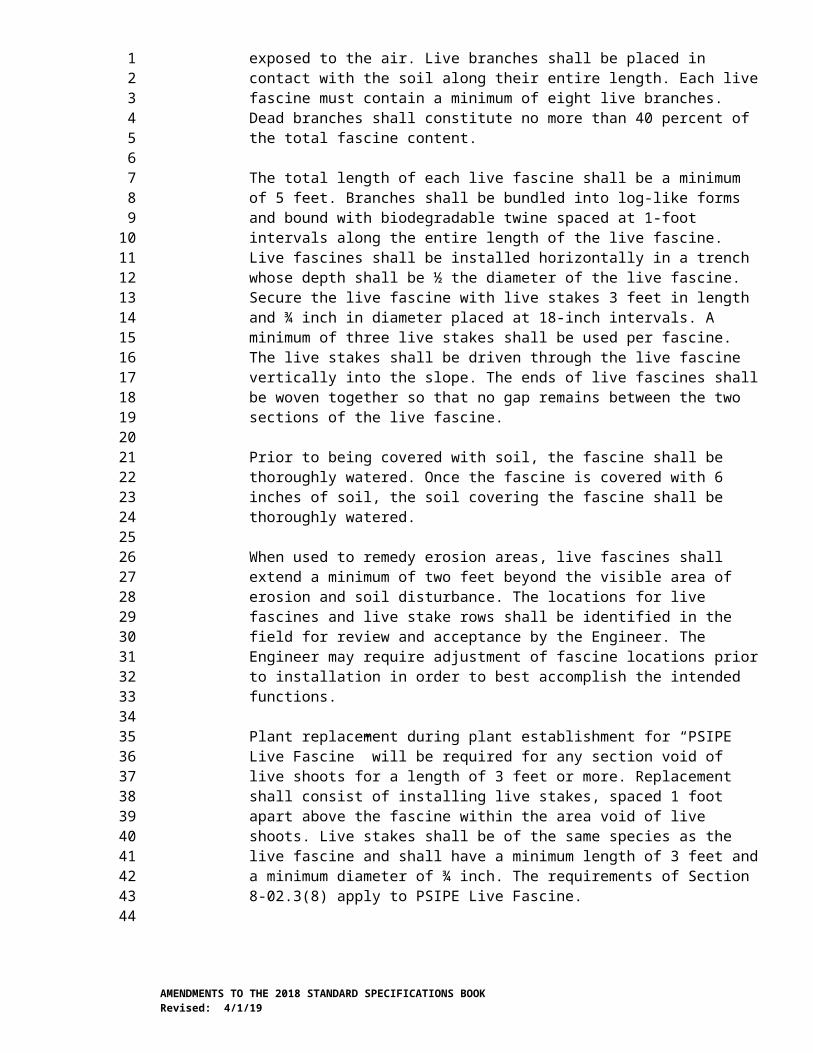
apparatus for 2 hours. After 2 hours, the panel and test apparatus shall be removed and immediately tested to according to ASTM D522 to evaluate cold flexibility. Paint must show no evidence of cracking, chipping or flaking when bent 180 degrees over a mandrel bar of specified diameter.
6NTPEP test deck, or a test deck conforming to ASTM D713, shall be conducted for a minimum of six months with the following additional requirements: it shall be applied at 15 wet mils to a test deck that is located at 40N latitude or higher with at least 10,000 ADT and which was applied during the months of September through November.
7Paint is applied to an approximately 4”x12” aluminum panel using a drawdown bar with a 50 mil gap. The coated panel is allowed to dry under ambient conditions (50±10% RH and 72±5 ˚F) for 24 hours. Visual evaluation of the dry film shall reveal no cracks.
9-34.3 PlasticIn the first sentence of the last paragraph, “Federal Standard 595” is revised to read “SAE AMS Standard 595”.
9-34.3(2) Type B – Pre-Formed Fused ThermoplasticIn the last two paragraphs, each reference to “Federal Standard 595” is revised to read “SAE AMS Standard 595”.
9-34.3(4) Type D – Liquid Cold Applied Methyl MethacrylateThe Test Method value for Adhesion to PCC or HMA, psi is revised to read “ASTM D45411”.
9-34.4 Glass Beads for Pavement Marking MaterialsIn the Test Method column of the table titled Metal Concentration Limits, “EPA 3052 SW-846 6010C” is revised to read “EPA 3052 SW-846 6010D”.
9-34.5(1) Temporary Pavement Marking Tape – Short DurationThis section, including title, is revised to read:
9-34.5(1) Temporary Pavement Marking Tape – Short Duration (Removable)Temporary pavement marking tape for short duration (usage is for up to two months) shall conform to ASTM D4592 Type I except that black tape, black mask tape and the black portion of the contrast removable tape, shall be non-reflective.
9-34.5(2) Temporary Pavement Marking Tape – Long DurationThis section’s title is revised to read:
Temporary Pavement Marking Tape – Long Duration (Non-Removable)
The first sentence is revised to read:
Temporary pavement marking tape for long duration (usage is for greater than two months and less than one year) shall conform to ASTM D4592 Type II.
ASTM E2176 is deleted from the second sentence.
9-34.7(1) RequirementsThe first paragraph is revised to read:
AMENDMENTS TO THE 2018 STANDARD SPECIFICATIONS BOOKRevised: 4/1/19
123456789
10111213141516171819202122232425262728293031323334353637383940414243444546474849505152

Field performance evaluation is required for low VOC solvent-based paint per Section 9-34.2(4), Type A – liquid hot applied thermoplastic per Section 9-34.3(1), Type B – preformed fused thermoplastic per Section 9-34.3(2), Type C – cold applied preformed tape per Section 9-34.3(3), and Type D – liquid applied methyl methacrylate per Section 9-34.3(4).
The last paragraph is deleted.
9-34.7(1)C Auto No-Track TimeThe first paragraph is revised to read:
Auto No-Track Time will only be required for low VOC solvent-based paint in accordance with Section 9-34.2(4).
The second and third sentences of the second paragraph are deleted.
AMENDMENTS TO THE 2018 STANDARD SPECIFICATIONS BOOKRevised: 4/1/19
123456789
10111213141516