Embed Size (px)
Citation preview
UNIT II - E-MAIL SECURITY & FIREWALLSPGP - S/MIME - Internet Firewalls for Trusted System: Roles of Firewalls – Firewall related terminology- Types of Firewalls - Firewall designs - SET for E-Commerce Transactions.
PGPPretty Good Privacy (PGP) was invented by Philip Zimmermann
who released version 1.0 in 1991. Subsequent versions 2.6.x and 5.x (or 3.0) of PGP have been implemented by an all-volunteer collaboration under the design guidance of Zimmermann. PGP is widely used in the individual and commercial versions that run on a variety of platforms throughout the computer community. PGP uses a combination of symmetric secret-key and asymmetric public-key encryption to provide security services for electronic mail and data files. It also provides data integrity services for messages and data files by using digital signature, encryption, compression (zip) and radix-64 conversion (ASCII Armor). With the explosively growing reliance on e-mail and file storage, authentication and confidentiality services have become increasing demands.
In the forthcoming analyses for security and data integrity services, the following symbols are generally used:Ks = session keyKPa = public key of user AKSa = private key of user AE = conventional encryptionEp = public-key encryptionZ = compression using zip algorithm || = concatenation
H = hash functionKPb = public key of user B KSb = private key of user B D = conventional decryption Dp = public-key decryption Z−1 = decompression
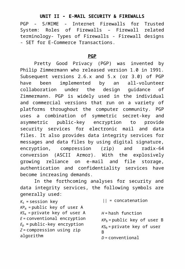
1.1 Confidentiality via EncryptionIn PGP, each symmetric key, known as a session key, is used only once.
A new session key is generated as a random 128-bit number for each message.
Figure illustrates the sequence, which is described as follows:
• The sender creates a message. • The sending PGP generates a random 128-bit number to be used as a
session key for this message only. • The session key is encrypted with RSA, using the recipient’s public key. • The sending PGP encrypts the message, using CAST-128 or IDEA or
3DES, with the session key. Note that the message is also usually compressed. +

• The receiving PGP uses RSA with its private key to decrypt and recover the session key.
• The receiving PGP decrypts the message using the session key. If the message was compressed, it will be decompressed.
Figure: PGP confidentiality computation scheme with compression/decompression Algorithms.
1.2 Authentication via Digital SignatureThe digital signature uses a hash code of the message digest algorithm,
and a public-key signature algorithm. Figure illustrates the digital signature service provided by PGP. The sequence is as follows:
• The sender creates a message. • SHA-1 is used to generate a 160-bit hash code of the message. • The hash code is encrypted with RSA using the sender’s private key and
a digital signature is produced. • The binary signature is attached to the message. • The receiver uses RSA with the sender’s public key to decrypt and
recover the hash code. • The receiver generates a new hash code for the received message and
compares it with the decrypted hash code. If the two match, the message is accepted as authentic.
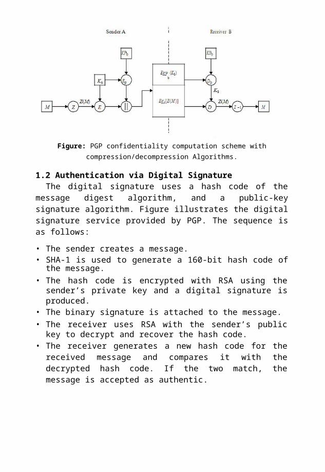
Figure: PGP authentication computation scheme using compression algorithm
1.3 CompressionAs a default, PGP compresses the message after applying the
signature but before encryp-tion. The placement of Z for compression and Z−1 for decompression is shown in Figures 9.1 and 9.2. This compression algorithm has the benefit of saving space both for e-mail transmission and for file storage. However, PGP’s compression technique will present a difficulty. As a default, PGP compresses the message after applying the signature but before encryp-tion. The placement of Z for compression and Z−1 for decompression is shown in Figures 9.1 and 9.2. This compression algorithm has the benefit of saving space both for e-mail transmission and for file storage. However, PGP’s compression technique will present a difficulty.
In 1982 James Storer and Thomas Szymanski presented their scheme, LZSS, based on the work of Lempel and Ziv. In LZSS, the compressor maintains a window of size N bytes and a lookahead buffer. Sliding-window-based schemes can be simplified by numbering the input text characters mod N, in effect creating a circular buffer. Variants of sliding-window schemes can be applied for additional compression to the output of the LZSS compressor, which include a simple variable-length code (LZB), dynamic Huffman coding (LZH) and Shannon – Fano coding (ZIP 1.x). All of them result in a certain degree of improvement over the basic scheme, especially when the data is rather random and the LZSS compressor has little effect.
Recently an algorithm was developed which combines the idea behind LZ77 and LZ78 to produce a hybrid called LZFG. LZFG uses the standard sliding window, but stores the data in a modified tree data structure and produces as output the position of the text in the tree. Since LZFG only inserts complete phrases into the dictionary, it should run faster than other
LZ77-based compressors.
Huffman compression is a statistical data compression technique which reduces the average code length used to represent the symbols of an alphabet. Huffman code is an example of a code which is optimal when all symbols probabilities are integral powers of 1/2. A technique related to Huffman coding is Shannon – Fano coding. This coding divides the set of symbols into two equal or almost equal subsets based on the probability of occurrence of characters in each subset. The first subset is assigned a binary 0, the second a binary 1. Huffman encoding always generates optimal codes, but Shannon – Fano sometimes uses a few more bits.
Decompression of LZ77-compressed text is simple and fast. Whenever a (position, length) pair is encountered, one goes to that position in that window and copies length bytes to the output.
1.4 Radix-64 Conversion When PGP is used, usually part of the block to be transmitted is
encrypted. If only the signature service is used, then the message digest is encrypted (with the sender’s private key). If the confidentiality service is used, the message plus signature (if present) are encrypted (with a one-time symmetric key). Thus, part or all of the resulting block consists of a stream of arbitrary 8-bit octets. However, many electronic mail systems only permit the use of blocks consisting of ASCII text. To accommodate this restriction, PGP provides the service of converting the raw 8-bit binary octets to a stream of printable 7-bit ASCII characters, called radix-64 encoding or ASCII Armor. Therefore, to transport PGP’s raw binary octets through unreliable channels, a printable encoding of these binary octets is needed.
The scheme used for this purpose is radix-64 conversion. Each group of three octets of binary data is mapped into four ASCII characters. This format also appends a CRC to detect transmission errors. This radix-64 conversion is a wrapper around the binary PGP messages, and is used to protect the binary messages during transmission over non-binary channels, such as Internet e-mail.
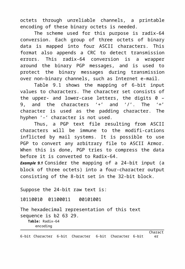
Table 9.1 shows the mapping of 6-bit input values to characters. The character set consists of the upper- and lower-case letters, the digits 0 – 9, and the characters ‘+’ and ‘/’. The ‘=’ character is used as the padding character. The hyphen ‘-’ character is not used.
Thus, a PGP text file resulting from ASCII characters will be immune to the modifi-cations inflicted by mail systems. It is possible to use PGP to convert any arbitrary file to ASCII Armor. When this is done, PGP tries to compress the data before it is converted to Radix-64.Example 9.1 Consider the mapping of a 24-bit input (a block of three octets)
into a four-character output consisting of the 8-bit set in the 32-bit block.
Suppose the 24-bit raw text is:
1011001001100011 00101001
The hexadecimal representation of this text sequence is b2 63 29.
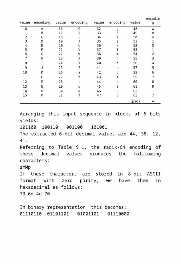
Table: Radix-64 encoding
6-bit Character 6-bit Character 6-bit Character 6-bit Charactervalue encoding value encoding value encoding value encoding
0 A 16 Q 32 g 48 w1 B 17 R 33 h 49 x2 C 18 S 34 i 50 y3 D 19 T 35 j 51 z4 E 20 U 36 k 52 05 F 21 V 37 l 53 16 G 22 W 38 m 54 27 H 23 X 39 n 55 38 I 24 Y 40 o 56 49 J 25 Z 41 p 57 5
10 K 26 a 42 q 58 611 L 27 b 43 r 59 712 M 28 c 44 s 60 813 N 29 d 45 t 61 914 O 30 e 46 u 62 +15 P 31 f 47 v 63 /
(pad) =
Arranging this input sequence in blocks of 6 bits yields:101100 100110 001100 101001The extracted 6-bit decimal values are 44, 38, 12, 41.Referring to Table 9.1, the radix-64 encoding of these decimal values produces the fol-lowing characters:smMpIf these characters are stored in 8-bit ASCII format with zero parity, we have them in hexadecimal as follows:73 6d 4d 70
In binary representation, this becomes:01110110 01101101 01001101 01110000
1.4.1 ASCII Armor Format When PGP encodes data into ASCII Armor, it puts specific headers around the data, so PGP can construct the data later. PGP informs the user about what kind of data is encoded in ASCII Armor through the use of the headers.
Concatenating the following data creates ASCII Armor: an Armor head line, Armor headers, a blank line, ASCII-Armored data, Armor checksum and Armor tail. Specifically, an explanation for each item is as follows:
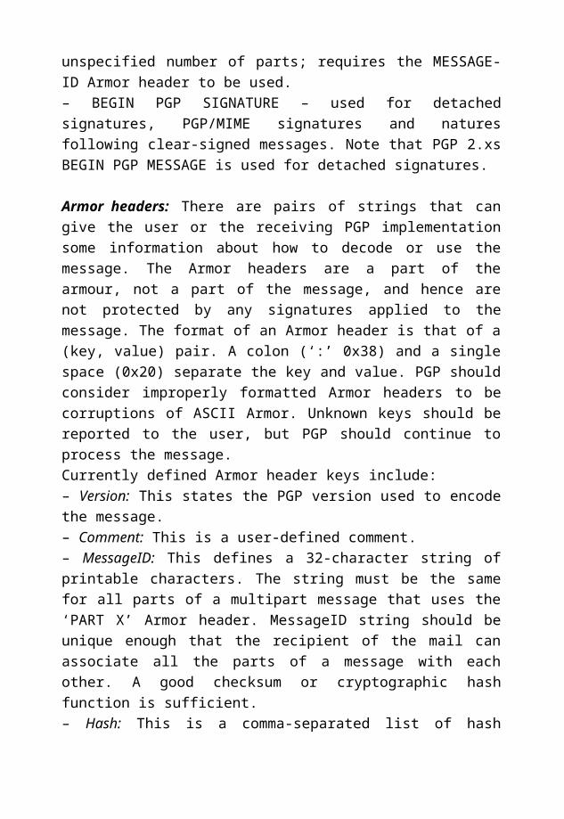
An Armor head line: This consists of the appropriate header line text surrounded by five dashes (‘-’, 0x2D) on either side of the header line text. The header line text is chosen based upon the type of data that is being encoded in Armor, and how it is being encoded. Header line texts include the following strings: – BEGIN PGP MESSAGE – used for signed, encrypted or compressed files. – BEGIN PGP PUBLIC KEY BLOCK – used for armouring public keys. – BEGIN PGP PRIVATE KEY BLOCK – used for armouring private keys. – BEGIN PGP MESSAGE, PART X/Y – used for multipart messages, where the armour is divided amongst Y parts, and this is the Xth part out of Y. – BEGIN PGP MESSAGE, PART X – used for multipart messages, where this is the Xth part of an unspecified number of parts; requires the MESSAGE-ID Armor header to be used. – BEGIN PGP SIGNATURE – used for detached signatures, PGP/MIME signatures and natures following clear-signed messages. Note that PGP 2.xs BEGIN PGP MESSAGE is used for detached signatures.
Armor headers: There are pairs of strings that can give the user or the receiving PGP implementation some information about how to decode or use the message. The Armor headers are a part of the armour, not a part of the message, and hence are not protected by any signatures applied to the message. The format of an Armor header is that of a (key, value) pair. A colon (‘:’ 0x38) and a single space (0x20) separate the key and value. PGP should consider improperly formatted Armor headers to be corruptions of ASCII Armor. Unknown keys should be reported to the user, but PGP should continue to process the message. Currently defined Armor header keys include: – Version: This states the PGP version used to encode the message. – Comment: This is a user-defined comment.
– MessageID: This defines a 32-character string of printable characters. The string must be the same for all parts of a multipart message that uses the ‘PART X’ Armor header. MessageID string should be unique enough that the recipient of the mail can associate all the parts of a message with each other. A good checksum or cryptographic hash function is sufficient. – Hash: This is a comma-separated list of hash algorithms used in the message. This is used only in clear-signed messages. – Charset: This is a description of the character set that the plaintext is in. PGP defines text to be in UTF-8 by default. An implementation will get the best results by translating into and out of UTF-8 (see RFC 2279). However, there are many instance where this is easier said than done. Also, there are communities of users who have no need for UTF-8 because they are all satisfied with a character set like ISO Latin-5 or a Japanese one. In such instances, an implementation may override the UTF-8 default by using this header key.
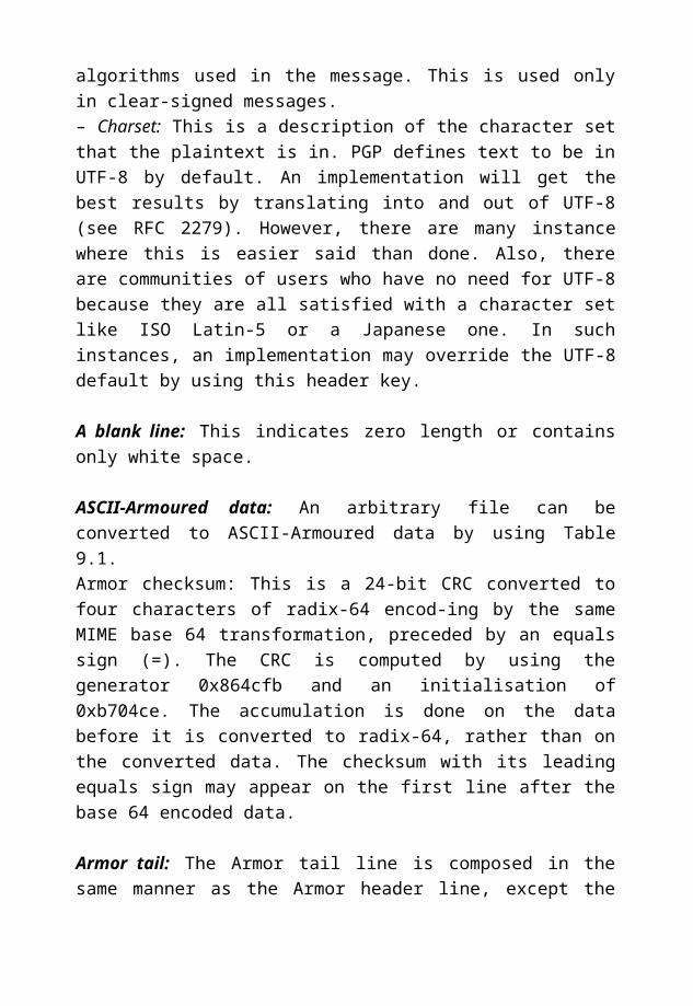
A blank line: This indicates zero length or contains only white space.
ASCII-Armoured data: An arbitrary file can be converted to ASCII-Armoured data by using Table 9.1. Armor checksum: This is a 24-bit CRC converted to four characters of radix-64 encod-ing by the same MIME base 64 transformation, preceded by an equals sign (=). The CRC is computed by using the generator 0x864cfb and an initialisation of 0xb704ce. The accumulation is done on the data before it is converted to radix-64, rather than on the converted data. The checksum with its leading equals sign may appear on the first line after the base 64 encoded data.
Armor tail: The Armor tail line is composed in the same manner as the Armor header line, except the string ‘BEGIN’ is replaced by the string ‘END’.
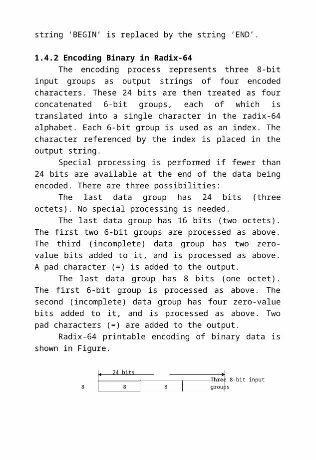
1.4.2 Encoding Binary in Radix-64 The encoding process represents three 8-bit input groups as output
strings of four encoded characters. These 24 bits are then treated as four concatenated 6-bit groups, each of which is translated into a single character in the radix-64 alphabet. Each 6-bit group is used as an index. The character referenced by the index is placed in the output string.
Special processing is performed if fewer than 24 bits are available at
the end of the data being encoded. There are three possibilities:The last data group has 24 bits (three octets). No special processing is
needed. The last data group has 16 bits (two octets). The first two 6-bit
groups are processed as above. The third (incomplete) data group has two zero-value bits added to it, and is processed as above. A pad character (=) is added to the output.
The last data group has 8 bits (one octet). The first 6-bit group is processed as above. The second (incomplete) data group has four zero-value bits added to it, and is processed as above. Two pad characters (=) are added to the output.
Radix-64 printable encoding of binary data is shown in Figure.
24 bits
8 8 8 Three 8-bit input groups
6 6 6 6 Four concatenated 6-bit groupsused as indexes
R-64 R-64 R-64 R-64 Radix-64 encoding
8 8 8 8 Four characters (32 bits)stored in 8-bit ASCII format
Four characters (32 bits)
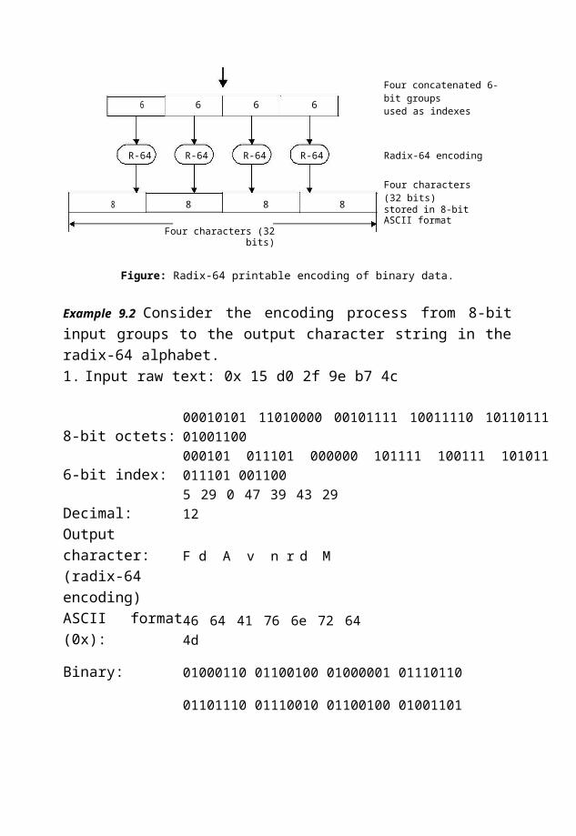
Figure: Radix-64 printable encoding of binary data.
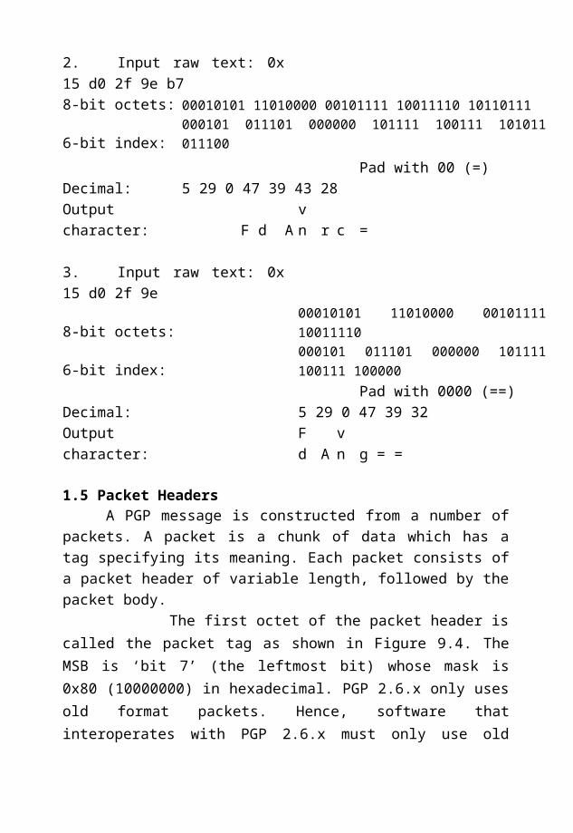
Example 9.2 Consider the encoding process from 8-bit input groups to the output character string in the radix-64 alphabet.1. Input raw text: 0x 15 d0 2f 9e b7 4c
8-bit octets: 00010101 11010000 00101111 10011110 10110111 010011006-bit index: 000101 011101 000000 101111 100111 101011 011101 001100Decimal: 5 29 0 47 39 43 29 12Output character: F d A v n r d M(radix-64 encoding)ASCII format (0x): 46 64 41 76 6e 72 64 4d
Binary: 01000110 01100100 01000001 01110110
01101110 01110010 01100100 01001101
2. Input raw text: 0x 15 d0 2f 9e b78-bit octets: 00010101 11010000 00101111 10011110 101101116-bit index: 000101 011101 000000 101111 100111 101011 011100
Decimal: 5 29 0 47 39 43 28Pad with 00 (=)
Output character: F d A v nr c =
3. Input raw text: 0x 15 d0 2f 9e8-bit octets: 00010101 11010000 00101111 10011110
6-bit index:000101 011101 000000 101111 100111 100000
Pad with 0000 (==)Decimal: 5 29 0 47 39 32
Output character: F d A v ng = =
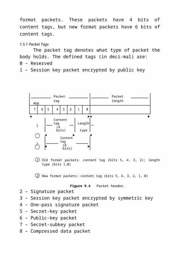
1.5 Packet HeadersA PGP message is constructed from a number of packets. A packet is
a chunk of data which has a tag specifying its meaning. Each packet consists of a packet header of variable length, followed by the packet body. The first octet of the packet header is called the packet tag as shown in Figure 9.4. The MSB is ‘bit 7’ (the leftmost bit) whose mask is 0x80 (10000000) in hexadecimal. PGP 2.6.x only uses old format packets. Hence, software that interoperates with PGP 2.6.x must only use old format packets. These packets have 4 bits of content tags, but new format packets have 6 bits of content tags.
1.5.1 Packet Tags The packet tag denotes what type of packet the body holds. The
defined tags (in deci-mal) are:0 – Reserved1 – Session key packet encrypted by public key
Packet tag Packet lengthMSB
7 6 5 4 3 2 1 0
1Content tag Length
(4 bits) type
2Content tag
(6 bits)
1 Old format packets: content tag (bits 5, 4, 3, 2); length type (bits 1,0)
2 New format packets: content tag (bits 5, 4, 3, 2, 1, 0)
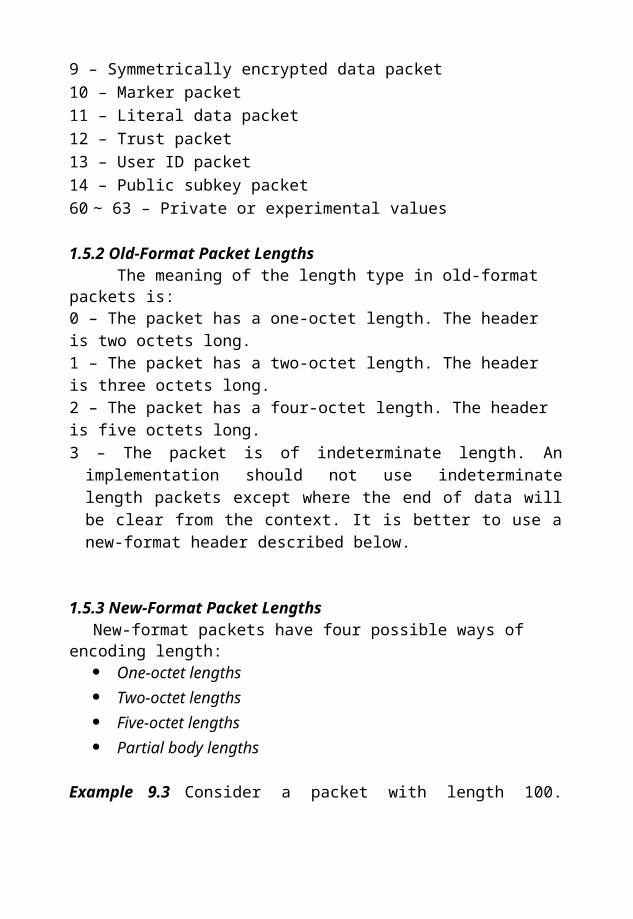
Figure 9.4 Packet header.2 – Signature packet3 – Session key packet encrypted by symmetric key4 – One-pass signature packet5 – Secret-key packet6 – Public-key packet7 – Secret-subkey packet8 – Compressed data packet9 – Symmetrically encrypted data packet10 – Marker packet11 – Literal data packet12 – Trust packet13 – User ID packet14 – Public subkey packet60 ∼ 63 – Private or experimental values
1.5.2 Old-Format Packet Lengths The meaning of the length type in old-format packets is:
0 – The packet has a one-octet length. The header is two octets long. 1 – The packet has a two-octet length. The header is three octets long. 2 – The packet has a four-octet length. The header is five octets long.3 – The packet is of indeterminate length. An implementation should not use
indeterminate length packets except where the end of data will be clear from the context. It is better to use a new-format header described below.
1.5.3 New-Format Packet Lengths
New-format packets have four possible ways of encoding length: One-octet lengths Two-octet lengths Five-octet lengths Partial body lengths
Example 9.3 Consider a packet with length 100. Compute its length encoded in one octet. Now:
100 (decimal) = 26 + 25 + 22 = 01100100(binary) = 0x64 (hex)Thus, a packet with length 100 may have its length encoded in one octet: 0x64. This header is followed by 100 octets of data. Similarly, a packet with length 1723 may have its length encoded in two octets: 0xc5, 0xfb. This header is followed by the 1723 octets of data. A packet with length 100000 may have its length encoded in five octets: 0xff, 0x00, 0x01, 0x86, 0xa0.
PGP Packet StructureA PGP file consists of a message packet, a signature packet and a
session key packet.
1.Message Packet This packet includes the actual data to be transmitted or stored as well as a header that includes control information generated by PGP such as a filename and a timestamp. A timestamp specifies the time of creation. The message component consists of a single literal data packet.
2.Signature Packet (Tag 2) This packet describes a binding between some public key and some data. The most common signatures are a signature of a file or a block of text, and a signature that is a certification of a user ID.
The signature includes the following components:
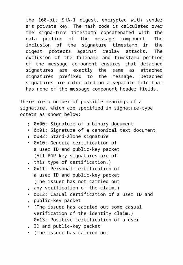
• Timestamp: This is the time at which the signature was created. • Message digest (or hash code): A hash code represents the 160-bit SHA-
1 digest, encrypted with sender a’s private key. The hash code is calculated over the signa-ture timestamp concatenated with the data portion of the message component. The inclusion of the signature timestamp in the digest protects against replay attacks. The exclusion of the filename and timestamp portion of the message component ensures that detached signatures are exactly the same as attached signatures prefixed to the message. Detached signatures are calculated on a separate
file that has none of the message component header fields.
There are a number of possible meanings of a signature, which are specified in signature-type octets as shown below:
• 0x00: Signature of a binary document•• 0x01: Signature of a canonical text document• 0x02: Stand-alone signature•• 0x10: Generic certification of a user ID and
public-key packet (All PGP key signatures are of this type of certification.)•
• 0x11: Personal certification of a user ID and public-key packet (The issuer has not carried out any verification of the claim.)•
• 0x12: Casual certification of a user ID and public-key packet•• (The issuer has carried out some casual verification of the
identity claim.) 0x13: Positive certification of a user ID and public-key packet•
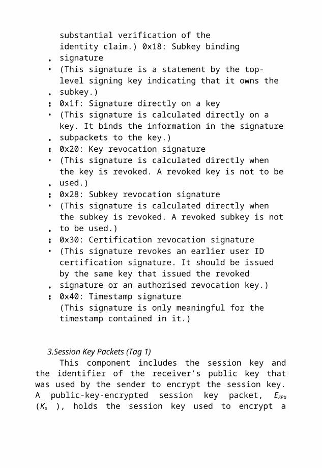
• (The issuer has carried out substantial verification of the identity claim.) 0x18: Subkey binding signature•
• (This signature is a statement by the top-level signing key indicating that it owns the subkey.)•
• 0x1f: Signature directly on a key•• (This signature is calculated directly on a key. It binds the
information in the signature subpackets to the key.)•• 0x20: Key revocation signature•• (This signature is calculated directly when the key is revoked. A
revoked key is not to be used.)•• 0x28: Subkey revocation signature•• (This signature is calculated directly when the subkey is revoked. A
revoked subkey is not to be used.)•• 0x30: Certification revocation signature•• (This signature revokes an earlier user ID certification signature. It
should be issued by the same key that issued the revoked signature or an authorised revocation key.)•
• 0x40: Timestamp signature•(This signature is only meaningful for the timestamp contained in it.)
3.Session Key Packets (Tag 1) This component includes the session key and the identifier of the
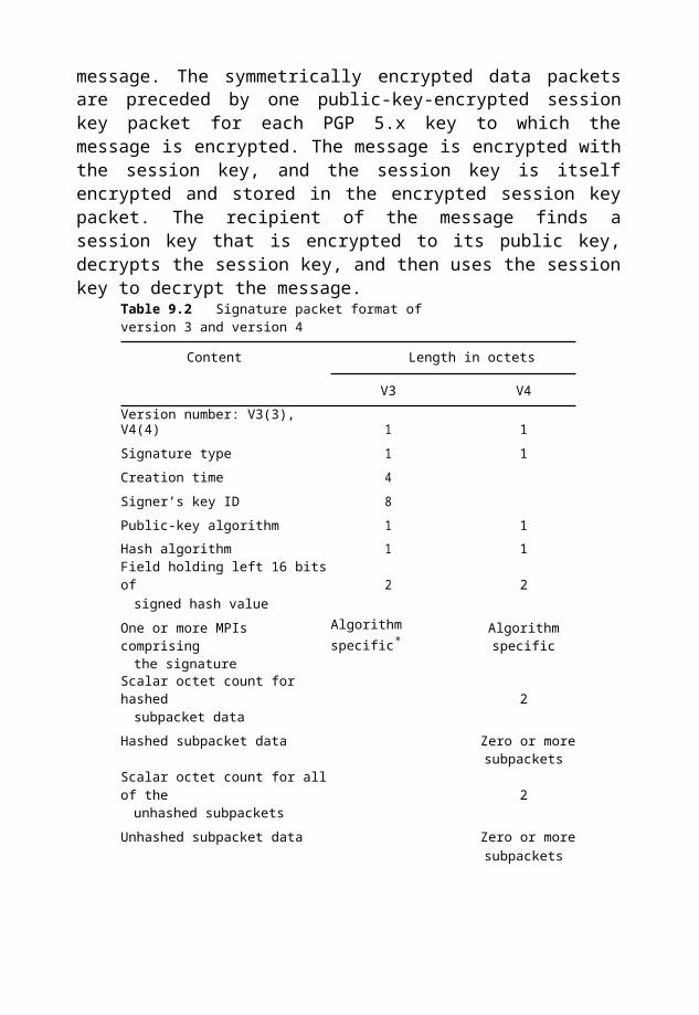
receiver’s public key that was used by the sender to encrypt the session key. A public-key-encrypted session key packet, EKPb (Ks ), holds the session key used to encrypt a message. The symmetrically encrypted data packets are preceded by one public-key-encrypted session key packet for each PGP 5.x key to which the message is encrypted. The message is encrypted with the session key, and the session key is itself encrypted and stored in the encrypted session key packet. The recipient of the message finds a session key that is encrypted to its public key, decrypts the session key, and then uses the session key to decrypt the message.
Table 9.2 Signature packet format of version 3 and version 4
Content Length in octets
V3 V4
Version number: V3(3), V4(4) 1 1Signature type 1 1Creation time 4Signer’s key ID 8Public-key algorithm 1 1Hash algorithm 1 1Field holding left 16 bits of 2 2
signed hash value
One or more MPIs comprising Algorithm specific∗ Algorithm specificthe signature
Scalar octet count for hashed 2subpacket data
Hashed subpacket data Zero or moresubpackets
Scalar octet count for all of the 2unhashed subpackets
Unhashed subpacket data Zero or moresubpackets
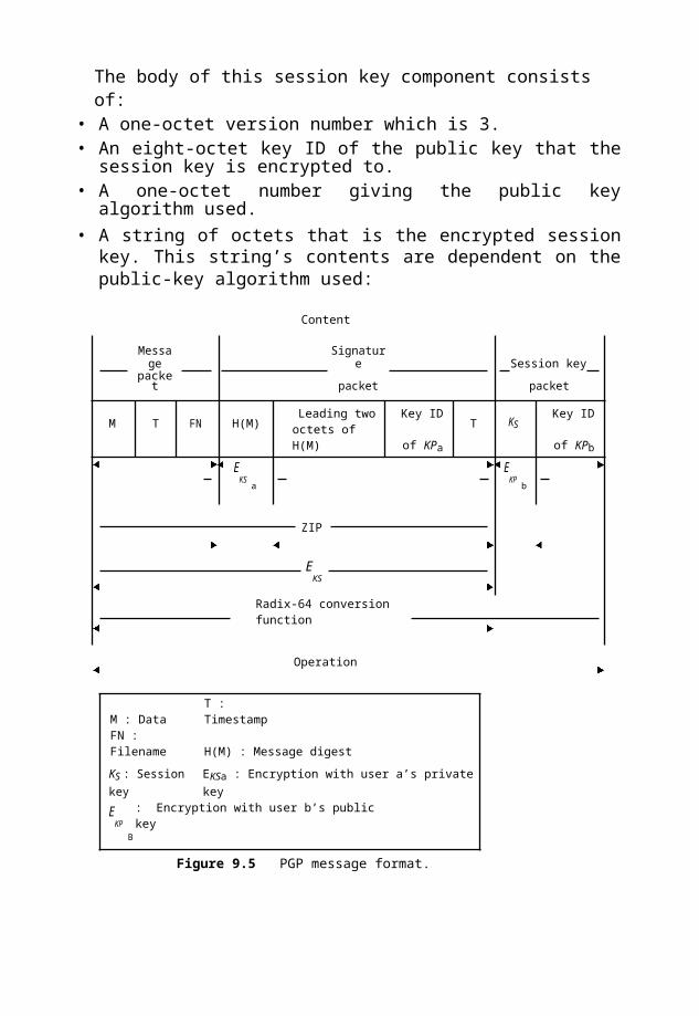
The body of this session key component consists of:• A one-octet version number which is 3. • An eight-octet key ID of the public key that the session key is encrypted
to. • A one-octet number giving the public key algorithm used. • A string of octets that is the encrypted session key. This string’s contents
are dependent on the public-key algorithm used:
Content
Message Signature Session keypacket packet packet
M T FN H(M)Leading two Key ID
T KSKey ID
octets of H(M) of KPa of KPb
EKS a
EKP b
ZIP
EKS
Radix-64 conversion function
Operation
M : Data T : Timestamp
FN : Filename H(M) : Message digest
KS : Session key EKSa : Encryption with user a’s private keyE
KP : Encryption with user b’s public keyB
Figure 9.5 PGP message format.
9.1.7 Key Material Packet
9.1.7.1 Key Packet Variants There are:• Public-key packet (tag 6): This packet starts a series of packets that forms
a PGP 5.x key.• Public subkey packet (tag 14): This packet has exactly the same format as
a public-key packet, but denotes a subkey. One or more subkeys may be associated with a top-level key. The top-level key provides signature services, and the subkeys provide encryption services. PGP 2.6.x ignores public-subkey packets.
• Secret-key packet (tag 5): This packet contains all the information that is found in a public-key packet, including the public-key materials, but also includes the secret-key material after all the public-key fields.
• Secret-subkey packet (tag 7): A secret-subkey packet is the subkey analogous to the secret-key packet and has exactly the same format.
9.1.7.2 Public-key Packet Formats
There are two variants of version 3 packets and version 2 packets. Version 3 packets were originally generated by PGP 2.6. Version 2 packets are identical in format to version 3 packets, but are generated by PGP 2.5. However, v2 keys are deprecated and they must not be generated. PGP 5.0 introduced version 4 packets, with new fields and semantics. PGP 2.6.x will not accept key-material packets with versions greater than 3. PGP 5.x (or PGP3) implementation should create keys with version 4 format, but v4 keys correct some security deficiencies in v3 keys.
A v3 key packet contains:• A one-octet version number (3). • A four-octet number denoting the time that the key was created. • A two-octet number denoting the time in days that this key is valid. • A one-octet number denoting the public-key algorithm of this key. • A series of multiprecision integers (MPIs) comprising the key material:
an MPI of RSA public module n; an MPI of RSA public encryption exponent e.
A key ID is an eight-octet scalar that identifies a key. For a v3 key, the eight-octet key ID consists of the low 64 bits of the public modulus of the RSA key. The fingerprint of a v3 key is formed by hashing the body (excluding the two-octet length) of the MPIs that form the key material with MD5.
Note that MPIs are unsigned integers. An MPI consists of two parts: a two-octet scalar that is the length of the MPI in bits followed by a string of octets that contain the actual integer.
Example 9.4 Suppose the string of octets [0009 01ff] forms an MPI. The length of the MPI in bits is [00000000 00001001] or 9 (= 23 + 20) in octets. The actual integer value of the MPI is:
[01ff] = 28 + 27 + 26 + 25 + 24 + 23 + 22 + 21 + 20 = 511
The MPI size is:((MPI.length + 7)/8) + 2 = ((9 + 7)/8) + 2 = 4 octetswhich checks the given size of the MPI string.
The v4 format is similar to the v3 format except for the absence of a validity period. Fingerprints of v4 keys are calculated differently from v3 keys. A v4 fingerprint is the 160-bit SHA-1 hash of the one-octet packet tag, followed by the two-octet packet length, followed by the entire public-key packet starting with the version field. The key ID is the low-order 64 bits of the fingerprint.
A v4 key packet contains:• A one-octet version number (4). • A four-octet number denoting the time that the key was created. • A one-octet number denoting the public-key algorithm of this key. • A series of MPIs comprising the key material:
– Algorithm-specific fields for RSA public keys: MPI of RSA public modulus n; MPI of RSA public encryption exponent e.
– Algorithm-specific fields for DSA public keys: MPI of DSA prime p; MPI of DSA group order q (q is a prime divisor of p − 1); MPI of DSA group generator g; MPI of DSA public key value y = gx where x is secret.
– Algorithm-specific fields for ElGamal public keys: MPI of ElGamal prime p; MPI of ElGamal group generator g; MPI of ElGamal public key value y = gx where x is secret.
9.1.7.3 Secret-key Packet Formats The secret-key and secret-subkey packets contain all the data of
public-key and public-subkey packets in encrypted form, with additional algorithm-specific key data appended.
The secret-key packet contains:• A public-key or public-subkey packet, as described above. • One octet indicating string-to-key (S2K) usage conventions: 0 indicates
that the secret-key data is not encrypted; 255 indicates that an S2K specifier is being given. Any other value specifies a symmetric-key encryption algorithm.
• If the S2K usage octet was 255, a one-octet symmetric encryption algorithm (optional).
• If the S2K usage octet was 255, an S2K specifier (optional). The length of the S2K specifier is implied by its type, as described above.
• If secret data is encrypted, an eight-octet IV (optional). • Encrypted MPIs comprising the secret-key data. These algorithm-specific
fields are as described below. • A two-octet checksum of the plaintext of the algorithm-specific portion
(sum of all octets, mod 216 = mod 65 536): – Algorithm-specific fields for RSA secret keys: MPI of RSA secret
exponent d; MPI of RSA secret prime value p; MPI of RSA secret prime value q (p < q); MPI of u, the multiplicative inverse of p, mod q.
– Algorithm-specific fields for DSA secret keys: MPI of DSA secret exponent x.
– Algorithm-specific fields for ElGamal secret keys: MPI of ElGamal secret expo-nent x.
Simple S2K directly hashes the string to produce the key data:
Octet 0: 0x00Octet 1: hash algorithm
It also hashes the passphrase to produce the session key. The hashing process to be done depends on the size of the session key and the size of the hash algorithm’s output. If the hash size is greater than or equal to the session key size, the higher-order (leftmost) octets of the hash are used as the key. If the hash size is less than the key size, multiple instances are preloaded with 0, 1, 2, . . . octets of zeros in order to produce the required key data.
S2K specifiers are used to convert passphrase strings into symmetric-key encryp-tion/decryption keys. They are currently used in two ways: to encrypt the secret part of private keys in the private keyring, and to convert passphrases to encryption keys for symmetrically encrypted messages.
Secret MPI values can be encrypted using a passphrase. If an S2K specifier is given, it describes the algorithm for converting the passphrase to a key, otherwise a simple MD5 hash of the passphrase is used. The cipher for encrypting the MPIs is specified in the secret-key packet.
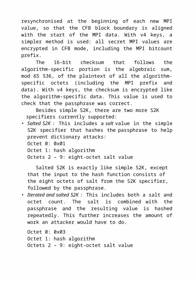
Encryption/decryption of the secret data is done in CFB (Cipher Feedback) mode using the key created from the passphrase and IV from the packet. A different mode is used with v3 keys (which are only RSA) than with other key formats. With v3 keys, the prefix data (the first two octets) of the MPI is not encrypted; only the MPI non-prefix data is encrypted. Furthermore, the CFB state is resynchronised at the beginning of each new MPI value, so that the CFB block boundary is aligned with the start of the MPI data. With v4 keys, a simpler method is used: all secret MPI values are encrypted in CFB mode, including the MPI bitcount prefix.
The 16-bit checksum that follows the algorithm-specific portion is the algebraic sum, mod 65 536, of the plaintext of all the algorithm-specific octets (including the MPI prefix and data). With v4 keys, the checksum is encrypted like the algorithm-specific data. This value is used to check that the passphrase was correct.
Besides simple S2K, there are two more S2K specifiers currently supported:
• Salted S2K : This includes a salt value in the simple S2K specifier that hashes the passphrase to help prevent dictionary attacks: Octet 0: 0x01
Octet 1: hash algorithm Octets 2 – 9: eight-octet salt value
Salted S2K is exactly like simple S2K, except that the input to the hash function consists of the eight octets of salt from the S2K specifier, followed by the passphrase.
• Iterated and salted S2K : This includes both a salt and octet count. The salt is combined with the passphrase and the resulting value is hashed repeatedly. This further increases the amount of work an attacker would have to do.
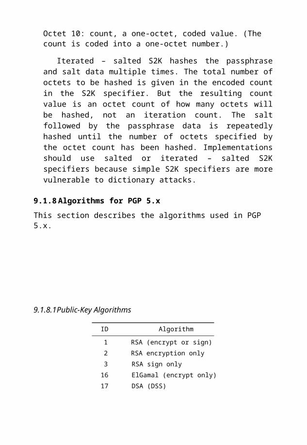
Octet 0: 0x03 Octet 1: hash algorithm Octets 2 – 9: eight-octet salt valueOctet 10: count, a one-octet, coded value. (The count is coded into a one-octet number.)
Iterated – salted S2K hashes the passphrase and salt data multiple times. The total number of octets to be hashed is given in the encoded count in the S2K specifier. But the resulting count value is an octet count of how many octets will be hashed, not an iteration count. The salt followed by the passphrase data is repeatedly hashed until the number of octets specified by the octet count has been hashed. Implementations should use salted or iterated – salted S2K specifiers because simple S2K specifiers are more vulnerable to dictionary attacks.
9.1.8 Algorithms for PGP 5.x
This section describes the algorithms used in PGP 5.x.
9.1.8.1 Public-Key Algorithms
ID Algorithm
1 RSA (encrypt or sign)2 RSA encryption only3 RSA sign only
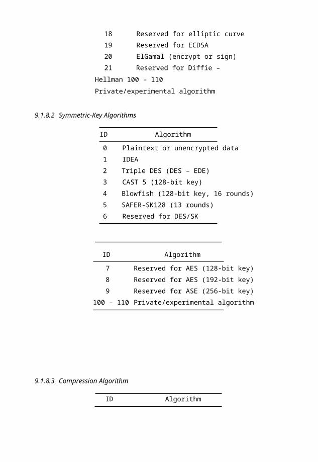
16 ElGamal (encrypt only) 17 DSA (DSS) 18 Reserved for elliptic curve 19 Reserved for ECDSA 20 ElGamal (encrypt or sign) 21 Reserved for Diffie – Hellman
100 – 110 Private/experimental algorithm
9.1.8.2 Symmetric-Key Algorithms
ID Algorithm
0 Plaintext or unencrypted data 1 IDEA 2 Triple DES (DES – EDE)3 CAST 5 (128-bit key) 4 Blowfish (128-bit key, 16 rounds)5 SAFER-SK128 (13 rounds)6 Reserved for DES/SK
ID Algorithm
7 Reserved for AES (128-bit key)8 Reserved for AES (192-bit key)9 Reserved for ASE (256-bit key)
100 – 110 Private/experimental algorithm
9.1.8.3 Compression Algorithm
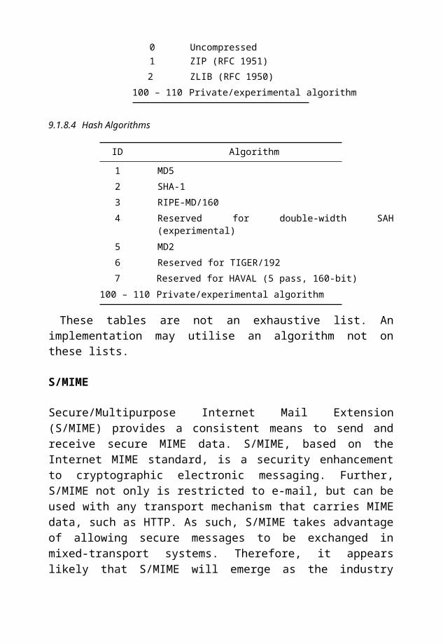
ID Algorithm
0 Uncompressed1 ZIP (RFC 1951)2 ZLIB (RFC 1950)
100 – 110 Private/experimental algorithm
9.1.8.4 Hash Algorithms
ID Algorithm
1 MD5 2 SHA-1 3 RIPE-MD/160 4 Reserved for double-width SAH (experimental) 5 MD2 6 Reserved for TIGER/192 7 Reserved for HAVAL (5 pass, 160-bit)
100 – 110 Private/experimental algorithm
These tables are not an exhaustive list. An implementation may utilise an algorithm not on these lists.
S/MIME
Secure/Multipurpose Internet Mail Extension (S/MIME) provides a consistent means to send and receive secure MIME data. S/MIME, based on the Internet MIME standard, is a security enhancement to cryptographic electronic messaging. Further, S/MIME not only is restricted to e-mail, but can be used with any transport mechanism that carries MIME data, such as HTTP. As such, S/MIME takes advantage of allowing secure messages to be exchanged in mixed-transport systems. Therefore, it appears likely that S/MIME will emerge as the industry standard for commercial and organisational use. This section describes a protocol for adding digital signature and encryption services to MIME data.
9.2.1 MIME SMTP is a simple mail transfer protocol by which messages are sent only in NVT (Net-work Virtual Terminal) 7-bit ASCII format. NVT normally uses what is called NVT ASCII. This is an 8-bit character set in which the seven lowest-order bits are the same as ASCII and the highest-order bit is zero.
MIME was defined to allow transmission of non-ASCII data through e-mail. MIME allows arbitrary data to be encoded in ASCII and then transmitted in a standard e-mail mes-sage. It is a supplementary protocol that allows non-ASCII data to be sent through SMTP. However, MIME is not a
mail protocol and cannot replace SMTP; it is only an extension to SMTP. In fact, MIME does not change SMTP or POP3, neither does it replace them.
The MIME standard provides a general structure for the content type of Internet mes-sages and allows extensions for new content-type applications. To accommodate arbitrary data types and representations, each MIME message includes information that tells the recipient the type of the data and the encoding used. The MIME standard specifies that a content-type declaration must contain two identifiers, a content type and a subtype, separated by a slash.
9.2.1.1 MIME Description
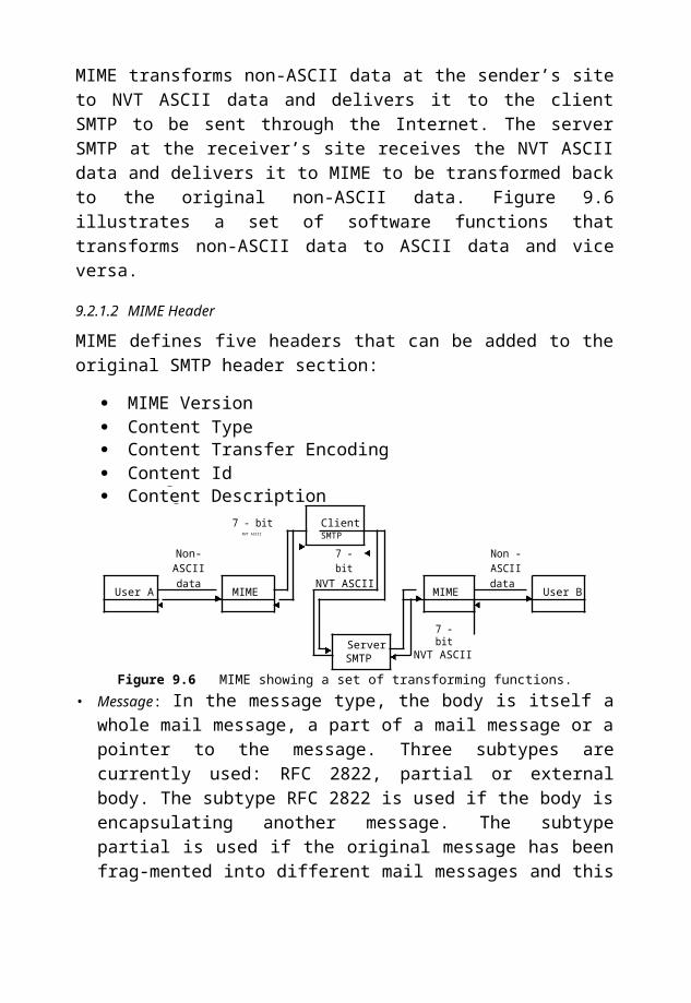
MIME transforms non-ASCII data at the sender’s site to NVT ASCII data and delivers it to the client SMTP to be sent through the Internet. The server SMTP at the receiver’s site receives the NVT ASCII data and delivers it to MIME to be transformed back to the original non-ASCII data. Figure 9.6 illustrates a set of software functions that transforms non-ASCII data to ASCII data and vice versa.
9.2.1.2 MIME Header
MIME defines five headers that can be added to the original SMTP header section:
MIME Version Content Type Content Transfer Encoding Content Id Content Description
7 - bit ClientNVT ASCII SMTP
Non-ASCII 7 - bit Non - ASCII
User Adata
MIMENVT ASCII
MIMEdata
User B
7 - bitServerNVT ASCIISMTP
Figure 9.6 MIME showing a set of transforming functions.• Message: In the message type, the body is itself a whole mail message, a
part of a mail message or a pointer to the message. Three subtypes are currently used: RFC 2822, partial or external body. The subtype RFC 2822 is used if the body is encapsulating another message. The subtype partial is used if the original message has been frag-mented into different mail messages and this mail message is one of the fragments. The

fragments must be reassembled at the destination by MIME. Three parameters must be added: ID, number and total. The id identifies the message and is present in all the fragments. The number defines the sequence order of the fragment. The total defines the number of fragments that comprise the original message.
• Image: The original message is a stationary image, indicating that there is no anima-tion. The two subtypes currently used are Joint Photographic Experts Group (JPEG), which uses image compression, and Graphics Interchange Format (GIF).
• Video: The original message is a time-varying image (animation). The only subtype is Motion Picture Experts Group (MPEG). If the animated image contains sound, it must be sent separately using the audio content type.
• Audio: The original message contains sound. The only subtype is basic, which uses 8 kHz standard audio data.
• Application: The original message is a type of data not previously defined. There are only two subtypes used currently: octet-stream and PostScript. Octet-stream is used when the data represents a sequence of binary data consisting of 8-bit bytes. PostScript is used when the data is in Adobe PostScript format for printers that support PostScript.
Content Transfer Encoding
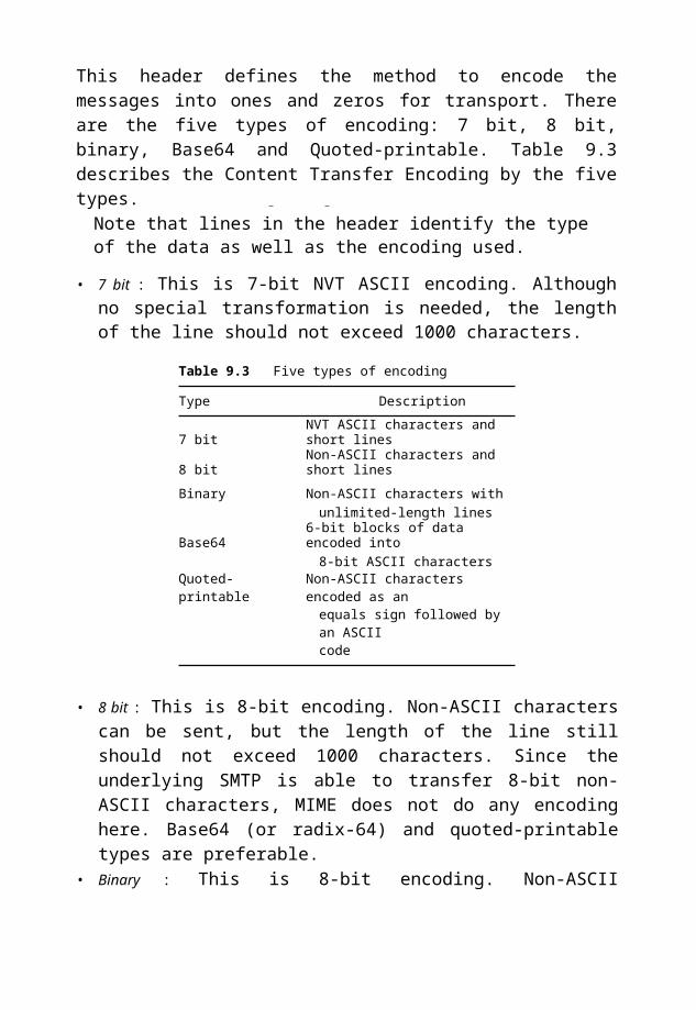
This header defines the method to encode the messages into ones and zeros for transport. There are the five types of encoding: 7 bit, 8 bit, binary, Base64 and Quoted-printable. Table 9.3 describes the Content Transfer Encoding by the five types.
Note that lines in the header identify the type of the data as well as the encoding used.
• 7 bit : This is 7-bit NVT ASCII encoding. Although no special transformation is needed, the length of the line should not exceed 1000 characters.
Table 9.3 Five types of encoding
Type Description
7 bit NVT ASCII characters and short lines8 bit Non-ASCII characters and short linesBinary Non-ASCII characters with
unlimited-length lines
Base64 6-bit blocks of data encoded into8-bit ASCII characters
Quoted-printable Non-ASCII characters encoded as anequals sign followed by an ASCIIcode
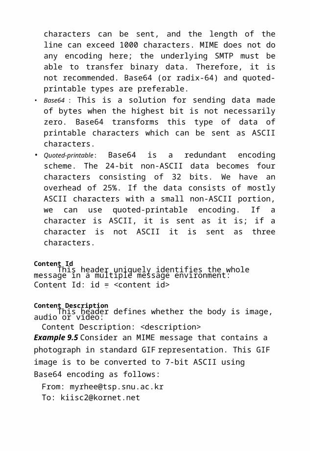
• 8 bit : This is 8-bit encoding. Non-ASCII characters can be sent, but the length of the line still should not exceed 1000 characters. Since the underlying SMTP is able to transfer 8-bit non-ASCII characters, MIME does not do any encoding here. Base64 (or radix-64) and quoted-printable types are preferable.
• Binary : This is 8-bit encoding. Non-ASCII characters can be sent, and the length of the line can exceed 1000 characters. MIME does not do any encoding here; the underlying SMTP must be able to transfer binary data. Therefore, it is not recommended. Base64 (or radix-64) and quoted-printable types are preferable.
• Base64 : This is a solution for sending data made of bytes when the highest bit is not necessarily zero. Base64 transforms this type of data of printable characters which can be sent as ASCII characters.
• Quoted-printable: Base64 is a redundant encoding scheme. The 24-bit non-ASCII data becomes four characters consisting of 32 bits. We have an overhead of 25%. If the data consists of mostly ASCII characters with a small non-ASCII portion, we can use quoted-printable encoding. If a character is ASCII, it is sent as it is; if a character is not ASCII it is sent as three characters.
Content IdThis header uniquely identifies the whole message in a multiple
message environment:Content Id: id = <content id>
Content DescriptionThis header defines whether the body is image, audio or video:
Content Description: <description>Example 9.5 Consider an MIME message that contains a photograph in standard GIF representation. This GIF image is to be converted to 7-bit ASCII using Base64 encoding as follows:
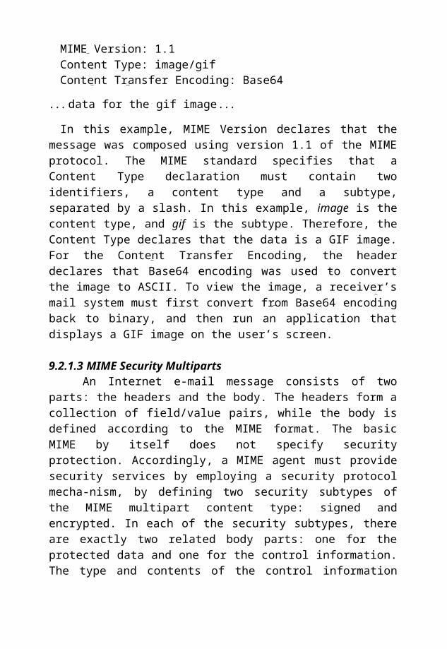
From: [email protected]: [email protected] Version: 1.1Content Type: image/gif
Content Transfer Encoding: Base64
. . . data for the gif image . . .
In this example, MIME Version declares that the message was composed using version 1.1 of the MIME protocol. The MIME standard specifies that a Content Type declaration must contain two identifiers, a content type and a subtype, separated by a slash. In this example, image is the content type, and gif is the subtype. Therefore, the Content Type declares that the data is a GIF image. For the Content Transfer Encoding, the header declares that Base64 encoding was used to convert the image to ASCII. To view the image, a receiver’s mail system must first convert from Base64 encoding back to binary, and then run an application that displays a GIF image on the user’s screen.
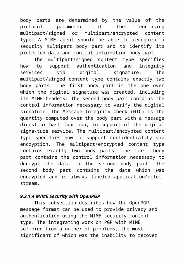
9.2.1.3 MIME Security Multiparts An Internet e-mail message consists of two parts: the headers and the
body. The headers form a collection of field/value pairs, while the body is defined according to the MIME format. The basic MIME by itself does not specify security protection. Accordingly, a MIME agent must provide security services by employing a security protocol mecha-nism, by defining two security subtypes of the MIME multipart content type: signed and encrypted. In each of the security subtypes, there are exactly two related body parts: one for the protected data and one for the control information. The type and contents of the control information body parts are determined by the value of the protocol parameter of the enclosing multipart/signed or multipart/encrypted content type. A MIME agent should be able to recognise a security multipart body part and to identify its protected data and control information body part.
The multipart/signed content type specifies how to support authentication and integrity services via digital signature. The multipart/singed content type contains exactly two body parts. The first body part is the one over which the digital signature was created, including its MIME headers. The second body part contains the control information necessary to verify the digital signature. The Message Integrity Check (MIC) is the quantity computed over the body part with a message digest or hash function, in support of the digital signa-ture service. The multipart/encrypted content type specifies how to support confidentiality via encryption. The multipart/encrypted content type contains exactly two body parts. The first body part contains the control information necessary to decrypt the data in the second body part. The second body part contains the data which was
encrypted and is always labeled application/octet-stream.
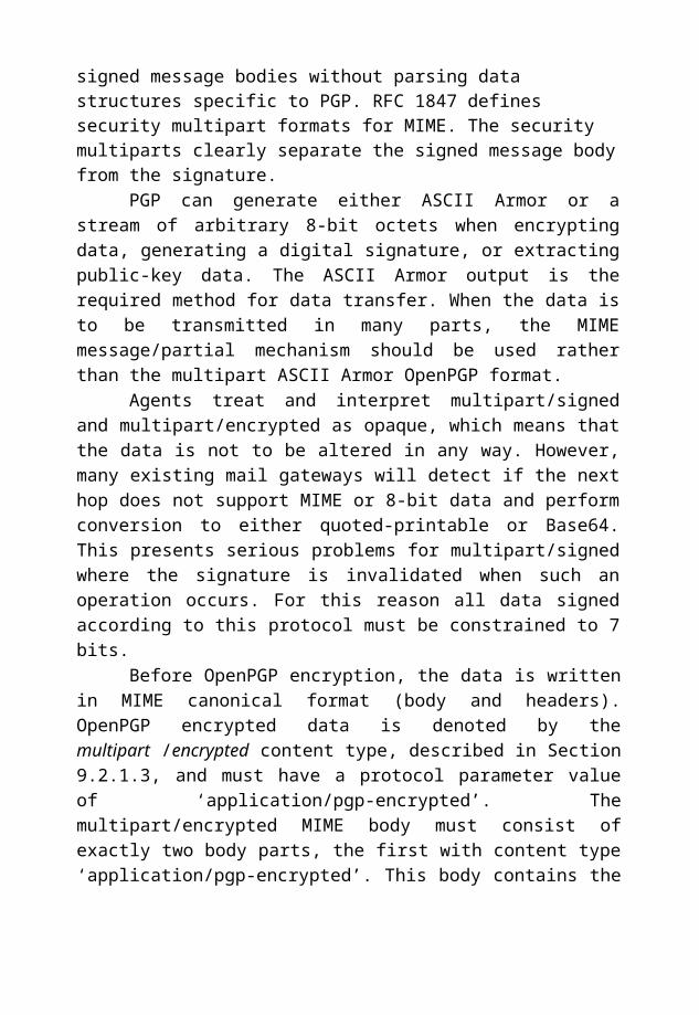
9.2.1.4 MIME Security with OpenPGP This subsection describes how the OpenPGP message format can be
used to provide privacy and authentication using the MIME security content type. The integrating work on PGP with MIME suffered from a number of problems, the most significant of which was the inability to recover signed message bodies without parsing data structures specific to PGP. RFC 1847 defines security multipart formats for MIME. The security multiparts clearly separate the signed message body from the signature.
PGP can generate either ASCII Armor or a stream of arbitrary 8-bit octets when encrypting data, generating a digital signature, or extracting public-key data. The ASCII Armor output is the required method for data transfer. When the data is to be transmitted in many parts, the MIME message/partial mechanism should be used rather than the multipart ASCII Armor OpenPGP format.
Agents treat and interpret multipart/signed and multipart/encrypted as opaque, which means that the data is not to be altered in any way. However, many existing mail gateways will detect if the next hop does not support MIME or 8-bit data and perform conversion to either quoted-printable or Base64. This presents serious problems for multipart/signed where the signature is invalidated when such an operation occurs. For this reason all data signed according to this protocol must be constrained to 7 bits.
Before OpenPGP encryption, the data is written in MIME canonical format (body and headers). OpenPGP encrypted data is denoted by the multipart /encrypted content type, described in Section 9.2.1.3, and must have a protocol parameter value of ‘application/pgp-encrypted’. The multipart/encrypted MIME body must consist of exactly two body parts, the first with content type ‘application/pgp-encrypted’. This body contains the control information. The second MIME body part must contain the actual encrypted data. It must be labelled with a content type of ‘application/octet-stream’.
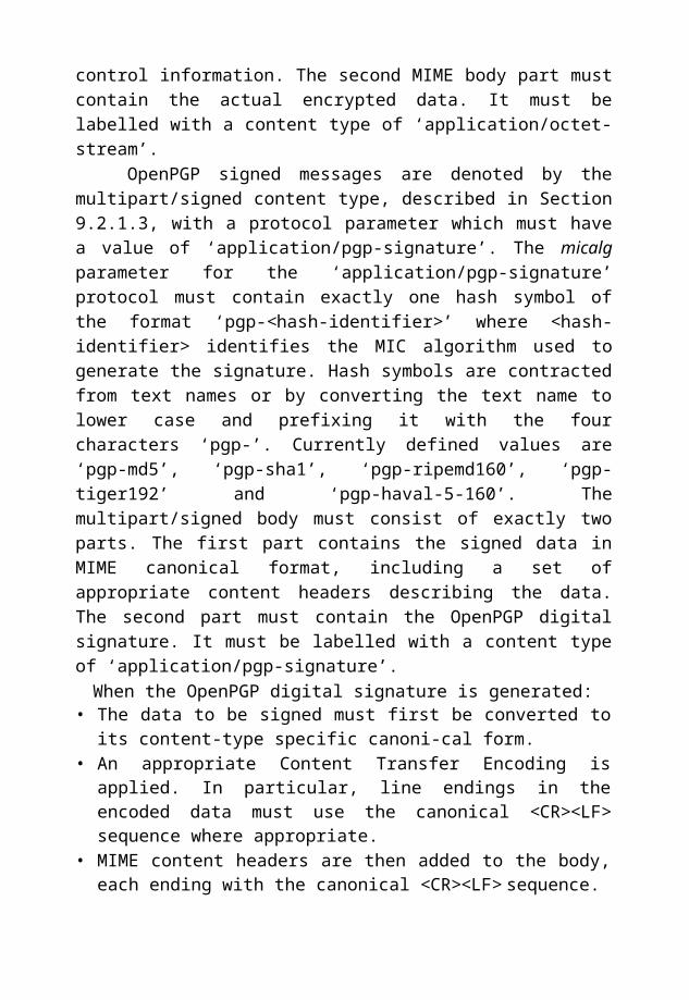
OpenPGP signed messages are denoted by the multipart/signed content type, described in Section 9.2.1.3, with a protocol parameter which must have a value of ‘application/pgp-signature’. The micalg parameter for the ‘application/pgp-signature’ protocol must contain exactly one hash symbol of the format ‘pgp-<hash-identifier>’ where <hash-identifier> identifies the MIC algorithm used to generate the signature. Hash symbols are contracted from text names or by converting the text name to lower case
and prefixing it with the four characters ‘pgp-’. Currently defined values are ‘pgp-md5’, ‘pgp-sha1’, ‘pgp-ripemd160’, ‘pgp-tiger192’ and ‘pgp-haval-5-160’. The multipart/signed body must consist of exactly two parts. The first part contains the signed data in MIME canonical format, including a set of appropriate content headers describing the data. The second part must contain the OpenPGP digital signature. It must be labelled with a content type of ‘application/pgp-signature’.
When the OpenPGP digital signature is generated:• The data to be signed must first be converted to its content-type specific
canoni-cal form. • An appropriate Content Transfer Encoding is applied. In particular, line
endings in the encoded data must use the canonical <CR><LF> sequence where appropriate.
• MIME content headers are then added to the body, each ending with the canonical <CR><LF> sequence.
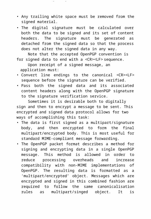
• Any trailing white space must be removed from the signed material. • The digital signature must be calculated over both the data to be signed
and its set of content headers. The signature must be generated as detached from the signed data so that the process does not alter the signed data in any way.
Note that the accepted OpenPGP convention is for signed data to end with a <CR><LF> sequence.
Upon receipt of a signed message, an application must:• Convert line endings to the canonical <CR><LF> sequence before the
signature can be verified. • Pass both the signed data and its associated content headers along with
the OpenPGP signature to the signature verification service. Sometimes it is desirable both to digitally sign and then to encrypt a
message to be sent. This encrypted and signed data protocol allows for two ways of accomplishing this task:• The data is first signed as a multipart/signature body, and then encrypted
to form the final multipart/encrypted body. This is most useful for standard MIME-compliant message forwarding.
• The OpenPGP packet format describes a method for signing and encrypting data in a single OpenPGP message. This method is allowed in order to reduce processing overheads and increase compatibility with non-MIME implementations of OpenPGP. The resulting data is formatted as a ‘multipart/encrypted’ object. Messages which are encrypted and signed in this combined fashion are required to follow the same canonicalisation rules as multipart/singed object. It is explicitly allowed
for an agent to decrypt a combined message and rewrite it as a multipart/signed object using the signature data embedded in the encrypted version.
A MIME body part of the content type ‘application/pgp-keys’ contains ASCII-Armour-ed transferable public-key packets as defined in RFC 2440.
Signatures of a canonical text document as defined in RFC 2440 ignore trailing white space in signed material. Implementations which choose to use signatures of canonical text documents will not be able to detect the addition of white space in transit.
S/MIMES/MIME provides a way to send and receive 7-bit MIME data. S/MIME can be used with any system that transports MIME data. It can also be used by traditional mail user agents (MUAs) to add cryptographic security services to mail that is sent, and to interpret cryptographic security services in mail that is received. In order to create S/MIME messages, an S/MIME agent has to follow the specifications discussed in this section, as well as the specifications listed in the cryptographic message syntax (CMS).
The S/MIME agent represents user software that is a receiving agent, a sending agent, or both. S/MIME version 3 agents should attempt to have the greatest interoperability possible with S/MIME version 2 agents. S/MIME version 2 is described in RFC 2311 to RFC 2315 inclusively.
Before using a public key to provide security services, the S/MIME agent must certify that the public key is valid. S/MIME agents must use the Internet X.509 Public-Key Infras-tructure (PKIX) certificates to validate public keys as described in the PKIX certificate and CRL profile.
9.2.2.1 Definitions
The following definitions are to be applied:
• ASN.1 : Abstract Syntax Notation One, as defined in ITU-T X.680 – 689. • BER: Basic Encoding Rules for ASN.1, as defined in ITU-T X.690. • DER: Distinguished Encoding Rules for ASN.1, as defined in ITU-T
X.690. • Certificate: A type that binds an entity’s distinguished name to a public
key with a digital signature. This type is defined in the PKIX certificate and CRL profile. The certificate also contains the distinguished name of the certificate issuer (the signer), an issuer-specific serial number, the
issuer’s signature algorithm identifier, a validity period and extensions also defined in that certificate.
• CRL: The Certificate Revocation List that contains information about certificates whose validity the issuer has prematurely revoked. The information consists of an issuer name, the time of issue, the next scheduled time of issue, a list of certificate serial numbers and their associated revocation times, and extensions as defined in Chapter 6. The CRL is signed by the issuer.
• Attribute certificate: An X.509 AC is a separate structure from a subject’s PKIX certificate. A subject may have multiple X.509 ACs associated with each of its PKIX certificates. Each X.509 AC binds one or more attributes with one of the subject’s PKIXs.
• Sending agent : Software that creates S/MIME CMS objects, MIME body parts that contains CMS objects, or both.
• Receiving agent : Software that interprets and processes S/MIME CMS objects, MIME parts that contain CMS objects, or both.
• S/MIME agent : User software that is a receiving agent, a sending agent, or both.
9.2.2.2 Cryptographic Message Syntax (CMS) Options CMS allows for a wide variety of options in content and algorithm
support. This sub-section puts forth a number of support requirements and recommendations in order to achieve a base level of interoperability among all S/MIME implementations. CMS pro-vides additional details regarding the use of the cryptographic algorithms.
Digest Algorithm IdentifierThis type identifies a message digest algorithm which maps the
message to the mes-sage digest. Sending and receiving agents must support SHA-1. Receiving agents should support MD5 for the purpose of providing backward compatibility with MD5-digested S/MIMEv2SignedData objects.SignatureAlgorithmIdentifier
Sending and receiving agents must support id-dsa defined in DSS. Receiving agents should support rsaEncryption, defined in PRCS-1.
KeyEncryptionAlgorithmIdentifierThis type identifies a key encryption algorithm under which a content
encryption key can be encrypted. A key-encryption algorithm supports encryption and decryption operations. The encryption operation maps a key string to another encrypted key string under the control of a key encryption
key.Sending and receiving agents must support Diffie – Hellman key
exchange. Receiving agents should support rsaEncryption. Incoming encrypted messages contain symmetric keys which are to be decrypted with a user’s private key. The size of the private key is determined during key generation. Sending agents should support rsaEncryption.
General syntaxThe syntax is to support six different content types: data, signed data,
enveloped data, signed-and-enveloped data, digested data and encrypted data. There are two classes of content types: base and enhanced. Content types in the base class contain just data with no cryptographic enhancement, categorised as the data content type. Content types in the enhanced class contain content of some type (possibly encrypted), and other cryptographic enhancements. These types employ encapsulation, giving rise to the terms outer content containing the enhancements and inner content being enhanced.
CMS defines multiple content types. Of these, only the data, signed data and enveloped data types are currently used for S/MIME.
• Data content type: This type is arbitrary octet strings, such as ASCII text files. Such strings need not have any internal structure.
The data content type should have ASN.1
type Data: Data ::= OCTET STRING
Sending agents must use the id-data content-type identifier to indicate the message content which has had security services applied to it.
• Signed-data content type: This type consists of any type and encrypted message digests of the content for zero or more signers. Any type of content can be signed by any number of signers in parallel. The encrypted digest for a signer is a digital signature on the content for that signer. Sending agents must use the signed-data content type to apply a digital signature to a message or in a degenerate case where there is no signature information to convey certificates. The syntax has a degenerate case in which there are no signers on the content. This degenerate case provides a means to disseminate certificates and certificate-revocation lists.
The process to construct signed data is as follows. A message digest is computed on the content with a signer-specific message digest algorithm. A digital signature is formed by taking the message digest of
the content to be signed and then encrypting it with the private key of the signer. The content plus signature are then encoded using Base64 encoding. A recipient verifies the signed-data message by decrypting the encrypted message digest for each signer with the signer’s public key, then com-paring the recovered message digest to an independently computed message digest. The signer’s public key is either contained in a certificate included in the signer information, or referenced by an issuer distinguished name and an issuer-specific serial number that uniquely identify the certificate for the public key.
• Enveloped-data content type: An application/prcs7-mime subtype is used for the en-veloped-data content type. This content type is used to apply privacy protection to a message. The type consists of encrypted content of any type and encrypted-content encryption keys for one or more recipients. The combination of encrypted content and encrypted content-encryption key for a recipient is called a digital envelope for that recipient. Any type of content can be enveloped for any number of recipients in parallel. If a sending agent is composing an encrypted message to a group of recipients, that agent is forced to send more than one message.
The process by which enveloped data is constructed involves the following:
– A content-encryption key (a pseudo-random session key) is generated at random and is encrypted with the recipient’s public key for each recipient.
– The content is encrypted with the content-encryption key. Content encryption may require that the content be padded to a multiple of some block size.
– The recipient-specific information values for all the recipients are combined with the encrypted content into an EnvelopedData value. This information is then encoded into Base64.
To cover the encrypted message, the recipient first strips off the Base64 encod-ing. The recipient opens the envelope by decrypting one of the encrypted content-encryption keys with the recipient’s private key and decrypting the encrypted content with the recovered content-encryption key (the session key).
A sender needs to have access to a public key for each intended message recipient to use this service. This content type does not provide authentication.
• Digested-data content type: This type consists of content of any type and a message digest of the content. A typical application of the digested-data content type is to add integrity to content of the data content type, and the result becomes the content input to the enveloped-data content type. A message digest is computed on the content with a message digest algorithm. The message digest algorithm and the message digest are combined with the content into a DigestedData value.
A recipient verifies the message digest by comparing the message digest to an independently computed message digest.
• Encrypted-data content type: This type consists of encrypted content of any type. Unlike the enveloped-data content type, the encrypted-data content type has neither recipients nor encrypted content-encryption keys. Keys are assumed to be managed by other means. • It is expected that a typical application of the encrypted-data content
type will be to encrypt content of the data content type for local storage, perhaps where the encryption key is a password.
9.2.3 Enhanced Security Services for S/MIMEThe security services described in this section are extensions to
S/MIME version 3. Some of the features of each service use the concept of a triple wrapped message. A triple wrapped message is one that has been signed, then encrypted and then signed again. The signers of the inner and outer signatures may be different entities or the same entity. The S/MIME specification does not limit the number of nested encapsulations, so there may be more than three wrappings.
The inside signature is used for content integrity, non-repudiation with proof of origin, and binding attributes to the original content. These attributes go from the originator to the recipient, regardless of the number of intermediate entities such as mail list agents that process the message. Signed attributes can be used for access control to the inner body. The encrypted body provides confidentiality, including confidentiality of the attributes that are carried in the inside signature.
The outside signature provides authentication and integrity for information that is pro-cessed hop by hop, where each hop is an intermediate entity such as a mail list agent. The outer signature binds attributes to the encrypted body. These attributes can be used for access control and routing decisions.
9.2.3.1 Triple Wrapped Message The steps to create a triple wrapped message are as follows:
1. Start with the original content (a message body). 2. Encapsulate the original content with the appropriate MIME content-type
headers. 3. Sign the inner MIME headers and the original content resulting from step
2. 4. Add an appropriate MIME construct to the signed message from step 3.
The resulting message is called the inside signature.
– If it is signed using multipart/signed, the MIME construct added consists of a content type of multipart/signed with parameters, the boundary, the step 2 result, a content type of application/pkcs7-signature, optional MIME headers, and a body part that is the result of step 3.
– If it is instead signed using application/pkcs7-mime, the MIME construct added consists of a content type of application/pkcs7-mime with parameters, optional MIME headers and the result of step 3.
5. Encrypt the step 4 result as a single block, turning it into an application/pkcs7-mime object.
6. Add the appropriate MIME headers: a content type of application/pkcs7-mime with parameters, and optional MIME headers such as Content-Transfer-Encoding and Content-Disposition.
7. Sign the step 6 result (the MIME headers and the encrypted body) as a single block.
8. Using the same logic as in step 4, add an appropriate MIME construct to the signed message from step 7. The resulting message is called the outside signature, and is also the triple wrapped message.
A triple wrapped message has many layers of encapsulation. The structure differs depending on the choice of format for the signed portions of the message. Because of the way that MIME encapsulates data, the layers do not appear in order, and the notion of layers becomes vague.
There is no need to use the multipart/signed format in an inner signature because it is known that the recipient is able to process S/MIME messages. A sending agent might choose to use the multipart/signed format in the outer layer so that a non-S/MIME agent could see that the next inner layer is encrypted. Because many sending agents always use multipart/signed structures, all receiving agents must be able to interpret either multipart/signed or application/pkcs7-mime signature structures.
9.2.3.2 Security Services with Triple Wrapping This subsection briefly describes the relationship of each service with
triple wrapping. If a signed receipt is requested for a triple wrapped message, the receipt request must be in the inside signature, not in the outside signature. A secure mailing list agent may change the receipt policy in the outside signature of a triple wrapped message when the message is processed by the mailing list.
A security label is included in the signed attributes of any SignedData object. A security label attribute may be included in either the inner signature or the outer signature, or both.
The inner security label is used for access control decisions related to the original plaintext content. The inner signature provides authentication and cryptographically pro-tects the integrity of the original signer’s security label that is in the inside body. The confidentiality security service can be applied to the inner security label by encrypting the entire inner SignedData block within an EnvelopedData block. The outer security label is used for access control and routing decisions related to the encrypted message.
Secure mail list message processing depends on the structure of S/MIME layers present in the message sent to the mail list agent. The agent never changes the data that was hashed to form the inner signature, if such a signature is present. If an outer signature is present, then the agent will modify the data that was hashed to form that outer signature.
Contain attributes should be placed in the inner or outer SignedData message. Some attributes must be signed, while signing is optional for others, and some attributes must not be signed.
Some security gateways sign messages that pass through them. If the message is of any type other than a SignedData type, the gateway has only one way to sign the message by wrapping it with a SignedData block and MIME headers. If the message to be signed by the gateway is a SignedData message already, the gateway can sign the message by inserting SignerInfo into the SignedData block.
9.2.3.3 Signed Receipts Returning a signed receipt provides to the originator proof of
delivery of a message, and allows the originator to demonstrate to a third party that the recipient was able toverify the signature of the original message. This receipt is bound to the original message through the signature. Consequently, this service may be requested only if a message is signed. The receipt sender may optionally also encrypt a receipt to provide confidentiality between the sender and recipient
of the receipt.The originator of a message may request a signed receipt from the
message’s recipients. The request is indicated by adding a receiptRequest attribute to the signedAttributes field of the SignerInfo object for which the receipt is requested. The receiving user agent software should automatically create a signed receipt when requested to do so, and return the receipt in accordance with mailing list expansion options, local security policies and configuration options.
Receipts involve the interaction of two parties: the sender and the receiver. The sender is the agent that sent the original message that includes a request for a receipt. The receiver is the party that received that message and generated the receipt.
The interaction steps in a typical transaction are:1. Sender creates a signed message including a receipt request attribute. 2. Sender transmits the resulting message to the recipient(s). 3. Recipient receives message and determines if there are a valid signature
and receipt request in the message. 4. Recipient creates a signed receipt. 5. Recipient transmits the resulting signed receipt message to the sender. 6. Sender receives the message and validates that it contains a signed
receipt for the original message.
9.2.3.4 Receipt Request Creation Multilayer S/MIME messages may contain multiple SignedData
layers. Receipts are requested only for the innermost SignedData layer in a multilayer S/MIME message such as a triple wrapped message. Only one receipt request attribute can be included in the signedAttributes of SignerInfo.
Internet Firewalls for Trusted SystemsA firewall is a device or group of devices that controls access
between networks. A firewall generally consists of filters and gateway(s), varying from firewall to firewall. It is a security gateway that controls access between the public Internet and an intranet (a private internal network) and is a secure computer system placed between a trusted network and an untrusted internet. A firewall is an agent which screens network traffic in some way, blocking traffic it believes to be inappropriate, dangerous, or both. The security concerns that inevitably arise between the sometimes hostile Internet and secure intranets are often dealt with by inserting one or more
firewalls in the path connecting the Internet and the internal network. In reality, Internet access provides benefits to individual users, government agencies and most organisations. But this access often creates a threat as a security flaw. The protective device that has been widely accepted is the firewall. When inserted between the private intranet and the public Internet it establishes a controlled link and erects an outer security wall or perimeter. The aim of this wall is to protect the intranet from Internet-based attacks and to provide a choke point where security can be imposed.
Firewalls act as an intermediate server in handling SMTP and HTTP connections in either direction. Firewalls also require the use of an access negotiation and encapsulation protocol such as SOCKS to gain access to the Internet, the intranet, or both. Many firewalls support tri-homing, allowing use of a DMZ network. It is possible for a firewall to accommodate more than three interfaces, each attached to a different network segment.
Firewalls can be classified into three main categories: packet filters, circuit-level gate-ways and application-level gateways.
10.1 Role of FirewallsThe firewall imposes restrictions on packets entering or leaving the
private network. All traffic from inside to outside, and vice versa, must pass through the firewall, but only authorised traffic will be allowed to pass. Packets are not allowed through unless they conform to a filtering specification, or unless there is negotiation involving some sort of authentication. The firewall itself must be immune to penetration.
Firewalls create checkpoints (or choke points) between an internal private network and an untrusted Internet. Once the choke points have been clearly established, the device can monitor, filter and verify all inbound and outbound traffic.
The firewall may filter on the basis of IP source and destination addresses and TCP port number. Firewalls may block packets from the Internet side that claim a source address of a system on the intranet, or they may require the use of an access negotiation and encapsulation protocol like SOCKS to gain access to the intranet.
The means by which access is controlled relate to using network layer or transport layer criteria such as IP subnet or TCP port number, but there is no reason that this must always be so. A growing number of firewalls control access at the application layer, using user identification as the criterion. In addition, firewalls for ATM networks may control access based on the data link layer criteria.
The firewall also enforces logging, and provides alarm capacities as
well. By placing logging services at firewalls, security administrators can monitor all access to and from the Internet. Good logging strategies are one of the most effective tools for proper network security.
Firewalls may block TELNET or RLOGIN connections from the Internet to the intranet. They also block SMTP and FTP connections to the Internet from internal systems not authorised to send e-mail or to move files.
The firewall provides protection from various kinds of IP spoofing and routing attacks. It can also serve as the platform for IPsec. Using the tunnel mode capability, the firewall can be used to implement Virtual Private Networks (VPNs). A VPN encapsulates all the encrypted data within an IP packet.
A firewall can limit network exposure by hiding the internal network systems and information from the public Internet.
The firewall is a convenient platform for security-unrelated events such as a network address translator (which maps local addresses to Internet addresses) and has a network management function that accepts or logs Internet usage.
The firewall certainly has some negative aspects: it cannot protect against internal threats such as an employee who cooperates with an external attacker; it is also unable to protect against the transfer of virus-infected programs or files because it is impossible for it to scan all incoming files, e-mail and messages for viruses. However, since a firewall acts as a protocol endpoint, it may use an implementation methodology designed to minimise the likelihood of bugs.
A firewall can effectively implement and control the traversal of IP multicast traffic. Some firewall mechanisms such as SOCKS are less appropriate for multicast because they are designed specifically for unicast traffic.
10.2 Firewall-Related TerminologyTo design and configure a firewall, some familiarity with the basic
terminology is required. It is useful for readers to understand the important terms commonly applicable to firewall technologies.
10.2.1 Bastion HostA bastion host is a publicly accessible device for the network’s
security, which has a direct connection to a public network such as the Internet. The bastion host serves as a platform for any one of the three types of firewalls: packet filter, circuit-level gateway or application-level gateway.
Bastion hosts must check all incoming and outgoing traffic and enforce the rules specified in the security policy. They must be prepared for attacks from external and possibly internal sources. They should be built with the least amount of hardware and software in order for a potential hacker to have less opportunity to overcome the firewall. Bastion hosts are armed with logging and alarm features to prevent attacks.
The bastion host’s role falls into the following three common types:
• Single-homed bastion host : This is a device with only one network interface, normally used for an application-level gateway. The external router is configured to send all incoming data to the bastion host, and all internal clients are configured to send all outgoing data to the host. Accordingly, the host will test the data according to security guidelines.
• Dual-homed bastion host : This is a firewall device with at least two network interfaces. Dual-homed bastion hosts serve as application-level gateways, and as packet filters and circuit-level gateways as well. The advantage of using such hosts is that they create a complete break between the external network and the internal network. This break forces all incoming and outgoing traffic to pass through the host. The dual-homed bastion host will prevent a security break-in when a hacker tries to access internal devices.
• Multihomed bastion host : Single-purpose or internal bastion hosts can be classified as either single-homed or multihomed bastion hosts. The latter are used to allow the user to enforce strict security mechanisms. When the security policy requires all inbound and outbound traffic to be sent through a proxy server, a new proxy server should be created for the new streaming application. On the new proxy server, it is necessary to implement strict security mechanisms such as authentication. When multihomed bastion hosts are used as internal bastion hosts, they must reside inside the organisation’s internal network, normally as application gateways that receive all incoming traffic from external bastion hosts. They provide an additional level of security in case the external firewall devices are compromised. All the internal network devices are configured to communicate only with the internal bastion host.
• A tri-homed firewall connects three network segments with different network addresses. This firewall may offer some security advantages over firewalls with two interfaces. An attacker on the unprotected Internet may compromise hosts on the DMZ but still not reach any hosts on the protected internal network.
10.2.2 Proxy ServerProxy servers are used to communicate with external servers on
behalf of internal clients. A proxy service is set up and torn down in response to a client request, rather thanexisting on a static basis. The term proxy server typically refers to an application-level gateway, although a circuit-level gateway is also a form of proxy server. The gateway can be configured to support an application-level proxy on inbound connections and a circuit-level proxy on outbound connections. Application proxies forward packets only when a connection has been established using some known protocol. When the connection closes, a firewall using application proxies rejects individual packets, even if they contain port numbers allowed by a rule set. In contrast, circuit proxies always forward packets containing a given port number if that port number is permitted by the rule set. Thus, the key difference between application and circuit proxies is that the latter are static and will always set up a connection if the DUT/SUT’s rule set allows it. Each proxy is configured to allow access only to specific host systems.
The audit log is an essential tool for detecting and terminating intruder attacks. There-fore, each proxy maintains detailed audit information by logging all traffic, each connec-tion and the duration of each connection.
Since a proxy module is a relatively small software package specifically designed for network security, it is easier to check such modules for security flaws.
Each proxy is independent of other proxies on the bastion host. If there is a problem with the operation of any proxy, or if future vulnerability is discovered, it is easy to replace the proxy without affecting the operation of the proxy’s applications. If the support of a new service is required, the network administrator can easily install the required proxy on the bastion host.
A proxy generally performs no disk access other than to read its initial configuration file. This makes it difficult for an intruder to install Trojan horse sniffers or other dangerous files on the bastion host.
10.2.3 SOCKS The SOCKS protocol version 4 provides for unsecured firewall
traversal for TCP-based client/server applications, including HTTP, TELNET and FTP. The new protocol extends the SOCKS version 4 model to include UDP, and allows the framework to include pro-vision for generalised strong authentication schemes, and extends the addressing
scheme to encompass domain name and IPv6 addresses. The implementation of the SOCKS pro-tocol typically involves the recompilation or relinking of TCP-based client applications so that they can use the appropriate encapsulation routines in the SOCKS library (refer to RFC 1928).
When a TCP-based client wishes to establish a connection to an object that is reachable only via a firewall, it must open a TCP connection to the appropriate SOCKS port on the SOCKS server system. The SOCKS service is conventionally located at TCP port 1080. If the connection request succeeds, the client enters negotiation for the authentication method to be used, authenticates with the chosen method, and then sends a relay request. The SOCKS server evaluates the request, and either establishes the appropriate connection or denies it. In fact, SOCKS defines how to establish authenticated connections, but currently it does not provide a clear-cut solution to the problem of encrypting the data traffic. Since the Internet at large is considered a hostile medium, encryption by using ESP is also assumed in this scenario. An ESP transform that provides both authentication and encryption could be used, in which case the AH need not be included.
10.2.4 Choke PointThe most important aspect of firewall placement is to create choke
points. A choke point is the point at which a public internet can access the internal network. The most comprehensive and extensive monitoring tools should be configured on the choke points. Proper implementation requires that all traffic be funnelled through these choke points. Since all traffic is flowing through the firewalls, security administrators, as a firewall strategy, need to create choke points to limit external access to their networks. Once these choke points have been clearly established, the firewall devices can monitor, filter and verify all inbound and outbound traffic.
Since a choke point is installed at the firewall, a prospective hacker will go through the choke point. If the most comprehensive logging devices are installed in the firewall itself, all hacker activities can be captured. Hence, this will detect exactly what a hacker is doing.
10.2.5 De-militarised Zone (DMZ)The DMZ is an expression that originates from the Korean War. It
meant a strip of land forcibly kept clear of enemy soldiers. In terms of a firewall, the DMZ is a network that lies between an internal private network and the external public network. DMZ networks are sometimes called perimeter networks. A DMZ is used as an additional buffer to further
separate the public network from the internal network.A gateway is a machine that provides relay services to compensate
for the effects of a filter. The network inhabited by the gateway is often called the DMZ. A gateway in the DMZ is sometimes assisted by an internal gateway. The internal filter is used to guard against the consequences of a compromised gateway, while the outside filter can be used to protect the gateway from attack.
Many firewalls support tri-homing, allowing use of a DMZ network. It is possible for a firewall to accommodate more than three interfaces, each attached to a different network segment.
10.2.6 Logging and Alarms Logging is usually implemented at every device in the firewall, but
these individual logs combine to become the entire record of user activity. Packet filters normally do not enable logging by default so as not to degrade performance. Packet filters as well as circuit-level gateways log only the most basic information. Since a choke point is installed at the firewall, a prospective hacker will go through the choke point. If so, the comprehensive logging devices will probably capture all hacker activities, including all user activities as well. The user can then tell exactly what a hacker is doing, and have such information available for audit. The audit log is an essential tool for detecting and terminating intruder attacks.
Many firewalls allow the user to preconfigure responses to unacceptable activities. The firewall should alert the user by several means. The two most common actions are for the firewall to break the TCP/IP connection, or to have it automatically set off alarms.
10.2.7 VPNSome firewalls are now providing VPN services. VPNs are
appropriate for any organ-isation requiring secure external access to internal resources. All VPNs are tunnelling protocols in the sense that their information packets or payloads are encapsulated or tun-nelled into the network packets. All data transmitted over a VPN is usually encrypted because an opponent with access to the Internet could eavesdrop on the data as it trav-els over the public network. The VPN encapsulates all the encrypted data within an IP packet. Authentication, message integrity and encryption are very important fundamen-tals for implementing a VPN. Without such authentication procedures, a hacker could impersonate anyone and then gain access to the network. Message integrity is required because the packets can be altered as they travel through the Internet. Without
encryption, the information may become truly public. Several methods exist to implement a VPN. Windows NT or later versions support a standard RSA connection through a VPN. Spe-cialised firewalls or routers can be configured to establish a VPN over the Internet. New protocols such as IPsec are expected to standardise on a specific VPN solution. Several VPN protocols exist, but the Point-to-Point Tunnelling Protocol (PPTP) and IPsec are the most popular.
10.3 Types of FirewallsAs mentioned above, firewalls are classified into three common
types: packet filters, circuit-level gateways and application-level gateways. We examine each of these in turn.
10.3.1 Packet Filters Packet filters are one of several different types of firewalls that
process network traffic on a packet-by-packet basis. A packet filter’s main function is to filter traffic from a remote IP host, so a router is needed to connect the internal network to the Internet. A packet filter is a device which inspects or filters each packet at a screening router for the content of IP packets. The screening router is configured to filter packets from entering or leaving the internal network, as shown in Figure 10.1. The routers can easily compare each IP address to a filter or a series of filters. The type of router used in a packet-filtering firewall is known as a screening router.
Internet
Inside net 1
Inside net 2
Inside net 3
Screening routerFigure 10.1 A screening router for packet filtering.
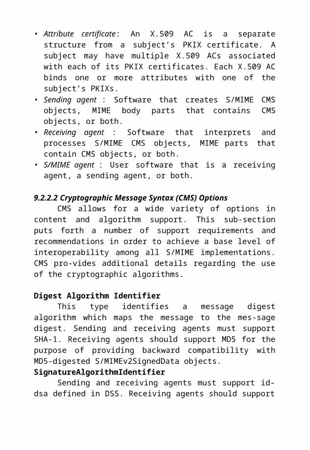
Packet filters typically set up a list of rules that are sequentially read line by line. Filtering rules can be applied based on source and destination IP addresses or network addresses, and TCP or UDP ports. Packet filters are read and then treated on a rule-by-rule basis. A packet filter will provide two actions, forward or discard. If the action is in the forward process, the action takes place to route the packet as normal if all conditions within the rule are met. The discard action will block all packets if the conditions in the rule are not met. Thus, a packet filter is a device that inspects each packet for predefined content. Although it does not provide an error-correcting ability, it is almost always the first line of defence. When packets are filtered at the external filter, it is usually called a screening router.
Since a packet filter can restrict all inbound traffic to a specific host, this restriction may prevent a hacker from being able to contact any other host within the internal network. However, the significant weakness with packet filters is that they cannot discriminate between good and bad packets. Even if a packet passes all the rules and is routed to the destination, packet filters cannot tell whether the routed packet contains good or malicious data. Another weakness of packet filters is their susceptibility to spoofing. In IP spoofing, an attacker sends packets with an incorrect source address. When this happen, replies will be sent to the apparent source address, not to the attacker. This might seem to be a problem.
10.3.1.1 Packet-Filtering Rules A packet filter applies a set of rules to each incoming IP packet and
then forwards or discards the packet. The packet filter typically sets up a list of rules which may match fields in the IP or TCP header. If there is a match to one of the rules, that rule is able to determine whether to forward or discard the packet. If there is no match to any rule, then two default actions (forward and discard) will be taken.
TELNET packet filteringTELNET is a simple remote terminal access that allows a user to log
onto a computer across an internet. TELNET establishes a TCP connection, and then passes keystrokes from the user’s keyboard directly to the remote computer as if they had been typed on a keyboard attached to the remote machine. TELNET also carries output from the remote machine back to the user’s screen. TELNET client software allows the user to specify a remote machine either by giving its domain name or IP address.
TELNET can be used to administer a UNIX machine. Windows NT does not provide a TELNET serve with the default installation, but a third-
party service can be easily added. TELNET sends all user names and passwords in plaintext. Experienced hackers can hijack a TELNET session in progress. TELNET should only be used when the user can verify the entire network connecting the client and server, not over the Internet. All TELNET traffic should be filtered at the firewall. TELNET runs on TCP port 23.
For example, to disable the ability to TELNET into internal devices from the Internet, the information listed Table 10.1 tells the router to discard any packet going to or coming from TCP port 23. TELNET for remote access application runs on TCP port 23. It runs
Table 10.1 Telnet packet-filtering example
Rule Action Source Source Destination Destination Protocolnumber IP port IP port
1 Discard * 23 * * TCP2 Discard * * * 23 TCP
completely in open non-encryption, with no authentication other than the user name and password that are transmitted in clear. An asterisk (*) in a field indicates any value in that particular field. The packet-filtering rule sets are executed sequentially, from top to bottom.
If a packet is passed through the filter and has a source port of 23, it will immediately be discarded. If a packet with a destination port of 23 is passed through this filter, it is discarded only after rule 2 has been applied. All other packets will be discarded.
FTP packet filteringIf the FTP service is to apply the same basic rule as applied to
TELNET, the packet filter to allow or block FTP would look like Table 10.2. The FTP service is typically associated with using TCP ports 20 and 21.
One approach to handling FTP connections is explained with the following rule set. Rule 1 allows any host with the network address 192.168.10.0 to initiate a TCP session on any destination IP address on port 21. Rule 2 blocks any packet originating from any remote address with a source port of 20 and contacting a host with a network address 192.168.10.0 on any port less than 1024. Rule 3 allows any remote address that has a source port of 20 and is contacting any host with a network address of 192.168.10.0 on any port. Once a connection is set up, the ACK flag (ACK = 1) of a TCP segment is set to acknowledge segments sent from the other side. If any packet violates rule 2, it will be immediately discarded, and rule
3 will never be executed.With FTP, two TCP connections are used: a control connection to set
up the file transfer and a data connection for the actual file transfer. The data connection uses a different port number to be assigned for the transfer. Remember that most servers live on low-numbered ports, but most outgoing calls tend to use higher-numbered ports, typically above 1024.
FTP is the first protocol for transferring or moving files across the Internet. Like many of the TCP/IP protocols, FTP was not designed with security in mind. It communicates
Table 10.2 FTP packet-filtering example
Rule Action Source Source Destination Destination Protocolnumber IP port IP port
1 Allow 192.168.10.0 * * 21 TCP2 Block * 20 192.168.10.0 <1024 TCP3 Allow * 20 192.168.10.0 * TCP
ACK = 1
with the server on two separate TCP ports 20 and 21. Each FTP server has a command channel, where the requests for data and directory listings are issued, and a data channel, over which the requested data is delivered.
FTP operates in two different modes (active and passive). In active mode, an FTP server receives commands on TCP/IP port 21 and exchanges data with the client. When a client contacts an FTP server in active mode and wants to send or receive data, the client picks an unused local TCP port between 1024 and 65 535, tells the server over the command channel, and listens for the server to connect on the chosen port. The server opens a connection from TCP port 20 to the specified port on the client machine. Once the connection is established, the data is passed across.
In passive mode, the command channel is still port 21 on the server, but the traditional data channel on port 20 is not used. Instead, when the client requests passive mode, the server picks an unused local TCP port between 1024 and 65 535 and tells the client. The client opens a connection to that port on the server. The server is listening on that port for the inbound connection from the client. Once the connection is established, the data flows across. Thus, since the client is initiating both the command and data channel connections to the server, most modern browsers use passive mode FTP for data accessing.
SMTP packet filtering
The sending and transmission of mail is the responsibility of a Mail Transport Agent (MTA). The protocol behind nearly all MTAs is SMTP and its extension ESMTP. On the Internet, e-mail exchanges between mail servers are handled with SMTP. It is the protocol that transfers e-mail from one server to another, and it provides a basic e-mail facility for transferring messages among separate hosts. A host’s SMTP server accepts mail and examines the destination IP address to decide whether to deliver the mail locally or to forward it to some other machine.
SMTP is a store/forward system, and such systems are well suited to firewall appli-cations. SMTP receivers use TCP port 25; SMTP senders use a randomly selected port above 1023.
Most e-mail messages are addressed with hostnames instead of IP addresses, and the SMTP server uses DNS (Directory and Naming Services) to determine the matching IP address. If the same machines handle internal and external mail delivery, a hacker who can spoof DNS information may be able to cause mail that was intended for internal destinations to be delivered to an external host. A hacker who can manipulate DNS responses can redirect mail to a server under the control of the hacker. That server can then copy the mail and return it. This will introduce delays and will usually leave a trail in the log or message headers. Therefore, if it is desired to avoid situations where internal and external mail delivery are handled on the machine and internal names are resolved through DNS, it will be good practice to have the best configuration in which there is an external mail server and a separate internal mail server. The external mail server has the IP address of the internal mail server configured via a host file.
Sendmail (www.sendmail.org/) is the mailer commonly used on UNIX systems. Send-mail is very actively supported on security issues, and has both an advantage and a disadvantage. Table 10.3 displays some examples of SMTP packet-filtering rule sets.
Table 10.3 SMTP packet-filtering examples
Case Action Source Source Destination Destination Protocolhost port host port
A Allow Source gateway 25 * * TCPB Allow * * * 25 TCPC Allow Internal host * * 25 TCPD Allow * 25 * * TCP ACK flag
Case A: Connection to source SMTP port. Port 25 is for SMTP incoming. Inbound mail is allowed, but only to a gateway host.
Case B: Connection to destination SMTP port. This rule set is intended to specify that any source host can send mail to the destination. A TCP packet with a destination port 25 is routed to the SMTP server on the
destination machine.Case C: This rule set achieves the intended result that was not achieved in B. The rule takes advantage of a feature
of TCP connection. This rule set states that it allows IP packets where the source IP address is one of a list of designated internal hosts and the destination TCP port 25.
Case D: This rule takes advantage of a feature of TCP connections. Once a connection is set up, the ACK flag of a TCP segment is set to acknowledge segments sent from the destination. It also allows incoming packets with a source port number of 25 that include that ACK flag in the TCP segment.
Packet filters offer their services at the network, transport and session layers of the OSI model. Packet filters forward or deny packets based on information in each packet’s header, such as the IP address or TCP port number. A packet-filtering firewall uses a rule set to determine which traffic should be forwarded and which should be blocked. Packet filters are then composed of rules that are read and treated on a rule-by-rule basis. Therefore, packet filtering is defined as the process of controlling access by examining packets based on the content of packet headers.
The following two subsections outline the specific details with relation to the circuit-level and application-level gateways for respective proxy services. Proxying provides Internet access for a single host or a small number of hosts. The proxy server eval-uates requests from the client and decides which to pass on and which to disregard. If a request is approved, the proxy server talks to the real server on behalf of the client and proceeds to relay requests from the client to the real server, and to relay the real server’s answers back to the client. The concept of proxies is very important to firewall application because a proxy replaces the network IP address with another contingent address.
Proxies are classified into two basic forms:• Circuit-level gateway • Application-level gateway
Both circuit and application gateways create a complete break between the internal premises network and external Internet. This break allows the firewall system to examine everything before passing it into or out of the internal network. Each of these gateways will be examined in turn in the following.
10.3.2 Circuit-Level Gateways The circuit-level gateway represents a proxy server that statically
defines what traffic will be forwarded. Circuit proxies always forward packets containing a given port number if that port number is permitted by the rule set. A circuit-leval gateway operates at the network level of the OSI model. This gateway acts as an IP address translator between the Internet and the internal system. The main advantage of a proxy server is its ability to provide Network Address Translation (NAT). NAT hides the internal IP
address from the Internet. NAT is the primary advantage of circuit-level gateways and provides secu-rity administrators with great flexibility when developing an address scheme internally. Circuit-level gateways are based on the same principles as packet filter firewalls. When the internal system sends out a series of packets, these packets appear at the circuit-level gateway where they are checked against the predetermined rules set. If the packets do not violate any rules, the gateway sends out the same packets on behalf of the internal system. The packets that appear on the Internet originate from the IP address of the gateway’s external port which is also the address that receives any replies. This process efficiently shields all internal information from the Internet. Figure 10.2 illustrates the circuit-level gateway for setting up two TCP connections.
10.3.3 Application-Level Gateways The application-level gateway represents a proxy server, performing
at the TCP/IP appli-cation level, that is set up and torn down in response to a client request, rather than existing on a static basis. Application proxies forward packets only when a connection has been established using some known protocol. When the connection closes, a fire-wall using application proxies rejects individual packets, even if the packets contain port numbers allowed by a rule set.
The application gateway analyses the entire message instead of individual packets when sending or receiving data. When an inside host initiates a TCP/IP connection, the application gateway receives the request and checks it against a set of rules or filters. The application gateway (or proxy server) will then initiate a TCP/IP connection with the remote server. The server will generate TCP/IP responses based on the request from the proxy server. The responses will be sent to the proxy server (application gateway) where the responses are again checked against the proxy server’s filters. If the remote server’s response is permitted, the proxy server will then forward the response to the inside host.
Outside Insideconnection connection
Circuit-levelgateway
TCP user on TCP user onAn IP address translator inner hostoutside host
Figure 10.2 Circuit-level gateway for setting up two TCP connections.
Application - levelgateway Private
Internet network
FTPTELNET
DNSSMTPHTTP
Outside Inside hosthost
A relay of application - leveltraffic
Figure 10.3 Application-level gateway for acting as a relay of application-level traffic.
Certain transport layer protocols work better than others. For example, TCP can easily be used through a proxy server because it is a connection-based protocol, while each UDP packet should be treated as an individual message because UDP is connectionless. The proxy server must analyse each UDP packet and apply it to the filters separately, which slows down the proxy process. ICMP programs are nearly impossible to proxy because ICMP messages do not work through an application-level gateway. For example, HTTP traffic is often used in conjunction with proxy servers, but an internal host could not ping a remote host through the proxy server. Application gateways (proxy servers) are used as intermediate devices when routing SMTP traffic to and from the internal network and the Internet.
The main advantage of a proxy server is its ability to provide NAT for shielding the internal network from the Internet. Figure 10.3 illustrates the application-level gateway acting as a relay of the application-level traffic.
10.4 Firewall DesignsThis section concerns how to implement a firewall strategy. The
primary step in designing a secure firewall is obviously to prevent the firewall devices from being compromised by threats. To provide a certain level of security, the three basic firewall designs are considered: a single-homed bastion host, a dual-homed bastion host and a screened subnet firewall. The first two options are for creating a screened host firewall, and the third option contains an additional packet-filtering router to achieve another level of security.
To achieve the most security with the least amount of effort is always desirable. When building firewall devices, the bastion host should
keep the design simple with the fewest possible components, both hardware and software. A bastion host is a publicly accessible device. When Internet users attempt to access resources on the Internet network, the first device they encounter is a bastion host. Fewer running services on the bastion host will give a potential hacker less opportunity to overcome the firewall. Bastion hosts must check all incoming and outgoing traffic and enforce the rules specified in the security policy. Bastion hosts are armed with logging and alarm features to prevent attacks. When creating a bastion host, it must be kept in mind that its role will help to decide what is needed and how to configure the device.
10.4.1 Screened Host Firewall (Single-Homed Bastion Host)The first type of firewall is a screened host which uses a single-
homed bastion host plus a packet-filtering router, as shown in Figure 10.4. Single-homed bastion hosts can be configured as either circuit-level or application-level gateways. When using either of these two gateways, each of which is called a proxy server, the bastion host can hide the configuration of the internal network.
NAT is essentially needed for developing an address scheme internally. It is a critical component of any firewall strategy. It translates the internal IP addresses to IANA-registered addresses to access the Internet. Hence, using NAT allows network admin-istrators to use any internal IP address scheme.
The screened host firewall is designed such that all incoming and outgoing information is passed through the bastion host. The external screening router is configured to route all incoming traffic directly to the bastion host as indicated in Figure 10.4. The screening router is also configured to route outgoing traffic only if it originates from the bastion host. This kind of configuration prevents internal clients from bypassing the bastion host. Thus, the bastion host is configured to restrict unacceptable traffic and proxy acceptable traffic.
A single-homed implementation may allow a hacker to modify the router not to forward packets to the bastion host. This action would bypass the bastion host and allow the hacker directly into the network. But such a bypass usually does not happen because a network using a single-homed bastion host is normally configured to send packets only to the bastion host, and not directly to the Internet.
10.4.2 Screened Host Firewall (Dual-Homed Bastion Host)The configuration of the screened host firewall using a dual-
homed bastion host adds significant security, compared with a single-homed bastion host. As shown in Figure 10.5, a dual-homed bastion host has two network interfaces. This firewall implementation is secure due to the fact that it creates a complete break between the internal network and
Bastion host
Internet
Packet - filtering Serverrouter Internal network(Web and FTP) hostFigure 10.4 Screened host firewall system (single-homed bastion host).
Bastion host
Internet
Packet - filtering Internal networkrouter hosts
Server (Web and FTP)
Figure 10.5 Screened host firewall system (dual-homed bastion host).
the external Internet. As with the single-homed bastion, all external traffic is forwarded directly to the bastion host for processing. However, a hacker may try to subvert the bastion host and the router to bypass the firewall mechanisms. Even if a hacker could defeat either the screening router or the dual-homed bastion host, the hacker would still have to penetrate the other. Nevertheless, a dual-homed bastion host removes even this possibility. It is also possible to implement NAT for dual-homed bastion hosts.
10.4.3 Screened Subnet Firewall The third implementation of a firewall is the screened subnet,
which is also known as a DMZ. This firewall is the most secure one among the three implementations, simply because it uses a bastion host to support both circuit and application-level gateways. As shown in Figure
10.6, all publicly accessible devices, including modem and server, are
Bastion host
Internet
Packet - filtering Packet-filtering Internalnetworkrouter (External) router (Internal)
Server Modem(Web and FTP)
De - militarised zone
Figure 10.6 Screened subnet firewall system.
Figure 11.1 The SET hierarchy indicating the relationships between the participants.
requests and forwards them to the appropriate issuer or acquirer for processing. The financial institution (issuer or acquirer) forwards approved requests to the payment card brand to issue the certificates.
Figure 11.1 illustrates the SET hierarchy which reflects the relationships between the participants in the SET system, described in the preceding paragraphs. In the SET environment, there exists a hierarchy of CAs. The SET protocol specifies a method of trust chaining for entity authentication. This trust chain method entails the exchange of digital certificates and verification of the public keys by validating the digital signatures of the issuing CA. As indicated in Figure 11.1, this trust chain method continues all the way up to the root CA at the top of the hierarchy.
11.3 Cryptographic Operation PrinciplesSET is the Internet transaction protocol providing security by
ensuring confidentiality, data integrity, authentication of each party and validation of the participant’s identity.
To meet these requirements, SET incorporates the following cryptographic principles:
• Confidentiality : This is ensured by the use of message encryption. SET relies on encryption to ensure message confidentiality. In SET, message data is encrypted with a random symmetric key which is further encrypted using the recipient’s public key. The encrypted message along with this digital envelope is sent to the recipient. The recipient decrypts the digital envelope with a private key and then uses the symmetric key in order to recover the original message.
• Integrity : This is ensured by the use of a digital signature. Using the public/private-key pair, data encrypted with either key can be decrypted with the other. This allows the sender to encrypt a message using the sender’s private key. Any recipient can determine that the message came from the sender by decrypting the message using the sender’s public key. With SET, the merchant can be assured that the order it received is what the cardholder entered. SET guarantees that the order information is not altered in transit. Note that the roles of the public and private keys are reversed in the digital signature process where the private key is used to encrypt for signature and the public key is used to decrypt for verification of signature.
• Authentication: This is also ensured by means of a digital signature, but it is further strengthened by the use of a CA. When two parties conduct business transactions, each party wants to be sure that the other is authenticated. Before a user B accepts a message with a digital signature from a user A, B wants to be sure that the public key belongs
to A. One way to secure delivery of the key is to utilise a CA to authenticate that the public key belongs to A. A CA is a trusted third party that issues digital certificates. Before it authenticates A’s claims, a CA could supply a certificate that offers a high assurance of personal identity. This CA may require A to confirm his or her identity prior to issuing a certificate. Once A has provided proof of his or her identity, the CA creates a certificate containing A’s name and public key. This certificate is digitally signed by the CA. It contains the CA’s identification information, as well as a copy of the CA’s public key. To get the most benefit, the public key of the CA should be known to as many people as possible. Thus, by trusting a single key, an entire hierarchy can be established in which one can have a high degree of trust.
The SET protocol utilises cryptography to provide confidentiality of information, ensure payment integrity and ensure identity authentication. For authentication purposes, cardholders, merchants and acquirers (financial institutions) will be issued with digital certificates by their sponsoring CAs. The certificates are digital documents attesting to the binding of a public key to an individual user. They allow verification of the claim that a given public key does indeed belong to a given individual user.
11.4 Dual Signature and Signature VerificationSET introduced a new concept of digital signature called dual
signatures. A dual signature is generated by creating the message digest of two messages: order digest and payment digest. Referring to Figure 11.2, the customer takes the hash codes (message digests) of both the order message and payment message by using the SHA-1 algorithm.
Figure 11.2 Dual signature and order/payment message authentication.These two hashes, ho and hp , are then concatenated and the hash
code h of the result is taken. Finally, the customer encrypts (via RSA) the final hash code with his or her private key, Ksc, creating the dual signature. Computation of the dual signature (DS) is shown as follows:
DS = EKsc (h)where h = H(H(OM)||H(PM))
= H(ho ||hp )EKsc (= dc) is the customer’s private signature key.
Example 11.1 Computation of dual signature:
Assume that the order message (OM) and the payment message (PM) are given, respec-tively, as follows:
OM = 315a46e51283f7c647
PM = 1325f47568
Since SHA-1 sequentially processes blocks of 512 bits, i.e. 16 32-bit words, the message padding must attach to the message block to ensure that a final padded message becomes a multiple of 512 bits. The 160-bit message digest can be computed from hashing the 512-bit padded message by the use of SHA-1. The padded OM and PM messages are, respectively,
Padded OM (512 bits):
315a46e5 1283f7c6 47 00000 000000008
00000000 00000000 00000000 00000000
00000000 00000000 00000000 00000000
00000000 00000000 00000000 000000 48
Padded PM (512 bits):
1325f475 68 00000 00000000 00000000800000000 00000000 00000000 0000000000000000 00000000 00000000 00000000
00000000 00000000 00000000 000000 28
Referring to Figure 11.3, H(OM) = ho and H(PM) = hp each are obtained as follows:h
o: c4511d95 4556f627 fa491c85 a5a8cf0c 6af4f62c (160 bits)h
p: 6e94de9c ab3cb005 35d792ca 05aac971 76a17d65 (160 bits)Concatenating these two hash codes and appending pads yields (ho ||hp ):
c4511d95 4556f627 fa491c85 a5a8cf0c6af4f62c 6e94de9c ab3cb005 35d792ca05aac971 76a17d65 0000000 00000000800000000 00000000 00000000 00000 140
Taking the hash (SHA-1) of this concatenated message digests results in:
H(ho||hp ) = h
= ee3e 9a3d ba2d da59 c663 1a58 1c7c dd9e 1bec 3e99 (hexadecimal)
CustomerOrder message Payment message
order message: 31 5a 46 e5 12 83 f7 c6 47 payment message: 13 25 f4 75 68
OM PM
H SHA-1 H SHA-1 H SHA-1 H SHA-1
| || |
ho hp | |H
Result Result HC4511D95 4556f627 6E94DE9C AB3CB005
Merchant BankFA491C85 A5A8CF0C H 35D792CA 05AAC9716AF4F62C 76A17D65
1360134486714001519823723727533031546268859252377 h 1360134486714001519823723727533031546268859252377
DK
pc EK
sc DK
pc
DS
INTEGER:3044018001682013330813613420039503951740
0977022706040082090003630103
HEX : EE3E8A2D BA29DA59 C6631A58 1C7CDD9E 1BEC3E99INTEGER : 1360134486714001519823723727533031546268859252377
Figure 11.3 Computational analysis for the dual signature relating to Example 11.1.
Transforming this resulting hash into decimal numbers yields:
H(ho ||hp ) = 1360134484714001519823723727533031546268859285377 (decimal)
The concatenated two hashes become the input to the SHA-1 hash function. Thus, the resulting hash code h is RSA-encrypted with the customer’s private key Ksc = dc in order to obtain the dual signature.
To generate the public and private keys, choose two random primes, p and q, and compute the product n = pq. For a short example demonstration, choose p = 47 and q = 73; then n = 3431 and φ(n) = (p − 1)(q − 1) = 3312. If the merchant has the customer’s public key ec = Kpc = 79 that is taken from the customer’s certificate, then the customer’s private key dc is computed using the extended Euclidean algorithm such that:dc ≡ ec
−1(mod φ(n))≡ 79−1(mod 3312) ≡ 2767
In the digital signature process, the roles of the public and private keys are reversed, where the private key is used to encrypt (sign) and the public key is used to decrypt for verification of the signature.
To encrypt the final hash value h with dc, first divide h into numerical blocks hi and encrypt block after block such that:
DS = hdic (modn)
This is the dual-signature formula. Now, the dual signature represented in RSA-encrypted decimals can be computed as:
DS = 3044 0180 0168 2013 3308 1361 3420 0395 03951740 0977 0227 0604 0082 0900 0363 0103
11.5 Authentication and Message IntegrityWhen user A wishes to sign the plaintext information and send it
in an encrypted message (ciphertext) to user B, the entire encryption
process is as configured in Figure 11.4. The encryption/decryption processes for message integrity consist of the following steps.
1. Encryption process: • User A sends the plaintext through a hash function to produce the
message digest that is used later to test the message integrity. • A then encrypts the message digest with his or her private key to
produce the digital signature. • Next, A generates a random symmetric key and uses it to encrypt
the plaintext, A’s signature and a copy of A’s certificate, which contains A’s public key. To decrypt the plaintext later, user B will require a secure copy of this temporary symmetric key.
• B’s certificate contains a copy of his or her public key. To ensure secure transmis-sion of the symmetric key, A encrypts it using B’s public key. The encrypted key, called the digital envelope, is sent to B along with the encrypted message itself.
• A sends a message to B consisting of the DES-encrypted plaintext, signature and A’s public key, and the RSA-encrypted digital envelope.

2. Decryption process: • B receives the encrypted message from A and decrypts the digital
envelope with his or her private key to retrieve the symmetric key. • B uses the symmetric key to decrypt the encrypted message,
consisting of the plaintext, A’s signature and A’s public key retrieved from A’s certificate.
• B decrypts A’s digital signature with A’s public key that is acquired from A’s certificate. This recovers the original message
digest of the plaintext. • B runs the plaintext through the same hash function used by A and
produces a new message digest of the decrypted plaintext. • Finally, B compares his or her message digest to the one obtained
from A’s digital signature. If they are exactly the same, B confirms that the message content has not been altered during transmission and that it was signed using A’s private key. If they are not the same, then the message either originated somewhere else or was altered after it was signed. In that case, B discards the message.
Example 11.2 Message Integrity Check:
User A
Assume that the plaintext P is given as:
P = 0x135af247c613e815
The 160-bit message digest is computed from hashing the 512-bit padded plaintext by the use of SHA-1 as follows:
h = 0x8d9af6616e6063f2900833c2dcafefd1ed08f459User A picks two random primes p = 487 and q = 229. Compute the product n = pq = 111 523 and φ(n) = 110 808. Suppose the A’s public key is eA = 53 063 = 0xcf47. Then A’s private key dA is computed using the extended euclidean algorithm as:dA ≡ eA
−1(mod φ(n)) ≡ 53 063−1(mod 110 808) ≡ 71 = 0x47A’s private key is used to sign (encrypt) the 160-bit message digest h to produce the digital signature SA:SA = 0x087760f9030ca3805ff419f4505e700cf3b18bec00d0d0cce80c9ab140dd057021a968
Now, the message contents consist of the plaintext P, signature SA and A’s public key eA as follows:
Message contents = 135af247c613e815087760f9030ca3805ff419f4505e700cf3b18bec
00d0d0cce80c9ab140dd057021a968cf47
A generates a random symmetric key K:
K = 0x13577ca2f8e63d79
Using this symmetric key, A encrypts the concatenated message contents as:
Encrypted message = 0x9adaff892d7c4db7f7911eacba780a6b1c6444d771f289f5a
12340aa1ccec658077f5521daddf1d78282aa96f4738426
and then sends them to user B.
User BUser B chooses two random primes p = 313 and q = 307, which give n = 96 091 and φ(n) = 95 784, respectively.
Assume that B’s public key, eB = 109 = 0x6d, is obtained from B’s certificate. The symmetric key K is encrypted with B’s public key to generate the digital envelope, which is computed as:
DE = 0x009d100c5207c1313376156091606cB’s private key dB is computed using the extended euclidean algorithm as:
dB = 7745 = 0x1e41
The symmetric key K is recovered by decrypting the digital envelope with B’s private key dB.
K = 0x13577ca2f8e63d79
Using the recovered symmetric key, the encrypted message contents are decrypted to obtain the message contents (Plaintext + Signature + A’s public key). The message digest is computed by decrypting the recovered signature with A’s public key, and it results in:ˆ=0x8d9af6616e6063f2900833c2dcafefd1ed08f459hNext, the message digest is obtained using the SHA-1 hash function of the recovered plaintext. It results in the following message digest:ˆ =0x8d9af6616e6063f2900833c2dcafefd1ed08f459hThus, the MIC is completely accomplished because these two message digests are iden-tical. Figure 11.5 gives full details of the MIC relating to this example.
11.6 Payment ProcessingThis section describes several transaction protocols needed to
securely conduct payment processing by utilising the cryptographic concepts introduced in Sections 11.3 – 11.5. The best detailed overview of SET specification appears in Book 1: Business Description issued in
May 1997 by MasterCard and Visa. The following descriptions of secure payment processing are largely based on this book of the SET specification.
Figure 11.6 shows an overview of secure payment processing and it is worth looking at the outlines of several transaction protocols prior to reading the detailed discussion which follows.
11.6.1 Cardholder Registration The cardholder must register with a CA before sending SET
messages to the merchant. The cardholder needs a public/private-key pair for use with SET. The scenario of cardholder registration is described in the following.
1. Registration request/response processes: The registration process can be started when the cardholder requests a copy of the CA certificate. When the CA receives the request, it transmits its certificate to the cardholder. The cardholder verifies the CA certificate by traversing the trust chain to the root key. The cardholder holds the CA certificate to use later during the registration process. The cardholder sends the initiate request to the CA. Once the initiate request is received from the cardholder, the CA
generates the response and digitally signs it by generating a message digest of the response and encrypting it with the CA’s private key.
The CA sends the initiate response along with the CA certificate to the cardholder.
The cardholder receives the initiate response and verifies the CA certificate by traversing the trust chain to the root key.
The cardholder verifies the CA certificate by decrypting it with the CA’s pub-lic key and comparing the result with a newly generated message digest of the initiate response.
8d9 af6 616 e60 63f 290 083 3c2 dca fef d1e d08 f45 9
User A08776 0f903 0ca38 05ff4 19f45
A’s private key05e70 0cf3b 18bec 00d0d 0cce8
0x135af247c613e815 d 71 0c9ab 140dd 05702 1a968Message 0x47
Plaintext Hdigest
E
Digital
A’s certificate
e 53 063 0xcf47
signature
Message contents =Message contents
135af247c613e815 Plaintext Signature A’s public key = Plaintext + signature+ A’s public key
087760f9030ca380
5ff419f4505e700c
f3b18bec00d0d0ccEncrypted message =
Random 9adaff892d7c4db7e80c9ab140dd0570 symmetric E f7911eacba780a6bkey21a968cf47
1c6444d771f289f5
K = 0x 135 77c a2f 8e6 3d 7 9a12340aa1ccec658
077f5521daddf1d7E B’s public
encryption 8282aa96f4738426key
009d1 00c52 07c13 B’s certificateDigital e = 109 = 0x6dUser B 13376 15609 1606c envelope
B’s private key D Symmetric Dkey
d = 7745 = 0x1e41 0x13577ca2f8e63d79 Message contents
Message digest
0x8d9af661 6e6063f2 900833 c2
dcafefd1 ed08f459
Compare
Plaintext Signature A’s public key
H De = 53 063 = 0xcf47
Message digest
8d9 af6 616 e60 63f 290 083 3c2 dca fef d1e d08 f45 9
Figure 11.5 Message integrity check relating to Example 11.2.
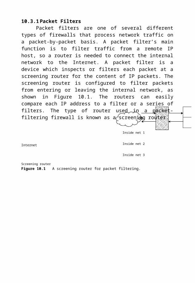
Certificate AuthorityCardholder (consumer) (CA)
Initiate requestInitiate response
CardholderRegistration form requestRegistration form supplyregistration
Certificate requestCertificate return
Purchaserequest
fororder process
(1) Initial request(1) (2) (3) (4) (2) Initial response Cardholder’s
(3) Purchase request bank(4) Purchase response
Purchaseresponse
Issuerfororder process
CARegistration form supply
MerchantRegistration form return
Certificate requestregistrationCertificate return
Payment gateway
PaymentAuthorisation request
Authorisation response Issuer’s responseauthorisation
Capture requestMerchant’sPayment and capture tokencapture financial
Capture response institutionand gateway certificate
MerchantAcquirer
Figure 11.6 Overall picture of payment processing.
It is worth depicting this registration process as shown in Figure 11.7.
2. Registration form process: • The cardholder generates the registration form request.
Initiate request (IRq)
Cardholder Certification(CH) Authority
(CA)
D Kpc CAC Initiate response(x.509) (IRs)(CA’s public key) Ksc
(CA’s privatekey)
CAC MD E IRs
H SHA-1
Verify byEKsc (CAC)traversing H(IRs) = MD:
to the root key Message digest
Compare E
EKsc(MD):
Digital signature
Kpc D EKsc (CAC) EKsc (MD)
(CA’s public key)
IRq : Initiate request Ksc : CA’s private keyIRs : Initiate response Kpc : CA’s public keyCAC : CA certificate (X.509)H : Hash functionH(IRs) = MD : Message digest of the responseEKsc(MD) = EKsc(H(IRS)) : Digital signature
EKsc(CAC) : Digital signature of certificate
Figure 11.7 Registration request/response processes.
• The cardholder encrypts the SET message with a random symmetric key (No. 1). The DES key, along with the cardholder’s account number, is then encrypted with the CA’s public key.
• The cardholder transmits the encrypted registration form request to the CA. • The CA decrypts the symmetric DES key (No. 1) and cardholder’s account num-ber
with the CA’s private key. The CA then decrypts the registration form request using the symmetric DES key (No. 1).
• The CA determines the appropriate registration form and digitally signs it by generating a message digest of the registration form and encrypting it with the CA’s private key.
• The CA sends the registration form and the CA certificate to the cardholder. • The cardholder receives the registration form and verifies the CA certificate by
traversing the trust chain to the root key. • The cardholder verifies the CA’s signature by decrypting it with the CA’s pub-lic key
and comparing the result with a newly generated message digest of the registration form. The cardholder then completes the registration form.
The registration form process is depicted as shown Figure 11.8.
3. Certificate request/response processes: • The cardholder generates the certificate request, including the information entered into
the registration form. • The cardholder creates a message with request, the cardholder’s public key and a
newly generated symmetric key (No. 2), and digitally signs it by generating a message digest of the cardholder’s private key.
• The cardholder encrypts the message with a randomly generated symmetric key (No. 3). This symmetric key, along with the cardholder’s account information, is then encrypted with the CA’s public key.
• The cardholder transmits the encrypted certificated request messages to the CA. • The CA decrypts the No. 3 symmetric key and cardholder’s account information with
the CA’s private key, and then decrypts the certificate request using this symmetric key.
• The CA verifies the cardholder’s signature by decrypting it with the cardholder’s public key and comparing the result with a newly generated message digest of the certificate requested.
• The CA verifies the certificate request using the cardholder’s account information and information from the registration form.
• Upon verification the CA creates the cardholder certificate, digitally signing it with the CA’s private key.
• The CA generates the certificate response and digitally signs it by generating a message digest of the response and encrypting it with the CA’s private key.
• The CA encrypts the certificate response with the No. 2 symmetric key from the cardholder request.
• The CA transmits the certificate response to the cardholder. • The cardholder verifies the certificate by traversing the trust chain to the root key.
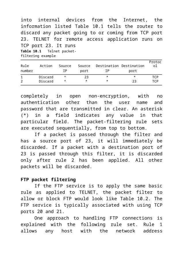
Figure 11.8 Registration form process.• The cardholder decrypts the response using the symmetric key (No. 2) saved from the
cardholder request process. • The cardholder verifies the CA’s signature by decrypting it with the CA’s pub-lic key
and comparing the result with a newly generated message digest of the response. • The cardholder stores the certificate and information from the response for future e-
commerce use.
11.6.2 Merchant RegistrationMerchants must register with a CA before they can receive SET payment
instructions from cardholders. In order to send SET messages to the CA, the merchant must have a copy of the CA’s public key which is provided in the CA certificate. The merchant also needs the registration form from the acquirer. The merchant must identify the acquirer to the CA. The merchant registration process consists of five steps as follows: (1) The merchant requests the registration form; (2) the CA processes this request and sends the registration form; (3) the merchant requests certificates after receiving the registration certificates; (4) the CA creates certificates; (5) the merchant receives certificates. The detailed steps for the merchant registration are described in what follows.
1. Registration form process:The registration process starts when the merchant requests the appropriate registration form.
• The merchant sends the initiate request of the registration form to the CA. To register, the merchant fills out the registration form with information such as the merchant’s name, address and ID.
• The CA receives the initiate request. • The CA selects an appropriate registration form and digitally signs it by gener-ating a
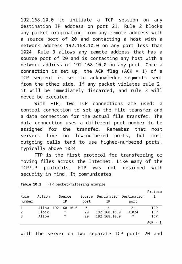
message digest of the registration form and encrypting it with the CA’s private key. • The CA sends the registration form along with the CA certificate to the merchant. • The merchant receives the registration form and verifies the CA certificate by
traversing the trust chain to the root key. • The merchant verifies the CA’s signature by decrypting it with the CA’s public key
and comparing the result with a newly computed message digest of the registration form.
• The merchant creates two public/private-key pairs for use with SET: key encryp-tion and signature.
Thus, the merchant completes the registration form. The merchant takes the regis-tration information (name, address and ID) and combines it with the public key in a registration message. The merchant digitally signs the registration message. Next the merchant’s software generates a random symmetric key. This random key is used to encrypt the message. The key is then encrypted into the digital envelope using the CA’s public key. Finally, the merchant transmits all of these components to the CA.
2. Certificate request/create process:The merchant starts with the certificate request. When the CA receives the merchant’s
request, it decrypts the digital envelope to obtain the symmetric encryption key, which it uses to decrypt the registration request.
• The merchant generates the certificate request. • The merchant creates the message with request and both merchant public keys and
digitally signs it by generating a message digest of the certificate request and encrypting it with the merchant’s private key.
• The merchant encrypts the message with a random symmetric key (No. 1). This symmetric key, along with the merchant’s account data, is then encrypted with the CA’s public key.
• The merchant transmits the encrypted certificate request message to the CA. • The CA decrypts the symmetric key (No. 1) and the merchant’s account data with the
CA’s private key, and then decrypts the message using the symmetric key (No. 1). • The CA verifies the merchant’s signature by decrypting it with the merchant’s public
key and comparing the result with a newly computed message digest of the certificate request.
• The CA confirms the certificate request using the merchant information. • Upon verification, the CA creates the merchant certificate digitally signing the
certificate with the CA’s private key. • The CA generates the certificate response and digitally signs it by generating a
message digest of the response and encrypting it with the CA’s private key. • The CA transmits the certificate response to the merchant. • The merchant receives the certificate response from the CA. The merchant decrypts
the digital envelope to obtain the symmetric key. This key is used to decrypt the registration response containing the certificates.
• The merchant verifies the certificates by traversing the trust chain to the root key. • The merchant verifies the CA’s signature by decrypting it with the CA’s public key
and comparing the result with a newly computed message digest of the certificate response.
• The merchant stores the certificates and information from the response for use in future e-commerce transactions.
11.6.3 Purchase RequestThe purchase request exchange should take place after the cardholder has completed
browsing, selecting and ordering. Before the end of this preliminary phase occurs, the
merchant sends a completed order form to the cardholder (customer). In order to send SET messages to a merchant, the cardholder must have a copy of the certificates of the merchant and the payment gateway. The message from the cardholder indicates which payment card brand will be used for the transaction. The purchase request exchange consists of four messages: initiate request, initiate response, purchase request and purchase response. The detailed discussions that follow describe each step fully.
1. Initiate request: • The cardholder sends the initiate request to the merchant. • The merchant receives the initiate request. • The merchant generates the response and digitally signs it by generating a message
digest of the response and encrypting it with the merchant’s private key. • The merchant sends the response along with the merchant and payment gateway
certificates to the cardholder.
2. Initiate response: • The cardholder receives the initiate response and verifies the certificates by travers-ing
the trust chain to the root key. • The cardholder verifies the merchant’s signature by decrypting it with the mer-chant’s
public key and comparing the result with a newly computed message digest of the response.
• The cardholder creates the order message (OM) using information from the shop-ping phase and payment message (PM). At this step the cardholder completes payment instructions.
3. Purchase request: • The cardholder generates a dual signature for the OM and PM by computing the
message digests of both, concatenating the two digests, computing the message digest of the result and encrypting it using the cardholder’s private key.
• The cardholder generates a random symmetric key (No. 1) and uses it to encrypts the PM. The cardholder then encrypts his or her account number as well as the random symmetric key used to encrypt the PM in a digital envelope using the payment gateway’s key.
• The cardholder transmits the OM and the encrypted PM to the merchant. • The merchant verifies the cardholder certificate by traversing the trust chain to the root
key. • The merchant verifies the cardholder’s dual signature on the OM by decrypting it with
the cardholder’s public key and comparing the result with a newly computed message digest of the concatenation of the message digests of the OM and PM.
• The merchant processes the request, including forwarding the PM to the payment gateway for authorisation.
4. Purchase response: • The merchant creates the purchase response including the merchant signature
certificate and digitally signs it by generating a message digest of the purchase response and encrypting it with the merchant’s private key.
• The merchant transmits the purchase response to the cardholder. • If the transaction was authorised, the merchant fulfils the order to the cardholder. • The cardholder verifies the merchant signature certificate by traversing the trust chain
to the root key. • The cardholder verifies the merchant’s digital signature by decrypting it with the
merchant’s public key and comparing the result with a newly computed message digest of the purchase response.
• The cardholder stores the purchase response.
11.6.4 Payment AuthorisationDuring the processing of an order from a cardholder, the merchant authorises the trans-action. The authorisation request and the cardholder payment instructions are then trans-mitted to the payment gateway.
1. Authorisation request: • The merchant creates the authorisation request. • The merchant digitally signs an authorisation request by generating a message digest
of the authorisation request and encrypting it with the merchant’s private key. • The merchant encrypts the authorisation request using a random symmetric key (No.
2), which in turn is encrypted with the payment gateway public key. • The merchant transmits the encrypted authorisation request and the encrypted PM
from the cardholder purchase request to the payment gateway. • The gateway verifies the merchant certificate by traversing the trust chain to the root
key. • The payment gateway decrypts the digital envelope of the authorisation request to
obtain the symmetric encryption key (No. 2) with the gateway private key. The gateway then decrypts the authorisation request using the symmetric key (No. 2).
• The gateway verifies the merchant’s digital signature by decrypting it with the merchant’s public key and comparing the result with a newly computed message digest of the authorisation request.
• The gateway verifies the cardholder’s certificate by traversing the trust chain to the root key.
• The gateway decrypts the symmetric key (No. 1) and the cardholder account information with the gateway private key. It uses the symmetric key to decrypt the PM.
• The gateway verifies the cardholder’s dual signature on the PM by decrypting it with the cardholder’s public key and comparing the result with a newly computed message digest of the concatenation of the message digest of the OM and the PM.
• The gateway ensures consistency between the merchant’s authorisation request and the cardholder’s PM.
• The gateway sends the authorisation request through a financial network to the cardholder’s financial institution (issuer).
2. Authorisation response: • The gateway creates the authorisation response message and digitally signs it by
generating a message digest of the authorisation response and encrypting it with the gateway’s private key.
• The gateway encrypts the authorisation response with a new randomly generated symmetric key (No. 3). This key is then encrypted with the merchant’s public key.
• The gateway creates the capture token and digitally signs it by generating a mes-sage digest of the capture token and encrypting it with the gateway’s private key.
• The gateway encrypts the capture token with a new symmetric key (No. 4). This key and the cardholder account information are then encrypted with the gateway’s public key.
• The gateway transmits the encrypted authorisation response to the merchant. • The merchant verifies the gateway certificate by traversing the trust chain to the root
key. • The merchant decrypts the symmetric key (No. 3) with the merchant’s pri-vate key
and then decrypts the authorisation response using the symmetric key (No. 3). • The merchant verifies the gateway’s digital signature by decrypting it with the
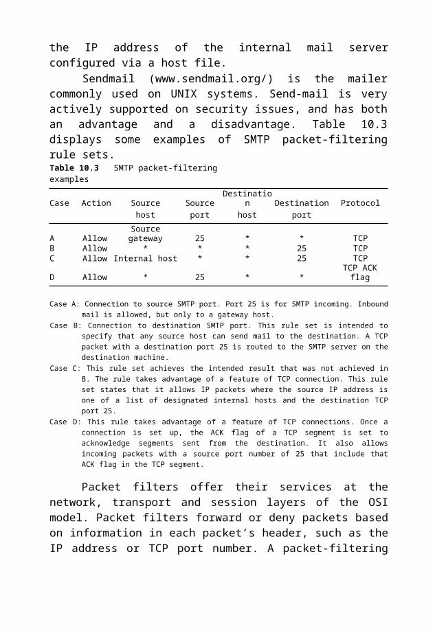
gateway’s public key and comparing the result with a newly computed message digest of the authorisation response.
• The merchant stores the encrypted capture token and envelope for later cap-ture processing.
• The merchant then completes processing of the purchase request and the card-holder’s order by shipping the goods or performing the services indicated in the order.
11.6.5 Payment CaptureAfter completing the processing of an order from a cardholder, the merchant will request payment. The merchant generates and signs a capture request, which includes the final amount of the transaction, the transaction identifier from the OM, and other information about the transaction. A merchant’s payment capture process will be described in detail in the following.
1. Capture request: • The merchant creates the capture request. • The merchant embeds the merchant certificate in the capture request and digitally
signs it by generating a message digest of the capture request and encrypting it with the merchant’s private key.
• The merchant encrypts the capture request with a randomly generated symmetric key (No. 5). This key is then encrypted with the payment gateway’s public key.
• The merchant transmits the encrypted capture request and encrypted capture token previously stored from the authorisation response to the payment gateway.
• The gateway verifies the merchant certificate by traversing the trust chain to the root key.
• The gateway decrypts the symmetric key (No. 5) with the gateway’s private key and then decrypts the capture request using the symmetric key (No. 5).
• The gateway verifies the merchant’s digital signature by decrypting it with the merchant’s public key and comparing the result with a newly computed message digest of the capture request.
• The gateway decrypts the symmetric key (No. 4) with the gateway’s private key and then decrypts the capture token using the symmetric key (No. 4).
• The gateway ensures consistency between the merchant’s capture request and the capture token.
• The gateway sends the capture request through a financial network to the card-holder’s issuer (financial institution).
2. Capture response: • The gateway creates the capture response message, including the gateway signa-ture
certificate, and digitally signs it by generating a message digest of the capture response and encrypting it with the gateway’s private key.
• The gateway encrypts the capture response with a newly generated symmetric key (No. 6). This key is then encrypted with the merchant’s public key.
• The gateway transmits the encrypted capture response to the merchant. • The merchant verifies the gateway certificate by traversing the trust chain to the root
key. • The merchant decrypts the symmetric key (No. 6) with the merchant’s private key and
then decrypts the capture response using the symmetric key (No. 6).
Merchant Payment gateway
Capture request Capture responseH MD(CRq) (CRs)
CRsCRsM’s G’s DES CTcert cert K#4 DESE K#6
DESE
H E EK#6(CRs) KsgK#5 D E
Kpg
Ksg
Kpm
EMD EK#5(CRq) EK#4(CT) E DESD K#5
DK
pg DCRq
DCT
DESK#6 D
Newly generatedK
sm
digital signatureCompare
Gateway digital signature
Kpm : merchant's public keyKsm : merchant's private keyKpg : payment gateway's public keyKsg : payment gateway's private key
Figure 11.9 Payment capture process.
• The merchant verifies the gateway’s digital signature by decrypting it with the gateway’s public key and comparing the result with a newly generated message digest of the capture response.
Figure 11.9 shows an overview of payment capture consisting of the merchant’s capture request and the gateway’s capture response.