Embed Size (px)
Citation preview

ARMY19.1 Small Business Innovation Research (SBIR)
Proposal Submission Instructions
INTRODUCTION
The US Army Research, Development, and Engineering Command (RDECOM) is responsible for execution of the Army SBIR Program. Information on the Army SBIR Program can be found at the following Website: https://www.armysbir.army.mil / .
Broad Agency Announcement (BAA), topic, and general questions regarding the SBIR Program should be addressed according to the DoD Program BAA. For technical questions about the topic during the pre-release period, contact the Topic Authors listed for each topic in the BAA. To obtain answers to technical questions during the formal BAA period, visit https://sbir.defensebusiness.org/. Specific questions pertaining to the Army SBIR Program should be submitted to:
Monroe HardenActing Program Manager, Army SBIR [email protected] US Army Research, Development and Engineering Command (RDECOM)6200 Guardian GatewaySuite 145Aberdeen Proving Ground, MD 21005-1322TEL: 866-570-7247
The Army participates in three DoD SBIR BAAs each year. Proposals not conforming to the terms of this BAA will not be considered. Only Government personnel will evaluate proposals with the exception of technical personnel from Oak Ridge Institute for Science and Education (ORISE), MITRE Corporation, Graham Technologies, LLC., CACI International Inc., Irving Burton Associates, Geneva Foundation, and Henry Jackson Foundation who will provide Advisory and Assistance Services to the Army and technical analysis in the evaluation of proposals submitted against Army topic numbers:
A19-059 “Smartphone Clustering and Data-Partitioning/Recombination Processing Framework” (IrvingBurton Associates, Geneva Foundation and Henry Jackson Foundation)A19-060 “Far Forward Medical Logistics Light Weight Store and Forward Capability” (CACI International Inc.) A19-063 “Heat-Transmitting/Heat-Trapping Lightweight Textile” (ORISE)A19-078 “Data Sharing and Encryption” (Graham Technologies, LLC)A19-079 “Economical, Multi-Use Software-Defined Radio Capability at Ku-Band and Above” (MITRE)
The individuals from Oak Ridge Institute for Science and Education (ORISE), MITRE Corporation, Graham Technologies, LLC, Irving Burton Associates, CACI International Inc., Geneva Foundation, and Henry Jackson Foundation will be authorized access to only those portions of the proposal data and discussions that are necessary to enable them to perform their respective duties. These institutions are expressly prohibited from competing for SBIR awards and from scoring or ranking of proposals or recommending the selection of a source. In accomplishing their duties related to the selection processes, the aforementioned institutions may require access to proprietary information contained in the offerors’ proposals. Therefore, pursuant to FAR 9.505-4, the institutions must execute an agreement that states that they will (1) protect the offerors’ information from unauthorized use or disclosure for as long as it remains proprietary and (2) refrain from using the information for any purpose other than that for which it
ARMY - 1

was furnished. These agreements will remain on file with the Army SBIR program management office at the address above.
PHASE I PROPOSAL SUBMISSION
SBIR Phase I proposals have four Volumes: Proposal Cover Sheet, Technical Volume, Cost Volume and Company Commercialization Report. Please note that the Army will not be accepting a Volume Five (Supporting Documents), nor a Volume Six (Fraud, Waste and Abuse) as noted at the DoD SBIR website. The Technical Volume .pdf document has a 20-page limit including: table of contents, pages intentionally left blank, references, letters of support, appendices, technical portions of subcontract documents (e.g., statements of work and resumes) and any other attachments. Small businesses submitting a Phase I Proposal must use the DoD SBIR electronic proposal submission system (https://sbir.defensebusiness.org/). This site contains step-by-step instructions for the preparation and submission of the Proposal Cover Sheet, the Company Commercialization Report, the Cost Volume, and how to upload the Technical Volume. For general inquiries or problems with proposal electronic submission, contact the DoD SBIR Help Desk at 1-800-348-0787.
The small business will also need to register at the Army SBIR Small Business website: https://portal.armysbir.army.mil/Portal/SmallBusinessPortal/Default.aspx in order to receive information regarding proposal status/debriefings, summary reports, impact/transition stories, and Phase III plans. PLEASE NOTE: If this is your first time submitting an Army SBIR proposal, you will not be able to register your firm at the Army SBIR Small Business website until after all of the proposals have been downloaded and we have transferred your company information to the Army Small Business website. This can take up to one week after the end of the proposal submission period.
Do not include blank pages, duplicate the electronically generated cover pages or put information normally associated with the Technical Volume such as descriptions of capability or intent in other sections of the proposal as these will count toward the 20-page limit.
Only the electronically generated Cover Sheets, Cost Volume and Company Commercialization Report (CCR) are excluded from the 20-page limit. The CCR is generated by the proposal submission website, based on information provided by you through the Company Commercialization Report tool. Army Phase I proposals submitted containing a Technical Volume .pdf document containing over 20 pages will be deemed NON-COMPLIANT and will not be evaluated. It is the responsibility of the Small Business to ensure that once the proposal is submitted and uploaded into the system that the technical volume .pdf document complies with the 20 page limit.
Phase I proposals must describe the "vision" or "end-state" of the research and the most likely strategy or path for transition of the SBIR project from research to an operational capability that satisfies one or more Army operational or technical requirements in a new or existing system, larger research program, or as a stand-alone product or service.
Phase I proposals will be reviewed for overall merit based upon the criteria in Section 6.0 of the DoD Program BAA.
19.1 Phase I Key DatesBAA closes, proposals due 6 Feb 2019, 8:00 pm ET Phase I Evaluations 8 Feb – 11 Mar 2019Phase I Selections Announced 8 May 2019Phase I Award Goal 8 Jul 2019**Subject to the Congressional Budget process
ARMY - 2

PHASE I OPTION MUST BE INCLUDED AS PART OF PHASE I PROPOSAL
The Army implements the use of a Phase I Option that may be exercised to fund interim Phase I activities while a Phase II contract is being negotiated. Only Phase I efforts selected for Phase II awards through the Army’s competitive process will be eligible to have the Phase I Option exercised. The Phase I Option, which must be included as part of the Phase I proposal, should cover activities over a period of up to four months and describe appropriate initial Phase II activities that may lead to the successful demonstration of a product or technology. The Phase I Option must be included within the 20-page limit for the Phase I proposal. Do not include blank pages, duplicate the electronically generated cover pages or put information normally associated with the Technical Volume such as descriptions of capability or intent, in other sections of the proposal as these will count toward the 20 page limit.
PHASE I COST VOLUME
A firm fixed price or cost plus fixed fee Phase I Cost Volume ($162,500 maximum-PLEASE NOTE THAT THE MAXIMUM DOLLAR AMOUNT HAS BEEN INCREASED COMPARED TO PREVIOUS PHASE I’s) must be submitted in detail online. Proposers that participate in this BAA must complete a Phase I Cost Volume not to exceed a maximum dollar amount of $108,000 and six months and a Phase I Option Cost Volume not to exceed a maximum dollar amount of $54,500 and four months (PLEASE NOTE THESE DOLLAR AMOUNTS HAVE BEEN INCREASED COMPARED TO PREVIOUS PHASE I’s) . The Phase I and Phase I Option costs must be shown separately but may be presented side-by-side in a single Cost Volume. The Cost Volume DOES NOT count toward the 20-page Phase I proposal limitation when submitted via the submission site’s on-line form. When submitting the Cost Volume, complete the Cost Volume form on the DoD Submission site, versus submitting it within the body of the uploaded proposal.
PHASE II PROPOSAL SUBMISSION
Commencing with Phase II’s resulting from a 13.1 Phase I, invitations are no longer required. Small businesses submitting a Phase II Proposal must use the DoD SBIR electronic proposal submission system (https://sbir.defensebusiness.org/). This site contains step-by-step instructions for the preparation and submission of the Proposal Cover Sheet, the Company Commercialization Report, the Cost Volume, and how to upload the Technical Volume. For general inquiries or problems with proposal electronic submission, contact the DoD Help Desk at 1-800-348-0787.
Army SBIR has four cycles in each FY for Phase II submission. A single Phase II proposal can be submitted by a Phase I awardee within one, and only one, of four submission cycles and must be submitted between 4 to 17 months after the Phase I contract award date. Any proposals that are not submitted within these four submission cycles and before 4 months or after 17 months from the contract award date will not be evaluated. The submission window opens at 0001hrs (12:01 AM) eastern time on the first day and closes at 2359 hrs (11:59 PM) eastern time on the last day. Any subsequent Phase II proposal (i.e., a second Phase II subsequent to the initial Phase II effort) shall be initiated by the Government Technical Point of Contact for the initial Phase II effort and must be approved by Army SBIR PM in advance.
The four Phase II submission cycles following the announcement of selections for the 19.1 BAA are:
2019(d) 1 Aug 2019 – 3 Sep 20192020(a) 16 Oct – 15 Nov 20202020(b) 2 Mar – 1 Apr 20202020(c) 15 Jun – 15 Jul 2020
ARMY - 3

For other submission cycle see the schedule below, and always check with the Army SBIR Program Managers office helpdesk for the exact dates.
SUBMISSION CYCLES TIMEFRAMECycle One 30 calendar days starting on or about 15 October*Cycle Two 30 calendar days starting on or about 1 March*Cycle Three 30 calendar days starting on or about 15 June*Cycle Four 30 calendar days starting on or about 1 August*
*Submission cycles will open on the date listed unless it falls on a weekend or a Federal Holiday. In those cases, it will open on the next available business day.
Army SBIR Phase II Proposals have four Volumes: Proposal Cover Sheet, Technical Volume, Cost Volume and Company Commercialization Report. The Technical Volume .pdf document has a 38-page limit including: table of contents, pages intentionally left blank, references, letters of support, appendices, technical portions of subcontract documents (e.g., statements of work and resumes), data assertions and any attachments. Do not include blank pages, duplicate the electronically generated cover pages or put information normally associated with the Technical Volume in other sections of the proposal as these will count toward the 38 page limit. As with Phase I proposals, it is the proposing firm’s responsibility to verify that the Technical Volume .pdf document does not exceed the page limit after upload to the DoD SBIR/STTR Submission site by clicking on the “Verify Technical Volume” icon.
Only the electronically generated Cover Sheet, Cost Volume and Company Commercialization Report (CCR) are excluded from the 38-page Technical Volume. The CCR is generated by the proposal submission website, based on information provided by you through the Company Commercialization Report tool.
Army Phase II Proposals submitted containing a Technical Volume .pdf document over 38 pages will be deemed NON-COMPLIANT and will not be evaluated.
Army Phase II Cost Volumes must contain a budget for the entire 24 month Phase II period not to exceed the maximum dollar amount of $1,075,000 (PLEASE NOTE THAT THIS DOLLAR AMOUNT HAS BEEN INCREASED COMPARED TO PREVIOUS PHASE II’s). During contract negotiation, the contracting officer may require a Cost Volume for a base year and an option year. The proposal cost volumes must be submitted using the Cost Volume format (accessible electronically on the DoD submission site), and may be presented side-by-side on a single Cost Volume Sheet. The total proposed amount should be indicated on the Proposal Cover Sheet as the Proposed Cost. Phase II projects will be evaluated after the base year prior to extending funding for the option year.
Small businesses submitting a proposal are required to develop and submit a technology transition and commercialization plan describing feasible approaches for transitioning and/or commercializing the developed technology in their Phase II proposal.
DoD is not obligated to make any awards under Phase I, II, or III. For specifics regarding the evaluation and award of Phase I or II contracts, please read the DoD Program BAA very carefully. Phase II proposals will be reviewed for overall merit based upon the criteria in Section 8.0 of the BAA.
BIO HAZARD MATERIAL AND RESEARCH INVOLVING ANIMAL OR HUMAN SUBJECTS
ARMY - 4

Any proposal involving the use of Bio Hazard Materials must identify in the Technical Volume whether the contractor has been certified by the Government to perform Bio Level - I, II or III work.
Companies should plan carefully for research involving animal or human subjects, or requiring access to government resources of any kind. Animal or human research must be based on formal protocols that are reviewed and approved both locally and through the Army's committee process. Resources such as equipment, reagents, samples, data, facilities, troops or recruits, and so forth, must all be arranged carefully. The few months available for a Phase I effort may preclude plans including these elements, unless coordinated before a contract is awarded.
FOREIGN NATIONALS
If the offeror proposes to use a foreign national(s) [any person who is NOT a citizen or national of the United States, a lawful permanent resident, or a protected individual as defined by 8 U.S.C. 1324b (a) (3) – refer to Section 3.5 of this BAA for definitions of “lawful permanent resident” and “protected individual”] as key personnel, they must be clearly identified. For foreign nationals, you must provide country of origin, the type of visa or work permit under which they are performing and an explanation of their anticipated level of involvement on this project. Please ensure no Privacy Act information is included in this submittal.
OZONE CHEMICALS
Class 1 Ozone Depleting Chemicals/Ozone Depleting Substances are prohibited and will not be allowed for use in this procurement without prior Government approval.
CONTRACTOR MANPOWER REPORTING APPLICATION (CMRA)
The Contractor Manpower Reporting Application (CMRA) is a Department of Defense Business Initiative Council (BIC) sponsored program to obtain better visibility of the contractor service workforce. This reporting requirement applies to all Army SBIR contracts.
Offerors are instructed to include an estimate for the cost of complying with CMRA as part of the Cost Volume for Phase I ($108,000 maximum), Phase I Option ($54,500 maximum), and Phase II ($1,075,000 maximum), under “CMRA Compliance” in Other Direct Costs. This is an estimated total cost (if any) that would be incurred to comply with the CMRA requirement. Only proposals that receive an award will be required to deliver CMRA reporting, i.e. if the proposal is selected and an award is made, the contract will include a deliverable for CMRA.
To date, there has been a wide range of estimated costs for CMRA. While most final negotiated costs have been minimal, there appears to be some higher cost estimates that can often be attributed to misunderstanding the requirement. The SBIR Program desires for the Government to pay a fair and reasonable price. This technical analysis is intended to help determine this fair and reasonable price for CMRA as it applies to SBIR contracts.
The Office of the Assistant Secretary of the Army (Manpower & Reserve Affairs) operates and maintains the secure CMRA System. The CMRA Web site is located here: https://www.ecmra.mil/.
The CMRA requirement consists of the following items, which are located within the contract document, the contractor's existing cost accounting system (i.e. estimated direct labor hours, estimated direct labor dollars), or obtained from the contracting officer representative:
(1) Contract number, including task and delivery order number;
ARMY - 5

(2) Contractor name, address, phone number, e-mail address, identity of contractor employee entering data;(3) Estimated direct labor hours (including sub-contractors);(4) Estimated direct labor dollars paid this reporting period (including sub-contractors);(5) Predominant Federal Service Code (FSC) reflecting services provided by contractor (and separate predominant FSC for each sub-contractor if different);(6) Organizational title associated with the Unit Identification Code (UIC) for the Army Requiring Activity (The Army Requiring Activity is responsible for providing the contractor with its UIC for the purposes of reporting this information);(7) Locations where contractor and sub-contractors perform the work (specified by zip code in the United States and nearest city, country, when in an overseas location, using standardized nomenclature provided on Web site);
The reporting period will be the period of performance not to exceed 12 months ending September 30 of each government fiscal year and must be reported by 31 October of each calendar year.
According to the required CMRA contract language, the contractor may use a direct XML data transfer to the Contractor Manpower Reporting System database server or fill in the fields on the Government Web site. The CMRA Web site also has a no-cost CMRA XML Converter Tool.
Given the small size of our SBIR contracts and companies, it is our opinion that the modification of contractor payroll systems for automatic XML data transfer is not in the best interest of the Government. CMRA is an annual reporting requirement that can be achieved through multiple means to include manual entry, MS Excel spreadsheet development, or use of the free Government XML converter tool. The annual reporting should take less than a few hours annually by an administrative level employee.
Depending on labor rates, we would expect the total annual cost for SBIR companies to not exceed $500.00 annually, or to be included in overhead rates.
DISCRETIONARY TECHNICAL ASSISTANCE
In accordance with section 9(q) of the Small Business Act (15 U.S.C. 638(q)), the Army will provide technical assistance services to small businesses engaged in SBIR projects through a network of scientists and engineers engaged in a wide range of technologies. The objective of this effort is to increase Army SBIR technology transition and commercialization success thereby accelerating the fielding of capabilities to Soldiers and to benefit the nation through stimulated technological innovation, improved manufacturing capability, and increased competition, productivity, and economic growth.
The Army has stationed nine Technical Assistance Advocates (TAAs) across the Army to provide technical assistance to small businesses that have Phase I and Phase II projects with the participating organizations within their regions.
For more information go to: https://www.armysbir.army.mil, then click the “SBIR” tab, and thenclick on Transition Assistance/Technical Assistance.
As noted in Section 4.22 of this BAA, firms may request technical assistance from sources other than those provided by the Army. All such requests must be made in accordance with the instructions in Section 4.22. It should also be noted that if approved for discretionary technical assistance from an outside source, the firm will not be eligible for the Army’s Technical Assistance Advocate support. All details of the DTA agency and what services they will provide must be listed in the technical proposal under “consultants”. The request for DTA must include details on what qualifies the DTA firm to provide the services that you are requesting, the firm name, a point of contact for the firm, and a web site
ARMY - 6

for the firm. List all services that the firm will provide and why they are uniquely qualified to provide these services. The award of DTA funds is not automatic and must be approved by the Army SBIR Program Manager.
COMMERCIALIZATION READINESS PROGRAM (CRP)
The objective of the CRP effort is to increase Army SBIR technology transition and commercialization success and accelerate the fielding of capabilities to Soldiers. The CRP: 1) assesses and identifies SBIR projects and companies with high transition potential that meet high priority requirements; 2) matches SBIR companies to customers and facilitates collaboration; 3) facilitates detailed technology transition plans and agreements; 4) makes recommendations for additional funding for select SBIR projects that meet the criteria identified above; and 5) tracks metrics and measures results for the SBIR projects within the CRP.
Based on its assessment of the SBIR project’s potential for transition as described above, the Army utilizes a CRP investment fund of SBIR dollars targeted to enhance ongoing Phase II activities with expanded research, development, test and evaluation to accelerate transition and commercialization. The CRP investment fund must be expended according to all applicable SBIR policy on existing Phase II availability of matching funds, proposed transition strategies, and individual contracting arrangements.
NON-PROPRIETARY SUMMARY REPORTS
All award winners must submit a non-proprietary summary report at the end of their Phase I project and any subsequent Phase II project. The summary report is unclassified, non-sensitive and non-proprietary and should include:A summation of Phase I resultsA description of the technology being developedThe anticipated DoD and/or non-DoD customerThe plan to transition the SBIR developed technology to the customerThe anticipated applications/benefits for government and/or private sector useAn image depicting the developed technology
The non-proprietary summary report should not exceed 700 words, and is intended for public viewing on the Army SBIR/STTR Small Business area. This summary report is in addition to the required final technical report and should require minimal work because most of this information is required in the final technical report. The summary report shall be submitted in accordance with the format and instructions posted within the Army SBIR Small Business Portal at:https://portal.armysbir.army.mil/Portal/SmallBusinessPortal/Default.aspx and is due within 30 days of the contract end date.
ARMY - 7

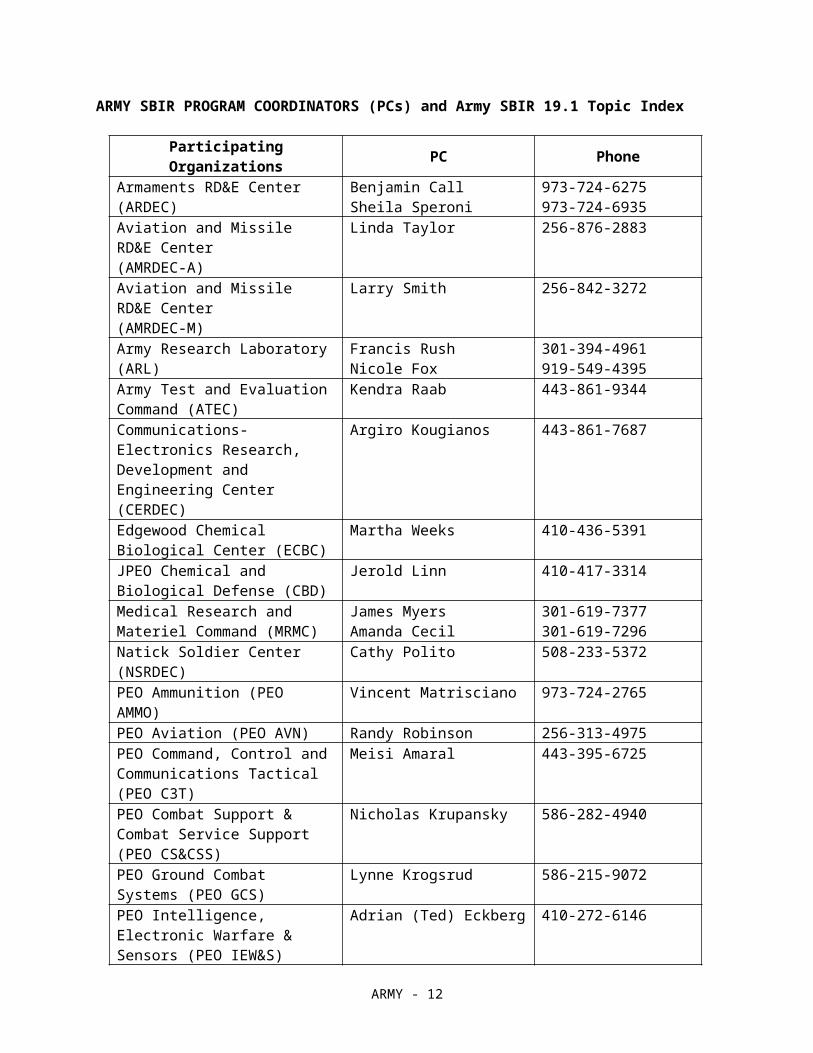
ARMY SBIR PROGRAM COORDINATORS (PCs) and Army SBIR 19.1 Topic Index
Participating Organizations PC Phone
Armaments RD&E Center (ARDEC) Benjamin CallSheila Speroni
973-724-6275 973-724-6935
Aviation and Missile RD&E Center(AMRDEC-A)
Linda Taylor 256-876-2883
Aviation and Missile RD&E Center(AMRDEC-M)
Larry Smith 256-842-3272
Army Research Laboratory (ARL) Francis RushNicole Fox
301-394-4961919-549-4395
Army Test and Evaluation Command (ATEC)
Kendra Raab 443-861-9344
Communications-Electronics Research, Development and Engineering Center (CERDEC)
Argiro Kougianos 443-861-7687
Edgewood Chemical Biological Center (ECBC)
Martha Weeks 410-436-5391
JPEO Chemical and Biological Defense (CBD)
Jerold Linn 410-417-3314
Medical Research and Materiel Command (MRMC)
James MyersAmanda Cecil
301-619-7377301-619-7296
Natick Soldier Center (NSRDEC) Cathy Polito 508-233-5372PEO Ammunition (PEO AMMO) Vincent Matrisciano 973-724-2765PEO Aviation (PEO AVN) Randy Robinson 256-313-4975PEO Command, Control and Communications Tactical (PEO C3T)
Meisi Amaral 443-395-6725
PEO Combat Support & Combat Service Support (PEO CS&CSS)
Nicholas Krupansky 586-282-4940
PEO Ground Combat Systems (PEO GCS)
Lynne Krogsrud 586-215-9072
PEO Intelligence, Electronic Warfare & Sensors (PEO IEW&S)
Adrian (Ted) Eckberg 410-272-6146
PEO Missiles and Space (PEO M&S)
David Tritt 256-313-3431
PEO Simulation, Training, and Instrumentation (PEO STRI)
Robert Forbis 407-384-3884
Space and Missile Defense Command (SMDC)
Gary Mayes 256-955-4904
Tank Automotive RD&E Center (TARDEC)
George Pappageorge 586-282-7541
ARMY SUBMISSION OF FINAL TECHNICAL REPORTS
A final technical report is required for each project. Per DFARS clause 252.235-7011(http://www.acq.osd.mil/dpap/dars/dfars/html/current/252235.htm#252.235-7011), each contractor shall (a) Submit two copies of the approved scientific or technical report delivered under the contract to the
ARMY - 8

Defense Technical Information Center, Attn: DTIC-O, 8725 John J. Kingman Road, Fort Belvoir, VA 22060-6218; (b) Include a completed Standard Form 298, Report Documentation Page, with each copy of the report; and (c) For submission of reports in other than paper copy, contact the Defense Technical Information Center or follow the instructions at http://www.dtic.mil.
DEPARTMENT OF THE ARMY PROPOSAL CHECKLIST
This is a Checklist of Army Requirements for your proposal. Please review the checklist to ensure that your proposal meets the Army SBIR requirements. You must also meet the general DoD requirements specified in the BAA. Failure to meet these requirements will result in your proposal not being evaluated or considered for award. Do not include this checklist with your proposal.
1. The proposal addresses a Phase I effort (up to $108,000 with up to a six-month duration) AND an optional effort (up to $54,500 for an up to four-month period to provide interim Phase II funding).
2. The proposal is limited to only ONE Army BAA topic.
3. The technical content of the proposal, including the Option, includes the items identified in Section 5.4 of the BAA.
4. SBIR Phase I Proposals have four (4) sections: Proposal Cover Sheet, Technical Volume, Cost Volume and Company Commercialization Report. The Technical Volume .pdf document has a 20-page limit including, but not limited to: table of contents, pages intentionally left blank, references, letters of support, appendices, technical portions of subcontract documents [e.g., statements of work and resumes] and all attachments). However, offerors are instructed to NOT leave blank pages, duplicate the electronically generated cover pages or put information normally associated with the Technical Volume in other sections of the proposal submission as THESE WILL COUNT AGAINST THE 20-PAGE LIMIT. Any information that details work involved that should be in the technical volume but is inserted into other sections of the proposal will count against the page count. ONLY the electronically generated Cover Sheet, Cost Volume and Company Commercialization Report (CCR) are excluded from the Technical Volume .pdf 20-page limit. As instructed in Section 5.4.e of the DoD Program BAA, the CCR is generated by the submission website, based on information provided by you through the “Company Commercialization Report” tool. Army Phase I proposals submitted with a Technical Volume .pdf document of over 20-pages will be deemed NON-COMPLIANT and will not be evaluated.
5. The Cost Volume has been completed and submitted for both the Phase I and Phase I Option and the costs are shown separately. The Army requires that small businesses complete the Cost Volume form on the DoD Submission site, versus submitting within the body of the uploaded proposal. The total cost should match the amount on the cover pages.
6. Requirement for Army Accounting for Contract Services, otherwise known as CMRA reporting is included in the Cost Volume (offerors are instructed to include an estimate for the cost of complying with CMRA).
7. If applicable, the Bio Hazard Material level has been identified in the Technical Volume.
8. If applicable, plan for research involving animal or human subjects, or requiring access to government resources of any kind.
9. The Phase I Proposal describes the "vision" or "end-state" of the research and the most likely strategy or path for transition of the SBIR project from research to an operational capability that satisfies
ARMY - 9
one or more Army operational or technical requirements in a new or existing system, larger research program, or as a stand-alone product or service.
10. If applicable, Foreign Nationals are to be identified in the proposal.
ARMY - 10

ARMY SBIR 19.1 Topic Index
A19-001 Advanced Comprehensive Analysis Tool for Emerging Vertical Lift ConfigurationsA19-002 DEVELOP SAND-PLUGGING RESISTANT METALLIC COMBUSTOR LINERSA19-003 Low Cost Fabrication Techniques for Propulsion StructuresA19-004 Low-cost, Heat-resistant Composites for Large-caliber Armament ApplicationsA19-005 (This topic has been deleted from this Announcement on 12/17/19)A19-006 Futures Emergency Management through Artificial IntelligenceA19-007 Non-Line of Sight Directional Control TechnologyA19-008 Robust Wideband Full Duplex RadiosA19-009 New Concept for a Low Distortion, High-Power, High-Efficiency mm-Wave RF Power
Amplifier CircuitA19-010 Solid Oxide Fuel Cell (SOFC) Power SystemA19-011 Ultra-narrow linewidth, high power semiconductor laserA19-012 Interconnected Networks and Dense Urban ResilienceA19-013 Flexible interface for implementing trainee state-driven customizations of virtual training
environmentsA19-014 Computational models and wearable sensors for real-time assessments of Soldiers’
performance in complex tasksA19-015 Narrowband High Reflector Microstructure for 1030-1070 nm Continuous WaveA19-016 Extended Near Infrared Focal Plane Array development for Versatile Imaging Systems
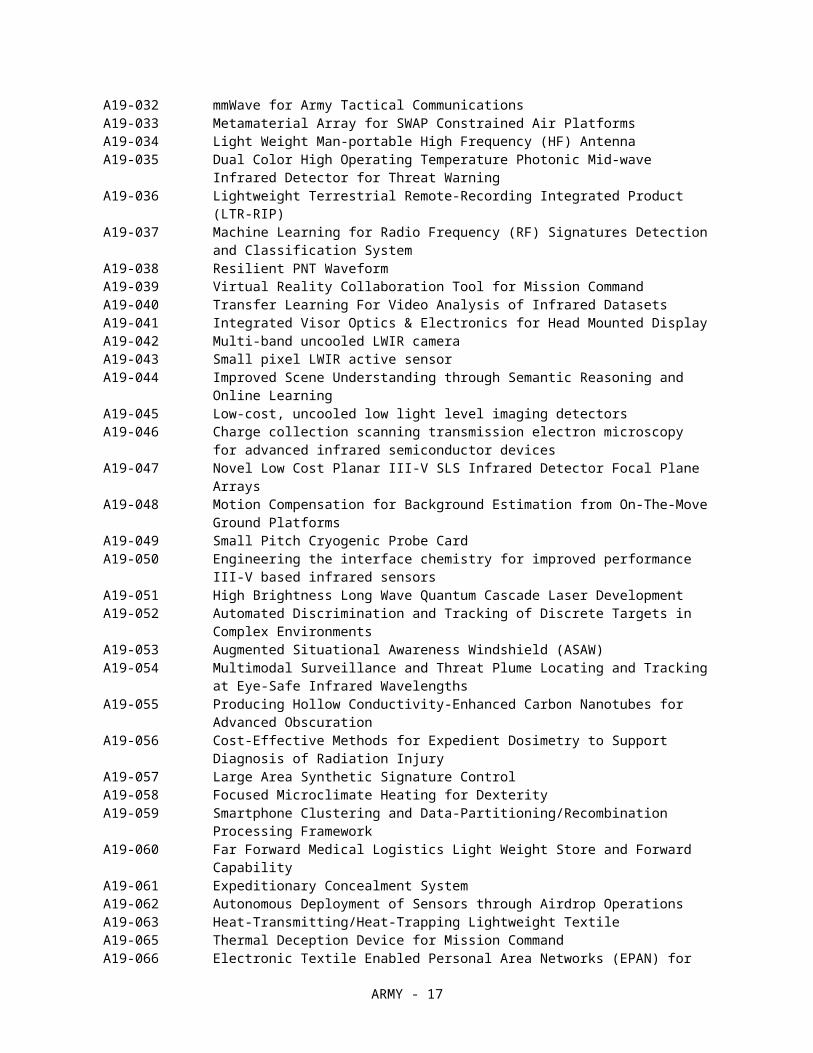
ApplicationsA19-017 Increased Operability and Operating Temperature of HgCdTe MWIR and LWIR FPAsA19-018 (0001) AlGaN Templates with Low Threading Dislocation DensityA19-019 Small Rotor Acoustic Signature ReductionA19-020 Modeling and Control Methods for Future Vertical Lift Rotorcraft Fatigue ReductionA19-021 Modeling of Microstructural Irregularities in Additively Manufactured MaterialsA19-022 Device for hydrogen on demand from aluminum alloy and water reactionA19-023 (This topic has been deleted from this Announcement on 2/6/19)A19-024 Slant Path Optical Turbulence and Atmospheric CharacterizationA19-025 Ultra-High Accuracy RF Ranging and Time/Frequency TransferA19-026 Multi-beam Wideband SATCOM AntennaA19-027 DC/AC Distribution Box for Extended Tactical Power Architectures (CERDEC 4)A19-028 Machine Learning Dataset Auto Generator (ML-DAG)A19-029 Wideband, Programmable, Multifunctional Transmitter/Receiver (TRX) ModuleA19-030 Modular, Fuel Flexible Power SourceA19-031 Provenance using Blockchain on Disconnected NetworksA19-032 mmWave for Army Tactical CommunicationsA19-033 Metamaterial Array for SWAP Constrained Air PlatformsA19-034 Light Weight Man-portable High Frequency (HF) AntennaA19-035 Dual Color High Operating Temperature Photonic Mid-wave Infrared Detector for Threat
WarningA19-036 Lightweight Terrestrial Remote-Recording Integrated Product (LTR-RIP)A19-037 Machine Learning for Radio Frequency (RF) Signatures Detection and Classification SystemA19-038 Resilient PNT WaveformA19-039 Virtual Reality Collaboration Tool for Mission CommandA19-040 Transfer Learning For Video Analysis of Infrared DatasetsA19-041 Integrated Visor Optics & Electronics for Head Mounted DisplayA19-042 Multi-band uncooled LWIR cameraA19-043 Small pixel LWIR active sensorA19-044 Improved Scene Understanding through Semantic Reasoning and Online LearningA19-045 Low-cost, uncooled low light level imaging detectorsA19-046 Charge collection scanning transmission electron microscopy for advanced infrared
semiconductor devicesA19-047 Novel Low Cost Planar III-V SLS Infrared Detector Focal Plane Arrays
ARMY - 11
A19-048 Motion Compensation for Background Estimation from On-The-Move Ground PlatformsA19-049 Small Pitch Cryogenic Probe CardA19-050 Engineering the interface chemistry for improved performance III-V based infrared sensorsA19-051 High Brightness Long Wave Quantum Cascade Laser DevelopmentA19-052 Automated Discrimination and Tracking of Discrete Targets in Complex EnvironmentsA19-053 Augmented Situational Awareness Windshield (ASAW)A19-054 Multimodal Surveillance and Threat Plume Locating and Tracking at Eye-Safe Infrared
WavelengthsA19-055 Producing Hollow Conductivity-Enhanced Carbon Nanotubes for Advanced ObscurationA19-056 Cost-Effective Methods for Expedient Dosimetry to Support Diagnosis of Radiation InjuryA19-057 Large Area Synthetic Signature ControlA19-058 Focused Microclimate Heating for DexterityA19-059 Smartphone Clustering and Data-Partitioning/Recombination Processing FrameworkA19-060 Far Forward Medical Logistics Light Weight Store and Forward CapabilityA19-061 Expeditionary Concealment SystemA19-062 Autonomous Deployment of Sensors through Airdrop OperationsA19-063 Heat-Transmitting/Heat-Trapping Lightweight TextileA19-065 Thermal Deception Device for Mission CommandA19-066 Electronic Textile Enabled Personal Area Networks (EPAN) for Ground and Air SoldiersA19-069 Manufacturing Production of Electronic Textiles and Connectors for Wearable Heating
DevicesA19-070 Innovative Primer Design for Large Caliber AmmunitionA19-071 Weather Situational Awareness in the CockpitA19-072 Micro Identification Friend or Foe (IFF) TransponderA19-073 Secure Avionics Mobile and Windshield Display TechnologiesA19-074 Safe High Performing Rechargeable Military BatteryA19-076 Expeditionary Additive Manufacturing (AM): Metallic Based SystemsA19-077 Effective Heat Exchanger PerformanceA19-078 Data Sharing and EncryptionA19-079 Economical, Multi-Use Software-Defined Radio Capability at Ku-Band and AboveA19-080 Cyber Security Tool Kits for Engineers and SoldiersA19-081 Non-Explosive Non Nuclear Electro-Magnetic Pulse (EMP) Power SupplyA19-082 Energy harvesting solutions for tracking flight times in aviation and missile structuresA19-083 Automated Cyber Opposition ForcesA19-084 Trust and Situational Awareness in Augmented Reality Soldier TrainingA19-085 High Power High Efficiency Single Mode Diode EmitterA19-086 High Dynamic Range Camera for High Energy Laser Fine TrackingA19-087 Adaptive Optics System for a High Energy Laser Weapon SystemA19-088 Lightweight Optical Components for High Energy Laser SystemA19-089 Advanced Diesel Engine High-Pressure Fuel Injection PumpA19-090 Battery Cycle Life & Performance Optimization for Small and Medium-Sized Robotic
PlatformsA19-091 Electric Coolant Pump for High-Temperature Power Generation Cooling ApplicationsA19-092 Aviation Filtration Technology for the Replacement of Filter MonitorsA19-093 Wide Band Gap High Current Solid State Circuit Protection DeviceA19-094 600VDC to 208VAC 3-Phase Bi-Directional Power InverterA19-095 Multi-Axis Energy Attenuation Seat SystemA19-096 JP-8 Conversion Kit for Small Spark Ignition Gasoline EnginesA19-097 Deep Learning Architecture for a Wide Variety of SensorsA19-098 Combat Vehicle Programs: Product Development (PD) Resilience through Set-Based Design
ApplicationA19-099 Photovoltaic Powered Low Power Dehumidification Systems for Individual Combat Vehicle
InteriorsA19-100 Identification Friend or Foe (IFF) Panel with Dynamic Contrast at Long Wave Infrared
(LWIR) Wavelengths
ARMY - 12

ARMY SBIR 19.1 Topic Descriptions
A19-001 TITLE: Advanced Comprehensive Analysis Tool for Emerging Vertical Lift Configurations
TECHNOLOGY AREA(S): Air Platform
The technology within this topic is restricted under the International Traffic in Arms Regulation (ITAR), which controls the export and import of defense-related material and services. Offerors must disclose any proposed use of foreign nationals, their country of origin, and what tasks each would accomplish in the statement of work in accordance with section 5.4.c.(8) of the Announcement.
OBJECTIVE: Develop an advanced analysis tool that can effectively support next generation vertical lift manned/unmanned rotorcraft design and development. The advanced analysis tool should significantly expand existing rotorcraft comprehensive analysis codes with innovative modeling and analysis capabilities to address non-conventional vertical lift configurations such as electric vertical takeoff and landing (eVTOL) with numerous rotors, fans, propellers, and lifting surfaces. The enhanced modeling and analysis methods should be suited for integration into industry standard comprehensive analysis and simulation programs.
DESCRIPTION: Recent emerging electric and hybrid-electric propulsion technologies showed the feasibility for new forms of civil and military operations in the future. These disruptive technologies have the potential to reshape manned, optionally manned, and un-manned air vehicles. The simplicity of electric propulsion offers the potential to greatly reduce acquisition and operating costs by doing away with the complexity of turbine engines and shaft interconnect drive trains. Distributed electric propulsion offers design flexibility for aerodynamics configurations that offer new opportunities to enhance the aerodynamic performance and efficiency of vertical lift aircraft. As a result, many proposed concepts utilize multiple rotors, fans, propellers, wings, etc. However, existing comprehensive rotorcraft analysis tools have been developed for conventional single main rotor or tandem rotor helicopter and tiltrotor vehicles and, therefore, their capabilities for the accurate and efficient analyses of multi rotor/propeller configurations are somewhat limited.
Some of the modeling and analysis challenges are 1) aerodynamic interaction between multiple lifting/propulsive devices (e.g., may involve 8-20 rotors/propellers and each rotor/propeller has 2-6 blades), 2) complicated load paths of each lifting and propulsive device, 3) aeroelastic effects between the lifting/propulsive devices and supporting structures, 4) rotor/airframe coupling with electrical motor dynamics, and 5) performing trim solutions for aircraft with multiple redundant options for trim control variables.
To address these challenges, current comprehensive analysis capabilities need to be significantly expanded and enhanced. Aerodynamic modeling of low aspect ratio, non-planar lifting surfaces and propeller ducts will be needed such as lifting surface or panel methods. The modeling and analysis to be developed should be capable of simulating mutual interference among the various lifting/propulsive devices such as rotors, propellers, fans, wings, control surfaces, etc. This will require wake models that can accommodate lifting surfaces and aero-bodies immersed within the wake. Innovative methods are required in order to efficiently simulate the mutual interference effects such that they can be used to support extensive design iterations and engineering analyses with required accuracy.
An accurate structural loads analysis capability which can capture details of complex load paths is required to handle arbitrary non-conventional configurations. This capability is also required for accurate prediction of local deformation which may be very important for sensor/motor placements. The developed method should also be easily applicable for high-fidelity computational structural dynamics (CSD) and computational fluid dynamics (CFD) rotorcraft modeling and analysis that aeroelastically couple rotor system CFD aerodynamics to flexible blade CSD structural models.
Accurate prediction of rotorcraft aeroelastic and aeromechanical stability is essential for the successful design of all types of rotorcraft. The challenges related to non-conventional configurations with multiple rotors/propellers/wings is that the model can involve thousands or more degrees of freedom. Advanced methodology is required for efficient analysis to support design and development of new configurations. A novel method is sought to visualize mode shapes of complex configurations to help engineers quickly identify critical modes. Efficient Floquet method with practical mode identification would also be useful.
ARMY - 13

Electrically driven motor propulsion is one of the unique aspects of emerging vertical lift configurations. The modeling of electric motor propulsion system dynamics, high power electric motor controllers, motor and battery heat reduction, and their coupling with rotor/airframe/control needs to be addressed. The electrical motor system allows control of the rotor speed for operation. The new analysis methods should be able to efficiently handle the rotor RPM control in addition to the conventional rotor blade pitch control.
PHASE I: Develop innovative methodologies that can analyze interference effects, coupled dynamics, loads and aeroelastic stability of non-conventional vertical lift configurations with multiple rotors/propellers/wings and demonstrate efficiency and accuracy of the proposed methods for notional configurations. Prototype mode visualization tool and demonstrate its efficiency and ease of use.
PHASE II: Complete the development of the proposed modeling methods and visualization tool and integrate them into rotorcraft comprehensive analysis tools. Perform verification and validation of the new modeling capabilities at both the component level and the integrated vehicle level for multiple realistic configurations.
PHASE III DUAL USE APPLICATIONS: Finalize the advanced rotorcraft comprehensive analysis tool with efficient and accurate design, modeling, and analysis capability of new vertical takeoff and landing aircraft with numerous rotors/propellers. Finalize visualization tool to mode shapes of complex configurations to help engineers quickly identify critical modes. Develop comprehensive documentation, detailed tutorials, and demonstration/validation problem materials for self-learning. The validated tool should be able to effectively support the Army Tactical UAS. Potential customers include industry, commercial ventures, DoD, as well as academia.
REFERENCES:1. Saberi, H. A., Hasbun, M., Hong, J., Yeo, H., and Ormiston, R. A., “RCAS Overview of Capabilities, Validations, and Applications to Rotorcraft Problems,” American Helicopter Society 71st Annual Forum Proceedings, Virginia Beach, VA, May 5-7, 2015.
2. Johnson, W., “Technology Drivers in the Development of CAMRAD II,” American Helicopter Society Aeromechanics Specialist Meeting, San Francisco, CA, January 19-21, 1994.
3. Whittle, R., “Air Mobility Bonanza Beckons Electric VTOL Developers,” Vertiflite, March-April, 2017.
4. Swartz, K. I., “Charging Forward New eVTOL Concepts Advance,” Vertiflite, July-August, 2017.
KEYWORDS: Rotorcraft, eVTOL, Multi rotor/propeller configurations, Comprehensive analysis
A19-002 TITLE: DEVELOP SAND-PLUGGING RESISTANT METALLIC COMBUSTOR LINERS
TECHNOLOGY AREA(S): Air Platform
The technology within this topic is restricted under the International Traffic in Arms Regulation (ITAR), which controls the export and import of defense-related material and services. Offerors must disclose any proposed use of foreign nationals, their country of origin, and what tasks each would accomplish in the statement of work in accordance with section 5.4.c.(8) of the Announcement.
OBJECTIVE: Develop Sand-plugging Resistant Combustor Liners.
DESCRIPTION: DESCRIPTION: Modern gas turbine engines operate at high firing temperatures and pressures, requiring advanced cooling for combustors in order to meet adequate useful field life. Turbine engine combustor liners are thin-walled chambers that encase the combustion process. They use small angled holes (i.e. effusion) to enable gas, which is cooler and at higher pressure than the internal liner gas (where combustion occurs), to be passed through the liner to provide effective film cooling of the liner wall. Additionally, thermal barrier coatings are
ARMY - 14

deposited on the hot side of the liner to minimize liner temperatures and increase life. These small angled holes, which are typically in the range of 0.015-0.20 in. diameter, are prone to deposition by ultra-fine dust (<10 micrometers) ingested during operation in regions with elevated levels of dust or sand. Deposition is the buildup of the ultra-fine dust inside the liner cooling passages and typically can cause on the order of 25% blockage between overhaul periods. This deposition is detrimental to film cooling effectiveness, which results in progressively higher liner temperatures with reduced component life and premature engine removal. Another compounding factor is that elevated turbine inlet temperature in advanced designs can exceed 3000°F which tends to increase the plugging rate, making advanced Future Vertical Lift (FVL) engines more susceptible than current production or legacy engines.The Objective of the topic is to develop combustor liner designs that resist deposition/plugging of their cooling passages. The major program metric is to demonstrate advanced liner designs that produce 1/5 the blockage of conventional liner designs. This can be validated initially through modeling and then demonstrated in Phase II via back-to-back rig testing of conventional liner designs and the new advanced design. The liner must also demonstrate the capability to maintain cooling effectiveness of conventional designs for combustion temperatures of up to 3000°F. The advanced design must also be shown to be compatible with thermal barrier coatings.
PHASE I: The proposed SBIR program effort would include the following: 1) through modeling and conceptual analysis, develop advanced liner geometry that results in 1/5 the blockage of conventional liner designs from sand and dust deposition, 2) perform analysis to demonstrate that geometry does not negatively impact film cooling effectiveness or component life and that it is compatible with thermal barrier coatings and 3) produce several coupons with a representative pattern for manufacturing demonstration.
PHASE II: It would be desired that the offeror work with an engine Original Equipment Manufacturer (OEM) to fabricate coupons/components of the advanced liner design including the thermal barrier coating. Assessment by coupon/component validation testing at relevant gas turbine engine combustor conditions with fine sand (AFRL 02) introduced into the inlet would be essential in order to validate the reduced blockage due to sand and ability to maintain a high cooling effectiveness.
PHASE III DUAL USE APPLICATIONS: If phase II provides the expected level of sand-blockage reduction with no impact on film effectiveness, the optimized process shall be applied to a combustor and the combustor shall be evaluated in a cyclic endurance test in a test engine to advance the technology to TRL 6-7, validate materials data and clear it for production introduction.
DUAL USE APPLICATIONS: The resulting technology will enable improved combustor component life and performance, and reduce the CMAS degradation of thermal barrier coatings. The developed cooling technology would have both military and commercial application.
REFERENCES:1. W. S. Walsh, and K. A. Thole, Chris Joe “EFFECTS OF SAND INGESTION ON THE BLOCKAGE OF FILM-COOLING HOLES”, GT2006-90067 Proceedings of ASME Turbo Expo 2006, May8-11, 2006.
2. Peter Forsyth, David R H Gillespie, Matthew McGilvray “DEVELOPMENT AND APPLICATIONS OF A COUPLED PARTICLE DEPOSITION
3. Powder Technology INC. (2018). AFRL 02 Test Dust. http://www.powdertechnologyinc.com/product/afrl-02-test-dust/
4. N. D. Cardwell, K. A. Thole, S. W. Burd “INVESTIGATION OF SAND BLOCKING WITHIN IMPINGEMENT AND FILM-COOLING HOLES”, The American Society of Mechanical Engineers, Published January 21, 2010
KEYWORDS: KEYWORDS: Gas Turbine Engine, Film Cooling effectiveness, Combustors, Impingement, Dust & Sand Plugging
ARMY - 15

A19-003 TITLE: Low Cost Fabrication Techniques for Propulsion Structures
TECHNOLOGY AREA(S): Materials/Processes
The technology within this topic is restricted under the International Traffic in Arms Regulation (ITAR), which controls the export and import of defense-related material and services. Offerors must disclose any proposed use of foreign nationals, their country of origin, and what tasks each would accomplish in the statement of work in accordance with section 5.4.c.(8) of the Announcement.
OBJECTIVE: Fiber reinforced polymer matrix composite materials offer many advantages in terms of structural performance for missile applications; however, fabrication can still be very costly depending on the design. The objective is thus to develop low cost fabrication techniques for cylindrical structural geometries that are optimized with respect to cost and in-plane tensile performance.
DESCRIPTION: Fiber reinforced polymer matrix composite materials continue to rapidly improve in terms of structural performance. In missile structures, composites are advantageous due to their specific strength and specific stiffness characteristics. Current state of the art missile airframe and solid rocket motor case structures are fabricated using filament winding techniques. This process has many advantages, however, the tooling can be costly, and depending on the design and its structural features, the labor can be significant. The objective is to develop novel fabrication techniques that would allow reduction in cost for cylindrical structural geometries. The goal will be to develop a process capable of producing continuous fiber, intermediate modulus carbon reinforced epoxy cylindrical structural shapes at a cost reduction of 20% relative to a comparable filament wound structure. Considering that cost reduction often impacts structural performance, the goal will be to meet this cost goal without decreasing axial and transverse tensile and compressive strength by more than 10%. For cost and strength comparison purposes, the baseline cylinder design would have a strength of 200,000 psi in the axial direction and a strength of 200,000 psi in the hoop direction. The baseline cylinder design would have a thickness of 0.1 inches. By advancing structural technology applicable to propulsion system design, this effort is an enabler for extended range for systems in the Army Modernization Priorities for long range precision fires.
PHASE I: Perform analytical trade studies and subscale fabrication demonstrations of fabrication techniques that reduce the cost of cylindrical composite structures. The trade studies and feasibility demonstrations will focus on techniques that can be scaled to larger cylindrical geometries in excess of 7” diameter. The objective of this phase is to acquire sufficient test data and cost information using small diameter cylinders to demonstrate feasibility.
PHASE II: Develop and demonstrate advanced fabrication techniques that are able to produce cylindrical geometries representative of missile airframes, solid rocket motors, and missile launch tubes. The objective is to demonstrate these on structural geometries in excess of 7” in diameter, and nominally, 10” in diameter. This phase should demonstrate that the proposed structure can be fabricated with similar quality characteristics to typical filament wound structures in terms of fiber volume fraction and void content. The technique shall be capable of delivering mechanical properties within 10% of an analogous filament wound cylindrical structure using similar fiber reinforcement and similar material orientations. The material properties of interest are elastic stiffness, hoop and axial tension, and hoop and axial compression. The technique shall be capable of delivering structures with a glass transition temperature in excess of 350 °F. The phase II effort shall demonstrate that these properties can be achieved while reducing the cost by 20% relative to the cost of the analogous filament wound structure.
PHASE III DUAL USE APPLICATIONS: Weight reduction is of great importance in many missile structural applications. The ability to produce low cost cylindrical geometries with structural performance equivalent to that of filament wound structures would be advantageous to many Army systems. This technology can be used across a number of applications where weight reduction is important. This is considered pervasive technology and can be applicable to future weight reduction efforts for multiple Army systems including Javelin, JAGM, and TOW. It has the potential to find uses in both military and commercial applications. An example would be to advance a fabrication technique that can be used to produce missile airframe structures at a reduced cost.
REFERENCES:
ARMY - 16
1. Yurko, A. A. and Esslinger, J. R., “Affordable High Performance Composite Case Rocket Motor Manufacturing,” 41st American Institute of Aeronautics and Astronautics(AIAA)/American Society of Mechanical Engineers (ASME)/Society of Automotive Engineers (SAE)/American Society for Engineering Education (ASEE) Joint Propulsion Conference and Exhibit, 2005.
2. Strong, A. B. Fundamentals of Composites Manufacturing: Materials, Methods and Applications, Society of Manufacturing Engineers, 2008.
3. Peters, S. Composite Filament Winding, ASM International, 2011.
4. Encyclopedia of Polymer Science and Technology, 3rd edition, Wiley, 2007.
KEYWORDS: Fiber Reinforced Composites, Low Cost Fabrication, Filament Winding
A19-004 TITLE: Low-cost, Heat-resistant Composites for Large-caliber Armament Applications
TECHNOLOGY AREA(S): Materials/Processes
The technology within this topic is restricted under the International Traffic in Arms Regulation (ITAR), which controls the export and import of defense-related material and services. Offerors must disclose any proposed use of foreign nationals, their country of origin, and what tasks each would accomplish in the statement of work in accordance with section 5.4.c.(8) of the Announcement.
OBJECTIVE: To develop a low-cost organic matrix composite system with high heat resistance and a low-temperature production process to produce gun barrels in support of the Army’s Long Range Precision Fires and Next Generation Combat Vehicle priorities.
DESCRIPTION: To address the Army’s Long Range Precision Fires and Next Generation Combat Vehicle priorities, the Army requires lightweight materials that can operate across the entire spectrum of armament temperatures. Armament systems must operate in ambient temperatures ranging from arctic conditions to desert environments. In a terms of operating conditions while firing, a tank cannon can exceed 400°F, a howitzer 700°F, and a mortar nearly 1000°F. Composites are favored for these applications in the interest of reducing the weight of increasingly long gun tubes on extended range cannons. For combat vehicles, a lighter tube allows for faster aiming and smaller vehicle drive trains.
In addition to operating across this temperature range, the materials must be readily adhered to a traditional metallic substrate and must overcome any coefficient of thermal expansion mismatch to avoid delamination of the barrel. The end state of this effort is a lightweight material solution to address the entire spectrum of armament needs for both direct and indirect fires. This goal must be achieved at a substantially lower cost and with a simpler production process than existing high-use temperature materials like preceramic polymers, ceramic matrix composites, and metal matrix composites.
PHASE I: Develop a composite material system that demonstrates low cost, low processing temperature and high-use temperature. The system should be compatible with existing intermediate modulus carbon fiber such as IM7. Demonstrate its capabilities by producing mechanical test results of fiber reinforced composites across the entire temperature range of interest. At a minimum longitudinal tensile strength and modulus (ASTM D3039 - Standard Test Method for Tensile Properties of Polymer Matrix Composite Materials) tests should be used to demonstrate properties. If a novel material that is not a polymer matrix composite is developed, then the appropriate test standard may be substituted.
The use-temperature must range from -57 °C (-70 °F) to at least 426 °C (800 °F), preferably 538 °C (1000 °F). The material should be physically and environmentally stable across the entire temperature range. The goal is no more than 20% property loss at 426 °C (800 °F), and 50% loss at 538 °C (1000 °F).
ARMY - 17
The processing procedure should be such that it can be applied over a steel substrate without experiencing coefficient of thermal expansion (CTE) issues. This could be an low temperature cure such that the CTE difference is not an issue or a series or cure steps that lock in the composite shape at a low temperature or another mechanism.
Cost of the system should be same or lower than standard temperature thermoset materials with carbon fiber reinforcement such as IM7/8552 or IM7/APC-2.
The material deliverable shall be 25 lbs of developed material in a form that can be processed on existing filament winding equipment.
PHASE II: Refine the material system and produce the selected material using a process representative of plant-scale production manufacturing and conduct the following tests to demonstrate conformance of the material to the topic requirements:
ASTM D3039 (Standard Test Method for Tensile Properties of Polymer Matrix Composite Materials), D3410 (Standard Test Method for Compressive Properties of Polymer Matrix Composite Materials with Unsupported Gage Section by Shear Loading), D2344 (standard Test Method for Short-Beam Strength of Polymer Matrix Composite Materials and Their Laminates), and either D3518 (Standard Test Method for In-Plane Shear Response of Polymer Matrix Composite Materials by Tensile Test of a +/- 45° Laminate) or D5379 (Standard Test Method for Shear Properties of Composite Materials by the V-Notched Beam Method).
If a novel material that is not a polymer matrix composite is developed, then appropriate test standards may be substituted.
Property goals at room temperature in the fiber direction shall be a tensile strength of 200 ksi, a tensile modulus of 25 Msi, a compressive strength of 100 ksi, and a compressive modulus of 20 Msi. The interlaminar shear strength shall be equal to or greater than 9 ksi and any deviation from this value shall be reported and a plan to achieve 9 ksi shall be described. Shear modulus and strength, along with transverse properties, shall be measured as well. At 426 °C (800 °F), properties in all directions shall not decrease by more than 20%. At 538 °C (1000 °F), properties in all directions shall not decrease by more than 50%.
Cost of the system should be same or lower than standard temperature thermoset materials with carbon fiber reinforcement such as IM7/8552 or IM7/APC-2.
The material deliverable shall be an steel cylinder overwrapped with the material system. The cylinder shall have at least a 100mm (3.93 in) bore with wall of at least 6.35 mm (0.25 in) wall thickness. If requested a standard steel test cylinder can be provided. This cylinder will demonstrate that any coefficient of thermal expansion mismatch (CTE) between the steel substrate and the composite can be dealt with during the manufacturing process.
Additionally 25 lbs of the final material in a form suitable for filament winding shall be provided. Preferred form is prepreg (1/8" slit tape or towpreg).
PHASE III DUAL USE APPLICATIONS: In collaboration with the prime contractor and Benet Labs, apply a wrap to a complete gun tube for live fire testing in an operational environment. Explore automotive, down-well piping, and manufacturing technology applications for the material. Adapt the low-cost manufacturing process to material applications with less stringent temperature requirements.
REFERENCES:1. J. B. Root and A. G. Littlefield, Minimizing Rail Deflections in an EM Railgun, November 2006. http://handle.dtic.mil/100.2/ADA481582
2. L. Burton, R. Carter, V. Champagne, R. Emerson, M.l Audino, and E. Troiano, Army Targets Age Old Problems with New Gun Barrel Materials, AMPTIAC Quarterly, v8n4, 2004. http://ammtiac.alionscience.com/pdf/AMPQ8_4ART08.pdf
ARMY - 18
3. A. Littlefield and E. Hyland, Prestressed Carbon Fiber Composite Overwrapped Gun Tube, November 2006. http://handle.dtic.mil/100.2/ADA481065
4. J. S. Montgomery and R. L. Ellis, Large Caliber Gun Tube Materials Systems Design, 10th U.S. Army Gun Dynamics Symposium Proceedings, Austin, TX, April 2002. http://handle.dtic.mil/100.2/ADP012479
5. U.S. Army Materiel Command, ""Research and Development of Materiel, Engineering Design Handbook, Gun Series, Gun Tubes,"" AMCP 706-252, Washington DC (1964). http://handle.dtic.mil/100.2/AD830297
6. Office of the Secretary of Defense (OSD) Manufacturing Technology Program, Manufacturing Readiness Level (MRL) Deskbook, Version 2.0, May 2011. http://www.dodmrl.com/MRL_Deskbook_V2.pdf
KEYWORDS: Advanced composites, High Temperature composites, low cost composites
A19-005 (This topic has been deleted from this Announcement)
A19-006 TITLE: Futures Emergency Management through Artificial Intelligence
TECHNOLOGY AREA(S): Information Systems
The technology within this topic is restricted under the International Traffic in Arms Regulation (ITAR), which controls the export and import of defense-related material and services. Offerors must disclose any proposed use of foreign nationals, their country of origin, and what tasks each would accomplish in the statement of work in accordance with section 5.4.c.(8) of the Announcement.
OBJECTIVE: Research and develop in Artificial Intelligence (AI) application for Emergency Management (EM) procedures to meet the ARMY's priorities of C3I and Long Range Precision Fires priorities which is supported by "The Installations of the Future" vision by utilizing the multitude of correlated and uncorrelated data sources currently available, to include; social media and extremist forums, as well as criminal, government and medical databases, as a decision aid in the identification, prevention and response to subversive incidents.
DESCRIPTION: As the Army Emergency Management (EM) Leader, researching and developing performance enhancements to Installation technologies and tactics, techniques, and procedures across the DoD, ARDEC strives to continually advance knowledge and expertise to optimize processes to ensure mission readiness and installation preparedness across the Joint community. Installation Emergency Management aligns to the Army Modernization Network/C3I priority. The Acting Assistant Secretary of the Army for Installations, Energy and Environment, Mr. J. Randall Robinson's vision and future focus on "Installations of the Future" includes integrating Resources, Communities, Infrastructure, Services, Soldiers and Ranges and Land to improve force protection, individual and unit readiness across the ARMY. This Small Business Innovation Research Phase I project will develop knowledge in AI computing algorithms and methods for the purpose of identification, prevention, response, and recovery of human-initiated emergency incidents as an enhancement to the ARDEC developed Physical Security Integration Framework (PSIF). Currently the PSIF Enterprise Architecture allows for the integrated use and management of Installation processes, technologies, personnel, and business practices in the areas of Daily Operations, Pre-planned Events and No-notice Incidents. An understanding of emerging AI techniques, as well as the applicability of various data sources to key personnel during an emergency event will be refined and better understood to optimize Installation Emergency Management functions. The research conducted in Phase I will inform the development of an integrated application to the existing PSIF framework that would be able to support machine learning of key words and relationships and threat data analytics that when correlated would present a trigger or alert for a security officials to review or act upon. There is no consolidated criminal investigation database to allow for the search or analysis of criminal behavior that could affect the ability to detect a potential threat. Therefore, a feasibility study of related, existing databases would be conducted to determine relevant data and potential access and privacy concerns for each considered data source. An investigation of data mining, machine learning, and synthetic perception will be conducted to further understand the architecture of an EM-driven AI software system. Evaluation of content to detect emerging events and threats as they're developing, and methods of pushing alerts to users based on user-
ARMY - 19

defined areas and topics of interest would also be included in Phase I. This research and application can ultimately provide Installation EM personnel and law enforcement with predictive trends, which would feed decision-making during all phases of an emergency.
PHASE I: Phase I will develop knowledge in AI computing algorithms and methods for the purpose of identification, prevention, response and recovery of human-initiated emergency incidents. The research conducted in Phase I will inform the development of a platform that would be able to recognize key words and relationships, that when correlated would present a trigger or alert for a security officials to review as a decision aid.
PHASE II: Phase II results in prototype software leveraging AI and multiple data sources, to aid in decision making for the EM community.
PHASE III DUAL USE APPLICATIONS: Phase III results in an accredited production software system, leveraging AI and multiple data sources, to be deployed to approved personnel within the EM community of the Army.
REFERENCES:1. Bayesian Logic Programs for Plan Recognition and Machine Reading - http://www.cs.utexas.edu/users/ml/papers/raghavan-dissertation.pdf
2. Automatic Generation of Issue Maps: Structured, Interactive Outputs for Complex Information Needs - http://reports-archive.adm.cs.cmu.edu/anon/2012/CMU-CS-12-140.pdf
3. ENGINEERING CROWDSOURCED STREAM PROCESSING SYSTEMS https://arxiv.org/pdf/1310.5463.pdf
4. Coordinating Human and Machine Intelligence to Classify Microblog Communications in Crises http://chato.cl//papers/iscram_2014_coordinating_human_machine_intelligence_crises.pdf
5. AIDR: Artificial Intelligence for Disaster Response http://chato.cl/papers/demo_2014_aidr_artificial_intelligence_disaster_response.pdf
6. Extracting Information Nuggets from Disaster Related Messages in Social Media http://chato.cl/papers/imran_elbassuoni_castillo_diaz_meier_2013_extracting_information_nuggets_disasters.pdf
KEYWORDS: artificial intelligence, emergency management, research, computer learning, data mining, data correlation, database, event correlation, public safety, security threat, emergency prevention, emergency response
A19-007 TITLE: Non-Line of Sight Directional Control Technology
TECHNOLOGY AREA(S): Electronics
OBJECTIVE: To develop a non-line of sight directional control technology/device for canines that does not compromise secured tactical positions of US Army SOF forces in a variety of operational and environmental conditions. Providing a mounted visual and audio feedback sensor system from the canine to a canine handler.
DESCRIPTION: Multi-purpose canines (MPCs) attached to Army Special Operational Forces (ARSOF) units play pivotal roles in small unit tactics as a force multiplier. ARSOF canine handler’s inability to effectively communicate with MPC’s in non-line of sight (LOS) scenarios limit the ARSOF Soldier maneuverability, survivability, lethality and unit tactical advantage. Current techniques for off-leash directional control require red, visible lasers to “push” MPCs to a specific locations within the canine handler’s line of sight. Line of sight direction control greatly limits the operational utility and activities of MPCs in combat scenarios, clandestine operations, surveillance and remote detection events. Red visible lasers are detectable by the enemy as they refract light off particulates in the air (water vapor, dust, smoke) and reflect off surfaces, especially during nighttime operations potentially compromising the ARSOF mission. The proposed technology should augment canine vision for the purpose of directional control
ARMY - 20
throughout non-line of sight operational scenarios while maintaining a covert profile during a variety of environmental and clandestine operations. Basic research in canine cognition and performance has the potential when coupled with advances in augmented vision to provide a new capability for the Soldier. This effort will combine research in vision, augmented reality, and neuroscience for the Soldier canine system.
PHASE I: The Phase I will conduct a design analysis which identifies the technical feasibility of augmenting canine vision and integration of sensory inputs including, but not limited to, canine physiological measurements, accelerometers, audio/video inputs, or environmental conditions. The design analysis should detail how it will meet the requirements for 1) less than 50 millisecond latency for video and audio information relay between the MPC and handler/command unit, 2) demonstration of a system that enable non-line of sight communication and directional control of an MPC at a minimum of 100 meters with specificity, 3) development of a form factor such that the device will not impede the vision or normal functions of the MPC, and, 4) provide audio and video transmission through three concrete walls with no loss of signal integrity. This Phase I deliverable should include a working proof of concept that demonstrates these key technologies in a controlled environment.
PHASE II: Develop and deliver five functioning prototypes for Government testing and evaluation. Prototypes shall; 1) relay visual information from the MPC to the canine handler via a wrist, forearm or chest mounted display or be viewed in a command operations center with less than 50 millisecond latency, 2) relay and transmit audio commands to/from the canine handler with less than 50 millisecond latency, 3) enable a handler to stand at distances up to 200M, outside line of sight, to direct an MPC around obstructions, buildings in dense urban and rural environments, 4) enable non-LOS directional control with target specificity, 5) the device should be streamlined to the canine, be able to withstand direct impact strikes from objects and obstacles a MPC may encounter during operations, and avoid entanglements on obstacles (i.e. tree branches, shrubs, fencing, furniture, etc.), 6) the device will be hardened to operate in a variety of environments (heat, cold, rain, dry, etc.), and 7) the device should be made such that it does not impair the natural movement of the canine. Depending on the complexity of the device, Phase II should also include training support by the vendor with canines to ensure proper demonstration of the device.
PHASE III DUAL USE APPLICATIONS: Deployment of a fully functional canine non-LOS directional device has application a variety of customers including; the Department of Defense, Department of Justice, Department of Homeland Security, Customs and Border Patrol, Marshal Service, Secret Service, FBI and any other agencies that maintain canine teams including rural search and rescue and traditional law enforcement. The Phase III transition plan should include a market analysis defining and understanding of the requirements for the above customers, identifying licensing and manufacturing partners to support commercialization of the designed technology.
REFERENCES:1. North Carolina State University - https://news.ncsu.edu/2014/10/bozkurt-dogs-2014/
2. Taking off the Leash, expanding K-9 capabilities. http://k2si.com/wp-content/uploads/k2off-leash-k9copaprl2013.pdf
3. “ARSOF 2022: U.S. ARMY SPECIAL OPERATIONS COMMAND” http://www.soc.mil/Assorted%20Pages/ARSOF2022_vFINAL.pdf
KEYWORDS: directional control, non-line of sight, augmented reality, off leash control
A19-008 TITLE: Robust Wideband Full Duplex Radios
TECHNOLOGY AREA(S): Electronics
OBJECTIVE: To develop and demonstrate a wideband in-band full duplex radio that can transmit and receive at the same frequency at the same time by canceling self-interference to effectively double throughput.
ARMY - 21

DESCRIPTION: The ability to simultaneously transmit and receive (STAR or full duplex) in the same frequency would significantly reduce the RF spectrum congestion, allowing for significantly more network throughput. Such radios can enable active jamming of adversaries, can save energy, double the bandwidth, and improve security. True in-band full duplex radios has been investigated for decades, but recent advances have shown that it may be possible, using digital and analog signal processing, new devices, multiple antenna techniques [1,2,3,4]. Although preliminary work on full duplex radios is promising, their scope and applicability is still limited. Most existing work in the domain are limited in bandwidth and/or frequency. Other potential benefits to full duplex are creating a secure channel by using one direction as a jammer and measuring channel state information by assuming reciprocity.The primary challenge is to cancel the transmitted signal in the receive change with high enough fidelity that the receive signal can be detected which is many orders of magnitude smaller than the transmit signal (often, more than 100 dB). This is made even more difficult due to electronics nonlinearities. Even antenna coupling and local reflections (which will be time varying if moving) will cause difficulties, due to the required cancellation.Many of the recent solutions include modifications to the RF front end. Such modifications include using high resolution (18-bit or higher) Analog to Digital Converter (ADC), ultra-low-noise amplifier, RF circulators or other isolation circuits, or other expensive, high-performance components in the transceiver chains. Unique antenna designs and directional antennas have also been utilized to increase isolation for full duplex. These modifications increase the cost and potentially the size, weight, and power (SWAP). In addition, modifications to current designs can cause either incompatibility with current hardware or require expensive retrofitting of existing equipment. Therefore the overall impact of radio modifications should be minimized.
The required self-interference cancellation will depend on application and the derived link budget. Link budgets should be developed to justify the cancellation level and overall system design. For this solicitation, a goal is set of 110 dB cancellation in order to maximize potential applications.
There is not a specific radio platform targeted, but the design should minimize impact of modifications to a typical radio with respect to SWAP, cost, and hardware modifications that cause backwards compatibility issues. Bandwidth will be application dependent, but 20MHz. is suggested benchmark and to maximize throughput with a goal of at least 5 bits per second per Hz. each direction.
Manpack radio may be too challenging for full duplex, since the position and orientation of the antenna(s) can change very quickly, small UAV or UGV platforms should be considered.
PHASE I: Characterize the hardware and physical layer architecture required to achieve wideband cancellation (over 110dB cancellation) to enable true full duplex communication. Analyze the software architecture (MAC and higher layer) required to maximally exploit a full duplex physical layer.
If possible, demonstrate a single narrowband prototype (vs. OFDM) of the interference alignment as a proof-of-concept and measure the cancellation capabilities and measure transmitter receiver isolation. A more modest goal of 60dB is suggested for this demonstration.
The design goals are very aggressive, so offeror may have to make trade-off of performance goals, based on technology utilized and potential applications.
Develop potential military and civilian applications based on the performance analysis of proposed architecture. Within this analysis, link budgets, taking explicitly into account the self-inference rejection, will be key to understanding performance of the proposed system(s). This analysis will drive phase II refinements as well as phase III proposals.
PHASE II: Refine the analysis performed in Phase 1 to develop a software-defined radio (SDR) based prototype of true full duplex radios operating over a 20MHz band operating in the 2.4 GHz ISM band. Build and demonstrate this capability. Measure and document performance measures including both isolation and throughput.There will be implications for full duplex on at least the MAC layer and possibly higher. If not already considered, the modifications of MAC and network layers should be analyzed and implemented in the final demonstration.
PHASE III DUAL USE APPLICATIONS: Refine and improve the prototype developed in Phase 2 towards DoD and commercial applications. Develop integrated FPGA-based full duplex radios that withstands stress-tests in a
ARMY - 22
static outdoor environment by the customer. Deliver a mature PHY along with an optimized MAC protocol for full duplex radios.
Specific commercialization strategies are flexible, but could include licensing of the algorithms / software / FPGA firmware, developing and marketing ASICs that implement the algorithms, or full hardware radio hardware incorporating developed algorithms.
Transition applications include vehicle to vehicle communications (both civilian and military), fixed to mobile, and fixed to fixed wireless links.
REFERENCES:1. D. Bharadia, E. McMilin, and S. Katti, “Full duplex radios,” ACM SIGCOMM Computer Communication Review, vol. 43, no. 4, pp. 375–386, 2013
2. . Korpi, T. Riihonen, V. Syrjala, L. Anttila, M. Valkama, and R. Wichman, “Full-Duplex Transceiver System Calculations: Analysis of ADC and Linearity Challenges,” IEEE Transactions on Wireless Communications, vol. 13, no. 7, pp. 3821–3836, Jul. 2014.
3. M. Duarte and A. Sabharwal, “Full-duplex wireless communications using off-the-shelf radios: Feasibility and first results,” in Signals, Systems and Computers (ASILOMAR), 2010 Conference Record of the Forty Fourth Asilomar Conference on, 2010, pp. 1558–15
4. M. Jain et al., “Practical, Real-time, Full Duplex Wireless,” in Proceedings of the 17th Annual International Conference on Mobile Computing and Networking, New York, NY, USA, 2011, pp. 301–312.
KEYWORDS: Full Duplex communications, Simultaneous Transmit and Receive (STAR), Wireless Communications
A19-009 TITLE: New Concept for a Low Distortion, High-Power, High-Efficiency mm-Wave RF Power Amplifier Circuit
TECHNOLOGY AREA(S): Electronics
OBJECTIVE: To develop a novel low distortion, high power, high efficiency, mm-wave RF transmitter power amplifier circuit.
DESCRIPTION: Very efficient amplifier circuits are based on switched mode amplifier designs such as class C, class E or class F amplifiers. The amplifier circuits and their associated mixers are highly non-linear, requiring extensive compensation circuitry. This is particularly a problem with broadband power amplifiers, in which the different frequencies can mix non-linearly to produce excessive intermodulation distortion. As a result, and also because of stability concerns, broad band power amplifiers operating above about 40 GHz generally operate in class A mode, reducing their maximum efficiency. Recent research has demonstrated the possibility that the intermodulation distortion in the amplifier / mixer circuit can be substantially reduced by dividing the frequency band to be amplified into sub-bands, sampling the sub-bands in time, amplifying the sub-band samples separately in time, and recombining the sub-bands in a passive analog reconstituting filter (ref. 1). As a result, there is a smaller range of frequencies at any time being amplified and therefore less intermodulation produced. This has been demonstrated for a wideband signal consisting of pure sine waves evenly spaced in frequency. What has not been demonstrated is the reduction in intermodulation if the wideband signal is divided into frequency sub-bands with more complex waveforms. It is not clear what the tradeoff would be with regard to the sampling time for each frequency sub-band and the number of sub-bands in the wideband signal. The goal of this SBIR topic is to demonstrate feasibility and practicality of power amplifier designs based on this concept. A new low distortion, high power, highly efficient, broadband RF power amplifier circuit concept for mm-wave frequencies should be developed, demonstrated at militarily and commercially relevant frequencies, and the tradeoffs between power, efficiency, the number of sub-bands, intermodulation distortion, and circuit complexity and cost should be
ARMY - 23
quantitatively determined.
A number of commercial and military radios and radars operate at or near 27 GHz with applications including point-to-point communications links, satellite communications, and target acquisition. Currently there are applications for point-to-point communications systems at 80 GHz. New 5G commercial communications applications are expected in these frequency ranges. It is expected that highly efficient, highly linear, high power amplifiers will also be of strong interest to the electronic warfare (EW) community.
This is an Army problem because Army field units are limited in their mobility by the size and weight of the weapons, munitions, and electronics they must carry and by the availability of power and energy. This is especially true for Army aviation and even more so for UAV systems. The power amplifier subsystem is one of the largest and heaviest of the electronics components. Because the amplifier operating at high powers dissipates a large amount of heat, which must be cooled and dissipated, an improvement in efficiency by a factor of 2 results roughly in a corresponding factor of 3 improvement in the overall size and weight of the component, in addition to the reduction in “wall plug” power.
PHASE I: Develop circuit concepts for high efficiency, high power, high bandwidth amplifiers operating at 27 GHz and at 80 GHz, and incorporate the concepts into transmitter front end designs. The concepts should be based on dividing the frequency band into sub-bands, amplifying the sub-bands separately in time, and recombining the sub-bands in a passive analog reconstituting filter. The amplifier circuit (including filter) should have an efficiency greater than 85% and a minimum gain of 10 dB, with an input power of 0.1 milliwatt (-10 dBm) for a QPSK waveform with 0.1% bandwidth (at least 44 Mb/s). Incorporate the amplifier circuit into a mm-wave front end design, making maximum use of digital circuitry (examples of digital circuit approaches to front end design are included in refs. 2 and 3) and of off-the-shelf components. Develop a circuit model with realistic parameters and quantitatively determine design tradeoffs, particularly with respect to power, efficiency, the number of sub-bands, intermodulation distortion, and circuit complexity and cost. Determine distortion and phase noise. Analyze the circuit concept using digital communication theory to determine if information is being lost in the digital compression of the sub-bands. Provide quantitative detail to support a development decision. Develop a detailed preliminary commercialization plan based on a specific product or products and identifying potential commercial partners. Phase I deliverables include the transmitter designs, commercialization plan, and a report detailing the design trade-offs, parameter computation, simulations, model, and feasibility and practicality analysis. Alternative circuit architectures may be examined.
PHASE II: Develop the breadboard and prototype transmitter circuits for the 27 GHz implementation. Experimentally verify design characteristics and parameters. The prototype transmitter should be suitable for application in a satellite communications, point-to-point, or 5G system. Before finalizing the design, explore with potential commercial partners the suitability of the design for application. By theoretical computations and/or simulation explore optimum modulation waveforms. Demonstrate laboratory or breadboard 80 GHz implementation. Using modeling, simulation, and analysis explore feasibility of the circuit concept for higher powers (potentially for EW applications including using tube amplifiers), higher frequencies (up to 200 GHz), and other waveforms (including 256 QAM and frequency hopping). Final design must be scalable to very high powers (MW’s) using tube amplifiers. Develop a packaging plan and manufacturing plan for the final product. Develop a detailed and specific commercialization plan and initiate discussions with potential partners. Explore transitions with DoD laboratories and program offices. Identify military programs for application. Phase II deliverables are the breadboard and prototype of the 27 GHz power amplifier circuit (a power amplifier circuit in the associated mm-wave front end), a report containing experimental detail and results, reports containing the feasibility analyses, 80 GHz feasibility analysis and experiments, and packaging, manufacturing, and commercialization plans.
PHASE III DUAL USE APPLICATIONS: Finalize agreements with commercialization and transition partners. Transition the technology to industry for commercial and military applications. Potential applications will include high efficiency, highly linear power amplifiers in current military point-to-point high data rate communications systems, commercial 5G network systems operating at E-band (70-90 GHz), commercial and military satellite communications systems, and high power electronic (EW) warfare jamming systems. Successful implementation of this technology will open the opportunity to scale it to circuits with tubes for extremely high power EW systems, to scale it to higher frequency applications above 100 GHz, and to develop a circuit for a highly efficient adjustable general waveform power generator.
ARMY - 24

REFERENCES:1. G.J. Mazzaro, K.B. Gard, and M.B. Steer, “Linear amplification by time-multiplexed spectrum,” IET Circuits Devices Syst. 4, 392-402 (2010).
2. M. Liu, P. Chen, H. Zhang, X. Yu, Y. Zhou, and S. Zeng, “A Ka-Band Low Phase Noise Frequency Hopping Transmitter,” 2015 IEEE 4th Asia-Pacific Conference on Antennas and Propagation, 518-520.
3. R.B. Staszewski, J.L. Wallberg, S. Rezeq, C.-M. Hung, O.E. Eliezer, S.K. Vemulapalli, C. Fernando, K. Maggio, R. Staszewski, N. Barton, M.-C. Lee, P. Cruise, M. Entezari, K. Muhammad, and D. Leipold, “All-Digital PLL and Transmitter for Mobile Phones,” I
KEYWORDS: high efficiency amplifier, low distortion amplifier, low intermodulation amplifier, manufacturing efficiency
A19-010 TITLE: Solid Oxide Fuel Cell (SOFC) Power System
TECHNOLOGY AREA(S): Materials/Processes
OBJECTIVE: Develop a lightweight, vibration tolerant Solid Oxide Fuel Cell Power System capable of high cycle life and rapid start up times.
DESCRIPTION: In austere environments, power and energy is critical to mission success. A lightweight Solid Oxide Fuel Cell (SOFC) has the potential to provide this power from a wide variety of fuels including complex hydrocarbons, which are generally not amenable for use with other fuel cell technologies. Early solid oxide fuel cells were stationary and could not be cycled more than a few times due to challenges with the ceramic cells and interconnections. In addition, these systems had low power densities. The technology has improved over time, but innovations in power density, start time, vibration resistance and cyclic durability are still required over existing products. Currently, 1kW and greater solid oxide systems are large, require long start times, are intolerant to vibration environments, and have low cycle lives. Many previous SBIR topics have focused on fuel reforming or integration of existing cell geometries and interconnect in fuel cell systems. This topic is focused on research to develop new cell geometries, interconnects, and packaging to increase cycle life, increase power density, decrease start up times, and improve vibration tolerance. A lightweight (less than 14 kg) 1 to 3kW solid oxide fuel cell system is desired for a multitude of missions ranging from dismounted solider power to silent watch applications. This technology could be used in a variety of roles including: direct power to Army systems or to charge lithium-ion rechargeable batteries which would significantly reduce the logistical burden (weight and volume) for dismounted soldiers by reducing the number of batteries required for extended mission time as well as for a myriad of civilian electronics applications.
PHASE I: Design, construct, and evaluate component and subscale assemblies. These results should support the potential to develop a complete system capable of less than 30 minute start times with hydrocarbon fuels, greater than 75W per kg power density, cyclic durability in excess of 100 cycles, and a design capable of withstanding MIL-SPEC-810 vibration levels. Provide a detailed conceptual design of a 1-3 kW power system based upon the results generated in these efforts.
PHASE II: In phase II, based on the results from the successful phase I program, design, construct, and evaluate a 1-3kW brass-board Solid Oxide Power System exceeding 75W per kg with a start time below 30 minutes with hydrocarbon fuels. Demonstrate capability to operate at or above MIL-SPEC-810 vibration levels and power cycle in excess of 100 times. Deliver brass-board unit to the Army for evaluation. Assess cost and manufacturability of demonstrated technology.
PHASE III DUAL USE APPLICATIONS: Robust SOFC power systems with high power densities will significantly impact both military and commercial applications, accelerating product development, particularly for lightweight portable power devices. Because the market and the number of devices in the commercial sector is much larger than the military market, widespread usage of this technology will drive down the cost of devices for the
ARMY - 25

military. Demonstrate achievements from the SBIR effort to show applicability to field conditions and compatibility with JP-8. Likely sources of funding if the phase III program if successful include: CERDEC, PEO Soldier and PEO Combat Support and Combat Service Support Product Manager Mobile Electric Power Systems
REFERENCES:1. Waldemar Bujalski, Chinnan M. Dikwal, Kevin Kendall, Cycling of three solid oxide fuel cell types, Journal of Power Sources, Volume 171, Issue 1, 19 September 2007, Pages 96-100.
2. Thomas L. Cable, Stephen W. Sofie, A symmetrical, planar SOFC design for NASA's high specific power density requirements, Journal of Power Sources, Volume 174, Issue 1, 22 November 2007, Pages 221-227.
3. A. Boudghene Stambouli, E. Traversa, Solid oxide fuel cells (SOFCs): a review of an environmentally clean and efficient source of energy, Renewable and Sustainable Energy Reviews, 6 (2002) 433–455.
KEYWORDS: Solid oxide fuel cell (SOFC), soldier power, fuel cell
A19-011 TITLE: Ultra-narrow linewidth, high power semiconductor laser
TECHNOLOGY AREA(S): Electronics
OBJECTIVE: To increase the power output monolithic ultra-small lasers with ultra-narrow linewidths of use to coherent lidar systems. Chirped frequency coherent lidar systems for mobile Army platforms for enhanced imaging capabilities need more compact, narrow linewidth laser sources that output Watt level beams.
DESCRIPTION: Narrow-linewidth high-power lasers are needed in fields like coherent optical communication, optical beam forming and steering with coherent arrays, spectroscopy, LIDAR, and 3D imaging for autonomous vehicles such as drones. Optically pumped solid state lasers and fiber lasers are widely used for such applications. Unfortunately, these systems suffer from low efficiency, limited tuning ability, poor mechanical stability, large size, and heavy weight. Semiconductor lasers can overcome these shortcomings, but the linewidth or coherence requirements of the above mentioned applications have only been met at relatively low power (~100 mW). The challenge is to achieve high coherence levels with diode lasers at the >1 W output power level.
The spectral linewidth of a semiconductor laser is fundamentally limited by spontaneous emission into the lasing mode [1], but other sources of technical noise due to current and temperature fluctuations [2], spatial hole burning [3], and nonlinear absorption contribute to the degradation of coherence. At high optical power, single mode operation can lead to power densities within the laser cavity that can degrade laser performance or cause optical damage, thereby effectively limiting the output power of the laser.
A master-oscillator power-amplifier (MOPA) laser with a broad-area or flared/tapered amplifier can provide single-mode operation at high (>10 W) output power [4]. However, the optical and spectral properties can be affected by filamentation [5, 6], optical feedback effects [7], and coupling of amplified spontaneous emission (ASE) from the amplifier section to the oscillator, which can dramatically increase the linewidth [8]. In a bench-top demonstration, an optical isolator between the amplifier and the oscillator was used to suppress feedback and coupled ASE effects to preserve the narrow linewidth (100 kHz) of the oscillator [9]. A MOPA assembled on a 10 x 50 mm2 micro-optical bench (with an optical isolator) exhibited a narrow FWHM linewidth of 100 kHz at an output power of 1 W [10]. A monolithic MOPA laser at 1.58 µm with >0.4 W of output power and a linewidth of ~5 MHz has also been demonstrated [11]. Based upon this work a compelling case can be made to pursue such a laser that would be of use for lidar imaging systems. However, another important factor will be attaining a high chirp rate as well. Lidar system specifications for depth resolution and points per frame would determine what chirp rate requirements are necessary. The specifications given below are meant to lead to this high performing prototype that can be inserted into a system developers lidar platform. Such a system would be more compact and higher performing than any comparable system. Civilian and military uses for such systems would be possible but military needs would be for
ARMY - 26

higher power to enable longer distance imaging.
PHASE I: Explore theoretical analysis and simulation of amplifying a narrow linewidth laser with an amplifier. Of particular interest would be achieving compact, monolithic designs that do not use optical isolators. Simulations such show potential for achieving over 1 W with sub-100 kHz linewidths. Included in such work is the design and demonstration of a narrow linewidth low power laser that can be utilized with such amplification. Another aspect to demonstrate is the ability to chirp that narrow linewidth laser at rates of use to coherent lidar imaging systems. Chirp rate goals should be in the range of 100 GHz/ms. Such rates will allow for millimeter scale depth resolutions while allowing 1000 point per frame. Other chirp rates should be allowable to tune into the desired resolution in depth as well cross-sectional directions. Wavelengths which fall in the "eye-safer" range of 1.4 - 2.1 microns are desired.
PHASE II: Demonstrate a monolithic semiconductor laser with stable single mode, mode-hop free tunable, narrow linewidth (<100 kHz) operation at an output power of >1 W with "eye-safer" wavelength, 1.4-2.1 microns. Explore the power limits and linewidth trade-off space for monolithic ultra-narrow linewidth laser-amplifier systems for eventual incorporation into lidar systems with depth of range (with high resolution) of approaching km’s (at least 100s of meters). Considerations with respect to system level lidar constraints for use on mobile Army platforms such as trucks, UGVs, UAVs, etc. should be made in order to show miniaturization, power, and cost advances toward phase III pursuits. Chirp rate control and maximum chirp rate achievable should be demonstrated to show use scenarios at various ranges (again with at least 100 GHz/ms rates) with the high power output. Initial insertion into commercial lidar systems could begin here or phase III where signal to noise improvements with high power can begin to be evaluated. Further system level evaluation with lidar system partners and Army and civilian platforms can then be motivated.
PHASE III DUAL USE APPLICATIONS: Pursue use of the high power, ultra-narrow linewidth laser in coherent lidar imaging systems. Develop such systems for prototype demonstration and field testing on mobile platforms such as motor vehicles and drones. Enhanced 3D imaging capabilities can be explored with enhanced range and resolution based on coherent imaging. Goals include system power and size miniaturization for use on manned and unmanned platforms. UAVs would likely need longer range requirements and tighter system weight restrictions, but are highly desirable. Other ground vehicles and unmanned platforms would benefit from improved lidar capabilities also. This topic can impact other types of systems as well that utilize laser coherence such as spectroscopic sensing and mapping systems, communications, and beam steering laser systems for surveillance, reconnaissance and infrared countermeasures, etc. Specific studies will need to be pursued assessing signal to noise with high power ultra-narrow linewidth lasers. Particular variability would need assessed for different range depths, imaging resolution, frame resolutions, and imaging environments whereby signal to noise metrics can be measured. Chirp rate control can be utilized to study imaging capabilities and needs that the advancement in higher power ultra-narrow linewidth laser sources will provide for civilian and military scenarios.
REFERENCES:1. C. Henry, “Theory of the linewidth of semiconductor lasers,” IEEE J. Quantum Electron. 18, 259-264 (1982).
2. G. P. Agrawal and R. Roy, “Effect of injection-current fluctuations on the spectral linewidth of semiconductor lasers,” Phys. Rev. A 37, 2495-2501 (1988).
3. K. Takaki, T. Kise, K. Marayama, N. Yamanaka, M. Funabashi, and A. Kasukawa, “Reduced linewidth rebroadening by suppressing longitudinal spatial hole burning in high-power 1.55-µm continuous-wave distributed feedback (CW-DFB) laser diodes,” IEEE J. Quantu
4. D. Jedrzejczyk, O. Brox, F. Bugge, J. Fricke, A. Ginolas, K. Paschke, H. Wenzel, and G. Erbert, “High-power distributed-feedback tapered master-oscillator power amplifiers emitting at 1064 nm,” Proc. SPIE 7583, 758317 (2010).
5. R. J. Lang, D. Mehuys, D. F. Welch, and L. Goldberg, “Spontaneous filamentation in broad-area diode laser amplifiers,” IEEE J. Quantum Electron. 30, 685-694 (1994).
ARMY - 27
6. R. J. Lang, A. Hardy, R. Parke, D. Mehuys, S. O’Brien, and D. Welch, “Numerical analysis of flared semiconductor laser amplifiers,” IEEE J. Quantum Electron. 29, 2044-2051 (1993).
7. K. Petermann, “External optical feedback phenomena in semiconductor lasers,” IEEE J. Sel. Top. Quant. Electron. 1, 480-489 (1995).
8. A. Champagne, J. Camel, R. Maciejko, K. J. Kasunic, D. M. Adams, and B. Tromborg, “Linewidth broadening in a distributed feedback laser integrated with a semiconductor optical amplifier,” IEEE J. Quantum Electron. 38, 1493-1502 (2002).
9. A. C. Wilson, J. C. Sharpe, C. R. McKenzie, P. J. Manson, and D. M. Warrington, “Narrow-linewidth master-oscillator power amplifier based on a semiconductor tapered amplifier,” Appl. Opt. 37, 4871-4875 (1998).
10. S. Spießberger, M. Schiemangk, A. Sahm, A. Wicht, H. Wenzel, A. Peters, G Erbert, and G. Tränkle, “Micro-integrated 1Watt semiconductor laser system with a linewidth of 3.6 kHz,” Opt. Express 19, 7077-7083 (2011).
11. M. Faugeron, M. Krakowski, Y. Robert, E. Vinet, P. Primiani, J. P. Le Goëc, O. Parillaud, F. van Dijk, M. Vilera, A. Consoli, J. M. G. Tijero, and I. Esquivias, “Monolithic master oscillator power amplifier at 1.58 µm for LIDAR measurements,” Internationa
KEYWORDS: semiconductor laser, coherence, lidar, linewidth, imaging, long range, high power, high resolution
A19-012 TITLE: Interconnected Networks and Dense Urban Resilience
TECHNOLOGY AREA(S): Human Systems
OBJECTIVE: Research and develop a mathematical model of the functional systems of Dense Urban Environment networks described in ‘Seeing the Forest through the Trees: Sociocultural Factors of Dense Urban Spaces’ [4] and their impact on sentiment and behavior of the local populace.
DESCRIPTION: Army modernization priorities memorandum directly states that future conflicts are likely to be in Dense Urban Environments (DuE). Global trends indicate that DuEs are rapidly becoming the epicenter of human activity on the planet and will generate most of the friction that will compel military intervention in the future [1]. For the first time in history, over 50% of the world’s population lives in urban areas [2]. Urban centers are now the focal point of many key functional networks that drive the day to day lives, well being, and sentiment of the indigenous population. The United States Military Academy and the U.S. Army Research Laboratory developed a conceptual framework identifying six key functional networks that influence the functioning and development of DuE. Those networks are production, allocation, identity, legitimacy, participation, and penetration [4]. Production refers to the physical production of goods and services. Allocation refers to way in which goods and services are distributed to meet the needs of the urban society. Legitimacy establishes basis and degree to which governmental authority is accepted by the society. Participation refers to political participation which can range from traditional methods like voting to less traditional methods of political participation including social movements or protests. Penetration is how effective is the government authority at exercising control and delivering its message to the population. Identity emphasizes the various linkages, including, but not limited to, cultural, political, ethnic, and economics that help define group membership for a particular region. Because of the tightly coupled interdependent relationships amongst the networks, an impact or stressor on one network has secondary and tertiary impacts on the other networks – good or bad. Negative impacts, even ones that are not considered significant, can have major impacts on the sentiment of the DuE’s people in ways that are not easily understood nor easy to see unfolding until a civil crisis and conflict are at hand. For example, the allocation of water can have impacts in other networks beyond allocation. If water is not properly allocated, it will create issues of legitimacy in the government, leading to instances of political participation as seen in violent protest movements.
ARMY - 28

This example shows how DuE environments are volatile, uncertain, complex, and ambiguous, due to the potential for rapidly changing conditions as one interacts with the human and physical environment of the DuE. DuE present a challenge to the Warfighter due to the sheer mass of people, the structural and operational complexities, and the interconnected rapidly changing relationships amongst the key functional networks of a DuE.
If as the Army now believes, future conflicts will likely take place in a DuE, it is imperative that the Army is able to understand how these networks and their relationships influence the populace’s sentiment and behavior, how best to measure and model those networks, and to develop a capability to predict the direct and indirect effects of stressors on these networks. Stressors can be natural disasters, such as earthquakes and disease outbreaks, or manmade events, such as political strife, civil unrest, and the U.S. Army itself operating in a DuE. When understanding is achieved and its impact on the local populace is appropriately integrated into mission planning, kinetic operations have been reduced by 60%, because decision-makers can anticipate behavior rather than being forced to react to behavior [3]. To meet Army modernization priorities with the expectation of successful mission outcomes in a DuE, the Army will need to develop a capability to model a DuE suitable to predict primary, secondary and tertiary impact stressor effects on the resilience of a DuE and the resulting sentiment and behavior of the indigenous people because of the complex network relationships.
PHASE I: Utilizing the framework described in the paper, ‘Seeing the Forest through the Trees: Sociocultural Factors of Dense Urban Spaces’ [4], on urban networks, identify and describe two major functional systems for three of the six networks. A major functional system in a particular network like production is one that potentially would have significant impact on urban operations and the day-to-day routines of the indigenous population within the DuE. It potentially would have ripple effects on functional systems of other networks within a DuE. Identify and describe the impact relationships between an identified functional system of one network to the other functional systems described in the other chosen urban networks. Impact relationships can be viewed as cause-and-effect-type relationships, where changes to one functional system causes changes in another functional systems in a positive or negative way. For example, water would be a major functional system for the production network for producing potable water for the DuE. Potable water is also a functional system for the allocation network because water is allocated throughout the DuE via a complex distribution system. Disruption of the water source or failure of the treatment plant in the production network will adversely impact the allocation network for water (no potable water) due to this impact relationship between production and allocation networks for water. Water, as a functional system, is tightly a connected relationship between production and allocation networks. Using the framework and functional systems description, develop a technical approach for creating a mathematical model of the functional systems, their impact relationships for the three networks chosen, and predictive sentiment analysis for the local population with the objective to predict sentiment and potential behavior changes in the local populace of a DuE as a result of an impact stressor on one or more of functional systems in the networks chosen. Using historical data from events in a DuE of choice where known impact stressors on one or more functional systems in one or more urban networks resulted in behavioral and sentiment changes of the local populace as a data source, develop and describe the approach and metrics to measure accuracy and success in the occurrence of secondary and tertiary impacts on other functional systems in other networks as a result of the primary impact stressor to a given functional network. Develop and describe the approach and metrics to measure accuracy and success in predicting changes in sentiment behavior of the local populace of the DuE as a result of the impacts on the functional systems across all the urban networks.
PHASE II: Based on research finding in Phase I, conduct the necessary research to identify and describe two major functional systems for the remaining three networks not chosen in phase I. For each functional system in a given network, identify and describe the impact relationships to each of the other functional systems in all the other networks. Execute the approach developed in phase I to create a mathematical model of the two functional systems for each of the six networks, their impact relationships, and predictive sentiment analysis for sentiment and behavioral impacts in the local population as a result of a stressor impact to one of the functional systems in a given network. Using historical data from the DuE chosen, demonstrate and assess the ability of the model to predict secondary and tertiary impacts to other functional systems across all the networks. Identify and describe the metrics to use to demonstrate that the initial model achieves a prediction accuracy targeted in phase I. Conduct an analysis of the model’s performance and accuracy using historical/contemporary data, identify shortfalls in the model, and identify research avenues to improve the mode’s accuracy and ability to handle complex multiple
ARMY - 29

stressor events that are likely during U.S. Army operations within a DuE.
PHASE III DUAL USE APPLICATIONS: DoD stakeholder will provide investments to improve and validate the technologies developed under phase II, conduct additional research and development to identify and incorporate additional critical functions for each network into the model, support alignment to key Army modernization priorities where application interest have been identified by stakeholders during phase II and to develop a transition path forward to appropriate Army research development and engineering centers, as well as program managers to support integration of the technologies into Army programs to address identified TRADOC science and technology needs.
Commercialization Potential Statement: For the Army and DoD sector, the technology will be actively demonstrated at the end of Phase I and bi-annually during a phase II efforts to SOCOM, Army Civil Affairs, US Military Academy, and Army modernization cross functional teams to develop stakeholder interest and technology transition partners while ensuring the technology aligns with Army modernization priorities and U.S. Army Training and Doctrine Command science and technology needs. DoD application for this technology supports Intelligence Preparation of the battlefield and also mission command.
In the non DoD sector, the technology has application to local, federal and other Non-Government Organizations for humanitarian and disaster relief to conduct analyses of the networks to determine optimal location and methods of intervention. We have also demonstrated the importance of political penetration and participation to Fire and Police operations using social media sentiment analysis. Educational institutions could apply this technology for research to identify stressor impacts on DuE networks and ramifications on the local populace as a result of natural or man-made stressors for improved modifications and resilience, particularly disease outbreaks and the stress it put on DUE networks. The Army lead for this proposal will encourage and work with the contractor to maximum extent possible under the law to cultivate stake holders and transition partners outside of the DoD.
REFERENCES:1. Chief of Staff of the Army, Strategic Studies Group (2014). Megacities and the United States Army: Preparing for a complex and uncertain future. (https://www.army.mil/e2/c/downloads/351235.pdf)
2. Population Reference Bureau. (2007). “Urban Population to Become the New Majority Worldwide.” http://www.prb.org/Publications/Articles/2007/UrbanPopToBecomeMajority.aspx. Last accessed: 3/12/18
3. Saint Benoit, T., Graffeo, C., Carter, M., & Swisher, R. (2016). The Sixty percent mission: an introduction to high risk ethnography process and protocol in support of the US Army's Civil Affairs Humanitarian Mission. In Modeling Socio Cultural Influences
4. Wolfel, R. L., Richmond, A., Grazaitis, P. (2017). Seeing the Forest through the Trees: Sociocultural Factors of Dense Urban Spaces. Urban Science.
KEYWORDS: Dense Urban Environments, Megacity, Social Networks, Societies, Culture, Urban Modeling.
A19-013 TITLE: Flexible interface for implementing trainee state-driven customizations of virtual training environments
TECHNOLOGY AREA(S): Human Systems
OBJECTIVE: Research & develop a flexible, powerful, intuitive authoring tool or GUI to rapidly implement trainee state-driven customizations (TSCs) of virtual training environments (VTEs). Research is needed to understand how to build an intuitive, flexible interface, so that non-programmers can express new TSCs upon discovery, and to accommodate as-yet unimagined TSCs. This work addresses the key Army need to maintain training overmatch and solves the problem of smoothly implementing new TSCs into VTEs.
ARMY - 30

DESCRIPTION: To maintain overmatch in soldier lethality and operational effectiveness, the Army is pushing to include computer-based, virtual/augmented reality (VR/AR), and AI-guided instruction as an integral element to soldier training. Such training pathways provide a valuable opportunity to implement dynamic state-based or otherwise individually optimized training customizations to enhance training effectiveness. Speeding up research on training effectiveness, individual differences, and training customizations, and integrating it rapidly with Army-relevant training programs, is critical to realizing maximum benefits from such training.
Human variability dimensions, such as a trainee’s state (physiological, affective, motivational, proficiency, etc., inferred from past actions and/or wearable physiological sensors), can have considerable effects on their training performance. Effective training customizations and feedback depend on different states, which can change rapidly, even on the order of milliseconds. Researchers are continually conceptualizing new learning models that relate trainee states to appropriate training customizations, and they need to test these models. Similarly, trainers who learn of a successful model may wish to implement it immediately into their training program. However, enabling VTE programs to implement dynamic changes in response to incoming data, requires programming expertise.
The programming expertise required is often beyond the skill set of research psychologists, teachers, and trainers. Here, there is a need for flexibility and expressiveness, but without requiring that the user know a particular programming language. To address this challenge, research will be required to discover a user-friendly software interface to solve the problem of non-programmers smoothly expressing new TSCs. The goal is a real-time bridge between inputs from individual trainees to characteristics of the VTE, which may be on various software platforms (such as Unity, Unreal, and Virtual Battlespace), without the trainer/researcher needing to write the code each time. The envisioned interface could allow rapid and flexible dynamic implementation of various learning models into simulated training environments, i.e. rapid prototyping, for research or training purposes.
This SBIR topic focuses on researching and developing innovative tools enabling implementation of dynamic TSC models in synthetic training environments. The tool must have flexibility to incorporate changing models, new input types, & new output types. TSC integration must also be responsive to real-time changes in trainee state variables, such as physiological data read at short time intervals from wearable sensors, eye tracking, facial expression, or posture data. Employing model-informed feedback based on dynamic state variables needs to occur on time scales that are appropriate for the intervention to be effective, and this real-time dynamic integration should occur automatically without requiring immediate interventions from a researcher or trainer.
As a clarifying example not meant to limit the solution space, the required tool might entail a drag-and-drop graphical user interface that lets a researcher select from information about a trainee, select training environment customizations available in the environment, and define some simple if/then logic or simple mathematical expression to connect the two. The tool would then provide a simple means to launch the training within a virtual training environment (Unity, Virtual Battlespace, or similar), with the intended trainee-based customization implemented. Such a tool would be prized not only by researchers and military trainers but would have commercial viability outside this sector. Employee training programs, schools, rehabilitation programs, and online tutoring platforms are just a few examples of potential additional customers, as are synthetic environment & game designers more generally.
PHASE I: Research and generate a detailed design document for a tool that allows non-programmers to rapidly prototype models of dynamic TCSs into Army-relevant simulated training environments or virtual environments, flexible to diverse input and output (TRL-2). This will include API specifications for data ingestion, simulated environment implementation, model specification and data access. Maintain situational awareness of related research, ensuring the efforts enhance, rather than compete with, on-going DoD training technology research and developments. Success at end of Phase I will be measured by the number of Army training environments with which the system is planned to integrate (minimum 1) and the number of planned customization possibilities per environment (minimum 10).
PHASE II: Research, develop, and demonstrate the prototype tool, including user instructions (TRL-4). If computer code is submitted, this must be well documented and commented such that it can be understood by persons outside the programming team. The tool should be ready for use in proof-of-concept studies and should integrate with at least one existing Army simulated training platforms/general-use virtual environment engines.
ARMY - 31
Because training materials exist in a variety of formats and on a variety of platforms, the final tool must be flexible enough to integrate with multiple platforms and file types. Ideally it should be robust to these differences or easily modifiable so that the tool can integrate with new formats or platforms that may become available in the future. The limiting factor for speed, memory, and bandwidth should be the instructional content or outside software/hardware, not the integration tool itself. Usability of this tool will be critical, so deployment should be automated and work out-of-the-box. The interface for expressing models relating individual variables to training interventions and for describing task types should require minimum programming expertise, as the target users will include research scientists in fields such as psychology, human factors, and neuroscience.
Success at the end of Phase II will be measured by the number of Army training environments with which the system integrates (minimum 1), the number of implemented customizations per environment (minimum 10), and number of example implementations from published literature (minimum 2).
PHASE III DUAL USE APPLICATIONS: Phase III efforts will involve product development and deployment in controlled settings (TRL-6). Once implemented, the system will enable rapid transition of conceptualized models into functioning prototype training programs for research purposes, and will enable any resulting basic research findings to be transitioned into Army-relevant training contexts.
The dual-use potential of this work is substantial, as both private and public sector organizations increasingly rely on computer-based and virtual-reality training. Public schools, employee training programs, universities, rehabilitation programs, and online tutoring platforms are just a few examples of potential additional customers. The tool may also be attractive to synthetic environment and game designers more generally. Moreover, this technology is expected to have applications outside learning and could be marketed as part of individual fitness/health management suites, or recommender systems.
REFERENCES:1. Cesario, J., Higgins, E. T., & Scholer, A. A. (2008). Regulatory Fit and Persuasion: Basic Principles and Remaining Questions. Social and Personality Psychology Compass, 2(1), 444–463. https://doi.org/10.1111/j.1751-9004.2007.00055.x
2. Hanus, M. D., & Fox, J. (2015). Assessing the effects of gamification in the classroom: A longitudinal study on intrinsic motivation, social comparison, satisfaction, effort, and academic performance. Computers & Education, 80, 152–161.
3. Levin, I. P., Gaeth, G. J., Schreiber, J., & Lauriola, M. (2002). A New Look at Framing Effects: Distribution of Effect Sizes, Individual Differences, and Independence of Types of Effects. Organizational Behavior and Human Decision Processes, 88(1), 411–4
4. Li, Jamy, René Kizilcec, Jeremy Bailenson, and Wendy Ju. 2016. "Social Robots and Virtual Agents as Lecturers for Video Instruction." Computers in Human Behavior 55 (B):1222-30.
5. Sottilare, R. A., Brawner, K. W., Sinatra, A. M., & Johnston, J. H. (2017). An updated concept for a Generalized Intelligent Framework for Tutoring (GIFT). Retrieved from https://gifttutoring.org/attachments/download/2076/Updated%20Concept%20for%20the%20G
KEYWORDS: Individualized training, adaptive training, gamification, education, training
A19-014 TITLE: Computational models and wearable sensors for real-time assessments of Soldiers’ performance in complex tasks
TECHNOLOGY AREA(S): Human Systems
OBJECTIVE: Develop real-time computational models to reliably infer and assess Soldiers’ complex motion tasks in operationally relevant environments from multiple body-worn sensors. Implement those models in a ruggedized
ARMY - 32

Wearable Sensor Network (WSN) which contains the necessary sensors.
DESCRIPTION: Recent advances in sensors and electronics have paved the way for new Wearable Sensor Networks (WSN) for movement analysis, which – compared to standard laboratory equipment (optical motion capture systems, force plates, etc.) – have the advantage of being portable, lightweight, and cost-effective [1-2]. These systems are not constrained to the laboratory environment and can unobtrusively measure biomechanical data during complex operationally relevant motion tasks in virtually any location.
Yet, our understanding of Soldiers’ biomechanics during operationally relevant tasks is currently hampered by the lack of efficient procedures and models to process large amounts of data collected by WSN systems over extended periods of time, and reduced accuracy and resolution as compare to standard laboratory equipment. A basic need (for the development and testing of Army equipment) is to develop models that can automatically discriminate Soldiers’ current tasks among a wide range of complex, highly dynamic motions. These models must be able to quickly and accurately extract task-specific biomechanical data and assess the resulting impact on the Soldiers' mobility and operational performance without time-consuming data processing requirements. State-of-the-art classification models, however, can only infer a basic set of human activities (e.g., sitting, standing, walking, running, and climbing stairs [3-6]), and are therefore not well-suited for highly complex, uncertain, and dynamically changing operational tasks and the associated motions (e.g., obstacle negotiation, building clearance, natural/urban terrain navigation). Therefore, research is needed to develop new models to infer and assess Soldiers’ motion tasks in real-time, as they navigate through operationally relevant indoor and outdoor environments, based on biomechanical data measured by body-worn sensors.
The new computational models must demonstrate at least 80% (objective: 95%) accuracy for real-time classification of basic tasks (e.g., walking, running, jumping, crawling, climbing stairs) and complex tasks (e.g., negotiating different types of obstacles, navigating different types of terrains or walking surfaces) performed in both indoor and outdoor environments. The models should rely on data from different kinds of sensors for various biomechanical data such as, but not limited to, kinematics, kinetics and muscle activity, in their raw or processed form and must be robust to inter- and intra- subject differences. These models will be implemented into a new unobtrusive, ruggedized and integrated WSN system.
PHASE I: Apply statistical learning or other modeling methods to develop robust classifiers of movement tasks based on biomechanical data collected using off-the-shelf sensor systems. Demonstrate the models’ ability to discriminate basic tasks, including but not limited to: walking, running, jumping, climbing stairs and at least one complex, more operationally-relevant task: 1) walking up to and stepping over a 2 ft. diameter cylinder laying on its side and continuing to walk or 2) walking and making turns to the left and right. The demonstration must use data that are not the same as the data used to create the model. Identify the best classification algorithm(s) and the minimal subset of biomechanical variables that allow the system to achieve the target performance for classifying tasks.
PHASE II: Refine classification algorithms (e.g., learning-based algorithms) and the measurement processes (e.g., with advanced calibration methods for WSN systems) to make the models/methods more accurate and robust to intra- and inter-subject variability. Extend the range of tasks that can be inferred by the system as exemplified above. Devise an integrated, ruggedized and unobtrusive WSN system capable of accurately measuring the biomechanical variables/features identified in Phase I and transmitting them wirelessly at a rate of 200 Hz or higher and a minimum distance of 100 meters. Assess the performance of the prototype system by collecting real-time biomechanical data using the WSN system from a group of 5 subjects (different from the individuals whose data were used to develop the models) while they perform complex operational tasks across different environments. At the conclusion of Phase II, the prototype should be ready and available to collect biomechanical measures of Soldiers in field studies and discriminate different tasks and environments in real-time. All source code for the models, mechanical and electrical drawings of the WSN system, including a user-friendly GUI for data collection, will be delivered at the end of Phase II.
PHASE III DUAL USE APPLICATIONS: Refine and improve the WSN prototype developed in Phase II towards DoD and commercial applications. Commercialization strategies could include full hardware and software implementations to meet customer requirements, as well as licensing of developed models and software. Transition applications include Government, academic, and industry S&T and R&D applications (e.g., prosthetics, activity monitoring for the elderly and disabled, or sports equipment development and real-time performance tracking), as
ARMY - 33

well human-in-the-loop control of robotic physical augmentation systems (exoskeletons and exosuits) for military and commercial applications.
REFERENCES:1. Patel S, Park H, Bonato P, Chan L, Rodgers M. A review of wearable sensors and systems with application in rehabilitation. Journal of neuroengineering and rehabilitation. 2012 Dec;9(1):21.
2. Mukhopadhyay SC. Wearable sensors for human activity monitoring: A review. IEEE sensors journal. 2015 Mar;15 (3):1321-30.
3. Kim Y, Ling H. Human activity classification on MicroDoppler signatures using a support vector machine. IEEE Trans. Geosci. Remote Sensing. 2009 May;47:1328-1337.
4. Lara OD, Labrador MA. A survey on human activity recognition using wearable sensors. IEEE Communication Surveys & Tutorials. 2012 Nov;15(3):1192-1209.
5. Long X, Yin B, Aarts RM. Single-accelerometer-based daily physical activity classification. Engineering in Medicine and Biology Society, EMBC2009. Annual International Conference of the IEEE. 2009 Nov.
6. Aggarwal JK, Ryoo MS. Human activity analysis: A review. ACM Computing Surveys. 2011 Apr;43(3):16.
KEYWORDS: Human biomechanical models, Real-time data acquisition processing, Machine learning, Artificial intelligence, Soldier movement biomechanics, Physical performance, Complex task, Wearable sensor network
A19-015 TITLE: Narrowband High Reflector Microstructure for 1030-1070 nm Continuous Wave
TECHNOLOGY AREA(S): Materials/Processes
The technology within this topic is restricted under the International Traffic in Arms Regulation (ITAR), which controls the export and import of defense-related material and services. Offerors must disclose any proposed use of foreign nationals, their country of origin, and what tasks each would accomplish in the statement of work in accordance with section 5.4.c.(8) of the Announcement.
OBJECTIVE: To have a microstructure designed for dielectric optically transparent materials to act as a narrowband (1030 to 1070 nm) high reflector (HR) for continuous wave (CW) laser light, while maintaining high transmission for the remaining wavelengths - visible into the infrared. Such structures should be designed to withstand high powers, into the kilowatts.
DESCRIPTION: There is a need to develop narrowband high reflector microstructures for the 1030 to 1070 nm range for continuous wave (cw) laser light to protect and allow uninterrupted operation of visible, MWIR and LWIR sensors. Such microstructures will efficiently block the specified range of wavelengths while transmitting light in the rest of the spectral region and maintaining good optical imaging quality.
The primary goal of the current SBIR is to develop a microstructure, which can be etched onto a variety of dielectric optical materials whose transparency regions span the visible through infrared (e.g. fused silica, zinc sulfide, zinc selenide, silicon, germanium, etc.), that will be capable of reflecting greater than 99.5% of 1030 to 1070 nm light while not reducing the transmission of the substrate by more than 10% and maintaining good optical imaging quality in the rest of the visible, MWIR and LWIR spectral regions. A microstructure capable of handling optical powers of up to 10 MW/cm2 is preferred, with an acceptance angle up to +/- 45 degrees over a one-inch clear aperture. Proposed microstructures should clearly include an efficient mechanism for dissipating the absorbed or reflected optical energy at the specified wavelength range. Materials should not be limited to traditional optical materials; instead exploitation of compatible material platforms suitable for operation in the visible to LWIR spectral range is encouraged. Ability of the chosen material to dissipate the required optical power and operate under standard
ARMY - 34
military specification should be addressed. The proposed designs should be both polarization and vibration insensitive. Fabrication techniques needed to realize proposed filter designs should be clearly defined in the Phase I effort. Such structures should be scalable for dielectric optics with a diameter up to 4 inches.
Such cw microstructures are useful for commercial applications that use 1030 to 1070nm lasers for manufacturing, as well as other industrial applications where protection of the operator and the environment is required to avoid damage from high intensity laser radiation. The cw high reflector microstructure filters will provide uninterrupted, enhanced force protection and day/night situational awareness. Military applications for this technology include laser safety devices for Mounted/Dismounted Ground System thermal sensors, and for thermal imaging systems on manned aircraft, unmanned aerial vehicles, and unattended ground sensors.
PHASE I: Feasibility study for design and analysis of a cw high reflector microstructure for dielectric optical materials capable of reflecting greater than 99.5% of 1030 to 1070 nm light, while not reducing the transmission of the unaltered substrate in the rest of the visible, MWIR, and LWIR (400 nm to 12 µm) spectral regions by more than 10%. A microstructure capable of handling optical power densities up to 10 MW/cm2 is preferable with an acceptance angle of ± 10 degrees over a one-inch clear aperture. These filters should be both polarization and vibration insensitive. The deliverables shall include a detailed design for a high reflector microstructure on four of the substrate materials (e.g. fused silica, zinc sulfide, zinc selenide, silicon, germanium, etc.). Include simulation results of the transmittance and reflectance spectra spanning the full spectral range (400 nm through 12 µm) along with a best-effort coupon that demonstrates critical aspects of the manufacturing, and clearly demonstrates the capability to actualize the proposed reflectors.
PHASE II: Fabrication and demonstration of prototype cw high reflector microstructures with a one-inch clear aperture (but scalable up to a 4 inch clear aperture), with an acceptance angle of ± 45 degrees, on four of the substrate materials. The filter should be capable of rejecting greater than 99.5% of 1030 to 1070 nm continuous wave light, while not reducing the transmission in the rest of the 400 nm to 12 µm spectral region by more than 10%, and show that the reflectance is polarization insensitive. They should also be capable of handling optical power densities up to 10 MW/cm2. Damage testing will be conducted at the U.S. Army Research Laboratory with a 200 µm to 900 µm beam spot size. The expected deliverables are at least four fully-operational prototype cw high reflector microstructures on four different materials covering the spectral range of 400 nm to 12 µm. Also, potential commercial and military transition partners for a Phase III effort shall be identified.
PHASE III DUAL USE APPLICATIONS: Further research and development during Phase III efforts will be directed towards a final deployable design, incorporating design modifications based on results from tests conducted during Phase II, and improving engineering/form-factors, equipment hardening, and manufacturability designs to meet the U.S. Army CONOPS and end-user requirements. Manufactured cw high reflector microstructures shall be integrated into military systems utilizing visible, MWIR and LWIR sensor technologies.
Potential commercial applications include laser protection of thermal security cameras for use in Homeland Security applications (perimeter security at airports, coastal ports, nuclear power installations), UAV sensor protection, as well as satellite sensor protection. The possibility to incorporate these structures onto windshield glass could also be explored, for the potential protection of both ground vehicles and aircrafts.
REFERENCES:1. Magnusson, R., “Wideband reflectors with zero-contrast gratings,” Optics Letters 39, (15) 4337 (2014)
2. Zhang, S., et. al., “Broadband guided-mode resonant reflectors with quasi-equilateral triangle grating profiles,” Opt. Exp. 25 (23), 28451 (2017)
3. Hobbs, D.S., MacLeod, B.D., and Manni, A.D., "Pulsed laser damage resistance of nanostructured high reflectors for 355nm” Proc. SPIE 10447, 104470W (2017) LASER DAMAGE SYMPOSIUM XLIX
4. Chen, G., et. al., “Period photonic filters: theory and experiment, ” Opt. Eng. 55 (3), 037108 (2016)
ARMY - 35

KEYWORDS: high power, continuous wave, microstructure, 1 micron, optics, infrared, visible, high reflector, dielectric, high transmission, MWIR, LWIR, reflective
A19-016 TITLE: Extended Near Infrared Focal Plane Array development for Versatile Imaging Systems Applications
TECHNOLOGY AREA(S): Electronics
OBJECTIVE: Develop and demonstrate a high-sensitivity room temperature focal plane arrays (FPA) that responds to an extended near infrared (eNIR) wavelength range of up to 2.3 microns at 300K operation. These innovations include, but not limited to, various techniques to achieve eNIR image sensing capabilities with small mass, volume and power requirements.
DESCRIPTION: Several field applications require the need for an “eNIR wavelength band capabilities” in future systems. Warfighters have identified a capability gap in today’s theaters regarding “out of band” systems; today’s enemies have the capability of operating in what used to be US warfighter’s night vision spectrum especially at NIR wavelength bands. There are many systems in which it is necessary to detect radiation beyond near infrared (NIR). To obtain high sensitivity over the eNIR wavelength bands, the usual approach is to use multiple detectors, each operating at its optimum temperature, often on separate FPAs. This approach complicates the optical system, which results in multiple sensors for night imaging, designator sensing, and take up large volumes and consume large amounts of power. For instance, Si based image sensors (e.g. CCD or CMOS) intended for visible imaging but most often used in detecting NIR wavelengths but such solutions are plagued with high dark currents and cannot attain adequate performance without cryogenic cooling. The result is large camera system chassis, convoluted image processing electronics, and large electrical power consumption, not to mention the expense of such systems. The current approach has evolved due to lack of innovative solutions with extended NIR detection capabilities.
Current detector material solutions is to extend imaging beyond the 1.65 µm wavelength range are InGaAs and HgCdTe and these are frequently used in today’s imaging or targeting systems of longer IR wavelengths. However, despite advances, current sensor technologies beyond 1.65 µm remain expensive or suffer from lag, noise and band gap material problems. InGaAs detector fabricating from high In-contents of InGaAs can extend NIR wavelengths up to 2.8 µm. However, due to lattice-mismatch with substrate, the detector have extremely large dark currents. To overcome these high dark currents most often requires heavy power draw electronic coolers. Furthermore, the size, weight, and power of these sensors limit their use in compact and portable applications such as RPA, Micro Air Vehicles (MAVs), targeting pods, combat controller ground targeting systems and airborne laser targeting systems.
It is highly desirable to design a next-generation FPA to overcome the deficiencies of the eNIR imaging sensors. The capability of employing eNIR detection into a single sensor element (pixel) would help enable real-time imaging and monitoring not possible using standard InGaAs detector. New solutions are desired that are improvements over these approaches, offering room temperature performance similar to traditional low dark current InGaAs imaging sensor element. The proposed technologies must address uniformity, performance, and cost as well. To ensure wide deployment of the sensors, the detectors must be manufacturable at relatively low cost. An optical sensor capable to measure eNIR (0.9 to 2.3 µm wavelengths) light allows for multifunctional and multipurpose applications, which include enhanced “out of band” or eNIR imaging, range detection, environmental monitoring, bio-molecule/chemical/medical detection, image sensing, covert communications etc., all necessary and of critical importance in the advanced today’s battlefield and in the future. Apart from the low cost, the sensor should have high quantum efficiency, high sensitivity, and high speed over spectral ranges from NIR to eNIR. The sensor should be mounted on a single versatile readout integrated circuit (ROIC) capable of processing signals from the entire eNIR R band, and should operate uncooled with dark current density in the order of 1.5 nA/cm2 at near ambient room temperature (~300 K). In addition, the sensor can be fabricated in an array for image sensing and must be scalable to large area arrays (2K x 2K or larger with small pixel pitch).
PHASE I: Study optimum device structure and material(s) to achieve eNIR wavelength band covering from 0.9 to 2.3 µm wavelengths. Simulate essential electrical and optical characteristics for a device that meets the performance requirements for low dark-current and high quantum efficiency near room temperature. The FPA’s mechanical integrity over the military temperature range should also be investigated and simulated. This phase should be
ARMY - 36

modeling, simulation, and design of the detector that can be carried over to Phase II where a more robust prototype can be fabricated. At the end of Phase I, deliver the model, simulation, and design results with the code.
PHASE II: Design, fabricate, and evaluate a single element and as well as a sensor array of 320x256 elements or larger demonstrating the extended NIR wavelength capabilities. Detector performance should be ~ 1 A/W responsivity and greater than 1E12 Jones detectivity at room temperature of operation.
PHASE III DUAL USE APPLICATIONS: Detector arrays that extend the NIR sensitivity range are desirable for identifying, tracking, and targeting hostile forces and communicating covertly. Applications such as Micro air vehicle (MAV) sensors, RPA sensors, laser target tracking, laser radar, missile tracking, persistent surveillance imaging, satellite imaging, laser imaging, and interceptors. Fabricate and deliver a complete system for such applications.
REFERENCES:1. R. G. Smith and S. D. Personick, in Semiconductor Devices for Optical Communication, 2nd ed., pp.89-160, H.Kressel-Springer-Verlag, New York, 1982.
2. Shao, H., W. Li, A. Torfi, D. Moscicka, and W. I. Wang, IEEE Photonics Technology Letters, Vol. 18, No. 16, August 15, 2006.
3. Goldberg Yu. A. and N.M. Schmidt Handbook Series on Semiconductor Parameters, vol. 2, (M. Levinshtein, S. Rumyantsev and M. Shur, ed.), World Scientific, London, pp. 62-88, 1999.
KEYWORDS: multi-color, detectors, extended NIR, ROIC, sensors, FPA, multispectral sensor, LADAR, High Bandwidth, Dark current, Laser Radar, Imaging, bio-sensing.
A19-017 TITLE: Increased Operability and Operating Temperature of HgCdTe MWIR and LWIR FPAs
TECHNOLOGY AREA(S): Materials/Processes
The technology within this topic is restricted under the International Traffic in Arms Regulation (ITAR), which controls the export and import of defense-related material and services. Offerors must disclose any proposed use of foreign nationals, their country of origin, and what tasks each would accomplish in the statement of work in accordance with section 5.4.c.(8) of the Announcement.
OBJECTIVE: Develop a computational modeling tool that relates molecular beam epitaxial (MBE) growth parameters to the formation of performance-limiting defects in mid-wavelength (MWIR) and long-wavelength infrared (LWIR) Hg1-xCdxTe (MCT) materials. Use the model to devise an epitaxial growth process that improves MBE MCT epitaxial material quality yielding extended defects less than 1E3 per cm2 and ultimately demonstrate dark pixel operability greater than 99.5%.
DESCRIPTION: Thermal imaging is a strategically important technology for information gathering and battlespace awareness. Excessive noise and non-uniformity within MWIR and LWIR MCT FPAs is a longstanding issue, especially pixels with high random telegraph noise (RTN), known as “blinkers”, pixels with 1/f noise well above the fundamental shot noise and pixels with excessive dark currents, collectively “bad pixels”. Bad pixels are randomly distributed across and between the wafers of epitaxially grown MCT used to fabricate FPAs. A traditional approach to dealing with bad pixels involves masking them out and replacing their intensity values by interpolating from neighboring pixels. In high-performance machine vision applications, the masking of bad pixels could obscure important information, while unmasked bad pixels could provide false information to the machine mind. As the operating temperature increases, the population of bad pixels generally increases, but more confounding, pixels might be added to or removed from the set of bad pixels, both with time and with changing operating temperature, complicating the masking of bad pixels. Reducing the population of bad pixels in MCT FPAs will lead to increased production yield, FPA operability and operating temperature, which will in turn lead to lower system cost and higher
ARMY - 37
performance, significantly closing the capability gap.
The randomly located, frequently sparse and changing membership of the bad pixel population suggests that they arise from extended defects rather than point defects. Theories based on thermodynamics and energy arguments have been developed that describe the genesis and evolution of some extended defect types at the mesoscale; however, the atomic-scale reality of crystal growth and defect formation includes kinetic processes that frequently invalidate these arguments. For example, the experimentally observed critical thickness at which misfit dislocations form (a kinetic process) is often significantly thinner than that predicted by the Matthews-Blakeslee formula, while the extent of strain relief induced by dislocations (an energy minimization process) is well-described by a closely related formula. Many types of extended defects lack a mesoscale theory to describe their formation and evolution. No existing mesoscale theory provides a clear or reliable link between MBE growth conditions and extended defect genesis. On the other hand, atomistic growth simulations that follow the kinetic evolution of the crystal at the atomic scale have the potential to capture the processes that form extended defects and relate defect formation to growth processes parameters.
Although some experimental efforts have directly connected a specific type of “killer” dislocation to some pixels with high dark currents, there is currently no definitive relationship between the types of extended defects and the types of bad pixels. Purely theoretical methods may be used to elucidate the impact of extended defects; however, such methods have proved infeasible or unreliable for defects that span millions of atoms. Theory-based approaches that bring atomistic understanding of bad pixels are encouraged, as long as there is a clear path to process improvements that deliver an FPA with improved operability. Experimental validation of the model is the ultimate evidence of success. Regardless of the approach, the final product of all proposed efforts must be a model or modeling capability successfully used to create and demonstrate a MBE growth process that yields FPAs with pixel dark current operability exceeding 99.5%.
PHASE I: Develop a model or model-based methodology that relates MBE growth process parameters such as substrate growth temperature, fluxes etc. to the formation of extended defects in MWIR and LWIR MCT epilayers.Demonstrate this developed growth model to validate MBE grown MCT with existing experimental results.
PHASE II: During the first year of this phase II, improve the model or model-based methodology developed in Phase I to further optimize MBE growth parameters for MWIR and LWIR MCT epilayers yielding extended defects less than 1E3 per cm2 and much higher Shockley-Read-Hall (SRH) lifetimes. Specific targets of SRH lifetimes are greater than 5 ¿sec for LW and greater than 10 ¿sec for MW materials. During the year II of the phase II, further validate the model(s) by fabricating 2-D arrays and demonstrating pixel dark current operability exceeding 99.5%.
PHASE III DUAL USE APPLICATIONS: Incorporate modifications to the model based on results from Phase II and increase manufacturability designs to meet end-user requirements. Various military and civilian applications of this technology are envisioned. Commercialization could be through direct sales and/or via sub-systems, supply to larger integrated system suppliers. These combined MBE growth model and experimental results should lead to capability enhancements enabled by the optimized growth process and identify new systems to make effective use of Army’s enhanced capabilities such as enhanced force protection and day/night situational awareness, thermal imaging systems on manned aircraft, unmanned aerial vehicles and unattended ground sensors.
REFERENCES:1. C. H. Swartz, R. P. Tompkins, N. C. Giles, T. H. Myers, D. D. Edwall, J. Ellsworth, E. Piquette, J. Arias, M. Berding, S. Krishnamurthy, I. Vurgaftman and J. R. Meyer. "Fundamental Materials Studies of Undoped, In-Doped, and As-Doped Hg1-xCdxTe"; Journal of Electronic Materials 33 (2004): pp. 728-736.
2. Anthony J. Ciani, and Peter W. Chung. "Simulations of Dislocations in CdZnTe/SL/Si Substrates"; Journal of Electronic Materials pp.39, 1063-1069 (2010)
3. Michael A. Kinch. “Fundamentals of Infrared Detector Materials”; SPIE Press (2007)
KEYWORDS: HgCdTe, Long Wavelength Infrared, Mid Wavelength Infrared, Thermal Imaging, Defects, Noise, Epitaxy, Modeling, Focal Plane Array, Operability.
ARMY - 38

A19-018 TITLE: (0001) AlGaN Templates with Low Threading Dislocation Density
TECHNOLOGY AREA(S): Electronics
OBJECTIVE: Develop a smooth, relaxed, 1’’, greater than or equal to 1 µm-thick nominally (0001)-oriented AlxGa1-xN template (x between 35% and 65%) with low threading dislocation densities that can be used to grow high quality pulsed power and deep UV optical emitter and detector device structures.
DESCRIPTION: The Army has numerous pulsed power requirements such as those for pulsed microwave sources, directed energy weapons, high power lasers, and electric reactive armor that cannot currently be met using semiconductor devices because they require power levels greater than or equal to 1MW. Current devices using SiC or GaN can handle only 10^5 W and thus cannot meet Army power needs. As a result gas discharge switches have to be used, and they are larger, heavier, less reliable, and have slower repetition rates [1, 2]. In theory, AlGaN devices can handle this much power, but currently they cannot achieve this goal because the quality of the material is poor due to the fact it contains large concentrations of threading dislocations (TDs), dislocations that grow parallel to the growth direction, which can cause premature breakdown. TDs are a particularly difficult problem for high power devices because they require a (0001) crystal orientation to make maximum use of the high mobility, high concentration two dimensional electron gas (2DEG) that can be created in AlGaN hetero-structures [1, 2]. TDs also create generation / recombination sites that increase the dark current and lower the efficiency of UV solar blind detectors, which are also of great interest to the Army. Some examples are early missile threat warning systems and chemical / biological battlefield agent detectors [3]. In addition, Low threading dislocation density (TDD) device layers are needed to improve reliability and device lifetime of commercially available UV light emitting diodes [2]. The template also must be smooth so a high quality device structure can be grown on it, and it must be flat so it can be processed. The TDs are created when a device structure is grown on a substrate that contains a large TDD and/or has a different lattice parameter; the TDs simply continue to grow into the device structure, and they are created to compensate for the lattice mismatch. The template would solve the problem because it will have a low TDD. This solicitation requests the contractor to develop proper strain relief mechanisms for growth of AlGaN films on either lattice matched or mismatched substrates while at the same time keeping the TDD low. At the end of Phase II, the contractor shall deliver a nominally (0001)-oriented, 1 um thick AlGaN template with an Al concentration between 0.35 – 0.65 molar fraction. The template shall exhibit an atomically smooth, featureless surface, TDD less than or equal to 10^5 cm^-2 and a radius of lattice curvature of greater than 1000 m.
PHASE I: In the Phase I effort, the contractor shall demonstrate the feasibility of being able to achieve the Phase II goals. At the end of the phase I, the contractor shall develop specialized growth/fabrication techniques to deliver a 1 cm^2 nominally c-axis oriented AlGaN template that has an AlGaN thickness greater than or equal to 500 nm, Al composition between 35-65%, TDD less than or equal to 10^5 cm^-2, and radius of curvature greater than or equal to 100 m. Surface roughness should be no more than 1 nm for a 5 µm x 5 µm atomic force microscope image or equivalent.
PHASE II: Phase II will focus on both increasing the AlGaN layer thickness as well as developing these layers on substrates greater than or equal to 1’’ in diameter. At the end of Phase II, the contractor shall deliver a 1’’, 1 µm-thick, nominally c-axis oriented AlGaN layer, with Al composition between 35-65%, TDD less than or equal to 10^5 cm^-2, and radius of curvature greater than or equal to 1000 m. Surface roughness should be no more than 1 nm for a 5 µm x 5 µm atomic force microscope image or equivalent.
PHASE III DUAL USE APPLICATIONS: The Phase III effort will focus on commercialization of the developed AlGaN templates. The contractor shall sell the AlGaN templates at reasonable cost to companies who make pulsed power devices for plasma devices for fusion energy applications [2], or for UV astronomy, flame detection, furnace control, engine monitoring, water purification, UV radiation dosimetry, and pollution monitoring [3].
REFERENCES:1. K.A. Jones, T.P. Chow, M. Wraback, M. Shatalov, Z. Sitar, F. Shahedipour, K. Udwary, G.S. Tompa, AlGaN Devices and Growth of Device Structures, Journal of Materials Science 50, 3267 (2015).
ARMY - 39

2. I. Satoh, S. Arakawa, K. Tanizaki, M. Miyanaga, T. Sakurada, Y. Yamamoto, H. Nakahata, Development of Aluminum Nitride Single-Crystal Substrates, SEI Technical Review 71, 78 (2010).
3. B. Raghothamachar, R. Dalmau, B. Moody, S. Craft, R. Schlesser, J. Xie, R. Collazo, M. Dudley, Z. Sitar, Low Defect Density Bulk AlN Substrates for High Performance of Electronics and Optoelectronics, Materials Science Forum 717-720, 1287 (2011).
4. HexaTech, Inc., “AlN Substrate Products”, http://www.hexatechinc.com/aln-wafer-sales.html (2017).
5. R. Dalmau, B. Moody, R. Schlesser, S. Mita, M. Feneberg, B. Neuschl, K. Thonke, R. Collazo, A. Rice, J. Tweedie, Z. Sitar, Growth and Characterization of AlN and AlGaN Epitaxial Films on AlN Single Crystal Substrates, Journal of Electrochemical Society 158, H530 (2011).
6. J. Y. Tsao, S. Chowdhury, M. A. Hollis, D. Jena, N. M. Johnson, K. A. Jones, R. J. Kaplar, S. Rajan, C. G. Van de Walle, E. Bellotti, C. L. Chua, R. Collazo, M. E. Coltrin, J. A. Cooper, K. R. Evans, S. Graham, T. A. Grotjohn, E. R. Heller, M. Higashiwaki, M. S. Islam, P. W. Juodawlkis, M. A. Khan, A. D. Koehler, J. H. Leach, U. K. Mishra, R. J. Nemanich, R. C. N. Pilawa-Podgurski, J. B. Shealy, Z. Sitar, M. J. Tadjer, A. F. Witulski, M. Wraback, J. A. Simmons, Adv. Electron. Mater. 2018, 4, 160, "Ultrawide-Bandgap Semiconductors: Research Opportunities and Challenges".
7. M. Kneissl (2016). A Brief Review of III-Nitride UV Emitter Technologies and Their Applications, III-Nitride Ultraviolet Emitters: Technology and Applications. M Kneissl (Ed), J. Rass (Ed). ISBN: 978-3-319-24098-5.
8. F.K. LeGoues, B.S. Meyerson, J.F. Morar, Anomalous Strain Relaxation in SiGe Thin Films and Superlattices, Physical Review Letters 66, 2903 (1991).
9. F.M. Farrell, E.C. Young, F. Wu, S.P. DenBaars, J.S. Speck, “Materials and growth issues for high-performance nonpolar and semipolar ligh-emitting devices,” Semicond. Sci. Technol. 27 024001 et al 2012 Semicond. Sci. Technol. 27 024001.
10. J.R. Grandusky, J.A. Smart, M.C. Mendrick, L.J. Schowalter, K.X. Chen, E.F. Schubert, Pseudomorphic Growth of Thick N-type AlxGa1-xN Layers on Low Defect Density Bulk AlN Substrates for UV LED Applications, Journal of Crystal Growth 311, 2864 (2009).
11. Z. Ren, Q. Sun, S.-Y. Kwon, J. Han, K. Davitt, Y.K. Song, A.V. Nurmikko, H.-K. Cho, W. Liu, J.A. Smart, L. Schowalter, Heteroepitaxy of AlGaN on Bulk AlN Substrates for Deep Ultraviolet Light Emitting Diodes, Applied Physics Letters 91, 051116 (2007).
12. J. Tersoff, R.M. Tromp, Shape Transition in Growth of Strained Islands: Spontaneous Formation of Quantum Wires, Physical Review Letters 70, 2782 (1993).
13. M.B. Graziano, J. Tweedie, R.P. Tompkins, M.A. Derenge, B. Moody, R. Collazo, Z. Sitar and K.A. Jones, Strain-Induced Elastic Responses of AlGaN Films Grown on Low Defect Density AlN Single Crystals, Journal of Crystal Growth (Under Revision, 2018).
KEYWORDS: strain management, II-Nitrides, power and energy, optoelectronics
A19-019 TITLE: Small Rotor Acoustic Signature Reduction
TECHNOLOGY AREA(S): Air Platform
OBJECTIVE: Demonstrate Group 1 rotors with low acoustic signature. Focus will include the technology underpinning the propeller and drive system, as well as the overall configuration strategy such that audibility is
ARMY - 40

minimized.
DESCRIPTION: In the modern battlespace, soldiers must increasingly operate in dispersed, expeditionary, squad-centric missions, with rapidly changing mission needs. Group 1 UAS may offer significant capability enhancement in this operational regime by providing timely and focused intelligence, surveillance, and reconnaissance. However, the nature of squad-centric operations is fundamentally unpredictable, and creates significant variation in requirements for a Group 1 UAS. Unfortunately, Group 1 UAS suffer from the greatest sensitivity to performance tradeoffs due to unfavorable aerodynamic scaling, thus it is infeasible to accomplish all performance objectives which are frequently self-conflicting.
At present, the design of Group 1 UAS tends to be focused on traditional performance objectives such as range, endurance, and payload lifting capacity. These objectives are realized in large part through the selection of appropriate combinations of propellers and power system electronics including batteries, speed controllers, and motors. A diverse set of component choices are available to meet these mission needs, with ample experimental and simulation efforts providing useful insight into the relevant design decisions. However, an area that is currently lacking is the ability to accurately estimate the acoustic signature of an arbitrary set of components operating in arbitrary design conditions. As such, there is a significant degree of uncertainty in the acoustic signature of a system that is otherwise suitable for accomplishing a mission objective. Since Group 1 UAS are frequently used in close proximity to enemy locations, minimal acoustic signature is critical, yet it does not receive appropriate consideration in current or planned future Group 1 UAS requirements.
We have a higher-level vision of designing assets on demand to meet emergent mission needs. Since acoustic signature has been identified as a critical design feature, we now require the ability to accurately predict the noise associated with arbitrary rotor or propeller geometry operating across arbitrary mission parameters, with the primary constraint that the predictions are accurate in relevant Group 1 UAS flight conditions. The desired result of this SBIR will be to demonstrate a vehicle design optimization that is inclusive of acoustic signature, which will likely require a model to predict spatiotemporal acoustic emissions from at least a subset of relevant Group 1 UAS design space, with a focus on multirotor aircraft. This may include but is not necessarily limited to: rotor RPM, disk loading, span, chord, twist, airfoil, and stiffness properties. It will also be important to consider a range of relevant flight conditions including but not limited to: cruise velocity, vertical velocity, and maneuvers. As this capability develops, we want to leverage the acoustic prediction tool to perform multiobjective rotor geometric optimization to reduce acoustic emissions while meeting required performance objectives.
The focus of this effort will be on Group 1 UAS as defined by the US Department of Defense. Explicit limits on the rotor geometry under consideration will not be provided, however the focus on Group 1 UAS will provide some guidelines that highlight relevant design ranges. Blade spans ranging from a few inches to as large as roughly 2 feet, with power inputs from tens to roughly 1,000 Watts should provide thorough coverage of the design space of interest. Given that Group 1 UAS are increasingly likely to be adopted as soldier-carried assets, the man-portable end of the suggested design spectrum is likely to have greater relevance in the future, since smaller assets carry smaller, less capable sensors, and thus are more reliant on acoustic stealth to conduct unrestricted operations.Many diverse applications exist for Group 1 UAS, each with potentially very low noise tolerance. Hence, this work will be able to transition to a broad range of commercial applications.
PHASE I: Study the feasibility of a modeling approach that predicts acoustic signature of Group 1 multirotor UAS, including frequency power spectrum and spatial emission properties. Predictions should be relevant to determining audibility of a vehicle conducting a relevant mission by an observer on the ground. Basic capability to predict the acoustic effects of changing rotor size, speed, and loading should be an emphasis. The key measures of success for this phase will be the accuracy of the frequency power spectrum and spatial emission properties of the tool, when compared to experiments on the same propellers. In this phase, validation may be performed by using published data on acoustic properties of existing relevant propeller designs.
PHASE II: Expand the basic capability explored in Phase 1 to enhance suitability for multiobjective design optimization of rotor blades in edgewise flight. In this phase, a software tool shall accept blade geometry defined through external means such as parametric equation-driven designs, spanwise coordinate definition through a comma separated value file or some other numerical geometric discretization scheme, or through a standard three-dimensional solid geometry file such as a stereolithography file that would be exported by standard computer-aided
ARMY - 41

design software packages.
Phase 2 will require three major tasks to achieve.First, the tool must be able to perform at least basic performance predictions including thrust and power in relevant edgewise flight conditions for a Group 1 UAS. This may be achieved through either an external software call, an externally provided meta-model, or through internal model such as a blade-element momentum theory code.Second, the acoustic performance prediction must be achieved. A major piece of this task will be to identify strategies for reduction into a surrogate model that may provide acceptable predictive accuracy balanced with acceptable solution times, to enable the optimization of designs where acoustic performance is one of the objectives.Third, a multi-objective optimization module will be required to integrate the performance predictions and acoustic predictions while performing iterative geometric refinement. The optimization module will call both the flight performance and acoustic performance prediction modules and make adjustments to blade geometry in an attempt to find a multiple objective Pareto frontier balancing audibility and flight performance. Here, the audibility and flight performance are two generic and potentially competing objectives that should be customizable to ensure relevant mission needs may be captured by the tool. This extensibility of optimization objectives is necessary to ensure that potentially complex mission needs pertaining to audible or performance properties of a given rotor geometry may be appropriately treated by the optimization module.
The optimization procedure used to underpin the Phase 2 effort will not be explicitly specified, however the nature of the form-finding problem coupled with the potentially high computational cost is likely to demand a meta-heuristic strategy such as a genetic algorithm, a particle swarm optimization, or something similar to ensure an appropriate balance between cost and solution accuracy.
Prediction validation will be necessary to show that noise reductions predicted by the tool are realized in experimental testing. In Phase 2 validation, a tool-customized design shall be prototyped and experimentally tested to ensure the tool’s predictions are sufficiently capturing acoustic properties, culminating in a demonstration that reduces the audibility of a UAS through a combination of sound pressure level reduction and redistribution of frequency content so as to limit human detectability.
PHASE III DUAL USE APPLICATIONS: Phase 3 will transition the simulation and optimization toolset to reduce noise emissions for several existing Group 1 UAS while providing equivalent or improved aerodynamic performance, realized through rotor geometric optimization. The applicability of this capability will be enhanced through partnering with forward-deployed additive manufacturing capability providers such as the Rapid Equipping Force, as well as small UAS requirements developers such as the Army Maneuver Center of Excellence. It is expected that this tool will be able to influence requirements development and ultimate vehicle design for future programs of record in the Group 1 UAS space, such as the Short-Range Micro UAS that is now under development. In addition, this effort will enable noise reductions in existing Group 1 UAS such as the Raven, Puma, and InstantEye, which will be achieved by licensing the technology to the producers of these UAS.
More broadly, a successful Phase 3 effort should present huge commercialization opportunities due to explosive growth in the number of service providers and part manufacturers focused on the small UAS market in recent years. Essentially any public, private, or military market where UAS are used and noise reduction is required may present an opportunity to commercialize the capability developed within this SBIR. Applications such as infrastructure inspection, farming, land surveys, photography, and others often take place in close proximity to residential areas, where noise control is important.
REFERENCES:1. Initial Development of a Quadcopter Simulation Environment for Auralization: https://ntrs.nasa.gov/search.jsp?R=20160009104
2. Quad-Sim simulation environment: https://github.com/dch33/Quad-Sim
3. Effects of Inflow Model on Simulated Aeromechanics of a Quadrotor Helicopter: https://vtol.org/store/product/effects-of-inflow-model-on-simulated-aeromechanics-of-a-quadrotor-helicopter-11579.cfm
ARMY - 42
KEYWORDS: quadrotor, quadcopter, uav, uas, unmanned, aerial, vehicle, system, quad, copter, rotor, propeller, aerodynamics, 3D, printing, printed, additive, manufacturing
A19-020 TITLE: Modeling and Control Methods for Future Vertical Lift Rotorcraft Fatigue Reduction
TECHNOLOGY AREA(S): Air Platform
OBJECTIVE: The objective is to develop comprehensive rotorcraft component modeling technology to predict fatigue life and develop and evaluate methodologies to extend the fatigue life.
DESCRIPTION: Fatigue is an essential factor in rotorcraft maintainability. Current methods of fatigue modeling do not include the effects of maneuvering flight, including severe maneuvers, on fatigue life. Vibration control studies have mostly focused on control of N/rev vibrations in the nonrotating frame, but the fatigue life of rotating frame components is largely affected by rotating frame loads. The capability to predict stresses and strains throughout the blades and other components can be used to develop a modern controller with high frequency bandwidth to reduce the fatigue loads while preserving the maneuvering performance of the aircraft. If this approach is included in the design and development of Future Vertical Lift (FVL) vehicles, such as the Joint Multi-Role (JMR) aircraft, then the fatigue life of components will be increased toward the zero-maintenance goal, which will significantly reduce the cost of operation and enhance the flight safety and productivity. Advances in comprehensive rotorcraft modeling and simulation have improved the fidelity of structural loads prediction using coupled rotor/fuselage aeroelastic modeling and other enhancements. Extending comprehensive rotorcraft modeling to address stress and fatigue life of selected components in both the rotating and non-rotating frames would provide a valuable tool for developing methodologies to reduce fatigue and thereby extend maintenance intervals. Laboratory facilities can be used to experimentally assess the relationship between structural loads, stress, and fatigue life to augment and extend existing comprehensive rotorcraft modeling and provide end-to-end modeling of the effect of rotorcraft maneuvers on fatigue life.
Due to the vibratory nature of rotorcraft, most of their structural components are exposed to issue of the fatigue, However fatigue modeling of the parts that are more critical such as the rotating blades, pitch link, and tail-boom are the primary focus. The modeling and control methods that will be addressed for these components will be evaluated through methodology formulation, prototyping, and demonstration. The modeling and simulation tool and fatigue reduction technology developed will be commercialized and licensed through cross-cutting applications in both civil and military rotorcraft.
PHASE I: Investigate the feasibility of methods for (1) estimating rotorcraft component stress and (2) stress reduction control of the components (e.g., pitch links and/or critical blade sections).
The proposed approach must be capable of generating stress response frequency spectrums for representative pilot maneuvers, and the proposed stress estimating methods must be sufficiently based on physical principles. There is a range of modeling methods, from empirically based models (denoted as Level 1), simplified analytic methods (Level 2), comprehensive rotorcraft analysis methods (Level 3), coupled CSD/Hybrid CFD (Level 4) methods, to CSD/Full CFD coupled analysis (the currently highest fidelity, Level 5). The assessment of the physics-based modeling fidelity should be at least at a Level 3 as described.
The accuracy of the proposed method shall also be assessed on whether a stress response frequency spectrum for a component can be generated accurately for representative pilot maneuvers from the stress estimation model. The assessment of the prediction accuracy will be that the simulation data has an error of 15% or less compared to the measured data.
The feasibility of the stress reduction method shall be assessed on whether an implementable controller can be designed to reduce the max component stress response resulting from the representative maneuvers. A reduction in max stress response by 20% or more will be used as an evaluation criterion to gauge success.
PHASE II: Develop a comprehensive modeling tool using the approach proposed in Phase I and validation of the modeling tool estimation of stress with available measured data. This involves the development of a fundamental formulation for evaluating component stress and methodologies for estimating component fatigue life based on the
ARMY - 43

stress frequency response for representative pilot maneuvers. The approach for extending the component fatigue life shall be systematically investigated, including utilizing the comprehensive modeling tool to develop fatigue reduction sensor and control methodologies and carrying out extensive tests and evaluations. The development shall evaluate the effectiveness of fatigue reduction methods in terms of fatigue life extension without any undesirable impact on overall vehicle flight performance and flying or maneuvering capability. The effectiveness of the fatigue reduction methods will be evaluated using the following metrics (1) reduction of the max stress by 30% or more and (2) ability to retain the same flying qualities rating as measured by ADS-33.
The research shall also develop and implement a model reduction technique to aid in establishing real-time control methodologies for extending fatigue life. The development shall identify and formulate metrics to quantify the fatigue life based on the response frequency spectrum of representative maneuvers and the increase in fatigue life for these maneuvers resulting from the use of the fatigue reduction controller. Metrics based on the ADS-33 handing qualities specification, with both quantitative criteria and qualitative piloted rating, will be used to assess the impact of the fatigue reduction controller on the vehicle’s level of handling qualities. The real-time implementation of the fatigue life extending methodology shall be tested in a piloted flight simulator with a high-fidelity flight model and realistic cueing systems that permit reasonable piloted evaluation. The evaluation metrics will be used to quantify both the fatigue life enhancement and any impact on the pilot’s maneuvering capability in terms of ADS-33.
PHASE III DUAL USE APPLICATIONS: Develop a commercial implementation of the prototype that can be implemented in both civil and military rotorcraft with a focus on the Army’s Future Vertical Lift (FVL) applications. The enhanced modeling methods can be commercialized to offer analysis tools to the U.S. Army and other DoD components, government agencies (e.g., FAA, DOE), and rotorcraft industry. The fatigue reduction technology can also be packaged and licensed for a wide range of rotorcraft applications including new design, existing vehicle upgrade, test and evaluation, and operations.
REFERENCES:1. Yeo, H.; Jain, R., and Jayaraman, B., “Investigation of Rotor Vibratory Loads of a UH-60A Individual Blade Control System,” American Helicopter Society 71st Annual Forum, Virginia Beach, VA, May 5 - 7, 2015.
2. Yeo, H. and Potsdam, M., “Rotor Structural Loads Analysis Using Coupled Computational Fluid Dynamics/Computational Structural Dynamics,” American Helicopter Society 70th Annual Forum, Montreal, Quebec, Canada, May 20-22, 2014.
3. Bhagwat. M.J.; Ormiston, R. A.; Saberi, H. A. and Xin, H., “Application of Computational Fluid Dynamics/Computational Structural Dynamics Coupling for Analysis of Rotorcraft Airloads and Blade Loads in Maneuvering Flight,” Journal of the American Helicopter Society, Vol. 57, No. 3, July 2012.
4. Saberi, Hossein; Hasbun, Matthew; Kim, Jeewoong and Blumenstein, Ryan, “Coupling of Rotorcraft Elastic Fuselage with CFD,” American Helicopter Society 74th Annual Forum, Phoenix, AZ, May 15-17, 2018.
5. Anon., “Aeronautical Design Standard, Performance Specification, Handling Qualities Requirements for Military Rotorcraft,” ADS-33E-PRF, US Army Aviation and Missile Command, AED, Redstone Arsenal, AL, March 21, 2000.
6. Haile M.A., Chen T., Sediles F., Shiao M., and Le D., “Estimating crack growth in rotorcraft structures subjected to mission load spectrum” Int. Journal of Fatigue, Vol. 43, October 2012
KEYWORDS: Comprehensive rotorcraft modeling, fatigue reduction, zero-maintenance, Future Vertical Lift.
A19-021 TITLE: Modeling of Microstructural Irregularities in Additively Manufactured Materials
TECHNOLOGY AREA(S): Air Platform
ARMY - 44

OBJECTIVE: Develop a modeling framework to predict the mechanical properties of additively manufactured structures accounting for microstructure
DESCRIPTION: The additive manufacturing (AM) process often produces parts with unique microstructural irregularities that would not occur during traditional manufacturing processes [1-2]; this reality is true regardless of the material type, including metals, plastics, and fibrous composite materials. Example defects include voids, geometric errors, pathing errors, and variability of individual layers. These defects result in parts with uniquely different properties and higher variability than found in parts manufactured using a traditional manufacturing process [3-4]. The Army anticipates fabricating critical parts using AM at the point of need, and as such there needs for high confidence in the functionality of these parts. The current certification process is build-specific, requiring a large amount of relatively inexpensive material testing, a moderate amount of more expensive component-level testing, and a few very expensive system-level tests; this process must be redone for any design change. This effort aims to reduce the cost of the component-level certification by replacing it with nondestructive evaluation and analysis. It is expected that the final product will (1) accept a reconstruction of the interior and exterior geometry of a structural component (for example, x-ray computed tomography), (2) allow for input of material properties from experimental evaluation, and (3) conduct a simulation of the structural component to predict its strength and stiffness (for example, finite element modeling). The modeling framework will be assessed on its ability to accurately predict the strength and stiffness of a simple structure (for example, a beam, bracket, or plate), targeting errors less than 5%. Creative ideas beyond the provided examples are welcome.
PHASE I: This phase will develop concepts needed to perform an accurate analysis of the structural properties of as-manufactured AM parts. The final report should detail the following items. First, detail the required material testing to be used as inputs to the simulation. This testing should be on coupons with low geometric complexity to arrive at generic material properties; the effect of anisotropy should also be considered. Widely accepted testing standards should be identified. Second, provide a detailed description of the how a reconstruction of the interior and exterior geometry of the structural component will be obtained with sufficient resolution to capture the microstructure (such as voids, geometric errors, and layer variability) of a size or shape that has a measurable influence on the part’s strength and stiffness. Third, provide a detailed description of how a reconstruction will be imported into a simulation to accurately account for a part’s unique microstructure. Consideration should be given to meshing the model, if needed. Fourth, provide a detailed description of how a simulation will be conducted to predict the strength and stiffness of the part, including model physics, sources of uncertainty, and limitations. Target accuracy is greater than 98% for stiffness and greater than 95% for strength. Target strain accuracy in critical locations (regions with the highest stress) is greater than 95%. Target confidence in the location of failure initiation is greater than 90%.
The report outlining the framework will be evaluated for (1) reasonableness of required material testing, (2) feasibility of capturing defects of a consequential size (The consequential size is one where the defect has an influence in the structural properties.), and (3) feasibility of the proposed simulation to accurately and efficiently capture the deformation and degradation mechanics unique to a given geometry with defects.
PHASE II: This phase will develop a modeling framework based on concepts developed during Phase I capable of conducting an accurate structural analysis of as-manufactured AM parts. A demonstration of the modeling framework should include the following items. First, obtain a reconstruction of the interior and exterior geometry of a simple structural component (for example, a beam, bracket, or plate). Second, transfer the reconstruction to a simulation. Third, accurately predict the strength and stiffness within 2% and 5% of the part’s experimentally determined stiffness and strength, respectively. Also, accurately predict the stress and strain of the top 5 hot spots at failure within 95% of the experimentally determined stress and strain. Deliverables include a formal report and demonstration data, analysis, and results.
PHASE III DUAL USE APPLICATIONS: Transition of the modeling framework to the Army and commercial sector to provide reliable predictions of structural performance of AM parts. AM is currently an enabling capability for both commercial applications and the Army; it is currently recognized as an enabling technology for the Army Modernization Priorities. This modeling framework can be used to understand the effect of variability in additively manufactured parts, enabling the first step towards certification of AM parts through nondestructive techniques. This would facilitate to the development of reliable and repeatable parts; currently parts developed through AM are unreliable due to variability and uncertainty in the structure resulting from manufacturing processes. Success of this
ARMY - 45
modeling framework would lead to more widespread use of AM in Army and commercial applications.
REFERENCES:1. Frazier, W.E., “Metal Additive Manufacturing: A Review,” Journal of Materials Engineering and Performance, 23, 1917-1928, 2014.
2. Carroll, B.E., Palmer, T.A., and Beese, A.M., “Anisotropic tensile behavior of Ti–6Al–4V components fabricated with directed energy deposition additive manufacturing,” Acta Materialia, 87, 309-320, 2015.
3. Cantwell, W.J. and Morton, J., “The significance of damage and defects and their detection in composite materials: A review,” The Journal of Strain Analysis for Engineering Design, 27:1, 29-42, 1992.
4. Wycisk, E., Solbach, A., Siddique, S., Herzog, D., Walther, F., and Emmelmann, C., “Effects of Defects in Laser Additive Manufactured Ti-6Al-4V on Fatigue Properties,” Physics Procedia, 56, 371-378, 2014.
KEYWORDS: Additive manufacturing, Failure Analysis, Computational Solid Mechanics
A19-022 TITLE: Device for hydrogen on demand from aluminum alloy and water reaction
TECHNOLOGY AREA(S): Materials/Processes
OBJECTIVE: The objective is to conduct innovative research on the integration of a novel material for hydrogen generation. Overarching goal is to develop a technology capable of generating power on demand by reaction of a recently discovered nanogalvanic aluminum alloy with water. Project should investigate powder handling, hydrogen storage, gas metering, and feasibility of running a hydrogen fuel cell.
DESCRIPTION: The objective is to conduct innovative research on the integration of a novel material for hydrogen generation. Overarching goal is to develop a technology capable of generating power on demand by reaction of a recently discovered nanogalvanic aluminum alloy with water. Project should investigate powder handling, hydrogen storage, gas metering, and feasibility of running a hydrogen fuel cell.
PHASE I: Develop a proof-of-concept approach for metering of discreet amounts of aluminum powder and water into a reaction chamber, and storing the hydrogen gas that is generated. Focus in Phase I should be on developing the engineering principles required to demonstrate design feasibility, as well as conducting a trade study of potential technologies to be utilized for such aspects as powder handling, hydrogen storage, gas metering, and feasibility of running a hydrogen fuel cell.
Nanogalvanic aluminum alloy powders will be supplied (up to 100 grams) by US Army Research Laboratory, along with documentation of powder characteristics.
PHASE II: Further development and scale-up of technology developed in Phase I into a lab scale, prototype system. The prototype device in Phase II should be able to demonstrate production of specified amounts of hydrogen, namely 100 mL, 250 mL, and 500 mL, on demand. The prototype device should also provide the ability to vary hydrogen flow rates, as to allow for the controlled release that will be required with future integration with an FC/ICE depending on its mode of operation (e.g. idle (~ 10% output), maximum (~ 100% output) , or in between). To demonstrate this ability, the device should be able to produce 100 ml/min for 2 minutes, followed by 500 mL/min for 5 minutes, followed by 250 mL/min for 2 minutes. The prototype device shall be delivered to the US Army for further testing & evaluation.
Nanogalvanic aluminum alloy powders will be supplied (up to 3 kg) by US Army Research Laboratory, along with documentation of powder characteristics.
ARMY - 46

PHASE III DUAL USE APPLICATIONS: Successful development of a device as outlined in Phases I & II will have numerous applications in the commercial sector. Green power is an area of intense research not only in DoD and DOE, but the entire world. It is anticipated that any device which can successfully control the reaction of inexpensive aluminum powder with water (of nearly any fluid source that contains water) will have endless applications in commercial products, as well as infrastructure. Most automobile OEMs are actively engaged in developing next generation hydrogen powered vehicles, therefore and such a device would certainly have benefits in these vehicles.
REFERENCES:1. USPTO provisional patent application no. 62/536,143, "Aluminum Based Nanogalvanic Alloys for Hydrogen Generation
2. https://www.youtube.com/watch?v=BjV0qo6qz1I
3. https://www.youtube.com/watch?v=oAE407SjFPM
4. Y. Kojima, K. Suzuki, K. Fukumoto, M. Sasaki, T. Yamamoto, Y. Kawai, H. Hayashi, “Hydrogen generation using sodium borohydride solution and metal catalyst coated on metal oxide” Int. J. Hydrogen Energy 27 (10), 1029-1034 (2002).
KEYWORDS: nanogalvanic, aluminum, alloy, hydrogen, gas, generation
A19-023 (This topic has been deleted from this Announcement on 2/6/19)
A19-024 TITLE: Slant Path Optical Turbulence and Atmospheric Characterization
TECHNOLOGY AREA(S): Battlespace
The technology within this topic is restricted under the International Traffic in Arms Regulation (ITAR), which controls the export and import of defense-related material and services. Offerors must disclose any proposed use of foreign nationals, their country of origin, and what tasks each would accomplish in the statement of work in accordance with section 5.4.c.(8) of the Announcement.
OBJECTIVE: Develop Group-2 Unmanned Aircraft System payload for multi-technique slant path optical turbulence and atmospheric characterization field data collection with a Max Gross Takeoff Weight less than 50 pounds.
DESCRIPTION: Department of Defense (DOD) is spending billions of dollars developing optical laser weapon and targeting systems for the warfighter as well as infrared sensor/imaging systems that can provide enhanced imaging in Degraded Visual Environments (DVE) on both land and air platforms. There are a number of programs in development within the US Air Force (USAF) and US Army that are expected to be fielded within the next 5-15 years which will require optical atmospheric transmission and atmospheric turbulence truth data. The ability to test and characterize atmospheric turbulence and atmospheric transmission properties which affect the performance of advanced laser systems and aircraft imaging systems has been limited to large ground or tower based scintillation and transmission measurement systems that are not designed for slant path measurements. Additionally, while balloon born thermosondes (weather balloon instruments) have been used to characterize atmospheric turbulence for horizontal paths, they are not suitable or cost effective for continuous measurements at a desired altitude along a slant path.
An innovative approach is needed to design or adapt optical and non-optical atmospheric characterization
ARMY - 47

instruments, such as a Scintillometer, for use in making optical atmospheric turbulence and transmission measurements along an integrated slant path. The desired solutions will incorporate multiple calibrated optical sources with a wide field of view to act as a beacon for the collection of optical transmission data. The desired solution will also have the capability to act as a platform to collect slant path crosswinds and non-optically derived scintillation and eventually incorporate atmospheric particle size and distribution measurements as well as various radiometric measurements which could include Ultra-Violet (UV), Near Infra-Red (NIR), Shortwave Infra-Red (SWIR), and Longwave Infra-Red (LWIR). The innovative approach shall design a solution while adhering to security & Information Assurance (IA) doctrine.
PHASE I: Research existing and near-term slant path atmospheric turbulence measurement systems. Identify atmospheric characterization systems that can provide integrated path and nodal measurements to compose a complete atmospheric characterization solution. Develop an initial concept design and model key elements and provide a white paper detailing the findings.
PHASE II: Using the results from Phase I, finalize design and develop a prototype slant path atmospheric characterization and optical turbulence measurement system. Verify product usefulness through testing with horizontal path atmospheric characterization systems. Verify product usefulness through comparisons to truth data and simulation results through the Air Force Institute of Technology (AFIT), Center for Directed Energy (CDE), Laser Environmental Effects Definition and Reference software (LEEDR), based on measured atmospheric sounding profiles. Integrate prototype slant path atmospheric characterization and optical turbulence system into an easy to use interface that can be adapted for use at government test range facilities.
PHASE III DUAL USE APPLICATIONS: Produce production quality slant path optical turbulence and atmospheric characterization field data collection system for both horizontal and slant path measurements. Commercial applications would include both commercial and military sales for the testing and evaluation of both laser and infrared sensor systems used on both ground and air platforms. Additionally, the technology could be integrated into other aviation and weapon platforms to provide crosswind and or scintillation data. In addition to military applications, general areas where this technology will have a major impact include the environment, aviation safety, meteorology, and both DOD and university based atmospheric boundary layer research.
REFERENCES:1. Izquierdo, M., McDonald, C., & Smith, J. (1987). Cn2 determination by differential temperature probes on a moving platform. Journal of the Optical Society of America A 4, 449-454.
2. Roadcap, J. R., & Tracy, P. (2009). A preliminary comparison of day lit and night Cn^2 profiles measured by thermosonde. Hanscom: AFRL/RVBY.
3. Warner, T. T. (2011). Numerical Weather and Climate Prediction. Cambridge: University Printing House.
4. Tunick, A. D. (1998). The Refractive Index Structure Parameter Atmospheric Optical Turbulence Model CN2. Army Research Laboratory.
5. Hunt, B., & Roggemann, M. C. (1996). Imaging Through Turbulence. CRC Press.
6. Army UAS CoE Staff (2010). “Eyes of the Army” U.S. Army Roadmap for UAS 2010-2035
KEYWORDS: optical turbulence, thermosond, test range equipment, decision aid, directed energy, atmospheric characterization, scintillation, Cn^2, atmospheric characterization
A19-025 TITLE: Ultra-High Accuracy RF Ranging and Time/Frequency Transfer
TECHNOLOGY AREA(S): Electronics
ARMY - 48

OBJECTIVE: Develop radio frequency (RF) ranging and time/frequency transfer technology that can provide an ultra-high accuracy in the level of a centimeter and picoseconds without receiving error corrections from external augmenting references.
DESCRIPTION: Satellite-based GPS is the ubiquitous source of precise positioning, navigation, and timing (PNT) for many Command, Control, Communications, Computers, Intelligence, Surveillance and Reconnaissance (C4ISR) systems, including radar, high bandwidth communication, RF sensors, guidance systems, electronic warfare, etc. GPS is essentially an RF ranging and time transfer system delivering PNT information to receivers with the nominal meter-level and corresponding nanosecond-level accuracies. The performance of a system that relies on PNT for proper functioning depends on the accuracy of PNT. In the case of a system utilizing Differential GPS, the GPS accuracy can be improved by augmenting references in such a way that the receivers receive error correction signals broadcasted from well-defined reference stations, which, for example, are stationary on fixed ground positions. However, since GPS may not always be reliably available due to the nature of the GPS signals with extremely-weak strengths at fixed frequency spectrum, a GPS-independent PNT source is desired so that PNT information may be available at all times and under all conditions. Specifically, RF ranging and time/frequency transfer approach is considered under this topic. The accuracies of RF ranging and time transfer have been demonstrated with sub-meter and sub-nanosecond levels. As future weapon systems demand better performance at reduced Size, Weight, and Power - Cost (SWAP-C), the accuracies need to be improved significantly at a very small SWAP-C. An innovative approach is sought to improve the accuracies by at least two orders of magnitude, having tolerances within the centimeter-level and picosecond-level between two receivers, without receiving error corrections from external augmenting references. Ranging among networked receivers should pinpoint the relative positions of the receivers with an error of less than a few centimeters. The time transfer accuracy should be minimally degraded from a few hops among the receivers, i.e., which should maintain picosecond-level accuracy. Frequency transfer with better than 1E-11 accuracy should also be demonstrated.
PHASE I: Conduct a feasibility study that identifies the challenges and provides potential solutions for a radio waveform capable of ultra-high accuracy ranging and time/frequency transfer. Select and provide a system design and identify hardware and software necessary to build a prototype.
PHASE II: Develop prototypes capable of relative-positioning from ranging with centimeter-level accuracy, time transfer with picosecond-level accuracy, and frequency transfer with better than 1E-11 accuracy from multi-hop connections among the connected prototypes. Demonstrate capability to TRL 4. Provide test report and analysis detailing all conducted tests and possible solutions to any identified challenges. Deliver five networked units of a prototype for a government evaluation, including all hardware and software necessary to operate and collect data from the units.
PHASE III DUAL USE APPLICATIONS: Implement the demonstrated architecture and algorithm in both personal and vehicular PNT applications. Develop a small size, weight, and power (SWAP) system applicable to mounted or dismounted platforms. Other military applications could include unmanned aerial vehicles (UAVs), unmanned ground vehicles (UGVs), and other robotic platforms. This technology is transitioned to the Army Assured Positioning, Navigation, and Timing (PNT) Program.
REFERENCES:1. S. Lanzisera1, D. T. Lin, K. S. J. Pister, “RF Time of Flight Ranging for Wireless Sensor Network Localization”, 2006 International Workshop on Intelligent Solutions in Embedded Systems.
2. Judah Levine, “A review of time and frequency transfer methods”, Metrologia. Vol. 45, S162–S174, 2008.
3. B. Thorbjornsen, N. M. White, A. D. Brown and J. S. Reeve, “Radio frequency (RF) time-of-flight ranging for wireless sensor networks.” Measurement Science and Technology, Volume 21, Number 3, 2010.
KEYWORDS: Alternate GPS, RF ranging, time and frequency transfer
A19-026 TITLE: Multi-beam Wideband SATCOM Antenna
ARMY - 49
TECHNOLOGY AREA(S): Electronics
OBJECTIVE: Develop and demonstrate a simultaneous multi-beam, multi-band capable satellite communications antenna technology. The antenna technology must present an innovative path forward for cost reduction that will contribute to an affordable resilient next generation tactical terminal with multi-beam capability. The multi-beam antenna technology should be capable of supporting multi-megabit per second connections to multiple satellites simultaneously in different types of orbit, and be easily deployed. The technology is meant to be deployed on a trailer or similar form factor and may be based on commercial processes to drive affordability. This capability when complete will support added resiliency for Army and Multi-Domain Battle (MDB) mission threads in a contested environment.
DESCRIPTION: As the technology development organization for the Army’s Command, Control, Communication, Computers, Intelligence, Surveillance and Reconnaissance (C4ISR) community, the US Army Communication-Electronics Research Development & Engineering Center (CERDEC) provides research, development and engineering support to Army satellite communications. In this role, CERDEC is seeking to partner with a small business to develop a new satellite antenna capability to support communications diversity on the battlefield. The focus is on providing an affordable technology that has the potential to meet performance requirements to close multiple simultaneous connections to geosynchronous and other Wideband SATCOM systems, typically at X, Ku, and Ka bands. The antenna technology is required to be deployable on a HMMWV trailer. The antenna technology will be required to support tracking when the Geosynchronous Earth Orbit (GEO) satellites are highly inclined, as well as satellites in Low Earth Orbit (LEO) and Medium Earth Orbit (MEO).
PHASE I: Identify the key technologies required to support the performance and cost goals for simultaneous beams to multiple geosynchronous and other satellites. Model the technology to show how RF performance will be achieved, to include architecture, scalability approach, basic RF performance parameters, and tracking methodology. Basic performance parameters include at a minimum frequency bands supported, instantaneous bandwidth, linearity across frequency, antenna gain and side lobes, axial ratios, EIRP and G/T. Conduct initial studies to determine the cost to produce the required antenna and the feasibility of meeting requirements in Mil-Std-188-164B.
PHASE II: Design and develop a satellite antenna technology to show the feasibility of supporting simultaneous beams to multiple geosynchronous satellites (e.g. affordable phased sub-array, multi-band simultaneous feed, etc). Test and demonstrate key technologies to support an initial capability and identify areas requiring additional research and development to support the full capability. Demonstrate as many performance parameters as feasible and identify growth path to full performance. Identify key risk areas where performance, SWAP or deployment are a concern.
PHASE III DUAL USE APPLICATIONS: Advance key satellite antenna technologies to full capability, supporting simultaneous beams to multiple GEO, MEO, and LEO satellites. Develop full antenna system supporting both Military and Commercial SATCOM constellations, achieving added resiliency through diversity on the battlefield. The transition is to the Protected SATCOM science and technology program and PEO C3T PM Tactical Network OneNetwork program. This SBIR will result in the insertion of commercial Low Earth Orbit (LEO) Mega-constellation technology into the Army Tactical Network.
REFERENCES:1. Multi-Domain Battle: Evolution of Combined Arms for the 21st Century 2025-2040, Version 1.0, December 2017
2. Department of Defense Interface Standard Interoperability of SHF Satellite Communications Terminals, Mil-Std-188-164B, 23 March 2012
3. AN ANALYSIS OF MILITARY USE OF COMMERCIALSATELLITE COMMUNICATIONS, Benjamin D. Forest, September 2008
4. Air Force Space Command - Resiliency and Disaggregated Space Architectures White Paper
ARMY - 50

KEYWORDS: Satellite Communications, Antenna, Phased Array, Affordable, Geosynchronous, Wideband, Diversity, Multi-beam, Multi-band, Low Earth Orbit, Geosynchronous Earth Orbit, Multi-Domain Battle, Resiliency
A19-027 TITLE: DC/AC Distribution Box for Extended Tactical Power Architectures (CERDEC 4)
TECHNOLOGY AREA(S): Electronics
OBJECTIVE: To develop an intelligent, autonomous TMS compliant DC distribution box that enables one or multiple DC sources to tie into an AC microgrid with traditional diesel generation, enabling maximum flexibility for future command posts in early to late phases of battle.
DESCRIPTION: Tactical power for the future fight will require maximum flexibility to enable high mobility, dispersed operations over distance. Throughout the various phases of battle, different tactical power assets will come in close proximity and can best leverage each other to ensure maximum readiness for the unknown aspects of the mission. State of the art inverter technology combined with intelligent controls will enable multiple types of DC sources to connect to the traditional AC microgrid in the field today. Many times the DC distribution box will have minimal to no user interaction and must optimize sources without human interaction. Moreover, the box will have to be able to adaptively disconnect power and segment as needed based on mission priorities. All communications and\or APIs used, as well as, any updates to the TMS standard must be open source, non-proprietary and government owned, enabling continued interoperability and plug and play tactical power architectures. The box must be capable of at least 600 VDC to 208 VAC 3-phase power at 60Hz. The box must be capable of supplying up to 60kW of power to AC grid. Innovative solutions will leverage power monitoring with limited data to ensure minimal distortion, interference, or other disruptions on the AC grid when providing power.
PHASE I: Whitepaper study – Determine the state of the art of technology today to develop DC distribution box for DC to AC power conversion. Use modeling, bench top testing, or other means of risk reduction to down select an inverter and design specification for the box. Recommend technology early adoption and provide a technology opportunity and risk assessment.
PHASE II: Demonstration - Development and demonstration in lab environment of candidate solutions utilizing current/emerging technologies, open source communications (TMS where applicable), and innovative controls in order to pilot potential solutions. Integrate promising technology for functional demonstration.
PHASE III DUAL USE APPLICATIONS: Transition - Down-select (if necessary) and refine technology in order to demonstrate an integrated solution of feasible technology that interacts with data from government provided tactical power systems. Transition integrated solutions as mature, architecture, interfaces, lessons learned, and emergent Tactics, Techniques, and Procedures (TTP’s).
REFERENCES:1. Fanxiu Fang and Yun Wei Li, "Modulation and Control Method for Bidirectional Isolated AC/DC Matrix Based Converter in Hybrid AC/DC Microgrid", Proceedings of the IEEE Energy Conversion Congress and Exposition, Cincinnati, OH, October 2017, pp. 37-43
2. Lasantha Meegahapola, Inam Ullah Nutkami, Brendan McGrath and Donald Grahame Holmes, "Fault Ride-Through Capability of Hybrid AC/DC Microgrids during AC and DC Network Faults", Proceedings of the IEEE Energy Conversion Congress and Exposition, Cincinnati
3. Sajjad M. Kaviri, Hadis Hajebrahimi, Majid Pahlevani, Praveen Jain and Alireza Bakhshai, "A Hybrid Adaptive Droop Control Technique with Embedded DC-bus Voltage Regulation for Single-Phase Microgrids", Proceedings of the IEEE Energy Conversion Congress an
ARMY - 51

4. Xin Meng, Zeng Liu, Jinjun Liu, Shike Wang. Baojin Liu and Ronghui An, "Comparison between Inverters Based on Virtual Synchronous Generator and Droop Control", Proceedings of the IEEE Energy Conversion Congress and Exposition, Cincinnati, OH, October 2017
KEYWORDS: Intelligent microgrid, Intelligent Tactical power, DC Distribution, DC/AC Distribution Box, Innovative Power Electronics.
A19-028 TITLE: Machine Learning Dataset Auto Generator (ML-DAG)
TECHNOLOGY AREA(S): Information Systems
OBJECTIVE: Auto-generation and enhancement of training Datasets, incorporating Machine Learning and Artificial Intelligence, to support the development of machine learning techniques and evaluation of existing analytics in a big data environment.
DESCRIPTION: A pervasive problem in working with deep learning techniques and evaluating analytics is that they require large voluminous annotated datasets to support their training & validation. Datasets are usually created manually and are cumbersome to generate and maintain. Machine Learning Dataset Auto Generator (ML-DAG) will automatically generate these training datasets for a selected domain. By using an automated process to produce large & robust datasets, better training and testing of techniques/analytics will be achieved.
Based on the complexity required to maintain situational understanding in a complex data-rich environment, the user of the future will need to employ Machine Learning and Artificial Intelligence to augment time-intensive data rich workflows. An example of these workflows includes time-sensitive and non-kinetic targeting processes. Such learning techniques require proper training so that they can be robust in providing maximum utility for the users. These training jobs generally require large datasets that are not readily available. Further, there exists a lack of datasets to evaluate application of these techniques in existing analytics. These analytics require verification and validation before incorporation into military systems. ML-DAG will help bridge these gaps by generating large datasets from small or non-existing data. Small sets of data will be used to help create larger dataset(s) by using techniques such as Conditional Generative Adversarial Networks (CGANs). For example, small datasets can act as samples for a generative approach to create large datasets, which train models and validate analytics. Such generative products, once developed, can be used in concert with a variety of commercially available learning techniques or for analysis of analytics. As a result newly trained machine learning algorithms, or validated analytics, can provide better results and directly reduce the user's cognitive burden.
PHASE I: Research, document, and publish techniques, including CGANs, that can be used to generate large datasets for selected deep learning applications requiring unique and substantial training datasets. Develop an operationally significant data set in support of the deep learning application and develop the conditions under which that technique can be applied.
PHASE II: Develop a readily usable executable software application, which supports ingest of “small” data to generate new data in large training data sets, using possibly CGANs or a chosen technique from Phase I and demonstrate how the more extensive training dataset improved the results of the selected operational application or learning technique.
PHASE III DUAL USE APPLICATIONS: Integrate the Phase II Software Application on an operational platform and develop additional large training datasets for other learning solutions to supplement other systems in support of the Ops/Intel convergence. The large dataset generation capability should not be limited to support Intelligence or Mission Command Domains. It should encompass commercially relevant sectors, where analytics require verification to ensure accuracy. Commercial business sectors that may be used to verify and validate developed algorithms include Shipping, Finance, Banking, and Health Industries.
ARMY - 52
REFERENCES:1. Batista, Gustavo, Prati and Monard, 2004. “A Study of the Behavior of Several Methods for Balancing Machine Learning Training Data” https://dl.acm.org/citation.cfm?id=1007735
2. Bengio, Y., Thibodeau-Laufer, E., Alain, G., and Yosinski, J. (2014). Deep generative stochastic net- works trainable by backprop. In Proceedings of the 30th International Conference on Machine Learning (ICML’14)
3. Goodfellow, I. J., Pouget-Abadie, J., Mirza, M., Xu, B., Warde-Farley, D., Ozair, S., Courville, A., and Bengio, Y. (2014). Generative adversarial nets. In NIPS’2014
4. Mirza, Osindero, 2014. “Conditional Generative Adversarial Nets” https://arxiv.org/pdf/1411.1784.pdf
KEYWORDS: Artificial Intelligence, Conditional Generative Adversarial Networks, Deep Learning, Reinforcement Learning, Complex Event Processing, Automated Analytics, Fusion Analytics, Neural Networks
A19-029 TITLE: Wideband, Programmable, Multifunctional Transmitter/Receiver (TRX) Module
TECHNOLOGY AREA(S): Electronics
ACQUISITION PROGRAM: PEO Command, Control and Communications Tactical
OBJECTIVE: Develop an advanced, wideband, highly programmable, multifunctional combined Transmitter/Receiver (TRX) module in a small form factor to support waveforms that:1. Use advanced, state of the art performance digital modulation schemes such Orthogonal Frequency-Division Multiplexing (OFDM) with peak to average power ratios (PAPR) up to 14dB, Direct Sequence Spread Spectrum (DSSS) with processing gain greater than 40dB and Frequency Hopping Spread Spectrum (FHSS) with hop rates from 20,000 hops/second up to 100,000 hops/second.2. Require a highly linear receiver front end with high dynamic range to support digital signal processing schemes for; A) interference cancellation/mitigation that can support jammer to signal (J/S) ratios up to 40dB; B) single frequency full duplex operation.3. Operate over a wideband frequency range from 30MHz to 3GHz.
This TRX module will enable software defined radio (SDR) communication systems that can provide Low Probability of Intercept (LPI) and Low Probability of Deception (LPD) as well as Anti-Jam (AJ) capabilities in congested and contested tactical environments with unprecedented level of performance.
DESCRIPTION: This topic seeks the research and development of new and innovative advances, approaches and techniques in analog and/or RF circuit, system and front end design as well as analog, RF and digital signal processing system partitioning and communication system design to develop an advanced, wideband, highly programmable, multifunctional TRX module to meet the objectives listed above. The module should have a small form factor that can lead to seamless integration with existing dismounted solider equipment (i.e. as a tactical dongle to an end user device). This module will serve as a foundational piece of hardware to support adaptations of next generation commercial waveforms, radio systems and techniques (smartphone, LTE 4G, 5G, MIMO, Beamforming, etc.) for military communications systems and decoy systems for spectrum obfuscation and redirection. The goal is to have single TRX module that can be reprogrammed by software only (no hardware changes) for various applications as needed.
PHASE I: Demonstrate feasibility by outlining problem considerations and potential solutions using current and next generation commercial waveforms and components. Analyze different design approaches to include both theoretical limits and practical limitations. Select the best approach and develop key specs and milestones for the Phase II effort. Deliver a white paper study supported with mathematical analysis, Modeling and Simulation and trade studies as necessary.
PHASE II: Construct and demonstrate the operation of a TRL 5/6 prototype(s) TRX module that will demonstrate performance per the following objective goals for the TRX module:
ARMY - 53

1. Support high data rates up to 10Mbps.2. Support OFDM schemes with PAPR up to 14dB.3. Support DSSS schemes with processing gain up to 40dB.4. Support FHSS schemes with very fast and variable frequency hopping rates from 20,000 hops/second up to 100,000 hops/second.5. Implement a highly linear receiver front end with high dynamic range to support digital signal processing schemes for A) interference cancellation/mitigation that can support high jammer to signal (J/S) ratios up to 40dB; B) single frequency full duplex operation.6. Operate with variable channel bandwidths (25KHz, 50KHz, 100KHz, 200KHz, 500KHz and 1MHz).7. Operate over the entire VHF-UHF-L band range of frequencies (30MHz to 3GHz).8. Support tactically relevant output TX Power up to 20W.9. Implement high Power Added Efficiency (PAE) up to 65% for low power operation (to enable extended battery life for dismounted and remote applications while reducing the size and weight of the module by minimizing the heat sinking required for heat dissipation).10. Fit in a small form factor (goal is 36 cubic inches).11. Operate with either an analog RF (IF) or a digital RF (IQ) signal input, provide a GUI interface and an Ethernet interface.Test the Phase II prototype in both a hardware-in-the-loop test bed, as well as over-the-air anechoic chamber testing at a government facility. Deliverables for Phase II shall be these test reports and 2 prototypes that meet the aforementioned specifications.
PHASE III DUAL USE APPLICATIONS: Advance the TRX module prototype to TRL 6/7. Finalize process associated with modifying and/or producing the TRX module. Fully document process associated with producing the TRX modules. Aside from military applications, many future commercial communications or mobile radio applications can gain from the TRX modules developed in this effort. These include Police/Fire/First-Responder, High Density Base Stations and Cellular Infrastructure, Phased Array Communications, Vehicle to Everything, Next Generation Smartphone, etc. Transition to Next Generation Communications Systems for Program Manager Tactical Radio (PM TR).
REFERENCES:1. E. McCune, Practical Digital Wireless Signals, Cambridge University Press, 2010
2. B. Razavi, RF Microelectronics (Second Edition), Prentice Hall, 2012
3. E. McCune, et.al, “Decade Bandwidth Agile GaN Power Amplifier Exceeding 50% Efficiency”, IEEE MILCOM, Tampa FL, October 2015
4. E. McCune, "Energy Efficiency Maxima for Wireless Communications: 5G, IoT, and Massive MIMO," IEEE CICC, Austin TX, May 2017
KEYWORDS: Transmitter/Receiver Module, Orthogonal Frequency-Division Multiplexing, Direct Sequence Spread Spectrum, Frequency Hopping Spread Spectrum, Interference Cancellation/Mitigation, Single Frequency Operation, Wideband, Software Defined Radio
A19-030 TITLE: Modular, Fuel Flexible Power Source
TECHNOLOGY AREA(S): Materials/Processes
OBJECTIVE: To provide a portable, high specific energy power source, incorporating fuel flexibility, quiet operation, reduced size and weight, and a modular design concept that supports parallel operation.
DESCRIPTION: The Army’s energy sustainability strategy encourages the power and energy community to improve our use of energy assets through assuring access and optimizing use of available energy resources ( ). Fuel cells have been identified as power sources that can address the Army’s energy security and sustainment goals ( , ): fuel cells are easily adapted for multi-fueled operation, inherently modular and scalable in design, produce low aural
ARMY - 54
and thermal signatures, and are efficient. There currently exist Army power needs for dismounted soldier power (900W-1kW) ( , ) and Small Tactical Electric Power (2 – 3 kW)( ). A single, modular, fuel flexible fuel cell power source could meet both needs when used as a single unit or as multiple identical modules in parallel.Together with industry and other services, the US Army has demonstrated a 3.0 kWth, compact fuel reforming systems that can accommodate a variety of fuels, including continuous operation on high sulfur military logistics fuels. Additionally, the US Army has demonstrated that packaged fuels, such as chemical hydrides, have shown very high specific energy density and power density which is very attractive for dismounted soldier applications. Technology challenges still remain in the areas of desulfurization performance and capacity (JP-8 fueled systems), overall system durability (particularly under thermal cycling conditions), start-up time, fuel cost (chemical hydride systems) optimized system integration, and dc to ac electrical conversion.Consistent with the final goal of a portable, modular, fuel flexible power system, is the delivery of a fuel cell power source. Building on the state of the art systems, the power unit should demonstrate the following goals:• Power source/module size of 0.3 kW to 1.0 kW (net power output).• Mean time between failures of 800 hours (threshold) to 1000 hours (objective), providing high mission availability.• Degradation under continuous operation should be 2% (objective) to 4% (threshold) per 1000 hrs. operation; under thermal cycling conditions of 5% (objective) to 7.5% (threshold) degradation per 100 thermal cycles.• Power system weight (dry basis): the maximum weight for any power source or module is 20 lbs. (9.1 kg).• Net efficiency of 30% (objective) to 24% (threshold) at rated power (LHV basis).• Multi-fuel capability and performance are key parameters for identification of the appropriate fuel flexible platform for the soldier portable power system. The system should be capable of processing JP-8 fuel ( ) (objective) and packaged fuels (threshold).• Logistics resupply for planned maintenance is 400 hrs. (objective) to 200 hrs. (threshold) (items other than fuel).• Power quality: 110 Vac, 60 Hz, single phase meeting MIL--1332 (Utility Class 2C) ( ) and test method MIL-STD-705 ( ) (Objective), and 28V dc (threshold).• Start-up time of 15 minutes (objective) to 30 minutes (threshold) at 25?C.• Lifetime of 1500 hour (threshold) to 2500 hours (objective).• Acoustic signature of 45 dBA (objective) to 55 dBA (threshold) measured at 1m.• Load following capable.• Ability to operate a number of units in parallel.• Other critical attributes include operational safety, ease of use and cost.
PHASE I: Through modeling and experimentation determine the feasibility of addressing the design goals listed above. Based on the mass and energy balance on the design, an estimated system efficiency including fuel feed inputs and system output power should be completed. Identification of key components such as: reformer, balance of plant (BOP), controls, housing, etc. should also be completed and result in process design (P&ID) and preliminary configuration design with including estimated component sizes and weights. Experimental evaluation and results of critical subcomponents is desirable.
PHASE II: The phase consists of fabrication of the portable power unit. Verification of design targets such as, efficiency, parallel module operation, composition shall be accomplished through a test program conducted at the subcomponent and systems level. Delivery of a TRL 5 level power source for ARMY/CERDEC evaluation.
PHASE III DUAL USE APPLICATIONS: Modify power source design based upon T&E results from phase 2. Demonstration and qualification for military environment (MIL-STD-810) leading to sale of equipment to military organizations. Successful technology development provides opportunities for transitions into PM - Expeditionary Energy and Sustainment Systems (E2S2) 6.4 / 6.5 program plans developing the next generation of Small Tactical Electric Power (STEP) and Platoon Power Generator systems.
Dual-Use Commercialization:Potential commercial applications for a mobile man portable power system that is fuel flexible provides for fuel conversion to electricity for supporting emergency / disaster relief operations and operations in nations lacking a robust power infrastructure. This includes power for temporary mobile hospitals, distribution centers and police stations.
ARMY - 55

REFERENCES:1. Energy Security and Sustainability (ES2) Strategy, May 2015.
2. Force Multiplying Technologies for Logistics Support to Military Operations Committee on Force Multiplying Technologies for Logistics Support to Military Operations. Military Operations; Board on Army Science and Technology; Division on Eng and Phys Sci,
3. Combined Arms Support Command (CASCOM), FY17 Science and Technology Priorities, memorandum signed by MG Darrell K. Williams, dated 22 May 2017.
4. Small Unit Power (SUP), Capability Development Document (CDD), dated 19 April 2013.
5. Memorandum, PM-CSCSS, Clarification KPP3 in Small Unit Power CDD, signed by Col. Kurt T. Thompson, dated Feb. 8, 2017.
6. Capability Production Document for Tactical Electric Power, dated 10 June 2011.
7. MIL-DTL-83133E DETAIL SPECIFICATION TURBINE FUELS, AVIATION, KEROSENE TYPES, NATO F-34 (JP-8), NATO F-35, AND JP-8+100
8. Definitions of Tactical, Prime, Precise, and Utility Terminologies for Classification of the DoD Mobile Electric Power Engine Generator Set Family
9. MIL-STD-705 Generator Sets Engine Driven Methods Test
KEYWORDS: Reformer, flexible fuels, JP8, gasoline, fuel cell, diesel, chemical hydride, APU, portable power, dismounted soldier.
A19-031 TITLE: Provenance using Blockchain on Disconnected Networks
TECHNOLOGY AREA(S): Information Systems
OBJECTIVE: Develop and demonstrate the ability of a private blockchain to retain all transactions desired to be written to the ledger while handling challenges incurred due to nodes or hosts disconnecting from the network for an undetermined amount of time. Temporary disconnects that can cause forking should not cause transactions to be dropped, and the system should remain relatively distributed. During disconnected times a system should be able to store relevant data on the local host and ensure the integrity of this data before it is inserted into the blockchain. The blockchain should be scalable and able to handle thousands of transactions per second while being mindful of bandwidth and resource usage. It must also be able to run in an isolated environment without network connectivity.
DESCRIPTION: As attackers become more sophisticated, the ability to ensure that data flows are not modified in any unauthorized manner is a paramount concern. The main objective of an attacker is to manipulate data in subtle ways to create situations where the warfighter loses confidence or trust in the information traversing network which helps inform critical decisions. Existing blockchain technology consumes a high level of network resources and does not sufficiently handle disconnected environments where nodes may be voluntarily taken offline or temporarily leave to join other networks for hours, days or weeks at a time and then when reconnections take place fail to maintain provenance of the data stored in the blockchain.
Private blockchain technology is a largely decentralized system based on consensus algorithms where malicious activities against information stored in the blockchain prove difficult to execute. A single compromised node should not be able to affect the blockchain since nodes must agree on any action taken. Once created, it must remain immutable and unbreakable. Any malicious attempts to modify the blockchain will be flagged immediately and not accepted. All Internet of Things (IoT) data can be signed and timestamped, and the image recorded in the
ARMY - 56

blockchain. A primary concern associated with implementing a private blockchain architecture within a disconnected limited-resource network centers around an issue with dropped transactions. It cannot be assumed that all nodes in such a network are connected or online at all times, as one node may disconnect and reconnect over the course of hard to predict time periods. In a standard blockchain this would cause a loss of provenance determination for that node when reconnecting to the network and blockchain. The unpublished data would be overwritten by the existing longest chain on the network thus affecting overall provenance. Another issue that must be resolved is one of scalability and its ability to handle hundreds of transactions while utilizing limited bandwidth overhead.
As the technology development organization for the Army’s Command, Control, Communication, Computers, Intelligence, Surveillance and Reconnaissance (C4ISR) community, the US Army Communication-Electronics Research Development & Engineering Center (CERDEC) provides research, development and engineering support to the US Army. In this role, CERDEC is seeking to partner with a small business to develop a capability that is able to deliver a private blockchain implementation that can be utilized for messaging while maintaining data integrity during and after disconnects.
PHASE I: A well-documented study that outlines the proposed concepts methodology, mathematical basis, and architecture that will be used in the blockchain's construction. A small demonstration that can prove the ability to send a minimum of 100 messages per second over the blockchain without dropping transactions. These messages should maintain 100% of the order in which they were submitted, utilize encryption and decryption and provide non-repudiation of the messages. It should continue to work efficiently regardless of how many nodes are connected to the private blockchain network.
PHASE II: A working proof of concept blockchain implementation based on the Phase 1 study that can be demonstrated to show that it will not drop any transactions and seamlessly handle disconnects/reconnects without losing messages intended to be published on the blockchain. The demonstration should be able to handle thousands of transactions per second with a 100% success rate. Also demonstrate a situation where a node leaves and returns to the blockchain network and is able to write its data generated while disconnected back to the blockchain after ensuring that the stored data was not tampered with in an unauthorized manner.
PHASE III DUAL USE APPLICATIONS: The product can be matured for commercialization for use in mobile environments with little to no internet connectivity while still gaining benefit of the blockchains immutability properties. In addition, transition and use in Army projects is envisioned to support current and future network and integrity requirements. A mature product would contain additional services and robust user interfaces to allow tracking of information stored within the blockchain as well as formal proof of the security gained in implementing such.
REFERENCES:1. “Gartner: Blockchain and Connected Home are Almost at the Peak of the Hype Cycle,” PR Wire, blog, 2016; https://prwire.com.au/pr/62010/gartner-blockchain-andconnected-home-are-almost-at-the-peak-of-the-hype-cycle.
2. F. Tschorsch and B. Scheuermann, “Bitcoin and Beyond: A Technical Survey on Decentralized Digital Currencies,” IEEE Communications Surveys Tutorials, vol. 18, no. 3, 2016, pp. 2084–2123.
3. S. Higgins, “IBM Reveals Proof of Concept for Blockchain-Powered Internet of Things,” Coindesk, blog, 2015; www.coindesk.com/ibm-reveals-proof-conceptblockchain-powered-internet-things.
4. A. Cooper, “Does Digital Identity Need Blockchain Technology?,” Gov.UK Verify, blog, 2016; https://identityassurance.blog.gov.uk/2016/08/15/does-digital-identityneed-blockchain-technology.
5. Michael Crosby (Google), Pradhan Pattanayak (Yahoo), Nachiappan (Yahoo), Sanjeev Verma (Samsung Research America), Vignesh Kalyanaraman (Fairchild Semiconductor). “BlockChain Technology: Beyond Bitcoin.” Berkley, CA: Sutardja Center for Entrepreneurshi
KEYWORDS: Blockchain, Data Provenance, Cryptography, Networking
ARMY - 57

A19-032 TITLE: mmWave for Army Tactical Communications
TECHNOLOGY AREA(S): Electronics
OBJECTIVE: To research and develop cost effective communication systems for use in Anti-Access and Area Denial (A2AD) environments via novel waveforms and techniques that operate in the mmWave frequency band. Identify and develop optimized techniques for mmWave communication system that can operate in contested/congested environments with challenging and dynamic realistic mmWave channel conditions in both stationary and on-the-move (OTM) conditions.
DESCRIPTION: mmWave communication is a key enabling technology being considered for inclusion in 5G and Wireless Gigabit Alliance (WiGIG) commercial communications and fixed service wireless backhaul in the 28 and 70 GHz regions. At mmWavelengths, spectrum is abundant compared to that at < 10GHz, typically in use in tactical networks as well as commercial cellular and WLANs. Unlicensed spectrum in the 60GHz region offers up to 100 times more spectrum than is available in the Industrial, Scientific and Medical (ISM) bands or WiFi or 4G at carrier frequencies below 6GHz. Unlicensed spectrum in the 28, 38 and 72 GHz bands alone totals more than 20GHz. More available spectrum makes it possible to achieve higher data rates using comparable modulation techniques to those currently in use. Improvements in modulation and signal processing techniques at mmWave frequencies can only offer further improvements in throughput as well as enhancing Low-Probability-of-Intercept/ Low-Probability-of-Detection (LPI/LPD) and Anti-Jam (AJ) capabilities. Emerging applications for mmWave communications in the commercial sector include:(1) The use of data centers to accommodate growth in the internet and cloud based applications;(2) Peer-to-peer mmWave networks;(3) Vehicular applications including vehicle-to-vehicle communications allowing for collision avoidance and immediate situational awareness (SA) sharing in a convoy.(4) Cellular and mobile communications which could feasibly use 1 to 2 GHz channels (instead of LTE’s 40MHz RF channel bandwidths). Research results show that with relatively small cells (say 200m radius), data rates will increase by a factor of 20 compared to LTE, enabling multi Gbps links for cellphone usage, (Rangan, Vol 102 No 3, Mar 2015).
Similar other applications could be explored for use by the warfighter. Applications (1) and (2) above will not be the main-thrust of this SBIR effort. The emphasis will be warfighter communications more similar to that suggested in (3) and (4) above. However any incorporation of proposed technology into use-cases similar to (1) and (2) above can be considered.
Payoff to the Army includes the development of extremely high bandwidth links with applicability to multiple relevant applications. Improved communications protection incorporating LPI/LPD and AJ capabilities including interference mitigation. Additional possible other payoffs such as data centers and inter-vehicular applications.
PHASE I: The Phase I effort will research the development of extremely high bandwidth mmWave links incorporating capabilities for LPI/LPD and AJ for use in challenging channel conditions to include vehicle-to-infrastructure and vehicle-to-vehicle.
The Phase I effort shall include a feasibility study including: modulation and coding; synchronization including frequency offset and phase synchronization; channel estimation; single carrier approach versus multicarrier; methods of equalization for each (including frequency domain methods); incorporation of MIMO methods including spatial multiplexing and diversity, beamforming and interference mitigation and precoding. Additionally an overall consideration of system architecture feasibility incorporating the various individual blocks (modulation, synchronization, channel estimation, channel equalization, demodulation, etc.).
Considerations should be made for specific problems of mmWave propagation and include realistic mmWave channel models in any simulation results for both outdoor and indoor models for mmWave as is dictated by the use-case and the concept-of-operations for the problem. Consideration of multipath and Doppler channels must be included.
ARMY - 58
Consideration should be given to and planning for mmWave antennas and arrays for use in any subsequent Phase 2 follow-on effort.
An analysis of theoretical limits of the various technical approaches shall be presented in addition to any practical limitations for the approaches. Analysis should be reinforced with simulation of the respective approaches. The Phase I effort will identify the optimal approach and provide a recommendation for Phase II implementation. The Phase I deliverable will be a report documenting the results of the Phase I effort and simulation software with a users’ manual and short exemplary use-cases for the simulation software allowing reproduction of some key simulation results from the report.
PHASE II: The Phase II effort shall construct and demonstrate the operation of a TRL 5/6 prototype mmWave link. The prototype shall incorporate the waveform techniques developed in Phase I. The prototype shall be delivered to the government with an associated user manual, interconnect diagram, and a report documenting the results of the Phase II effort.
PHASE III DUAL USE APPLICATIONS: Phase III efforts will focus on reducing the size, weight, and power of the Phase II prototype, maturing the prototypes to TRL 6/7 for integrating into the appropriate Army Program of Record. The technology developed under Phase II may also be modified and transitioned to the commercial cellular for appropriate use in 5G (or other) systems. This technology will be transitioned to PMTR
REFERENCES:1. Rangan, S. T. (Vol 102 No 3, Mar 2015). Milimeter-Wave Cellular Wireless Networks: Potentials and Challenges. Proceedings of the IEEE, pp 366-385.
2. C. J. Hansen, "WiGiG: Multi-gigabit wireless communications in the 60 GHz band," in IEEE Wireless Communications, vol. 18, no. 6, pp. 6-7, December 2011.
3. W. Roh et al., "Millimeter-wave beamforming as an enabling technology for 5G cellular communications: theoretical feasibility and prototype results," in IEEE Communications Magazine, vol. 52, no. 2, pp. 106-113, February 2014.
KEYWORDS: MIMO, space-time, spatial filtering, single-carrier, multicarrier, equalizer, frequency domain equalizer, adaptive filtering, active cancellation, communications, electronic warfare, multipath, dismounted, mmWave channels.
A19-033 TITLE: Metamaterial Array for SWAP Constrained Air Platforms
TECHNOLOGY AREA(S): Electronics
The technology within this topic is restricted under the International Traffic in Arms Regulation (ITAR), which controls the export and import of defense-related material and services. Offerors must disclose any proposed use of foreign nationals, their country of origin, and what tasks each would accomplish in the statement of work in accordance with section 5.4.c.(8) of the Announcement.
OBJECTIVE: Identify an appropriate metamaterial for an array aperture for Electronic Warfare (EW) applications. Develop and demonstrate the feasibility of a metamaterial array to perform electronic beam steering as well as transmit and receive from 18-40GHz. Metamaterial array must be low SWAP and conformal for rotary aircraft and small UAS applications. SWAP goals are 12" x 12", lOlbs, and ERP of 65 dBm.
DESCRIPTION: Rotary aircraft and small UAS operate in condense and complex environments. These platforms must perform missions which may require the appropriate EW technology. Most applications will require the need of an aperture to transmit and receive radio frequency (RF) waveforms and other signals of interest. To stay adaptive in the complex environment, several features of the aperture are necessary such as high effective radiated power
ARMY - 59

(ERP), wideband, and electronic beam steering. The biggest constraints on air platforms is size, weight, and power (SWaP) which drives the need for efficient low SWaP EW technologies. A low SWaP conformal aperture is a key component that can impact an EW system's capability, and possibly minimize the signature of the platform. Metamaterial arrays have shown to be a technology that can reduce SWaP and potentially maintain the same performance as current array technologies. The challenge is to see if metamaterial arrays can significantly lower SWaP and meet the technical requirements for EW. This effort will demonstrate a metamaterial array aperture can meet the SWAP of 12" x 12", lOlbs, ERP of 65 dBm, perform electronic beam steering as well as transmit and receive from 18-40GHz.
PHASE I: Investigate suitable metamaterials for an aperture array and perform a feasibility study developing an aperture array using metamaterials. Develop a detailed initial concept design that shows how a metamaterial array can meet the requirements of 12" x 12", lO lbs, ERP of 65 dBm, perform electronic beam steering, as well as transmit and receive from 18- 40GHz. Beam steering and angular position estimation should be capable of establishing track on multiple targets (switching between them) when initially queued from a Radar Warning Receiver (RWR) to within 5 degrees. Phase I should document detailed analysis of the predicted performance which can involve modeling and simulation.
PHASE II: Using results from Phase I, develop and demonstrate a prototype in the lab, chamber, and/or field. Results of Phase II will be the prototype array and a final report which documents the performance of the prototype.
PHASE III DUAL USE APPLICATIONS: Upon completion of Phase II, this phase would focus on implementation onto a military application for EW or a commercial application for telecommunications.
REFERENCES:1. Smith, D.R.; Padilla, Willie; Vier, D.; Nemat-Nasser, S.; Schultz, S. (2000). "Composite Medium with Simultaneously Negative Permeability and Permittivity" (PDF). Physical Review Letters. 84 (18): 4184-87. Bibcode:2000PhRvL..84.4184S. doi:10.1103/PhysRevl
2. Slyusar V.I. Metamaterials on antenna solutions.// 7th International Conference on Antenna Theory and Techniques ICA1T'09, Lviv, Ukraine, October 6-9, 2009. - pp. 19 - 24 [3]
3. Eleftheriades, George V. (2009). "EM Transmission-line Metamaterials" (free access). Materials Today. 12 (3): 30-41. doi:10.1016/S1369-7021(09)70073-2.
KEYWORDS: Metamaterial ,array, antenna,electronic warfare (EW),millimeter wave
A19-034 TITLE: Light Weight Man-portable High Frequency (HF) Antenna
TECHNOLOGY AREA(S): Electronics
The technology within this topic is restricted under the International Traffic in Arms Regulation (ITAR), which controls the export and import of defense-related material and services. Offerors must disclose any proposed use of foreign nationals, their country of origin, and what tasks each would accomplish in the statement of work in accordance with section 5.4.c.(8) of the Announcement.
OBJECTIVE: Develop and demonstrate a light-weight (less than 5 pounds) man-portable High Frequency (HF) antenna that can be carried and quickly assembled by one soldier. This antenna must be able to handle up to 50-watts of RF power and operate effectively from 2 MHz to 30 MHz.
DESCRIPTION: The current “portable” High Frequency (HF) antenna systems in use by the Army are heavy and not easily or quickly erectable. With the future fight most likely with a peer or near-peer enemy, most long range and reach back communications links could be compromised or disrupted. The only means left for a small expeditionary force to communicate back to higher headquarters may be HF radio. The “man-portable” HF antenna systems currently in the Army inventory require several soldiers to carry all the components required to set up an HF antenna system. These antenna systems require several soldiers to erect, and are time consuming to assemble. These
ARMY - 60
antenna systems also require considerable time to disassemble and store before the unit can move to its next objective.
PHASE I: Identify the key components of the HF antenna and the lightweight materials that will be required to create an antenna to meet the basic requirements of this project. At the end of Phase I, a laboratory demonstration antenna model will be developed to demonstrate to the government that the contractor’s approach and technology demonstrates a high probability that continued design and development during Phase II, will result in an HF antenna that can be evaluated by soldiers in a realistic field environment.
PHASE II: Produce 8 HF antennas at the TRL 5/6 level that will be easy to erect and disassemble by one soldier, and further evaluated by the government in realistic field environments. Most of these HF antennas will be provided to select Army units for further evaluation by the soldiers.
PHASE III DUAL USE APPLICATIONS: Complete the maturation of the HF Antenna developed in Phase II to TRL 6/7 and produce 25 prototypes. Evaluate the HF antenna with soldiers in a realistic field environment. Provide small quantities of the HF antennas to SOCOM units for their use and further evaluation. Based on soldier evaluations in the field, update the previously delivered prototypes to meet final design configuration. This man-portable HF antenna will have use with Army expeditionary forces, Special Forces, and SEAL Teams, as well as with First Responders trying to re-establish basic communications after major disaster situations.
REFERENCES:1. https://en.wikipedia.org/wiki/High_frequency
2. https://www.bing.com/images/search?q=Frequency+Antenna+for+a+Size&FORM=RESTAB
3. https://www.bing.com/images/search?q=Radio+Antenna&FORM=RESTAB
4. https://www.google.com/search?q=portable+HF+antennas&tbm=isch&tbo=u&source=univ&sa=X&ved=0ahUKEwj126SE0t_bAhVrplkKHUlwCoEQsAQIiQE&biw=1759&bih=825
KEYWORDS: High Frequency, HF, antennas, man-portable, lightweight, reach back
A19-035 TITLE: Dual Color High Operating Temperature Photonic Mid-wave Infrared Detector for Threat Warning
TECHNOLOGY AREA(S): Electronics
The technology within this topic is restricted under the International Traffic in Arms Regulation (ITAR), which controls the export and import of defense-related material and services. Offerors must disclose any proposed use of foreign nationals, their country of origin, and what tasks each would accomplish in the statement of work in accordance with section 5.4.c.(8) of the Announcement.
OBJECTIVE: Develop and demonstrate a high operating temperature dual color photonic mid-wave infrared (MWIR) detector material. Detector should maintain sensitivity of existing cryogenically cooled MWIR detectors used in threat warning sensors while reducing the size weight and power (SWaP) footprint through enabling use of alternative sources of cooling such as multistage thermoelectric coolers (TECs) and Stirling coolers with non-traditional working fluids. The target detector parameters are 500x500 pixels, <15 micron pixel pitch, and dual color operation through bias switching capable of achieving frame rates of 500Hz and sub-frame switching of greater than 5kHz.
DESCRIPTION: Current Threat Warning systems leverage two-color MWIR imaging sensors for detection of spectral, spatial, and temporal features of threats within high levels of clutter to enable threat identification. In order to minimize the noise contribution from Dark Current, traditional MWIR sensors require large heavy Stirling coolers
ARMY - 61

which are major contributors to the overall SWaP of the sensor. New detector materials which increase the operating temperatures can result in platform level SWaP reductions and sensor reliability benefits through the reduction in cooling power required.
PHASE I: Investigate the ideal detector materials that can achieve high operational temperatures within the MWIR spectrum. Assess the detector performance as a function of cold space temperature and project cooling requirements. Conduct initial design of a detector array implementing most promising material optimized for cold space temperature and noise. Deliverables include final report detailing design process, Preliminary Design Review and documentation, and supporting data.
PHASE II: Finalize the initial detector array design from Phase I. Fabricate proof of concept detector material and assess performance as a function of operating temperature. Identify a readout integrated circuit and hybridize the detector material with the identified ROIC into a brass-board prototype focal plane array to be used for Hardware-in-the-Loop or field testing for technology demonstration and performance analysis. Also identify areas to explore for a finalized system design and technical/programmatic risks. Deliverables include Critical Design Review and documentation, prototype hardware that will be used in government lab and field data collections.
PHASE III DUAL USE APPLICATIONS: Mid wave infrared detection materials capable of operating at non-cryogenically cooled temperatures will provide benefit to both military and commercial applications through the reduction in the cooling power required and the resultant reduction in overall size weight and power. It will provide capability to achieve universal threat detection in high levels of clutter while minimizing overall sensor SWaP. The technology will be uniquely suited for insertion into multiple existing and future threat warning and other military and commercial imaging applications.
REFERENCES:1. P. Martyniuk "HOT mid-wave HgCdTe nBn and pBp infrared detectors"; https://doi.org/10.1007/s11082-014-0044-7
2. H. Sharifi, M. Roebuck, S. Terterian, J. Jenkins, B. Tu, W. Strong, T. J. De Lyon, R. D. Rajavel, J. Caulfield, Brett Z. Nosho, J. P. Curzan, "Advances in III-V bulk and superlattice-based high operating temperature MWIR detector technology",
3. doi: 10.1117/12.2266281
4. Proc. SPIE 10177, Infrared Technology and Applications XLIII, 101770U (16 May 2017)
KEYWORDS: High Temperature Infrared, Threat Warning, Missile Warning, Dual Color
A19-036 TITLE: Lightweight Terrestrial Remote-Recording Integrated Product (LTR-RIP)
TECHNOLOGY AREA(S): Information Systems
OBJECTIVE: The objective of this topic is to develop innovative and efficient methods for ingesting and recording broadband high-speed network data streams.
DESCRIPTION: The survival of any military is dependent on reliable knowledge of the battlefield. Today the DoD depends on many systems to establish, capture and retain very large volumes of data streaming at rates beyond the current market products today. The ability to pass aggregated data streams is now possible at speeds beyond 100Gbps. Various technologies are enabling higher speeds to customers around the world. For example, Xilinx now offers 200/400 Gbps FPGA block and there are also network devices that are nearing 100 Gbps aggregated speeds. As with all record traffic, a means to capture and store the data is required for various archival purposes.
The current market availability for data capture of network data is limited to single streams of binary information operating at approximately 3 to 3.5 Gbps speeds for read and write speeds. These performance speeds are
ARMY - 62

exemplified with media large and small, typically, the smaller having faster access times. An example of these speeds can be met by existing 11 TB Solid State Drives (SSDs). However, a single drive of this nature would reach a maximum write speed in less than 2 minutes. Consequently, US Army Communication-Electronics Research Development & Engineering Center (CERDEC) has a need for a capability to capture and record data streaming at speeds of more than 50 Gbps for duration of at least two hours. In addition to the high speed and high volume, the solution must be capable of handling asynchronous bursts in a fluctuation stream.
The ideal solution will be programmable and capable of working at speeds throttling beyond 50 Gbps with the ability to operate non-stop, while preserving data using a contiguous logical space with 100% integrity. Programmable features must include the variation of speed, synchronous and asynchronous modes of operation, and a means to analyze in-place or unload the information as well. The size of the unit must be transportable within the size of a cargo bay similar to the Joint Light Tactical Vehicle (JLTV) vehicle transport.
PHASE I: Explore and provide a prototype design that will produce the most effective means of high-speed data capture with efficiency trades regarding size, weight and power (SWaP) in terms of mobility and ruggedization. The design shall have the ability to ingest bits of data from a standardized FPGA board connector in speeds up to and in excess of 50 Gbps. The data bits will be stored with 100% recoverable integrity with a storage scheme capable of operating for at least 2-hour duration without data loss. The design shall be delivered in the level of detail of a computer aided design working with assumption that it will mate to a highly capable Commercial Off The Shelf (COTS) FPGA evaluation board. The design shall include the strategies and methods applied to arrive at a stable and transparent input/output.
PHASE II: Develop and deliver a prototype that consists of the interface and storage capacity as designed in Phase I using state of the art products. The prototype shall contain a fully functional capability regarding flexibility in data speed interfacing and data recording to targeted specifications noted in the design phase. The prototype must demonstrate mobility and a maturational path.
PHASE III DUAL USE APPLICATIONS: Capturing and maintaining data integrity has been a part of the digital domain for many years. New high-speed applications are evolving in networks and processing every day. The means to ensure the data is not lost or compromised is highly marketable and will be of interest to high quality service providers by ensuring data persistence both in DoD as well as in the civilian sector.
REFERENCES:1. Pengkun Wu, "Analysis on developmental trend of multimedia data capturing and transmission mode and the applications on interaction field", Communication and Electronics Systems (ICCES) International Conference, 2016
2. Alf E. Lehmann, Dmitri E. Kirichenko and Deepnarayan Gupta, "Improved High-Speed Data Recorder for Superconducting Digital-RF Receivers", IEEE Transactions on Applied Superconductivity, 2014
3. Deng Libao, Zhao Haoran and Yang Yi , "Realization of high-speed and big-capability data recorder", 2013 IEEE 11th International Conference, 2013
4. Wang Yuanpeng, Jiang Hongxu and Yu Huirong, "A multi-mode high-speed video data capture system based on DSP + FPGA", Multimedia Technology (ICMT) International Conference, 2011
5. Feng Chen, Rubao Lee and Xiaodong Zhang, "Essential roles of exploiting internal parallelism of flash memory based solid state drives in high-speed data processing", High Performance Computer Architecture (HPCA) IEEE 17th International Symposium, 2011
KEYWORDS: Network Recorder, Record Traffic, Broadband Archival, Contiguous Storage, Enterprise Integrity, Big Data, Data Analytics
A19-037 TITLE: Machine Learning for Radio Frequency (RF) Signatures Detection and Classification System
ARMY - 63

TECHNOLOGY AREA(S): Electronics
OBJECTIVE: Develop and demonstrate a signatures detection and classification system for Army tactical vehicles, to reduce cognitive burden on Army signals analysts.
DESCRIPTION: The US Army Communication-Electronics Research Development & Engineering Center (CERDEC) is interested in experimenting with signals analysis tools which can assist Army operators with detecting and identifying radio frequency emissions. Recent advances in machine learning (ML) may be applicable to this problem space. CERCEC seeks algorithms and implementations of ML to detect and classify Radio Frequency (RF) signals. The desired implementation will be capable of identifying classes of signals, and/or emitters. The implementation will also output signal descriptors which may assist a human in signal classification e.g. modulation type, and bandwidth. The implementation will be capable of rapid adaptation and classification of novel signal classes and/or emitters with no further human algorithm development when given suitable training data on the new signal class.
PHASE I: Identify/generate necessary training data sets for detection and classification of signatures, the approach may include use of simulation to train a machine learning algorithm. The Army has invested in development of some training data sets for development of ML based signal classifiers. This task aims to explore the strengths and weaknesses of existing data sets and prepare a validated training set to be used in Phase II. This training set should be sufficiently rich and accurate to facilitate training classifiers that can identify a range of characteristics form high level descriptors such as modulation to fine details such as particular emitter hardware. This data set should be representative of congested environments where many different emitter types are simultaneously present.
PHASE II: Produce signatures detection and classification system. Acquire, and modify as required, a COTS hardware and software. Demonstrate such a system. Demonstrate ability to detect and classify signatures. Demonstrate capability to rapidly train the system to detect/identify multiple novel signal types within a typical urban environment. Deliver a prototype system to CERDEC for further testing.
PHASE III DUAL USE APPLICATIONS: Integration of the detection and classification system into Next Generation Combat Vehicles (NGCV) as well as current vehicles such as the Stryker, the Bradley and the Abrams. Understanding of the signal that the Active Protection System (APS) in these vehicles produces and if that signal might interfere with other vehicle software or provide its own signature that could be picked up by the enemy sensors. Integration of the system into commercial autonomous vehicles. Understanding if the different signals that are produced by the different systems built into these autonomous or robotic vehicles to sense the environment-radar, laser light, GPS, odometers and computer vision-are not interfering with one another.
REFERENCES:1. Army Modernization Priorities Directive 2017-33
2. Vincent Boulanin and Maaike Vebruggen: November 30, 2017: “Mapping the Development of Autonomy on Weapon Systems” https://www.sipri.org/.../siprireport_mapping_the_development_of_autonomy_in_weap
3. A. Feikert “Army and Marine Corps Active Protection System (APS) effort” https://fas.org/sgp/crs/weapons/R44598.pdf. August 30, 2016
KEYWORDS: Machine Learning, Signatures Modulation Detection and Classification, Amy Modernization Priorities, Modular Open System Architecture, Software/Hardware Convergence
A19-038 TITLE: Resilient PNT Waveform
TECHNOLOGY AREA(S): Electronics
The technology within this topic is restricted under the International Traffic in Arms Regulation (ITAR), which controls the export and import of defense-related material and services. Offerors must disclose any proposed use of foreign nationals, their country of origin, and what tasks each would accomplish in the statement of work in
ARMY - 64

accordance with section 5.4.c.(8) of the Announcement.
OBJECTIVE: To develop a resilient and agnostic Position, Navigation, and Timing Waveform that can be used for Radio Frequency (RF) Ranging, Time Transfer, and Collaborative Navigation in GPS challenged environment for Mounted and Dismounted Systems. This potential technology will enable the war-fighters to receive seamless PNT solutions in the absent of GPS.
DESCRIPTION: Radio frequency (RF) signals can be used for ranging, time transfer, and collaborative navigation in GPS degraded or denied environment. However, many conventional PNT systems use signals which are easy to be jammed, detected, and/or located by adversary signals intelligence (SIGINT) systems. Systems for use in GPS-degraded or -denied environments, including GPS pseudolites and collaborative navigation systems with RF signals for inter-user ranging, are particularly vulnerable because they will often be within range of many adversary weapons systems; if an enemy can use SIGINT methods to locate them, they can often be held at risk. Techniques for anti-jam and lowering the probabilities of detection and geolocation of PNT signals by adversary SIGINT would be valuable because they increase the survivability of PNT systems and their users, and allow the PNT capability they provide to be sustained even against adversaries with sophisticated SIGINT capability. The SBIR topic is looking for a resilient and agnostic PNT Waveform that can be used for RF Ranging, Time Transfer, and Collaborative Navigation in Mounted and Dismounted Systems with similar accuracy of GPS. The maximum working range for the potential waveform is about 3-5 km in diameter with line of sight. The system must have a low SWaP_C and can be implemented as a specific PNT radio network or integrated into the Army radio systems. If the waveform is integrated with the military radios, it must have a minimal impact on the bandwidth usage of the communication network.
PHASE I: Using modeling, simulation, and experiment to determine the feasibility of addressing the design goals listed in the description and provide a specifications for the potential product in the end of this phase.
PHASE II: Develop the system prototypes based on the specifications and hardware/software identification found in from phase I. Demonstration system capability in TRL 5. Evaluate and provide the test results of the system prototypes to the government point of contact (POC). Deliver five units of the developed prototypes to the government for evaluation, including all hardware and software necessary to operate and collect data from the delivered units.
PHASE III DUAL USE APPLICATIONS: Modify design based upon T&E results from Phase 2 to achieve a better small size, weight, and power (SWaP) system applicable to mounted and dismounted platforms. Transition the technology to the U.S. Army. Integrate this technology into the army communication radio.
REFERENCES:1. J.Michaels Alen and B. Chester David, "Efficient and Flexible Chaotic Communication Waveform Family", https://ieeexplore.ieee.org/document/5680118
2. Jong ki Lee, Dorota A. Grejner Brezinska, and Charles Toth, "Network-Based Lollaborative Navigation in GPS-Denied Environment", The Journal of Navigation 2012, 64, 445-457
3. C.Shannon, "Communication int the Present of Noise", Proc, Inst. Radio Eng., vol. 37, pp. 10-21, Jan 1947
KEYWORDS: Global Positioning System (GPS), Position, Navigation, and Timing (PNT), Radio Frequency (RF), Signals Intelligence (SIGINT), Size, Weight, and Power (SWaP), Low Probability of Detection (LPD).
A19-039 TITLE: Virtual Reality Collaboration Tool for Mission Command
TECHNOLOGY AREA(S): Information Systems
ARMY - 65

OBJECTIVE: To develop a virtual reality collaboration capability to improve mission command functions in current and future operations for command posts that are physically separated, tactically dispersed and distributed.
DESCRIPTION: The current method of Mission Command collaboration is primarily face to face. If the collaborators are physically separated, the current technologies used in command post collaboration tools are CPOF for map-boarding, WAVE and CISCO Unified Call Manager for voice collaboration, and Battlefield VTC for video collaboration. The future command post will be formed from staff cells that are isolated in vans or shelters, additionally command post will disperse and distribute functions for survivability reasons. In these configurations not all functional cells will be able to conduct face to face collaboration and will need to adopt tools to eliminate stove-piping and facilitate mission planning, collaboration, and situational awareness and understanding. State-of-the-art technology for virtual reality, augmented reality, as well as 3D modeling and terrain tools can enable an enhanced collaboration environment, where users can interact with each other, as well as products in a virtual mission command environment. The capability will be able to be used as a COP viewer with the capability to import SA data feeds from various sources, either directly or indirectly through mediation services. It will need to support full motion videos and have a transcription capability for playback purposes.
PHASE I: Whitepaper study – Determine the state of the art of technology today to support virtual planning and execution, and what architecture is needed to support such a solution. Use a table top exercise or similar input to gather operational feedback to determine the operational merit of potential solutions. Create materially supported concepts for distributed and dispersed mission command. Recommend technology early adoption and provide a technology opportunity and risk assessment.
PHASE II: Demonstration - Development and demonstration in lab environment of candidate solutions utilizing current/emerging technologies, open API’s, and integration of relevant software and data sets in order to pilot potential solution implementations. Employ promising technology in a representative Army command and control shelter. Integrate early adopter solutions for functional demonstration.
PHASE III DUAL USE APPLICATIONS: Transition - Down-select (if necessary) and refine technology in order to demonstrate an integrated solution of feasible technology that interacts with data from government provided tactical mission command systems. Transition integrated solutions as mature, architecture, interfaces, lessons learned, and emergent Tactics, Techniques, and Procedures (TTP’s).
REFERENCES:1. https://www.researchgate.net/profile/Sajda_Qureshi/publication/220425154_Paradoxes_and_Prerogatives_in_Global_Virtual_Collaboration/links/004635265702151a43000000/Paradoxes-and-Prerogatives-in-Global-Virtual-Collaboration.pdf
2. https://www.techradar.com/news/death-becomes-ar-how-the-military-is-using-augmented-reality
3. https://en.wikipedia.org/wiki/Augmented_reality
4. https://www.nrl.navy.mil/itd/imda/research/5581/augmented-reality
5. https://www.cisco.com/c/en/us/solutions/collaboration/virtual-reality.html
6. https://medium.com/cinematicvr/enhancing-collaboration-with-virtual-reality-5e168f1548d2
KEYWORDS: Mission Command, Collaboration, Virtual Reality, Augmented Reality, Command Post, Planning, Situational Awareness, Situational Understanding, Distributed, Survivability.
A19-040 TITLE: Transfer Learning For Video Analysis of Infrared Datasets
ARMY - 66

TECHNOLOGY AREA(S): Electronics
The technology within this topic is restricted under the International Traffic in Arms Regulation (ITAR), which controls the export and import of defense-related material and services. Offerors must disclose any proposed use of foreign nationals, their country of origin, and what tasks each would accomplish in the statement of work in accordance with section 5.4.c.(8) of the Announcement.
OBJECTIVE: Develop and demonstrate techniques for machine learning and Aided Target Recognition (AiTR) on infrared (IR) and other limited size datasets from ground-to-ground sensors.
DESCRIPTION: Great progress has been made in recent years in the analysis of visible band imagery and full motion video—specifically the ability to detect and classify objects of interest in imagery and video. Progress has also been achieved in the classification of human activities in visible band full motion video. However, this recent success has been strongly reliant on massive amounts of training data. The Army has clear interest in the ability to analyze and discover threats in video and imagery, but military applications are typically lacking in the amount of data (including data of militarily significant target types) to properly implement modern learning techniques such as deep learning. This deficiency of data is even more apparent in the IR domain. What is needed is a set of techniques and algorithms which can exploit highly trained and effective learning models from large visible and Civilian datasets (or artificially constructed datasets) by transferring the models to perform detection and analysis on similar but smaller militarily significant IR and other data. This technique is generally called transfer learning. In addition, effective transfer learning would enable the rapid adjustment of trained IR models to new target types and environments (“learning on the fly”). This effort aims at overcoming limitations listed above and making IR AiTR an effective fieldable system. This effort directly supports Army Modernization Priority: Next Generation Combat Vehicle (NGCV)—benefitting the automation associated with the NGCV through improved algorithm performance. This effort will enable NGCV sensors to rapidly determine external threats and alleviate operator fatigue via automation of surveillance and navigational functions.
PHASE I: Show proof-of-concept for transfer learning algorithms for target and threat detection in full motion IR video and IR imagery. Show proof-of-concept for algorithms to greatly increase classification effectiveness (high probability of correct classification with minimal false alarms). Integrate algorithms into a comprehensive algorithm suite. Test algorithms on existing data. Demonstrate feasibility of technique in IR video sequences. Distribute demonstration code to Government for independent verification. Successful testing at the end of Phase 1 must show a level of algorithmic achievement such that potential Phase 2 development demands few fundamental breakthroughs but would be a natural continuation and development of Phase 1 activity.
PHASE II: Complete primary algorithmic development. Complete implementation of algorithms. Test completed algorithms on government controlled data. System must achieve 90% classification rate with less than 5% false alarms. Principle deliverables are the algorithms. Documented algorithms will be fully deliverable to government in order to demonstrate and further test system capability. Successful testing at end of Phase 2 must show level of algorithmic achievement such that potential Phase 3 algorithmic development demands no major breakthroughs but would be a natural continuation and development of Phase 2 activity.
PHASE III DUAL USE APPLICATIONS: The topic enables the Army’s Next Generation Combat Vehicle modernization priority, addresses PEO IEW&S and PEO GCS needs, and supports technology development efforts occurring in 63710/K70 which will become 633462/BG1.
Complete final algorithmic development. Complete final software system implementation of algorithms. Test completed algorithms on government controlled data. System must achieve 90% classification rate with less than 5% false alarms. Documented algorithms (along with system software) will be fully deliverable to government in order to demonstrate and further test system capability. Applications of the system will be in NVESD Multi-Function Display Program, vehicle navigation packages, and AiTR systems. Civilian applications will be in night surveillance, crowd monitoring, navigation aids, and devices requiring rapid adaptation to new environments.
REFERENCES:1. M. W. Berry, M. Browne, A. N. Langville, V. P. Pauca, and R. J. Plemmons, "Algorithms and Applications for Approximate Nonnegative Matrix Factorization,"
ARMY - 67
2. Computational Statistics and Data Analysis, vol. 52,no. 1, pp.155-173,Sep. 2006; Machine Learning: Proceedings of the International Workshop (ML92)
3. Held in Aberdeen, Scotland, on 1-3 July 1992 ADA255362)
KEYWORDS: Deep Learning, Aided Target Recognition, Transfer Learning, Neural Networks, Infrared Video
A19-041 TITLE: Integrated Visor Optics & Electronics for Head Mounted Display
TECHNOLOGY AREA(S): Electronics
The technology within this topic is restricted under the International Traffic in Arms Regulation (ITAR), which controls the export and import of defense-related material and services. Offerors must disclose any proposed use of foreign nationals, their country of origin, and what tasks each would accomplish in the statement of work in accordance with section 5.4.c.(8) of the Announcement.
OBJECTIVE: Develop a visor-based head mounted display system including large format (> 1”) digital display source(s).
DESCRIPTION: The cell phone market has created a commercial surge in the development of flat panel displays with high pixel density formats ranging from roughly 3” to 6” along the diagonal. Examples include the Samsung Galaxy 6 with 44 micron pitch and 2560x1440 pixels, the Sharp IGZO with 3840x2160 pixels across a 5.5” diagonal, and the SEL 2.8” diagonal 2560x1440 pixel panel. New digital watch products such as the Samsung G3 are also emerging, with display formats on the order of 1.3” to 1.5” and up to at least 360-432 horizontal pixels of full color resolution. This size range of display panels is much larger than the conventional < 1.0” micro-display formats used in current commercial head-mounted display products. Likewise, the pixel pitch of the new larger displays is on the order of 40-80 microns, as opposed to 9-12 microns for the micro-displays. These new features offers head mounted display designers an opportunity to take advantage of the fact that the large display format size requires less magnification and less high frequency resolution in order to achieve a useable field of view and large eye pupil zone. This opens a design trade space that was previously unavailable, and which is perhaps ideally suited for visor-based head mounted display systems which have large stand-off distances between the human eye and the first optical element. Visor displays have been preferred for use in military cockpits for decades, and recently have also been found valuable for ground soldiers wearing bomb suits and similar protective equipment which prevents having devices mounted directly in front of, or close to, the eye. In addition to existing mission needs, the visor-based display shall also support Augmented Reality (AR) scenarios, both mission and training, wherein digital projections overlay the view of objects in the real world. There has already been some development of visor-based displays for commercial AR markets, but those have focused on gaming systems which provide low resolution, high contrast synthetic imagery over large fields of view. Army applications require more demanding resolution and high-brightness contrast imagery with much higher pixel-per-degree density along with considerations for compatibility with the standard 52-70 mm interpupillary distance and existing gear such as helmets, gloves, and EMI-sensitive electronics. This technology would have direct benefit to the Future Vertical Lift (FVL), Solider Lethality (SL), and Next Gen Combat Vehicle (NGCV) Cross Functional Teams by providing the Soldier with an enhanced vision capability.
PHASE I: Conduct component design and trade studies to develop conceptual optical, electrical, and mechanical design of a visor-based display that is physically compatible with typical military solider equipment to include the Advanced Combat Helmet (ACH) and which complies with the USAARL guidance for headborne weight and center of gravity. Trade studies and design work shall investigate best options to work towards the goals of full color video with a minimum of 24 pixel-per-degree resolution over a minimum 30 degree horizontal monocular field of view, adjustable brightness from 1 to 50 fL, and AA-battery powered electronics which can receive external video inputs. Optical distortion may be digitally corrected, resulting in less than 2% deviation from ideal. Visor shall provide at least 15% transmission of light from the real world. The trades and design work may also include optionally the integration of on-board cameras, position sensors, and communications components appropriate for integration into augmented reality systems. Phase I deliverables shall include as appropriate optical designs, mechanical computer
ARMY - 68
automated design (CAD) files, electrical schematics, trade study results, and design performance analysis.
PHASE II: Finalize design options from Phase I, and then fabricate at least one fully functional visor-display demonstrator system. System shall provide wearable, standalone performance with the ability to import an external digital video signal via COAXPRESS or similar interface. Perform testing of the demonstrator to validate performance specifications. Deliver the system with accompanying operator manual, test reports, and Level II final design package as defined by MIL-STD-31000.
PHASE III DUAL USE APPLICATIONS: The topic enables the Army’s Soldier Lethality modernization priority, addresses PEO Soldier needs, and supports technology development efforts occurring in 63710/K70 which will become 633118/BC9 and 633118/AY5.
Advance the visor-display system to TRL 7/8 and MRL 8. Establish pilot line for materials and establish quality system, to include environmental testing, for producing the system in limited quantities through full production rates. Establish cost controls and sources of supply.
REFERENCES:1. MIL-STD-31000. Technical Data Packages.
2. “Design Issues for Head Mounted Displays”, Rash, et. al., US Army Aeromedical Research Laboratory, 1998. See Fig 53, “Head Worn Mass.” [www.dtic.mil/dtic/tr/fulltext/u2/a352464.pdf]
3. U.S. Patent #4,755,023: “Headgear Mounted Display Visor.” Evans, et. al., 1988.
4. K.G. Lesueur, E. Jovanov, and A. Milenkovic, "Lookup table based real-time non-uniformity correct of infrared scene projectors," Proc. of the 12th
5. Annual DoD High Performance Computing Modernization User Group Conference, Austin, TX, June 2002; Murphy, Robert H. Miller, Christopher R.,
6. "Front lens shutter mount for uniformity correction," U.S. Patent Application 20050231627, applied on October 20, 2005.
KEYWORDS: Visor, Head Mounted Displays, Optics, Augmented Reality, Large Format Displays, OLED, AMLCD, Bomb Suit, Army Helmet.
A19-042 TITLE: Multi-band uncooled LWIR camera
TECHNOLOGY AREA(S): Electronics
The technology within this topic is restricted under the International Traffic in Arms Regulation (ITAR), which controls the export and import of defense-related material and services. Offerors must disclose any proposed use of foreign nationals, their country of origin, and what tasks each would accomplish in the statement of work in accordance with section 5.4.c.(8) of the Announcement.
OBJECTIVE: There is a need for multispectral LWIR capability for a variety of Army missions. With the advances in uncooled LWIR technology, a compact spectrally capable LWIR sensor is now possible. The sensor should be able to see at least four and up to 10 bands in the LWIR, while maintaining sub-100 mK performance in each band with a reasonable thermal time constant.
DESCRIPTION: There are a variety of applications for spectrally selective LWIR imaging. These include camouflage detection, chemical detection, and obscurant penetration. Typical LWIR hyperspectral sensors are extremely costly and bulky and not suited for a dismounted or small UAV type mission space. With the SWAP-C of uncooled LWIR sensors coming down dramatically in recent years, it is appropriate to start thinking of a compact,
ARMY - 69

affordable LWIR sensor capable of up to 10 bands of coincident, real-time imaging in a small package. This would have sufficient resolution for situational awareness applications and would be able to fit on a small UAV or be carried on a helmet. These and other potential applications align closely with the Soldier Lethality and Next Generation Combat Vehicle (NGCV) Army Modernization Priorities.
PHASE I: The vendor shall show technical feasibility through design, modeling and analysis. The design shall be optimized to operate passively in the LWIR spectral region, with multiple spectral channels acquired simultaneously. Demonstrate a clear path to achieving manufacturability and to meeting small SWAP-C goals.
PHASE II: Produce the sensor solution designed in phase 1 and integrate into prototype imager system. Accompany the sensor on at least one field event to observe imaging performance.
PHASE III DUAL USE APPLICATIONS: The topic enables the Army’s Next Generation Combat Vehicle and Soldier Lethality modernization priorities, addresses PEO IEW&S, PEO GCS, and PEO Soldier needs, and supports technology development efforts occurring in 63710/K70 which will become 633462/BG1, 633118/BC9 and 633118/AY5.
Refine product developed in Phase II into a ruggedized package for military applications. Military applications can include camouflage detection, material identification, degraded visual imaging and autonomous vehicle mobility. Nonmilitary commercialization opportunities would include autonomous navigation and material identification.
REFERENCES:1. D. Lee, M. Carmody, J. Ellsworth, S. Couture, A. Hairston, S. Tobin, A. Doane and J. Zeibel, "VLWIR Hyper-spectral Focal Plane Array Technology,
2. ," 2014 MSS Parallel Symposium, September 2014;J. M. Arias, J. G. Pasko, M. Zandian, S. H. Shin, G. M. Williams, L. O. Bubulac, R. E. DeWames, and W. E.
3. Tennant, Appl. Phys. Lett. 62,976 (1993); W.E. Tennant, D. Lee, M. Zandian, E. Piquette, and M. Carmody, "MBE HgCdTe Technology: A Very General
4. Solution to IR Detection, Described by 'Rule 07', a VeryConvenient Heuristic," J. Electronic Mat. 37, 1406 (2008).
KEYWORDS: LWIR, multi-spectral, uncooled
A19-043 TITLE: Small pixel LWIR active sensor
TECHNOLOGY AREA(S): Electronics
The technology within this topic is restricted under the International Traffic in Arms Regulation (ITAR), which controls the export and import of defense-related material and services. Offerors must disclose any proposed use of foreign nationals, their country of origin, and what tasks each would accomplish in the statement of work in accordance with section 5.4.c.(8) of the Announcement.
OBJECTIVE: Develop and demonstrate an active longwave infrared (LWIR) imaging area array. This sensor shall be capable of range gated laser imaging in the LWIR while maintaining a pixel pitch of no larger than 12um.
DESCRIPTION: Current active imaging technology has matured in the visible and shortwave infrared (SWIR) portions of the EOIR spectrum to the point where it is relevant for military missions. However these wavebands can struggle with penetration of obscurants, both natural and manmade. Current active imaging sensors in the LWIR are either linear arrays, or have very limited pixel numbers. In addition, the pixel pitch is typically quite large for these systems, making them impractical for high spatial resolution imaging applications. This topic will address these shortcomings by demonstrating the feasibility of LWIR range gated active imaging in a small pixel pitch sensor,
ARMY - 70
providing additional capabilities in degraded visual environments to Next Generation Combat Vehicles (NGCVs) under the Army Modernization Priorities. The range resolution is expected to be on the order of tens of meters and the pixel pitch should be no larger than 12um, with smaller preferred. Three-dimensional readout integrated circuit (ROIC) approaches will be considered but are not expected. The active source is not expected to be designed or developed as part of this work and can be assumed to be COTS or potentially GFE.
PHASE I: The vendor shall show technical feasibility through design, modeling and analysis. The design shall be optimized to operate in the LWIR spectral region in concert with an active source. Demonstrate a clear path to achieving manufacturability.
PHASE II: Produce the sensor solution designed in phase 1 and integrate into prototype imager system. Accompany the sensor on at least one field event to observe active imaging performance.
PHASE III DUAL USE APPLICATIONS: The topic enables the Army’s Next Generation Combat Vehicle modernization priority, addresses PEO IEW&S and PEO GCS needs, and supports technology development efforts occurring in 63710/K70 which will become 633462/BG1.
Refine product developed in Phase II into a ruggedized package for military applications. Military applications can include degraded visual imaging and autonomous vehicle mobility. Nonmilitary commercialization opportunities would include autonomous navigation.
REFERENCES:1. Challenges of small-pixel infrared detectors: a review - A Rogalski, P Martyniuk and M Kopytko; W.E. Tennant, "'Rule 07' Revisited: Still a Good
2. Heuristic Predictor of pin HgCdTe Photodiode Performance?" J. Electronic Mat. 39, 1030 (2010);
KEYWORDS: LWIR, infrared, imaging, camera, laser, active, lidar, range gated imaging
A19-044 TITLE: Improved Scene Understanding through Semantic Reasoning and Online Learning
TECHNOLOGY AREA(S): Electronics
The technology within this topic is restricted under the International Traffic in Arms Regulation (ITAR), which controls the export and import of defense-related material and services. Offerors must disclose any proposed use of foreign nationals, their country of origin, and what tasks each would accomplish in the statement of work in accordance with section 5.4.c.(8) of the Announcement.
OBJECTIVE: Develop and demonstrate an automated semantic reasoner capable of using logical rules to deduce a local world model from a changing knowledge base consisting of multi-modal data produced by sensors and signal/image processing algorithms. The semantic reasoner should also utilize online learning techniques to adapt to changing environments and mission parameters by refining its logical rules during operation and with minimal user intervention.
DESCRIPTION: The U.S. Army Night Vision and Electronic Sensors Directorate (NVESD) develops sensors and systems to support Warfighter situational awareness, both on the Soldier and on vehicle platforms. Sensors have proliferated on the battlefield creating a need to automate the process of converting sensor data into actionable information. Furthermore, the US Army is pushing the development of autonomous and semi-autonomous platforms for a variety of missions. Automated extraction of information will be a key enabler for Next Generation Combat Vehicle’s (NGCV) autonomy, Future of Vertical Lift’s (FVL) multi-spectrum targeting and Soldier Lethality’s situational awareness by increasing probability of detection of threats and targets while reducing false alarm rates. For manned systems this will reduce cognitive load and response time, while for unmanned systems this will be an essential component of all autonomous capabilities.
ARMY - 71

NVESD and other Army organizations are currently developing signal and image processing algorithms and Automated Target Recognition (ATR) routines to extract information from sensor data such as: depth-to-pixels, scene segmentations, scene object labels, target detection and recognition. These signal processing routines often operate in a vacuum, ignorant of information other than the sensor data and immediately available metadata. As a result, these algorithms are ignorant of scene context and performance can be highly uncertain, particularly in untrained environments. NVESD believes that overall algorithm performance can be improved significantly by using a semantic reasoner and online learning techniques to combine these disparate sources of information, generating an overall understanding of the local environment in which the sensors are operating. This effort aims to embody that understanding into a world model that locates important objects (“things”) and prominent regions (“stuff”) in space, annotates relationships between them and estimates model uncertainties.
PHASE I: Develop proof of concept world model and semantic reasoning software. Demonstrate reasoning software adding a variety of external digital inputs to its knowledge base. Show proof of concept for using logical rules to improve classification certainty for objects and regions based on multi-modal knowledge base. Demonstrate reasoning software modifying its logical rules based on digital data stream and prior decisions. Integrate algorithms into comprehensive algorithm suite for experimentation. Test algorithms on Government provided data. Distribute demonstration source code to Government for independent verification. Successful testing at the end of Phase 1 must show a level of algorithmic achievement such that potential Phase 2 development demands few fundamental breakthroughs but would be a natural continuation and development of Phase 1 activity.
PHASE II: Complete implementation of algorithm(s). Test completed algorithms on Government provided data. System must achieve a 10x reduction in rate of incorrect classification of prominent objects and regions compared to baseline. Principle deliverable are the algorithms. Documented algorithms will be fully deliverable to government in order to demonstrate and further test system capability. Successful testing at end of Phase 2 must show level of algorithmic achievement such that potential Phase 3 algorithmic development demands no major breakthroughs but would be a natural continuation and development of Phase 2 activity.
PHASE III DUAL USE APPLICATIONS: The topic enables the Army’s Next Generation Combat Vehicle and Soldier Lethality modernization priorities, addresses PEO IEW&S, PEO GCS and PEO Soldier needs, and supports technology development efforts occurring in 63710/K70 which will become 633462/BG1, and 633118/BC9.
Complete final algorithmic development. Complete final software system implementation of algorithms. Test completed algorithms on government controlled data. System must achieve a 100x reduction in rate of incorrect classification of prominent objects and regions compared to baseline. Documented algorithms (along with system software) will be fully deliverable to government in order to demonstrate and further test system capability. Applications of the system will be in NVESD Multi-Function Display Program, vehicle navigation packages, and AiTR systems. Civilian applications will be in night surveillance, crowd monitoring, navigation aids, and devices requiring rapid adaptation to new environments.
REFERENCES:1. Y. Zhu, Y. Tian, D. Metaxas and P. Dollár, "Semantic Amodal Segmentation," 2017 IEEE Conference on Computer Vision and Pattern Recognition (CVPR), Honolulu, HI, 2017, pp. 3001-3009.
2. N. Ramoly, V. Vassout, A. Bouzeghoub, M. A. E. Yacoubi and M. Hariz, "Refining Visual Activity Recognition with Semantic Reasoning," 2017 IEEE 31st International Conference on Advanced
3. M. J. Er, R. Venkatesan, N. Wang and C. J. Chien, "Progressive learning strategies for multi-class classification," 2017 International Automatic Control Conference (CACS), Pingtung, 2017, pp. 1-6.
KEYWORDS: Semantic Reasoning, Situational Understanding, Artificial Intelligence, Online Machine Learning, Signal Processing, Threat Detection, Aided Target Recognition
A19-045 TITLE: Low-cost, uncooled low light level imaging detectors
ARMY - 72

TECHNOLOGY AREA(S): Electronics
The technology within this topic is restricted under the International Traffic in Arms Regulation (ITAR), which controls the export and import of defense-related material and services. Offerors must disclose any proposed use of foreign nationals, their country of origin, and what tasks each would accomplish in the statement of work in accordance with section 5.4.c.(8) of the Announcement.
OBJECTIVE: Develop a low-cost, uncooled focal plane array that operates without cooling, that is capable of overcast starlight passive imaging, that is capable of operating in the near infrared (NIR) and shortwave infrared (SWIR) spectral regions
DESCRIPTION: Current image intensifier (I2) goggle technology for man-portable applications is bulky in size and weight and does not lend itself to be fused with other solid state sensors such as shortwave infrared (SWIR), midwave infrared (MWIR) and/or longwave infrared (LWIR). Conventional silicon Charge Coupled Devices (CCDs) and Complementary Metal Oxide Semiconductor (CMOS) imagers have not demonstrated passive low light imaging under overcast starlight levels. SWIR based devices are also capable of detecting different lasers used on the battlefields, which allows for direct imaging of laser spots for target handoff for more effective communications between military assets enhancing the Army Modernization Priority of Solder Lethality.
For passive low light level imaging, the signal must be maximized and noise minimized. This topic seeks to develop a low cost, low power, uncooled, man-portable solid state sensor operating at normal video rates to replace the current I2 goggle technology. To achieve performance comparable to Gen III I2 goggle technology, the solid state technology must exhibit high gain with low excess noise, high quantum efficiency and low dark current at ambient temperature, while taking into account size weight and power (SWaP) of the final imager solution. Novel device architectures that suppresses dark currents and overall pixel noise is encouraged.
PHASE I: The vendor shall show technical feasibility through design, modeling and analysis. The design shall be optimized to operate in the visible, NIR and SWIR spectral regions. Demonstrate a clear path to achieving low cost process.
PHASE II: Produce the sensor solution designed in phase 1 and integrate into prototype imager system. Accompany the sensor on at least one field event to observe low light imaging performance.
PHASE III DUAL USE APPLICATIONS: The topic enables the Army’s Soldier Lethality modernization priority, addresses PEO Soldier needs, and supports technology development efforts occurring in 63710/K70 which will become 633118/BC9.
Refine product developed in Phase II into a ruggedized package for military applications. Military applications can include soldier worn and weapon mount solutions. Nonmilitary commercialization opportunities would include security and surveillance applications.
REFERENCES:1. Keye Sun, Yiliang Bao, Mool C. Gupta, “Laser doping of germanium for photodetector applications”. Proc. SPIE 9180, Laser Processing and Fabrication for Solar, Displays, and Optoelectronic Devices III, 918008 (October 8, 2014).
2. Wei Du, et. Al., “Room-temperature electroluminescence from Ge/Ge1-xSnx/Ge double heterostructure LEDs on Si substrates via CVD,” Appl. Phys. Lett, vol. 104, pp. 241110 (2014).
3. Benjamin R. Conley, et. Al., "Temperature dependent spectral response and detectivity of GeSn photoconductors on silicon for short wave infrared detection," Opt. Express Vol. 22, No. 13, pp. 15639-15653 (2014).
KEYWORDS: SWIR, VNIR, infrared, imaging, camera, low light
ARMY - 73
A19-046 TITLE: Charge collection scanning transmission electron microscopy for advanced infrared semiconductor devices
TECHNOLOGY AREA(S): Electronics
The technology within this topic is restricted under the International Traffic in Arms Regulation (ITAR), which controls the export and import of defense-related material and services. Offerors must disclose any proposed use of foreign nationals, their country of origin, and what tasks each would accomplish in the statement of work in accordance with section 5.4.c.(8) of the Announcement.
OBJECTIVE: Develop and demonstrate an electron beam-induced current (EBIC) analysis method compatible with scanning transmission electron microscopy (STEM) for infrared semiconductor device failure analysis.
DESCRIPTION: The latest generation of high-performance infrared focal plane arrays (IRFPA) will include complex multi-band device architectures on large-area low-cost platforms. IR-sensitive devices based on group III-V and II-VI semiconductor materials are under investigation. More specifically, thin-film heterostructures with tunable bandgaps including type-2 antimonide superlattices and HgCdTe semiconductors are the ideal candidates for high-performance detectors. During the growth and fabrication of these devices, many dissimilar materials are involved and thus there are many opportunities for defect formation and propagation. Extended defects such as threading or misfit dislocations potentially result from any interface, and particularly those where lattice-mismatch occurs. It is extremely important to identify and understand the electrical activity of the different defects crossing or in the vicinity of the critical electrical junctions in the devices. Such information is necessary for development of defect reduction and mitigation techniques. Electron beam induced current (EBIC), is a charge collection technique in which the electrical activity of a sample can be mapped. It is typically used in a scanning electron microscope (SEM), where the electron beam induces electron-hole pairs in (for example) the depletion region of a semiconductor device. In the EBIC image, non-defective regions of a sample will appear bright due to the radiative recombination of electrons and holes. Conversely, defective regions in the sample will produce non-radiative recombination and thus relatively darker contrast will appear in the image. In this way an EBIC image is formed and the size and distribution of defects is revealed.1 Scanning transmission electron microscopy (STEM), is a powerful technique for atomic-scale imaging and analysis of extended defects such as threading dislocations. A correlation of dislocation “type” and surface defects was recently demonstrated via cross-section STEM analysis.2 The combination of STEM and EBIC, then provides an opportunity to not only distinguish dislocation types, but to also determine their inherent electrical activity. The combination of EBIC and STEM for defect analysis of infrared devices with wavelengths ranging from 3 to 30 ?m present a significant challenge. The difficulty lies in the relatively small band-gaps and the associated high dark currents. This will be true regardless of the material system, whether type-2 superlattices or HgCdTe heterostructures. An added difficulty is in making robust electrical contacts to the devices, whether single or multi-junction, to ensure adequate charge collection. A proposed method for preparing samples for STEM/EBIC, while allowing for dark-field analysis of defects, and dislocations is sought by the contractor.
By improving the characterization of and understanding of the fundamental material properties of high performance infrared sensors, this topic broadly supports Army Modernization Priorities, including Next Generation Combat Vehicle and Future Vertical Lift. Successful implementation will enable future, high performance sensor capabilities.
PHASE I: Determine the technical feasibility of the proposed technique to prepare STEM samples for EBIC analysis. The contractor shall demonstrate the technique by performing STEM-EBIC analysis on a single junction, short-wave infrared (SWIR), and mid-wave infrared (MWIR) device provided by NVESD. Cross-section EBIC images must unambiguously allow for defect-counting over the entire electron transparent area. In addition, the contractor shall perform dislocation identification, using a dark-field technique.
PHASE II: Continue development and improvement of the STEM-EBIC analysis technique by demonstrating the robustness on no less than 20 samples. The samples shall be provided by NVESD and will include single junction mid-wave infrared (MWIR), and long-wave infrared (LWIR), T2SL and HgCdTe devices. Demonstrate characterization of dislocations by correlating STEM and EBIC images. The contractor should also develop a plan for extending the technique for characterization of multi-junction devices such as back-to-back MWIR/LWIR
ARMY - 74

devices.
PHASE III DUAL USE APPLICATIONS: The topic enables the Army’s Next Generation Combat Vehicle and Future Vertical Lift modernization priorities, addresses PEO IEW&S, PEO GCS, and PEO Aviation needs, and supports technology development efforts occurring in 63710/K70 which will become 633462/BG1, and 63710/K86 which will become 633465/AK3 and 633465/AV3.
A successful phase I and II effort will establish STEM-EBIC as a key defect characterization technique for SWIR to LWIR devices. The contractor will find that there is a viable market for this specialized failure analysis service, including (but not limited to) DOD and defense contractors. The ultimate benefit for these industries will be the lower manufacturing costs for IRFPA fabrication.
REFERENCES:1. M.P. Hastings, C.D. Maxey, B.E. Matthews, N.E. Metacalfe, P. Capper, C.L. Jones, and I.G. Gale, J. Crys. Growth 138, 917 (1994)
2. R.N. Jacobs, J.D. Benson, A.J. Stoltz, L.A. Almeida, S. Farrell, G. Brill b, M. Salmon, A. Newell J. Crys. Growth 366 88 (2013)
3. A R. Lubinsky, C. B. Duke, B. W. Lee and P. Mark, Physical Review Letters 36 (17), 1058-1061 (1976); M. Sabisch, P. Kruger and J. Pollmann,
4. Physical Review B 51 (19), 13367-13380 (1995); C. B. Duke, A Paton and A Kahn, Physical Review B 27 (6), 3436-3444 (1983).
KEYWORDS: STEM, EBIC, IRFPA, dislocation, extended defects, FPA, focal plane array
A19-047 TITLE: Novel Low Cost Planar III-V SLS Infrared Detector Focal Plane Arrays
TECHNOLOGY AREA(S): Electronics
The technology within this topic is restricted under the International Traffic in Arms Regulation (ITAR), which controls the export and import of defense-related material and services. Offerors must disclose any proposed use of foreign nationals, their country of origin, and what tasks each would accomplish in the statement of work in accordance with section 5.4.c.(8) of the Announcement.
OBJECTIVE: Develop and demonstrate a novel planar detector structure for III-V Sb-based SLS Infrared material.
DESCRIPTION: Infrared sensors are critical to the military infrared sensing systems. They are used in all platforms, such as air, space, ships, tanks, missiles and unmanned vehicles. III-V Sb-based strained layer superlattice (SLS) is a relatively new infrared material for infrared focal plane arrays (FPAs) but matured very rapidly. High operating temperature (HOT) mid-wavelength SLS FPAs already demonstrated at very large format and it is in production in most of the US infrared defense companies. The major advantages of the III-V SLS FPAs are low cost, easy to manufacture, high yield, high operability, uniformity and stability. However, the potential of the III-V SLS material are not fully explored yet and more study can open much more capabilities for both military and commercial applications.
One example is the large format, small-pitch and low-cost FPAs which enable very large field of view (FOV), more pixels on targets for better resolution and longer sensor range performance. Examples are the Apache targeting sensors which desire 6kx4k 6 um pitch to cover the wide FOV. Current III-V SLS FPAs all use the mesa structures which give the advantages of good modulation transfer function (MTF) and enable dualband capability. However, when the pixel size goes smaller, the mesa structures become harder to make due to the deep mesa etching. This topic calls for novel planar III-V SLS detectors structures using doping diffusion to make infrared detectors. Similar structures have been used on HgCdTe for production, but doping materials are very different for III-V SLS. Major
ARMY - 75

advantages of the planar structures are that very small pitch detectors can be made if the doping profile can be controlled correctly, and surface passivation which is more difficulty at small pitches can be avoided. For the III-V SLS infrared materials, no planar structures have been demonstrated. Studies are needed to identify suitable dopants, diffusion approaches and detector geometries.
PHASE I: Identify doping chemical elements, diffusion approaches, doping profiles and detector geometries. Proof of concept that the diffusion approaches used can make the p-n junctions in an infrared SLS detector structure, the doping profile can fit in small pitches down to 5 um. The end product should be a single detector on a chip with performance comparable to current mesa structures for III-V SLS detectors
PHASE II: In Phase II, the innovative concept should be demonstrated at the infrared FPA level on an existing readout integrated circuit (ROIC). Digital ROICs are preferred. The SLS FPAs should have comparable performance as the current SLS FPAs using the mesa structures but with a much simpler processing steps and therefore lower cost. The end product should be demonstrated at TRL 4. In Ph II, the proposer should start to collaborate with the Apache Sensors and other System level Program Offices, Government Research Labs and industry prime contractors, understand the system requirement and identify transition paths.
PHASE III DUAL USE APPLICATIONS: The topic enables the Army’s Next Generation Combat Vehicle and Future Vertical Lift modernization priorities, addresses PEO IEW&S, PEO GCS, and PEO Aviation needs and supports technology development efforts occurring in 63710/K70 which will become 633462/BG1, and 63710/K86 which will become 633465/AK3 and 633465/AV3.
Develop and execute a plan to market and mature the new SLS FPA manufacturing. Assist Army in transitioning this technology to Apache Sensors and their appropriate prime contractors. The contractor shall pursue commercialization of this product to diverse fields as law enforcement, infrared sensing for natural gas and electric utilities, environmental monitoring, rescue and recovery operations, maritime and aviation collision avoidance sensors, medical imaging, homeland security, and other infrared detection and imaging applications. The end products should achieve TRL 7.
REFERENCES:1. Brown, A. E., N. Baril, D. Zuo, L.A. Almeida, J. Arias, and S. Bandara. "Characterization of n-Type and p-Type Long-Wave lnAs/lnAsSb Superlattices."
2. Journal of Electronic Materials 46, no. 9 (2017): 5367-5373;"Antimonide Type II Superlattice barrier Infrared Detectors", by David Ting, JPL
3. Presented at SPIE DCS, Anaheim, CA 2017 April 9-13; "Advances in 111-V Based Dual-Band MWIR/LWIR FPAs at HRL" , by Pierre Delaunay, HRL.
4. Presented at SPIE DCS, Anaheim, CA 2017 April 9-13.
KEYWORDS: III-V Sb-based detectors, strained layer superlattice, infrared, focal plane arrays, Apache Sensors
A19-048 TITLE: Motion Compensation for Background Estimation from On-The-Move Ground Platforms
TECHNOLOGY AREA(S): Electronics
The technology within this topic is restricted under the International Traffic in Arms Regulation (ITAR), which controls the export and import of defense-related material and services. Offerors must disclose any proposed use of foreign nationals, their country of origin, and what tasks each would accomplish in the statement of work in accordance with section 5.4.c.(8) of the Announcement.
OBJECTIVE: Develop and demonstrate algorithms and approaches to process imagery from on-the-move ground vehicle sensors to characterize background motion relative to the sensor to enable background modeling and
ARMY - 76

estimation. Approaches are intended to enable on-the-move Aided Target Detection and Recognition (AiTD/AiTR) algorithms for targets such as personnel, vehicles, and small UAS.
DESCRIPTION: AiTD and AiTR algorithms are a key enabling technology for unmanned ground vehicles. These algorithms will be required to operate in a variety of environments and while the vehicle is in motion. Traditional AiTD and AiTR algorithm development has used data collected with static sensors. This effort is seeking approaches to enable background modeling in the presence of vehicle motion. A frame-to-frame motion map can be used to update background models and enable further processing. This would also allow for spatial updates on objects in the foreground. Relevant sensors include electro-optic/infrared (EOIR) and thermal cameras that are mounted 360 degrees around the vehicle, so all possible vehicle motion relative to the sensors should be considered. It can be assumed that the sensors are characterized and calibrated.
PHASE I: Study of state of the art leading to selection of viable methods followed by prototyping of key components and demonstration. Evaluation of performance of important components and establishing key metrics to be tracked throughout development. Sensors will be chosen with government input. A study on appropriate format for outputs is included; spatial maps and distance estimates are of value. Consideration of real-time implementation is to be included in Phase 1.
PHASE II: Development and testing of approaches of on-the-move sensor data. System design for a real-time implementation at the embedded level for integration with a camera.
PHASE III DUAL USE APPLICATIONS: The topic enables the Army’s Next Generation Combat Vehicle modernization priority, addresses PEO IEW&S and PEO GCS needs and supports technology development efforts occurring in 63710/K70 which will become 633462/BG1.
Real-time implementation at the embedded level for integration with a camera.
REFERENCES:1. Fast Image-Based Tracking by Selective Pixel Integration, Frank Dellaert and Robert Collins, https://www.cc.gatech.edu/~dellaert/dhtml/pubs/Dellaert99frv.pdf
2. Joint MAP Registration and High Resolution Image Estimation Using a Sequence of Undersampled Images, Russell C. Hardie, Kenneth J. Barnard and Ernest E. Armstrong, https://ecommons.udayton.edu/cgi/viewcontent.cgi?article=1015&context=ece_fac_pub
3. Visual Odometry, https://en.wikipedia.org/wiki/Visual_odometry
KEYWORDS: Image processing, computer vision, automated target detection, aided target detection, ATD, AiTD, ATR, AiTR, tracking
A19-049 TITLE: Small Pitch Cryogenic Probe Card
TECHNOLOGY AREA(S): Electronics
The technology within this topic is restricted under the International Traffic in Arms Regulation (ITAR), which controls the export and import of defense-related material and services. Offerors must disclose any proposed use of foreign nationals, their country of origin, and what tasks each would accomplish in the statement of work in accordance with section 5.4.c.(8) of the Announcement.
OBJECTIVE: Develop a small pitch, from 5 to 30 microns probe card capable of probing individual devices on a detector array from 77 Kelvin to 300 Kelvin.
DESCRIPTION: : DoD EO/IR applications continue to push imaging technology. Next generation advances require new material systems, novel device structures, as well as the improvement and development of Read Out Integrated
ARMY - 77

Circuits (ROIC). To ensure the US and ultimately the war fighter has the best advantage on the battle field requires fully understanding these new devices and material systems.
The common methodology used to assess devices and materials is to process test chip structures and focal plane arrays (FPA). Test chips have advantages over FPAs; such as, variable area and stand alone devices and can be measured as a function of bias and temperature; however, FPAs are the heart of the imager, but are measured through the ROIC, which can add complexity to the measurement and to the extraction of properties. Differences between a test chip and FPA make it difficult to relate test chip characterization with FPA performance and the interaction of defects and the impact they have to the image. Therefore, it is vital to be able to characterize the detector array directly from 77 to 300 Kelvin, which is achievable with a Cascade Microtech® cryogenic probe station. However, various imaging applications utilize different device pitch sizes typically less than 20 microns.
Therefore, this topic solicits innovative ideas to develop cryogenic compatible small pitch probe cards for characterization of detector arrays. Due to the variety of technologies the fabrication methodology should be adaptable to other devices sizes. Developing 5 to 30 microns probe cards will allow a higher level of understanding of the development of sensors required to support the Soldier Lethality, Future Vertical Lift (FVL), and Next Generation Combat Vehicles (NGCV) Army Modernization Priorities.
PHASE I: Develop a fabrication methodology to design a cryogenic compatible probe card for nondestructive characterization of detector arrays. The methodology should be adaptable for device pitch sizes ranging from 5 to 30 ?m. The probe tips must to be flexible; such that, contact with the devices does not result in damage, this than would allow for further processing and the detector to be used in an imaging system. The number of probes is flexible, but the probes must be able to contact sequential devices. Ideally the probe card tip layout would form a square pattern, which would provide the ability to monitor the center device(s) while biasing the surrounding devices.
PHASE II: Optimize and implement the fabrication methodology developed in phase I by constructing prototype probe cards suitable for III-V and II-VI based long wavelength infrared detectors. Demonstrate the measurement capabilities of the probe card over a temperature range compatible with the above technology, which meets the criteria set forth in phase I.
PHASE III DUAL USE APPLICATIONS: The topic enables the Army’s Next Generation Combat Vehicle and Future Vertical Lift modernization priorities, addresses PEO IEW&S, PEO GCS, and PEO Aviation needs and supports technology development efforts occurring in 63710/K70 which will become 633462/BG1, and 63710/K86 which will become 633465/AK3 and 633465/AV3.
The measurement and characterization ability of focal plan detector arrays prior to fabrication of a complete imaging system ensures functionality, reduced manufacturing cost, and results in better performing infrared focal plane arrays for improved targeting and detection. With the reduced cost, ensured performance and functionality the commercial market can utilize sensor arrays for high-resolution medical imaging, navigation, and fire/rescue aid.
REFERENCES:1. Giessmann, S., Werner, Frank-M., Proc. SPIE, Infrared Imaging Systems: Design, Analysis, Modeling, and Testing XXV, 907111 29 May 2014
2. Rogalski, A., (2010) Infrared Detectors, Second Edition, CRC press, Boca Raton, FL
3. Jain, A., Anees, P., Tamang, R., Pendyala, N., and Banerjee, A., IEEE Physics and Tech. of Sensors, 2012
KEYWORDS: Semiconductor, Instrumentation, Infrared detector
A19-050 TITLE: Engineering the interface chemistry for improved performance III-V based infrared sensors
TECHNOLOGY AREA(S): Electronics
ARMY - 78

The technology within this topic is restricted under the International Traffic in Arms Regulation (ITAR), which controls the export and import of defense-related material and services. Offerors must disclose any proposed use of foreign nationals, their country of origin, and what tasks each would accomplish in the statement of work in accordance with section 5.4.c.(8) of the Announcement.
OBJECTIVE: Develop and deliver an improved passivation process for high performance infrared detectors based on III-V-based strain layer superlattices.
DESCRIPTION: Type II SLS materials comprised of InAs/InAsxSb superlattice absorbers and bulk AlGaAsSb barrier layers are of great interest for high performance detectors in the entire infrared spectrum. However the suppression of leakage currents on narrow bandgap infrared detectors is a critical step in producing high performance sensors. The interface chemistry between the inert encapsulation layer and the detector material is key to suppressing surface leakage currents. The ability to identify a process capable of forming stable nonconductive interface between the detector and encapsulation layer is challenging due to the dissimilar chemical reactivity of the superlattice and barrier layer materials. For dual band detector structures the high aspect ratios of the delineation trenches separating the mesas adds yet another hurdle by limiting the number of techniques capable of uniformly interacting with the sidewalls. A plasma-based treatment such as atomic layer deposition will likely be necessary to address conformal deposition on small pitch, mesa sidewalls. Identifying appropriate interface chemistries that avoid deleterious band bending, the formation of dangling bonds, or other electrically conductive pathways will likely require modeling the band structure of the surface with potential candidate chemistries. By reducing the leakage currents and thereby improving the manufacturability of high performance infrared sensors, this topic broadly supports Army Modernization Priorities, including Next Generation Combat Vehicle and Future Vertical Lift. Successful implementation will enable future, high performance sensor capabilities.
PHASE I: Determine the technical feasibility of the proposed techniques to reduce surface leakage currents of Type II SLS materials. Demonstrate reduced surface currents and improved device performance of representative architectures. Demonstrate that techniques are scalable for large wafer processing and focal plane array formats.
PHASE II: Continue refining techniques and processes developed during Phase I. Demonstrate that techniques are capable of transition to a relevant manufacturing environment. Wafer level fabrication of focal plane array detector dice with relevant pitch and format.
PHASE III DUAL USE APPLICATIONS: The topic enables the Army’s Next Generation Combat Vehicle and Future Vertical Lift modernization priorities, addresses PEO IEW&S, PEO GCS, and PEO Aviation needs, and supports technology development efforts occurring in 63710/K70 which will become 633462/BG1, and 63710/K86 which will become 633465/AK3 and 633465/AV3.
Transition technology to relevant manufacturer/foundry.
REFERENCES:1. J. Nguyen, A. Soibel, D.Z.-Y Ting, C.J. Hill, M.C. Lee, S.DGunapala, Appl Phys Lett 91,051108; Hood, A.J. Evans, A. Ikhlassi, G. Sullivan, E.
2. Piquette, D.L. Lee, W.E.Tennant, I. Vurgaftman, ) C.L. Canedy, E.M. Jackson, J.A. Nolde, C. Yi, E.H. Aifer, Proc. of SPIE 7660,
KEYWORDS: infrared detectors, III-V-based, superlattices
A19-051 TITLE: High Brightness Long Wave Quantum Cascade Laser Development
TECHNOLOGY AREA(S): Electronics
The technology within this topic is restricted under the International Traffic in Arms Regulation (ITAR), which controls the export and import of defense-related material and services. Offerors must disclose any proposed use of
ARMY - 79

foreign nationals, their country of origin, and what tasks each would accomplish in the statement of work in accordance with section 5.4.c.(8) of the Announcement.
OBJECTIVE: Design and develop a long wave infrared (LWIR) Quantum Cascade Laser (QCL) that can provide an average power output greater than 5W that will survive the military environmental standards of Mil-STD-810G. This device must operate in the 8.15 to 9.35 micron waveband with an overall output bandwidth no greater than 100 nanometers. The focus of the study will be to produce innovative laser designs which will surpass all other power outputs in this wavelength range while maintaining good beam quality and better Wall Plug Efficiency (WPE) than prior research.
DESCRIPTION: QCL in the (8-12 um) LWIR band have high potential to provide infrared source solutions to many applications within the DoD and intelligence community such as optical communications, stand-off chemical sensing, active LWIR imaging, dust penetrable LIDAR, infrared counter measures (IRCM), infrared counter-counter measures, etc. In applications such as IRCM, system architectures have employed various types of sources, such as omni-directional “hot bricks”, arc lamps and lasers. Lasers are the technology that is evolving to meet the strenuous demands driven by ever more sophisticated threats.1 QCL lasers fill an important gap by providing a tunable LWIR source; provided sufficient output power can be generated.
Commercial laser systems are available and a wide misconception has propagated that industry has completed all the necessary work to make these lasers available for military applications; however, this is far from correct. QCL research in the last decade has been focused on increasing the breadth of wavelengths available in the spectrum from 3-14 microns, with high brightness research almost exclusively in 3-5 microns. QCLs can provide high wall plug efficiency, excellent beam quality, huge dynamic wavelength range and be packaged into very compact, ruggedized systems. Unlike most commercial and scientific applications, military uses for these lasers require stand-off ranges that are often much greater than a few meters. These applications require much higher brightness QCLs, demand a good beam quality and require high Wall Plug Efficiency (WPE). These requirements are not being met in the LWIR.
In order to support the powers required to achieve these extreme standoff ranges in military applications, more research is needed. There has been significant progress on increasing the brightness of QCLs, specifically at 4.36 um 4 and 4.8 um 2, where power levels of 34W and 203W have been achieved. A power of 6W has been demonstrated at 10.4 um; however, the WPE of this device was not suitable for a military device. This SBIR will complete the necessary research to manufacture and mature a device that is suitable for increased standoff distances in military applications using lasers in the LWIR waveband which require much higher laser powers than are available today.
PHASE I: Develop a proof-of-concept LWIR (8.1-9.5 um) QCL design and demonstrate a proof-of concept device with >20% WPE and >2 W peak power (>700 ns pulse width, 3-7% duty cycle) within a 100 nm spectral bandwidth and M2<1.5 at room temperature in a laboratory environment. Based on lessons learned from the proof-of concept, identify and document a clear strategy to develop an integrated laser architecture that can scale the peak power level up to 10 W while maintaining bandwidth, beam quality and other operational parameters. At the end of this phase the deliverables to NVESD will be the brass board proof-of-concept QCL and a paper study on the required architecture changes to scale the power up to 10W.
PHASE II: Demonstration of power scaling of LWIR QCL to 10 W peak power within a 100 nm spectral bandwidth at room temperature. Development of a lensed, sealed prototype package. Package should contain driver electronics, temperature control, and temperature monitoring. Laser system should be operable in ambient conditions ranging from -30 C to 70 C. At the end of this phase the deliverables to NVESD will be 1 fully packaged QCLs with the objectives in table 1 and quantity 2 additional brass board lasers on heatsinks for the purpose of packaging and operational experimentation at NVESD.
Table 1: Laser Parameters for phase I and phase II of the SBIR proposalParameter Objective PHASE I Average Optical Power (W) 2 Pulse width FWHM (nanoseconds) >700ns
ARMY - 80
Duty Cycle (%) >7% Pulse Energy (microJoules) >1.4 M2 <1.3 Wavelength (microns) 8.1-9.5 Spectral Bandwidth (nanometers) <100 nmWall Plug Efficiency (%) >20% Demonstration Environment Laboratory
PHASE II Average Optical Power (W) 10 Pulse width FWHM (nanoseconds) >700ns Duty Cycle (%) >7% Pulse Energy (microJoules) >7.0 M2 <1.3 Wavelength (microns) 8.3-9.3 Spectral Bandwidth (nanometers) <100 nmWall Plug Efficiency (%) >20% Demonstration Environment Packaged Environment w/ TE control Operational Ambient Temperature -30 C to 70 C
PHASE III DUAL USE APPLICATIONS: The topic enables the Army’s Next Generation Combat Vehicle and Soldier Lethality modernization priorities, addresses PEO IEW&S and PEO GCS needs, and supports technology development efforts occurring in 63710/K70 which will become 633462/BG1.
Further research and development during Phase III efforts will be directed towards a final deployable design, incorporating design modifications based on results from tests conducted during Phase II, and improving engineering/form-factors, equipment hardening, and manufacturability designs to meet the U.S. Army and end-user requirements. Potential commercial applications include free space optical communication and standoff chemical sensing. Investigate the feasibility of scaling a system to have an output power of 100 W peak power level with comparable operational parameters.
REFERENCES:1. “Source Technology as the Foundation for Modern Infra-Red Counter Measures (IRCM)”, Grasso, Robert J., SPIE, 7836, 783606.1-783606.13 (2017)
2. "High power quantum cascade lasers" Razeghi, M., Slivken, S., Bai, Y., Darvish, and Razeghi, M., New J. of Phys. 11, 125017, 2009.
3. "Angled cavity broad area quantum cascade lasers" Y. Bai, S. Slivken, Q. Y. Lu, N. Bandyopadhyay, and M. Razeghi, APPLIED PHYSICS LETTERS 101, 081106 (2012)
4. "High brightness angled cavity quantum cascade lasers" D. Heydari, Y.Bai, N. Bandyopadhyay, S. Slivken, and M. Razeghi, Applied Physics Letters 106, 091105 (2015)-- March 6, 2015
5. "Broad area photonic crystal distributed feedback quantum cascade lasers emitting 34 W at λ ~ 4.36 μm" B. Gokden, Y. Bai, N. Bandyopadhyay, S. Slivken and M. Razeghi, Applied Physics Letters, Vol. 97, No. 13, p. 131112-1-- September 27, 2010
KEYWORDS: Laser, QCL, Quantum Cascade Laser, High Brightness, Power Scaling, Long Wave
A19-052 TITLE: Automated Discrimination and Tracking of Discrete Targets in Complex Environments
TECHNOLOGY AREA(S): Electronics
ARMY - 81

The technology within this topic is restricted under the International Traffic in Arms Regulation (ITAR), which controls the export and import of defense-related material and services. Offerors must disclose any proposed use of foreign nationals, their country of origin, and what tasks each would accomplish in the statement of work in accordance with section 5.4.c.(8) of the Announcement.
OBJECTIVE: Develop and demonstrate algorithms and software for detection, classification, and tracking of targets of varying size and appearance in imagery of complex environments including heavy clutter for ground sensors. The algorithm should be suitable for real-time execution on current or near-term embedded processing devices.
DESCRIPTION: As tactical sensors advance, Soldiers are presented with higher-fidelity imagery of the battlefield, resulting in expanded possibilities for search, surveillance, and target discrimination at increasing ranges, among others. Another result of this explosion of available imagery is information overload, which requires either more eyes on the imagery, or enhanced automation of basic information extraction and target tracking. The U.S. Army Communication-Electronics Research Development & Engineering Center (CERDEC) Night Vision and Electronic Sensors Directorate (NVESD) is seeking a small business partner to investigate and develop ground-based algorithms and software systems to address this challenge. The focus of this topic is discrimination and tracking of targets in complex and heavily populated environments. For this effort, open-source imagery will be used to the greatest extent possible in order to avoid distributing sensitive or domain-specific data. The performer will be required to demonstrate the applicability of any proposed methods to single-channel or multi-spectral thermal imagery. The target set for this effort will consist of objects of military significance, and will be flexible; algorithms must be flexible enough to allow additions to the target set. It is desired that algorithms be capable of handling camera motion, enabling on-the-move operation and operation while slewing (as when gimbal-tracking a target in motion). It is also desired that algorithms be capable of accepting an arbitrary combination of input imagers (e.g. a distributed aperture system of stationary imagers combined with a slewable imager). The target application is ground vehicles to include manned and unmanned platforms.
PHASE I: Study of state-of-the-art leading to selection of viable methods followed by prototyping of key components and demonstration. Evaluating performance of important components of the detection, discrimination and tracking process and establishing key metrics to be tracked throughout development. Proposal of a full software and hardware system to perform automated discrimination and tracking. Sensors will be chosen with government input. Development of an implementation plan for a real-time implementation to be completed in Phase II.
PHASE II: Complete design of end-to-end system, including processing hardware and imagers. System will provide basic user interface with (at a minimum) track list, tracks overlaid on imagery and user prioritization of tracks to follow with a slewable sensor. Evaluation of system performance on representative data in moderately populated scenes. System refinement iteration based on performance followed by re-evaluation. Implementation of final algorithm and software system for real-time execution and evaluation against real targets in the field.
PHASE III DUAL USE APPLICATIONS: The topic enables the Army’s Next Generation Combat Vehicle modernization priority, addresses PEO IEW&S and PEO GCS needs, and supports technology development efforts occurring in 63710/K70 which will become 633462/BG1.
Continued development and refinement, adding software interfaces for existing military architectures and vehicle systems. Performance in heavily populated scenes in a variety of backgrounds. Adaptation to Soldier wearable hardware. Investigation of feasibility of in-camera implementation. Investigation of feasibility of distributing algorithm across hardware nodes in order to reduce integration burden. Commercial applications are numerous and include virtually all surveillance systems and automated detection systems.
REFERENCES:1. deep learning object recognition, https://www.mathworks.com/solutions/deep-learning/object-recognition.html
2. Object Recognition from Local Scale-Invariant Features, David Lowe, http://www.cs.ubc.ca/~lowe/papers/iccv99.pdf
ARMY - 82

3. Object segmentation in the deep neural network feature domain from highly cluttered natural scenes, Hayder Yousif, Zhihai He, and Roland Kays
KEYWORDS: Image processing, computer vision, automated target detection, aided target detection, ATD, AiTD, ATR, AiTR, tracking
A19-053 TITLE: Augmented Situational Awareness Windshield (ASAW)
TECHNOLOGY AREA(S): Electronics
The technology within this topic is restricted under the International Traffic in Arms Regulation (ITAR), which controls the export and import of defense-related material and services. Offerors must disclose any proposed use of foreign nationals, their country of origin, and what tasks each would accomplish in the statement of work in accordance with section 5.4.c.(8) of the Announcement.
OBJECTIVE: Research and develop a tactical vehicle display solution (SWAP-c) to enhance the sensor-to-driver link while maintaining heads-up situational awareness. The proposed display solution should be multi-platform compatible (HMMWV, Stryker, Abrams) as well as suitable for future Army sensor capabilities and requirements.
DESCRIPTION: Advanced IR sensor technology development has led to the availability of megapixel Focal Plane Arrays (FPAs). Unfortunately, display technology on Army platforms has not kept pace with this rapid growth in detector technology capabilities. This SBIR seeks displays that can display High Definition video of equal or greater importance and show innovation to address the space compliance issues of modern Army vehicle platforms.
High-Definition Long-Wave Infrared (HD-LWIR) sensors play a critical role in the movement of units in the military and have become an integral part of the Soldier’s current vehicle capabilities. LWIR sensors allow Soldiers to continue their mission with minimized loss of efficiency; however, these HD sensors require an affordable means for displaying the information so their output can be easily used by the Soldier. The challenge resides in finding an affordable display solution capable of displaying HD video of the current sensors, given the space constraints of each vehicle platform. There is currently a large capability gap for HD display technology that needs to be addressed so the Soldier can maintain technological superiority over their adversaries. The objective of this SBIR is to identify an affordable and technically compliant solution (SWAP-c) to the display challenge and move one step closer in closing the sensor-to-Soldier loop. Display technologies presented from this effort should be applicable to both current and future indirect vision high definition sensor (ie. 2Kx2K) systems developed.
NVESD is seeking to find possible solutions to meeting this gap that could be produced in the near future. The proposed method should provide a means of displaying indirect vision driving sensors (SWIR, MWIR, LWIR) video and augmented reality enabling cues (LIDAR, Blue Force Tracker, etc.) in real time to the driver. These video and cues should be presented either onto the driver's windshield when available (ex. HMMWV), a flip down visor or similar inside a military tank that enables the user to directly view current driving conditions through windshield or vision blocks while simultaneously benefiting from fused LWIR imagery and AR cues. This ASAW display approach should offer an effective, affordable solution to providing the user with real time sensor enhancement as well as a simultaneous augmented reality capability without creating distraction or loss of situational awareness. The AWAS will also enable other mission critical and vehicle information to be displayed real time in a heads-up manner without causing distraction or requiring the user to look away from the road such as; location and destination information, speed, waypoint indication, mission status, etc.
Possible means of achieving this proposed display may be a projection type output directly into the glass and refracting it across the display, a holographic technology option, a mirrored small screen magnification into a heads up format, or other solutions that meet the requirement of this request. However this is met, it is critical that the displayed information does not inhibit or slow down the Soldier’s reactions and decisions and is presented in real time (<60ms). If applicable, the display should have a stowaway capability when not in use. The proposed display must also keep the Soldier hidden and therefore must not be seen beyond ten meters outside. It must have a night/day capability with a brightness adjusting option. It must be able to intake gig-e, CL, HDMI, and other current forms of imaging. The desired product must be capable of becoming fully integrated into military vehicles (HMMWV, Bradley, Abrams, Stryker, MRAP, etc.) while observing their specific space and operational
ARMY - 83
requirements.
PHASE I: Research and develop designs for feasible display concepts that meet the requested application. Trade study on the feasibility and quality of proposed display options. Investigate and identify key parameters necessary for sensor to achieve display requests. Conduct initial study and identify requirements and performance trade-offs for Soldier displays. Conduct initial study on COTS or modified COTS equipment that meet proposed solution.
PHASE II: Produce initial prototype of chosen display. Test fit into multiple vehicle platforms. Integrate into multiple military vehicles (HMMWV, Stryker) and test display performance, modifying, if necessary. Demonstrate capability and feasibility of proposed display using HD sensors. Add additional multi-capability functions and overlays such as speedometer and waypoint tracking. Deliver tested and robust prototype for in the field application.
PHASE III DUAL USE APPLICATIONS: The topic enables the Army’s Next Generation Combat Vehicle and Soldier Lethality modernization priorities, addresses PEO IEW&S, PEO GCS, and PEO Soldier needs, and supports technology development efforts occurring in 63710/K70 which will become 633462/BG1, and 633118/BC9.
Advance display to fully functional capability to TRL 7/8 and MRL 8. Establish pilot line for materials and finalize product data associated with modifying and/or producing the display. Fully document process parameters associated with display requirements and capabilities. Update the previously delivered prototype display design to meet the final configuration.
REFERENCES:1. Y. Akatsuka, G. Bekey, —Compensation for end to end delays in a VR system,“ Proc Virtual Reality Ann.Int‘l Symp. ‘98. (VRAIS '98). Atlanta, 14-18 Mar. 1998,
2. pp. 156-159; R.Behringer, —Registration for Outdoor Augmented Reality Applications Using Computer Vision Techniques and Hybrid Sensors,“ Proc. IEEE Virtual
3. Reality ‘99.Houston, TX, 13-17 Mar. 1999, pp. 244-25; R. Behringer, et. al., —A Wearable AugmentedReality Testbed for Navigation and Control, Built
4. Solely with Commercial-Off-The-Shelf (COTS) Hardware,“Proc.Int‘l Symp. Augmented Reality 2000 (ISAR‘00). Munich,5-6 Oct. 2000, pp. 12-19
KEYWORDS: Displays, Augmented Reality, Sensor, LWIR, Situational Awareness
A19-054 TITLE: Multimodal Surveillance and Threat Plume Locating and Tracking at Eye-Safe Infrared Wavelengths
TECHNOLOGY AREA(S): Chemical/Biological Defense
OBJECTIVE: Develop multimodal environmental surveillance, enhanced active short wave infrared imaging, and area mapping technology to support reconnaissance and surveillance and integrated early warning of possible chemical or biological attacks.
DESCRIPTION: Concepts for future reconnaissance and force protection systems increasingly demand a maximum information return for a technology investment on operational systems including the Nuclear, Biological, and Chemical Reconnaissance Vehicle and on installations, bases, and logistics support areas that support sustained maneuver in an environment that includes a potential for adversary use of chemical and/or biological threat agents. In order to maximize the utility and performance of real time situational awareness systems, innovative and effective multipurpose functionality must be engineered into the technology. An elastic backscattering light detection and ranging capability operating at the eye-safe 1.5 micron wavelength provides demonstrable performance for the detection and tracking of airborne aerosol plumes that characterize chemical and biological agent release events. The time-gated ranging functionality of the elastic backscatter system can be repurposed to serve as a wide area hard target mapping system and as an active short wave infrared (SWIR) imaging system capable of revealing intrusions
ARMY - 84

into the perimeter of reconnaissance and surveillance elements even in the presence of adverse observing conditions such as fog, foliage, and smoke that otherwise impair the functionality and performance of passive SWIR night vision systems. Additionally, with the increased use of small autonomous unmanned systems as an integral component of reconnaissance concepts for the future force, the rapid development of situational understanding in large areas surrounding the operational units is imperative to define the maneuver space available for unmanned system operation while avoiding obstacles.
PHASE I: The Phase I feasibility/proof-of-concept study will develop a component and system level concept that defines the candidate system constraints for a multimodal reconnaissance and surveillance LIDAR and active SWIR imager. Key performance parameters associated with the LIDAR plume detection and tracking mode technical approach must include detection of airborne particulate plumes of particles or droplets ranging in size from 1-10 microns in diameter, rapid and accurate plume detection and localization at ranges from ~150 m out to 10 km or more subject to line of sight constraints. Key performance parameters associated with the active SWIR imaging mode of the concept system include the ability to enhance the detection and observation of personnel, equipment, and vehicles in a 360-degree perimeter at comparable ranges (~150m-10km) with functionality in the presence of adverse observing conditions. Aerosol plume and hard target mapping products should develop rapid two-dimensional perimeter obstacle maps in a global information system-compliant data product (e.g., a geo-referenced KML layer) that can be readily passed to the ground station of an autonomous vehicle to define no-fly areas for collision avoidance purposes.
Affordability, response time, and size, weight, and power is a critical evaluation criterion for the candidate technology. In order to be competitive and suitable for military threat monitoring, the technology cannot cost in excess of $250,000 per system in production (assume a scale of 10s of units per year), must develop active SWIR imagery in real time and LIDAR maps and plumes within 15-30 seconds per 120-degree sweep. The system should rapidly and seamlessly switch modes between active SWIR imaging and LIDAR and must not exceed the following size, weight, and power constraints:• Must weigh less than 50 lbs. including gimbals, and optics components plus 150 lbs. for the electronics and be no larger than 30,000 cm3 for the optics module plus gimbal and 150,000 cm3 for the electronics.• Must operate continuously using less than 400W off the vehicle power plant.
PHASE II: The Phase II effort will fabricate, integrate, test, and optimize the performance of a real-time multimodal LIDAR/hard target/active SWIR imager prototype platform based on the outcome of the Phase I feasibility study.
PHASE III DUAL USE APPLICATIONS: A real time multimodal surveillance capability would find immediate application as a key information resource for integrated base defense and integrated early warning systems by providing continuous perimeter surveillance for situational awareness and GIS data products to enable optimal deployment of unmanned systems while preserving survivability and soldier lethality.
PHASE III Dual Use Applications: The multimodal surveillance technology developed under this effort would enable a wide variety of applications to include industrial security and agricultural autonomy control. The surveillance functionality would provide invaluable capability to homeland security applications. Offerors should enunciate a clearly-defined commercialization strategy for the gas monitoring and quantification technology that includes an analysis of the market for these and other safety and health, environmental surveillance, diagnostic, and industrial monitoring applications.
REFERENCES:1. Ian M. Baker, Stuart S. Duncan, Jeremy W. Copley, “A low-noise laser-gated imaging system for long-range target identification", Proc. SPIE 5406, Infrared Technology and Applications XXX, (30 August 2004).
2. Ove Steinvall, Magnus Elmqvist, Tomas Chevalier, and Ove Gustafsson “Active and passive short-wave infrared and near-infrared imaging for horizontal and slant paths close to ground” Appl. Opt. 52(20) 4763-4778 (2013).
3. Martin Laurenzis, Frank Christnacher, Nicolas Metzger, Emmanuel Bacher, Ingo Zielenski, "Three-dimensional range-gated imaging at infrared wavelengths with super-resolution depth mapping", Proc. SPIE 7298, Infrared Technology and Applications XXXV, 729833 (6 May 2009).
ARMY - 85

4. S. Lolli, L. Sauvage, I. Stachlewska, R. Coulter, and R. Newsom, Assessment of EZ lidar and ARM/SGP MPL Lidar Performances for Qualitative and Quantitative Measurements of Aerosol and Clouds, 24 ILRC Proceedings, Boulder, Colorado, 2008.
5. O. Steinvall, R. Persson, F. Berglund, O. Gustafsson, and F. Gustafsson, Using an Eyesafe Military Laser Range Finder for Atmospheric Sensing, in Laser Radar Technology and Applications XIX, SPIE Proceedings 9080, 188-196, 2014.
6. S. D. Mayor, P. Benda, C. E. Murata, and R. J. Danzig, Lidars: A Key Component of Urban Biodefense, Biosecurity and Bioterrorism, 6(1), 45–56, 2008.
KEYWORDS: elastic backscatter, light-induced detection and ranging, fog defeat, obscurant defeat, surveillance, aerosol detection, plume tracking, depth mapping
A19-055 TITLE: Producing Hollow Conductivity-Enhanced Carbon Nanotubes for Advanced Obscuration
TECHNOLOGY AREA(S): Materials/Processes
The technology within this topic is restricted under the International Traffic in Arms Regulation (ITAR), which controls the export and import of defense-related material and services. Offerors must disclose any proposed use of foreign nationals, their country of origin, and what tasks each would accomplish in the statement of work in accordance with section 5.4.c.(8) of the Announcement.
OBJECTIVE: To develop a low-cost manufacturing process to produce hollow single-walled carbon nanotubes (SWNTs) with conductivity of 1.5 x 10^6 Siemens/m or better that have high theoretical attenuation of light in the 8-12 µm region. Carbon nanotubes with graphitic conductivity are well studied and do not have very high extinction coefficients. Enhanced conductivity materials, however, have great merit for theoretical obscuration. With proper sizing and conductivities, enhanced conductivity materials are calculated to have extinction efficiencies that are an order of magnitude or greater above standard nanotubes. The theoretical resonant length decreases significantly when fiber diameter becomes very small, which could make production and separation easier. For infrared attenuation, the focus of Phase I, high conductivity is required; thus the ability to produce exclusively conductive nanotubes or to be able to separate them from semiconductor forms will be necessary. To achieve the goal peak efficiencies of 15+ m2/g, the conductivity needs to be equal to or greater than that of stainless steel (1.5 x 10^6 Siemens/m). It is anticipated that lengths will be in the 30 – 150 nm range with internal diameters of approximately 2.5 nm and external diameters of approximately 3.5 nm. Cost analysis should be developed completed to ensure pricing is competitive against existing IR obscurant materials such as brass flake.
DESCRIPTION: Smoke and obscurants play a crucial role in protecting the Warfighter by decreasing the electromagnetic signature that is detectable by various sensors, seekers, trackers, optical enhancement devices and the human eye. Recent advances in materials science now enable the production of precisely engineered obscurants with nanometer level control over particle size and shape. Numerical modeling and many measured results on semiconducting and conducting nanofibers affirm that more than order of magnitude increases over current performance levels are possible if these nanofibers can be effectively disseminated as an un-agglomerated aerosol cloud. The ability to obtain small quantities of conductivity-enhanced nanotubes is very recent. There appears to be limited production and they are expensive. Conductivities on the order of stainless steel are presently achievable. Producing narrow lengths has also been demonstrated in the literature.
PHASE I: Demonstrate with samples an ability to produce hollow conductivity-enhanced carbon nanotubes. Target parameters are 2.5 nm inside diameter, 3.5 nm outside diameter, length within the range of 30 – 150 nm and conductivity of 1.5 x 10^6 Siemens/m. Samples should provide peak efficiencies of 15+ m2/g within the 8 – 12 µm window. Five of such samples, in batches no less than 5 g each, shall be provided to ECBC for evaluation.
ARMY - 86
PHASE II: Demonstrate that the hollow conductivity-enhanced carbon nanotubes parameters (length, diameter, conductivity, etc.) can be varied to allow obscuration in other regions of the electromagnetic spectrum (e.g. 3 – 5 µm). Demonstrate that the process is scalable by providing no less than five samples weighing 1+ kg each with no loss in performance from that achieved with the small samples. In addition, a design of a manufacturing process to commercialize the concept will be provided by offerer. Cost analysis should be developed completed to ensure pricing is competitive against existing IR obscurant materials such as brass flake.
PHASE III DUAL USE APPLICATIONS: Integrate production into current and future military obscurant applications. Develop concepts for improved grenades and other munitions as needed to reduce the current logistics burden of countermeasures to protect the soldier and associated equipment. This technology could have additional applications in Department of Defense interest areas to including health care, detection, and decontamination. Industrial applications include electronics, fuel cells/batteries, furnaces, sensors, and others.
REFERENCES:1. Bohren, C.F.; Huffman, D.R.; Absorption and Scattering of Light by Small Particles; Wiley-Interscience, New York, 1983.
2. Embury J, Maximizing Infrared Extinction Coefficients for Metal Discs, Rods, and Spheres, ECBC-TR-226, Feb 2002, ADA400404, 77 Page(s)
3. Nikolaev, P. et al., Gas-phase catalytic growth of single-walled carbon nanotubes from carbon monoxide, Chemical Physics Letters, pp 91-97, vol 313, 1999.
4. Hou, B., et al., Extended alcohol catalytic chemical vapor deposition for efficient growth of single-walled carbon nanotubes thinner than (6,5), Carbon, pp 502-510, vol 119, 2017.
5. Ziegler, K. et al., Controlled Oxidative Cutting of Single Walled Carbon Nanotubes, J. Am. Chem. Soc. 2005, 127, 1541-1547.
6. Bruce, C, Alyones, S., Visible and Infrared Optical Properties of Stacked-Cone Graphitic Microtubes, Appl. Opt., 51, 3250 (June 2012).
7. Laurant C, et. al. The Weight and Density of Carbon Nanotubes Versus the Number of Walls and Laurant C, et. al. The Weight and Density of Carbon Nanotubes Versus the Number of Walls and
8. Machom M, et al., Ab initio Calculations of the Optical Properties of 4-Å-Diameter Single-Walled Nanotubes, Physical Review B 66, 155410 ~2002.
9. Zhang Qi, et. al. Plasmonic Nature of the Terahertz Conductivity Peak in Single-Wall Carbon Nanotubes, Nano Lett. 2013, 13, 5991−5996
10. Haroz E, et. al., Fundamental Optical Processes in Armchair Carbon Nanotubes, Nanoscale, 2013, 5, 1411–1439
KEYWORDS: Carbon nanotubes, conductivity, extinction, conductivity, obscuration
A19-056 TITLE: Cost-Effective Methods for Expedient Dosimetry to Support Diagnosis of Radiation Injury
TECHNOLOGY AREA(S): Nuclear Technology
OBJECTIVE: Develop and demonstrate a very low cost method of expedient dosimetry for rapid triage of personnel who may have been exposed to radiological or nuclear weapons of mass destruction (WMD).
ARMY - 87

DESCRIPTION: The United States Department of Defense (DoD) requires very low cost methods and associated equipment to quickly determine the radiation dose of DoD personnel (Warfighters, their dependents, and DoD civilians) who are exposed to the effects of high levels of radiation and do not have other dosimetry tools available.
Radiation causes a wide range of medical effects dependent on the radiation dose, duration of exposure, and health of the individual. Except for extremely high doses (over 10 Gray (Gy)), the effects of the radiation dose will take several days to weeks to manifest. Warfighters who receive a significant absorbed dose from ionizing radiations (i.e. photon and neutron) between approximately 2 Gy to 10 Gy will not immediately succumb to radiation injury. Instead, their physical and mental effectiveness will degrade and they may succumb to their injuries over the proceeding days or weeks if they do not receive medical care.
The decision to provide medical care rests on an accurate diagnosis that a radiation injury has occurred. If that diagnosis is delayed for any reason, the likelihood of long-term survival decreases. Minimizing delays between injury and administration of care will maximize likelihood of survival; that requires rapid and accurate clinical diagnosis.
In the event of radiological or nuclear (RN) attack, the earliest – and preferred – opportunity for diagnosis of radiation injury is during the triage process in order to best distinguish imminent and delayed cases from minimal or expectant cases [1, 2]. Unfortunately, the process of producing a clinical diagnosis of radiation injury is typically burdensome in ways which preclude it from being expedient or cost-effective. Specifically, the current methods [3] of retrospective dosimetry have a significant number of operational and logistical challenges across a variety of metrics that prohibit their use in the field. These include:- cost,- time,- reliability,- resource requirements,- burdensome weight, and- intrusiveness.
Ongoing efforts at the national and international level continue to make headway in this area [4, 5]. Some results suggest that innovative solutions are realizable for multiple particle types in the near-term [6, 7]. Consequently, this topic seeks capabilities that could substantially improve several of the performance metrics described above without negatively impacting the others (e.g. a method which is faster and more accurate). Approaches requiring an expensive preparation method or obtrusive dosimeter material will not be considered responsive to this topic.
The successful result of this SBIR topic would be an expedient dosimetry system that is cost effective, fast, accurate, field-deployable, and unencumbered by the need for delicate scientific apparatus or requires extensive sample preparation. Additionally, the successful system will be capable of seamless integration into common materials and items used by DoD personal and dependents such as their Common Access Card (CAC) or utilize material commonly carried or worn by individuals. It is undesirable to field a system that requires individuals to carry additional items solely to determine the radiation dose. The successful system will need to be able to quickly (under ~5 minutes) and accurately determine the radiation dose that an individual has received. The needed range is at least 2 Gy to 10 Gy with an estimated measurement time of between 1 hour to 48 hours after exposure. For estimation purposes, the expected system would include approximately 2 million dosimetry elements and 200 element analyzers.
PHASE I: Specifically and clearly identify the proposed methods including sensing material, sample preparation, and apparatus for measurement necessary for expedient dosimetry which improves on the objective metrics described above. The Phase I proposal must identify the estimated detection range, accuracy, and throughput, along with providing the scientific basis for estimate.
Demonstrate through proof-of-concept experiments that the identified method can – at the lab scale – accurately and reliably determine the pertinent levels absorbed dose (2 Gy to 10 Gy) delivered by ionizing neutron and photon radiation to a material or human tissue in a timely manner (less than 15 minutes) at some significant time (greater than 1 hour) after exposure. The offeror will also prepare a cost estimation for the fielded system based on realistic material costs, testing requirements, and projected DoD needs.
ARMY - 88

PHASE II: Mature the demonstrated method (including sensing material, sample preparation, and apparatus for measurement) into a prototype system. The offeror will demonstrate accurate measurement of absorbed dose on the prototype system. The offeror will evaluate scaling relationships to determine whether the methods and apparatus required for the system are scalable to meet the necessary requirements (speed, cost, size, weight, power, and logistics) to enable fielding. The offeror will deliver the prototype system to the government for further testing. The offeror will also update the cost estimation for the fielded system.
PHASE III DUAL USE APPLICATIONS: Development during Phase III tasks will be directed toward refining and implementing the new dosimeter technology to meet U.S. Army’s concept of operations (CONOPS) and meeting the end-user requirements to include ruggedness and environmental stability. PHASE III DUAL USE APPLICATIONS: The new dosimeter may have impact external to DoD. The Department of Homeland Security (DHS), under Biomedical Advanced Research and Development Authority (BARDA), is actively investigating systems that could assist with mass casualty triage of large numbers of people who have been exposed to radiological or nuclear weapons of mass destruction (WMD).
REFERENCES:1. Cubano, M (editor). “Chapter 3: Mass Casualty and Triage” in Emergency War Surgery. (2013). U.S. Army Medical Department (USAMEDD) Center & School. Available at: http://www.cs.amedd.army.mil/Portlet.aspx?ID=cb88853d-5b33-4b3f-968c-2cd95f7b7809
2. Brennan, J. “Chapter 15: Mass Casualties and Triage” in Otolaryngology/Head and Neck Surgery Combat Casualty Care in Operation Iraqi Freedom and Operation Enduring Freedom. (2017). U.S. Army Medical Department (USAMEDD) Center & School. Available at: http
3. International Atomic Energy Agency. Cytogenetic Dosimetry: Applications in Preparedness for and Response to Radiation Emergencies. (September 2011)
4. EURADOS General Assembly. WG10 – Retrospective Dosimetry Progress Report. (1 March 2017). Available at: http://www.eurados.org/-/media/Files/Eurados/documents/Working_Groups/2017/progressreport/WG10.pdf?la=en&hash=03295D0660DEF53FE00D1749E0A7BD7C862B4E96
5. Trompier, F. et al. “Radiation-induced signals analysed by EPR spectrometry applied to fortuitous dosimetry”. (2009). Ann Ist Super Sanità. 45(3)
6. Schmitz, T. et al. “The Response of Alanine Dosimeters in Thermal Neutron Fields”. (2012). Available at: http://pure.au.dk/portal/files/47878198/Poster_Schmitz_Bassler_et_al_Alanine_logo2.pdf
7. Desmet, C. et al. (2015) Tooth Retrospective Dosimetry Using Electron Paramagnetic Resonance: Influence of Irradiated Dental Composites. PLoS ONE10(6): e0131913. Available at: https://doi.org/10.1371/journal.pone.0131913
KEYWORDS: Radiation, dosimetry, mass casualty triage, Acute Radiation Syndrome
A19-057 TITLE: Large Area Synthetic Signature Control
TECHNOLOGY AREA(S): Materials/Processes
The technology within this topic is restricted under the International Traffic in Arms Regulation (ITAR), which controls the export and import of defense-related material and services. Offerors must disclose any proposed use of foreign nationals, their country of origin, and what tasks each would accomplish in the statement of work in accordance with section 5.4.c.(8) of the Announcement.
ARMY - 89

OBJECTIVE: Simulate and fabricate using a highly-scalable process a multi-band absorber target for infrared reflection-absorption spectroscopy.
DESCRIPTION: Remote detection of chemical and biological materials on the battlefield is of increasing importance for protection of ground troops and humanitarian workers alike. These toxic materials tend to absorb in the Long-Wave Infrared (LWIR) wavelengths and are detectable by Infrared Reflection-Absorption Spectroscopy (IRRAS)[1]. IRRAS can be used to identify elements, chemicals, and biological materials using spectral information in the light reflected from a surface, and an IRRAS system can be mounted on space- or aircraft-based platforms to identify an object’s spectral fingerprint from long distances. However, IRRAS measurement systems require calibration via a known calibration target to account for changing environmental conditions. This calibration is essential for establishing confidence in the remote measurement, and calibration targets must be large enough to be visible from the airborne sensing system.
Multi-band absorbers makes an ideal calibration target and are made by placing single-band absorbing pixels that average to create the desired multiband absorption spectrum.[2] Recent advances in nano-patterning combined with computer simulations and designs made it possible to design multiband absorbers with a known spectral signature. Beyond their application as calibration targets, these surfaces can be designed to mimic natural or man-made materials and could be used as novel camouflage.
Modeling and lab-scale experiments have demonstrated the functionality of multi-band absorbers, but the challenge of scaling such patterns to sufficiently large areas (several square meters) remains. This topic seeks technology to design and fabricate spectral-tuning surface coatings or films using scalable manufacturing processes, such as roll-to-roll nanoimprint lithography.
PHASE I: Use simulation tools to design a relevant multiband LWIR absorber. The goal is to mimic the long-wave infrared signature of a common surface contaminated with a toxic material. Develop methods to produce large area calibration targets. Develop and demonstrate a scalable manufacturing technique to create LWIR calibration targets using physical patterns on a 150 mm x 150 mm substrate or larger. Measure the LWIR spectra reflected off the laboratory test sample and compared to the results predicted by simulation.
PHASE II: Optimize and scale the process developed in Phase I. Develop methods to create calibration targets that are 1x1 meter squared area test or larger. Fabricate and measure the spectral reflectance from the target at a relevant range of one meter or more. Deliver sample calibration targets to the government for testing.
PHASE III DUAL USE APPLICATIONS: Further research and development during Phase III efforts will be directed towards refining a final deployable design, incorporating design modifications based on results from tests conducted during Phase II, and improving engineering/form-factors, equipment hardening, and manufacturability designs to meet U.S. Army CONOPS and end-user requirements. IR Sensor Calibration Targets will be useful in the deployment and testing of standoff chemical sensors. There are multiple applications in the test and evaluation community for this technology. Phase III will also look at other uses if infrared mimicry such as camouflage.
REFERENCES:1. F. Hoffmann, “Infrared reflection-absorption spectroscopy of adsorbed molecules,” Surf. Sci. Rep., vol. 3, no. 2–3, p. 107, 1983.
2. M. Mirotznik, W. Beck, K. Olver, J. Little, and P. Pa, “Passive Infrared Sensing Using Plasmonic Resonant Dust Particles,” vol. 2012, no. 1, pp. 1–8, 2012.
3. V. Carey and M.S. Mirotznik, “Multi-band absorbers for the long-wave infrared regime”, Applied Optics, Vol. 56, No. 30, October 2017, pp. 8403-8413
4. F. Hoffmann, “Infrared reflection-absorption spectroscopy of adsorbed molecules,” Surf. Sci. Rep., vol. 3, no. 2–3, p. 107, 1983
ARMY - 90

5. M. Mirotznik, W. Beck, K. Olver, J. Little, and P. Pa, “Passive Infrared Sensing Using Plasmonic Resonant Dust Particles,” vol. 2012, no. 1, pp. 1–8, 2012.
6. V. Carey and M.S. Mirotznik, “Multi-band absorbers for the long-wave infrared regime”, Applied Optics, Vol. 56, No. 30, October 2017, pp. 8403-8413.
KEYWORDS: Spectral-tuning, sensing, detection, nano-patterning, plasmonics, multi-wave absorbers, Camouflage, Concealment, and Deception, CC&D, Denial and Deception, D&D
A19-058 TITLE: Focused Microclimate Heating for Dexterity
TECHNOLOGY AREA(S): Biomedical
OBJECTIVE: Develop a lightweight, low-profile, form-fitting forearm heater system that increases hand and finger temperatures by 8°C and improves manual dexterity and finger strength by 75%, compared to no heating, during resting, bare-handed, cold air exposure (0°C for 4 hours).
DESCRIPTION: Cold-weather operations pose unique problems with regard to maintaining hand dexterity and performance (Castellani and Tipton, 2016; Enander, 1984; Heus et al., 1995). Currently, gloves/mittens that maintain comfort and warmth cause dexterity to degrade because of bulky material and loss of tactile sensitivity. If gloves are not used, hand and finger temperatures rapidly decrease during cold exposure, causing a reduction in hand function and manual dexterity. Previous methods to maintain hand dexterity include electrical heating of the torso (chest and back) and electrically-heated gloves. These methods, however, have drawbacks for the dismounted soldier. Torso heating required a relatively large power supply (Brajkovic et al, 1998; Brajkovic et al., 2003), adding weight/bulk and logistics footprint. Heated gloves, while maintaining high hand and finger temperatures, still degrade dexterity (Ducharme et al., 1999). Currently there is no system or method to maintain dexterity during cold-weather field operations that has low-power requirements (< 80 Watts) and is non-flammable. An in-house research program funded by the US Army’s Military Operational Medicine Research Program has demonstrated that forearm heating, during 0°C air exposure for 2 hours, improves dexterity by 50% by increasing hand and finger temperatures by 3°C. The envisioned forearm heater system or method would employ technology using an innovative engineering approach that enables the resting Warfighter to increase hand and finger temperatures by 8°C above that observed with no heating, and improve, compared to no heating, dexterity and finger strength by 75% during resting cold air exposure (0°C for 4 hours) while bare-handed. System requirements include: (1) light-weight; (2) form-fitting (3) low-power requirements; (4) non-flammable; (5) not interfere with other physiological functions; (6) integrate with existing military uniforms; (7) rugged enough to withstand routine use in military and civilian settings, and (8) user friendly technology with the potential to be used in field operations. Military users for this product include snipers, infantrymen, military police, mechanics, and Soldiers conducting NBC operations in cold weather. The Army’s fundamental responsibility is to equip, train, and field Soldiers with the tools and resources to engage with and destroy the enemy. The Army’s priority for Soldiers on the modern battlefield is to have capabilities that increase lethality, mobility, and survivability during operations in cold weather environments. In the civilian community, the product will maintain dexterity in cold-weather workers (construction and line workers, mechanics) homeland security personnel (hazardous material cleanup in cold weather), and cold-weather recreational athletes (mountain and ice climbers).
PHASE I: Design, develop, and fabricate a low-power, low-weight, form-fitting forearm heater prototype that increases hand and finger temperatures by 8°C during exposure to 0°C air. The approach will be supported by documentation of proof-of-concept regarding scientific validity of the proposed approach.
In addition during Phase I, the contractor will develop the work plan and experimental framework and disclose possible partners for subsequent Phase II experimental testing in human volunteers. There is no formal human testing research during Phase 1. However, Phase 1 will also entail readying submission of a research protocol for Institutional Review Board (IRB) approval. Human testing requires approval by the U.S. Army Medical Research and Materiel Command's Office of Research Protections, Human Research Protections Office (HRPO).
ARMY - 91

PHASE II: During Phase II (2-year timeframe), the contractor will submit appropriate and necessary regulatory documents to execute testing using human research volunteers and conduct laboratory experiments to determine the efficacy of the prototype design. Demonstration of the prototype will require laboratory experiments using human volunteers exposed to resting cold air (0°C for 4 hours) that increases bare-handed hand and finger temperatures by 8°C and improves dexterity and finger strength by 75% during cold exposure compared to no heating conditions. Innovative techniques should be used to accommodate various forearm types. The prototype will also include any hardware/software interfaces that are required for system functionality.
PHASE III DUAL USE APPLICATIONS: The system or method prototype will be extensively tested in laboratory and field studies to demonstrate a reliable and robust solution for military application. The end-state of the Phase III effort will be a forearm heater suitable for inclusion into the Military’s cold weather clothing ensembles that is fire-retardant and rugged. It will be used to increase hand dexterity to maximize performance and reduce risk of environmental injuries. The idea is to increase dexterity without the need for gloves. Gloves, by themselves, decrease dexterity by 50-80%. Military users for this product include snipers, infantrymen, military police, mechanics, and Soldiers conducting NBC operations in cold weather. In the civilian community, the product will maintain dexterity in cold-weather workers (construction and line workers, mechanics) homeland security personnel (hazardous material cleanup in cold weather), and cold-weather recreational athletes (mountain and ice climbers). The likely transition path after Phase III is through a formal acquisition program such as USAMRMC’s Medical Support Systems Program Management Office (MSS-PMO) or PEO-Soldier, if the technology readiness level (TRL) is deemed high enough. If this is not supported formally, then the contractor will need to procure outside funding to continue development.
REFERENCES:1. Brajkovic, D., M.B. Ducharme, and J. Frim. Influence of localized auxiliary heating on hand comfort during cold exposure. Journal of Applied Physiology, 85: 2054-2065, 1998.
2. Brajkovic, D. and M.B. Ducharme. Finger dexterity, skin temperature, and blood flow during auxiliary heating in the cold. Journal of Applied Physiology, 95: 758-770, 2003.
3. Castellani, J.W. and M.J. Tipton. Cold stress effects on exposure tolerance and exercise performance. Comprehensive Physiology 6: 443-469, 2016.
4. Ducharme, M.B., D. Brajkovic, and J. Frim. The effect of direct and indirect hand heating on finger blood flow and dexterity during cold exposure. Journal of Thermal Biology 24: 391-396, 1999.
5. Enander, A. Performance and sensory aspects of work in cold environments: a review. Ergonomics, 27: 365-378, 1984.
6. Heus, R., H.A.M. Daanen, and G. Havenith. Physiological criteria for functioning of hands in the cold. Applied Ergonomics, 26: 5-13, 1995.
KEYWORDS: cold, dexterity, finger strength, finger temperature, hand temperature, heating, thermal comfort, survivability, lethality
A19-059 TITLE: Smartphone Clustering and Data-Partitioning/Recombination Processing Framework
TECHNOLOGY AREA(S): Biomedical
OBJECTIVE: The objective is to overcome the inability to obtain highly complex Role 1 clinical decision support data with the current technologies in the multi-domain battlefield space through the harnessing of multiple cell phone processors into a clustered network. This will require the ability to define and demonstrate 1) clustering two or more smartphones into a cohesive network, 2) utilizing an algorithm capable of dynamically partitioning complex data problems across the network, and 3) re-combining the final solution for seamless presentation within a singular
ARMY - 92

smartphone.
DESCRIPTION: Powerful data analytic, machine learning, and artificial intelligence has existed within clinical hospitals for some time now, and grows in power and functional capability every day. However, the leap to smartphone devices has been restricted by the processing power within them. Research has already shown that smartphones can be clustered for access to exponential computing power. Research also has developed ways of allocating large data sets across parallel systems for simultaneous processing. However, there is no current way to take large data driven problems and elegantly divide them into pieces that can be simultaneously handled by disparate number of mobile device processers.
Per a study in the International Journal of Computer and Electrical Engineering, “The number of users using laptops, cell phones, and other wireless devices is increasing leading to more networked wireless devices, and creating a vast collective potential of unexploited resources. Wireless grid computing with its model of coordinated resource sharing may provide a way to utilize such resources that are normally distributed throughout a grid. (1)”
Other existing research into this area(2) has identified 5 categories of constraints that must be mitigated in order for “wireless-grid computing” on mobile end-user-devices (EUDs) to be effective.1) Bandwidth and power constraints of mobile devices,2) Limitations of node direct transmission range (due to signal strength) and possible data-loss/fault tolerance issues,3) Development of service discovery mechanisms (to find and integrate new mobile EUD nodes on the fly),4) Challenges of job scheduling in mobile ad-hoc grids (as EUDs enter and leave the network), and issues related to5) Integrating ad-hoc networking with grid functionalities.
The reason for the delays in the development of this field is that while technologies that can be leveraged for virtual health solutions are advancing at a rapid place, they are driven by industry that is assuming unlimited access to high bandwidth communications supported by computers with extremely high processing power. Until recent events involving Hurricane Harvey and Irma the use-cases for low-communication/processing power alternatives have been limited in the civilian sector. Conversely, communications and processing capacity can rarely be guaranteed in austere battlefield environments. The ability to reproduce the IBM-Watson caliber analytics in a portable, low powered, footprint is increasingly becoming an Army-only problem.
Warfare is changing. In near peer conflicts, it is anticipated that they enemy will restrict the ability to maneuver and communicate. With anticipated evacuation delays of 24-72 hours (due to lack of air superiority), and limited communications, the medic will have to operate well above his or her medical skillset to keep casualties alive. Medical information technology can be used to help address this gap between the care the medic can provide and the care the medic needs to provide.
Grid Computing
When engineers have the need to process a problem, or set of problems, beyond the capability of a single computer they can connect several computers together into a distributed network, called grid computing. Grid computing is distinguished from conventional high-performance computing systems such as cluster computing in that grid computers have each node set to perform a different task/application. Although a single grid can be dedicated to a particular application, commonly a grid is used for a variety of purposes.
The current most famous example of this is the modern day SETI Program. In 1999 the Search for Extra-Terrestrial Intelligence (SETI) Program introduced SETI@home(3). Through this distributed computing network, end users can volunteer part of their personal computers processing time to help analyze radio signals, searching for signs of extraterrestrial intelligence on behalf of the program. With over 5.2 million participants worldwide, the program is the world’s largest distributed computing project to date.
This SBIR is unique in that it is looking to apply these concepts to smartphones. Attempts to extend this capability to smartphones is not without precedent, however. In 2012 the Technical University of Braunschweig, Germany first joined six low-powered Android phones into a network(4). While each device could carry out 5.8 million calculations per second, the collective hive was able to process up to 29 million calculations per second. This was 6 years ago. According to last year’s Apple’s press materials, the 2017 Apple X neural engine(5) performs “up to 600
ARMY - 93
billion operations per second.” A network of three or more of these devices would truly be powerful.
Additionally, the recent environmental catastrophes in Gulf States and Puerto Rico have shown that austere environments in the US are only ever one natural disaster away. After Hurricane Harvey an app called FireChat(6) was used in Houston to facilitate peer-to-peer push to talk capabilities amongst cell phones *without a cellphone signal.* Android now has an app available, Serval Mesh(7), that utilizes mesh frameworks to “allow smart-phones to communicate with each other, even in the face of catastrophic failure of cellular networks.” These COTS tools can serve as a promising springboard for the communication and processing capabilities needed by medics in theater.
Nett Warrior End User Devices
Since 2013, platoon leaders and sergeants have been equipped with a smartphone loaded with applications for the support of command and control situational awareness. This smartphone ,called the Nett Warrior, is currently an Android Galaxy S2 model smartphone to provide mobile computing capability. However, these devices, while powerful, cannot handle the truly computational-heavy processing jobs of full-sized computer server farms. Big Data-driven algorithms, such as those driving artificial intelligence solutions, quickly eclipses the capabilities of a modern smartphone.
The rate limiting factor to utilize a smart-phone distributed computing framework is not the inability to create the network or soldier access to smartphones in theater. The restriction comes in how to partition data problems, or portions of data problems, across this network and re-combining them into a singular answer.
Data Partitioning Models
Fortunately, the concept of allocating large data problems across multiple computers is commonplace today. In fact most personal computers actually consist of multiple “parallel” processors doing exactly this. Parallel computing is a type of computation in which many calculations or the execution of processes are carried out concurrently. Parallelism has long been employed in high-performance computing, but it's gaining broader interest due to the physical constraints preventing frequency scaling. The key to parallelism is the ability to break larger problems into smaller ones. This can be done through “chunking.”
“Data Chunking” is a process to split a file into smaller files called chunks. These chunks can be reallocated across networks use libraries like MPI, OpenMP, CUDA, or pthreads to produce results by utilizing multiple CPUs to perform numerical calculations concurrently. More modern data programming models, like Hadoop(8), take a different approach to this parallelism by chunking and distributing data across compute elements using a “MapReduce” method. This method finds exponential more efficiency by orchestrating the distributed servers, running the various tasks in parallel, managing all communications and data transfers between the various parts of the system, and providing for redundancy and fault tolerance. This can reduce terabyte sized data processing times from days to minutes. It has not, however, been applied to Smartphones. The focus of this SBIR topic is the capability to dynamically add and remove cellphones into a distributed computational network.
Operational Medicine Use Cases
The future of operational military medicine will be heavily framed by the multi-domain battle concept. The need for medics to do more for longer to support the needs of causalities will be higher. Limited and no-communication periods will be a further rate limiting factor preventing traditional telehealth support models. Specific use cases for the enhanced processing and communication power that can be leveraged from clustered cell phone networks is nearly unlimited. The primary use case for this capability is for processing of Clinical Decision Support that augments the medics capability to perform care through use of parallel processing to enable data and computation heavy AI/clinical-decision-support problems to be run at forward points of care would powerfully support the medic’s ability to perform the periods of prolonged field care that multi-domain battlefield domain will be bring. This type of computational capability could further augment the medic’s capability by providing machine-driven interpretation of diagnostic images and intelligent delivery of medical algorithms.
The learning and techniques described above and developed throughout will enhance situational awareness and cognitive performance as well as enable technology to contribute to a well-equipped force.
ARMY - 94
PHASE I: Research solutions and design a prototype device that will address the technical challenges for this topic as identified above for a capability that incorporates a smartphone clustering framework capable of a proof of concept distributed computer network capable of problem solving. In Phase I, the capability to process data queries against a large .CSV file between 7 and 9 GBs (file will be provided) that is managed by the distributed computing solution should be demonstrated. The resulting outcomes needs to be at least 33% faster than if accomplished through a single device. The smartphone device must utilize the Android operating system.
PHASE II: From Phase I work, develop a fully robust smartphone clustering and data partitioning framework capable of 75% more computations per second than a singular device. Two Additional use cases (from the list above or agreed to during Phase 1 Trials) will also need to be successfully introduced with at least one involving video or pictures utilizing algorithms provided by the vender. Focus on the software interface, and ease of use, will become a priority. Phase II will require the delivery of an SDK, documentation, and a training package to allow for the government to further integrate distributed processing into other software applications. The smartphone device must be either a Samsung Galaxy Note 5 or 9 loaded with the Nett Warrior Image (image will be provided). Beginning in Phase II all data transmissions must be safeguarded with appropriate encryption.
In cooperation with Telemedicine and Advanced Technology Research Center (TATRC), demonstrate the software loaded onto multiple Nett Warrior devices with medics in a relevant field environment; such as a Command, Control, Communications, Computers, Intelligence, Surveillance and Reconnaissance (C4ISR) Ground Activity Events or Marine Corps Limited Objective Experiments (LOE), etc.
Further develop commercialization plans contained in the Phase I proposal for elaboration or modification in Phase III. Explore commercialization potential with civilian emergency medical service systems development and manufacturing companies. Seek partnerships within government and private industry for transition and commercialization of the production version of the product. Begin to execute transition to Phase III commercialization potential in accordance with the Phase II commercialization plan.
PHASE III DUAL USE APPLICATIONS: Focus on product refinement and final production-ready prototype of the commercialization plan based on evaluation data obtained in Phase II. The Phase III plan shall include looking at other military service specifications, U.S. Air Force, U.S. Navy, and U.S. Marine Corps to meet their requirements for headset connections and airworthiness certification of UWB per specific airframe. The production variant may be evaluated in an operational field environment such as Marine Corps Limited Objective Experiment (LOE), Army Network Integration Exercise (NIE), etc. depending on operational commitments.
Present the product ready device as a candidate for fielding to the Joint Operational Medicine Information Systems (JOMIS) Program office for integration into their program baseline and fielding through the Medical Communication for Combat Casualty Care (MC4) Program Office. As JOMIS is the Program of Record from which technology solutions are created for the operational medical force they are continually looking at future capabilities that will improve outcomes in the battlespace. Additionally MC4, as the Program Office tasked with fielding the technology solutions for JOMIS, TATRC has a long standing cooperative relationship where we routinely partner to conduct evaluations of mobile devices. These devices include smart phones, tablets, and wireless sensors to identify potential capabilities to fill current capability gaps in the medical force structure. Execute further commercialization and manufacturing through collaborative relationships with partners identified in Phase II.
REFERENCES:1. Manvi, S.S.., Birje, M.N. A Review on Wireless Grid Computing. International Journal of Computer and Electrical Engineering, Vol. 2, No. 3, June, 2010 1793-8163.
2. Li, Z., Sun, L., & Ifeachor, E. C. (2005, July). Challenges of mobile ad-hoc grids and their applications in e-healthcare. In 2nd Int. Conf. on Computational Intelligence in Medicine and Healthcare (CIMED2005), Lisbon, Portugal.
3. Article: A Brief History of SETI@Home, by: Sarah Scoles https://www.theatlantic.com/science/archive/2017/05/aliens-on-your-packard-bell/527445/
4. Aron, J. (2012) Harness Unused Smartphone Power for a Computer Boost. Technology News Magazine issue 2880, published 1 September 2012. https://www.newscientist.com/article/mg21528803-800-harness-unused-
ARMY - 95
smartphone-power-for-a-computing-boost/
5. Article: The iPhone X’s New Neural Engine Exemplifies Apple’s Approach to AI, by: James Vincent. https://www.theverge.com/2017/9/13/16300464/apple-iphone-x-ai-neural-engine
6. Article: FireChat: How to Chat Without Wifi or a Signal, by: Shay Meinecke. https://www.makeuseof.com/tag/firechat-chat-without-wifi-signal/
7. Article: Emergency Apps you can Use Without Wi-Fi During a Disaster, by: Brandi Neal. https://www.bustle.com/p/emergency-apps-you-can-use-without-wi-fi-during-a-disaster-2307076
8. Article: Conceptual Overview of Map-Reduce and Hadoop, by: Glenn K. Lockwood, Ph.D. https://www.glennklockwood.com/data-intensive/hadoop/overview.html
KEYWORDS: Clustering, Combat Casualty Care Communications, Combat Medic, Tele-Medicine, Mobile Device Interface, Hadoop, Chunking, Grid, Nett Warrior, Combat Casualty Care, Android, Cognitive Performance
A19-060 TITLE: Far Forward Medical Logistics Light Weight Store and Forward Capability
TECHNOLOGY AREA(S): Biomedical
OBJECTIVE: The objective is to define and demonstrate the capability to simplify the automated medical supply ordering process for the purpose of addressing critical Role 1 resupply requirements. This will require the ability to 1) tailor supply catalogs to make it more user friendly at the level that the end user is actively engaged, 2) Utilize an algorithm capable of making a supply function customized to the end user’s area of responsibility will 3) providing store and forward capability with limited, intermittent or nonexistent internet connectivity.
DESCRIPTION: Current and planned systems for the process of ordering medical supplies in a far forward environment are dependent on quality internet connectivity. Medical supply systems are required to be able to send data via the internet, requiring a high level of system proficiency, and knowledge of medical logistics operations from the end user medical personnel. A system that allows for medical resupply within the construct of existing and/or future supply chain methodologies is sorely needed. The end user medical personnel need to be able to easily and efficiently choose and order from internal or external medical supply facilities or distribution centers. This system would not require medical personnel who are ordering supplies to fully understand and maneuver through the intricacies of the medical supply chain but simply choose from a menu of items that meet the specific needs of their internal supply room, treatment facility, or externally supported customers. Once these choices have been made in an on-site system, the order information is sent to the next level of supply. This must be accomplished electronically via internet / local network connectivity to a local system database, centralized database, and ultimately to a cloud computing database but must be highly tolerant of degraded communications. The data needs to be routed to the most appropriate resupply facility when the opportunity presents or stored on an external device to be physically sent to a direct support medical supply facility if no communications are available.
The Medical Logistics System needs to be streamlined and provide ease of use for the medical logistician and non-logistician. The functionality must work within the overall supply chain with specific design parameters described below:
System Supply Interface - These interfaces must communicate with other higher level source of supply systems and repositories. In addition they must be able to communicate laterally to other similar level systems as well as within local organizational structures. This communication must be automated to take advantage of windows where intermittent communications are available and a single session must be able to extend over multiple sessions.
System Interface - These interfaces have to meet electronic data exchange mechanisms utilizing not only internet connectivity but also have the capability to store and exchange data directly between systems even when communications are degraded.
ARMY - 96
The system must follow a systematic process flow for configuration that will minimize user interaction. The system should utilize internal processes for the purpose of tailoring the supply catalog to the users job function.
System User Interface - Ease of use through an intuitive, interactive display; minimizing user interactions in accordance with previous informational inputs. Provide a drag and drop, point and click, or mobile applet interface that provides a transition from manual data entry to item selection.
The learning and techniques developed as part of this topic will leverage technology to offer necessary capabilities and contribute to the total Soldier and unit performance.
PHASE I: Design and develop an innovative concept for a capability that will address the technical challenges for this topic as identified above that provides the end user greater ease of use and efficiency.
The supply system must function for a supply distribution point and a medical clinic area. The main output of the higher level source of supply systems and repositories is the catalog. The catalog can be broken down based on the predefined parameters of the Set, Kits and Outfits (SKO). The systems process for these three areas are described below.
Each medical unit’s clinic, such as the ER, has a predefined medical supply set. The user within a menu driven app, would select their clinical working area that will display a tailored catalog of the items from the main supply catalog.
A1. The user will also be able to add additional items from the main catalog to their area catalog based on authorized supply classifications. From the area catalog, the user can replenish supplies, issue, receive, manage supply levels, budget tracking and print reports.
A2. The distribution point user, will be able to select all the clinical areas of the units or clinics they support. The user must be able to, identify subordinate users to satisfy their supply order request or forward the order to another supply source. In addition, the system performs, warehouse management and storage location, supply replenishment, issue, receive, budget tracking and print reports.
A3. This area has the ability to perform both of the A1 and A2 functions aforementioned.
PHASE II: From Phase I work design a prototype of the mobile applet to enable installation and configuration to be used on Android or Apple mobile devices. Develop, demonstrate, and validate a prototype and evaluate the overall functionality for end user ease of use and overall supply chain data flow within the applet. Validate that the data output can be transmitted to be processed by external interface supply systems. The prototype system will be evaluated by operational medics and medical logisticians in a relevant operational field environment; such as a Medical Battlefield Simulation Lab. Finalize collaborative relationships and establish agreements with DoD external interface medical logistics supply systems. Conduct proof-of-concept evaluations in Phase III.
PHASE III DUAL USE APPLICATIONS: Focus on product refinement and final production-ready prototype of the commercialization plan based on evaluation data obtained in Phase II. Evaluate full functionality within an operational field environment utilizing the DoD network. Including but not limited to satellite, wired, wireless, and radio communications. The production variant may be evaluated in an operational field environment such as a Reserve Training Site Medical, Army Network Integration Exercise (NIE), etc. depending on operational commitments. Present the prototype project, as a candidate for fielding, to applicable Army, Navy/Marine Corps, Air Force, Coast Guard, Department of Defense, Program Managers for Combat Casualty Care systems along with government and civilian program managers for emergency, remote, and wilderness medicine within state and civilian health care organizations, and the Departments of Justice, the Department of Homeland Security, the Department of the Interior, and the Department of Veteran’s Affairs. Execute further commercialization and manufacturing through collaborative relationships with partners identified in Phase II.
Follow-on Research: Research and develop an interface to the patients ICD-10 codes and the supplies that will be utilized to treat the patient. The supplies are based on the inventory stored in the medical user’s work area. The quantity consumed would trigger automatic replenishment orders.
ARMY - 97

REFERENCES:1. Wing, V., Hill, M., Davis, J., & Brown, C. (2011). Naval Health Research Center Medical Supply Estimation Process. doi:10.21236/ada625997
2. Neeley, J. D. (2013). Sustainment Automation Support Management Office Operations at JRTC. Army Sustainment. Retrieved from www.alu.army.mil/alog/PDF/JanFeb2013/Sustainment_Automation.pdf
3. DOD INSTRUCTION 6430.02 (DODI 6430.02). (2017). Retrieved from DEFENSE MEDICAL LOGISTICS PROGRAM website: www.esd.whs.mil/Portals/54/Documents/DD/issuances/.../643002_dodi_2017.pdf
4. Uzsoy, R. (2005). Supply-Chain Management and Health Care Delivery: Pursuing a System-Level Understanding. Washington, DC: National Academy of Engineering (US) and Institute of Medicine (US) Committee on Engineering and the Health Care System.
KEYWORDS: Medical, Combat Casualty Care, Combat Medic, Logistics, Class 8, Far Forward, Unit Performance, Soldier Lethality
A19-061 TITLE: Expeditionary Concealment System
TECHNOLOGY AREA(S): Materials/Processes
OBJECTIVE: The objective of this effort is to provide an alternative support structure for the Ultra-Lightweight Camouflage Net System (ULCANS)1 specifically for larger formats (>2 systems) where the weight of the netting while complexed becomes difficult to lift. ULCANS is a modular camo net system that combines hexagon and diamond shaped netting to form larger surface areas to cover larger assets. As the ULCANS net system grows in size and weight it’s envisioned that a more expeditionary deployment system could be designed that would overcome the limitations that the current system possesses due to the use of poles and humans to physically lift the system components into place. Ideally this support system would be non-powered, require no consumable materials and be capable of being deployed by 2 people, however powered systems and additional personal will be considered if the proposed technology can dramatically improve deployment/recovery times compared to non-powered solutions. The target application would be for high value assets supporting mission commend operations. The proposed deployment system will be considered from anywhere from 1 UCLANS system up to 8-12 systems but its envisioned that the larger formats are going to see a greater opportunity for improvement compared to the smaller formats where a pole system is more easily managed.
DESCRIPTION: The currently fielded ULCANS system consists of (12) 4ft poles, (6) shape disrupter, (24) stakes, (1) hex and (1) diamond screen which can be becket laced together and combined with additional systems to form larger surface areas. The hex has a surface area of 673.6 ft2 and the diamond 224.5ft2. Successful tactical camouflage systems must be lightweight to facilitate short strike and erect cycles and be able to cover assets that are up to 16ft (T) 20ft (O) in height. The current ULCANS requirement is to be able to cover and conceal a Light Medium Tactical Vehicle, which requires (2) ULCANS systems in 25 min (T) 15min (O) and recover the system within 13min under normal operating conditions and no longer than 20min while at MOPP level IV. Using the graph on page 1-8 & 1-9 of the ULCANS Technical Manual1 you can calculate how many systems you need to cover a given area. At 9 systems your deployment time increases to 112min unless additional personal are involved which would impact other assets from being operationally ready in the minimum amount of time.
Durability is also a factor and a minimum 2 years of continuous field life is required with a stretch goal of 5 years. The support system must maintain a minimum standoff distance of 1ft between the netting and the asset that is being concealed, the netting must reach the ground and be taught with shape disrupters to break up the shape. The combined nets for one system weight between 44lbs (woodland) to 55lbs (desert) and the support system should weigh less than 60lbs/1 hex+1diamond and have no individual component exceeding 60lbs. Joint Committee on Tactical Shelters2 provides a list and dimensions of typical soft and hard walled shelters as well as support equipment that would utilize the ULCANS.
1. Deployment time
ARMY - 98
The new support system shall reduce the deployment time of the current system by (T) 30% (O) 50% using the same number of personal. To meet this goal the new deployment system may only be applicable to larger formats.
2. Structural propertiesThe support system shall contain a means of elevating, positioning, and holding the deployed ULCANS screen in place. This system must be able to support the weight of the deployed screens with standing water encountered during rainy conditions with winds up to 46mph without permanent deformation of the support system. • Axial Load- Support system shall be able to support an axial load of 300lbs for 60sec with no permanent deformation (axial direction is from net surface to ground) • Drop test- The support system shall sustain no damage, which decreases the support systems mechanical strength or inhibits assembly or disassembly when dropped from a height of 10 feet.
3. Service lifeThe ULCANS support system shall be designed to have a service life of 2yrs, following 5yrs of storage. Service life begins when the container is opened for the first time.
4. DurabilityThe ULCANS support system shall be capable of being deployed and recovered 128 times, without any system essential failure that cannot be repaired by a repair kit.
5. Overall dry weightThe maximum weight of the camouflage support system shall be less than 60lbs per Hex+ Diamond ULCANS system and have no individual component exceeding 60lb as the support system scales to address complexed ULCANS systems for larger assets.
6. Climate and weather conditionsThe system shall perform in all environments, climates, and weather conditions (RESEARCH, DEVELOPMENT, TEST AND EVALUATION OF MATERIEL FOR EXTREME CLIMATIC CONDITIONS)3
7. FungusThe support material shall not support fungal growth (Samples shall be tested in accordance with Aspergillus niger according to AATCC 30 (1999), test III without glucose)
8. Flame ResistanceThe system needs to be flame resistant or self-extinguishing with no melt drip. (Four 12”x12” samples will be tested according to Option B of ASTM D 3659).
9. CostThe support system should cost no more than $1,000 per 1 hex + 1 diamond being deployed. For a system that can deploy a 6 hex + 6 diamond net configuration the cost would be no more than $6,000 for the support system.
PHASE I: The awardee shall research and develop material solutions to address the deployment and recovery of an ULCANS system while also addressing the means to make the system modular so that it can deploy one or multiple ULCANS systems that are complexed together to conceal larger assets. In addition, in order to fulfill reporting requirements, the awardee shall report monthly on their progress in the form of a 4-8 page technical report indicating accomplishments, project progress and spending against schedule, associated data tables, graphics, and any other test data.
Deliverables:• Six (6) monthly reports as described above• A final report suitable for publishing onto the Defense Technical Information Center that describes the project and the work performed• Limited evidence depicting that the proposed system would decrease deployment and recovery time while not effecting the spectral signature of the ULCANS net. Limited evidence may include component testing and material specifications.• A detailed report or plan of action that describes a method to achieve the structural loads required to support an ULCANS system as well as the ability to quantify how the proposed technology would reduce deployment and
ARMY - 99

recover times.
PHASE II: Phase II is a significant R&D effort resulting in a full scale prototype to demonstrate the feasibility of the proposed support structure. The Phase II effort will significantly improve upon on the performance and manufacturability of the technology developed under Phase I.
Required Phase II tasks and deliverables will include:The awardee shall develop and demonstrate a complete working prototype that can support an ULCANS system (1 hex + 1 Diamond) and be modular to support multiple systems being complexed together (at least 4hex +4 diamonds). The dimensions of various complexed systems can be found on page 1-7 of ULCANS Technical Manual (TM 5-1080-250-12&P)1. Each full scale prototype must maintain a minimum standoff distance of 1ft between the ULCANS netting and the asset that is being concealed and anything in contact with the ULCANS net can’t have a negative impact on the nets spectral signature, specifically in mid-long wave infrared.• User Guide and Technical Data Package including CAD drawings in SolidWorks format.• Laboratory testing of materials physical properties to include durability, flammability, structural load.• Laboratory report of accelerated aging results on components (300hrs of continuous light exposure on a QUV Weatherometer with intermittent condensation cycle. Reference AATCC Method 186, Option 1 for guidance)• Monthly reports that detail progress in the form of a 4-8 page technical report indicating accomplishments, project progress and spending against schedule, associated data tables, graphics, and any other test data for each month of the effort.• A final report suitable for publishing onto the Defense Technical Information Center that describes the project and the work performed with a classified addendum that gives full detail and test results of the materials developed, their performance and the method by which the goals were achieved.• Technology will be demonstrated at a Technology Readiness Level (TRL) of 6
PHASE III DUAL USE APPLICATIONS: The initial use of this technology is for military camouflage applications, but we foresee an extension of the technology to military vehicles on the move, shelters and stationary military assets. Additional applications include the possibility for use in concealing large unsightly manmade structures within a natural environment by the Department of the Interior’s Bureau of Land Management, the National Park Service, and potentially by the Federal Aviation Administration for use in hiding different areas of airports. Additional applications could be used to either provide shade for large assets as a means of energy reduction or be incorporated into another system as a means of electromagnetic shielding or insulation
REFERENCES:1. Technical Manual for Ultra-Lightweight Camouflage Net Systems (ULCANS) TM 5-1080-250-12&P http://www.liberatedmanuals.com/TM-5-1080-250-12-and-P.pdf
2. Joint Committee on Tactical Shelters (JOCOTAS); DoD Standard Family of Tactical Shelters (Rigid/Soft/Hybrid; May 2017 http://www.dtic.mil/dtic/tr/fulltext/u2/a568854.pdf
3. AR 70-30; RESEARCH, DEVELOPMENT, TEST AND EVALUATION OF MATERIEL FOR EXTREME CLIMATIC CONDITIONS; http://cdm16635.contentdm.oclc.org/cdm/ref/collection/p16635coll11/id/795
4. Technology Readiness Assessment Guidance; April 2011; http://www.acq.osd.mil/chieftechnologist/publications/docs/TRA2011.pdf
KEYWORDS: Support, Structure, Expeditionary, Deployment, System, Camouflage, Poles, Inflatable
A19-062 TITLE: Autonomous Deployment of Sensors through Airdrop Operations
TECHNOLOGY AREA(S): Electronics
OBJECTIVE: Develop and demonstrate innovative method, materials, mechanisms, sensors, and/or technologies to release parachute automatically upon landing and put sensor into a position to enable operation upon landing. This technology supports the Army Modernization objectives for soldier lethality by emplacing sensors in complex urban
ARMY - 100

environments to improve soldier and small-unit situational awareness and enhance lethality in close combat on a distributed battlefield
DESCRIPTION: Current Army cargo airdrop operations require human labor to remove impact attenuation, parachutes, guidance units and/or suspension slings from the payload before it can be operated in post airdrop operations. While these methods have no inherent faults, the process of derigging has historically been a manual task. This topic is an effort to investigate the current state of the art materials/methods/mechanisms to autonomously de-rig a sensor or UGV payload from a parachute and enable operation of the deployed sensor/UGV without the need of user intervention. The intended weight range for sensors and UGVs requiring autonomous derigging is 5 to 50lbs but could be a smaller subset of that range. The system will be expected to operate in the challenging airdrop environments.
PHASE I: Review the state of the art, brainstorm, and Identify multiple solutions to autonomously release parachute from a small sensor and/or UGV and enable operation. If parachute rigging materials (ropes, cords, suspension lines, slings, etc.) foreign to aerial delivery applications are used, conduct stress/strain, porosity and yield testing on swatches of material to quantify vital material properties. If a device is used, a 3D CAD design of the full scale system must be produced as well as a small scale prototype for functionality checks (does not have to meet strength requirements). The weight of the full scale design must not exceed 10% of the total weight of the payload being delivered (50lb maximum payload) Phase I deliverables include a report detailing all procedures employed in the research, all results of tests conducted, all potential technologies reviewed and down select criteria, CAD models and electronic block diagrams, samples of materials or small scale prototypes (dependent upon approach), and milestones to be accomplished in Phase II and a recommended path forward. An estimate of production cost is also to be supplied.
PHASE II: Design and construct prototype systems using the material and/or design identified in Phase I. Parachutes, sensor and associated rigging can be furnished as GFE for testing and demonstration. Demonstrate operation of the prototype systems in a relevant environment. This would entail releasing the system from either a fixed or rotary wing aircraft and/or a JPADS system in flight to assess airworthiness in the airdrop environment and quantify usability and survivability of the solution. If device identified in Phase I is reusable, repeat testing of the prototype systems to assess operational life of the system • Identify and repair, if deemed cost effective, any durability issues with the system • Phase II deliverables include any prototype devices constructed and tested with one final prototype to be used for future Army test purposes, a technical data package detailing the material/methods/mechanism designs (3D CAD Models, technical drawings, and source code), production cost estimate, a demonstration of the prototype system/device to include dynamic airdrops of the system from commercial (SkyVan, CASA C-212, etc.) or military (C-130, C-17, etc.) aircraft and a report detailing all Phase II work and a recommended path forward.
PHASE III DUAL USE APPLICATIONS: The objective of Phase III is to demonstrate the ability of the technology to autonomously place sensors without human intervention. The military application of this technology would be to place sensors covertly in mission spaces to give soldiers Situational Awareness prior to entering that area. Other government agencies that could benefit from this technology include: NOAA for placement of "sea state" sensors, DTRA/DHS for CBRNE sensor placement for disaster response to determine the nature of an attack without being physically present and the US Forest Service for placement of wind/CO/other sensors to help properly respond to changing fire conditions. Potential commercial applications include placing weather, environmental or communications sensors in places that cannot be accessed by humans or prior to exploring unknown locations. The technology could be used as a supporting technology to enhance drone delivery of consumer products by enabling automatic placement of the delivered items. Continued development of the technology during Phase III would ensure the capability is rugged and robust to survive challenging environments it would be expected to operate in.
REFERENCES:1. Airdrop of Supplies and Equipment: Rigging Ammunition, FM 4-20.153 https://www.marines.mil/Portals/59/MCRP%204-11.3B%20z.pdf
2. Designing For Internal Aerial Delivery In Fixed Wing Aircraft, MIL-STD-1791A http://everyspec.com/MIL-STD/MIL-STD-1700-1799/MIL-STD-1791A_52123/
ARMY - 101
3. https://www.defense.gov/Portals/1/Documents/pubs/2018-National-Defense-Strategy-Summary.pdf
4. Army Mondernization; Ofc of the Chief of Public Affairs; 16 January 2018; https://www.army.mil/standto/2018-01-16
KEYWORDS: Sensors, Situational Awareness, Targeting, Soldier/Squad Network, UGV, Sensor Placement, Autonomous derigging
A19-063 TITLE: Heat-Transmitting/Heat-Trapping Lightweight Textile
TECHNOLOGY AREA(S): Materials/Processes
OBJECTIVE: Investigate and develop novel heat-transmitting and/or heat–trapping arrays of fibers, or textile-compatible films, for textiles worn by Warfighters and, later, civilians, for personal cooling and/or heating in textiles with performance otherwise similar to existing textiles. Textile-grade polymers, capable of inclusion into textile-grade fibers or textile-compatible lightweight film, should be used to control heat flow to enable personal cooling or heating by respectively releasing or trapping thermal radiation from all or part of the human body.
DESCRIPTION: As “e-textiles” are explored more frequently for multiple applications, especially for adding new medical and electrical functionality to clothing and textiles [1], there is increasing interest in advanced electromagnetically-functional textiles (by some definitions, also an “e-textile”) that do not necessarily need external power sources. A very important application of such novel textiles is personal cooling and heating, traditional roles for human clothing [2]. The innovative material should be textile-grade fibers (less than 100 micrometers in diameter) or a textile-compatible (e.g., films that can be included in new thermally functional textiles) lightweight film. If fibers are investigated, they must be woven or formed into a lightweight mesh at a basic level (a single array of fibers and a single, close-to-monolayer cross-hatched pattern in Phase I, and then adding additional layers of fibers if needed in Phase II). If a film is chosen, it must be able to extend over a sufficiently wide area for substantial heating or cooling, including a body part such as a thumb, foot, etc., and be lightweight and be breathable. The primary innovative goal of this Topic is radiative cooling or hearting, so the thermal radiation of the novel material must be analyzed, in order to predict heat flow. Breathability similar to NyCo must be maintained in swatches demonstrated and delivered under this SBIR topic.
For personal cooling, the e-textile or novel textile must transmit the thermal part of the infrared spectrum (generally in the 7 – 14 micrometer range) - either through direct transmission or through forward light-scattering away from the body - to cool the body radiatively [3]. Under relatively comfortable (e.g., no excess sweating) and still-air conditions, the thermal transfer coefficient for radiative cooling is ~ 4.7 W/(m2 K) and similar to that for convective cooling, so released otherwise trapped thermal radiation can result in significant cooling of the human body [4]. For personal heating, the thermal infrared (7 – 14 micrometer range) must be trapped within the clothing layer through either specular or diffuse reflectivity within the clothing layer, in order to maximize thermal insulation and prevent release of heat outside the body into a cold environment. Textile-compatible polymers, possibly including additives, must be employed and extruded into fibers that are combined into a fabric with sufficient breathability, moisture penetration, comfort, weight, flexibility, color pattern, launderability, etc. (similar to that of the standard Nyco ACU) for the Warfighter to wear multiple times in different environments.Also for heating applications, it may be possible in some scenarios with smaller body parts (e.g., fingers, toes) to use a film instead of traditional fibers, providing that the film is sufficiently breathable, allows appropriate moisture evaporation and/or repellency, and be flexible. It is critical that both films and fibers be manufacturable over large dimensions.
Textile scientists have explored novel materials for coloration and thermal shock applications [5,6], but other than activities funded through the program referenced by Ref. 2, there has been lack of progress at adapting advanced textiles for personal cooling and heating. Some polymers such as some forms of polyethylene cannot easily be extruded into textile-compatible fibers due to mechanical or other challenges. Other polymers with advantageous mechanical and chemical properties and low thermal conductivity, such as polypropylene, are undyeable (a current area of research), have low moisture regain, low melting temperatures incompatible with dryers and irons, and are
ARMY - 102

uncomfortable on human skin.
PHASE I: An innovative solution, involving heat-transmitting and/or –blocking textile-compatible fibers and/or films, is sought to advance performance far beyond current US Army requirements, for a new generation of textiles for personal heating and cooling. Research, develop, and evaluate textile-compatible materials, such as polymer fibers or films, possibly including micro/nano-particles or other micro/nanomaterials, for personal heating and cooling. Because the focus is on body thermal radiation, we generally seek solutions without active electrical power that can add significant weight. In Phase I, explore a single layer of fibers or single layer of film.
Deliverables - Choose one of Heating (Deliverables 1 and 3) or Cooling (Deliverables 2 and 4) or both. If both cooing and heating Deliverables are expected to be met, that goes further in achieving the government’s goals. However, it is not essential in the response to this Topic; e.g., only one of cooling or heating needs to be selected.
1) Heating: Demonstrate thermal IR (7-14 micrometers) combination of transmission and forward scattering (e.g., through the textile away from the human body) < 10 % (average) from a single layer of textile-compatible fibers or film by employing textile-compatible polymers in a new, manufacturable configuration (e.g., not by “tweaking” existing textiles). 2) Cooling: Demonstrate thermal IR (7-14 micrometers) combination of transmission and forward scattering (e.g., through the textile away from the human body) > 90 % (average) from a single layer of textile-compatible fibers or film by employing textile-compatible polymers in a new, manufacturable configuration (e.g., not by “tweaking” existing textiles). For both #1 and #2, deliver four one ft square single-layer fiber arrays and/or films and their evaluated performance to the government. Weight, areal, and volume density must be known accurately and explained.3) Heating: Create and deliver to the government a design ensuring that good insulation value can be achieved via a reasonable layering of this material (e.g. no more encumbering than standard NyCo ACU); Estimate system weight and production cost4) Cooling: Create and deliver to the government a design ensuring that good cooling power (> 10 W for entire body) can be achieved via a reasonable layering of this material. Estimate system weight and production cost.
PHASE II: Building on the innovative solutions, deliverables, and designs from Phase I, demonstrate either heating or cooling functionality using novel materials in a 1 ft2 swatch (if planned for the thumb or toe, this would include extra material demonstrating scalability) of (probably multi-layer) fiber arrays or film with a weight less than that of commercial textiles (including high-insulation textiles for cold environments), which often have areal densities in the range 2-20 mg/cm2. If a film is planned, define how it would be used and incorporated in a typical Army application like an ACU. Provide comparison of the swatch’s performance, to that of a Nyco-based ACU. The swatch, arising from Phase I’s film or fibers, must be sufficiently breathable, allow appropriate moisture evaporation and/or repellency, and be lightweight and flexible – all requirements for clothing. Heating functionality must be demonstrated with a rough replica of a human body part (e.g. a thumb) and a relatively comfortable “skin” (e.g., manikin surface) temperature maintained in the presence of a -20 C external temperature. Cooling functionality must be demonstrated at the level of 10 W/m2 with an outside temperature of 26 C or higher and “skin” temperature of 34 C. Alternatively, cooling functionality may be demonstrated through holding fixed the “skin” temperature at 34 C while the environmental temperature increases to and above 26 C. Implement the Phase I designs for heating or cooling with a full-thickness textile. The textile should not impede dexterity and allow breathability and water penetration (for example, water vapor resistance Ret as determined by “Test Method of Specified Requirements of Water-Vapor Permeable and Liquid-Water Impermeable Textiles FTTS-FA-005”) and have thermal conductivity consistent with the heating or cooling application and similar to that of Nyco ACUs. Demonstrate a 1f2 textile with a weight less than commercial textiles (areal density in the range 2-20 mg/cm2), determined using the ASTM D-3776 Test Method (cited in Ref. 7), but with improved personal cooling/heating attributes. Scalability is critical and must be shown, with an associated rough cost model, to be compatible with the textile industry (e.g., inexpensive, commensurate labor requirements, etc.); typically few $/m2, less than $20/m2. The ability to dye (for color) and wash the material is critical and must be explained in the final report: for example, making a textile-like double-structure: if a fiber array, then layered with another, dyed fiber array (such as cotton or Nylon fibers), and if a film, combined with another dyed fiber array. Deliver 8 one foot square swatches and their evaluated performance, including infrared properties (scattering, absorption, reflectivity, and transmission in the long-wave infrared), heat transfer coefficient, thermal conductivity, breathability, water penetration, weight, and coloration. Produce multiple lightweight swatches (2 linear yards by 6 ft wide minimum) for field testing, and make a best-effort deliverable of a sock or part of a sock fabricated from these fibers or films for a launderability test, with a corresponding measurement of Ret of the sock. Provide a production cost estimate by the end of Year One, and a final estimate at
ARMY - 103

end of contract. Document the design in the final report.
OPTIONAL:Plan the following activities, describe them in a written report, and comment on manufacturability concerns:
1) Scale the technology demonstrated in Phase II up to a level that produces a usable textile item for personal cooling/heating. Integrate swatches into a garment or other clothing (shoe or gloves for heating materials).2) The production cost must be low and competitive in the textile or e-textile market (if the latter, must include competition with other firms marketing personal cooling/heating). Manufacturability is especially important considering cost.3) The polymers used must be reasonably compatible with dryers and ironing, unless the textile is not made to be worn or dried in a standard dryer, although then the market potential of such a specialized textile must be assessed.
PHASE III DUAL USE APPLICATIONS: This technology would be of interest for the Warfighter in challenging environments and also for civilian markets: first responders, civilians in hot or cold climates, mountaineers. Lightweight e-textiles will also impact the textile and growing medical-textile industries, by enabling civilians to better cool or warm themselves with less weight. It is envisioned that this technology will benefit from large emerging civilian markets by seeing price reductions as demand for personal cooling/heating fabrics/textiles increases.
REFERENCES:1. https://en.wikipedia.org/wiki/E-textiles
2. Advanced Research Project Agency – Energy; Delivering Efficient Local Thermal Amenities (DELTA); release date 12/16/2014; https://arpa-e.energy.gov/?q=arpa-e-programs/delta
3. Tong, J. K. et. al., “Infrared-Transparent Visible-Opaque Fabrics for Wearable Personal Thermal Management”, https://arxiv.org/ftp/arxiv/papers/1507/1507.04269.pdf
4. Physics of the Human Body, Herman, I. P., Springer (2016).
5. Tascan M. and Nohut, S., “Melt-spun talc-filled polypropylene fibers and yarns with higher thermal shock resistance”, Textile Research Journal 87, 31 (2017). Website: http://journals.sagepub.com/doi/pdf/10.1177/0040517515622150
6. Kuo, C.-F. J. et. al., “Development of disperse dye polypropylene fiber and process parameter optimization Part 1: development of dyeable polypropylene fiber and parameter optimization”, Textile Research Journal 88, 3 (2018). Website: http://journals.sagepub.com/doi/pdf/10.1177/0040517516673335
7. http://quicksearch.dla.mil/qsDocDetails.aspx?ident_number=213748
KEYWORDS: Thermal management, heat-trapping, heat-releasing, heat-transmissive polymers, personal cooling, personal heating, infrared scattering, lightweight, e-textiles.
A19-065 TITLE: Thermal Deception Device for Mission Command
TECHNOLOGY AREA(S): Human Systems
OBJECTIVE: Develop a rapidly deployable thermal signal emitting deception device of high value battlefield assets that provides Soldiers with the ability to simulate thermal signatures during Mission Command operations. The development of this system will result in improved stationary and/or mobile deceptive capabilities in the battlefield. The device will help employ new misleading strategies that could lead to reducing the risks of detection of our Soldiers, equipment, and vehicles. The deceptive capabilities that this device will provide would enhance Soldier
ARMY - 104

protection in the battlefield, hence, increasing Soldiers survivability and lethality.
DESCRIPTION: As a key component of protection and deception practices, both frontline and rear area forces could benefit from the employment of modern deception and decoy systems. The Army Functional Concept for Maneuver Support has stated that there is a general need for greater use of camouflage, concealment, and deception capabilities, to preserve combat power and reduce casualties. In order to develop a system that could fit today’s expeditionary combat strategies, and be able to successfully trick the adversaries’ visible and infrared targeting capabilities it is important that we not only mimic the physical appearances of our deployed assets, but also, their infrared and emissions signatures.
The rationale for this technology would be that since thermal signature is one of the most difficult signal spectrums to conceal, we might be able to use it in our favor by using it for deception purposes. A heat signature combined with physical decoys would provide a more realistic representation of our Mission Command posts that could trigger a waterfall effect in changing our enemy’s strategic approach during combat. This type of device complicates the adversaries’ intelligence gathering, targeting, and decision-making capabilities and can lead enemy forces to vulnerable positions, providing friendly maneuver forces with combat advantages through control of the battle space.
The proposed system should exhibit the following specifications:
• Innovative rapidly deployable thermal signal emitting solution capable of simulating heat signature.• The device shall be of lightweight and have the capability of being remotely controlled.• The device should aim to mimic a thermal signature of up to 4KW in an area of approximately 1000 sq. ft. that operates between the mid to high Infra-Red scale range. • The device shall have an operation time between 6 to 8 continuous hours and be operable at temperature ranges of -20 to 120 ?F.• Other desired features would be ease of transportability and 2-man deployment.• Solutions shall explore single-use and reusable options for up to ~60 strikes (representing a 2-month deployment).• Solutions shall explore stationary and mobile options for operability.• A significant activity during system design and development will be ensuring system safety in all conditions, wind resistant, and that any water intrusion, puncture, or electrocution hazards be addressed and mitigated as priorities.
Note: This topic will support the Combined Arms Center (CAC) Deception and Obscuration Initial Capability Document (ICD) (Draft) and III Corps Operational Need Statement (ONS). In addition, this topic is in line with FORSCOM G3/5/7 endorsement of decoy technology to Army Capabilities and Integration Center (ARCIC).
PHASE I: To research and determine the feasibility of a thermal deception device addressing the requirements discussed in the previous section. Furthermore, in order to fulfill reporting requirements, the awardee shall report monthly on their progress, in the form of a 4-8 page technical report following the guideline in the section below.
Deliverables:• A system feasibility demonstrator. The system feasibility demonstrator could be a detailed analysis in the form of a report and/or a small scale model that would convey confidence in the system that it would meet deployment, thermal signature ranges and other requirements listed in the objective and description sections.
• Six monthly reports, with each report containing the following (four more monthly reports if the Option is awarded): o Expenditure to date, against proposed schedule. o Technical progress to date, against proposed schedule. o Technical achievement highlights, tables, graphics, and any other associated test data, as well as problems or decision-points reached. o Within first two reports, present market research of all existing and future mobile shelter solutions and their applicability to a military deployment.
• Final Technical Report, submitted within 15 days after contract termination, containing the following:
ARMY - 105
o Conceptual 3D drawings and figures of the thermal deception device. o A list of maintenance items, frequency of replacing such items, and specific training required. o A projection of the cost analysis of the system’s life cycle, including the cost of maintenance items and consumables, as well as the initial capital cost of procuring the system.
PHASE II: Phase II will focus on developing and fabricating a proof-of-concept prototype of a thermal deception device solution that is reproducible, and exhibits confidence in transitioning to the military market. The objective is to conduct further development of the design and materials that provide the best balance to achieve the requirements, specifications and metrics listed in this topic. The Phase II effort will significantly improve upon the performance and efficiency of the conceptual design developed under Phase I.Required Phase II tasks and deliverables will include:
• “Monthly” and “Final” reporting, as mentioned for Phase I, to cover the 24 month Phase II “Period of Performance”.• Generate technical detailed (Level 2 or equivalent) drawings of a thermal deception device solution.• Deliver a proof-of-concept prototype of a complete thermal deception device system that meets the requirements and metrics listed in the objective and description sections. • The contractor shall demonstrate functionality and efficiency of the system. The demonstration shall be conducted at the Base Camp Integration Laboratory (BCIL) at Fort Devens, MA or an equivalent test site. • The target production cost of the complete system shall not exceed $10K including all hardware needed for deployment and operation.• Demonstrate the capability for production based on the device’s design, materials and provide unit coproduction cost based on quantities of 1,000 and 10,000 items.
PHASE III DUAL USE APPLICATIONS: The focus of Phase I and II of this effort is to evaluate feasibility and demonstrate this technology for Command Post deception applications, but we project an extension of the technology to create deception decoys not only for tents but for military vehicles and equipment. Once developed, the thermal deception device will be integrated to our ARMY’s deception tactics providing Soldiers an alternative to create new misleading strategies that could reduce the risk of detection during combat operations. Other application for this type of device could be as a training aid for Soldiers at either the National Training Center or Joint Readiness Training Center for identification purposes in the battlefield. In addition, it could also be used as a test device for IR imager equipment calibration. Given a successful demonstration, this technology would transition to Product Manager Force Sustainment Systems (PM-FSS) for further development and fielding.
REFERENCES:1. Department of Defense Design Criteria Standard - Human Engineering - MIL-STD-1472F; http://everyspec.com/MIL-STD/MIL-STD-1400-1499/MIL-STD-1472F_208/
2. Joint Committee on Tactical Shelters (JOCOTAS); http://nsrdec.natick.army.mil/media/print/JOCOTAS.pdf
3. Performance Specification - Cloth, Fire, Water, and Weather Resistant - MIL-PRF-44103D; http://everyspec.com/MIL-PRF/MIL-PRF-030000-79999/MIL-PRF-44103D_39911/
4. Performance Specification Tent, Extendable, Modular, Personnel (TEMPER) - MIL-PRF-44271B; http://everyspec.com/MIL-SPECS/MIL-SPECS-MIL-DTL/MIL-DTL-44271B_37037/
5. Technology Readiness Assessment; http://www.acq.osd.mil/chieftechnologist/publications/docs/TRA2011.pdf
6. Test Method Standard – Environmental Engineering Considerations and Laboratory Tests - MIL-STD-810G; http://www.atec.army.mil/publications/Mil-Std-810G/Mil-Std-810G.pdf
ARMY - 106

7. The U.S. Army Functional Concept for Movement and Maneuver, TRADOC Pamphlet; www.tradoc.army.mil/tpubs/pams/tp525-3-6.pdf
KEYWORDS: Thermal, signature, decoys, deception, protection, imaging, infrared, simulation
A19-066 TITLE: Electronic Textile Enabled Personal Area Networks (EPAN) for Ground and Air Soldiers
TECHNOLOGY AREA(S): Electronics
OBJECTIVE: Develop and demonstrate an electronic textile integrated personal area network within a load carrying vest for both ground and air soldier applications that supports a distributed power manager, end user device (EUD), batteries, and up to 8 peripheral devices
DESCRIPTION: Over the past twenty years electronics have been miniaturized for personal use, and materials, methods and components have been developed to integrate some electronics directly into textiles and apparel for a variety of electrically enhanced applications. Materials such as stranded copper and metallic coated synthetic fiber are commercially available and have been fabricated into narrow and broadloom woven fabrics and knits. Devices including electronic fasteners have been developed and demonstrated to connect networks, electronic subsystems, and sensors. The soldier typically carries electronic devices and cables on body armor. However, these cables and connectors are not designed to meet the same standards for use and care that combat clothing is required to meet. Integration of electronic devices within the soldier clothing system such as communications, GPS, and EUD, as well as the associated power and data manager, batteries, cables and antennas through the development and use of electronic textiles is anticipated to reduce weight and snag hazards while improving mobility and situational awareness. The EPAN effort is also intended to develop the automation and manufacturing techniques necessary to support a domestic electronic textiles assembly supply chain.
PHASE I: The technical feasibility shall be established to mass produce with domestically sourced materials and components, electronic textiles and connectors that support the integration of soldier electronic devices into a wearable vest that is comfortable, ergonomically correct, affordable, durable, launderable, and electrically reliable. Custom or innovative manufacturing solutions and the risk and cost of each shall be identified and discussed. A strawman architecture, design, and prototype shall be produced under Phase I that will be further developed and tested in a relevant operational environment at the end of the Phase II program. Viable manufacturing technologies and techniques shall be identified that can be used to automate the assembly and production, including critical components such as system connector(s) and battery pack(s). Cost estimate for production quantities shall be provided and outlined. The proposed solution shall be compatible across a range of protective clothing and equipment for both Army ground and aviation applications. The performance of the e-textile must be comparable to the current cable it is replacing. The ergonomics (cable routing, snag hazards) must be comparable or better than current cables. A Safety Assessment Report (SAR) shall be provided with the Phase I report. The electronic textiles must be able to handle various communication protocols (USB, SMBUS, etc.) without signal degradation or loss of data that is comparable to current cable technology.
Weight: Same or lighter (for similar length)Amperage: Same or betterEfficiency (?): Same or betterMIL-STD-810: Same or betterMIL-STD 461: Same or better
PHASE II: The contractor shall develop, demonstrate, validate, and deliver 25 working prototypes in a government approved sizing tariff for an Army designated demonstration event that performs in accordance with the goals described in Phase I. An updated cost estimate shall be provided by the end of year one. A pathway to achieving TRL-6 by the end of the Phase II program shall be demonstrated. A report shall be delivered documenting the research and development supporting the effort along with a detailed description and specifications of the hardware, materials, performance, and domestic automated manufacturing processes supporting an electronic textile supply
ARMY - 107
chain and pilot production. The report shall also contain an updated SAR.
PHASE III DUAL USE APPLICATIONS: It is anticipated that the Phase II etextile technology and connectors will find broad application in the growing military and commercial wearables market for communications, situational awareness, health monitoring, and industrial workwear. For military applications the end-state of the research is an etextile system that is integrated within the Improved Outer Tactical Vest or Modular Scaleable Vest Gen III and compatible with the Aircrew Combat Ensemble, or most recent iterations of each at time of Phase III.
REFERENCES:1. “E-textiles for Military Markets, Creating Textiles that Harvest Energy Lighten the Warfighters Load,” S. Tornquist, Advanced Textiles Source, Industrial Fabrics Association International, 11 January 2014.
2. Design Tool for Electronic Textile Clothing Systems,” J. Slade, J. Teverovsky, C. Winterhalter, 2014 Human Systems Conference, Crystal City, VA, 4 February 2014
3. Evaluation of the Electrical Integrity of E-Textiles Subjected to Environmental Conditions,” K. Bogan, A. Seyam, J. Slade, The Journal of the Textile Institute, Volume 109, 2018. (Uploaded in SITIS on 11/28/2018.)
KEYWORDS: Wearables, electronic textiles, smart textiles, personal area network
A19-069 TITLE: Manufacturing Production of Electronic Textiles and Connectors for Wearable Heating Devices
TECHNOLOGY AREA(S): Materials/Processes
OBJECTIVE: Develop and demonstrate the feasibility to mass produce electronic textiles and connectors that have been hardened for battlefield use, integrated into functional heated handwear for military applications, and are readily mass producible with Berry compliant components.
DESCRIPTION: Over the past twenty years electronics have been miniaturized for personal use, and materials, methods and components have been developed to integrate electronics directly into textiles and apparel for a variety of electrically enhanced applications. Materials such as stranded copper and metallic coated synthetic fiber are commercially available and have been fabricated into narrow and broadloom woven fabrics and knits. Devices including electronic fasteners have been developed and demonstrated to connect networks, electronic subsystems, and sensors. Electrically heated clothing is highly desired and a subset of that - heated handwear – is recommended to demonstrate the mass producibility, functionality, and overall reliability of these novel textile/electronic hybrid clothing systems for future military acquisition, broad service issue, and ultimate battlefield use. Ergonomic and affordable heated handwear is desired for multiple military operational and training environments including high altitude, high opening (HAHO) and high altitude, low opening (HALO) jumps where ambient temperatures can be as low as -50oF, as well as for use by heavy machine gunners where the lack of heated handwear may impact mission accuracy and effectiveness. This heated handwear effort is also intended to develop the automation and manufacturing techniques necessary to support an electronic textiles assembly supply chain.
PHASE I: The technical feasibility shall be established to mass produce with domestically sourced materials and components electrically heated handwear that facilitates dexterity, is comfortable, affordable, launderable, durable, electrically reliable, and capable of both standalone and tethered operation. Skin temperature shall be used to control the delivered heat. Custom or innovative manufacturing solutions and the risk and cost of each shall be identified and discussed. Target handwear is the Army Combat Glove (GL/PD 08-81D, 5 May 2017) and the Intermediate Cold/Wet Combat Glove (GL/PD-11-02A, 16 Mar 2012). A strawman architecture, design, and prototype shall be produced for each type of heated handwear under Phase I that will be further developed and tested in a relevant operational environment by the end of the Phase II program. Viable manufacturing technologies and techniques shall be identified that can be used to automate the assembly and production of the prototype gloves, including critical components such as system connector(s) and battery pack(s). Components shall meet all EMI/ENV requirements. Cost estimate(s) for production quantities shall be provided and outlined. Prototype system components shall be provided (small quantities of components and 3 – 5 yards of each fabric) as well as a
ARMY - 108

description of each and source. Heated handwear prototype(s) will be developed and delivered (three pairs each type) that can be used standalone (i.e. containing all system components such as gloves, battery pack(s), cabling, etc.) as well as being able to leverage power and control (computing) that is made available through an integrated soldier system such as Nett Warrior. A Safety Assessment Report (SAR) shall be provided with the Phase I report. Power consumption of the heated device, glove and/or its components shall not interfere with communication devices.
PHASE II: The contractor shall develop, demonstrate, validate, and deliver 50 working pairs of each type of heated handwear (in government approved sizing tariff) for an Army designated demonstration event that performs in accordance with the goals described in Phase I. A pathway to achieving TRL-7 by the end of the Phase II program shall be demonstrated. An updated cost estimate shall be provided by the end of year one. Prototype system components shall be provided (small quantities of components and 3 – 5 yards of each fabric) as well as description of each and source. A report shall be delivered documenting the research and development supporting the effort along with a detailed description and specifications of the hardware, materials, performance, and domestic automated manufacturing processes supporting an electronic textile supply chain and pilot production. Information regarding mass producibility and product field reliability shall be provided. The report shall also contain an updated SAR.
PHASE III DUAL USE APPLICATIONS: It is anticipated that the Phase II heated handwear technology will find application in multiple markets such as winter, sportswear, industrial, and medical handwear. The broader etextile technology components and domestic automated supply base will support much broader applications such as the growing military and commercial wearables market for communications, situational awareness, medical, and industrial workwear.
REFERENCES:1. “Transforming Commercial Textiles and Threads into Sewable and Weavable Electric Heaters,” L. Zhang, M. Baima, T. Andrew, ACS Applied Materials & Interfaces, 30 August 2017
2. E-textiles for Military Markets, Creating Textiles that Harvest Energy Lighten the Warfighters Load,” S. Tornquist, Advanced Textiles Source, Industrial Fabrics Association International, 11 January 2014
3. Design Tool for Electronic Textile Clothing Systems,” J. Slade, J. Teverovsky, C. Winterhalter, 2014 Human Systems Conference, Crystal City, VA, 4 February 2014.
4. Evaluation of the Electrical Integrity of E-Textiles Subjected to Environmental Conditions,” K. Bogan, A. Seyam, J. Slade, The Journal of the Textile Institute, Volume 109, 2018 – Issue 3. WILL BE UPLOADED WITH TOPIC
5. GL-PD-08-81D, Gloves, Combat, Army, 5 May 2017 - WILL BE UPLOADED WITH TOPIC
6. GL/PD-11-02A, Glove, Intermediate Cold/Wet Combat, 16 March 2012, WILL BE UPLOADED WITH TOPIC
KEYWORDS: Wearables, electronic textiles, smart textiles, heated handwear
A19-070 TITLE: Innovative Primer Design for Large Caliber Ammunition
TECHNOLOGY AREA(S): Weapons
The technology within this topic is restricted under the International Traffic in Arms Regulation (ITAR), which controls the export and import of defense-related material and services. Offerors must disclose any proposed use of foreign nationals, their country of origin, and what tasks each would accomplish in the statement of work in accordance with section 5.4.c.(8) of the Announcement.
ARMY - 109

OBJECTIVE: Develop innovative designs to reliably initiate large caliber ammunition propellant beds using the electric impulse of the current Abrams fire control system.
DESCRIPTION: The current large caliber ammunition primer design utilizes legacy technology and manufacturing techniques and is a prime candidate for a technical refresh and/or an entirely new/novel approach. This primer technology dates back to the 1950’s and has been adopted into all 105mm and 120mm tank ammunition. The primer uses a lead thiocyanate ignition mix with a black powder transfer charge that ignites benite in a bayonet style tube. The primer then ignites a propulsion charge that varies dependent on the round type; but is mostly a double-base extruded propellant.
Over the years the deficiencies in this primer design has been the source of a large number of production stoppages which has resulted in millions of dollars in failure investigations and rework. Some examples of repeated failures over the years are:• Twisted paper causing hangfires (safety issue) failure investigation ($1M+)• High resistant primers causing critical defects which caused production stoppages (unquantified yet significant monetary cost),• Missing lacquer plugs causing critical defect which caused production stoppages (unquantified yet significant monetary cost)• Issues with benite causing critical defects and production issues has extended over the previous four years without a viable root cause and corrective action. Benite, as a material, is not well understood in terms of its contributions to failures in testing.• Loose primer heads which caused hangfires (safety issue) and led to production stoppage, failure investigations and rework ($1M+).
The complexity of the current primer design and lack of understanding of this outdated design limits the supplier base. The current primer design has 16 critical characteristics which is burdensome for manufacturers in terms of automated inspections and those burdens are passed onto the Government in the form of increased unit costs for tank ammunition, and if any one of them fails it will cause a stoppage in production until it is resolved. The Army needs a reliable primer that is very robust, easier to manufacture and conducive to new participation from other manufacturers in order to foster innovation and competition in the production space. The future primer design should eliminate or mitigate critical characteristics and utilize components whose underlying utility are well understood as to its effects on the overall design.
Ideal candidate solutions will incorporate current technologies in electronics, energetics and manufacturing to provide improvements in safety, performance, reliability, producibility, and/or affordability. An improved, innovative design could be immediately usable in the M1002 and M865 production contract awards in FY22 as well as evaluation within all other Tank Ammo programs. The M1002 TPMP-T “Target Practice Multi-Purpose with Tracer” is a training round that simulates the fielded tactical M830A1 MPAT-T “Multi-Purpose Anti-Tank with Tracer”. The M865 TPCSDS-T is a training round that simulates the fielded tactical M829 APFSDS-T. Newly designed primers will also be usable across services, specifically with the Marine Corp.
The new design must:1. Be capable of evenly igniting a 120mm double-base extruded propellant bed given an electrical input between 1.3A – 4.5A with 0.5 – 2.5 ohms of resistance.2. Static firing times (from electrical input to first light) must be less than 14ms3. Overall cartridge T4 time (“time from trigger pull to muzzle exit”) must be less than 50ms.4. Other specific technical metrics and parameters will be provided to the contractor after contract award. The new design must have fewer critical defects, be more producible, more affordable, have reduced T4 times and reduced NDP’s (when compared to current data, which will be provided to the contractor after contract award). The input and output requirements described herein are the same across all services.
PHASE I: Investigate innovative designs, concepts and techniques for Large Caliber primers. Demonstrate a proof of principle design(s) that meets input/output requirements described in #1-4 above, via engineering analysis, modeling and simulations and/or lab scale testing as appropriate. Also conduct a producibility analysis of the concept based on existing manufacturing technologies and processes, and/or propose novel manufacturing equipment or processes. The producibility analysis should examine a reduction in critical characteristics and simplification of the design and manufacturing process. The proof of principle and producibility analysis in Phase 1
ARMY - 110

will be finalized in a report that includes potential new concepts/designs with sufficient rationale on how they address the problems/requirements defined in the Description above.
PHASE II: Based on the results of Phase 1, develop and deliver prototypes capable of integration and operation within existing 120mm Direct Fire Training Ammunition (M1002 and M865). The Government will provide test facilities to demonstrate the prototype(s) in clear chamber and/or static fire and bench testing. Phase II will conclude with a report describing the final design(s), all supporting engineering analysis and technical data, and full test results. The contractor will also deliver a draft Safety Assessment Report using DI-SAFT-80102 as a guide and tailored as appropriate.
PHASE III DUAL USE APPLICATIONS: The military application will be a transition to the Army PM MAS (Project Manager Maneuver Ammunition Systems) office to support system level testing with plans to transition to the M1002 and M865 in time for FY22 contract awards and concurrent evaluation by other Tank Ammo programs. PM MAS has planned for support to develop and manage the contracts for the system testing, pilot program and eventual transition into production. Commercial applications could include mining and construction, and any other the contractor identifies.
REFERENCES:1. A Computational Study of The Base Region Flow Field For The M865 Projectile, J Sahu, April 1993, http://www.dtic.mil/dtic/tr/fulltext/u2/a263299.pdf
2. A Tracer Analysis for the M1002 Training Projectile, J Garner, X Huang, et al, September 2009, http://www.dtic.mil/dtic/tr/fulltext/u2/a508154.pdf
3. Development of Electrically Controlled Energetic Materials for 120mm Tank Igniters, K Chung, E Rozumov, et al, May 17, 2012, https://ndiastorage.blob.core.usgovcloudapi.net/ndia/2012/IMEM/13851chung9A.pdf
4. HERO Compliant Electric Primer for Tank Ammunition, J Mishock, 22 April 2015, https://ndiastorage.blob.core.usgovcloudapi.net/ndia/2015/armament/wed17405_Mishock.pdf
KEYWORDS: electric ignition, tank primer, tank ammo, propellant, primer, M1002, M865, M1, Abrams
A19-071 TITLE: Weather Situational Awareness in the Cockpit
TECHNOLOGY AREA(S): Air Platform
OBJECTIVE: Provide graphical weather information in the cockpit of tactical aircraft.
DESCRIPTION: There is no existing system to display live and forecasted weather to the aircrews of tactical aircraft and Tactical Air Traffic Control (ATC). This project would explore options for weather data sources as well as display in the cockpit and ATC facilities. The solution would need to comply with the current Future Airborne Capability Environment (FACE) 3.0 standard and be able to run in existing hardware present in the aircraft and ATC systems. i.e Tactical Airspace Integration System (TAIS), Mobile Operational Tower System (MOTS), Improved Data Modem (IDM) and the Aviation Common Mission Server (AMCS). Display of weather data graphically is important to both civil and military aviation. This project could benefit smaller civil aircraft that may not have sophisticated weather systems that larger aircraft do.
PHASE I: Conduct analysis on the existing sources of weather data both commercial and military and offer recommendations about COTS/GOTS solutions compared to newly development products. The study shall identify FACE conformance and AMCS operating environment feasibility as design considerations including operations in austere environments. This includes analysis of possible data networks.
PHASE II: Develop system to receive and display weather on GFE display. The prototype may include software running on CFE laptop but a path to operating in government controlled environments is required. The two target
ARMY - 111

environments are the AMCS and ATC systems.
PHASE III DUAL USE APPLICATIONS: Qualify and provide production TDP for any software and hardware required. The software will be included in an aviation AppStore with references to required hardware products.
REFERENCES:1. Open Group Standard, Technical Standard for Future Airborne Capability Environment (FACE™), Edition 3.0,
2. RTCA, Inc., RTCA DO-178C, Software Considerations in Airborne Systems and Equipment Certification, 13 December 2011, RTCA, Inc.
3. RTCA, Inc., RTCA DO-254, Design Assurance Guidance for Airborne Electronic Hardware Certification, 19 April 2000, RTCA, Inc.
KEYWORDS: Aviation, Weather, Helicopter, aircraft, computer, Open Systems, Avionics, Rotary, Cyber, Commercial off-the-shelf (COTS), Electronics, Processor, Autonomous, Aerospace
A19-072 TITLE: Micro Identification Friend or Foe (IFF) Transponder
TECHNOLOGY AREA(S): Electronics
The technology within this topic is restricted under the International Traffic in Arms Regulation (ITAR), which controls the export and import of defense-related material and services. Offerors must disclose any proposed use of foreign nationals, their country of origin, and what tasks each would accomplish in the statement of work in accordance with section 5.4.c.(8) of the Announcement.
OBJECTIVE: Design and develop a micro Identification Friend or Foe (IFF) transponder system, with capability for Modes 1, 2, 3/A, C, 4, 5, S, and Automatic Dependent Surveillance-Broadcast (ADS-B), with a small form factor to meet the space, weight, and power (SWaP) requirements for Group 2 Unmanned Aerial Vehicles (UAVs).
DESCRIPTION: Current IFF transponder systems were designed many years ago to meet the requirements of manned aircraft. These are large, heavy, and consume significant vehicle power for many applications in today's smaller, unmanned aircraft. Crypto appliqués currently available are also too large and heavy for small UAVs. The successful concept will be an IFF transponder system, compliant with Air Traffic Control Radar Beacon System IFF Mark XII System (AIMS) 03-1000B and RTCA (previously known as Radio Technical Commission for Aeronautics and now known only by the initials) DO-260B, contained in a package of less than 7 cubic inches (threshold), with an objective target of 3.5 cubic inches and weighs one pound or less.
Civilian IFF systems have made some progress, one example being a Mode 3/A, C, S package of about 3.5 cubic inches, but it has no capability for encryption. Other Automatic Dependent Surveillance Broadcast (ADS-B) transmitters are available. However, there is no solution for Mode 5 combined with Mode S and ADS-B. The technical challenge for this project is to miniaturize the crypto package, which is currently about four times the target volume. In addition, both civil air traffic control (ATC) modes (3/A, C, S) and military modes (1, 2, 4, 5) must be included, as well as power handling capabilities and aircraft bus communication circuits, all while hardening the entire package to operate in the military unpressurized fighter environment using vehicle power.
Minimum required performance standards will be defined by the UAV Annex to AIMS 03-1000B, but with developer's discretion to meet the full set of requirements defined by AIMS 03-1000B. It will have capability for Modes 1, 2, 3/A, C, 4, 5, S, ADS-B in/out, and provisions for Mode 5 Level 2 Broadcast when available, and extended squitter. The microtransponder system should be capable of receiving and retaining the applicable encryption keys for all encrypted IFF modes, primarily Mode 5. Use of aircraft power is required, but the transponder must be capable of operating on battery power for extended periods, enabling military IFF capability in small military UAVs with a possible extension to dismounted soldiers. Output power will be at the discretion of the developer but should be at least 250 watts (peak) and be capable of being amplified for longer range operations. Input and Output should include DC power in, RF signal in/out, and aircraft communications with the flexibility to
ARMY - 112
use a variety of protocols that may include Ethernet, MIL-STD-1553, or RS-232. The product must meet the standard military environmental requirements for unoccupied carrier based aircraft spaces to 50,000 feet. The dominant tradeoff will be between operational range and equipment volume and weight. The successful concept should optimize the output power in a package that meets the size requirements. To put the crypto in an appliqué or embed within the module will be a design decision, and allocation of the limited volume between the components is up to the designer.
PHASE I: Determine the technical feasibility of a high level design, and required parts, including certified crypto algorithms for the encryption, and processes to produce. Develop the external interface control specifications, module level functional allocation to internal components, and SWaP requirements. Estimate the output power available and feasibility of meeting the full set of AIMS 03-1000B requirements. Demonstrate the capability to produce component level product layout on a scale compatible with the final objective design criteria.
PHASE II: Produce and demonstrate transponder capable of flight prototype hardware based on Phase I work. Complete laboratory testing in a relevant environment, per MIL-STD-810.
PHASE III DUAL USE APPLICATIONS: Integrate the system into lead platform – Shadow UAS. Demonstrate compliance with certification requirements in a relevant operational environment, per MIL-STD-810 [5].
REFERENCES:1. AIMS 03-1000B, Technical Standard for the ATCRBS/IFF/MARK XIIA Electronic Identification System and Military Implementation of Mode S, 25 January 2013.
2. RTCA DO-260B, Minimum Operational Performance Standards for 1090 MHz Extended Squitter Automatic Dependent Surveillance–Broadcast (ADS-B) and Traffic Information Services – Broadcast (TIS-B), 13 December 2011.
3. MIL-STD-461F, Requirements for the Control of Electromagnetic, Interference, Characteristics of Subsystems and Equipment, 10 December 2007.
KEYWORDS: IFF, Mode S, ADS-B, Mode 5. Transponders. Airspace situational awareness
A19-073 TITLE: Secure Avionics Mobile and Windshield Display Technologies
TECHNOLOGY AREA(S): Air Platform
The technology within this topic is restricted under the International Traffic in Arms Regulation (ITAR), which controls the export and import of defense-related material and services. Offerors must disclose any proposed use of foreign nationals, their country of origin, and what tasks each would accomplish in the statement of work in accordance with section 5.4.c.(8) of the Announcement.
OBJECTIVE: Develop data models, architectural concepts, and components for use in developing a common avionics display technologies that can be used to securely transfer data from mobile devices, such as Electronic Flight Bags (EFB), with interfaces to the avionics suite for docking, data transfer, Heads up Display (HUD), windshield display, or other alternative display technologies. The intent is to have common reusable software for display technologies that are Future Airborne Capabilities Environment (FACE) Units of Portability (UoPs) and that also meet airworthiness or security requirements unique to the US Army. This would ensure that integration with mission planning systems and future display systems are able to leverage technology advancements in both mobile devices as well as secure data transfer while leveraging standards such as FACE™ and ARINC-661 to decouple the display system from the core avionics (thus further enabling rapid future integration of alternative display technologies).
DESCRIPTION: The US Army is developing a variety of rapid integration efforts that include decision aids, Degraded Visual Environment (DVE) technologies, Helmet Mounted Display (HUD), and more that could leverage a common method for information exchange severable from the graphics processing unit (GPU) to ensure that the
ARMY - 113

future display technology (such as windshield display, projection displays, alternative HUD, flexible “wearable” displays, etc.) can be integrated without changing the core architecture of the currently fielded avionics suite. This could both augment existing flight safety critical displays (current fleet) as well as be part of the integrated solution for future aircraft (FVL) or major system upgrades. The potential for carry-on technology such as EFB or other mobile devices) sharing data, symbology, and other display characteristics (such as might be enabled by ARINC-661 or similar) is of particular interest.
Key interfaces, including the data models and architectural artifacts for integration, must be delivered with unlimited or Government Purpose rights to ensure reuse of the key interface definitions in accordance with the 2017 National Defense Authorization Act (NDAA); this does not affect SBIR or other data rights assertions of the internal components, only the key interface boundaries such as component data exchanges. It is not the intent of the Government to possess rights to prior innovations that may be leveraged, however the intent of this SBIR is to innovate key technologies that will ease the burden ongoing multi-platform integration.
Classified proposals are not accepted under the DoD SBIR Program. In the event DoD Components identify topics that will involve classified work in Phase II, companies invited to submit a proposal must have or be able to obtain the proper facility and personnel clearances in order to perform Phase II work.
PHASE I: Design and demonstrate innovations related to broad reuse of display technology and secure data transfer and then elaborate the core architecturally significant issues associated with multiple disparate display integration. The Phase I approach should fully identify key data elements and the architectural approach to a common software interfaces to disparate display hardware technologies, including the specification of one or more FACE UoPs that will be constructed in Phase II. This must include a specific emphasis on security concerns given the potential for carry-on solutions such as EFB or other mobile devices.
PHASE II: Develop a fully functional prototype working with at least two commercially available display implementations and two different avionics suites to demonstrate cross-platform implementation of the same data model along with a reasonable architectural growth strategy to explore future “cutting edge” display technologies. An acceptable demonstration may be in a lab environment with representative avionics emulators, thus avoiding cost associated with disparate vehicle integration. The Phase II demonstration should include partnerships with multiple actual avionics vendors (including both displays and core avionics components such as flight management systems) to ensure that the solution is not unique to a single specific vendor.
PHASE III DUAL USE APPLICATIONS: The small business is expected to demonstrate a clear marketing plan for dual-use in civil aviation. Mobile flight planning components and alternative displays are common in the civil aviation market, thus the problem set represented by this SBIR has significant commercial potential. The developer should demonstrate a plan to obtain funding from non-SBIR government and private sector sources to transition the technology into viable commercial products.
REFERENCES:1. Future Airborne Capabilities Environment (FACE) Technical Standard version 3.x
2. Hardware Open Systems Technology (HOST)
3. DO-178
4. DO-254
5. ARINC-661
6. ARINC-429
7. ARINC-664
ARMY - 114

8. ARINC-653
9. DO-326
10. AR 70-62
11. Avionics Full-Duplex Switched Ethernet (AFDX)
12. Risk Management Framework (RMF)
13. DoDI 8500.01
14. DoDI 8510.01
15. MIL-STD-882E
16. SAE ARP 4754
17. SAE ARP 4761
18. POSIX
KEYWORDS: HUD, DVE, FACE, IMA, AFDX, Degraded Visual Environment, Cybersecurity, Information Assurance, OFP, RMF, Risk Management Framework, HOST, MBSE, Integrated Modular Avionics, Software Airworthiness, Software Assurance, Design Assurance, Model Based Systems Engineering, Avionics Software Development, Intrusion Detection, Security Monitoring, Auditing, RTOS, Safety-Critical
A19-074 TITLE: Safe High Performing Rechargeable Military Battery
TECHNOLOGY AREA(S): Materials/Processes
OBJECTIVE: To provide a safe high specific energy battery utilizing the BB-2590 form factor and incorporating high performance rechargeable chemistry to enable extended runtime for needed capabilities.
DESCRIPTION: Program Executive Office Command Control and Communications-Tactical (PEO C3T) and Communications Electronics Research, Development and Engineering Center (CERDEC) are seeking safe energy dense power sources. Specifically, Program Manager Tactical Radio (PM TR) and Program Manager Mission Command (PM MC), have utilized the BB-2590 form factor battery for dismounted operations. [1,2] The BB-2590 offers the highest energy density (210 Wh/kg) of currently available rechargeable military batteries. However, the current state of the art falls short of meeting mission requirements, 72 hour missions and < 2.2 lbs. (1 kg). An energy dense BB-2590 battery will increase runtime and reduce the weight burden of the dismounted soldier however, increased performance cannot be sacrificed for the safety of the soldier. [3] New chemistries such as Li metal anode, silicon anode, or lithium sulfur show promise to advance the energy density of that currently available (210 Wh/kg). [4,5,6,7] Threshold and objective targets are given here: threshold (T), 300 Wh/kg (~350-400 Wh/kg cell level) and objective (O), 400 Wh/kg (~450-500 Wh/kg cell level). Cell safety tests should include overcharge, short circuit, forced discharge, nail penetration test, and crush test. [8] Also it’s important to note that while the particular focus of this topic is the BB-2590 form factor developers may find opportunity in other commercial or military battery form factors, such as the conformal wearable battery (CWB). The performance goals for this topic are shown in Table 1.
Table 1: Program End Goals for High Performance BB-2590 [4,5]Voltage range: 20-33 V, two(2) 10-16.5 V sectionNominal voltage: 28.8 V, two(2) 14.4 V sectionNominal capacity: (T) 9.9 Ah @ 28.8 V, 19.8 Ah @ 14.4 V (O) 11.2 Ah @ 28.8 V, 22.4 Ah @ 14.4 V
ARMY - 115
Nominal energy (new battery): (T) 285 Wh at C/5 (O) 322 Wh at C/5Battery life: = 224 cycles, = 3 years ; 80% capacity retentionRated power output: = 148 WContinuous load rating: = 10.0 APulse load rating: 18 A (5 sec pulse, 25 sec rest)Operating temperature range: -4 to 131ºF (-20 to 55ºC)Storage temperature range: -4 to 131ºF (-20 to 55ºC)Overall dimensions: 4.4 in. (l) x 2.4 in. (w) x 5.0 in. (h)Mass: (T) 2.1 lbs (0.95 kg) (O) 1.75 lbs (0.81 kg) PHASE I: Phase I:This phase consists of development and fabrication of prototype pouch or cylindrical cells to demonstrate the targets in Table 1. Deliverables include:o 10x prototype pouch or cylindrical cells, TRL 4, for CERDEC evaluation to ensure cells meet specification, Table 1.o Monthly Progress reports. The reports will include all technical challenges, technical risk, and progress against the schedule.
PHASE II: Phase II:Modify design based upon test and evaluation from phase I. Integration of cells into a BB-2590 form factor for demonstration. Testing to safety standards found in MIL-PRF-32383. Phase II deliverables will include:o 10x prototype 2590 form factor batteries, TRL 5.o Monthly Progress reports. The reports will include all technical challenges, technical risk, and progress against the schedule.o Safety Assessment Reporto A baseline schedule for phase III.
PHASE III DUAL USE APPLICATIONS: Develop and demonstrate a prototype solution that builds on and matures the Phase II battery development. The battery solution should be qualified and prepared for transition to PEO C3T Program Manager Tactical Radio and/or Program Manager Mission Command. At the performer’s discretion, the solution may be productized for sale to other industry markets. Phase III deliverable will include:o 100x prototype 2590 form factor batteries for development and operational testing to bring to a TRL 6/7.o Demonstration of batteries with PM TR Manpack radios and PM MC dismounted operations.o Test reports detailing solution performanceo Product documentation detailing operation of the prototypeo Monthly Progress Reports. The reports will include all technical challenges, technical risk, and progress against the schedule.
REFERENCES:1. PEO C3T Portfolio Book http://peoc3t.army.mil/c3t/docs/2017-Portfolio-Book.pdf
2. PEO C3T Annual Report 2016 http://peoc3t.army.mil/c3t/docs/2016-Annual-Report.pdf
3. CERDEC Tactical and Deployed Power https://www.cerdec.army.mil/inside_cerdec/core_technology/tactical_and_deployed_power/
4. BB-2590 technical specs http://www.bren-tronics.com/bt-70791ck.html
5. High Capacity BB-2590 technical specs http://www.bren-tronics.com/bt-70791jv.htm
6. Zuo X., Zhu J., Muller-Buschbaum P., Cheng Y.-J. (2017). Silicon based Lithium-ion battery anodes: A chronicle perspective review. Nano Energy, 31, pp 113-143. http://www.sciencedirect.com/science/article/pii/S2211285516304931
ARMY - 116

7. Cheng X.-B., Zhang R., Zhao C.-Z., Zhang Q. (2017). Toward Safe Lithium Metal Anode in Rechargeable Batteries: A Review. Chemical Reviews, 117(15), pp 10403-104 http://pubs.acs.org/doi/abs/10.1021/acs.chemrev.7b0011573.
8. MIL-PRF-32383 http://quicksearch.dla.mil/qsDocDetails.aspx?ident_number=277787
KEYWORDS: BB-2590, rechargeable cells, electrochemical energy storage, logistics, dismounted, manpack radio, JBCP, battery
A19-076 TITLE: Expeditionary Additive Manufacturing (AM): Metallic Based Systems
TECHNOLOGY AREA(S): Ground/Sea Vehicles
The technology within this topic is restricted under the International Traffic in Arms Regulation (ITAR), which controls the export and import of defense-related material and services. Offerors must disclose any proposed use of foreign nationals, their country of origin, and what tasks each would accomplish in the statement of work in accordance with section 5.4.c.(8) of the Announcement.
OBJECTIVE: Develop, validate, and integrate a metallic based Additive Manufacturing (AM) processes into the Metal Working and Machining Shop Set (MWMSS)
DESCRIPTION: The Army faces ongoing readiness challenges due to part obsolescence and the inability to rapidly obtain service parts for aging systems. This is especially true for fielded systems, which have a supply metrics average of 22 days (CONUS to OCONUS). Additive Manufacturing (AM) unique ability to fabricate parts directly from a digital file, on demand, and at the point of need has potential to change every element of military operations, sustainment, and readiness. These technologies hold the potential to revolutionize supply chains and manufacturing processes, making low-volume, high-customization part production without the need for a traditional manufacturing facility.
While the Army has fielded polymer based AM systems to the soldiers, there is an urgent need to provide them with metallic based systems. However, these cutting-edge technologies are only available in research environments and are not robust enough to meets the need for expeditionary use.
The objective of this topic is to research and develop a pathway for transitioning metallic AM capability to the warfighter. The quickest transition path would be to upgrade existing systems such as Metal Working and Machining Shop Set (MWMSS), which is a fully deployable manufacturing shop. Made up of two expandable shelters, it includes Computer Numeric Controlled (CNC) Lathe & Mill, Plasma table, Thermal Cutting equipment, welders, air compressor, and generator for shop power. The AM technology can be incorporated either onto the existing equipment within the two shelters or provided within a standalone, third shelter. This technology is expected to be easy to use, operate in remote areas, transportable with limited set-up time, and work with existing capability found in MWMSS. Post-processing procedures will also need to be developed, especially if the technology produces near-net-shape parts. The small business will also need to develop a procedure to safely transport / handle metallic feedstock, sintering equipment (if required) and/or required processing gases. Technology requirements shall include the following:1) Cannot occupy space larger than 8’ wide and 6’ deep.2) Efficient in printing Ferrous (Stainless Steel & Maraging) and Titanium alloys3) Capable of producing dense, structural materials4) Printable volume of a minimum of 1 cubic foot5) Include In-process inspection and closed-loop control6) Ease of material replacement, changing, and cleaning
PHASE I: In this phase, the small business assess the viability of the proposed technical approach. An exploratory study will be conducted to investigate current and future metallic AM systems as potential candidates for integration into MWMSS. Focus needs to be placed on technologies limitation and required improvements to meet the expeditionary use. Work should begin with a detailed requirements analysis and system design specification relevant
ARMY - 117

to a chosen application. These studies should include discussions with The United States Army Tank Automotive Research, Development and Engineering Center (TARDEC) to identify specific process requirements. TARDEC will work with the Program Office to provide the small business with information and access to MWMSS for evaluation. Deliverables shall include the following:1) Study of top 100 field requested sustainment parts. Analysis to include identifying part dimensions and materials.2) Identify AM technologies that can be integrated into the existing MWMSS systems and understand how existing resources (Air & power) will be utilized.3) Study added capabilities AM will provide to MWMSS (Materials, Part geometry, & Size)4) Quantify cost impact to Army to upgrade and field AM technologies along with MWMSS5) Safety plan for transporting / handling any potential volatility materials.
PHASE II: Based on the results of Phase I, the small business will proceed to acquire the necessary components and build the prototype expeditionary metallic based Additive Manufacturing / 3D printing prototype. Test coupons will be produced, tested, and confirmed. The prototype will be then provided to the Army for evaluated to determine its capability in meeting the performance goals outlined in this effort. The goal would be to evaluate the system under a Limited User Experience (LUE), where it will undergo real world testing. The Army has two options to evaluate the technology; either with the MWMSS, if a system is available or R-Fab, which is the Army expeditionary AM S&T test bed. Evaluation results will be used to refine the prototype into an initial design that will be delivered to the program office. The company will prepare a Phase III development plan to transition the technology to Army use.
PHASE III DUAL USE APPLICATIONS: In the final Phase of the project, the contractor shall work with the program office to conduct all remaining technical tasks needed to transition the technology as a potential upgrade for MWMSS. This will include qualifying the system for Army use. Additionally, the contractor shall integrate and test the solution on several production parts and demonstrate a path to commercialization and certification. Since this is the development of an improved additive manufacturing process, the technology should easily transition to other Federal Agency and Private Industry. Military applications include on-ship use. Commercial applications are widespread and include natural resources reservoirs/mines, Cargo Ships, and disaster zones.
REFERENCES:1. Brown, Robin Y; Davis, Jim; Dobson, Mark; Mallicoat, Duane., “3D Printing: How Much Will It Improve the DoD Supply Chain of the Future”, Defense AT&L: May–June 2014, Page 6-11, http://www.dtic.mil/docs/citations/AD1015790
2. Friedell, Matthew D., ”Additive Manufacturing (AM) in Expeditionary Operations: Current Needs, Technical Challenges, and Opportunities”, Naval Postgraduate School Thesis, June 2016, http://www.dtic.mil/docs/citations/AD1026571
3. Hernandez, Jr, Benjamin R., “An Investigation into the Use of 3D Scanning and Printing Technologies in the Navy Collaborative Product Lifecycle Management”, Naval Postgraduate School Thesis, December 2013, http://www.dtic.mil/docs/citations/ADA620449
4. Decker, Bill., “Harnessing the Potential of Additive Manufacturing”, Defense AT&L: November-December 2016, Page 31-34, http://www.dtic.mil/docs/citations/AD1029407
5. Rannow, E., Lettis, T., ”Leading the Way in Support. PM SKOT”, ARMY TACOM, Apr 2012. http://www.dtic.mil/dtic/tr/fulltext/u2/a559965.pdf
6. H. Kim, J.-K. Lee, J.-H. Park, B.-J. Park, and D.-S. Jang, “Applying digital manufacturing technology to ship production and the maritime environment,” Integrated Manufacturing Systems, vol. 13, no. 5, pp. 295–305, 2002.
7. Shea, R., Santos, N., Appleton, R., “Additive Manufacturing in the DoD - Employing a Business Case Analysis”, Troika Solutions, LLC, November 16, 2015
8. Hormozi, A. M., “Means of transportation in the next generation of supply chains”, SAM Advanced Management Journal, 2013, 78(1), 42–49
ARMY - 118
9. Meisel, M., Williams, C., Ellis, K., & Taylor, D., “Decision support for additive manufacturing deployment in remote or austere environments”, Emerald Group Publishing Limited, September 2015.
KEYWORDS: Additive Manufacturing, Expeditionary, 3D Printing, Metallic Alloys, Portable, Joining, Near-Net-Shape, Sustainment, Remote Environments, Deployable, and Readiness
A19-077 TITLE: Effective Heat Exchanger Performance
TECHNOLOGY AREA(S): Ground/Sea Vehicles
OBJECTIVE: To develop a high effectiveness heat exchanger for the AMPV while maintaining unit cost equivalence with the current military production heat exchanger. The heat exchanger needs to maintain acceptable durability and reliability targets of the current military production heat exchanger.
DESCRIPTION: The military is upgrading their fleets to increase vehicle power and/or to add more capabilities (communication, control, and sensing equipment) to aid in completing the mission. Future military combat vehicles are focused on increasing the overall power-pack power density; these changes increase the cooling demand on military vehicles. However, as the power-pack increases in power, the allocated space claim for the cooling system has not increased, resulting in an overburdened cooling system. This results in a platform that is unable to meet its mobility requirements. One possible solution is to increase the heat exchanger effectiveness; allowing for an increase in heat rejection while minimizing impact on space, weight, and cost allocation.
The objective of this topic is to assess, develop, and evaluate a more effective heat exchanger technology that increases thermal and aerodynamic performance while minimizing the impact on weight, cost, and durability. Table 1 in the example military heat exchanger performance shows the space claim, boundary conditions and performance requirements for (3) typical heat exchangers that would be configured into a heat exchanger pack. Chart 1 in the example military heat exchanger performance shows shows the typical air flow sensitivity to heat exchanger air-side restriction. TARDEC wants to investigate heat exchanger technologies that meet or exceed the thermal and aerodynamics performance targets shown in Table 1 by 5%.
PHASE I: Identify and assess possible heat exchanger technologies that are plausible under the conditions described in the description section and reference section. Such effort should include any necessary analysis to support the selection of the heat exchanger technology. The outcome of this phase: 1. should be the selection of a heat exchanger technology solution for evaluation in Phase II, 2. Complete analysis of the heat exchanger pack mentioned above, 3. Durability and reliability predictions, and 4. Cost analysis, 5. Plans to setup an agile manufacturing process to enable updating the current army vehicle fleet.
PHASE II: Design, build, demonstrate, and validate the performance of the heat exchanger technology selected in Phase I under the conditions mentioned in the description. The demonstration should focus on the heat exchanger aerodynamic performance, the impact of fouling on the performance of the heat exchanger, and the heat exchanger durability in the relevant environment described in the description section and reference section. In addition, update the agile manufacturing plan and set-up trail run to prove manufacturing readiness.
PHASE III DUAL USE APPLICATIONS: Develop the heat exchanger technology for an agile manufacturing process to aid in getting this technology onto current military vehicles. It is envisioned that this technology should benefit the cooling capabilities across various platforms, which in turn increase the vehicle mobility conditions.
REFERENCES:1. Example Military Heat Exchanger Performance, 2 pages (uploaded in SITIS on 12/3/18).
2. Kays, W. M., and A. L. London. Compact Heat Exchangers. McGraw-Hill Book Co., 1964.
3. MIL-STD-1472F, Department of Defense Design Criteria Standard: Human Engineering (23 Aug 1999).
ARMY - 119

4. AR 70-38 Research, Development, Test and Evaluation of Material for Extreme Climatic Conditions.”
5. MIL-STD-810G, Department of Defense Test Method Standard: Environmental Engineering Considerations and Laboratory Tests (312 OCT 2008).
6. FM 3-11 (ArmyStudyGuide.com).
7. ATPD 2404A, Section 5.2.7, Interface Standard, Environmental Conditions for the Heavy Brigade Combat Team Tracked Vehicle Systems.
8. ASTM D6210-17, ASTM International –Standards Worldwide, ASTM International.
KEYWORDS: Compact Heat Exchangers; Radiator; Heat Exchanger
A19-078 TITLE: Data Sharing and Encryption
TECHNOLOGY AREA(S): Biomedical
OBJECTIVE: Perform research in automating verification between Agencies and International Organizations, eliminating “ping and ring” techniques, by utilizing permissioned Blockchain (Distributed Ledger Technology (DLT) and Identity and Access Management (IAM) solutions, combined with state-of-the-art hashing and encryption algorithms.
DESCRIPTION: Raise the current baseline for identifying, vetting, recurrent vetting, and screening of foreign nationals, prevention of entry of malicious actors, and enhance overall security of the U.S. (Executive Order 13780 Tasking), by data sharing for rapid, real-time adjudication in the field by U.S. Government Agencies.
PHASE I: Initial research and first-order simulated results. Work performed under Phase I is expected to develop and determine the feasibility of several novel techniques and to develop a preliminary design for a selected approach. The technique development and evaluation is expected to provide a reasonable transaction system and an initial evaluation of at least two options in certification and validation for integration. Each technique should also incorporate hardware/software requirements. The Phase I deliverable will be a final report detailing all methods studied plus evidence of their feasibility for operational deployment. The final report will also include an initial prototype design to be implemented in Phase II.
PHASE II: Work performed in Phase II is expected to mature the Phase I design, implement selected approaches, and develop a prototype system to demonstrate the transactional applicability systems will be used in this phase. Phase II deliverables will be a prototype system, as well as a final report describing the prototype design and implemented approaches.
PHASE III DUAL USE APPLICATIONS: In Phase III, the prototype system will be matured and finalized. A technology transition plan will be developed for consideration by US Army program managers. Commercialization applications include other DoD users operating in-theater or CONUS locations.
REFERENCES:1. Jing Wang, Ya-Qi Wang, Zhen Zhang, "A self-adaptive image cryptosystem based on hyper-chaos," 2016 35th Chinese Control Conference (CCC), 27-29 July 2016.
2. Zach Calhoun, Patrick Maribojoc, Ned Selzer, Leah Procopi, Nicola Bezzo, Cody Fleming, "Analysis of Identity and Access Management Alternatives for a Multinational Information-sharing Environment," IEEE Systems and Information Engineering Design Symposium (SIEDS), 2017.
ARMY - 120
3. Makoto Takemiya, Bohdan Vanieiev, "Sora Identity: Secure, Digital Identity on the Blockchain," 42nd IEEE International Conference on Computer Software & Applications, 2018.
4. Federico Matteo Bencic, Ivana Podnar Zarko, "Distributed Ledger Technology: Blockchain Compared to Directed Acyclic Graph," IEEE 38th International Conference on Distributed Computing Systems, 2018.
5. Marcus Foth, "The Promise of Blockchain Technology for Interaction Design," OZCHI '17 Proceedings of the 29th Australian Conference on Computer-Human Interaction, 2017.
6. Mark Lunan, "New Doctrinal Concepts: Biometrics," http://www.jwc.nato.int/images/stories/threeswords/Biometrics_2018.pdf.
7. Victor R. Morris, "Identity and Biometrics Enabled Intelligence (BEI) Sharing for Transnational Threat Actors," Small Wars Journal, http://smallwarsjournal.com/jrnl/art/identity-and-biometrics-enabled-intelligence-bei-sharing-for-transnational-threat-actors.
KEYWORDS: Blockchain, Identity and Access Management (IAM)
A19-079 TITLE: Economical, Multi-Use Software-Defined Radio Capability at Ku-Band and Above
TECHNOLOGY AREA(S): Electronics
OBJECTIVE: Dual use Software Defined Radio (SDR) technologies are emerging in the market with frequencies beyond 6GHz. The current commercial market for SDRs capable of operating beyond 6GHz is either a) very small (e.g., Herrick HTLx @ ~$90Kea) or b) very narrowly frequency focused (e.g., NI's mmW SDR @ 71-76GHz for 5G research). In order to enable a number of functions, it would be helpful if there was more options for SDRs that were capable of operating from low VHF to ~100GHz. Specifically, the objective is multi-use SDR capability operating at these high frequencies, but at a very economical price-point -- approximately $10K.
DESCRIPTION: Via tracking current trends in advancing SDR capabilities and economics, identify design and manufacturing approaches that are projected to achieve the primary objectives -- i.e., high bandwidth / low cost.
PHASE I: Analysis of SDR capability advancement trends, affecting high bandwidth capability and overall economics, to project feasibility of achieving desired objective. Identification of best SDR design to pursue.
PHASE II: Build SDR prototypes to identified design to allow demonstration of desired high bandwidth capability. At least two demonstrations of system capabilities utilizing the prototyped SDR.
PHASE III DUAL USE APPLICATIONS: Identify commercial uses of the SDR design/capability that would stimulate economies of scale to contribute to achieving the desired SDR price-point. Identify and pursue additional demonstrations of architectures utilizing the SDR design to demonstrate feasibility of achieving projected economies.
REFERENCES:1. J. R. Humphries and D. C. Malocha, "Software defined radio for passive sensor interrogation," 2013 Joint European Frequency and Time Forum & International Frequency Control Symposium (EFTF/IFC), 21-25 July 2013.
2. "HTLx Miniature Quad Transceiver," http://www.herricktechlabs.com/assets/htlx_v29-public-release.pdf.
3. "Herrick Technology Labs, Inc. Price List," http://www.herricktechlabs.com/assets/htl-pl.pdf.
4. National Instruments, "Introduction to the NI mmWave Transceiver System Hardware," http://www.ni.com/white-paper/53095/en/.
ARMY - 121
5. Zakaria El Alaoui Ismaili, Wessam Ajib, Francois Gagnon, "Very Wide Range Frequency Synthesizer Architecture for Avionic SDR Applications," IEEE International Symposium on Circuits and Systems (ISCAS), 2017.
KEYWORDS: Software Defined Radio, SDR
A19-080 TITLE: Cyber Security Tool Kits for Engineers and Soldiers
TECHNOLOGY AREA(S): Information Systems
ACQUISITION PROGRAM: PEO Missiles and Space
The technology within this topic is restricted under the International Traffic in Arms Regulation (ITAR), which controls the export and import of defense-related material and services. Offerors must disclose any proposed use of foreign nationals, their country of origin, and what tasks each would accomplish in the statement of work in accordance with section 5.4.c.(8) of the Announcement.
OBJECTIVE: The Army has interest in tool kits applicable to cyber/information technology with dual goals of 1) designing systems that minimize the likelihood of successful cyber-attack and 2) real-time to near- real time notification of an attempted and successful cyber-attack. Wanted are 1) tools that can be used by system engineers to harden systems during design and 2) tools that notify the Soldiers of the sensor and weapon cyber status to determine if a system has been compromised. Small innovative business insights will be applied to Army systems that directly support Air and Missile Defense (AMD) and Position, Navigation, and Timing (PNT) initiatives.
DESCRIPTION: Effective weapon cueing, especially real-time AMD cueing is a force multiplier. Degradation in the PNT and information integrity results in poor cueing that degrades AMD sensor and weapon performance and can be the cause of fratricide and loss of protected assets. Otherwise effective sensor cues that have been infected via cyber-attack become ineffective and, worse, become deterrents of the overall AMD system performance. Bad cues are much worse than no cues because the operator perceives the system to be performing as expected. Tools to prevent system attacks will be incorporated into system design by engineers. Tools to detect system compromise will be used by soldiers. Engineering tools may be state of the art commercial-off-the-shelf hardware or software. Soldier tools should operate autonomously and ideally would provide a visual or aural indication of compromise. The tools must be effective, supportable and non-compromisable. Optimally a persistent non-software based plug-in device would be used by the soldier. Tools could be signature based, behavior based or may leverage a technique that is yet to be developed. It can be assumed that tool implementations will be system specific and will begin with AMD sensor systems to ensure effective cues for soldiers and the weapon systems they employ.
PHASE I: Investigate and research technologies that can be incorporated during design, to build and field systems that are extremely difficult to attack and infect from a cyber perspective, and be able to provide actionable information to the Soldier concerning the cyber status of his sensor and weapon. Some technologies may be commercial-off-the-shelf tools that can be innovatively employed to harden systems. Some technologies may be new and, as yet, not well known. The tools must be compatible with or tolerate periodic system software updates/patches and must be supportable throughout the lifetime of the fielded system. False positives must be minimized, but ideally, cyber infected cues must be identified in real time and flagged without fail. Tools could be signature based, behavior based or may leverage a technique that is yet to be developed. Tools should require little to no training for soldier implementation and should be persistent “plug and forget devices”. It can be assumed that tools will be system specific and will begin with AMD sensor systems to ensure effective cues for soldiers and the weapon systems they employ. Once investigation and research of potential technology is complete, the offeror will identify implementation options and document unclassified options in a Phase 1 report.
PHASE II: Using the technology approach developed in Phase I and adding classified Phase II technologies if needed, fabricate and validate a prototype to prove the tool concept. Fully address integration, size-weight-and-power (SWAP), and system performance impacts, if any. Implement support for current message lengths and types and ensure PNT reliability. Ensure that system timelines and latency requirements are maintained. Given a viable technical approach and performance, estimate and refine development, test and production costs to be included with
ARMY - 122

technical concept data and delivered prototype implementation.
PHASE III DUAL USE APPLICATIONS: Transition the Phase II product into a fieldable prototype for detailed technical and operational testing. Following testing, perform cost/ performance optimization and prepare sufficient data products to support potential procurement and fielding with the Army AMD sensors, weapons, or with other potential systems.
REFERENCES:1. Leader's Information Assurance/Cybersecurity Handbook, Army Chief Information Office (CIO)/G-6, v13.5.9b, https://www.army.mil/e2/c/downloads/299601.pdf
2. Improving the Cybersecurity of U.S. Air Force Military Systems Throughout Their Life Cycles, Don Snyder, James D. Powers, Elizabeth Bodine-Baron, Bernard Fox, Lauren Kendrick, Michael Powell, RAND Corporation, Santa Monica, Calif., (c) 2015, https://www.rand.org/content/dam/rand/pubs/research_reports/RR1000/RR1007/RAND_RR1007.pdf
3. Cyber hardening DoD networks, sensors, and systems for mission resiliency, Sally Cole, Military Embedded Systems, http://mil-embedded.com/articles/cyber-networks-sensors-systems-mission-resiliency/
4. Cyber threats and how the United States should prepare, Michael E. O’Hanlon, June 14, 2017, Brookings, https://www.brookings.edu/blog/order-from-chaos/2017/06/14/cyber-threats-and-how-the-united-states-should-prepare/
KEYWORDS: cyber-attack, weapon cue, tool kit
A19-081 TITLE: Non-Explosive Non Nuclear Electro-Magnetic Pulse (EMP) Power Supply
TECHNOLOGY AREA(S): Weapons
ACQUISITION PROGRAM: PEO Missiles and Space
The technology within this topic is restricted under the International Traffic in Arms Regulation (ITAR), which controls the export and import of defense-related material and services. Offerors must disclose any proposed use of foreign nationals, their country of origin, and what tasks each would accomplish in the statement of work in accordance with section 5.4.c.(8) of the Announcement.
OBJECTIVE: The objective of this effort is to develop compact non explosive power supplies that can be used to power high power microwave systems without relying on batteries or other chemical power sources.
DESCRIPTION: The United States (US) Army has developmental Radio frequency (RF) systems that require single use power supplies (explosively driven) as their power source or use battery driven power supplies which require maintenance and have a limited shelf life. What is desired is a single use power supply, that can potentially be reconditioned, to act as the prime electrical source for an RF transmitter installed in either a Guided Multiple Launch Rocket System (GMLRS) rocket or a 155 mortar round. Small explosive or pyrotechnic charges (such as cutting charges) are permitted, but the system should not use that to drive its primary electrical output. It can however use mechanical storage of electrical charge.
A practical example of this is piezo ceramic materials. Electrical charge is stored in the materials crystal lattice, and can be released either under stress or release from stress. This means that if the material is released from tension, electrical charge is released for use by an RF system. The output voltage and charge is proportional to the material thickness and material cross sectional area. What is solicited is devices that will use this or similar physical principles to produce electrical energy. The ultimate goal is to produce power supplies that can be scaled to work on different mission platforms.
ARMY - 123

PHASE I: Design multiple prototype systems, and develop a small unit to conduct proof-of-principle demonstrations, if resources and time allow. The units should be able to produce 100 kilo-Volts (kV) of output voltage with a total energy output of 4 Joules (J), and rebuild able or resettable for reuse. Any experiments should be developed such that it will deliver this voltage into a 50 Ohm load. The actual load of the RF emitter will be different from what is specified, with the 50 Ohms being chosen to simplify initial test conditions.
PHASE II: Based on the results of Phase I, continue to develop the power supply technology by exploring new materials such as nano-materials and metamaterials, build a prototype and test it into a 50 Ohm load. Work with the systems developers to ensure that the power supply can meet form factor requirements. Baseline specification for the new power supply include:
(1) Produce 500 kV of output voltage(2) Produce 50 J of output energy(3) Deliver the voltage and energy into a 50 Ohm load(4) Can be adapted to power either a Vircator or other microwave device as required by the government.
PHASE III DUAL USE APPLICATIONS: There are many military and commercial uses for compact non explosive high voltage-high energy power supplies including RF Weapons, non-lethal engine stopping, Battle Field X-Ray Units, Man Portable X-Ray Units, and down the hole X-Ray units for the oil industry. Likewise, there are many military platforms that could use high voltage power supplies for various applications, including Unmanned Aerial Vehicles (UAVs), missiles, munitions of various types, and satellites. If successful, the most immediate transition path is the delivery of a new class transmitter to Program Executive Office Missiles and Space (PEO MS).
Baseline specification the new power supply include:(1) Produce up to 1000 kV of output voltage(2) Produce up to 100 J of output energy(3) Deliver the voltage and energy into a 50 Ohm load(4) Can be adapted a variety of mission sets.
REFERENCES:1. Piezo Theory, APC International, Ltd., https://www.americanpiezo.com/knowledge-center/piezo-theory.html
2. Compact Piezo-Based High Voltage Generator - Part I: Quasi-Static Measurements, G. Staines, Helmut Hofmann, Josef Dommer, L.L. Altgilbers, Ya. Tkach, http://www.emph.com.ua/11/pdf/staines.pdf
3. Non-Nuclear EMP: Automating the Military May Prove a Real Threat, Major Scott W. Merkle, Military Intelligence Professional Bulletin, https://fas.org/irp/agency/army/mipb/1997-1/merkle.htm
KEYWORDS: Nonnuclear EMP, High Voltage Power Supply, RF Radiation Transmitter
A19-082 TITLE: Energy harvesting solutions for tracking flight times in aviation and missile structures
TECHNOLOGY AREA(S): Weapons
ACQUISITION PROGRAM: PEO Missiles and Space
The technology within this topic is restricted under the International Traffic in Arms Regulation (ITAR), which controls the export and import of defense-related material and services. Offerors must disclose any proposed use of foreign nationals, their country of origin, and what tasks each would accomplish in the statement of work in accordance with section 5.4.c.(8) of the Announcement.
OBJECTIVE: Energy harvesting solutions for tracking flight times in aviation and missile structures
ARMY - 124
DESCRIPTION: There is a need to provide visual indication of overall flight time in aviation and missile systems to track the life and condition of structural components such as launch rails to assess the need for repair or replacement. Structures of interest include launcher airframes, rails and aviation structures that may be either metallic or fiber reinforced composites that are critical components of current and future systems aligned with Army Modernization Priorities for Long Range Precision Fires, Air and Missile Defense and Future Vertical Lift.
Conventional methods for tracking flight time rely on wired or embedded sensors that are powered by external electronics, which adds weight, bulk and consumes power. An ideal solution would involve an extremely small sensor that relies solely on energy harvesting that can be fixed on the missile system and provide a simple visual indication once a predetermined number of flight hours has been exceeded. Ideally, the energy harvesting material could be applied to existing rails in the field or flight line setting or, in the case of advanced composite structures used on future platforms, could be integrated into the composite fabrication. In either case, the applied or integrated energy harvesting solution must not become foreign object debris. Ease of integration and replacement is also required.
PHASE I: Develop an approach for developing and implementing a novel energy harvesting solution to track flight time in legacy metallic and advanced fiber reinforced composite aviation and missile structures. Key elements of the solution are that it must be small, provides simple visual indication, and requires no external power to be supplied. Demonstrate that solution at small scale by converting available energy, (e.g., thermal and vibrational) into an electronic potential that can be correlated to time elapsed. Develop a plan to integrate the energy harvesting solution into current legacy and future aviation and missile structures.
PHASE II: Scale up Phase I results to demonstrate the energy harvesting solution can be integrated into a more representative structure. Perform tests on a representative structure to simulate flight and demonstrate the accuracy to track flight time. Quantify durability of the applied or integrated energy harvesting solution in representative environments.
PHASE III DUAL USE APPLICATIONS: Transition results to other DoD and commercial applications and uses that can benefit from energy harvesting, such as structural health monitoring, fabric wearables with thermoelectric power generation for cell phones and other devices, as well as other applications for high performance, lightweight structures that require power transport.
REFERENCES:1. S.A. Marotta, J.C. Holt, and M. S. Kranz, “Systems for Embedded Prognostics and Diagnostics in Severe Environments,” JANNAF Propulsion Committee Meeting, Boston, MA, May 2008.
2. R.N. Dean, A. Anderson, S.J. Reeves, G. Flowers and A.S. Hodel, “Electrical noise in MEMS capacitive elements resulting from environmental mechanical vibrations in harsh environments,” IEEE Trans. on Industrial Electronics, Vol. 58, No. 7, July 2011.
3. M.S. Kranz, “Micromechanical sensor for the spectral decomposition of acoustic signals,” PhD Dissertation, Georgia Institute of Technology, May 2011.
4. Z. Chew et al, “Design and characterization of a piezoelectric scavenging device with multiple resonant frequencies, Sensors and Actuator A: Physical, vol. 162, 2010.
5. Yang et al, “A bi-axial and wideband vibration energy harvest using magnetoelectric transducer,” Proc. of the 2012 IEEE Int. Ultrasonics Symposium, Dresden, Germany, Oct 2012.
6. F. Cottone et al, “Non-linear MEMS electrostatic kinetic energy harvester with a tunable multistable potential for stochastic vibration,” Proc. of Transducer 2013, Barcelona, Spain, June 2013.
7. Marc T. Dunham, Michael T. Barako, Saniya LeBlanc, Mehdi Asheghi, Baoxing Chen, Kenneth E. Goodson, Power density optimization for micro thermoelectric generators, Energy, Volume 93, Part 2, 2015.
KEYWORDS: Energy Harvesting, Integrated Electronics, Service Life Tracking, Captive-Carry
ARMY - 125

A19-083 TITLE: Automated Cyber Opposition Forces
TECHNOLOGY AREA(S): Information Systems
OBJECTIVE: Automated cyber opposition forces (OpFor) would provide an enhanced training capability to develop the defensive capabilities of the Cyber Mission Force (CMF). Automated cyber OpFor would provide a learning opponent based on artificial intelligence and machine learning that would be able to react to the defensive actions of the CMF and thus requiring greater understanding and higher level actions. In addition, this capability would allow more effective training assessment and highlight training gaps that would be limited to instructor knowledge and experience.
DESCRIPTION: The United States relies on cyberspace for a wide range of critical services. This leaves individuals, militaries, businesses, schools, and governments vulnerable in the face of a real and dangerous cyber threat. State and non-state actors conduct disruptive and destructive cyberattacks on the networks of our critical infrastructure, steal intellectual property, and under our technological and military advantage.
The Department of Defense (DoD) works with other US government agencies to defend the US homeland and interests from cyberspace attacks. The DoD strategy is to build cyber capabilities and organization for three cyber missions: defend DoD network, systems, and information; defend the US homeland and US national interests against cyber attacks of significant consequence; and support operational and contingency plans.
To carry out this strategy, the DoD has established the Cyber Mission Force (CMF). To train and develop the Cyber Mission Force, PEO STRI is executing the Persistent Cyber Training Environment (PCTE). PCTE is developing a platform to enable training cyber forces. PCTE enables the incorporation of new and innovative capabilities in the cyber domain.
Automated cyber opposition forces (OpFor) would provide an enhanced training capability to develop the defensive capabilities of the CMF. Automated cyber OpFor would provide a learning opponent based on artificial intelligence and machine learning that would be able to react to the defensive actions of the CMF and thus requiring greater understanding and higher level actions. In addition, this capability would allow more effective training assessment and highlight training gaps that would be limited to instructor knowledge and experience.
PHASE I: The expected goal of a Phase I SBIR conducted under this effort is to:
• Identify suitable automated cyber OpFor capabilities• Demonstrate the ability to adapt based on defensive actions taken• Demonstrate the ability to evaluate training and provide recommendations
PHASE II: After the scientific & technical merit of automated cyber OpFor is established, efforts during Phase II should include the development of prototype capabilities within the PCTE platform; further defining additional PCTE infrastructure requirements to harness automated cyber OpFor; and automating recommended additional training to overcome training gaps.
PHASE III DUAL USE APPLICATIONS: Anticipating and developing counter measures to Cyber Force opponents is just as prominent in the commercial arena as in military settings. The interconnection of these two aspects of Cyber Force and Cyber defense is deep and interconnected. Consequently there is significant commercial potential for this product.
REFERENCES:1. Cyber Security DOT&E http://www.dote.osd.mil/pub/reports/FY2015/pdf/other/2015cybersecurity.pdf
2. The critical need for automation in agency cyber defense https://gcn.com/articles/2018/05/02/automating-cyber-defense.aspx
ARMY - 126
3. The Cyber Defense Review https://cyberdefensereview.army.mil/Portals/6/Documents/CDR-FALL2017.pdf
4. PEO STRI Top 5 Cyber Security http://www.peostri.army.mil/pm-itts-tsis-2018
5. The Department of Dense Cyber Strategy, April 2015. https://www.defense.gov/Portals/1/features/2015/0415_cyber-strategy/Final_2015_DoD_CYBER_STRATEGY_for_web.pdf
6. The Commander's Vision and Guidance for US Cyber Command, June 2015
7. Department of Defense Cyberspace Workforce Strategy, December 2013.
8. NATO Cooperative Cyber Defence Centre of Excellence Cyber Red Teaming, 2015.
KEYWORDS: Automated Cyber Defense Simulation, Cyberspace Operations, Persistent, Cyber, Training, Environment, Threats, Cyber Mission Forces
A19-084 TITLE: Trust and Situational Awareness in Augmented Reality Soldier Training
TECHNOLOGY AREA(S): Information Systems
OBJECTIVE: Provide an enhanced, trusted, real-world experimentation and training capability to Soldiers that are learning to use augmented reality for situational awareness.
DESCRIPTION: Augmented reality (AR) provides a merging of real and virtual information to the Soldier, producing an experimentation and training capability where physical and virtual objects co-exist and provide situation awareness (SA) in real time. This SA information can be used in tactical training environments to provide navigation, rapid familiarization with surroundings, and target acquisition with the goal of increasing Soldier effectiveness in complex situations. However, AR systems may never perform perfectly and trust between humans and computers is an important factor contributing to training effectiveness. We seek an experimentation and training capability that evaluates changes in trust and evaluates human task performance metrics as a function of AR reliability. The goal is to increase Soldier performance, cognition and familiarization with augmented reality technology, specifically in a training environment such as the Synthetic Training Environment (STE). The expected results are an understanding and characterization of when trust in AR systems fail and how this impacts human performance.
PHASE I: The goal of Phase I is to research and develop the experimental design and methodology for evaluating trust and training efficacy in an AR complex operational environment. This phase will result in a study and a prototype experiment where participants complete a representative training task at an individual or unit level. The study report will include the experimental design, initial metrics for evaluation, and a characterization of how trust affects human performance using AR hardware and software.
PHASE II: The goal of Phase II is to conduct initial experiments using the design and characterization developed in Phase I. The metrics will be used to evaluate a Soldier’s trust in AR technology and to assess training performance with and without AR in an exemplar complex operational environment. This phase will result in an updated experiment design, additional metrics, repeatable data collection methods, and a proposed approach to training at any echelon with AR technology.
PHASE III DUAL USE APPLICATIONS: The goal of Phase III is to develop a trusted and repeatable AR experiment capability for use in training at multiple echelons. The experiments will be conducted using AR in an exemplar training environment such as the STE. Trust as a factor in human performance with AR technology will be characterized and proposed training approaches will be provided to meet the Army Warfighting Challenge, “Enhance Realistic Training”.
ARMY - 127
REFERENCES:1. US Army Training and Education Modernization Strategy, 15 December 2014
2. US Army, Combined Arms Center – Training (CAC-T) Training and Education Technology Needs for FY18
3. Technology and Capability Objectives for Force 2025 and Beyond Information Paper
4. US Army, Combined Arms Center – Training (CAC-T) Warfighting Challenge 8 (Enhance Realistic Training) Information Paper
5. NVESD Augmented Reality Workshop presentations, 23-24 May 2017
KEYWORDS: Augmented Reality Simulation
A19-085 TITLE: High Power High Efficiency Single Mode Diode Emitter
TECHNOLOGY AREA(S): Electronics
The technology within this topic is restricted under the International Traffic in Arms Regulation (ITAR), which controls the export and import of defense-related material and services. Offerors must disclose any proposed use of foreign nationals, their country of origin, and what tasks each would accomplish in the statement of work in accordance with section 5.4.c.(8) of the Announcement.
OBJECTIVE: To develop high power, high efficiency diode emitters while maintaining single mode emission.
DESCRIPTION: Poor efficiency in high energy lasers (HELs) is a key driver to the large Size, Weight, and Power (SWaP) requirements of HEL Weapon Systems. Current HEL Weapon Systems are primarily using spectrally beam combined or coherently beam combined fiber laser technology. Electrical to optical efficiency of these HELs are at best 40% after diode pump power into the fiber and fiber gain media losses. One potential approach to improving the efficiency is to remove the fiber laser gain media and directly beam combine single mode diode lasers. For this approach to be practical the power level, beam quality, and efficiency of single mode emitters must be sufficient. Individual diode lasers have shown up to efficiencies greater than 75% and power levels on the order of kilowatts, but most often beam quality suffers when these parameters are achieved. This solicitation is looking for a solution to achieve all parameters in one prototype.• Power (single emitter): Threshold: 4W; Objective: >10W• Electrical to Optical Efficiency: Threshold: 50%; Objective: 70%• Beam Quality (M2): Threshold: 1.75; Objective: 1.1• Wavelength: Wavelengths that transmit through the atmosphere
PHASE I: The phase I effort shall include analysis and design of the proposed diode emitter concept. The analysis shall provide confidence that the proposed concept design will be successful in meeting the specifications. Power, efficiency, and beam quality expectations out of a single emitter shall be addressed in the Phase I effort.
PHASE II: During phase II, the phase I designs will be utilized to fabricate, test and evaluate a single emitter. The power, efficiency, and beam quality specifications shall be demonstrated during the phase II effort.
PHASE III DUAL USE APPLICATIONS: During phase III, the contractor will work with the government to integrate high power, highly efficient, good beam quality emitters into a kilowatt class direct diode high energy laser. The direct diode high energy laser developed will be integrated and tested in one of the Army’s high energy laser demonstrators or testbeds.
REFERENCES:
ARMY - 128

1. Y. Zhao and L. Zhu, "On-chip coherent combining of angled-grating diode lasers toward bar-scale single-mode lasers," 12 March 2012, Vol. 20, No. 6, OPTICS EXPRESS 6375
2. A. Müller, Dd Vijayakumar, O. B. Jensen, K. Hasler, B. Sumpf, G. Erbert, P. E. Andersen, P. M. Petersen, “16 W output power by high-efficient spectral beam combining of DBR-tapered diode lasers,” January 2011, Vol. 19, No. 2, OPTICS EXPRESS 1228
3. B. Liu, Y. Braiman, “Coherent beam combining of high power broad area laser diode array with near diffraction limited beam quality and high power conversion efficiency,” 16 December 2013, Vol. 21, No. 25, DOI:10.1364/OE.21.031218, OPTICS EXPRESS 31218
4. A. Sevian, O. Andrusyak, I. Ciapurin, V. Smirnov, G. Venus, L. Glebov, “Efficient power scaling of laser radiation by spectral beam combining”, OPTICS LETTERS, Vol. 33, No. 4, February 15, 2008
5. O. Andrusyak, V. Smirnov, G. Venus, V. Rotar, L. Glebov, “Spectral Combining and Coherent Coupling of Lasers by Volume Bragg Gratings,” IEEE JOURNAL OF SELECTED TOPICS IN QUANTUM ELECTRONICS, VOL. 15, NO. 2, MARCH/APRIL 2009
6. L. R. Brewer, “Highly coherent injection-locked laser diode arrays,” 20 January 1991, Vol. 30, No. 3, APPLIED OPTICS
7. S. M. Redmond, K. J. Creedon,1 J. E. Kansky, S. J. Augst, L. J. Missaggia, M. K. Connors, R. K. Huang, B. Chann, T. Y. Fan, G. W. Turner, A. Sanchez-Rubio, “Active coherent beam combining of diode lasers”, March 15, 2011, Vol. 36, No. 6, OPTICS LETTERS
8. V. Daneu, A. Sanchez, T. Y. Fan, H. K. Choi, G. W. Turner, and C. C. Cook, “Spectral beam combining of a broad-stripe diode laser array in an external cavity,” March 15, 2000, Vol. 25, No. 6, OPTICS LETTERS
9. B. Liu, Y. Liu, and Y. Braiman, “Coherent addition of high power laser diode array with a V-shape external Talbot cavity,” 8 December 2008, Vol. 16, No. 25, OPTICS EXPRESS 20935
10. K. D. Choquette, M. T. Johnson, Z. Gao, B. Thompson, G. Ragunathan, S. T. M. Fryslie, M. P. Tan, D F. Siriani, “Coherent Coupling in Vertical Cavity Laser Arrays (Invited),” 978-1-4577-1504-4/14, 2014 IEEE
KEYWORDS: high power diodes, coherent diode lasers, high energy lasers
A19-086 TITLE: High Dynamic Range Camera for High Energy Laser Fine Tracking
TECHNOLOGY AREA(S): Electronics
The technology within this topic is restricted under the International Traffic in Arms Regulation (ITAR), which controls the export and import of defense-related material and services. Offerors must disclose any proposed use of foreign nationals, their country of origin, and what tasks each would accomplish in the statement of work in accordance with section 5.4.c.(8) of the Announcement.
OBJECTIVE: To develop a low noise and high dynamic range short wave infrared camera for active illumination fine tracking in High Energy Laser (HEL) systems.
DESCRIPTION: A primary limitation of active illumination imaging is the limited dynamic range of the sensor. This problem is made worse during HEL engagements due to object heating resulting in reduced track fidelity and challenges with maintaining a consistent aimpoint. To compound these challenges the camera solution must also be very sensitive and low noise to minimize the requirements on the illumination laser. Sensors commercially available today do not meet sensor requirements necessary to support HEL fine track capabilities.• Dynamic Range: Threshold: 16 bit; Objective: > 16 bit
ARMY - 129
• Frame Rate: Threshold: 1 kHz; Objective: 5 kHz• Array Size: Threshold: 128x128; Objective: 512x512• Wavelength Band: 1500 nm – 1700 nm• Time Gate Width: Threshold: Continuous integration; Objective: 10 ns
PHASE I: The phase I effort shall include analysis and design of the proposed sensor. The analysis shall provide confidence that the proposed concept design will be successful in meeting the specifications. Dynamic range, electron noise, frame rate, array size, and gate width expectations shall be addressed in the Phase I effort.
PHASE II: During phase II, the phase I designs shall be utilized to fabricate, test and evaluate a short wave sensor. Key performance parameters shall be demonstrated during the phase II effort.
PHASE III DUAL USE APPLICATIONS: During phase III, the contractor will work with the government to integrate the SWIR camera into one of the Army’s high energy laser demonstrators or test beds for evaluation in a fine track system with an illuminator laser.
REFERENCES:1. “Large format short-wave infrared (SWIR) focal plane array (FPA) with extremely low noise and high dynamic range”, David Acton; Michael Jack; Todd Sessler, Proceedings Volume 7298, Infrared Technology and Applications XXXV; 72983E, 6 May 2009
2. “High speed short wave infrared (SWIR) imaging and range gating cameras”, Douglas Malchow; Jesse Battaglia; Robert Brubaker; Martin Ettenberg, Proceedings Volume 6541, Thermosense XXIX; 654106, 9 April 2007
3. “Large-format InGaAs focal plane arrays for SWIR imaging”, Andrew D. Hood; Michael H. MacDougal; Juan Manzo; David Follman; Jonathan C. Geske, Proceedings Volume 8353, Infrared Technology and Applications XXXVIII; 83530A, 31 May 2012
4. “A low-noise laser-gated imaging system for long-range target identification”, Ian M. Baker; Stuart S. Duncan; Jeremy W. Copley, Proceedings Volume 5406, Infrared Technology and Applications XXX; 30 August 2004
5. “Very wide dynamic range SWIR sensors for very low background applications”, Robert F. Cannata; Randal J. Hansen; Adrienne N. Costello; William J. Parrish, Proceedings Volume 3698, Infrared Technology and Applications XXV; 26 July 1999
6. “Influence of gating and of the gate shape on the penetration capacity of range-gated active imaging in scattering environments”, Frank Christnacher, Stéphane Schertzer, Nicolas Metzger, Emmanuel Bacher, Martin Laurenzis, and René Habermacher, Optics Express, Vol. 23, Issue 26, pp. 32897-32908, (2015)
KEYWORDS: short wave infrared sensor, low noise sensor, high dynamic range sensor, gated sensor
A19-087 TITLE: Adaptive Optics System for a High Energy Laser Weapon System
TECHNOLOGY AREA(S): Electronics
The technology within this topic is restricted under the International Traffic in Arms Regulation (ITAR), which controls the export and import of defense-related material and services. Offerors must disclose any proposed use of foreign nationals, their country of origin, and what tasks each would accomplish in the statement of work in accordance with section 5.4.c.(8) of the Announcement.
OBJECTIVE: To design an adaptive optics system to compensate for branch points (phase tears), speckle, and scintillation that will fit into a relevant Army weapon system platform with component technology that can be
ARMY - 130

developed today.
DESCRIPTION: Adaptive Optics systems are used to compensate for index of refraction variations in the atmosphere. Such systems are well known for astronomical applications, but implementation and performance in a high energy laser (HEL) weapon system is still not well known. Adaptive optics in HEL systems typically consist of a beacon illuminator laser that creates a non-cooperative beacon spot on the target that is imaged back through the main HEL telescope onto a wavefront sensor. The measured atmospheric distortions are then relayed onto a correction device such as a deformable mirror and the HEL beam is corrected before exiting the main telescope of the HEL. One issue with this approach in deep turbulence is the ability to measure phase when a branch point, or two pi phase shift occurs across the wavefront and the phase cannot be measured with conventional methods. Several approaches have been theorized to measure the branch points, but are impractical to implement into a HEL weapon system because the hardware necessary to implement them does not exist or is too large and complicated to integrate into a tactical system. For example, self-referencing interferometers and digital holography wavefront sensing has been modeled and demonstrated in a lab environment, but would require a beacon illuminator of powers that do not exists today.
This solicitation in interested in adaptive optics systems that are capable of detecting and compensating for atmospheric conditions that include branch points while still operating in the constraints of a HEL weapon system. The volume for all hardware other than optics in the main HEL beam train to include electronic drivers and racks, illuminator lasers, chillers, etc. shall be no more than 3 cubic feet. Optical components and sensors added to the main HEL optical bench shall be minimal and not require more than approximately 2 square feet additional space. Power consumption of all components shall not be more than 1 kW, with the primary focus of power constraint on the illuminator laser. Assume a telescope aperture for a wavefront sensor of 30 cm. The system must be capable of compensating the following parameters:• Atmospheric Turbulence: Threshold – Cn2 of 10-13; Objective – Cn2 of 10-12• Rytov number: Threshold – 0.25; Objective – 0.5• Target distance: Threshold – 8 km; Objective – 18 km
PHASE I: The phase I effort shall include analysis and concept design of the proposed system. The concept design and analysis in phase I shall be detailed enough to justify a proof of concept within the constraints of the HEL weapon system.
PHASE II: During phase II, the phase I concept designs will be utilized to complete a full detailed AO system design and algorithm development. The phase II shall complete a fully detailed design of the hardware architecture and a detailed design of the control loop that measure and compensate for atmospheric turbulence, as in a reconstructor. The complete design shall include how the AO system will be integrated into a HEL weapon system. The emphasis of the Phase II effort shall be a complete system design with supporting modeling and simulation or laboratory experiments to justify that the proposed method will work.
PHASE III DUAL USE APPLICATIONS: The phase III effort shall be to design and develop the AO system in a relevant beam control system. The Space and Missile Defense Command has a number of experimental platforms such as the High Energy Laser Mobile Test Truck (HEL MTT) and the Mobile Beam Control System Integration Laboratory that could support testing of the AO system developed in this effort. The US Army Space and Missile Defense Technical Center as part of its Directed Energy research would execute military funding for this Phase III effort.
REFERENCES:1. Branch point problem in adaptive optics, David L. Fried, Journal of the Optical Society of America A, Vol. 15, Issue 10, pp. 2759-2768, (1998)
2. Adaptive optics wave function reconstruction and phase unwrapping when branch points are present, David L.Fried, Optics Communications, Volume 200, Issues 1–6, 15 December 2001, Pages 43-72
3. Theory of branch-point detection and its implementation, Eric-Olivier Le Bigot and Walter J. Wild, Journal of the Optical Society of America A, Vol. 16, Issue 7, pp. 1724-1729, (1999)
ARMY - 131
4. Branch-point reconstruction in laser beam projection through turbulence with finite-degree-of-freedom phase-only wave-front correction, Michael C. Roggemann and Alan C. Koivunen, Journal of the Optical Society of America A, Vol. 17, Issue 1, pp. 53-62, (2000)
5. Branch-point-tolerant least-squares phase reconstructor, William W. Arrasmith, Journal of the Optical Society of America A, Vol. 16, Issue 7, pp. 1864-1872, (1999)
6. “Evaluation of the performance of Hartmann sensors in strong scintillation”, Jeffrey D. Barchers, David L. Fried, and Donald J. Link, Applied Optics, Vol. 41, Issue 6, pp. 1012-1021, (2002)
7. “Branch point reconstructors for discontinuous light phase functions”, Eric Olivier Le Bigot; Walter J. Wild; Edward J. Kibblewhite, Proceedings Volume 3381, Airborne Laser Advanced Technology; 8 September 1998
8. Branch point detection and correction using the branch point potential method, Kevin Murphy; Ruth Mackey; Chris Dainty, Proceedings Volume 6951, Atmospheric Propagation V; 695105, 18 April 2008
9. Development of a self-referencing interferometer wavefront sensor, Troy A. Rhoadarmer, Proceedings Volume 5553, Advanced Wavefront Control: Methods, Devices, and Applications II; 12 October 2004
KEYWORDS: Adaptive optics, atmospheric compensation, wavefront sensor, high energy lasers, beam control
A19-088 TITLE: Lightweight Optical Components for High Energy Laser System
TECHNOLOGY AREA(S): Ground/Sea Vehicles
The technology within this topic is restricted under the International Traffic in Arms Regulation (ITAR), which controls the export and import of defense-related material and services. Offerors must disclose any proposed use of foreign nationals, their country of origin, and what tasks each would accomplish in the statement of work in accordance with section 5.4.c.(8) of the Announcement.
OBJECTIVE: Develop a process for manufacturing large lightweight optical components for High Energy Laser (HEL) applications.
DESCRIPTION: In order to integrate HEL weapons onto Size, Weight, and Power (SWaP) constrained platforms, alternate lighter weight materials and improved manufacturing processes are required. Optical components required for a HEL weapon system such as primary and secondary telescope optics, fast steering mirror flats, and other mirrors require precision polishing for high power coatings. The manufacturing process for materials currently used is very tedious and the materials are typically heavy.
This solicitation is looking for improved methods of manufacturing optical components with lighter weight materials. Possible solutions may include, but are not limited to, additive manufacturing form fit focusing and diverging components before polishing, innovative polishing techniques, and improved materials. The coefficient of thermal expansion shall be a main consideration in material selection because irradiance values on the order of 500 watts per square centimeter on a primary mirror of roughly 30 cm in diameter, and 5 kilowatts per square centimeter on smaller optical elements 6-10 cm in diameter are to be expected. The optical material and polishing technique shall be capable of meeting specifications required for IBS or e-Beam coatings.
PHASE I: The phase I effort shall include analysis and concept design of the proposed manufacturing technique. The concept design and analysis in phase I shall be detailed enough to justify a proof of concept. Expected thermal expansion parameters, polishing surface quality, and coating expectations shall be addressed.
PHASE II: During phase II, the phase I designs will be utilized to fabricate, test and evaluate a large optical component such as a 30 cm primary telescope and a small optical component on the order of 6-8 cm in diameter. The final prototype will be thoroughly tested in a laboratory environment to fully characterize the performance of
ARMY - 132

the final system.
PHASE III DUAL USE APPLICATIONS: The phase III effort will be to design, build and integrate optical components into a HEL system. The US Army Space and Missile Defense Technical Center as part of its Directed Energy research would execute military funding for this Phase III effort. The contractor will work with the government to integrate the optical components into one of the Army’s high energy laser demonstrators or testbeds for evaluation.
REFERENCES:1. “Large-scale fabrication of lightweight Si/SiC ceramic composite optical mirror”, Yumin Zhang, Jianhan Zhang, Jiecai Han, Xiaodong He, Wang Yao, Materials Letters, Volume 58, Issues 7–8, March 2004, Pages 1204-1208
2. “Light weight monolithic silicon carbide telescope for space application”, D. Logut; J. Breysse; Y. Toulemont; M. Bougoin; Proceedings Volume 5962, Optical Design and Engineering II; 59621Q, 14 October 2005
3. “Advances in very lightweight composite mirror technology”, Peter C. Chen; Charles W. Bowers; David A. Content; Joseph Marzouk; Robert C. Romeo, Optical Engineering, 39(9), 1 September 2000
4. “Progress in 1m-class lightweight CFRP composite mirrors for the ULTRA Telescope”, Robert C. Romeo; Robert N. Martin, Proceedings Volume 6273, Optomechanical Technologies for Astronomy; 62730S, 6 July 2006
KEYWORDS: Optical Components, additive manufacturing, high energy lasers, beam control
A19-089 TITLE: Advanced Diesel Engine High-Pressure Fuel Injection Pump
TECHNOLOGY AREA(S): Ground/Sea Vehicles
OBJECTIVE: Investigate and develop technical solutions for a military diesel engine high-pressure fuel injection pump aimed at increasing durability while operating with aviation turbine fuels.
DESCRIPTION: Regulatory policy and consumer demand have driven significant technological improvements to the fuel injection systems of modern, commercial diesel engines, resulting in ultra-high injection pressure (up to 250 MPa for production), fast-response fuel injectors firing multiple pulses per engine cycle, and advanced digital electronic controls. These technologies are slowly being implemented in military equipment as well, ideally with limited modifications to control total life-cycle costs, simplify the logistics, and conform to unique military requirements. This topic focuses on the suitability of the high-pressure fuel injection pump for a medium-duty military diesel engine using jet fuel.
In most fuel injection pump designs, the fuel serves as both the fluid to be moved and a lubricant. Previous evaluations on the durability effects of aviation turbine fuel on several modern, commercial high-pressure diesel fuel injection systems have yielded mixed results due to wear caused by excessive friction. These results suggest the lubricating properties of the fuel were insufficient to protect the moving surfaces against wear, which is exacerbated at ultra-high injection pressures and the military’s operating conditions. Even though several standard test methods have been released by ASTM to evaluate the lubricity of a diesel fuel, there are issues correlating the test method results to actual performance in fuel injection equipment. Thus, fuel lubricity is not well understood and it continues to be an area of active research among several organizations (ASTM, ISO, and CRC).
Proposals to this topic will address hardware solutions applied to the high-pressure fuel pump, not additive solutions to the fuel. The fuel pump must operate on military fuels including DF-2, JP-8, F-24, and Jet A, and tolerate the full range of fuel properties allowed by the relevant specification standard for each fuel. Military relevant operating conditions include a minimum fuel inlet temperature of 70ºC and a minimum pump outlet pressure of 200 MPa.
ARMY - 133
PHASE I: Identify and assess innovative solutions to prevent abnormal wear and premature failure of the high-pressure fuel injection pump when using low-lubricity military fuels at relevant operating conditions. Develop a technical concept design for a prototype fuel pump modification kit to a production pump, model the key elements, and conduct preliminary benchtop experiments to demonstrate viability. Provide a detailed analytical evaluation of the proposed solution to validate the feasibility of its implementation in a production pump.
PHASE II: Develop, demonstrate, and validate the technical solution by conducting a 400-hour durability test on a motorized test stand of a modified, production fuel injection pump using military fuel at relevant operating conditions. The fuel properties must be characterized and representative of a low-lubricity fuel. Required Phase II deliverables include drawings and models of the validated solution, prototype hardware, and a comprehensive test report.
PHASE III DUAL USE APPLICATIONS: Develop a technical data package for transition of the technical solution to a specific military vehicle application. It is envisioned that this technology would benefit commercial diesel engines as well, especially in market segments or engine applications where the fuel specification is inadequately defined.
REFERENCES:1. Warden, R., Frame, E., and Yost, D., “Evaluation of Future Fuels in a High Pressure Common Rail System–Part 1 Cummins XPI,” U.S. Army TARDEC Fuels and Lubricants Research Facility (TFLRF), Southwest Research Institute (SwRI), Interim Report No. 429, 2012.
2. Warden, R., Frame, E., and Yost, D., “Evaluation of Future Fuels in a High Pressure Common Rail System–Part 2 2011 Ford 6.7L Diesel Engine,” U.S. Army TARDEC Fuels and Lubricants Research Facility (TFLRF), SwRI, Interim Report No. 434, 2013.
3. Warden, R., Frame, E., and Yost, D., “Evaluation of Future Fuels in a High Pressure Common Rail System–Part 3 John Deere 4.5L PowerTech Plus,” U.S. Army TARDEC Fuels and Lubricants Research Facility (TFLRF), SwRI, Interim Report No. 433, 2013.
4. Jeyashekar, N., Warden, R., and Frame, E.A., “Lubricity Doser Evaluation Studies on High Pressure Common Rail Fuel Systems,” U.S. Army TARDEC Fuels and Lubricants Research Facility (TFLRF), Southwest Research Institute, Interim Report No. 447, 2014.
5. Yost, D. M., Brandt, A.C., and Hansen, G.T., “Rapid Response Research and Development for the Aerospace Directorate, Delivery Order 0021, Engine and Pump Studies Utilizing JP-8 and Alcohol-to-Jet (ATJ) Blends,” AFRL-RQ-WP-TR-2014-0231, 2014.
6. Detail Specification, Turbine Fuel, Aviation, Kerosene Type, JP-8 (NATO F-34), NATO F-35, and JP-8+100 (NATO F-37), MIL-DTL-83133J, 16 December 2015.
KEYWORDS: Lubricity, fuel injection pump, aviation turbine fuel, friction
A19-090 TITLE: Battery Cycle Life & Performance Optimization for Small and Medium-Sized Robotic Platforms
TECHNOLOGY AREA(S): Ground/Sea Vehicles
OBJECTIVE: A BB-2590 Cycle Life and Charge/Discharge Optimization System for small & medium sized robotic platforms.
DESCRIPTION: Optimization of battery usable capacity, performance, and cycle life for small & medium Unmanned Ground Vehicles (UGVs) is of paramount concern as desired mission lengths increase. To increase
ARMY - 134

energy density, save money, and ease logistical concerns the Army uses standard military-form-factor BB-2590 Lithium-ion batteries for all man-portable military robots. As the BB-2590 is primarily designed for man-portable equipment, use in robotic applications results in unique effects on battery life and performance. Moreover, there are several variants of the BB-2590 battery available from multiple manufacturers, with a number of different capacity options. When installed in robotic platforms in the field, batteries of varying capacity, age and health may be used to make up a single battery pack which impacts optimal charge and discharge. Accordingly, innovative solutions must be developed and demonstrated which will allow for optimization of BB-2590 usable capacity, charge & discharge time, performance, and cycle life when used as sets (homogeneous & non-homogeneous) in a wide variety of small & medium robots and which also allow for better prediction of life, performance, and usable capacity of robot batteries for a wide variety of mission profiles. Technology developed should be generally applicable to all small & medium-sized robotic platforms, both commercial and military, that use more than one Lithium-ion battery, including GVR-Bot and Common Robotic System – Heavy, CRS(H). Technology developed for GVR-Bot should also be applicable to the Common Robotic System – Individual, CRS(I). Concepts should also take into account battery-to-robot and battery-to-user communication (ex: SMBus), SMBus isolation, balancing, on-robot charging, and battery thermal optimization. The technology shall also include outputs for visual indicators and digital communication (SMBus/CAN/Serial) that aide the user in selection of optimal sets of BB-2590 batteries for a given robot and mission as well as which identify deficit batteries or batteries in need of replacement. The technology should be scalable up to at least 12-sets of BB-2590 batteries.
PHASE I: Identify and determine the engineering, technology, and embedded hardware and software needed to develop this concept for application to both the GVR-Bot and CRS(H) robotic platforms. Drawings showing realistic designs based on engineering studies are expected deliverables. Additionally, modeling and simulation (M&S) to show projected performance & cycle life improvements to sets of robot BB-2590 batteries (2-, 4-, and 6-sets of BB-2590 batteries) on GVR-Bot and CRS(H) in this phase is expected. BB-2590 cycle life & performance models that better predict life, performance, and usable capacity of robot batteries for a wide variety of mission profiles are also an expected deliverable. M&S should take into account different possible terrain types, such as Belgian Block, Rock, Pea Gravel, Vegetation, Sand, Crushed Concrete, Wetlands, Marsh Areas, Deteriorated Road Surfaces due to washouts, and Calibrated Inclines. Bench top testing of a Phase I embedded hardware and software prototype with BB-2590s is also expected. A bill of materials and volume part costs for the Phase I designs for both GVR-Bot and CRS(H) should also be developed. This phase also needs to address the challenges identified in the above description.
PHASE II: Develop prototype embedded hardware and software that can be integrated onto both the GVR-Bot and CRS(H) robotic platforms. Deliverables include electrical drawings and technical specifications, software, M&S and test results, and at least six Robot Battery Controllers/Cradles designed for integration into robotic platforms (four 2-battery cradles designed for integration into GVR-Bot and two 6-battery cradles designed for integration into CRS(H)). An improved version of the BB-2590 cycle life & performance models from Phase I that better predicts life, performance, and usable capacity of robot batteries for a wide variety of mission profiles is also an expected deliverable. Testing of the Phase II design shall include bench top testing of Phase II prototypes and deliverables using real sets (homogeneous and non-homogeneous) of BB-2590 batteries (2-, 4- and 6-sets) and simulated battery loads/platform profiles for GVR-Bot and CRS(H). Testing of the Phase II design shall also include GVR-Bot system-level testing at TARDEC using TARDEC’s small robot dynamometer (see Reference 1 below) to determine & demonstrate the level of cycle life and performance improvements over a baseline GVR-Bot without the Phase II enhancements. A bill of materials and volume part costs for the Phase II design should also be developed.
PHASE III DUAL USE APPLICATIONS: This phase will begin installation of the solutions developed in Phase II on selected robotic platforms (GVRBot, CRS(I), CRS(H), commercial robots, etc.) and will also focus on integration of Phase II embedded hardware and software technologies into robotic battery cradles & chargers.
REFERENCES:1. Gray, Jeremy P., Tyrus J. Valascho, and Michael S. Patterson. "System and method for tracked vehicle dynamometer testing." U.S. Patent No. 8,950,275. 10 Feb. 2015.
2. Hsu, Chung-Ti, et al. "Increased energy delivery for parallel battery packs with no regulated bus." Telecommunications Energy Conference (INTELEC), 2012 IEEE 34th International. IEEE, 2012.
ARMY - 135

3. F. Baronti, R. Di Rienzo, N. Papazafiropulos, R. Roncella, “Investigation of series-parallel connections of multi-module batteries for electrified vehicles,” Electric Vehicle Conference (IEVC), 2014 IEEE International, pages 1 – 7, 17-19 Dec. 2014.
4. “Performance Specification: Batteries, Rechargeable, Sealed, General Specification for,” MIL-PRF-32052, http://quicksearch.dla.mil/qsDocDetails.aspx?ident_number=207671.
5. “Performance Specification: Battery, Rechargeable, Sealed, BB-XX90/U, BB-X590, and BB-390B/U,” MIL-PRF-32052/1, http://quicksearch.dla.mil/qsDocDetails.aspx?ident_number=207670.
KEYWORDS: Robot, Lithium-ion, BB-2590, batteries, power, energy, battery management systems
A19-091 TITLE: Electric Coolant Pump for High-Temperature Power Generation Cooling Applications
TECHNOLOGY AREA(S): Ground/Sea Vehicles
The technology within this topic is restricted under the International Traffic in Arms Regulation (ITAR), which controls the export and import of defense-related material and services. Offerors must disclose any proposed use of foreign nationals, their country of origin, and what tasks each would accomplish in the statement of work in accordance with section 5.4.c.(8) of the Announcement.
OBJECTIVE: The objective of this SBIR effort will be to design, build and demonstrate an experimental coolant pump capable of continuous operation in an engine compartment while pumping coolant at 105°C
DESCRIPTION: Programs such as the Advanced Powertrain Demonstrator (APD), the Combat Vehicle Prototype (CVP) and the Next Generation Combat Vehicle (NGCV), as well as other Technology Insertion programs such as the Stryker Advanced Propulsion w/ On-Board Power (APOP), are leveraging the latest developments in high-temperature Silicon Carbide (SiC) technology to supply enormous amounts of electrical power while operating at extremely high coolant temperatures (105 degrees Celsius). These advancements in power generation technology have significantly outpaced the available electric coolant pumps that are capable of providing high-temperature liquid cooling to these devices while surviving the brutal temperatures found in a ground vehicle engine compartment. This technology gap has been taking shape for several years now, and is projected to worsen as power generation technology gains wider acceptance and transitions from Technology Maturation & Risk Reduction (TMRR) to Production and Deployment (P&D). In order to support the current and future thermal management needs of these latest power generation devices, the Army needs to develop the following technology: - An electric coolant pump that is capable of continuous operation in a hot engine compartment (125-150? ambient) while pumping coolant (Ethylene Glycol/Water or Propylene Glycol/Water) at up to 105 degrees Celsius
- The pump should have an integral low-voltage (24Vdc) motor that is fully capable of self-cooling at rated power conditions, and an integral motor controller/commutator that is CAN controllable/programmable
- The pump should be capable of coolant flow rates up to 95 to 132 liters per minute, at pressure rises up to 1.7-2.1 bar using Ethylene Glycol/Water (50/50 mixture) at inlet temperatures of up to 105 degrees Celsius
PHASE I: Identify, assess and analyze the necessary technologies and characteristics that would enable an 24 Vdc electric coolant pump to operate in an enclosed compartment at 125 degrees Celsius and to produce a continuous, steady-state flow rate of 95 to 132 liters per minute of Ethylene Glycol/Water (50/50 mixture) at an inlet temperature of 105 degrees Celsius and a pressure rise of 1.7-2.1 bar, while not exceeding allowable component temperatures.
PHASE II: Design, build and demonstrate the experimental prototype electric coolant pump that incorporates the key technologies and characteristics identified in Phase I. Test results should show that the experimental pump design is fully capable of operating at an input voltage of 24Vdc and in an enclosed compartment at 125 degrees
ARMY - 136

Celsius, while producing a continuous, steady-state flow rate of 95 to 132 liters per minute of Ethylene Glycol/Water (50/50 mixture) at an inlet temperature of 105 degrees Celsius and a pressure rise of 1.7-2.1 bar, while not exceeding allowable component temperatures.
PHASE III DUAL USE APPLICATIONS: It is envisioned that this pump technology will benefit the cooling capabilities across any commercial and defense platforms that utilize advanced high-temperature Silicon-Carbide power generation devices
Potential acquisition programs:-Advanced Powertrain Demonstrator (APD)-Combat Vehicle Prototype (CVP)-Next Generation Combat Vehicle (NGCV)-Technology Insertion programs such as the Stryker Advanced Propulsion w/ On-Board Power (APOP)
REFERENCES:1. Edward Wagner, William Hall and Dennis Mahoney; "High Temperature Silicon Carbide (SiC) Traction Motor Drive"; Presented at the 2011 NDIA Vehicles Systems Engineering and Technology Symposium 9-11 August 2011, Dearborn, Michigan, USA; pages 1,2,5
2. Leon M. Tolbert, Burak Ozpineci, Syed K. Islam, Fang Z. Peng; "Impact of SiC Power Electronic Devices for Hybrid Electric Vehicles"; *Prepared by the Oak Ridge National Laboratory, Oak Ridge, Tennessee
3. Business Wire, March 08, 2018: "U.S. Army Awards GE Aviation contract to Develop Silicon Carbide Electronics"
4. David Japikse, William D. Marscher, Raymond B. Furst; "Centrifugal Pump Design and Performance", 1997; Chapter 9 - Experimental Development
KEYWORDS: Electric,coolant,pump,high,temperature,24Vdc,28Vdc,low,voltage,aerospace
A19-092 TITLE: Aviation Filtration Technology for the Replacement of Filter Monitors
TECHNOLOGY AREA(S): Materials/Processes
OBJECTIVE: Develop alternative jet fuel and aviation gasoline filtration/water separation technologies to meet third stage filtration needs due to the impending obsolescence of Super Absorbent Polymer (SAP) filter monitors.
DESCRIPTION: Due to SAP migration issues in commercial aviation fuel filtration monitor applications, the Energy Institute will cancel EI 1583, Laboratory tests and minimum performance levels for aviation fuel filter monitors, no later than 31 December 2020. EI will be publishing EI 1588 Water Barrier Filtration as one potential drop in alternative method to provide for water and solid particulate contamination defense. Alternative technologies must meet the laboratory tests and minimum performance levels for existing aviation fuel filter monitors, must be compatible with existing filter monitor vessels, and be compatible with military fuel additives. Testing shall include removal of 35 ppm free water when subjected to 50 ppm free water after three minutes of continuous water injection, and removal of an average of 9.74 mg/L particulates when subjected to 10.0 mg/L of a 90:10 blend of A1 ultrafine test dust ISO 12103-1 and R-998 Red Iron Oxide test dust five minutes after continuous particulate injection. The contractor shall develop a pathway for developed textiles and technologies to transition filters and coalescers meeting the requirements of EI 1581, Specifications and laboratory qualification procedures for aviation fuel filter/water separators; and MIL-PRF-52308, Filter-Coalescer Element, Fluid Pressure.
PHASE I: Develop an approach for the design of technologies meeting the filtration and water removal requirements currently required by fuel monitors operating at flow rates of 50-1200 gpm. Conduct proof of principle experiments
ARMY - 137

supporting the concept and providing evidence of the feasibility of the approach.
PHASE II: Develop, build, and evaluate filtration and water removal technologies meeting the requirements required for qualification requirements of EI 1589, EI 1588 and MIL-PRF- 52308. Twelve sample of each prototype evaluated to the requirements of EI 1588 and MIL-PRF-52308 shall be provided to the government.
PHASE III DUAL USE APPLICATIONS: In addition to military fuel filtration opportunities realized in meeting the performance requirements of MIL-PRF-52308, the technologies developed under this SBIR have significant commercial potential in that existing fuel filtration and water separation monitors, employed on 80-90% of all aircraft hydrant carts in the United States, are qualified under EI 1583 which will need to be replaced by 31 December 2020.
REFERENCES:1. http://www.jigonline.com/wp-content/uploads/2017/12/IATA_SAP_Special_Interest_Group_data_summary_and_roadmap.pdf
2. http://nata.aero/data/files/nata%20news/a4a%20bulletin%202017.2_modified%20ata103%20requirements%20for%20filter%20monitors.pdf
3. http://quicksearch.dla.mil/qsDocDetails.aspx?ident_number=28420
4. energy.soutron.net/Library/Download.aspx?id=6740
5. https://publishing.energyinst.org/topics/aviation/aviation-fuel-handling/proceedings-of-an-ei-aviation-fuel-filtration-seminar-held-30-january-2018
KEYWORDS: Fuel Filtration, Fuel Monitor, Fuel Contamination, JP-8, F-24, free water
A19-093 TITLE: Wide Band Gap High Current Solid State Circuit Protection Device
TECHNOLOGY AREA(S): Ground/Sea Vehicles
OBJECTIVE: Design a 28VDC, high current (modular design from 80A – 640A), single channel, wide bandgap semiconductor based power distribution box capable of providing circuit protection and operating across all military ground vehicles. The use of wide bandgap should significantly increase efficiency which will reduce size, weight and cooling demands compared to silicon.
DESCRIPTION: Current vehicles use Commercial Off-The-Shelf (COTS) power relays/contactors for circuit protection of high current loads, i.e. energy storage system relays or engine intake air heaters. These relays are susceptible to opening/failure when experiencing large physicals shocks common on military ground vehicles where solid state devices will be able to continue to operate. Also these relays start to de-rate current carrying capabilities by significant margin over the normal operating range.
This effort is intended to develop a product line of single channel wide bandgap power distribution devices that are similar to current COTS device, reference GIGVAC’s MX series of relays/contactors. The product line should contain both Normally Open (NO) and Normally Closed (NC) devices with the following options: modular design with rating increments from 80A – 640A, configurable I2t trip curve via communication interface (CAN), configurable I2t trip curve via external resistors, and CAN J1939 interface.
The solution will have the processing power necessary for fault detection and handling capabilities, built-in diagnostics, and stand alone and remote control in a compact device suitable for use in military ground vehicle applications. The use of wide bandgap power electronics that can operate in a 71C ambient environment is required. The use of input power lugs is allowed to minimize size, as long as provisions are present to prevent accidental short
ARMY - 138
circuits between terminals or to ground.
PHASE I: Develop a proof of concept circuit for a 28VDC single channel wide bandgap power distribution devices that addresses the features and functionality described above. Develop a product line concept which shows which devices and features would be planned to be built. This preliminary design will also include a packaging plan with SWaP, thermal analysis and considerations for meeting MIL-STD-1275E, MIL-STD-810G, MIL-STD-461 supported by modeling, analysis, and/or brassboard proofs of concept, all to be provided.
PHASE II: Electrical, thermal, mechanical, and functional aspects of multiple devices in the 28VDC single channel wide bandgap power distribution product line will be designed, developed, and built. Demonstration and technology evaluation will take place in a relevant laboratory environment or on a military ground vehicle system. Phase II will reach at least TRL 5 and commercial viability will be quantified.
PHASE III DUAL USE APPLICATIONS: Mechanical packaging and integration of the solution into a vehicle with low voltage 28VDC power buses will be achieved (TRL6) and a technology transition will occur so the device can be used in military ground vehicle applications. Such as NGCV (Next Generation Combat Vehicle) as this device is a building block in the NGCVEPA (Next Generation Combat Vehicle Electrical Power Architecture). This device will be used on future iterations of VMD (Vehicle Mobile Demonstrator).
REFERENCES:1. MIL-STD-1275E: Characteristics of 28 Volt DC Electrical Systems in Military Vehicles (22 Mar 2012)
2. MIL-STD-810G: Environmental Engineering Considerations (15 Apr 2014)
3. MIL-STD-461: Requirements for the Control of Electromagnetic Interference Characteristics of Subsystems and Equipment (11 Dec 2015)
4. Data sheets available from GIGAVAC’s on MX series contactors, viewable here: http://www.gigavac.com/catalog/power-products/mx-series
KEYWORDS: Wide bandgap semiconductors, SiC, Silicon Carbide, Gallium Nitride, GaN, Circuit Protection, Power Control Module, Solid State Power Electronics, Power Distribution
A19-094 TITLE: 600VDC to 208VAC 3-Phase Bi-Directional Power Inverter
TECHNOLOGY AREA(S): Ground/Sea Vehicles
OBJECTIVE: Design a wide bandgap High Voltage 600VDC to 208VAC 3-Phase Bi-Directional Power Inverter capable of operating across all military ground vehicles Along with other features this would enable the vehicle to be integrated into a tactical micro-grid system where multiple 3-Phase Power Inverters are connected and operating. The use of wide bandgap power switches should significantly increase the Power Inverters’ end-to-end efficiency which will reduce size, weight and cooling demands as compared to when using silicon power switches.
DESCRIPTION: With the growing vehicle electrical power requirements in military vehicle systems the use of wide bandgap semiconductor technology is necessary for future ground vehicle platforms. The 600VDC to 208VAC 3-Phase Bi-Directional Power Inverter must account for safety, efficiency, parallel output power configurability with multiple Power Inverter, CAN control, and military ground vehicle integration. The solution will have the processing power necessary for fault detection and handling capabilities, built-in diagnostics, and can be military ground vehicle integrated and/or packaged as a stand-alone unit suitable for use in tactical micro-grid system. The proposed Power Inverter must use wide bandgap technology capable of operating at high voltages. Topic proposals should focus on units capable of delivering at least 30kW of 208VAC 3-Phase power. The use of wide bandgap power electronics that can operate in a 71C ambient environment is required. The unit will be able to communicate using an openly defined J1939 CAN interface. The 600VDC to 208VAC 3-Phase Power Inverter shall incorporate High Voltage Interlock capabilities, as well as hardware Ground Fault Detection and Protection. The proposal should address thermal management plan for the 600VDC to 208VAC 3-Phase Bi-Directional Power Inverter, while
ARMY - 139

also meeting military standards. Finally, quantification of improvements in power utilization and power conversion, as well as improvements in power density, when compared to a conventional bi-polar power semiconductor architecture is a desired outcome of this topic.
PHASE I: With the growing vehicle electrical power requirements in military vehicle systems the use of wide bandgap semiconductor technology is necessary for future ground vehicle platforms. The 600VDC to 208VAC 3-Phase Bi-Directional Power Inverter must account for safety, efficiency, parallel output power configurability with multiple Power Inverter, CAN control, and military ground vehicle integration. The solution will have the processing power necessary for fault detection and handling capabilities, built-in diagnostics, and can be military ground vehicle integrated and/or packaged as a stand-alone unit suitable for use in tactical micro-grid system. The proposed Power Inverter must use wide bandgap technology capable of operating at high voltages. Topic proposals should focus on units capable of delivering at least 30kW of 208VAC 3-Phase power. The use of wide bandgap power electronics that can operate in a 71C ambient environment is required. The unit will be able to communicate using an openly defined J1939 CAN interface. The 600VDC to 208VAC 3-Phase Power Inverter shall incorporate High Voltage Interlock capabilities, as well as hardware Ground Fault Detection and Protection. The proposal should address thermal management plan for the 600VDC to 208VAC 3-Phase Bi-Directional Power Inverter, while also meeting military standards. Finally, quantification of improvements in power utilization and power conversion, as well as improvements in power density, when compared to a conventional bi-polar power semiconductor architecture is a desired outcome of this topic.
PHASE II: Electrical, thermal, mechanical, and functional aspects of a wide bandgap High Voltage 600VDC to 208VAC 3-Phase Bi-Directional Power Inverter solution will be designed, developed, and built. Demonstration and technology evaluation will take place in a relevant laboratory environment, on a military ground vehicle system, or in a stand-alone configuration. Phase II will reach at least TRL 5 and commercial viability will be quantified.
PHASE III DUAL USE APPLICATIONS: Electrical, thermal, mechanical, and functional aspects of a wide bandgap High Voltage 600VDC to 208VAC 3-Phase Bi-Directional Power Inverter solution will be designed, developed, and built. Demonstration and technology evaluation will take place in a relevant laboratory environment, on a military ground vehicle system, or in a stand-alone configuration. Phase II will reach at least TRL 5 and commercial viability will be quantified.
REFERENCES:1. Application Considerations for Silicon Carbide MOSFETs white-paper, CPWR-AN08, REV-, www.cree.com
2. Benefits and advantages of silicon carbide power devices over their silicon counterparts, Giuseppe Vacca, PhD., semiconductor TODAY Compounds & Advanced Silicon, Vol. 12, Issue 3, April / May 2017 Overview of Silicon Carbide Power Devices
3. Overview of Silicon Carbide Power Devices, Hangseok Choi, System and Application Engineer, Fairchild Semiconductor, Application note.
KEYWORDS: Power conversion, AC Inverter, Power electronics, Gallium Nitride, GaN, Silicon Carbide, SiC, wide bandgap, Bi-Directional
A19-095 TITLE: Multi-Axis Energy Attenuation Seat System
TECHNOLOGY AREA(S): Ground/Sea Vehicles
OBJECTIVE: The Multi-Axis Energy Attenuation Seat System will provide enhanced Soldier protection from a variety of typically injurious scenarios like Vehicle Borne Improvised Explosive Device (VBIED), blast, crash, and rollover. End product supports Combat Vehicle Prototype (CVP) Survive and Next Generation Combat Vehicle (NGCV) programs. The end product will provide optimized and enhanced protection to the occupant in high energy events including, but not limited to: blast, crash, rollover, and VBIED. A successful end product would be beneficial to PEO GCS and PEO CS&CSS. ERDC is a collaborative partner in VBIED research and development
ARMY - 140
efforts.
DESCRIPTION: Ground vehicle seat systems are traditionally only designed to protect against under body blast events, while it is known that the vehicles experience high energy injurious events with dynamics that are multi-directional. A new seat shall be internally mounted with the ability to mitigate energy in multiple directions. The seat shall accommodate and protect the central 90th percentile Soldier population while fully encumbered during events including, but not limited to: blast, crash, rollover, and VBIED.
PHASE I: Define and determine the technical feasibility of developing a multi-axis energy attenuation seat that is lightweight, durable, and can protect the occupant from high energy inputs in various directions. The seat must protect and accommodate the central 90th percentile Soldier population while fully encumbered and be lightweight and durable enough to handle the rugged conditions encountered by ground vehicles. Seats must be FMVSS 207/210 compliant. The seat must, at a minimum, meet FMVSS 208 Injury Criteria (additional Injury Criteria will be provided once on contract) for the following tests: drop tower testing (up to 350g half sine pulse, delta V 10 m/s) on a flat plate, drop tower testing with the addition of a fixed 15o off axis plate, and FMVSS 213 Child Seat Corridor Sled Testing.
PHASE II: Develop and test at least 5 prototype seats that can protect and accommodate the Soldiers during high energy events including, but not limited to: blast, crash, rollover, and VBIED. Based on the findings in Phase I, refine the concept, develop a detailed design, and fabricate a simple prototype system for proof of concept. Identify steps necessary for fully developing a commercially viable seat system. Seats must be FMVSS 207/210 compliant. The seat must, at a minimum, meet FMVSS 208 Injury Criteria (additional Injury Criteria will be provided once on contract) for the following tests: drop tower testing (up to 350g half sine pulse, delta V 10 m/s) on a flat plate, drop tower testing with the addition of a fixed 15o off axis plate, and FMVSS 213 Child Seat Corridor Sled Testing.
PHASE III DUAL USE APPLICATIONS: Commercialization to Next Generation Combat Vehicle (NGCV). Potential additional military applications include, but are not limited to other up-armored Tactical Wheeled Vehicles, Light Armored Vehicles, and Combat Vehicles.
REFERENCES:1. www.dtic.mil/cgi-bin/GetTRDoc?AD=ADA608804 BLAST MITIGATION SEAT ANALYSIS – DROP TOWER DATA REVIEW
2. www.arl.army.mil/arlreports/2007/ARL-TR-4236.pdf Shock Isolation Parameters Based on a Damped Harmonic Oscillator Model for Mine Blast Protected Seating
3. https://armypubs.army.mil/epubs/DR_pubs/DR_a/pdf/web/atp4_25x13.pdf CASUALTY EVACUATION
KEYWORDS: multi-axis,energy attenuation,seats,blast,crash,rollover,Vehicle Borne Improvised Explosive Device (VBIED),mitigate energy,accommodate and protect,central 90th percentile Soldier population
A19-096 TITLE: JP-8 Conversion Kit for Small Spark Ignition Gasoline Engines
TECHNOLOGY AREA(S): Ground/Sea Vehicles
OBJECTIVE: To develop a retrofit kit that converts small, spark ignition gasoline engines to operate on military jet fuel for small unmanned Army ground vehicles.
DESCRIPTION: Current and future unmanned and autonomous systems require and will require small to medium sized power sources to meet mission objectives requiring both on-board electric power and propulsion power for meeting mobility requirements. Such vehicles could be an integral part of the future ground force fighting capability of the Army as such unmanned and autonomous systems are developed and integrated into the manned ground force fleet. A portion of these vehicles require a power level that is outside the commercial market availability for small
ARMY - 141

and lightweight diesel engines. It is common at power levels approximately less than 25 brake horsepower that commercial gasoline engines are the only viable internal combustion engine that can provide the necessary vehicle power for both meeting mission objectives and propulsion system weight and volume targets, but such engines are not compatible with military jet fuels (F-24 and JP-8). The objective of this topic is to develop an affordable kit for converting a baseline spark ignition gasoline engine to operate on military jet fuels that has minimal complexity and cost while not sacrificing the performance of the baseline engine. Positive features of such a kit includes minimal part count, minimal use of special tools to install the kit, and a cost target not to exceed 20% of the baseline engine purchase price.
PHASE I: Identify and assess possible retrofit kit options for a small baseline spark ignition gasoline engine with a rated power of less than 25 brake horsepower. Such an effort should include any necessary analysis and bench testing to support the selection of a viable retrofit kit that maintains a wide open throttle (full load) torque-speed curve within 5% of the commercial baseline product and maintains brake specific fuel consumption throughout the torque-speed curve within 10% of the commercial baseline product while operating on military jet fuels. The outcome of this phase should be selection of a retrofit kit for evaluation in phase II.
PHASE II: Demonstrate and validate the performance of the chosen phase I candidate retrofit kit on the phase I selected baseline spark ignition gasoline engine using military jet fuel. Such a demonstration should focus both on the performance of the retrofit kit to sustain the base engine performance including the torque-speed curve within 5% of the commercial baseline product and brake specific fuel consumption throughout the torque-speed curve within 10% of the commercial baseline product and also maintain the commercial reliability/durability of the kit.
PHASE III DUAL USE APPLICATIONS: Develop a retrofit kit that could be readily used for both military and commercial base spark ignition gasoline engine conversion purposes. It is envisioned that this technology could be beneficial to the military in providing lightweight, inexpensive, and jet fuel tolerant small engines for unmanned ground vehicles and also could support an alternative engine option for commercial airport use where jet fuel is readily available.
REFERENCES:1. P. Schihl and L. Hoogterp-Decker, “On the Ignition Behavior of JP-8 in Military Relevant Diesel Engines”, SAE International Journal of Engines, 4(1): 1-13, 2011.
2. J. Schmitigal and J. Tebbe, “JP-8 and other Military Fuels”, www.dtic.mil/get-tr-doc/pdf?AD=ADA554221
3. P. Schihl, L. Hoogterp, and H. Pangilinan, “Assessment of JP-8 and DF-2 Evaporation Rate and Cetane Number Differences on a Military Diesel Engine”, SAE Paper 2006-01-1549, 2006.
KEYWORDS: jet fuel, jet fuel conversion kit, heavy fuel engine
A19-097 TITLE: Deep Learning Architecture for a Wide Variety of Sensors
TECHNOLOGY AREA(S): Ground/Sea Vehicles
OBJECTIVE: Develop Deep Learning (DL) architecture and prototype for autonomous driving to support additional sensors other than vision based, such as radar and lidar, and to support sensor fusion.
DESCRIPTION: Deep Learning has been a major technology focus in recent autonomous driving research. That is, convolutional neural networks (CNNs) have demonstrated excellent performance on vision tasks where data are grid-based structures (e.g. detecting pedestrians from 2-D RGB images [1] or tracking surrounding vehicles from volumetric lidar point clouds [2]). However, cameras are much less useful in low-light conditions, degraded visual environment, and within very close proximity from objects. While lidar works well in all light conditions and used by many self-driving car projects, it is fairly expensive. In addition, lidar starts failing with increases in rain, fog or snow, and dust particles in the air due to its use of light spectrum wavelengths. Therefore, several autonomy technology companies e.g. AutoX, Comma.ai and Tesla chose to base their solutions mainly on camera inputs, such
ARMY - 142

that lidar and radar sensors have not been the focus of recent deep learning applications. However, even in vision, there is still a substantial gap between state-of-the-art deep learning solutions and human intelligence [3].The goal of this topic is to overcome current limitation by expanding the research of deep learning to additional sensors, such as lidar and radar that have been less studied, but are crucial for autonomous vehicles in degraded visual environment. Additionally, this topic should investigate multiple sensory inputs fused with a deep learning architecture to improve the robustness of the system. It is anticipated that harnessing a wide variety of sensors altogether will benefit the autonomous vehicles by providing a more general and robust self-driving system, especially for navigating in different types of challenging weather, environments, road conditions and traffic.
PHASE I: Develop deep learning architecture(s) to support additional sensors, other than vision based, such as radar and lidar, and to support sensor fusion. Demonstrate the deep learning architecture(s) feasibility in a simulation environment, by integrating it in a road following system that controls an autonomous vehicle, on a course with obstacles and degraded visual environment.
PHASE II: Optimize the deep learning architecture(s) resulted from Phase I and integrate it in a road following system prototype to be developed then installed on a robotic platform, such as a by-wire equipped vehicle. The system should support at least camera, radar, and lidar and sensor fusion. The system should provide road following capability for the robotic platform, on a course with obstacles, and be able to perform with and without the camera.
PHASE III DUAL USE APPLICATIONS: In this phase a commercialization path plan will be developed and implemented. This plan will include identifying manufacturing partners and initial commercial customers, as well as aligning cost and volume targets with commercial needs. The project has application both to the military and civilian automotive industry, including efforts in self-driving cars and autonomous convoys. Particularly, the technology could initially be transitioned to Army programs such as Autonomous Ground Resupply (AGR) Science and Technology Objective (STO) and Extended Leader-Follower (ExLF) programs.
REFERENCES:1. D. Tomè, F. Monti, L. Baroffio, L. Bondi, M. Tagliasacchi, and S. Tubaro. Deep convolutional neural networks for pedestrian detection. Signal Processing: Image Communication , 47:482–489, 2016.
2. B. Li, T. Zhang, and T. Xia. Vehicle detection from 3D lidar using fully convolutional network.arXiv preprint arXiv:1608.07916 , 2016.
3. A. Nguyen, J. Yosinski, and J. Clune. Deep neural networks are easily fooled: High confidence predictions for unrecognizable images. In Proceedings of the IEEE Conference on Computer Vision and Pattern Recognition, pages 427–436, 2015.
KEYWORDS: autonomous vehicles, autonomous convoys, self-driving, deep learning, neural networks, sensor fusion.
A19-098 TITLE: Combat Vehicle Programs: Product Development (PD) Resilience through Set-Based Design Application
TECHNOLOGY AREA(S): Ground/Sea Vehicles
OBJECTIVE: A trade-space analytical capability utilizing set-based design to address uncertainty and resilience in Product Development (PD). This capability will support Program Managers and Program Executive Offices, providing PD life-cycle resilience in the execution of the Department of Defense (DoD)'s PD System, i.e. the DoD 5000. Additionally, a secondary objective is to allow for a more holistic and earlier entry to trading life-cycle cost, manufacturing, reliability and maintainability in PD.
DESCRIPTION: PD remains an uncertain process fraught both with reward and risk wrapped up by the uncertainties of the engineering development itself and outside factors changing over the timeline of each program. Multiple stakeholders with their different concerns, constraints, changeable priorities and the uncertainty in the cost
ARMY - 143

and engineering characteristics of subsystem technologies all impact the total system choice through the program life. DoD PD and acquisition programs are supported by trade-space exploration (TSE) and optimization and affordability analysis capabilities for concept generation and assessment during the material solution analysis and technology maturation and risk reduction phases. The goal of the technology maturation phase is to refine the requirements and design concept that balances time, cost, risk and capability of the design concept. TSE and affordability analysis takes place at a critical juncture in the development program. An ability for rapidly considering and evaluating many alternatives very early in the design based on the architecture of a system is sought. Equally important is a multi-disciplinary optimization analysis that focuses on engaging physics-based models of variable fidelity when assessing the effectiveness of alternative configurations. Single concept design generation limits the resilience of the development process with respect to changes in requirements and to uncertainties in the availability of subsystem/component alternatives during system development. Therefore, a set-based approach is highly preferable for creating a diverse set of alternative solutions.
Set-based design (SBD) methodology, as an engineering development approach, promises to add resiliency into the PD process. The guiding principle of SBD is to consider a reasonable set of feasible design concepts. As requirements are tightened and re-balanced, the feasible design space is restricted until one, or a few distinct, alternative solutions remain at the end of the development cycle. Early in the design process, SBD will not result in a specific design; rather, the solution space will still be a set of feasible configurations. The set should be rich enough in diversity of configurations such that additional, more detailed analysis will validate that a subset of the feasible configurations still remain viable (Garner et al. 2015).
Chan et al. (2016) examine four examples of the use of SBD in DoD systems acquisition: the Ship to Shore Connector, Amphibious Combat Vehicle, Small Surface Combatant, and Large Displacement Unmanned Water Vehicle. Their findings reveal that utilizing SBD should minimize rework, and thus, lower the risk of cost and schedule overruns. Being that current SBD uses are primarily qualitative in nature, more research is needed to create a functioning SBD quantitative tradespace framework and eventual toolset. Current U.S. Army TSE tools, such as WSTAT (Whole System Trades Analysis Tool), provide good combinatorial solutions but do not take into account data uncertainty and its associated development risk. This SBIR will advance SBD quantitative analysis to engender and develop program PD resiliency, as well as significantly improve on current TSE and analysis capabilities.
PHASE I: Evaluate the feasibility and value of a Set-Based Design (SBD) approach enabling high-level trade-space optimization and exploration with multi-disciplinary optimization that uses physics-based models of variable fidelity. The mathematical framework in Rapp (2017) is a good start point and has proved the concept with a small-scale problem. However, the feasibility of an SBD approach utilizing combinatorial system configuration early in PD and variable fidelity physics-based models, assessing the performance of the alternative configurations for large scale DoD 5000 Category I programs, needs to be understood. The deliverables for the Phase I is a feasibility study for a scalable set-based framework with prototype concepts for algorithms and models to be developed and implemented in Phase II. Rapp, et. al. (2018) is a good synopsis of a potential algorithm utilizing Markov Decision Process and Dynamic Programming. Respondents have complete freedom and are encouraged to propose either different or modified algorithms in their feasibility study. Design independence was a key assumption in the framework development. Respondents are expected to address design dependencies in their feasibility study. Additionally, novel approaches, both direct and indirect, to integrate both Design for Reliability (DFR) and Design for Manufacturability (DFM) are requested.
PHASE II: Develop a prototype implementing the model and matured algorithm concepts of the set-based approach for resilient PD architecture of Phase I. This prototype should support multi-epoch analysis and optimization of PD architecture with optimized component and subsystem selection, system integration, and multi-disciplinary and physics-based analyses. The prototype should consider initial requirements for trade-space feasibility, design space impact assessment of requirements, and the epochal changing of higher level and uncertain data early in PD to mature, detailed data. It should include specific considerations of uncertainties in requirements, technology development (i.e., with investment for reliability growth and technology maturity), mission scenarios, etc. Finally, the framework’s feasibility to cover different granularity of trading over time, while meeting key DoD PD milestones and reviews, i.e. epochs, needs to be considered beyond the current framework. Metric granularity (detail level to high level) must be considered for: (1) Physics-based metrics, (2) Detailed discrete metrics, (3) Higher quantitative metrics, (4) Categorical metrics, and (5) Pure Qualitative metrics. Demonstrate the programmatic value in terms of performance, requirements satisfaction, and resilience for an existing DoD program. Develop a transition plan to integrate the capability on other candidate platforms. Deliverables for Phase II are:1. Set-based resilient PD approach’s architecture designs, code-base and pseudo-codes of algorithms, with
ARMY - 144

supporting mathematical and computational descriptions.2. Prototype implementation in a general purpose language with open-source and/or COTS connections.3. Testing and demonstration of implementation results using data-set(s) available for an existing DoD program.4. Transition plan for integration of the developed capabilities to other candidate platforms and commercialization strategy for other industries.
PHASE III DUAL USE APPLICATIONS: Phase III Dual-Use Applications: Complete the development of a system (code-base with pseudo-codes and PD process architecture designs) and integrate it into Army’s manned and unmanned platforms. Integration of combinatorial trade-space exploration and high-fidelity multi-disciplinary optimization in a set-based design process is critical for many DoD and government agencies (Navy, Air Force, NASA) and private industries including automotive, air transportation, and complex engineered systems.
Defense System(s): The Next Generation Combat Vehicle (NGCV) has expressed interest in hosting a Phase III project for their on-going trade study needs. The Marine Corps Armored Reconnaissance Vehicle (ARV) is a potential customer as well. Furthermore there are many potential System of System (SoS) customers such as: Theater Missile Defense, any ship build which is by nature an SoS, Space Surveillance Network, Armored Brigade Combat Team and any Marine Air-Ground Task Force which is a complex mix of Air, Ground, Logistics and Battle Management systems.
Commercial Customer(s): Both GM and Ford are being pursued as Phase III partners for automotive system PD. Boeing for aircraft and both General Dynamics and BAE for ship building are equally possible for commercial versions of set-based product development. Commercial automotive is less deliberate, but the resilient, high speed turn around of the envisioned solution would support both gradual and breakthrough, i.e. "Kaizen" and "Kaikaku" PD.
REFERENCES:1. Buckley, Michael E., Walter L. Mebane, Craig M. Carleson, Chris Dowd, and David J. Singer. 2011. “Set-Based Design and the Ship to Shore Connector.” Arlington County, VA: United States Navy. https://deepblue.lib.umich.edu/bitstream/handle/2027.42/90054/j.
2. Chan, Jonathan, Amy Hays, Lucas Romas, Jason Weaver and James Morrison. 2016. “Implementing Set Based Design into Department of Defense Acquisition.” Naval Postgraduate School, Monterey, CA, United States. http://www.dtic.mil/dtic/tr/fulltext/u2/1031514.pdf
3. Garner, Matt, Norbert Doerry, Adrian MacKenna, Frank Pearce, Chris Bassler, Shari Hannapel, and Peter McCauley. 2015. “Concept Exploration Methods for the Small Surface Combatant.” United States Navy. http://doerry.org/norbert/papers/20150717ssc-ce.pdf
4. Rapp, Stephen H. 2017. "Product Development Resilience Through Set-Based Design." Wayne State University Dissertations. 1861. https://www.researchgate.net/publication/318404684_PRODUCT_DEVELOPMENT_RESILIENCE_THROUGH_SET-BASED_DESIGN
5. Rapp, S., Chinnam, R., Doerry, N., Murat, A., and Witus, G. "Product Development Resilience Through Set-Based Design." Systems Engineering Journal. 2018. https://onlinelibrary.wiley.com/doi/full/10.1002/sys.21449
KEYWORDS: Concept exploration; product development; prototyping; design resilience; set-based design; system/subsystem integration; trade-space exploration; uncertainty; manufacturing processes; manufacturing engineering; reliability; design for manufacturing; design for reliability; design optimization; engineered resilient systems
A19-099 TITLE: Photovoltaic Powered Low Power Dehumidification Systems for Individual Combat Vehicle Interiors
ARMY - 145

TECHNOLOGY AREA(S): Ground/Sea Vehicles
OBJECTIVE: Objective: Develop a photovoltaic powered low power dehumidification system for individual combat vehicle interiors.
DESCRIPTION: GENERAL DESCRIPTION:Vehicles in normal military service experience different environments and operating parameters. To a large degree, their utility to the Army depends on the availability and readiness of the vehicles. Corrosion, mold and fungal growth degrades the safety, capacity and operability of the vehicles. Debilitating corrosion mold and fungal growth issues can affect the integrity and availability of assets. Failed corroded parts are costly to repair and may degrade mission accomplishment. In many cases with the elimination of high humidity environments inside a combat vehicle corrosion mold and fungal growth can be lessened or altogether eliminated. The utilization of a solar powered low power consumption dehumidification unit would eliminate many of the rationale vehicle maintainers assert are preventing them from implementing interior dehumidification systems. The common exceptions to dehumidification systems are their costliness, the availability of electrical power and the labor necessary to change out desiccant dehumidification bags.
CASE STUDY:Stryker Vehicles located at Joint Base Lewis-McCord:* After a corrosion inspection of 500+ Stryker hulls at Joint Base Lewis-McCord and Anniston Army Depot, it has been determined that over 68% of these hulls have failed the required survivability tests for armor steel.* The cause has been determined to be the water that has collected underneath the floorboards and stays pooled there for extended periods of time. It has been observed that routine hull draining is often neglected and the armor steel in the hull corrodes to the point where severe pitting in the interior of the hull is routinely evidenced.* The adaptation of solar powered dehumidification system for these vehicles will prevent this degradation of the Stryker hulls in areas of extreme humidity like those where multiple brigades of Strykers are now being stored.
PHASE I: PHASE I - DESCRIPTION:The phase I effort would determine what size of solar array could conceivably supply sufficient current to a low power dehumidification system. The components of such a system may include:• Solar power array and mounting apparatus to position on vehicle.• Any reserve battery power system that may be necessary to retain enough charge to give a constant current flow to the dehumidification system past the time when the solar array is actively creating current during daylight.• A low power consumption dehumidification system that could cycle on and off based on available power without degrading its long term operation.• Necessary tubing and placement inside the vehicle to allow for continual draining to the exterior of the vehicle.• A low temperature cut off switch to turn off the dehumidification unit when the area temperature would freeze the condensing coils on the dehumidification unit rendering it too inefficient for use.
Phase I - DELIVERABLES:• Working functional design of solar powered dehumidification system.
PHASE II: PHASE II - DESCRIPTION:During phase II, the successful phase I concept design(s) will be utilized to refine the operation of the solar powered dehumidification unit to discern what types of vehicle platforms could benefit from their utilization.
The question that needs to be answered in this phase is:Being a low power unit, how much volume of air could actively be dehumidified.Can the concept work for a small truck interior, a wheeled combat vehicle (Stryker) and a large tracked system (Abrams/Bradley)
Phase II - DELIVERABLES:• Working solar powered dehumidification unit.• Report documenting efficiency of this unit related to different air volumes of various vehicle interiors. (E.g.… Humvee, Stryker Abrams/Bradley)
ARMY - 146
SUCCESS CRITERIA: The average relative humidity of each vehicle interior to be kept below 50%
PHASE III DUAL USE APPLICATIONS: Phase III - DESCRIPTION:The phase III effort will be to work with program offices and equipment suppliers to improve and integrate solar powered dehumidification systems into existing platforms and platforms to be acquired.
USE IN THE ARMY:- The adaptation of solar powered dehumidification system for many sizes and varieties of ground combat vehicles will prevent corrosion degradation as was evidenced on the Stryker hulls in storage locations areas of extreme humidity.- The decreased humidity environment will increase the service life of all internal electronic assemblies.
USE IN THE PRIVATE SECTOR:- Any commercial or private vehicle stored outside would garner similar benefits of a low humidity storage environment.- Examples include: Recreational vehicles stored at home or in commercial RV parks.
- SUCCESFUL testing and validation in Phase I & II would result in a solar powered dehumidification system that could be marketed for many military and commercial applications.
- POTENTIAL ACQUISITION PROGRAMS include: Stryker, MRAP, Humvee, Abrams, Bradley, NGCV, Etc.- POTENTIAL COMMERCIAL CUSTOMERS include: Recreational vehicles; Non-powered/non humidity controlled storage facilities.
REFERENCES:1. W11MC06 – PORTABLE DEHUMIDIFICATION FOR USMC ASSETS AND STORAGE SPACES – STATUS UPDATE - Elzly Technology Corporation - 2015-02-28
2. Stryker Humidity Control during Long Term Storage - TARDEC Info Brief to PM-SBCT - 2018-08-18
3. PM-SBCT Program Management Review - TOPIC - PMO SBCT Corrosion Assessment Program at ANAD - 2017-09-27
4. AD-A196 503 - State-of-the -Art Dehumidification - Cost-Effective Corrosion Prevention - DLA-OWP - Headquarters DLS - 1988-06
5. Combat Corrosion = Combat Readiness - Long Term Humidity Controlled Storage - Logis-Tech Brief to TARDEC PLE - 2018-05-22
KEYWORDS: Corrosion Prevention, Dehumidification, Photovoltaic Powered, Solar Powered, Low Power
A19-100 TITLE: Identification Friend or Foe (IFF) Panel with Dynamic Contrast at Long Wave Infrared (LWIR) Wavelengths
TECHNOLOGY AREA(S): Materials/Processes
The technology within this topic is restricted under the International Traffic in Arms Regulation (ITAR), which controls the export and import of defense-related material and services. Offerors must disclose any proposed use of foreign nationals, their country of origin, and what tasks each would accomplish in the statement of work in accordance with section 5.4.c.(8) of the Announcement.
OBJECTIVE: To develop a panel comprised of pixels with variable emissivity at long-wave infrared (LWIR) wavelengths. The purpose of the panel is to form an Identification Friend or Foe (IFF) device utilizing LWIR
ARMY - 147

communication.
DESCRIPTION: The IFF panel, also known as a Combat Identification Panel (CIP), is a passive device mounted on allied military ground vehicles to distinguish them from enemy vehicles during engagements. CIPs were developed in the 1990’s to reduce friendly fire incidents by creating an easily identifiable infrared (IR) signature when viewed through a thermal sight. Originally made using metal slats spaced from the body of the vehicle to create a thermal separation, they were then coated with low-emissivity tape so as to appear cooler through thermal viewers. The CIPs are usually mounted on the sides and rear of the body and/or turret.
With the broad proliferation of low-cost thermal sensors, the use of a standard high contrast, passive IFF/CIP on military vehicles increases the likelihood of an enemy sensor being able to discern a ground platform from the surrounding background. However, if the panel were dynamic, with adjustable contrast, it could be turned on or off depending on the mission profile, and it could be adjusted for various backgrounds. This could be achieved through a panel comprised of an array of segments with variable infrared contrast (variable emissivity), which could be used as an IFF /CIP device when viewed through LWIR imagers.
A few methods of varying emissivity were investigated previously for thermal management of small spacecraft; here, electrochromic, electrostatic, and MEMs devices were explored.1 Variable emissivity has also been studied extensively in electrochromic and thermochromic material systems, with reasonable dynamic range; however, devices tend to suffer performance and/or degradation issues dependent upon the material system of choice.2 Thus, a more robust method of providing the dynamic IR contrast would need to be investigated, or performance and degradation issues would need to be addressed for electrochromic and thermochromic material systems in order to develop an acceptable IFF/CIP.
PHASE I: Development of LWIR contrast changing technology suitable for use on military ground vehicles. Fabrication of at least 4 infrared devices (comprising an area of at least 6” by 6”) to be characterized by the Government. Characterization will include outdoor performance experiments and indoor lifetime evaluation.
The devices must maintain their hue while maintaining a visible reflectivity within 25% during infrared switching (reflectivity integrated over the visible wavelengths).
Through initial testing, modeling, and simulation, determine the range of contrast, switching speed, and expected lifetime of devices in Phase I and Phase II technology development.
PHASE II: Further development and refinement of LWIR contrast changing technology suitable for use on military ground vehicles. Fabrication of a prototype panel of at least 16 infrared devices (comprising an area of at least 24” by 24”) to be characterized by the Government. Characterization will include outdoor performance experiments and indoor lifetime evaluation. The panel shall include a breadboard switching system which iterates between several patterns on demand; the switching system shall utilize open-source architecture and commands such that the Government can implement its own patterns in the future.
The devices must maintain their hue while maintaining a visible reflectivity within 10% during infrared switching (reflectivity integrated over the visible wavelengths). Additionally, two distinct colors must be demonstrated (i.e., devices must have the option of two contrasting colors found in standard Army camouflage pattern schemes).
PHASE III DUAL USE APPLICATIONS: Other than the IFF/CIP development for the military, the materials developed in this SBIR could result in thermal switching devices that help with heating and cooling of large surface areas such as rooftops and storage containers.
REFERENCES:1D. M. Douglas, T. Swanson, R. Osiander, J. Champion, A.G. Darrin, W. Biter, and P. Chandrasekhar, “Development of the variable emittance thermal suite for the space technology 5 micro satellite,” AIP Conference Proceedings 608, 204 (2002).
ARMY - 148

2F. Lang, H. Wang, S. Zhang, J. Liu, and H. Yan, “Review on variable emissivity materials and devices based on smart chromism,” International Journal of Thermophysics 39, 6 (2018).
KEYWORDS: Emissivity, Emittance, IFF Systems, Materials Science, Infrared Transmitters, Long-wavelength Infrared Radiation
ARMY - 149