Embed Size (px)
Citation preview

Confidential/Trade Secret
Response of Interstate Power and Light Company
to OFFICE OF CONSUMER ADVOCATE
Data Request No. 78 Docket Number: EEP-08-1
Date of Request: July 3, 2008
Response Due: July 11, 2008
Information Requested By: Jennifer Easler
Date Responded: July 17, 2008
Author: Gilbert Nunez
Author’s Title: Product Manager
Author’s Telephone No.: (319) 786-7237
Subject: Custom Rebates – CHP Program Component ——————————————————————————————————————— Data Request: 78 IPL states that the customer must have an interconnection agreement in place. A. What is the transactional burden for the customer, and the company, to establish
an interconnection agreement? B. How are the costs allocated? C. Will the company have a difference policy or tariff for those customers
participating in this program? D. What are the company’s back-up, stand-by, and maintenance tariff structures?
Response:
A. The customer’s cost for an interconnection application fee in the IPL territory is $280. This initiates IPL’s Distribution Engineering department to perform a customer’s site evaluation. The Distribution Engineering site evaluation identifies any utility system upgrades needed to serve and interconnect the customer’s generation. Any additional costs are treated as excess facility needs and are not absorbed by the utility’s general rate base. Distribution Engineering will then prepare an estimate of costs of the excess facilities for presentation to the customer. The customer may choose to pay for the excess facilities in accordance with IPL’s electric tariff.
B. IPL objects to OCA data request 78, part B as vague. Without waiving its
objection, IPL states the following:

Docket No. EEP-08-1 Data Request No. 78 Page 2 of 2
The accounting basis for the fee is four hours of engineering time at $70/hr. If the project is a complicated installation, then the potential for additional fees may arise.
C. No, there will not be a different policy or tariff for this program. D. Tariffs and related interconnection documents for IPL’s back-up, standby and
maintenance services can be found in Attachments A, B, C, D, E and F. The tariffs in Attachments A and B are available on the Alliant Energy website at www.alliantenergy.com/docs/groups/public/documents/pub/p019474.hcsp.

Response to OCA DR No. 78Attachment A
Page 1 of 3

Response to OCA DR No. 78Attachment A
Page 2 of 3
Response to OCA DR No. 78Attachment A
Page 3 of 3

Interstate Power and Light Company ELECTRIC TARIFF Filed with the I. U. B. First Revised Sheet No. 294 ORIGINAL TARIFF NO. 1 Canceling Substitute Original Sheet No. 294 GENERAL RULES AND REGULATIONS FOR COGENERATORS, SMALL POWER PRODUCERS, ALTERNATE ENERGY PRODUCERS AND SMALL HYDRO PRODUCTION
SECTION 16 16.01 APPLICABILITY: This section applies to interconnections between Company and qualifying facilities, qualifying alternate energy production facilities, or qualifying small hydro facilities as defined by Company Rate Schedules CSPP and AEP. Each of these types of facilities must comply with all of the requirements of Company's general rules for electric service as well as the specific provisions of this section. 16.02 PURCHASED POWER: Under the terms and conditions of the standard contract that is contained herein in Section 14.05, Company will purchase from a qualifying facility, with a design capacity of 100 kW or less, all available power at the rates contained in Rate Schedule CSPP. Purchased power cost from a qualifying facility with a design capacity greater than 100 kW will be determined on a case by case basis. Purchases from qualifying alternate energy production or small hydro facilities shall be at rates established by Rate Schedule AEP.
TT
16.03 WHEELING CHARGES: Company may provide a wheeling service to a qualifying facility interconnected to its electric transmission system. Any charges for the wheeling of power will be determined in accordance with the Federal Energy Regulatory Commission's Rules and Regulations. In addition, Company reserves the right to refuse to wheel power where its existing transmission facilities do not have adequate capacity and the customer refuses to pay the costs to upgrade those facilities. If a qualifying alternate energy production or small hydro facility agrees, an electric utility which would otherwise be obligated to purchase electricity from such facility may transmit the electricity to any other electric utility, or to a separate location owned or occupied by the owners of the facility. Any electric utility to which such electricity is transmitted shall purchase such electricity under this subpart as if the facility were supplying electricity directly to such electric utility. The rate for purchase by the electric utility to which such electricity is transmitted shall be adjusted downward according to the mutual agreement of the transmitting and receiving utilities, to reflect any wheeling line losses and shall not include any charges for transmission. 16.04 ECONOMIC PENALTY: No purchases of power will be made by Company from a qualifying facility where it is determined that operating conditions would impose an economic penalty on other ratepayers on Company's distribution system. Reasonable notice of termination of purchases from qualifying facilities will be made by Company where possible when operating conditions make such purchases uneconomic. 16.05 INTERCONNECTION COST: Each facility will be required to pay all interconnection costs as defined in Section 2.12 of Company's general rules and regulations for electric service and in Rate Schedules CSPP or AEP.
T
Date Issued: July 10, 2007 Effective Date: August 10, 2007 By: James P. Maher, Manager – Regulatory Pricing, Iowa & Minnesota
Response to OCA DR No. 78Attachment B
Page 1 of 3

Interstate Power and Light Company ELECTRIC TARIFF Filed with the I. U. B. First Revised Sheet No. 295 ORIGINAL TARIFF NO. 1 Canceling Substitute Original Sheet No. 295
GENERAL RULES AND REGULATIONS FOR COGENERATORS, SMALL POWER PRODUCERS, ALTERNATE ENERGY PRODUCERS AND SMALL HYDRO PRODUCTION 16.06 SERVICE STANDARDS: All facilities must meet certain requirements to be eligible for interconnection pursuant to the terms and conditions of this section. The standards are as follows:
16.06A All facilities must meet the General Requirements for Synchronous Machines, ANSI C50.10-1990 16.06B Requirements for Salient Pole Synchronous Generators and Condensers, ANSI C50.12-1982 16.06C Requirements for Cylindrical-Rotor Synchronous Generators, ANSI C50.13-1989. 16.06D Requirements for Combustion Gas Turbine Driven Cylindrical-Rotor Synchronous Generators, ANSI C50.14-1977. 16.06E Iowa Electrical Safety Code, as defined in 199-IAC-Chapter 25 16.06F National Electrical Code, ANSI/NFPA No. 70-2002. 16.06G IEEE Recommended Practice and Requirements for Harmonic Control in Electrical Power Systems –IEEE 519-1992. 16.06H Standard for Interconnecting Distributed Resources with Electric Power Systems, ANSI/IEEE 1547-2003. 16.06I Owners of all facilities will make all technical specifications available to Company for review prior to interconnection. For those facilities which are of such design as to not be subject to the standards noted in a., b., c., and d., above, data on the manufacturer, type of device, and output current wave form (at full load) and output voltage wave form (at no load and at full load) shall be submitted to the Company for review and approval prior to interconnection. A copy of the Company decision (whether approving or disapproving) including the data specified above and the exact location of the AEP, shall be filed with the Board within one (1) week of the date of the decision. The Company decision, or its failure to decide within a reasonable time, may be appealed to the Board.
16.07 SAFETY DEVICES: Company will not interconnect with any facility prior to review of the facility's equipment to insure appropriate safety equipment has been installed to protect both Company's distribution system and the facility's distribution system from abnormalities or component failures that may occur within either the facility's distribution system or Company's distribution system. At a minimum, a facility must provide the following: Date Issued: July 10, 2007 Effective Date: August 10, 2007 By: James P. Maher, Manager – Regulatory Pricing, Iowa & Minnesota
Response to OCA DR No. 78Attachment B
Page 2 of 3

Interstate Power and Light Company ELECTRIC TARIFF Filed with the I. U. B. First Revised Sheet No. 296 ORIGINAL TARIFF NO. 1 Canceling Original Sheet No. 296
GENERAL RULES AND REGULATIONS FOR COGENERATORS, SMALL POWER PRODUCERS, ALTERNATE ENERGY PRODUCERS AND SMALL HYDRO PRODUCTION 16.07 SAFETY DEVICES (continued):
16.07A A switch that provides a visible break or opening. The switch must be capable of being padlocked in the open position by either the Company or the operator of the facility with separate locks. 16.07B Overcurrent devices will be installed on the interconnection by the facility which will insure automatic disconnection if all current exceeds the full-load current rating of the facility. 16.07C Where the facility's generator has a design capacity of 100 kW or less, it must be equipped with automatic disconnection devices upon loss of voltage from the Company’s system.
T
16.07D For facilities that are capable of producing a terminal voltage prior to the closure of the interconnection, a synchronism-check device will be installed to prevent closure of the interconnection under conditions other than a reasonable degree of synchronization between the voltages on each side of the interconnection switch.
16.07E Company and the operator of the facility shall have access to the interconnecting switch at all times.
16.08 MAINTENANCE: The AEP shall adopt a program for the regular inspection, maintenance and servicing of the interconnecting equipment to maintain such equipment in a safe and reliable operating condition. Records of inspections, maintenance and repairs shall be logged and such records shall be available to the Company on request. 16.09 EMERGENCY DISCONNECTION: In addition to the disconnections with notice and without notice permitted by Section 4 of Company's general rules and regulations for electric service, where facilities experience problems of a nature that could be caused by the presence of alternating currents or voltages with a frequency higher than 60 Hertz, Company shall be permitted to open and lock the interconnection switch referenced in Section 16.07 until a complete investigation of the problem has been conducted. The interconnection switch will be locked open without notice where Company believes that the condition creates a safety hazard to the public or to property. It is within Company's discretion to determine whether any of the facility's equipment will adversely impact Company's service to other customers on its distribution system or will adversely impact service to the facility. Written notice and, where possible, verbal notice will be made to the operator of the facility as soon as possible after disconnection of service. 16.10 INSPECTION AND REPAIRS: The Company shall have the right to enter upon AEP's premises at reasonable times in order to test or inspect the facilities and to install, maintain, repair and remove any facilities owned by the Company and located on AEP property. Date Issued: July 10, 2007 Effective Date: August 10, 2007 By: James P. Maher, Manager – Regulatory Pricing, Iowa & Minnesota
Response to OCA DR No. 78Attachment B
Page 3 of 3

MASTER INTERCONNECTION AGREEMENT
THIS AGREEMENT ("Agreement") is entered into as of the ______ day of ___________ 2005 by and between Interstate Power and Light Company ("Company") (a wholly owned subsidiary of Alliant Energy Corporation) and __________________, ("Customer") its successors and assigns, for the interconnection and parallel operation of certain equipment to the distribution delivery system as designated in the appended Distributed Generation Interconnection Request ("Request") to this Master Interconnection Agreement pursuant to the following terms: RECITALS WHEREAS, Company owns and controls distribution and transmission structures, poles, equipment, and wires, ("System") for providing electrical services to Company's customers;
WHEREAS, Customer proposes to connect generating and interconnection equipment (“Facility”) and to operate as such in parallel with the System and in conjunction therewith install and maintain equipment at the Point of Common Coupling ("PCC");
WHEREAS, Company is willing to permit the installation, maintenance, and parallel operation of said equipment at the PCC when, in the Company’s sole judgment, such connection will not interfere with Company's System, service requirements, Company’s customers, or with the service requirements of others lawfully using the System; and
WHEREAS, for purposes of this Master Agreement, Company’s Interconnection Requirements are contained in the Company publication, Technical Guidelines for Interconnection of Parallel-Operated Generation Connected to the Distribution System (revised 7/26/02).
NOW THEREFORE, in consideration of the mutual covenants contained in this Master Agreement and other good and valuable consideration, the receipt and sufficiency of which are hereby acknowledged, the parties agree as follows:
1. SCOPE OF AGREEMENT
a. This Agreement contains the terms and conditions upon which the PCC is to be connected, constructed and maintained in parallel on the Company distribution System, defined as distribution facilities rated below 34 kV, with and by Company and Customer.
b. The Customer has submitted a Request on the form marked Exhibit A, attached hereto, and made a part hereof, when applying for permission to interconnection to Company’s System. The Request shall provide Company with information necessary for a study of the PCC prior to permitting Customer to interconnect with the System. The original Request has been forwarded to Company along with an advance payment of the study fee as set forth in Schedule B of this Agreement. Customer shall provide Company with information showing the location of the PCC with respect to streets, alleys, addresses and other geographical markings as well as all pertinent technical information. Company has reviewed said application in accordance with the terms of
1
Response to OCA DR No. 78Attachment C
Page 1 of 15

this Agreement. Each executed Request shall be a part of this Agreement. In the event of a conflict or inconsistency between the terms hereof and the terms of a particular Request, the terms of this Interconnection Agreement shall govern and control. Company may, at its sole option, conduct such studies, as Company deems reasonably necessary, to determine the PCC’s suitability for Customer's intended connection.
2. INSTALLATION, OPERATION AND MAINTENANCE OF EQUIPMENT AND ASSESSMENT OF INTERCONNECTION COSTS
a. Prior to commencement of installation, improvement, or construction to Customer’s Facility, Customer must obtain Company's written approval of plans for installation or alteration work and the precise location of the Facility on the System. Company will respond to Customer’s Request within sixty-five (65) days of receipt of a complete and accurate request for electrical access pursuant to this Agreement.
b. Any installation, modification, rearrangement, relocation or removal necessary to allow Customer to make or maintain the Interconnection (“Work”) must be performed at Customer's sole cost and expense (“Interconnection Costs”), in a good and workmanlike manner and in accordance with prudent utility industry practices. Work shall not adversely and materially affect the structural or other integrity of the System or any structure or facilities on the System. Company shall perform design of the Work and Interconnection to the System, at Customer’s sole cost and expense. All Work performed by Company will be reimbursed at the actual costs including overheads. Customer shall pay one hundred (100%) percent of the estimated Interconnection Costs ,as set forth in Exhibit C, to Company prior to Company scheduling and performing such Work. Any Interconnection Costs above the estimated Interconnection Costs shall be reimbursed to Company within thirty- (30) days of completion of such Work. Customer will be refunded within thirty- (30) days the difference between the actual Interconnection Costs and the estimated Interconnection Costs if such actual costs are less than the estimated costs.
c. Customer's Facility shall be erected, installed, maintained and removed in accordance with the requirements and specifications of the National Electric Safety Code, Current Edition, or any revisions thereof, and other generally applicable engineering standards and in compliance with any applicable rules, regulations or orders now in effect or hereafter issued by any federal or state commission or any other public authority having jurisdiction thereover.
d. The Company may, in its discretion and upon reasonable notice, conduct reasonable on-site verifications during the construction and operation of the PCC. If any Review identifies any unapproved equipment or installation methods, PCC connection with the System shall be disconnected until Customer makes such changes so as to comply with the approved Request.
e. The Customer must have the interconnection installation inspected and certified by a
2
Response to OCA DR No. 78Attachment C
Page 2 of 15

qualified technician for proper installation and operation of the interconnection protective devices.
f. The Company may conduct on-site verifications of the Facility and observe the performance of verification testing within a reasonable period of time after receiving a written request from the Customer to begin producing energy in parallel with the System. The Company requires a minimum of two (2) weeks notice of upcoming tests, and reserves its right to accept or reject the request consistent with the Interconnection Requirements, based upon the verification test results.
g. Any inspection and approval by the Company does not constitute a warranty or relieve the Customer of responsibility for the operating condition or installation of the equipment and may not be relied upon by the Customer for that purpose.
h. If emergency repairs are needed to protect persons, or property, or to allow safe use of the System, the Company or its contractors may immediately correct the safety or use problem on Customer’s Facility without notice to Customer, even if a full repair cannot be made at that time.
3. USE
a. Customer must, at Customer's sole expense, comply with all laws, orders, ordinances regulations and directives of applicable federal, state, county, and municipal authorities or regulatory agencies, including, but not limited to, the Federal Energy Regulatory Commission (“FERC”), the Occupational Safety and Health Administration ("OSHA"), the National Electric Safety Code ("NESC") and the National Electrical Code ("NEC"), and Company’s Interconnection Requirements as they relate to the operation, of Customer's equipment and the use of Company's System.
b. Customer shall, at its own expense, make and maintain its interconnection in safe condition and in thorough repair and in a manner suitable to Company so as not to conflict with the use of said System by Company or interfere with the working use of facilities thereon or which may, from time to time, be placed thereon by Company. Notwithstanding the above, all installation, construction, maintenance and removal of Customer's equipment on Company's System may be, at Company's sole option, performed by Company. All maintenance, construction and repairs performed by Company will be reimbursed at the actual costs, including overheads. Making or maintaining a connection safely may require taking equipment or facilities out of service. Company will determine if an equipment outage is required and will notify Customer of the outage. Such an outage may not interfere with the service requirements of other Company customers.
c. Customer agrees to assume all risk of loss and to defend, indemnify and hold Company, its officers, directors, employees and agents harmless against any and all claims, liabilities, damages, losses, costs or expenses of whatever nature or character for all injuries or damage of any type to any person or property, including injuries or damage of third parties or employees of both parties and employees of Subcontractors, occasioned wholly or in part by any act or omission of Customer or its Subcontractors
3
Response to OCA DR No. 78Attachment C
Page 3 of 15

or of anyone directly or indirectly employed by any of them or for whose acts any of them may be liable, resulting from or arising out of the this Agreement. Further, Customer agrees to assume all risk of loss and to defend, indemnify and hold Company, its officers, directors, employees and agents harmless against any and all claims, liabilities, damages, losses, costs or expenses of whatever nature or character for all injuries or damage of any type to any person or property, including injuries or damage of third parties or employees of both parties and employees of Subcontractors, occasioned wholly or in part by any act or omission of the Customer, its Subcontractors or anyone directly or indirectly employed by any of them or for whose acts any of them may be liable which cause or create pollution, contamination or adverse effects on the environment, due to, but not limited to, the disposal, discharge, escape, dispersal, release or saturation of smoke, vapors, soot, fumes, acids, alkalies, toxic chemicals, liquids, gases, or hazardous substances as defined under applicable state law, into the atmosphere, or on, onto, in or into the surface or subsurface soil, groundwaters, or surface waters.
d. For purposes of this Agreement, Company shall not be liable to Customer for any indirect,
special, or consequential damages (other than death or bodily injury), including but not limited to loss of profits or revenue or down time costs.
e. No use, however extended, of Company's System, or any payments made under this agreement or other action of Customer shall create or vest in Customer any ownership or property rights in Company's System or associated equipment, but Customer's right herein shall be and remain such as establishes a mere permit under the terms of this Agreement. In the event Company changes its System such that Customer’s connection is affected, Company shall allow Customer, after completion of another Study, access to make compatible use of Company's System. Customer is responsible for one hundred (100%) percent of the costs associated with such Study and any resulting required System modifications, in accordance with Sections 1 and 2 of this Agreement.
f. Company shall not be liable to Customer or its customers, under this Agreement, for any interruption to service of Customer or for interference with the operation of Customer's equipment arising in any manner out of the use of such System hereunder.
4. TERM
This Agreement and all approved Requests shall terminate on _______ ___, 20__. The initial term of any Request shall be for five (5) years commencing on the date of approval by Company of the Request, not to exceed _________ ___, 20__. The Term of the Request may be automatically renewed for five- (5) year periods unless Customer provides Company notice of non-renewal not less than ninety- (90) days prior to the then current expiration of the Term of the Request. However, under no circumstance shall a Request extend more than twenty (20) years, which is _______ ____, 20__.
4
Response to OCA DR No. 78Attachment C
Page 4 of 15

5. FEES
a. Customer shall pay Company the estimated Interconnection Costs per Exhibit C.
b. Company will not commence Interconnection Work above until payment for estimated Interconnection Costs has been received.
6. DISCONNECTION
a. Emergency Disconnection: The Company may disconnect the Facility, without prior notice to the Customer (i) to eliminate conditions that constitute a potential hazard to Company, its personnel, other customers or the general public; (ii) if pre-emergency or emergency conditions exist on the Company system; (iii) if a hazardous condition relating to the Facility is observed by a utility inspection; or (iv) if the Customer has tampered with any protective device. The Company shall notify the Customer of the emergency if circumstances permit.
b. Non-Emergency Disconnection: The Company may disconnect the Facility, after notice to the responsible party and if the conditions permit, with a reasonable time to correct, if (i) the Customer has failed to make available records of verification tests and maintenance of verification test and maintenance of his protective devices; (ii) the Facility interferes with Company equipment or equipment belonging to other customers of the Company; (iii) the Facility adversely affects the quality of service of other customers.
c. Other: In the event Customer should make any connection to Company's System without first having applied for and been granted approval as provided in Section 1 hereof, Company shall have the right to summarily, and without notice to Customer, disconnect and remove such equipment at the sole cost and expense of Customer and without any liability thereof.
7. ACCESS
a. Company shall grant to Customer access to Company's System in accordance with all rules, tariffs, regulations approved by the Federal Energy Regulatory Commission (“FERC”), and any state regulatory commissions with jurisdiction of the Parties, as well as any and all other applicable State, Federal or local laws, rules, orders, regulations or other applicable laws.
The Company shall have access to the disconnect switch of the Facility at all times. At reasonable hours and upon reasonable notice consistent with Section 2 of this Agreement, or at any time without notice in the event of an emergency (as defined in Section 6), the Company shall have access to the Customer’s premises.
b. The Company shall designate, and shall provide to the Customer, the name and telephone number of a representative or representatives who can be reached at all times to allow the Customer to report an emergency and obtain the assistance of the Company. For the purpose of allowing access to the premises, the Customer shall provide the Company with the name and telephone number of a person who is responsible for providing access to the Customer’s premises.
5
Response to OCA DR No. 78Attachment C
Page 5 of 15

c. If necessary for the purposes of this Agreement, the Customer shall allow the Company access to the Company’s equipment and facilities located at the Customer’s premises. To the extent that the Customer does not own all or any part of the property on which the Company is required to locate its equipment or facilities to serve the Customer under this Agreement, the Customer shall secure and provide in favor of the Company the necessary rights to obtain access to such equipment or facilities, including easements if the circumstances so require.
8. INSURANCE
a. Customer shall maintain commercial general liability insurance insuring Customer against liability for personal injury, death or damage to personal property arising out of use of the Asset by Customer or its employees, its agents or Customers, with combined umbrella limits of not less than three hundred thousand dollars ($300,000) for Facilities up to and including 20 kW and one million dollars($1,000,000) for Facilities greater than 20 kW and less than 200 kW and two million dollars($2,000,000) for Facilities greater than 200 kW and less than 1000 kW(1 MW) and a value to be negotiated for Facilities greater than 1000 kW(1MW) up to 10,000 kW(10MW) or, in Wisconsin, as designated for the generator capacity in the Guideline. Customer's engineering or electrical subcontract, if any, shall carry insurance for errors and omissions with a combined single limit of not less than Five Million Dollars ($5,000,000). Customer shall also include Company as additional insured under the policies. Notwithstanding anything in this Agreement to the contrary, Customer releases Company from all liability except for Company's negligence or misconduct, in connection with a loss covered by any policies carries by the Customer with respect to the Facility.
b. All required insurance policies must be taken out with reputable national insurers that are licensed to do business in the jurisdiction where the Assets are located, are rated B+ or better by Best's. Customer agrees that certificates of insurance will be delivered to Company as soon as practicable after the placing of the required insurance, but not later than the Commencement Date of a particular Request. Customer will provide an insurance certificate to Company annually. All policies must contain an undertaking by the insurers to notify Company in writing not less than thirty (30) days before any cancellation, or termination of the insurance. Company and Customer will each year review the limits for the insurance policies required by this Agreement.
c. The provision of insurance required in this Agreement shall not be construed to limit or otherwise affect the liability of any party to the other party.
9. CASUALTY OR CONDEMNATION
a. If there is a casualty to a portion of the connected Company System, Company must make reasonable and diligent effort within sixty- (60) days to repair or restore the facilities. Upon completion of such repair or restoration, Customer is entitled to reconnect Customer's Facility. The costs to reconnect Facility shall be the sole responsibility of the Customer. In the event such repairs or restoration will reasonably require more than sixty- (60) days to complete, Customer is entitled to terminate the applicable Request upon
6
Response to OCA DR No. 78Attachment C
Page 6 of 15

thirty- (30) days prior written notice or to request substitute PCC, if available, subject to the Request terms of this Agreement.
b. In the event of a condemnation of any portion of Company’s System, including without limitation a transfer of the System thereof by consensual deed in lieu of condemnation, then the Request for the condemned System will terminate immediately, without further liability to either party under this Agreement. Customer is entitled to pursue a separate condemnation award, including an award for relocation expenses, from the condemning authority or to request substitute PCC, if available, subject to the Request terms of this Agreement.
10. ASSIGNMENT
Customer may not assign this Agreement or any rights or obligations under this Agreement without the prior written consent of Company, which consent shall not be unreasonably withheld or delayed, except that Customer may assign this Agreement in the event of merger, consolidation or sale of substantially all of its assets, provided written notice of such assignment is provided to Company at least thirty (30) days prior to such assignment. In the event Customer assigns this Agreement to a successor-in-interest, Company may require proof of credit worthiness of such Customer assignee. Company may assign this Agreement, lease, license or transfer any portion of the System provided that such assignment, sale, lease, license or transfer is subject to the terms and conditions of this Agreement and the applicable Request. This Agreement shall bind, benefit and be enforceable by and against both parties and their respective successors and consented to assigns.
11. DEFAULT, TERMINATION AND REMEDIES
a. The occurrence of any one or more of the following events constitutes an "event of default" by Customer under the applicable Request:
1) If Customer fails to pay any Fee or other sums payable by Customer for the applicable PCC within thirty- (30) business days of Customer's receipt of written request for payment; or
2) Any equipment connected to the System by Customer, is in violation of any of the terms of this Agreement or the standards incorporated herein or unreasonably interferes with any equipment located on the System and Customer fails to resolve such interference problem in a reasonable time after receiving written notice specifying the alleged interference;
3) Any equipment placed on the System by Customer unreasonably interferes with Company’s ability to improve, modify or reconfigure its electric transmission or distribution system as needed to meet its obligation to provide electric service and Customer fails to resolve such interference problem within a reasonable time after receiving written notice specifying the alleged interference; Customer fails to comply with an upgrade in the Interconnection Requirements or to correct a safety deficiency within ten (10) days.
4) If an event of default occurs after expiration of all applicable notice and cure periods, while Customer remains in default, Company (without notice or
7
Response to OCA DR No. 78Attachment C
Page 7 of 15

demand except as expressly required above) may terminate the applicable Request, in which event Customer will immediately surrender the applicable PCC to Company. Customer will become liable for damages equal to the total of the actual costs including all overheads, of returning the System to normal, plus interest thereon at the Past Due Interest Rate from the date due until paid; and all other sums of money and damages owing by Customer to Company. Nothing in this Section shall be construed to limit Company’s rights to disconnect a Customer from parallel operation pursuant to Section 6.
b. In addition to any other rights to terminate this Agreement Company has the right to terminate a Request and all of Customer's rights to the PCC upon thirty- (30) days prior written notice to Customer if Company is prohibited by any law or action of any governmental entity from continued use of the System during the term of this Agreement.
c. Customer may at any time disconnect and/or remove its equipment from the System and terminate this Agreement provided that it gives Company thirty- (30) days written notice prior to removal and termination. No adjustment, prorated amount or refund of any pre-paid or otherwise submitted payments will be due on account of such removal. Should Customer thereafter again wish to make connection to such System, it shall make application and receive approval therefore, as provided in Section 1 hereof. Upon termination of this Agreement the Facility will be disconnected from the Company’s electric System. The termination of this Agreement shall not relieve either Party of its liabilities and obligations, owed or continuing at the time of the termination.
12. GENERAL PROVISIONS
a. Agreement. This Agreement and each Request constitutes the entire agreement and understanding between the parties, and supersedes all offers, negotiations and other agreements concerning the subject matter contained in this Agreement. There are no representations or understandings of any kind not set forth in this Agreement. Any amendments to this Agreement or any Request must be in writing and executed by authorized representatives of both parties. Nothing herein affects the Company’s obligations or Customer’s rights to receive electric service at retail pursuant to the applicable tariffs.
b. Non Waiver. The failure of a party to insist on or enforce, in any instance, strict performance by the other of any of the terms of this Contract, or to exercise any rights herein conferred shall not be construed as a waiver or relinquishment to any extent of its right to assert or rely upon any such terms or rights on any future occasion.
c. Notice. Any notice or demand required to be given in this Agreement shall be made by certified or registered mail, return receipt requested or reliable overnight courier to the address of other parties set forth below:
Company: Interstate Power and Light Company Name Title Department
8
Response to OCA DR No. 78Attachment C
Page 8 of 15

Address Address
Customer:
Name Title Department Address Address
Any such notice is deemed received one (1) business day following deposit with a reliable overnight courier or five (5) business days following deposit in the United States mail addressed as required above. Company or Customer may from time to time designate any other address for this purpose notice to the other party.
d. Environmental Matters. Customer's use of any substances constituting environmental hazards must comply with all applicable laws, ordinances, and regulations governing such use. Customer shall obtain all environmental and other permits lawfully required by governmental authorities prior to the construction and for the operation of the Facility during the term of this Agreement.
e. Force Majeure. It is understood that at times unavoidable delays result from causes
which may reasonably be presumed to be beyond the control of the parties, such as: Acts of providence, floods, fortuitous events, unavoidable accidents, riots, strikes, and lock outs. Should either party be prevented from performance (except for payment obligations) under this Agreement at any time for such causes, the party experiencing the delay shall at once notify the other party in writing of the occurrence, in order that a record of the same may be made. Extension of time for the completion of the performance hereunder shall not to exceed the actual number of days such unavoidable delays accrued. Both parties shall in good faith use such effort as is reasonable under all the circumstances known to that party at the time to remove or remedy the cause(s) and mitigate the damages.
f. Counterparts. The parties may sign this Agreement in counterparts hereto.
g. Confidentiality. The parties recognize and acknowledge that certain information considered to be proprietary or confidential by each, including but not limited to contractual information, trade secrets, computer codes, formulas, methods, inventions and devices that are or may be in the future developed, used by or in the possession of a party constitutes a valuable, special and unique asset of that party. Neither party shall, without written permission of the other, disclose such proprietary or confidential information to any person, firm, corporation, association or other entity for any reason or purpose whatsoever. In the event of a breach or threatened breach by a party of the provisions of this Paragraph, the non-breaching party shall be entitled to an injunction
9
Response to OCA DR No. 78Attachment C
Page 9 of 15

restraining the other party from so doing. Nothing herein shall be construed as prohibiting a party from pursuing any other remedies available to it for breach of this Paragraph.
h. Governing Law. Any disputes not settled by management of the parties shall be settled by arbitration in accordance with the rules of the American Arbitration Association for the Arbitration of Commercial Disputes. Customer’s obligation to perform under this Agreement shall remain in effect during the resolution of disputes.
The laws of the state of Iowa shall govern claims arising out of Work performed under this Agreement with venue lying in Linn County, Iowa.
IN WITNESS WHEREOF, the parties have executed this Agreement as of the date first above written. CUSTOMER INTERSTATE POWER & LIGHT COMPANY
(a wholly owned subsidiary of Alliant Energy Corporation
By: _____________________________ By: ________________________________ Name: ___________________________ Name: _____________________________ Title: ____________________________ Title: _____________________________
10
Response to OCA DR No. 78Attachment CPage 10 of 15

EXHIBIT A: DISTRIBUTED GENERATION INTERCONNECTION REQUEST
11
Response to OCA DR No. 78Attachment CPage 11 of 15

SCHEDULE B: FEES FOR ENGINEERING STUDY OF REQUESTED DISTRIBUTED GENERATION INTERCONNECTION
12
Response to OCA DR No. 78Attachment CPage 12 of 15

Customer Name Address City and State Date Dear__________:
We have reviewed your Distributed Generation Interconnection Request.
The nature of your proposed generating equipment and the characteristics of the Alliant Energy electric system in the vicinity require that a detailed engineering study be conducted. This will enable Alliant Energy to respond properly to your Request . Completion his study is a requirement to allow interconnection of your generator to the Alliant Energy electric system. This effort will take approximately ____ days.
There will be a fee of $_______________ associated with the study effort. The results of the study are unknown at this time. Additional investment in Customer-owned or Company-owned facilities may be recommended in the study report. You will receive a copy of the report and will be billed for the study fee above..
Please signify your acceptance of the study terms specified in this letter by signing on the line set forth below and by returning one fully executed original to me.
Sincerely, _____________________ Title Alliant Energy For CUSTOMER By_______________________ Title______________________
13
Response to OCA DR No. 78Attachment CPage 13 of 15

EXHIBIT C: INTERCONNECTION COSTS I. EQUIPMENT AND RELATED WORK TO BE PERFORMED BY CUSTOMER AT CUSTOMER’S COST OVER AND ABOVE ITEMS DOCUMENTED BY CUSTOMER IN EXHIBIT A
14
Response to OCA DR No. 78Attachment CPage 14 of 15

II. EQUIPMENT AND RELATED WORK TO BE PERFORMED BY COMPANY AT CUSTOMER’S COST OVER AND ABOVE ITEMS DOCUMENTED BY CUSTOMER IN EXHIBIT A
15
Response to OCA DR No. 78Attachment CPage 15 of 15

Revised July 26, 2002
Technical Guidelines for Interconnection of Parallel-
Operated Generation Connected to the Distribution System
Response to OCA DR No. 78Attachment D
Page 1 of 34
Alliant Energy Guidelines for Distributed Generation Revised 7/26/02 Page 2
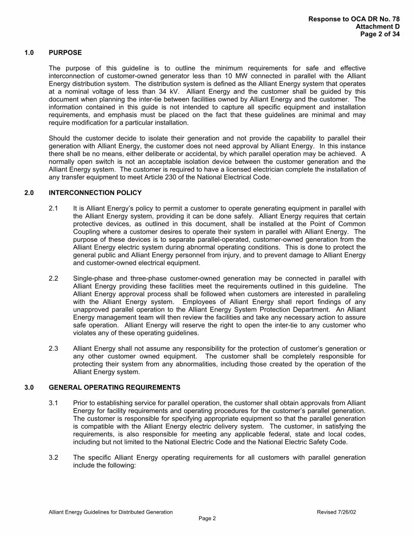
1.0 PURPOSE The purpose of this guideline is to outline the minimum requirements for safe and effective interconnection of customer-owned generator less than 10 MW connected in parallel with the Alliant Energy distribution system. The distribution system is defined as the Alliant Energy system that operates at a nominal voltage of less than 34 kV. Alliant Energy and the customer shall be guided by this document when planning the inter-tie between facilities owned by Alliant Energy and the customer. The information contained in this guide is not intended to capture all specific equipment and installation requirements, and emphasis must be placed on the fact that these guidelines are minimal and may require modification for a particular installation. Should the customer decide to isolate their generation and not provide the capability to parallel their generation with Alliant Energy, the customer does not need approval by Alliant Energy. In this instance there shall be no means, either deliberate or accidental, by which parallel operation may be achieved. A normally open switch is not an acceptable isolation device between the customer generation and the Alliant Energy system. The customer is required to have a licensed electrician complete the installation of any transfer equipment to meet Article 230 of the National Electrical Code.
2.0 INTERCONNECTION POLICY 2.1 It is Alliant Energy’s policy to permit a customer to operate generating equipment in parallel with
the Alliant Energy system, providing it can be done safely. Alliant Energy requires that certain protective devices, as outlined in this document, shall be installed at the Point of Common Coupling where a customer desires to operate their system in parallel with Alliant Energy. The purpose of these devices is to separate parallel-operated, customer-owned generation from the Alliant Energy electric system during abnormal operating conditions. This is done to protect the general public and Alliant Energy personnel from injury, and to prevent damage to Alliant Energy and customer-owned electrical equipment.
2.2 Single-phase and three-phase customer-owned generation may be connected in parallel with
Alliant Energy providing these facilities meet the requirements outlined in this guideline. The Alliant Energy approval process shall be followed when customers are interested in paralleling with the Alliant Energy system. Employees of Alliant Energy shall report findings of any unapproved parallel operation to the Alliant Energy System Protection Department. An Alliant Energy management team will then review the facilities and take any necessary action to assure safe operation. Alliant Energy will reserve the right to open the inter-tie to any customer who violates any of these operating guidelines.
2.3 Alliant Energy shall not assume any responsibility for the protection of customer’s generation or
any other customer owned equipment. The customer shall be completely responsible for protecting their system from any abnormalities, including those created by the operation of the Alliant Energy system.
3.0 GENERAL OPERATING REQUIREMENTS
3.1 Prior to establishing service for parallel operation, the customer shall obtain approvals from Alliant
Energy for facility requirements and operating procedures for the customer’s parallel generation. The customer is responsible for specifying appropriate equipment so that the parallel generation is compatible with the Alliant Energy electric delivery system. The customer, in satisfying the requirements, is also responsible for meeting any applicable federal, state and local codes, including but not limited to the National Electric Code and the National Electric Safety Code.
3.2 The specific Alliant Energy operating requirements for all customers with parallel generation
include the following:
Response to OCA DR No. 78Attachment D
Page 2 of 34

Alliant Energy Guidelines for Distributed Generation Revised 7/26/02 Page 3
3.2.1 Voltage Range
The customer shall operate their generator(s) to maintain the same voltage level as the Alliant Energy system at the point of common coupling. The customer must provide an automatic method of disconnecting their generator(s) from the Alliant Energy system if the voltage cannot be maintained within Alliant Energy limits as stated in Table 3.1.
3.2.2 Voltage Fluctuations
The operation of customer-owned Distributed Generation systems is not allowed to produce excessive flicker to adjacent customers, therefore, the customer shall not cause voltage fluctuations (flicker) in excess of 2% on the distribution system at the point of common coupling.
3.2.3 Frequency
All customer generation shall operate at 60-hertz. The customer shall provide and automatic disconnecting means from the Alliant Energy system when generation falls outside the values prescribed in Table 3.1.
Table 3.1: Voltage/Frequency Disturbance Delay & Trip Times
[1] Voltage based on 120V, nominal.
3.2.4 Harmonics
The customer’s generating equipment shall not introduce excessive distortion to the Alliant Energy sinusoidal voltage or current waveforms. Guideline values for total harmonic distortion shall be at or below values published in the latest issue
Range Trip Time Percentage Voltage[1] Seconds Cycles
<50% <60 0.166 10 50%-90% 60-108 2.0 120 90%-110% 108-132 Normal Operating Range
110%-120% 132-144 1.0 60 >120% >144 0.1 6
Frequency (Hz) Units <30kW <59.3 0.166 10 59.3-60.5 Normal Operating Range >60.5 0.166 10 Frequency (Hz) Units >30kW <57 0.166 10 57-59.3 1.0 60 59.3-60.5 Normal Operating Range >60.5 0.166 10
Response to OCA DR No. 78Attachment D
Page 3 of 34

Alliant Energy Guidelines for Distributed Generation Revised 7/26/02 Page 4
of ANSI/IEEE 519, “Recommended Practices and Requirements for Harmonic Control in Electrical Power Systems.” If the generation produces unacceptable harmonics during parallel operation, per IEEE Standard 519, it shall be required to be removed and locked-out from service until the problem is resolved.
3.2.5 System Protection
The customer is responsible for providing adequate protection for Alliant Energy facilities for conditions that arise during parallel-operated generation. The customer is also responsible for providing adequate protection to their facility under any Alliant Energy operating condition whether or not the parallel generation is in operation. Conditions may include but are not limited to:
• single phasing of supply, • system faults, • equipment failures, • abnormal voltage or frequency, • lightning and switching surges, • excessive harmonic voltages, • excessive negative sequence voltages, • separation from Alliant Energy supply (islanding).
The customer shall cooperate with Alliant Energy in the analysis of disturbances to either the customer’s facility or Alliant Energy’s electric system by gathering and providing access to any information relating to a disturbance, including information from oscillographs, protective relay targets and reports, breaker operations, power quality monitors and sequence of events recorders.
3.2.6 Power Factor
The customer shall maintain a power factor range of 95% lagging to 95% leading, measured at the point of common coupling. Failure of the customer to maintain a power factor within this range may result in rate penalties to the customer and/or discontinuation of the parallel operation with the customer’s generation. In some cases, the power factor requirement may be much closer to unity as negotiated in the interconnection agreement.
3.2.7 Synchronizing
The customer shall be solely responsible for synchronizing their generator(s) with the Alliant Energy system. Alliant Energy will have the right to review, approve and inspect the method of synchronization. Automatic synchronizing settings will not be changed following installation unless mutually agreed to by both parties. The customer must install proper sensing devices to sense a de-energized circuit to assure that a de-energized circuit of Alliant Energy is not energized.
3.2.8 Islanding
Under certain conditions with extended parallel operation, it would be possible for a part of the electrical power system to be disconnected from the rest of the utility grid and have the Generation System continue to operate and provide power to a portion of the electrical power system. This condition is called “islanding”. It is not possible to successfully reconnect the isolated circuit to the rest of the Alliant Energy system since there are no synchronizing controls associated with all of the possible locations of disconnection. Therefore, it is a requirement that the
Response to OCA DR No. 78Attachment D
Page 4 of 34

Alliant Energy Guidelines for Distributed Generation Revised 7/26/02 Page 5
Distributed Generation be automatically disconnected from the system immediately by protective relays for any condition that would cause the system to be de-energized. The Generation System must then either isolate with the customer’s load and/or be blocked from closing back into the electrical power system until the electrical power system is energized for several minutes from the normal utility source. Depending upon the size of the Distributed Generation and the electrical power system loads, it may be necessary to install direct transfer trip equipment from the Alliant Energy source to remotely trip the generation system to prevent islanding.
3.2.9 Reclosing
Alliant Energy provides automatic reclosing to transmission and distribution circuits. Upon request, these reclosing times for the Alliant Energy source breaker(s) will be given to the customer. It is the customer’s responsibility to design and maintain their system to properly isolate parallel generation upon loss of the Alliant Energy supply before any reclosing operation.
3.2.10 Interrupting Device
To properly isolate parallel generation from the Alliant Energy system, customers with three-phase generation shall provide a three-phase interrupting device with appropriate protective relays. Customers with single-phase generation shall provide at least a single-phase interrupting device with appropriate protective relays and/or other protective equipment. These devices shall also be capable of interrupting the maximum available fault current at that location. Three-phase devices shall interrupt all three phases simultaneously, and shall have a separate tripping control independent of the AC source, i.e., a DC battery and charger. This requirement may be waved for generation with a line-commutated inverter. The interrupting device shall be located within the customer’s facility in accordance with applicable codes. If specific site issues require that the interrupting device be located within an Alliant Energy facility, any wiring, installation, testing and maintenance of this device shall be accomplished by Alliant Energy personnel at the customer’s expense.
3.2.11 Grounding
Grounding shall be of sufficient size to handle the maximum available ground fault current and shall be designed and installed to limit step and touch potentials to safe levels as set forth in “IEEE Guide for Safety in AC Substation Grounding”, ANSI/IEEE Standard 80.
All electrical equipment shall be grounded in accordance with local, state and federal electrical and safety codes and applicable standards.
3.2.12 Transformer
Alliant Energy may require, at the customer’s expense, a dedicated transformer or transformers to serve the customer’s generation. Since transformer connections and configuration can significantly impact Alliant Energy electric system operation, Alliant Energy shall review and approve the configuration of any customer-owned interconnection transformer(s). This includes, but is not limited to, transformer connection configuration (delta, wye) and grounding method (solid ground, ungrounded, impedance grounded…). It is the customer’s
Response to OCA DR No. 78Attachment D
Page 5 of 34

Alliant Energy Guidelines for Distributed Generation Revised 7/26/02 Page 6
responsibility to receive written approval from Alliant Energy prior to purchasing any interconnection transformer(s).
3.2.13 Disconnection Means
The customer shall provide a disconnecting device for use by Alliant Energy as a means of electrically isolating the Alliant Energy system from the generation system and to establish working clearances for maintenance and repair work in accordance with Alliant Energy safety rules. This disconnecting device may be located at the point of common coupling between the customer and Alliant Energy’s electric power system, or it may be located between the generation system and the customer’s load. Depending on system configuration and application, Alliant Energy may require that the disconnecting device have load break capability.
The disconnecting device shall be physically located for ease of access by Alliant Energy personnel. Access shall be available at all times for Alliant Energy personnel. The type of disconnecting device must allow for visual indication of the contact’s position. A molded-case type circuit breaker alone is not sufficient, as it does not allow visual indication of contact position. The disconnecting device’s operating handle shall be lockable only in the open position with a standard Alliant Energy padlock. All devices and their locations are subject to approval by Alliant Energy.
Alliant Energy reserves the right to open the disconnecting device and lock it in the open position. Conditions in which this may occur include but are not limited to:
• Alliant Energy personnel and/or public safety is threatened, • repair or maintenance of Alliant Energy facilities, • inspection of customer’s generating and protective equipment reveals a
hazardous situation, • lack of customer maintenance or maintenance records, • generation interferes with other Alliant Energy customers and/or the Alliant
Energy electric system as outlined in these guidelines. 3.2.14 Communications
The customer shall employ qualified operators for the generating facility and for coordinating operations of the generation facility with Alliant Energy. The customer shall provide Alliant Energy with contact numbers for the generating facility, with at least one contact number designated as available 24 hours a day. The customer shall notify Alliant Energy of any operational constraint, including production schedule estimates (as applicable).
3.2.15 Routine Maintenance and Emergency Repairs
Alliant Energy performs routine maintenance and inspections of its distribution, substation and transmission facilities. The coordination of the maintenance of these facilities takes into account numerous factors, including but not limited to the capability to serve load, safety, customer requirements and economics. Alliant Energy will use reasonable efforts to schedule planned inspection and maintenance to mutually agreed to times that are designated to have minimal disruption on the operation of the generating facility.
Response to OCA DR No. 78Attachment D
Page 6 of 34

Alliant Energy Guidelines for Distributed Generation Revised 7/26/02 Page 7
Alliant Energy performs most routine maintenance during normal working hours. The customer may request that this maintenance occur outside of normal working hours or meet an expedited schedule. The customer agrees to reimburse Alliant Energy for any incremental costs for meeting special schedule requirements.
Under Emergency conditions the output of the customer-owned generation facility shall be adjusted to a safe operating level, including shutdown. Alliant Energy will take all prudent measures to return the electric delivery system to a normal operating state. Alliant Energy will not reimburse the customer for any costs associated with an unexpected shutdown during Emergency conditions.
4.0 PROTECTION REQUIREMENTS
Alliant Energy requires adequate interconnection protection to separate customer-owned generation from the Alliant Energy electric system. The purpose of this equipment is to detect customer energization of an Alliant Energy circuit that has been de-energized, detect the customer’s generation operating at an abnormal voltage or frequency, or detect a fault or abnormal condition on the Alliant Energy electric system that requires separation of the customer’s parallel generation facilities. The customer shall provide all required interconnection protective equipment. This equipment shall be approved by Alliant Energy and provide the protective functions specified within this guide. This equipment shall be located within the customer’s facility. If specific site issues require the equipment to be located within an Alliant Energy facility, any wiring, installation, testing and maintenance of this equipment shall be accomplished by Alliant Energy personnel at the customer’s expense. Note that the protection of the interconnection between Alliant Energy and the customer is given in this guideline -- it is the responsibility of the customer to provide protection for their own equipment. These protection schemes are only guidelines; final requirements will be established during the engineering process. 4.1 Requirements for Photovoltaic, Fuel Cell, Microturbine and other inverter-based systems (less
than 100 kVA) Adequate interconnection protection is typically provided as an integral part of these generation systems. Customers shall confirm that the power inverter used is classified as a non-islanding inverter conforming to IEEE P929 (Recommended Practice for Utility Interface of Photovoltaic Systems), and UL 1741 (Standard for Static Inverters and Charge Controllers for Use in Photovoltaic Power Systems).
4.2 Requirements for Single Phase Induction Generators (less than 20 kVA)
These relatively small generators operated in parallel with the Alliant Energy electric delivery system usually require adding fairly simple protection schemes. When a fault occurs on the Alliant Energy system, Alliant Energy will isolate the faulted line from the system fairly quickly. Because of the large imbalance between the load and generation, the voltage and frequency relays at the generator will detect the fault and isolate the generation. The specific protective relay requirements for this class of generator are shown on drawing A1.1 in Appendix 1.
4.3 Requirements for Small, Three Phase Generators (less than 200 kVA)
Small three phase generators can supply greater amounts of energy to a fault on the Alliant Energy system; therefore, additional protection is required.
Response to OCA DR No. 78Attachment D
Page 7 of 34

Alliant Energy Guidelines for Distributed Generation Revised 7/26/02 Page 8
The specific protective relay requirements for this class of generator are shown on drawing number A1.2 in Appendix 1.
4.4 Requirements for Large, Three Phase Generators (200 kVA or larger)
Large generators can deliver a significant amount of energy to a fault on the Alliant Energy electric delivery system. The level of protection for this class of generation is greater in order to provide high-speed separation of the generation during system disturbances. Output contacts of relays installed on these generators shall directly energize the trip coil of the customer’s breaker or an intermediate auxiliary tripping relay that directly energizes the breaker trip coil. The relaying system shall have a reliable source of power independent from the AC system (DC battery and charger) to assure proper operation of the protection scheme. The protective relays shall be utility grade devices as defined in ANSI/IEEE Standard C37.90, “Relays and Relay Systems Associated with Electric Power Apparatus.” All relays shall have appropriate test switches (ABB type FT-1 preferred) to allow testing the operation of the relay without unwiring or disassembling the relay. Relay settings shall be reviewed and approved by the Alliant Energy System Protection Department. The relays shall be grouped in dedicated panels or cabinets accessible to Alliant Energy personnel. Voltage transformers installed on the primary side of the step-down transformer connected phase to ground are required for some of the protective functions. A primary fused cutout and secondary fused safety switch are required to prevent accidental backfeed from wound-potential transformers. Current transformers shall have shorting terminal blocks as necessary for metering and relaying. Alliant Energy may require a communications channel be installed as part of the relay protection scheme for this class of generation. This communications channel may be a leased telephone circuit, power line carrier, Alliant Energy owned pilot wire, microwave, or other means determined by Alliant Energy. This communication circuit and associated communication equipment, at the both the customer and Alliant Energy facilities, shall be installed at the customer’s expense. This class of customer owned generation may be interconnected with the Alliant Energy electric system using various transformer connections. The required protective functions are dependent on the type interconnection transformer connection utilized for a particular installation. The specific protective relay requirements for this class of generator are shown on drawing numbers A1.3 through A1.6 in Appendix 1.
5.0 COMMISSIONING, TESTING AND MAINTENANCE REQUIREMENTS When the customer’s equipment has been installed and functionally tested by the customer, Alliant Energy shall witness final operational tests of the interconnection relay system. These tests will consist of verifying the relays have the correct voltages and currents, as well as function in the manner intended. Alliant Energy shall not be responsible for verifying any control or signal wiring not directly related to the interconnection relay. The customer is responsible for all relay settings, testing and calculations needed for protection of their equipment. Alliant Energy reserves the right to verify on demand the calibration of all protective equipment including relays, interrupting devices, etc., at point of common coupling. Verification may include the tripping of the inter-tie interrupting device by the protective relays. After proper operation of the equipment is demonstrated, Alliant Energy may request that a protective seal be placed on relaying equipment to prevent unauthorized tampering.
Response to OCA DR No. 78Attachment D
Page 8 of 34
Alliant Energy Guidelines for Distributed Generation Revised 7/26/02 Page 9
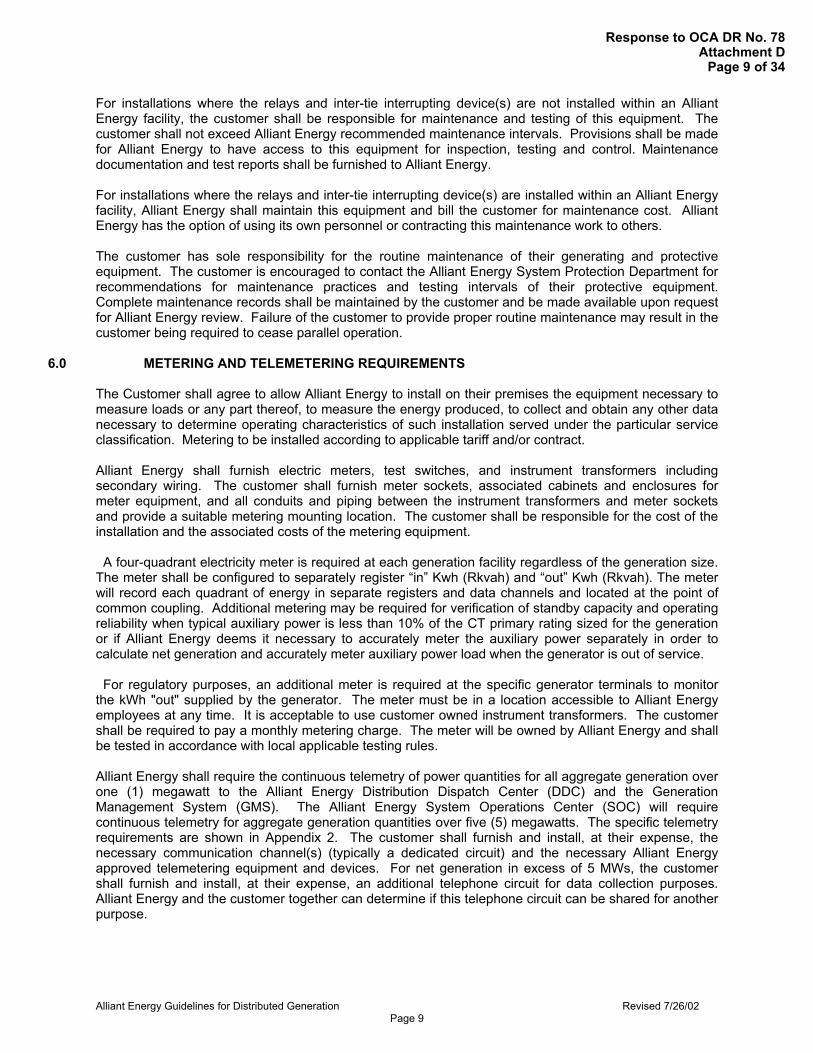
For installations where the relays and inter-tie interrupting device(s) are not installed within an Alliant Energy facility, the customer shall be responsible for maintenance and testing of this equipment. The customer shall not exceed Alliant Energy recommended maintenance intervals. Provisions shall be made for Alliant Energy to have access to this equipment for inspection, testing and control. Maintenance documentation and test reports shall be furnished to Alliant Energy. For installations where the relays and inter-tie interrupting device(s) are installed within an Alliant Energy facility, Alliant Energy shall maintain this equipment and bill the customer for maintenance cost. Alliant Energy has the option of using its own personnel or contracting this maintenance work to others. The customer has sole responsibility for the routine maintenance of their generating and protective equipment. The customer is encouraged to contact the Alliant Energy System Protection Department for recommendations for maintenance practices and testing intervals of their protective equipment. Complete maintenance records shall be maintained by the customer and be made available upon request for Alliant Energy review. Failure of the customer to provide proper routine maintenance may result in the customer being required to cease parallel operation.
6.0 METERING AND TELEMETERING REQUIREMENTS The Customer shall agree to allow Alliant Energy to install on their premises the equipment necessary to measure loads or any part thereof, to measure the energy produced, to collect and obtain any other data necessary to determine operating characteristics of such installation served under the particular service classification. Metering to be installed according to applicable tariff and/or contract. Alliant Energy shall furnish electric meters, test switches, and instrument transformers including secondary wiring. The customer shall furnish meter sockets, associated cabinets and enclosures for meter equipment, and all conduits and piping between the instrument transformers and meter sockets and provide a suitable metering mounting location. The customer shall be responsible for the cost of the installation and the associated costs of the metering equipment. A four-quadrant electricity meter is required at each generation facility regardless of the generation size. The meter shall be configured to separately register “in” Kwh (Rkvah) and “out” Kwh (Rkvah). The meter will record each quadrant of energy in separate registers and data channels and located at the point of common coupling. Additional metering may be required for verification of standby capacity and operating reliability when typical auxiliary power is less than 10% of the CT primary rating sized for the generation or if Alliant Energy deems it necessary to accurately meter the auxiliary power separately in order to calculate net generation and accurately meter auxiliary power load when the generator is out of service. For regulatory purposes, an additional meter is required at the specific generator terminals to monitor the kWh "out" supplied by the generator. The meter must be in a location accessible to Alliant Energy employees at any time. It is acceptable to use customer owned instrument transformers. The customer shall be required to pay a monthly metering charge. The meter will be owned by Alliant Energy and shall be tested in accordance with local applicable testing rules. Alliant Energy shall require the continuous telemetry of power quantities for all aggregate generation over one (1) megawatt to the Alliant Energy Distribution Dispatch Center (DDC) and the Generation Management System (GMS). The Alliant Energy System Operations Center (SOC) will require continuous telemetry for aggregate generation quantities over five (5) megawatts. The specific telemetry requirements are shown in Appendix 2. The customer shall furnish and install, at their expense, the necessary communication channel(s) (typically a dedicated circuit) and the necessary Alliant Energy approved telemetering equipment and devices. For net generation in excess of 5 MWs, the customer shall furnish and install, at their expense, an additional telephone circuit for data collection purposes. Alliant Energy and the customer together can determine if this telephone circuit can be shared for another purpose.
Response to OCA DR No. 78Attachment D
Page 9 of 34

Alliant Energy Guidelines for Distributed Generation Revised 7/26/02 Page 10
Instrument transformers
a. Current and voltage transformers used for revenue metering shall meet or exceed an accuracy class of 0.3%.
b. When sizing current transformers, the rating factor should be considered to optimize light load or reverse load situations.
c. When metering resides at distribution voltage, higher accuracy CTs, such as the General Electric “Accu-bute” TM should be used.
d. Connected burdens shall not exceed the burden rating of any transformer. e. Instrument transformer secondaries shall be limited to the electricity meters and transducers
providing data for operational purposes, if applicable. Test switches shall be installed to allow independent testing an/or maintenance so as to not interrupt the operation of the other devise utilizing the secondary circuits of the instrument transformers.
f. Where revenue metering instrument transformers shall reside inside customer owned primary switchgear, on a case-by-case basis, the switchgear manufacturer may install the company owned instrument transformers at their factory.
g. Instrument transformers will normally be located at the overhead-to-underground primary service drop and will be of the 15KV class for 12.4 KV or 13.08 KV distribution systems.
Net generation meters and gross generation meters used for revenue
a. Meters shall be form 9, 3 element, for 4 wire systems and form 5, 2 element, for 3 wire systems. The meter shall be socket type.
b. Meters shall meet or exceed the latest version of American National Standard Institute (ANSI) C12.20 (Electricity Meters 0.2 and 0.5 accuracy class).
c. Meters shall be solid-state type capable to record delivered and received KWH (Rkvah) separately.
d. Meters shall have individual registers, recorder data channels, and outputs, if applicable, for each measured value.
e. Meters shall be required to calculate and record for transformer losses if the metering is located on the low side of the transformer and the point of ownership change is on the high side of the transformer.
f. Meters shall be equipped with recorder under glass with mass memory of at least 35 days of storage for the total number of data channels required. Where net generation exceeds 5 MWs, meters shall be equipped with internal modem.
g. For net generation of 5 MW and greater, the meter shall be equipped with a form “C” pulse output for input into an Alliant Energy RTU. An isolation rely is not required when the meter and RTU are on the same ground plane.
h. For net generation of 5 MW and greater, an analog option board may be installed in the meter in place of installing transducers, if applicable.
i. Unless mutually agreed upon, all meters shall be tested on a schedule that meets or exceeds the periodic test intervals per local state requirements.
Auxiliary meters
a. Meters shall be form 9, 3 element, for 4 wire systems and form 5, 2 element, for 3 wire systems. The meter shall be socket type.
b. Meters shall meet or exceed the latest version of American National Standard Institute (ANSI) C12.20 (Electricity Meters 0.2 and 0.5 accuracy class).
c. Meters shall measure KWH and be equipped with recorder under glass with at least 35 days of storage.
d. For generation at exceeds 5 MW, meters shall be equipped with an internal modem and connected to the telephone system.
e. Meters shall be tested on the same interval as the generation meter.
7.0 COSTS INCURRED
Response to OCA DR No. 78Attachment DPage 10 of 34

Alliant Energy Guidelines for Distributed Generation Revised 7/26/02 Page 11
The Customer shall agree to install, operate and maintain their parallel generation facilities without cost to Alliant Energy. It shall also be the Customer’s responsibility to install, operate and maintain this system safely. The Customer shall be responsible for any costs required to upgrade the Alliant Energy electric delivery system to provide parallel operation. This may include, but is not limited to, upgrade of transformer insulation levels, installation of upgraded lightning arresters, distribution line upgrade, and/or the replacement of circuit breakers due to increased fault current levels. It shall also include all engineering costs associated with equipment additions and/or replacements. Any equipment to be installed on Alliant Energy property shall be accomplished by Alliant Energy personnel at the customer’s expense. The specific details of these costs will be explained in the Interconnection Agreement.
8.0 DESIGN REVIEW PROCESS An Application and Approval Process shall guide the customer and Alliant Energy employees. This process includes the submittal of an Application (see Appendix 3) and a project one-line drawing of the proposed installation. This information shall be furnished in sufficient detail to allow Alliant Energy to review the project requirements. This submittal will also include the customer’s proposed interconnection relay system. The customer will also pay a $280 non-refundable fee for each Application submitted to Alliant Energy. The customer may be required to pay additional study fees, depending on the complexity of the installation. Alliant Energy will inform the customer of any additional fees prior to starting any additional studies. The customer should begin their detailed design only after Alliant Energy review of the initial application and one-line drawing. Alliant Energy will commit to an installation time frame only after sufficient design information has been furnished to assure the agreed upon requirements are being met. The customer must consider the time constraints of Alliant Energy when scheduling the project. The customer shall allow a reasonable amount of time (typically six to eighteen months) after acceptance of the one-line and relay system design for any modifications to Alliant Energy facilities. Significant modifications may require longer lead times. All Applications for Parallel Operation with Alliant Energy are to be directed to the appropriate Account Manager. The Account Manager will act as the project manager and be responsible for following an Application and Approval Process. After the project is determined to be feasible, a joint meeting may be held between the customer and Alliant Energy to discuss the financial aspects of the installation. A separate meeting may take place to organize the stages of installation. Should the customer, at any time, determine that the project is not feasible after submitting their application, the customer shall verify cancellation of the application in writing.
9.0 GLOSSARY Alternating Current (AC): That form of electric current that alternates or changes in magnitude and polarity (direction) in what is normally a regular pattern for a given time period called frequency.
Ampere (Amp): The unit of current flow of electricity. It is to electricity as the number of gallons per minute is to the flow of water. One ampere flow of current is equal to one coulomb per second flow.
Automatic: Self-acting, operated by its own mechanism when actuated by some impersonal influence as, for example, a change in current strength; not manual; without personal intervention.
Automatic Reclosing: A circuit breaker has automatic reclosing when means are provided for closing without manual intervention after it has tripped under abnormal conditions.
Automatic Tripping (Automatic Opening; Automatic Disconnecting): The opening of a circuit breaker under predetermined conditions without the intervention of an operator.
Response to OCA DR No. 78Attachment DPage 11 of 34

Alliant Energy Guidelines for Distributed Generation Revised 7/26/02 Page 12
Circuit: A conducting path through which an electric current is intended to flow.
Circuit Breaker: A device for interrupting a circuit between separable contacts under normal or fault conditions.
Closed Transition Transfer: In this scheme, a customer’s source of power is transferred from Xcel Energy to its own generation and vice-versa while momentarily connecting the two systems together. Here, the Customer’s load is not interrupted at all during the transfer process. The time duration of the momentary parallel (connection) of the two systems together is only long enough to safely start and bring the Customer’s generation into synchronization or to safely shut down the generation. The parallel is typically completed within 30 seconds.
Current: A flow of electric charge measured in amperes.
Current Transformer (CT): A transformer intended for metering, protective or control purposes, which is designed to have its primary winding connected in series with a circuit carrying the current to be measured or controlled. A current transformer normally steps down current values to safer levels. A CT secondary circuit must never be open circuited while energized. Delta Connected Circuit: A three phase circuit with three source windings connected in a closed delta (triangle). A closed delta is a connection in which each winding terminal is connected to the end (terminal) of another winding.
Demand: The rate at which electric power is delivered to or by a system; normally expressed in kilowatts, megawatts, or kilovolt-amperes.
Direct Current (DC): An electric current flowing in one direction only and substantially constant in value.
Disconnect: A device used to isolate a piece of equipment. A disconnect may be gang operated (all poles switched simultaneously) or individually operated.
Dispatchable: Capable of having generator output (real and reactive power) adjusted ("dispatched") upon request of Alliant Energy power system operator. The adjustment includes capability to start-up and shut down generating units.
Distributed Generation: Electrical generation facilities of 10 MW of capacity or less connected to a utility through a Point of Common Coupling. Distributed Resources: Sources of electric power that are not directly connected to the bulk power transmission system. Distributed Resources includes both generators and energy storage technologies. Electric Power System: Equipment and apparatus owned by Alliant Energy, including overhead and underground facilities, service entrance equipment, meters, transformers, etc., which make up the central station energy delivery system. Emergency: A condition or situation that in the reasonable good faith determination of the affected party based on Good Utility Practice contributes to an existing or imminent physical threat of danger to life or a significant threat to health, property or the environment.
Energy Losses: The general term applied to energy lost in the operation of an electrical system. Losses can be classified as Transformation Losses, Transmission Line Losses or System Losses.
Frequency: The number of cycles occurring in a given interval of time (usually one second) in an electric current. Frequency is commonly expressed in hertz.
Fuse: A short piece of conducting material of low melting point, which is inserted in a circuit for the purpose of opening the circuit when the current reaches a certain value.
Generator: Any device producing electrical energy, i.e., rotating generators driven by wind, steam turbines, internal combustion engines, hydraulic turbines, solar, etc.; or any other electric producing device, including energy storage technologies. Generation System: The interconnected Distributed Generator(s), controls, relays, switches, breakers, transformers and associated wiring and cables.
Response to OCA DR No. 78Attachment DPage 12 of 34

Alliant Energy Guidelines for Distributed Generation Revised 7/26/02 Page 13
Good Utility Practice: Any of the practices, methods and acts engaged in or approved by a significant portion of the electric utility industry during the relevant time period, or any of the practices, methods and acts which, in the exercise of reasonable judgment in light of the facts known at the time the decision was made, could have been expected to accomplish the desired result at a reasonable cost consistent with good business practices, reliability, safety and expedition. Good Utility Practice is not intended to be limited to the optimum practice, method, or act to the exclusion of all others, but rather to be acceptable practices, methods, or acts generally accepted in the region.
Ground: A term used in electrical work in referring to the earth as a conductor or as the zero of potential. For safety purposes, circuits are grounded while any work is being done on or near a circuit or piece of equipment in the circuit; this is usually called protective or safety grounding.
Hertz (Hz): The term denoting frequency, equivalent to cycles per second.
Interrupting Capacity: The amount of current a switch, fuse, or circuit breaker can safely interrupt.
Interruption: A temporary discontinuance of the supply of electric power.
Island: A part of an interconnected system may be isolated during a system disturbance and start operating as a subsystem with its own generation, transmission and distribution capability. Then the subsystem becomes an island of the main interconnected system without a tie. In such a case, the islanded system and the main interconnected system will operate at different frequencies and voltages. Kilovolt (kV): One thousand volts.
Kilovolt-Ampere (kVA): One thousand volt amperes. See the definition for Apparent Power.
Kilowatt (kW): An electric unit of power that equals 1,000 watts.
Kilowatthour (kWh): One thousand watts of power supplied for one hour. A basic unit of electric energy equal to the use of 1 kilowatt for a period of one hour.
Lagging Power Factor: Occurs when reactive power flows in the same direction as real power.
Leading Power Factor: Occurs when reactive power flows in the opposite direction of real power.
Line Losses: Electrical energy converted to heat in the resistance of all transmission and/or distribution lines and other electrical equipment.
Long Term Parallel Operation: During normal operation of the generator, the generator stays electrically interconnected with the Alliant Energy system.
One-Line Diagram: A diagram in which several conductors are represented by a single line and in which various devices or pieces of equipment are denoted by simplified symbols. The purpose of such a diagram is to present an electrical circuit or circuits in a simple way so that their function can be readily grasped.
Open Transition Transfer: In this scheme, a customer’s source of power is transferred from Source 1 to Source 2 and vice-versa without momentarily connecting the two sources together. Here, the Customer’s load is interrupted momentarily during the transfer process through a mechanical or electrical interlock.
Parallel Operation: The operation of a customer-owned generator while connected to the Alliant Energy electric power system. Parallel operation may be required solely for the Customer's operating convenience or for the purpose of delivering power to Alliant Energy.
Peak Load: The maximum electric load consumed or produced in a stated period of time.
Peak Shaving: Generator operation that results in reducing customer's peak load or demand. Closed-transition peak shaving is the condition where the generator is in a parallel operation with Alliant Energy's system. Open-transition peak shaving is the condition where the generator is not connected in parallel with the Alliant Energy System.
Point of Metering: The point where metering equipment (meters, transducers, current transformers, potential transformers, etc.) is or will be installed to measure the power flow and energy exchange between Alliant Energy and the Customer.
Response to OCA DR No. 78Attachment DPage 13 of 34

Alliant Energy Guidelines for Distributed Generation Revised 7/26/02 Page 14
Power: Actual, Active or Real Power. The time rate of transferring or transforming energy or the power that accomplishes work. Measured in Watts.
Power Factor: The ratio of actual power (kW) to apparent power (kVA).
Power Flow: One-way power flow is the condition where the flow of power is entirely into the Customer's facility. Two-way power flow is the condition where the net flow of power may be either into or out of the Customer's facility depending on the operation of the generator and other customer load.
Point of Common Coupling: The point where the Generation System is connected to the Alliant Energy Electrical Power System.
Protection: All of the relays and other equipment that are used to open the necessary circuit breakers to clear lines or equipment when trouble develops.
QF: Qualifying Facility. An Independent Power Producer (IPP) that has met criteria to be certified by FERC as a Qualifying Facility and that has rights established by the PURPA of 1978.
Reactive Power: (VAR) The power that oscillates back and forth between inductive and capacitive circuit elements without ever being used. The function of reactive power is to establish and sustain the electric and magnetic fields required to perform useful work.
Received Energy: Energy received by Alliant Energy from the Customer.
Reclose: To return a circuit breaker to its closed position after it has opened by relay action.
Relay: A device that is operative by a variation in the condition of one electric circuit to affect the operation of another device in the same or in another electric circuit.
Self-Excited: An electric machine in which the field current is secured from its own armature current.
Self-Service Generators: Generators operated in parallel with the Alliant Energy System only for the purpose of reducing the Customer’s peak load. These generators are not normally dispatchable by Alliant Energy.
Separately Excited: Use of an exciter for sending current through the field windings of an electric machine in place of taking the field current from its own armature current.
Switch: A device for making, breaking or changing the connections in an electric circuit.
Synchronism: Expresses the condition across an open circuit wherein the voltage sine wave on one side matches the voltage sine wave on the other side in frequency and amplitude without phase angle difference.
Transformer: An electric device, without continuously moving parts, in which electromagnetic induction transforms electric energy from one or more other circuits at the same frequency, usually with changes of value of voltage and current.
Utility Grade Relays: Relays that meet IEEE standards C37.90, C37.90.1, and C37.90.2.
Voltage: Electric potential or potential difference expressed in volts.
Volt-Ampere: A unit of apparent power in an alternating-current circuit.
VAR: Volt ampere reactive, see Reactive Power.
Watt-Hour: A unit of work or energy equivalent to the power of one watt operating for one hour.
Wye or "Y" Connected Circuit (Star Connected): A three-phase circuit in which windings of all three phases have one common connection.
Response to OCA DR No. 78Attachment DPage 14 of 34

Alliant Energy Guidelines for Distributed Generation Revised 3/14/02 Appendix 1, Page 1
Appendix 1
General Guidelines for
Protection Specifications
And One-Line Diagrams
Response to OCA DR No. 78Attachment DPage 15 of 34

Alliant Energy Guidelines for Distributed Generation Revised 3/14/02 Appendix 1, Page 2
Symbols List for One-Line Diagrams DrawingA1.0
Revised 2/11/02
27
M
G
Distribution Transformer: A transformer used to change the voltage from a distribution voltage level(2400V-34kV) to a level for use by the customer (typically 277/480V, 120/208V, or 120/240V).
Fuse: A short piece of conducting material of low melting point, which is inserted in a circuit for thepurpose of opening the circuit when the current reaches a certain value.
Disconnect: A device used to isolate a piece of equipment. A disconnect may be gang operated (all polesswitched simultaneously) or individually operated.
Circuit Breaker: A device for interrupting a circuit between separable contacts under normal or faultconditions.
Current Transformer (CT): A transformer intended for metering, protective or control purposes, which isdesigned to have its primary winding connected in series with a circuit carrying the current to be measuredor controlled. A current transformer normally steps down current values to safer levels. A CT secondarycircuit must never be open circuited while energized.
Relay: A device that is operative by a variation in the condition of one electric circuit to affect the operationof another device in the same or in another electric circuit. The number corresponds to a specific relaytype. The relay types are shown in the Table on page 6 of this Appendix 1.
Meter: A device used to measure the flow of electricity (in kWh) between Alliant Energy and the customer.The meter may measure flow in one or both directions.
Generator: Any device producing electrical energy, i.e., rotating generators driven by wind, steamturbines, internal combustion engines, hydraulic turbines, solar, etc.; or any other electric producingdevice, including energy storage technologies.
Ground: A term used in electrical work in referring to the earth as a conductor or as the zero of potential.For safety purposes, circuits are grounded while any work is being done on or near a circuit or piece ofequipment in the circuit; this is usually called protective or safety grounding.
Potential Transformer (CT): A transformer intended for metering, protective or control purposes, which isdesigned to change the voltage from a distribution or utilization voltage level to a level for metering orprotection purposes (typically 24V or 48V).
Response to OCA DR No. 78Attachment DPage 16 of 34

Alliant Energy Guidelines for Distributed Generation Revised 3/14/02 Appendix 1, Page 3
Protection Requirements One-Line DiagramSingle Phase Induction Generators Less than 20 kW
G
27 81U59 81O
DistributedGeneration
LocalLoad
Visible, LockableDisconnect
DrawingA1.1
Revised 2/9/02
Point of Common Coupling
Customer
Alliant Energy
M
M
Alliant EnergyDistribution System
(less than 34kV)
Response to OCA DR No. 78Attachment DPage 17 of 34

Alliant Energy Guidelines for Distributed Generation Revised 3/14/02 Appendix 1, Page 4
Protection Requirements One-Line DiagramSynchronous and Induction Generators Larger than 20 kW and Smaller than
200 kW Connected Through a wye-wye Transformer
27 81U59 81O
DistributedGeneration
LocalLoad
Visible, LockableDisconnect
DrawingA1.2
Revised 2/9/02
Point of Common Coupling
Customer
Alliant Energy
M
M
Alliant EnergyDistribution System
(less than 34kV)
G
Response to OCA DR No. 78Attachment DPage 18 of 34

Alliant Energy Guidelines for Distributed Generation Revised 3/14/02 Appendix 1, Page 5
Protection Requirements One-Line DiagramSynchronous and Induction Generators Larger than 200 kW Connected
Through a grounded wye-delta (or ungrounded wye) Transformer
27 59T59I 81U
DistributedGeneration
LocalLoad
Visible, LockableDisconnect
DrawingA1.3
Revised 2/9/02
27
25
Alliant EnergyDistributionSubstation Customer
Alliant Energy
Point of Common Coupling
or
51G
51V 21-2or
81O
25
VT(1)
VT(1)
VT(3)
(Note 3)
Notes:1. 51V or 21-2 Required only if27 operating time is too slow forfeeder faults.2. A 21-2 device may be usedin place of 51V device.3. The 25 and 27 devices at theAlliant Energy Substation arerequired if generation is greaterthan 50% of minimum feederload.
(Notes 1 and 2)
M
M
G
Response to OCA DR No. 78Attachment DPage 19 of 34

Alliant Energy Guidelines for Distributed Generation Revised 3/14/02 Appendix 1, Page 6
Protection Requirements One-Line DiagramSynchronous and Induction Generators Larger than 200 kW Connected
Through a grounded wye-grounded wye Transformer
27 59T59I 81U
DistributedGeneration
LocalLoad
Visible, LockableDisconnect
DrawingA1.4
Revised 2/9/02
27
25
Alliant EnergyDistributionSubstation
Customer
Alliant Energy
Point of Common Coupling
51G
51V
21-2
or
81O
25
VT(1)
VT(1)
VT(3)
(Note 3)
Notes:1. 51V or 21-2 Required only if27 operating time is too slow forfeeder faults.2. A 21-2 device may be usedin place of 51V device.3. The 25 and 27 devices at theAlliant Energy Substation arerequired if generation is greaterthan 50% of minimum feederload.4. Use 46 device if line/feederunbalance will result intransformer overload.
(Notes 1 and 2)
or
(Note 4)
51 46 51N
(Note 4)
M
M
G
Response to OCA DR No. 78Attachment DPage 20 of 34

Alliant Energy Guidelines for Distributed Generation Revised 3/14/02 Appendix 1, Page 7
Protection Requirements One-Line DiagramSynchronous and Induction Generators Larger than 200 kW Connected
Through a delta (or ungrounded wye)-grounded wye Transformer
27 59T59I 81U
DistributedGeneration
LocalLoad
Visible, LockableDisconnect
DrawingA1.5
Revised 2/9/02
27
25
Alliant EnergyDistributionSubstation
Customer
Alliant Energy
Point of Common Coupling
51G
51V 21-2or
81O
25
VT(1)
VT(1)
VT(3)
(Note 3)
Notes:1. 51V or 21-2 Required only if27 operating time is too slow forfeeder faults.2. A 21-2 device may be usedin place of 51V device.3. The 25 and 27 devices at theAlliant Energy Substation arerequired if generation is greaterthan 50% of minimum feederload.
(Notes 1 and 2)
50 51 51N
59N 27N
VT(1)
or
M
M
G
Response to OCA DR No. 78Attachment DPage 21 of 34

Alliant Energy Guidelines for Distributed Generation Revised 3/14/02 Appendix 1, Page 8
Protection Requirements One-Line DiagramSynchronous and Induction Generators Larger than 200 kW Connected
Through a delta (or ungrounded wye)-delta (or ungrounded wye) Transformer
27 59T59I 81U
DistributedGeneration
LocalLoad
Visible, LockableDisconnect
DrawingA1.6
Revised 2/9/02
27
25
Alliant EnergyDistributionSubstation
Customer
Alliant Energy
Point of Common Coupling
51V 21-2or
81O
25
VT(1)
VT(1)
VT(3)
(Note 3)
Notes:1. 51V or 21-2 Required only if27 operating time is too slow forfeeder faults.2. A 21-2 device may be usedin place of 51V device.3. The 25 and 27 devices at theAlliant Energy Substation arerequired if generation is greaterthan 50% of minimum feederload.
(Notes 1 and 2)
50 51 51N
59N 27N
VT(1)
or
or
M
M
G
Response to OCA DR No. 78Attachment DPage 22 of 34
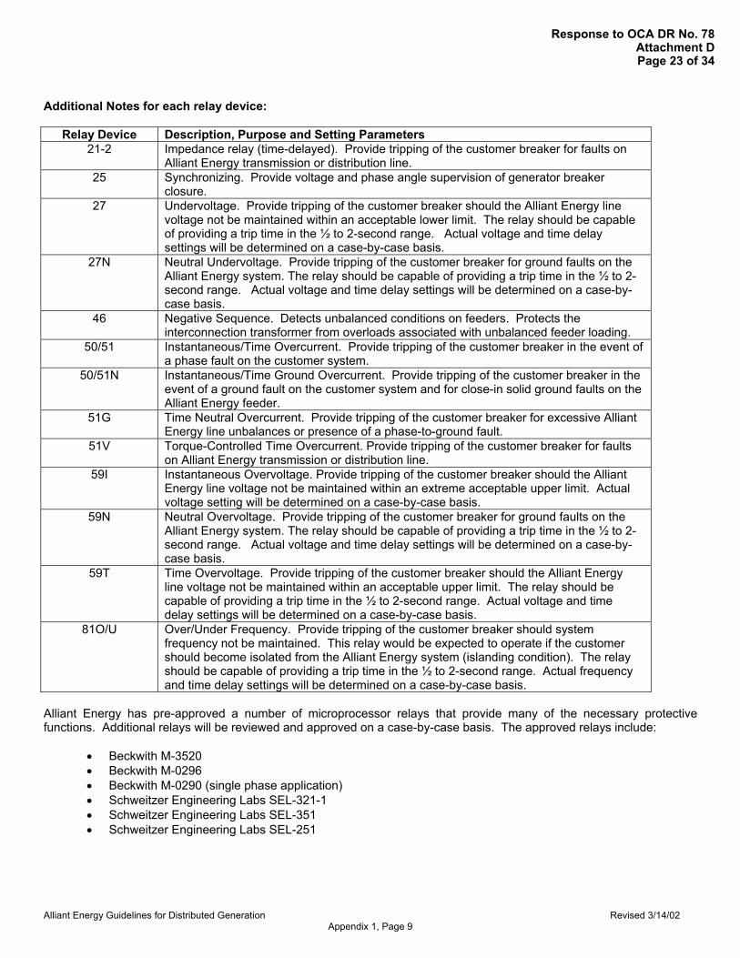
Alliant Energy Guidelines for Distributed Generation Revised 3/14/02 Appendix 1, Page 9
Additional Notes for each relay device:
Relay Device Description, Purpose and Setting Parameters 21-2 Impedance relay (time-delayed). Provide tripping of the customer breaker for faults on
Alliant Energy transmission or distribution line. 25 Synchronizing. Provide voltage and phase angle supervision of generator breaker
closure. 27 Undervoltage. Provide tripping of the customer breaker should the Alliant Energy line
voltage not be maintained within an acceptable lower limit. The relay should be capable of providing a trip time in the ½ to 2-second range. Actual voltage and time delay settings will be determined on a case-by-case basis.
27N Neutral Undervoltage. Provide tripping of the customer breaker for ground faults on the Alliant Energy system. The relay should be capable of providing a trip time in the ½ to 2-second range. Actual voltage and time delay settings will be determined on a case-by-case basis.
46 Negative Sequence. Detects unbalanced conditions on feeders. Protects the interconnection transformer from overloads associated with unbalanced feeder loading.
50/51 Instantaneous/Time Overcurrent. Provide tripping of the customer breaker in the event of a phase fault on the customer system.
50/51N Instantaneous/Time Ground Overcurrent. Provide tripping of the customer breaker in the event of a ground fault on the customer system and for close-in solid ground faults on the Alliant Energy feeder.
51G Time Neutral Overcurrent. Provide tripping of the customer breaker for excessive Alliant Energy line unbalances or presence of a phase-to-ground fault.
51V Torque-Controlled Time Overcurrent. Provide tripping of the customer breaker for faults on Alliant Energy transmission or distribution line.
59I Instantaneous Overvoltage. Provide tripping of the customer breaker should the Alliant Energy line voltage not be maintained within an extreme acceptable upper limit. Actual voltage setting will be determined on a case-by-case basis.
59N Neutral Overvoltage. Provide tripping of the customer breaker for ground faults on the Alliant Energy system. The relay should be capable of providing a trip time in the ½ to 2-second range. Actual voltage and time delay settings will be determined on a case-by-case basis.
59T Time Overvoltage. Provide tripping of the customer breaker should the Alliant Energy line voltage not be maintained within an acceptable upper limit. The relay should be capable of providing a trip time in the ½ to 2-second range. Actual voltage and time delay settings will be determined on a case-by-case basis.
81O/U Over/Under Frequency. Provide tripping of the customer breaker should system frequency not be maintained. This relay would be expected to operate if the customer should become isolated from the Alliant Energy system (islanding condition). The relay should be capable of providing a trip time in the ½ to 2-second range. Actual frequency and time delay settings will be determined on a case-by-case basis.
Alliant Energy has pre-approved a number of microprocessor relays that provide many of the necessary protective functions. Additional relays will be reviewed and approved on a case-by-case basis. The approved relays include:
• Beckwith M-3520 • Beckwith M-0296 • Beckwith M-0290 (single phase application) • Schweitzer Engineering Labs SEL-321-1 • Schweitzer Engineering Labs SEL-351 • Schweitzer Engineering Labs SEL-251
Response to OCA DR No. 78Attachment DPage 23 of 34

Alliant Energy Guidelines for Distributed Generation Revised 3/14/02 Appendix 2, Page 1
Appendix 2
Parallel Operation with Alliant Energy
Generation Telemetry Requirements
Response to OCA DR No. 78Attachment DPage 24 of 34

Alliant Energy Guidelines for Distributed Generation Revised 3/14/02 Appendix 2, Page 2
Distributed Generation Greater than 1 MW and Less than 5 MW This document refers to generator sites that have the following criteria:
1.) The aggregate generation output capability is greater than 1 MW and less than 5 MW connected
to the Alliant Energy electric power system at a voltage less than 34 kV. 2.) The generator(s) may or may-not be involved in sales transactions through the Alliant Energy
System. This document also refers to any generation less than 1 MW that is involved in wholesale power transactions.
For the reasons listed below, the Alliant Energy DDC (Distribution Dispatch Center) and GMS (Generation Management System) require continuous telemetry for certain data points & types: 1.) Determination and monitoring of real-time limit thresholds and/or violations. (Wholesale
Transactions) 2.) Historical tracking of limit thresholds and/or violations. (Wholesale Transactions) 3.) Monitoring of Alliant Energy System Demand – Real-time and historical 4.) Monitoring of Reactance Flows - Real-time and historical 5.) Monitoring of Generator On or Off Line Status 6.) De-coupling of Generation and Load for Network Applications such as State Estimation and
Security Analysis.
Depending on the physical site configuration, some data points require direct instantaneous telemetry, and others can be calculated on the basis of other telemetered points. Required Data points:
Generation – Aggregate or Individual Units, depending on size and configuration 1.) Instantaneous - Generator Output (Mw) – Net if internal auxiliaries exist 2.) Instantaneous - Generator Output (Mvar) – Net if internal auxiliaries exist 3.) Hour End - Generator Output (Mwh Accumulated) – Net if internal auxiliaries exist 4.) Hour End - Generator Output (Mvarh Accumulated) – Net if internal auxiliaries exist 5.) Dedicated dial-up telephone communications to meter mass memory (MV90 Software) – Historical
performance. (For Merchant generation).
Point(s) of Common Coupling with Alliant Energy (May represents the Net of Customer Generation and Load) 1.) Interconnection Point (Mw) – Bi-Directional 2.) Interconnection Point (Mvar) – Bi-Directional 3.) Interconnection Point (Mwh Accumulated) – In and Out 4.) Interconnection Point (Mvarh Accumulated) – In and Out 5.) Dial-up telephone communications to meter (MV90 Software) – Revenue Billing
Some configurations may require “Total Load” (shown below) as an addition to, or a replacement of, the above “Point(s) of Service from Alliant Energy”
Total Load 1.) Total Load (Mw) 2.) Total Load (Mvar) 3.) Total Load (Mwh Accumulated) 4.) Total Load (Mvarh Accumulated) 5.) Dial-up telephone communications to meter (MV90 Software)
Response to OCA DR No. 78Attachment DPage 25 of 34

Alliant Energy Guidelines for Distributed Generation Revised 3/14/02 Appendix 2, Page 3
Status 1.) Status of all circuit breaker(s) that can disconnect a generator from the Alliant Energy System. 2.) Status of any bus tie circuit breakers
Response to OCA DR No. 78Attachment DPage 26 of 34

Alliant Energy Guidelines for Distributed Generation Revised 3/14/02 Appendix 2, Page 4
Distributed Generation 5 MW through 10 MW This document refers to generator sites that have the following criteria: 1.) The aggregate generation output capability is greater than 5 MW but less than 10 MW connected
to the Alliant Energy electric power system at a voltage less than 34 kV. 2.) The generator(s) may or may-not be involved in sales transactions through the Alliant Energy
System. For the reasons listed below, the Alliant Energy DDC (Distribution Dispatch Center), GMS (Generation Management System), and the SOC (System Operations Center) require continuous telemetry for certain data points & types: 1.) Determination and monitoring of real-time limit thresholds and/or violations. (Wholesale
Transactions) 2.) Historical tracking of limit thresholds and/or violations. (Wholesale Transactions) 3.) Monitoring of Alliant Energy System Demand - Real-time and historical 4.) Monitoring of Reactance Flows - Real-time and historical 5.) Monitoring of Generator On or Off Line Status 6.) De-coupling of Generation and Load for Network Applications such as State Estimation and
Security Analysis. Depending on the physical site configuration, some data points require direct instantaneous telemetry, and others can be calculated on the basis of other telemetered points. Required Data Points:
Generation – Aggregate or Individual Units, depending on size and configuration 1.) Instantaneous - Generator Output (Mw) – Net if internal auxiliaries exist 2.) Instantaneous - Generator Output (Mvar) – Net if internal auxiliaries exist 3.) Hour End - Generator Output (Mwh Accumulated) – Net if internal auxiliaries exist 4.) Hour End - Generator Output (Mvarh Accumulated) – Net if internal auxiliaries exist 5.) Dedicated dial-up telephone communications to meter mass memory (MV90 Software) –
Historical performance data.
Point(s) of Common Coupling with Alliant Energy
(May represent the Net of Customer Generation and Load) 1.) Interconnection Point (Mw) – Bi-Directional 2.) Interconnection Point (Mvar) – Bi-Directional 3.) Interconnection Point (Mwh Accumulated) – In and Out 4.) Interconnection Point (Mvarh Accumulated) – In and Out 5.) Dial-up telephone communications to meter (MV90 Software) – Revenue Billing
Some configurations may require “Total Load” (shown below) as an addition to, or a replacement of, the above “Point(s) of Service from Alliant Energy”
Response to OCA DR No. 78Attachment DPage 27 of 34

Alliant Energy Guidelines for Distributed Generation Revised 3/14/02 Appendix 2, Page 5
Total Load 1.) Total Load (Mw) 2.) Total Load (Mvar) 3.) Total Load (Mwh Accumulated) 4.) Total Load (Mvarh Accumulated) 5.) Dial-up telephone communications to meter (MV90 Software)
Reserve Auxiliary – Evaluate on a per project basis 1.) Reserve Auxiliary (Mw) 2.) Reserve Auxiliary (Mvar) 3.) Reserve Auxiliary (Mwh Accumulated) 4.) Reserve Auxiliary (Mvarh Accumulated)
Status 3.) Status of all circuit breaker(s) that can disconnect a generator from the Alliant Energy System. 4.) Status of any bus tie circuit breakers Bus Measurement(s) 1.) One kV measurement per generator bus
Response to OCA DR No. 78Attachment DPage 28 of 34

Alliant Energy Guidelines for Distributed Generation Revised 7/26/2002 Appendix 3
Appendix 3
Generation Interconnection Request
Response to OCA DR No. 78Attachment DPage 29 of 34

Alliant Energy Guidelines for Distributed Generation Revised 7/26/2002 Appendix 3
Distribution Interconnection Forms
Overview These forms are required for Interconnection of Distributed Generation to the Alliant Energy system. All customers wishing to install generation require the first form, "Distributed Generation Interconnection Request". This request, along with a detailed one-line diagram, should supply Alliant Energy with the necessary information for small (<20 kW) generators and pre-certified units. The second from, "Distributed Generation Request for Additional Information", may be required by customers with larger or more complicated installations. Alliant Energy will inform the customer when additional information is required. Distributed Generation Interconnection Request Provide contact information for the Owner, Design Engineer (if applicable) and Electrical Contractor. Also include the address of the proposed DG installation and the corresponding Alliant Energy account number (if available). Alliant Energy also requests Generator Data as part of this request. This data is typically available from the generator manufacturer. Alliant Energy also requests the type of fuel (Energy Source) that will be used to power the generation. This could include, natural gas, wind, hydro, diesel, etc. This information is required to determine if the installation is a Qualifying Facility (QF) in accordance with the Public Utility Regulatory Policies Act (PURPA) of 1978. Qualifying Facilities may entitle the customer to different rates reserved for renewable resources. Alliant Energy requests some basic technical information on this form. There is a list of pre-certified generators available on the Alliant Energy Distributed resources website, www.alliantenergy.com/xxxx, or a list may be obtained by contacting Alliant Energy at 1-(800) 972-5325. The remainder of the questions in this section pertain to whether or not the generator meets the requirements set forth in this document. An estimate of the yearly load is required on this form. The information required is the estimated annual load at the site where the generation will be installed and the estimated yearly output, in kWh, of the generator. The customer may obtain the previous year's usage by contacting Alliant Energy at 1-800 Alliant, or the Account Manager (if applicable). Finally, Alliant Energy requests a brief description of the facility along with a detailed one-line diagram showing the generation and the location of the visible disconnect. Distributed Generation Request for Additional Information This form may be required from customers installing larger or more complex DG installations. The information required on this form is technical data required for Alliant Energy to perform a more detailed engineering study of the installation. The customer may need a design engineer to complete this information.
Response to OCA DR No. 78Attachment DPage 30 of 34

INSTRUCTIONS:1. This request is required for customers who are intending to install generation on its premises that will operate connected to the Alliant Energy Distribution System.
3. The request may be submitted electronically or mailed to the following address: Alliant Energy, Delivery System Planning G.O. 16, PO Box 351, Cedar Rapids, IA 52406-0351 IA, MN, or IL Customers (include $280.00 application fee) Alliant Energy, Delivery System Planning 4902 N. Biltmore Lane, P.O. Box 77007, Madison, WI 53707-1007 WI Customers (see WI Tech Guideline for appropriate application fee)
Company Name Contact Name
Fax No.
( ) ( )
City State Zip
( ) ( )
( ) ( )
Page 1 of 2
75-1681 09/02
ESTIMATED CONSTRUCTION DATESStart Date Completion Date
kWh
City
ESTIMATED LOAD INFORMATIONEstimated Annual Consumption (without generation) Estimated Annual Generator Production
Phone No.
TECHNICAL REQUIREMENTS
YES
kWh
Street Address E-mail Address
ZipState
DESIGN ENGINEERCompany Name
City State Zip
OWNER/APPLICANT INFORMATION
PROPOSED LOCATION OF GENERATOR UNIT
E-mail Address
Phone No.
Fax No.
Street Address Account No.
2. This request is intended to provide Alliant Energy personnel with information to determine requirements for interconnection of the customer's generation to the Alliant Energy System.
Contact Name
Contact NameELECTRICAL CONTRACTOR
Phone No.
Street Address
Fax No.
Street Address E-mail Address
City State Zip
GENERATOR DATAManufacturer Model No. Serial No.
Rated Output for One Unit (kW) Rated Voltage (volts) Rated Power Factor (%)
Version No.
Energy Source
Is This Generator Pre-Certified?
Iowa
Phase(s)Type (Synchronous, Induction, Inverter, etc.) Total Number of Units Installed
1 Phase 3 Phase
Illinois Wisconsin
Meets Control, Protection and Safety Requirements?
YES NO
DISTRIBUTED GENERATION INTERCONNECTION REQUEST
NO YES NO
Meets Power Quality Requirements?
YES NOMichigan
Performs to Relaying and Equipment Requirements?
Which state(s) is the Unit Pre-Certified
Response to OCA DR No. 78Attachment DPage 31 of 34

Does the customer intend to:
DateCUSTOMER SIGNOFF SECTION
Applicant Signature
Offset usage?
Sell power to a third party over the Alliant Energy system?
Page 2 of 2
Attach a one-line diagram of the installation to this request form. The one-line diagram should show the specific location of the external disconnect. Provide a briefdescription of the generator operation, standby power, peak shaving.
Sell power to Alliant Energy?
Add brief description here:
DESCRIPTION OF INSTALLATION
Comments:
75-1681 09/02
FOR ALLIANT ENERGY USE ONLYDate Received DR Request No.
Date Into DR DB Assigned Planner
Response to OCA DR No. 78Attachment DPage 32 of 34

Alliant Energy Guidelines for Distributed Generation Revised 7/26/2002 Appendix 3
1. This form is required to provide additional information to Alliant Energy personnel for completion of an Interconnection Study.2. In addition to the information required on this form Alliant Energy requests a detailed one-line diagram of the proposed facility.
Name: DR Request #:
Unit Number:Manufacturer:Type:
Phases: 1 or 3Rated Output kW kVA
% on kVA base% on kVA base% on kVA base% on kVA base% on kVA base
Exciter data:Governor data:
Ohms OhmsOhms OhmsOhms Ohms
Design Letter:
Unit Number:Manufacturer:Serial Number:H.P. Rated: lb.-sq. ft.
Frequency (Hz):
Total number of units with listed specifications on site:
Date of manufacture:
Speed (RPM):
3. Complete this form for each proposed generator that will be installed on-site.
Energy Source (hydro, steam, wind, etc.):H.P. Max: Inertia Constant:
Prime Mover (Complete all applicable items)Type:
Date of Manufacture:
Rotor Resistance (Rr): Stator Resistance (Rs):
Zero Sequence Reactance (Xo):
kVars (full Load)
Stator Reactance (Xs):Short Circuit Reactance (Xd"):
Synchronous Reactance (Xd): Transient Reactance (X'd): Subtransient Reactance (X"d):Negative Sequence Reactance (Xs):
(Complete all applicable items, Copy this page as required for additional generators)
Synchronous Generator Data (If applicable)
Distributed Generation Request for Additional Information
Serial Number (each)
Rated Power Factor (%): Rated Voltage(Volts):
I 2t or K (heating time constant):
Rated Current (Amperes):Field Voltage (Volts): Field Current (Amps): Motoring Power (kW):
Neutral Grounding Resistor (if applicable):
Additional Information:
Induction Generator Data (If applicable)
Frame Size:Magnetizing Reactance (Xm): OhmsRotor Reactance (Xr):
Temp Rise (deg C°):Exciting Current:Rated Output (kW):Reactive Power Required: kVars (no Load)If this is a wound-rotor machine, describe any external equipment to be connected (resistor, rheostat, power converter, etc.) to rotor circuit, andcircuit configuration. Describe ability, if any, to adjust generator reactive output to provide power system voltage regulation.
Additional Information:
Response to OCA DR No. 78Attachment DPage 33 of 34

Alliant Energy Guidelines for Distributed Generation Revised 7/26/2002 Appendix 3
Manufacturer: Model #:
Minimum Short Circuit Ratio required:
Manufacturer:kVA Rating:High Voltage: kVLow Voltage: kV
% on kVA base% on kVA base% on kVA base
Manufacturer:
VoltsVolts
Multi Ratio? Start date:
Date:
Date Received:
Construction Schedule: Completion date:
AC or DC?
Customer Sign Off Area
Bushing Current Transformers (Max. ratio): Relay Accuracy Class:
Applicant Signature:
Control Voltage (Closing):Control Voltage (Tripping): Battery or Charged Capacitor?
AC or DC?
For Alliant Energy Use Only
Interrupting Rating (Amps):Interrupting Medium (vacuum, oil, gas, etc.): Insulating Medium (vacuum, oil, gas, etc.):
BIL Rating:
Trip Energy (Spring, Motor, Hydraulic, Pneumatic or Other):
Describe capability, if any, to adjust reactive output to provide voltage regulation:
NOTE: Attach all available calculations, test reports, and oscillographic prints showing inverter output voltage and current waveforms.
Model:
Connection (delta or wye):Connection (delta or wye):
Inverter Type (ferroresonant, step, pulse-width modulation, etc.):Type of Commutation (forced or line):
Date Entered into DB:
Date of Manufacture:Serial Number:
Close Energy (Spring, Motor, Hydraulic, Pneumatic or Other):
Transformer (If applicable)
Power Circuit Breaker (If applicable)
Inverter Data (If applicable)
Rated Ampacity (Amps):Rated Voltage (kilovolts):
Maximum Total Harmonic Distortion (%):Voltage Harmonic Distortion Maximum Individual Harmonic (%): Maximum Total Harmonic Distortion (%):
Minimum voltage for successful commutation:Current Harmonic Distortion Maximum Individual Harmonic (%):
Rated Power Factor (%): Rated Voltage (Volts): Rated Current (Amps):
Transformer Reactance (X): Neutral Grounding Resistor (if applicable)
Transformer Impedance (Z): Transformer Resistance (R):
Neutral solidly grounded?Neutral solidly grounded?
Closed transitionLong term Parallel operation
Type of Interconnected operationOpen Transition
Response to OCA DR No. 78Attachment DPage 34 of 34

Customer Makes
Generation Interconnect Request to
Alliant Energy(Form 75-0947
or in Wisconsin, PSC Form 6027
or 6028)
Request is Forwarded to
Delivery System Planning
Distribution Engineering
Executes Study and Reviews Application
Complete Interconnect
Agreement and PPA or
Applicable Tariff
Are Upgrades Required?
Complete Upgrades
Inspect Installation
Customer completes
OASIS Request
Interconnection Study is
Completed
FlowChart for Interconnection with Alliant Energy
Transmission or Distribution
Request?
Transmission Distribution
Yes
No
Response to OCA DR No. 78Attachment E
Page 1 of 1

Customer Makes DGInterconnection Requestto Alliant Energy Alongwith Appropriate Fee
($280)
DG InterconnectionRequest is Forwarded
to Delivery SystemPlanning
Alliant Energy ReviewsApplication and Executes
an Engineering Study.(Cost more than $280 ?)
Customer ApprovesStudy Cost?
Are Upgrades to theDistribution System
Required?
Complete theInterconnection
Agreement and PPA(if necessary)
Installation isInspected byAlliant Energy
Installation MeetsGuidelines?
Yes
No
An Alliant Energy Customer decides to install a distributedgenerator or would like further information. Customer submits
"Distribution Generation Interconnection Request" form.
The Interconnection Request Form is forwarded to theDelivery System Planning Department. Requests for DGin Wisconsin (WPL) will be forwarded to the Madisonoffice. All others (IPL) will be forwarded to the CedarRapids office.
The Interconnection Request is reviewed for completeness. ThePlanning Associate will inform the customer of any additional information
required. Some customers may be required to submit an additionalrequest form. Alliant Energy Distribution Engineering will then complete
the engineering study. Some customers may be required to pay anadditional fee to Alliant Energy for the study. Alliant Energy will inform
the customer of any additional costs prior to executing the study.
Application isComplete.
The application is complete withoutfurther action if the customer determinesthat the study cost is too high for theproject economics.
Alliant Energy Distribution Engineering will determine ifdistribution system upgrades are required through the
engineering study. Alliant Energy will inform the customer of anycosts that the customer is responsible for.
Alliant EnergyCompletes
SystemUpgrades
Alliant Energy will perform systemupgrades. This will take a minimum of 6months to complete and may take up to18 months.
Alliant Energy Delivery System Planning will develop an InterconnectAgreement from the standard Interconnect Agreement templates. Alliant will
also inform the customer of the appropriate tariff for the installation orEnergy Portfolio Services will develop a Purchased Power Agreement
(PPA) to account for energy supplied to the Alliant Energy system.
DR Goes On-Line The installation is now allowed togenerate.
Alliant Energy will inspect the customer's installation at theInterconnection Point to determine if the installation meets the
Alliant Energy guidelines. Alliant Energy assumes no liability byaccepting the installation.
Alliant Energy will inform the customer if the installationmeets the guidelines. The customer will be informed of
any necessary changes if the installation does not meetguidelines.
Yes
No
Yes
No
Flowchart for Interconnection with the Alliant Energy Distribution SystemResponse to OCA DR No. 78
Attachment FPage 1 of 1