Embed Size (px)
Citation preview
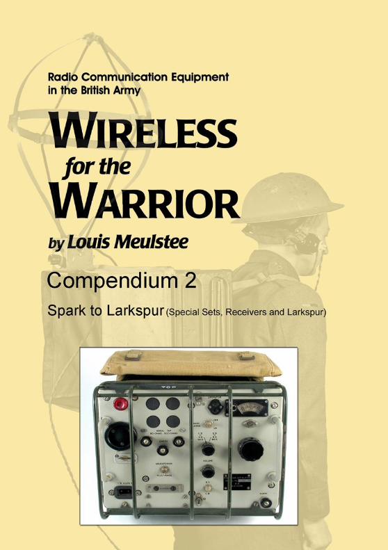
1
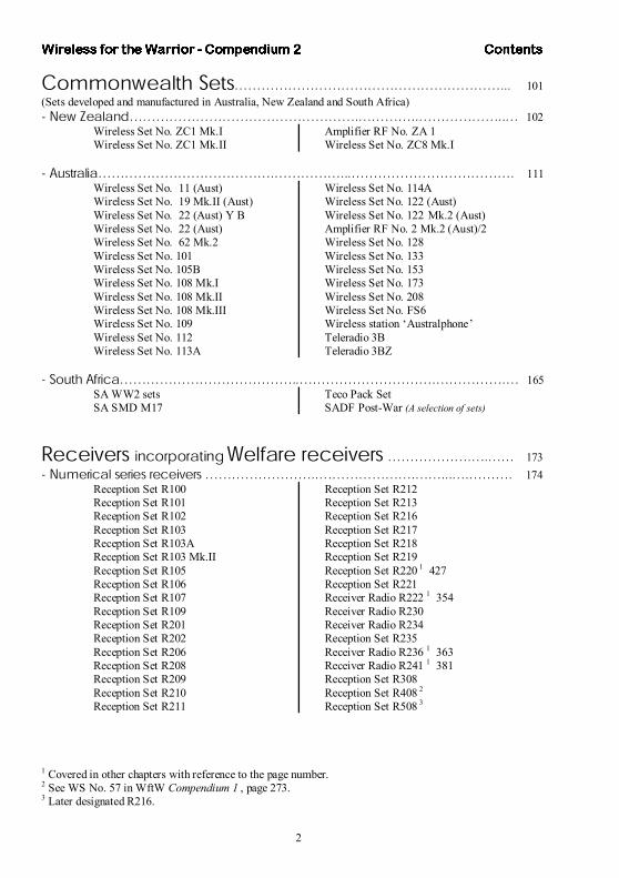
ݱ²¬»²¬ ��ò�����òòò������òò������ò���ò��ò 1
ß½µ²±©´»¼¹»³»²¬ ������������������òò�ò�ò�ò 5
ײ¬®±¼«½¬·±² �òòò�����������������òò���òò���ò 7
Í°»½·¿´ Í»¬ô λ½»·ª»® ¿²¼ Ô¿®µ°«®
Í°»½·¿´ Í»¬��òò�����������òòò�����ò����ò� 10ó ݱ³³»®½·¿´ô ÎßÚô ß¼³·®¿´¬§ ¿²¼ ±¬¸»® »¬ ¿¼±°¬»¼ º±® ß®³§ «» �����òò 11
Sender 5GWireless Set AD 67Wireless Set AD 77Wireless Set HS1Wireless Sender SWB 8EWireless Sender SWB 11EWireless Set T1154Transmitter T1190
Wireless Set SCR-188-AWireless Set SCR-245Wireless Sender BC-610RCA Transmitter ET-4331RCA Transmitter ET-4332-BRCA Transmitter ET-4336RCA Transmitter ET-4750Transmitter Cdn No. 33
Wireless Set Hallicrafters HT-9
ó Ù®±«²¼ ñß·® »¬��������òò�������������ò���� 40Wireless Set TR 1143Wireless Set Burndept CN 348Wireless Set Burndept BE 201 Wireless Set BCC 46U Station Radio C48
Wireless Set D 141Station Radio A43R Mk.2ASSU ‘Tentacle’Sarbe Beacon Mk.3Beacon Set Radio MR 343
ó Í°»½·¿´ »¬�����������ò�����������������òòò� 69Golden Arrow Mk.IGolden Arrow Mk.IISpecial Sets Types 1 to 6
Special Forces SetsWireless Station S.P.FGun Sound Ranging
- Ó·½»´´¿²»±« ¿²¼ ´±½¿´ °¿¬¬»®² »¬������������ò������ 84Early Army Chain and Diplomatic Service stations in China Captain Childs sets Lieut. Dagg setsThe Tibet political mission (1936/37)Unidentified stations Hermes Midget Transreceiver Marconi type H6 and type H9a portable sets
- Û¨°»®·³»²¬¿´ »¬ô §¬»³ ¿²¼ ·²¬®«³»²¬òòòòòòòòòòòòòòòòòòòòòòòòòòòòòòòòòòòòòòòòòòòòòòòòòòòòòòòòòò 93Crystal test oscillatorBarrage balloon receiver
Spur Link StationWireless Set ZC 178
It should be noted that some sets which would normally be categorised in the Larkspur erasection are for reasons of their functionality dealt with in other sections, notably inGround/Air sets and Numerical series receivers .
2
ݱ³³±²©»¿´¬¸ Í»¬��������������������òòò 101(Sets developed and manufactured in Australia, New Zealand and South Africa)ó Ò»© Æ»¿´¿²¼�����������������ò����òò������òò� 102
Wireless Set No. ZC1 Mk.IWireless Set No. ZC1 Mk.II
Amplifier RF No. ZA 1Wireless Set No. ZC8 Mk.I
ó ß«¬®¿´·¿�������������ò�����òòò������������ò 111Wireless Set No. 11 (Aust)Wireless Set No. 19 Mk.II (Aust)Wireless Set No. 22 (Aust) Y BWireless Set No. 22 (Aust)Wireless Set No. 62 Mk.2Wireless Set No. 101Wireless Set No. 105BWireless Set No. 108 Mk.IWireless Set No. 108 Mk.IIWireless Set No. 108 Mk.IIIWireless Set No. 109Wireless Set No. 112Wireless Set No. 113A
Wireless Set No. 114A Wireless Set No. 122 (Aust)Wireless Set No. 122 Mk.2 (Aust)Amplifier RF No. 2 Mk.2 (Aust)/2Wireless Set No. 128Wireless Set No. 133Wireless Set No. 153Wireless Set No. 173Wireless Set No. 208Wireless Set No. FS6Wireless station ‘Australphone’Teleradio 3BTeleradio 3BZ
ó ͱ«¬¸ ߺ®·½¿�������������òò����������ò�����ò� 165SA WW2 setsSA SMD M17
Teco Pack SetSADF Post-War (A selection of sets)
λ½»·ª»® ·²½±®°±®¿¬·²¹ É»´º¿®» ®»½»·ª»® ������ò�ò�� 173ó Ò«³»®·½¿´ »®·» ®»½»·ª»® ��������òò�������ò��òòò�ò���ò 174
Reception Set R100Reception Set R101Reception Set R102Reception Set R103Reception Set R103AReception Set R103 Mk.IIReception Set R105Reception Set R106Reception Set R107Reception Set R109Reception Set R201Reception Set R202Reception Set R206Reception Set R208Reception Set R209Reception Set R210Reception Set R211
Reception Set R212Reception Set R213Reception Set R216Reception Set R217Reception Set R218Reception Set R219Reception Set R220 1 427Reception Set R221Receiver Radio R222 1 354Receiver Radio R230Receiver Radio R234 Reception Set R235Receiver Radio R236 1 363Receiver Radio R241 1 381Reception Set R308Reception Set R408 2
Reception Set R508 3
1 Covered in other chapters with reference to the page number.2 See WS No. 57 in WftW Compendium 1 , page 273. 3 Later designated R216.
3
ó ݱ³³»®½·¿´ô ÎßÚ ¿²¼ °»½·¿´ ®»½»·ª»® ¿¼±°¬»¼ º±® ß®³§ «»������òòòòò 207Reception Set R1100Receiver type R1132AReception Set R1294Reception Set R1359Reception Set CR100Reception Set UHF Special ReceptionSet DST100Receiver MCR1Receiver Radio Type 301Receiver Radio 328R
Reception Set Eddystone 358Reception Set Eddystone 730/4 Reception Set RC67Reception Set RG35Reception Set RS5EReception Set AR88Radio Receiver BC-312 and BC-342Hallicrafters ReceiversReceiver Radio Racal RA17 Mk.2
ó λ½»·ª»® ³¿²«º¿½¬«®»¼ ·² ß«¬®¿´·¿ô Ý¿²¿¼¿ ¿²¼ Ò»© Æ»¿´¿²¼�����òòòòò 232Reception Set Cdn R103 Mk.IReception Set (Canadian) VRLReception Set No. 1 (Aust)Reception Set No. 4 (Aust)
Reception Set No. 8C (Aust)Reception Set R5223Reception Set R5222, R5232, R5233
ó ß®³§ Þ®±¿¼½¿¬ ®»½»·ª»® ����òò����������ò���������ò 243Reception Set BP412Reception Set BP413
Reception Set BV611 and BV612
ó Þ®·¬·¸ ß®³§ É»´º¿®» ®»½»·ª»® ��������������ò������òò�� 246Communication Receiver type PCRBritish Army Welfare receivers
Receiver Broadcast BV613
ó Ò»© Æ»¿´¿²¼ ¿²¼ ß«¬®¿´·¿² É»´º¿®» ®»½»·ª»® ����òò�òò������òò��ò 250Reception Set AEW1 (NZ) Reception Set AEW2 (NZ)
Australian Welfare receivers (including: ASS Model V5, AWA C17020, Electrosound, Kriesler, `Philips ‘ACF’, SC 5V15, Tasma AM and Velco)
Ü·®»½¬·±² Ú·²¼·²¹ Í»¬ ¿²¼ ͧ¬»³���������ò�òòò� 254ó ન¬·²¹ ´±±° ÜÚ §¬»³ ���������������������òò�� 255
Aerial Loop DF A, B and CDF Station Mobile B/C No. 1DF Station Mobile B/C No. 2 DF Station Mobile B/C No. 2A (trailer)
DF Station Mobile B/C No. 2A (truck)DF Station Mobile B/C No. 3DF Station Mobile P.E. No. 1
ó ݱ³³»®½·¿´ Ë󬧰» ß¼½±½µ ÜÚ §¬»³ ��������������ò��� 270Reception Set DFG12Reception Set DFG24
Reception Set DFG26/5
ó ß®³§ Ë󬧰» ß¼½±½µ ÜÚ §¬»³���������������òò�����ò 273DF Station Transp. Adcock No. 1 DF Station Transp. Adcock No. 2
DF Station Transp. Adcock No. 3
ó Ó·½»´´¿²»±« ÜÚ »¬ ¿²¼ §¬»³����������������òò��� 279Reception Set DFP4Reception Set DFP5DF Attachment for WS Nos. 9 and 11DF Attachment for WS No. 18
DF Attachment for WS Nos. 19 and 22R216 Lightweight DF StationHigh Mast DF SystemTelefunken PST6 38 (Telegon)
4
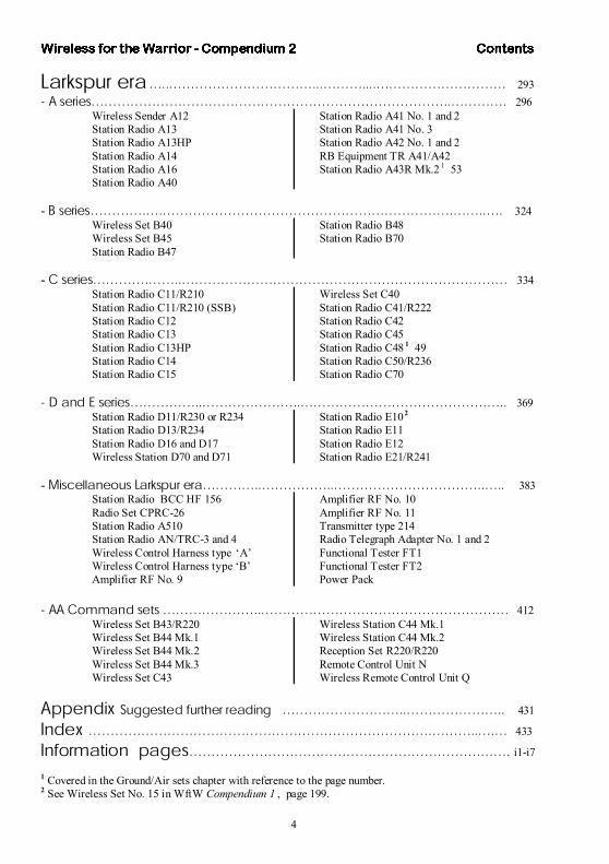
Ô¿®µ°«® »®¿�òò�����������òòò���òòòò���������� 293ó ß »®·»���������������������������òò����ò 296
Wireless Sender A12Station Radio A13Station Radio A13HPStation Radio A14Station Radio A16Station Radio A40
Station Radio A41 No. 1 and 2Station Radio A41 No. 3Station Radio A42 No. 1 and 2RB Equipment TR A41/A42Station Radio A43R Mk.2 1 53
- Þ »®·»����ò�ò����������������������ò��òò�ò 324Wireless Set B40Wireless Set B45 Station Radio B47
Station Radio B48Station Radio B70
- Ý »®·»����ò��òò������������������������� 334Station Radio C11/R210 Station Radio C11/R210 (SSB)Station Radio C12Station Radio C13Station Radio C13HP Station Radio C14Station Radio C15
Wireless Set C40Station Radio C41/R222Station Radio C42Station Radio C45Station Radio C48 1 49 Station Radio C50/R236 Station Radio C70
ó Ü ¿²¼ Û »®·»�����òò�������òò��������������ò�òò 369Station Radio D11/R230 or R234 Station Radio D13/R234 Station Radio D16 and D17Wireless Station D70 and D71
Station Radio E102
Station Radio E11Station Radio E12 Station Radio E21/R241
- Ó·½»´´¿²»±« Ô¿®µ°«® »®¿����òò�����òò�����������òò�òò 383Station Radio BCC HF 156Radio Set CPRC-26Station Radio A510Station Radio AN/TRC-3 and 4Wireless Control Harness type ‘A’Wireless Control Harness type ‘B’Amplifier RF No. 9
Amplifier RF No. 10Amplifier RF No. 11Transmitter type 214 Radio Telegraph Adapter No. 1 and 2Functional Tester FT1Functional Tester FT2Power Pack
ó ßß Ý±³³¿²¼ »¬ �������òò������������������� 412Wireless Set B43/R220 Wireless Set B44 Mk.1Wireless Set B44 Mk.2Wireless Set B44 Mk.3 Wireless Set C43
Wireless Station C44 Mk.1Wireless Station C44 Mk.2Reception Set R220/R220Remote Control Unit NWireless Remote Control Unit Q
ß°°»²¼·¨ Í«¹¹»¬»¼ º«®¬¸»® ®»¿¼·²¹ ���������òò�������òò 431
ײ¼»¨ ��������������������������ò���òò�ò� 433
ײº±®³¿¬·±² °¿¹»����������������������ò��ò i1-i7
1 Covered in the Ground/Air sets chapter with reference to the page number.2 See Wireless Set No. 15 in WftW Compendium 1 , page 199.
7
ײ¬®±¼«½¬·±²
The WftW Compendium series is a new addition to the ‘Wireless for the Warrior’ range of books coveringthe technical history of British Army communication equipment.The Compendium series is principally intended as a practical guide and reference source to vintage militarysignal communication equipment. It is particularly valuable to anyone with an interest, professionally orotherwise, in this subject, requiring an elementary but complete quick reference and recognition handbook.Containing condensed data summaries, liberally illustrated with photos and drawings, explanatory captionsand short descriptions of the main ancillaries, its pocket size format and laminated soft cover makes it an ideal reference and reliable companion for events such as auctions and radio rallies, or just for browsing at leisure.
Wireless for the Warrior (WftW) Compendium 1 ‘Spark to Larkspur’ (Wireless Sets 1910-1948) andCompendium 2 ‘Spark to Larkspur’ (Special Sets, Receivers and Larkspur ), the first books in this series, providebasic technical data on radio sets, radio stations and associated or related equipment used by the BritishArmy during the period 1910 to the late 1950s.
These two books are based on a massive amount of hitherto unpublished source material, includingmanuscripts from the projected but never produced WftW Volumes 'World War 1-the Spark and After' ,'Interwar Wireless' and 'Larkspur' , and condensed but reworked material from the WftW Volumes 1-3. Thenext two books in the Compendium series are entitle d ‘Foreign Equipment Data Sheets, Volume 13, SignalEquipment’, Parts 1 and 2. More titles may follow in due course.
Most of the equipment and systems covered in this present publication, Compendium 2, were standardproduction or procured from other Arms and commercial sources. It also includes some experimental sets,equipment with a limited employment, and a few sets which never came into production due to changedrequirements or visions which represented interesting, advanced and promising developments.
Compendium 2 is divided into five main sections and sub-divided into chapters by application, operationaluse, range or family of sets, and date of introduction. In some cases this arrangement is not followed: forexample, Ground to Air sets from the Larkspur era are placed in the Ground to Air, rather than the Larkspurera chapter. Where applicable, a page cross reference is provided in these cases.
The pocket size format with soft cover, easy to follow and uncomplicated layout of text, illustrations andtechnical details used for Compendium 1 and 2 is similar. However, in Compendium 1 each set, system oritem started on a right-hand page for reasons of convenience. This resulted in a number of undesirable blankpages and has been avoided in Compendium 2.
Sizes and measures noted in the Compendium 1 and Compendium 2 are as seen from the equipment frontpanel. Working ranges (as a rule very conservative, depending much on circumstances and not least the skillof the signaller using the set) and technical specifications are quoted from operator ’s handbooks, technicalmanuals and EMER’s, where available.
The year of introduction is generally very approximate, as the time span between the General Staffrequirement specification, development and construction of ‘A’ and ‘B’ models, troop trials, full scaleproduction and actual issue to the troops was usually long. For equipment procured from commercialsources, different Arms or from North America (probably already in production when the Army decided to use it), the introduction year quoted is that when the equipment was used for the first time in British (andCommonwealth) land forces.
During the process of gathering information and compiling Compendium 2 it was noted that in many casesthe name or nomenclature of a set or system had changed over the years, or it had become known under a very different name. Where applicable, earlier names were added, while keeping the last known commonlyused official name in the main list. This includes the index entries, although this unfortunately lead toconfusion in some cases.
44
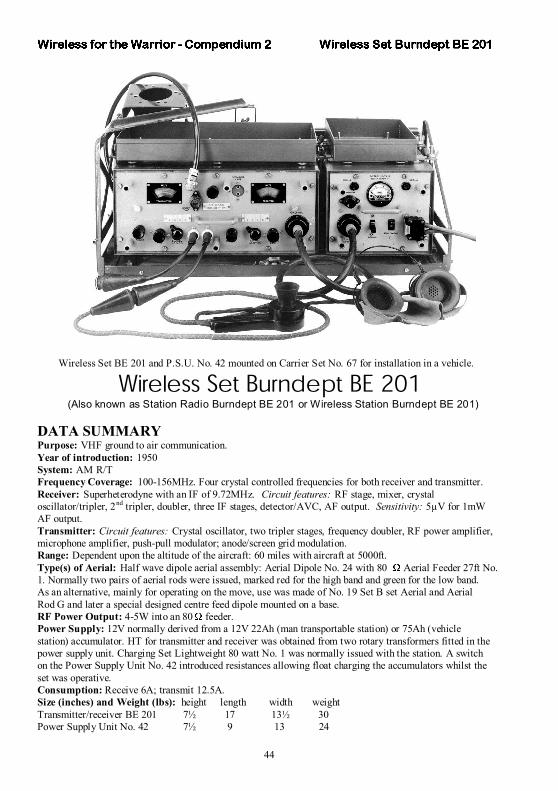
Wireless Set BE 201 and P.S.U. No. 42 mounted on Carrier Set No. 67 for installation in a vehicle.
É·®»´» Í»¬ Þ«®²¼»°¬ ÞÛ îðï(Also known as Station Radio Burndept BE 201 or Wireless Station Burndept BE 201)
DATA SUMMARY Purpose: VHF ground to air communication.Year of introduction: 1950 System: AM R/TFrequency Coverage: 100-156MHz. Four crystal controlled frequencies for both receiver and transmitter.Receiver: Superheterodyne with an IF of 9.72MHz. Circuit features: RF stage, mixer, crystaloscillator/tripler, 2nd tripler, doubler, three IF stages, detector/AVC, AF output. Sensitivity: 5µV for 1mWAF output.Transmitter: Circuit features: Crystal oscillator, two tripler stages, frequency doubler, RF power amplifier,microphone amplifier, push-pull modulator; anode/screen grid modulation.Range: Dependent upon the altitude of the aircraft: 60 miles with aircraft at 5000ft.Type(s) of Aerial: Half wave dipole aerial assembly: Aerial Dipole No. 24 with 80 Aerial Feeder 27ft No.1. Normally two pairs of aerial rods were issued, marked red for the high band and green for the low band.As an alternative, mainly for operating on the move, use was made of No. 19 Set B set Aerial and AerialRod G and later a special designed centre feed dipole mounted on a base.RF Power Output: 4-5W into an 80 feeder.Power Supply: 12V normally derived from a 12V 22Ah (man transportable station) or 75Ah (vehiclestation) accumulator. HT for transmitter and receiver was obtained from two rotary transformers fitted in thepower supply unit. Charging Set Lightweight 80 watt No. 1 was normally issued with the station. A switchon the Power Supply Unit No. 42 introduced resistances allowing float charging the accumulators whilst theset was operative.Consumption: Receive 6A; transmit 12.5A.Size (inches) and Weight (lbs): height length width weightTransmitter/receiver BE 201 7½ 17 13½ 30Power Supply Unit No. 42 7½ 9 13 24
144
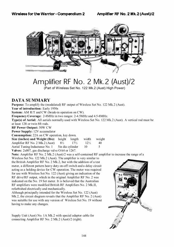
ß³°´·º·»® ÎÚ Ò±ò î Óµòî øß«¬÷ñî (Part of Wireless Set No. 122 Mk.2 (Aust) High Power)
DATA SUMMARY Purpose: To amplify the (modulated) RF output of Wireless Set No. 122 Mk.2 (Aust).Year of introduction: Early 1950s System: AM R/T and CW (break-in operation on CW).Frequency Coverage: 2-8MHz in two ranges: 2-4.5MHz and 4.5-8MHz.Type(s) of Aerial: All aerials normally used with Wireless Set No. 122 Mk.2 (Aust). A vertical rod must beat least 12ft or twin 8ft rods.RF Power Output: 50W CWPower Supply: 12V accumulatorConsumption: 22A on CW operation, key down.Size (inches) and Weight (lbs): height length width weightAmplifier RF No. 2 Mk.2 (Aust) 8½ 17½ 12½ 40Aerial Tuning Inductance No. 1 5in dia cylinder 10 5 Valves: 2x807, gas discharge valve OA4 or 1267. Note: Amplifier RF No. 2 Mk.2 (Aust)/2 was a self-contained RF amplifier to increase the range of a Wireless Set No. 122 Mk.2 (Aust). The amplifier is very similar tothe British Amplifier RF No. 2 Mk.2, but with the addition of a testmeter, a different pattern heavy duty on-off switch and a delay circuitacting as a holding device for CW operation. The meter was requiredfor use with Wireless Set No. 122 (Aust) giving an indication of theRF drive/RF output, which in the original Amplifier RF No. 2 wasindicated on the No. 19 Set meter. It is believed that the AustralianRF amplifiers were modified British RF Amplifiers No. 2 Mk.II,refurbished electrically and mechanically.Although principally intended for the Wireless Set No. 122 (Aust)Mk.2, the circuit diagram reveals that the Amplifier RF No. 2 (Aust)was suitable for use with any version of Wireless Set No. 19 withouthaving to make any changes.
Supply Unit (Aust) No. 1A Mk.2 with special adaptor cable forconnecting Amplifier RF No. 2 Mk.2 (Aust)/2 (right).
220
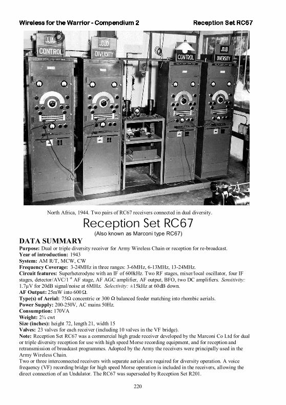
North Africa, 1944. Two pairs of RC67 receivers connected in dual diversity.
λ½»°¬·±² Í»¬ ÎÝêé(Also known as Marconi type RC67)
DATA SUMMARY Purpose: Dual or triple diversity receiver for Army Wireless Chain or reception for re-broadcast.Year of introduction: 1943 System: AM R/T, MCW, CWFrequency Coverage: 3-24MHz in three ranges: 3-6MHz, 6-13MHz, 13-24MHz.Circuit features: Superheterodyne with an IF of 600kHz. Two RF stages, mixer/local oscillator, four IFstages, detector/AVC/1 st AF stage, AF AGC amplifier, AF output, BFO, two DC amplifiers. Sensitivity:1.7µV for 20dB signal/noise at 6MHz. Selectivity: ±15kHz at 60dB down.AF Output: 25mW into 600 .Type(s) of Aerial: 75 concentric or 300 balanced feeder matching into rhombic aerials.Power Supply: 200-250V, AC mains 50Hz.Consumption: 170VA Weight: 2¾ cwtSize (inches): height 72, length 21, width 15 Valves: 23 valves for each receiver (including 10 valves in the VF bridge).Note: Reception Set RC67 was a commercial high grade receiver developed by the Marconi Co Ltd for dualor triple diversity reception for use with high speed Morse recording equipment, and for reception andretransmission of broadcast programmes. Adopted by the Army the receivers were principally used in theArmy Wireless Chain.Two or three interconnected receivers with separate aerials are required for diversity operation. A voicefrequency (VF) recording bridge for high speed Morse operation is included in the receivers, allowing the direct connection of an Undulator. The RC67 was superseded by Reception Set R201.
264
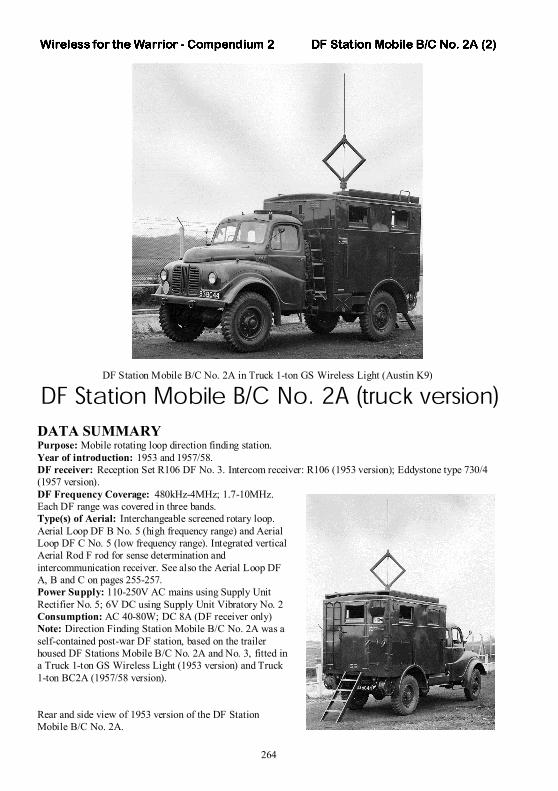
DF Station Mobile B/C No. 2A in Truck 1-ton GS Wireless Light (Austin K9)
ÜÚ Í¬¿¬·±² Ó±¾·´» ÞñÝ Ò±ò îß ø¬®«½µ ª»®·±²÷DATA SUMMARY Purpose: Mobile rotating loop direction finding station.Year of introduction: 1953 and 1957/58. DF receiver: Reception Set R106 DF No. 3. Intercom receiver: R106 (1953 version); Eddystone type 730/4 (1957 version).DF Frequency Coverage: 480kHz-4MHz; 1.7-10MHz.Each DF range was covered in three bands.Type(s) of Aerial: Interchangeable screened rotary loop.Aerial Loop DF B No. 5 (high frequency range) and AerialLoop DF C No. 5 (low frequency range). Integrated verticalAerial Rod F rod for sense determination andintercommunication receiver. See also the Aerial Loop DFA, B and C on pages 255-257.Power Supply: 110-250V AC mains using Supply UnitRectifier No. 5; 6V DC using Supply Unit Vibratory No. 2Consumption: AC 40-80W; DC 8A (DF receiver only)Note: Direction Finding Station Mobile B/C No. 2A was a self-contained post-war DF station, based on the trailerhoused DF Stations Mobile B/C No. 2A and No. 3, fitted ina Truck 1-ton GS Wireless Light (1953 version) and Truck1-ton BC2A (1957/58 version).
Rear and side view of 1953 version of the DF StationMobile B/C No. 2A.
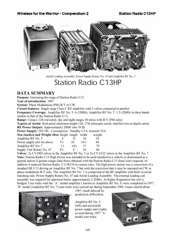
345
Aerial Loading Assembly, Power Supply Rotary No. 47 and Amplifier RF No. 7.
ͬ¿¬·±² ο¼·± ÝïíØÐDATA SUMMARY Purpose: Increasing the range of Station Radio C13.Year of introduction: 1967 System: Phase Modulation (PM) R/T or CW.Circuit features: Single stage Class C RF amplifier with 2 valves connected in parallel.Frequency Coverage: Amplifier RF No. 5: 6-12MHz; Amplifier RF No. 7: 1.5-12MHz in three bandssimilar to that of the Station Radio C13.Range: Using a 12ft rod aerial, day and night ranges 30 miles with R/T (PM only)Type(s) of Aerial: Rod aerial minimum length 12ft, 27ft telescopic aerial, end-fed wire or dipole aerial.RF Power Output: Approximately 200W into 70 .Power Supply: 24V DC. Consumption: Standby 3.5A, transmit 25A.Size (inches) and Weight (lbs): height length width weightAmplifier RF No. 5 8 12 16 24 Power supply unit for above 7¾ 10 14½ 44 Amplifier RF No. 7 11 14¾ 17 75 Supply Unit Rotary No. 47 8½ 8 16 40 Valves: 2x CV1905 valves in the Amplifier RF No. 5 or 2x CV 6122 valves in the Amplifier RF No. 7Note: Station Radio C13 High Power was intended to be used installed in a vehicle or dismounted as a ground station if greater ranges than those obtained with the Station Radio C13 alone were required. Inaddition it replaced Station Radio C11/R210 in certain roles. The high power station was a conversion of a standard SR C13 driving an Amplifier RF No. 7 but with the restriction that it may be operated on CW orphase modulation R/T only. The Amplifier RF No. 7 is comprised of the RF amplifier with built-in aerial matching unit, Power Supply Rotary No. 47 and Aerial Loading Assembly. The external loading coilassembly was required for operation below approximately 2.2MHz. At higher frequencies the coil isbridged. User trials with the ‘A ‘ model amplifier ( known as Amplifier RF No. 5) were completed in 1957. ‘B’ model (Amplifier RF No. 7) user trials were carried out during September 1960. Issues started about
1967, much delayed byproduction difficulties.
Amplifier RF No. 5 (left) and associatedpower supply unit (right)as used during 1957 ‘A’model user trials.
Wireless for the Warrior Volume 1 First published December 1995 by GC Arnold Partners, Broadstone, Dorset, U.K., ISBN 1898805 08 3
Volume 1 ('Wireless Sets No. 1 to 88' ) of Wireless for the Warrior is published in A4 format softback, and contains 360 pages, about 150 photographs, 320 line drawings/circuit diagrams and 130 tables. An explanation of the various Type Nomenclature systems used for Army radio equipment from WW1 to the 1960's is followed by descriptions of the sets themselves. The aim in each case has been to describe the history, technical details, aerials and accessories used with each set, together with spares schedules. Where a set was used in more than one application - for example as a mobile or a ground station - details of the variations are provided. Several versions and adaptations of the sets produced in Australia and Canada are also described. The descriptions of the sets are followed by a series of appendixes: Glossary of Terms;
Condensed data of Equipment; Accessories List; Army Valves Designation and Equivalents; Table of Frequency Coverage of Army Wireless Sets. All Wireless Sets in the numerical range (No. 1 to No. 88) are described. Detailed information is given on: Wireless Sets Nos. 1, 2, 3, 4, 5, 6, 7, 8,
9, Cdn 9, 11, 12, 13, 14, 15 (E10), 16, 17, X20A, 21, 23, 24, 26, 27, Cdn 27, 28, X32D, 33, 36, 37, Cdn 43, 47, 49 (B40/C40), X56A, 57, Cdn 58, 63, 76, 78 and 86 (C41/R222). Other sets mentioned: Wireless Sets Nos. 11 (Aust), 101 (Aust), 108 (Aust), 109 (Aust), 112 (Aust), 133 (Aust) and Admiralty Type 5G. Since the standard World War 2 sets are described in Volume 2, only a summary is given here; this includes:
Wireless sets Nos. 10, 18, 19, 22, C29, 31, 38, 42, 46, 48, C52, 53, 62, 68 and 88.
Wireless for the Warrior Volume 2 First published March 1998 by GC Arnold Partners, Broadstone, Dorset, U.K., ISBN 1898805 10 5
Volume 2 ( 'Standard Sets for World War 2' ) of Wireless for the Warrior is published in A4 hardback, containing 722 pages, and featuring 200 photographs, approximately 750 line drawings/circuit diagrams and 180 data tables. Comprehensive information on vehicle installations is included where appropriate, giving the book considerable appeal to military vehicle enthusiasts, as well as awakening memories of those who maintained or used these sets 'in anger'. It provides detailed information on the following standard World War 2 sets and other sets of which sufficient information was unavailable when Volume 1 was published:- Wireless Sets Nos. 10, 18, 19, 22, 31, 31AFV, 38, 38AFV, 42, 46, 48, 53, 62, 68, 88 and 88AFV - Wireless Sets Canadian Nos. 19, 29 and 52;
Australian Nos. 19, 22, 108, 122, 133 and 153 Other sets mentioned include: Burndept BE201, CN348, RCA ET-4332b, DF station PE No.1. Larkspur range: Station Radio B47, C42, C45
and C11/R210. Air Ministry: TR1143, TR1987. US Signal Corps: SCR-300, BC-610, AN/TRC-5 and AN/TRC-6. In the Appendixes the following items are covered: Glossary of Terms; Condensed Data of Equipment; Accessories; Army Valves Designations and Equivalents; Table of Frequency Coverage of Army Wireless Sets; References and Bibliography; Commercial Equipment; Miscellaneous Military Equipment;
Generating Sets and Secondary Batteries; Collecting and Safety; Vehicle Installations; Mains Power Supply Unit.

Wireless for the Warrior Volume 3 First published July 2001 by Wimborne Publishing Limited, Dorset, U.K., ISBN 0952063 35 2 The third Volume in the Wireless for the Warrior series, entitled ‘Reception Sets’ , is devoted to receivers (also known as Reception Sets) used in the British Army over the period 1932 to the 1960s. The contents of this Volume is principally concentrated on the R100 to R508 series, but many other receivers with different nomenclatures are covered. Volume 3 consists of eight main chapters, each dealing with a distinct group of receivers (in total more than 70 receivers), introductory and general information pages and a number of appendixes. It contains 546 pages and features 230 photographs, 470 line drawings and 220 data tables in A4 hardback format.
1 Army Reception Sets. 2 Reception Sets Adopted from other Arms. 3 Special Receivers. 4 Direction Finding Receivers. 5 Army Broadcast Reception Sets. 6 Commonwealth Army Reception Sets. 7 Commercial Receivers Adopted by the Army. 8 Army Welfare Reception Sets.
In the Appendixes are covered: - Condensed Data of Equipment. - Army Valve Designations and Equivalents . - Headphones in use in the British Army. A large number of related equipment and wireless sets are mentioned in Volume 3 including specialists’ vehicles and installation layout.
Wireless for the Warrior Volume 4 First published September 2004 by Wimborne Publishing Limited, Dorset, U.K., ISBN 0952063 36 0
The fourth Volume (‘ Clandestine Radio’) in the Wireless for the Warrior series is different in approach to the previous books. Although it still contains a mix of technical data, photographs, line drawings and circuit diagrams, no extensive descriptions are provided, principally to limit the number of pages but also for reasons of non-availability of detailed information for the majority of the sets. This Volume is a combined effort of Louis Meulstee, Rudolf Staritz and a number of other authors, notably Jan Bury, Erling Langemyr, Tor Marthinsen, Pete McCollum and Antero Tanninen, experts in their own fields and living in various parts of the world. The time period imposed on the selection of sets to be included in this volume stretches from about 1938 up to the early 1990s, approximately to the fall of the Berlin Wall.
It must be noted that apart from Clandestine, Agents or 'Spy' radio equipment, sets which were used by Special Forces, Partisans, Resistance, 'Stay Behind' organisations, Australian Coast
Watchers and Diplomatic Service are covered. Also included are selected associated power sources, intercept receivers, RDF equipment, High speed keyers, S-Phone, bugs and radio- and radar beacons such as Eureka/Rebecca. In the Appendix there is a list of abbreviations. Volume 4 is covered in a number of main chapters, describing equipment used or manufactured in a certain country. Information is included on more than 230 sets. It contains 692 pages in A4 hardback format, and
features over 850 photographs, 360 line drawings and 440 data tables.

The Wireless for the Warrior Compendium series is principally intended as a practical guide and reference source to vintage military signal communication equipment. It is particularly valuable to anyone with an interest, professionally or otherwise, in this subject, requiring an elementary but complete quick reference and recognition handbook. Containing condensed data summaries, liberally illustrated with photos and drawings, explanatory captions and short descriptions of the main ancillaries, its pocket size format and laminated soft cover makes it an ideal reference and reliable companion for events such as auctions and radio rallies, or just for browsing at leisure.
WftW Compendium 1
Spark to Larkspur (Wireless Sets 1910-1948) First published September 2009 by Emaus Uitgeverij, Groenlo, The Netherlands. ISBN 978 90 808277 2 1
Wireless for the Warrior Compendium 1 Spark to Larkspur (Wireless Sets 1910-1948) is published in a practical A5 softback format. It contains 354 pages and over 560 photographs, line drawings and tables, a comprehensive index , and a fold-out 'Chart of interrelationship of sets'. Compendium 1 is organised into three main sections being 'World War 1', further divided into chapters covering spark sets, CW sets, receivers, amplifiers and miscellaneous.
The second section, 'Interwar years' covers standard sets, experimental communication sets, experimental tank and AFV sets, early sets in the numerical series and miscellaneous items. Finally, the section 'World War 2' covers sets in the numerical series up to Wireless Set No. 88 AFV, wave-meters, aerial coupling equipment, wireless remote control units and Morse training sets.
WftW Compendium 2 Spark to Larkspur (Special Sets, Receivers and Larkspur)
First published August 2012 by Louis Meulstee, ISBN 978 90 819271 0 9 Wireless for the Warrior Compendium 2 ‘Spark to Larkspur’ (Special sets, Receivers and Larkspur) is published in a practical A5 softback format. It contains 215 different sets and systems in 458 pages, and over 1050 photographs, line drawings and tables. Included are a comprehensive index and a list of suggested further reading. Compendium 2 is divided into five main sections and sub-divided into chapters by application, operational use, range or family of sets, and date of introduction. The first section covers 'Special Sets' with chapters: commercial, RAF and other sets adapted for Army use; ground to air sets; special sets; miscellaneous and local pattern sets; experimental sets.
The 'Commonwealth Sets' section deals with equipment manufactured and/or used in Australia, New Zealand and South Africa.
'Receivers' are covered in a separate section comprising chapters on: numerical series; commercial, RAF and special receivers adopted for Army use; Receivers manufactured in Australia, Canada and New Zealand; Army broadcast and welfare-amenities receivers. ‘Direction Finding receivers and Systems’ include chapters on rotating loop DF systems; commercial U-type Adcock DF systems; Army U-type Adcock DF systems; miscellaneous DF sets and systems.
The final section covers the 'Larkspur' era of sets, including Anti-Aircraft Command sets.
WftW Compendium 3 and 4 Foreign Equipment Data Sheets Part 1 and 2
First published August 2012 by Louis Meulstee WftW Compendium 3: ISBN 978 90 819271 1 6 WftW Compendium 4: ISBN 978 90 819271 2 3
Wireless for the Warrior Compendium 3 and 4 contains a facsimile reprint of the German World War 2 publication entitled ‘ Signal Equipment’ (‘Nachrichtengerät’), also known as D50/13. The publication is Volume 13 in the ‘Foreign Equipment Data Sheets’ (‘Kennblätter fremden Geräts’), a series of German Army publications providing data on enemy equipment, principally from Belgium, England, France, North America, Russia and Switzerland. It was first issued to the German forces in July 1940, completely revised in 1941, with supplements issued in 1941, 1942 and 1943.
For practical reasons the reprint was split into two parts: Compendium 3 covering the Belgian, English, French and North American sections containing 225 different signal instruments in 474 pages, and Compendium 4 with the Russian and Swiss sections, containing 171 different signal instruments in 364 pages. For English-speaking readers an English introduction, table of contents, glossary and translation of original German sample pages are provided. The facsimile reprint represents the D50/13 publication as it was used issued and updated, including all supplements, of
which the last was issued in November 1943. ‘Foreign Equipment Data Sheets’ is a series of 15 different German Army publications providing principal data on enemy equipment ranging from small arms, heavy weapons, ammunition and vehicles, to communication equipment. They were compiled by the German high command, based on captured equipment and handbooks, but also from various (commercial) documents and journals, and issued to the German Forces as a guide to the reuse of the equipment. Original and complete copies are rare.
WftW Compendium 5 Signal Communication Equipment used by Enemy Nations
First published November 2012 by Louis Meulstee, ISBN 978 90 819271 3 0
Wireless for the Warrior Compendium 5 is a facsimile reprint of ‘Signal Communication Equipment used by Enemy Nations’ , a British publication providing technical and operational data on captured enemy signal communication equipment originating from Germany, Italy and Japan. It was produced by the Signals Research and Development Establishment (SRDE) in co-operation with M.I. 8 and first issued as a secret document in January 1944. The publication was a result of careful study and examination, based on captured equipment and handbooks, intended as a guide to the reuse of the equipment. At first glance the publication may be considered as the British
counterpart of the German ‘Kennblätter fremden Geräts, Heft 13, Nachrichtengerät’ (reprinted in WftW Compendium 3 and 4). However, the individual entries in ‘Signal Communication Equipment used by Enemy Nations’ are far more detailed and accurate. In addition it provide many practical details such as hints on the operation and maintenance of the sets, glossaries, nomenclatures with an explanation of the type numbering systems, and connections of plugs, sockets and valve bases. Original and
complete copies are very rare. This reprint reproduces the publication as it was originally issued, including all supplements with the amendment changes already carried out.

Wireless for the Warrior
Volumes 1- 4 and Compendium 1 Wireless for the Warrior Volumes 1 - 4 and Compendium 1 are available by mail order from Direct Book Service. The easiest and most convenient way to order is online via www.radiobygones.com (go to the ‘UK Store’ via the ‘EPE Online’ link) Books are normally kept in stock and despatched within seven days. It should also be noted that reduced postage rates may apply if more than one book is ordered. Contact the Direct Book Service for details.
Direct Book Service Wimborne Publishing Ltd 113 Lynwood Drive Merley, Winbourne Dorset BH21 1UU, England Phone: +44 (0)1202 880299 Fax: +44 (0)1202 843233 Email: [email protected] Website:www.epemag.com (‘UK Store’ tab)
Wireless for the Warrior Compendiums 2 - 5
Wireless for the Warrior Compendiums 2, 3, 4 and 5 are only available direct from the ‘Print On Demand’ printers via the internet on-line bookshop at www.lulu.com/spotlight/wftw . Print on demand (POD) is a printing technology and process in which new copies of a book are not printed until an order has been received, which means books can be printed one at a time.
Each order is printed and shipped locally, which minimizes time in transit and transit costs. For more information and up-to-date news about developments in the Wireless for the Warrior range of books, particularly the Compendium series, and a link to the bookshop see the Wireless for the Warrior website www.wftw.