Embed Size (px)
Citation preview

UGA DESIGN & CONSTRUCTION SUPPLEMENTAL GENERAL REQUIREMENTS & STANDARDS TERMS APRIL 30, 2020 00 00 02-1
00 00 02 TERMS
Athens-Clarke County (ACC)
Bid (or Base Bid)
BIM (Building Information Modeling)
Board of Regents of the University System of Georgia (Board of Regents or BOR)
Campus
The term refers to the University of Georgia’s main campus and Health Sciences Campus
in Athens, Georgia as well as all other Board of Regents UGA Property.
Center for Teaching and Learning (CTL)
Client
For OUA managed projects, the OUA is the Design Professional or Contractor’s Client. For FMD
managed projects, the FMD is the Design Professional or Contractor’s Client. The End-User is not
the Design Professional or the Contractor’s Client.
Contractor
The term “Contractor” means: General Contractor (GC) or Construction Manager (CM) or Design
Builder (DB).
Construction Contingency
This term shall also mean Contractor Contingency.
Design Bid Build (DBB)
Design - Build and/or Design – Builder (DB)
This term shall also mean Contractor.
Design & Construction Standards (Standards)
Design Professional (DP)
The term “Design Professional” includes: Architects, Engineers, Surveyors, Designers, General
Consultants, and other Consultants.
Revised Apr 30, 2020

UGA DESIGN & CONSTRUCTION SUPPLEMENTAL GENERAL REQUIREMENTS & STANDARDS TERMS APRIL 30, 2020 00 00 02-2
End-User (Tenant)
The End-User is a person or entity that will occupy the Project at completion of the Work. The
End-User is transient in nature and it is not unusual for the End-Users to change throughout the
project. The End-User has no contractual relationship with the Contractor or Design
Professional. Examples of End-Users include: Academic Units, UGA Departments, and the Dean
or other Personnel assigned by the Dean.
Enterprise Information Technology Services (EITS)
Environmental Safety Division (ESD)
Facilities Management Division (FMD)
General Requirements
References to General Requirements “#.#.#.#.” indicates an article or section in the Board of
Regents of the University System of Georgia contract.
Georgia State Finance and Investment Commission (GSFIC)
Integrated Project Delivery (IPD)
Leadership in Energy and Environmental Design (LEED)
Office of the University Architects for Facilities Planning (OUA)
Overhead Costs and Expenses (General Conditions)
Owner’s Representative
For OUA managed projects, the Owner’s Representative, UGA, has delegated OUA as the Using
Agency’s Representative. For FMD managed projects, the Owner’s Representative, UGA, has
delegated FMD as the Using Agency’s Representative.
Owner’s Testing Agency
Project Manager (Owner’s Representative)
Project Manager means an OUA or an FMD Project Manager; it is not referring to the
Contractor’s Project Manager.

UGA DESIGN & CONSTRUCTION SUPPLEMENTAL GENERAL REQUIREMENTS & STANDARDS TERMS APRIL 30, 2020 00 00 02-3
State Construction Manual (SCM)
UGA Fire Safety (Office of Fire Safety)
University of Georgia (UGA)
Using Agency’s Representative
For OUA managed projects, the Using Agency, UGA, has delegated OUA as the Using Agency’s
Representative. For FMD managed projects, the Using Agency, UGA, has delegated FMD as the
Using Agency’s Representative.

UGA DESIGN & CONSTRUCTION SUPPLEMENTAL GENERAL REQUIREMENTS & STANDARDS MODIFICATIONS TO GENERAL REQUIREMENTS OF BOR CONTRACTS APRIL 30, 2020 00 00 03-1
00 00 03 MODIFICATIONS TO GENERAL REQUIREMENTS OF BOR CONTRACTS
1. GENERAL
A. Design Professional Services Requirements: The BOR Design Professional contracts section title ‘Services Requirements’ shall have the same meaning section title as ‘General Requirement’.
B. Copies of Notices: For General Requirements 1.1.5.2, in addition to the Owner and the Owner’s Representative, any notice, request, or demand filed by the Contractor shall also be furnished to: Construction Buyer, Senior Procurement Specialist, University of Georgia Procurement Office, 0301A Business Services, 424 E. Broad Street, Athens, GA 30602.
C. Copies of Contract Documents to Contractor: Replace General Requirements 1.1.7.2 with: “Without charge to the Contractor, the Design Professional shall furnish to the Contractor one set of completed Contract Documents in hardcopy, one set of electronic background and floor and reflected ceiling plan drawings, if requested, one copy in read-only electronic format. Contractor shall pay for any additional requested sets and shall include cost in the Contractor Overhead Cost.”
D. Safety & Security: The costs for all references in the University of Georgia Special Conditions for safety & security shall be included in the Contractor Overhead Cost. This includes, but is not limited to, fencing, barricades, traffic control and temporary signage.
E. State of Georgia Licensed Subcontractors: i. For any mechanical work on this Project, at least one person installing
mechanical work must have a valid and current certification of registration issued by the Georgia State Construction Industry Licensing Board to engage in prescribed mechanical activities.
ii. For any electrical work on this Project, at least one person installing electrical work must have a valid and current certification of registration issued by the Georgia State Construction Industry Licensing Board to engage in prescribed electrical activities.
iii. For any plumbing work on this Project, at least one person installing plumbing work must have a valid and current certification of registration issued by the Georgia State Construction Industry Licensing Board to engage in prescribed plumbing activities.
iv. Utility Contractors must be State of Georgia Licensed and comply with Georgia Code 43-14, HB 1300 and for projects in Athens Clarke County shall be on the Athens Clarke County approved list of utility Contractors.
v. Certified Welders: For any welding work on this Project, all welders installing welding work must have a valid and current year certification of registration issued by the Georgia State Construction Industry Licensing Board to engage in prescribed welding activities. Refer to Section 01 35 13.02 Special Project Procedures – Roofing & Hot Work
F. Fire Marshal Inspections: For General Requirements replace 3.6.4.3.1 in its entirety with the following: “The State Fire Marshal and the University of Georgia Office of Fire Safety may make inspections at any time. It shall be the responsibility of the Contractor to request an inspection at 80% percent completion and at 100% completion and to give notice when all items on the 100% inspection report have been completed. Written

UGA DESIGN & CONSTRUCTION SUPPLEMENTAL GENERAL REQUIREMENTS & STANDARDS MODIFICATIONS TO GENERAL REQUIREMENTS OF BOR CONTRACTS APRIL 30, 2020 00 00 03-2
requests for inspections shall be made to the Owner’s Representative and shall not be made directly to the State Fire Marshal and / or the University of Georgia Office of Fire Safety.”
G. Office for Contract Compliance Specialist (CCS): Delete General Requirements 1.7.5. H. 24 Hour Emergency Contact: Prior to commencing work on site the Contractor shall
forward to the Owner’s Representative the 24 hour contact information for the Project site. If the information changes at any time during the Contract, the Contractor shall immediately provide updated information. This contact information will be shared with the UGA Police Department and other campus units.
I. Cleaning: For General Requirements 3.1.13.1, add following “Periodically during the course of the Work, and at least daily, all debris, trash or unsuitable materials resulting from construction removed from Owner’s property shall be disposed of legally in accordance with all applicable Federal, State and Local laws and codes.” Contractor shall include associated cleaning costs in the Contractor Overhead Cost. Debris shall not be placed in University of Georgia trash containers but instead shall be placed in dumpsters or other facilities provided by the Contractor for this purpose.
J. Read Only Electronic Version: Any references to ‘read-only electronic version’ in the General Requirements and / or in the University of Georgia Special Conditions shall mean the in the latest version of the software format by Adobe and shall be a ‘.pdf’ file format.
K. BIM Model & Instruments of Service: The BIM model constitutes an Instrument of Service as defined by the General Requirements for the Design Professional Contract (CM) 2.1.2.1 (2.1.4.1 in Design Build (DB) Contract; 2.1.2.1 in Design Bid-Build (DBB) Contract). Therefore all items pertaining to Instruments of Service as set forth in section 2.1.2 in CM Contract (2.1.4 in DB Contract; 2.1.2 in DBB Contract) shall apply to the model.
L. Electronic Submittals: For General Requirements 2.2.5.2, 2.2.5.2 (CM), and 2.2.3.2 (GC for DBB) electronic read-only submittals are acceptable. The Contractor and the Design Professional shall stamp and sign the submittals, then scan and distribute the documents including electronic copies to the Owner’s Representative if requested. At the end of the Project, the Contractor shall furnish electronic and hard copies per UGA Design & Construction Standards Section 01 77 00 Project Closeout.
M. Hard Copy Submittals: For General Requirements 2.2.5.2, 2.2.5.2 (CM), and 2.2.3.2 (GC for DBB) if electronic submittals are not used for this Project, then the Contractor shall submit four (4) hard copies of all required submittals to the Design Professional. The approved hard copies shall be distributed with 1 hard copy to the Design Professional; 1 copy to the Owner’s Representative; and 2 copies to Contractor. At the end of the Project the Contractor shall furnish electronic and hard copies per UGA Design & Construction Standards Section 01 77 00 Project Closeout.
N. Operations and Maintenance Data and Instructions and Training: In addition to the General Requirements 6.4.1.2.4, the Contractor shall provide the Owner’s Representative with a read-only electronic version and hardcopies of all written materials related to operations and maintenance per UGA Design & Construction Special Conditions Section 01 77 00 Project Closeout. Training shall be completed prior to Material Completion of the Project.
O. Marked-up Construction Documents: For General Requirements 2.2.2.3 (CM), 2.3.2.3 (DB), and 6.4.1.2.3, in addition to the Design Professional, the Contractor shall also provide the Owner’s Representative with sets of Marked-up (As-Built) Construction Documents as well

UGA DESIGN & CONSTRUCTION SUPPLEMENTAL GENERAL REQUIREMENTS & STANDARDS MODIFICATIONS TO GENERAL REQUIREMENTS OF BOR CONTRACTS APRIL 30, 2020 00 00 03-3
as read-only electronic versions of the Marked-up Construction Documents per UGA Design & Construction Special Conditions Section 01 77 00 Project Closeout.
P. Record Drawings and Final Documents (Record Documents): In General Requirements 2.2.14.1, 2.2.14.1 (DP for CM), 2.2.11 (DP for DBB), 2.1.20.1 (DB), replace in its entirety with “The Design Professional shall, upon final completion of the Project, revise the original drawings and specifications based upon documents incorporated into Change Orders, additional sketches, answered RFI’s and marked up documents provided by the Contractor to show the Project ‘as-built”. The Design Professional shall furnish and deliver to the Owner after the entire work is completed, and not later than sixty (60) calendar days after execution of its Certificate of Final Completion, the Record Drawings. (Record Drawings and Final Documents shall reflect all changes caused by addenda, field changes, change orders or observed changes by the Design Professional, the Contractor or the Subcontractor(s). The Design Professional shall furnish to the Owner, at no additional costs, hard copies and fully conformed and revised electronic copies per UGA Design & Construction Standards Section 01 77 00 Project Closeout. Based upon additional information provided by the Contractor, the Record Drawings and Final Documents (collectively the “Record Documents”) shall show the Design Professional’s understanding of the locations of all utility lines and shall be altered to conform to all changes made in the building during its construction.”
Q. Required Minimum Combined Primary Liability and Excess Umbrella Liability and Limits: For General Requirements 1.5.3.3.5 the umbrella coverage maybe increased in Owner’s sole discretion for Projects that involve hot work. Refer to Section 01 35 13. 02 Special Project Procedures – Roofing & Hot Work.

UGA DESIGN & CONSTRUCTION SUPPLEMENTAL GENERAL REQUIREMENTS & STANDARDS ENVIRONMENTAL APRIL 30, 2020 00 00 04-1
00 00 04 ENVIRONMENTAL
1. GENERAL A. Clean Water Act, Georgia Water Quality Control Act, and Georgia Soil Erosion and
Sedimentation Act: i. This Project is located within a watershed that may drain into waters of
the United States or the State of Georgia. Storm water inlets and storm drainage associated with the Project may drain directly into waters of the United States or the State of Georgia or lands within the State of Georgia. All such waters and lands shall be protected from the discharge of any pollutant. The Contractor shall ensure that all construction activities conducted on the Project site comply with all applicable provisions of the Clean Water Act, the Georgia Water Quality Control Act, the Georgia Soil Erosion and Sedimentation Act, and any rules, regulations, local ordinances and permits promulgated or issued thereunder. The scope of this Project may require coverage under the NPDES Storm Water Discharges Associated with Construction Activities permit and may require a Land Disturbance Activity permit issued by a local issuing authority.
ii. The Contractor shall develop, implement, and maintain a site specific spill response plan for the Project that addresses loading and unloading, storage, and usage of containers and materials with the potential for spillage, leakage, or other discharges and a site specific erosion, sedimentation, and pollution control plan. The Contractor shall maintain environmental spill kits on site at all times and shall insure that site personnel are properly and adequately trained on the use of the spill kits.
iii. The Contractor shall not conduct any construction activities within a twenty-five (25) foot buffer along the banks of any waters of the State of Georgia, unless a variance for this Project has been issued by the Georgia Environmental Protection Division.
iv. The Contractor shall not conduct any construction activities within a fifty (50) foot buffer along the banks of any waters of the State of Georgia that are classified as trout waters, unless a variance for this Project has been issued by the Georgia Environmental Protection Division.
v. The Contractor shall employ Best Management Practices (BMPs) which are consistent with and no less stringent than those practices contained in the most current “Manual for Erosion and Sediment Control in Georgia” published by the State Soil and Water Commission. If BMPs are not functioning as designed, the Contractor shall immediately notify the Owner’s Representative and the Design Professional verbally and in writing. If the BMPs required by the Contract documents are more stringent than those required by the most current “Manual for Erosion and Sediment Control in Georgia”, then the requirements of the Contract shall apply.
vi. The Contractor site superintendent must have a current Georgia Soil and Water Conservation Commission Level 1A Certification. An individual with a current Georgia Soil and Water Conservation Commission Level 1A Certification must be on site at all times that land disturbing activities are being performed.
Revised Apr 30, 2020
Revised Apr 30, 2020
Revised Apr 30, 2020
Revised Apr 30, 2020
Revised Apr 30, 2020

UGA DESIGN & CONSTRUCTION SUPPLEMENTAL GENERAL REQUIREMENTS & STANDARDS ENVIRONMENTAL APRIL 30, 2020 00 00 04-2
vii. If the Project requires a Land Disturbance Activity Permit, prior to starting any land disturbing activities, the Contractor shall obtain the necessary Land Disturbing Activity Permit from the Local Issuing Authority and shall identify itself as the 24 hour contact. The Contractor shall comply with all requirements of the Local Issuing Authority.
viii. If the Project requires coverage under the NPDES Storm Water Discharges Associated with Construction Activities Permit, the Contractor shall:
a. Sign the NPDES permit Notice of Intent promptly upon request of the Owner or Design Professional and prior to beginning any construction activity on site. The Contractor and Owner shall be joint Primary Permittees. As the entity that has the primary day to day operational control of those activities at the construction site necessary to ensure compliance with Erosion, Sedimentation and Pollution Control Plan requirements and permit conditions, the Contractor shall be the Operator;
b. Insure complete implementation of the Erosion Sedimentation & Pollution Control Plan (Plan).
c. Within 24 hours of the installation of the initial sediment storage requirements and perimeter control BMPs, the Contractor shall notify, in writing (e-mail is acceptable), the Owner’s Representative and the Design Professional stating that the initial installation is complete and ready for inspection. The Design Professional who prepared the erosion, sedimentation and pollution control plan shall issue a letter of compliance or a letter listing deficiencies. The Contractor shall correct any deficiencies documented within two (2) days of receipt of that letter and shall schedule any follow-up inspections necessary to comply with the requirements of the Permit, and insure that a letter of compliance is received from the Design Professional and placed in the site records.
d. Insure daily inspections of vehicle entrances and exits and areas where petroleum products are used, stored, or handled are conducted and documented in a daily inspection report by Level 1A certified personnel. Daily Inspection reports must include:
1) Name of inspector 2) Date of inspection 3) Observations 4) Corrective actions taken 5) Any incidents of noncompliance 6) Signature of certified inspector 7) Where reports do not identify incidents of noncompliance, a
certification that the entrances and exits and areas where petroleum products are used, stored, or handled are in compliance with the Plan and the Permit must be included
8) All daily inspection reports must be retained in the site records. e. Maintain a daily rainfall log indicating the amount of rainfall at the site
during each 24-hour period. The rainfall log must have an entry for each

UGA DESIGN & CONSTRUCTION SUPPLEMENTAL GENERAL REQUIREMENTS & STANDARDS ENVIRONMENTAL APRIL 30, 2020 00 00 04-3
twenty-four hour period from the commencement of construction until the Notice of Termination is properly submitted.
f. Maintain all records required by the Permit on site. The records shall be up to date, in chronological order and readily available for review. The records shall include at a minimum:
1) A field set of As-Built documents indicating any revisions to the civil and erosion sedimentation and pollution control drawings. Any revision on the field set of As-Built drawings must be marked on the Contract documents and shall be signed and dated by the Engineer of record.
2) Completed Notice of Intent (NOI) form with certified mail receipt (request from Design Professional or Owner’s Representative if Contractor doesn’t have a copy).
3) Documentation of fee payment with certified mail receipt (request from Design Professional or Owner’s Representative if Contractor doesn’t have a copy).
4) 7-day inspection letter of compliance from the Design Professional.
5) Daily, weekly, and post ½-inch rain event inspection reports generated by the Contractor and / or the testing agency retained by Owner (“Owner’s Testing Agency”).
6) Rainfall data. 7) Turbidity sampling results with certified mail receipts issued by
the Owner’s Testing Agency (request from Design Professional or Owner’s Representative if Contractor doesn’t have a copy)
8) Summary reports of inspections and violation records with certified mail receipts (request from Design Professional or Owner’s Representative if Contractor doesn’t have a copy). Upon signing the Notice of Termination, provide to the Project Manager an electronic scanned copy of all records a. thru h. listed above.
g. Sign NPDES General Permit Notice of Termination promptly after the Design Professional and / or the Owner’s Testing Agency issue a written statement that the Project site has undergone final stabilization and that all storm water discharges associated with the construction activity that were authorized by the Permit have ceased.
B. Duty to Notify and Correcting the Work i. The Contractor shall immediately document in the site records and notify
the Owner’s Representative with a phone call and in writing, of the receipt of any warnings, citations, notices of permit violations or deficiencies, and / or stop work orders received from the Local Issuing Authority and / or the Georgia Environmental Protection Division and / or the United States Environmental Protection Agency. The Contractor shall immediately provide copies of any written warnings or citations or other noncompliance notices received to the Owner’s Representative. Within 12 hours of receiving any warnings or citations,
Revised Apr 30, 2020
UGA DESIGN & CONSTRUCTION SUPPLEMENTAL GENERAL REQUIREMENTS & STANDARDS ENVIRONMENTAL APRIL 30, 2020 00 00 04-4
the Contractor shall inform the Owner’s Representative in writing of the corrective actions that the Contractor shall implement.
ii. The Contractor shall complete corrective action within 24 hours or prior to any impending rain events, whichever is sooner, of receiving any warnings, citations, letters, e-mails, or other notices citing violations or deficiencies, from the Local Issuing Authority, the Georgia Environmental Protection Division, the United States Environmental Protection Agency, Design Professional, or the Owner’s Testing Agency related to the Clean Water Act, the Georgia Water Quality Control Act, the Georgia Soil Erosion and Sedimentation Act, and / or the Land Disturbance Activities Permit or the NPDES Permit.
a. If the appropriate corrective action is beyond the expertise of the Contractor or will involve a change in design, construction, operation, or maintenance, which has a significant effect on a BMP with a hydraulic component, the Contractor must immediately notify the Owner’s Representative and the Design Professional and follow their direction for implementing the corrective action.
b. If the appropriate corrective action is within the expertise of the Contractor and does not involve a change in design, construction, operation, or maintenance, which has a significant effect on a BMP with a hydraulic component, the Contractor shall implement the corrective action, note the change or action taken on the site Plan and have the revision on the site plan signed and dated by the Design Professional on their next visit to the site as being an acceptable and appropriate change or corrective action.
iii. The General Requirements 3.6.2 Correcting the Work is modified as follows related to a corrective action not being completed by the Contractor within 24 hours or prior to any impending rain events, whichever is sooner, of receipt of the warning, citation, or other form of documentation with deficiencies:
a. Any warning or citation issued by the Local Issuing Authority, the Georgia Environmental Protection Division, the United States Environmental Protection Agency, or a deficiency documented in the Owner’s Testing Agency’s report or the Design Professional, which may be issued as an e-mail, shall serve as the Notice of Non-Compliant Work referenced in the General Requirements 3.6.2.1.
b. The General Requirements 3.6.2.6 The Owner’s Right to Correct Work shall be modified so that the ‘after three days written notice’ shall be replaced with ‘after 24 hours or prior to any impending rain events, whichever is sooner, after written notice’.
iv. After completion of the required corrective actions, the Contractor shall contact the Owner’s Representative and the entity that cited the deficiencies and request a re-inspection.
v. Any fines, penalties, or negotiated settlements resulting from the noncompliance with the Clean Water Act, the Georgia Water Quality Control Act, the Georgia Soil Erosion and Sedimentation Act, Land Disturbance Activities Permit, NPDES Permit, or any rules, regulations, local ordinances and permits promulgated or issued thereunder on the
Revised Apr 30, 2020

UGA DESIGN & CONSTRUCTION SUPPLEMENTAL GENERAL REQUIREMENTS & STANDARDS ENVIRONMENTAL APRIL 30, 2020 00 00 04-5
part of the Contractor or any Subcontractor shall be paid in full by the Contractor with no cost to the Owner. The Contractor may not use Contractor Contingency or charge the Cost of the Work to pay for any fines, penalties or negotiated settlements.
C. Default and Stop Work / Terminate for Cause i. The issuance of a citation or other noncompliance notice by the Design
Professional, United States Environmental Protection Agency, the Georgia Environmental Protection Division, or a Local Issuing Authority related to the Clean Water Act, the Georgia Water Quality Control Act, or the Georgia Soil Erosion and Sedimentation Act, Land Disturbance Activities Permit, NPDES Permit, or any rules, regulations, local ordinances or permits promulgated or issued thereunder, is sufficient cause for the Owner to stop work for the entire Project at the cost of the Contractor until the citation deficiencies are remediated to the satisfaction of the Owner. For this situation, the General Requirements 5.1.2 Owner’s and Program Manager’s Right to stop work is modified as follows: “The Owner and / or the Owner’s Representative reserves the right, upon the issuance of a citation or other noncompliance notice by the Design Professional, United States Environmental Protection Agency, the Georgia Environmental Protection Division, or a Local Issuing Authority, to immediately stop the work of the entire Project by oral direction, at the Owner’s or Owner’s Representative’s sole discretion, in conjunction with written notice provided to the Contractor within 24 hours. The Contractor shall be solely responsible for all costs incurred by the Contractor in connection with the stop work order including any overtime or other expenses required to achieve the Material Completion and occupancy date. The Contractor may not use Contractor Contingency to offset any costs related to the stop work order. The Contractor will not be granted a time extension for work time lost to a stop work order due to any such citation or other noncompliance notice.”
ii. Non-compliance with any applicable portion of the Clean Water Act, the Georgia Water Quality Control Act, the Georgia Soil Erosion and Sedimentation Act, the Land Disturbance Activities Permit, the NPDES Permit, or any rules, regulations, local ordinances or permits promulgated or issued thereunder, is sufficient cause for the Owner to terminate the Contract for cause per General Requirements 5.3.2 Owner’s Right to Declare Default and / or Terminate Contract for Cause. The Contractor’s failure to correct work for any warnings or citations within the 24 hours is sufficient cause for the Owner to terminate the Contract with cause per General Requirements 5.3.2 Owner’s Right to Declare Default and / or Terminate Contract for Cause.
iii. Contingency or charge the Cost of the Work to pay for any fines, penalties or negotiated settlements.
D. Georgia Environmental Policy Act: In accordance with Georgia state law, a Georgia Environmental Policy Act (GEPA) evaluation was completed and a determination made that the proposed Project will not have any significant adverse environmental impacts. The Contractor, in undertaking this work, becomes a steward of air, land, water, plants, animals and environmental, historical and cultural resources. As
Revised Apr 30, 2020
Revised Apr 30, 2020
Revised Apr 30, 2020
Revised Apr 30, 2020

UGA DESIGN & CONSTRUCTION SUPPLEMENTAL GENERAL REQUIREMENTS & STANDARDS ENVIRONMENTAL APRIL 30, 2020 00 00 04-6
such the Contractor shall perform all work in accordance with local, state and federal rules and regulations governing the protection of these resources.

UGA DESIGN & CONSTRUCTION SUPPLEMENTAL GENERAL REQUIREMENTS & STANDARDS VARIANCE REQUIREMENT & FORM APRIL 30, 2020 00 00 05-1
00 00 05 VARIANCE REQUIREMENT & FORM
1. GENERAL
A. If the Design Professional deviates from the University of Georgia Design & Construction Standards (Standards) without written approval, the deviation will be considered an error and a claim may be processed against the Design Professional’s professional liability insurance for reimbursement of the cost to meet the Standards. The amount of the claim may be reimbursed to the Owner through a unilateral change order.
B. If the Contractor is responsible for design / building certain (or all) aspects of the project, and deviates from the Standards without a written approval, the Contractor’s deviation will be considered an error and a claim may be processed against the Contractor’s insurance. If the Contractor makes a change or substitution during the shop drawing and submittal process that is a deviation from the Standards, it is the burden of the Contractor, not the Design Professional, to seek a variance approval. The amount of the claim may be reimbursed to the Owner through a unilateral change order.
C. The Project Variance Request Form must be submitted by the Design Professional and / or Contractor for any deviations from the Standards and approved in writing. Inclusion of a deviation from the Standards, whether in drawings or specifications during any phase of design reviews, including shop drawing and submittal reviews, is not considered a Design Variance approval. It is the Design Professional and / or Contractor’s burden to point out deviations to the Project Manager and to specifically request written variance approval prior to incorporating in the Project. The University of Georgia is not responsible for identifying any deviations from the Standards.

UGA DESIGN & CONSTRUCTION SUPPLEMENTAL GENERAL REQUIREMENTS & STANDARDS VARIANCE REQUIREMENT & FORM APRIL 30, 2020 00 00 05‐2
SD DD CD SUBMITTAL CHANGE REQUEST OTHER:
APPROVED DENIED
DATE:
UNIVERSITY OF GEORGIA ‐ OFFICIAL USE ONLY
CURRENT DESIGN REQUIREMENT (REFERENCE THE APPLICABLE DESIGN AND CONSTRUCTION STANDARD):
JUSTIFICATION:
BRIEF DESCRIPTION OF THE REQUESTED VARIANCE (INCLUDE THE PROPOSED ADDITION/DELETION/CHANGE TO DESIGN REQUIREMENT):
PROJECT MANAGER SIGNATURE:
REQUESTOR'S REPRESENTATIVE SIGNATURE:
UNIVERSITY VARIANCE REQUEST ACTION:
SUBMISSION:
UNIVERSITY OF GEORGIA ‐ DESIGN AND CONSTRUCTION STANDARDSPROJECT VARIANCE REQUEST FORM
DATE SUBMITTED:
PROJECT NUMBER:
NAME OF UGA PROJECT MANAGER:
REQUESTOR'S OFFICE/ORGANIZATION:REQUESTED BY:
PROJECT NAME:
DESIGN PROFESSIONAL:
CONTRACTOR:

UGA DESIGN & CONSTRUCTION SUPPLEMENTAL GENERAL REQUIREMENTS & STANDARDS STATE FIRE MARSHAL VARIANCES APRIL 30, 2020 00 00 05.01-1
00 00 05.01 STATE FIRE MARSHAL VARIANCES
1. GENERAL
A. If a State Fire Marshal issued variance is needed, the Design Professional shall write a letter on company letterhead to the Associate Vice President for Facilities Planning providing the information required by the current variance request process, available from the Georgia State Fire Marshal’s Office (Office of Insurance and Safety Fire Commissioner, 404-656-2056, www.oci.ga.gov).
B. The Office of University Architects for Facilities Planning (OUA) will confer with the University Fire Safety office regarding the request and, if found acceptable, shall prepare a cover letter and submit it along with the request for variance to the State Fire Marshal’s office.
C. The Design Professional shall not directly submit a variance request to the State Fire Marshal’s office.

UGA DESIGN & CONSTRUCTION SUPPLEMENTAL GENERAL REQUIREMENTS & STANDARDS ACCESS TO EXISTING DOCUMENTS APRIL 30, 2020 00 00 06-1
00 00 06 ACCESS TO EXISTING DOCUMENTS
1. GENERAL
A. To access documents for UGA buildings visit the Facilities Inventory digital plansroom: https://plansroom.fmd.uga.edu/
i. Plansroom - As-built and construction drawings ii. Plansroom - Review documents current and archived
iii. PDF Drawings - Basic simplified floor plans (with room number, use, and square footage.)
iv. AutoCAD Drawings - Basic simplified floor plans (with room number, use, and square footage.)
a. This secure website requires a UGA MyID username and password. Non-UGA visitor access is available upon request. To request access enter your email address on the access page and click the “Request Non-UGA Access” link.
b. Contact Facilities Inventory regarding questions or assistance: [email protected].

UGA DESIGN & CONSTRUCTION SUPPLEMENTAL GENERAL REQUIREMENTS & STANDARDS DESIGN PROFESSIONAL DESIGN PROCESS REQUIREMENTS APRIL 30, 2020 00 00 07-1
00 00 07 DESIGN PROFESSIONAL DESIGN PROCESS REQUIREMENTS
1. GENERAL
A. Related sections: i. 00 00 08 – Design Professional Documentation Requirements & Deliverables
ii. 01 81 00 – Facility Performance Requirements iii. 01 77 00 – Project Closeout
B. There are other Design Professional process requirements included throughout the Standards. At the beginning of most of the Division sections that are listed as ‘General Requirements’, for example “Division 23 00 00 – General Mechanical Requirements” includes additional and more specific design requirements related to mechanical.
C. The Engineer shall request preliminary testing and validation of existing conditions and / or existing system performance to include measurement of existing HVAC system water-flows and air-flows, pot-holing of underground utilities, measurement / metering of power usage as required to minimize construction delays and ensure final system performance. The testing should be performed before completion of the construction documents.
D. Design Intent Documentation: The cover sheet of the mechanical, electrical, and plumbing drawings shall indicate design intent (narrative and metrics) descriptions of:
i. Applicable codes standards used. ii. Narrative description of the scope of the work.
iii. State design assumptions. iv. Design ambient and inside conditions. v. State the ventilation procedure used (including design occupancy and persons /
sq. ft.). Refer to ASHRAE 62 - Paragraph 6 “Procedures”. vi. Total connected design load for all services / utilities.
vii. Detailed layer by layer building envelope data used for design. viii. Overall building air balance diagram for all operating conditions.
ix. Individual spaces air balance with overall building diagram. x. Lighting loads for individual spaces and building as a whole. Assumptions and
provisions for future addition / expansion. xi. Spaces and processes requiring 24/7/365 cooling, humidity control, etc.
xii. Building envelope assumptions (walls, roof, partitions, glass U-value and shading coefficient, etc.)
xiii. List maximum noise levels of all HVAC equipment on schedules. xiv. All specific, critical, user defined requirements.
E. As soon as locations are determined (as applicable to the Project), the Design Professional shall coordinate with the Project Manager and the Office of Fire Safety for the proposed fire department and emergency vehicle access roads, fire hydrant locations, PIV locations, and Fire Department Connections, and the Office of Fire Safety will coordinate with the local fire department.
F. For Schematic Design the Design Professional shall include mechanical, electrical, and plumbing design narrative with supplemental drawings / outline specifications.
Revised Apr 30, 2020

UGA DESIGN & CONSTRUCTION SUPPLEMENTAL GENERAL REQUIREMENTS & STANDARDS DESIGN PROFESSIONAL DESIGN PROCESS REQUIREMENTS APRIL 30, 2020 00 00 07-2
G. For Design Development (Preliminary Design) the Design Professional shall include mechanical, electrical, and plumbing design drawings / outline specifications, or the first draft of full specifications.
H. During Schematic Design, the Design Professional shall develop a minimum of three completely different design solutions for review. These shall be completely different design approaches, and not be minor variations between schemes.
I. Design Professional shall notify Project Manager of any and all substitution requests and confirm acceptability prior to Design Professional authorizing change.
J. Design specifications shall adhere to the latest CSI numbering format. Individual equipment items shall have specific sections as defined by CSI and shall not be combined together into larger generalized sections.
Revised Apr 30, 2020

UGA DESIGN & CONSTRUCTION SUPPLEMENTAL GENERAL REQUIREMENTS & STANDARDS DESIGN PROFESSIONAL DOCUMENTATION REQUIREMENTS & DELIVERABLES APRIL 30, 2020 00 00 08-1
00 00 08 DESIGN PROFESSIONAL DOCUMENTATION REQUIREMENTS & DELIVERABLES
1. GENERAL
A. Related sections: i. 00 00 10 – BIM Requirements
ii. 01 31 23 – Project Website iii. 01 31 26 – Electronic Communication Protocols iv. 01 33 00 – Submittal Procedures v. 01 41 26.06 – Food Service
vi. 01 77 00 – Project Closeout vii. 01 81 00 – Facility Performance Requirements
viii. 27 00 00 – General Communications Requirements B. These are minimum requirements for consistent documentation for the review,
construction, and archiving for all Projects. C. Document Minimum Requirements
i. Project title consistent with Design Professional Contract title and current date on all sheets.
ii. BOR/FMD/OUA Project number and bid number (if applicable) on all sheets. iii. Type of submittal (examples: Schematic Design, Design Documents,
Construction Documents, GMP, BID, As-Builts) and current date on all sheets. iv. Any changes after construction release shall be shown as Revision 1, 2, 3, etc.,
and clouded & noted with proper revision reference on all revised sheets and noted on index.
v. Accurate index with any revised sheets noted as revised, UGA location map showing at least one major road or intersection on cover sheet (campus maps are available for download at http://www.architects.uga.edu/maps/current).
vi. Building key plan showing location of Work with graphic scale and north arrow on each drawing sheet. Should multiple building numbers exist for different zones or phases of a building, these shall be clearly indicated on the key plan as well.
vii. Sheet size preference is Standard Arch D (24x36). Larger sheet size Arch E1 (30x42) or Arch E (36x48) is acceptable only when necessary and approved by the Project Manager.
viii. Font type shall be TrueType and size shall be a minimum of 12pt when printed to scale.
ix. Microsoft Word files shall be 2007 or later. x. Electronic file names shall be no longer than 15 characters using only Microsoft
acceptable file names and shall be delivered by flash drive. xi. For projects that do not require BIM, AutoCAD files shall be version 2007 or
later and be whole and complete with NO Xrefs to symbols or other drawings. xii. Hard copy drawings shall be full size black line on white bond reproductions and
be bound. Specifications shall be 8.5”x11” and bound. D. Deliverables
i. This section does not replace, but supplements, the standard project deliverables stated in Section 2 of the Design Professional Contracts, Design-
Revised Apr 30, 2020
Revised Apr 30, 2020
Revised Apr 30, 2020

UGA DESIGN & CONSTRUCTION SUPPLEMENTAL GENERAL REQUIREMENTS & STANDARDS DESIGN PROFESSIONAL DOCUMENTATION REQUIREMENTS & DELIVERABLES APRIL 30, 2020 00 00 08-2
Build Contracts, Design-Bid-Build Contracts, Construction Manager Contracts, and as required for permitting by the BOR.
ii. All drawings and specifications shall be submitted in AutoCAD (.dwg), Revit (.rvt) (depending on if BIM is utilized), Microsoft Word (.doc), and Adobe PDF (.pdf) formats. All PDF files shall be searchable.
iii. Drawings and specifications shall each be submitted both as one PDF binder set and as separate AutoCAD, Microsoft Word and PDF files (as applicable) for each drawing sheet/specification section. All drawing PDF files shall be “flattened” so individual layers can no longer be manipulated to ensure data is protected.
iv. All electronic (.pdf) specifications shall be tabbed and bookmarked, with individual sections hyperlinked back to their listing in the table of contents.
v. UGA Milestone Deliverables: The following list documents minimum UGA deliverable drawing sets for OUA and FMD use in reviewing milestone submissions. All deliverables shall be submitted in electronic format to the Project Manager, who will then distribute contents to reviewing entities. For the intermediate milestone submittals, the percentage complete may vary per project and one of these percentages may also be the GMP set.
a. Site Evaluation & Planning Services – PDF drawings, specifications, and narratives (as applicable, per direction by Project Manager)
b. Schematic Design – PDF drawings, specifications, narratives, Facility Performance Checklist (see 01 81 00), MEP Design Concepts (Narratives and supplemental drawings), Network Drop Spreadsheet*, Dining Services documents (if applicable, see 1.D.vii)
c. Design Development – PDF drawings, specifications, narratives, Facility Performance Checklist (see 01 81 00), MEP Design Concepts (Narratives and supplemental drawings), Network Drop Spreadsheet*, Dining Services documents (if applicable, see 1.D.vii)
d. Additional Intermediate Milestones (as directed by Project Manager) - PDF drawings, specifications, narratives, Facility Performance Checklist (see 01 81 00), MEP Design Concepts (Narratives and supplemental drawings), Network Drop Spreadsheet*, **Dining Services documents (if applicable, see 1.D.vii)
e. 100% Construction Documents - PDF and CAD files, specifications, narratives, Facility Performance Checklist (see 01 81 00), Network Drop Spreadsheet*, ***Dining Services documents (if applicable, see 1.D.viii) plus two (2) full size sets of drawings and specifications are required for UGA Fire Safety. Submit the two sets of drawings and specifications with two copies of the completed “UGA Fire Safety Form 354” to the Project Manager who will forward to UGA Fire Safety. See section
Revised Apr 30, 2020
Revised Apr 30, 2020
New Apr 30, 2020

UGA DESIGN & CONSTRUCTION SUPPLEMENTAL GENERAL REQUIREMENTS & STANDARDS DESIGN PROFESSIONAL DOCUMENTATION REQUIREMENTS & DELIVERABLES APRIL 30, 2020 00 00 08-3
01 41 26.03 Permit Requirements – Construction Permits. If permitted through State Fire Marshal, then one set is required for UGA Fire Safety.
f. Closeout - Refer to 01 77 00 - Project Closeout vi. For projects requiring Commissioning, the Design Professional shall
submit a Commissioning Basis of Design document during the schematic design phase which will be updated with each new design submission.
vii. Prior to issuance of Design Development-level documents, the FMD Building Inventory shall have an opportunity to review and request corrections to the proposed room numbering on the plans.
viii. *Network Drop Spreadsheet: Refer to 27 00 00 – General Communications Requirements for template information and requirements.
ix. ** If the project includes food preparation that will require a health department permit, for schematic design, the Design Professional shall email a pdf of the site plan, floor plan with food service area and nearest restrooms, and any food equipment layout related information to the Project Manager. The Project Manager will send the file to ESD for review.
x. ***For 100% Construction Documents, the Design Professional shall prepare one full size set that only includes the information as required in 01 41 26.06 Food Service and forward to the Project Manager who will send it to ESD and also provide a pdf set of that corresponding set for review. Pending any comments, once ready to be submitted for permitting, the Design Professional provide 5 sets of hardcopy sets and one searchable pdf including equipment cut sheets to the Project Manager. This shall include one full bound set of specifications.
xi. Simplified Floor Plan: Within 10 days at the issuance of 100% or “For Construction” Documents, the Design Professional is required to prepare simplified project floor plans (if any). The simplified floor plans shall be a 2D AutoCAD drawing and shall only contain the layers and associate attributes listed in the chart below. The electronic AutoCAD (.dwg) file shall be submitted via e-mail to the Project Manager.
Revised Apr 30, 2020
Revised Apr 30, 2020
Revised Apr 30, 2020
Revised Apr 30, 2020
Revised Apr 30, 2020
Revised Apr 30, 2020

UGA DESIGN & CONSTRUCTION SUPPLEMENTAL GENERAL REQUIREMENTS & STANDARDS DESIGN PROFESSIONAL DOCUMENTATION REQUIREMENTS & DELIVERABLES APRIL 30, 2020 00 00 08-4
Table Comments: See the “AR-REST-“ layers for restroom specific details.
DESCRIPTION OF ITEMS COLOR
AR-COLUMN All columns Red
AR-COLUMN-LINE All column centerlines Yellow
AR-DOOR All doors Cyan
AR-ELEVATOR All elevators and ADA lifts Green
AR-FEATURE Any permanent building feature (built in desk units that define an area, auditorium seating, overhang of roof, turn styles, exterior walkways, etc.)
Blue
AR-REST-PART Any permanently installed counters, stalls, and partitions (include door swing)
Cyan
AR-REST-FIXT All fixtures Cyan
AR-STAIR All stairs, handrails, and ADA ramps 254 (Grey)
AR-WALL All exterior and interior walls Red
AR-WINDOW All windows and store fronts in exterior and interior walls Yellow
AREA All polylines that define rooms, hallways, mechanical chase, or floor White/Black
FI-TEXT All relevant text for room numbers and room use Green

UGA DESIGN & CONSTRUCTION SUPPLEMENTAL GENERAL REQUIREMENTS & STANDARDS ROOM & SPACE NUMBERING APRIL 30, 2020 00 00 09-1
00 00 09 ROOM & SPACE NUMBERING
1. GENERAL
A. Related sections: i. 00 00 06 – Access to Existing Documents
B. These numbering conventions have been developed and must be followed throughout all phases of the Project for UGA controlled facilities for the purpose of standardizing room numbers.
C. For new buildings, these standards must be followed as closely as possible. In cases of renovations or additions to existing buildings, the building’s existing numbering system can be extended, or abandoned in order to use the following standards to renumber the entire building including the renovated and/or added space. If the existing numbering system is used, existing room numbers shall not be duplicated. For a list of existing room numbers, refer to Section 00 00 06 Access to Existing Documents for building floor plans with room numbers. In addition, e-mail [email protected] and request an Excel spreadsheet of the existing room numbers related to the Project.
D. The intention is for each facility’s floor and room numbering scheme to be structured so that the numbers flow through the building in a consistent, comprehensible, and user-friendly pattern. The scheme should be clear to the users of the facility, not causing confusion for individuals attempting to locate spaces.
2. FLOOR NUMBERING A. The first character of a room number indicates the floor level of the building. The level
with a “1” as the first character should be the uppermost floor entered at grade or one half flight above grade. Levels below this can use the character “0” (zero), “B” (basement), or “G” (ground), depending upon the arrangement and number of these floors. Buildings located on steeply sloping sites may need to vary from this rule; where necessary, the floor numbered “1” may not in fact be the uppermost floor entered at grade. Where “B” and “0” (zero) are used in the same building, the “B” level will be below the “0” level. The only cases where the floor indicator should be more than one character are buildings with more than nine floors.
B. Large mezzanines shall be numbered as a whole floor. Example: When a mezzanine exists between the first floor and the next whole floor, it will be numbered as the second floor.
C. Usable attic floors and penthouse levels should be numbered as if they are whole floors. For example, a two-story penthouse atop a three floor building will be numbered as the fourth and fifth floors. Do not use prefixes such as “R” for roof level.
3. ROOM NUMBERING A. The guidelines in this section should be followed as closely as possible when assigning
numbers to individual rooms. B. Use 3 or 4 digit numbers (plus optional alpha suffix) consistently throughout the
building. Rooms shall be numbered with a three or four digit number, where the first digit may be optionally replaced with the letter “B” or “G” (see floor numbering above); the length depends upon the size of the building and once chosen shall be consistent throughout the entire building. With an optional letter suffix, the maximum length of a room number is 5 characters.

UGA DESIGN & CONSTRUCTION SUPPLEMENTAL GENERAL REQUIREMENTS & STANDARDS ROOM & SPACE NUMBERING APRIL 30, 2020 00 00 09-2
C. Three digit numbers shall be used for buildings with 9 or fewer floors and 99* or fewer rooms per floor. The first floor will be numbered 100’s; second floor will be 200’s; third floor will be 300’s etc. *The actual number of rooms requiring the use of four-digit room numbering will vary, depending upon how many numbers are skipped and also the number of suites vs. rooms requiring non-suffixed numbers.
D. Ground floor or basement rooms could be numbered 001, 002, etc. or G01, G02, etc. or B01, B02, etc. Note: the following examples use spaces in the room number to clarify and illustrate the numbering scheme; these spaces should not appear in the actual room number. Example: Building with 9 or fewer floors and 99* or fewer rooms per floor G 41 ← indicates room number ↑ indicates floor (ground floor)
3 02 ← indicates room number ↑ indicates floor (third floor)
E. Four digit numbers shall be used for buildings exceeding 9 floors or having more
than 99* rooms per floor. Buildings with wings or sections can also use four digit numbers if this makes the numbering scheme easier to navigate. Example: Building with more than 9 floors and 99* or fewer rooms per floor
B0 02 ← indicates room number ↑ indicates floor (basement floor)
01 02 ← indicates room number ↑ indicates floor (first floor)
11 02 ← indicates room number ↑ indicates floor (eleventh floor)
Example: Building with 9 floors or less but more than 99* rooms per floor
B 102 ← indicates room number ↑ indicates floor (basement floor)
1 102 ← indicates room number ↑ indicates floor (first floor)
Revised Apr 30, 2020
Revised Apr 30, 2020

UGA DESIGN & CONSTRUCTION SUPPLEMENTAL GENERAL REQUIREMENTS & STANDARDS ROOM & SPACE NUMBERING APRIL 30, 2020 00 00 09-3
Example: Building divided into wings or sections
G 1 02 ← indicates room number ↑ ↑ indicates wing or section (numeric only) ∟indicates floor (ground floor)
1 1 02 ← indicates room number ↑ ↑ indicates wing or section (numeric only) ∟indicates floor (first floor)
F. Numbers should flow from one end of the building to the other
i. In a building with only one dividing corridor, room numbers should flow in ascending order from one end of the building to the other. In a building with a more complex corridor system, numbers should flow in ascending order in a clockwise direction through the corridors from the main entrance, or similar location such as elevator lobby.
G. Use odd numbers on one side of a corridor and even numbers on the other side i. Room numbers shall be coordinated so that even numbers are on one side of
a corridor and odd numbers are on the other side. (In more complex designs, or where the availability of numbers is limited, the odd-even format can be abandoned if consecutive numbering results in a more logical scheme.)
H. Skip numbers to maintain succession of room numbering i. In some instances, room numbers on one side of a corridor shall be skipped in
order to maintain succession with the room numbers on the opposite side of the corridor. This may occur, for example, when a suite of rooms or large space is accessed through a single door and there are no other doors on that same side until further down the corridor. This will allow for future renovations that may convert suites or large spaces into separate or small rooms with a corridor door.
I. Skip numbers to allow for future renovations i. When a corridor contains large rooms such as classrooms, meeting rooms,
etc. on both sides of the corridor, room numbers shall be skipped to allow for future renovation of a large space into smaller spaces. Sufficient numbers shall be reserved to allow for the large spaces to be divided into standard size office spaces.
J. Use similar numbering on each floor i. Numbering systems on all floors should be similar as much as possible, even
when the floor plans are significantly different. To the greatest extent possible, and without creating other inconsistencies, rooms with the same digits in the last positions should be located in the same position in the building. Thus, B01, G01, 001, 101, 201, etc., occur in a vertical stack.
K. Use alphabetic suffixes for rooms entered from other rooms (rather than a hallway) i. Rooms entered from a main corridor or lobby are numbered with no letter
suffix. When rooms open off of another room and not from a corridor (such as in a suite of offices), use the number of the first room with a letter suffix (example: Reception 301, Office 301A, Office 301B, Office Storage 301C). Assign suffix letters in the order rooms are encountered and, where possible,

UGA DESIGN & CONSTRUCTION SUPPLEMENTAL GENERAL REQUIREMENTS & STANDARDS ROOM & SPACE NUMBERING APRIL 30, 2020 00 00 09-4
in the same direction as the overall numbering sequence. Only a single suffix is allowed; thus in the case where the first room already has a suffix, the next alphabetic designation shall be used. Avoid the letters “I” and “O” which may be interpreted as numbers. Large suites with many rooms can use non- suffixed numbers if it makes the numbering scheme more understandable.
L. Each room should have only one number i. Each room should have only one number regardless of the number of doors
opening into it. Exceptions can be made where a particularly large room is subdivided into different areas of use, such as by cubicles. In these cases, one-character letter suffixes are added to create unique numbers. Where the number of areas exceeds the suffixes available, additional sequential numbers should be used.
M. Number all accessible spaces (Non-assignable spaces) i. In addition to rooms, all interior spaces that can be directly accessed, such as
corridors, vestibules, stairwells, elevator shafts, and accessible pipe spaces shall be numbered. Where doors or walls separate different areas of these spaces, each area shall receive its own unique number. The following room number guidelines shall be used for Non- assignable spaces.
Type Room Number* Notes
Porch/Deck/Ramp XX94S
Lobby/Foyer XX95S Includes lobby, foyer, vestibule, anteroom
Dock XX96S Includes receiving areas, loading docks
Elevator XX97S
Stair XX98S
Hall/Corridor XX99S Includes halls, corridors
* XX is the floor number (01, 02, 03, etc.) and S is an alphabetic suffix, i.e., A, B, C, etc.
General notes for Non-assignable spaces:
All room numbers shall have an alphabetic suffix. Begin the numbering with the suffix rather than beginning with blank, i.e., 0198A, 0198B, etc.; NOT 0198, 0198A.
When a building has stairs, label stairs as separate space labels rather than merging with hall/corridor space labels.
No distinction between public and private corridors other than private corridors should typically have a “real” space label rather than be labeled using the circulation scheme.
N. DO NOT: i. Do not use two-character floor level indicators for buildings with 9 or fewer
floors. ii. Do not number mezzanines as “M” floor level.
iii. Do not number penthouses as “R” for roof level. iv. Do not use more than five or less than three characters for a room number.

UGA DESIGN & CONSTRUCTION SUPPLEMENTAL GENERAL REQUIREMENTS & STANDARDS ROOM & SPACE NUMBERING APRIL 30, 2020 00 00 09-5
v. Do not use a letter prefix or suffix to indicate a room type (such as M101 or 101M for a first floor mechanical room).
vi. Do not use letters except as a floor prefix, or suffix for a room accessed through another room (do not number a data room as 1D00).
vii. Do not use periods, hyphens, spaces, or any other non-alphanumeric character in room numbers (do not number a room as 1-16 or 01.14.03).
viii. Do not number internal courtyards and roof areas, unless covered. Exception: The uncovered top level of parking decks used for parking should be assigned numbers.
ix. Do not number rooms on one side of a hallway and then back down the other side.
O. DO: i. Do number all accessible spaces, including stairwells and elevator shafts.
ii. Do number all exterior covered spaces, whether walled or not. iii. Do number all penthouse spaces.
4. STANDARDS FOR PARKING DECKS A. Standalone parking decks are considered buildings and will have a building number and
room numbers to cover all usable space within the structure. This also includes the top uncovered level.
5. CONFLICTS AND SPECIAL CASES A. In the case of conflicts or questions, contact the Project Manager who will coordinate
with FMD.

UGA DESIGN & CONSTRUCTION SUPPLEMENTAL GENERAL REQUIREMENTS & STANDARDS BIM REQUIREMENTS APRIL 30, 2020 00 00 10-1
00 00 10 BIM REQUIREMENTS TABLE OF CONTENTS
Table of Contents 01 1.0 – Purpose, Use and Requirements 02 2.0 – Definitions and Terms 03 3.0 – Process 06
3.1 – Accuracy and Proficiency 06 3.2 – Level of Development (LOD) 07 3.3 – BIM Execution Planning 07 3.4 – Integrated Project Delivery (IPD) Methodology Plan 08
4.0 – Objectives, Application & Deliverables 10
4.1 – Phase 1: Pre-Design/Conceptualization 10 4.2 – Phase 2: Schematic Design 11 4.3 – Phase 3: Preliminary Design (Design Development) 12 4.4 – Phase 4: Construction Documents 15 4.5 – Phase 5: Bidding/Procurement Phase 17 4.6 – Phase 6: Construction Phase 17 4.7 – Phase 7: Project Closeout 18
5.0 – Component Worksheet 19 For the BIM Execution Plan (BEP) refer to Section 00 00 10.01 BIM Execution Plan.

UGA DESIGN & CONSTRUCTION SUPPLEMENTAL GENERAL REQUIREMENTS & STANDARDS BIM REQUIREMENTS APRIL 30, 2020 00 00 10-2
1.0 - PURPOSE, USE AND REQUIREMENTS The purpose of this BIM Section is to establish baseline requirements for Design Professionals and Contractors in their Building Information Modeling (BIM) efforts related to the design and construction of University of Georgia (UGA) facility projects. Where BIM is required as a deliverable, the BIM Team (Design Professional and Contractor on a specific project collaborating on BIM requirements) shall refer to and comply with the requirements of the BIM Standards. BIM is required on all projects with total funding of $5 million or greater. On all other projects BIM is encouraged but not required. The use and application of BIM when required will apply to all phases of the Project’s lifecycle, including master planning, program analysis, project definition and schematic design, design and construction phases, and facility management. BIM is an evolving tool and the BIM Team, through the BIM Execution Plan (BEP; refer to Section 00 00 10.01 BIM Execution Plan) development process, is encouraged to bring forth ideas and suggestions to make the process as efficient and beneficial as possible. As each project is unique, the BIM Execution Plan will be specific and customized to each project. The BIM deliverable does not replace the standard project deliverables as defined in the Design Professional’s and Contractor’s Contracts; BIM is considered an additional deliverable. UGA requires that all design and construction document deliverables for projects are created and derived from the building information models, and expects that information in the model be coordinated, resolved and updated with the 2D Contract Document deliverables. It is UGA’s intent to reuse the BIM models and associated data for continuing lifecycle management of the buildings, including facilities management and future development/redevelopment of those future existing buildings. It is the goal and intention that UGA shall receive deliverables to meet the needs of two separate departments. One objective being the OUA, requiring an accurate As-Built BIM model with final component data to be used for future building renovations, additions and future building planning and management; the other objective being a BIM model and Construction Operations Building Information Exchange (COBie) deliverable for the FMD to capture facility and operations data that will be integrated with Computer Aided Facilities Management (CAFM) software. BIM models shall be provided throughout the design, construction and closeout phases along with corresponding data collection from the BIM models, to be submitted in COBie format to capture and record final close out data. It is not the intent of UGA to require additional, unnecessary, or duplicative modeling efforts, and UGA recognizes that different models may be generated or not depending on each BIM Team entities’ abilities or normal work processes. For example, many fabricators (ductwork, fire sprinkler piping, etc.) use software that can be developed and read in Navisworks. However, the Navisworks information cannot be brought into the Design Professional’s Revit model. UGA ideally desires a complete As-Built Revit model, but does not require and does not want to pay for duplicative work to take the systems modeled in Navisworks and to remodel them in Revit. The Navisworks software will allow the Revit model to be imported into the Navisworks model resulting in a complete As-Built viewable model. UGA can use Navisworks viewing software to look at the entire

UGA DESIGN & CONSTRUCTION SUPPLEMENTAL GENERAL REQUIREMENTS & STANDARDS BIM REQUIREMENTS APRIL 30, 2020 00 00 10-3
model to locate information embedded in the model. In this scenario, UGA will receive as final deliverables both Revit model (missing items that were only modeled in Navisworks) and a Navisworks model (with Revit model imported into it). If the BIM Team is able to originally model all the required items in Revit without duplicating efforts, then for example, one less type of model is required as a deliverable. UGA cannot use the Navisworks model to model future projects after the completion of the current project and will have specific features remodeled in Revit in the future if deemed appropriate for that future project. It is hoped that the software translation issues will be resolved soon and the issue of multiple types of models due to software incompatibilities will disappear. Accepted software is listed below, however, other software shall be considered subject to their capabilities and benefits to the Project. Direct any questions regarding the BIM Standards to the Office of University Architects (OUA):
1. Authoring and Design Software for Architecture, Interior Design and Structure: Revit Architecture, Revit Structure, ArchiCAD, Bentley Architecture, Digital Project, Tekla Structures, Vectorworks Designer.
2. Authoring Software for MEP, FP, and Specialty Consultants: Revit MEP, ArchiCAD MEP, AutoCAD MEP, AutoCAD Architecture. MEP shall use BIM Authoring Software, but may use 3D object-oriented software.
3. Civil Design: AutoDesk Civil 3D, Bentley Inroads 4. Coordination and Spatial Conflict Checking: Navisworks, BIMSight, Solibri Model Checker 5. Model Checking Utilities (Spatial validation and Industry Foundation Class) Solibri, BIMSight,
Navisworks 6. Energy analysis and modeling: DOE2, EcoDesigner, Ecotect, IES-VEware, EnergyPlus, eQuest,
Breen Building Studio, Trane/Trace, Vasari 2.0 – DEFINITIONS AND TERMS These terms and definitions are specified for BIM Requirements. Other general definitions and abbreviations can be found in Section 00 00 02 Terms. Also refer to Section 00 00 03 Modifications to General Requirements of BOR Contracts. Accuracy
The level of detail and the level of precision expected at various points in the Project process are dependent on the required level of design (LOD). Accuracy refers to the placement, sizing, and representation of building components. The scale represents a mixture of 3D and 2D content at the one end to a fully 3D model at the other end that will be used in Interference Checking and As-Built/Record drawings.
As-Built Model A digital representation of a facility produced through BIM during the construction phase of a project that contains data and other relevant information from the design model and tracks changes during construction. These are Construction Models that have been updated throughout the construction process and reflect the final As-Built condition of the Project and includes relevant component data that will be needed for COBie data output. Typically a model

UGA DESIGN & CONSTRUCTION SUPPLEMENTAL GENERAL REQUIREMENTS & STANDARDS BIM REQUIREMENTS APRIL 30, 2020 00 00 10-4
provided by the Contractor that is a concurrent model to the Design Intent/Record Model provided by the Design Professional.
Building Information Model (BIM) An acronym for “Building Information Modeling”, or “Building Information Model” that is a digital representation of the physical and functional characteristics of a facility and a shared resource that forms a basis for decisions during its life-cycle, from conception to demolition.
BIM Deliverables Information (in numerous formats) that may be required by Contract or agreement to be submitted or passed to another party and to UGA.
BIM Execution Plan (BEP) An outline that defines the scope of BIM implementation, identifies the process flow for BIM tasks, defines information exchanges, and the infrastructure needed for support. A plan created from the UGA’s BIM Execution Plan template that is to be submitted within thirty (30) days after Contract award. Refer to Section 00 00 10.01 BIM Execution Plan.
BIM Process A generic name for the practice of performing BIM. This process can be planned or unplanned. The BIM process may also be referred to as the BIM execution process or the BIM project execution process. The BIM project execution planning process suggests diagramming the BIM process using process maps.
BIM Process Maps A diagram of how BIM will be applied on a project. The BIM project execution plan proposes two levels of process maps: BIM overview map and detailed BIM use process maps.
BIM Team All Design Professionals, Contractors, and Consultants charged with delivering BIM information as defined in the BIM Standards, and listed in the BEP for a specific project.
BIM Use A method of applying building information modeling during a facility’s life-cycle to achieve one or more specific objectives.
Computer-Aided Facility Management (CAFM) UGA’s FMD utilizes a CAFM software program to assist with maintenance of facilities. Construction Model
A digital representation of a facility produced through BIM during the construction phase of a project that contains data and other relevant information from the design model and tracks changes during construction. Typically this BIM Model is provided by the Contractor and may be used for quantity take offs, construction sequencing and phasing, clash detection, modeling of delegated design elements, and data tracking of submittal information.
COBie - Construction Operations Building Information Exchange COBie is a standard of information exchange that allows information to be captured during design and construction in a format that can be used during the operations of a building once completed. Final COBie format deliverable will be in (.XLSX) spreadsheet form.
Critical Path Modeling Critical Path Modeling is a method of demonstrating Integrated Project Delivery. It sets a plan within the BIM Team that accounts for the activities of each discipline and how they interact with each other. It builds upon a critical path method for those activities, and allows the Project Team to schedule a complete project.

UGA DESIGN & CONSTRUCTION SUPPLEMENTAL GENERAL REQUIREMENTS & STANDARDS BIM REQUIREMENTS APRIL 30, 2020 00 00 10-5
Design Intent Model A digital representation of a facility produced through BIM to provide design intent for use in construction that is coordinated with other engineering disciplines. This type of BIM model is typical provided by the Design Professional Team and will be used to produce a combination of 3D and 2D information that is then utilized to produce the Contract drawings for construction.
.DWG .DWG is a native AutoCAD file format. It is a widely used file format for exchanging drawing information and 3D information to different programs. While not a database file type, it still has lots of uses for exchanging information.
.GBxml A .GBxml file is a Green Building file type. It is used to run simulations through energy modeling software. It is a widely accepted file format for those types of software.
Interior Design Interior Design is defined as the selection of interior materials, finishes, and furnishings.
Integrated Project Delivery (IPD) Integrated Project Delivery is a collaborative effort by Design Professionals to maximize performance and efficiency in all phases of a project.
Level of Development (LOD) Describes the completeness to which model elements representing components, systems, or assemblies are developed at progressive project phases. This development includes geometric and non-geometric data.
Navisworks Navisworks is software that allows for the viewing of multiple model formats. This ability to “view” these files also allows for Navisworks to simulate the interaction between model files. That includes collision reporting, time lining, and coordination.
.NWC An .NWC file is a Navisworks Cache File that is used by Navisworks to quickly read many other file types. All linked files in Navisworks have an .NWC file created automatically. In addition, Revit will export directly to the very small file type of .NWC for quick access by Navisworks.
.NWD A much larger file than the .NWC, the .NWD file shows a snapshot in time of Navisworks file. No linked files exist but all geometry is included.
Phases The phases of a project can be described in two different ways as the adoption of IPD terminology starts to penetrate the BIM Execution Plan and the IPD Methodology Plan. Below is a list of the traditional names followed by the IPD name:
Pre-Design/Conceptualization Phase Schematic Design/ Criteria Design Phase Design Development/ Preliminary Design/ Detailed Design Phase Construction Documents/Implementation Phase Agency Permit & Bidding/Agency Coordination & Final Buyout Construction Occupancy
Record Model Design Intent Models that have been updated throughout the construction process. These changes and updates have been communicated from the Contractor to the Design Professional

UGA DESIGN & CONSTRUCTION SUPPLEMENTAL GENERAL REQUIREMENTS & STANDARDS BIM REQUIREMENTS APRIL 30, 2020 00 00 10-6
through the comments, annotations, and mark-ups from the As-Built Documents. These typically, but not always, are discipline specific models.
.RVT An .RVT file is a native REVIT file type. It is also the deliverable file format for all projects. This includes all of the Design Professional Team’s models.
Simple Building Information Modeling (SBIM) SBIM is a concept of producing a “light” model that can be used for simulating the building’s performance very early within the design process. SBIM is the process of modeling only the exterior envelope, and the interior volumes to produce a lean model that energy modeling software can use easily.
3.0 – PROCESS In addition to previously stated requirements, Design Professionals and their consultants may use their own in-house standards, components and details that embed the best practices of the firm. BIM shall be created by the BIM Team that includes all geometry, physical characteristics, and component data needed to describe the design intent and Construction Documentation. All drawings and schedules required for assessment, review, bidding, and construction shall be derived from the BIM models either directly (as in schedules, floor plans, elevations, sections, project specific details, etc.) or indirectly (as may be the case with standard details). The process is to include requirements for accuracy and proficiency, Level of Development, BIM Execution Planning, Integrated Project Delivery, interference checking, COBie data management, and other requirements as defined in this section. 3.1 - ACCURACY AND PROFICIENCY BIM models shall provide accurate and correct final information about the building project and its components. Use industry standard and accepted nomenclature or UGA nomenclature (when provided or required) for objects and spaces. Use model checking tools before submission. Objects in BIM should be created and categorized appropriately within the BIM model. System families such as walls, floors, roofs, sweeps, etc. shall be properly created and categorized as what they are. Component families such as furniture, casework, specialty equipment, plumbing equipment, mechanical equipment, etc., shall also be properly created and categorized as to what they are so that component elements can be properly scheduled, quantified, and controlled within the model and have appropriate data associated with those components for latter data capture in the COBie deliverable. Use of generic component models, in-place families and/or groups should be minimized or avoided as much as possible. Modeling of the building and its components should be modeled precisely and accurately as much as possible, yet no less accurate than industry standard construction tolerances for the components being modeled. For objects that are not easily accommodated within the program due to special circumstances, such as complexity or uniqueness, then modeling an approximation of it that conforms closely to its size and look is acceptable along with categorizing it accordingly. All such occurrences should be documented and communicated to the Project Manager in writing. Accuracy and proficiency shall be expected with both 3D and 2D content.

UGA DESIGN & CONSTRUCTION SUPPLEMENTAL GENERAL REQUIREMENTS & STANDARDS BIM REQUIREMENTS APRIL 30, 2020 00 00 10-7
3.2 - LEVEL OF DEVELOPMENT (LOD) Level of Development (LOD) management should be utilized to assign the expected level of development for the Project at the various project phases, along with what team parties are responsible for the specific LOD for each of the components defined in the BEP, at the various project phases. The following are general LOD descriptions:
1. LOD 100: Conceptual Design - Overall building massing 2. LOD 200: Schematic Design and Preliminary Design - Generalized systems and assemblies with
approximate quantities, sizes, shapes, location and orientation for analysis of required systems, including daylight, views and energy.
3. LOD 300: Construction Documents - Detailed systems and elements. Modeling and detailing sufficient enough to meet requirements of the Contract documents for permitting and construction.
4. LOD 400: Shop Drawings for Fabrication and Assembly 5. LOD 500: As-Built & Record Models & Drawings for Maintenance and Operations - Includes UGA
required elements for final model. 3.3 – BIM EXECUTION PLANNING UGA requires a BIM Execution Plan (BEP) that is customized for the specific needs and requirements of each project. Utilize the UGA BEP Template as a starting point for developing each projects BEP. The BEP shall define the uses and responsibilities of BIM on the Project and its detailed process throughout the lifecycle of the Project. Once the plan is approved, the Team is required to follow it, monitor their progress against the plan, and make adjustments to the plan as appropriate. The BIM Execution Plan shall be considered a living document that will continue to change and evolve over the course of the Project. The steps include the following:
1. Within 30 days of Design Professional contract award: A. BIM Execution Plan Overview B. Project Information C. Key Project Contacts D. Project Goals/BIM Uses
i. Data Commissioning ii. Performance Monitoring
E. Organizational Roles/Staffing per phase F. BIM Process Design G. BIM Information Exchanges H. BIM and Facility Data Requirements I. Collaboration Procedures J. Quality Control Reviews K. Technological Infrastructure Needs L. Model Structure M. Project Deliverables Per Phase N. Delivery Strategy/Contract

UGA DESIGN & CONSTRUCTION SUPPLEMENTAL GENERAL REQUIREMENTS & STANDARDS BIM REQUIREMENTS APRIL 30, 2020 00 00 10-8
2. Template: Utilize the UGA BIM Template as the starting point for project specific BEP. When developing the BEP project goals for the BIM model and BIM data, the desired end results should be identified. How will the model be used during the Project and after the Project is completed? What data will need to be captured and delivered in COBie spreadsheet format? How will that data be used by the Owner? How will these objectives start to define how the model and its data are created and defined? 3.4 – INTEGRATED PROJECT DELIVERY (IPD) METHODOLOGY PLAN The BIM Team’s IPD Methodology Plan should be integrated into the BEP and be subject to the same submittal and review time table as the BEP. The IPD Plan must include a high level of integrated design, identification of Project Team members and how they will interact with each other during the Project, and a critical path method using modeling and model information validation. While it is understood that most projects will not be a full IPD project in the strictest sense of the word due to current contract structure, there are however many aspects of IPD methodology that can and should be integrated with BIM. Most notably, the IPD aspects of the planning for and sharing of model information with and between the Design Professional and constituents but also with the Contractors and Subcontractors should be incorporated. A plan for collaboration between the Design Professional and Contractor (and Subcontractor) should be outlined in such a way as to provide for this collaboration to start occurring as soon as feasibly possible within the design and construction phase process. An important aspect of this IPD Methodology Plan is the outlining of how data will be developed and progressed throughout the Project. Outlining and assigning who is responsible for the data and model development at each phase and at what point the data will be handed off to a different party. This will be especially important with regards to how COBie data will be developed and coordinated, this is because multiple parties will be responsible for different data entry at different phases, and all data will have to be integrated at the end into a unified single deliverable for submittal to UGA. A detailed description and mapping of what data will be needed as part of the final delivery is an important part of the BEP & IPD methodology. For example; data fields will be need to be defined for uploading into the Owner’s CAFM program. Required data fields that are available in the BIM model will have to be identified and data that will have to come from other sources will have to be identified. These required data fields will then need to be mapped to their corresponding COBie data fields. It will be necessary to show how required data that can be captured from the BIM model will get from the BIM model(s) to the COBie spreadsheets and finally uploaded into the Owner’s FM database program. In addition, data that was entered into the COBie spreadsheets separately from the model and that need to be re integrated back into the BIM model(s) will need to be identified. If there are multiple models then the data from each model will have to be identified and managed so that data from multiple models can be consolidated together into the required COBie worksheets. This will require a great deal of integrated delivery coordination and planning from the Project Team. The BEP and IPD methodology cannot be delivered in isolation. No one party within the BIM Team can adequately outline the execution plan, while also obtaining the necessary team member commitments

UGA DESIGN & CONSTRUCTION SUPPLEMENTAL GENERAL REQUIREMENTS & STANDARDS BIM REQUIREMENTS APRIL 30, 2020 00 00 10-9
for successful BIM implementation. Full coordination and collaboration by all parties is an absolute necessity. The following aspects of an integrated work plan shall be addressed:
1. Setup of initial BIM Schedules and project parameters within the BIM model to establish and organize the capture of spatial and component data information for future distribution and export.
2. Use Omniclass Table 13 for spatial naming conventions and Omniclass numbers for all spatial data. Where multiple naming options are available determine which Omniclass names will be utilized.
3. Use Omniclass Table 23 for component and product naming conventions and Omniclass numbers for all building components requiring COBie information. Determine which components and products will be tracked and data collected.
4. Determine the specific data required for each space or component and the assignment of spatial, system, component and other data responsibilities and authorship.
A. Spatial data B. FF&E components C. Structural components D. Special Equipment components E. Mechanical Equipment components F. Electrical Equipment components G. Plumbing Equipment & Accessories H. Design phase versus Construction phase data I. Commissioning Data J. Close-out Data K. As-Built / Record model and associated data
5. Coordinate the authorship and responsibility at each phase and establish procedures and schedules for when component data responsibility will transfer to another BIM Team entity. (i.e Mechanical components – initial BIM schedules and project parameters for future data entry established by Architect, then actual modeled components to be originally authored by Mechanical Engineer, transferred to Contractor for submittal phase development by Subcontractor, utilized in clash detection, and final data entry of submitted component data such as make, model, and serial numbers. Then any required data by the Commissioning Provider, and final delivery of all final As-Built modeling and component data into final deliverable formats to the Owner, including BIM Model and COBie spreadsheets.)
6. Recognize and identify separate deliverable requirements for both the OUA and for FMD, and provide plan for meeting separate needs of each owner entity requirements.
A. The OUA will require an As-Built Model sufficiently developed and modeled for use in planning and design of future project additions and alterations to the current project. Due to incompatibilities of software and the desire not to duplicate modeling efforts, the OUA will accept multiple As-Built Models if necessary to document all of the required information. For example, a Revit model (that is missing As-Built ductwork) and a Navisworks model (that has the Revit model imported and includes the ductwork) may be accepted in lieu of one Revit model.
B. In addition to the OUA requirements, FMD will also require As-Built Data in COBie format suitable for integration into their CAFM software.
7. Identify data that may need to be reintegrated into a combined final As-Built Model, if data was not generated from that model.

UGA DESIGN & CONSTRUCTION SUPPLEMENTAL GENERAL REQUIREMENTS & STANDARDS BIM REQUIREMENTS APRIL 30, 2020 00 00 10-10
The workflow and progress of this information gathering, collecting and submitting may vary depending on size and type of project, data desired, abilities of the various parties involved, and contractual relationship of the various parties. It is estimated that a minimum of three to four meetings will be needed to develop the overall strategy, and all key decision makers will need to be involved, including (but not limited to) the Design Professional, Owner’s Representatives, Structural & MEP Engineers, Contractor, major Subcontractors, and Commissioning Provider as early in the process as feasibly possible. It may become necessary to revise and update the BEP as additional parties and stake holders come on board. The BEP shall be revised, updated and resubmitted at each major project phase. 4.0 – OBJECTIVES, APPLICATION & DELIVERABLES The following items are specific BIM deliverables and/or coordination items required at the completion of each phase. These are in addition to the traditional deliverables required by Contract or other deliverables required in the UGA Design and Construction Standards. 4.1 – PRE-DESIGN/CONCEPTUALIZATION
1. Project Objectives and BEP: Provide a written summary description of project objectives as part of the initial BIM Execution Plan (BEP) for review and approval.
2. Programming and Planning Tools: The Design Professional is encouraged to use electronic programming and planning tools that integrate into their BIM software to capture early cost, schedule and program information. Deliverables at the end of Pre-Design shall verify and confirm the program, budget, schedule, and targeted building efficiency. The Design Professional shall use BIM & Planning software for use in supporting comparative costs analysis of various design options.
3. Existing Building Conditions: The Design Professional shall model existing conditions needed to coordinate the extent of the new construction work where work includes additions or alterations. Contact Project Manager for drawing inventory of existing buildings for use as a base reference only. Refer to Section 01 31 00.01 Access to Existing Documents. Unless otherwise specified, the Design Professional is responsible for verification of existing conditions and ensuring that all electronic deliverables are accurate and comply with requirements.
4. Simplified BIM (SBIM) Model: The Design Professional shall develop a simplified BIM model formatted for use in conceptual energy modeling for comparative analysis and other early Pre-Design Conceptualization efforts, this may be in the form of a simplified mass model or other LOD: Level One type of model as appropriate for the early analysis requirements listed in this phase. At least three design options shall be developed and presented; including site information.
5. Site & Topographical Surveys: Topographical surveys shall be received from Project Manager in electronic format in a format that allows for importing into the BIM Team’s BIM software. Exact requirements vary by project and shall be coordinated with the Project Manager. Site information shall be included as part of the Pre-Design Conceptualization phase and coordinated with the required three design options. Any site, environmental or historic building aspects or constraints should be addressed in the Pre-Design Conceptualization models as required.
6. Energy Modeling Requirements: The purpose at this early phase, is to narrow down design strategies to meet project’s energy goals and targets, including the reduction of energy demand

UGA DESIGN & CONSTRUCTION SUPPLEMENTAL GENERAL REQUIREMENTS & STANDARDS BIM REQUIREMENTS APRIL 30, 2020 00 00 10-11
by optimizing building form and orientation and daylight. Comparative energy analysis shall be based on local climate data and actual site conditions for summer and winter. The BIM Team shall utilize the simplified BIM model for use in conceptual energy modeling for comparative analysis, as appropriate for the early analysis software chosen by the BIM Team. At least three design options that meet the Project program and budget shall be compared and results given in “Percent Better” or “Percent Worse”.
7. Visualization: The SBIM model shall be utilized to produce 3D & 2D views of each scheme required as appropriate to demonstrate integration of proposed schemes with the surrounding roads, drives, pedestrian paths, access, and program requirements. Deliverables shall include rendered views as required to communicate early concept design intent.
4.2 – SCHEMATIC DESIGN
1. Project Objectives, BEP & Budget: Provide a written description of project objectives as part of the initial BIM Execution Plan (BEP) for review and approval. Schematic Design defines the optimum design solution to meet UGA’s aesthetic, program, budget and schedule while still being on track for energy, sustainability (if required) and building code requirements. Updated Budget/Cost estimates and updated Schedule shall also be provided at this phase.
2. Program and Space Validation: Provide a program and space validation report that utilizes spatial data, which includes room areas derived from the BIM model. Program verification software (for example: Trelligence Affinity) that integrates with the BIM model is encouraged. Areas shall include assignable areas (ASF) and non-assignable areas. Mechanical, electrical, telecommunications, housekeeping, toilet facilities, corridors and other circulation areas shall be labeled and their areas tabulated. Figures for net floor area and gross area shall be tabulated for compliance with Building Efficiency Target. Gross areas include wall thicknesses and open voids, per floor. In addition provide initial spatial data in COBie format (see COBie Data item below).
3. Existing Building Conditions & Existing Utilities Report: The Design Professional shall continue to model existing conditions needed to coordinate the extent of the new construction work where work includes additions or alterations. Unless otherwise specified, the Design Professional is responsible for verification of existing conditions and ensuring that all electronic deliverables are accurate and comply with requirements. At this phase an existing utilities report should also be provided for impact on schematic design solution.
4. BIM Model: All information required for Schematic Design level of development shall be graphically and alphanumerically correct, included in, and derived from the BIM model. Including, room and building areas and names. Model shall meet UGA’s functional and aesthetic requirements while still meeting budgetary and sustainability demands. BIM model to be sole source of all 2D drawings, being derived from the model. Generic and “place holder” system and component families may be utilized for this model deliverable. The model shall contain a high level of accuracy and proficiency as the design develops. Provide work set organization and coordinate work set management as part of BEP.
5. Site & Topographical Surveys: The site BIM model shall be geo-referenced to the correct coordinate system. Establish protocols and procedures for sharing and coordinating BIM Model origin points so that all consultant models may be correctly loaded into one another’s models for reference, coordination and documentation purposes. Document the procedures for coordination in the BEP. Surveys shall be projected in State plane coordinates Georgia West using the horizontal North American Datum 1983 and the vertical North American Vertical

UGA DESIGN & CONSTRUCTION SUPPLEMENTAL GENERAL REQUIREMENTS & STANDARDS BIM REQUIREMENTS APRIL 30, 2020 00 00 10-12
Geodetic Datum 1988 both in units of feet. Design Professional shall coordinate with Project Manager on contour interval and requirements for surveys. See 02 21 00 Surveys for specific requirements. It is understood that not all BIM programs are compatible with State map coordinate references, if so establish a common origin point between BIM models and Survey / Site information and document in the BEP.
6. Energy Modeling Requirements: BIM Team shall continue development of energy model on the selected scheme for Schematic Design to optimize focus on the most promising energy saving strategies. Document how the model will progress at each phase and which BIM Team member is responsible for the energy model at each phase. (For example, the early phase energy analysis might be performed by the architect utilizing a basic level program such as Revit in conjunction with Green Building Studio, then progress to an energy consultant who might utilize a more advanced program such as Ecotect or IES-VEware, and then finally progress to the Mechanical Engineer who will do final energy modeling using a program like eQuest.) Document a plan for how the energy model will develop in each phase of the Project, identifying responsible parties, software, and integration with the BIM model in the BEP. Information shall include life-cycle cost (LCC) and return on investment (ROI).
7. Visualization: The BIM model shall be utilized to produce 3D & 2D views of each scheme required as appropriate to demonstrate development of the selected scheme for Schematic Design. Deliverables shall include any rendered views as required to communicate Schematic Design intent.
8. Collision Report: At this phase additional models and information may not yet be developed enough for true interference or clash detection. Provide plan for future phase interference and/or clash detection in the BEP.
9. COBie Data: At Schematic Design Phase initial COBie data shall be limited to Facility, Floor and Space information only. COBie Data shall be submitted in spreadsheet format, using the most current version of COBie. The following COBie worksheets shall be provided in the Schematic Design deliverable:
A. COBie Table 6-20 Worksheet 01: Contact (People/Offices/Companies) This worksheet may be generated in the spreadsheet outside of the BIM program
B. COBie Table 6-21 Worksheet 02: Facility (Identification of facility (ies)) This worksheet may be generated in the spreadsheet outside of the BIM program
C. COBie Table 6-22 Worksheet 03: Floor (description of vertical levels) This worksheet may be generated in the spreadsheet outside of or derived from the BIM model
D. COBie Table 6-23 Worksheet 04: Space (Spaces within a floor) This worksheet shall be derived from the BIM model utilizing scheduled rooms from the BIM model, including assignable and non-assignable areas; mechanical, electrical, telecommunications, housekeeping, toilet facilities, corridors and other circulation areas.
Coordinate actual data needed in each worksheet with the OUA and FMD requirements. Document required data necessary in COBie worksheets and document the components which need to have data generated and captured in the BEP. It is not necessary to provide data on all model components only those required. Schedule planning meetings to determine the scope and extents of elements and components that will need to be captured in COBie worksheets, and provide a mapping scheme for migrating data fields in the BIM model to the data fields in the COBie spreadsheets as part of the BEP.

UGA DESIGN & CONSTRUCTION SUPPLEMENTAL GENERAL REQUIREMENTS & STANDARDS BIM REQUIREMENTS APRIL 30, 2020 00 00 10-13
4.3 – PRELIMINARY DESIGN (DESIGN DEVELOPMENT)
1. Project Objectives, BEP & Budget: The BIM Team shall provide a written description of project objectives as part of the initial BIM Execution Plan (BEP) for review and approval. Preliminary Design will show the refinement of the scope of work identified during the Schematic Design Phase. It will also have reconciled the impact of the engineering disciplines on the Schematic Design, and have major structural and MEP systems modeled at this time to demonstrate the integration of the original schematic design concepts with the engineering requirements. Updated Budget/Cost estimates and updated Schedule shall also be provided at this phase. BEP should document the various design models from the BIM Team entities. Use BIM software to extract more accurate figures for cost estimating. Outputs shall be on spreadsheets and submitted at the end of this phase.
2. Program and Space Validation: Provide an updated program and space validation report that utilizes spatial data which includes room areas derived from the BIM model. Verify building efficiency targets. In addition provide spatial data in COBie format (see COBie Data item below)
3. Existing Building Conditions & Existing Utilities Report: The Design Professional shall continue to model existing conditions needed to coordinate the extent of the new construction work where work includes additions or alterations. Unless otherwise specified, the Design Professional is responsible for verification of existing conditions and ensuring that all electronic deliverables are accurate and comply with requirements. At this phase existing utilities should be identified, documented and coordinated with base MEP systems and show how new MEP systems will tie into the existing utilities.
4. BIM Model: All information required for Preliminary Design level of development shall be graphically and alphanumerically correct, included in, and derived from the BIM model. Including, room and building areas and names. Model shall meet UGA’s functional and aesthetic requirements while still meeting budgetary and sustainable, if this is required, demands. BIM model to be sole source of all 2D drawings, being derived from the model. Generic and “place holder” system and component families should be replaced with proposed system and component families. A model to contain a high level of accuracy and proficiency as the design develops. Provide additional scope of work coordination regarding how final building elements are going to be modeled between BIM Team entities and documented in the BEP. For example certain structural elements such as floor slabs can be the responsibility of the Architect or Structural Engineer. In some cases the elements may be duplicated, copy/monitor may be utilized, if so, how and for which elements, document in BEP. Additional modeling Requirements:
A. Architectural Systems Requirement: Architectural Site Plan, existing building elements or conditions, demolished items, new interior and exterior walls (not generic types), ceilings, soffits, sun control elements, floors and roof systems, penthouses and roof structures, fenestration and doors, vertical circulation, built in millwork and architecturally significant equipment, furnishings and fixtures, plumbing fixtures.
B. Structural Engineering Requirements: Foundations, framing, shear and load bearing walls, brick ledges, steel bracing, edge of slab conditions, lintels.
C. HVAC Systems Requirements: Equipment such as fans, VAV’s, compressors, chillers, cooling towers, air handlers, etc.; Distribution ductwork modeled to outside ductwork or duct insulation; Diffusers, louvers, hoods, radiant panels, perimeter units, wall units; Show clearances required for equipment access, removal or repair as invisible solids.

UGA DESIGN & CONSTRUCTION SUPPLEMENTAL GENERAL REQUIREMENTS & STANDARDS BIM REQUIREMENTS APRIL 30, 2020 00 00 10-14
D. Electrical Systems Requirements: Transformers, generators, main distribution panels, switchgear, main IDF’s, conduit and feeders larger than ¾” diameter, outlets, switches, junction boxes, lighting fixtures and controls, fire alarm permanently mounted fixtures, building controls and clearance zones for access.
E. Plumbing, Process Piping & Fire Protection Requirements: Waste/Vent, Supply or Process Piping at or over ¾” (includes any insulation); plumbing fixtures; sprinkler lines larger than ¾” diameter, sprinkler heads, pumps, stand pipes, wall hydrants, connections and risers.
F. Specialty Consultants Requirements: Equipment provided or specified by consultant with rough – in connection points for all utilities and clearances required. Extent of modeling shall be per the BIM Execution Plan.
5. Site & Topographical Surveys: The model shall include topography with level of detail per the BIM Execution Plan. Model should include surrounding areas that affect drainage system or have other impacts. Landscaping elements shall include planted areas, beds and berms, hardscape, site paving and storm water management structures or systems.
6. Energy Modeling Requirements: Continued development of energy model on the selected scheme from Schematic Design to optimize focus on the most promising energy saving strategies is required. Parametric studies to better understand the energy use of each building component are required. Model shall meet any target requirements for sustainability and/or LEED or other third party verification. Model shall include all the design and operating parameters that affect energy consumption after occupancy. Expected occupant numbers and hours, lighting use, equipment use, and other user data shall be included to attain a closer approximation of actual use. Requirements shall include options for Energy Conservation Measures (ECM) to achieve further reductions in water, electricity or energy in the facility. Information shall include life cycle cost (LCC) and return on investment (ROI). Update the plan for how the energy model will be utilized at this and future phases of the Project, identifying responsible parties, software, and integration with the BIM model in the BEP.
7. Collision Report: At this phase additional models and information shall be developed enough for true interference and/or clash detection. Discipline Collision Reports: Collision report shall include; structure against electrical and specialty equipment; ductwork / piping against electrical equipment; ductwork / piping against floors and the building envelope; ductwork / piping against structural framing elements.
8. COBie Data: At Preliminary Design Phase COBie data shall be submitted in spreadsheet format, using the most current version of COBie. The following COBie worksheets shall be provided in the Preliminary Design deliverable:
A. COBie Table 6-20 Worksheet 01: Contact (People/Offices/Companies) B. COBie Table 6-21 Worksheet 02: Facility (Identification of facility (ies)) C. COBie Table 6-22 Worksheet 03: Floor (description of vertical levels) The following worksheets shall be derived from the BIM model utilizing scheduled rooms/elements from the BIM model. D. COBie Table 6-23 Worksheet 04: Space (Spaces within a floor) E. COBie Table 6-26 Worksheet 07: Component ( named components & equipment)
Coordinate actual data needed in each worksheet with the OUA and FMD requirements. Document required data necessary in COBie worksheets and document the components which need to have data generated and captured in the BEP. It is not necessary to provide data on all model components only

UGA DESIGN & CONSTRUCTION SUPPLEMENTAL GENERAL REQUIREMENTS & STANDARDS BIM REQUIREMENTS APRIL 30, 2020 00 00 10-15
those required. Schedule planning meetings to determine the scope and extents of elements and components that will need to be captured in COBie worksheets, and provide a mapping scheme for migrating data fields in the BIM model to the data fields in the COBie spreadsheets as part of the BEP. 4.4 – CONSTRUCTION DOCUMENTS (CONTRACT DOCUMENTS)
1. Project Objectives, BEP & Budget: The BIM Team shall provide a written description of project objectives as part of the initial BIM Execution Plan (BEP) for review and approval. Continued development of the model so that the design intent and scope of work is detailed and annotated, graphically clear for accurate bidding, scheduling and construction purposes. Updated Budget/Cost estimates and updated Schedule shall also be provided at this phase. BEP should document the various design models from the BIM Team entities. Use BIM software to extract more accurate figures for cost estimating. Outputs shall be on spreadsheets and submitted at the end of this phase.
2. Program and Space Validation: Provide an updated program and space validation report that utilizes spatial data which includes room areas derived from the BIM model, and verifies that final design matches original program intent. Verify building efficiency targets. In addition provide spatial data in COBie format (see COBie Data item below).
3. Existing Building Conditions & Existing Utilities Report: The Design Professional shall continue to model existing conditions needed to coordinate the extent of the new construction work where work includes additions or alterations. Unless otherwise specified, the Design Professional is responsible for verification of existing conditions and ensuring that all electronic deliverables are accurate and comply with requirements. At this phase existing utilities shall be identified, documented and coordinated with base MEP systems and show how new MEP systems will tie into the existing utilities.
4. BIM Model: All information required for Construction Documents level of development shall be graphically and alphanumerically correct, included in, and derived from the BIM model, including Room and Building Areas and names. Model shall meet UGA’s functional and aesthetic requirements while still meeting budgetary and sustainable, if this is required, demands. The BIM model to be the sole source of all 2D drawings, being derived from the model. Generic and “place holder” system and component families should be replaced with actual representational system and component families that accurately reflect the desired design intent. The model is to contain a high level of accuracy and proficiency as the model is developed. Maintain parametric links within the model so that plans, sections elevations, custom details, schedules and 3D views are automatically generated and referenced. 2D details and section information should be consistent with and accurately match with corresponding 3D information within the scale being referenced. Do not hide 3D geometry that does not match 2D details and then draw a differing condition in 2D, 3D geometry shall accurately reflect design intent of 2D detailing. Provide additional scope of work coordination regarding how final building elements are going to be modeled between BIM Team entities and document in the BEP. Refine load calculations, wind pressure, daylighting, acoustics, natural ventilation, code issues. Extent of modeling shall be per the BIM Execution Plan. Additional modeling requirements:
A. Architectural Systems Requirement: Architectural Site Plan, existing building elements or conditions, demolished items, new interior and exterior walls (not generic types), ceilings, soffits, sun control elements, floors and roof systems, penthouses and roof

UGA DESIGN & CONSTRUCTION SUPPLEMENTAL GENERAL REQUIREMENTS & STANDARDS BIM REQUIREMENTS APRIL 30, 2020 00 00 10-16
structures, fenestration and doors, vertical circulation, built in millwork and architecturally significant equipment, furnishings and fixtures, plumbing fixtures.
B. Structural Engineering Requirements: Foundations, framing, shear and load bearing walls, brick ledges, steel bracing, edge of slab conditions, lintels.
C. HVAC Systems Requirements: Equipment such as fans, VAV’s, compressors, chillers, cooling towers, air handlers, etc.; Distribution ductwork modeled to outside ductwork or duct insulation; Diffusers, louvers, hoods, radiant panels, perimeter units, wall units; Show clearances required for equipment access, removal or repair as invisible solids.
D. Electrical Systems Requirements: Transformers, generators, main distribution panels, switchgear, main IDF’s, conduit and feeders larger than ¾” diameter, outlets, switches, junction boxes, lighting fixtures and controls, fire alarm permanently mounted fixtures, building controls and clearance zones for access.
E. Plumbing, Process Piping & Fire Protection Requirements: Waste/Vent, Supply or Process Piping at or over ¾” (includes any insulation); plumbing fixtures; sprinkler lines larger than ¾” diameter, sprinkler heads, pumps, stand pipes, wall hydrants, connections and risers.
F. Specialty Consultants Requirements: Equipment provided or specified by consultant with rough – in connection points for all utilities and clearances required. Extent of modeling shall be per the BIM Execution Plan.
5. Site & Topographical Surveys: The model shall include topography with level of detail per the BIM Execution Plan. Model should include surrounding areas that affect drainage system or have other impacts. Landscaping elements shall include planted areas, beds and berms, hardscape, site paving and storm water management structures or systems.
6. Energy Modeling Requirements: Provide comparison of proposed final design to the minimally code-compliant base-case building. Model shall meet any target requirements for sustainability and / or LEED or other third party verification as well as energy performance requirements listed in Section 01 81 00 Facility Performance Requirements. Model shall include all the design and operating parameters that affect energy consumption after occupancy. Expected occupant numbers and hours, lighting use, equipment use, and other user data shall be included to attain a closer approximation of actual use. Requirements shall include options for Energy Conservation Measures (ECM) to achieve further reductions in water, electricity or energy in the facility. Information shall include life cycle cost (LCC) and return on investment (ROI).
7. Collision Report: Pre-Bid Collision Reports. Collision reports to verify that no major unresolved collisions are occurring in the Design Professional Design Intent Models. Discipline Collision Reports: Collision report shall include; structure against electrical and specialty equipment; ductwork / piping against electrical equipment; ductwork / piping against floors and the building envelope; ductwork / piping against structural framing elements.
8. COBie Data: At Construction Document Phase COBie data shall be submitted in spreadsheet format, using the most current version of COBie. The following COBie worksheets shall be provided as part of the Construction Document deliverable:
A. COBie Table 6-20 Worksheet 01: Contact (People/Offices/Companies) B. COBie Table 6-21 Worksheet 02: Facility (Identification of facility (ies)) C. COBie Table 6-22 Worksheet 03: Floor (description of vertical levels) The following worksheets shall be derived from the BIM model utilizing scheduled rooms/elements from the BIM model. D. COBie Table 6-23 Worksheet 04: Space (Spaces within a floor)

UGA DESIGN & CONSTRUCTION SUPPLEMENTAL GENERAL REQUIREMENTS & STANDARDS BIM REQUIREMENTS APRIL 30, 2020 00 00 10-17
E. COBie Table 6-26 Worksheet 07: Component (named components & equipment) Coordinate actual data needed in each worksheet with the OUA and FMD requirements. Document required data necessary in COBie worksheets and document the components which need to have data generated and captured in the BEP. It is not necessary to provide data on all model components only those required. Schedule planning meetings to determine the scope and extents of elements and components that will need to be captured in COBie worksheets, and provide a mapping scheme for migrating data fields in the BIM model to the data fields in the COBie spreadsheets as part of the BEP. 4.5 – BIDDING/PROCUREMENT PHASE
1. General: Depending on how project is to be delivered, additional BIM requirements for model sharing may or may not be required on a project-by-project basis. Document any specific BIM deliverables for this phase in the BEP.
4.6 – CONSTRUCTION PHASE
1. BIM Execution Plan (BEP) Review: The BIM Team and UGA shall review the BEP and make necessary changes and updates to ensure the smooth continual coordination of BIM modeling information and data collection and integration. The BEP shall be updated to include commissioning into the BIM and COBie process.
2. Design Intent Model: The BIM Team shall continuously maintain and update the Design Intent Model(s) with changes from Construction Change Orders and As-Built mark-ups provided by the Contractor(s) during construction. Updated models shall be provided in .RVT format per the BEP for frequency and location.
3. Construction Models: A BIM construction model(s) shall be developed and maintained by the Contractor in .RVT format. The Contractor shall be provided a copy of the Design Professional’s BIM Models(s), the Contractor shall then utilize that model to develop a concurrent construction model that he will develop for Construction Phase needs. The Construction phase model may be developed and modified as required to inform: materials, quantities, sequencing, phasing, clash detection, etc. as required by the Contractor and the Subcontractors. Additional Construction Models shall also be developed for fabrication, coordination and shop drawings. These additional Construction Models may be in other formats other than BIM, if they are in other formats other than .RVT then the Contractor shall review and consolidate those models utilizing Navisworks, and providing a coordinated Navisworks model as a deliverable in .NWD format, during the construction phase at a frequency to be documented in the BEP. As-Built modeling and documentation in the Construction .RVT and .NWD models by the Contractor shall be concurrent with updates to the Design Intent Model(s) by the Design Professional Team. It is not the intent of UGA to require additional, un-necessary, or duplicative modeling efforts, and UGA recognizes that different models may be generated or not depending on each BIM Team entities abilities or normal work processes. UGA in any event would like a consolidated As-Built Model in Navisworks (.NWD) that will consolidate all differing modeling methods into one reference. Discussion among all BIM Team parties is expected in determining final BIM deliverables, and all final deliverables shall be documented in the BEP and agreed to by all parties.
4. COBie Data: At the beginning of the Construction Phase the Contractor shall take over responsibility for the COBie Data for elements and component data. The Design Professional will maintain responsibility for the COBie Data for spatial data (Rooms and Areas) and other general
Revised Apr 30, 2020
UGA DESIGN & CONSTRUCTION SUPPLEMENTAL GENERAL REQUIREMENTS & STANDARDS BIM REQUIREMENTS APRIL 30, 2020 00 00 10-18
information. The purpose and intent is for the Contractor to provide the additional data that will come from the shop drawing and product submittal process, delegated design elements, and redesigned systems that are the responsibility of the Contractor and Subcontractors. The following COBie worksheets (1-4) shall be the responsibility of the Design Professional Team and provided as part of the Construction Phase deliverables per the BEP:
A. COBie Table 6-20 Worksheet 01: Contact (People/Offices/Companies) B. COBie Table 6-21 Worksheet 02: Facility (Identification of facility(ies)) C. COBie Table 6-22 Worksheet 03: Floor (description of vertical levels) D. COBie Table 6-23 Worksheet 04: Space (Spaces within a floor) The following COBie worksheets (5-7) shall be derived from the BIM model utilizing scheduled information from the BIM construction model and shall be provided by the Contractor per the BEP. E. COBie Table 6-26 Worksheet 07: Component (named components & equipment)
Coordinate actual data needed in each worksheet with the OUA and FMD requirements. Document required data necessary in COBie worksheets and document the components which need to have data generated and captured in the BEP. It is not necessary to provide data on all model components only those required. Schedule planning meetings to determine the scope and extents of elements and components that will need to be captured in COBie worksheets, and provide a mapping scheme for migrating data fields in the BIM model to the data fields in the COBie spreadsheets as part of the BEP. 4.7 – PROJECT CLOSEOUT
1. Record Model & Drawings: The BIM Team shall provide the final update to the Design Intent BIM Model(s) thus producing the Record BIM Model. Record model to contain all changes from Construction Change Orders and As-Built markups provided by the Contractor throughout the Construction Phase process. Final Record Model shall be provided in .RVT format and .IFC formats. Record drawings will be provided as updated 2D documentation of Contract Drawings in .PDF and .DWG format or as otherwise defined in the Contract and Section 01 77 00 Project Closeout.
2. As-Built Model & Drawings: The Contractor shall provide the final update to the Construction BIM Model(s) thus producing the As-Built BIM Model. As-Built BIM Model(s) to contain all changes from Construction Change Orders and As-Built markups and documentation as recorded by the Contractor throughout the Construction Phase process. Final As-Built Model shall be provided in .RVT format, .IFC format, and .NWD format.
3. COBie Data: The following COBie worksheets (numbered 1-4) shall be the responsibility of the Design Professional Team and shall be provided as part of the Project Closeout Phase deliverables per the BEP:
A. COBie Table 6-20 Worksheet 01: Contact (People/Offices/Companies) B. COBie Table 6-21 Worksheet 02: Facility (Identification of facility(ies)) C. COBie Table 6-22 Worksheet 03: Floor (description of vertical levels) D. COBie Table 6-23 Worksheet 04: Space (Spaces within a floor) The following COBie worksheets (numbered 5-11) shall be derived from the BIM model utilizing scheduled information from the BIM Construction Model(s) and shall be provided by the Contractor as part of the Project Closeout Phase deliverables per the BEP. E. COBie Table 6-24 Worksheet 07: Component (named equipment)

UGA DESIGN & CONSTRUCTION SUPPLEMENTAL GENERAL REQUIREMENTS & STANDARDS BIM REQUIREMENTS APRIL 30, 2020 00 00 10-19
Coordinate actual data needed in each worksheet with the OUA and FMD requirements. Document required data necessary in COBie worksheets and document the components which need to have data generated and captured in the BEP. It is not necessary to provide data on all model components only those required. Schedule planning meetings to determine the scope and extents of elements and components that will need to be captured in COBie worksheets, and provide a mapping scheme for migrating data fields in the BIM model to the data fields in the COBie spreadsheets as part of the BEP 5.0 – COMPONENT WORKSHEET Use the following Component Worksheet for determining which components will be tracked and assigned COBie data. This is a general list that may need to be expanded depending on the Project and its components, adjust as needed and include as part of the BEP documentation and as the starting point for determining the extent of COBie data modeling required for each project.
Components to have COBie Data
SITE
Area Wells / Grating N
Equipment Curbs N
Building Pads N
Planting N
Sidewalks N
Parking Stripes N
Roads N
Property lines N
Topography N
General
Exterior
Walls N
Wall system N
Windows N
Glazing N
Mullions N
Header / Sill Height N
Doors N
Jambs N
Door Type N
Hardware N
Steps N
Ramps N
Interior
Walls N
Walls to Deck N
Walls above ceiling N
Walls – Partial height N
Wall Types N
Doors N
Door types N
Door jambs N
Door header height N
Door Schedule N
Windows
Window Types N
Glazing N
Mullions N
Header / Sill Height N
Circulation
Floor Type N
Floor Finish N
Handrails N
Raised Floor System N
Stairs N
Ramps N
Elevator Y
Escalators N
Restrooms
Toilet partitions N

UGA DESIGN & CONSTRUCTION SUPPLEMENTAL GENERAL REQUIREMENTS & STANDARDS BIM REQUIREMENTS APRIL 30, 2020 00 00 10-20
Toilets N
Grab bars N
Sinks N
Fixtures & Accessories N
Misc.
Wall Protection / Corner Guards N
Fixed millwork N
Fire Extinguishers N
Mechanical Chases N
Vertical penetrations N
Floor penetrations N
Columns - Architectural N
Room Numbers Y
Personnel assignment / occupant N
Kitchen Equipment
Stove N
Grill N
Vent hood N
Prep table N
Mixer N
Walk-in cooler/freezer N
Reach-in cooler/freezer N
Fryer N
Fire suppression equipment N
Steam table N
Cold food table N
Ice machine N
Soda fountain N
Rooftop
Roof type N
Roof construction N
Vent pipes N
Exhaust fans N
Roof drains N
Gutters N
RTU curbing N
Roof railings N
Parapet walls N
Roof top mechanical equipment Y
Skylights N
Reflected Ceiling Plans
Ceiling Type N
Skylights N
Signage N
Electrical fixtures N
Electrical devices N
Specialty Equipment
Cold rooms N
Emergency drench hose N
Emergency eye wash Y
Emergency shower Y
Emergency shower/eyewash Y
Eyewash shower N
Exhaust fumehood Y
Furniture
Desk N
Chair N
Table N
Side chair N
Bookshelf N
File cabinet N
Credenza N
Desktop computer N
Laptop computer N
Monitor N
Printer N
Copier N
Plotter N
UPS N
Phone - handset N
Phone - mobile N
Fax machine N
Artwork N
Casework - fixed N
Structural
Beams N
Columns N
Connections N
Gusset plates N

UGA DESIGN & CONSTRUCTION SUPPLEMENTAL GENERAL REQUIREMENTS & STANDARDS BIM REQUIREMENTS APRIL 30, 2020 00 00 10-21
Bolts N
Flange widths N
Joists N
Anchor bolts N
Base plates N
Misc. steel N
Mechanical
HVAC equipment Y
HVAC registers/returns N
Sprinklers N
Air terminals – supply/returns Y
HVAC flex ducts N
HVAC trunks N
HVAC ducts N
Sprinkler trunk N
Mechanical equipment Y
Sprinkler heads N
Sprinkler lines N
Fire hoses N
AHU 100 + tons Y
AHU 25/99 ton Y
AHU 3/24 ton Y
Air compressor Y
Air drier Y
Computer AC unit Y
Condensing unit Y
Constant velocity N
Cooling tower N
Custodial chemical dispenser N
CW pump N
DDTU N
Dehumidifier N
Domestic water filters N
Dryer N
Energy recovery unit Y
Exhaust fan Y
Exhaust fan/fumehood Y
Fan coil unit Y
Fresh air supply fan N
Fumehood Y
HVAC vents N
Pack AC N
Residential furnace N
Return air fans N
Roof top AC unit N
SAC N
Steam humidifier Y
Steam boiler Y
Terminal reheat unit Y
Terminal unit Y
UHBE N
UHBG N
UHBS N
UHBW N
Unit heater electric N
Unit heater water Y
VAV Y
Window AC N
Hot water pumps Y
Domestic booster pumps Y
Process chilled water pumps Y
Solar panel (water) Y
Electrical
Switches N
Receptacles N
Data/CATV outlets N
Alarm devices N
Thermostats N
Sconces N
Fire cabinets N
Electrical panels Y
Wiring troughs in slabs N
Floor receptacles N
Light fixtures Y
Speakers N
Exit lights Y
Emergency exit lights Y
Cameras N
Exhaust fans Y
Emergency strobes N
Electrical conduits >/= ¾” Y
Electrical conduits < ¾” N
Data lines N
Fire dampers N
Hangers N
Cable trays N
Data port ID N
Circuit ID N

UGA DESIGN & CONSTRUCTION SUPPLEMENTAL GENERAL REQUIREMENTS & STANDARDS BIM REQUIREMENTS APRIL 30, 2020 00 00 10-22
Transformers Y
Transformer switches Y
Emergency generator Y
Switchboard Y
Switchgear Y
High voltage switches Y
Plumbing
Plumbing fixtures N
Major plumbing trunk lines N
Minor plumbing supply lines N
Plumbing drain lines N
Disconnects and shut off valves N
Hose bibbs N
Fire connections N
Acid dilution tanks Y
CD pump N
Chiller N
Chiller process Y
Coalescing filters N
Faucets N
Floor drains N
Roof drains N
Grease traps N
Heat pump N
Heater N
Hot water strainer N
HW pump N
Inlet vane N
Liebert unit Y
Outdoor fountain N
PIU N
Processed chilled water N
Processed chilled water filter N
Water fountains Y
Domestic hot water Y
Hot water boiler Y
VAC pump Y
Main chilled water valves Y
Main domestic water valves Y
Back flow prevention Y
FM 200 Y
Main line sewer system Y
Cisterns Y

UGA DESIGN & CONSTRUCTION SUPPLEMENTAL GENERAL REQUIREMENTS & STANDARDS BIM EXECUTION PLAN (BEP) APRIL 30, 2020 00 00 10.01-1
00 00 10.01 BIM EXECUTION PLAN (BEP)
TABLE OF CONTENTS
Table of Contents 01 1.0 – BIM Execution Plan (BEP) Agreement 02 2.0 – Overview 03 3.0 – Project Initiation 03
3.1 – Project Information 03 3.2 – Project Goals and Objectives 03 3.3 – Team Information 04 3.4 – Project Phases/Milestones 05
4.0 – Model Planning 06
4.1 – Model Managers 06 4.2 – Planned Models 08 4.3 – BIM File Names 09 4.4 – Precision and Dimensioning 09 4.5 – Model Attribute Data/COBie Data Planning 10 4.6 – Model level of Detailing 10 4.7 – Modeling Plan 10
4.7.1 – Predesign/Conceptualization 10 4.7.2 – Schematic Design Phase 10 4.7.3 – Preliminary Design (Design Development) 11 4.7.4 – Construction Documents 11 4.7.5 – Bidding Phase 12 4.7.6 – Construction Phase 12 4.7.7 – Close Out (Design Team) 13 4.7.8 – Close Out (Construction Team) 13

UGA DESIGN & CONSTRUCTION SUPPLEMENTAL GENERAL REQUIREMENTS & STANDARDS BIM EXECUTION PLAN (BEP) APRIL 30, 2020 00 00 10.01-2
1.0 – BIM EXECUTION PLAN (BEP) AGREEMENT By signature below, this BIM Execution Plan, dated __________ is herewith approved and will be incorporated as an amendment to the Design Professional Agreement, as a change order to the Contractor Agreement, and as an amendment to other separate consulting and commissioning provider agreements as they may apply to the list of parties co-signing this document. The BEP shall be updated and amended at each major project phase deliverable, as new key parties or entities are brought on board the project and incorporated into the BIM Execution Plan.
Owner’s Representatives: UGA OUA _______________________________ ______
Name Date
UGA FMD _______________________________ ______
Name Date
Design Team:
Design Professional _______________________________ ______ Name Date
Structural Engineer _______________________________ ______ Name Date Mechanical/Electrical/Plumbing/FP Engineer _______________________________ ______ Name Date Civil Engineer _______________________________ ______ Name Date Other _______________________________ ______ Name Date
Construction Team:
General Contractor _______________________________ ______ Name Date
Mechanical Contractor _______________________________ ______ Name Date
Electrical Contractor _______________________________ ______ Name Date Plumbing Contractor _______________________________ ______ Name Date Structural Contractor _______________________________ ______ Name Date Other _______________________________ ______ Name Date
Other Consultants:
Commissioning Provider: _______________________________ ______ Name Date
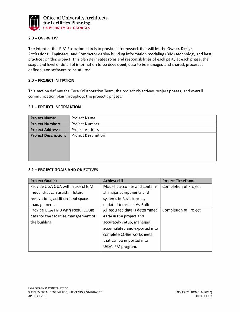
UGA DESIGN & CONSTRUCTION SUPPLEMENTAL GENERAL REQUIREMENTS & STANDARDS BIM EXECUTION PLAN (BEP) APRIL 30, 2020 00 00 10.01-3
2.0 – OVERVIEW The intent of this BIM Execution plan is to provide a framework that will let the Owner, Design Professional, Engineers, and Contractor deploy building information modeling (BIM) technology and best practices on this project. This plan delineates roles and responsibilities of each party at each phase, the scope and level of detail of information to be developed, data to be managed and shared, processes defined, and software to be utilized. 3.0 – PROJECT INITIATION This section defines the Core Collaboration Team, the project objectives, project phases, and overall communication plan throughout the project’s phases. 3.1 – PROJECT INFORMATION
Project Name: Project Name
Project Number: Project Number
Project Address: Project Address
Project Description: Project Description
3.2 – PROJECT GOALS AND OBJECTIVES
Project Goal(s) Achieved if Project Timeframe
Provide UGA OUA with a useful BIM
model that can assist in future
renovations, additions and space
management.
Model is accurate and contains
all major components and
systems in Revit format,
updated to reflect As-Built
conditions of construction
Completion of Project
Provide UGA FMD with useful COBie
data for the facilities management of
the building.
All required data is determined
early in the project and
accurately setup, managed,
accumulated and exported into
complete COBie worksheets
that can be imported into
UGA’s FM program.
Completion of Project

UGA DESIGN & CONSTRUCTION SUPPLEMENTAL GENERAL REQUIREMENTS & STANDARDS BIM EXECUTION PLAN (BEP) APRIL 30, 2020 00 00 10.01-4
3.3 – TEAM INFORMATION
Contact
Name
Role/Title Company E-mail Phone
Name title company e-mail p. 555-555-555
c. 555-555-5555
Name title company e-mail
p. 555-555-555
c. 555-555-5555
Name title company e-mail
p. 555-555-555
c. 555-555-5555
Name title company e-mail
p. 555-555-555
c. 555-555-5555
Name title company e-mail
p. 555-555-555
c. 555-555-5555
Name title company e-mail
p. 555-555-555
c. 555-555-5555
Name title company e-mail
p. 555-555-555
c. 555-555-5555
Name title company e-mail
p. 555-555-555
c. 555-555-5555
Name title company e-mail
p. 555-555-555
c. 555-555-5555
Name title company e-mail
p. 555-555-555
c. 555-555-5555
Name title company e-mail
p. 555-555-555
c. 555-555-5555

UGA DESIGN & CONSTRUCTION SUPPLEMENTAL GENERAL REQUIREMENTS & STANDARDS BIM EXECUTION PLAN (BEP) APRIL 30, 2020 00 00 10.01-5
3.4 – PROJECT PHASES / MILESTONES
Project Phase / Milestone Estimated Start
Date
Estimated
Completion Date
Project Stakeholders
Involved
Programming / Pre-Design
Phase
MM/DD/YEAR MM/DD/YEAR Owner, Design
Professional, Consulting
Engineers
Schematic Design Phase MM/DD/YEAR MM/DD/YEAR Owner, Design
Professional, Consulting
Engineers, Contractor
Preliminary Design Phase MM/DD/YEAR MM/DD/YEAR Owner, Design
Professional, Consulting
Engineers, Contractor,
Commissioning Provider
Construction Documents
Phase
(Refer to schedule for early
bid packages)
MM/DD/YEAR MM/DD/YEAR Owner, Design
Professional, Consulting
Engineers, Contractor,
Commissioning Provider
Agency Review & Bidding
Phase (Contractor)
MM/DD/YEAR MM/DD/YEAR Owner, Design
Professional, Consulting
Engineers, Contractor,
Commissioning Provider
Close-Out (Design Team) MM/DD/YEAR MM/DD/YEAR Owner, Design
Professional, Consulting
Engineers
Close-Out (Contractor) MM/DD/YEAR MM/DD/YEAR Owner, Contractor,
Commissioning Provider

UGA DESIGN & CONSTRUCTION SUPPLEMENTAL GENERAL REQUIREMENTS & STANDARDS BIM EXECUTION PLAN (BEP) APRIL 30, 2020 00 00 10.01-6
4.0 – MODEL PLANNING Identify BIM Models that will be created (ie. Design Professional, Structural, MEP, etc.), who the model managers will be from each party responsible, naming convention of BIM files that will be used for final model deliverables, and level of detail utilized at each phase. 4.1 – MODEL MANAGERS Each party—such as the Owner, Design Professional, Contractor, or Subconsultants—that is responsible for contributing modeling content should assign a model manager to the project. The model manager from each party has a number of responsibilities. They include, but are not limited to:
1. Transferring modeling content from one party to another 2. Validating the level of detail and controls as defined for each project phase 3. Validating modeling content during each phase 4. Combining or linking multiple models 5. Participating in design review and model coordination sessions 6. Communicating issues back to the internal and cross-company teams 7. Keeping file naming accurate 8. Managing version control 9. Properly storing the models in the collaborative project management system
Stakeholder
Company me
Model Manager
Name
E-mail Phone
company name name [email protected]
p. 555-555-5555
company name name [email protected]
p. 555-555-5555
company name name [email protected]
p. 555-555-5555
company name name [email protected]
p. 555-555-5555
company name name [email protected] p. 555-555-5555
company name name [email protected]
p. 555-555-5555
company name name [email protected]
p. 555-555-5555

UGA DESIGN & CONSTRUCTION SUPPLEMENTAL GENERAL REQUIREMENTS & STANDARDS BIM EXECUTION PLAN (BEP) APRIL 30, 2020 00 00 10.01-7
4.2 – PLANNED MODELS In the table below, outline the models that will be created for the project. List the model name, model content, project phase when the model will be delivered, the model’s authoring company, and the model-authoring tool that will be used. For models that will not be used or created in your project, just leave the row blank, and add rows for model types you anticipate needing that are not already listed.
Model Name Model Content Project
Phase
Authoring
Company
Authoring Tool
Design
Professional
Model
Design Professional building
and component objects, code
information, Room area
information
SD,DD, CD,
Construction,
Close-out
Design
Professional
company
name
Autodesk Revit
Design
Professional
Lab Furnishings
Model
Design Professional Casework
and Fixed Furnishings
DD, CD,
Construction,
Closeout
Consultant
company
name
Autodesk Revit
Design
Professional
Survey / Civil
Model
Topography, site utilities to
within 5 feet of perimeter,
hard and soft surfaces, other
site objects
SD, DD, CD
Construction,
Closeout
Survey
Engineer
company
name
Autodesk Civil 3D
Structural Model Structural column and beam
members, bearing and shear
walls, foundations, analytical
structural model, lintels
DD, CD,
Construction,
Close-out
Structural
Engineer
company
name
Autodesk Revit
Structure
Mechanical
Model
Mechanical systems,
equipment, load information,
utilities within 5 feet of
building perimeter, Space/
Zone objects
DD, CD,
Construction,
Closeout
Mechanical
Engineer
company
name
Autodesk Revit
MEP
Electrical Model Electrical systems,
equipment, load information,
utilities within 5 feet of
building perimeter
DD, CD,
Construction,
Closeout
Electrical
Engineer
company
name
Autodesk Revit
MEP

UGA DESIGN & CONSTRUCTION SUPPLEMENTAL GENERAL REQUIREMENTS & STANDARDS BIM EXECUTION PLAN (BEP) APRIL 30, 2020 00 00 10.01-8
Model Name Model Content Project
Phase
Authoring
Company
Authoring Tool
Plumbing Model Plumbing systems,
equipment, load information,
utilities within 5 feet of
building perimeter
DD, CD,
Construction,
Closeout
Plumbing
Engineer
company
name
Autodesk Revit
MEP
Energy Model Energy data, run iterations,
life cycle costing, peak loads
DD, CD
Company
name
??
Construction
Model
Scheduling information,
sequencing information
Fabrication models
Construction,
Closeout
Construction
company
name
Autodesk Revit,
NavisWorks
Estimate Model Costing data, quantity
takeoffs to be derived from
Design Professional’s design
intent model utilized and
further developed by
Contractor
SD, DD, CD Construction
company
name
Quantity Takeoff
and Onscreen
Take off.
Coordination
Model
Design Intent Models,
Construction Models, and
Fabrication information
Construction Design
intent
models by
Design
Taam.
Construction
and
Fabrication
models by
Construction
Team.
Autodesk
NavisWorks /
(Revit TBD)

UGA DESIGN & CONSTRUCTION SUPPLEMENTAL GENERAL REQUIREMENTS & STANDARDS BIM EXECUTION PLAN (BEP) APRIL 30, 2020 00 00 10.01-9
4.3 – BIM FILE NAMES
File Names for Models Should Be Formatted as:
DISCIPLINE-Project Number-Building Number.rvt (example: ARCH-20090001-BL001.rvt).
Design Professional
Model
ARCH-****-*****.rvt (final model name)
Lab Furnishings
Model
LABF-****-*****.rvt
Survey/Civil Model CIVL-****-*****.dwg (2010)
Structural Model STRC-****-*****.rvt
Mechanical Model MEP-****-*****.rvt (note all MEP models will be contained in a single
model) Electrical Model MEP-****-*****.rvt (note all MEP models will be contained in a single
model) Plumbing Model MEP-****-*****.rvt (note all MEP models will be contained in a single
model) Energy Model ENRG-****-*****.pd2
Construction Model CNST-****-*****.nwf / .dwg
Estimate Model COST-****-*****.rvt
Coordination Model COORD-***.*****.nwf/.nwd
4.4 – PRECISION AND DIMENSIONING Models should include all appropriate dimensioning as needed for design intent, analysis, and construction. With the exception of the exclusions listed below, the model will be considered accurate and complete. In the table below, enter which items’ placement will not be considered entirely accurate and should not be relied on for placement or assembly.
Items that Will Not Be Considered Accurate for Dimensioning or Placement
Design Professional –
Structural –
Civil –
MEP –
Lab Furnishings –

UGA DESIGN & CONSTRUCTION SUPPLEMENTAL GENERAL REQUIREMENTS & STANDARDS BIM EXECUTION PLAN (BEP) APRIL 30, 2020 00 00 10.01-10
Construction –
4.5 – MODEL ATTRIBUTE DATA / COBIE DATA PLANNING Specify model component COBie data. The Design and Construction Team will be required to add information to the BIMs that will add value to UGA’s facility management systems. In support of COBie, the Project Team is required to utilize and develop COBie schedules within the BIM model that captures data information from the model for export to COBie worksheets. The Design and Construction Team is expected to understand data requirement for all phases of the work, and should show how data capability requirements influence the planning and collaboration for this project. Diagramming and listing expected data requirements and processes, solving workflow dynamics for the collaborative team will address the intent of the BIM Project. Develop detailed component lists along with required data fields for each component to be captured and exported to COBie. Coordinate which parties on the Design and Construction Teams are responsible for delivering data at each phase of the project and how data will be consolidated and delivered so that it meets the requirements for transfer into UGA’s facilities management program. 4.6 – MODELING LEVEL OF DETAIL
Specify the level of detail in your models below. The level of detail can be defined by exclusions and/or by object size. The level of detail described here should reflect descriptions listed within the AIA E202. Size: Any object smaller than 1” will not be included in the model. Unless otherwise required to meet requirements of describing design intent and construction documentation requirements. 4.7 – MODELING PLAN AIA form E202 will be utilized as a basis for developing a detailed modeling plan. The following outlines model plan objectives at each phase. Edit and further develop the following outline as required to communicate and coordinate model development to meet the requirements and objectives of the UGA BIM Requirements and Guidelines. 4.7.1 – PRE-DESIGN / CONCEPTUALIZATION Objectives & Responsibilities: Provide initial design based on conceptual parameters established by the Owner; ensure that code and zoning requirements meet project objectives. Provide Program of Requirements and all space considerations for reference in the model. If a BIM model is established at this phase then establish a 3D reference point for future model coordination. Model Roles: Describe what kind of model will be developed and by what program. The role of this model will be to depict the visual concept and general layout of the project along with space requirements, along with other requirements as described in the UGA BIM Standards.

UGA DESIGN & CONSTRUCTION SUPPLEMENTAL GENERAL REQUIREMENTS & STANDARDS BIM EXECUTION PLAN (BEP) APRIL 30, 2020 00 00 10.01-11
4.7.2 – SCHEMATIC DESIGN PHASE Objectives: Provide spatial design based on input from the Conceptualization / Program of Requirement phase; provide initial design for building system and attributes including Design Professional, Structural, and MEP; identify initial coordination issues between building systems and 3D reference point for model coordination; if Contractor has been selected, then Contractor to receive input from suppliers and fabricators regarding system cost, placement, fabrication and scheduling. Model Role & Responsibilities: The Design Professional model will show the general design and layout of the building structure and act as the baseline for all other subsystem designs, such as MEP and Structural models. The subsystem designs are only required to be narratives at this phase. Additional information may be provided by subsystem consultants during this phase as they see fit. The Design Professional model will be used to inform the Energy Models at this phase. Address how model development will meet the requirements of the UGA BIM Requirements and Guidelines. COBie Data: Establish schedules and project parameters in the BIM model that will become the basis for exporting model data to COBie worksheets. Submit initial COBie data worksheets as describing in the UGA BIM Requirements and Guidelines.
4.7.3 – PRELIMINARY DESIGN (DESIGN DEVELOPMENT) Objectives: Provide developed design of building and building systems; resolve coordination issues between building systems; if a Contractor is on board at this phase of the project then a combined (Design Professional/Structural/MEP) Design Intent Model(s) will be provided to the Contractor for use in his development of a Construction Model capable of analyzing schedule, cost, and constructability. Model Roles & Responsibilities: The Design Professional model will continue to act as the baseline for all other subsystem designs. The subsystem designs will be modified accordingly to represent the enhanced design. Once the baseline conceptual structure has been created, the Design Professional’s model manager will send the model to the Subconsultants so they can develop their designs. The Consulting Engineers’ designated model managers will audit and deliver the completed models to the Design Professional’s model manager. The Design Professional’s model manager will review the models to ensure compliance with the phase requirements. Once the models meet the requirements, the Design Professional’s model manager will link or combine cross-disciplinary models. The Design Professional’s model manager should coordinate with the Consulting Engineers’ model managers to eliminate duplicate or redundant objects. The Consulting Engineers’ model managers will use the Design Professional model to revise and complete their designs. Once the models are complete, the Consulting Engineers’ model managers will deliver their models to the Design Professional’s model manager. The Design Professional’s model manager will review the models to ensure compliance with the phase requirements. The Design Professional’s model manager will provide the Contractor’s model manager with the Design Professional model and the Consulting Engineers’ models. Elements or Components that will need to be duplicated between models will be documented and coordinated and a system developed for controlling the display of duplicate elements will be established through the use of work sets or other mutually agreed upon process.

UGA DESIGN & CONSTRUCTION SUPPLEMENTAL GENERAL REQUIREMENTS & STANDARDS BIM EXECUTION PLAN (BEP) APRIL 30, 2020 00 00 10.01-12
COBie Data: Submit updated and additional COBie data worksheets as describing in the UGA BIM Requirements and Guidelines. 4.7.4 – CONSTRUCTION DOCUMENTS (CONTRACT DOCUMENTS) Objectives: Finalize design of the building and all building systems, prepare documentation for agency review, and provide Design Intent Models that are the basis for all Contract Document Drawings, including all plans, elevations, sections, schedules and details needed for use in the construction of the project. Provide the Contractor a combined (Design Professional/Structural/MEP) Design Intent Model(s) that will be utilized in his development of a Construction Model capable of analyzing schedule, cost, phasing and constructability. Model Roles & Responsibilities: All Design Intent Models will be used to reflect the design intent of the project and be the basis for all Contract Document Drawings, these models will become the basis for creating and updating the Record Models and Record Drawings. These models will then be used as the basis for generating the Construction Model(s). The Construction Model will be used for estimating, scheduling, phasing, and constructability analysis. The Construction Model(s) will also become the basis for future development of element and component data needed for the development and gathering of COBie data for periodic export into COBie worksheets. COBie Data: Submit updated and additional COBie data worksheets as describing in the UGA BIM Requirements and Guidelines. Establish a schedule for future periodic COBie data worksheet updates to occur during the construction phase, along with final worksheet delivery at closeout. 4.7.5 – BIDDING PHASE Objective: Revise Design Intent models based on agency feedback on all models. Incorporate feedback into Addenda. Design Team to update all Design Intent Models with Addenda as issued. Model Roles & Responsibilities: The Design Intent Models will be adjusted to reflect agency feedback. The Construction Model will be enhanced and further used for estimating, scheduling, construction sequencing, trade coordination, and constructability analysis. The Design Professional’s model manager will communicate agency comments back to the Design Team. The Consulting Engineers’ model managers will revise their design models accordingly and submit them back to the Design Professional. The Design Professional’s model manager will provide the Contractor’s model manager with the Design Professional model and the Consulting Engineers’ models. COBie Data: No COBie data requirements at this phase. 4.7.6 – CONSTRUCTION PHASE Objective: Update Design Professional and Consulting Engineers’ models based on submittals, RFIs, or owner-directed changes; maintain the Construction Model based on construction activities. The Construction Team will submit RFIs and submittals through the collaborative project management system.

UGA DESIGN & CONSTRUCTION SUPPLEMENTAL GENERAL REQUIREMENTS & STANDARDS BIM EXECUTION PLAN (BEP) APRIL 30, 2020 00 00 10.01-13
Model Roles & Responsibilities: The Design Professional and Consulting Engineers’ Design Intent Models will be revised throughout construction, based on owner directives and As-Built comments. The models will always reflect the revised contract documents with the exception of those items listed as excluded in this BEP. The Construction Model will be used for scheduling analysis, construction sequencing, delegated design component development and trade coordination. Establish and document any departures from concurrent modeling between Design Intent and Construction Models, for example, it may be desirable to maintain the original Design Intent Model as a record of the originally designed mechanical system as designed by the Mechanical Engineers as a reference point for evaluating and comparing any re-designed mechanical systems made by the Mechanical Subcontractor as a result of delegated design responsibilities. The Design Professional’s model manager will work with their Consulting Engineers to answer the RFIs and submittals and adjust the models accordingly. The Contractor’s model manager will update the Construction Model and will work with the Design Professional to develop the Design Professional and Consulting Engineers’ models. COBie Data: Submit updated and additional COBie data worksheets as describing in the UGA BIM Requirements and Guidelines. Establish a schedule for periodic COBie data worksheet updates to occur during the construction phase, along with final worksheet delivery at closeout. Establish a plan for consolidating COBie data that will be exported and generated by multiple models potentially, with multiple party responsibilities that will be acceptable and useable by the Owner’s end-user parties. 4.7.7 – CLOSE-OUT (DESIGN TEAM) Objective: Use the Design Professional and Consulting Engineers’ Design Intent Models for facility management, with the possibility of use in ongoing operations for future additions, renovations, etc. Model Roles & Responsibilities: The Design Professional and Consulting Engineers’ models will be used to represent the actual assembly of the building from construction with the exception of those items listed as excluded in this BEP. If Construction Models are more representative than Design Intent models of actual As-Built components such as mechanical System, then formulate a plan for combining differing models. The Design Professional will deliver the Record Design Intent Model(s) and Record Drawings at the end of the project to the Owner. COBie Data: The Design Team will coordinate with the Construction Team to deliver a coordinated and consolidated COBie worksheet deliverable at closeout. 4.7.8 – CLOSE-OUT (CONSTRUCTION TEAM) Objective: Use the Contractors Construction Model(s) as the basis for all final component data derived from shop drawing submittal process needed for UGA Physical Plant operations and facilities management. Model Roles & Responsibilities: The Contractor’s models will be used to represent the actual assembly of the building from construction, and will be utilized in generating the final As-Built Model and Documents. It will also be used as the basis of COBie data associated with actual product selection as the result of the shop drawing and submittal processes. The Contractor will deliver the As-Built Construction Model(s) and As-Built Documents at the end of the project to the Owner.

UGA DESIGN & CONSTRUCTION SUPPLEMENTAL GENERAL REQUIREMENTS & STANDARDS BIM EXECUTION PLAN (BEP) APRIL 30, 2020 00 00 10.01-14
COBie Data: The Design Team will coordinate with the Construction Team to deliver a coordinated and consolidated COBie worksheet deliverable at closeout.

UGA DESIGN & CONSTRUCTION SUPPLEMENTAL GENERAL REQUIREMENTS & STANDARDS AESTHETIC AUTHORITY APRIL 30, 2020 00 00 11-1
00 00 11 AESTHETIC AUTHORITY
1. GENERAL
A. Aesthetic opinions and evaluations by a Design Professional are advisory only – and not binding on UGA. The OUA reserves the right for final aesthetic judgment.

UGA DESIGN & CONSTRUCTION SUPPLEMENTAL GENERAL REQUIREMENTS & STANDARDS CLIENT & END USER INTERFACE APRIL 30, 2020 00 00 12-1
00 00 12 CLIENT & END USER INTERFACE
For Projects Administered by the OUA or FMD
1. GENERAL A. The Design Professional and Contractor shall take directions that modify the scope of
work only from the Owner’s Representative. The person or entity that will occupy the Project is not authorized to modify the scope of work. For projects administered by OUA, the FMD is not authorized to modify the scope of work. For projects administered by FMD, the OUA is not authorized to modify the scope of work.

UGA DESIGN & CONSTRUCTION SUPPLEMENTAL GENERAL REQUIREMENTS & STANDARDS DESIGNING LEARNING ENVIRONMENTS APRIL 30, 2020 00 00 13-1
00 00 13 DESIGNING LEARNING ENVIRONMENTS
1. GENERAL
A. Related sections: i. 09 00 00 – General Finishes Requirements
ii. 09 80 00 – Acoustical Treatment iii. 11 52 00 – Audio Visual Equipment iv. 11 52 13 – Projector Screens v. 12 00 00 – General Furnishings Requirements
vi. 12 46 33 – Interior Waste Receptacles vii. 12 56 52 – Audio-Visual Furniture
viii. 22 00 00 – General Plumbing Requirements ix. 23 00 00 – General Mechanical Requirements (HVAC) x. 26 00 00 – General Electrical Requirements
xi. 26 51 00 – Interior Lighting xii. 27 00 00 – General Communications Requirements
xiii. 27 41 00 – General Audio-Visual Systems Requirements xiv. 27 41 00.01 – Audio-Visual Control System
Table of Contents 1.0 – Foreword 03 2.0 – Background & Scope 04 3.0 – General Considerations 08
3.1 – New Construction vs. Renovation 08 3.2 – Goals 08
4.0 – Classroom General Design Criteria 09
4.1 – Location 09 4.2 – Size & Proportion 09 4.3 – Sight Lines & Viewing Angles 11 4.4 – Seat Spacing 12 4.5 – Doors & Windows 12 4.6 – Finishes 13 4.7 – Furniture & Equipment 13 4.8 – Acoustics 14 4.9 – Accessibility 17 4.10 – Audiovisual Systems 17 4.11 – Lighting / Electrical Systems 18 4.12 – Building Systems 18
5.0 – General Purpose Flat Classrooms 19 5.1 – 10 to 20 Seat Lecture, Seminar, Conference, & Active Learning Classrooms 19

UGA DESIGN & CONSTRUCTION SUPPLEMENTAL GENERAL REQUIREMENTS & STANDARDS DESIGNING LEARNING ENVIRONMENTS APRIL 30, 2020 00 00 13-2
5.2 – 20 to 49 Seat Lecture & Active Learning Classrooms 23 5.3 – 50 to 60 Seat Lecture & Active Learning Classrooms 26 5.4 – 60 to 100 Seat Lecture & Active Learning Classrooms 31
6.0 – General Purpose Tiered Classrooms 35 6.1 – 100 to 120 Seat Lecture / Collaborative Classrooms
35 6.2 – 200 to 280 Seat Lecture Hall 39
7.0 – SCALE-UP Classrooms 42
7.1 – 45 Seat Classroom 43 7.2 – 72 Seat Classroom 44 7.3 – 99 Seat Classroom 45
8.0 – Classroom Design Quick Checklist 46

UGA DESIGN & CONSTRUCTION SUPPLEMENTAL GENERAL REQUIREMENTS & STANDARDS DESIGNING LEARNING ENVIRONMENTS APRIL 30, 2020 00 00 13-3
1.0 - FOREWORD Building and adapting learning spaces to support the continuing change of pedagogy and technology at the University of Georgia (UGA) provides many challenges; however, there are a number of evidence-based reasons to pursue excellence in learning space design. Research has shown that active learning techniques provide clear improvements in learning1, but a majority of the current teaching spaces at UGA don’t easily lend themselves to support these pedagogies. The Georgia Board of Regents has long supported the creation of classrooms with a standard level of quality that includes a “flexibility to respond to future requirements.”2 One of the operative goals is “to develop and implement a well-conceived and consistent concept for how technology requirements can best be accommodated in designing new and renovated facilities.”2 A lack of compliance to these minimum standards creates a clear challenge to effective learning according to research.3 It is vital that all classrooms have appropriate furniture, correctly maintained classroom technology, and proper physical design and maintenance. All of these have been shown to have a direct effect on learning outcomes 3 and student success.
This document has been a joint effort between the UGA Office of University Architects and the Center for Teaching and Learning to provide relevant standards and guidelines for the design and construction of new classroom space and the renovation and maintenance of existing spaces. Outside consultants have been included in this process to ensure that current best practices in the fields of architecture, design, construction, and technology have been brought together with the current research regarding teaching and learning. The result provides clear direction for the effective design and development of learning environments at UGA.
1 Summary of Key Papers on Efficacy of Active Learning (2012). http://cst.yale.edu/sites/default/files/active learning bibliography.pdf 2 Facilities Guidelines For Instructional Technology (2001).
http://www.usg.edu/facilities/documents/facilities_it_guidelines.pdf 3 Making the Case for Space: Three Years of Empirical Research on Learning Environments (2010)
http://www.educause.edu/ero/article/making-case-space-three-years-empirical-research-learning-environments
Space Matters: The Impact of Formal Learning Environments on Student Learning (2010) https://www.bgsu.edu/content/dam/BGSU/master-plan/documents/space-matters.pdf
Minimum Classroom Size and Number of Students Per Classroom (2000/2009) http://sdpl.coe.uga.edu/research/territoriality.html

UGA DESIGN & CONSTRUCTION SUPPLEMENTAL GENERAL REQUIREMENTS & STANDARDS DESIGNING LEARNING ENVIRONMENTS APRIL 30, 2020 00 00 13-4
2.0 – BACKGROUND & SCOPE With the University of Georgia’s continuing development of educational pedagogy, it is clear that new design requirements and best practices are needed. This section is to be referenced during the design of learning environments at the UGA to ensure that all classrooms are consistent with current teaching practices. The considerations highlighted should be part of the design conversation at the earliest stages of both new construction and renovation projects. The UGA understands the design of each individual project is a unique and dynamic process, in which the project has specific goals and needs. These specifics may not be covered in the guidelines; however, the intent of the learning environment should be honored. The Design Professional is to communicate with UGA regularly about the quality of project specific learning environments, and any questions should be directed to the Project Manager. If there is a valid reason to deviate from the Standards, the Design Professional shall submit a Variance form per Section 00 00 05 Variance Requirement & Form. To fully capitalize on the benefits of the University’s educational pedagogy and availability new technologies, learning environments should strive to not be static physical spaces which support only one-way transmission of information. This idea should not be limited to new learning environments, but should also be upheld during renovation of existing spaces. This section outlines requirements and best practices for the following classroom types:
1. 10 to 20 seat flat lecture, seminar, conference, and active learning classrooms.

UGA DESIGN & CONSTRUCTION SUPPLEMENTAL GENERAL REQUIREMENTS & STANDARDS DESIGNING LEARNING ENVIRONMENTS APRIL 30, 2020 00 00 13-5
2. 20 to 49 seat flat lecture and active learning classrooms.
3. 50 to 60 seat flat lecture and active learning classrooms.

UGA DESIGN & CONSTRUCTION SUPPLEMENTAL GENERAL REQUIREMENTS & STANDARDS DESIGNING LEARNING ENVIRONMENTS APRIL 30, 2020 00 00 13-6
4. 60 to 100 seat flat lecture and active learning classrooms.
5. 100 to 120 seat tiered collaborative lecture classrooms.

UGA DESIGN & CONSTRUCTION SUPPLEMENTAL GENERAL REQUIREMENTS & STANDARDS DESIGNING LEARNING ENVIRONMENTS APRIL 30, 2020 00 00 13-7
6. 200 to 280 seat tiered collaborative lecture, and traditional lecture halls.
7. 45, 72, and 99 seat SCALE-UP classrooms.

UGA DESIGN & CONSTRUCTION SUPPLEMENTAL GENERAL REQUIREMENTS & STANDARDS DESIGNING LEARNING ENVIRONMENTS APRIL 30, 2020 00 00 13-8
3.0 – GENERAL CONSIDERATIONS 3.1 – New Construction vs. Renovation There are a variety of ways that instructors teach and students learn, and there is a wide range of ways that those interactions manifest in the physical environment. Spaces that were once considered appropriate for a certain classroom sizes and teaching styles may no longer be appropriate. In these situations, special considerations must be taken during the renovation of existing classrooms. The Design Professional must be in communication with UGA to determine the best use for existing spaces to support the current instruction methodology. Renovations to existing learning environments should hold true to the intent of the classroom design guidelines. 3.2 – Goals The goal of the Design Professional is to provide learning environments in which the values inherent in traditional instruction are upheld, but easily adapt to allow collaborative learning scenarios. The classroom should be easily adaptable to enable new opportunities and universal access. The following goals4 should be addressed during the design of learning environments:
1) Flexibility 2) Accessibility 3) Life Cycle 4) Cost Benefit
The flexibility of classrooms is encouraged so that a variety of learning scenarios may take place in each classroom, as required by the end user. When necessary, multiple furniture layout scenarios may be considered in the overall design of the classroom. Additionally, the flexibility of the systems provided in the classroom may be necessary for students to access instructional courses via alternative modes of delivery. The required flexibility of the classroom will inform the adaptability and scalability of the furniture and systems provided in the instructional space. Learning environments should not only be physically accessible (so that they conform to ADA requirements), but should also be technologically accessible to all students and instructors. Equipment, furniture, and other technology must be easily accessed and manipulated by end users. The typical life cycle of finishes, furniture, and equipment should be considered during the design of learning environments, as they relate to the overall operational life cycle of the building in which it resides. The selection and location of classroom elements should meet requirements outlined in the UGA Design and Construction Standards, as well as allow for easy maintenance and replacement within each classroom. Cost benefit analysis must always be taken into consideration during the design of learning environments. The guideline outlines considerations to be taken during the design of classrooms;
4 The goals outlined are adapted from the Board of Regents of the University System of Georgia’s Facilities Guidelines for Instructional Technology, 2001.

UGA DESIGN & CONSTRUCTION SUPPLEMENTAL GENERAL REQUIREMENTS & STANDARDS DESIGNING LEARNING ENVIRONMENTS APRIL 30, 2020 00 00 13-9
however, the extent to which best practices are followed should be determined on a case-by-case basis. The Design Professional should determine if certain recommendations are the most cost efficient solution for each instructional space, or if other options are available that meet the intent of the guideline. 4.0 – CLASSROOM GENERAL DESIGN CRITERIA This portion outlines necessary design characteristics that must be considered during the design of learning environments. The scale of considerations varies from the location of specific classroom within an overall building to providing finish protection in high traffic areas. All considerations intend to help each classroom perform at a high level for UGA. 4.1 – LOCATION Classroom spaces shall be located as close as possible to building entrances and level accesses to improve circulation and reduce noise levels in other parts of the building. Large classrooms shall be located close to primary building entrances. Circulation spaces which support large classrooms should be sized so that they accommodate students waiting in the hallway for the next class session. It may be desirable for smaller classrooms to be located closer to offices and / or related lab spaces. The location of small classrooms should be discussed with end users to determine special requirements for circulation spaces and programmatic adjacencies. When possible, classrooms should be separated from noise generating areas such as mechanical rooms, elevators, vending areas, and restrooms. When separation from these functional areas is not possible, ensure that adequate noise separation is provided. Please refer to the Acoustics Section 4.8 of this guideline. The location of certain classrooms in relation to their solar orientation impacts their access to natural daylight considerably. The Design Professional should discuss with the end user whether natural daylighting is beneficial or should be avoided (i.e. easily controlled). Classrooms with northern exposure may be more easily designed to provide comfortable natural daylighting capabilities while not adversely impacting AV systems, as well as be more energy-efficiency than rooms with windows facing other cardinal directions. Passive solar design features should be considered for rooms where windows face south, east, and west. 4.2 – SIZE & PROPORTION Classrooms must be designed so that they comfortably accommodate the number of students planned for each classroom type, as well as the types and sizes of furnishings anticipated to be used in the space. The UGA Center for Teaching and Learning shall be involved in any discussions that concern classroom functions and / or seating capacities. The Design Professional shall coordinate with the Project Manager to assist with including the UGA Center for Teaching and Learning in design meetings. The following space standards and furnishing types shall be used to estimate the total usable floor area of classrooms during the programming phase of a project:

UGA DESIGN & CONSTRUCTION SUPPLEMENTAL GENERAL REQUIREMENTS & STANDARDS DESIGNING LEARNING ENVIRONMENTS APRIL 30, 2020 00 00 13-10
SF Per Student Room Type Capacity Anticipated Furnishings
30-52 Small Classrooms: Lecture, Seminar, Conference, and
Active Learning
10-20 Moveable tables and chairs
27-31 25-29
Medium Classrooms: Lecture, and Active Learning
20-49 50-60
Moveable tables and chairs
20-25 Large Classrooms: Lecture, and Active Learning
60-100 Moveable tables and chairs
20-22 15-18
Tiered Classrooms: Collaborative, and
Traditional Lecture Hall
100-120 200-280
Fixed tables and movable Chairs Traditional Lecture Hall – Tablet arms acceptable
21 21 19
SCALE-UP Classrooms 45 72 99
Fixed tables and movable chairs.
The Design Professional shall develop applicable classroom furnishing layouts during the schematic design phase to verify that the proposed classroom sizes and shapes successfully accommodate the number of students programmed for each space. Classroom proportions have a considerable impact on seating capacity, sight lines, and instructor / student interaction. There are no set required proportioned for classrooms; however, the Design Professional should keep these common issues in mind during the design process: Classrooms that are too wide make it difficult for instructors to maintain eye contact and typically have poor sightlines. This issue is especially significant for students located in the front corners of the space. Instructor areas are often deeper than necessary in order to avoid this issue. This is not typically an issue for non-traditional style classrooms, i.e. SCALE-UP classrooms.
Classrooms that are too deep make it difficult for students in rear rows hear what is said, see projected images, and see notes on markerboards. Special consideration must be taken into account for the acoustics of large classrooms to ensure that students are able to hear all necessary instruction. Additionally, projected images must be adequately sized so that all students are able to see classroom instructional information.
Highly adaptable small classroom, which accommodate seminar classes, should avoid long rectangular proportions. Elongated proportions for this instruction type inhibit eye contact between students and instructors, and diminish the view angles of classroom participants to projected information. To encourage interactive discussion while providing good sight lines, rooms that are nearly square or have a shape based on viewing angles from projection screens / flat-panel monitors are the most successful and adaptable for all small classrooms instruction type.
When walls are the first items laid out in classrooms, and subsequently furniture layouts are tested; it is difficult to verify that students have quality sight lines and instructor areas are adequately sized. The following are recommendations for developing classrooms with good sight lines and efficient seating layouts:

UGA DESIGN & CONSTRUCTION SUPPLEMENTAL GENERAL REQUIREMENTS & STANDARDS DESIGNING LEARNING ENVIRONMENTS APRIL 30, 2020 00 00 13-11
1) Determine number of screens based on seating capacity and classroom type. 2) Determine the general location, size, and orientation of each screen based on the seating
area. 3) Determine the location and size of the instructor area based upon the required
markerboards, projection screens, and other equipment necessary for the classroom type. 4) Make certain the instructor area is large enough to accommodate the instructor
workstation, required equipment, and ample circulation around workstation, markerboard, and seating. Ensure that the instructor station is not directly in the light path of a front-screen projector.
5) Determine optimum width and depth of the seating area based on seat spacing guidelines, provided in each of the typical classroom layout sections.
6) Determine the location and size of access aisles. 7) Draw viewing angles from each screen and make certain all seats provided fall within them. 8) Finally, determine where the walls of the classroom should be located.
4.3 – Sight Lines & Viewing Angles The Design Professional should provide recommendations for existing ceiling height. If the existing ceiling height does not work, the Design Professional should notify the Project Manager to resolve concerns. The Design Professional is responsible for coordinating with the Audio-Visual Consultant to ensure all seats have good sight lines. If any seats have marginal sight lines, the Design Professional must bring this to the attention of the Project Manager. The size of the projected image should follow current industry standards. The farthest viewer should be placed no further than five times the height of the screen. Example: if the screen is six feet tall, the farthest viewer should be no further than 30 feet from the screen. The closest viewer should be no closer than one and a half times the width of the screen. Example: if the screen is six feet wide, the first viewer should be no closer than nine feet from the screen. In flat floor classrooms, the bottom of the projected image is recommended to be a minimum of 48” above the finished floor (AFF); however, 54” AFF is preferred. The Design Professional should keep in mind that combining the 5H screen sizing factor with the 48” AFF image requirement will have a significant impact on the ceiling height of larger learning spaces. Strategies such as favoring wider rooms over deeper rooms (thus reducing the distance to the farthest viewer) and / or routing ductwork around the front-center area of the room such that the ceiling elevation can be raised in the projection screen area should be considered. SCALE-UP classrooms shall have smaller sized projection screens which are located on multiple walls of the classrooms between groups of tables to allow students to see content without having to rotate their seats away from their work surface. 4.4 – Seat Spacing

UGA DESIGN & CONSTRUCTION SUPPLEMENTAL GENERAL REQUIREMENTS & STANDARDS DESIGNING LEARNING ENVIRONMENTS APRIL 30, 2020 00 00 13-12
Student Seating Scenario Minimum Chair Spacing (Inches) On Center (O.C.)
Moveable Chairs at Movable Desk 30” O.C.
Movable Chairs at Fixed Desk 28” O.C.
Fixed Chairs w/ Tablet Arms* 24” O.C.
*Center for Teaching and Learning shall be notified of intent to have fixed seats and approve application as early as possible in the design phase and prior to completion of schematic design. Fixed tables with movable chairs are provided in larger collaborative tiered classrooms. Seating should be spaced a minimum of 28” on center. Continuous work surfaces should be a minimum of 18” deep, and should be equipped with modesty panels. Provide 36” clear between work surfaces in rows up to 20 seats. Consider providing 38” clear in rows with more than 21 seats. To ensure that students have adequate knee clearance in the collaborative fixed table scenario, the work surface in the rear of the grouping should have a 4” to 6” overhang. Fixed chairs with tablet arms are only acceptable in large tiered lecture halls with 200-280 seats. The minimum seat spacing in this scenario is 24” on center. A minimum of 12” clear is to be provided between edge of the tablet arm (when in use) and back of seat in front. When classrooms have tiered seating, and their occupancy is large enough that they are considered assembly areas, additional consideration must be given to aisle clear dimensions. Aisles and handrails provided in assembly areas should be sized and located to conform to building and fire codes. 4.5 – Doors & Windows Classroom entry doors with visual connection to corridors should be used whenever possible. Visual connection may be achieved by providing glass sidelights or vision panel within the door itself. In small classrooms, where only one entry is provided, doors should be located away from the instructor to avoid bottlenecking at door. In large classrooms, locate doors so that students entering class late minimally distract from instruction. In classrooms where lights are dimmed, light may seep in from corridors, which could diminish the contrast ratio of projected information. Doors should be located to reduce the impact of light entering from corridors. In larger tiered classrooms, it may be helpful to locate entry doors at the rear of the classroom or within entry vestibules to help minimize light spillover from the hallway. Transoms are encouraged above doors to increase natural daylight into corridors. Care should be taken to ensure that direct sunlight is kept off of projection screens and / or that transoms are provided with proper shading controls. Special consideration must be taken in locating windows in classrooms spaces. Instructor areas should not be located along window walls. Certain instructional classroom types necessitate locating

UGA DESIGN & CONSTRUCTION SUPPLEMENTAL GENERAL REQUIREMENTS & STANDARDS DESIGNING LEARNING ENVIRONMENTS APRIL 30, 2020 00 00 13-13
markerboards and projection surfaces on a majority, if not all, of the classroom walls. When this is a possibility, windows are most conveniently located above and / or below markerboard space. When it is not possible to locate windows in this fashion, the Design Professional should strategize how to provide adequate collaborative equipment without conflicting with window locations. Certain classroom types require blackout capabilities, especially distance learning classrooms. Locate these classrooms accordingly within the building. If windows are provided in these spaces, ensure that adequate window shading is provided. 4.6 – FINISHES Refer to Section 09 00 00 General Finishes Requirements. 4.7 – FURNITURE & EQUIPMENT Refer to Section 12 00 00 General Furnishings Requirements. Instructor Area A minimum of 8’ clear space parallel to the instructor wall (10’ preferred) shall be provided in small and large lecture style classroom layouts. Instructor areas are to accommodate computer-based audio-visual systems. Provide floor and / or wall junction boxes for power / data / audiovisual systems wiring to serve the workstation. The floor junction box should be a minimum of 5 feet from the front wall in small classrooms and a minimum of 6 feet from the front wall in large classrooms. Instructor areas are to accommodate instructors who are standing, seated, or using wheelchairs. Workstation features and location considerations:
1) Workstations should be oriented to maximize eye contact between instructor and students, while allowing students to see projected media.
2) In rooms with one screen, an instructor workstation on the left side of the instructor area, markerboards in the center, and a screen in the right corner is preferred.
3) In large rooms with multiple screens, a workstation located on the left side of the instructor area, near the markerboard, usually works well, but a more central location may be preferable.
4) Provide adequate circulation space around lectern and surrounding equipment / furniture. The minimum clear dimension is 36”; however, 48” is preferred. For larger spaces, 48” is a minimum distance from the front wall.
5) The type / size of the lectern is to be determined by the classroom type. Refer to Section 12 56 52 Audio-Visual Furniture for listing of recommended lectern types and sizes.
Additional Considerations: Consider providing an additional small table within instructor area in large lecture classrooms for disbursement and collection of classroom handouts. Should additional tables and / or equipment (i.e. demonstration table) be required and located within instructor area, include these items in preliminary classroom layout. Carefully locate the required equipment and j-boxes in the instructor area so that tripping hazards are avoided.

UGA DESIGN & CONSTRUCTION SUPPLEMENTAL GENERAL REQUIREMENTS & STANDARDS DESIGNING LEARNING ENVIRONMENTS APRIL 30, 2020 00 00 13-14
Student Seating Refer to Section 12 00 00 General Furnishings Requirements. This section also includes minimum chair spacing information which is critical when initialing laying out classrooms. Interior Waste Receptacles The designer should plan for efficiently sized waste receptacles near exit doors in locations that do not obstruct other room functions. Refer to Section 12 46 33 Interior Waste Receptacles. Provide a large clock that is easy to read and can be seen by instructors and students. Audio-Visual Furniture Using similar lecterns from classroom to classroom simplifies instructor equipment training, and makes classrooms more technologically accessible. Refer to Section 12 56 52 Audio-Visual Furniture. 4.8 – ACOUSTICS Numerous studies over the past several decades have concluded that transmission of the spoken word from talker to listener is of primary importance in any learning environment to enhance learning, minimize listener fatigue, promote the retention of information, and reduce distractions from unwanted noises. As learning pedagogies evolve from traditional models (i.e. a one-to-many delivery paradigm) to more active model (e.g. group discussion / interaction), the transmission of intelligible speech within the room and the overall behavior of a space acoustically becomes even more critical. Additionally, the current trend in architecture towards less “soft goods” in a space (i.e. concrete floors, exposed concrete or metal deck ceilings, etc.), whether to meet sustainability goals or to meet a design aesthetic, can often run counter to a classroom’s acoustical needs and primary functional intent. To address the successful transmission of intelligible speech – whether from instructor to student, student to instructor, or student to student – three separate but related acoustical areas of concern must be addressed:
1) Room acoustics pertaining to surface finishes and room geometry 2) Background noise levels, primarily HVAC systems and 3) Sound isolation from exterior noise intrusion (i.e. from adjacent rooms and lobbies / corridors,
as well as outside noise from traffic, cooling towers, transformers, etc.) If all three of these areas are properly addressed, the dependence on speech reinforcement systems (i.e. lavaliere microphones, digital mixers, etc.) can be eliminated for all but the largest lecture halls. Eliminating speech reinforcement would result in lower initial project costs, as well as simpler operations and maintenance for the entire lifecycle of the classroom. Thus, the Design Professional should consider acoustics a primary design consideration for all learning spaces. Below is an overview of each of the three areas of concern and design criteria and strategies for each:

UGA DESIGN & CONSTRUCTION SUPPLEMENTAL GENERAL REQUIREMENTS & STANDARDS DESIGNING LEARNING ENVIRONMENTS APRIL 30, 2020 00 00 13-15
Room Acoustics Room finishes have the most dramatic impact on the intelligible transmission of speech within most classrooms, as well as the management of the overall noise level in a classroom for active learning spaces where multiple group discussions may be occurring simultaneously.
In general, classrooms and lecture halls should be designed to distribute sound absorbing materials among the major surfaces in the space (floor, ceiling and walls) while balancing other major design considerations such as durability, aesthetics, daylighting and cost. Reverberation times for classrooms should be targeted to meet an RT-60 criteria (i.e. the time it takes for sound to dissipate by 60 decibels) of less than 1 second for most classrooms and closer to 0.6 seconds for distance learning classroom.
A general strategy to achieve this reverberation time for these major surfaces is as follows:
Floors For durability, hard-finish floors may be preferred. Where possible, low-pile carpeting is recommended classroom floor surface area to mainly reduce foot-fall traffic noise and introduce sound absorption to this major surface area, especially for distance learning spaces. Ceiling Acoustical ceiling tile with a noise reduction coefficient (NRC) of at least 0.70 should be at least 50% of the ceiling area for small rooms (10-20 occupants) and as much as 80% to 100% for large rooms (20 – 60 occupants). Rooms with a capacity of 100 or more occupants should use acoustical ceiling tile with a NRC rating of 0.90 over at least 80% of the ceiling area. As a strategy to promote the reflection of speech energy between instructors and students, the Design Professional can consider introducing some reflective ceiling elements (lay-in reflective panels or gypsum-board areas) in strategic locations in the ceiling area in balance with the absorptive areas around the perimeter. Walls Lastly, durable / tackable acoustical wall panels (with 1” thick fiberglass backing behind an acoustical transparent covering) should be considered for at least 25 percent of the room’s wall area. Larger volume spaces are naturally more inclined to result in higher reverberation times. Thus, as rooms get larger, it is increasingly important to control reverberation and echoes (from large area, hard, parallel surfaces) through the use of absorptive room finishes such as acoustical wall panels. Since many rooms contain parallel walls, it is often advisable to apply acoustical wall finishes to adjacent surfaces to address the flutter echoes from these parallel surfaces. Alternately, walls can be designed to be non-parallel to reduce the need for absorptive wall materials. Background Noise Levels

UGA DESIGN & CONSTRUCTION SUPPLEMENTAL GENERAL REQUIREMENTS & STANDARDS DESIGNING LEARNING ENVIRONMENTS APRIL 30, 2020 00 00 13-16
To achieve a proper signal-to-noise ratio in a classroom (where the signal is the spoken word and the noise is the background noise level) the Design Professional must consider the design of the HVAC system (which is the primary contributor to background noise) as part of the acoustical environment of the classroom. Per ASHRAE guidelines classrooms should be designed to meet a background noise criterion of NC-30. Special purpose classrooms (e.g. distance learning, music classrooms, screening rooms, etc.) may require even lower background noise levels. To achieve appropriate background noise levels, classrooms should be designed to be acoustically separated by physical distance and / or enhanced partition design (see the section to follow on sound isolation) from noisy mechanical rooms and primary duct runs. Noise-inducing HVAC equipment such as fan-coil units and VAV boxes should be positioned outside of the classroom envelope (usually outside the room over the hallways) and duct runs should be calculated to be long enough to reduce noise levels at any diffuser to be at least five points below the overall room criteria. Use of duct silencers is to be avoided and used as a last resort. The Design Professional shall discuss the specification of duct silencers with UGA prior to including them in the design. The need for duct silencers shall be supported by calculations to be submitted for review by UGA and Commissioning Provider. Duct cross-sections shall be increased to minimize system pressure drop where duct silencers are the only alternative to achieve desired noise levels. Equipment with the lowest noise signature should be selected, and duct work shall be laid out in such a way that attenuation is maximized. Sound Isolation Another contributor to acoustical distractions which can hamper a student’s ability to maintain focus / attention in a classroom setting is the intrusion of unwanted, outside noise into the classroom. This intrusion can come from adjacent spaces (both vertically and horizontally adjacent), as well as from outside the building (cars, trains, mechanical equipment, etc.). The first, and often easiest and cheapest, sound isolation strategy is to architecturally isolate noisy spaces, such as main mechanical rooms, from noise-sensitive spaces, like classrooms, early in the design process. When physical separation is not possible, enhanced acoustical wall, floor and ceiling constructions must be considered as the next line of defense. Walls between adjacent classrooms should go to structure and have a sound transmission class (STC) rating of at least STC-45. Walls with STC ratings of 50 to 55 should be used between classrooms equipped with sound systems. Typical classroom doors should be STC-30 or more, while noisier classroom types (i.e. music rooms) should have doors with STC-40 or more. With studies showing that some amount of daylight helps to enhance student attention, special consideration should be taken to weigh the benefits of day lit classrooms with the potential distraction from the noise intrusion through the glass. There are many high-STC glazing solutions available, but these solutions can often increase material costs significantly. Recommendations5 for classroom walls’ sound transmission class (STC):
Adjacent Space Sound Transmission Class Rating
5 Recommendations based on the American National Standards Institute (ANSI) Section 12.6-2002

UGA DESIGN & CONSTRUCTION SUPPLEMENTAL GENERAL REQUIREMENTS & STANDARDS DESIGNING LEARNING ENVIRONMENTS APRIL 30, 2020 00 00 13-17
Corridor, classroom (non-audio equipped), stair case, office, or conference room
STC-45
Classroom (audio equipped), learning clinic, break out space, or outdoors
STC-50-55
Restroom STC-53
Music room, mechanical room, dining area, gymnasium, or natatorium
STC-60
Acoustics Summary The acoustics guidelines and strategies noted above are very general in nature and are intended as a basic starting point for design. Each project has its own unique acoustics conditions that require analysis. It is recommended that the Design Professional include acoustical expertise on their team to address the overall implementation of the design best practices noted herein, as well as and address the unique acoustical issues of the project. 4.9 – ACCESSBILITY Accessible Workstations Classrooms are to meet accessibility standards outlined by the Georgia Board of Regents, as well as the Department of Justice’s Americans with Disability Act. Horizontal and vertical dispersion of accessible workstations is required in assembly areas which provide 300 seats and over. Adequate accessible vertical circulation must be provided when accessible workstations are vertically distributed within the classroom. Handicap students are to be provided with a choice of viewing angles equivalent to (or better than) viewing angles available to all other spectators. Required Number of Accessible Workstations Per Classroom6:
Number of Seats Provided in Classroom Number of Accessible Seats Required
4-25 1
26-50 2
21-150 4
151-300 5
Assistive Listening Systems Refer to Section 27 41 00 General Audio-Visual System Requirements. 4.10 – AUDIOVISUAL SYSTEMS
6 Information provided from ADA Standards for Accessible Design, 2010. Section 221.2.1.1. See for further information.

UGA DESIGN & CONSTRUCTION SUPPLEMENTAL GENERAL REQUIREMENTS & STANDARDS DESIGNING LEARNING ENVIRONMENTS APRIL 30, 2020 00 00 13-18
Refer to Section 27 41 00 General Audio-Visual System Requirements. Flat-Panel Monitors Refer to Section 11 52 00 Audio Visual Equipment. Projectors Refer to Section 11 52 00 Audio Visual Equipment. Projector Screens Refer to Section 11 52 13 Projection Screens. Audio Systems Refer to Section 27 41 00 General Audio-Visual System Requirements. 4.11 – LIGHTING / ELECTRICAL SYSTEMS
Lighting Refer to Section 26 51 00 Interior Lighting. Electrical Outlets
Refer to Section 26 00 00 General Electrical Requirements. 4.12 – BUILDING SYSTEMS Building systems shall conform to the Standards. The purpose of this guideline is not to provide technical requirements for building systems, but rather to bring common issues and concerns specific to classrooms, as they relate to building systems, to the attention of the Design Professional. Heating, Ventilation, and Air Conditioning (HVAC) Refer to Section 23 00 00 General Mechanical Requirements (HVAC). Plumbing
Refer to Section 22 00 00 General Plumbing Requirements.
5.0 – GENERAL PURPOSE FLAT CLASSROOM

UGA DESIGN & CONSTRUCTION SUPPLEMENTAL GENERAL REQUIREMENTS & STANDARDS DESIGNING LEARNING ENVIRONMENTS APRIL 30, 2020 00 00 13-19
General purpose flat classrooms are intended to be highly flexible classrooms. The classroom should easily transition from the classic lecture layout to collaborative layout scenarios. Whenever possible, electrical outlets are to be wall mounted. A multiple compartment (power, IT, AV) floor junction box which services the instructor lectern is to be located in the most flexible area, allowing the instructor to connect in all seating layouts to be used in the classroom while minimizing trip hazards. Conversely power, IT and AV connections for the instructor station can be provided from a series of adjacent wall boxes if the teaching station is located within a few feet from a wall in a non-traffic area. It may be desirable to provide canted walls at the instructor wall in classrooms sized to accommodate over 20 students. Canted walls improve the overall acoustics of the room, while also improving sight lines.
The layouts included in the guideline are not to scale, and are to be used for diagrammatic purposes only.
Typical Abbreviations
FPM Flat Panel Monitor
MB Markerboard
J-BOX Junction Box
PS Projector Screen
AFF Above Finished Floor
BO Bottom Of
5.1 – 10 TO 20 SEAT LECTURE, SEMINAR, CONFERENCE, & ACTIVE LEARNING CLASSROOMS
Individual tables may be preferred in small classrooms to allow for the most flexibility for seating arrangement. The minimum individual desk size is 30” wide x 24” deep. If double occupant desks are preferred, 60” wide x 24” deep desks are acceptable. In smaller classrooms, consider providing large aisle space to increase the adaptability and accessibility of the room. 3 ft. aisles are the minimum, while 5 ft. aisle are preferred. The following layouts are typical furniture scenarios for a small 10-20 seat flat classroom. The Design Professional is to use the following classroom layouts during the design process as starting point to determine the layout scenarios intended for each similarly sized classroom. Typical Section

UGA DESIGN & CONSTRUCTION SUPPLEMENTAL GENERAL REQUIREMENTS & STANDARDS DESIGNING LEARNING ENVIRONMENTS APRIL 30, 2020 00 00 13-20
Typical Lecture Layout
U-Shaped Seminar Layout

UGA DESIGN & CONSTRUCTION SUPPLEMENTAL GENERAL REQUIREMENTS & STANDARDS DESIGNING LEARNING ENVIRONMENTS APRIL 30, 2020 00 00 13-21
Circular Seminar Layout
Active Learning Layout

UGA DESIGN & CONSTRUCTION SUPPLEMENTAL GENERAL REQUIREMENTS & STANDARDS DESIGNING LEARNING ENVIRONMENTS APRIL 30, 2020 00 00 13-22
Conference Layout
5.2 – 20 TO 49 SEAT LECTURE & ACTIVE LEARNING CLASSROOMS

UGA DESIGN & CONSTRUCTION SUPPLEMENTAL GENERAL REQUIREMENTS & STANDARDS DESIGNING LEARNING ENVIRONMENTS APRIL 30, 2020 00 00 13-23
As the classroom occupancy increases, the Design Professional should consider providing one larger table per every two students, rather than individual tables. The minimum double occupant desk size is 60” wide x 24” deep. The shared tables maximize the classroom efficiency, while also providing flexibility to transition between typical furniture layout scenarios. AV equipment may be grouped together for multiple rooms into one closet. A closet is not necessary for each individual room; however, the Design Professional should verify that adequate circulation clearance is provided around the AV closet, should one be provided. Collaborative layouts may orient groups toward the instructor wall, or toward group collaboration wall. The Design Professional should verify if both or only one collaborative orientation is preferred. The following layouts are typical furniture scenarios for a medium 20-49 seat flat classroom. Classroom layouts which show canted walls at the instructor wall are noted as “best practice.” The University prefers canted walls rather than perpendicular walls at the instructor wall in classrooms with more than 20 seats. The Design Professional is to use the following classroom layouts during the design process as starting point to determine the layout scenarios intended for each similarly sized classroom. Typical Section
Typical Lecture Layout

UGA DESIGN & CONSTRUCTION SUPPLEMENTAL GENERAL REQUIREMENTS & STANDARDS DESIGNING LEARNING ENVIRONMENTS APRIL 30, 2020 00 00 13-24
Best Practice Lecture Layout
Typical Active Learning Layout

UGA DESIGN & CONSTRUCTION SUPPLEMENTAL GENERAL REQUIREMENTS & STANDARDS DESIGNING LEARNING ENVIRONMENTS APRIL 30, 2020 00 00 13-25
Groups oriented toward instructor wall
Best Practice Active Learning Layout Groups oriented toward collaboration wall

UGA DESIGN & CONSTRUCTION SUPPLEMENTAL GENERAL REQUIREMENTS & STANDARDS DESIGNING LEARNING ENVIRONMENTS APRIL 30, 2020 00 00 13-26
5.3 – 50 TO 60 SEAT LECTURE & ACTIVE LEARNING CLASSROOMS The following layouts are typical furniture scenarios for a large 50-60 seat flat classroom. Classroom layouts which show canted walls at the instructor wall are noted as “best practice.” The University prefers canted walls rather than perpendicular walls at the instructor wall in classrooms with more than 20 seats. Additionally, student desks are oriented toward the instructor wall at a slight radius in the following lecture layouts. The slight radius improves the viewing angle of students at the far sides of the classroom. Alternatively, student desks may be oriented parallel to the instructor wall; however the best practice is illustrated. AV equipment may be grouped together for multiple rooms into one closet. A closet is not necessary for each individual room; however, the Design Professional should verify that adequate circulation clearance is provided around the AV closet, should one be provided. Collaborative layouts may orient groups toward the instructor wall, or toward group collaboration wall. The Design Professional should verify if both or only one collaborative orientation is preferred. The Design Professional is to use the following classroom layouts during the design process as starting point to determine the layout scenarios intended for each similarly sized classroom. Typical Section

UGA DESIGN & CONSTRUCTION SUPPLEMENTAL GENERAL REQUIREMENTS & STANDARDS DESIGNING LEARNING ENVIRONMENTS APRIL 30, 2020 00 00 13-27
Typical Lecture Layout – 54 Seats

UGA DESIGN & CONSTRUCTION SUPPLEMENTAL GENERAL REQUIREMENTS & STANDARDS DESIGNING LEARNING ENVIRONMENTS APRIL 30, 2020 00 00 13-28
Best Practice Lecture Layout – 54 Seats Typical lecture layout with canted instructor walls

UGA DESIGN & CONSTRUCTION SUPPLEMENTAL GENERAL REQUIREMENTS & STANDARDS DESIGNING LEARNING ENVIRONMENTS APRIL 30, 2020 00 00 13-29
Typical Active Learning Layout – 54 Seats Groups oriented toward collaboration wall

UGA DESIGN & CONSTRUCTION SUPPLEMENTAL GENERAL REQUIREMENTS & STANDARDS DESIGNING LEARNING ENVIRONMENTS APRIL 30, 2020 00 00 13-30
Active Learning Layout Alternate– 60 Seats Groups oriented toward the instructor wall

UGA DESIGN & CONSTRUCTION SUPPLEMENTAL GENERAL REQUIREMENTS & STANDARDS DESIGNING LEARNING ENVIRONMENTS APRIL 30, 2020 00 00 13-31
5.4 – 60 TO 100 SEAT LECTURE & ACTIVE LEARNING CLASSROOMS
The following layouts are typical furniture scenarios for a large 60-100 seat flat classroom. Classroom layouts which show canted walls at the instructor wall are noted as “best practice.” The University prefers canted walls rather than perpendicular walls at the instructor wall in classrooms with more than 20 seats. Additionally, student desks are oriented toward the instructor wall at a slight radius in the following lecture layouts. The slight radius improves the viewing angle of students at the far sides of the classroom. Student desks may be oriented parallel to the instructor wall as well; however the best practice is illustrated. Collaborative layouts may orient groups toward the instructor wall, or toward group collaboration wall. The Design Professional should verify if both or only one collaborative orientation is preferred. Additionally, in larger active learning scenarios, rolling collaborative equipment may be necessary is adequate wall space is not available. The Design Professional is to use the following classroom layouts during the design process as starting point to determine the layout scenarios intended for each similarly sized classroom. Typical Section

UGA DESIGN & CONSTRUCTION SUPPLEMENTAL GENERAL REQUIREMENTS & STANDARDS DESIGNING LEARNING ENVIRONMENTS APRIL 30, 2020 00 00 13-32
Typical Lecture Layout – 100 Seats

UGA DESIGN & CONSTRUCTION SUPPLEMENTAL GENERAL REQUIREMENTS & STANDARDS DESIGNING LEARNING ENVIRONMENTS APRIL 30, 2020 00 00 13-33
Best Practice Lecture Layout – 100 Seats Typical lecture layout with canted instructor walls

UGA DESIGN & CONSTRUCTION SUPPLEMENTAL GENERAL REQUIREMENTS & STANDARDS DESIGNING LEARNING ENVIRONMENTS APRIL 30, 2020 00 00 13-34
Active Learning Layout – 78 Seats Groups oriented toward collaboration wall

UGA DESIGN & CONSTRUCTION SUPPLEMENTAL GENERAL REQUIREMENTS & STANDARDS DESIGNING LEARNING ENVIRONMENTS APRIL 30, 2020 00 00 13-35
6.0 – GENERAL PURPOSE TIERED CLASSROOMS
A multiple compartment (power, IT, AV) floor junction box which services the instructor lectern is to be located adjacent to the instructor lectern. If the room layout permits, power, IT and AV connections for the instructor station can be provided from a series of adjacent wall boxes if the teaching station is located within a few feet from a wall in a non-traffic area. In the following tiered classroom layouts, the classroom seating is oriented toward the instructor wall at a slight radius. The slight radius improves the viewing angle of students at the far sides of the classroom. Alternately, student seating may be oriented parallel to the instructor wall; however the best practice is illustrated. Rear entry to classroom (on wall opposite the instructor wall) may be desirable in larger classroom types. Rear entry minimizes instruction disruption when students enter the classroom late, and may be helpful in minimizing light spillover into projected images. Providing vestibules at the classroom entry may also assist in minimizing light spillover; this scenario is illustrated in the 200-280 seat lecture hall layout. The overall design of the classroom building may help determine if the entry doors should be located at the instructor wall, or on at the rear wall, and / or if vestibules should be provided. The location and design considerations of entry doors should be studied on a case-by-case basis. 6.1 – 100 TO 120 SEAT LECTURE / COLLABORATIVE CLASSROOMS
It may be desirable to provide one center aisle or two center aisles in tiered classrooms. Two center aisles provides more student seating in the areas with maximized view angles, while one center aisle maximizes the number of students that can fit into an area. In collaborative fixed table scenarios, the Design Professional should ensure that there is an overhang provided on the collaborative workspace (rear table in collaborative grouping). The Design Professional is to use the following classroom layouts during the design process as starting point to determine the layout scenarios intended for each similarly sized classroom.
Revised Apr 30, 2020

UGA DESIGN & CONSTRUCTION SUPPLEMENTAL GENERAL REQUIREMENTS & STANDARDS DESIGNING LEARNING ENVIRONMENTS APRIL 30, 2020 00 00 13-36
Typical Section
Typical Collaborative Section

UGA DESIGN & CONSTRUCTION SUPPLEMENTAL GENERAL REQUIREMENTS & STANDARDS DESIGNING LEARNING ENVIRONMENTS APRIL 30, 2020 00 00 13-37
Single Center Aisle Layout

UGA DESIGN & CONSTRUCTION SUPPLEMENTAL GENERAL REQUIREMENTS & STANDARDS DESIGNING LEARNING ENVIRONMENTS APRIL 30, 2020 00 00 13-38
Two Center Aisles Layout

UGA DESIGN & CONSTRUCTION SUPPLEMENTAL GENERAL REQUIREMENTS & STANDARDS DESIGNING LEARNING ENVIRONMENTS APRIL 30, 2020 00 00 13-39
6.2 – 200 TO 280 SEAT LECTURE HALL
Fixed seats with tablet arms are considered to be a room layout type that is phasing out of use at the University of Georgia. Fixed seating with tablet arms should only be provided in rooms with over 200 seats. Whenever possible, locate the projector above a cross aisle when fixed seats are provided. This precaution will ensure that the projector may be easily accessed for routine maintenance. In the largest classrooms, where large projectors are needed, consider providing a conditioned sound enclosure and retractable projector life. In collaborative fixed table scenarios, the Design Professional should ensure that there is an overhang provided on the collaborative workspace (rear table in collaborative grouping). Access aisle width and railing requirements will vary depending upon aisle design, and classroom occupancy. The Design Professional is to conform to local building and fire codes. The Design Professional is to use the following classroom layouts during the design process as starting point to determine the layout scenarios intended for each similarly sized classroom. Typical Section
Revised Apr 30, 2020

UGA DESIGN & CONSTRUCTION SUPPLEMENTAL GENERAL REQUIREMENTS & STANDARDS DESIGNING LEARNING ENVIRONMENTS APRIL 30, 2020 00 00 13-40
Lecture Hall Layout

UGA DESIGN & CONSTRUCTION SUPPLEMENTAL GENERAL REQUIREMENTS & STANDARDS DESIGNING LEARNING ENVIRONMENTS APRIL 30, 2020 00 00 13-41
Collaborative Layout

UGA DESIGN & CONSTRUCTION SUPPLEMENTAL GENERAL REQUIREMENTS & STANDARDS DESIGNING LEARNING ENVIRONMENTS APRIL 30, 2020 00 00 13-42
7.0 – SCALE-UP CLASSROOMS
Student-Centered Active Learning Environments with Upside-down Pedagogies (SCALE-UP) classrooms are designed to facilitate interactions between groups of students, and are a large part of UGA’s emerging educational pedagogy. Each circular table consists of a group of 9 students. The tables are typically 6 to 7 ft in diameter. The group focus is inward; therefore, the instructor works with each group individually, when necessary. There is not an instructor wall in the traditional sense. The furniture in these classrooms is to be fixed, and not to be rearranged. Junction boxes are provided in the floor for each group, and power is provided at the work surface of each work surface. A multiple compartment (power, IT, AV) floor junction box which services the instructor lectern is to be located adjacent to the instructor lectern. Instructor areas are to be centrally located within each SCALE-UP classroom, which will not allow instructor power, IT, and AV connections being located on a side wall. Collaborative equipment should flank a majority of the SCALE-UP classroom walls. Flat panel monitors should be provided for each group. Markerboards should infill the remaining wall space. Special consideration must be given to widows in SCALE-UP classrooms. Equipment is mounted on virtually every wall, which often conflict with window locations on exterior walls. Consider locating windows above and / or below markerboard and monitor locations. Portable collaborative equipment may be necessary in larger scale up classrooms. Adequate storage space should be provided to house additional equipment required for this classroom type. Typical Section

UGA DESIGN & CONSTRUCTION SUPPLEMENTAL GENERAL REQUIREMENTS & STANDARDS DESIGNING LEARNING ENVIRONMENTS APRIL 30, 2020 00 00 13-43
7.1 – 45 SEAT CLASSROOM

UGA DESIGN & CONSTRUCTION SUPPLEMENTAL GENERAL REQUIREMENTS & STANDARDS DESIGNING LEARNING ENVIRONMENTS APRIL 30, 2020 00 00 13-44
7.2 – 72 SEAT CLASSROOM

UGA DESIGN & CONSTRUCTION SUPPLEMENTAL GENERAL REQUIREMENTS & STANDARDS DESIGNING LEARNING ENVIRONMENTS APRIL 30, 2020 00 00 13-45
7.3 – 99 SEAT CLASSROOM

UGA DESIGN & CONSTRUCTION SUPPLEMENTAL GENERAL REQUIREMENTS & STANDARDS DESIGNING LEARNING ENVIRONMENTS APRIL 30, 2020 00 00 13-46
8.0 – Classroom Design Quick Checklist
Classroom Required Provided
Number of Seats
Furniture Layouts to be Provided : Lecture, Seminar (circle / u-shape), Conference, collaborative (oriented toward lecture wall / monitors), collaborative fixed tables w/ movable chairs (tiered), fixed chairs w/ tablet arms.
Lectern Size
Additional equipment provided in instructor area Display table, hand out table, etc.
Lectern Area Clear area in front of instructor wall & in front of student seating.
Student Seating Spacing If fixed seats, was CTL approval received?
Student Desk Dimension & Spacing
Side Aisles Dimension
Number of Markerboards 42” AFF minimum.
Number of Projectors 48” AFF minimum, 54” AFF preferred
Number of Flat Panel Monitors
Are all students’ seats within 5 screen heights and within 100 degree viewing cone of projected image?
Sound Transmutation Class (STC) of classroom walls. Verify adjacent space uses and confirm required STC
Voice Amplification / Assisted Listening Requirements
Lighting Provided - Foot candles Zone 1 - Main classroom lighting: Zone 2 - Instruction area: Zone 3 - Non‐projection markerboard wall: Zone 4 - Projection markerboard: Zone 5 - Instructor workstation:

UGA DESIGN & CONSTRUCTION SUPPLEMENTAL GENERAL REQUIREMENTS & STANDARDS CONTRACTOR INSURANCE SPECIAL CONDITIONS APRIL 30, 2020 00 00 14-1
00 00 14 CONTRACTOR INSURANCE SPECIAL CONDITIONS
1. GENERAL
A. Contractor Controlled Insurance Policies: Contractor Controlled Insurance Policies are prohibited on UGA projects unless the subject project’s stated cost limitation (SCL) exceeds $50,000,000.00 and express written permission is granted by UGA.

UGA DESIGN & CONSTRUCTION SUPPLEMENTAL GENERAL REQUIREMENTS & STANDARDS SEISMIC INVESTIGATIONS INFORMATION APRIL 30, 2020 00 31 31.14-1
00 31 31.14 SEISMIC INVESTIGATIONS INFORMATION
1. GENERAL
A. The University of Georgia commissioned GeoHydro Engineers for a study entitled “UGA Central Campus Probabilistic Seismic Hazard Analysis” for the main campus in Athens-Clarke County. The entire report dated January 15, 2020 is available at www.architects.uga.edu/standards which also includes area maps that clarify the limits of the report.
B. The following table presents seismic design values interpolated from applicable seismic hazard maps from the building code as well as values determined by the probabilistic seismic hazard analysis performed for this report:
Revised Apr 30, 2020
Revised Apr 30, 2020

UGA DESIGN & CONSTRUCTION SUPPLEMENTAL GENERAL REQUIREMENTS & STANDARDS SOLE SOURCE/ SOLE BRAND APRIL 30, 2020 00 73 01-1
00 73 01 SOLE SOURCE / SOLE BRAND
1. GENERAL
A. Related sections: i. 07 21 19 – Closed-Cell Polyurethane Foam Insulation
ii. 08 71 00 – Door Hardware iii. 12 93 13 – Bicycle Racks iv. 12 93 43.13 – Site Seating v. 23 09 23 – Building Automation and Temperature Control System (BAS)
vi. 26 56 13 – Lighting Poles and Standards vii. 27 00 00 – General Communications Requirements
viii. 27 41 00.01 – Audio-Visual Control System ix. 28 13 00 – Access Control x. 28 31 00 – Fire Detection & Alarm
xi. 32 14 16.13 – Brick Unit and Porous Paving – Ungrouted xii. 32 39 13 – Manufactured Metal Bollards
xiii. 32 84 00 – Planting Irrigation 2. PRODUCTS – These products have received sole brand or source approval and are on file with
UGA Procurement: A. Closed-Cell Polyurethane Spray Foam Insulation (see Section 07 21 19)
i. Spray foam insulation: Gaco “GacoWallFoam 183M” ii. Gaco: 1-800-331-0196
B. Door Hardware Cylinder (see Section 08 71 00) i. Cylinders for locksets, latchsets, and deadbolts.
ii. Best Access Systems: 1-855-365-2407. C. Door Hardware Exit Device (see Section 08 71 00)
i. Von Duprin, 98, 35A Series ii. Ingersoll Rand Security Technologies: 1-877-671-7011.
D. Door Hardware Power Operator (see Section 08 71 00) i. LCN 4642
ii. Ingersoll Rand Security Technologies: 1-877-671-7011. E. Exterior Bench (see Section 12 93 43.13)
i. Renaissance Bench with Armrests and Back, Model Number: 2806-6, length: 6’ ii. Renaissance “Backless” Bench with Armrests, Model Number: 2802-6, length: 6’
iii. TimberForm by Columbia Cascade, Palmetto Recreation Equipment, LLC: 1-888-214-5253.
F. Building Automation and Temperature Control System (see Section 23 09 23) i. This is a sole source of equipment by Automated Logic Corporation: 770-429-
3000 and procured through Automated Logic – Georgia: 770-421-3280. For renovation projects that utilize a different brand, the decision to change to Automated Logic Corporation or modify the existing system will be made on a case by case basis.
G. Exterior Lighting Pole (see section 26 56 13) i. Global Lighting Perspectives “University of Georgia Decorative Pole”, part #
GP33R-12/BT, overall height: 12’-0”, Traditional style tapered and fluted cast

UGA DESIGN & CONSTRUCTION SUPPLEMENTAL GENERAL REQUIREMENTS & STANDARDS SOLE SOURCE/ SOLE BRAND APRIL 30, 2020 00 73 01-2
aluminum base with exterior mounting plate, 14” round base cover, black textured powdercoat finish.
ii. Global Lighting Perspectives: 1-281-412-2944. H. Exterior Lighting Fixtures (see Section 26 56 13)
i. LUMEC L80 series street lighting fixture, custom without ball finial on top; black texture power coated paint finish. Metal Halide with RACE refractor optics; metal halide with SE optics; and LED with LES3 optics.
ii. Philips Lighting Products and Services. 1-855-486-2216 I. Irrigation Water Management Controller (see Section 32 84 00)
i. ET2000E Enhanced Water Management Controller. ii. Calsense: 1-800-572-8608.
J. Inside Cabling Solution (see Section 27 00 00) i. Includes all parts and components (and those by Siemon’s Cable Partners).
Including, but not limited to, patch cables, patch panels, cabling, telecommunication jacks, and face plates.
ii. Siemon Network Cabling Solutions: 1-860-945-4200. K. Outside Cabling Solution (see Section 27 00 00)
i. Includes all parts and components including but not limited to fiber optic patch cables, fiber optic cables, connectors, splice enclosures, rack mount cabinets, adaptor pants, and cable organizers.
ii. Corning Cable Systems: 1-828-901-5000. L. Audio-Visual Control System (see Section 27 41 00.01)
i. AMX by Harman ii. AMX by Harman: 1-800-222-0193
M. Fire Detection & Alarm (see Section 28 31 00) i. Honeywell: 1-877-841-2840, Farenhyt, for new construction projects that
are not facilities operated by UGA Housing. For renovation projects that utilize a different brand, the decision to change to Farenhyt or extend the existing system will be made on a case by case basis.
ii. Honeywell: 1-877-841-2840, Notifier for new construction projects that are facilities operated by UGA Housing. For renovation projects that utilize a different brand, the decision to change to Notifier or extend the existing system will be made on a case by case basis.
N. Security and Access Control – Legacy System (see Section 28 13 00.01) i. Andover Continuum System
ii. Andover Controls: 1-978-470-0555. O. Brick Pavers (see Section 32 14 16.13)
i. Pine Hall Brick Light Traffic Paving Brick; Pine Hall Brick Heavy Vehicular Traffic Paving Brick; Pine Hall Brick StormPave for Light Traffic; Pine Hall Brick StormPave for Heavy Vehicular Traffic; Pine Hall Brick Paving Brick with Truncated Domes. All brick pavers in color: Courtyard Red – Georgia Plant.
ii. Pine Hall Brick Company: 1-800-334-8689. P. Manufactured Metal Bollards (see Section 32 39 13)
i. Model #: VI-BO-14/30 – RB ii. Visco, Inc: 1-800-341-1444.
Q. Security and Access Control (see Section 28 13 00)
Revised Apr 30, 2020

UGA DESIGN & CONSTRUCTION SUPPLEMENTAL GENERAL REQUIREMENTS & STANDARDS SOLE SOURCE/ SOLE BRAND APRIL 30, 2020 00 73 01-3
i. Genetec, Inc. ii. Reference contract # AC-CB-0418 for a list of approved contractors

UGA DESIGN & CONSTRUCTION SUPPLEMENTAL GENERAL REQUIREMENTS & STANDARDS MINORITY BUSINESS ENTERPRISE APRIL 30, 2020 00 73 39-1
00 73 39 MINORITY BUSINESS ENTERPRISE
1. GENERAL
A. It is the policy of the State of Georgia that minority business enterprises shall have the maximum opportunity to participate in the State purchasing process. Therefore, the State of Georgia encourages all minority business enterprises to compete for, win, and receive contracts for goods, services, and construction. Also, the State encourages all companies to sub-contract portions of any State contract to minority business enterprises.
i. The Small and Minority Business Contact person for the University of Georgia is: Ms. Annette M. Evans Procurement Officer
University of Georgia, Procurement Office 301 Business Services Building
Athens, Georgia 30602 706-542-2361 FAX: 706-542-7035
ii. Contractor may contact the Procurement Office or any buyer for assistance with the preparation of Contractor bid or proposal, or to answer questions about the bid and award process. Specific questions about the bid specifications should be directed to the buyer that issued the bid request rather than to Procurement Officer.
iii. The State of Georgia has a law which provides for an income tax credit on the State Tax Return to any company which subcontracts with a minority owned firm to furnish goods, property or services to the State of Georgia. Vendors should direct specific questions about this law to the Small and Minority Business Coordinators, 200 Piedmont Avenue, S.E., Atlanta, Georgia 30334, telephone 404-656-6315.