Embed Size (px)
Citation preview

System air conditioner
INSTALLATION MANUAL
RXYN10AY1
English
Deutsch
Français
Español
Italiano
Nederlands
Portugues
�������
������
��������
00_CV_3P233622-2E.fm Page 1 Thursday, November 27, 2008 1:56 PM

Um
eda
Cen
ter
Bld
g., 2
-4-1
2, N
akaz
aki-N
ishi
,K
ita-k
u, O
saka
, 530
-832
3 Ja
pan
DA
IKIN
IND
US
TR
IES
, LT
D.
EN
6033
5-2-
40,
2P229632-1
Nob
oru
Mur
ata
Man
ager
Qua
lity
Con
trol
Dep
artm
ent
1st o
f Oct
ober
200
8
DA
IKIN
.TC
F.02
4C19
/07-
2008
TÜ
V R
hei
nla
nd
EP
S B
.V.
0510
2601
01
RX
YN
10A
Y1
FX
SN
20A
V1,
FX
SN
25A
V1,
FX
SN
32A
V1,
FX
SN
40A
V1,
FX
SN
50A
V1,
FX
SN
63A
V1,
FX
SN
100A
V1
BE
VN
32A
V1,
BE
VN
50A
V1,
BE
VN
125A
V1
Low
Vol
tage
200
6/95
/EC
Mac
hine
ry S
afet
y 98
/37/
EC
Ele
ctro
mag
netic
Com
patib
ility
200
4/10
8/E
C
2P229632-1.fm Page 1 Monday, September 22, 2008 10:50 AM

English 1
RXYN10AY1 VRV System air conditioner Installation manual
CONTENTS1. FIRST OF ALL ......................................................................... 1
1-1 Safety precautions ............................................................ 12. BEFORE INSTALLATION........................................................ 2
2-1 About this product ............................................................. 22-2 Standard supplied accessories ......................................... 22-3 Combination...................................................................... 22-4 Option accessory .............................................................. 2
3. SELECTION OF LOCATION ................................................... 34. HANDING THE UNIT............................................................... 45. PLACING THE UNIT................................................................ 46. REFRIGERANT PIPING .......................................................... 4
6-1 Selection of piping material and Refrigerant branching kit ................................................... 4
6-2 Installation tools ................................................................ 66-3 Protection against contamination when
installing pipes .................................................................. 66-4 Pipe connection ................................................................ 66-5 Connecting the refrigerant piping...................................... 6
7. FIELD WIRING ........................................................................ 87-1 Wiring Connection Example for Whole System ................ 87-2 Leading wire Procedure .................................................... 87-3 Transmission Wiring Connection Procedure..................... 97-4 Power Wiring Connection Procedure................................ 97-5 Procedure for Wiring Inside Units ................................... 10
8. INSPECTION AND PIPE INSULATION................................. 118-1 Testing Instruments ........................................................ 118-2 Operation method of shutoff valve .................................. 118-3 Operation method of service port.................................... 118-4 Air tight test and vacuum drying method......................... 128-5 Pipe insulation................................................................. 128-6 Checking of device and installation conditions ............... 13
9. PROCEDURE OF ADDING REFRIGERANT CHARGING AND CHECK OPERATION.................................................... 139-1 Procedure of adding refrigerant charging ....................... 139-2 Check operation.............................................................. 14
10. TEST RUN ............................................................................. 14
1. FIRST OF ALL• This document is an installation manual for the Daikin
RXYN10AY1 Series VRV Inverter. Before installing the unit, read this manual thoroughly, and following the instructions contained in it. After installation, do a test run to make sure the unit runs prop-erly, and then explain how to operate and take care of the unit to the customer, using the operation manual.
• Lastly, make sure the customer keeps this manual, along with the operation manual, in a safe place.
• This manual does not describe how to install the indoor unit. Refer to the installation manual included with the indoor unit for that.
1-1 Safety precautionsPlease read these “Safety precautions” carefully before installing air conditioning unit and be sure to install it correctly.After completing installation, conduct a trial operation to check for faults and explain to the customer how to operate the air conditioner and take care of it with the aid of the operation manual. Ask the customer to store the installation manual along with the oper-ation manual for future reference. Meaning of WARNING and CAUTION notices
WARNING.....Failure to follow these instructions properly may result in personal injury or loss of life.
CAUTION ......Failure to observe these instructions properly may result in property damage or personal injury, which may be serious depending on the circumstances.
WARNING
• Ask your dealer or qualified personnel to carry out installation work.Do not attempt to install the air conditioner yourself. Improper installation may result in water leakage, electric shocks or fire.
• Install the air conditioner in accordance with the instructions in this installation manual. Improper installation may result in water leakage, electric shocks or fire.
• When installing the unit in a small room, take measures against to keep refrigerant concentration from exceeding allowable safety limits in the event of refrigerant leakage.Contact the place of purchase for more information. Excessive refrigerant in a closed ambient can lead to oxygen deficiency.
• Be sure to use only the specified accessories and parts for instal-lation work.Failure to use the specified parts may result in the unit falling, water leakage, electric shocks or fire.
• Install the air conditioner on a foundation strong enough to with-stand the weight of the unit. A foundation of insufficient strength may result in the equipment falling and causing injury.
• Carry out the specified installation work after taking into account strong winds, typhoons or earthquakes. Failure to do so during installation work may result in the unit fall-ing and causing accidents.
• Make sure that a separate power supply circuit is provided for this unit and that all electrical work is carried out by qualified person-nel according to local laws and regulations and this installation manual.An insufficient power supply capacity or improper electrical con-struction may lead to electric shocks or fire.
• Make sure that all wiring is secured, the specified wires are used, and that there is no strain on the terminal connections or wires. Improper connections or securing of wires may result in abnormal heat build-up or fire.
• When wiring the power supply and connecting the remote control-ler wiring and transmission wiring, position the wires so that the EL.COMPO.BOX 1 lid can be securely fastened. Improper positioning of the EL.COMPO.BOX 1 lid may result in electric shocks, fire or the terminals overheating.
• If refrigerant gas leaks during installation, ventilate the area immediately. Toxic gas may be produced if the refrigerant comes into contact with fire.
• After completing installation, check for refrigerant gas leakage. Toxic gas may be produced if the refrigerant gas leaks into the room and comes into contact with a source of fire, such as a fan heater, stove or cooker.
• Do not directly touch refrigerant that has leaked from refrigerant pipes or other areas, as there is a danger of frostbite.
• Be sure to switch off the unit before touching any electrical parts.• Do not allow children to climb on the outdoor unit and avoid plac-
ing objects on the unit. Injury may result if the unit becomes loose and falls.
• Be sure to earth the air conditioner.Do not earth the unit to a utility pipe, lightning conductor or telephone earth lead. Imperfect earthing may result in electric shocks or fire.A high surge current from lightning or other sources may cause damage to the air conditioner.
• Be sure to install an earth leakage breaker.Failure to install an earth leakage breaker may result in electric shocks or fire.
01_EN_3P233622-2E.fm Page 1 Tuesday, December 9, 2008 3:47 PM

2 English
CAUTION
• While following the instructions in this installation manual, install drain piping to ensure proper drainage and insulate piping to pre-vent condensation. Improper drain piping may result in indoor water leakage and property damage.
• Install the indoor and outdoor units, power cord and connecting wires at least 1 meter away from televisions or radios to prevent picture interference and noise.(Depending on the incoming signal strength, a distance of 1 meter may not be sufficient to eliminate noise.)
• Remote controller (wireless kit) transmitting distance can be shorter than expected in rooms with electronic fluorescent lamps (inverter or rapid start types). Install the indoor unit as far away from fluorescent lamps as possible.
• Make sure to provide for adequate measures in order to prevent that the outdoor unit be used as a shelter by small animals. Small animals making contact with electrical parts can cause mal-functions, smoke or fire. Please instruct the customer to keep the area around the unit clean.
• Do not install the air conditioner in the following locations:1. Where there is a high concentration of mineral oil spray or
vapour (e.g. a kitchen). Plastic parts will deteriorate, parts may fall off and water leak-age could result.
2. Where corrosive gas, such as sulphurous acid gas, is pro-duced. Corroding of copper pipes or soldered parts may result in refrigerant leakage.
3. Near machinery emitting electromagnetic radiation. Electromagnetic radiation may disturb the operation of the control system and result in a malfunction of the unit.
4. Where flammable gas may leak, where there is carbon fibre or ignitable dust suspensions in the air, or where volatile flamma-bles such as paint thinner or gasoline are handled. Operating the unit in such conditions may result in fire.
2. BEFORE INSTALLATION
2-1 About this product1. This product uses R744 (CO2) refrigerant.
The utmost attention is required to handle R744 refrigerant, and strict measures must be taken to keep impurities (including min-eral oil and other types of oil as well as moisture) out of the sys-tem. Be sure to follow the instructions in “6. REFRIGERANT PIPING”.
2. The design pressure is 12.3 MPa (4.0 MPa for R410A). Therefore, the following conventional parts cannot be used.• Connection pipes
Thick-walled pipes are required. Refer to “6. REFRIGERANT PIPING” for the specifications of the pipes.
• Flare nut connectionsUnavailable. Perform brazing connections.
• Pipe brazing jointsPipes with a maximum diameter of 12.7mm .....Make brazing connections with sleeve flare processing.Pipes with a diameter of 15.9mm......................Use sockets sold as optional accessories.
• ElbowsUse products sold as optional accessories.
• Installation instruments that must withstand high pressures, such as charge hoses and pressure gaugesUse pressure-resistant instruments that withstand a minimum pressure of 12.3 MPa.
3. The indoor unit is an R744-dedicated unit. The following indoor unit models are connectable. (Do not connect other indoor unit models, or otherwise an inner piping rupture will result.)
CAUTION
• When installing the indoor unit, refer to the installation manual provided for the indoor unit.
• Optional accessories are required for the installation of the prod-uct. Refer to the information on optional accessory.
2-2 Standard supplied accessoriesThe following accessories are included. The storage location of the accessories is shown in the figure.
NoteDo not throw away any of the accessories until installation is complete.
2-3 CombinationThe indoor units can be installed in the following range.
2-4 Option accessory• The following refrigerant branching kit as an optional accessory is
required for piping. Refer to “6. REFRIGERANT PIPING” to select the refrigerant branching kit.
Name Clamp (1) Clamp (2) Clamp (3)Gas side
accessory pipe (1)
Gas side accessory
pipe (2)
Quantity 8 pcs. 2 pcs. 1 pc. 1 pc. 1 pc.
Shape
Small Large Thick
NameLiquid side accessory
pipe (1)
Liquid side accessory
pipe (2)Muffler
Quantity 1 pc. 1 pc. 1 pc.
Shape
Thin
Name Thermal insulation tube Others
Quantity 1 pc. 1 pc. about each item
Shape
• Operation manual• Installation manual• Electric wiring diagram
booklet• Declaration of conformity• “REQUEST FOR THE
INDICATION” label (Installation records)
Indoor unit
Total capacity of indoor units Total quantity of indoor units
125 - 325 16 units
REFNET joint BHRN26A33T
Operation manualInstallation manualClamps
Accessory pipes
01_EN_3P233622-2E.fm Page 2 Tuesday, December 9, 2008 3:47 PM

English 3
• The sleeve flare processing of pipes with a diameter of 15.9 mm is difficult. Use the following socket as an optional accessory to connect pipes.
NoteBe sure to use piping materials withstanding a pressure of 12.3 MPa.• Use a different elbow sold as an optional accessory if the bending
radius needs to be reduced. This is particularly important for the bending portions of pipes with a diameter of 15.9 mm.
3. SELECTION OF LOCATIONSelect a location for installation that meets the following conditions. Get the customer’s permission.
1. There is no danger of fire due to leakage of inflammable gas.
2. Select the location of the unit in such a way that neither the dis-charged air nor the sound generated by the unit disturb anyone.
3. The foundation is strong enough to support the weight of the unit and the floor is flat to prevent vibration and noise generation.
4. The piping length between the outdoor unit and the indoor unit may not exceed the allowable piping length. (Refer to “6. REFRIGERANT PIPING”)
5. Locations where the unit’s suction vent and outlet vent do not gen-erally face the wind. Wind blowing directly into the suction or outlet vents will interfere with the unit’s operation.If necessary, install some kind of obstruction to block the wind.
6. The space around the unit is adequate for servicing and the min-imum space for air inlet and air outlet is available. (See the “Installation Space Examples” for the minimum space requirements.)
Installation Space Examples• The installation space requirement shown in the following figure is
a reference for cooling operation when the outdoor temperature is 35°C. If the design outdoor temperature exceeds 35°C or the heat load exceeds maximum capacity in all the outdoor unit, take an even large space on the intake shown in the following figure.
• During installation, install the units using the most appropriate of the patterns shown in the following figure for the location in ques-tion, taking into consideration human traffic and wind.
• If the number of units installed is more than that shown in the pat-tern in the following figure, install the units so there are no short circuits.
• As regards space in front of the unit, consider the space needed for the local refrigerant piping when installing the units.
• If the work conditions in the following figure do not apply, contact your dealer or Daikin directly.
NOTE) For Patterns 1 and 2• Wall height for front side no higher than 1500 mm.• Wall height on the suction side no higher than 500 mm.• Wall height for sides – no limit.• If the height is exceeded the above, calculate h1 and h2 shown
in the figure below, and add h1/2 to the service space of front side and h2/2 to the service space of suction side.
CAUTION
1. An inverter air conditioner may cause electronic noise generated from AM broadcasting. Examine where to install the main air con-ditioner and electric wires, keeping proper distances away from stereo equipment, personal computers, etc.Particularly for locations with weak reception, ensure there is a distance of at least 3 meters for indoor remote controllers, place power wiring and transmission wiring in conduits, and ground the conduits.
2. If condensate may drip on downstairs (or walkway) depending on the floor condition, take a measure such as the installation of cen-tral drain pan kit (sold separately).
Socket BHFN5A10S Connection with 15.9 dia. in size
Elbow
BHFN2A10L Connection with 6.4 dia. in size
BHFN3A10L Connection with 9.5 dia. in size
BHFN4A10L Connection with 12.7 dia. in size
BHFN5A10L Connection with 15.9 dia. in size
≥10 ≥10 ≥10≥20
≥10≥20
≥50≥100
≥50≥100
≥200≥400 ≥400
≥50 ≥50
≥200
≥300
≥300
≥300
≥500
≥100
≥500
≥300
≥500
≥100
≥500
< If installed as a single unit >(Pattern 1) NOTE)
(Pattern 2) NOTE) (Pattern 2) NOTE)
(Pattern 3) (Pattern 3)
(Pattern 1) NOTE)< When installed in serial >
Front side Front side
Front side
Front side
Front side
Front side
No limit to wall height
No limit to wall height
Servi
ce sp
ace
of su
ction
side
Servi
ce sp
ace
of fro
nt sid
e
Servi
ce sp
ace
of su
ction
side
Servi
ce sp
ace
of fro
nt sid
eSe
rvice
spac
e of
sucti
on si
deSe
rvice
spac
e of
front
side
Servi
ce sp
ace
of su
ction
side
Servi
ce sp
ace
of fro
nt sid
e
A
B1500
500
h2
Fro
nt s
ide
Service space
Service spaceS
uctio
n si
de
h1
h1 = A (Actual height) – 1500h2 = B (Actual height) – 500
Indoor unitRemote controller
COOL/HEAT selector
Personal computer or radio
(mm)
≥150
0
≥1500
≥1500
≥1500
≥100
0
≥100
0
≥1000
Branch switch, overcurrent breaker
Branch switch, overcurrent breaker
01_EN_3P233622-2E.fm Page 3 Tuesday, December 9, 2008 3:47 PM

4 English
3. The refrigerant R744 itself is nontoxic, nonflammable and is safe. If the refrigerant should leak however, its concentration may exceed the allowable limit depending on room size. Due to this it could be necessary to take measures against leakage. See “Engineering Data” for details.
4. When installing in a locations where there is heavy snowfall, implement the following snow measures.• Ensure the base is high enough that intakes are not clogged
by snow.• Remove the rear intake grille to prevent snow from accumulat-
ing on the fins.
4. HANDING THE UNIT1. Decide on the transportation route.
2. If a forklift is to be used, pass the forklift arms through the large openings on the bottom of the unit.
If hanging the unit, use a cloth sling to prevent damaging the unit. Keeping the following points in mind, hang the unit following the procedure shown in the following figure.• Use a sling sufficiently strong to hold the mass of the unit.• Use 2 belts of at least 8m long.• Place extra cloth or boards in the locations where the casing
comes in contact with the sling to prevent damage.• Hoist the unit making sure it is being lifted at its center of gravity.
3. After installation, remove the transportation clasp attached to the large openings.
NoteApply a filler cloth on a fork to prevent coating of the bottom frame from coming off and rust from occurring when bringing in the unit with anti-corrosion treatment type using a forklift.
5. PLACING THE UNIT• Make sure the unit is installed level on a sufficiently strong base to
prevent vibration and noise.• The base should be bigger around than the width of the unit’s legs
(66 mm), and should support the unit.If protective rubber is to be attached, attach it to the whole face of the base.
• The height of the base should be at least 150mm from the floor.• Secure the unit to its base using foundation bolts. (Use four com-
mercially available M12-type foundation bolts, nuts, and washers.)• The foundation bolts should be inserted 20 mm.
Note• When installing on a roof, make sure the roof floor is strong
enough and be sure to water-proof all work.• Make sure the area around the machine drains properly by setting
up drainage grooves around the foundation.Drain water is sometimes discharged from the outdoor unit when it is running.
6. REFRIGERANT PIPINGTo Piping Work ContractorsDo not use flux at the time of brazing and connecting refrigerant pipes. Use phosphorous copper brazing filler metal (BCuP-2), which does not require flux. Chlorine-based flux causes piping corrosion. Furthermore, if fluoride is contained, the flux will have adverse influ-ences on the refrigerant piping line, such as the deterioration of refrigerating machine oil.
6-1 Selection of piping material and Refrigerant branching kit
• Refer to the following table for pipe size section.• The following types of refrigerant pipes are available.
Material: Phosphorus deoxidized seamless copper pipe (C1220T-1/2H or C1220T-H)
Pipe wall thickness: Product withstanding 12.3 MPa
⟨Pipe wall thickness examples⟩ (length: mm)
• Use only pipes which are clean inside and outside and which do not accumulate harmful sulfur, oxidants, dirt, cutting oils, mois-ture, or other contamination. (Foreign materials inside pipes including oils for fabrication must be 30mg/10m or less.)
• For piping work, follow the maximum tolerated length, difference in height, and length after a branch indicated.
• The refrigerant branching kit sold as an optional accessory is required for the branching of piping. Select the kit according to the following “Refrigerant branch kit selection”.
Hole (large)
Fork
Transportation clasp (yellow)
Fixed screws of transportation clasp
Belt sling Belt sling
Hole (small)(Hole 40×30)
Board
20
Pipe size (Outer diameter)
Material Smallest thickness
φ6.4 1/2H 0.8
φ9.5 1/2H 1.0
φ12.7 1/2H 1.3
φ15.9 1/2H 1.8
The product cannot be supported with four corners.
≥100≥100
≥100
≥100≥100
≥100Center of the product
Center of the product
Base form
930
792
729
765
(Dep
th o
f pro
duct
)
631
(Inn
er d
imen
sion
of
the
base
)63
1(O
uter
dim
ensi
on
of th
e ba
se)
Base width and base bolt positions
Foundation bolt point (φ15 dia. : 4 positions)
01_EN_3P233622-2E.fm Page 4 Tuesday, December 9, 2008 3:47 PM

English 5
Exa
mp
le o
f co
nn
ecti
on
(In th
e ca
se o
f con
nect
ing
8 in
door
uni
ts a
nd
8 B
EV
uni
ts.)
Max
imum
al
low
able
le
ngth
Bet
wee
n ou
tdoo
ran
d in
door
uni
ts
Bet
wee
n ou
tdoo
r an
d in
door
uni
ts
Bet
wee
n in
door
and
indo
or u
nits
Act
ual p
ipe
leng
th
Act
ual p
ipe
leng
th
Act
ual p
ipe
leng
th
Diff
eren
ce in
hei
ght
Diff
eren
ce in
hei
ght
Equ
ival
ent l
engt
h
Tota
l ext
ensi
on le
ngth
Act
ual p
ipe
leng
th b
etw
een
outd
oor
and
indo
or u
nits
≤ 1
50m
Pip
ing
betw
een
outd
oor
unit
and
RE
FN
ET
join
t (P
art a
)
All
refr
iger
ant b
ranc
h ki
t(E
xam
ple:
RE
FN
ET
join
t (A
-G))
BH
RN
26A
33T
Exa
mpl
e un
it 8
: a
+ b
+ c
+ d
+ e
+ f
+ g
+ p
≤ 1
50m
Exa
mpl
e un
it 8
: b
+ c
+ d
+ e
+ f
+ g
+ p
≤ 4
0m
Equ
ival
ent p
ipe
leng
th b
etw
een
outd
oor
and
indo
or u
nits
≤ 1
75m
(as
sum
e eq
uiva
lent
pip
e le
ngth
of R
EF
NE
T jo
int t
o be
0.5
m)
∗ A
ctua
l pip
ing
leng
th b
etw
een
each
BE
V u
nit a
nd th
e co
rres
pond
ing
indo
or u
nit.
Ref
er to
the
BE
V u
nit i
nsta
llatio
n m
anua
l.
Diff
eren
ce in
hei
ght b
etw
een
outd
oor
and
indo
or u
nits
(H
1) ≤
50m
( ≤
40m
if th
e ou
tdoo
r un
it is
bel
ow)
Diff
eren
ce in
hei
ght b
etw
een
indo
or u
nits
(H
2) ≤
15m
Pip
e le
ngth
from
firs
t RE
FN
ET
join
t to
indo
or u
nit ≤
40m
Tota
l pip
e le
ngth
from
out
door
uni
t to
all i
ndoo
r un
its ≤
300
m
Allo
wab
le
heig
ht
leng
th
Allo
wab
le le
ngth
afte
r th
e br
anch
Ref
rig
eran
t b
ran
ch k
it s
elec
tio
n
Ref
riger
ant b
ranc
h ki
ts c
an o
nly
be
used
with
R74
4
Pip
e si
ze s
elec
tio
n
(Uni
t:mm
) (U
nit:m
m)
(Uni
t:mm
)
Ho
w t
o c
alcu
late
th
e ad
dit
ion
al
refr
iger
ant
to b
e ch
arg
edA
dditi
onal
ref
riger
ant t
o be
cha
rged
: R
(kg
)(R
sho
uld
be r
ound
ed o
ff in
uni
ts o
f 0.1
kg.
)
φ15.
9φ9
.5G
as p
ipe
Liq
uid
pip
e
Pip
ing
siz
e (O
.D.)
Pip
ing
betw
een
RE
FN
ET
join
ts
Sel
ect t
he p
ipes
from
the
follo
win
g ta
ble
acco
rdin
g to
the
tota
l cap
acity
of
the
indo
or u
nits
con
nect
ed d
owns
trea
m.
Indo
or u
nit t
otal
cap
acity
inde
x
Ind
oo
r u
nit
to
tal c
apac
ity
ind
ex
< 1
3813
8 ≤
φ12.
7φ1
5.9
φ9.5
Gas
pip
eL
iqu
id p
ipe
Pip
ing
siz
e (O
.D.)
Pip
ing
betw
een
RE
FN
ET
join
t and
indo
or u
nit
Sel
ect t
he p
ipes
from
the
follo
win
g ta
ble
acco
rdin
g to
the
capa
city
of
the
indo
or u
nit.
Ind
oo
r u
nit
cap
acit
y ty
pe
20~
100
type
φ9.5
φ6.4
Gas
pip
eL
iqu
id p
ipe
Pip
ing
siz
e (O
.D.)
R =
Tot
al le
ngth
(m)
of li
quid
pi
ping
siz
e at
φ9.
50.
039
Tot
al le
ngth
(m)
of li
quid
pi
ping
siz
e at
φ6.
40.
016
Indo
or u
nit
tota
l cap
acity
inde
x0.
009
Exa
mpl
e: In
the
case
of c
onne
ctin
g ei
ght 3
2-ty
pe in
door
uni
ts fo
r re
frig
eran
t bra
nchi
ngIN
DO
OR
TY
PE
CA
PAC
ITY
IND
EX
FX
SN
2020
FX
SN
2525
FX
SN
3232
FX
SN
4040
FX
SN
5050
FX
SN
6363
FX
SN
100
100
a : φ
9.5
× 3
0mb
: φ9.
5 ×
10m
c : φ
9.5
× 1
0md
: φ9.
5 ×
10m
e : φ
9.5
× 1
0mf
: φ9.
5 ×
10m
g : φ
9.5
× 1
0mh
: φ6.
4 ×
20m
R =
a+b+
c+d
+e+
f+g
6.8
h+i+
j+k
+l+
m+
n+p
32×
8 un
its
i : φ
6.4
× 1
0mj
: φ6.
4 ×
10m
k : φ
6.4
×
9ml
: φ6.
4 ×
3m
m: φ
6.4
× 3
mn
: φ6.
4 ×
3m
p : φ
6.4
× 1
m
90 ×
0.0
3959
× 0
.016
+25
6 ×
0.0
09+
=6.
758
Out
door
uni
t
H1
gf
ed
cb
a
RE
FN
ET
join
t (A
-G)
1
AB
CD
EF
G
23
45
67
8
H2
nm
lk
ji
h
p
B1
B2
B3
B4
B5
B6
B7
B8
B1
B8
BE
V n
uit
Indo
or u
nit
18
∗∗
∗∗
∗∗
∗∗
∼ ∼
01_EN_3P233622-2E.fm Page 5 Tuesday, December 9, 2008 3:47 PM

6 English
6-2 Installation toolsBe sure to use dedicated tools so that the air conditioner will maintain proper pressure resistance and the contamination of impurities will be prevented.Compatibility with conventional tools (other refrigerants)
6-3 Protection against contamination when installing pipes
Protect the piping to prevent moisture, dirt, dust, etc. from entering the piping.
NoteExercise special caution to prevent dirt or dust when passing piping through holes in walls and when passing pipe edges to the exterior.
6-4 Pipe connection• Be sure to perform nitrogen permutation or nitrogen blow when
brazing.
Brazing without performing nitrogen permutation or nitrogen blow into the piping will create large quantities of oxidized film on the inside of the pipes, adversely affecting valves and compressors in the refrigerating system and preventing normal operation.
• The pressure regulator for the nitrogen released when doing the brazing should be set to 0.02 MPa (about 0.2kg/cm
2:Enough to
feel a slight breeze on your cheek).
NoteDo not use anti-oxidants when brazing the pipe joints.Residue can clog pipes and break equipment.
6-5 Connecting the refrigerant piping1. Derection to bring out the pipes
The local interunit piping can be connected either forward or to the sides (taken out through the bottom) as shown in the following figure.When passing out through the bottom, use the knock hole in the bottom frame.
Precautions when knocking out knock holes• Open knock hole in the base frame by drilling the 4 concave
around it with a 6mm bit.
• Be sure to avoid damaging the casing• After knocking out the holes, we recommend you remove any
burrs and paint them using the repair paint to prevent rusting.• When passing electrical wiring through the knock holes, protect
the wiring with a conduit or bushings, making sure not to damage the wiring.
2. Removing Pinch PipingIn the case of connecting refrigerant piping to the outdoor unit, remove the span piping as in the following procedure.Refer to “Operation method of shutoff valve” for handling of the shutoff valve.
Name Compatibility Remarks
Pipe cutter• Use a cutter suitable to the pip-
ing thickness.
Pipe bender
• Use a different elbow sold as an optional accessory if the bending radius needs to be reduced.
• Use a different elbow sold as an optional accessory for the bending portions of pipes with a diameter of 15.9mm.
Expander (pipe expansion tool)
• Use a different socket sold as an optional accessory for pipes with a diameter of 15.9mm, however, due to difficulty in expanding them.
Place Installation period Protection method
OutdoorMore than a month Pinch the pipe
Less than a monthPinch or tape the pipe
Indoor Regardless of the period
Refrigerant pipe
Regulator
Handy valve
Taping
Nitrogen
Nitrogen
Location to be brazed
Right-side connection
Front connection
Left-side connection
Knock hole
Concave section (4 places)
Drill
Procedure 1Confirm the shutoff valve is closed.
On-site piping
Pinch piping (Large)
Pinch piping (Small)
Procedure 2Connect a charge hose to the service port of the liquid side and gas side shutoff valves and remove the gas from the pinch piping.
Procedure 4Melt the brazing material with a burner and remove the pinch piping (large) after the gas in the pinch piping is discharged.
Pinch piping (Small)
Part of pinch piping datail figure
Cut off
Procedure 3Cut off the pinch piping (small) with an appropriate tool, such as a pipe cutter, and open the cross section to check that there is no residual oil.Note: If oil comes out of the cross section, cut off the pinch piping (large) with a pipe cutter and remove the pinch piping.
01_EN_3P233622-2E.fm Page 6 Tuesday, December 9, 2008 3:47 PM

English 7
WARNING
Remove the pinch piping (large) after discharging the oil and gas in the piping.Do not melt the brazing material while there remain oil and gas in the piping, or otherwise the oil may catch fire or the piping may be blown away and injury may result.
3. Connecting refrigerant piping to outdoor units
If connected to the frontRemove the shutoff valve cover to connect.
When connected at lateral side (bottom)Remove the knock hole on the bottom frame and route the piping under the bottom frame.
Note• When connecting the piping on site, be sure to use the accessory
piping.• Make sure the onsite piping does not come into contact with other
piping or the bottom frame or side panels of the unit.
4. Branching the refrigerant pipingHeed the restrictions below when installing the refrigerant branch-ing kit and read the installation instruction manual with the kit.(Improper installation could lead to malfunctioning or breakdown of the outdoor unit.)
<REFNET joint>Install the REFNET joint so it splits horizontally or vertically.
5. Connecting Muffler• Connect the provided muffler to the gas pipe.
CAUTION
Install the muffler within 1 m of the gas side shutoff valve.The refrigerant piping and indoor unit may generate noise unless the muffler is installed correctly.
• Set the muffler horizontally.
CAUTION
Make sure that the inclination of the upper and lower sides does not exceed an angle of ±10° at the time of installation.A malfunction may result if the inclination exceeds the above angle.
• Wrap the provided thermal insulation tube around the muffler and secure both ends of the muffler to an appropriate object, such as the wall or ground.
CAUTION
Dew condensation may result if the muffler is exposed.Furthermore, the weight of the muffler may break the piping unless the muffler is secured.
Gas side shutoff valve Liquid side shutoff valve
Brazing
Liquid side accessory pipe (1)
Gas side accessory pipe (1)
Liquid side shutoff valve
Gas side shutoff valve
Gas side accessory pipe (2)
Brazing
Liquid side piping (field supply)
Gas side piping (field supply) Brazing
Gas side accessory pipe (1)
Liquid side accessory pipe (1)
Liquid side accessory pipe (2)
Knockout holePunch the knock hole.
Brazing
Horizontal surface
Horizontal Vertical
±30˚ or less
A-arrow view
Liquid side shutoff valve
On-site piping
On-site piping
Muffler
Brazing
Gas side shutoff valve
Gas side accessory pipe (1)
Liquid side accessory pipe (1)About 1 m
±10˚ max.
BrazingBrazing Muffler
Thermal insulation tube (on-site piping)
Thermal insulation tube (on-site piping)
Thermal insulation tube(accessory)
01_EN_3P233622-2E.fm Page 7 Tuesday, December 9, 2008 3:47 PM

8 English
7. FIELD WIRINGTo Electric Engineering Contractors• Be sure to install an earth leakage breaker. The product incorpo-
rates inverter equipment. In order to prevent the malfunctioning of the earth leakage breaker, make sure that the earth leakage breaker withstands harmonic interference.
• Do not operate the air conditioner until refrigerant piping work is completed, or otherwise the compressor will malfunction.
• Do not remove any electrical components such as thermistors or sensors when connecting power supply wires or transmission wires. The compressor may malfunction if the air conditioner is operated with such electrical components removed.
CAUTION
• All field wiring and components must be installed by a licensed electrician and must comply with relevant local and national reg-ulations.
• Be sure to use a dedicated power circuit. Never use a power sup-ply shared by another appliance.
• Never install a phase advancing capacitor. As this unit is equipped with an inverter, installing a phase advancing capacitor will not only deteriorate power factor improvement effect, but also may cause capacitor abnormal heating accident due to high-frequency waves.
• Only proceed with wiring work after blocking off all power.• Always ground wires in accordance with relevant local and
national regulations.• This machine includes an inverter device. Connect earth and
leave charge to eliminate the impact on other devices by reducing noise generated from the inverter device and to prevent leaked current from being charged in the outer hull of the product.
• Do not connect the ground wire to gas pipes, sewage pipes, light-ning rods, or telephone ground wires.Gas pipes: can explode or catch fire if there is a gas leak.Sewage pipes: no grounding effect is possible if hard plastic pip-ing is used.Telephone ground wires and lightning rods: dangerous when struck by lightning due to abnormal rise in electrical potential in the grounding.
• Be sure to install an earth leakage circuit breaker.This unit uses an inverter, so install the earth leakage circuit breaker that be capable of handling high harmonics in order to prevent malfunctioning of the earth leakage circuit breaker itself.
• Earth leakage circuit breaker which are especially for protecting ground-faults should be used in conjunction with main switch or fuse for use with wiring.
• Electrical wiring must be done in accordance with the wiring dia-grams and the description herein.
• Do not operate until refrigerant piping work is completed.(If operated before complete the piping work, the compressor may be broken down.)
• Never remove thermistor, sensor or etc. when connecting power wiring and transmission wiring.(If operated with thermistor, sensor or etc. removed, the compres-sor may be broken down.)
• This product have reversed phase protection detector that only works when the power is turned on. If there exists black out or the power goes on and off which the product is operating, attach a reversed phase protection circuit. Running the product in reversed phase may break the compressor and other parts.
• Attach the power wire securely. Introducing power with a missing N-phase or with a mistaken N-phase will break the unit.
• Never connect the power supply in reversed phase. The unit can not operate normally in reversed phase.If you connect in reversed phase, replace two of the three phases.
• Make sure the electrical unbalance ratio is no greater than 2%. If it is larger than this, the unit’s lifespan will be reduced.If the ratio exceeds 4%, the unit will shut down and an malfunction code will be displayed on the indoor remote controller.
• Connect the wire securely using designated wire and fix it with attached clamp without applying external pressure on the termi-nal parts (terminal for power wiring, terminal for transmission wir-ing and earth terminal).
7-1 Wiring Connection Example for Whole System
Note• Use conduit for power supply wiring.• Make sure the weak electric wiring (i.e. for the remote controller,
between units, etc.) and the power wiring do not pass near each other, keeping them at least 50 mm apart.Proximity may cause electrical interference, malfunctions, and breakage.
• Be sure to connect the power wiring to the power wiring terminal block and secure it as described in “7-3 Transmission Wiring Connection Procedure”.
• Transmission wiring should be secured as described in “7-4 Power Wiring Connection Procedure”.
• Secure wiring with clamp such as insulation lock ties to avoid con-tact with piping.
• Shape the wires to prevent the structure such as the EL. COMPO. BOX 1 lid deforming. And close the cover firmly.
• This equipment complies with EN61000-3-12 provided that short-circuit power Ssc is greater than or equal to 1453 at the interface point between the user’s supply and the public system. It is the responsibility of the installer or user of the equipment to ensure, by consultation with the distribution network operator if necessary, that the equipment is connected only to a supply with a short-cir-cuit power Ssc greater than or equal to 1453.
7-2 Leading wire Procedure• The power wiring and ground wiring are passed out from the
power wiring hole on the sides, the front (knock hole) or the bot-tom frame (knock hole).
• The transmission wiring is passed out from the wiring hole (knock hole) on the front of the unit or from a piping hole.
Note• Open the knock holes with a hammer or the like.• After knocking out the holes, we recommend you remove any
burrs and paint them using the repair paint to prevent rusting.• When passing electrical wiring through the knock holes, protect
the wiring with a conduit or bushings, making sure not to damage the wiring.
Power supply Power
supplyOutdoor unit
400V230V
16V
16V
16V
B
B
B
BEV unit
COOL/HEAT selector
Remote controller
Indoor unit
Earth leakage circuit breaker(Used for ground fault, overload, short-circuit protection.)
Through coverCut off the shaded zones before use.
For power wiring and ground wiring
ConduitPipe opening Transmission wiring
Wiring routed out through (Front)
Power wiring, ground wiring (inside conduit)(When the wiring is routed out through the right side.)
Electrical wiring diagram(On the back of the EL .COMPO. BOX 1 (Right-side) lid.)
EL .COMPO. BOX 1 (Right-side)
EL .COMPO. BOX 2 (Left-side)
01_EN_3P233622-2E.fm Page 8 Tuesday, December 9, 2008 3:47 PM

English 9
• If small animals might enter the unit, block off any gaps (hatching parts) with material (field supply).
7-3 Transmission Wiring Connection ProcedureReferring to the following figure connect the transmission wiring.
CAUTION
• Do not connect the power wiring to terminals for the transmission wiring. Doing so would destroy the entire system.
• Do not coat stranded wires with solder.• When connecting wires to the terminal block on the PC-board, too
much heat or tightening could damage the PC-board. Attach with care.See the table below for the tightening torque of the transmission wiring terminals.
• All transmission wiring is to be procured on site. All wiring should use sheathed vinyl cord 0.75-1.25 mm
2 or cable (duplex). (Triplex
only for the COOL/HEAT selector.)
• As shown below, secure the transmission cable with the acces-sory clamp (1) at three points in the EL. COMPO. BOX1.
• Outside the units, the transmission wiring must be finished simul-taneously with the local refrigerant piping, and wound with tape (field supply).
• Transmission wiring should be done within the following limita-tions.If they are exceeded, transmission problems may occur.Between outdoor unit and indoor unitBetween outdoor unit and outdoor unit of other systems
Max. wiring length : 1,000 mMax. total wiring length : 2,000 mMax. no. of branches : 16
[Note] No branch is allowed after branch
Max. no. of outdoor units of other system that can be connected : 10
Transmission wiring to COOL/HEAT selectorMax. wiring length : 500 m
7-4 Power Wiring Connection Procedure• Be sure to connect the power supply wiring to the power supply
terminal block and hold it in place using the accessory clamp (1) as shown in the following figure.
• The ground wiring should be bound to the power wiring using the accessory clamp (1) to prevent outside force from being applied to the terminal area.
Screw size Tightening torque (N · m)
M3 (A5P) 0.53 - 0.63
M3.5 (A1P) 0.80 - 0.96
Knockout hole (For transmission wiring)
Knockout hole (For power wiring and ground wiring)
Burr
F2F1 F2 F1A B CIN/D OUT/D
F2F1 F2 F1Outdoor unit side Indoor unit side
F2F1 F2 F1Outdoor unit side Indoor unit side
Use two-conductor transmission wirings (with no polarity).
EL. COMPO. BOX 1
A BC
F1 F2F1 F2
Indoor unitIndoor unit
BEV unit 1 BEV unit 2
Do not open the lid of EL. COMPO. BOX 2 (on the left-hand side), which is not touched during the installation work.
Connect the line (with polarity-sensitive terminals) so that the terminal signs coincide.
COOL/HEAT selector
A1PA5P
To outdoor unit of another refrigerant system
Prohibited
Do not connect power supply wirings by any means.Prohibited
EL. COMPO. BOX 2
In the EL. COMPO. BOX1 (A1P)
Use the accessory clamp (1) and fix the cable to the spacer on the upper right-hand side of the PCB (A5P).
Use the accessory clamp (1) to fix to the EL. COMPO. BOX1.
Liquid pipe
Finishing tape Insulation material
Transmission wiring
Gas pipe
SubbranchingBranch
F1 F2 F1 F2 F1 F2
F1 F2 F1 F2
01_EN_3P233622-2E.fm Page 9 Tuesday, December 9, 2008 3:47 PM

10 English
Power circuit, safety device, and cable requirements• A power circuit (see the following table) must be provided for con-
nection of the unit. This circuit must be protected with the required safety devices, i.e. a main switch, a slow blow fuse on each phase and an earth leakage circuit breaker.
• When using residual current operated circuit breakers, be sure to use a high-speed type (1 second or less) 200mA rated residual operating current.
• Use copper conductors only.• Use insulated wire for the power cord.• Select the power supply cable type and size in accordance with
relevant local and national regulations.• Specifications for local wiring are in compliance with IEC60245.• Use wire type H05VV when protected pipes are used.• Use wire type H07RN-F when protected pipes are not used.
CAUTION
• Do not coat stranded wires with solder.• Be sure to use crimp-style terminal with insulating sleeves for
connections. (See the figure below.)
• For wiring, use the designated power wire and connect firmly, then secure to prevent outside pressure being exerted on the ter-minal board.
• Use an appropriate screwdriver for tightening the terminal screws. A screwdriver with a small head will strip the head and make proper tightening impossible.
• Over-tightening the terminal screws may break them.See the following table for the tightening torque of the terminal screws.
• When pulling the ground wire out, wire it so that it comes through the cut out section of the cup washer. (See the figure below.) An improper ground connection may prevent a good ground from being achieved.
• When two wires are connected to a single terminal, connect them so that the rear sides of the crimp contacts face each other. Also, make sure the thinner wire is on top, securing the two wires simul-taneously to the resin hook using the accessory clamp (1).
7-5 Procedure for Wiring Inside Units• Referring to the following figure, secure and wire the power and
transmission wiring using the accessory clamp (1), (2), and (3).• Lay the ground wire so that it will not come in contact with the lead
wires of the compressor. Other equipment will be adversely affected if the ground wire comes in contact with the lead wires of the compressor.
• Make sure all wiring do not contact to the pipes (hatching parts in the figure).
• The transmission wiring must be at least 50 mm away from the power wiring.
• After wiring work is completed, check to make sure there are no loose connections among the electrical parts in the EL.COMPO.BOX 1.
CAUTION
After wiring work is completed, check to make sure there are no loose connections among the electrical parts in the EL.COMPO.BOX 1.
Phase and frequency
Voltage MCA MFA
φ 3, 50Hz 380-415V 24.1A 30A
Do not open the lid of EL. COMPO. BOX 2 (on the left-hand side), which is not touched during the installation work.Prohibited
Ground wire
Ground wire
Clamp (1) (accessory)Clamp (1) (accessory)
Ground terminal
Power supply terminal block
Power supply (3N~50Hz 400V)
EL. COMPO. BOX 2
EL. COMPO. BOX 1Earth leakage circuit breaker
(Used for ground fault, overload, short-
circuit protection.)
Attach insulation sleeves
L1 L2 L3 N
Crimp-style terminal
Insulating sleeve
Power wire
Crimp-style terminal
Cup washer
Cut out section
Terminal block Crip style terminal Wire: narrowWire: thick
Resin hook
Transmission wiring
When routing out the power/ground wires from the right side.
When routing out the power/ground wires from the left side.
When routing out the power/ground wires from the front.
When routing out the transmission wiring from the knockout hole.
Conduit
When routing out the transmission wiring from the opening for piping.
Stay
Retain to the back of the column support with the accessory clamp (2).
Clear over 50 mm.
01_EN_3P233622-2E.fm Page 10 Tuesday, December 9, 2008 3:47 PM

English 11
8. INSPECTION AND PIPE INSULATIONTo Piping and Electric Wiring Contractors• Be sure to use nitrogen gas for airtight tests.• Do not open a shutoff valve until the insulation of the main power
supply circuit is measured. Insulation degradation may result if the insulation is measured with the shutoff valve opened.
8-1 Testing Instruments
8-2 Operation method of shutoff valveTake the following procedure to operate the shutoff valve.
CAUTION
• Do not open the shutoff valve until all the items specified in “8-6 Checking of device and installation conditions” in the installation manual are completed.
• The shutoff valve is of back seat type. Be sure to turn and loosen the packing bush 1/4 rotation when opening or closing the valve. Be sure to tighten the packing bush securely after the valve is opened or closed.
• After the operation of the valve is completed, be sure to mount the valve cover packing provided to the valve and tighten the cap.
• After tightening the packing bush and cap, be sure to check that there is no refrigerant gas leakage.
• Be sure to use a dedicated tool at the time of handling the shutoff valve. The valve may be damaged if excessive force is imposed.
• If the shutoff valve is left opened without power supplied, refriger-ant will be condensed in the compressor and the insulation of the main power circuit will be degraded.
Tightening torqueCheck the sizes of shutoff valves mounted to each model and the tightening torque of each valve from the following table.
Method of opening(1) Remove the cap and turn the packing bush counterclockwise
1/4 rotation.(2) Tighten the shaft until the shaft comes in contact with the front seat.(3) Turn and loosen the packing bush clockwise 1/4 rotation.(4) Check that there is no refrigerant gas leakage from the valve
packing or shaft. (If there is leakage, further tighten the shaft.)(5) Insert the valve cover packing into the cap, and tighten the cap
securely.
Method of closing(1) Remove the cap and turn the packing bush counterclockwise
1/4 rotation.(2) Tighten the shaft until the shaft comes in contact with the back seat.(3) Turn and loosen the packing bush clockwise 1/4 rotation.(4) Check that there is no refrigerant gas leakage from the valve
packing or shaft. (If there is leakage, further tighten the shaft.)(5) Insert the valve cover packing into the cap, and tighten the cap
securely.
8-3 Operation method of service port
Note• Conduct an airtight test and vacuum dry-
ing infallibly through the service port for both liquid and gas shutoff valves.
• Refer to the integrated label on the front panel of the outdoor unit for the position of the service port.
Connecting charge hose(1) Remove the nut of the service port after loosening the nut a little
with a spanner and checking that no gas is coming out.(2) Apply PAG oil to the seal, and hold and screw in the nut of the
charge hose by hand.(3) Further tighten the nut with a spanner by 30° to 45°.(4) Check that there is no refrigerant gas leakage from the nut and
plug. If there is any refrigerant gas leakage, further tighten them.
NameCompatibility with conventional tool
(for other types of refrigerant)
Charge hose
• Use a pressure-resistant product withstand-ing a minimum pressure of 12.3 MPa.
• Use an end connector suited to the shape of the service ports of the outdoor unit.
Shape of service ports of outdoor unit (on liquid and gas sides): 1/4Swagelok
Gauge manifold
• Use a pressure-resistant pressure gauge and valve withstanding a minimum pressure of 12.3 MPa.
• At the time of vacuum drying, connect a negative pressure gauge to the outlet of the vacuum pump and check the degree of vac-uum.
Reguretar(Pressure regulator)
• Use a pressure-resistant product withstand-ing a minimum pressure of 12.3 MPa.
Vacuum pump
• Pay the utmost attention that pump oil will not flow back to the system while the pump is not in operation.
• Use a product that makes evacuation possi-ble down to –100.7 kPa (5 Torr, –755 mmHg).
Shutoff valve position
Tightening torque N·m (Turn clockwise to close)
Shaft (valve body)Cap
(valve lid)Service
portShutoff valve open
Shutoff valve closes
Liquid side shutoff valve
8.8 - 10.8 13.5 - 16.534 - 38 3.0 - 5.0
Gas side shutoff valve
8.8 - 10.8 15.5 - 18.9
Front seat
Shaft
Service port(1/4Swagelok)
Packing bush
Valve cover packing
Cap
Back seat
<State before shipping>
Outside equipment (onsite piping side)
Inside equipment
Label
<Opening or closing state before shipping>
Charge hose
Nut of service port
SealInside equipment
Outside equipment (onsite piping side)
01_EN_3P233622-2E.fm Page 11 Tuesday, December 9, 2008 3:47 PM

12 English
Removing charge hose after refrigerant replenishment(1) Close both liquid and gas shutoff valves, loosen the nut of the
charge hose a little with a spanner, and check that no gas comes out.
(2) Remove the charge hose.(3) Apply PAG oil to the seal, and hold and screw in the nut by hand.(4) Further tighten the nut with a spanner by 30° to 45°.(5) Check that there is no refrigerant gas leakage from the nut and
plug. If there is any refrigerant gas leakage, further tighten them.
WARNING
• Fully open the stop valve and disconnect the charge hose from the service port on completion of refrigerant replen-ishment.
• High-pressure refrigerant will be discharged because there is no valve core, which will result in a very dangerous state.
8-4 Air tight test and vacuum drying methodAfter finished piping work, carry out air tight test and vacuum drying.
Inspection systemRefer to the following connection diagram and connect the nitrogen bottle, refrigerant bottle, and vacuum pump to the outdoor unit.
Method of airtight testKeep applying a maximum pressure of 12.3 MPa from both liquid and gas pipes (and make sure that the pressure will not exceed 12.3 MPa). The air conditioner will pass the test if there is no pressure fall for 24 hours. If there is a pressure fall, make a leakage check, remedy the problem, and conduct an airtight test again.
Method of vacuum drying• Evacuate the system from the liquid and gas pipes by using a vac-
uum pump for more than 2 hours and bring the system to –100.7 kPa or less. After keeping the system under that condition for more than 1 hour, check that the vacuum gauge does not rise. If it rises, the system may either contain moisture inside or have leaks.
• Take the following procedure if the air conditioner is installed in the rainy season, if dew condensation in the pipe is feared because the period of installation work is long, or if the penetra-tion of moisture including rainwater is feared during the period of installation work.(1) After performing the vacuum drying for two hours, pressurize
to 0.05 MPa (i.e., vacuum breakdown) with nitrogen gas, then evacuate the system to –100.7 kPa for an hour using the vac-uum pump (vacuum drying).
(2) If the pressure does not reach –100.7 kPa or below after evacuating for 2 hours or more, repeat a vacuum breakdown and vacuum drying.
8-5 Pipe insulation• Insulation of pipes should be done after performing “AIR TIGHT
TEST AND VACUUM DRYING”. • Always insulate the liquid side piping and gas side piping in the
interunit piping and refrigerant branching kit. Failing to insulate the pipes could cause leaking or burns. (The gas side piping can reach temperatures of 120°C. Be sure the insulation used can withstand such temperatures.)
• Reinforce the insulation on the refrigerant piping according to the installation environment. Condensation might form on the surface of the insulation.
Ambient temperature: 30°C, humidity: 75% to 80% RH: min. thickness: 15 mm.If the ambient temperature exceeds 30°C and the humidity 80% RH, then the min. thickness is 20 mm.
• If there is a possibility that condensation on the shutoff valve might drip down into the indoor unit through gaps in the insulation and piping because the outdoor unit is located higher than the indoor unit, etc., this must be prevented by caulking the connec-tions, etc.
• The piping lead-out hole lid should be attached after opening a knock hole.If small animals and the like might enter the unit through the pip-ing lead-out hole, close the hole with blocking material (procured on site) after completion of “9. PROCEDURE OF ADDING REFRIGERANT CHARGING AND CHECK OPERATION”.The piping outlet port is used to draw in the charge hose at the time of work specified in “9. PROCEDURE OF ADDING REFRIG-ERANT CHARGING AND CHECK OPERATION”.
Note• After knocking out the holes, we recommend you remove burrs in
the knock holes and paint the edges and areas around the edges using the repair paint.
Plug
Nut of service port
Seal
Service port
<Opening or closing state on completion of refrigerant replenishment>
Inside equipment
Outside equipment (onsite piping side)
Liquid side shutoff valve
Gas side shutoff valve
Vacuum pump
Valve A
Valve B
:Field pipings
Outdoor unit
Nitrogen
Meter
Gauge manifold
Charge hose
R744 tank (with siphon)
Shutoff valve service port
Liquid side shutoff valve
Gas side shutoff valve
Indoor interunit piping
Insulation material
Coking, etc.
Piping lead-out hole lid
Gas side piping
Liquid side piping
Open a knock hole at
Block
01_EN_3P233622-2E.fm Page 12 Tuesday, December 9, 2008 3:47 PM
English 13
8-6 Checking of device and installation conditionsBe sure to check the followings.
For those doing electrical work
1. Make sure there is no faulty transmission wiring or loosing of a nut. See “7-3 Transmission Wiring Connection Procedure”.
2. Make sure there is no faulty power wiring or loosing of a nut.See “7-4 Power Wiring Connection Procedure”.
3. Has the insulation of the main power circuit deteriorated?Measure the insulation and check the insulation is above regular value in accordance with relevant local and national regulations.
For those doing pipe work
1. Make sure piping size is correct.See “6-1 Selection of piping material and Refrigerant branch-ing kit”.
2. Make sure insulation work is done. See “8-5 Pipe insulation”.
3. Make sure there is no faulty refrigerant piping.See “6. REFRIGERANT PIPING”.
9. PROCEDURE OF ADDING REFRIGER-ANT CHARGING AND CHECK OPER-ATION
Use dedicated R744 refrigerant for replenishment.Otherwise the air conditioner may not operate normally due to the dif-ference in moisture control level.
Warning Electric Shock Warning
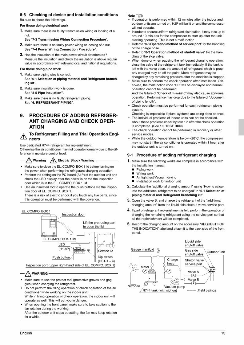
• Make sure to close the EL. COMPO. BOX 1 lid before turning on the power when performing the refrigerant charging operation.
• Perform the setting on the PC-board (A1P) of the outdoor unit and check the LED display after the power is on via the inspection door which is in the EL. COMPO. BOX 1 lid.
• Use an insulated rod to operate the push buttons via the inspec-tion door of EL. COMPO. BOX 1.There is a risk of electric shock if you touch any live parts, since this operation must be performed with the power on.
WARNING
• Make sure to use the protect tool (protective groves and gog-gles) when charging the refrigerant.
• Do not perform the filling operation or check operation of the air conditioner while working on the indoor unit.While in filling operation or check operation, the indoor unit will operate as well. This will put you in danger.
• When opening the front panel, make sure to take caution to the fan rotation during the working.After the outdoor unit stops operating, the fan may keep rotation for a while.
Note• If operation is performed within 12 minutes after the indoor and
outdoor units are turned on, H2P will be lit on and the compressor will not operate.
• In order to ensure uniform refrigerant distribution, it may take up to around 10 minutes for the compressor to start up after the unit starting operating. This is not a malfunction.
• Refer to “8-3 Operation method of service port” for the handling of the charge hose.
• Refer to “8-2 Operation method of shutoff valve” for the han-dling of the stop valve.
• When done or when pausing the refrigerant charging operation, close the valve of the refrigerant tank immediately. If the tank is left with the valve open, the amount of refrigerant which is prop-erly charged may be off the point. More refrigerant may be charged by any remaining pressure after the machine is stopped.
• Make sure to perform the check operation after installation. Oth-erwise, the malfunction code “U3” will be displayed and normal operation cannot be performed.And the failure of “Check of miswiring” may also cause abnormal operation. Performance may drop due to the failure of “Judgment of piping length”.
• Check operation must be performed for each refrigerant piping system.Checking is impossible if plural systems are being done at once.
• The individual problems of indoor units can not be checked.About these problems check by test run after the check operation is completed. (See 10. TEST RUN)
• The check operation cannot be performed in recovery or other service modes.
• While the outdoor temperature is below –20°C, the compressor may not start if the air conditioner is operated within 1 hour after the outdoor unit is turned on.
9-1 Procedure of adding refrigerant charging1. Make sure the following works are complete in accordance with
the installation manual.Piping workWiring workAir tight test/Vacuum dryingInstallation work for indoor unit
2. Calculate the “additional charging amount” using “How to calcu-late the additional refrigerant to be charged” in “6-1 Selection of piping material and Refrigerant branching kit”.
3. Open the valve B, and charge the refrigerant of the “additional charging amount” from the liquid side shutout valve service port.
4. If part of refrigerant replenishment is left, perform the operation of charging the remaining refrigerant using the service port so that all the replenishment will be completed.
5. Record the charging amount on the accessory “REQUEST FOR THE INDICATION” label and attach it to the back side of the front panel.
To Refrigerant Filling and Trial Operation Engi-neers
EL. COMPO. BOX 1Inspection door
EL. COMPO. BOX 1 lid
Lift the protruding part to open the lid
Dip switch(DS1-1 ~ 4)
Service lid
LED(H1-8P)
Push button
Inspection port (upper right-hand side of EL. COMPO. BOX 1)
Liquid side shutoff valve
Gas side shutoff valve
Vacuum pump
Valve A
Valve B
:Field pipings
Outdoor unit
Nitrogen
Meter
Gauge manifold
Charge hose
R744 tank (with siphon)
Shutoff valve service port
01_EN_3P233622-2E.fm Page 13 Tuesday, December 9, 2008 3:47 PM

14 English
<Operation procedure for charging additional refrigerant>Refer to the “Service Precautions” label on lid of the EL. COMPO. BOX 1 of the outdoor unit for operation settings for charging addi-tional refrigerant
(1) Fully open the shutoff valve on the gas side (with the shutoff valve on the liquid side and valve A shown in the above figure kept closed) to perform the operation of charging additional refrigerant.
(2) When the specified amount of refrigerant is filled, press the con-firmation button (BS3) on the PCB (A1P) of the outdoor unit to stop the operation of charging additional refrigerant.
(3) Fully open the liquid shutoff valve promptly, or otherwise a piping rupture may result from liquid seal.
[About the refrigerant tank]Check whether the tank has a siphon pipe before charging and place the tank so that the refrigerant is charged in liquid form. (See the fig-ure below.)
9-2 Check operationTake the following procedure to perform the check operation of the air conditioner.The following checks are made during the check operation. The air condi-tioner will not operate normally unless the check operation is performed.
Shutoff valve open checkWiring mistake checkPiping length check
Check Operation Procedure(1) Make on-site settings with the Dip switch (DS1-1) on the PCB
(A1P) of the outdoor unit as required.For details, refer to the information on on-site settings in the ser-vice precautions label on the EL. COMPO. BOX 1 lid.
(2) Close EL. COMPO. BOX 1 lid and all the front panels other than that on the EL. COMPO. BOX 1 side, and turn on the outdoor unit and all the indoor units in the same system. Be sure to turn the power on at least 6 hours before operation in order to have power running to the crank case heater.
(3) Make on-site settings with the push button switch (BS1-5) on the PCB (A1P) of the outdoor unit as required. For details, refer to the information on on-site settings in the “Service Precautions” label on the EL. COMPO. BOX 1 lid.
(4) Perform the check operation of the system according to the “Check Operation Procedure” in the “Service Precautions” label on the EL. COMPO. BOX 1 lid. After the system operates for approximately 30 to 40 minutes, the check operation of the sys-tem will automatically stop. Finish the check operation of the sys-tem if no malfunction code is displayed on the remote controller for each unit in the end. Then the air conditioner will be normally operable in approximately 5 minutes. If a malfunction code is dis-played, refer to the following list of [Remote controller displays malfunction code], remedy the problem, and perform the check operation of the system again.
[Remote controller displays malfunction code]
If any malfunction codes other than the above are displayed, check the service manual for how to respond.
10. TEST RUN• Make sure the following works are completed in accordance with
the installation manual.Piping workWiring workAir tight test / Vacuum dryingAdditional refrigerant chargeCheck operation
• Check that work on all the indoor units, BEV, and outdoor unit is finished and that it is safe to operate the system.
• After check operation is completed, operate the unit normally and check the following.(1) Make sure the indoor and outdoor units are operating nor-
mally.(2) Operate each indoor unit one by one and make sure the cor-
responding outdoor unit is also operating.(3) Check to see if cold (or hot) air is coming out from the indoor
unit.(4) Push the fan direction and strength buttons on the remote
controller to see if they operate properly.
Note• Heating is not possible if the outdoor temperature is 24°C or
higher. Refer to the Operation manual.• If a knocking sound can be heard in the liquid compression of the
compressor, stop the unit immediately and then energize the crank case heater for a sufficient length of time before restarting the operation.
• Once stopping, the compressor will not restart in about 5 minutes even if the On/Off button of the remote controller is pushed.
• When the system operation is stopped by the remote controller, the outdoor units may continue operating for further 5 minutes at maximum.
• The outdoor unit fan may rotate at low speeds if the Night-time low noise setting or the External low noise level setting is made, but this is not a malfunction.
With siphon pipe
Other tanks
EL. COMPO. BOX 1 (Right side)
“Service Precautions” label(Surface of EL. COMPO. BOX 1 lid (right-hand side) )
Stand the tank upright and charge.(The siphon pipe goes all the way inside, so the tank does not need be put upside-down charge in liquid form.)
Stand the tank upside-down and charge.
Malfunc-tion code
Installation error Remedial action
E3, E4F3, F6UF
The shutoff valve of the outdoor unit is left closed.
Open the shutoff valve.
U1The phases of the power to the outdoor unit is reversed.
Exchange two of the three phases to make a proper connection.
U1U4LC
No power is supplied to an outdoor or indoor unit (including phase interruption).
Make sure the power source wire is properly connected to the outdoor unit and revise if necessary.
UF
There is conflict on the connection of trans-mission wiring in the system.
Check if the refrigerant piping line and the transmission wir-ing are consistent with each other.
E3F6UF
Refrigerant over-charge.
Recalculate the additional amount refrigerant from the piping length and correct the refrigerant charge level.
E4F3
Insufficient refrigerant.
• Check if the additional refrig-erant charge has been fin-ished correctly.
• Recalculate the additional amount refrigerant from the piping length and add the adequate amount.
U7, U4UF, UH
If the outdoor unit ter-minal is connected when there is one out-door unit installed.
Remove the line from the outdoor multi terminals (Q1 and Q2).
01_EN_3P233622-2E.fm Page 14 Tuesday, December 9, 2008 3:47 PM

English 15
• If the check operation of the system is not performed with the test run button pressed when the air conditioner is installed, the mal-function code “U3” will be displayed. Refer to “9-2 Check opera-tion” and perform the check operation of the system.
At the time of delivering the product to the customer after the test run is completed, check that the EL. COMPO. BOX 1 lid, service lid (inspection port lid), and the casings of the air conditioner are mounted.
To Test Run Engineer
01_EN_3P233622-2E.fm Page 15 Tuesday, December 9, 2008 3:47 PM

3P233622-2E EM08A074B (0812) HT
00_CV_3P233622-2E.fm Page 2 Thursday, November 27, 2008 1:56 PM


![PC1616/PC1832/PC1864 STANDARD INSTALLATION GUIDE v4[1] (1).1 Installation Manual.pdf · PC1616/PC1832/PC1864 STANDARD INSTALLATION GUIDE This Installation Guide provides the basic](https://img.pdfslide.net/doc/110x75/5e09912e8476ee27bc7a0dba/pc1616pc1832pc1864-standard-installation-v41-11-installation-manualpdf.jpg)


![Installation Presentation[1]](https://img.pdfslide.net/doc/110x75/577ce7901a28abf103957261/installation-presentation1.jpg)
![Cb Installation[1]](https://img.pdfslide.net/doc/110x75/577d23931a28ab4e1e9a2e43/cb-installation1.jpg)