Embed Size (px)
Citation preview
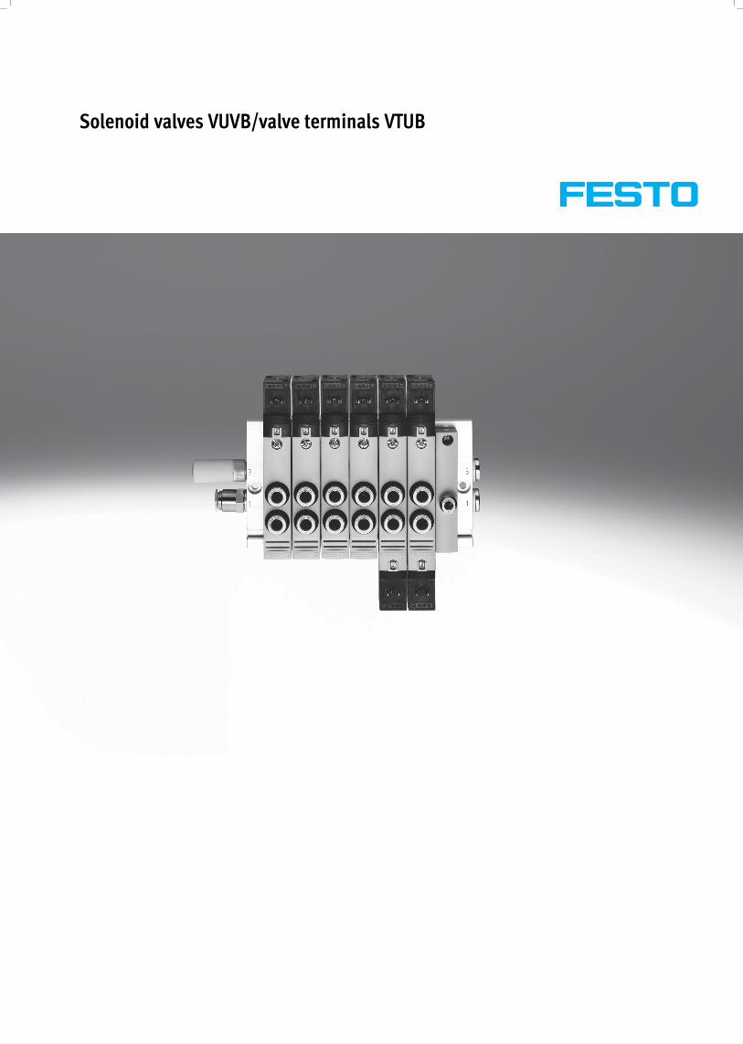
Solenoid valves VUVB/valve terminals VTUB
Subject to change – 2014/022 � Internet: www.festo.com/catalogue/...
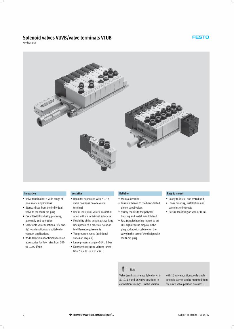
Solenoid valves VUVB/valve terminals VTUBKey features
Innovative Versatile Reliable Easy to mount
• Valve terminal for a wide range of
pneumatic applications
• Standardised from the individual
valve to the multi-pin plug
• Great flexibility during planning,
assembly and operation
• Selectable valve functions; 3/2 and
4/2-way function also suitable for
vacuum applications
• Wide selection of optimally tailored
accessories for flow rates from 200
to 1,000 l/min
• Room for expansion with 2 … 16
valve positions on one valve
terminal
• Use of individual valves in combin-
ation with an individual sub-base
• Flexibility of the pneumatic working
lines provides a practical solution
to different requirements
• Two pressure zones (additional
zones on request)
• Large pressure range –0.9 … 8 bar
• Extensive operating voltage range
from 12 V DC to 230 V AC
• Manual override
• Durable thanks to tried-and-tested
piston spool valves
• Sturdy thanks to the polymer
housing and metal manifold rail
• Fast troubleshooting thanks to an
LED signal status display in the
plug socket with cable or on the
valve in the case of the design with
multi-pin plug
• Ready-to-install and tested unit
• Lower ordering, installation and
commissioning costs
• Secure mounting on wall or H-rail
-H- Note
Valve terminals are available for 4, 6,
8, 10, 12 and 16 valve positions in
connection size G½. On the version
with 16 valve positions, only single
solenoid valves can be mounted from
the ninth valve position onwards.
2014/02 – Subject to change 3� Internet: www.festo.com/catalogue/...
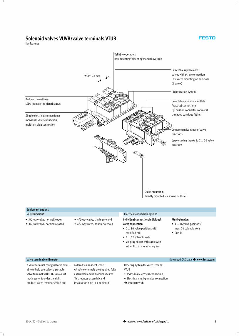
Solenoid valves VUVB/valve terminals VTUBKey features
Reduced downtimes:
LEDs indicate the signal status
Reliable operation:
non-detenting/detenting manual override
Width 20 mm
Simple electrical connections:
individual valve connection,
multi-pin plug connection
Quick mounting:
directly mounted via screws or H-rail
Easy valve replacement:
valves with screw connection
Fast valve mounting on sub-base
(1 screw)
Space-saving thanks to 2 … 16 valve
positions
Selectable pneumatic outlets
Practical connection:
QS push-in connectors or metal
threaded cartridge fitting
Comprehensive range of valve
functions
Identification system
Equipment options
Valve functions Electrical connection options
• 3/2-way valve, normally open
• 3/2-way valve, normally closed
• 4/2-way valve, single solenoid
• 4/2-way valve, double solenoid
Individual connection/individual
valve connection
• 2 … 16 valve positions with
manifold rail
• 2 … 32 solenoid coils
• Via plug socket with cable with
either LED or illuminating seal
Multi-pin plug
• 4 … 16 valve positions/
max. 24 solenoid coils
• Sub-D
Valve terminal configurator Download CAD data� www.festo.com
A valve terminal configurator is avail-
able to help you select a suitable
valve terminal VTUB. This makes it
much easier to order the right
product. Valve terminals VTUB are
ordered via an ident. code.
All valve terminals are supplied fully
assembled and individually tested.
This reduces assembly and
installation time to a minimum.
Ordering system for valve terminal
VTUB
• Individual electrical connection
• Electrical multi-pin plug connection
� Internet: vtub
Subject to change – 2014/024 � Internet: www.festo.com/catalogue/...
Solenoid valves VUVB/valve terminals VTUBKey features
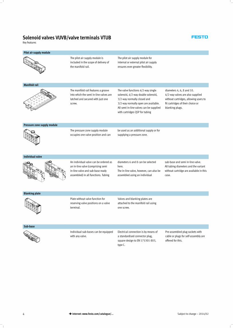
Pilot air supply module
The pilot air supply module is
included in the scope of delivery of
the manifold rail.
The pilot air supply module for
internal or external pilot air supply
ensures even greater flexibility.
Manifold rail
The manifold rail features a groove
into which the semi in-line valves are
latched and secured with just one
screw.
The valve functions 4/2-way single
solenoid, 4/2-way double solenoid,
3/2-way normally closed and
3/2-way normally open are available.
All semi in-line valves can be supplied
with cartridges QSP for tubing
diameters 4, 6, 8 and 10.
4/2-way valves are also supplied
without cartridges, allowing users to
fit cartridges of their choice or
blanking plugs.
Pressure zone supply module
The pressure zone supply module
occupies one valve position and can
be used as an additional supply or for
supplying a pressure zone.
Individual valve
An individual valve can be ordered as
an in-line valve (comprising semi
in-line valve and sub-base ready
assembled) in all functions. Tubing
diameters 6 and 8 can be selected
here.
The in-line valve, however, can also be
assembled using an individual
sub-base and semi in-line valve.
All tubing diameters and the variant
without cartridge are available in this
case.
Blanking plate
Plate without valve function for
reserving valve positions on a valve
terminal.
Valves and blanking plates are
attached to the manifold rail using
one screw.
Sub-base
Individual sub-bases can be equipped
with any valve.
Electrical connection is by means of
a standardised connector plug,
square design to EN 175301-803,
type C.
Pre-assembled plug sockets with
cable or plugs for self-assembly are
offered for this.
2014/02 – Subject to change 5� Internet: www.festo.com/catalogue/...
Solenoid valves VUVB/valve terminals VTUBKey features – Pneumatic components
Pneumatic connection
Supply and exhaust
The valves are supplied pneumatically
via manifold rails or individual
sub-bases.
The manifold rails contain common
lines for compressed air supply, ex-
haust and pilot exhaust for all valves.
The common lines can be connected
• at the left (code L),
• at the right (code R) or
• at both ends (no code).
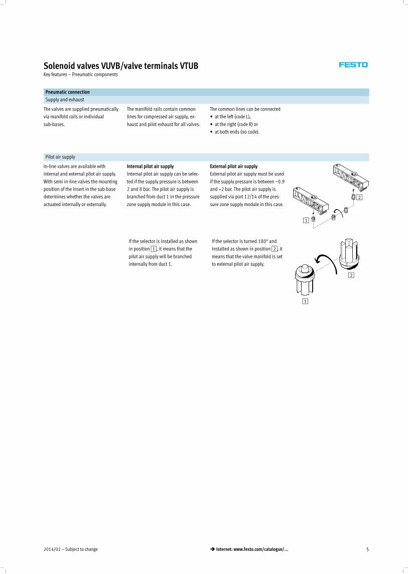
Pilot air supply
In-line valves are available with
internal and external pilot air supply.
With semi in-line valves the mounting
position of the insert in the sub-base
determines whether the valves are
actuated internally or externally.
Internal pilot air supply
Internal pilot air supply can be selec-
ted if the supply pressure is between
2 and 8 bar. The pilot air supply is
branched from duct 1 in the pressure
zone supply module in this case.
External pilot air supply
External pilot air supply must be used
if the supply pressure is between –0.9
and +2 bar. The pilot air supply is
supplied via port 12/14 of the pres-
sure zone supply module in this case.
1
2
If the selector is installed as shown
in position1, it means that the
pilot air supply will be branched
internally from duct 1.
If the selector is turned 180° and
installed as shown in position2, it
means that the valve manifold is set
to external pilot air supply.
2
1
Subject to change – 2014/026 � Internet: www.festo.com/catalogue/...
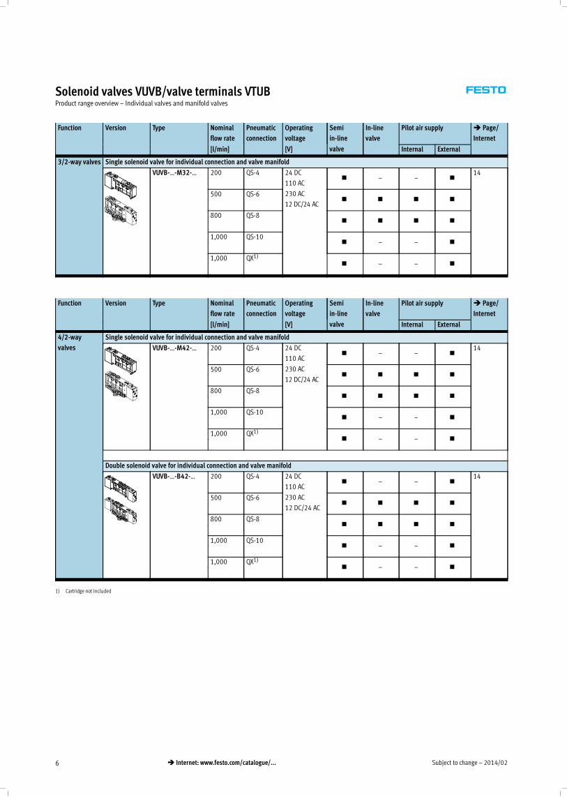
Solenoid valves VUVB/valve terminals VTUBProduct range overview – Individual valves and manifold valves
Function Version Type Nominal
flow rate
Pneumatic
connection
Operating
voltage
Semi
in-line
valve
In-line
valve
Pilot air supply � Page/
Internet
[l/min] [V] Internal External
3/2-way valves Single solenoid valve for individual connection and valve manifold
VUVB-…-M32-… 200 QS-4 24 DC
110 AC
230 AC
12 DC/24 AC
� – – �14
500 QS-6� � � �
800 QS-8� � � �
1,000 QS-10� – – �
1,000 QX1)� – – �
Function Version Type Nominal
flow rate
Pneumatic
connection
Operating
voltage
Semi
in-line
valve
In-line
valve
Pilot air supply � Page/
Internet
[l/min] [V] Internal External
4/2-way
valves
Single solenoid valve for individual connection and valve manifold
VUVB-…-M42-… 200 QS-4 24 DC
110 AC
230 AC
12 DC/24 AC
� – – �14
500 QS-6� � � �
800 QS-8� � � �
1,000 QS-10� – – �
1,000 QX1)� – – �
Double solenoid valve for individual connection and valve manifold
VUVB-…-B42-… 200 QS-4 24 DC
110 AC
230 AC
12 DC/24 AC
� – – �14
500 QS-6� � � �
800 QS-8� � � �
1,000 QS-10� – – �
1,000 QX1)� – – �
1) Cartridge not included
2014/02 – Subject to change 7� Internet: www.festo.com/catalogue/...
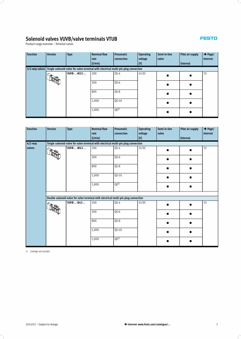
Solenoid valves VUVB/valve terminals VTUBProduct range overview – Terminal valves
Function Version Type Nominal flow
rate
Pneumatic
connection
Operating
voltage
Semi in-line
valve
Pilot air supply � Page/
Internet
[l/min] [V] External
3/2-way valves Single solenoid valve for valve terminal with electrical multi-pin plug connection
VUVB-…-M32-… 200 QS-4 24 DC� �
35
500 QS-6� �
800 QS-8� �
1,000 QS-10� �
1,000 QX1)� �
Function Version Type Nominal flow
rate
Pneumatic
connection
Operating
voltage
Semi in-line
valve
Pilot air supply � Page/
Internet
[l/min] [V] External
4/2-way
valves
Single solenoid valve for valve terminal with electrical multi-pin plug connection
VUVB-…-M42-… 200 QS-4 24 DC� �
35
500 QS-6� �
800 QS-8� �
1,000 QS-10� �
1,000 QX1)� �
Double solenoid valve for valve terminal with electrical multi-pin plug connection
VUVB-…-B42-… 200 QS-4 24 DC� �
35
500 QS-6� �
800 QS-8� �
1,000 QS-10� �
1,000 QX1)� �
1) Cartridge not included
Subject to change – 2014/028 � Internet: www.festo.com/catalogue/...
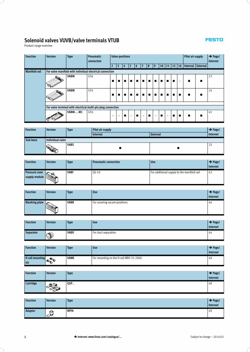
Solenoid valves VUVB/valve terminals VTUBProduct range overview
Function Version Type Pneumatic
connection
Valve positions Pilot air supply � Page/
Internet
2 3 4 5 6 7 8 9 10 11 12 16 Internal External
Manifold rail For valve manifold with individual electrical connection
VABM G¼
� � � � � � � � � � � – � �
23
VABM G½
� � � � � � � � � � � � � �
24
For valve terminal with electrical multi-pin plug connection
VABM-…-M1 G½– – � – � – � – � – � � � �
41
Function Version Type Pilot air supply � Page/
InternetInternal External
Sub-base Individual valve
VABS� �
25
Function Version Type Pneumatic connection Use � Page/
Internet
Pressure zone
supply module
VABF QS-10 For additional supply to the manifold rail 43
Function Version Type Use � Page/
Internet
Blanking plate VABB For covering vacant positions 44
Function Version Type Use � Page/
Internet
Separator VABD For duct separation 44
Function Version Type Use � Page/
Internet
H-rail mounting
kit
VAME For mounting on the H-rail NRH-35-2000 49
Function Version Type � Page/
Internet
Cartridge QSP… 48
Function Version Type � Page/
Internet
Adapter NPFA 49
2014/02 – Subject to change 9� Internet: www.festo.com/catalogue/...
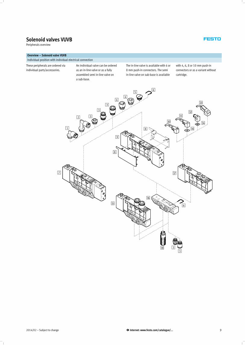
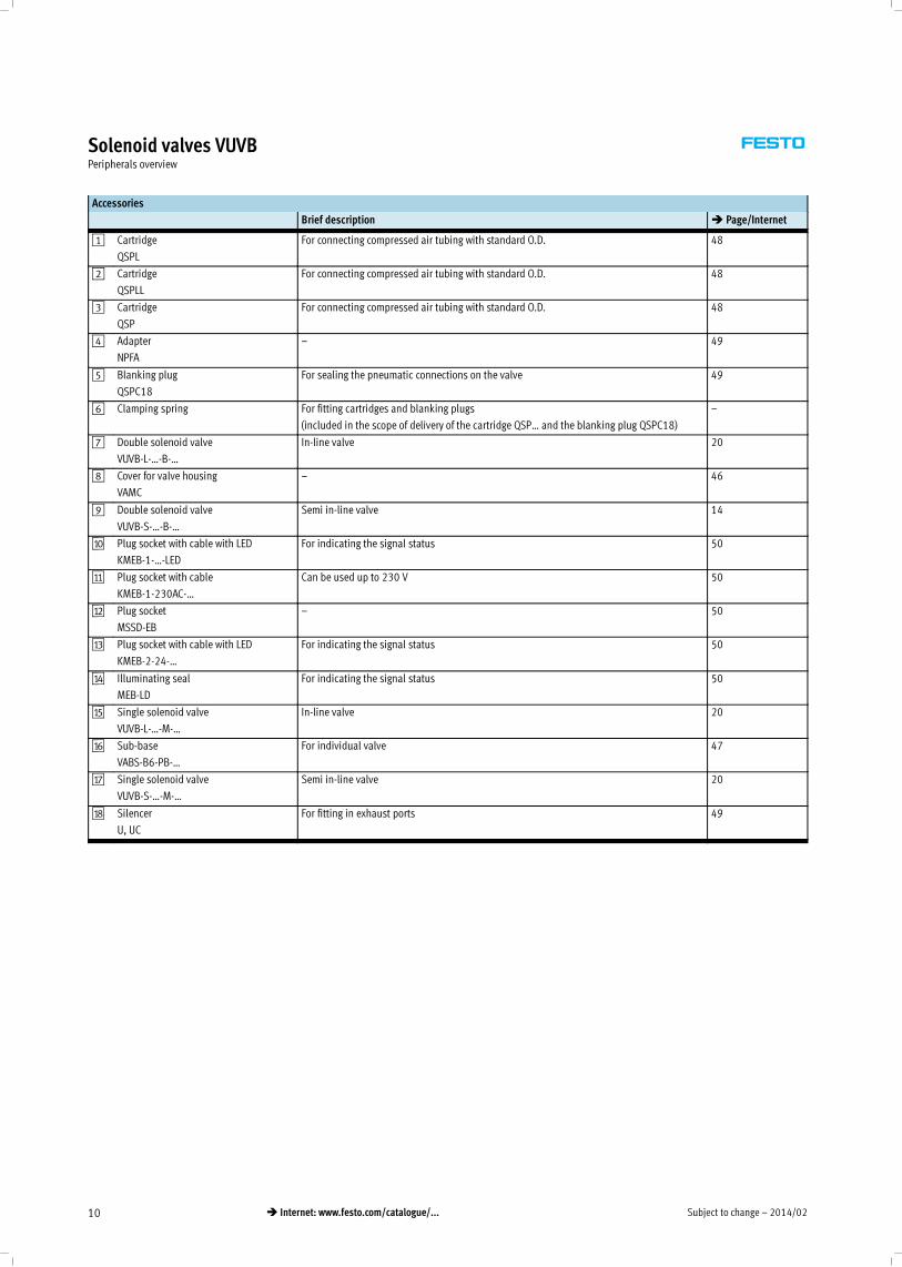
Solenoid valves VUVBPeripherals overview
Overview – Solenoid valve VUVB
Individual position with individual electrical connection
These peripherals are ordered via
individual parts/accessories.
An individual valve can be ordered
as an in-line valve or as a fully
assembled semi in-line valve on
a sub-base.
The in-line valve is available with 6 or
8 mm push-in connectors. The semi
in-line valve on sub-base is available
with 4, 6, 8 or 10 mm push-in
connectors or as a variant without
cartridge.
1
2 3
4
56
7
8
8
9
aJ
aA
aE
aC
aB
aD
3
3
4
aF
aG
aH 33
aD
6
Subject to change – 2014/0210 � Internet: www.festo.com/catalogue/...
Solenoid valves VUVBPeripherals overview
Accessories
Brief description � Page/Internet
1 Cartridge
QSPL
For connecting compressed air tubing with standard O.D. 48
2 Cartridge
QSPLL
For connecting compressed air tubing with standard O.D. 48
3 Cartridge
QSP
For connecting compressed air tubing with standard O.D. 48
4 Adapter
NPFA
– 49
5 Blanking plug
QSPC18
For sealing the pneumatic connections on the valve 49
6 Clamping spring For fitting cartridges and blanking plugs
(included in the scope of delivery of the cartridge QSP… and the blanking plug QSPC18)
–
7 Double solenoid valve
VUVB-L-…-B-…
In-line valve 20
8 Cover for valve housing
VAMC
– 46
9 Double solenoid valve
VUVB-S-…-B-…
Semi in-line valve 14
aJ Plug socket with cable with LED
KMEB-1-…-LED
For indicating the signal status 50
aA Plug socket with cable
KMEB-1-230AC-…
Can be used up to 230 V 50
aB Plug socket
MSSD-EB
– 50
aC Plug socket with cable with LED
KMEB-2-24-…
For indicating the signal status 50
aD Illuminating seal
MEB-LD
For indicating the signal status 50
aE Single solenoid valve
VUVB-L-…-M-…
In-line valve 20
aF Sub-base
VABS-B6-PB-…
For individual valve 47
aG Single solenoid valve
VUVB-S-…-M-…
Semi in-line valve 20
aH Silencer
U, UC
For fitting in exhaust ports 49
2014/02 – Subject to change 11� Internet: www.festo.com/catalogue/...
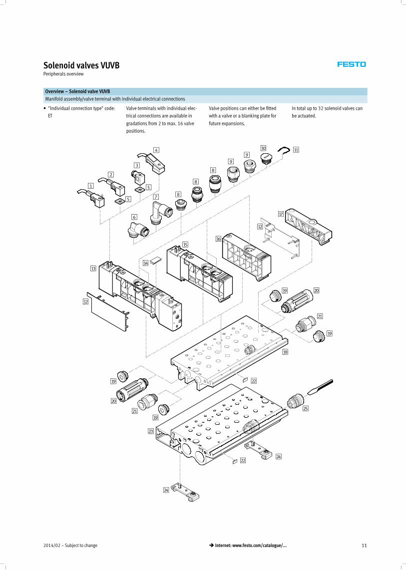
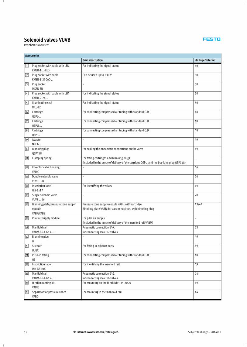
Solenoid valves VUVBPeripherals overview
Overview – Solenoid valve VUVB
Manifold assembly/valve terminal with individual electrical connections
• "Individual connection type" code:
ET
Valve terminals with individual elec-
trical connections are available in
gradations from 2 to max. 16 valve
positions.
Valve positions can either be fitted
with a valve or a blanking plate for
future expansions.
In total up to 32 solenoid valves can
be actuated.
1
2
3
4
5
5
6
7 8
8
8
99
aJ aA
aB
aCaD
aE
aB
aF
aG
aH
aI
aI
bJ
bJ
bA
bA
bB
bB
bC
bD
bD
bE
aI
aI
Subject to change – 2014/0212 � Internet: www.festo.com/catalogue/...
Solenoid valves VUVBPeripherals overview
Accessories
Brief description � Page/Internet
1 Plug socket with cable with LED
KMEB-1-…-LED
For indicating the signal status 50
2 Plug socket with cable
KMEB-1-230AC-…
Can be used up to 230 V 50
3 Plug socket
MSSD-EB
– 50
4 Plug socket with cable with LED
KMEB-2-24-…
For indicating the signal status 50
5 Illuminating seal
MEB-LD
For indicating the signal status 50
6 Cartridge
QSPL-…
For connecting compressed air tubing with standard O.D. 48
7 Cartridge
QSPLL-…
For connecting compressed air tubing with standard O.D. 48
8 Cartridge
QSP-…
For connecting compressed air tubing with standard O.D. 48
9 Adapter
NPFA-…
– 49
aJ Blanking plug
QSPC18
For sealing the pneumatic connections on the valve 49
aA Clamping spring For fitting cartridges and blanking plugs
(included in the scope of delivery of the cartridge QSP… and the blanking plug QSPC18)
–
aB Cover for valve housing
VAMC
– 46
aC Double solenoid valve
VUVB-…-B
– 20
aD Inscription label
IBS-9x17
For identifying the valves 49
aE Single solenoid valve
VUVB-…-M
– 20
aF Blanking plate/pressure zone supply
module
VABF/VABB
Pressure zone supply module VABF: with cartridge
Blanking plate VABB: for vacant position, with blanking plug
43/44
aG Pilot air supply module For pilot air supply
(included in the scope of delivery of the manifold rail VABM)
–
aH Manifold rail
VABM-B6-E-G14-…
Pneumatic connection G¼,
for connecting max. 12 valves
23
aI Blanking plug
B
– 49
bJ Silencer
U, UC
For fitting in exhaust ports 49
bA Push-in fitting
QS
For connecting compressed air tubing with standard O.D. 48
bB Inscription label
MH-BZ-80X
For identifying the manifold rail 49
bC Manifold rail
VABM-B6-E-G12-…
Pneumatic connection G½,
for connecting max. 16 valves
24
bD H-rail mounting kit
VAME
For mounting on the H-rail NRH-35-2000 49
bE Separator for pressure zones
VABD
For mounting in the manifold rail 44
2014/02 – Subject to change 13� Internet: www.festo.com/catalogue/...
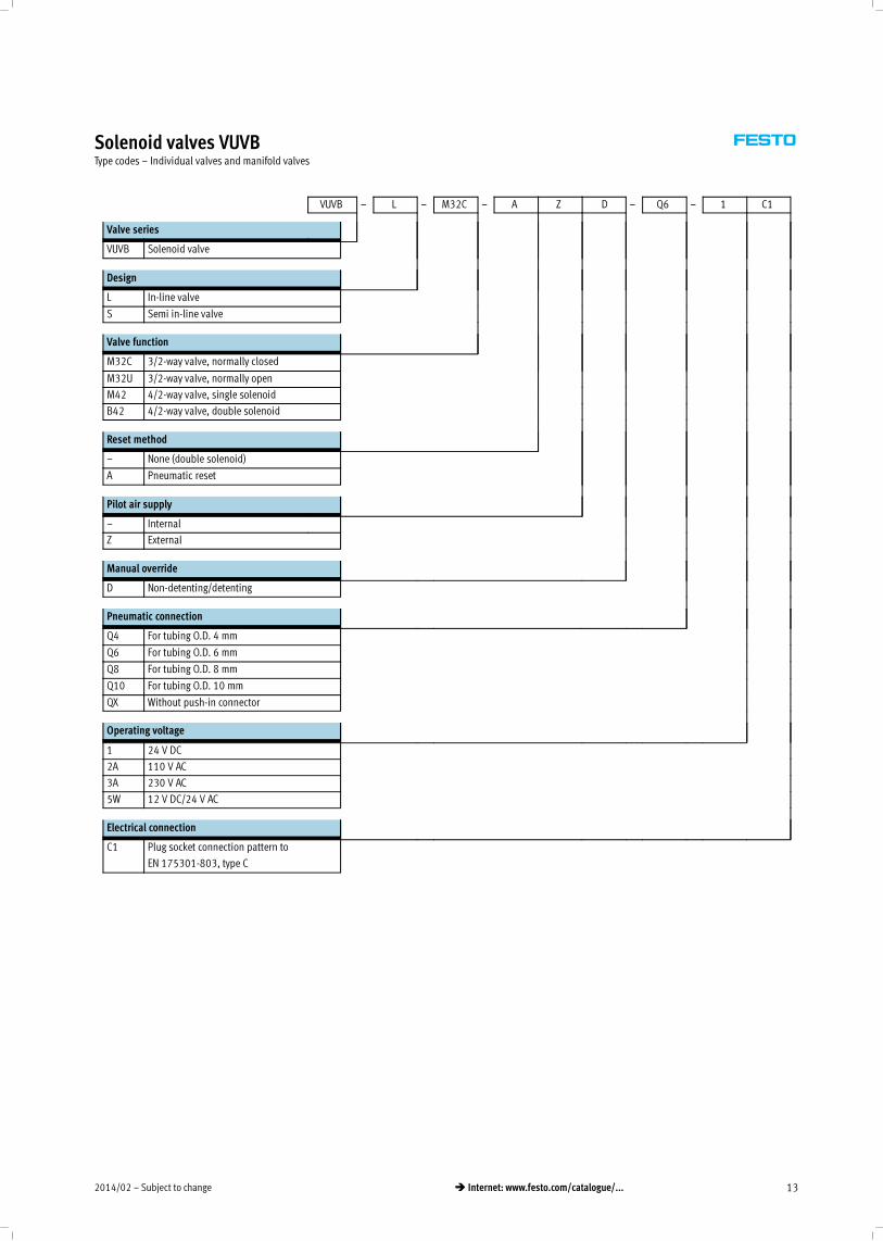
Solenoid valves VUVBType codes – Individual valves and manifold valves
VUVB – L – M32C – A Z D – Q6 – 1 C1
Valve series
VUVB Solenoid valve
Design
L In-line valve
S Semi in-line valve
Valve function
M32C 3/2-way valve, normally closed
M32U 3/2-way valve, normally open
M42 4/2-way valve, single solenoid
B42 4/2-way valve, double solenoid
Reset method
– None (double solenoid)
A Pneumatic reset
Pilot air supply
– Internal
Z External
Manual override
D Non-detenting/detenting
Pneumatic connection
Q4 For tubing O.D. 4 mm
Q6 For tubing O.D. 6 mm
Q8 For tubing O.D. 8 mm
Q10 For tubing O.D. 10 mm
QX Without push-in connector
Operating voltage
1 24 V DC
2A 110 V AC
3A 230 V AC
5W 12 V DC/24 V AC
Electrical connection
C1 Plug socket connection pattern to
EN 175301-803, type C
Subject to change – 2014/0214 � Internet: www.festo.com/catalogue/...
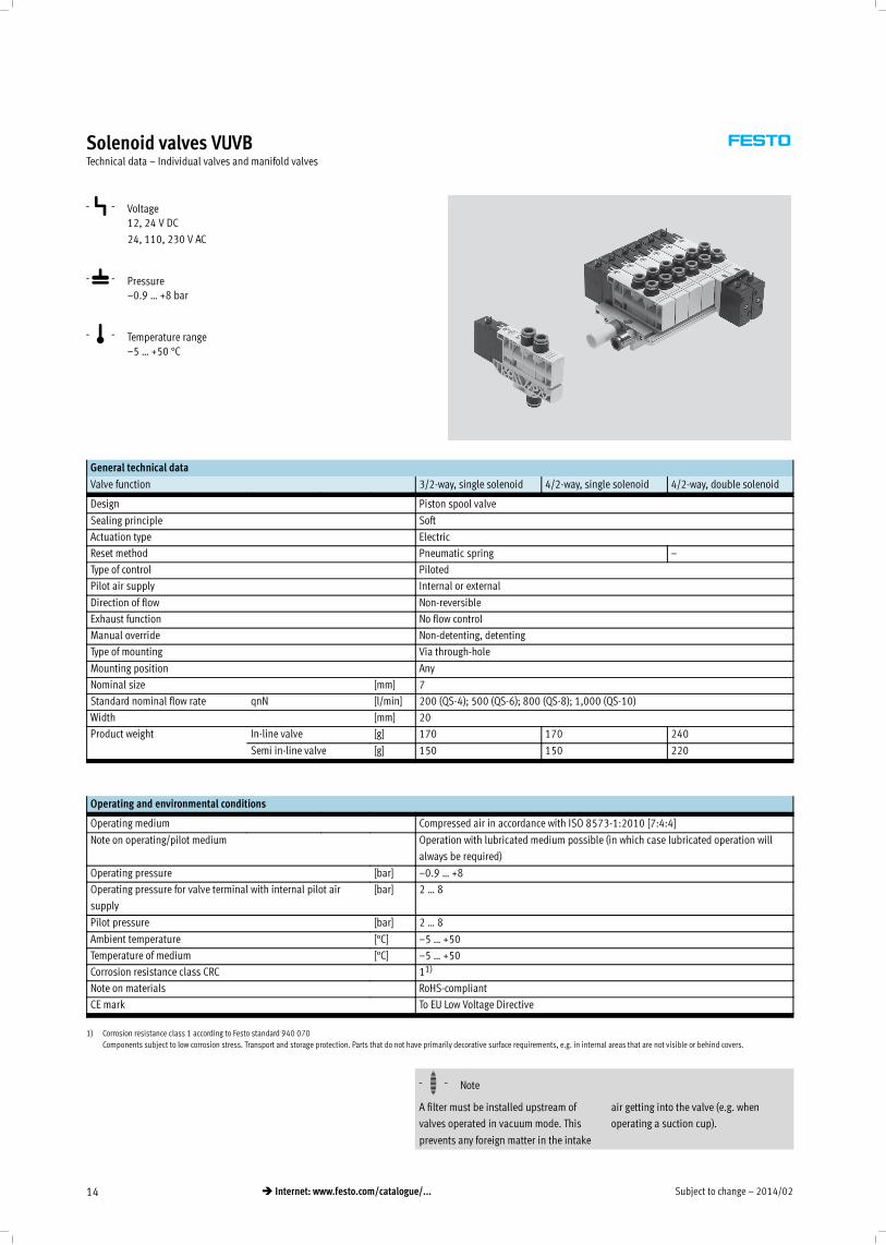
Solenoid valves VUVBTechnical data – Individual valves and manifold valves
-P- Voltage
12, 24 V DC
24, 110, 230 V AC
-L- Pressure
–0.9 … +8 bar
-Q- Temperature range
–5 … +50 °C
General technical data
Valve function 3/2-way, single solenoid 4/2-way, single solenoid 4/2-way, double solenoid
Design Piston spool valve
Sealing principle Soft
Actuation type Electric
Reset method Pneumatic spring –
Type of control Piloted
Pilot air supply Internal or external
Direction of flow Non-reversible
Exhaust function No flow control
Manual override Non-detenting, detenting
Type of mounting Via through-hole
Mounting position Any
Nominal size [mm] 7
Standard nominal flow rate qnN [l/min] 200 (QS-4); 500 (QS-6); 800 (QS-8); 1,000 (QS-10)
Width [mm] 20
Product weight In-line valve [g] 170 170 240
Semi in-line valve [g] 150 150 220
Operating and environmental conditions
Operating medium Compressed air in accordance with ISO 8573-1:2010 [7:4:4]
Note on operating/pilot medium Operation with lubricated medium possible (in which case lubricated operation will
always be required)
Operating pressure [bar] –0.9 … +8
Operating pressure for valve terminal with internal pilot air
supply
[bar] 2 … 8
Pilot pressure [bar] 2 … 8
Ambient temperature [°C] –5 … +50
Temperature of medium [°C] –5 … +50
Corrosion resistance class CRC 11)
Note on materials RoHS-compliant
CE mark To EU Low Voltage Directive*
1) Corrosion resistance class 1 according to Festo standard 940 070
Components subject to low corrosion stress. Transport and storage protection. Parts that do not have primarily decorative surface requirements, e.g. in internal areas that are not visible or behind covers.
-H- Note
A filter must be installed upstream of
valves operated in vacuum mode. This
prevents any foreign matter in the intake
air getting into the valve (e.g. when
operating a suction cup).
2014/02 – Subject to change 15� Internet: www.festo.com/catalogue/...
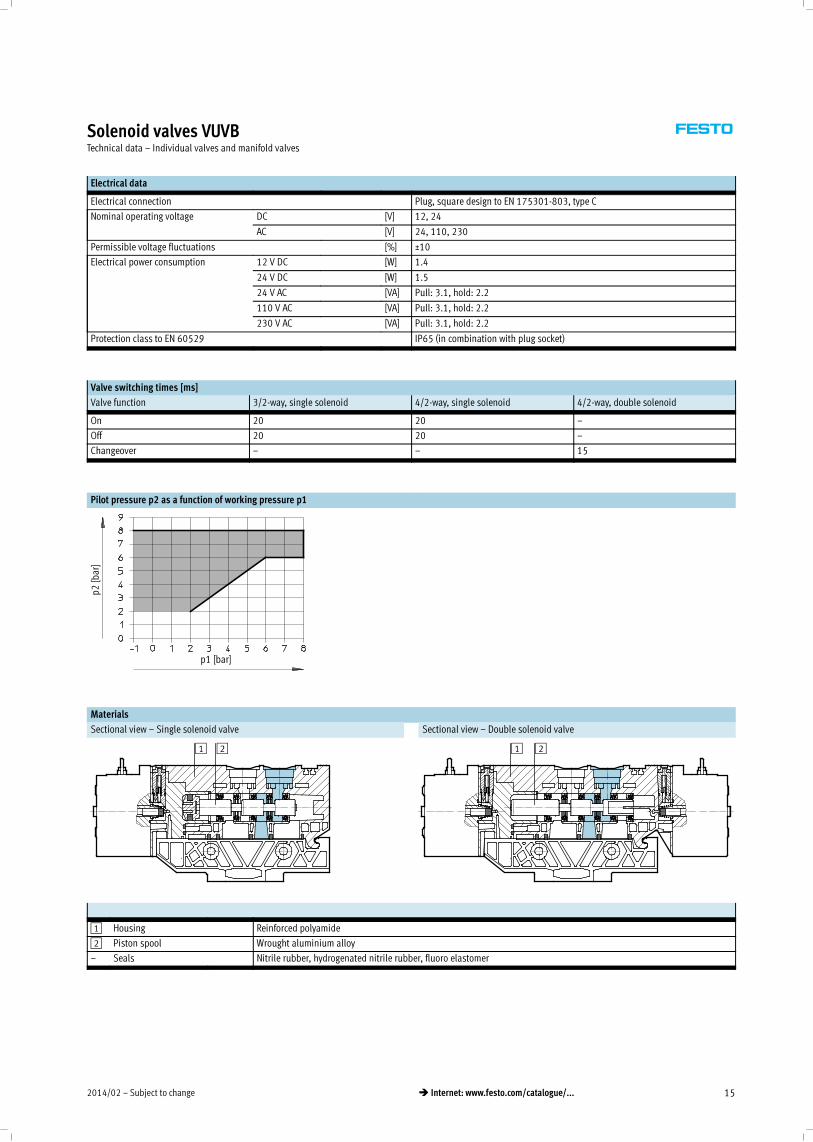
Solenoid valves VUVBTechnical data – Individual valves and manifold valves
Electrical data
Electrical connection Plug, square design to EN 175301-803, type C
Nominal operating voltage DC [V] 12, 24
AC [V] 24, 110, 230
Permissible voltage fluctuations [%] ±10
Electrical power consumption 12 V DC [W] 1.4
24 V DC [W] 1.5
24 V AC [VA] Pull: 3.1, hold: 2.2
110 V AC [VA] Pull: 3.1, hold: 2.2
230 V AC [VA] Pull: 3.1, hold: 2.2
Protection class to EN 60529 IP65 (in combination with plug socket)
Valve switching times [ms]
Valve function 3/2-way, single solenoid 4/2-way, single solenoid 4/2-way, double solenoid
On 20 20 –
Off 20 20 –
Changeover – – 15
Pilot pressure p2 as a function of working pressure p1
p2[bar]
p1 [bar]
Materials
Sectional view – Single solenoid valve Sectional view – Double solenoid valve
1 2 1 2
1 Housing Reinforced polyamide
2 Piston spool Wrought aluminium alloy
– Seals Nitrile rubber, hydrogenated nitrile rubber, fluoro elastomer
Subject to change – 2014/0216 � Internet: www.festo.com/catalogue/...
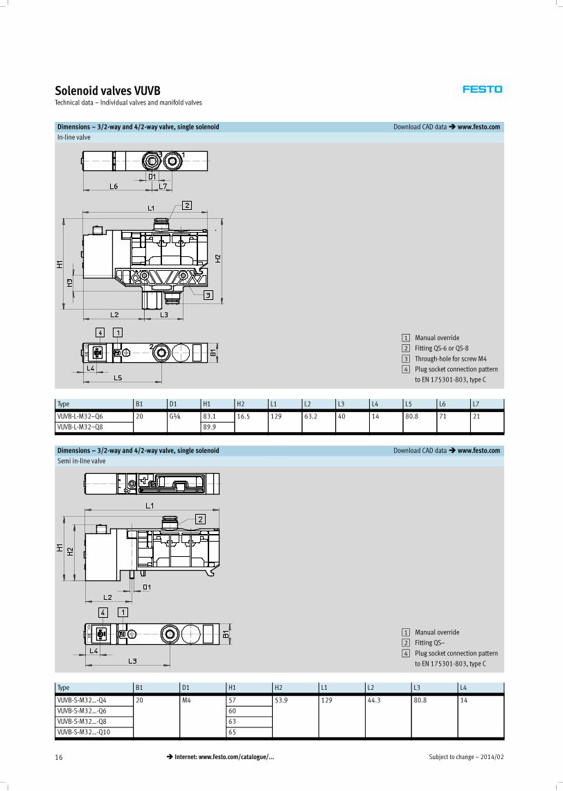
Solenoid valves VUVBTechnical data – Individual valves and manifold valves
Dimensions – 3/2-way and 4/2-way valve, single solenoid Download CAD data� www.festo.com
In-line valve
1 Manual override
2 Fitting QS-6 or QS-8
3 Through-hole for screw M4
4 Plug socket connection pattern
to EN 175301-803, type C
Type B1 D1 H1 H2 L1 L2 L3 L4 L5 L6 L7
VUVB-L-M32–Q6 20 G¼ 83.1 16.5 129 63.2 40 14 80.8 71 21
VUVB-L-M32–Q8 89.9
Dimensions – 3/2-way and 4/2-way valve, single solenoid Download CAD data� www.festo.com
Semi in-line valve
1 Manual override
2 Fitting QS–
4 Plug socket connection pattern
to EN 175301-803, type C
Type B1 D1 H1 H2 L1 L2 L3 L4
VUVB-S-M32…-Q4 20 M4 57 53.9 129 44.3 80.8 14
VUVB-S-M32…-Q6 60
VUVB-S-M32…-Q8 63
VUVB-S-M32…-Q10 65
2014/02 – Subject to change 17� Internet: www.festo.com/catalogue/...
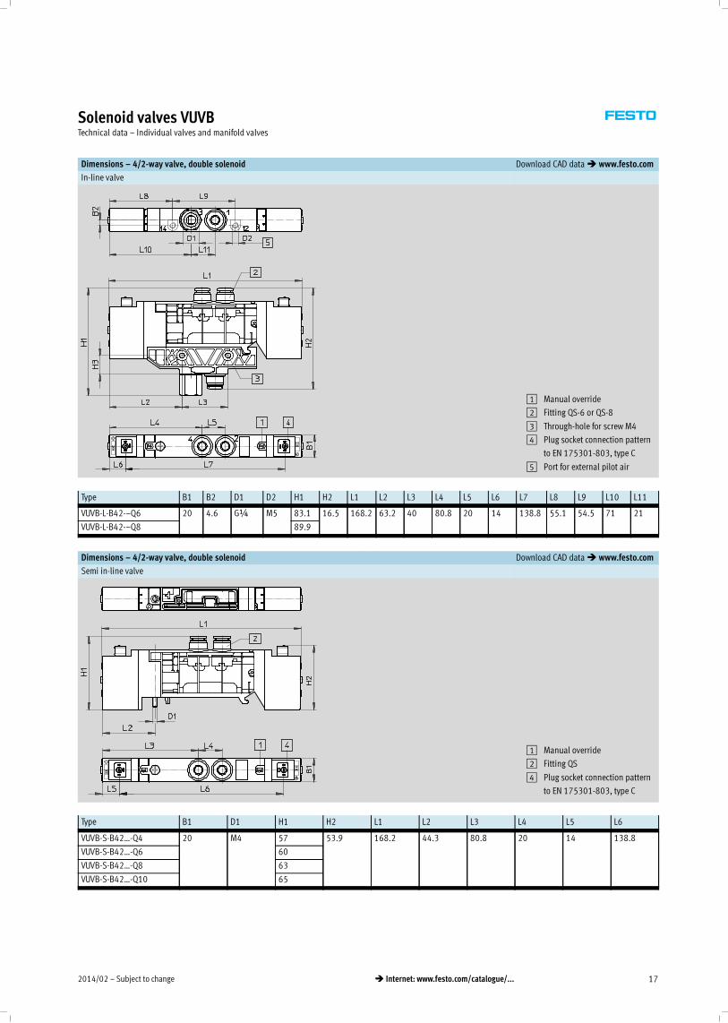
Solenoid valves VUVBTechnical data – Individual valves and manifold valves
Dimensions – 4/2-way valve, double solenoid Download CAD data� www.festo.com
In-line valve
1 Manual override
2 Fitting QS-6 or QS-8
3 Through-hole for screw M4
4 Plug socket connection pattern
to EN 175301-803, type C
5 Port for external pilot air
Type B1 B2 D1 D2 H1 H2 L1 L2 L3 L4 L5 L6 L7 L8 L9 L10 L11
VUVB-L-B42-–Q6 20 4.6 G¼ M5 83.1 16.5 168.2 63.2 40 80.8 20 14 138.8 55.1 54.5 71 21
VUVB-L-B42-–Q8 89.9
Dimensions – 4/2-way valve, double solenoid Download CAD data� www.festo.com
Semi in-line valve
1 Manual override
2 Fitting QS
4 Plug socket connection pattern
to EN 175301-803, type C
Type B1 D1 H1 H2 L1 L2 L3 L4 L5 L6
VUVB-S-B42…-Q4 20 M4 57 53.9 168.2 44.3 80.8 20 14 138.8
VUVB-S-B42…-Q6 60
VUVB-S-B42…-Q8 63
VUVB-S-B42…-Q10 65
Subject to change – 2014/0218 � Internet: www.festo.com/catalogue/...
Solenoid valves VUVBTechnical data – Individual valves and manifold valves
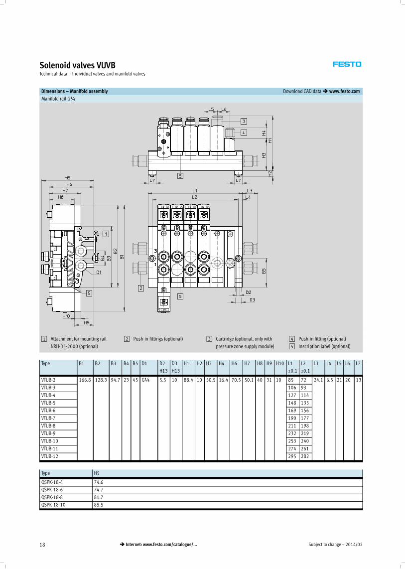
Dimensions – Manifold assembly Download CAD data� www.festo.com
Manifold rail G¼
1 Attachment for mounting rail
NRH-35-2000 (optional)
2 Push-in fittings (optional) 3 Cartridge (optional, only with
pressure zone supply module)
4 Push-in fitting (optional)
5 Inscription label (optional)
Type B1 B2 B3 B4 B5 D1 D2 D3 H1 H2 H3 H4 H6 H7 H8 H9 H10 L1 L2 L3 L4 L5 L6 L7
H13 H13 _0.1 _0.1
VTUB-2 166.8 128.3 94.7 23 45 G¼ 5.5 10 88.4 10 50.5 16.4 70.5 50.1 40 31 10 85 72 24.1 6.5 21 20 13
VTUB-3 106 93
VTUB-4 127 114
VTUB-5 148 135
VTUB-6 169 156
VTUB-7 190 177
VTUB-8 211 198
VTUB-9 232 219
VTUB-10 253 240
VTUB-11 274 261
VTUB-12 295 282
Type H5
QSPK-18-4 74.6
QSPK-18-6 74.7
QSPK-18-8 81.7
QSPK-18-10 85.5
2014/02 – Subject to change 19� Internet: www.festo.com/catalogue/...
Solenoid valves VUVBTechnical data – Individual valves and manifold valves
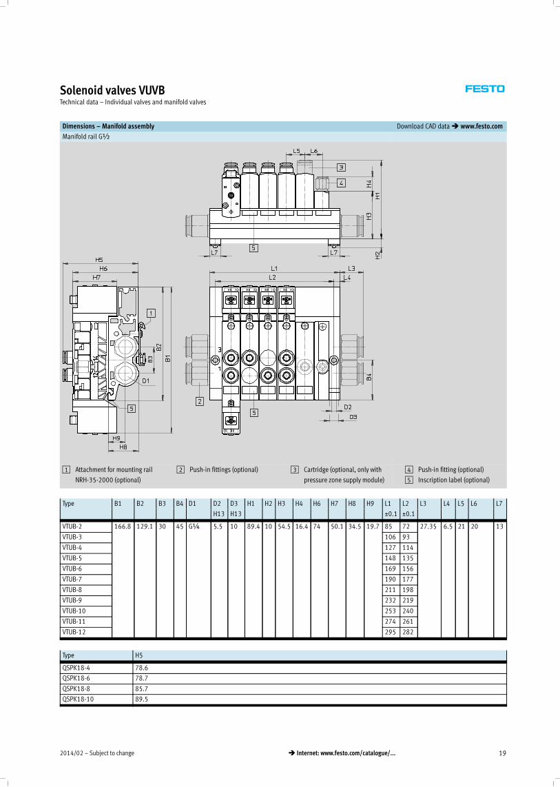
Dimensions – Manifold assembly Download CAD data� www.festo.com
Manifold rail G½
1 Attachment for mounting rail
NRH-35-2000 (optional)
2 Push-in fittings (optional) 3 Cartridge (optional, only with
pressure zone supply module)
4 Push-in fitting (optional)
5 Inscription label (optional)
Type B1 B2 B3 B4 D1 D2 D3 H1 H2 H3 H4 H6 H7 H8 H9 L1 L2 L3 L4 L5 L6 L7
H13 H13 _0.1 _0.1
VTUB-2 166.8 129.1 30 45 G¼ 5.5 10 89.4 10 54.5 16.4 74 50.1 34.5 19.7 85 72 27.35 6.5 21 20 13
VTUB-3 106 93
VTUB-4 127 114
VTUB-5 148 135
VTUB-6 169 156
VTUB-7 190 177
VTUB-8 211 198
VTUB-9 232 219
VTUB-10 253 240
VTUB-11 274 261
VTUB-12 295 282
Type H5
QSPK18-4 78.6
QSPK18-6 78.7
QSPK18-8 85.7
QSPK18-10 89.5
Subject to change – 2014/0220 � Internet: www.festo.com/catalogue/...
Solenoid valves VUVBTechnical data – Individual valves and manifold valves
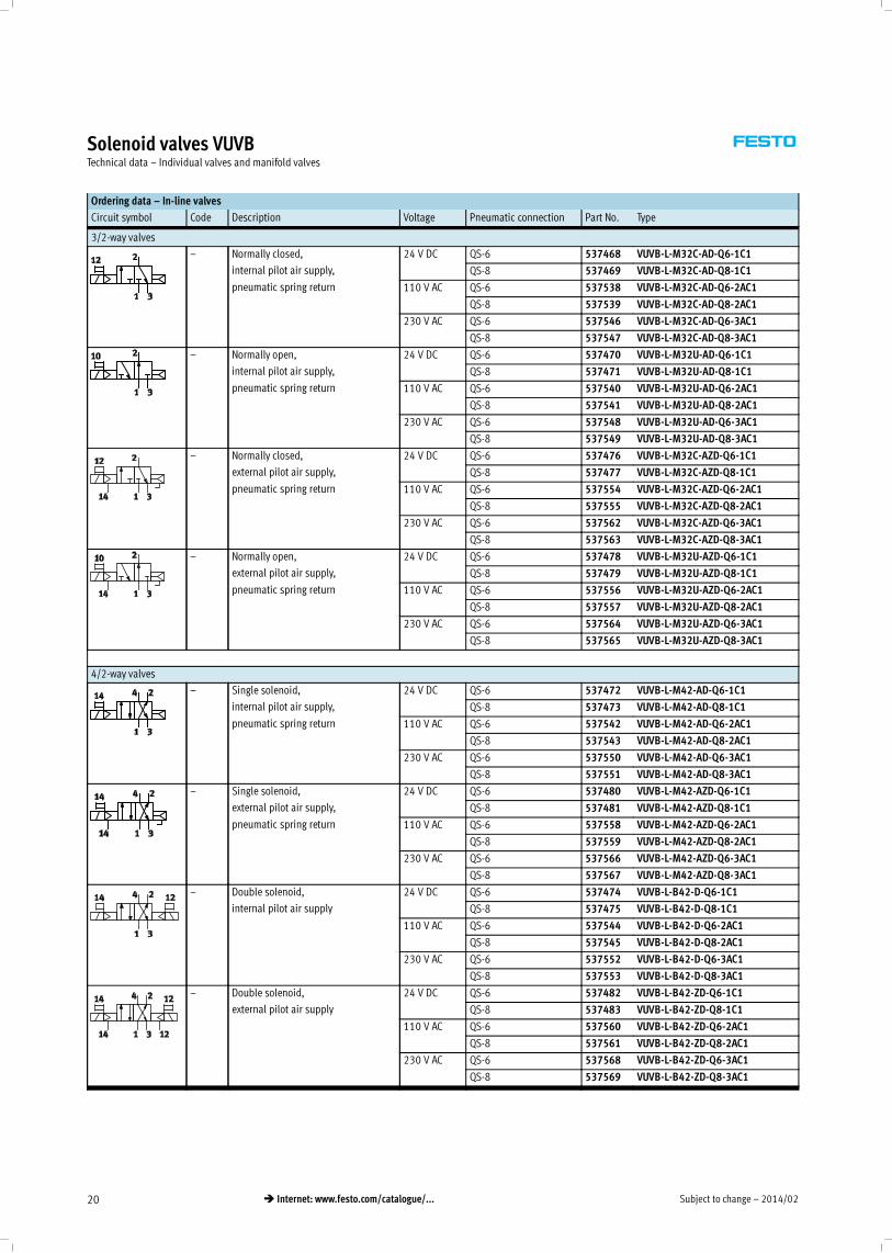
Ordering data – In-line valves
Circuit symbol Code Description Voltage Pneumatic connection Part No. Type
3/2-way valves
– Normally closed,
internal pilot air supply,
pneumatic spring return
24 V DC QS-6 537468 VUVB-L-M32C-AD-Q6-1C1
QS-8 537469 VUVB-L-M32C-AD-Q8-1C1
110 V AC QS-6 537538 VUVB-L-M32C-AD-Q6-2AC1
QS-8 537539 VUVB-L-M32C-AD-Q8-2AC1
230 V AC QS-6 537546 VUVB-L-M32C-AD-Q6-3AC1
QS-8 537547 VUVB-L-M32C-AD-Q8-3AC1
– Normally open,
internal pilot air supply,
pneumatic spring return
24 V DC QS-6 537470 VUVB-L-M32U-AD-Q6-1C1
QS-8 537471 VUVB-L-M32U-AD-Q8-1C1
110 V AC QS-6 537540 VUVB-L-M32U-AD-Q6-2AC1
QS-8 537541 VUVB-L-M32U-AD-Q8-2AC1
230 V AC QS-6 537548 VUVB-L-M32U-AD-Q6-3AC1
QS-8 537549 VUVB-L-M32U-AD-Q8-3AC1
– Normally closed,
external pilot air supply,
pneumatic spring return
24 V DC QS-6 537476 VUVB-L-M32C-AZD-Q6-1C1
QS-8 537477 VUVB-L-M32C-AZD-Q8-1C1
110 V AC QS-6 537554 VUVB-L-M32C-AZD-Q6-2AC1
QS-8 537555 VUVB-L-M32C-AZD-Q8-2AC1
230 V AC QS-6 537562 VUVB-L-M32C-AZD-Q6-3AC1
QS-8 537563 VUVB-L-M32C-AZD-Q8-3AC1
– Normally open,
external pilot air supply,
pneumatic spring return
24 V DC QS-6 537478 VUVB-L-M32U-AZD-Q6-1C1
QS-8 537479 VUVB-L-M32U-AZD-Q8-1C1
110 V AC QS-6 537556 VUVB-L-M32U-AZD-Q6-2AC1
QS-8 537557 VUVB-L-M32U-AZD-Q8-2AC1
230 V AC QS-6 537564 VUVB-L-M32U-AZD-Q6-3AC1
QS-8 537565 VUVB-L-M32U-AZD-Q8-3AC1
4/2-way valves
– Single solenoid,
internal pilot air supply,
pneumatic spring return
24 V DC QS-6 537472 VUVB-L-M42-AD-Q6-1C1
QS-8 537473 VUVB-L-M42-AD-Q8-1C1
110 V AC QS-6 537542 VUVB-L-M42-AD-Q6-2AC1
QS-8 537543 VUVB-L-M42-AD-Q8-2AC1
230 V AC QS-6 537550 VUVB-L-M42-AD-Q6-3AC1
QS-8 537551 VUVB-L-M42-AD-Q8-3AC1
– Single solenoid,
external pilot air supply,
pneumatic spring return
24 V DC QS-6 537480 VUVB-L-M42-AZD-Q6-1C1
QS-8 537481 VUVB-L-M42-AZD-Q8-1C1
110 V AC QS-6 537558 VUVB-L-M42-AZD-Q6-2AC1
QS-8 537559 VUVB-L-M42-AZD-Q8-2AC1
230 V AC QS-6 537566 VUVB-L-M42-AZD-Q6-3AC1
QS-8 537567 VUVB-L-M42-AZD-Q8-3AC1
– Double solenoid,
internal pilot air supply
24 V DC QS-6 537474 VUVB-L-B42-D-Q6-1C1
QS-8 537475 VUVB-L-B42-D-Q8-1C1
110 V AC QS-6 537544 VUVB-L-B42-D-Q6-2AC1
QS-8 537545 VUVB-L-B42-D-Q8-2AC1
230 V AC QS-6 537552 VUVB-L-B42-D-Q6-3AC1
QS-8 537553 VUVB-L-B42-D-Q8-3AC1
– Double solenoid,
external pilot air supply
24 V DC QS-6 537482 VUVB-L-B42-ZD-Q6-1C1
QS-8 537483 VUVB-L-B42-ZD-Q8-1C1
110 V AC QS-6 537560 VUVB-L-B42-ZD-Q6-2AC1
QS-8 537561 VUVB-L-B42-ZD-Q8-2AC1
230 V AC QS-6 537568 VUVB-L-B42-ZD-Q6-3AC1
QS-8 537569 VUVB-L-B42-ZD-Q8-3AC1
2014/02 – Subject to change 21� Internet: www.festo.com/catalogue/...
Solenoid valves VUVBTechnical data – Individual valves and manifold valves
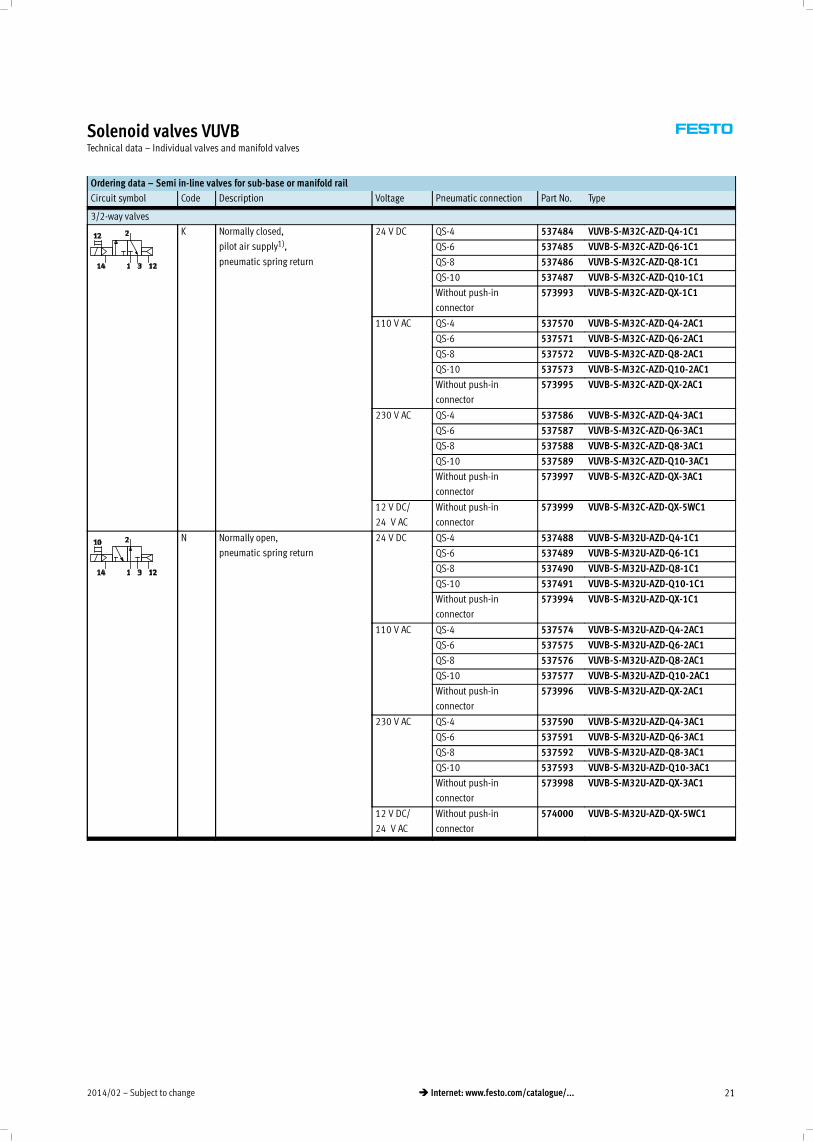
Ordering data – Semi in-line valves for sub-base or manifold rail
Circuit symbol Code Description Voltage Pneumatic connection Part No. Type
3/2-way valves
K Normally closed,
pilot air supply1),
pneumatic spring return
24 V DC QS-4 537484 VUVB-S-M32C-AZD-Q4-1C1
QS-6 537485 VUVB-S-M32C-AZD-Q6-1C1
QS-8 537486 VUVB-S-M32C-AZD-Q8-1C1
QS-10 537487 VUVB-S-M32C-AZD-Q10-1C1
Without push-in
connector
573993 VUVB-S-M32C-AZD-QX-1C1
110 V AC QS-4 537570 VUVB-S-M32C-AZD-Q4-2AC1
QS-6 537571 VUVB-S-M32C-AZD-Q6-2AC1
QS-8 537572 VUVB-S-M32C-AZD-Q8-2AC1
QS-10 537573 VUVB-S-M32C-AZD-Q10-2AC1
Without push-in
connector
573995 VUVB-S-M32C-AZD-QX-2AC1
230 V AC QS-4 537586 VUVB-S-M32C-AZD-Q4-3AC1
QS-6 537587 VUVB-S-M32C-AZD-Q6-3AC1
QS-8 537588 VUVB-S-M32C-AZD-Q8-3AC1
QS-10 537589 VUVB-S-M32C-AZD-Q10-3AC1
Without push-in
connector
573997 VUVB-S-M32C-AZD-QX-3AC1
12 V DC/
24 V AC
Without push-in
connector
573999 VUVB-S-M32C-AZD-QX-5WC1
N Normally open,
pneumatic spring return
24 V DC QS-4 537488 VUVB-S-M32U-AZD-Q4-1C1
QS-6 537489 VUVB-S-M32U-AZD-Q6-1C1
QS-8 537490 VUVB-S-M32U-AZD-Q8-1C1
QS-10 537491 VUVB-S-M32U-AZD-Q10-1C1
Without push-in
connector
573994 VUVB-S-M32U-AZD-QX-1C1
110 V AC QS-4 537574 VUVB-S-M32U-AZD-Q4-2AC1
QS-6 537575 VUVB-S-M32U-AZD-Q6-2AC1
QS-8 537576 VUVB-S-M32U-AZD-Q8-2AC1
QS-10 537577 VUVB-S-M32U-AZD-Q10-2AC1
Without push-in
connector
573996 VUVB-S-M32U-AZD-QX-2AC1
230 V AC QS-4 537590 VUVB-S-M32U-AZD-Q4-3AC1
QS-6 537591 VUVB-S-M32U-AZD-Q6-3AC1
QS-8 537592 VUVB-S-M32U-AZD-Q8-3AC1
QS-10 537593 VUVB-S-M32U-AZD-Q10-3AC1
Without push-in
connector
573998 VUVB-S-M32U-AZD-QX-3AC1
12 V DC/
24 V AC
Without push-in
connector
574000 VUVB-S-M32U-AZD-QX-5WC1
Subject to change – 2014/0222 � Internet: www.festo.com/catalogue/...
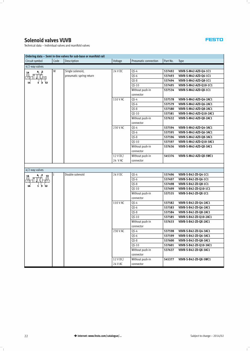
Solenoid valves VUVBTechnical data – Individual valves and manifold valves
Ordering data – Semi in-line valves for sub-base or manifold rail
Circuit symbol Code Description Voltage Pneumatic connection Part No. Type
4/2-way valves
M Single solenoid,
pneumatic spring return
24 V DC QS-4 537492 VUVB-S-M42-AZD-Q4-1C1
QS-6 537493 VUVB-S-M42-AZD-Q6-1C1
QS-8 537494 VUVB-S-M42-AZD-Q8-1C1
QS-10 537495 VUVB-S-M42-AZD-Q10-1C1
Without push-in
connector
537534 VUVB-S-M42-AZD-QX-1C1
110 V AC QS-4 537578 VUVB-S-M42-AZD-Q4-2AC1
QS-6 537579 VUVB-S-M42-AZD-Q6-2AC1
QS-8 537580 VUVB-S-M42-AZD-Q8-2AC1
QS-10 537581 VUVB-S-M42-AZD-Q10-2AC1
Without push-in
connector
537632 VUVB-S-M42-AZD-QX-2AC1
230 V AC QS-4 537594 VUVB-S-M42-AZD-Q4-3AC1
QS-6 537595 VUVB-S-M42-AZD-Q6-3AC1
QS-8 537596 VUVB-S-M42-AZD-Q8-3AC1
QS-10 537597 VUVB-S-M42-AZD-Q10-3AC1
Without push-in
connector
537636 VUVB-S-M42-AZD-QX-3AC1
12 V DC/
24 V AC
Without push-in
connector
545376 VUVB-S-M42-AZD-QX-5WC1
4/2-way valves
J Double solenoid 24 V DC QS-4 537496 VUVB-S-B42-ZD-Q4-1C1
QS-6 537497 VUVB-S-B42-ZD-Q6-1C1
QS-8 537498 VUVB-S-B42-ZD-Q8-1C1
QS-10 537499 VUVB-S-B42-ZD-Q10-1C1
Without push-in
connector
537535 VUVB-S-B42-ZD-QX-1C1
110 V AC QS-4 537582 VUVB-S-B42-ZD-Q4-2AC1
QS-6 537583 VUVB-S-B42-ZD-Q6-2AC1
QS-8 537584 VUVB-S-B42-ZD-Q8-2AC1
QS-10 537585 VUVB-S-B42-ZD-Q10-2AC1
Without push-in
connector
537633 VUVB-S-B42-ZD-QX-2AC1
230 V AC QS-4 537598 VUVB-S-B42-ZD-Q4-3AC1
QS-6 537599 VUVB-S-B42-ZD-Q6-3AC1
QS-8 537600 VUVB-S-B42-ZD-Q8-3AC1
QS-10 537601 VUVB-S-B42-ZD-Q10-3AC1
Without push-in
connector
537637 VUVB-S-B42-ZD-QX-3AC1
12 V DC/
24 V AC
Without push-in
connector
545377 VUVB-S-B42-ZD-QX-5WC1
2014/02 – Subject to change 23� Internet: www.festo.com/catalogue/...
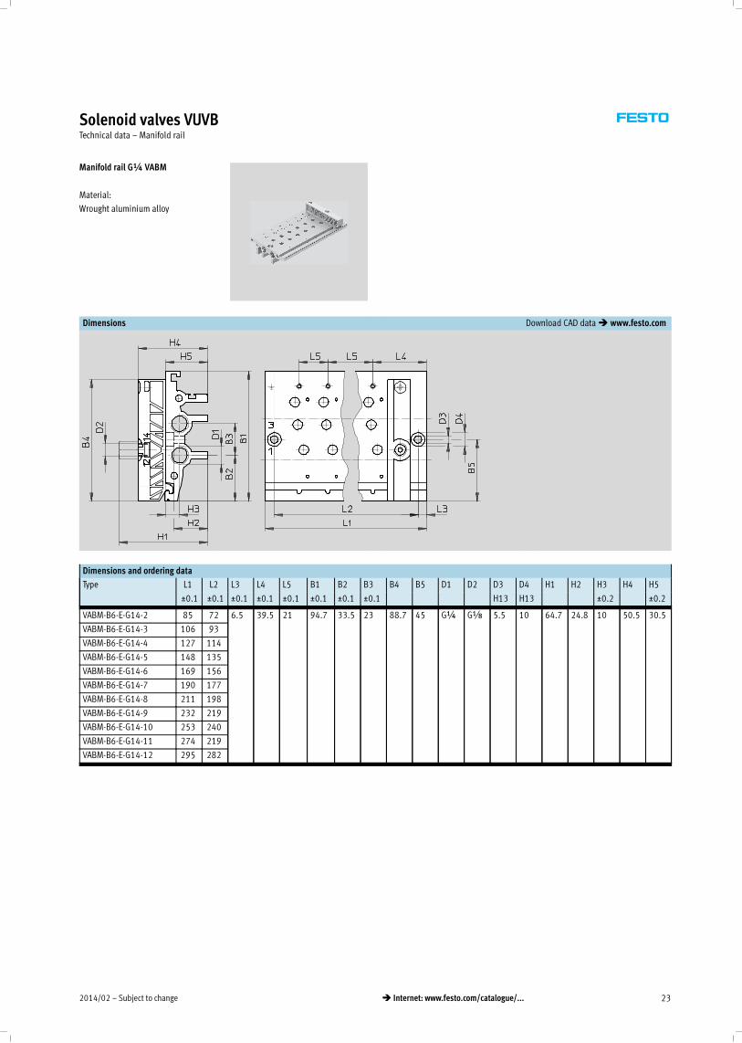
Solenoid valves VUVBTechnical data – Manifold rail
Manifold rail G¼ VABM
Material:
Wrought aluminium alloy
Dimensions Download CAD data� www.festo.com
Dimensions and ordering data
Type L1 L2 L3 L4 L5 B1 B2 B3 B4 B5 D1 D2 D3 D4 H1 H2 H3 H4 H5
_0.1 _0.1 _0.1 _0.1 _0.1 _0.1 _0.1 _0.1 H13 H13 _0.2 _0.2
VABM-B6-E-G14-2 85 72 6.5 39.5 21 94.7 33.5 23 88.7 45 G¼ GÁ 5.5 10 64.7 24.8 10 50.5 30.5
VABM-B6-E-G14-3 106 93
VABM-B6-E-G14-4 127 114
VABM-B6-E-G14-5 148 135
VABM-B6-E-G14-6 169 156
VABM-B6-E-G14-7 190 177
VABM-B6-E-G14-8 211 198
VABM-B6-E-G14-9 232 219
VABM-B6-E-G14-10 253 240
VABM-B6-E-G14-11 274 219
VABM-B6-E-G14-12 295 282
Subject to change – 2014/0224 � Internet: www.festo.com/catalogue/...
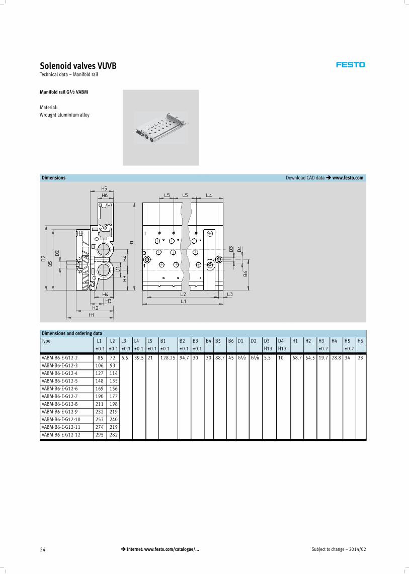
Solenoid valves VUVBTechnical data – Manifold rail
Manifold rail G½ VABM
Material:
Wrought aluminium alloy
Dimensions Download CAD data� www.festo.com
Dimensions and ordering data
Type L1 L2 L3 L4 L5 B1 B2 B3 B4 B5 B6 D1 D2 D3 D4 H1 H2 H3 H4 H5 H6
_0.1 _0.1 _0.1 _0.1 _0.1 _0.1 _0.1 _0.1 H13 H13 _0.2 _0.2
VABM-B6-E-G12-2 85 72 6.5 39.5 21 128.25 94.7 30 30 88.7 45 G½ GÁ 5.5 10 68.7 54.5 19.7 28.8 34 23
VABM-B6-E-G12-3 106 93
VABM-B6-E-G12-4 127 114
VABM-B6-E-G12-5 148 135
VABM-B6-E-G12-6 169 156
VABM-B6-E-G12-7 190 177
VABM-B6-E-G12-8 211 198
VABM-B6-E-G12-9 232 219
VABM-B6-E-G12-10 253 240
VABM-B6-E-G12-11 274 219
VABM-B6-E-G12-12 295 282
2014/02 – Subject to change 25� Internet: www.festo.com/catalogue/...
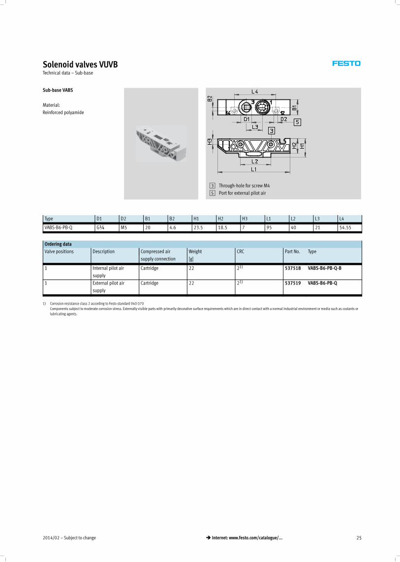
Solenoid valves VUVBTechnical data – Sub-base
Sub-base VABS
Material:
Reinforced polyamide
3 Through-hole for screw M4
5 Port for external pilot air
Type D1 D2 B1 B2 H1 H2 H3 L1 L2 L3 L4
VABS-B6-PB-Q G¼ M5 20 4.6 23.5 18.5 7 95 40 21 54.55
Ordering data
Valve positions Description Compressed air
supply connection
Weight CRC Part No. Type
[g]
1 Internal pilot air
supply
Cartridge 22 21) 537518 VABS-B6-PB-Q-B
1 External pilot air
supply
Cartridge 22 21) 537519 VABS-B6-PB-Q
1) Corrosion resistance class 2 according to Festo standard 940 070
Components subject to moderate corrosion stress. Externally visible parts with primarily decorative surface requirements which are in direct contact with a normal industrial environment or media such as coolants or
lubricating agents.
Subject to change – 2014/0226 � Internet: www.festo.com/catalogue/...
Valve terminals VTUBPeripherals overview
Overview – Valve terminal VTUB
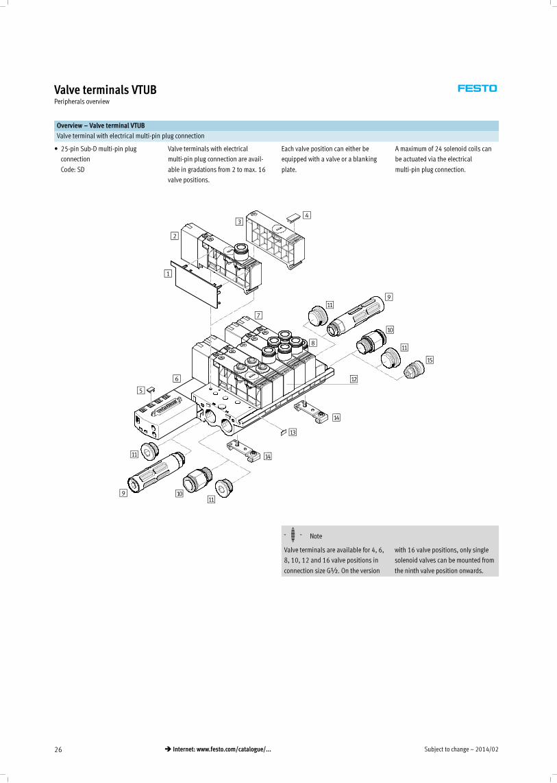
Valve terminal with electrical multi-pin plug connection
• 25-pin Sub-D multi-pin plug
connection
Code: SD
Valve terminals with electrical
multi-pin plug connection are avail-
able in gradations from 2 to max. 16
valve positions.
Each valve position can either be
equipped with a valve or a blanking
plate.
A maximum of 24 solenoid coils can
be actuated via the electrical
multi-pin plug connection.
1
2
34
5
6
9
aJ
aA
aB
8
9 aJ
aC
7
aD
aD
aA
aA
aA
aE
-H- Note
Valve terminals are available for 4, 6,
8, 10, 12 and 16 valve positions in
connection size G½. On the version
with 16 valve positions, only single
solenoid valves can be mounted from
the ninth valve position onwards.
2014/02 – Subject to change 27� Internet: www.festo.com/catalogue/...
Valve terminals VTUBPeripherals overview
Accessories
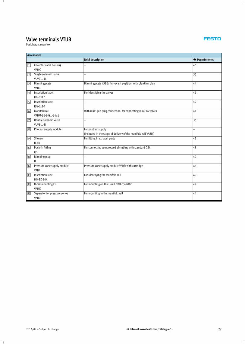
Brief description � Page/Internet
1 Cover for valve housing
VAMC
– 46
2 Single solenoid valve
VUVB-…-M
– 35
3 Blanking plate
VABB
Blanking plate VABB: for vacant position, with blanking plug 44
4 Inscription label
IBS-9x17
For identifying the valves 49
5 Inscription label
IBS-6x10
– 49
6 Manifold rail
VABM-B6-E-G…-6-M1
With multi-pin plug connection, for connecting max. 16 valves 41
7 Double solenoid valve
VUVB-…-B
– 35
8 Pilot air supply module For pilot air supply
(included in the scope of delivery of the manifold rail VABM)
–
9 Silencer
U, UC
For fitting in exhaust ports 49
aJ Push-in fitting
QS
For connecting compressed air tubing with standard O.D. 48
aA Blanking plug
B
– 49
aB Pressure zone supply module
VABF
Pressure zone supply module VABF: with cartridge 43
aC Inscription label
MH-BZ-80X
For identifying the manifold rail 49
aD H-rail mounting kit
VAME
For mounting on the H-rail NRH-35-2000 49
aE Separator for pressure zones
VABD
For mounting in the manifold rail 44
Subject to change – 2014/0228 � Internet: www.festo.com/catalogue/...
Valve terminals VTUBKey features
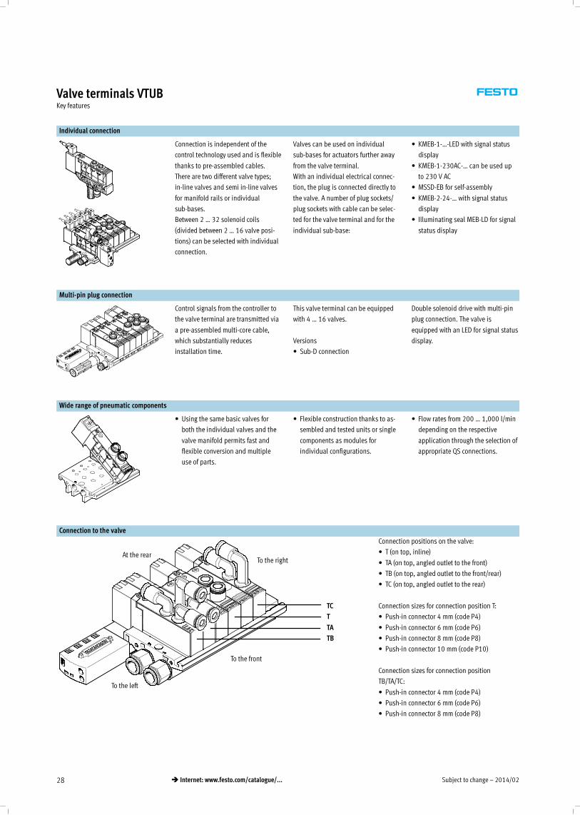
Individual connection
Connection is independent of the
control technology used and is flexible
thanks to pre-assembled cables.
There are two different valve types;
in-line valves and semi in-line valves
for manifold rails or individual
sub-bases.
Between 2 … 32 solenoid coils
(divided between 2 … 16 valve posi-
tions) can be selected with individual
connection.
Valves can be used on individual
sub-bases for actuators further away
from the valve terminal.
With an individual electrical connec-
tion, the plug is connected directly to
the valve. A number of plug sockets/
plug sockets with cable can be selec-
ted for the valve terminal and for the
individual sub-base:
• KMEB-1-…-LED with signal status
display
• KMEB-1-230AC-… can be used up
to 230 V AC
• MSSD-EB for self-assembly
• KMEB-2-24-… with signal status
display
• Illuminating seal MEB-LD for signal
status display
Multi-pin plug connection
Control signals from the controller to
the valve terminal are transmitted via
a pre-assembled multi-core cable,
which substantially reduces
installation time.
This valve terminal can be equipped
with 4 … 16 valves.
Versions
• Sub-D connection
Double solenoid drive with multi-pin
plug connection. The valve is
equipped with an LED for signal status
display.
Wide range of pneumatic components
• Using the same basic valves for
both the individual valves and the
valve manifold permits fast and
flexible conversion and multiple
use of parts.
• Flexible construction thanks to as-
sembled and tested units or single
components as modules for
individual configurations.
• Flow rates from 200 … 1,000 l/min
depending on the respective
application through the selection of
appropriate QS connections.
Connection to the valve
To the right
TC
T
TA
TB
To the front
At the rear
To the left
Connection positions on the valve:
• T (on top, inline)
• TA (on top, angled outlet to the front)
• TB (on top, angled outlet to the front/rear)
• TC (on top, angled outlet to the rear)
Connection sizes for connection position T:
• Push-in connector 4 mm (code P4)
• Push-in connector 6 mm (code P6)
• Push-in connector 8 mm (code P8)
• Push-in connector 10 mm (code P10)
Connection sizes for connection position
TB/TA/TC:
• Push-in connector 4 mm (code P4)
• Push-in connector 6 mm (code P6)
• Push-in connector 8 mm (code P8)
2014/02 – Subject to change 29� Internet: www.festo.com/catalogue/...
Valve terminals VTUBKey features – Pneumatic components
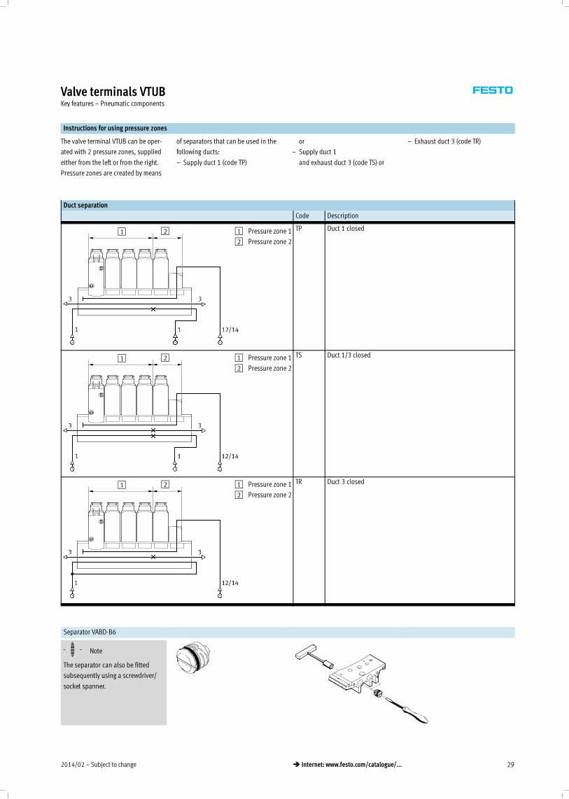
Instructions for using pressure zones
The valve terminal VTUB can be oper-
ated with 2 pressure zones, supplied
either from the left or from the right.
Pressure zones are created by means
of separators that can be used in the
following ducts:
– Supply duct 1 (code TP)
or
– Supply duct 1
and exhaust duct 3 (code TS) or
– Exhaust duct 3 (code TR)
Duct separation
Code Description
1 2 1 Pressure zone 1
2 Pressure zone 2
TP Duct 1 closed
1 2 1 Pressure zone 1
2 Pressure zone 2
TS Duct 1/3 closed
1 2 1 Pressure zone 1
2 Pressure zone 2
TR Duct 3 closed
Separator VABD-B6
-H- Note
The separator can also be fitted
subsequently using a screwdriver/
socket spanner.
Subject to change – 2014/0230 � Internet: www.festo.com/catalogue/...
Valve terminals VTUBKey features – Display and operation
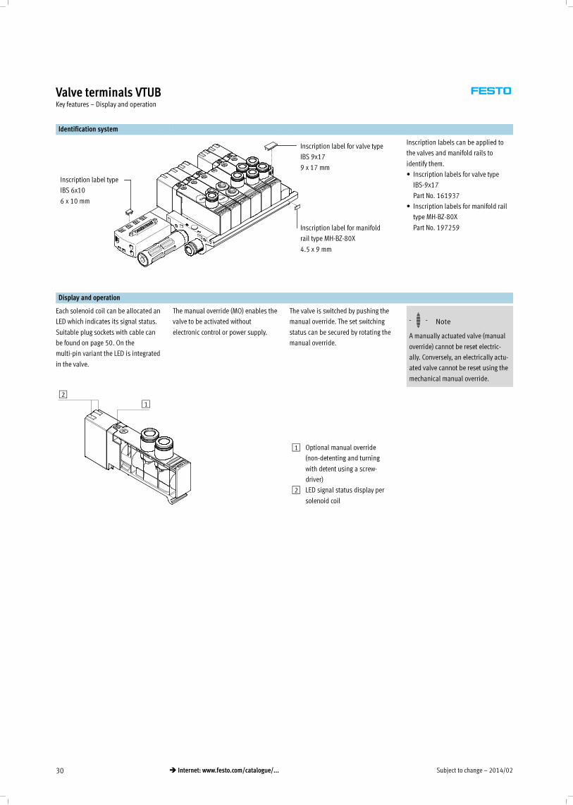
Identification system
Inscription label type
IBS 6x10
6 x 10 mm
Inscription label for valve type
IBS 9x17
9 x 17 mm
Inscription label for manifold
rail type MH-BZ-80X
4.5 x 9 mm
Inscription labels can be applied to
the valves and manifold rails to
identify them.
• Inscription labels for valve type
IBS-9x17
Part No. 161937
• Inscription labels for manifold rail
type MH-BZ-80X
Part No. 197259
Display and operation
Each solenoid coil can be allocated an
LED which indicates its signal status.
Suitable plug sockets with cable can
be found on page 50. On the
multi-pin variant the LED is integrated
in the valve.
The manual override (MO) enables the
valve to be activated without
electronic control or power supply.
The valve is switched by pushing the
manual override. The set switching
status can be secured by rotating the
manual override.
-H- Note
A manually actuated valve (manual
override) cannot be reset electric-
ally. Conversely, an electrically actu-
ated valve cannot be reset using the
mechanical manual override.
21
1 Optional manual override
(non-detenting and turning
with detent using a screw-
driver)
2 LED signal status display per
solenoid coil
2014/02 – Subject to change 31� Internet: www.festo.com/catalogue/...
Valve terminals VTUBKey features – Display and operation
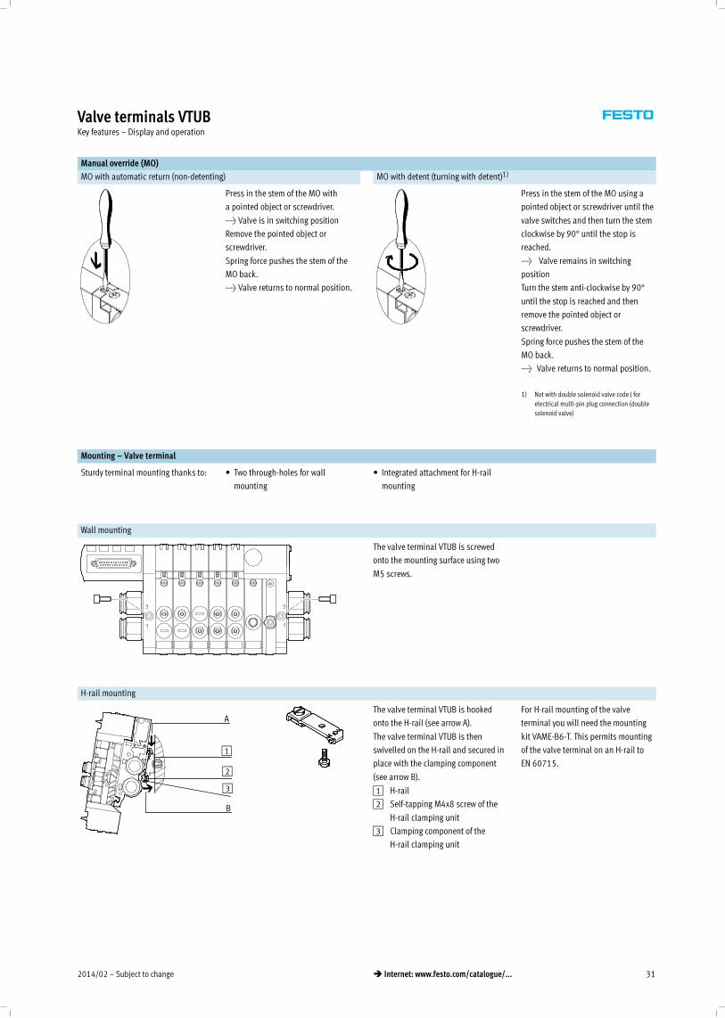
Manual override (MO)
MO with automatic return (non-detenting) MO with detent (turning with detent)1)
Press in the stem of the MO with
a pointed object or screwdriver.
> Valve is in switching position
Remove the pointed object or
screwdriver.
Spring force pushes the stem of the
MO back.
> Valve returns to normal position.
Press in the stem of the MO using a
pointed object or screwdriver until the
valve switches and then turn the stem
clockwise by 90° until the stop is
reached.
> Valve remains in switching
position
Turn the stem anti-clockwise by 90°
until the stop is reached and then
remove the pointed object or
screwdriver.
Spring force pushes the stem of the
MO back.
> Valve returns to normal position.
1) Not with double solenoid valve code J for
electrical multi-pin plug connection (double
solenoid valve)
Mounting – Valve terminal
Sturdy terminal mounting thanks to: • Two through-holes for wall
mounting
• Integrated attachment for H-rail
mounting
Wall mounting
The valve terminal VTUB is screwed
onto the mounting surface using two
M5 screws.
H-rail mounting
A
B
1
2
3
The valve terminal VTUB is hooked
onto the H-rail (see arrow A).
The valve terminal VTUB is then
swivelled on the H-rail and secured in
place with the clamping component
(see arrow B).
For H-rail mounting of the valve
terminal you will need the mounting
kit VAME-B6-T. This permits mounting
of the valve terminal on an H-rail to
EN 60715.
1 H-rail
2 Self-tapping M4x8 screw of the
H-rail clamping unit
3 Clamping component of the
H-rail clamping unit
Subject to change – 2014/0232 � Internet: www.festo.com/catalogue/...
Valve terminals VTUBKey features – Electrical components
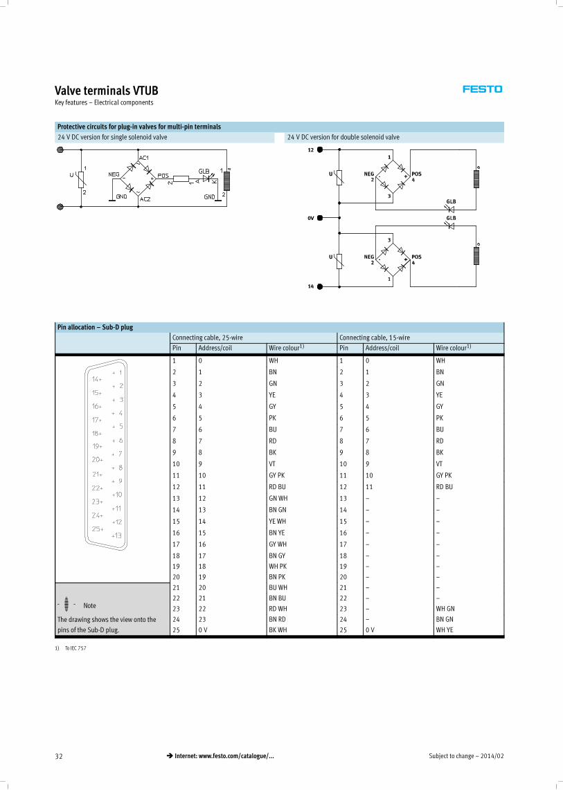
Protective circuits for plug-in valves for multi-pin terminals
24 V DC version for single solenoid valve 24 V DC version for double solenoid valve
Pin allocation – Sub-D plug
Connecting cable, 25-wire Connecting cable, 15-wire
Pin Address/coil Wire colour1) Pin Address/coil Wire colour1)
1 0 WH 1 0 WH
2 1 BN 2 1 BN
3 2 GN 3 2 GN
4 3 YE 4 3 YE
5 4 GY 5 4 GY
6 5 PK 6 5 PK
7 6 BU 7 6 BU
8 7 RD 8 7 RD
9 8 BK 9 8 BK
10 9 VT 10 9 VT
11 10 GY PK 11 10 GY PK
12 11 RD BU 12 11 RD BU
13 12 GN WH 13 – –
14 13 BN GN 14 – –
15 14 YE WH 15 – –
16 15 BN YE 16 – –
17 16 GY WH 17 – –
18 17 BN GY 18 – –
19 18 WH PK 19 – –
20 19 BN PK 20 – –
-H- Note
The drawing shows the view onto the
pins of the Sub-D plug.
21 20 BU WH 21 – –
22 21 BN BU 22 – –
23 22 RD WH 23 – WH GN
24 23 BN RD 24 – BN GN
25 0 V BK WH 25 0 V WH YE
1) To IEC 757
2014/02 – Subject to change 33� Internet: www.festo.com/catalogue/...
Valve terminals VTUBKey features – Instructions for use
Equipment
Operate system equipment with un-
lubricated compressed air if possible.
Festo valves and cylinders are de-
signed so that, if used as designated,
they will not require additional lubric-
ation and will still achieve a long
service life.
The quality of compressed air down-
stream of the compressor must corres-
pond to that of unlubricated com-
pressed air. If possible, do not operate
all of your system equipment with lub-
ricated compressed air. The lubricat-
ors should, where possible, always be
installed directly upstream of the ac-
tuator used.
Incorrect additional oil and too high
an oil content in the compressed air
reduce the service life of the valve
terminal.
Use Festo special oil OFSW-32 or the
alternatives listed in the Festo
catalogue (as specified in DIN 51524
HLP32; basic oil viscosity 32 CST
at 40 °C).
Bio-oils
When using bio-oils (oils which are
based on synthetic or native ester,
e.g. rapeseed oil methyl ester), the
maximum residual oil content of
0.1 mg/m3must not be exceeded
(see ISO 8573-1 Class 2).
Mineral oils
When using mineral oils (e.g. HLP oils
to DIN 51524, parts 1 to 3) or similar
oils based on poly-alpha-olefins
(PAO), the maximum residual oil con-
tent of 5 mg/m3must not be exceeded
(see ISO 8573-1 Class 4).
A higher residual oil content irrespect-
ive of the compressor oil cannot be
permitted, as the basic lubricant
would be flushed out over time.
Subject to change – 2014/0234 � Internet: www.festo.com/catalogue/...
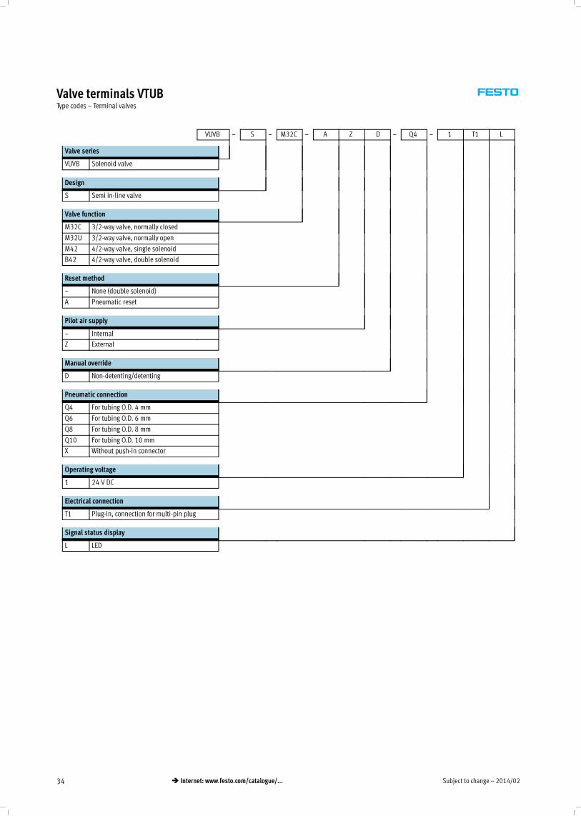
Valve terminals VTUBType codes – Terminal valves
VUVB – S – M32C – A Z D – Q4 – 1 T1 L
Valve series
VUVB Solenoid valve
Design
S Semi in-line valve
Valve function
M32C 3/2-way valve, normally closed
M32U 3/2-way valve, normally open
M42 4/2-way valve, single solenoid
B42 4/2-way valve, double solenoid
Reset method
– None (double solenoid)
A Pneumatic reset
Pilot air supply
– Internal
Z External
Manual override
D Non-detenting/detenting
Pneumatic connection
Q4 For tubing O.D. 4 mm
Q6 For tubing O.D. 6 mm
Q8 For tubing O.D. 8 mm
Q10 For tubing O.D. 10 mm
X Without push-in connector
Operating voltage
1 24 V DC
Electrical connection
T1 Plug-in, connection for multi-pin plug
Signal status display
L LED
2014/02 – Subject to change 35� Internet: www.festo.com/catalogue/...
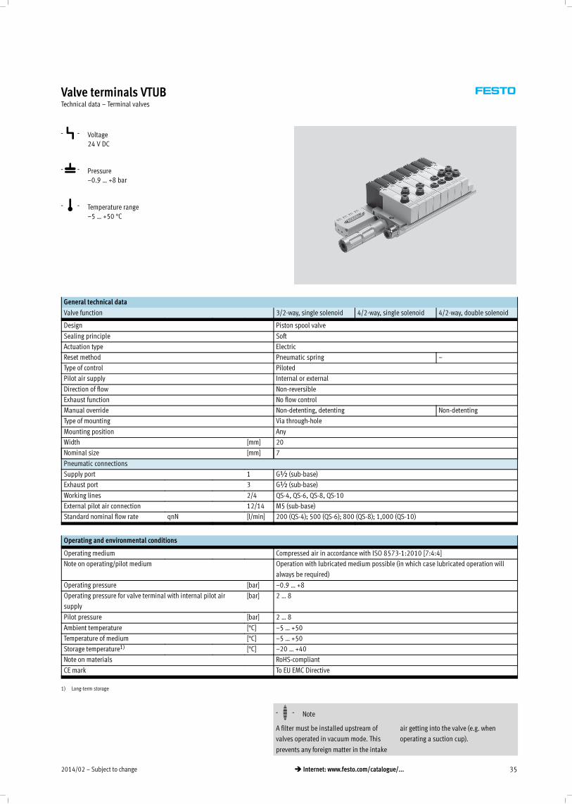
Valve terminals VTUBTechnical data – Terminal valves
-P- Voltage
24 V DC
-L- Pressure
–0.9 … +8 bar
-Q- Temperature range
–5 … +50 °C
General technical data
Valve function 3/2-way, single solenoid 4/2-way, single solenoid 4/2-way, double solenoid
Design Piston spool valve
Sealing principle Soft
Actuation type Electric
Reset method Pneumatic spring –
Type of control Piloted
Pilot air supply Internal or external
Direction of flow Non-reversible
Exhaust function No flow control
Manual override Non-detenting, detenting Non-detenting
Type of mounting Via through-hole
Mounting position Any
Width [mm] 20
Nominal size [mm] 7
Pneumatic connections
Supply port 1 G½ (sub-base)
Exhaust port 3 G½ (sub-base)
Working lines 2/4 QS-4, QS-6, QS-8, QS-10
External pilot air connection 12/14 M5 (sub-base)
Standard nominal flow rate qnN [l/min] 200 (QS-4); 500 (QS-6); 800 (QS-8); 1,000 (QS-10)
Operating and environmental conditions
Operating medium Compressed air in accordance with ISO 8573-1:2010 [7:4:4]
Note on operating/pilot medium Operation with lubricated medium possible (in which case lubricated operation will
always be required)
Operating pressure [bar] –0.9 … +8
Operating pressure for valve terminal with internal pilot air
supply
[bar] 2 … 8
Pilot pressure [bar] 2 … 8
Ambient temperature [°C] –5 … +50
Temperature of medium [°C] –5 … +50
Storage temperature1) [°C] –20 … +40
Note on materials RoHS-compliant
CE mark To EU EMC Directive*
1) Long-term storage
-H- Note
A filter must be installed upstream of
valves operated in vacuum mode. This
prevents any foreign matter in the intake
air getting into the valve (e.g. when
operating a suction cup).
Subject to change – 2014/0236 � Internet: www.festo.com/catalogue/...
Valve terminals VTUBTechnical data – Terminal valves
Electrical data
Valve function 3/2-way, single solenoid 4/2-way, single solenoid 4/2-way, double solenoid
Electrical connection Socket for multi-pin plug
Nominal operating voltage [V DC] 24
Permissible voltage fluctuations ±10%
Electrical power consumption [W] 1.5 1.5 3.3 (following a current
reduction 0.1)
Protection class to EN 60529 IP65
Valve switching times [ms]
Valve function 3/2-way, single solenoid 4/2-way, single solenoid 4/2-way, double solenoid
On 20 20 –
Off 20 20 –
Changeover – – 20
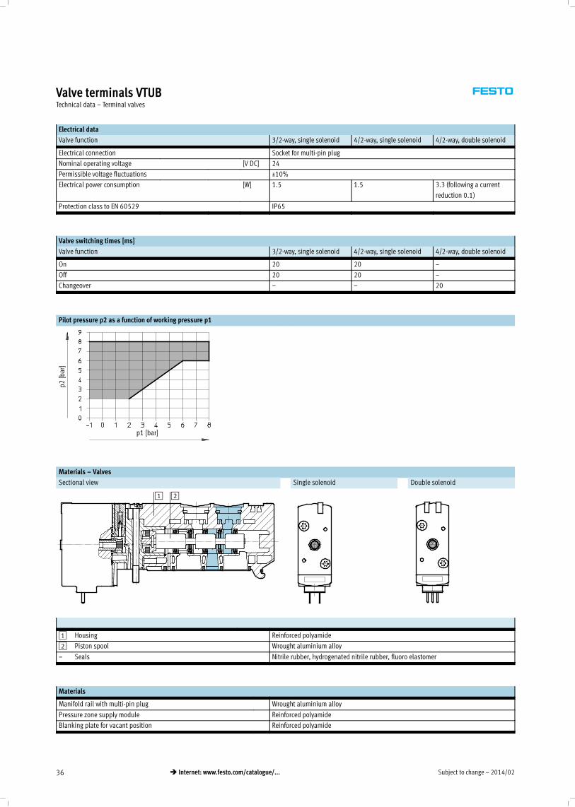
Pilot pressure p2 as a function of working pressure p1
p2[bar]
p1 [bar]
Materials – Valves
Sectional view Single solenoid Double solenoid
1 2
1 Housing Reinforced polyamide
2 Piston spool Wrought aluminium alloy
– Seals Nitrile rubber, hydrogenated nitrile rubber, fluoro elastomer
Materials
Manifold rail with multi-pin plug Wrought aluminium alloy
Pressure zone supply module Reinforced polyamide
Blanking plate for vacant position Reinforced polyamide
2014/02 – Subject to change 37� Internet: www.festo.com/catalogue/...
Valve terminals VTUBTechnical data – Terminal valves
Product weight
Approx. weight [g]
Manifold rail with multi-pin plug
• 4 valve positions
• 6 valve positions
• 8 valve positions
• 10 valve positions
• 12 valve positions
• 16 valve positions
690
915
1,150
1,380
1,620
2,100
Pressure zone supply module 30
Valves
• Single solenoid (code K, N, M)
• Double solenoid (code J)
150
220
Blanking plate for vacant position 25
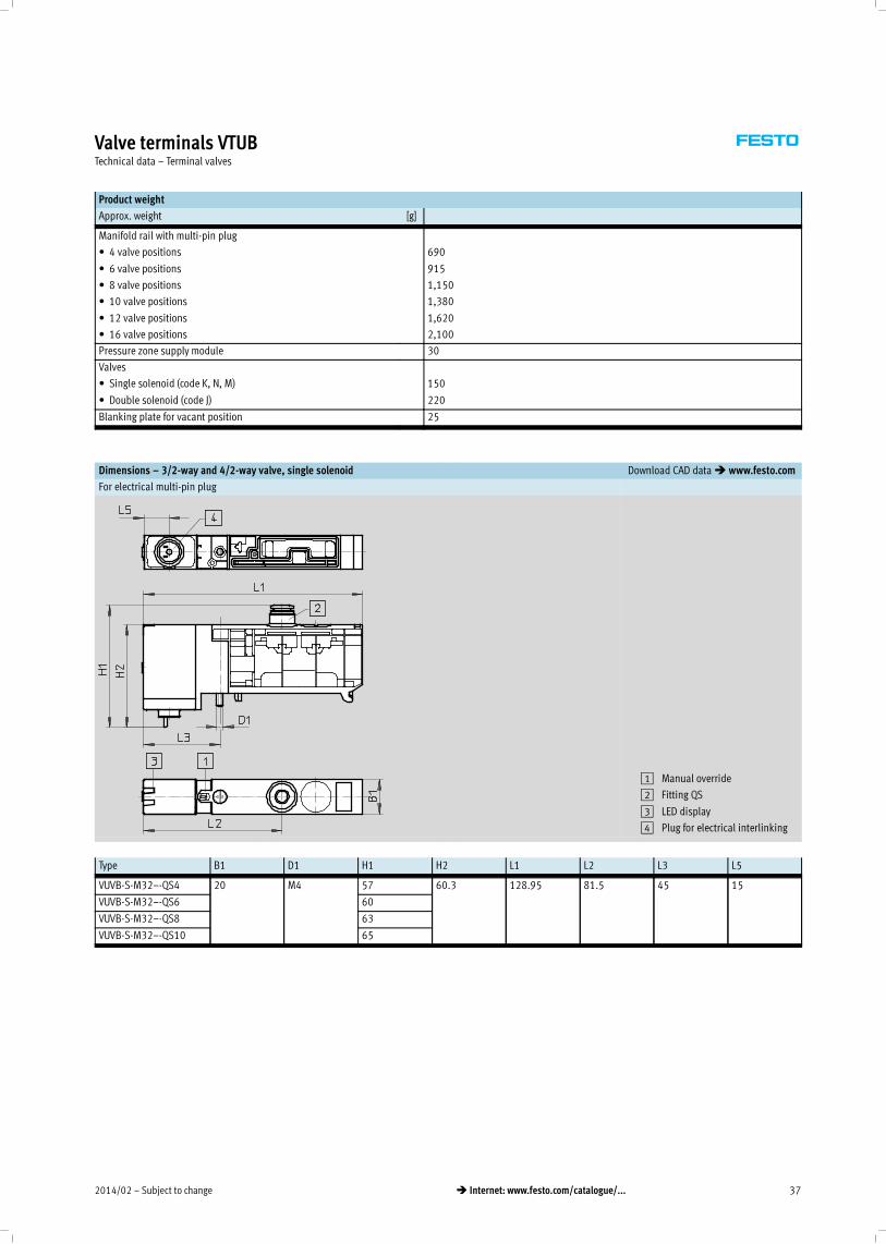
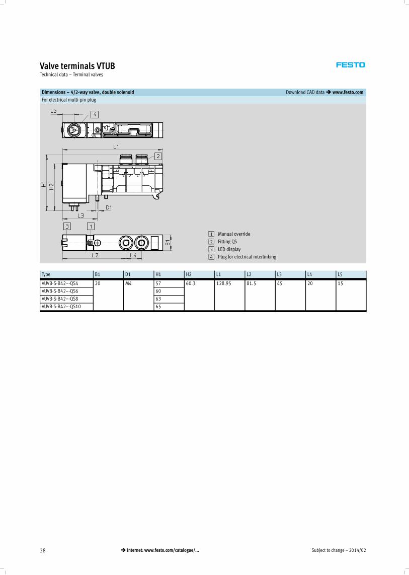
Dimensions – 3/2-way and 4/2-way valve, single solenoid Download CAD data� www.festo.com
For electrical multi-pin plug
1 Manual override
2 Fitting QS
3 LED display
4 Plug for electrical interlinking
Type B1 D1 H1 H2 L1 L2 L3 L5
VUVB-S-M32–-QS4 20 M4 57 60.3 128.95 81.5 45 15
VUVB-S-M32–-QS6 60
VUVB-S-M32–-QS8 63
VUVB-S-M32–-QS10 65
Subject to change – 2014/0238 � Internet: www.festo.com/catalogue/...
Valve terminals VTUBTechnical data – Terminal valves
Dimensions – 4/2-way valve, double solenoid Download CAD data� www.festo.com
For electrical multi-pin plug
1 Manual override
2 Fitting QS
3 LED display
4 Plug for electrical interlinking
Type B1 D1 H1 H2 L1 L2 L3 L4 L5
VUVB-S-B42–-QS4 20 M4 57 60.3 128.95 81.5 45 20 15
VUVB-S-B42–-QS6 60
VUVB-S-B42–-QS8 63
VUVB-S-B42–-QS10 65
2014/02 – Subject to change 39� Internet: www.festo.com/catalogue/...
Valve terminals VTUBTechnical data – Terminal valves
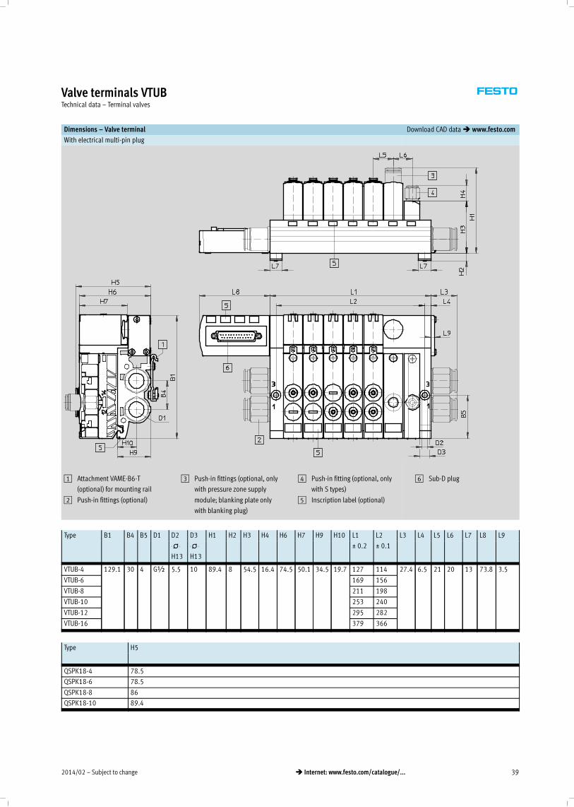
Dimensions – Valve terminal Download CAD data� www.festo.com
With electrical multi-pin plug
1 Attachment VAME-B6-T
(optional) for mounting rail
2 Push-in fittings (optional)
3 Push-in fittings (optional, only
with pressure zone supply
module; blanking plate only
with blanking plug)
4 Push-in fitting (optional, only
with S types)
5 Inscription label (optional)
6 Sub-D plug
Type B1 B4 B5 D1 D2 D3 H1 H2 H3 H4 H6 H7 H9 H10 L1 L2 L3 L4 L5 L6 L7 L8 L9
-N-
H13
-N-
H13
_ 0.2 _ 0.1
,
VTUB-4 129.1 30 4 G½ 5.5 10 89.4 8 54.5 16.4 74.5 50.1 34.5 19.7 127 114 27.4 6.5 21 20 13 73.8 3.5
VTUB-6 169 156
VTUB-8 211 198
VTUB-10 253 240
VTUB-12 295 282
VTUB-16 379 366
Type H5
QSPK18-4 78.5
QSPK18-6 78.5
QSPK18-8 86
QSPK18-10 89.4
Subject to change – 2014/0240 � Internet: www.festo.com/catalogue/...
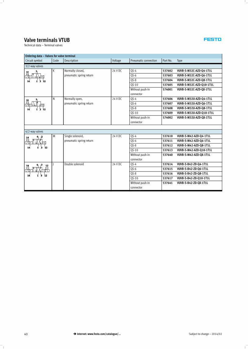
Valve terminals VTUBTechnical data – Terminal valves
Ordering data – Valves for valve terminal
Circuit symbol Code Description Voltage Pneumatic connection Part No. Type
3/2-way valves
K Normally closed,
pneumatic spring return
24 V DC QS-4 537602 VUVB-S-M32C-AZD-Q4-1T1L
QS-6 537603 VUVB-S-M32C-AZD-Q6-1T1L
QS-8 537604 VUVB-S-M32C-AZD-Q8-1T1L
QS-10 537605 VUVB-S-M32C-AZD-Q10-1T1L
Without push-in
connector
574001 VUVB-S-M32C-AZD-QX-1T1L
N Normally open,
pneumatic spring return
24 V DC QS-4 537606 VUVB-S-M32U-AZD-Q4-1T1L
QS-6 537607 VUVB-S-M32U-AZD-Q6-1T1L
QS-8 537608 VUVB-S-M32U-AZD-Q8-1T1L
QS-10 537609 VUVB-S-M32U-AZD-Q10-1T1L
Without push-in
connector
574002 VUVB-S-M32U-AZD-QX-1T1L
4/2-way valves
M Single solenoid,
pneumatic spring return
24 V DC QS-4 537610 VUVB-S-M42-AZD-Q4-1T1L
QS-6 537611 VUVB-S-M42-AZD-Q6-1T1L
QS-8 537612 VUVB-S-M42-AZD-Q8-1T1L
QS-10 537613 VUVB-S-M42-AZD-Q10-1T1L
Without push-in
connector
537640 VUVB-S-M42-AZD-QX-1T1L
J Double solenoid 24 V DC QS-4 537614 VUVB-S-B42-ZD-Q4-1T1L
QS-6 537615 VUVB-S-B42-ZD-Q6-1T1L
QS-8 537616 VUVB-S-B42-ZD-Q8-1T1L
QS-10 537617 VUVB-S-B42-ZD-Q10-1T1L
Without push-in
connector
537641 VUVB-S-B42-ZD-QX-1T1L
2014/02 – Subject to change 41� Internet: www.festo.com/catalogue/...
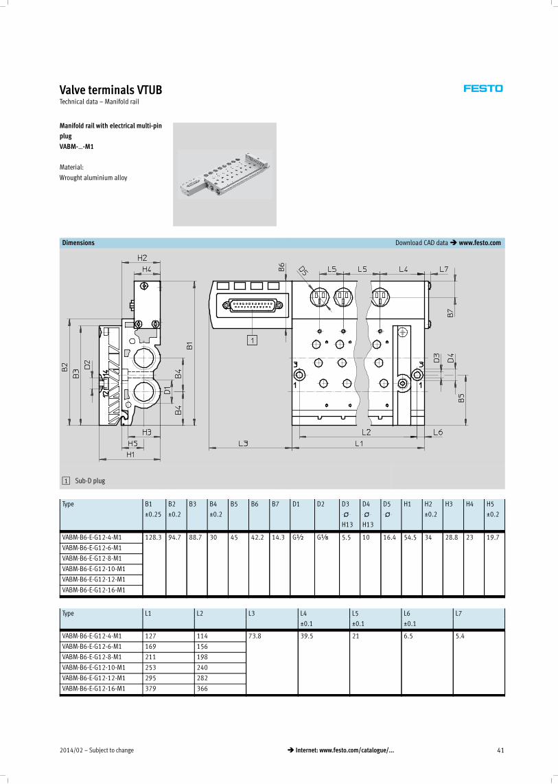
Valve terminals VTUBTechnical data – Manifold rail
Manifold rail with electrical multi-pin
plug
VABM-…-M1
Material:
Wrought aluminium alloy
Dimensions Download CAD data� www.festo.com
1 Sub-D plug
Type B1 B2 B3 B4 B5 B6 B7 D1 D2 D3 D4 D5 H1 H2 H3 H4 H5
_0.25 _0.2 _0.2 -N-
H13
-N-
H13
-N- _0.2 _0.2
,
VABM-B6-E-G12-4-M1 128.3 94.7 88.7 30 45 42.2 14.3 G½ GÁ 5.5 10 16.4 54.5 34 28.8 23 19.7
VABM-B6-E-G12-6-M1
VABM-B6-E-G12-8-M1
VABM-B6-E-G12-10-M1
VABM-B6-E-G12-12-M1
VABM-B6-E-G12-16-M1
Type L1 L2 L3 L4 L5 L6 L7
_0.1 _0.1 _0.1
VABM-B6-E-G12-4-M1 127 114 73.8 39.5 21 6.5 5.4
VABM-B6-E-G12-6-M1 169 156
VABM-B6-E-G12-8-M1 211 198
VABM-B6-E-G12-10-M1 253 240
VABM-B6-E-G12-12-M1 295 282
VABM-B6-E-G12-16-M1 379 366
Subject to change – 2014/0242 � Internet: www.festo.com/catalogue/...
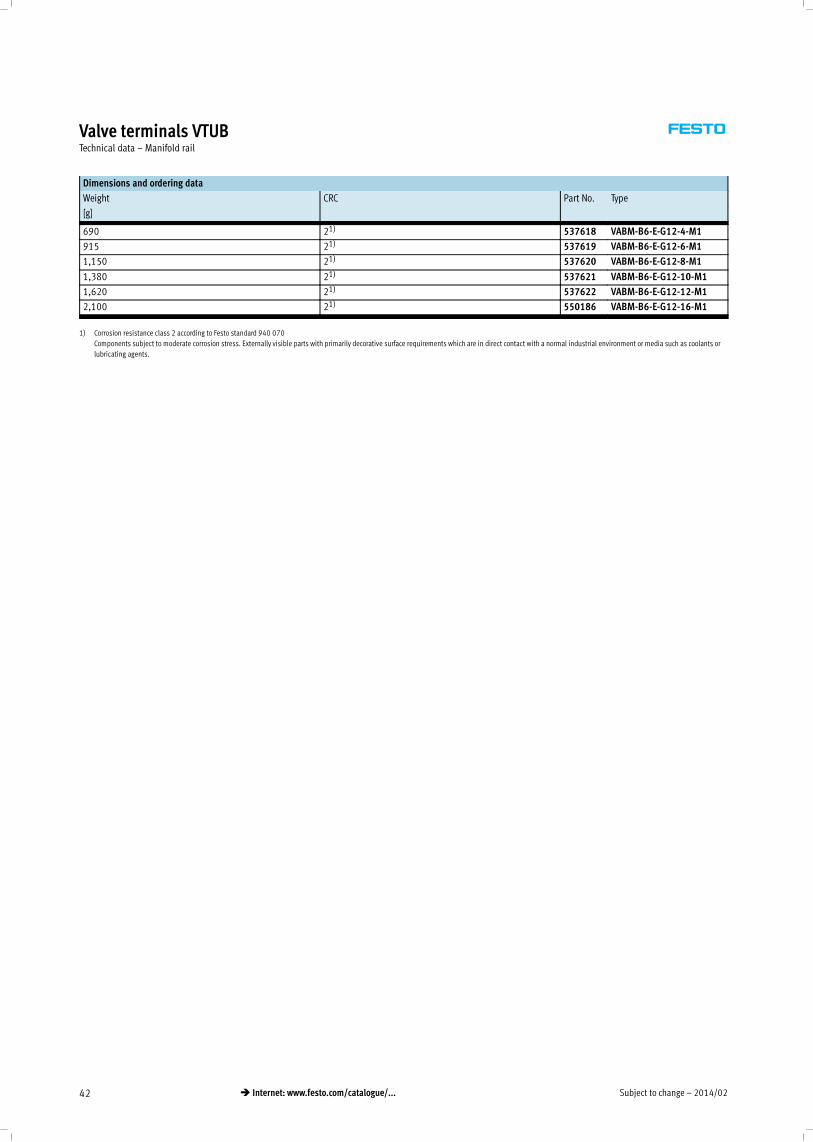
Valve terminals VTUBTechnical data – Manifold rail
Dimensions and ordering data
Weight CRC Part No. Type
[g]
690 21) 537618 VABM-B6-E-G12-4-M1
915 21) 537619 VABM-B6-E-G12-6-M1
1,150 21) 537620 VABM-B6-E-G12-8-M1
1,380 21) 537621 VABM-B6-E-G12-10-M1
1,620 21) 537622 VABM-B6-E-G12-12-M1
2,100 21) 550186 VABM-B6-E-G12-16-M1
1) Corrosion resistance class 2 according to Festo standard 940 070
Components subject to moderate corrosion stress. Externally visible parts with primarily decorative surface requirements which are in direct contact with a normal industrial environment or media such as coolants or
lubricating agents.
2014/02 – Subject to change 43� Internet: www.festo.com/catalogue/...
Solenoid valves VUVB/valve terminals VTUBAccessories
Cover for valve housing VAMC
Material:
Polyamide
Ordering data
CRC Part No. Type
21) 537512 VAMC-B6-C
1) Corrosion resistance class 2 according to Festo standard 940 070
Components subject to moderate corrosion stress. Externally visible parts with primarily decorative surface requirements which are in direct contact with a normal industrial environment or media such as coolants or
lubricating agents.
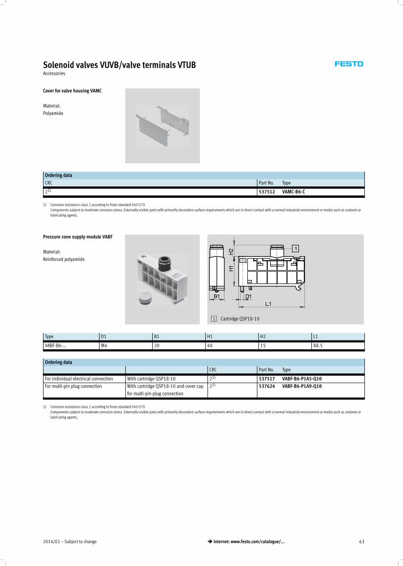
Pressure zone supply module VABF
Material:
Reinforced polyamide
1 Cartridge QSP18-10
Type D1 B1 H1 H2 L1
VABF-B6-… M4 20 40 15 88.5
Ordering data
CRC Part No. Type
For individual electrical connection With cartridge QSP18-10 21) 537517 VABF-B6-P1A5-Q10
For multi-pin plug connection With cartridge QSP18-10 and cover cap
for multi-pin plug connection
21) 537624 VABF-B6-P1A9-Q10
1) Corrosion resistance class 2 according to Festo standard 940 070
Components subject to moderate corrosion stress. Externally visible parts with primarily decorative surface requirements which are in direct contact with a normal industrial environment or media such as coolants or
lubricating agents.
Subject to change – 2014/0244 � Internet: www.festo.com/catalogue/...
Solenoid valves VUVB/valve terminals VTUBAccessories
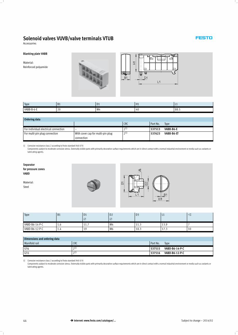
Blanking plate VABB
Material:
Reinforced polyamide
Type B1 D1 H1 L1
VABB-B-6-E 20 M4 40 88.5
Ordering data
CRC Part No. Type
For individual electrical connection – 21) 537513 VABB-B6-E
For multi-pin plug connection With cover cap for multi-pin plug
connection
21) 537623 VABB-B6-ET
1) Corrosion resistance class 2 according to Festo standard 940 070
Components subject to moderate corrosion stress. Externally visible parts with primarily decorative surface requirements which are in direct contact with a normal industrial environment or media such as coolants or
lubricating agents.
Separator
for pressure zones
VABD
Material:
Steel
Type B1 D1
∅
D2
∅
D3 L1 ß
VABD-B6-14-P-C 1.6 11.7 M4 11.3 13.9 7
VABD-B6-12-P-C 1.4 19 M6 18.3 17.3 10
Dimensions and ordering data
Manifold rail CRC Part No. Type
G¼ 21) 537515 VABD-B6-14-P-C
G½ 21) 537516 VABD-B6-12-P-C
1) Corrosion resistance class 2 according to Festo standard 940 070
Components subject to moderate corrosion stress. Externally visible parts with primarily decorative surface requirements which are in direct contact with a normal industrial environment or media such as coolants or
lubricating agents.
2014/02 – Subject to change 45� Internet: www.festo.com/catalogue/...
Solenoid valves VUVB/valve terminals VTUBAccessories
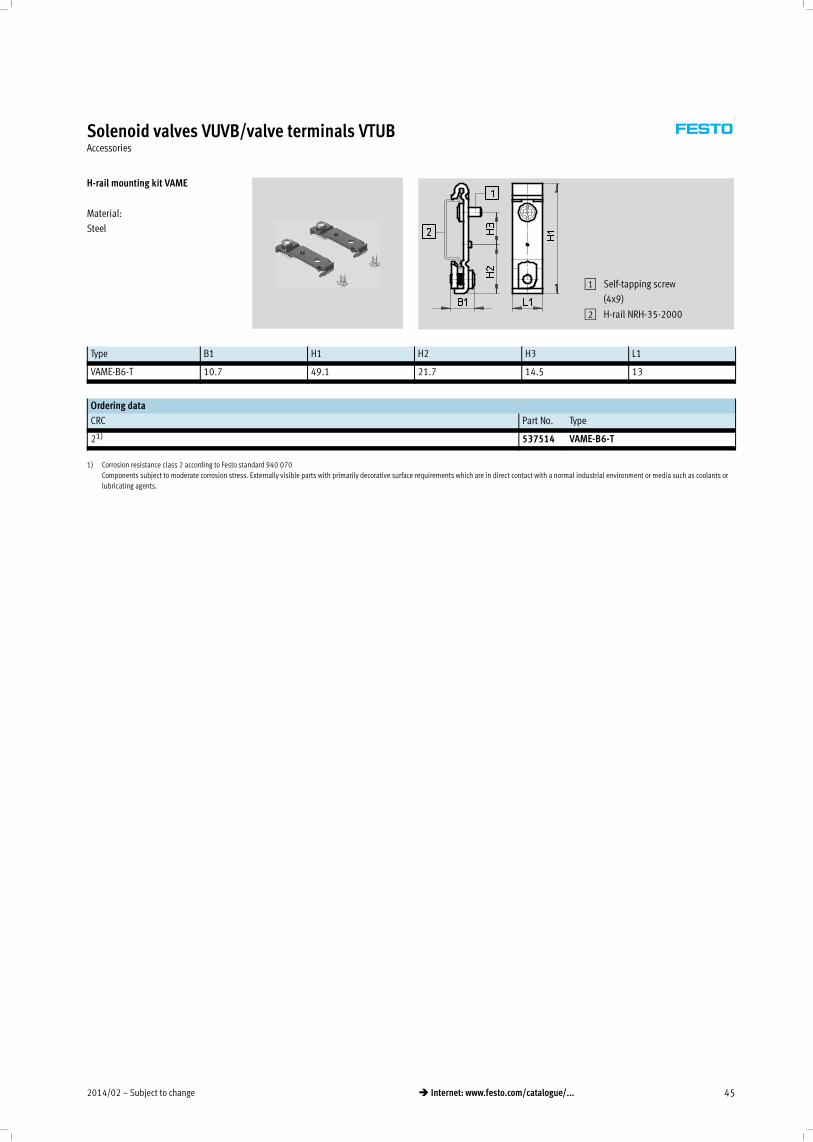
H-rail mounting kit VAME
Material:
Steel
1 Self-tapping screw
(4x9)
2 H-rail NRH-35-2000
Type B1 H1 H2 H3 L1
VAME-B6-T 10.7 49.1 21.7 14.5 13
Ordering data
CRC Part No. Type
21) 537514 VAME-B6-T
1) Corrosion resistance class 2 according to Festo standard 940 070
Components subject to moderate corrosion stress. Externally visible parts with primarily decorative surface requirements which are in direct contact with a normal industrial environment or media such as coolants or
lubricating agents.
Subject to change – 2014/0246 � Internet: www.festo.com/catalogue/...
Solenoid valves VUVB/valve terminals VTUBAccessories
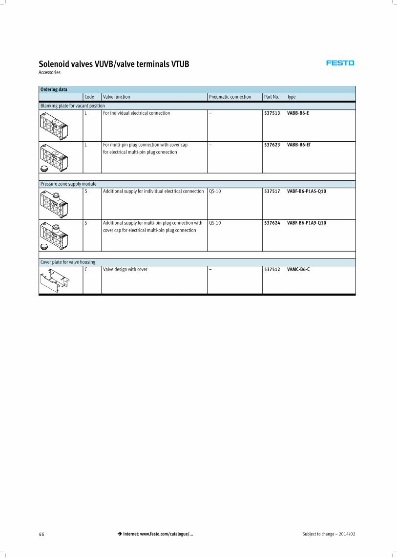
Ordering data
Code Valve function Pneumatic connection Part No. Type
Blanking plate for vacant position
L For individual electrical connection – 537513 VABB-B6-E
L For multi-pin plug connection with cover cap
for electrical multi-pin plug connection
– 537623 VABB-B6-ET
Pressure zone supply module
S Additional supply for individual electrical connection QS-10 537517 VABF-B6-P1A5-Q10
S Additional supply for multi-pin plug connection with
cover cap for electrical multi-pin plug connection
QS-10 537624 VABF-B6-P1A9-Q10
Cover plate for valve housing
C Valve design with cover – 537512 VAMC-B6-C
2014/02 – Subject to change 47� Internet: www.festo.com/catalogue/...
Solenoid valves VUVB/valve terminals VTUBAccessories
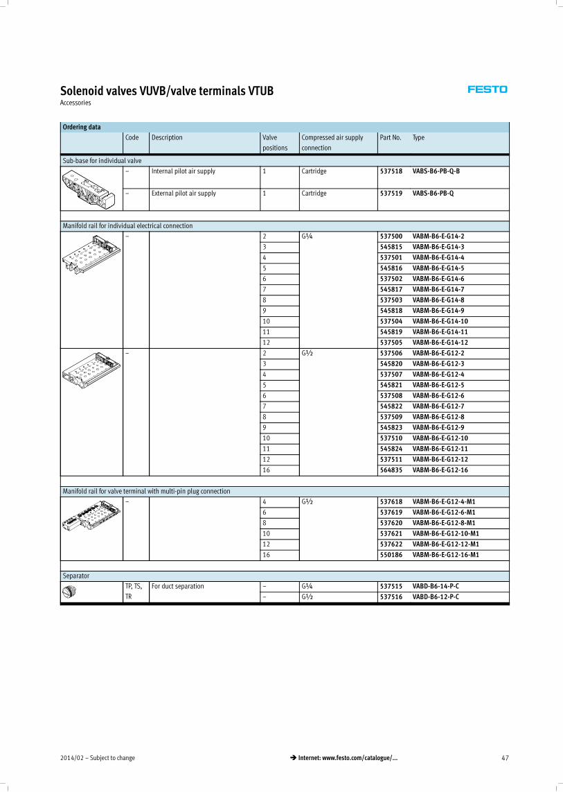
Ordering data
Code Description Valve
positions
Compressed air supply
connection
Part No. Type
Sub-base for individual valve
– Internal pilot air supply 1 Cartridge 537518 VABS-B6-PB-Q-B
– External pilot air supply 1 Cartridge 537519 VABS-B6-PB-Q
Manifold rail for individual electrical connection
– 2 G¼ 537500 VABM-B6-E-G14-2
3 545815 VABM-B6-E-G14-3
4 537501 VABM-B6-E-G14-4
5 545816 VABM-B6-E-G14-5
6 537502 VABM-B6-E-G14-6
7 545817 VABM-B6-E-G14-7
8 537503 VABM-B6-E-G14-8
9 545818 VABM-B6-E-G14-9
10 537504 VABM-B6-E-G14-10
11 545819 VABM-B6-E-G14-11
12 537505 VABM-B6-E-G14-12
– 2 G½ 537506 VABM-B6-E-G12-2
3 545820 VABM-B6-E-G12-3
4 537507 VABM-B6-E-G12-4
5 545821 VABM-B6-E-G12-5
6 537508 VABM-B6-E-G12-6
7 545822 VABM-B6-E-G12-7
8 537509 VABM-B6-E-G12-8
9 545823 VABM-B6-E-G12-9
10 537510 VABM-B6-E-G12-10
11 545824 VABM-B6-E-G12-11
12 537511 VABM-B6-E-G12-12
16 564835 VABM-B6-E-G12-16
Manifold rail for valve terminal with multi-pin plug connection
– 4 G½ 537618 VABM-B6-E-G12-4-M1
6 537619 VABM-B6-E-G12-6-M1
8 537620 VABM-B6-E-G12-8-M1
10 537621 VABM-B6-E-G12-10-M1
12 537622 VABM-B6-E-G12-12-M1
16 550186 VABM-B6-E-G12-16-M1
Separator
TP, TS,
TR
For duct separation – G¼ 537515 VABD-B6-14-P-C
– G½ 537516 VABD-B6-12-P-C
Subject to change – 2014/0248 � Internet: www.festo.com/catalogue/...
Solenoid valves VUVB/valve terminals VTUBAccessories
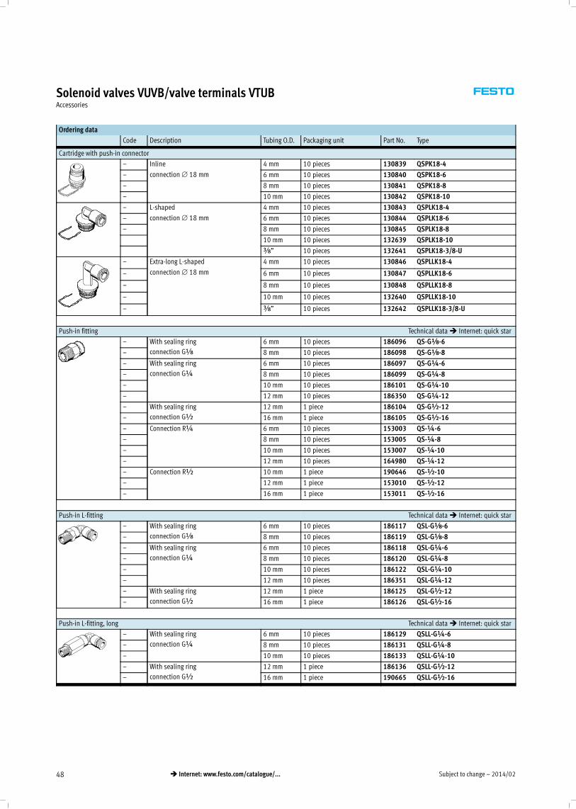
Ordering data
Code Description Tubing O.D. Packaging unit Part No. Type
Cartridge with push-in connector
– Inline
connection∅ 18 mm
4 mm 10 pieces 130839 QSPK18-4
– 6 mm 10 pieces 130840 QSPK18-6
– 8 mm 10 pieces 130841 QSPK18-8
– 10 mm 10 pieces 130842 QSPK18-10
– L-shaped
connection∅ 18 mm
4 mm 10 pieces 130843 QSPLK18-4
– 6 mm 10 pieces 130844 QSPLK18-6
– 8 mm 10 pieces 130845 QSPLK18-8
10 mm 10 pieces 132639 QSPLK18-10
y” 10 pieces 132641 QSPLK18-3/8-U
– Extra-long L-shaped
connection∅ 18 mm
4 mm 10 pieces 130846 QSPLLK18-4
– 6 mm 10 pieces 130847 QSPLLK18-6
– 8 mm 10 pieces 130848 QSPLLK18-8
– 10 mm 10 pieces 132640 QSPLLK18-10
– y” 10 pieces 132642 QSPLLK18-3/8-U
Push-in fitting Technical data� Internet: quick star
– With sealing ring
connection Gx
6 mm 10 pieces 186096 QS-GÁ-6
– 8 mm 10 pieces 186098 QS-GÁ-8
– With sealing ring
connection G¼
6 mm 10 pieces 186097 QS-G¼-6
– 8 mm 10 pieces 186099 QS-G¼-8
– 10 mm 10 pieces 186101 QS-G¼-10
– 12 mm 10 pieces 186350 QS-G¼-12
– With sealing ring
connection G½
12 mm 1 piece 186104 QS-G½-12
– 16 mm 1 piece 186105 QS-G½-16
– Connection R¼ 6 mm 10 pieces 153003 QS-¼-6
– 8 mm 10 pieces 153005 QS-¼-8
– 10 mm 10 pieces 153007 QS-¼-10
– 12 mm 10 pieces 164980 QS-¼-12
– Connection R½ 10 mm 1 piece 190646 QS-½-10
– 12 mm 1 piece 153010 QS-½-12
– 16 mm 1 piece 153011 QS-½-16
Push-in L-fitting Technical data� Internet: quick star
– With sealing ring
connection Gx
6 mm 10 pieces 186117 QSL-Gx-6
– 8 mm 10 pieces 186119 QSL-Gx-8
– With sealing ring
connection G¼
6 mm 10 pieces 186118 QSL-G¼-6
– 8 mm 10 pieces 186120 QSL-G¼-8
– 10 mm 10 pieces 186122 QSL-G¼-10
– 12 mm 10 pieces 186351 QSL-G¼-12
– With sealing ring
connection G½
12 mm 1 piece 186125 QSL-G½-12
– 16 mm 1 piece 186126 QSL-G½-16
Push-in L-fitting, long Technical data� Internet: quick star
– With sealing ring
connection G¼
6 mm 10 pieces 186129 QSLL-G¼-6
– 8 mm 10 pieces 186131 QSLL-G¼-8
– 10 mm 10 pieces 186133 QSLL-G¼-10
– With sealing ring
connection G½
12 mm 1 piece 186136 QSLL-G½-12
– 16 mm 1 piece 190665 QSLL-G½-16
2014/02 – Subject to change 49� Internet: www.festo.com/catalogue/...
Solenoid valves VUVB/valve terminals VTUBAccessories
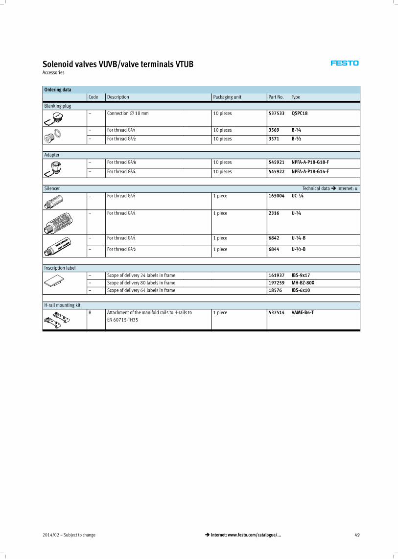
Ordering data
Code Description Packaging unit Part No. Type
Blanking plug
– Connection∅ 18 mm 10 pieces 537533 QSPC18
– For thread G¼ 10 pieces 3569 B-¼
– For thread G½ 10 pieces 3571 B-½
Adapter
– For thread GÁ 10 pieces 545921 NPFA-A-P18-G18-F
– For thread G¼ 10 pieces 545922 NPFA-A-P18-G14-F
Silencer Technical data� Internet: u
– For thread G¼ 1 piece 165004 UC-¼
– For thread G¼ 1 piece 2316 U-¼
– For thread G¼ 1 piece 6842 U-¼-B
– For thread G½ 1 piece 6844 U-½-B
Inscription label
– Scope of delivery 24 labels in frame 161937 IBS-9x17
– Scope of delivery 80 labels in frame 197259 MH-BZ-80X
– Scope of delivery 64 labels in frame 18576 IBS-6x10
H-rail mounting kit
H Attachment of the manifold rails to H-rails to
EN 60715-TH35
1 piece 537514 VAME-B6-T
Subject to change – 2014/0250 � Internet: www.festo.com/catalogue/...
Solenoid valves VUVB/valve terminals VTUBAccessories
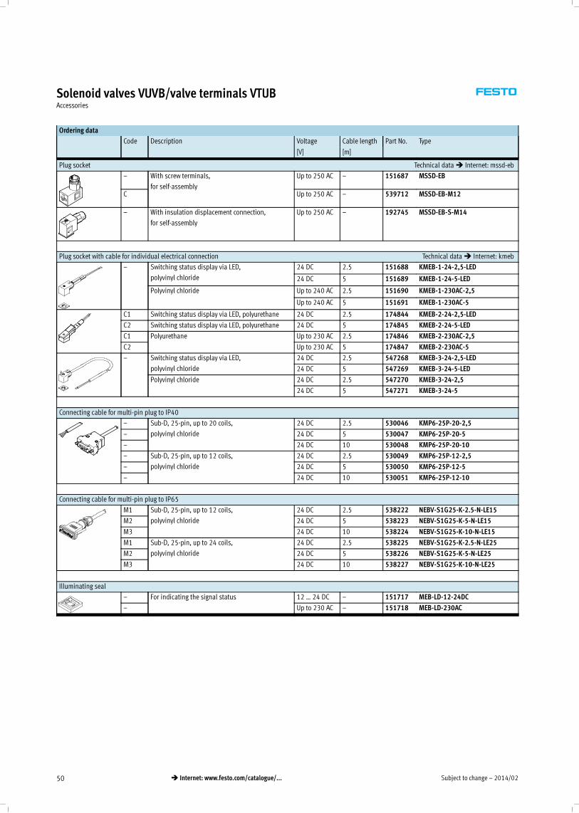
Ordering data
Code Description Voltage Cable length Part No. Type
[V] [m]
Plug socket Technical data� Internet: mssd-eb
– With screw terminals,
for self-assembly
Up to 250 AC – 151687 MSSD-EB
C Up to 250 AC – 539712 MSSD-EB-M12
– With insulation displacement connection,
for self-assembly
Up to 250 AC – 192745 MSSD-EB-S-M14
Plug socket with cable for individual electrical connection Technical data� Internet: kmeb
– Switching status display via LED,
polyvinyl chloride
24 DC 2.5 151688 KMEB-1-24-2,5-LED
24 DC 5 151689 KMEB-1-24-5-LED
Polyvinyl chloride Up to 240 AC 2.5 151690 KMEB-1-230AC-2,5
Up to 240 AC 5 151691 KMEB-1-230AC-5
C1 Switching status display via LED, polyurethane 24 DC 2.5 174844 KMEB-2-24-2,5-LED
C2 Switching status display via LED, polyurethane 24 DC 5 174845 KMEB-2-24-5-LED
C1 Polyurethane Up to 230 AC 2.5 174846 KMEB-2-230AC-2,5
C2 Up to 230 AC 5 174847 KMEB-2-230AC-5
– Switching status display via LED,
polyvinyl chloride
24 DC 2.5 547268 KMEB-3-24-2,5-LED
24 DC 5 547269 KMEB-3-24-5-LED
Polyvinyl chloride 24 DC 2.5 547270 KMEB-3-24-2,5
24 DC 5 547271 KMEB-3-24-5
Connecting cable for multi-pin plug to IP40
– Sub-D, 25-pin, up to 20 coils,
polyvinyl chloride
24 DC 2.5 530046 KMP6-25P-20-2,5
– 24 DC 5 530047 KMP6-25P-20-5
– 24 DC 10 530048 KMP6-25P-20-10
– Sub-D, 25-pin, up to 12 coils,
polyvinyl chloride
24 DC 2.5 530049 KMP6-25P-12-2,5
– 24 DC 5 530050 KMP6-25P-12-5
– 24 DC 10 530051 KMP6-25P-12-10
Connecting cable for multi-pin plug to IP65
M1 Sub-D, 25-pin, up to 12 coils,
polyvinyl chloride
24 DC 2.5 538222 NEBV-S1G25-K-2.5-N-LE15
M2 24 DC 5 538223 NEBV-S1G25-K-5-N-LE15
M3 24 DC 10 538224 NEBV-S1G25-K-10-N-LE15
M1 Sub-D, 25-pin, up to 24 coils,
polyvinyl chloride
24 DC 2.5 538225 NEBV-S1G25-K-2.5-N-LE25
M2 24 DC 5 538226 NEBV-S1G25-K-5-N-LE25
M3 24 DC 10 538227 NEBV-S1G25-K-10-N-LE25
Illuminating seal
– For indicating the signal status 12 … 24 DC – 151717 MEB-LD-12-24DC
– Up to 230 AC – 151718 MEB-LD-230AC