Embed Size (px)
Citation preview
Installation Manual
MA551601
354 / 355 Combination Lighting System
MA
7063
03
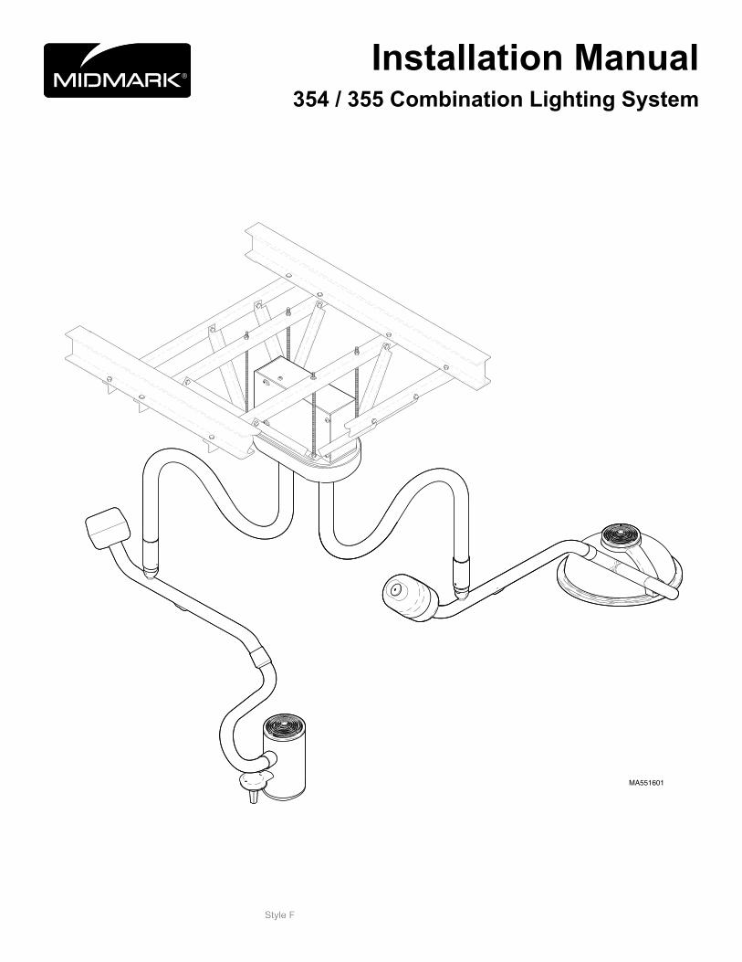
Hei
ght o
f Lig
hthe
ad A
ssem
bly
Adj
usta
ble
from
53.
0 in
. (13
5.0
cm)
to 7
8.0
in. (
198.
1 cm
) ab
ove
floor
.
Bas
ed o
n 8'
uni
ts w
ith 8
' Cei
ling
a
nd 9
' uni
ts w
ith 9
' Cei
ling
Hei
ght o
f Lig
hthe
ad A
ssem
bly
Adj
usta
ble
from
50.
0 in
. (12
7.0
cm)
to 7
4.0
in. (
188
cm)
abov
e flo
or
Bas
ed o
n 8'
uni
ts w
ith 8
' Cei
ling
a
nd 9
' uni
ts w
ith 9
' Cei
ling
540˚ 35
˚
180˚
580˚
580˚
580˚
580˚
540˚
35˚ 35
˚
180˚
29.5
in.
(70.
6 cm
)
13.3
in.
(33.
8 cm
)
50.7
5 in
.(1
24.5
cm
)49
.5 in
.(1
25.7
cm
)
13.3
in.
(33.
8 cm
)
27.5
in.
(69.
8 cm
)
58.2
in.
(147
.8 c
m)
53.7
5 in
.(1
32.0
cm
)
35˚
16 in
.(4
0.6
cm)
3.4
in.
(8.6
cm
)
11.4
in.
(28.
9 cm
)
With
8' D
own
tube
:
With
9' D
own
Tub
e
Important! - Please Read FirstThis document is broken down into three parts: This page, which provides additional information for installing a 354 / 355 combination light, a 354 Installation Manual, and a 355 Installation Manual.
Additional information required to install a 354 /355 combination light.
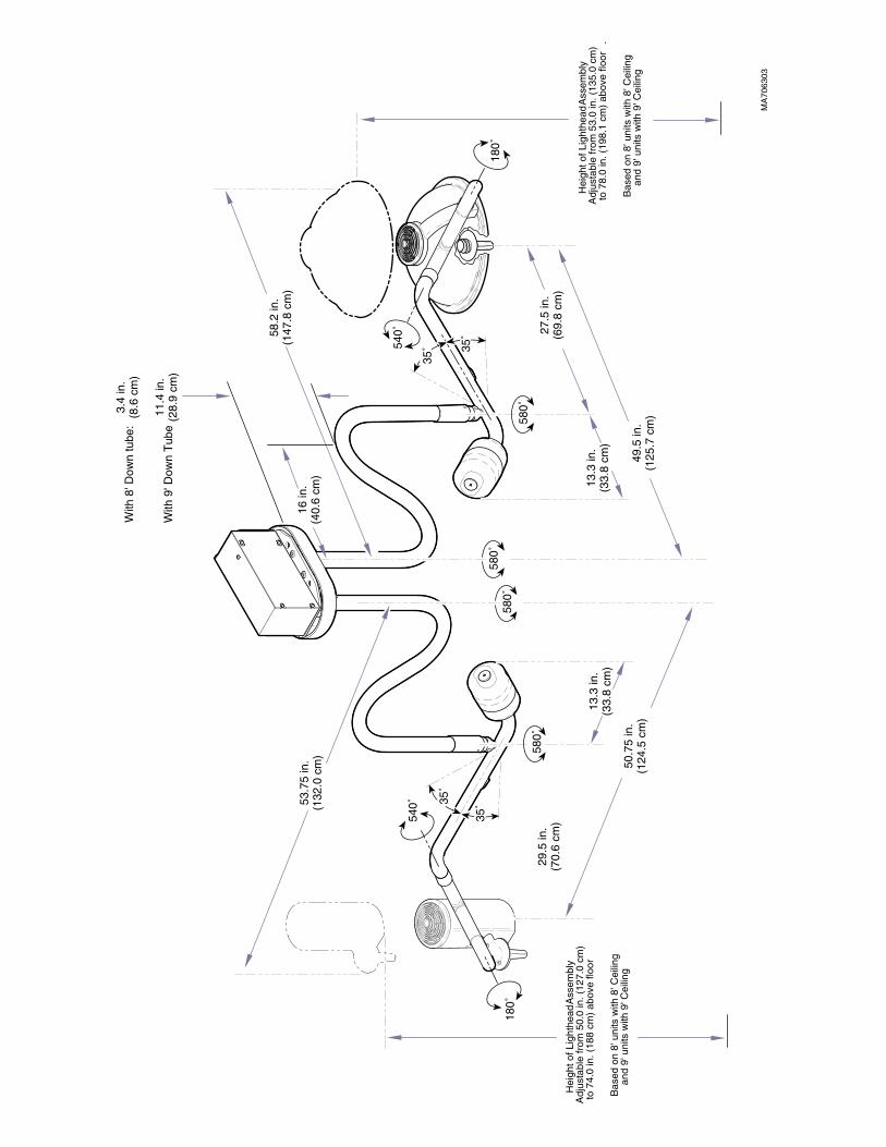
Equipment AlertFailure to connect the correct model to the correct transformer may result in a blown fuse and / or bulb.
The 354 light system’s down arm and 355 light system’s down arm must be connected to the ceiling plate in the posi-tion shown (see Figure A). This is necessary because the transformer output voltage is different for each light system and is not interchangeable. To identify the correct mounting location for each light, inspect the transformers. The model 354 transformer is labeled with part number 015-1206-00 and its secondary leads are marked as S-1 (blue wire) and S-2 (brown wire). The model 355 transformer is labeled with part number 015-1356-00 and its secondary leads are un-marked.
Use the following two pages of additional information plus the instructions contained in the 354 Installation manual to install and adjust the 354 Lighting System. Use the following two pages of additional information plus the instructions contained in the 355 Installation manual to install and adjust the 355 Lighting System
MA551700
S1
S2
Figure A. Mounting Locations for the for the 354 and 355 Downarms on a 354 / 355 Combination Lighting System
354 DownARM
wIRES noT TAGGED
355 DownARM
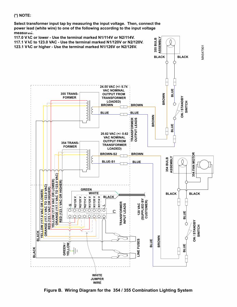
(*) noTE:
Select transformer input tap by measuring the input voltage. Then, connect the power lead (white wire) to one of the following according to the input voltage measured: 117.0 VAC or lower - Use the terminal marked n1/114V or n2/114V. 117.1 VAC to 123.0 VAC - Use the terminal marked n1/120V or n2/120V. 123.1 VAC or higher - Use the terminal marked n1/126V or n2/126V.
MA
5479
01
Figure B. wiring Diagram for the 354 / 355 Combination Lighting System
BLA
Ck
BLA
Ck
YELL
ow
(117
.0 V
AC
oR
Lo
wER
)o
RA
nG
E (1
17.1
VA
C T
o 1
23.0
VA
C)
RED
(123
.1 V
AC
oR
HIG
HER
)YE
LLo
w (1
17.0
VA
C o
R L
ow
ER)
RED
(123
.1 V
AC
oR
HIG
HER
)o
RA
nG
E (1
17.1
VA
C T
o 1
23.0
VA
C)
354 TRAnS- FoRMER
355 TRAnS- FoRMER
24.55 VAC (+/- 0.74 VAC noMInAL oUTPUT FRoM TRAnSFoRMER
LoADED)
20.82 VAC (+/- 0.62 VAC noMInAL oUTPUT FRoM TRAnSFoRMER
LoADED)
BRown
BRown-S2
BLUE
BRown
BLUE
BLUE-S1
BRown
BLUE
GREEnwHITE
BLACk
G n2/
126
V
n2/
120
V
n2/
114
V
n1/
126
Vn
1/12
0 V
n1/
114
V
L
(*)
TRA
nSF
oR
MER
o
UTP
UT
LEA
DS
120
VAC
(S
UPP
LIED
BY
C
UST
oM
ER)
BR
ow
n
BR
ow
nB
Ro
wn
TRA
nSF
oR
MER
In
PUT
LEA
DS
BLU
E
BLU
E35
4 B
ULB
ASS
EMB
LY
GR
EEn
/ YE
LLo
w
LIn
E FU
SES
BLU
EBLU
E
BLU
E
BLACkBLACk
BLACkBLACk35
4 FA
n M
oTo
R
355
BU
LBA
SSEM
BLY
on
/ ST
An
DB
YSw
ITC
H
on
/ ST
An
DB
YSw
ITC
H
wHITE jUMPER
wIRE
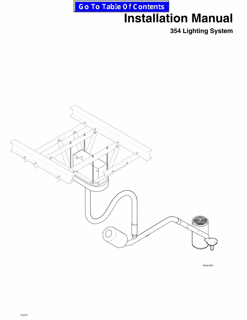
Installation Manual354 Lighting System
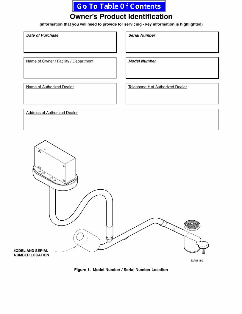
Owner’s Product Identification(information that you will need to provide for servicing - key information is highlighted)
Date of Purchase Serial Number
Name of Owner / Facility / Department Model Number
Name of Authorized Dealer Telephone # of Authorized Dealer
Address of Authorized Dealer
Figure 1. Model Number / Serial Number Location
MA551801
MODEL AND SERIAL NUMBER LOCATION

CONTENTS
IMPORTANT INFORMATION.................................................................................................2Scope and Purpose of this Manual................................................................................2Intended Use of Product ................................................................................................2Safety Instructions .........................................................................................................2Explanation of Safety Symbols and Notes.....................................................................2Transportation and Storage Conditions .........................................................................3
GENERAL INFORMATION ....................................................................................................3Lighting System .............................................................................................................3Specifications.................................................................................................................3
354 LIGHTING SYSTEM INSTALLATION.............................................................................4Unpacking......................................................................................................................4Recommended Ceiling Mounting Locations (For Dental and Medical Applications) .........................................................................5Ceiling Support Structure Installation ............................................................................5Electromagnetic Interference.........................................................................................6Wiring Installation ..........................................................................................................7Junction Box Wiring Connections ..................................................................................7Ceiling Plate Assembly Installation................................................................................9Down Tube Installation.................................................................................................11Cross Tube Assembly Installation................................................................................12Housing Cap Installation..............................................................................................13Operational Test...........................................................................................................13
TROUBLESHOOTING..........................................................................................................13Troubleshooting Guide.................................................................................................13
ADJUSTMENTS ...................................................................................................................16Ball Pivot Tension Adjustment......................................................................................16Cross Tube Counterbalance Adjustment .....................................................................16
CALLING FOR SERVICE.....................................................................................................17LIMITED WARRANTY ..........................................................................................................18

© Midmark Corporation 1998 Page 2 Printed in U.S.A.
IMPORTANT INFORMATION
SCOPE AND PURPOSE OF THIS MANUAL
This manual covers complete instructions for the instal-lation of the 354 Lighting System and is intended to be used by personnel involved in the installation of the 354 Lighting System. The Operation Manual (Part Number: 003-1071-xx) for the 354 Lighting System is a separate document and is intended for persons who will operate the 354 Lighting System.
INTENDED USE OF PRODUCT
This product is intended for use in all medical environ-ments where illumination is required for external exami-nations and procedures.
SAFETY INSTRUCTIONS
The primary concern of Midmark is that this equipment be operated and maintained with the safety of the users in mind. To assure safer and more reliable operation, do the following: (1) Read this manual before installing your light assembly; (2) Assure that appropriate per-sonnel are informed on the contents of this manual--this is the responsibility of the purchaser; (3) Be sure that you understand the instructions contained in this man-ual before attempting to install this light assembly; (4) Be sure that you have read and understand the instruc-tions contained in the Operation Manual (a separate document) before attempting to operate this equipment.
EXPLANATION OF SAFETY SYMBOLS AND NOTES
Throughout this manual are safety alert symbols that call attention to particular procedures. These items are
used as follows:
DANGERA DANGER is used for an imminently hazardous operating procedure, prac-
tice, or condition which, if not correctly followed, will result in loss of life or serious personal injury.
WARNINGA WARNING is used for a potentially hazardous operating procedure, prac-
tice, or condition which, if not correctly followed, could result in loss of life or serious personal injury.
CAUTIONA CAUTION is used for a potentially haz-ardous operating procedure, practice, or
condition which, if not correctly followed, could result in minor or moderate injury. It may also be used to alert against unsafe practices.
EQUIPMENT ALERTAn EQUIPMENT ALERT is used for an imminently or potentially hazardous oper-
ating procedure, practice, or condition which, if not correctly followed, will or could result in serious, mod-erate, or minor damage to unit.
NOTEA NOTE is used to amplify an operating procedure, practice or condition.
Indicates that the unit is rated: Type B, Applied Part.
Indicates that the operator’s manual should be con-sulted for important information.
Indicates the presence of a dangerous voltage / shock hazard.
Indicates a fuse rating specification
Indicates a protective earth ground.
Indicates that the product is fragile; do not handle roughly.
Indicates the proper shipping orientation for the prod-uct.
Indicates that the product must be kept dry.
Indicates a hot surface.
© Midmark Corporation 1998 Page 3 Printed in U.S.A.
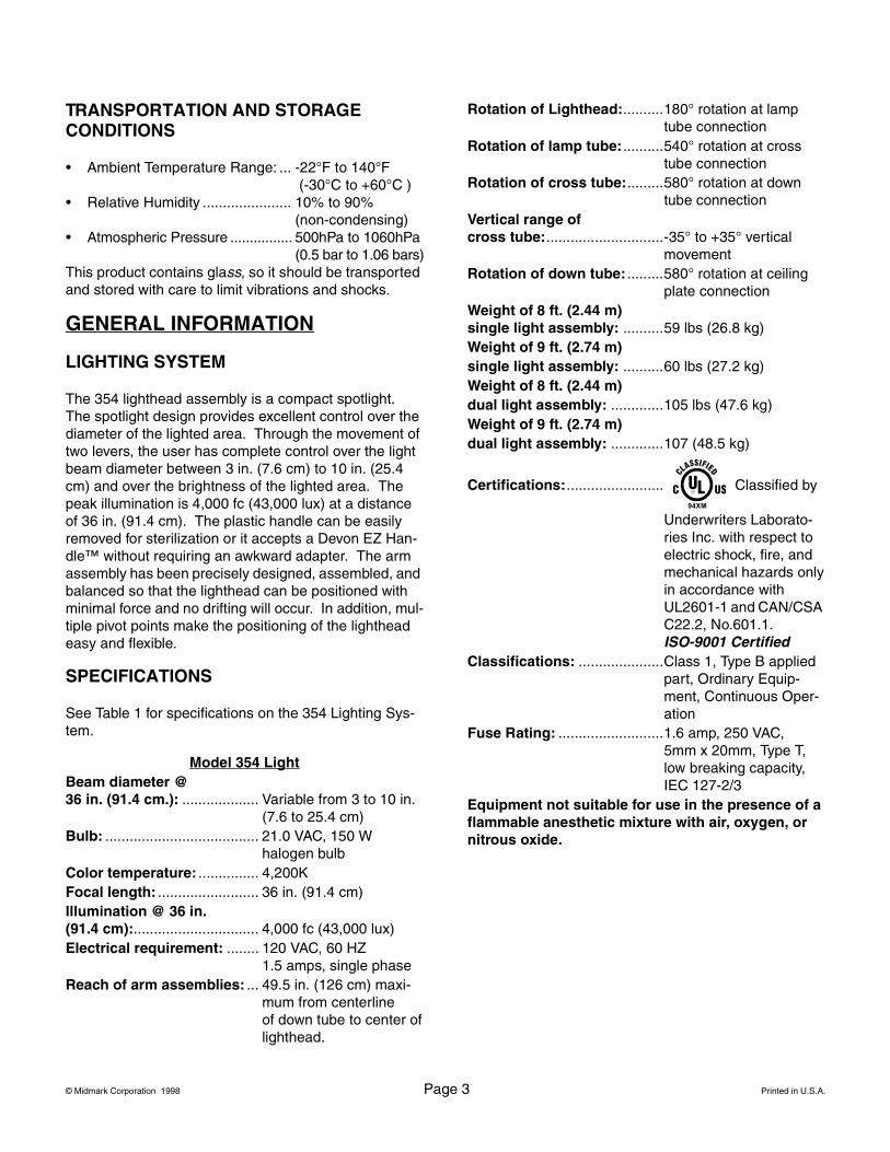
TRANSPORTATION AND STORAGE CONDITIONS
• Ambient Temperature Range: ... -22°F to 140°F (-30°C to +60°C )
• Relative Humidity ...................... 10% to 90%(non-condensing)
• Atmospheric Pressure ................ 500hPa to 1060hPa(0.5 bar to 1.06 bars)
This product contains glass, so it should be transported and stored with care to limit vibrations and shocks.
GENERAL INFORMATION
LIGHTING SYSTEM
The 354 lighthead assembly is a compact spotlight. The spotlight design provides excellent control over the diameter of the lighted area. Through the movement of two levers, the user has complete control over the light beam diameter between 3 in. (7.6 cm) to 10 in. (25.4 cm) and over the brightness of the lighted area. The peak illumination is 4,000 fc (43,000 lux) at a distance of 36 in. (91.4 cm). The plastic handle can be easily removed for sterilization or it accepts a Devon EZ Han-dle™ without requiring an awkward adapter. The arm assembly has been precisely designed, assembled, and balanced so that the lighthead can be positioned with minimal force and no drifting will occur. In addition, mul-tiple pivot points make the positioning of the lighthead easy and flexible.
SPECIFICATIONS
See Table 1 for specifications on the 354 Lighting Sys-tem.
Model 354 LightBeam diameter @ 36 in. (91.4 cm.): ................... Variable from 3 to 10 in.
(7.6 to 25.4 cm)Bulb: ...................................... 21.0 VAC, 150 W
halogen bulbColor temperature: ............... 4,200KFocal length: ......................... 36 in. (91.4 cm)Illumination @ 36 in.(91.4 cm):............................... 4,000 fc (43,000 lux)Electrical requirement: ........ 120 VAC, 60 HZ
1.5 amps, single phaseReach of arm assemblies: ... 49.5 in. (126 cm) maxi-
mum from centerline of down tube to center oflighthead.
Rotation of Lighthead:..........180° rotation at lamptube connection
Rotation of lamp tube: ..........540° rotation at crosstube connection
Rotation of cross tube:.........580° rotation at downtube connection
Vertical range of cross tube:.............................-35° to +35° vertical
movementRotation of down tube: .........580° rotation at ceiling
plate connectionWeight of 8 ft. (2.44 m) single light assembly: ..........59 lbs (26.8 kg)Weight of 9 ft. (2.74 m) single light assembly: ..........60 lbs (27.2 kg)Weight of 8 ft. (2.44 m) dual light assembly: .............105 lbs (47.6 kg)Weight of 9 ft. (2.74 m) dual light assembly: .............107 (48.5 kg)
Certifications:........................ Classified by
Underwriters Laborato-ries Inc. with respect to electric shock, fire, and mechanical hazards onlyin accordance withUL2601-1 and CAN/CSA C22.2, No.601.1.ISO-9001 Certified
Classifications: .....................Class 1, Type B applied part, Ordinary Equip-ment, Continuous Oper-ation
Fuse Rating: ..........................1.6 amp, 250 VAC, 5mm x 20mm, Type T,low breaking capacity,IEC 127-2/3
Equipment not suitable for use in the presence of a flammable anesthetic mixture with air, oxygen, or nitrous oxide.
94XM
© Midmark Corporation 1998 Page 4 Printed in U.S.A.
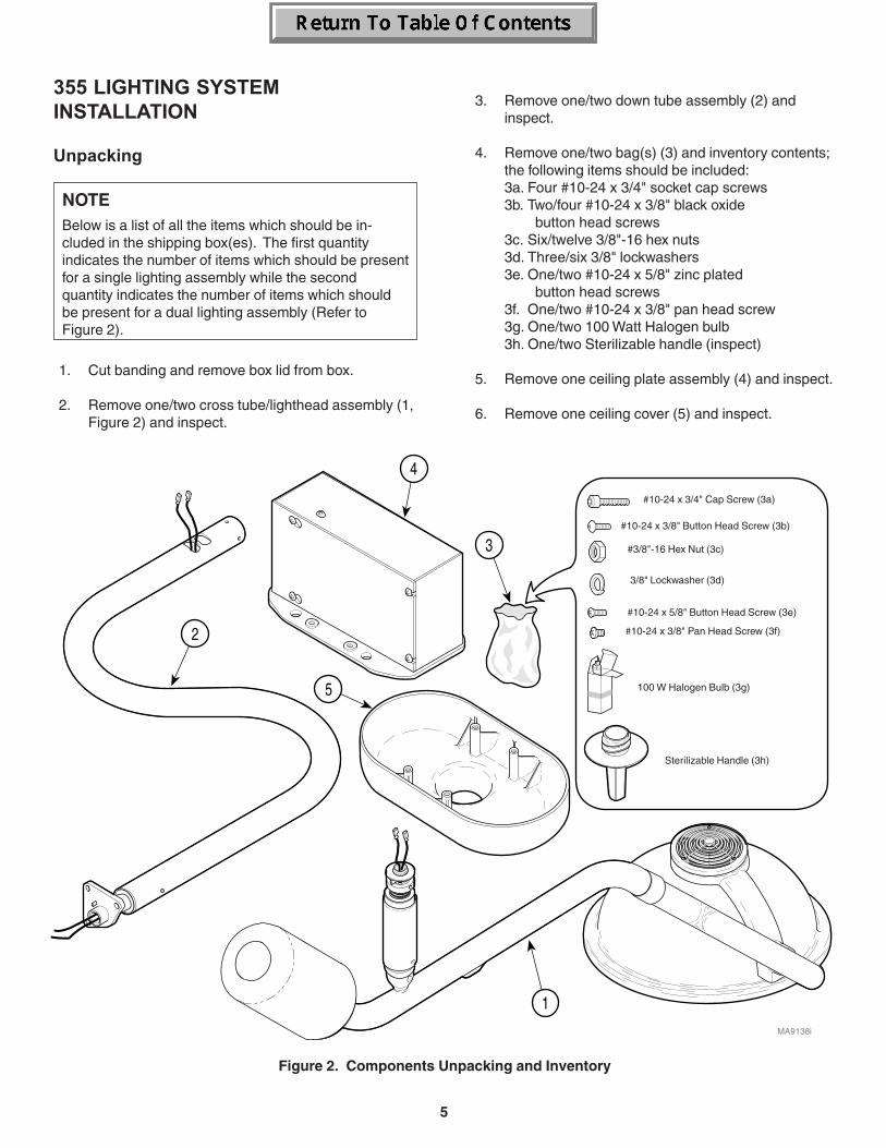
354 LIGHTING SYSTEM INSTALLATION
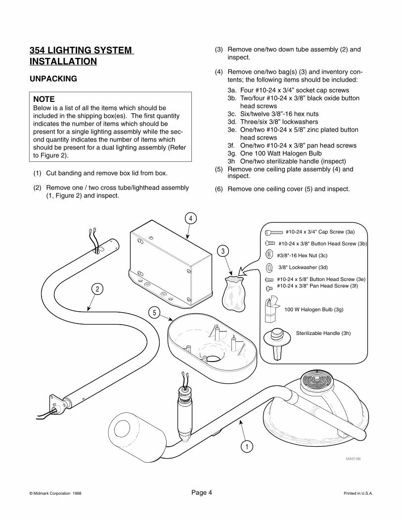
UNPACKING
(1) Cut banding and remove box lid from box.
(2) Remove one / two cross tube/lighthead assembly (1, Figure 2) and inspect.
(3) Remove one/two down tube assembly (2) and inspect.
(4) Remove one/two bag(s) (3) and inventory con-tents; the following items should be included:
3a. Four #10-24 x 3/4” socket cap screws3b. Two/four #10-24 x 3/8” black oxide button
head screws3c. Six/twelve 3/8”-16 hex nuts3d. Three/six 3/8” lockwashers3e. One/two #10-24 x 5/8” zinc plated button
head screws3f. One/two #10-24 x 3/8” pan head screws3g. One 100 Watt Halogen Bulb3h One/two sterilizable handle (inspect)
(5) Remove one ceiling plate assembly (4) and inspect.
(6) Remove one ceiling cover (5) and inspect.
NOTEBelow is a list of all the items which should be included in the shipping box(es). The first quantity indicates the number of items which should be present for a single lighting assembly while the sec-ond quantity indicates the number of items which should be present for a dual lighting assembly (Refer to Figure 2).
2
1
4
3
MA9138i
5
#10-24 x 3/4" Cap Screw (3a)
#10-24 x 3/8" Button Head Screw (3b)
#3/8"-16 Hex Nut (3c)
3/8" Lockwasher (3d)
#10-24 x 5/8" Button Head Screw (3e) #10-24 x 3/8" Pan Head Screw (3f)
100 W Halogen Bulb (3g)
Sterilizable Handle (3h)
© Midmark Corporation 1998 Page 5 Printed in U.S.A.
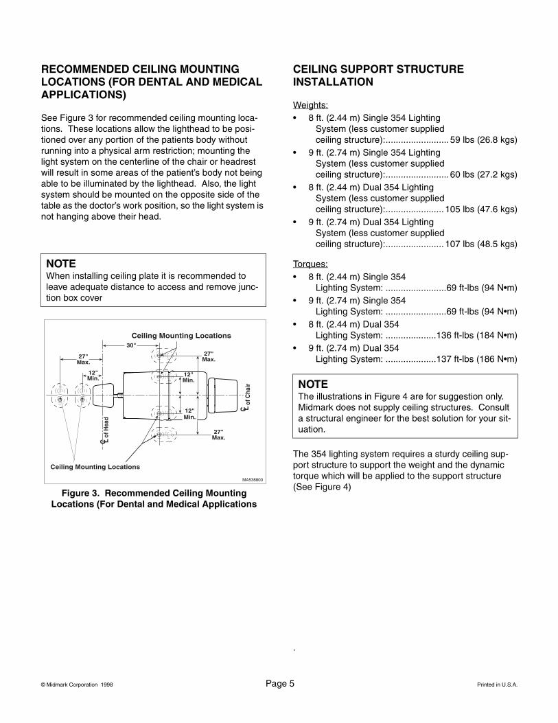
RECOMMENDED CEILING MOUNTING LOCATIONS (FOR DENTAL AND MEDICAL APPLICATIONS)
See Figure 3 for recommended ceiling mounting loca-tions. These locations allow the lighthead to be posi-tioned over any portion of the patients body without running into a physical arm restriction; mounting the light system on the centerline of the chair or headrest will result in some areas of the patient’s body not being able to be illuminated by the lighthead. Also, the light system should be mounted on the opposite side of the table as the doctor’s work position, so the light system is not hanging above their head.
CEILING SUPPORT STRUCTURE INSTALLATION
Weights:• 8 ft. (2.44 m) Single 354 Lighting
System (less customer supplied ceiling structure):......................... 59 lbs (26.8 kgs)
• 9 ft. (2.74 m) Single 354 Lighting System (less customer supplied ceiling structure):......................... 60 lbs (27.2 kgs)
• 8 ft. (2.44 m) Dual 354 Lighting System (less customer supplied ceiling structure):....................... 105 lbs (47.6 kgs)
• 9 ft. (2.74 m) Dual 354 Lighting System (less customer supplied ceiling structure):....................... 107 lbs (48.5 kgs)
Torques:• 8 ft. (2.44 m) Single 354
Lighting System: ........................69 ft-lbs (94 N•m)• 9 ft. (2.74 m) Single 354
Lighting System: ........................69 ft-lbs (94 N•m)• 8 ft. (2.44 m) Dual 354
Lighting System: ....................136 ft-lbs (184 N•m)• 9 ft. (2.74 m) Dual 354
Lighting System: ....................137 ft-lbs (186 N•m)
The 354 lighting system requires a sturdy ceiling sup-port structure to support the weight and the dynamic torque which will be applied to the support structure (See Figure 4)
.
NOTEWhen installing ceiling plate it is recommended to leave adequate distance to access and remove junc-tion box cover
Ceiling Mounting Locations
Ceiling Mounting Locations
30"
of C
hair
C L
of H
ead
C L
27"Max.
12"Min.
27"Max.
12"Min.
12"Min.
27"Max.
MA538800
Figure 3. Recommended Ceiling Mounting Locations (For Dental and Medical Applications
NOTEThe illustrations in Figure 4 are for suggestion only. Midmark does not supply ceiling structures. Consult a structural engineer for the best solution for your sit-uation.
© Midmark Corporation 1998 Page 6 Printed in U.S.A.
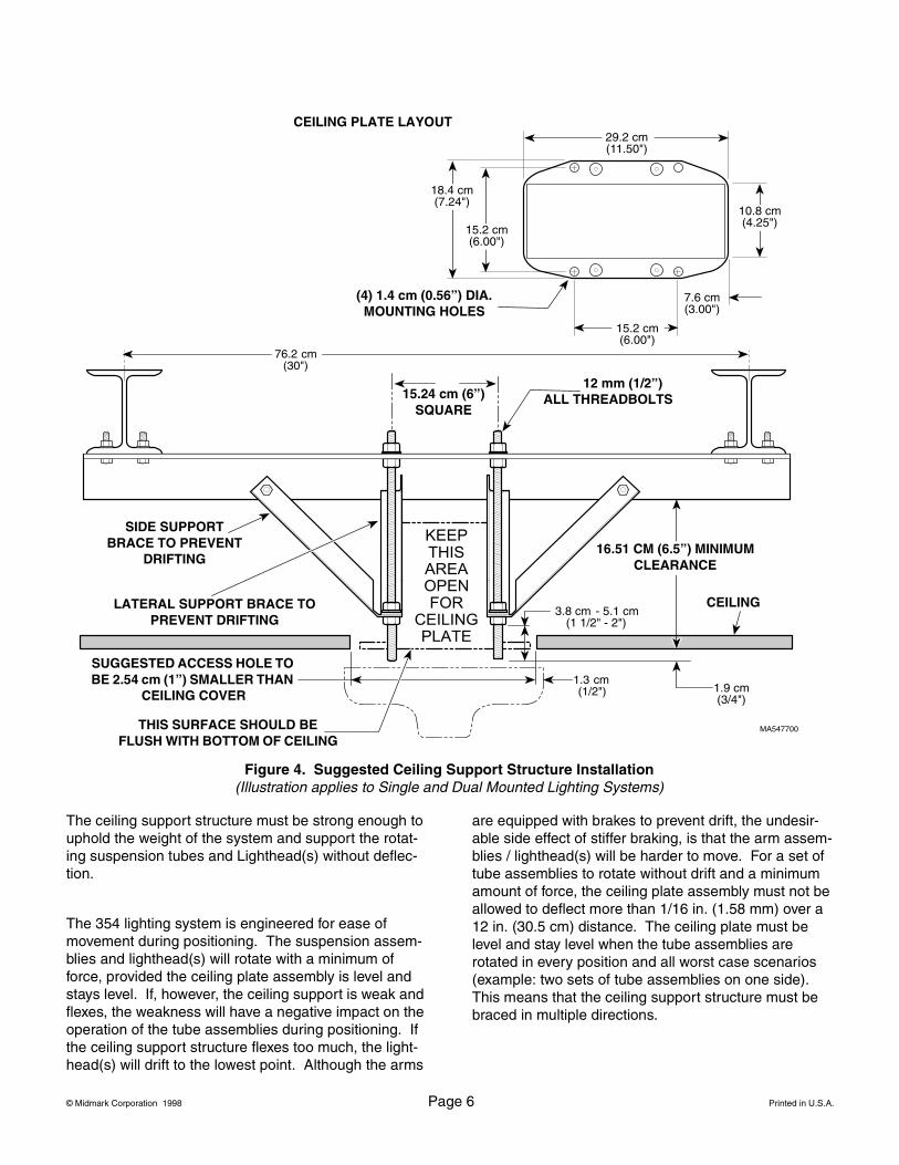
The ceiling support structure must be strong enough to uphold the weight of the system and support the rotat-ing suspension tubes and Lighthead(s) without deflec-tion.
The 354 lighting system is engineered for ease ofmovement during positioning. The suspension assem-blies and lighthead(s) will rotate with a minimum of force, provided the ceiling plate assembly is level and stays level. If, however, the ceiling support is weak and flexes, the weakness will have a negative impact on the operation of the tube assemblies during positioning. If the ceiling support structure flexes too much, the light-head(s) will drift to the lowest point. Although the arms
are equipped with brakes to prevent drift, the undesir-able side effect of stiffer braking, is that the arm assem-blies / lighthead(s) will be harder to move. For a set of tube assemblies to rotate without drift and a minimum amount of force, the ceiling plate assembly must not be allowed to deflect more than 1/16 in. (1.58 mm) over a 12 in. (30.5 cm) distance. The ceiling plate must be level and stay level when the tube assemblies are rotated in every position and all worst case scenarios (example: two sets of tube assemblies on one side). This means that the ceiling support structure must be braced in multiple directions.
MA547700
76.2 cm(30")
3.8 cm - 5.1 cm(1 1/2" - 2")
1.9 cm(3/4")
18.4 cm(7.24")
15.2 cm(6.00")
29.2 cm(11.50")
10.8 cm(4.25")
7.6 cm(3.00")
15.2 cm(6.00")
1.3 cm(1/2")
Figure 4. Suggested Ceiling Support Structure Installation(Illustration applies to Single and Dual Mounted Lighting Systems)
(4) 1.4 cm (0.56”) DIA.MOUNTING HOLES
CEILING PLATE LAYOUT
15.24 cm (6”)SQUARE
12 mm (1/2”)ALL THREADBOLTS
SIDE SUPPORT BRACE TO PREVENT
DRIFTING
LATERAL SUPPORT BRACE TO PREVENT DRIFTING
16.51 CM (6.5”) MINIMUM CLEARANCE
SUGGESTED ACCESS HOLE TO BE 2.54 cm (1”) SMALLER THAN
CEILING COVER
THIS SURFACE SHOULD BE FLUSH WITH BOTTOM OF CEILING
CEILING
© Midmark Corporation 1998 Page 7 Printed in U.S.A.
The 354 lighting system comes in two different versions: an 8 ft. (2.44 m) version for a 8 ft. (2.44 m) ceiling and a 9 ft. (2.74 m) version for a 9 ft. (2.74 m) ceiling. The bottom of the ceiling plate assembly must be installed so it is flush with the finished surface of the facility’s ceil-ing. See Figure 4. The ceiling cover is designed to fit up against the finished ceiling.
ELECTROMAGNETIC INTERFERENCE
This product is designed and built to minimize electro-magnetic interference with other devices. However, if interference is noticed between another device and this product, remove the interfering device from the room or wire this product into an isolated circuit.
WIRING INSTALLATION
The wiring, supplying power to the junction box of the 354 lighting system, must be supplied by the customer. The 354 lighting system requires 120 VAC input voltage. The wire should be a 2-conductor with ground, 14 gauge copper wiring, rated for 120 VAC. The customer supplied wiring must be connected to the junction box with some form of strain relief fitting, preferably a con-duit fitting. Connect and route the wiring in accordance with local and national codes, using conduit where nec-essary. See wiring diagram, Figure 5.
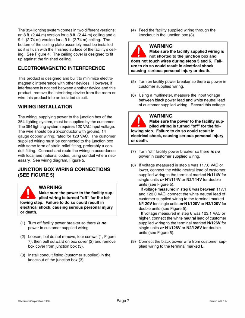
JUNCTION BOX WIRING CONNECTIONS (SEE FIGURE 5)
(1) Turn off facility power breaker so there is no power in customer supplied wiring.
(2) Loosen, but do not remove, four screws (1, Figure 7); then pull outward on box cover (2) and remove box cover from junction box (3).
(3) Install conduit fitting (customer supplied) in the knockout of the junction box (3).
(4) Feed the facility supplied wiring through the knockout in the junction box (3).
(5) Turn on facility power breaker so there is power in customer supplied wiring.
(6) Using a multimeter, measure the input voltage between black power lead and white neutral lead of customer supplied wiring. Record this voltage.
(7) Turn “off” facility power breaker so there is no power in customer supplied wiring.
(8) If voltage measured in step 6 was 117.0 VAC or lower, connect the white neutral lead of customer supplied wiring to the terminal marked N/114V for single units or N1/114V or N2/114V for double units (see Figure 5). If voltage measured in step 6 was between 117.1 and 123.0 VAC, connect the white neutral lead of customer supplied wiring to the terminal marked N/120V for single units or N1/120V or N2/120V for double units (see Figure 5). If voltage measured in step 6 was 123.1 VAC or higher, connect the white neutral lead of customer supplied wiring to the terminal marked N/126V for single units or N1/126V or N2/126V for double units (see Figure 5).
(9) Connect the black power wire from customer sup-plied wiring to the terminal marked L.
WARNINGMake sure the power to the facility sup-plied wiring is turned “off” for the fol-
lowing step. Failure to do so could result in electrical shock, causing serious personal injury or death.
WARNINGMake sure the facility supplied wiring is not shorted to the junction box and
does not touch wires during steps 5 and 6. Fail-ure to do so could result in electrical shock, causing serious personal injury or death.
WARNINGMake sure the power to the facility sup-plied wiring is turned “off” for the fol-
lowing step. Failure to do so could result in electrical shock, causing serious personal injury or death.
© Midmark Corporation 1998 Page 8 Printed in U.S.A.
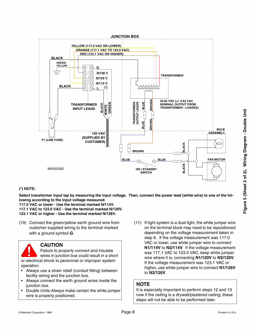
(10) Connect the green/yellow earth ground wire from customer supplied wiring to the terminal marked with a ground symbol G.
(11) If light system is a dual light, the white jumper wire on the terminal block may need to be repositioned depending on the voltage measurement taken in step 6. If the voltage measurement was 117.0 VAC or lower, use white jumper wire to connect N1/114V to N2/114V. If the voltage measurement was 117.1 VAC to 123.0 VAC, keep white jumper wire where it is; connecting N1/120V to N2/120V. If the voltage measurement was 123.1 VAC or higher, use white jumper wire to connect N1/126V to N2/126V.
(*) NOTE:
Select transformer input tap by measuring the input voltage. Then, connect the power lead (white wire) to one of the fol-lowing according to the input voltage measured:117.0 VAC or lower - Use the terminal marked N/114V.117.1 VAC to 123.0 VAC - Use the terminal marked N/120V.123.1 VAC or higher - Use the terminal marked N/126V.
JUNCTION BOX
YELLOW (117.0 VAC OR LOWER)ORANGE (117.1 VAC TO 123.0 VAC)
RED (123.1 VAC OR HIGHER)
TRANSFORMER INPUT LEADS
WH
ITE
BLACK
GR
EE
N
N/114 V
TRANSFORMER
TR
AN
SF
OR
ME
RO
UT
PU
T L
EA
DS
ON / STANDBY SWITCH
BULBASSEMBLY
BL
AC
K
BLUE
BROWN
BL
UE
BR
OW
N
BL
AC
K
GREEN/YELLOW
F1 (LINE FUSE)
FAN MOTOR
20.82 VAC (+/- 0.62 VAC NOMINAL OUTPUT FROM TRANSFORMER - LOADED)
120 VAC(SUPPLIED BY
CUSTOMER)B
LU
E
BR
OW
N
BLUE
BLACK
G
L
N/120 V
N/126 V
(*)
BL
AC
K
CAUTIONFailure to properly connect and insulate wires in junction box could result in a short
or electrical shock to personnel or improper system operation.• Always use a strain relief (conduit fitting) between
facility wiring and the junction box.• Always connect the earth ground wires inside the
junction box.• Double Units-Always make certain the white jumper
wire is properly positioned.
NOTEIt is especially important to perform steps 12 and 13 now if the ceiling is a drywall/plastered ceiling; these steps will not be able to be performed later.
Fig
ure
5 (
Sh
eet
2 o
f 2)
. W
irin
g D
iag
ram
- D
ou
ble
Un
it
© Midmark Corporation 1998 Page 9 Printed in U.S.A.
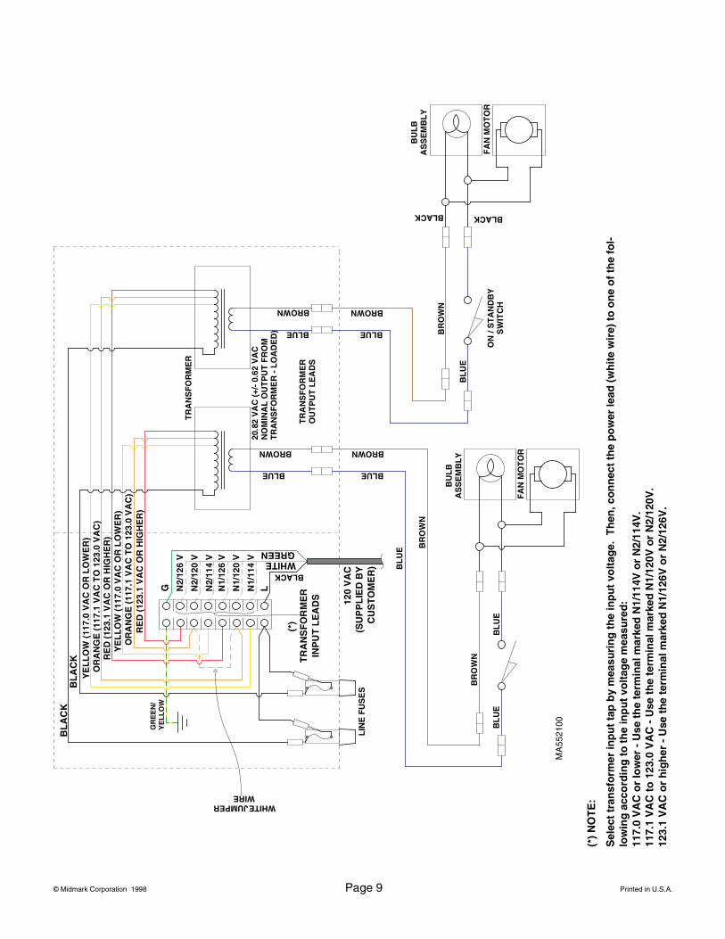
(*)
NO
TE
:
Sel
ect
tran
sfo
rmer
inp
ut
tap
by
mea
suri
ng
th
e in
pu
t vo
ltag
e. T
hen
, co
nn
ect
the
po
wer
lead
(w
hit
e w
ire)
to
on
e o
f th
e fo
l-lo
win
g a
cco
rdin
g t
o t
he
inp
ut
volt
age
mea
sure
d:
117.
0 V
AC
or
low
er -
Use
th
e te
rmin
al m
arke
d N
1/11
4V o
r N
2/11
4V.
117.
1 V
AC
to
123
.0 V
AC
- U
se t
he
term
inal
mar
ked
N1/
120V
or
N2/
120V
.12
3.1
VA
C o
r h
igh
er -
Use
th
e te
rmin
al m
arke
d N
1/12
6V o
r N
2/12
6V.
YE
LL
OW
(11
7.0
VA
C O
R L
OW
ER
)O
RA
NG
E (
117.
1 V
AC
TO
123
.0 V
AC
)R
ED
(12
3.1
VA
C O
R H
IGH
ER
)
TR
AN
SF
OR
ME
R
INP
UT
LE
AD
S
WHITE
BL
AC
K
GREEN
N2/
114
V
TR
AN
SF
OR
ME
R
TR
AN
SF
OR
ME
R
OU
TP
UT
LE
AD
S
ON
/ S
TA
ND
BY
S
WIT
CH
BU
LB
AS
SE
MB
LY
BLACK
BL
UE B
RO
WN
BLUE
BROWN
BLACK
GR
EE
N/
YE
LL
OW
LIN
E F
US
ES
FA
N M
OT
OR
20.8
2 V
AC
(+/
- 0.
62 V
AC
N
OM
INA
L O
UT
PU
T F
RO
M
TR
AN
SF
OR
ME
R -
LO
AD
ED
)
120
VA
C(S
UP
PL
IED
BY
CU
ST
OM
ER
)
BLUE
BROWN
BL
UE
BL
AC
K
G LN2/
120
V
N2/
126
V
(*)
BLACK
BLUE
BROWN
BR
OW
N
BLUE
BROWN
BU
LB
AS
SE
MB
LY
FA
N M
OT
OR
BL
UE
BL
UE
BR
OW
N
YE
LL
OW
(11
7.0
VA
C O
R L
OW
ER
)O
RA
NG
E (
117.
1 V
AC
TO
123
.0 V
AC
)R
ED
(12
3.1
VA
C O
R H
IGH
ER
)
N1/
114
V
N1/
120
V
N1/
126
V
WHITE JUMPER WIRE
© Midmark Corporation 1998 Page 10 Printed in U.S.A.
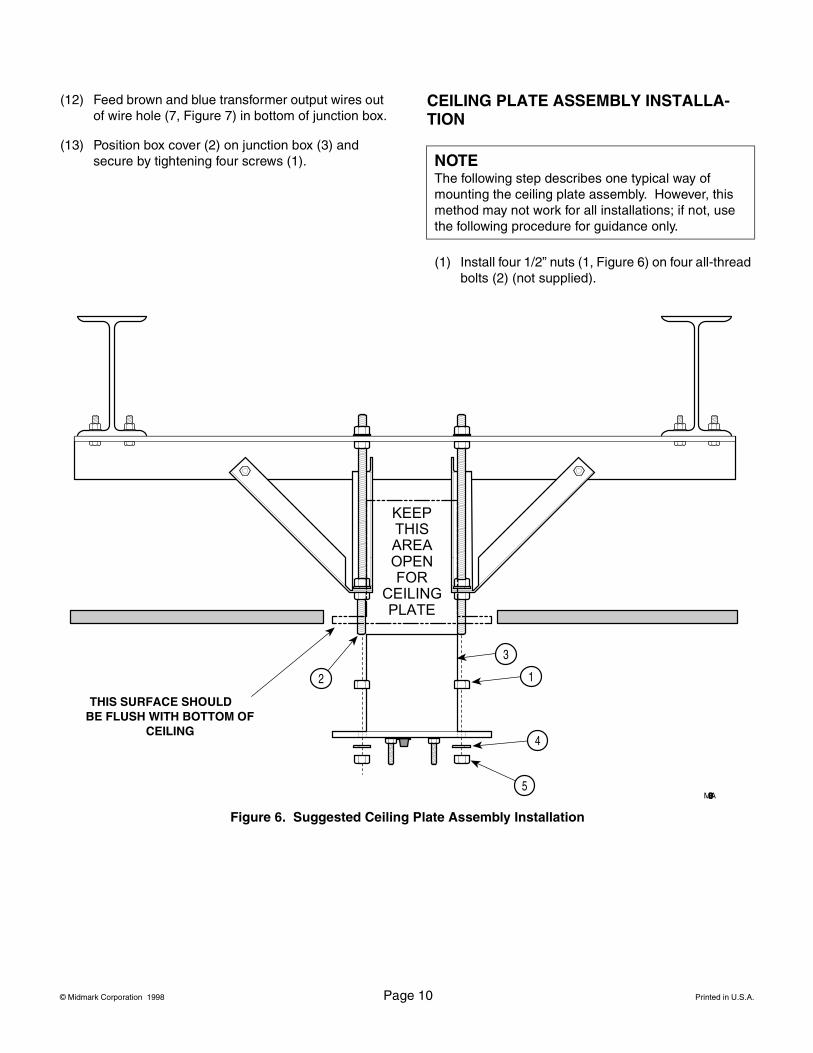
(12) Feed brown and blue transformer output wires out of wire hole (7, Figure 7) in bottom of junction box.
(13) Position box cover (2) on junction box (3) and secure by tightening four screws (1).
CEILING PLATE ASSEMBLY INSTALLA-TION
(1) Install four 1/2” nuts (1, Figure 6) on four all-thread bolts (2) (not supplied).
NOTEThe following step describes one typical way of mounting the ceiling plate assembly. However, this method may not work for all installations; if not, use the following procedure for guidance only.
5
1
3
2
4
MA32850
Figure 6. Suggested Ceiling Plate Assembly Installation
THIS SURFACE SHOULD BE FLUSH WITH BOTTOM OF
CEILING
© Midmark Corporation 1998 Page 11 Printed in U.S.A.
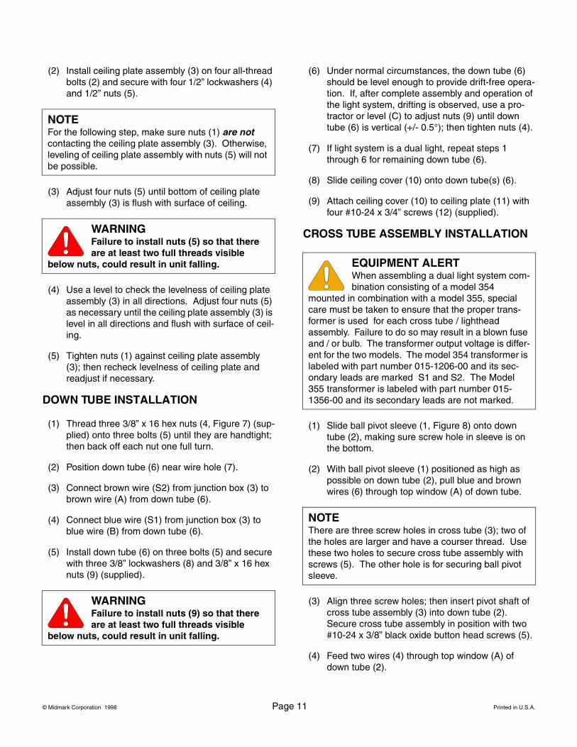
(2) Install ceiling plate assembly (3) on four all-thread bolts (2) and secure with four 1/2” lockwashers (4) and 1/2” nuts (5).
(3) Adjust four nuts (5) until bottom of ceiling plate assembly (3) is flush with surface of ceiling.
(4) Use a level to check the levelness of ceiling plate assembly (3) in all directions. Adjust four nuts (5) as necessary until the ceiling plate assembly (3) is level in all directions and flush with surface of ceil-ing.
(5) Tighten nuts (1) against ceiling plate assembly (3); then recheck levelness of ceiling plate and readjust if necessary.
DOWN TUBE INSTALLATION
(1) Thread three 3/8” x 16 hex nuts (4, Figure 7) (sup-plied) onto three bolts (5) until they are handtight; then back off each nut one full turn.
(2) Position down tube (6) near wire hole (7).
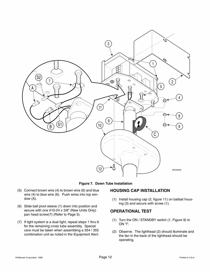
(3) Connect brown wire (S2) from junction box (3) to brown wire (A) from down tube (6).
(4) Connect blue wire (S1) from junction box (3) to blue wire (B) from down tube (6).
(5) Install down tube (6) on three bolts (5) and secure with three 3/8” lockwashers (8) and 3/8” x 16 hex nuts (9) (supplied).
(6) Under normal circumstances, the down tube (6) should be level enough to provide drift-free opera-tion. If, after complete assembly and operation of the light system, drifting is observed, use a pro-tractor or level (C) to adjust nuts (9) until down tube (6) is vertical (+/- 0.5°); then tighten nuts (4).
(7) If light system is a dual light, repeat steps 1 through 6 for remaining down tube (6).
(8) Slide ceiling cover (10) onto down tube(s) (6).
(9) Attach ceiling cover (10) to ceiling plate (11) with four #10-24 x 3/4” screws (12) (supplied).
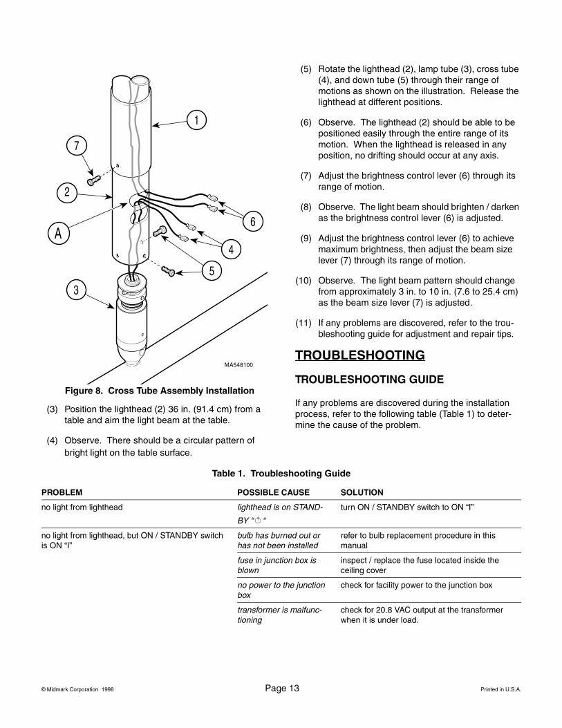
CROSS TUBE ASSEMBLY INSTALLATION
(1) Slide ball pivot sleeve (1, Figure 8) onto down tube (2), making sure screw hole in sleeve is on the bottom.
(2) With ball pivot sleeve (1) positioned as high as possible on down tube (2), pull blue and brown wires (6) through top window (A) of down tube.
(3) Align three screw holes; then insert pivot shaft of cross tube assembly (3) into down tube (2). Secure cross tube assembly in position with two #10-24 x 3/8” black oxide button head screws (5).
(4) Feed two wires (4) through top window (A) of down tube (2).
NOTEFor the following step, make sure nuts (1) are not contacting the ceiling plate assembly (3). Otherwise, leveling of ceiling plate assembly with nuts (5) will not be possible.
WARNINGFailure to install nuts (5) so that there are at least two full threads visible
below nuts, could result in unit falling.
WARNINGFailure to install nuts (9) so that there are at least two full threads visible
below nuts, could result in unit falling.
EQUIPMENT ALERTWhen assembling a dual light system com-bination consisting of a model 354
mounted in combination with a model 355, special care must be taken to ensure that the proper trans-former is used for each cross tube / lighthead assembly. Failure to do so may result in a blown fuse and / or bulb. The transformer output voltage is differ-ent for the two models. The model 354 transformer is labeled with part number 015-1206-00 and its sec-ondary leads are marked S1 and S2. The Model 355 transformer is labeled with part number 015-1356-00 and its secondary leads are not marked.
NOTEThere are three screw holes in cross tube (3); two of the holes are larger and have a courser thread. Use these two holes to secure cross tube assembly with screws (5). The other hole is for securing ball pivot sleeve.
© Midmark Corporation 1998 Page 12 Printed in U.S.A.
(5) Connect brown wire (4) to brown wire (6) and blue wire (4) to blue wire (6). Push wires into top win-dow (A).
(6) Slide ball pivot sleeve (1) down into position and secure with one #10-24 x 3/8” (New Units Only) pan head screw(7) (Refer to Page 5).
(7) If light system is a dual light, repeat steps 1 thru 6 for the remaining cross tube assembly. Special care must be taken when assembling a 354 / 355 combination unit as noted in the Equipment Alert.
HOUSING CAP INSTALLATION
(1) Install housing cap (2, figure 11) on ballast hous-ing (3) and secure with screw (1).
OPERATIONAL TEST
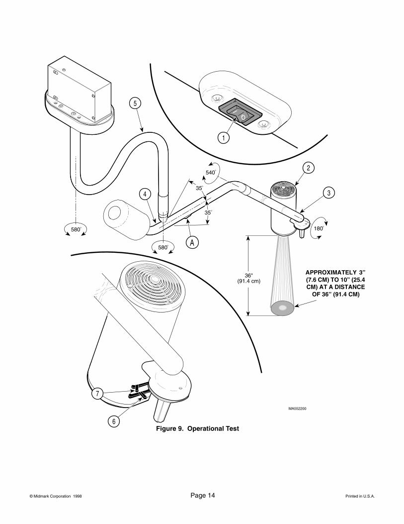
(1) Turn the ON / STANDBY switch (1, Figure 9) to ON “I”.
(2) Observe. The lighthead (2) should illuminate and the fan in the back of the lighthead should be operating.
Figure 7. Down Tube Installation
© Midmark Corporation 1998 Page 13 Printed in U.S.A.
(3) Position the lighthead (2) 36 in. (91.4 cm) from a table and aim the light beam at the table.
(4) Observe. There should be a circular pattern of bright light on the table surface.
(5) Rotate the lighthead (2), lamp tube (3), cross tube (4), and down tube (5) through their range of motions as shown on the illustration. Release the lighthead at different positions.
(6) Observe. The lighthead (2) should be able to be positioned easily through the entire range of its motion. When the lighthead is released in any position, no drifting should occur at any axis.
(7) Adjust the brightness control lever (6) through its range of motion.
(8) Observe. The light beam should brighten / darken as the brightness control lever (6) is adjusted.
(9) Adjust the brightness control lever (6) to achieve maximum brightness, then adjust the beam size lever (7) through its range of motion.
(10) Observe. The light beam pattern should change from approximately 3 in. to 10 in. (7.6 to 25.4 cm) as the beam size lever (7) is adjusted.
(11) If any problems are discovered, refer to the trou-bleshooting guide for adjustment and repair tips.
TROUBLESHOOTING
TROUBLESHOOTING GUIDE
If any problems are discovered during the installation process, refer to the following table (Table 1) to deter-mine the cause of the problem.
Figure 8. Cross Tube Assembly Installation
Table 1. Troubleshooting Guide
PROBLEM POSSIBLE CAUSE SOLUTION
no light from lighthead lighthead is on STAND-
BY “ “
turn ON / STANDBY switch to ON “I”
no light from lighthead, but ON / STANDBY switch is ON “I”
bulb has burned out or has not been installed
refer to bulb replacement procedure in this manual
fuse in junction box is blown
inspect / replace the fuse located inside the ceiling cover
no power to the junction box
check for facility power to the junction box
transformer is malfunc-tioning
check for 20.8 VAC output at the transformer when it is under load.
© Midmark Corporation 1998 Page 14 Printed in U.S.A.
6
7
36"(91.4 cm)
A
1
2
34
5
MA552200
580
580
540
180
35
35
Figure 9. Operational Test
APPROXIMATELY 3” (7.6 CM) TO 10” (25.4 CM) AT A DISTANCE
OF 36” (91.4 CM)
© Midmark Corporation 1998 Page 15 Printed in U.S.A.
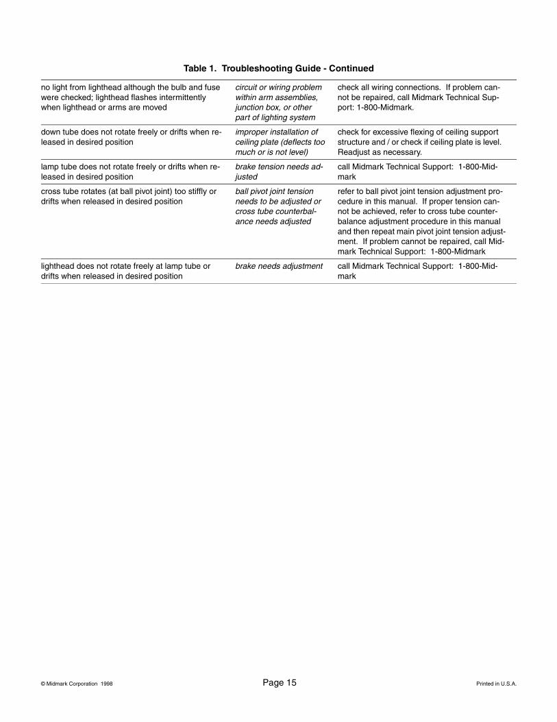
no light from lighthead although the bulb and fuse were checked; lighthead flashes intermittently when lighthead or arms are moved
circuit or wiring problem within arm assemblies, junction box, or other part of lighting system
check all wiring connections. If problem can-not be repaired, call Midmark Technical Sup-port: 1-800-Midmark.
down tube does not rotate freely or drifts when re-leased in desired position
improper installation of ceiling plate (deflects too much or is not level)
check for excessive flexing of ceiling support structure and / or check if ceiling plate is level. Readjust as necessary.
lamp tube does not rotate freely or drifts when re-leased in desired position
brake tension needs ad-justed
call Midmark Technical Support: 1-800-Mid-mark
cross tube rotates (at ball pivot joint) too stiffly or drifts when released in desired position
ball pivot joint tension needs to be adjusted or cross tube counterbal-ance needs adjusted
refer to ball pivot joint tension adjustment pro-cedure in this manual. If proper tension can-not be achieved, refer to cross tube counter-balance adjustment procedure in this manual and then repeat main pivot joint tension adjust-ment. If problem cannot be repaired, call Mid-mark Technical Support: 1-800-Midmark
lighthead does not rotate freely at lamp tube or drifts when released in desired position
brake needs adjustment call Midmark Technical Support: 1-800-Mid-mark
Table 1. Troubleshooting Guide - Continued
© Midmark Corporation 1998 Page 16 Printed in U.S.A.
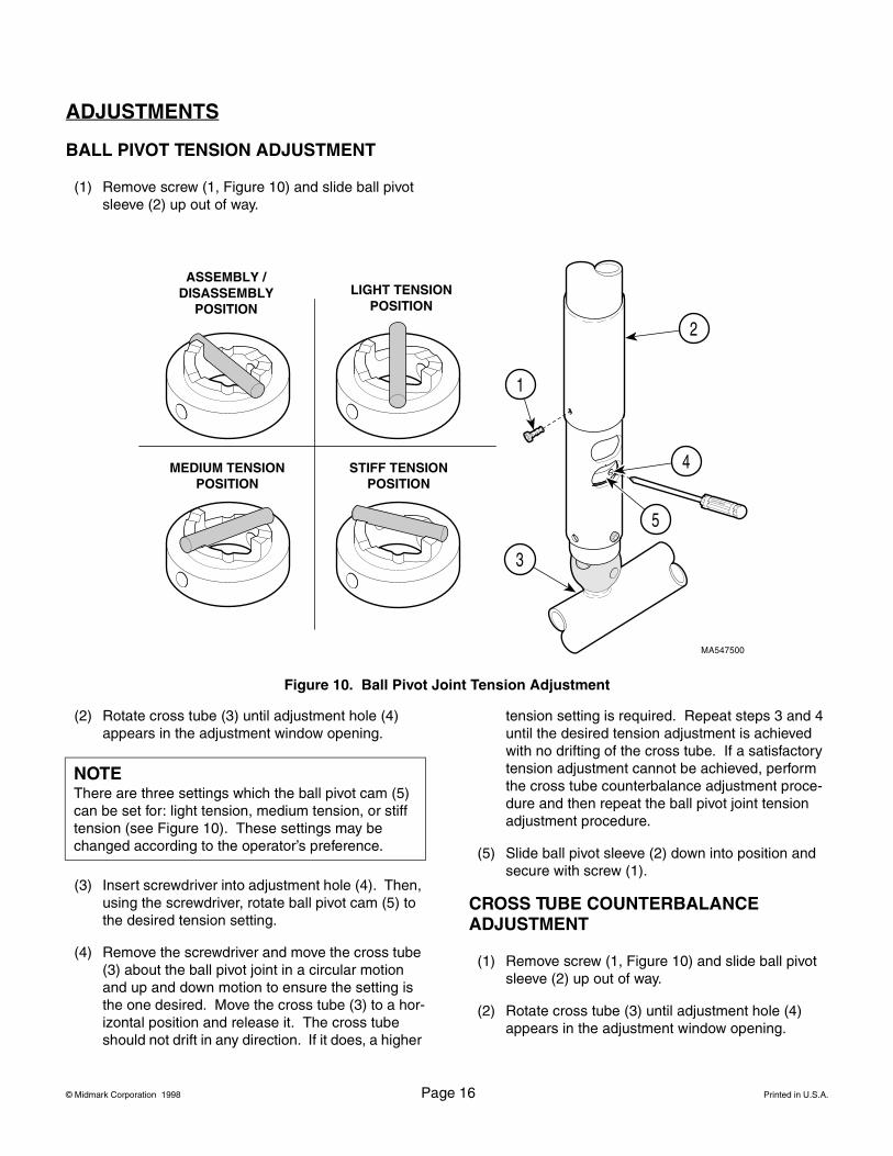
ADJUSTMENTS
BALL PIVOT TENSION ADJUSTMENT
(1) Remove screw (1, Figure 10) and slide ball pivot sleeve (2) up out of way.
(2) Rotate cross tube (3) until adjustment hole (4) appears in the adjustment window opening.
(3) Insert screwdriver into adjustment hole (4). Then, using the screwdriver, rotate ball pivot cam (5) to the desired tension setting.
(4) Remove the screwdriver and move the cross tube (3) about the ball pivot joint in a circular motion and up and down motion to ensure the setting is the one desired. Move the cross tube (3) to a hor-izontal position and release it. The cross tube should not drift in any direction. If it does, a higher
tension setting is required. Repeat steps 3 and 4 until the desired tension adjustment is achieved with no drifting of the cross tube. If a satisfactory tension adjustment cannot be achieved, perform the cross tube counterbalance adjustment proce-dure and then repeat the ball pivot joint tension adjustment procedure.
(5) Slide ball pivot sleeve (2) down into position and secure with screw (1).
CROSS TUBE COUNTERBALANCE ADJUSTMENT
(1) Remove screw (1, Figure 10) and slide ball pivot sleeve (2) up out of way.
(2) Rotate cross tube (3) until adjustment hole (4) appears in the adjustment window opening.
Figure 10. Ball Pivot Joint Tension Adjustment
ASSEMBLY / DISASSEMBLY
POSITIONLIGHT TENSION
POSITION
MEDIUM TENSIONPOSITION
STIFF TENSIONPOSITION
NOTEThere are three settings which the ball pivot cam (5) can be set for: light tension, medium tension, or stiff tension (see Figure 10). These settings may be changed according to the operator’s preference.
© Midmark Corporation 1998 Page 17 Printed in U.S.A.
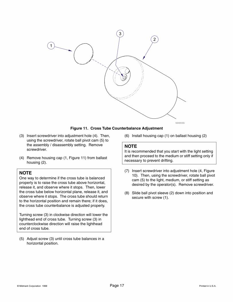
(3) Insert screwdriver into adjustment hole (4). Then, using the screwdriver, rotate ball pivot cam (5) to the assembly / disassembly setting. Remove screwdriver.
(4) Remove housing cap (1, Figure 11) from ballast housing (2).
(5) Adjust screw (3) until cross tube balances in a horizontal position.
(6) Install housing cap (1) on ballast housing (2)
(7) Insert screwdriver into adjustment hole (4, Figure 10). Then, using the screwdriver, rotate ball pivot cam (5) to the light, medium, or stiff setting as desired by the operator(s). Remove screwdriver.
(8) Slide ball pivot sleeve (2) down into position and secure with screw (1).
Figure 11. Cross Tube Counterbalance Adjustment
NOTEOne way to determine if the cross tube is balanced properly is to raise the cross tube above horizontal, release it, and observe where it stops. Then, lower the cross tube below horizontal plane, release it, and observe where it stops. The cross tube should return to the horizontal position and remain there; if it does, the cross tube counterbalance is adjusted properly.
Turning screw (3) in clockwise direction will lower the lighthead end of cross tube. Turning screw (3) in counterclockwise direction will raise the lighthead end of cross tube.
NOTEIt is recommended that you start with the light setting and then proceed to the medium or stiff setting only if necessary to prevent drifting.
© Midmark Corporation 1998 Page 18 Printed in U.S.A.
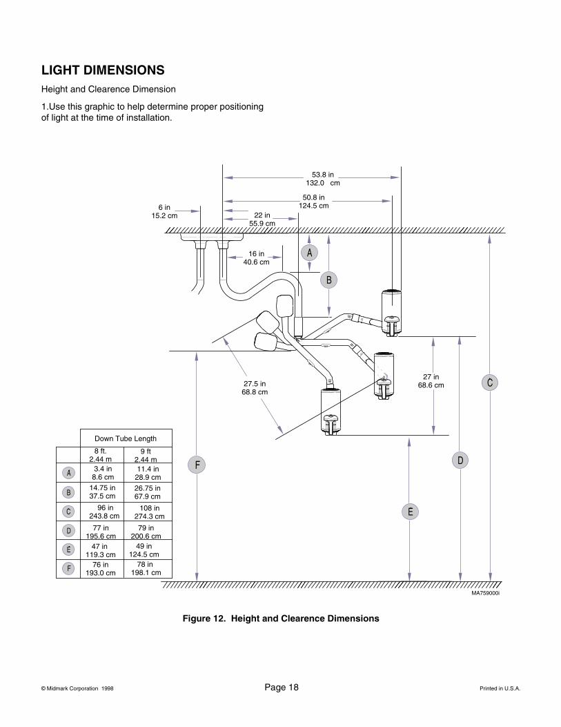
LIGHT DIMENSIONSHeight and Clearence Dimension
1.Use this graphic to help determine proper positioning of light at the time of installation.
6 in15.2 cm
53.8 in132.0 cm
50.8 in124.5 cm
22 in55.9 cm
27.5 in68.8 cm
27 in68.6 cm
8 ft.2.44 m
Down Tube Length
9 ft2.44 m
3.4 in8.6 cm
11.4 in28.9 cm
96 in243.8 cm
108 in274.3 cm
77 in 195.6 cm
47 in 119.3 cm
79 in 200.6 cm
49 in124.5 cm
76 in 193.0 cm
78 in 198.1 cm
14.75 in37.5 cm
26.75 in67.9 cm
16 in40.6 cm
MA759000i
Figure 12. Height and Clearence Dimensions

© Midmark Corporation 1998 Page 19 Printed in U.S.A.
CALLING FOR SERVICE
If you are having a problem or have a question, refer to the inside front cover of this manual and call your dealer. Make sure that you have the information that is highlighted on the inside front cover of this manual avail-able. If you can’t resolve your question or problem with your dealer, call the following number:
1-800-Midmark (1-800-643-6275) or 937-526-36628:00 a.m until 5:00 p.m. (Eastern Standard Time in U.S.)Monday through Friday, except for standard U.S. holidays.
LIMITED WARRANTY
SCOPE OF WARRANTYMidmark Corporation (“Midmark”) warrants to the original purchaser its new Alternate Care products and compo-nents (except for components not warranted under “Exclu-sions”) manufactured by Midmark to be free from defects in material and workmanship under normal use and service. Midmark’s obligation under this warranty is limited to the repair or replacement, at Midmark’s option, of the parts or the products the defects of which are reported to Midmark within the applicable warranty period and which, upon examination by Midmark, prove to be defective.
APPLICABLE WARRANTY PERIODThe applicable warranty period, measured from the date of delivery to the original user, shall be one (1) year for all warranted products and components.
EXCLUSIONSThis warranty does not cover and Midmark shall not be lia-ble for the following: (1) repairs and replacements because of misuse, abuse, negligence, alteration, acci-dent, freight damage, or tampering; (2) products which are not installed, used, and properly cleaned as required in the Midmark “Installation” and or “Installation / Operation Man-ual for this applicable product. (3) products considered to be of a consumable nature; (4) accessories or parts not manufactured by Midmark; (5) charges by anyone for adjustments, repairs, replacement parts, installation, or other work performed upon or in connection with such products which is not expressly authorized in writing in advance by Midmark.
EXCLUSIVE REMEDYMidmark’s only obligation under this warranty is the repair or replacement of defective parts. Midmark shall not be liable for any direct, special, indirect, incidental, exemplary, or consequential damages or delay, including, but not lim-ited to, damages for loss of profits or loss of use.
NO AUTHORIZATIONNo person or firm is authorized to create for Midmark any other obligation or liability in connection with the products.
THIS WARRANTY IS MIDMARK’S ONLY WARRANTY AND IS IN LIEU OF ALL OTHER WARRANTIES, EXPRESS OR IMPLIED. MIDMARK MAKES NO IMPLIED WARRANTIES OF ANY KIND INCLUDING ANY WARRANTIES OF MERCHANTABILITY OR FITNESS FOR ANY PARTICULAR PURPOSE. THIS WARRANTY IS LIMITED TO THE REPAIR OR REPLACEMENT OF DEFECTIVE PARTS.
SF-1487 REV. A1


© Midmark Corporation - 1999
003-1067-00 Rev. P (5/21/13)
Midmark Corporation
60 Vista Drive
Versailles, OH 45380 USA
1-800-643-6275
1-937-526-3662www.midmark.com
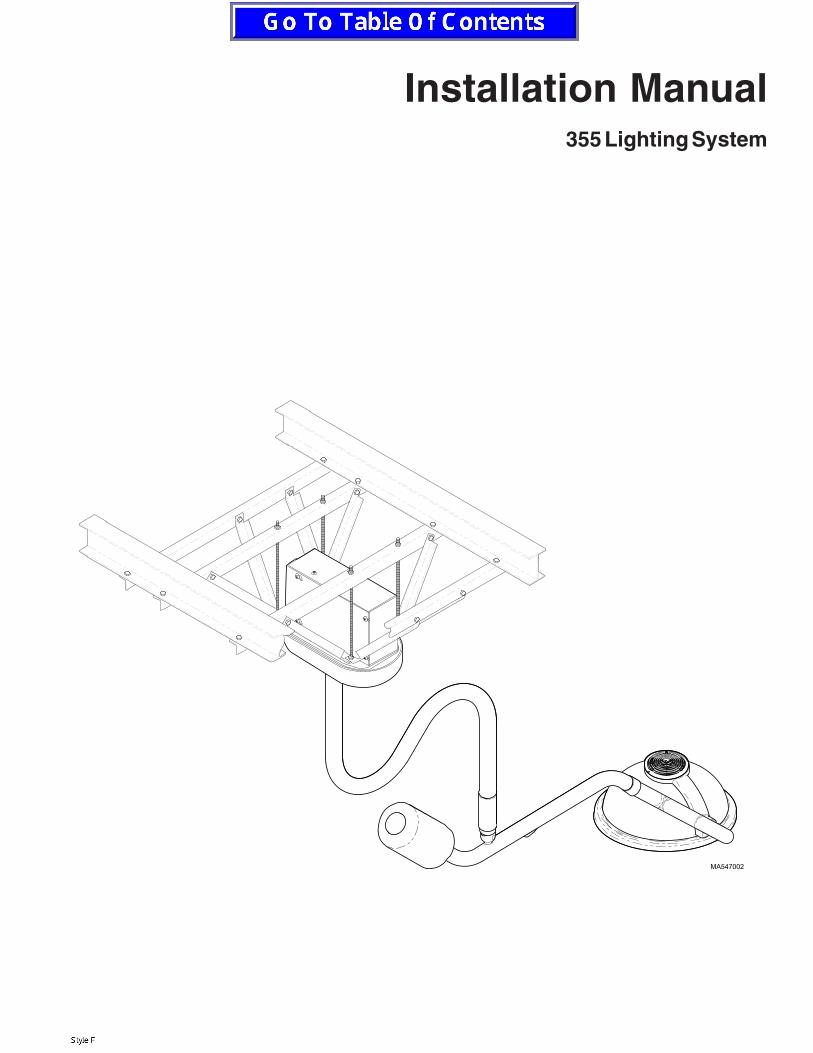
Installation Manual355 Lighting System
MA547100
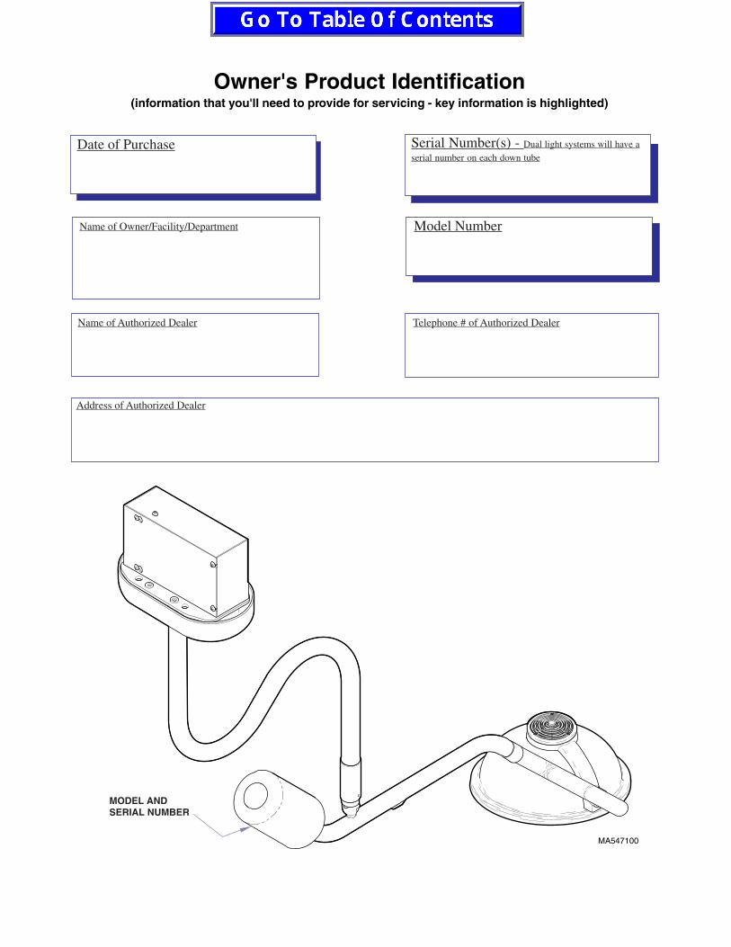
Owner's Product Identification(information that you'll need to provide for servicing - key information is highlighted)
Date of Purchase Serial Number(s) - Dual light systems will have a
serial number on each down tube
Model Number
Name of Authorized Dealer Telephone # of Authorized Dealer
Address of Authorized Dealer
Name of Owner/Facility/Department
MODEL ANDSERIAL NUMBER

Table of Contents
IMPORTANT INFORMATIONScope And Purpose of this Manual ........................................................ 2
Safety Instructions .................................................................................. 2
Safety Symbols and Notes ..................................................................... 2
Transportation and Storage Conditions .................................................. 2
GENERAL INFORMATIONLighting System ...................................................................................... 3
Specifications ......................................................................................... 3
Range of Motion ..................................................................................... 4
355 LIGHTING SYSTEM INSTALLATIONUnpacking ............................................................................................... 5
Recommended Ceiling Mounting Locations (For Dental & andMedical Applications) ........................................................................ 6
Ceiling Support Structure Installation ..................................................... 6
Electromagnetic Interference .................................................................. 8
Wiring Installation ................................................................................... 8
Junction Box Wiring Connections ........................................................... 8
Ceiling Plate Assembly Installation ....................................................... 11
Down Tube Installation .......................................................................... 12
Cross Tube Assembly Installation ......................................................... 13
Bulb Installation .................................................................................... 14
Housing Cap Installation ....................................................................... 15
Operational Test .................................................................................... 15
TROUBLESHOOTINGTroubleshooting Guide .......................................................................... 16
ADJUSTMENTSBall Pivot Joint Tension Adjustment ...................................................... 17
Cross Tube Counterbalance Adjustment .............................................. 18
LIGHT DIMENSIONSHeight and Clearence Dimension ......................................................... 19
CALLING FOR SERVICE ........................................................................ 19LIMITED WARRANTY ............................................................................. 20

2
IMPORTANT INFORMATION
Scope and Purpose of Manual
This manual covers complete instructions for theinstallation of the 355 Lighting System and is intended tobe used by personnel involved in the installation of the355 Lighting System. The Operation Manual for the 355Lighting System is a separate document and is intendedfor persons who will operate the 355 Lighting System.
Safety Instructions
The primary concern of Midmark is that this equipmentbe operated and maintained with the safety of the usersin mind. To assure safer and more reliable operation, dothe following: (1) Read this manual before installing yourlight assembly; (2) Assure that appropriate personnel areinformed on the contents of this manual--this is theresponsibility of the purchaser; (3) Be sure that youunderstand the instructions contained in this manualbefore attempting to install this light assembly; (4) Besure that you have read and understand the instructionscontained in the Operation Manual (a separate docu-ment) before attempting to operate this equipment.
Safety Symbols and Notes
Throughout this manual, there are danger, warning,caution, equipment alerts, and notes that call attention toparticular procedures. The signal words and notes areused as follows:
DANGERIndicates an imminently hazardoussituation, which, if not avoided, will
result in death or serious injury. This signal wordis limited to the most extreme situations.
WARNINGIndicates a potentially hazardous situation, which, if not avoided, could result
in death or serious injury.
CAUTIONIndicates a potentially hazardous situation, which, if not avoided, may result in
minor or moderate injury. It may also be used toalert against unsafe practices.
EQUIPMENT ALERTIndicates an imminently or potentiallyhazardous situation, which, if not avoided,
will or may result in serious, moderate, or minorequipment damage.
NOTENote is used to amplify an operating procedure,practice, or condition.
Indicates that the unit is rated: Type B, AppliedPart.
Indicates a protective earth ground.
Indicates that the operator's manual should beconsulted for important information.
Indicates the product is fragile; do not handleroughly.
Indicates the proper shipping orientation for theproduct.
Indicates the presence of a dangerous voltage /shock hazard.
Indicates the product must be kept dry.
Indicates a fuse rating specification.
Indicates a hot surface.
Transportation and Storage Conditions
Ambient Temperature Range: ................. -30oC to +60oC
(-22oF to 140oF)Relative Humidity: ........... 10% to 90% (non-condensing)Atmospheric Pressure: ..................500 hPa to 1060 hPa
(0.5 bar to 1.06 bar)
This product contains glass, so it should be transportedand stored with care to limit vibration and shocks.
VA
3
GENERAL INFORMATION
Lighting System
The 355 lighthead assembly is a fixed-focus, facetedreflector lighthead. The faceted reflector design of thelighthead provides excellent cavity penetration, while alsocontrolling shadows from light-blocking objects. Thedesign also results in bright, even distribution of light.The individual beams of light are arranged to provide anevenly illuminated 8 inch diameter beam at a distance of36 inches. The peak illumination at 36 inches is 4,000 fc(43,000 lux). The optical system filters out most of theinfrared heat from the prefocused pattern of light. Theplastic handle can be easily removed for sterilization or itaccepts a Devon EZ HandleTM without requiring anawkward adapter. The lighthead is made with a colormolded, lightweight polymer resulting in a very light-weight lighthead which is easy to position. The opticalsystem is powered by a 24 VAC, 100 Watt bulb. The armassemblies (suspension system) have been preciselydesigned, assembled, and balanced so that the lightheadcan be positioned with minimal force with no driftingoccuring. In addition, the three pivots with 540o ofrotation make the positioning of the lighthead easy andflexible.
Table 1. Model 355 Specifications
Beam diameter @ 36 inches: ........................................ 8" (defined by 20% of peak illumination)Bulb: ............................................................................... 100 W halogen lamp, 24 VACColor temperature: ........................................................ 4,200KDiameter of lighthead: ................................................... 17"Focal length: .................................................................. 36"Illumination: ................................................................... 3,400fc, 36,600 luxPower requirement: ....................................................... 120 VAC, 1.25 A, single phaseRotation of lighthead: ................................................... 180o rotation at lamp tube connectionRotation of lamp tube: .................................................. 540o rotation at cross tube connectionRotation of cross tube: ................................................. 580o rotation at down tube connectionVertical movement of cross tube: ................................ -35o to +35o vertical movementRotation of down tube: ................................................. 580o rotation at ceiling plate connectionWeight of 8 ft (2.44 m) single light assembly: ............. 59 lbs. (26.8 kgs.)Weight of 9 ft (2.74 m) single light assembly: ............. 60 lbs. (27.2 kgs.)Weight of 8 ft (2.44 m) dual light assembly: ................ 105 lbs. (47.6 kgs.)Weight of 9 ft (2.74 m) dual light assembly: ................ 107 lbs. (48.5 kgs.)Certifications: ................................................................ Classified by Underwriters Laboratories Inc. with respect to
electric shock, fire, and mechanical hazards only in accor-
dance with UL2601-1 and CAN/CSA C22.2, No.601.1.
ISO-9001 CertifiedClassifications: .............................................................. Class 1, Type B applied part, Ordinary Equipment,
Continuous OperationFuse Rating: ................................................................... 1.6 A, 250 V, Type T, low breaking capacity,
5mm x 20mm, IEC 127-2/3Equipment not suitable for use in the presence of a flammable anesthetic mixture with air, oxygen, or nitrous oxide.
94XM
Specifications
See Table 1 for specifications on the 355 LightingSystem.
4
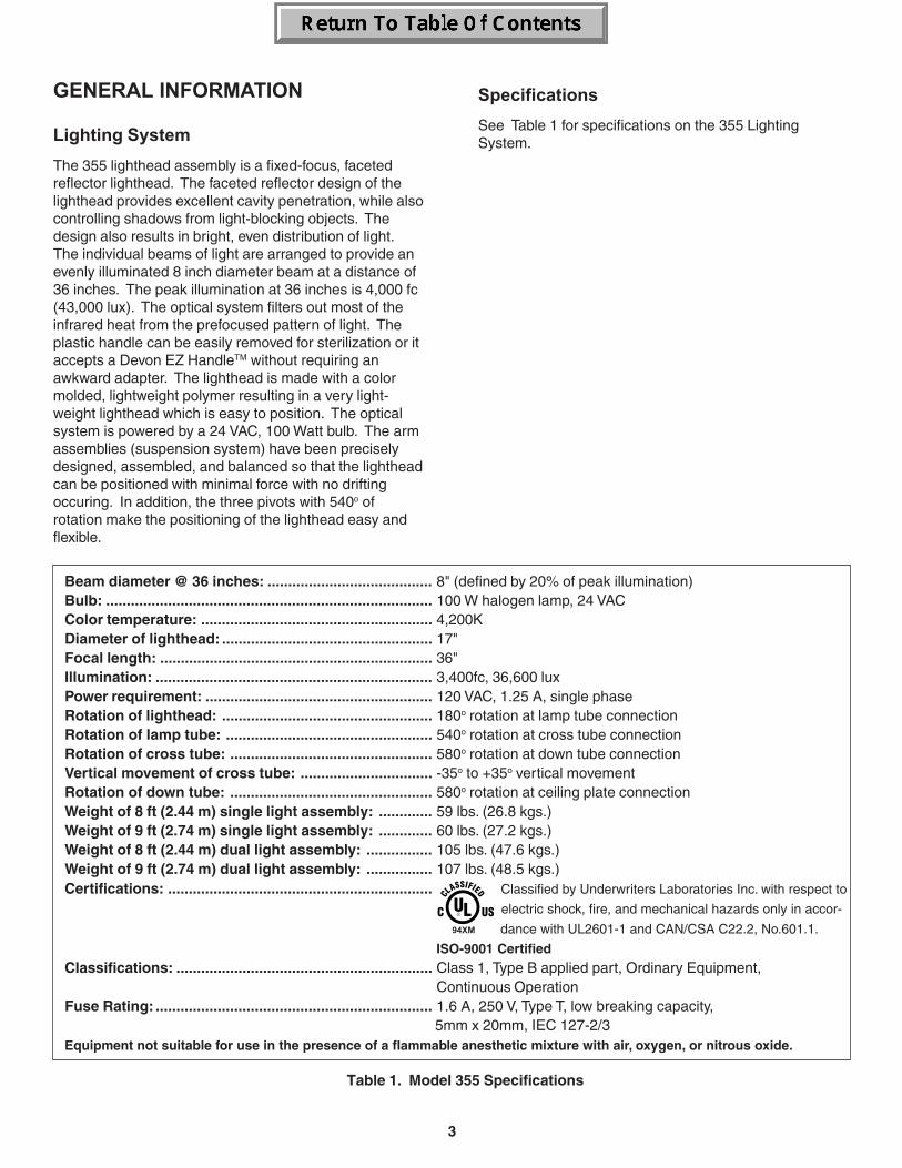
27.5 in.(69.8 cm)
49.5 in.(125.7 cm)
58.2 in.(147.8 cm)
MA551500
Height of Lighthead Assembly
9 Ft. Ceiling
Adjustable from less than 53 in. (135 cm) to
greater than 78 in. (198 cm) above floor.
8 Ft. Ceiling
Adjustable from less than 53 in. (135 cm) to
greater than 78 in. (198 cm) above floor.
Figure 1. Range of Motion
Range of Motion
5
2
1
4
3
MA9138i
5
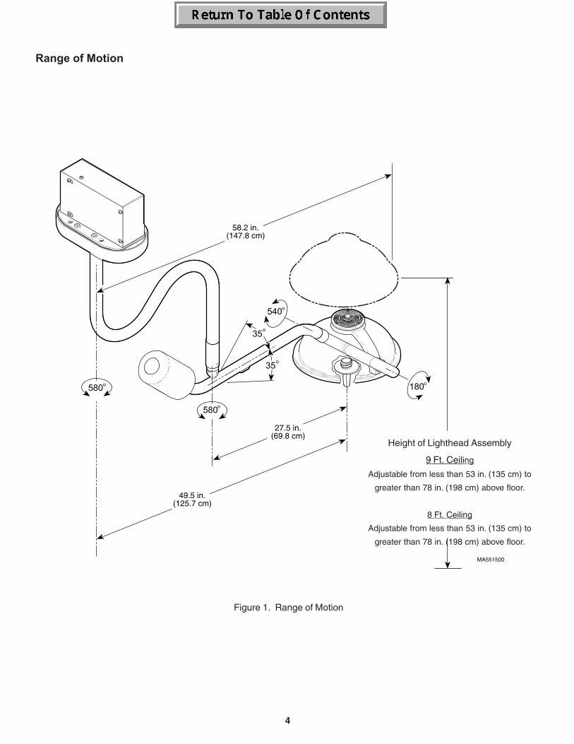
355 LIGHTING SYSTEMINSTALLATION
Unpacking
NOTEBelow is a list of all the items which should be in-cluded in the shipping box(es). The first quantityindicates the number of items which should be presentfor a single lighting assembly while the secondquantity indicates the number of items which shouldbe present for a dual lighting assembly (Refer toFigure 2).
1. Cut banding and remove box lid from box.
2. Remove one/two cross tube/lighthead assembly (1,Figure 2) and inspect.
3. Remove one/two down tube assembly (2) andinspect.
4. Remove one/two bag(s) (3) and inventory contents;the following items should be included:3a. Four #10-24 x 3/4" socket cap screws3b. Two/four #10-24 x 3/8" black oxide
button head screws3c. Six/twelve 3/8"-16 hex nuts3d. Three/six 3/8" lockwashers3e. One/two #10-24 x 5/8" zinc plated
button head screws3f. One/two #10-24 x 3/8" pan head screw3g. One/two 100 Watt Halogen bulb3h. One/two Sterilizable handle (inspect)
5. Remove one ceiling plate assembly (4) and inspect.
6. Remove one ceiling cover (5) and inspect.
Figure 2. Components Unpacking and Inventory
#10-24 x 3/4" Cap Screw (3a)
#10-24 x 3/8" Button Head Screw (3b)
#3/8"-16 Hex Nut (3c)
3/8" Lockwasher (3d)
100 W Halogen Bulb (3g)
#10-24 x 5/8" Button Head Screw (3e)
#10-24 x 3/8" Pan Head Screw (3f)
Sterilizable Handle (3h)
6
Ceiling Support Structure Installation
Weights:• 8 ft (2.44 m) Single 355 Lighting System
(less customer suppliedceiling structure): ...................... 59 lbs (26.8 kgs)
• 9 ft (2.74 m) Single 355 Lighting System(less customer suppliedceiling structure): ...................... 60 lbs (27.2 kgs)
• 8 ft (2.44 m) Dual 355 Lighting System(less customer suppliedceiling structure): .................... 105 lbs (47.6 kgs)
• 9 ft (2.74 m) Dual 355 Lighting System(less customer suppliedceiling structure): .................... 107 lbs (48.5 kgs)
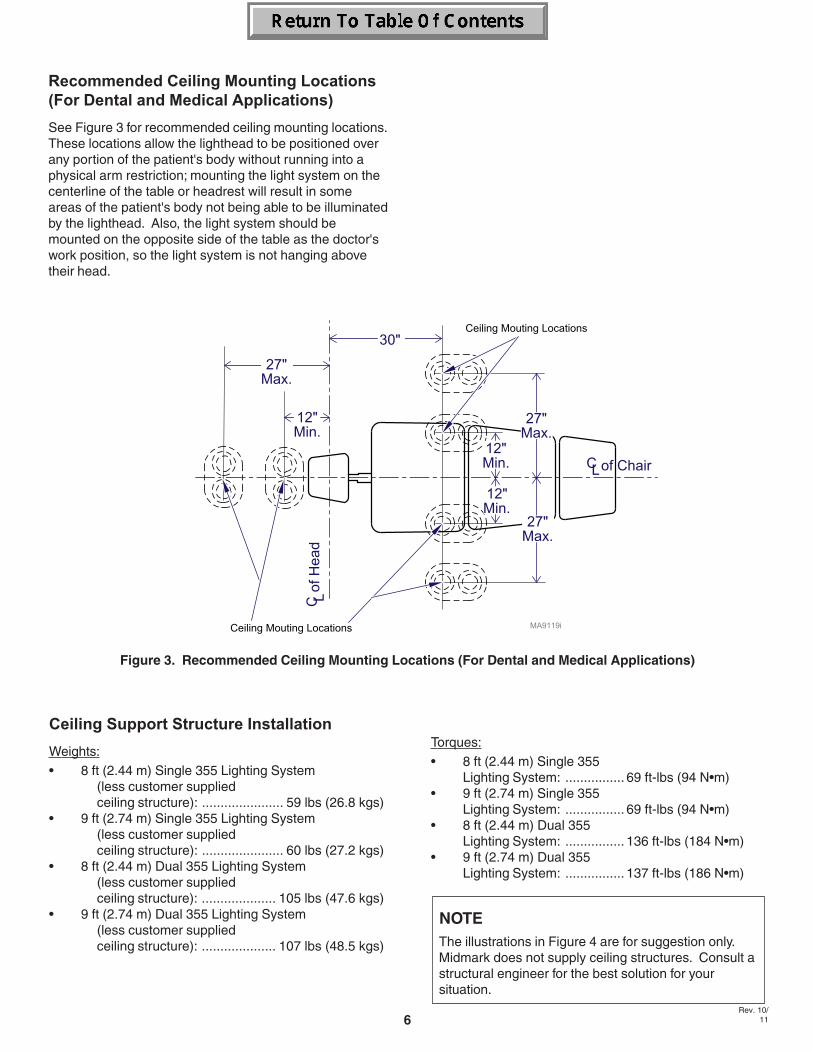
Figure 3. Recommended Ceiling Mounting Locations (For Dental and Medical Applications)
Rev. 10/11
Recommended Ceiling Mounting Locations(For Dental and Medical Applications)
See Figure 3 for recommended ceiling mounting locations.These locations allow the lighthead to be positioned overany portion of the patient's body without running into aphysical arm restriction; mounting the light system on thecenterline of the table or headrest will result in someareas of the patient's body not being able to be illuminatedby the lighthead. Also, the light system should bemounted on the opposite side of the table as the doctor'swork position, so the light system is not hanging abovetheir head.
Torques:• 8 ft (2.44 m) Single 355
Lighting System: ................ 69 ft-lbs (94 N•m)• 9 ft (2.74 m) Single 355
Lighting System: ................ 69 ft-lbs (94 N•m)• 8 ft (2.44 m) Dual 355
Lighting System: ................ 136 ft-lbs (184 N•m)• 9 ft (2.74 m) Dual 355
Lighting System: ................ 137 ft-lbs (186 N•m)
NOTEThe illustrations in Figure 4 are for suggestion only.Midmark does not supply ceiling structures. Consult astructural engineer for the best solution for yoursituation.
7
MA547700
76.2 cm(30")
3.8 cm - 5.1 cm(1 1/2" - 2")
1.9 cm(3/4")
18.4 cm(7.24")
15.2 cm(6.00")
29.2 cm(11.50")
10.8 cm(4.25")
7.6 cm(3.00")
15.2 cm(6.00")
1.3 cm(1/2")
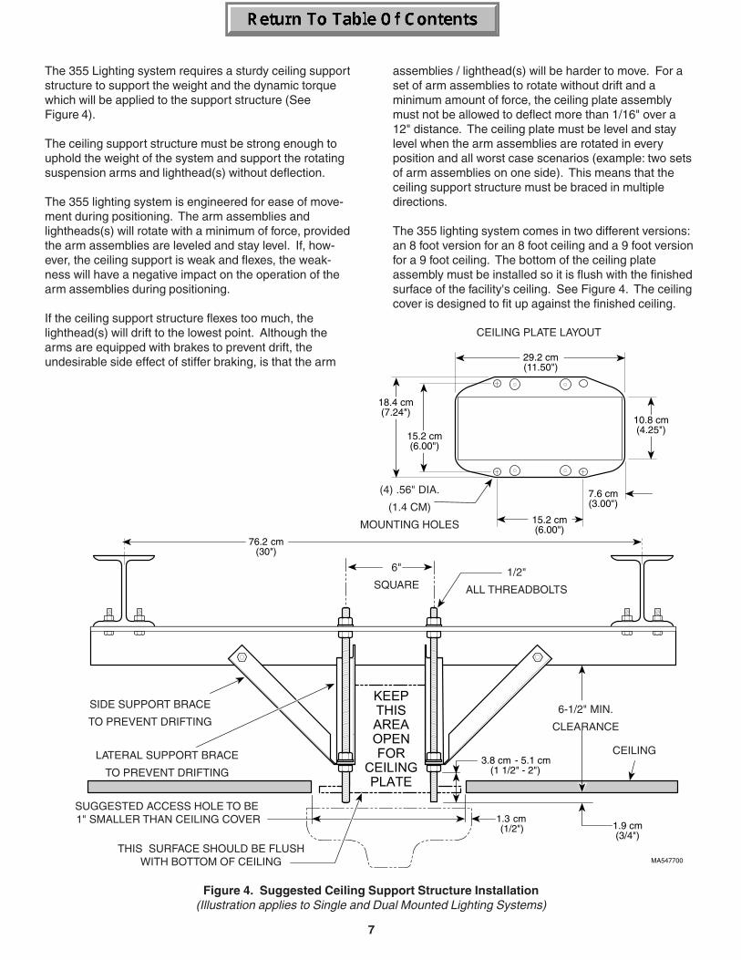
assemblies / lighthead(s) will be harder to move. For aset of arm assemblies to rotate without drift and aminimum amount of force, the ceiling plate assemblymust not be allowed to deflect more than 1/16" over a12" distance. The ceiling plate must be level and staylevel when the arm assemblies are rotated in everyposition and all worst case scenarios (example: two setsof arm assemblies on one side). This means that theceiling support structure must be braced in multipledirections.
The 355 lighting system comes in two different versions:an 8 foot version for an 8 foot ceiling and a 9 foot versionfor a 9 foot ceiling. The bottom of the ceiling plateassembly must be installed so it is flush with the finishedsurface of the facility's ceiling. See Figure 4. The ceilingcover is designed to fit up against the finished ceiling.
Figure 4. Suggested Ceiling Support Structure Installation(Illustration applies to Single and Dual Mounted Lighting Systems)
CEILING PLATE LAYOUT
(4) .56" DIA.
(1.4 CM)
MOUNTING HOLES
SIDE SUPPORT BRACE
TO PREVENT DRIFTING
LATERAL SUPPORT BRACE
TO PREVENT DRIFTING
6"
SQUARE1/2"
ALL THREADBOLTS
6-1/2" MIN.
CLEARANCE
CEILING
THIS SURFACE SHOULD BE FLUSHWITH BOTTOM OF CEILING
SUGGESTED ACCESS HOLE TO BE 1" SMALLER THAN CEILING COVER
The 355 Lighting system requires a sturdy ceiling supportstructure to support the weight and the dynamic torquewhich will be applied to the support structure (SeeFigure 4).
The ceiling support structure must be strong enough touphold the weight of the system and support the rotatingsuspension arms and lighthead(s) without deflection.
The 355 lighting system is engineered for ease of move-ment during positioning. The arm assemblies andlightheads(s) will rotate with a minimum of force, providedthe arm assemblies are leveled and stay level. If, how-ever, the ceiling support is weak and flexes, the weak-ness will have a negative impact on the operation of thearm assemblies during positioning.
If the ceiling support structure flexes too much, thelighthead(s) will drift to the lowest point. Although thearms are equipped with brakes to prevent drift, theundesirable side effect of stiffer braking, is that the arm
8
Electromagnetic Interference
This product is designed and built to minimizeelectrmagnetic interference with other devices. However,if interference is noticed between another device and thisproduct, remove the interfering device from the room orwire this product into an isolated circuit.
Wiring Installation
The wiring, supplying power to the junction box of the355 lighting system, must be supplied by the customer.The 355 lighting system requires 120 VAC input voltage.The wire should be 2-conductor with ground, 14 gaugecopper wiring, rated for 120 VAC. The customer suppliedwiring must be connected to the junction box with someform of strain relief fitting, preferably a conduit fitting.Connect and route the wiring according to state and localcodes, using conduit where necessary. See wiringdiagram, Figure 5.
Junction Box Wiring Connections (SeeFigure 5, sheets 1 and 2)
WARNINGMake sure facility supplied wiring isturned to off for the following step.
Failure to do so could result in electrical shockcausing serious personal injury or death.
1. Turn off facility power breaker so there is no powerin customer supplied wiring.
2. Loosen four screws (1, Figure 7); then pull outwardon box cover (2) and remove from junction box (3).
3. Install conduit fitting (customer supplied) in theknockout of the junction box (3).
4. Feed the facility supplied wiring through the knock-out in the junction box (3).
WARNINGMake sure facility supplied wiring is notshorted to junction box and do not
touch wires during steps 5 and 6. Failure to do socould result in electrical shock causing seriouspersonal injury or death.
5. Turn on facility power breaker so there is power incustomer supplied wiring.
6. Using a multimeter, measure the input voltagebetween black power lead and white neutral lead ofcustomer supplied wiring. Record this voltage. SeeFigure 5.
WARNINGMake sure facility supplied wiring isturned to off for the following step.
Failure to do so could result in electrical shockcausing serious personal injury or death.
7. Turn off facility power breaker so there is no powerin customer supplied wiring.
8. If voltage measured in step 6 was 117.0 VAC orlower, connect the white neutral lead of customersupplied wiring to the terminal marked N/114V forsingle units or N1/114V or N2/114V for double units(see Figure 5).
If voltage measured in step 6 was between 117.1to 123.0 VAC, connect the white neutral lead ofcustomer supplied wiring to the terminal marked N/120V for single units or N1/120V or N2/120V fordouble units (see Figure 5).
If voltage measured in step 6 was 123.1 VAC orhigher, connect the white neutral lead of customersupplied wiring to the terminal marked N/126V forsingle units or N1/126V or N2/126V for double units(see Figure 5).
9. Connect the black power wire from customersupplied wiring to the terminal marked L.
10. Connect the green earth ground wire from customersupplied wiring to the terminal marked with aground symbol.
CAUTIONFailure to properly connect and insulatewires in junction box could result in a
short or electrical shock to personnel or impropersystem operation.• Always use a strain relief (conduit fitting)
between facility wiring and the junction box.• Always connect the earth ground wires inside
the junction box.• Double Units - Always make certain the white
jumper wire is properly positioned.
11. If light system is a dual light, the white jumper wireon the terminal block may need to be repositioneddepending on the voltage measurement taken instep 6. If the voltage measurement was 117.0 VACor lower, use white jumper wire to connect N1/114Vto N2/114V. If the voltage measurement was 117.1VAC to 123.0 VAC, keep white jumper wire where itis; connecting N1/120V to N2/120V. If the voltagemeasurement was 123.1 VAC or higher, use whitejumper wire to connect N1/126V to N2/126V.
9
NOTEIt is especially important to perform steps 12 and 13now if the ceiling is a drywall/plastered ceiling; thesesteps cannot be performed later.
12. Feed brown and blue transformer output wires outof wire hole (7, Figure 7) in bottom of junction box.
13. Position box cover (2) on junction box (3) andsecure by tightening four screws (1).
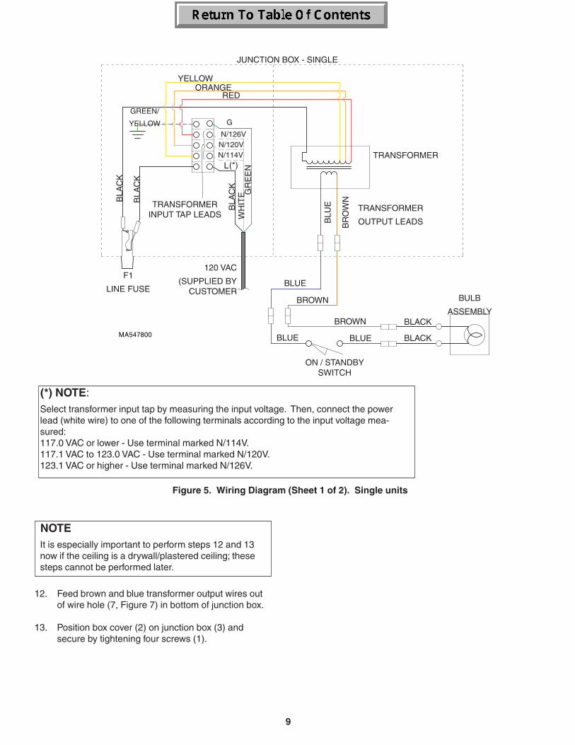
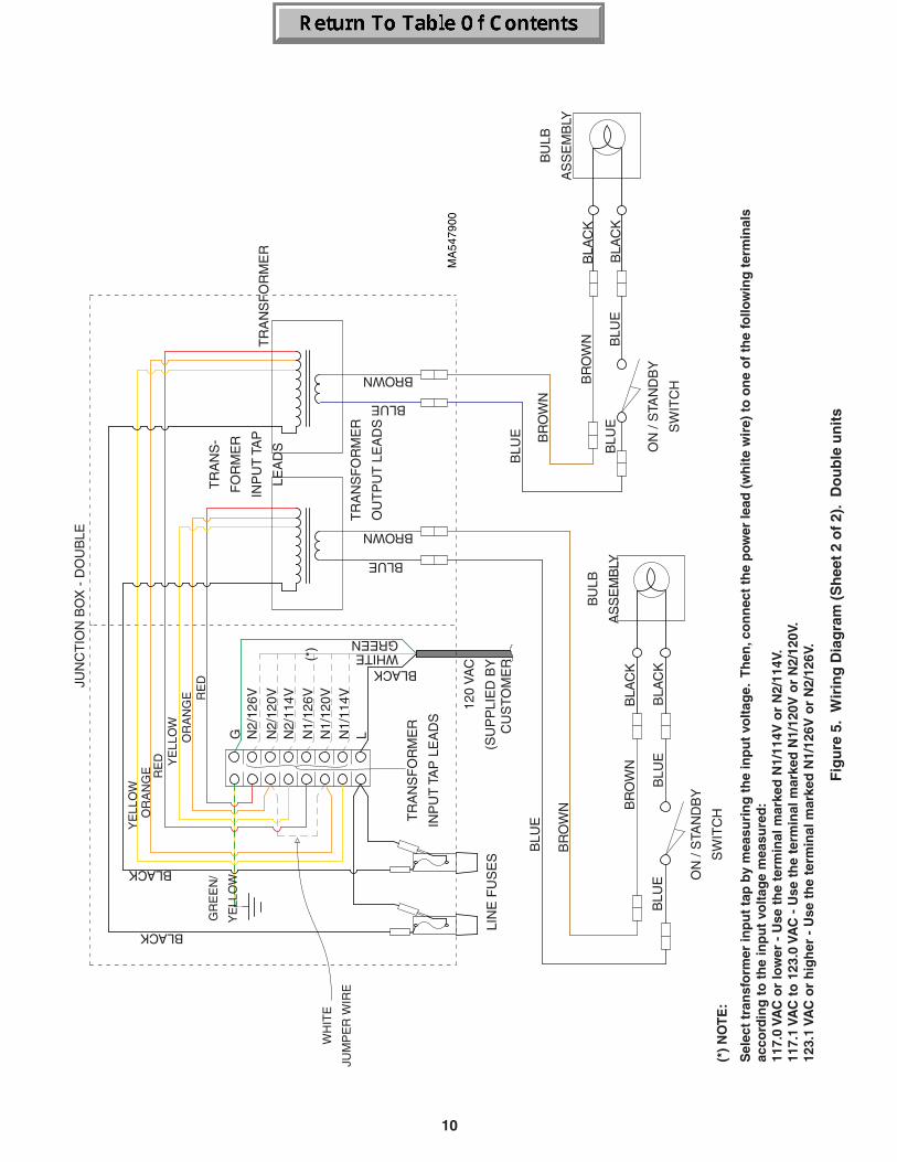
Figure 5. Wiring Diagram (Sheet 1 of 2). Single units
(*) NOTE:Select transformer input tap by measuring the input voltage. Then, connect the powerlead (white wire) to one of the following terminals according to the input voltage mea-sured:117.0 VAC or lower - Use terminal marked N/114V.117.1 VAC to 123.0 VAC - Use terminal marked N/120V.123.1 VAC or higher - Use terminal marked N/126V.
JUNCTION BOX - SINGLE
TRANSFORMERINPUT TAP LEADS
BULB
ASSEMBLYBLACK
BLACK
BROWN
BLUEBLUE
BLUE
BROWN
BR
OW
N
YELLOW
REDORANGE
BLU
E
TRANSFORMER
F1
LINE FUSE
120 VAC
(SUPPLIED BYCUSTOMER
ON / STANDBYSWITCH
TRANSFORMER
OUTPUT LEADS
GREEN/
YELLOWB
LAC
K
BLA
CK
BLA
CK
WH
ITE G
RE
EN(*)
N/126VN/120VN/114V
G
L
10
Fig
ure
5.
Wir
ing
Dia
gra
m (
Sh
eet
2 o
f 2)
. D
ou
ble
un
its
(*)
NO
TE
:
Sel
ect
tran
sfo
rmer
inp
ut
tap
by
mea
suri
ng
th
e in
pu
t vo
ltag
e. T
hen
, co
nn
ect
the
pow
er le
ad (
wh
ite
wir
e) t
o o
ne
of
the
follo
win
g t
erm
inal
sac
cord
ing
to
th
e in
pu
t vo
ltag
e m
easu
red
:11
7.0
VAC
or
low
er -
Use
th
e te
rmin
al m
arke
d N
1/11
4V o
r N
2/11
4V.
117.
1 VA
C t
o 1
23.0
VA
C -
Use
th
e te
rmin
al m
arke
d N
1/12
0V o
r N
2/12
0V.
123.
1 VA
C o
r h
igh
er -
Use
th
e te
rmin
al m
arke
d N
1/12
6V o
r N
2/12
6V.
JUN
CT
ION
BO
X -
DO
UB
LE
TR
AN
S-
FO
RM
ER
INP
UT
TA
P
LEA
DS
BLA
CK
BLA
CK
BR
OW
N BLU
E
BROWN
BLUE
LIN
E F
US
ES
120
VA
C
(SU
PP
LIE
D B
YC
US
TOM
ER
TR
AN
SF
OR
ME
R
OU
TP
UT
LE
AD
S
GR
EE
N/
YE
LLO
W
BLACK
BLACK
BU
LB
AS
SE
MB
LY
ON
/ S
TAN
DB
Y
SW
ITC
H
YE
LLO
W
RE
DO
RA
NG
E
TR
AN
SF
OR
ME
R
BLACKWHITEGREEN
(*)
N2/
126V
N2/
120V
N2/
114V
G L
BR
OW
N
BLU
E
BLU
E
N1/
126V
N1/
120V
N1/
114V
YE
LLO
W
RE
DO
RA
NG
E
WH
ITE
JUM
PE
R W
IRE
BLA
CK
BLA
CK
BR
OW
N
BLU
E
BR
OW
N
BLU
E
BLU
E
BROWN
BLUEB
ULB
AS
SE
MB
LY
TR
AN
SF
OR
ME
R
INP
UT
TA
P L
EA
DS
ON
/ S
TAN
DB
Y
SW
ITC
H
11
5
1
3
2
4
MA32850
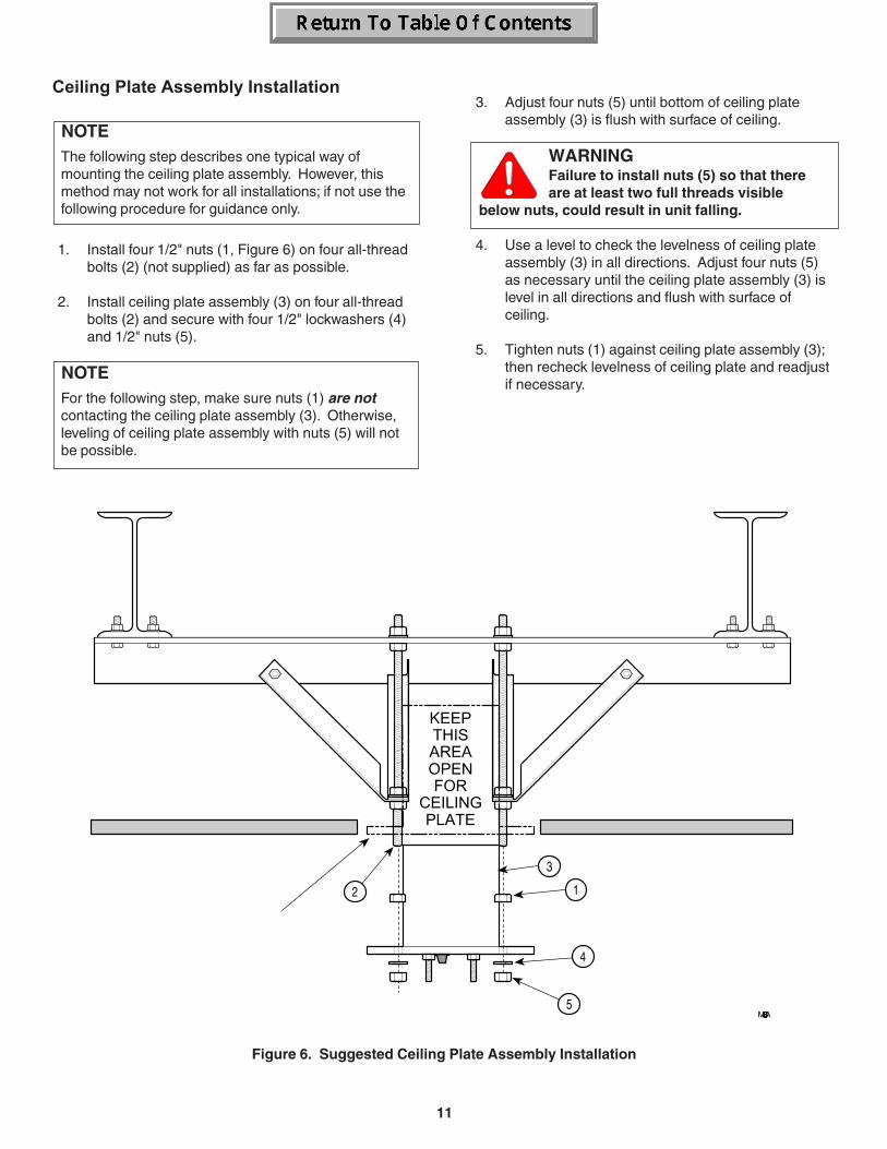
Ceiling Plate Assembly Installation
NOTEThe following step describes one typical way ofmounting the ceiling plate assembly. However, thismethod may not work for all installations; if not use thefollowing procedure for guidance only.
1. Install four 1/2" nuts (1, Figure 6) on four all-threadbolts (2) (not supplied) as far as possible.
2. Install ceiling plate assembly (3) on four all-threadbolts (2) and secure with four 1/2" lockwashers (4)and 1/2" nuts (5).
NOTEFor the following step, make sure nuts (1) are notcontacting the ceiling plate assembly (3). Otherwise,leveling of ceiling plate assembly with nuts (5) will notbe possible.
3. Adjust four nuts (5) until bottom of ceiling plateassembly (3) is flush with surface of ceiling.
WARNINGFailure to install nuts (5) so that thereare at least two full threads visible
below nuts, could result in unit falling.
4. Use a level to check the levelness of ceiling plateassembly (3) in all directions. Adjust four nuts (5)as necessary until the ceiling plate assembly (3) islevel in all directions and flush with surface ofceiling.
5. Tighten nuts (1) against ceiling plate assembly (3);then recheck levelness of ceiling plate and readjustif necessary.
Figure 6. Suggested Ceiling Plate Assembly Installation
12
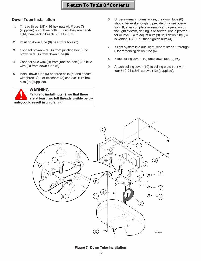
Down Tube Installation
1. Thread three 3/8" x 16 hex nuts (4, Figure 7)(supplied) onto three bolts (5) until they are hand-tight; then back off each nut 1 full turn.
2. Position down tube (6) near wire hole (7).
3. Connect brown wire (A) from junction box (3) tobrown wire (A) from down tube (6).
4. Connect blue wire (B) from junction box (3) to bluewire (B) from down tube (6).
5. Install down tube (6) on three bolts (5) and securewith three 3/8" lockwashers (8) and 3/8" x 16 hexnuts (9) (supplied).
WARNINGFailure to install nuts (9) so that thereare at least two full threads visible below
nuts, could result in unit falling.
6. Under normal circumstances, the down tube (6)should be level enough to provide drift-free opera-tion. If, after complete assembly and operation ofthe light system, drifting is observed, use a protrac-tor or level (C) to adjust nuts (9) until down tube (6)is vertical (+/- 0.5o); then tighten nuts (4).
7. If light system is a dual light, repeat steps 1 through6 for remaining down tube (6).
8. Slide ceiling cover (10) onto down tube(s) (6).
9. Attach ceiling cover (10) to ceiling plate (11) withfour #10-24 x 3/4" screws (12) (supplied).
Figure 7. Down Tube Installation
13
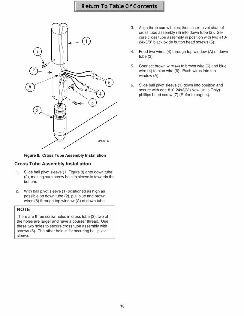
3. Align three screw holes; then insert pivot shaft ofcross tube assembly (3) into down tube (2). Se-cure cross tube assembly in position with two #10-24x3/8" black oxide button head screws (5).
4. Feed two wires (4) through top window (A) of downtube (2).
5. Connect brown wire (4) to brown wire (6) and bluewire (4) to blue wire (6). Push wires into topwindow (A).
6. Slide ball pivot sleeve (1) down into position andsecure with one #10-24x3/8" (New Units Only)phillips head screw (7) (Refer to page 4).
Cross Tube Assembly Installation
1. Slide ball pivot sleeve (1, Figure 8) onto down tube(2), making sure screw hole in sleeve is towards thebottom.
2. With ball pivot sleeve (1) positioned as high aspossible on down tube (2), pull blue and brownwires (6) through top window (A) of down tube.
NOTEThere are three screw holes in cross tube (3); two ofthe holes are larger and have a courser thread. Usethese two holes to secure cross tube assembly withscrews (5). The other hole is for securing ball pivotsleeve.
Figure 8. Cross Tube Assembly Installation
14
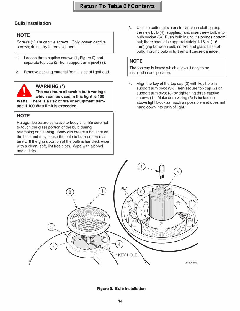
3. Using a cotton glove or similar clean cloth, graspthe new bulb (4) (supplied) and insert new bulb intobulb socket (5). Push bulb in until its prongs bottomout; there should be approximately 1/16 in. (1.6mm) gap between bulb socket and glass base ofbulb. Forcing bulb in further will cause damage.
NOTEThe top cap is keyed which allows it only to beinstalled in one position.
4. Align the key of the top cap (2) with key hole insupport arm pivot (3). Then secure top cap (2) onsupport arm pivot (3) by tightening three captivescrews (1). Make sure wiring (6) is tucked upabove light block as much as possible and does nothang down into path of light.
Figure 9. Bulb Installation
Bulb Installation
NOTEScrews (1) are captive screws. Only loosen captivescrews; do not try to remove them.
1. Loosen three captive screws (1, Figure 9) andseparate top cap (2) from support arm pivot (3).
2. Remove packing material from inside of lighthead.
WARNING (*)The maximum allowable bulb wattagewhich can be used in this light is 100
Watts. There is a risk of fire or equipment dam-age if 100 Watt limit is exceeded.
NOTEHalogen bulbs are sensitive to body oils. Be sure notto touch the glass portion of the bulb duringrelamping or cleaning. Body oils create a hot spot onthe bulb and may cause the bulb to burn out prema-turely. If the glass portion of the bulb is handled, wipewith a clean, soft, lint free cloth. Wipe with alcoholand pat dry.
MA326400
*2 1
3
45
6 4
KEY
KEY HOLE
15
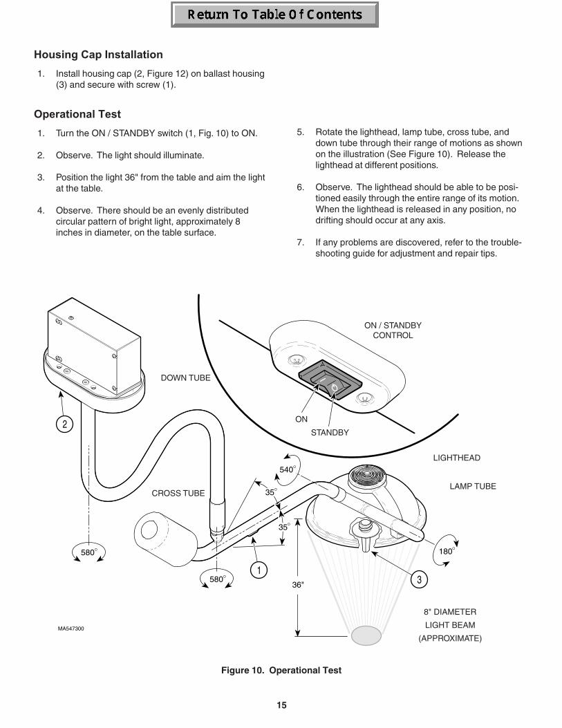
Housing Cap Installation
1. Install housing cap (2, Figure 12) on ballast housing(3) and secure with screw (1).
Operational Test
1. Turn the ON / STANDBY switch (1, Fig. 10) to ON.
2. Observe. The light should illuminate.
3. Position the light 36" from the table and aim the lightat the table.
4. Observe. There should be an evenly distributedcircular pattern of bright light, approximately 8inches in diameter, on the table surface.
1
MA547300
580
580
540
180
35
35
36"
2
3
ON
STANDBY
ON / STANDBYCONTROL
LIGHTHEAD
LAMP TUBE
8" DIAMETER
LIGHT BEAM
(APPROXIMATE)
DOWN TUBE
CROSS TUBE
5. Rotate the lighthead, lamp tube, cross tube, anddown tube through their range of motions as shownon the illustration (See Figure 10). Release thelighthead at different positions.
6. Observe. The lighthead should be able to be posi-tioned easily through the entire range of its motion.When the lighthead is released in any position, nodrifting should occur at any axis.
7. If any problems are discovered, refer to the trouble-shooting guide for adjustment and repair tips.
Figure 10. Operational Test
16
PROBLEM
no light from lighthead
no light from lighthead; on / standby switchis on
no light from lighthead although the bulband fuse were checked; lighthead flashesintermittently when lighthead or arms aremoved
down tube does not rotate freely or driftswhen released in desired position
lamp tube does not rotate freely or driftswhen released in desired position
cross tube rotates (at ball pivot joint) toostiffly or drifts when released in desiredposition
lighthead does not rotate freely at lamp tubeor drifts when released in desired position
POSSIBLE CAUSE
lighthead is off
bulb has burned out orhas not been installed
fuse in junction box isblown
no power to the junctionbox
transformer is malfunc-tioning
circuit or wiring problemwithin arm assemblies,junction box, or other partof lighting system
improper installation ofceiling plate (deflects toomuch or is not level)
brake tension needsadjusted
ball pivot joint tensionneeds to be adjusted orcross tube counterbal-ance needs adjusted
brake needs adjustment
SOLUTION
turn on / standby switch to on
refer to bulb installation proce-dure in this manual
inspect/replace the fuse locatedinside the ceiling cover
check for facility power to thejunction box
check for 24.5 VAC output fromtransformer (when loaded).
check all wiring connections. Ifproblem persists, call MidmarkTechnical Support: 1-800-Midmark
check for excessive flexing ofceiling support structure and/orcheck if ceiling plate is level.Readjust as necessary.
Call Midmark Technical Support:1-800-Midmark
refer to ball pivot joint tensionadjustment procedure in thismanual. If proper tension cannotbe achieved, refer to the crosstube counterbalance adjustmentprocedure in this manual andthen repeat main pivot jointtension adjustment. If problemstill persists, call MidmarkTechnical Support: 1-800-Midmark
Call Midmark Technical Support:1-800-Midmark
TABLE 1. TROUBLESHOOTING GUIDE
TROUBLESHOOTING
Troubleshooting Guide
If any problems are discovered during the installationprocess, refer to the following table (Table 1) to determinethe cause of the problem.
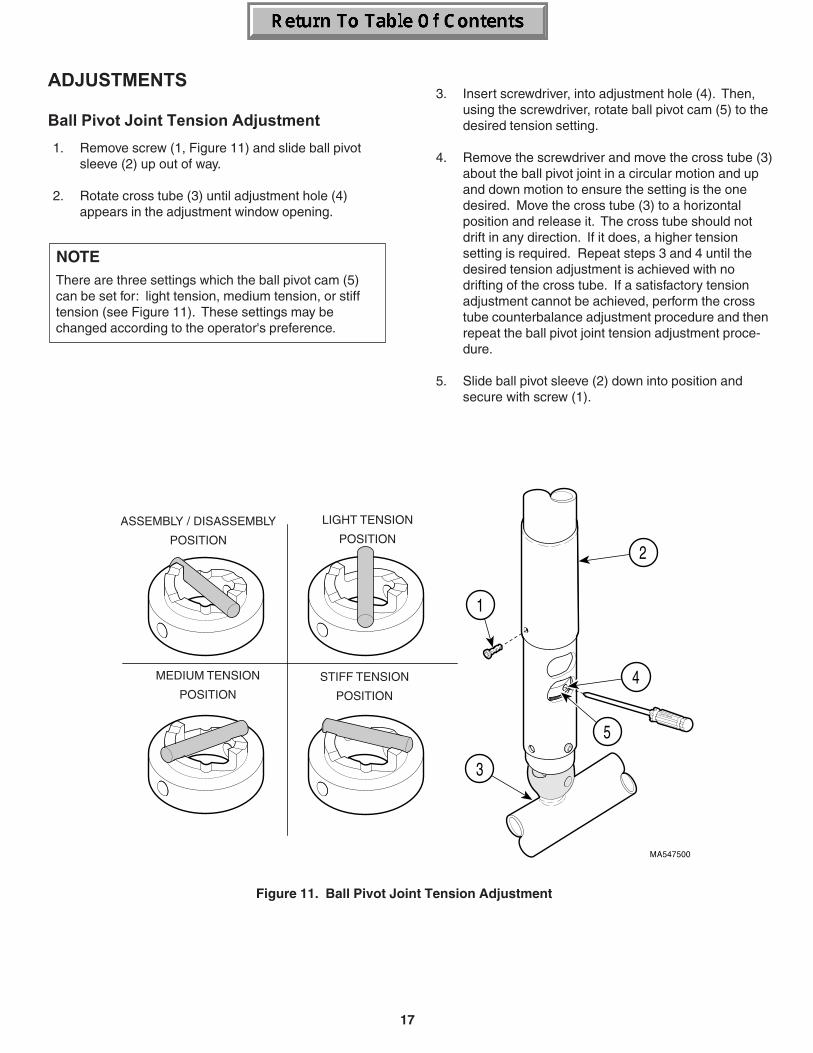
17
ADJUSTMENTS
Ball Pivot Joint Tension Adjustment
1. Remove screw (1, Figure 11) and slide ball pivotsleeve (2) up out of way.
2. Rotate cross tube (3) until adjustment hole (4)appears in the adjustment window opening.
NOTEThere are three settings which the ball pivot cam (5)can be set for: light tension, medium tension, or stifftension (see Figure 11). These settings may bechanged according to the operator's preference.
Figure 11. Ball Pivot Joint Tension Adjustment
3. Insert screwdriver, into adjustment hole (4). Then,using the screwdriver, rotate ball pivot cam (5) to thedesired tension setting.
4. Remove the screwdriver and move the cross tube (3)about the ball pivot joint in a circular motion and upand down motion to ensure the setting is the onedesired. Move the cross tube (3) to a horizontalposition and release it. The cross tube should notdrift in any direction. If it does, a higher tensionsetting is required. Repeat steps 3 and 4 until thedesired tension adjustment is achieved with nodrifting of the cross tube. If a satisfactory tensionadjustment cannot be achieved, perform the crosstube counterbalance adjustment procedure and thenrepeat the ball pivot joint tension adjustment proce-dure.
5. Slide ball pivot sleeve (2) down into position andsecure with screw (1).
ASSEMBLY / DISASSEMBLY
POSITION
LIGHT TENSION
POSITION
MEDIUM TENSION
POSITION
STIFF TENSION
POSITION
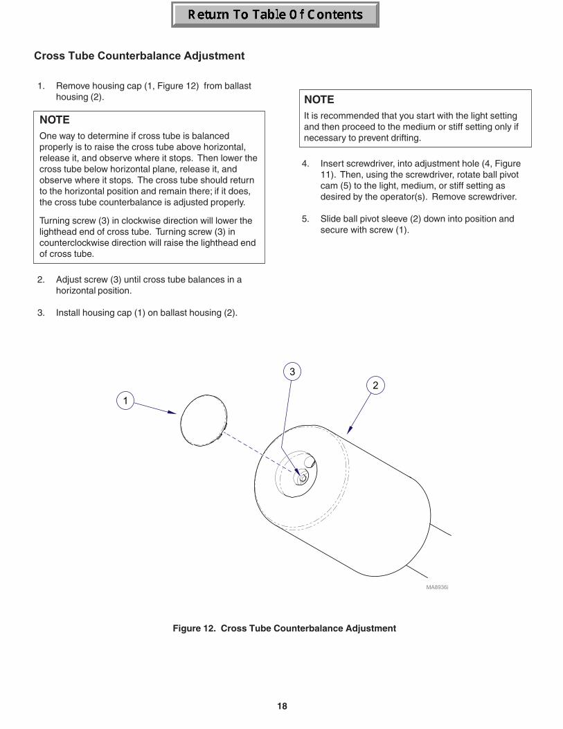
18
NOTEIt is recommended that you start with the light settingand then proceed to the medium or stiff setting only ifnecessary to prevent drifting.
4. Insert screwdriver, into adjustment hole (4, Figure11). Then, using the screwdriver, rotate ball pivotcam (5) to the light, medium, or stiff setting asdesired by the operator(s). Remove screwdriver.
5. Slide ball pivot sleeve (2) down into position andsecure with screw (1).
Cross Tube Counterbalance Adjustment
1. Remove housing cap (1, Figure 12) from ballasthousing (2).
NOTEOne way to determine if cross tube is balancedproperly is to raise the cross tube above horizontal,release it, and observe where it stops. Then lower thecross tube below horizontal plane, release it, andobserve where it stops. The cross tube should returnto the horizontal position and remain there; if it does,the cross tube counterbalance is adjusted properly.
Turning screw (3) in clockwise direction will lower thelighthead end of cross tube. Turning screw (3) incounterclockwise direction will raise the lighthead endof cross tube.
2. Adjust screw (3) until cross tube balances in ahorizontal position.
3. Install housing cap (1) on ballast housing (2).
Figure 12. Cross Tube Counterbalance Adjustment
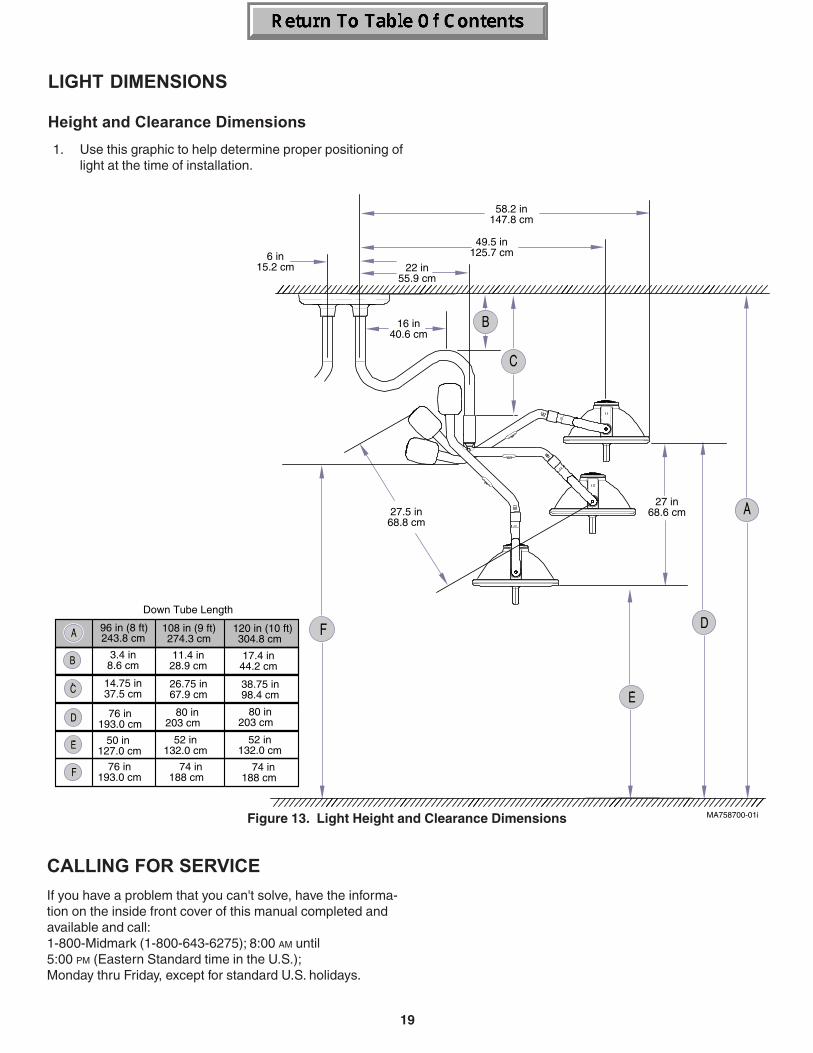
19
6 in15.2 cm
58.2 in147.8 cm
49.5 in125.7 cm
22 in55.9 cm
27.5 in68.8 cm
27 in68.6 cm
16 in40.6 cm
Down Tube Length
3.4 in8.6 cm
11.4 in28.9 cm
76 in 193.0 cm
50 in 127.0 cm
80 in 203 cm
52 in 132.0 cm
76 in 193.0 cm
74 in 188 cm
14.75 in37.5 cm
26.75 in67.9 cm
96 in (8 ft)243.8 cm
108 in (9 ft)274.3 cm
120 in (10 ft)304.8 cm
17.4 in44.2 cm
38.75 in98.4 cm
80 in 203 cm
52 in 132.0 cm
74 in 188 cm
MA758700-01iFigure 13. Light Height and Clearance Dimensions
CALLING FOR SERVICE
If you have a problem that you can't solve, have the informa-tion on the inside front cover of this manual completed andavailable and call:1-800-Midmark (1-800-643-6275); 8:00 AM until5:00 PM (Eastern Standard time in the U.S.);Monday thru Friday, except for standard U.S. holidays.
LIGHT DIMENSIONS
Height and Clearance Dimensions
1. Use this graphic to help determine proper positioning oflight at the time of installation.
20
SF-1490 REV. A1
SCOPE OF WARRANTYMidmark Corporation (“Midmark”) warrants to the original purchaser its new Alternate Care products and components(except for components not warranted under “Exclusions”) manufactured by Midmark to be free from defects in materialand workmanship under normal use and service. Midmark’s obligation under this warranty is limited to the repair orreplacement, at Midmark’s option, of the parts or the products the defects of which are reported to Midmark within theapplicable warranty period and which, upon examination by Midmark, prove to be defective.
APPLICABLE WARRANTY PERIODThe applicable warranty period, measured from the date of delivery to the original user, shall be one (1) year for allwarranted products and components.
EXCLUSIONSThis warranty does not cover and Midmark shall not be liable for the following: (1) repairs and replacements because ofmisuse, abuse, negligence, alteration, accident, freight damage, or tampering; (2) products which are not installed, used,and properly cleaned as required in the Midmark “Installation” and or “Installation / Operation Manual for this applicableproduct. (3) products considered to be of a consumable nature; (4) accessories or parts not manufactured by Midmark; (5)charges by anyone for adjustments, repairs, replacement parts, installation, or other work performed upon or in connectionwith such products which is not expressly authorized in writing in advance by Midmark.
EXCLUSIVE REMEDYMidmark’s only obligation under this warranty is the repair or replacement of defective parts. Midmark shall not be liablefor any direct, special, indirect, incidental, exemplary, or consequential damages or delay, including, but not limited to,damages for loss of profits or loss of use.
NO AUTHORIZATIONNo person or firm is authorized to create for Midmark any other obligation or liability in connection with the products.
THIS WARRANTY IS MIDMARK’S ONLY WARRANTY AND IS IN LIEU OF ALL OTHER WARRANTIES, EXPRESS ORIMPLIED. MIDMARK MAKES NO IMPLIED WARRANTIES OF ANY KIND INCLUDING ANY WARRANTIES OF MER-CHANTABILITY OR FITNESS FOR ANY PARTICULAR PURPOSE. THIS WARRANTY IS LIMITED TO THE REPAIR ORREPLACEMENT OF DEFECTIVE PARTS.
LIMITED WARRANTY


Midmark Corporation 60 Vista Drive Versailles, OH 45380 USA 1-800-643-6275 1-937-526-3662 www.midmark.com
003-1065-00 Rev. P (1/30/14)© Midmark Corporation - 1999


![NERCTranslate this page 2012 Policy Input.pdf%PDF-1.6 %âãÏÓ 355 0 obj > endobj 380 0 obj >/Filter/FlateDecode/ID[4FF2153BC892624397CB42C816EDD2EE>]/Index[355 776]/Info 354 0 R/Length](https://img.pdfslide.net/doc/110x75/5aceb9877f8b9a6c6c8c33f9/nerctranslate-this-2012-policy-inputpdfpdf-16-355-0-obj-endobj-380-0-obj-filterflatedecodeid4ff2153bc892624397cb42c816edd2eeindex355.jpg)