Embed Size (px)
Citation preview
EVALUATION OF RING LASER AND
FIBER OPTIC GYROSCOPE TECHNOLOGY
Jeng-Nan Juang R. Radharamanan
Mail to: [email protected]; [email protected]
School of Engineering, Mercer University, Macon, GA 31207 USA
Abstract
In past years much interest has been shown in the development of optical gyroscopes
which offer the potential of solid state, highly reliable performance immune from many
of the mechanical effects which restrict the performance of conventional spinning mass
gyroscopes. Both ring laser and fiber optic gyros operate by sensing the difference in
propagation time between beams of light traveling in clockwise and counter-clockwise
directions about some closed optical path [1]. This paper presents a brief overview of
optical gyroscopes and examines their suitability to a particular application where the current mechanical device has exhibited poor reliability. Conclusions are formulated that
support the recommendation of developing an open loop, analog fiber optic gyroscope
which will satisfy the requirements of the particular application of interest as well as
those of similar systems.
With the advent of laser technology in the 1960’s, a concentrated effort began to replace
rotating mass gyros with devices utilizing circulating light. This effort resulted in the
development of laser gyroscopes for certain high performance applications such as
aircraft navigation. More recently, a parallel effort has emerged to develop fiber optics
gyroscopes which can potentially be smaller, more rugged, and less costly than laser
gyros.
Key words: Rotating mass gyros, fiber optic gyroscope, ring laser, laser gyros, open
loop, circulating light.
Introduction
Historically, rate sensing requirements have been satisfied by conventional spinning mass
gyroscopes whose operation depends on the angular momentum generated by a rotating wheel or
ball. While modern gyroscopes are highly developed, sophisticated instruments, they are
inherently sensitive to environmental conditions and are limited by a variety of mechanical
effects.
The AN/AAS-35, Pave Panny system is a laser targeting system which incorporates a gimbal
assembly to mount and position optical receiver components. The gimbal assembly contains two
identical, single axis mechanical gyros. Pave Penny requirements are not particularly demanding
from the perspective of gyroscope performance, but are extremely rigorous environmentally. The
combination of relatively low performance specifications and harsh environment indicates that
an optical gyro may be preferred over the current mechanical device.

The goal of this paper is to present the findings and recommendations developed during a
feasibility study of upgrading the technology found in the AN/AAS-35, Pave Penny rate
gyroscope.
Optical Gyroscope Technology
Ring laser and fiber optical gyros both operate by sensing the difference in propagation time
between beams of light traveling in clockwise and counter-clockwise directions about some
closed optical path. A rotationally induced variance in path length produces a phase difference
between the light beams propagating in opposing directions. This difference is generally known
as the Sagnac effect and forms the basic operating principle of all optical gyroscopes [2].
The techniques used to measure the Sagnac effect in ring laser devices are vastly different than
those employed in fiber optic sensing. These differences serve as the distinction between the two
classes of devices and determine their size, weight, power requirements, performance, and cost
[3].
As illustrated in Figure 1, there are various classes of ring laser and fiber optic gyroscopes. Ring
laser gyros are distinguished by the method employed to overcome or reduce the lock-in effects
which occur at low rotational rates. Look-in is eliminated either by the introduction of a
mechanical dither, magneto-optic biasing, or by the use of multiple optic frequencies. Fiber optic
gyros are categorized by the techniques employed to measure the rotationally induced Sagnac
effect. Interferometric fiber optic gyros (IFOG) use fringe pattern examination to sense the
Sagnac effects while resonator fiber optic gyros (RFOG) employ resonant fiber cavities to do so.
Figure 1. Optical gyroscopes [2]
Basic Theory of Ring Laser Gyros
Ring Laser Gyroscopes (RLG) combines the functions of optical frequency generation and
rotation sensing into a laser oscillator within a ring shaped cavity. Typically, as in Figure 2, ring
laser gyros consist of a solid block, either square of triangular, of glass ceramic material into

which a lasing medium is introduced. The electrodes provide gain for the lasing medium,
generally a helium/neon mixture due to its short coherent length and index of refraction of nearly
1.0, which generates two independent beams direction in opposite directions around the cavity.
In order for the optical path to support lasing, there must be an integral number of wavelengths
around the path and oscillation will occur at that frequency, f which meets this requirement.
The cavity size is adjusted to support oscillation at frequencies optimal to the lasing media [4, 5].
This differential in frequency between the two traveling waves, the beat frequency f , is
described in the following relationship:
P
A
sf
4 (1)
Where A is the area and p the perimeter of the ring cavity, s is the wavelength of the light in
the lasing medium and is the angular rate of rotation.
Figure 2. Typical ring laser gyro [4]
Here, the ratio P
A
s
4 is known as the scale factor, K, of the gyro and f is directly proportional
to the rate of rotation .
The output of the ring laser gyroscope is typically developed by the use of a combining prism
which produces two nearly collinear beams interfering to create fringe patterns sensed by the
photo detectors [6]. The number of beats during a time interval is directly proportional to the
rotation rate and the direction of fringe movement is indicative of rotational direction. In

practice, the ring laser gyro is often operated in an integrating mode where each cycle of the beat
frequency is counted as one unit of angular displacement.
Limitations of Ring Laser Gyros
The ring laser gyroscope today is well established in the medium and high performance markets.
It offers many advantages over mechanical gyros; digital output linear with angular rotation, high
sensitivity and stability, quick reaction times, insensitivity to acceleration and immunity to most
environmental effects [7]. In spite of these advantages, the RLG remains a specialized instrument
whose utility varies with the application and several factors limit its selection over modern
mechanical system. The exacting cavity geometries and precision mirrors required for RLG
construction and the necessity of assembly under stringent clean room conditions drive its cost
beyond economic application to low performance system.
The size and weight of the RLG are other limiting factors to its use. The solid glass optical block
and mechanical dither assembly found in most RLGs unavoidably add to their weight [8].
Attempts to miniaturize the RLG have been met with a corresponding decrease in their
reliability. While large ring laser gyroscopes have demonstrated over 10,000 hours of operation,
smaller units (a few cm diameters) are limited to a few hundred hours of use. Additionally slow
leakage of the gas media, insignificant in large systems, may lead to shelf life problems in
smaller RLGs.
The power requirements of RLGs are high. To support the lasing action on which RLGs depend,
power sources capable of delivering several hundred volts, at low current, are required. Typical
RLG power requirements are five to ten watts [9].
Basic Theory of Fiber Optic Gyros
There are currently two main classes of fiber optic gyres under development, the interferometric
fiber optic gyro (IFOG) and the resonant fiber optic gyro (RFOG). The latter of these, the RFOG,
has received less attention to date and, though it appears to offer better potential accuracy, is the
less mature technology [10]. RFOG devices closely resemble ring laser gyros. They require a
narrowband light source and rely on an optical cavity. The cavity is formed from optical fiber
tuned so that only one frequency of light will propagate. Applied rotations change the
wavelength and hence the frequency of the light which will propagate. The basic configuration is
illustrated in Figure 3.
Figure 3. Resonant fiber optic gyro [10]

The fiber resonator is formed from a few coils of fiber and beam splitter. Two input ports
accommodate the CW and CCW beams which are generally produced from the same coherent
light source. In the absence of rotation, the two contra-rotating beams experience the same
transfer function through the coil. When a rotation is applied, the optical path for one beam
becomes slightly longer while that of the opposing beam becomes shorter producing Sagnac
frequency shifts.
As in RLGs, the resonant fiber optic gyro senses the beat frequency:
c c wcw fff (2)
Unlike the ring laser gyro, RFOGs do not contain a lasing media within the resonator and
therefore no direct measurement of f is possible; it must be measured by some means outside
the resonant cavity. This is typically accomplished by the use of frequency shifting devices such
as acousto-optic modulators (AOM) which track the beam frequencies, cwf and ccwf . The output
is then developed by deriving the difference frequency as depicted in Figure 3.
A typical IFOG device is shown in Figure 4. The IFOG uses a low coherence, super-radiant
diode as the light source and the polarizer, couplers, and sensing coil are generally fabricated
from polarization maintaining fiber [11]. The phase modulator is a piezoelectric fiber stretcher
consisting of a few turns of fiber wrapped around a piezoelectric transducer (PZT) cylinder.
Figure 4. Interferometric fiber optic gyroscope [11]
Limitations of Fiber Optic Gyroscopes
Resonant fiber optic gyros, RFOGs, rely on key components (coherent light source, extremely
low loss couplers, and frequency shifters) that are not readily available commercially and would
likely not withstand harsh field environments. Backscattering caused by the optical components
and the fiber itself tend to introduce undesirable nonlinear effects in FOG devices. This problem
is readily overcome by using broadband light sources whose short coherent length reduces
parasitic portions of backscattered waves. Fiber cable experiences time dependent fluctuations in
reciprocosity due to stress, vibration, temperature or exposure to magnetic fields. This source of
nonlinearity in FOGs is reduced by isolating the sensing coil from these disturbances and by
special coil winding techniques and careful thermal design. In spite of these difficulties, FOGs
have emerged as viable rate sensors for the low to medium performance ranges. For many
applications, FOGs offer a solid state, low cost, highly reliable, lightweight alternative requiring
low power, and no warm up time. Additionally, FOGs are capable of great flexibility in
geometry and packaging [12].
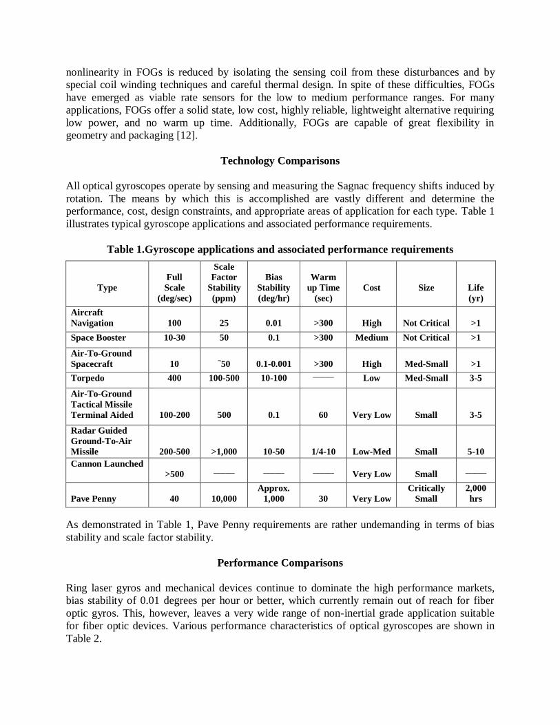
Technology Comparisons
All optical gyroscopes operate by sensing and measuring the Sagnac frequency shifts induced by
rotation. The means by which this is accomplished are vastly different and determine the
performance, cost, design constraints, and appropriate areas of application for each type. Table 1
illustrates typical gyroscope applications and associated performance requirements.
Table 1.Gyroscope applications and associated performance requirements
Type
Full
Scale
(deg/sec)
Scale
Factor
Stability
(ppm)
Bias
Stability
(deg/hr)
Warm
up Time
(sec)
Cost
Size
Life
(yr)
Aircraft
Navigation
100
25
0.01
>300
High
Not Critical
>1
Space Booster 10-30 50 0.1 >300 Medium Not Critical >1
Air-To-Ground
Spacecraft
10
~50
0.1-0.001
>300
High
Med-Small
>1
Torpedo 400 100-500 10-100 _______
Low Med-Small 3-5
Air-To-Ground
Tactical Missile
Terminal Aided
100-200
500
0.1
60
Very Low
Small
3-5
Radar Guided
Ground-To-Air
Missile
200-500
>1,000
10-50
1/4-10
Low-Med
Small
5-10
Cannon Launched
>500
_______
_______
_______
Very Low
Small
_______
Pave Penny
40
10,000
Approx.
1,000
30
Very Low
Critically
Small
2,000
hrs
As demonstrated in Table 1, Pave Penny requirements are rather undemanding in terms of bias
stability and scale factor stability.
Performance Comparisons
Ring laser gyros and mechanical devices continue to dominate the high performance markets,
bias stability of 0.01 degrees per hour or better, which currently remain out of reach for fiber
optic gyros. This, however, leaves a very wide range of non-inertial grade application suitable
for fiber optic devices. Various performance characteristics of optical gyroscopes are shown in
Table 2.

Table 2. Performance characteristics of optic gyroscopes [9]
Fabrication and Packaging Comparisons
Ring laser gyros require exacting cavity geometries involving strict dimensional accuracy,
precision mirrors, and extensive alignment and focusing. Their fabrication requires submicron
machining and assembly under ultra-clean room conditions.
Fiber optic gyros are much less demanding in their fabrication techniques and much more
flexible in their design and packaging. Mass production of fiber components, primarily for the
telecommunications industry, has lead to a significant cost advantage over ring laser and
mechanical gyros in many applications. Table 3 summarizes some of the major characteristics of
mechanical and optical gyroscopes.

Table 3. Major characteristics of mechanical and optical gyroscopes
Conclusions
The application of an advanced technology rotation sensor to the AN/AAS-35 Pave Penny
system is feasible. The low gyro performance required can be met by either a ring laser or fiber
optic device. However, there are no existing products which can fulfill the requirement of a form,
fit, and function replacement. The development of a Pave Penny gyro would primarily be an
exercise in packaging. The requirement for a device meeting all form, fit, and function
requirements of the current mechanical device and the inability to impose system level
modifications of any kind heavily weight the decision in favor of a fiber optic device.
Both ring laser and fiber optic gyroscopes have exhibited the ability to perform under adverse
environmental conditions where mechanical devices would be hard pressed to operate. Both have
proven to be viable contenders to mechanical systems and continue to make inroads into what
were once exclusive domains of mechanical devices. While ring laser gyros exist with
performance specifications far in excess of Pave Penny requirements, their relatively high
voltage requirements and high cost render them inappropriate for Pave Penny and similar
applications. RLGs are sophisticated, expensive instruments developed for high end gyroscope
applications and their development has not been, and likely will never be, aimed at low end
applications such as Pave Penny. It can be concluded that:
1. Pave Panny requirements do not represent a challenge in terms of gyroscope performance.
Instead, they are an exercise in packaging and environmental hardening.
2. Both ring laser and fiber optic devices are available which easily meet Pave Penny
performance specifications, however, no products are currently available which comply with
the form, fit and function restrictions.
3. It is feasible to develop an optical gyro for Pave Penny and similar systems. The necessary
technologies have matured to the point where a solid state rate sensing gyroscope for such
applications is within reach.
4. The preferred device for Pave Penny application is a fiber optic gyroscope due to its simple
construction, lower cost, and greater packaging flexibility.
A low cost, solid state, fiber optic gyroscope which will meet Pave Penny requirements and, with
minor modifications, can be made to satisfy rate sensing requirements in many other systems,
across USAF and DOD inventories should be developed.
References
[1] Stedman, G. E., Ring-Laser Tests of Fundamental Physics and Geophysics, In Reports on Progress in Physics,
60 (6), 1997, pp. 615--688.
[2] Nuttall, J. D., Optical Gyroscopes, Electronics and Power, November/December 1987.
[3] Pavlath, G. A., Fiber-Optic Gyroscopes, IEEE Lasers and Electro-Optics Society (LEOS) Annual Meeting,
LEOS '94 Conference Proceedings, Volume 2, 31 Oct-3 Nov. 1994, pp. 237-238.
[4] Schreiber, K. U., Velikoseltsev, A., Rothacher, M., Klugel, T., Stedman, G. E., and Wiltshire, D. L., Direct
Measurement of Diurnal Polar Motion by Ring Laser Gyroscopes, In Journal of Geophysical Research, 109
(B6): 2004.
[5] Schreiber, K. U., Klugel, T., and Stedman, G. E., Earth Tide and Tilt Detection by a Ring Laser Gyroscope, In
J. Geophys. Res, 108, 2003, p. 2132.
[6] Kung, A., Budin, J., Thévenaz, L., and Robert, P. A., Rayleigh Fiber Optics Gyroscope, In: IEEE Photonics
Technology Letters, vol. 9, num. 7, 1997, p. 973-5.
[7] Tajmar, M., Plesescu, F., and Seifert, B., Anomalous Fiber Optic Gyroscope Signals Observed above Spinning
Rings at Low Temperature, (Submitted on 13 Jun 2008 (v1), last revised 25 Jun 2008 (this version, v2))
[8] Aronowitz, F., Headed in the Right Direction, Photonics Spectra, September 1988, pp. 135-140.
[9] Udd, E., Comparison of Ring Laser and Fiber Optic Gyro Technology, McDonnell Douglas Astronautics
Company, 1985.
[10] Kersey, A.D., Fiber Optic Gyroscope Technology, Optics News, November 1989, pp.12-19.
[11] Ferrar, C.M., Progress in Fiber Optic Gyro Development, ISA Transactions, Vol. 28, No. 2, 1989.
[12] Private Correspondence Advanced Optical Systems, Los Angeles, CA, 1990.