Embed Size (px)
Citation preview

INSTRUCTIONINSTRUCTIONMANUALMANUAL
JLRJLR-86008600NWZNWZ-16501650
GPS NAVIGATORGPS NAVIGATOR
ISO 9001, ISO 14001 Certified
MAR. 2019 Edition 1CODE No.7ZPNA4699
Not use the asbestos
For further information,contact:
URL Head office : http://www.jrc.co.jp/eng/
Marine Service Department
1-7-32 Tatsumi, Koto-ku, Tokyo 135-0053, Japan
: +81-50-3786-9201e-mailOne-call


i
Safety Cautions
Cautions for High Voltage High voltage of hundreds volts is used inside this equipment. Touching a component inside the unit is very dangerous. Any person other than specialized maintenance staffs should not maintain, inspect, or adjust the unit. High voltages on the order of tens of thousand volts are most likely to cause instant deaths from electrical shocks. At times, even voltages on the order of several hundred volts could lead to electrocution. To defend against electrical shock hazards, do not put your hand into the inside of apparatus. When you put in a hand unavoidably in case of urgent, it is strongly suggested to turn off the power switch and allow the capacitors, etc. to discharge with a wire having its one end positively grounded to remove residual charges. Before you put your hand into the inside of apparatus, make sure that internal parts are no longer charged. Extra protection is ensured by wearing dry cotton gloves at this time. Another important precaution to observe is to keep one hand in your pocket at a time, instead of using both hands at the same time. It is also important to select a secure footing to work on, as the secondary effects of electrical shock hazards can be more serious. In the event of electrical shocks, disinfect the burnt site completely and obtain medical care immediately.
Precautions for Rescue of Victim of Electric Shock
When a victim of electric shock is found, turn off the power source and ground the circuit immediately. If this is impossible, move the victim away from the unit as quick as possible without touching him or her with bare hands. He or she can safely be moved if an insulating material such as dry wood plate or cloth is used. It is necessary to perform first aid immediately. Breathing may stop if current flows through the respiration center of brain due to electric shock. If the electric shock is not large, breathing can be restored by artificial respiration. A victim of electric shock looks pale and his or her pulse may become very weak or stop, resulting in unconsciousness and rigidity at worst.

ii
● Emergency Measures ●
Method of First-Aid Treatment
Precautions for First-Aid Treatments
Apply artificial respiration to the person who collapsed, minimizing moving as much as
possible avoiding risks. Once started, artificial respiration should be continued rhythmically.
(1) Refrain from touching the patient carelessly as a result of the accident; the first-aider could suffer from electrical shocks by himself or herself.
(2) Turn off the power calmly and certainly, and move the patient apart from the cable gently. (3) Call or send for a physician or ambulance immediately, or ask someone to call doctor. (4) Lay the patient on the back, loosening the necktie, clothes, belts and so on. (5) (a) Feel the patient's pulse.
(b) Check the heartbeat by bringing your ear close to the patient's heart. (c) Check for respiration by bringing your face or the back of your hand to the patient's
face. (d) Check the size of patient's pupils.
(6) Opening the patient's mouth, remove artificial teeth, cigarettes, chewing gum, etc. if any. With the patient's mouth open, stretch the tongue and insert a towel or the like into the mouth to prevent the tongue from being withdrawn into the throat. (If the patient clenches the teeth so tight that the mouth won't open, use a screwdriver or the like to force the mouth open and then insert a towel or the like into the mouth.)
(7) Wipe off the mouth to prevent foaming mucus and saliva from accumulating.

iii
☆Treatment to Give When the Patient Has a Pulse Beating but Has Ceased to Breathe
∗ Performing mouth-to-mouth artificial respiration (1) Bend the patient's face backward until it is directed to look back. (A pillow may be placed
under the neck.) (2) Pull up the lower jaw to open up the airway. (To spread the airway) (3) Pinching the patient's nose, breathe deeply and blow your breath into the patient's mouth
strongly, with care to close it completely. Then, move your mouth away and take a deep breath, and blow into his or her mouth. Repeat blowing at 10 to 15 times a minute (always with the patient's nostrils closed).
(4) Continue artificial respiration until natural respiration is restored. (5) If the patient's mouth won't open easily, insert a pipe, such as one made of rubber or vinyl,
into either nostril. Then, take a deep breath and blow into the nostril through the pipe, with the other nostril and the mouth completely closed.
(6) The patient may stand up abruptly upon recovering consciousness. Keep the patient lying calmly, giving him or her coffee, tea or any other hot drink (but not alcoholic drink) to keep him or her warm.
Mouth-to-mouth artificial respiration with the patient's head lifted
①
(1) Lift the back part of the patient's head. Support the forehead with one of your hand and the neck with the other hand.→ [1]. Many patients will have their airways opened by lifting their head in this way to ease mouth-to-mouth artificial respiration.
②
(2) Closing the patient's mouth you’re your mouth, press your cheek against the patient's nose→ [2]. Alternatively, hold the patient's nose with your finger to prevent air leak → [3].
③
(3) Blowing air into the patient's lungs. Blow air into the patient's lungs until chest is seen to rise. The first 10 breaths must be blown as fast as possible.
Fig. 1 Mouth-to-mouth artificial respiration

iv
Flow of Cardiopulmonary Resuscitation (CPR)
A person is collapsing. - Secure the safety of the surrounding area. - Prevent secondary disasters.
Check for response. - Call while tapping the shoulder.
Breathing
Recovery position - Lay the injured or
ill person on his/her side and wait for the arrival of the emergency services.
Not responding
Ask for help. - Make an emergency call. - Ask to bring an AED.
Listen to the appeal of the injured or ill person and give the necessary first-aid
Responding
Not breathing
Give 2 rescue breaths; omissible Note(1)
Give CPR. - 30 chest compressions - Give 2 rescue breaths; omissible Note(1)
Note(1) Omission of rescue breathing: If there is a fear of infection because the injured or ill person has an intraoral injury, you are hesitant about giving mouth-to-mouthresuscitation, or preparing the mouthpiece forrescue breathing takes too long, omit rescue breathing and proceed to the next step.
Open the airway. - Check for breathing.
Arrival of an AED
- Turn on the power.
- Use the AED by following its voice prompts. Fitting of the electrode pads, etc.
Automatic electrocardiogram analysis - Do not touch the injured or ill
person.
Electric shock is needed.
Electric shock is not needed.
Delivery of electric shock
Resume CPR from chest compressions by following the voice prompts of the AED.
When the injured or ill person has been handed over to the emergency services or has started moaning or breathing normally, lay him/her on his/her side in a recovery position and wait for the arrival of emergency services.
When to stop CPR
A person is collapsing. - Secure the safety of the surrounding area. - Prevent secondary disasters.
The AED automatically analyzes the heart rhythm every 2 min.

v
Specific Procedures for Cardiopulmonary Resuscitation (CPR) 1. Check the scene for safety to prevent secondary disasters
a) Do not touch the injured or ill person in panic when an accident has occurred. (Doing so may cause electric shock to the first-aiders.)
b) Do not panic and be sure to turn off the power. Then, gently move the injured or ill person to a safe place away from the electrical circuit.
2. Check for responsiveness
a) Tap the shoulder of the injured or ill and shout in the ear saying, "Are you OK?"
b) If the person opens his/her eyes or there is some response or gesture, determine it as "responding." But, if there is no response or gesture, determine it as "not responding."
3. If responding
a) Give first-aid treatment.
4. If not responding
a) Ask for help loudly. Ask somebody to make an emergency call and bring an AED. • Somebody has collapsed. Please help. • Please call an ambulance. • Please bring an AED. • If there is nobody to help, call an ambulance yourself.
5. Open the airway a) Touch the forehead with one hand. Lift the chin with the two fingers of
the middle finger and forefinger of the other hand and push down on the forehead as you lift the jaw to bring the chin forward to open the airway. If neck injury is suspected, open the airway by lifting the lower jaw.
6. Check for breathing
a) After opening the airway, check quickly for breathing for no more than 10 seconds. Put your cheek down by the mouth and nose area of the injured or ill person, look at his/her chest and abdomen, and check the following three points. • Look to see if the chest and abdomen are rising and falling. • Listen for breathing. • Feel for breath against your cheek.
Are you OK?
Please call an ambulance.
Please bring an AED.

vi
b) If the injured or ill person is breathing, place him/her in the recovery
position and wait for the arrival of the emergency services. • Position the injured or ill person on his/her side, maintain a clear and
open airway by pushing the head backward while positioning their mouth downward. To maintain proper blood circulation, roll him/her gently to position them in the recovery position in the opposite direction every 30 minutes.
7. Give 2 rescue breaths (omissible)
a) If opening the airway does not cause the injured or ill person to begin to breathe normally, give rescue breaths.
b) If there is a fear of infection because the injured or ill person has an intraoral injury, you are hesitant about giving mouth-to-mouth resuscitation, or getting and preparing the mouthpiece for rescue breathing takes too long, omit rescue breathing and perform chest compressions.
c) When performing rescue breathing, it is recommended to use a mouthpiece for rescue breathing and other protective devices to prevent infections.
d) While maintaining an open airway, pinch the person's nose shut with your thumb and forefinger of the hand used to push down the forehead.
e) Open your mouth widely to completely cover the mouth of the injured or ill person so that no air will escape. Give rescue breathing twice in about 1 second and check if the chest rises.
8. Cardiopulmonary resuscitation (CPR) (combination of chest compressions and rescue breaths) a) Chest compressions
1) Position of chest compressions • Position the heel of one hand in the center of the chest, approximately
between the nipples, and place your other hand on top of the one that is in position.
Roll gently in the opposite direction every 30 minutes.
CPR mask
Mouthpiece for rescue breathing

vii
2) Perform chest compressions • Perform uninterrupted chest compressions of 30 at
the rate of about 100 times per minute. While locking your elbows positioning yourself vertically above your hands.
• With each compression, depress the chest wall to a depth of approximately 4 to 5 cm.
b) Combination of 30 chest compressions and 2 rescue breaths 1) After performing 30 chest compressions, give 2 rescue
breaths. If rescue breathing is omitted, perform only chest compressions.
2) Continuously perform the combination of 30 chest compressions and 2 rescue breaths without interruption.
3) If there are two or more first-aiders, alternate with each other approximately every two minutes (five cycles of compressions and ventilations at a ratio of 30:2) without interruption.
9. When to stop cardiopulmonary resuscitation (CPR)
a) When the injured or ill person has been handed over to the emergency services
b) When the injured or ill person has started moaning or breathing normally, lay him/her on his/her side in a recovery position and wait for the arrival of emergency services.
10. Arrival and preparation of an AED
a) Place the AED at an easy-to-use position. If there are multiple first-aiders, continue CPR until the AED becomes ready.
b) Turn on the power to the AED unit. Depending on the model of the AED, you may have to push the power on button, or the AED automatically turns on when you open the cover.
c) Follow the voice prompts of the AED.
30 times
Compress with these parts (the heels of both hands).
2 times
Turn on the power.

viii
11. Attach the electrode pads to the injured or ill person's bare chest a) Remove all clothing from the chest, abdomen, and arms. b) Open the package of electrode pads, peel the pads off and securely
place them on the chest of the injured or ill person, with the adhesive side facing the chest. If the pads are not securely attached to the chest, the AED may not function. Paste the pads exactly at the positions indicated on the pads, If the chest is wet with water, wipe dry with a dry towel and the like, and then paste the pads. If there is a pacemaker or implantable cardioverter defibrillator (ICD), paste the pads at least 3cm away from them. If a medical patch or plaster is present, peel it off and then paste the pads. If the injured or ill person's chest hair is thick, paste the pads on the chest hair once, peel them off to remove the chest hair, and then paste new pads.
c) Some AED models require to connect a connector by following voice prompts.
d) The electrode pads for small children should not be used for children over the age of 8 and for adults.
12. Electrocardiogram analysis
a) The AED automatically analyzes electrocardiograms. Follow the voice prompts of the AED and ensure that nobody is touching the injured or ill person while you are operating the AED.
b) On some AED models, you may need to push a button to analyze the heart rhythm.
13. Electric shock (defibrillation)
a) If the AED determines that electric shock is needed, the voice prompt saying, "Shock is needed" is issued and charging starts automatically.
b) When charging is completed, the voice prompt saying, "Press the shock button" is issued and the shock button flashes.
c) The first-aider must get away from the injured or ill person, make sure that no one is touching him/her, and then press the shock button.
d) When electric shock is delivered, the body of the injured or ill person may jerk.
14. Resume cardiopulmonary resuscitation (CPR).
Resume CPR consisting of 30 chest compressions and 2 rescue breaths by following the voice prompts of the AED.
Press the shock button.

ix
15. Automatic electrocardiogram analysis a) When 2 minutes have elapsed since you resumed cardiopulmonary resuscitation (CPR), the
AED automatically analyzes the electrocardiogram. b) If you suspended CPR by following voice prompts and AED voice prompt informs you that
shock is needed, give electric shock again by following the voice prompts. If AED voice prompt informs you that no shock is needed, immediately resume CPR.
16. When to stop CPR (Keep the electrode pads on.)
a) When the injured or ill person has been handed over to the emergency services b) When the injured or ill person has started moaning or breathing normally, lay him/her on his/her
side in a recovery position and wait for the arrival of emergency services.

x
Foreword Thank you for purchasing the JRC GPS Navigator JLR-8600. This equipment is a high-performance navigation equipment consisting of a GPS sensor and navigator, can retrieve the position data using the GPS sensor to display various navigation information on the display. ● Thoroughly read this instruction manual before operating the equipment. ● Keep this manual nearby the equipment to allow ready access to it if necessary. It may
provide valuable information on how to deal with a given situation that may arise during the operation.

xi
Before Commencing the Operation
Symbols Several symbols are used in this manual to ensure safety and proper operation of the equipment and to avoid possible human injury or property damage. These symbols and their meanings are shown below. Please read and understand these symbols before proceeding to read this manual.
WARNING Instructions shown with this symbol represent what can cause death or serious injury if not observed.
CAUTION Instructions shown with this symbol represent what may cause injury or property damage if not observed.
Examples of the Symbols
The symbols shown in the ∆ mark represent those that require attention (including potential dangers and warnings). A depiction of the type of caution is shown inside the symbol (the left symbol indicates a general caution).
The symbols shown in the mark represent actions which are prohibited. A depiction of the type of prohibited action is shown inside the symbol (the left symbol indicates that disassembly is prohibited).
The symbol indicates required actions. A depiction of the type of required action is shown inside the symbol (the left symbol indicates that the power plug must be disconnected from the outlet).

xii
Precautions Upon the Operation
WARNING
Do not disassemble or modify the equipment. Doing so may result in fire, electric shock, or equipment failure.
Do not allow the display to become wet. Doing so may result in fire, electric shock, or equipment failure.
Operate the equipment only at the indicated voltage. Failure to do so may result in fire, electric shock, or equipment failure.
Install this unit at least 1 m away from any magnetic compasses. Installation near a magnetic compass may result in interference with the magnetic compass, and may result in an accident.
Do not perform internal inspections or modifications of the equipment. Inspection or modification by unauthorized personnel may result in fire, electric shock, or equipment failure. Please consult with JRC or an affiliate to perform internal inspections or repair.
When disposing of the used lithium battery, place insulating tape over the battery terminals, or otherwise insulate the battery. Failure to do so may result in heating, explosion, or fire due to a shorted battery.
In case you find smoke, unusual odor or extreme high heat coming from the equipment, turn off the power and breaker immediately. After that, please contact your dealer or agency or each branch office / head office / local office. Keeping operation under such condition may cause fire or electric shock.

xiii
CAUTION
The navigation information including the position data needs to be judged by the user himself. This equipment is not designed to automatically make judgments on the position data.
Do not use the equipment in the environment other than those provided in the specification. Doing so may result in equipment failure, malfunction, or injury.
Do not install the display unit in the location where it may come in contact with water, oil, or chemicals. Doing so may result in equipment failure, malfunction, or injury.
Do not install the equipment in the place subject to vibration or shock. Doing so may result in the equipment falling or collapsing, resulting in equipment failure or injury.
Do not place any item on the top of the equipment. Doing so may result in equipment failure, malfunction, or injury.
Please consult with JRC or an affiliate to perform installation. Installation by unauthorized personnel may result in malfunction.
Use only the specified battery. Failure to do so may result in battery leakage or rupture, resulting in fire, injury, or equipment failure.
Do not use benzine, alcohol or thinner when caring this equipment. Doing so may result in removing the paint or changing of properties. Wipe off the grime lightly with a dry soft cloth. Wipe with the other than a dry soft cloth may result in equipment injury.
Use the indicated screws when installing the display unit to a stable wooden surface. Failure to do so may result in the display unit falling over, causing injury or property damage.
Use only the specified fuse. Failure to do so may result in fire or equipment failure.
Use only the specified battery. Failure to do so may result in equipment failure or malfunction. Do not use a sharp tip, when tapping the touch panel. Doing so may result in screen injury.

xiv
When connecting the cable attached to the equipment, do not bend it acutely, twist it, or impart excessive force. Doing so sometimes causes cracks or damage to the coating, resulting in fire or electrocution. Do not install the sensor where there is excessive vibration. Vibration may cause sensor failure. Do not paint the sensor. Doing so may result in reception problems.
Do not install the sensor where temperature exceeds 55 degrees Celsius and there is covered with exhaust gas from funnel. Doing so may result in equipment failure or malfunction.
Use a fitted cable, when connected to junction box. The junction box rubber gaskets (25 f Gland side) fit 10mm – 20mm cables.
Install the sensor where there are no obstacles, in order to ensure that GPS signals can be directly received from satellites without interference or reflection of signals from surrounding objects. Whenever possible, select a place with the following characteristics.
If it is difficult to find an ideal site, select a place temporarily and install the equipment. Conduct a test to make sure that the proper performance can be obtained and then fix the equipment in position. If it is installed at an improper place, reception accuracy may be impaired.
If occurs bad positioning of such as satellite can not be received, please execute the re-start of sensor. If not recover, please consult with JRC or an affiliate There are cases when time lags in the gps navigator and gps compass. This is not a malfunction due to the delay in the internal processing. There are cases when time lags in the main display unit and sub display unit. This is not a malfunction due to the delay in the internal processing.
1. An open space, which allows uniform reception of satellite signals. 2. Far away from any high power transmission antennas. 3. Outside radar beams. 4. Away from the INMARSAT antenna by at least 5 meters and outside
the INMARSAT beam. 5. Away from the antenna of a VHF transmitter and a direction finder
by at least 3 meters. 6. Away from a Magnetic Compass by at least 1 meter. 7. Away from amateur radio antennas by at least 3 meters. Every time, Confirms the proper performance of equipment can be obtained, when changing the equipment location.
CAUTION

xv
Appearance of the Equipment ●NWZ-1650 Display Unit ●NDC-4100 Processor Unit ●JLR-4350 GPS Sensor Unit

xvi
Terminology
Term Meaning (Descriptions)
2D (2 dimension) Positioning with antenna elevation height in addition to satellite data.
3D (3 dimension) The three dimensional position fix, 4 or more satellites required.
Active route Route that is currently used by a ship
Anchor alert This alert monitors that the own ship is the preset distance or more away from the waypoint.
Arrival alert This alert informs that the own ship has traveled the preset distance, approaching the waypoint.
Beacon information Beacon data which is broadcast by message type 16.
BeiDou BeiDou is a satellite positioning system that is managed by China.
Boundary alert This alert informs that the own ship has got into the preset route.
CCRP Abbreviation of Consistent Common Reference Point. Reference position of the own ship.
CDI Abbreviation of Course Deviation Indicator. This indicator shows information on the deviation from the scheduled route and on the direction into which the ship should be steered.
Checksum An error detection method to check that the data has been correctly transmitted.
COG Course Over Ground.
Course Direction in which the ship is traveling, which is the bearing mainly displayed by the GPS.
CURRENT Sea and ocean currents, expressed in speed and direction.
Data route Ship route data that is stored in the memory of the equipment
Default gateway Equipment connected externally from a constructed network.
DGPS Abbreviation of Differential Global Positioning System. GPS satellite error data sent from a reference station whose position is accurately known is received via beacon from a beacon station, improving positioning accuracy.
FRAM Nonvolatile memory using a ferroelectric substance.
Geodetic Conditions for expressing position via latitude and longitude.
GPS Satellite (GPS) Abbreviation of Global Positioning System. Refers to satellites launched for navigational support of military vessels managed by the United States Department of Defense.
GLONASS GLONASS is a satellite positioning system that is managed by Russia.
HDOP Abbreviation of Horizontal Dilution of Precision. Indicates accuracy of positioning. The smaller the number, the higher the accuracy. If GPS satellites are unevenly distributed, this number will grow. If GPS satellites are evenly distributed, this number will be smaller.
IEC IEC is the abbreviation of International Electrotechnical Commission. It is an international standard governing electrical and electronic technologies.
IPXX IPXX is Degrees of protection provided by enclosures (IP Code) 1st numeral: Against ingress of solid foreign objects (0 – 6)

xvii
2nd numeral: Against ingress of water with harmful effects (0 - 8). (IPX4: splash-proof, IPX6: waterproof)
IP address ID number assigned to equipment on a constructed network.
LAN Abbreviation of Local Area Network. A network is constructed for transmitting and receiving data.
LCD Unit (LCD) Liquid Crystal Display Unit.
Leg Line between two consecutive waypoints.
Log Pulse Contact output signal, output in 1 pulse per nm. Expressed in units of "p/nm". mi/h Unit of ship speed.
Loran time difference
display Method for expressing the present position with loran system time difference. (The method is for operators who have a background in loran navigation.)
MAC address ID number assigned to LAN IC
Multi GNSS Positioning using multiple satellite systems at the same time.
Master reset This function changes the settings of the display unit and GPS sensor back to the factory settings. The function clears all the data. To perform the master reset, please consult with JRC or an affiliate
Multipath Wave Waves received from multiple directions due to reflection or refraction of an initial wave by obstacles.
Mutual monitoring mode When two navigators are installed, they monitor their position fixing status each other by using this function.
NMEA0183 (NMEA) Abbreviation of National Marine Electrical Association 0183. International standard for naval equipment transmission established by the National Marine Electrical Association.
QZSS QZSS is a Quasi-zenith satellite system that is managed by Japan and complements GPS.
Positioning Use of GPS or DGPS receiving functions to determine the current position of a ship.
RAIM Accuracy Standard (RAIM) Abbreviation of Receiver Autonomous Integrity Monitoring. This
system automatically detects failed satellites and deselects their positioning data from calculations. Including data from failed satellites will result in a decrease in positioning accuracy; the RAIM accuracy standard indicates the accuracy degradation base for removal of failed satellites from positioning calculations.
Ranging Positioning with the use of SBAS satellite in addition to GPS satellite.
Reception Level GPS signal reception level.
Route plan Plan registered with multiple waypoints in the navigation order
RS-232C Serial data transmission standard. It is unbalanced, and hence can only be used for short distance transmission.
RS-422 Balanced serial transmission standard.
SBAS Abbreviation of Satellite Based Augmentation System. It is a blanket term for wide scale GPS support systems using fixed position satellites which send GPS error correction data over a wide range.

xviii
SBAS Search SBAS reception mode (manual / automatic).
Shared route Function that uses the same route as other functions such as ECDIS do. The route can be updated automatically by sharing the active route.
Smoothing Function for averaging over a specified number of seconds.
SOG Speed Over Ground, This is the ship’s relative speed to the ground.
SPEED The speed mainly measured by the GPS.
STW Speed Through Water.
Subnet mask Value for identifying the network address
Symbol information Information of symbols displayed on the plotting screen. The information includes symbol positions, comments, etc.
TD Abbreviation of Time Difference. Time difference from the master-station signal of the loran system to the slave-station signal.
Message Type 0 SBAS satellite test broadcasting.
UTC Abbreviation of Coordinated Universal Time.
XTD alert This alert informs that the own ship has got out of the scheduled route by the preset distance or more.

xix
Contents ● Safety Cautions ● ............................................................................................................................... i ● Emergency Measures ● ..................................................................................................................... ii Foreword ............................................................................................................................................... x Before Commencing the Operation ..................................................................................................... xi Precautions Upon the Operation ........................................................................................................ xii Appearance of the Equipment ............................................................................................................ xv Terminology ........................................................................................................................................ xvi
Chapter 1 Equipment Overview ...................................................................................................... 1-1 1.1 Functions ............................................................................................................................... 1-1 1.2 Features ................................................................................................................................ 1-1 1.3 Configuration ......................................................................................................................... 1-2
1.3.1 Standard Configuration .................................................................................................. 1-2 1.3.2 Option ............................................................................................................................ 1-3
1.4 Construction .......................................................................................................................... 1-4 1.5 System Diagram .................................................................................................................. 1-13
Chapter 2 Name and Function of Each Unit ................................................................................... 2-1 2.1 NWZ-1650 DISPLAY UNIT .................................................................................................... 2-1 2.2 JLR-4350 GPS Sensor .......................................................................................................... 2-3 2.3 NDC-4100 Processor Unit ..................................................................................................... 2-3
Chapter 3 Display Screens ............................................................................................................. 3-1 3.1 Display Screens .................................................................................................................... 3-1
3.1.1 Switching display ........................................................................................................... 3-1 3.1.2 Navigation information screen ....................................................................................... 3-1 3.1.3 Plotting screen 1 ............................................................................................................ 3-5 3.1.4 Plotting screen 2 ............................................................................................................ 3-6 3.1.5 Analogue screen ............................................................................................................ 3-7 3.1.6 Highway screen ............................................................................................................. 3-8 3.1.7 Satellite information screen ........................................................................................... 3-8 3.1.8 Waypoint information screen ......................................................................................... 3-9 3.1.9 Beacon text screen ........................................................................................................ 3-9 3.1.10 Navigation aid screen .................................................................................................. 3-10
Chapter 4 Operation ....................................................................................................................... 4-1 4.1 Menu List ............................................................................................................................... 4-1
4.1.1 Main Menu ..................................................................................................................... 4-1 4.1.2 Function menu ............................................................................................................... 4-7
4.2 Basic Operation ..................................................................................................................... 4-8 4.2.1 Turning on the power of the unit .................................................................................... 4-8 4.2.2 Startup ........................................................................................................................... 4-8 4.2.3 Turning off the power of the unit .................................................................................... 4-9 4.2.4 Adjusting the backlight ................................................................................................. 4-10 4.2.5 Menu operation ............................................................................................................ 4-10 4.2.6 Alert and acknowledgment (ACK) ............................................................................... 4-11 4.2.7 Screen operation ......................................................................................................... 4-13 4.2.8 Inputting numeric values .............................................................................................. 4-13 4.2.9 Inputting comments ..................................................................................................... 4-14 4.2.10 List operation ............................................................................................................... 4-15 4.2.11 Entering a password in CODE INPUT ......................................................................... 4-15
4.3 Setting Display .................................................................................................................... 4-16 4.3.1 Setting a theme ............................................................................................................ 4-16 4.3.2 Setting a beep tone ...................................................................................................... 4-16 4.3.3 Setting reverse video display ....................................................................................... 4-16 4.3.4 Selecting a display screen ........................................................................................... 4-17
4.4 Registering Waypoints ........................................................................................................ 4-18 4.4.1 Displaying a waypoint list............................................................................................. 4-18 4.4.2 Registering waypoints .................................................................................................. 4-19 4.4.3 Editing waypoints ......................................................................................................... 4-22 4.4.4 Copying waypoints ....................................................................................................... 4-22 4.4.5 Deleting waypoints ....................................................................................................... 4-23
4.5 Route Plan ........................................................................................................................... 4-24

4.5.1 Displaying a route list ................................................................................................... 4-24 4.5.2 Creating routes ............................................................................................................ 4-25 4.5.3 Editing routes ............................................................................................................... 4-27 4.5.4 Copying routes ............................................................................................................. 4-28 4.5.5 Deleting routes ............................................................................................................. 4-29 4.5.6 Sharing a route with another piece of equipment ........................................................ 4-31 4.5.7 Setting route initial values ............................................................................................ 4-32
4.6 Executing a Route ............................................................................................................... 4-34 4.6.1 Executing a route by selecting from a route list ........................................................... 4-34 4.6.2 Selecting a waypoint/route by using the GOTO key .................................................... 4-35 4.6.3 Ending a route ............................................................................................................. 4-38
4.7 Event/Mark .......................................................................................................................... 4-39 4.7.1 Displaying an event/mark list ....................................................................................... 4-39 4.7.2 Registering events ....................................................................................................... 4-39 4.7.3 Registering marks ........................................................................................................ 4-40 4.7.4 Editing events/marks ................................................................................................... 4-41 4.7.5 Deleting events/marks ................................................................................................. 4-41
4.8 Plotting Screen .................................................................................................................... 4-43 4.8.1 Operating the cursor .................................................................................................... 4-43 4.8.2 Changing the cursor size ............................................................................................. 4-43 4.8.3 Moving a screen .......................................................................................................... 4-44 4.8.4 Moving own ship to the centre of the screen ............................................................... 4-44 4.8.5 Screen Zoom In/Out .................................................................................................... 4-45 4.8.6 Changing North Up/Course Up .................................................................................... 4-45 4.8.7 Displaying tracks .......................................................................................................... 4-46 4.8.8 Displaying an own ship vector and a distance circle ................................................... 4-47 4.8.9 Setting symbols to display/non-display ........................................................................ 4-48 4.8.10 Displaying symbol information ..................................................................................... 4-48 4.8.11 Changing a background colour .................................................................................... 4-49
4.9 Setting MOB ........................................................................................................................ 4-50 4.10 Setting Alerts ....................................................................................................................... 4-51
4.10.1 Setting alert/buzzer sounds for SOLAS ship ............................................................... 4-52 4.10.2 Setting alert/buzzer sounds for non-SOLAS ship ........................................................ 4-55
4.11 Alert List............................................................................................................................... 4-59 4.11.1 Displaying alert history ................................................................................................. 4-59 4.11.2 Displaying the alert that is occurring ............................................................................ 4-59 4.11.3 Displaying the alerts that occurred in LAN .................................................................. 4-60
4.12 Initial Settings of GNSS/Beacon/SBAS ............................................................................... 4-61 4.12.1 Setting a positioning system ........................................................................................ 4-61 4.12.2 Setting a position fixing mode ...................................................................................... 4-62 4.12.3 Setting an elevation mask............................................................................................ 4-62 4.12.4 Setting HDOP .............................................................................................................. 4-63 4.12.5 Setting position, speed, and course smoothing ........................................................... 4-63 4.12.6 Setting RAIM ................................................................................................................ 4-64 4.12.7 Setting a geodetic system............................................................................................ 4-64 4.12.8 Initialising sensors ....................................................................................................... 4-65 4.12.9 Setting a DGPS correction mode ................................................................................ 4-65 4.12.10 Setting a beacon ...................................................................................................... 4-67 4.12.11 Setting SBAS ........................................................................................................... 4-68 4.12.12 Displaying a beacon station list ............................................................................... 4-68
4.13 Configuring a System .......................................................................................................... 4-69 4.13.1 Setting time difference/date display ............................................................................. 4-69 4.13.2 Setting units ................................................................................................................. 4-69 4.13.3 Setting magnetic correction ......................................................................................... 4-70 4.13.4 Setting LORAN A/C ..................................................................................................... 4-70 4.13.5 Selecting a sensor ....................................................................................................... 4-71
4.14 Printing ................................................................................................................................ 4-72 4.15 Setting a Language ............................................................................................................. 4-72 4.16 Verifying Versions ................................................................................................................ 4-72 4.17 Displaying a total trip distance ............................................................................................ 4-73
4.17.1 Starting/stopping measurement of a trip distance ....................................................... 4-73 4.17.2 Resetting a trip distance .............................................................................................. 4-73 4.17.3 Resetting a total trip distance ...................................................................................... 4-73

4.18 Measuring a trip distance .................................................................................................... 4-74 4.18.1 Starting/stopping measurement ................................................................................... 4-74 4.18.2 Resetting a trip distance .............................................................................................. 4-74
4.19 Displaying external equipment information ......................................................................... 4-75 4.20 Measuring a distance and an azimuth between two points ................................................ 4-76
Chapter 5 Maintenance and Inspection .......................................................................................... 5-1 5.1 General Maintenance and Inspection ................................................................................... 5-1 5.2 Alerts ..................................................................................................................................... 5-2 5.3 Troubleshooting ..................................................................................................................... 5-5 5.4 Replacement Parts ................................................................................................................ 5-7
5.4.1 Repair units .................................................................................................................... 5-7 5.4.2 Regular replacement parts ............................................................................................ 5-7
Chapter 6 After-Sales Service ........................................................................................................ 6-1 6.1 Warranty ................................................................................................................................ 6-1 6.2 Repair parts stocking Period ................................................................................................. 6-1 6.3 When Requesting Service ..................................................................................................... 6-1 6.4 Recommended Checks Inspection ....................................................................................... 6-1
Chapter 7 Disposal ......................................................................................................................... 7-1 7.1 Disposal of Equipment .......................................................................................................... 7-1 7.2 Disposal of Used Batteries .................................................................................................... 7-1
Chapter 8 Specification .................................................................................................................. 8-1 8.1 NWZ-1650 DISPLAY UNIT ................................................................................................. 8-1
8.1.1 Basic .............................................................................................................................. 8-1 8.1.2 Environment ................................................................................................................... 8-1
8.2 JLR-4350 GPS Sensor .......................................................................................................... 8-2 8.2.1 Basic .............................................................................................................................. 8-2 8.2.2 Environment ................................................................................................................... 8-2
8.3 NDC-4100 Processor Unit ..................................................................................................... 8-3 8.3.1 Basic .............................................................................................................................. 8-3 8.3.2 Environment ................................................................................................................... 8-3 8.3.3 Interface ......................................................................................................................... 8-4
Appendix .................................................................................................................................................. 1 Appendix 1 List of Geodetic System ................................................................................................ 1 Appendix 2 List of standard terms, units and abbreviations ............................................................ 2 Appendix 3 List of Symbols .............................................................................................................. 7 Appendix 4 List of Default Setting Values ........................................................................................ 8 Appendix 5 Data Format ................................................................................................................ 13 Appendix 6 Compass Safe Distance ............................................................................................. 30 Appendix 7 About Chinese version RoHS ..................................................................................... 31

1-1
Chapter 1 Equipment Overview
1.1 Functions This equipment (JLR-8600) is a GPS navigator with a JLR-4350GPS sensor that is connected to the NWZ-1650 display unit and the NDC-4100 processing unit. JLR-4350, which is a multi-GNSS receiver that is capable of receiving data from GPS as well as GLONASS or BeiDou, operates around-the-clock to measure positions with high accuracy anywhere in the world and in all weather conditions by using the GPS satellite and the GLONASS satellite, or the BeiDou satellite, and produces highly reliable positioning results. In addition, the GPS navigator can increase the accuracy of position fixing by receiving correction data from the SBAS satellites.
1.2 Features Registration of up to 100 routes and 10000 waypoints Many output ports installed with the built-in buffer unit Enables sharing of a route with ECDIS by the mounted LAN High visibility 6.5-inchi large colour LCD Provided with many graphic display modes Mutual acknowledgment through a contact or ALR Improved operability by touch panel and abundant menus High reliability by the multi-GNSS receivers (GPS/GLONASS/BeiDou/QZSS/SBAS) Built-in RAIM function

1-2
1.3 Configuration
1.3.1 Standard Configuration JLR-8600 No Name Model Q'ty Note 1 GPS Sensor Unit JLR-4350 1 1-1 Screw Adapter MTV302007A 1 1-2 Mounting Band MPBP02520 1 Include 2 bands 1-3 Instruction manual 7ZPNA4693 1 English 1-4 Cable guard rubber MPPK31468 1 2 Processor Unit NDC-4100 1
2-1 Fuse MF51NR 250V 5 MF51NR 250V 2
1 MF51NR 250V 5 :4 Fuses MF51NR 250V 2 :1 Fuses
3 Display Unit NWZ-1650 1
3-1 Model Identification Plate
MPNN50903 1
3-2 Clamp Filter 5MBIR00009 1 3-3 Flush mount kit MPBX50891 1 4 Display cable CFQ-7540 1 LAN 15m for DISPLAY 5 Instruction manual 7ZPNA4699 1 7ZPNA4698(Japanese)/7ZPNA4699(English)
NWZ-1650 No Name Model Q'ty Note 1 Display Unit NWZ-1650 1 Refer to JLR-8600(3~3-3) 2 Instruction manual 7ZPNA4699 1 7ZPNA4698(Japanese)/7ZPNA4699(English)

1-3
1.3.2 Option No Name Model Q'ty Note
1 AC/DC Power supply unit
NBD-904 1 For InmarsatC AC100/220V, DC24V Input DC24V Output
2 Data Power Cable CFQ-7539 1 8 cores 15m / For Remote Display 3 Data power Cable CFQ-7539-5 1 8 cores 5m / For Remote Display 4 Printer NKG-104 1 5 Printer Paper 7ZPJD0384 1 For NKG-104 6 Extension Cable CFQ-9000 1 Dual end/6 cores/ 15m/For Sensor 7 Extension Cable CFQ-9002 1 Single end/6 cores/5 m 8 Junction Box NQE-7700A 1 6 terminals 9 Pole Mounting Kit MPBP30608 1 For NQE-7700A
10 Coaxial Cable Kit NQD-4414 1 Outdoor NQD-4410, Indoor NQD-4411
11 Select Switch NCZ-777 1
Manual N4 2.5G7/2 7.5BG7/2
12 Select Switch NCZ-1537B 1 Automatic 13 Junction Box CQD-10 1 16 terminals 14 Screw Adapter MTV302007A 1 For Sensor 15 Mounting Band MPBP02520 1 For Sensor 16 Output Buffer NQA-4351 1
17 Select Switch NCZ-1663 1
Manual 2.5G7/2 7.5BG7/2 N2.5
18 External Dimmer unit NCM-227 1 7.5BG7/2 2.5G7/2
19 Printer RP-D10 1 Network printer
20 Power supply NBG-980 Power supply unit for Network printer
21 Base kits MPBX50347 1

1-4
1.4 Construction NWZ-1650 Display Unit (Desktop mount)
NWZ-1650 Display Unit (Flush Mount)
Unit: mm Mass: Appoximately: 1kg Color: Munsell N2.5 IP Grade: IP56
Unit: mm Mass: Approximately 1.5kg Color: Munsell N2.5 IP Grade: IP56 Base kits is option.

1-5
NDC-4100 Processor Unit
JLR-4350 GPS Sensor Unit
Unit: mm Mass: Approximately 1.9kg Color: Munsell N2.5 IP Grade: IP22
Unit: mm Mass: Approximately 1.2kg (include 15m cable) Color: Munsell N9 IP Grade: IP56 (IEC60945)
Installation Screw 4-M5

1-6
NBD-904 AC/DC Power supply unit
NQE-7700A Junction Box
Unit: mm Mass: Approximately 0.6 kg
Unit: mm Mass:Approximately 2.6 kg
Gland 15
Gland 25
DGPS cable CFQ-8919
Cable diameter 5 - 11
Cable diameter 10 - 20
Serial Number Seal
Fuse x 2 Mounting Holes 4-dia6x8
Volume x 3

1-7
NQD-4414 Coaxial Cable Kit (outdoor use NQD-4410)
NQD-4414 Coaxial Cable Kit (indoor use NQD-4411)
Unit: mm Mass: Approximately 1.5 kg
Unit: mm Mass: Approximately 0.7 kg
(Installation Screw M3)
(Installation Screw M8)

1-8
NQA-4351 Output Buffer
Unit: mm Mass: Approximately 0.8 kg

1-9
NCZ-777 Select Switch (Stationary)
NCZ-777 Select Switch (Flush Mounting)
Unit: mm Mass: Approximately 0.5 kg
Unit: mm Mass: Approximately 0.7 kg
(Installation Screw M6)
(Installation Screw M6)

1-10
NCZ-1663 Select Switch (Stationary)
NCZ-1663 Select Switch (Flush Mounting)
Unit: mm Mass: Approximately 0.2 kg
Unit: mm Mass: Approximately 0.2 kg

1-11
NCZ-1537B Select Switch (Flush Mounting)
Unit: mm Mass: Approximately 0.55 kg

1-12
CQD-10 Junction Box
NKG-104 Printer
Unit: mm Mass: Approximately 1.1 kg
Unit: mm Mass: Approximately 2.1 kg
4-φ7.5 (Installation Screw M6)

1-13
1.5 System Diagram
JLR-4350 GPS Sensor
Sensor Display Unit
LAN
RS-422 NDC-4100 Processor Unit
Contact
RS-422 (Internal Buffer)
Power Supply
NBD-904 PowerSupply
Radar ECDIS/Plotter Tide Current Calculator Printer NKG-104
ECDIS Remote Maintenance MFD
Alarm System
NQE-7700A Junction Box
NWZ-1650 Display Unit
External equipment
DC12/24V
DC24V
AC110/220V
DC24V
※250V-MPYCYS-7 LAN CFQ-7540
※Ethernet×2
※250V-TTYCS-1 IN×2 OUT×5
※250V-TTYCS-1 IN×1 OUT×4
※250V-TTYCS-1 OUT×8
※0.6/1kV-DPYC-1.5
※Arranged by dockyard

1-14

2-1
Chapter 2 Name and Function of Each Unit
2.1 NWZ-1650 DISPLAY UNIT Touch panel
Key Name Function
Alert Displays the icon when an alert is issued. The icon changes according to the alert state.
MOB Displays a plotting screen and stores the Man OverBoard position.
DIM UP Increases the brightness.
DIM DOWN Reduces the brightness.
Menu Displays a menu. Displays a freeze indicator.
Screen Switches a main screen. Select from a main screen list.
Function Displays the operation menu on the main screen.
Screen switch
Switches to a sub screen.
Screen switch
Switches to a sub screen.
Buzzer
DISPLAY Displays the information of own ship and equipment setting screen. Operated by the touch panel.
Status area Displays the status of the equipment or system with the icon.
Power supply key
2-2
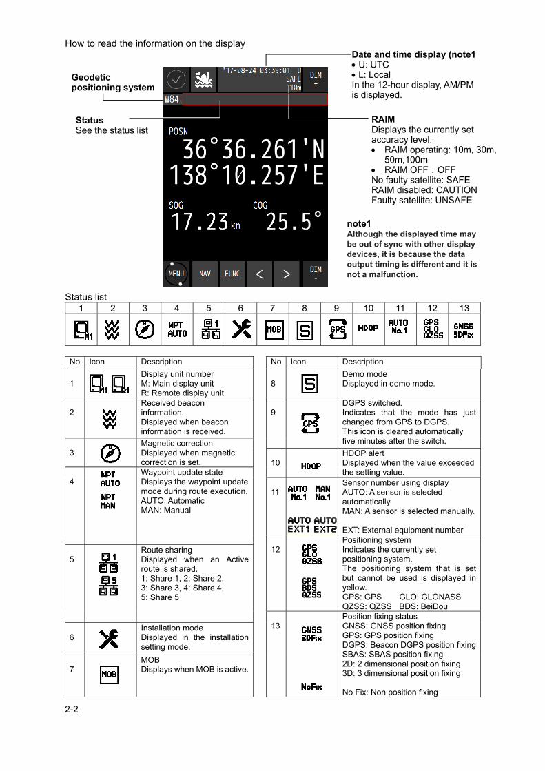
How to read the information on the display Status list
1 2 3 4 5 6 7 8 9 10 11 12 13
No Icon Description No Icon Description
1
Display unit number M: Main display unit R: Remote display unit
8
Demo mode Displayed in demo mode.
2
Received beacon information. Displayed when beacon information is received.
9
DGPS switched. Indicates that the mode has just changed from GPS to DGPS. This icon is cleared automatically five minutes after the switch.
3
Magnetic correction Displayed when magnetic correction is set.
10
HDOP alert Displayed when the value exceeded the setting value.
4
Waypoint update state Displays the waypoint update mode during route execution. AUTO: Automatic MAN: Manual
11
Sensor number using display AUTO: A sensor is selected automatically. MAN: A sensor is selected manually. EXT: External equipment number
12
Positioning system Indicates the currently set positioning system. The positioning system that is set but cannot be used is displayed in yellow. GPS: GPS GLO: GLONASS QZSS: QZSS BDS: BeiDou
5
Route sharing Displayed when an Active route is shared. 1: Share 1, 2: Share 2, 3: Share 3, 4: Share 4, 5: Share 5
13
Position fixing status GNSS: GNSS position fixing GPS: GPS position fixing DGPS: Beacon DGPS position fixing SBAS: SBAS position fixing 2D: 2 dimensional position fixing 3D: 3 dimensional position fixing No Fix: Non position fixing
6
Installation mode Displayed in the installation setting mode.
7
MOB Displays when MOB is active.
RAIM Displays the currently set accuracy level. RAIM operating: 10m, 30m,
50m,100m RAIM OFF:OFF No faulty satellite: SAFE RAIM disabled: CAUTION Faulty satellite: UNSAFE
Geodetic positioning system
Status See the status list
Date and time display (note1 U: UTC L: Local In the 12-hour display, AM/PM is displayed.
note1 Although the displayed time may be out of sync with other display devices, it is because the data output timing is different and it is not a malfunction.

2-3
2.2 JLR-4350 GPS Sensor
2.3 NDC-4100 Processor Unit
6 pins Connector Approx. φ19mm
Base
Data Cable 15m Approx. φ6mm
Mounting Screw 1 inch 14 UNS-2B
Mounting Screw hole
Cover
Cable Inlet
Earth terminal
Radome

2-4

3-1
Chapter 3 Display Screens
3.1 Display Screens
3.1.1 Switching display
When the screen key is tapped, a display screen list is displayed. Select a screen to be
displayed from the list. The screen name is displayed on the screen key. On the navigation information screen, the analogue screen, and the navigation support screen, a
sub screen can be displayed by using or .
3.1.2 Navigation information screen The navigation information screen displays the position, speed, and course of own ship. When a waypoint is available, the waypoint number and estimated time of arrival are also displayed.
A sub screen can be displayed by using or . The sub screen varies depending on the
presence or absence of the waypoint.
Display screen list
Own ship's position (latitude and longitude)
Speed Course

3-2
Sub screen a) If there are no waypoints
Own ship's position (latitude and longitude)
Own ship's position (latitude and longitude)
Speed
Speed Course
Course
Sub Screen 1 (4 digit position screen)
Sub Screen 2 (SOG and COG screen)

3-3
b) If there are waypoints
Sub Screen 1 (4 digit position screen)
Sub Screen 3 (SOG and COG screen)
Sub Screen 2 (Detail screen)
Own ship's position (latitude and longitude)
Speed
Course
Number of the waypoint for which the ship is heading
Distance from the own ship's position to the waypoint
Estimated arrival time at the waypoint
Route number
Bearing from the own ship's position to the waypoint
Estimated arrival time at the final waypoint
Own ship's position (latitude and longitude)
Course
Bearing from the present position to the waypoint
Speed of the COG component (See Memo.)
Average bearing (See Memo.)
Number of the waypoint for which the ship is heading
Speed Distance from the own ship's position to the waypoint
Speed of the destination component (See Memo.)
Deviation from the route and the steering direction L: Steered to the left R: Steered to the right
Estimated arrival time at the waypoint
Number of the waypoint for which the ship is heading
Own ship's position (latitude and longitude)
Course
Speed
Estimated arrival time at the waypoint

3-4
VTD (Speed of the destination component) VTD (An acronym of "Velocity Toward Destination) This in an index that shows how fast the boat is approaching toward the destination in the unit of knot when it is navigation at a given bearing angle and speed.
VEAR(Speed of the COG component) VEAR(An acronym of "Velocity Along Route") This in an index that shows how fast the vessel is approaching along the planned route in the unit of knot when it is navigating at a given course and speed.
CMG(Average bearing) CMG(An acronym of "Course Made Good") The bearing angle to the current position when viewed from the starting point.
Memo
VEAR
VTD = V cos a° VEAR = V cos b° CMG = c°

3-5
3.1.3 Plotting screen 1
CAUTION
Plotting function does not officially support navigation of SOLAS ship.
Plotting screen 1 displays the course, speed, bearing, and distance at the bottom of the screen.
The screen can be enhanced and reduced by using and .
Own ship symbol
Arrival circle
Mark symbol Track
Waypoint symbol
Date and Time Own ship's position (latitude and longitude)
Route
Northerly directions
Width of the port-side route
Width of the starboard-side route
Scale bar
Event symbol
Bearing from the own ship's position to the waypoint
Course Speed
Distance from the own ship's position to the waypoint
3-6
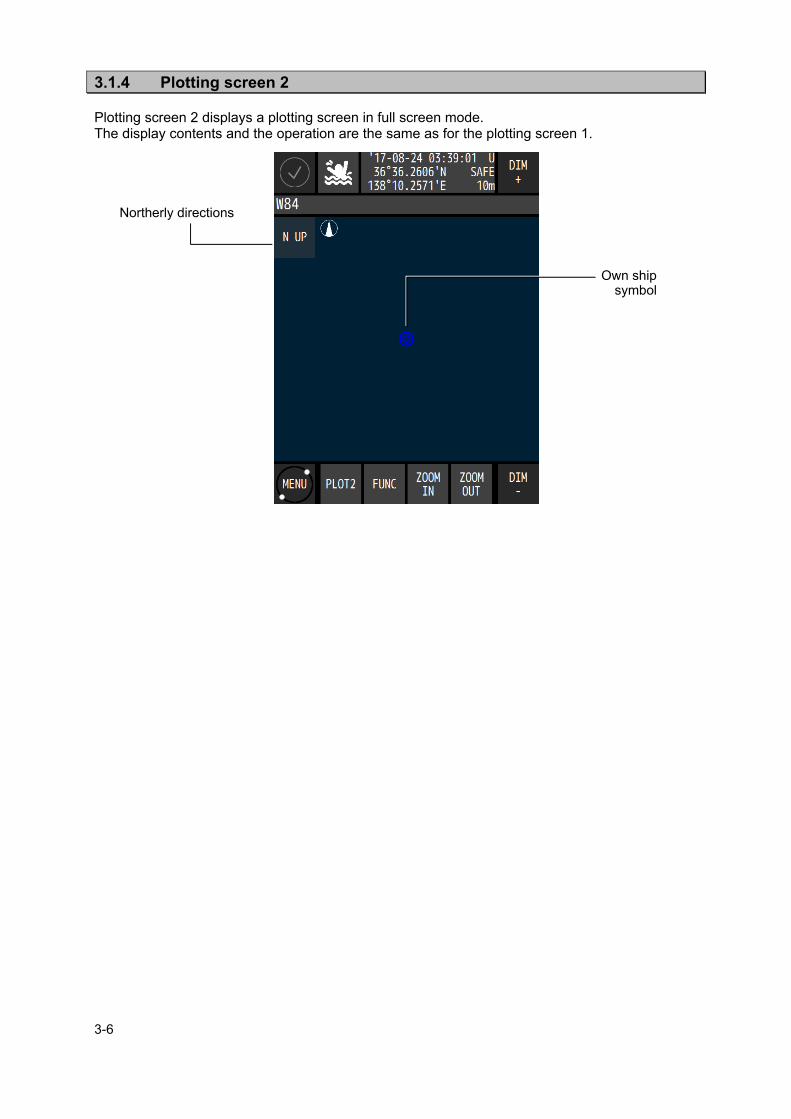
3.1.4 Plotting screen 2 Plotting screen 2 displays a plotting screen in full screen mode. The display contents and the operation are the same as for the plotting screen 1.
Own ship symbol
Northerly directions

3-7
3.1.5 Analogue screen The analogue screen displays the course, waypoint bearing, and CDI in graphic format. During route execution, the screen displays the off-course and distance to the waypoint.
The ship speed meter can be displayed by using or .
Main screen
Bearing from the own ship's position to the waypoint
Course indicator bar |:Course ▼:Bearing from the own ship's position to the waypoint
Sub screen (Speed)
Route deviation indicator bar
Deviation from the route
Course
Distance from the own ship's position to the waypoint
Speed
Center of the route

3-8
3.1.6 Highway screen The highway screen displays the CDI, course, speed, bearing, and distance. The highway screen displays information in Course Up mode while the own ship's position is fixed, so the route turns when the own ship turns. As a result, the route may not be displayed depending on the course.
The screen can be enhanced or reduced by using and respectively.
3.1.7 Satellite information screen The satellite information screen displays the GNSS satellite and the beacon reception state.
The GNSS system can be switched by using or .
Waypoint direction
Next waypoint Waypoint
Own ship Speed
Course Distance from the own ship's position to the waypoint
Bearing from the own ship's position to the waypoint
Route Width of the starboard-side route
Scale bar Width of the
port-side route
Deviation from the route and the steering direction : Steered to the left : Steered to the right
GNSS satellite location and the receiving status : Completion of
demodulation : Use of position fixing Unframed: Search
GNSS satellite number Unframed: Search □ : Completion of
demodulation ■ : Use of position fixing
GNSS signal intensity bar 45 to 55 under normal conditions
Beacon frequency
Beacon SNR Beacon error rate
GNSS HDOP
Antenna height
Beacon bit rate Beacon signal intensity

3-9
3.1.8 Waypoint information screen The waypoint information screen displays waypoint information on the route.
The information can be switched to the next waypoint information by using or .
3.1.9 Beacon text screen The beacon text screen displays the beacon text information (Type 16) that is received by the beacon receiver. Beacon text information can be deleted ( FUNK → BEACON DELETE) .
Waypoint number n-th waypoint
Comment on the waypoint
Waypoint position
Bearing from the own ship's position to the displayed waypoint
Expected arrival time at the displayed waypoint
Distance from the own ship's position to the displayed waypoint
Time required for reaching the displayed waypoint
Width of the port and starboard-side route
Arrival-circle radius
Planned ship speed
Total number of waypoints
Beacon information
Next page Previoue page

3-10
3.1.10 Navigation aid screen The navigation aid screen calculates and displays navigation information including a 4-split screen, navigation measurement, trip distance, external equipment information, and distance between two points.
The screen can be switched by using or .
CTS Distance from the own ship's position to the waypoint
Time required for reaching the waypoint
Deviation from the route
Navigation assistance screen 2 (measurement for navigation)
Course Speed
measurement start time
Total time
measurement end time
Own ship position
Speed Course
RUNNING: Measurement in progress END: Measurement complete
Trip Total distance
Navigation assistance screen 1

3-11
Navigation assistance screen 5 (Calculation of a distance/bearing between two points)
Navigation assistance screen 4 (External equipment screen)
Forward/backward speed through water ▲:Forward ▼:Backward
Water depth
Water temperature
Current direction, speed and depth. Layer A Layer B Layer C Layer D Layer E
Stern speed through water Leftward Rightward
measurement start time measurement end time
Total time Average speed
trip
RUNNING: Measurement in progress END: Measurement complete
RUNNING: Measurement in progress END: Measurement complete
measurement start time
Total time measurement end time
Average speed trip
Starting point (Latitude and longitude) Terminal point
(Latitude and longitude)
Distance calculation method GC: Great circle sailing RL: Rhumb line sailing Distance
Bearing
Baw speed through water Leftward Rightward
Navigation assistance screen 3 (measurement for Trip)

3-12

4-1
Chapter 4 Operation
4.1 Menu List
4.1.1 Main Menu MENU Sub Menu Sub Menu Sub Menu Range Reference
DISPLAY
THEME DAY/DUSK/NIGHT 4.3.1 BEEP OFF / ON 4.3.2 DAY SCREEN OFF / ON 4.3.3 NAV OFF / ON 4.3.4 PLOT OFF / ON 4.3.4 ANALOG OFF / ON 4.3.4 HIGHWAY OFF / ON 4.3.4 SAT INFO OFF / ON 4.3.4 WPT INFO OFF / ON 4.3.4 BEACON TEXT OFF / ON 4.3.4 NAV ASSIST OFF / ON 4.3.4
VOYAGE
WPT WPT LIST 4.4.1 ROUTE ROUTE LIST 4.5.1 RUN 4.6.1
EVENTMARK EVENTMARK LIST
4.7.1
WPT COPY 4.4.4 ROUTE COPY 4.5.4 WPT DELETE 4.4.5 ROUTE DELETE
4.5.5
EVENT DELETE 4.7.5
SHARED ROUTE SEND 4.5.6 ROUTE RECEIVE SOURCE IP 4.5.6
DEFAULT SETTINGS
WIDTH PORT(NM)
0.00~9.99 4.5.7
WIDTH STBD(NM)
0.00~9.99 4.5.7
ARRIVAL RADIUS(NM)
0.00~9.99 4.5.7
SPEED(kn) 00.00~99.99 4.5.7 SAIL GC/RL 4.5.7 SOG SMOOTHING(s)
0~99 4.5.7
ALERT
SYSTEM SET OFF / ON 4.10.1 SOUND OFF / ON 4.10.1
ARRIVAL/ ANCHOR
SET OFF / ARRIVAL / ANCHOR
4.10.1
SOUND OFF / ON 4.10.1
XTD/ BOUNDARY
SET OFF / XTD / BOUNDARY
4.10.1
SOUND OFF / ON 4.10.1
HDOP SET 4.10.1 SOUND OFF / ON 4.10.1
SPD SET 4.10.1 SOUND OFF / ON 4.10.1
TRIP SET 4.10.1 SOUND OFF / ON 4.10.1
EARLY COURSE CHANGE
SET 4.10.1
SOUND OFF / ON 4.10.1
END OF TRACK SET 4.10.1 SOUND OFF / ON 4.10.1
ARRIVED AT WOL
SET OFF / ON 4.10.1 SOUND OFF / ON 4.10.1

4-2
MENU Sub Menu Sub Menu Sub Menu Range Reference
ALERT
ACTUAL COURSE CHANGE
SET OFF / ON 4.10.1
SOUND OFF / ON 4.10.1
TEMP SET 4.10.1 SOUND OFF / ON 4.10.1
DPTH SET 4.10.1 SOUND OFF / ON 4.10.1
DGPS SET
OFF GPS→DGPS DGPS→GPS GPS⇔DGPS
4.10.1
SOUND OFF / ON 4.10.1
BUFFER SET OFF / ON 4.10.1 SOUND OFF / ON 4.10.1
POWER SET OFF / ON 4.10.1 SOUND OFF / ON 4.10.1
GNSS SETTING
SENSOR1
GNSS GPS MODE GPS 4.12.1 FIX MODE 2D / 3D / AUTO 4.12.2 ELV MASK 5~89 deg 4.12.3 HDOP 4/10/20 4.12.4
SMOOTH
POSN SMOOTHING(s)
0~99 4.12.5
SPEED SMOOTHING(s)
0~99 4.12.5
COURSE SMOOTHING(s)
0~99 4.12.5
RAIM RAIM ACCURACY LEVEL(m)
OFF/10/30/50/100 4.12.6
DATUM 4.12.7
INIT
QUADRANT 4.12.8 LAT 4.12.8 LON 4.12.8 ANT HEIGHT(m) 4.12.8 YEAR 4.12.8 MONTH 4.12.8 DAY 4.12.8 HOUR(hr) 4.12.8 MINUTE(min) 4.12.8
DGPS OFF / AUTO BEACON / SBAS
4.12.9
BEACON
AUTO 4.12.10
MANUAL FREQUENCY/ BITRATE
4.12.10
SEMI AUTO 4.12.10 MONITOR 4.12.10
SBAS SAT SEARCH
AUTO / MANUAL (SBAS SETTING)
4.12.11
TYPE0 OFF / ON 4.12.11 RANGING OFF / ON 4.12.11
STN LIST 4.12.12

4-3
MENU Sub Menu Sub Menu Sub Menu Range Reference
GNSS SETTING
SENSOR2
GNSS GPS MODE GPS Same as Sensor1 FIX MODE 2D / 3D / AUTO
ELV MASK 5~89 deg HDOP 4/10/20
SMOOTH
POSN SMOOTHING(s)
0~99
SPEED SMOOTHING(s)
0~99
COURSE SMOOTHING(s)
0~99
RAIM RAIM ACCURACY LEVEL(m)
OFF/10/30/50/100
DATUM
INIT
QUADRANT LAT LON ANT HEIGHT(m) YEAR MONTH DAY HOUR(hr) MINUTE(min)
DGPS OFF / AUTO BEACON / SBAS
BEACON
AUTO
MANUAL FREQUENCY/ BITRATE
SEMI AUTO MONITOR
SBAS SAT SEARCH
AUTO / MANUAL (SBAS SETTING)
TYPE0 OFF / ON RANGING OFF / ON
STN LIST
SYSTEM
DATE / TIME
TIME DIFF +00:00~+13:30 4.13.1
DATE DISP ‘YY-MM-DD DD MMM,’YY MMM DD,’YY
4.13.1
TIME DISP(hr) 12hr / 24hr 4.13.1
UNIT DIST / SPEED
NM,kn km,km/h mi,mi/h
4.13.2
HIGHT / DPTH m / ft / fm 4.13.2 TEMP ℃ / F 4.13.2
MAG CORR 4.13.3 LORAN OFF / LORAN A,C 4.13.4 SENSOR SELECT
AUTO/ SENSOR1,2 4.13.5
LANGUAGE JAPANESE/ ENGLISH
4.15
VERSION
DISPLAY 4.16 PROCESSOR 4.16 SENSOR1 4.16 SENSOR2 4.16
ALERT LIST
ALERT HISTORY
4.11.1
ACTIVE ALERT 4.11.2 LAN1 4.11.3 LAN2 4.11.3

4-4
MENU Sub Menu Sub Menu Sub Menu Sub Menu Range Reference
EQUIP
TYPE
TYPE1 / 2 DISPLAY
DISPLAY TYPE
MAIN REMOTE(LAN) REMOTE (SERIAL)
―
SFI GP0000 ―
TYPE2/2 PROCESSOR
DEVICE No. No1.~No3. ― SFI GP0000 ―
SENSOR1
OFF GPS COMPASS OTHER EQUIP
―
SENSOR2
OFF GPS COMPASS OTHER EQUIP
―
DATA I/O
IN/OUT1 ― IN/OUT2 ― IN/OUT3 ― OUT4 ― OUT5 ― OUT6 ―
LAN
LAN1
DATA OUT ― RMS SEND
―
PRINTER ―
LAN2
DATA OUT ― RMS SEND
―
PRINTER ―
COMMON
ACTIVE ROUTE
―
DATA ROUTE
―
MUTUAL ―
CONTACT1 CONTACT OUT
―
CONTACT2 CONTACT OUT
―
CONTACT3 CONTACT OUT
―
CONTACT4 CONTACT OUT
―
BUFFER
FORMAT ― BITRATE(bps) ― VERSION ― TALKER ―
SENSOR
SENSOR1 PORT2(bps)
4800 / 9600 19200 / 38400
―
SENSOR2 PORT2(bps)
4800 / 9600 19200 / 38400
―
RS-232C
FORMAT ― BITRATE(bps) ― VERSION ― TALKER ―
SWITCH
CONTROLL METHOD
OFF MFD FIX/NOFIX FIX/NOFIX + DOP
―
SWITCH SELECTION
PROCESSOR No1. PROCESSOR No2.
―
4-5
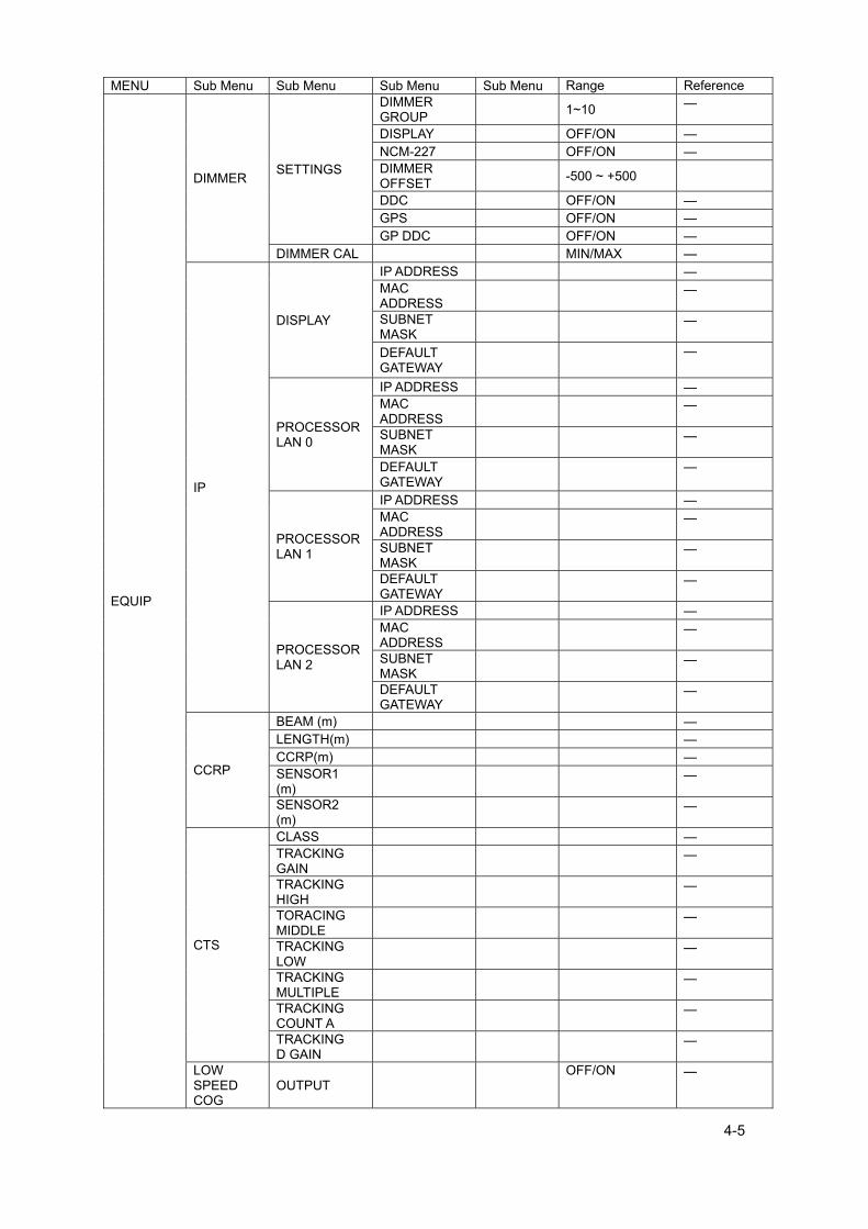
MENU Sub Menu Sub Menu Sub Menu Sub Menu Range Reference
EQUIP
DIMMER SETTINGS
DIMMER GROUP
1~10 ―
DISPLAY OFF/ON ― NCM-227 OFF/ON ― DIMMER OFFSET
-500 ~ +500
DDC OFF/ON ― GPS OFF/ON ― GP DDC OFF/ON ―
DIMMER CAL MIN/MAX ―
IP
DISPLAY
IP ADDRESS ― MAC ADDRESS
―
SUBNET MASK
―
DEFAULT GATEWAY
―
PROCESSOR LAN 0
IP ADDRESS ― MAC ADDRESS
―
SUBNET MASK
―
DEFAULT GATEWAY
―
PROCESSOR LAN 1
IP ADDRESS ― MAC ADDRESS
―
SUBNET MASK
―
DEFAULT GATEWAY
―
PROCESSOR LAN 2
IP ADDRESS ― MAC ADDRESS
―
SUBNET MASK
―
DEFAULT GATEWAY
―
CCRP
BEAM (m) ― LENGTH(m) ― CCRP(m) ― SENSOR1 (m)
―
SENSOR2 (m)
―
CTS
CLASS ― TRACKING GAIN
―
TRACKING HIGH
―
TORACING MIDDLE
―
TRACKING LOW
―
TRACKING MULTIPLE
―
TRACKING COUNT A
―
TRACKING D GAIN
―
LOW SPEED COG
OUTPUT OFF/ON ―

4-6
MENU Sub Menu Sub Menu Sub Menu Sub Menu Range Reference
EQUIP
MAINTENANCE
DIAGNOSIS
DISPLAY ― PROCESSOR ― SENSOR1 ― SENSOR2 ―
MONITOR
DATA IN1 ― DATA IN2 ― DATA IN3 ― RS-232C ― SWITCH ― LAN1 ― LAN2 ― SENSOR1 ― SENSOR2 ―
OPERATING TIME
OPERATING TIME(hr)
―
LCD TIME(hr) ― RESET ―
DEMO
DEMO TYPE ― START/ STOP ― YEAR ― MONTH ― DAY ― HOUR(hr) ― MINUTE(min) ― SECOND(s) ― QUADRANT ― LAT ― LON ― SPEED(kn) ― COURSE(°) ― RADIUS(NM) ― ROUTE ―
ALL SETTING VALUE
BACKUP INFO ―
IMPORT/ EXPORT
MPORT/ EXPORT
PROCESSOR →DISPLAY DISPLAY →PROCESSOR
―
PROCESS BACKUP/ OVERWRITE
―

4-7
4.1.2 Function menu
DISPLAY FUNC
COMMON
PRINT Outputs data to a printer. GOTO Sets a waypoint. EVENT Registers the own ship’s position in the event mark list. DIMMER DEFAULT Resets the dimmer setting to the default value.
PLOT1/PLOT2
MARK Displays a mark at the cursor position. CURSOR MODE Displays a cursor. HOME Moves own ship to the centre of the screen. PLOT Sets display/non-display on the plotting screen. BACK GROUND COLOUR Changes the background colour of the plotting screen.
ANALOG SPEED METER Sets the maximum value of the ship speed meter. HIGHWAY BACK GROUND COLOUR Changes the background colour of the HIGHWAY screen.
SAT INFO NEAREST STN Displays the nearest beacon station. JLR-8600 does not support this function.
BEACON TEXT BEACON DELETE
Deletes the received data. JLR-8600 does not support this function.
BUZZER Sets whether to sound a buzzer when TYPE16 is received.
NAV ASSIST
CALC START Starts distance calculation. TRIP RESET Stops trip distance calculation. TOTAL TRIP RESET Resets the total trip distance. TRIP 1 CAL START/END Starts/Stops distance calculation of TRIP1. TRIP 2 CAL START/END Starts/Stops distance calculation of TRIP2. TRIP 1 RESET Resets distance calculation of TRIP1. TRIP 2 RESET Resets distance calculation of TRIP2. CURRENT SETTING Sets the layer of the current to be displayed. CALC SETTING Sets the position of two points between which the distance
is to be calculated.
4-8
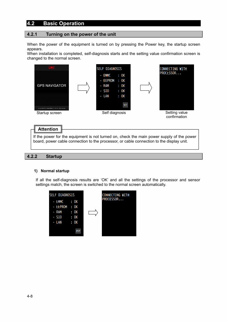
4.2 Basic Operation
4.2.1 Turning on the power of the unit When the power of the equipment is turned on by pressing the Power key, the startup screen appears. When installation is completed, self-diagnosis starts and the setting value confirmation screen is changed to the normal screen.
4.2.2 Startup
1) Normal startup
If all the self-diagnosis results are ‘OK’ and all the settings of the processor and sensor settings match, the screen is switched to the normal screen automatically.
If the power for the equipment is not turned on, check the main power supply of the power board, power cable connection to the processor, or cable connection to the display unit.
Attention
Startup screen Self diagnosis Setting value confirmation

4-9
2) Error startup 1
The message that is shown below may be displayed in the receiver diagnosis. This message is displayed when the setting values do not match between the processor and the receiver due to the equipment replacement or other reason. In this case, select one of the following items. [USE SENSOR CONFIG.]: The setting value of the processor is rewritten so as to
match the setting value of the receiver. [USE PROCESSOR CONFIG.]: The setting value of the receiver is rewritten so as to match
the setting value of the processor.
3) Error startup 2
If any one of the diagnosis results is ‘NG’, the result will be displayed continuously. The screen is not switched to the normal screen unless “SKIP” is tapped.
4.2.3 Turning off the power of the unit When the Power key is pressed, the following message is displayed. When “YES” is selected, the power is turned off.
When there is any error (NG), contact Nippon Signal or your distributor.
Attention
Even if the message is displayed, the power of the display is turned off forcibly if the
Power key is held down for about 8 seconds. In this case, the power of the display is turned off, but the processor operates continuously.
When the display unit is energised even if the power is Off, the LED of the Power key is lit.
Memo
POWER OFF ARE YOU SURE

4-10
4.2.4 Adjusting the backlight The brightness can be adjusted to 17 levels/OFF by using the DIM key. Even if the brightness is set to OFF, the DIM key alone remains lit.
To reset the brightness to the default value, tap from .
1. Whenever “DIM+” at the top right corner of the screen is pressed, the screen brightness
increases. 2. Whenever “DIM-” at the bottom of the screen is pressed, the screen brightness decreases and
finally is set to OFF.
4.2.5 Menu operation When the MENU key is pressed, a menu is displayed. When the MAIN key is pressed while a menu is displayed, the screen returns to the normal screen. For the details of the menu, refer to “4.1 Menu List”.

4-11
4.2.6 Alert and acknowledgment (ACK) 1. Notifying the occurrence of an alert
When an alert occurs, an alert icon is displayed at the top left corner of the screen and the occurrence of an alert is notified by a buzzer sound. The alert target value is displayed with blinking.
Icon list
Icon Priority Status
Alarm Active-Unacknowledged
Active-Silenced
Active-Acknowledged
Rectified- Unacknowledged
Warning Active-Unacknowledged
Active-Silenced
Active-Acknowledged
Rectified- Unacknowledged
Caution Active
When any icon is tapped, an alert display bar is displayed at the centre of the screen. 2. Alert acknowledgment (ACK) 1) Tap the alert detail bar at the centre of the screen. 2) The alert icon changes to the acknowledged state and the buzzer sound stops. When a NOFIX
alert occurs, the alert target value that is displayed is lit in yellow.
When multiple alerts occur simultaneously, the alert with the highest priority is
displayed first and all the alerts must be acknowledged.
Even if the alert is rectified before being acknowledged, the “Unacknowledged” state icon is displayed. All the alerts that have occurred must be acknowledged.
Memo

4-12
Screen transition at the occurrence of an alert
5. The alert contents are cleared.
3. Alert is occurring The alert contents are displayed.
4. Alert occurred (acknowledged)
Acknowledge by tapping the alert contents.
The icon indicating an acknowledged state is displayed.
1. Operating normally 2. Alert occurred (Non ACK)
6. Rectified
An alert occurrence icon is displayed.
Tap the alert occurrence icon.
Alert occurred
Rectified.
Tap the icon indicating an acknowledged state.

4-13
4.2.7 Screen operation See below for the screen operation.
4.2.8 Inputting numeric values Numeric value input by numeric keys is allowed for the setting values with blue underline. Tap the blue underline of the numeric item to be input.
Enter a numeric value and confirm with .
Menu level
+/- setting value switching
Page
Blue underline Indicates that numeric key input is enabled.
Setting item
Setting value
Return to the main screen
Page feed (< >) Move to the next page
Confirm
Deletes 1 character.
Returns to the previous screen by discarding the editing on this screen.
Maintains the screen by discarding the editing on this screen.
Returns to the top menu by discarding the editing on this screen.
Returns to the full screen by confirming the editing on this screen.

4-14
4.2.9 Inputting comments Input of characters by using numeric keys is allowed for the setting items with blue underline. Tap the blue underline of the setting item to be input. Change the input mode by tapping ABC (characters), #&$ (symbols), or 123 (numeric values). Display the character or numeric value that is assigned to the key by tapping it. When entering the same character or symbol consecutively, take a small interval between them.
Enter a character and confirm it with .
ABC #&$
123

4-15
4.2.10 List operation This section shows the list operation method. The same operation method is applied for a waypoint list, a route list, and an event mark list.
When the list is empty, the following message is displayed.
4.2.11 Entering a password in CODE INPUT Some setting items are protected by a password to prevent them being changed easily. If the power is turned off or no operation is performed for five minutes after a password is set, the password is reset. To set a password, enter a password again in CODE INPUT. Procedure
1.
2. Enter a password and confirm it with .
Entered password Indicated by ****.
Menu level Page
No. of waypoints registered/total number of waypoints that can be registered
Page feed (< >) Move to the next page.
List content display area
The number input screen is displayed and control jumps to the input number.
Jumps to the previous free number
Jumps to the next free number

4-16
4.3 Setting Display Set a screen. Set a THEME, a beep tone, and background colour.
4.3.1 Setting a theme Screen brightness can be adjusted according to the time zone for using this equipment. Procedure
1. THEME
4.3.2 Setting a beep tone Set a beep tone ON/OFF when the screen is tapped. Procedure
1. BEEP
4.3.3 Setting reverse video display Set the background colour to white/black. Procedure
1. DAY SCREEN
THEME Description DAY Specify this when using the equipment during daytime. DUSK Specify this when using the equipment at dusk. NIGHT Specify this when using the equipment at night.
BEEP Description ON Sets the beep tone to ON. OFF Sets the beep tone to OFF.
DAY SCREEN Description ON Sets the background colour to white. OFF Sets the background colour to black.

4-17
4.3.4 Selecting a display screen A screen to be displayed can be selected. It is not possible to set all the screens to non-display. Procedure
1. → Select a display.
DISPLAY Description NAV
ON: Set to Display. OFF: Set to Non-display.
PLOT1 PLOT2 ANALOG HIGH WAY SAT INFO WPT INFO BEACON TEXT NAV ASSIST

4-18
4.4 Registering Waypoints
To execute a route, a waypoint must be registered in a waypoint list. This equipment allows registration of 10000 waypoints. A waypoint list is divided into three areas and it is managed by numbers from 1 to 11024.
1 to 10000: Waypoints that are registered in this equipment are registered. 10001 to 10512: Waypoints of the shared active routes that are sent from ECDIS are registered. 10513 to 11024: Waypoints that were used by a temporary route are registered.
While waypoints from number 1 to number 10512 are saved and are not cleared even if the power is turned off, waypoints from number 10513 to number 11024 are cleared if the power is turned off.
Waypoints can be set up to North latitude/South Latitude 89 degrees.
4.4.1 Displaying a waypoint list Registered waypoints (waypoint numbers from 1 to 10000) can be displayed. Waypoint number 00001 is registered as “HOME PORT”. Procedure
1. A waypoint list is displayed.
The position that is registered in HOME in a waypoint list can be set easily as a
waypoint by the GOTO function. It is useful to register a point that is set as a waypoint frequently (such as home port).
The GOTO function can be set from on each screen.
Memo
Symbol Waypoint number Position
Comment
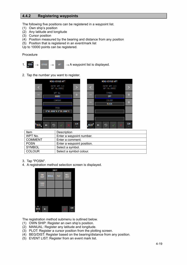
4-19
4.4.2 Registering waypoints The following five positions can be registered in a waypoint list. (1) Own ship’s position (2) Any latitude and longitude (3) Cursor position (4) Position measured by the bearing and distance from any position (5) Position that is registered in an event/mark list Up to 10000 points can be registered. Procedure
1. A waypoint list is displayed.
2. Tap the number you want to register.
3. Tap "POSN". 4. A registration method selection screen is displayed. The registration method submenu is outlined below. (1) OWN SHIP: Register an own ship’s position. (2) MANUAL: Register any latitude and longitude. (3) PLOT: Register a cursor position from the plotting screen. (4) BEG/DIST: Register based on the bearing/distance from any position. (5) EVENT LIST: Register from an event mark list.
Item Description WPT No. Enter a waypoint number. COMMENT Enter a comment. POSN Enter a waypoint position. SYMBOL Select a symbol. COLOUR Select a symbol colour.

4-20
(1) When selecting OWN SHIP
a) Tap .
b) Set a comment, a symbol, and a colour, and tap .
(2) When selecting MANUAL
a) Tap .
b) Set a comment, a symbol, and a colour, and tap .
(3) Selecting PLOT
a) Tap .
b) A plotting screen is displayed. c) Move the cursor to the position you want to register by using the Up/Down/Left/Right
arrows. d) Tap "SET". e) The cursor position is registered.
f) Set a comment, a symbol, and a colour and tap .
Item Description QUADRANT Select North latitude/South latitude/East latitude/West latitude
of the latitude/longitude. NE North latitude/East latitude NW North latitude/West latitude SE South latitude/East latitude SW South latitude/West latitude
LAT Enter a latitude. LON Enter a longitude.
Cursor position Bearing/distance from own ship to the cursor position
Registered waypoint
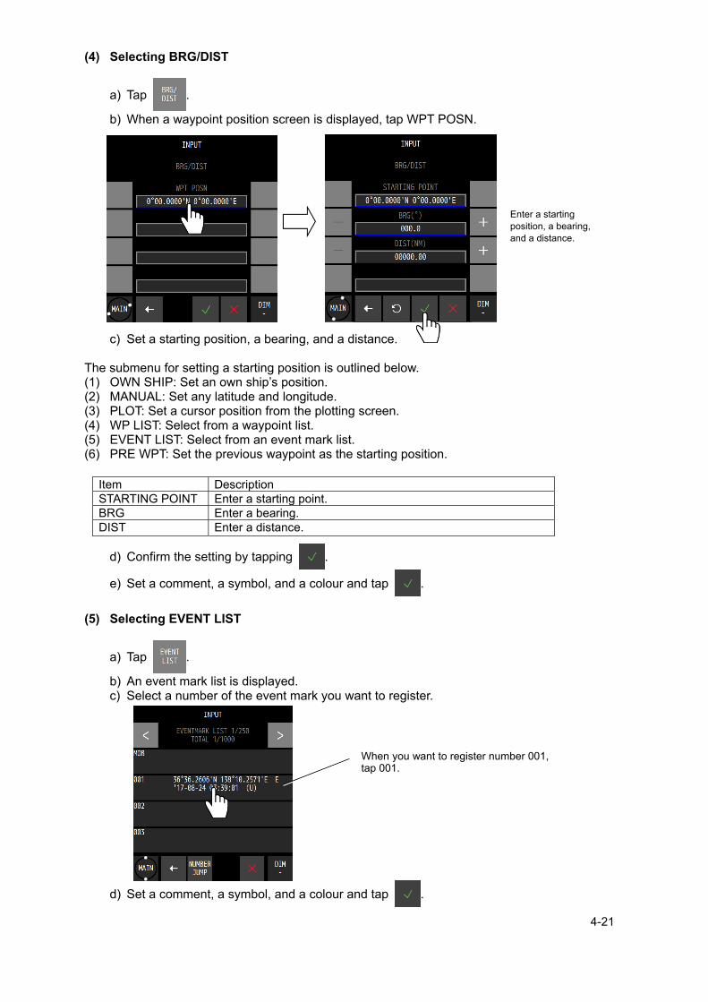
4-21
(4) Selecting BRG/DIST
a) Tap .
b) When a waypoint position screen is displayed, tap WPT POSN.
c) Set a starting position, a bearing, and a distance. The submenu for setting a starting position is outlined below. (1) OWN SHIP: Set an own ship’s position. (2) MANUAL: Set any latitude and longitude. (3) PLOT: Set a cursor position from the plotting screen. (4) WP LIST: Select from a waypoint list. (5) EVENT LIST: Select from an event mark list. (6) PRE WPT: Set the previous waypoint as the starting position.
d) Confirm the setting by tapping .
e) Set a comment, a symbol, and a colour and tap .
(5) Selecting EVENT LIST
a) Tap .
b) An event mark list is displayed. c) Select a number of the event mark you want to register.
d) Set a comment, a symbol, and a colour and tap .
Item Description STARTING POINT Enter a starting point. BRG Enter a bearing. DIST Enter a distance.
Enter a starting position, a bearing, and a distance.
When you want to register number 001, tap 001.

4-22
4.4.3 Editing waypoints Registered waypoint information (symbol shape, comment, and waypoint position) can be
edited. The waypoint on the route that is currently being executed cannot be edited.
Procedure
1. A waypoint list is displayed.
2. Tap the number you want to edit. 3. Tap the item you want to edit and edit the item.
4. After editing, tap .
To edit a position, refer to “4.4.2 Registering waypoints”. A symbol, a colour, and a comment can be edited from the plotting screen. For the editing method, refer to “4.8.10 Displaying symbol information”.
4.4.4 Copying waypoints Waypoint information can be copied on to another waypoint number. Information on an event
and a mark can be copied on to a waypoint list. Number 1 in a waypoint list is handled as HOME.
Waypoints that are saved under numbers from 10001 to 10512 and are used by the shared active route that is sent from ECDIS are automatically overwritten when next route is sent. Waypoints to be kept must be copied under numbers between 1 and 10000.
Waypoints of a temporary route that are saved under numbers from 10513 to 11024 are cleared when another temporary route is created or the power is turned off. Waypoints to be kept must be copied under numbers between 1 and 10000.
When no free area is available, waypoints can be overwritten. However, waypoints cannot be overwritten to those that are used by the route.
Procedure
1.
2. Enter a starting point and an ending point of the copy source.
When only one point is to be copied, enter the same number for a starting point and an ending point.
3. Tap a copy destination. The copy destination submenu is outlined below.
(1) Any input: Enter an input number. (2) Waypoint list: Specify from a waypoint list.
(1) Any input
Enter a starting point of the copy destination. (2) Waypoint list
When a waypoint list is displayed, tap a number of the copy destination.

4-23
4. Confirm the operation by tapping .
4.4.5 Deleting waypoints Waypoints registered from numbers 1 to 10000 can be deleted. Waypoints on the route that is currently executed cannot be deleted. If a waypoint is on the route that is not being executed is deleted, the waypoint is deleted from
the route also.
Procedure
1.
2. Tap a deletion source. A deletion source submenu is outlined below.
(1) Any input: Enter a waypoint number to be deleted. (2) Waypoint list: Specify from a waypoint list. (3) ALL: All the waypoints are deleted.
(1) Any input
Enter a starting point and an ending point of the number of the waypoint to be deleted. When deleting one point only, enter the same number for a starting point and an ending point.
(2) Waypoint list
When a waypoint list is displayed, select a starting point and an editing point of the waypoints to be deleted. When deleting one point only, enter the same number for a starting point and an ending point.
(3) All
All the waypoints are deleted. 3. The range to be deleted and the number of waypoints to be deleted are displayed.
4. Confirm the selection by tapping .
Waypoints can be deleted from a plotting screen. For the editing method, refer to “4.8.10 Displaying symbol information”.
When selecting copy sources with consecutive numbers, numbers that cross over a
boundary such as 10000 or 10512 cannot be selected.
Example) Numbers from 9999 to 10001 or numbers from 10511 to 10513 cannot be selected.
Memo

4-24
4.5 Route Plan A route can be created by using registered waypoints. Up to 100 routes can be created in this equipment and up to 512 waypoints can be specified
per route. Waypoint information can be set for each LEG such as a route width, an arrival radius, and GC/RL. For the waypoint information that can be set, refer to “4.5.1 Displaying a route list”.
A created route can be shared with external equipment such as ECDIS. A created route is registered in a route list. A route list is divided into three areas and is managed by numbers from 1 to 102.
Numbers from 1 to 100: The route that was created in this equipment is registered. Number 101: The shared active route that is sent from ECDIS is registered. Number 102: A temporary route is registered.
Since routes from numbers 1 to 101 are saved, they are not cleared even if the power is turned off. However, route number 102 is cleared if the power is turned off since it is not saved.
4.5.1 Displaying a route list Routes that were created can be displayed in a route list. Information on each LEG of the route and waypoint information of each LEG can be displayed. The required time cannot be calculated for the route that contains the LEG without planned ship speed. Procedure
1. A route list is displayed.
When a registered route is tapped, the LEG information can be displayed.
Number of waypoints on the route
Total route distance Total time required for
the routes
Number of pages of the route list
Number of routes registered
Comment

4-25
4.5.2 Creating routes To create a route, determine a route number and sequentially select the waypoints, which are
turn points. The same waypoint cannot be selected continuously. Up to 100 routes can be created. Up to 512 waypoints can be set per route. Either a TCS route or a normal route can be selected. Procedure
1. A route list is displayed.
2. Tap a number to be registered.
3. Tap .
4. Tap .
When a waypoint input screen is displayed, tap 001.
Item Description ROUTE ARRIVAL CIRCLE Creates a normal route.
WHEEL-OVER LINE(WOL) Creates a TCS route. COMMENT Enter a comment.
Number of the displayed waypoint
Route number currently being created

4-26
5. Set each item and tap .
First waypoint is set. To set two or more waypoints, repeat from Step 4. 6. Set a waypoint and tap .
Item Description POSN When "POSN" is tapped, a waypoint list is displayed.
Select a waypoint position from the waypoint list. COMMENT A comment cannot be set for a waypoint.
It can be edited from the waypoint list. SYMBOL A waypoint symbol cannot be set.
It can be edited from the waypoint list. COLOUR A colour of a waypoint cannot be set.
It can be edited from the waypoint list. ARRIVAL RADIUS Set an arrival radius. WIDTH PORT Set a port route width. WIDTH STBD Set a starboard route width. SPEED Set a planned ship speed. SAIL Route distance calculation method for LEG
GC: Calculated by the great circle sailing. RL: Calculated by the Meridional part sailing (Rhumb Line).
STATE Set whether to use the waypoint. USE: Use the waypoint. SKIP: Although the waypoint is kept on the route, it is skipped. DELETE: The waypoint is deleted from the route. It is kept in the waypoint
list. Waypoints of the route that is currently being executed cannot be deleted.
ROT This item can be set for a TCS route only. Set a Rate Of Turn.
TURN RADIUS This item can be set for a TCS route only. Set a turn radius.
TIME ZONE This item can be set for a TCS route only. Set a time zone.
Bearing from the previous waypoint
LEG distance
GC/RL
Waypoint SKIP

4-27
4.5.3 Editing routes Waypoint addition, change, and deletion are allowed for routes. Procedure
1. A route list is displayed.
2. Tap a route you want to edit. 3. Tap 4. Tap a waypoint you want to edit.
5. Set a waypoint and tap .
Headers can also be edited in the same way.
Item Description END ADD Adds the final waypoint. INSERT Adds a waypoint before the waypoint that is tapped. EDIT Edits the waypoint that was tapped. DELETE Deletes the waypoint that was tapped from the route.
Tap a route you want to edit Tap a waypoint you want to edit
Route list Display of waypoints on the route

4-28
4.5.4 Copying routes The route that was created can be copied on to a different route number. The waypoint that is used by the shared active route and is sent from ECDIS and is saved in number 101 is overwritten automatically when the next route is sent. Routes that are to be saved must be copied on to numbers between 1 and 100. The waypoint of a temporary route that is saved under number 102 is cleared when another temporary route is created or the power is turned off. To save the route, the route must be copied on to a number between 1 and 100. Routes of consecutive numbers can be copied in bulk. When no free area is available, a route can be overwritten. However, the route that is being executed cannot be overwritten. Select a copy source and specify a copy destination number. When a temporary route or a shared route is to be copied, the waypoints must also be copied. Procedure
1.
2. Tap "COPY ORG" and enter a number of a starting point and an ending point of the copy
source. The input method is outlined below. (1) MANUAL: Enter an ending point and a starting point. (2) ROUTE LIST: Select from the route list. When copying one point only, enter the same number for a starting point and an ending point.
(1) MANUAL input
a) Tap .
(2) Selecting from a ROUTE LIST
a) Tap .
b) Tap a starting point and an ending point on the route list.
Item Description FROM Set a starting number. TO Set an ending number.
Copy source
Total number of routes
Copy destination

4-29
c) Confirm the setting by tapping .
3. Tap "COPY DEST" and enter a starting point of the copy destination.
The input method is outlined below. (1) MANUAL: Enter an ending point. (2) ROUTE LIST: Select from the route list.
(1) MANUAL input
a) Tap .
b) Confirm the setting by tapping .
(2) Select from a ROUTE LIST
a) Tap .
b) Tap a copy destination on the route list.
c) Confirm the setting by tapping .
4. Execute by tapping .
4.5.5 Deleting routes Registered routes from numbers 1 to 100 can be deleted. The waypoints of the route to be deleted can be deleted concurrently. When deleting waypoints also, the waypoints that are used by another route cannot be deleted. An Active route cannot be deleted. Procedure
1.
Item Description INSART Set a copy destination number.
Deletion method
Total numbers selected
Numbers to be deleted

4-30
2. Tap "DELETE" and enter a number of a starting point and an ending point of the deletion
source. The input method is outlined below. (1) MANUAL: Enter an ending point and a starting point. (2) ROUTE LIST: Select from the route list. (3) ALL: All the routes are deleted. When copying one point only, enter the same number for a starting point and an ending point.
(1) MANUAL input
a) Tap .
(2) Selecting from a ROUTE LIST
a) Tap .
b) Tap a starting point and an ending point on the route list.
c) Confirm the selection by tapping .
(3) Selecting ALL
a) Tap .
All the routes are selected.
3. Tap "DELETE METHOD" and select a deletion method.
4. Tap and execute the deletion.
Item Description FROM Set a starting number. TO Set an ending number.
DELETE METHOD Description ROUTE Only the selected route is deleted. The waypoint is not deleted. ROUTE+WPT The selected route and the waypoint on the route are deleted.

4-31
4.5.6 Sharing a route with another piece of equipment The route that was created by this equipment can be sent to EDCIS or a radar and also the route that was created by ECDIS can be shared by receiving it (Data route sharing). To use the route sharing function, equipment (ECDIS or radar) corresponding to the sharing must be connected to LAN. Procedure
1.
(1) Sending a route
a) Tap .
b) Set each item.
Item Descriptions ROUTE SEND Sends a route. ROUTE RECEIVE Sets route reception.
Item Description CONNECT Select multicast, unicast, or broadcast.
Normally, "multicast" is selected. IP Set a destination ID when selecting unicast.
When the multicast is selected, set to address "239.000.096.001". PORT Set a destination port when selecting unicast.
When the multicast is selected, set to port "6203". OUTPUT Set a LAN port for output. FORMAT Normally, "JRC" or "SHARE ROUTE" is selected.
NMEA VER1.5 Sends under the RTE/WPL sentence of NMEA Ver 1.5.
NMEA VER2.1 Sends under the RTE/WPL sentence of NMEA Ver 2.1. NMEA VER2.3 Sends under the RTE/WPL sentence of NMEA Ver 2.3 NMEA VER4.0 Sends under the RTE/WPL sentence of NMEA Ver 4.0. IEC Sends under the RTE/WPL sentence of IEC. JRC Sends the route in the JRC format.
Select the "JRC", when the route is shared between GPS Navigator.
SHARE ROUTE Use ROUTE to set the route to be sent. Select the "SHARE ROUTE", when the route is shared with ECDIS.
DATA Select the data to be sent. ALL WPT Sends all the waypoints.
ALL WPT+ROUTE Sends all the waypoints and routes.
SELECT WPT+ROUTE Sends the selected route and the waypoint. ALL ROUTE Sends all the routes. SELECT ROUTE Sends the selected route.

4-32
A ROUTE can be selected manually or from a route list.
c) When is tapped, the route is sent.
(2) Receiving a route
a) Tap .
b) Tap to set the sending source.
4.5.7 Setting route initial values Set an initial value of each parameter of the route. The values are applied to the route that was created by GOTO. Procedure
1.
ROUTE This item can be set when SHARE ROUTE is selected. Select a route to be sent.
TOTAL This item can be display when SHARE ROUTE is selected. Displays the number of selected routes.
Item Description SOURCE IP Set a sending source IP.
When the Active route is shared, it will not stop on the GPS even if the active route
stops with ECDIS. To stop the active route on the GPS, refer to "4.6.3 Ending a route".
Memo

4-33
2. Set each item.
3. Confirm the setting by tapping .
Item Description WIDTH PORT Set a port route width. WIDTH STBD Set a starboard route width. ARRIVAL RADIUS Set an arrival radius. SPEED Set a planned ship speed. SAIL Route distance calculation method for LEG
GC: Calculated by the great circle sailing. RL: Calculated by the Meridional part sailing (Rhumb Line).
SOG SMOOTHING Set a SOG smoothing constant. Smoothing is applied to the ship speed for calculating the estimated time of arrival and the estimated time required. Smoothing can be applied up to 99 seconds. When the estimated time of arrival fluctuates significantly, increase the smoothing value.
Do not set 0.00NM to the WIDTH PORT/STBD, route can not be shared with ECDIS.
Memo

4-34
4.6 Executing a Route A registered route or a temporary route can be executed. The following route selection methods are available.
(1) Select a route from a route list. (2) Select a waypoint by using the GOTO key. (3) Select a route by using the GOTO key. (4) Select a temporary route by using the GOTO key.
A route cannot be executed at the position exceeding North latitude/South latitude 89 degrees. For the route width, arrival radius, planned ship speed of the temporary route that was created
by GOTO, the initial values of the route are used. For the setting of route initial values, refer to “4.5.7 Setting route initial values”.
The waypoint is updated when the ship arrives at the arrival circle.
4.6.1 Executing a route by selecting from a route list A route can be executed by selecting from a route list. Procedure
1.
2. Set each item.
Item Description ROUTE Displays the route number to be executed. LEG CHANGR Select a waypoint update method.
AUTO: When the ship arrives at the arrival circle (normal route) or WOL (TSC route), the waypoint is updated automatically.
is displayed.
"WPT CHANGE" is displayed for 5 seconds. MANUAL: When the ship arrives at the arrival circle (normal route) or WOL (TSC route), the effect is notified to the user. The waypoint is to be updated manually.
is displayed.
"PLEASE PUSH "OK" AND CHANGE A ROUTE is displayed. Tap “OK”. The waypoint is updated.
DIRECTION Set an order of the waypoints to be executed. ORDER: Executes the route in the order of waypoints. REVERSE: Executes the route starting from the last waypoint.
NAVIGATION Executes the route. START: Executes the route. END: Ends the route.

4-35
3. Select “START” in "NAVIGATION".
4. Execute the route by tapping .
4.6.2 Selecting a waypoint/route by using the GOTO key When a waypoint or a route is selected by using GOTO that is assigned to “FUNC” of each screen, the route is executed towards the waypoint. When a waypoint on the route that is being executed is selected by using the GOTO key, the route restarts from the waypoint. The route that was created by GOTO is registered under route number 102 as a temporary route. Procedure
1. Each screen
The GOTO submenu is outlined below. (1) HOME: Sets HOME in the waypoint list as the waypoint. (2) WPT No.: Enter a waypoint number. (3) ROUTE No.: Enter a route number. (4) EVENT No.: Enter an event number. (5) CURSOR POSN: The cursor position is specified as the waypoint (a temporary route can be
created by setting up to 512 waypoints). (6) WPT LIST: Select from a waypoint list. (7) ROUTE LIST: Select from a route list. (8) EVENT LIST: Select from an event list. (9) ROUTE END: The route can be ended during the execution of the route. (1) Entering "HOME"
a) Tap . (2) Entering a waypoint number
a) Tap and enter a waypoint number.
b) Execute by tapping .

4-36
(3) Entering a route number
a) Tap and enter a waypoint number.
b) Execute by tapping .
(4) Entering an event number
a) Tap and enter an event number.
b) Execute by tapping .
(5) Specifying the cursor position as the waypoint
a) When is tapped, a plotting screen is displayed.
b) Move the cursor to the waypoint and tap "WPT SET".
To create a route, repeat the operation b). To delete a waypoint, tap “CLR”.
c) Tap "ROUTE SET".
Cancels GOTO processing

4-37
d) The following popup window is displayed.
(6) Selecting a waypoint from a waypoint list
a) When is tapped, a waypoint list is displayed.
b) Tap the number to be set as for the waypoint.
(7) Selecting from a route list
a) When is tapped, a waypoint list is displayed.
b) Tap the route number to be executed. c) Select a waypoint update method and an execution sequence.
d) Select “START” in "NAVIGATION".
(8) Selecting from an event list
a) Tap to display an event list. b) Tap the number to be set as the waypoint.
Item Description YES Registers the route in the route list.
When a route list is displayed, set a route number. NO Stores the route as a temporary route.
A temporary route is cleared when the power is turned off.
Item Description LEG CHANGE Select a waypoint update method.
AUTO: When the ship arrives at the arrival circle (normal route) or WOL (TSC route), the waypoint is updated automatically.
is displayed.
"WPT CHANGE" is displayed for 5 seconds. MANUAL: When the ship arrives at the arrival circle (normal route) or WOL (TSC route), the effect is notified to the user. The waypoint is to be updated manually.
is displayed.
"PLEASE PUSH "OK" AND CHANGE A ROUTE" is displayed. Tap “OK”. The waypoint is updated.
DIRECTION Set a direction of the waypoints to be executed. ORDER: Executes the route in the order of waypoints. REVERSE: Executes the route starting from the last waypoint.

4-38
(9) Ending the route that is currently being executed
a) Tap . b) The following popup window is displayed. c) Tapping YES will end the route.
4.6.3 Ending a route End a route. Procedure
1.
2. Select “END” in “NAVIGATION”.
3. Execute by tapping .
Ending by using GOTO
1.
2. Tap . 3. The following popup window is displayed. 4. Tapping YES will end the route.
ROUTE IN USE IS CANCELED ARE YOU SURE
YES NO
ROUTE IN USE IS CANCELED ARE YOU SURE
YES NO

4-39
4.7 Event/Mark Events, marks, MOB, and lines are registered in an event mark list.
4.7.1 Displaying an event/mark list All the registered events and marks can be displayed in a list. MOB is registered under event number 000. Procedure
1.
4.7.2 Registering events Register an own ship’s position as an event. Procedure
1.
Registering from a screen 1. Tap the position display section at the top of the screen.
Registration date and time U: UTC L: Local
Symbol
Event/mark number
Comment
E: Event M: Mark
Position

4-40
4.7.3 Registering marks Register a cursor position as a mark. Procedure 1. Display the PLOT1 or PLOT2 screen.
2. →
3. Display a cursor and move the cursor to the position to be marked.
4.

4-41
4.7.4 Editing events/marks Symbols, colours, and comments of events/marks can be edited. Procedure
1.
2. Tap an event or a mark to be edited.
3. Edit the symbol, colour, or comment and tap .
4.7.5 Deleting events/marks Events/marks can be deleted. Procedure
1.
The event/mark deletion submenu is outlined below. (1) EVENT MARK LIST: Select a deletion range from the event mark list. (2) ALL EVENT: Deletes all the events. (3) ALL MARK: Deletes all the marks. (4) ALL EVENT MARK: Deletes all the events/marks. (1) EVENT MARK LIST
a) When is tapped, an event mark list is displayed.
b) Tap a starting point and an ending point of the event marks to be deleted.
When deleting only one point, specify the same number for a starting point and an ending point.
c) Confirm by using .

4-42
(2) ALL EVENT
a) Tap .
(3) ALL MARK
a) Tap .
(4) ALL EVENT MARK
a) Tap .
2. When a deletion confirmation popup window is displayed, tap “YES”.

4-43
4.8 Plotting Screen
4.8.1 Operating the cursor Procedure 1. Display the PLOT1 or PLOT2 screen.
2.
3. Move the cursor by using the Up/Down/Left/Right arrow keys.
4.8.2 Changing the cursor size A cursor size can be selected from LARGE/MIDDLE/SMALL. Procedure 1. Display the PLOT1 or PLOT2 screen.
2.
3. Select a size and confirm it with .
Cursor position Bearing/distance from own ship to the cursor position
Cursor

4-44
4.8.3 Moving a screen The mouse can be used to move the tapped position to the centre of the screen.
4.8.4 Moving own ship to the centre of the screen When own ship is within the screen range, the own ship’s position can be moved to the centre of the screen by tapping it. When own ship is moved to the position outside of the screen range, disabling its display, tap “HOME” at the bottom left corner of the screen.
When own ship is moved to the end of the screen, own ship is returned to the centre
of the screen automatically.
Own ship can also be moved to the centre of the screen by selecting "FUNC" "HOME".
Memo
To the centre

4-45
4.8.5 Screen Zoom In/Out The plotting screen horizontal width can be set in the following. 0.2, 0.5, 1.0, 2.0, 5.0, 10.0, 20.0, 50.0, 100.0, 200.0, and 300.0 [NM]
4.8.6 Changing North Up/Course Up The screen mode can be changed to North Up, Course Up, or Relative North Up. North Up: Own ship moves on the screen with North Up. Course Up: The course of own ship is constantly set to the up position on the screen and the surrounding image moves. Relative North Up: The top of the screen faces North and own ship’s position is fixed and the surrounding image moves. Whenever screen mode switching is tapped, the screen mode changes.
ZOOM OUT ZOOM IN
Switch screen mode

4-46
4.8.7 Displaying tracks Tracks can be displayed. A track storage interval can be set by time or distance. Procedure 1. Display the PLOT1 or PLOT2 screen.
2.
3. Set a storage interval and confirm with .
Deleting a track 1. Display the PLOT1 or PLOT2 screen.
2.
When the following popup window is displayed, select “YES”. When “YES” is selected, the entire track is deleted. Partial deletion is not allowed.
Item Description TRACK LINE Select a track drawing line.
A track is drawn with dots. A track is drawn with a line.
TRACK PERIOD Set a track storage interval. TIME Up to 60 minutes can be set in second units by MIN/SEC. DIST Up to 99.99NM can be set in 0.01NM units. OFF Not stored
When the scale of the plot screen is small and moving at high speed, the track may be
plotted before the own ship’s movement.
Memo

4-47
4.8.8 Displaying an own ship vector and a distance circle When a radius is specified, a circle is displayed positioning own ship at the centre. The range that can be set is from 0.1NM to 9.9NM. By setting a time, a vector line up to the position where the ship reaches within the set time can be displayed. The time can be set within the range from 0.1 to 9.9 minutes.
Procedure 1. Display the PLOT1 or PLOT2 screen.
2.
3. Set a radius and a time and confirm the setting with .
Item Description OWN CIRCLE Set a distance circle from own ship. RADIUS(NM) Displayed when OWN CIRCLE is set to ON.
Input a radius of the distance circle. OWN VECTOR Set an own ship’s vector. TIME(min) Displayed when OWN VECTOR is set to ON.
Displays the vector line up to the position that is reached within the time that is set.
Distance circle
Own ship vector

4-48
4.8.9 Setting symbols to display/non-display Symbols that are displayed on a plotting screen can be set to non-display individually. Set the symbols that are not to be displayed to "OFF". Set the symbols that are to be displayed to "ON". The following symbols can be set to display/non-display.
Waypoint, waypoint number, mark, event, event/mark number, track, arrival circle, route width, scale bar, symbol information, cursor position information, grid line, grid latitude, and grid longitude
Procedure 1. Display the PLOT1 or PLOT2 screen.
2.
3. Set the items to be displayed to “ON”.
4. Confirm the setting with .
4.8.10 Displaying symbol information When the cursor is moved to a waypoint, an event, or mark symbol, the contents of each symbol are displayed. Procedure 1. Display the PLOT1 or PLOT2 screen.
2. A cursor is displayed...
3. Move the cursor to symbol whose information is to be displayed. When a water temperature, a depth, and a current are received from external equipment, the water temperature, depth, and current at the storing of EVENT can be displayed. However, the external equipment must be connected. To clear symbol information, move the cursor from the symbol. To edit the information, tap “EDIT” and to clear the information, tap “CLR”.

4-49
4.8.11 Changing a background colour A background colour of a plotting screen can be changed. The colors that can be set are DARK BLUE and WHITE. Procedure 1. Display the PLOT1 or PLOT2 screen.
2.
3. Select a background colour. 4. Confirm the selection with . DARK BLUE WHITE

4-50
4.9 Setting MOB MOB (Man-overboard) stores the position when a person or a material item fell overboard, by
executing the MOB function. This function enables the ship to return to the position quickly. The MOB function is available on all the screens. When MOB is executed, a plotting screen is displayed automatically, the MOB mark is
displayed, indicating the bearing and distance from the current position to the man-overboard position.
Procedure
1. Tap .
Countdown for 5 seconds starts at the bottom right corner of the screen. When is tapped
again within 5 seconds, the MOB function is cancelled. Ending MOB
1. Tap again.
2. When the following popup window is displayed, select “YES”.
After 5 seconds
Executing MOB
Countdown
Bearing and distance up to the man-overboard position
Man- overboard position
4-51
4.10 Setting Alerts Fifteen types of alerts can be set. ON/OFF setting and buzzer ON/OFF can be set individually. The alerts that can be set are outlined below. If sound is set to OFF, a buzzer sound is not emitted. -Alerts for SOLAS ship- (1) SYSTEM: The alert is issued at the occurrence of non-position fixing. (2) HDOP: The alert is issued when the HDOP value exceeds the setting value. (3) SPEED: When the speed reaches within the setting range, the alert is issued. (4) TRIP: The alert is issued when the trip exceeds the setting value. (5) DGPS: The alert is issued when position fixing is changed from GPS to DGPS or from
DGPS or GPS. (6) BUFFER: The alert is issued at the occurrence of a built-in buffer unit error. (7) POWER: The alert is issued at the occurrence of an external power supply error.
External equipment is required for water temperature and water depth alerts. -Alerts for non-SOLAS ship-
CAUTION
Set the following alerts OFF on SOLAS ship. (Default setting is OFF)
(8) ARRIVAL/ANCHOR: The alert is issued when the ship arrives at or crosses the track of the
arrival circle radius. Arrival and cross-track cannot be set concurrently. (9) XTD/BOUNDARY: The alert is issued when the ship crosses from or approached the route
width. Cross-track and approach cannot be set concurrently.
(10) EARLY COURSE CHANGE: The alert is issued when the time for reaching the wheel over point becomes below the setting value. Note1)
(11) END OF TRACK: The alert is issued when the time for reaching the final waypoint is below the setting value. Note1)
(12) ARRIVED AT WOL: The alert is issued when the ship reaches the wheel over point. (13) ACTUAL COURSE CHANGE:
The alert is issued 30 seconds before the ship reaches the wheel over point.
(14) TEMP: The alert is issued when the water temperature comes within the setting range. Note2)
(15) DEPTH: The alert is issued when the water depth comes within the setting range. Note2)
Note1) Only TCS route is supported. Note2) External equipment is required for water temperature and water depth alerts.

4-52
4.10.1 Setting alert/buzzer sounds for SOLAS ship To set an alert, a password is necessary. For the input method, refer to “4.2.11 Entering a password with CODE INPUT”. Procedure 1. Enter a password by referencing “4.2.11. Entering a password with CODE INPUT”.
Password: 1650
2. An alert list is displayed.
(1) Setting the SYSTEM alert
a) Tap .
Item Description SET Sets alert notification to ON/OFF.
ON: Notifies the occurrence of an alert. OFF: Sets alert to OFF.
SOUND Sets the buzzer sound upon the issuance of an alert to ON/OFF. ON: When an alert is issued, the alert is notified with a buzzer sound. OFF: Even if an alert is issued, a buzzer sound is not emitted.

4-53
(2) Setting the HDOP alert
a) Tap .
(3) Setting the SPEED alert
a) Tap .
(4) Setting the TRIP alert
a) Tap .
Item Description SET Sets alert notification to ON/OFF.
THRESHOLD: The alert is issued when HDOP exceeded the threshold value. OFF: Sets the alert to OFF.
THRESHOLD Sets a HDOP threshold value. This item is not displayed when SET is OFF.
SOUND Sets the buzzer sound upon the issuance of an alert to ON/OFF. ON: When an alert is issued, the alert is notified with a buzzer sound. OFF: Even if an alert is issued, a buzzer sound is not emitted.
Item Description SET
Sets alert notification to ON/OFF. OVER: The alert is issued when the ship speed exceeds the set speed. UNDER: The alert is issued when the ship speed is below the set speed. IN RANGE: The alert is issued when the ship speed is within the set speed range. OUT RANGE: The alert is issued when the ship speed is outside of the set ship speed range. OFF: Sets the alert to OFF.
THRESHOLD THRESHOLD(OVER) THRESHOLD(UNDER)
Set a ship speed threshold value when selecting "OVER"/"UNDER" in “SET”. Set an upper limit and a lower limit of the ship speed range when selecting “IN RANGE”/”OUT RANGE” in “SET”.
SOUND Sets the buzzer sound upon the issuance of an alert to ON/OFF. ON: When an alert is issued, the alert is notified with a buzzer sound. OFF: Even if an alert is issued, a buzzer sound is not emitted.
Item Description SET
Sets alert notification to ON/OFF. THRESHOLD: The alert is issued when the trip exceeds the set trip. OFF: Sets the alert to OFF.
THRESHOLD Set a threshold value of the trip. This item is not displayed when SET is OFF.
SOUND Sets the buzzer sound upon the issuance of an alert to ON/OFF. ON: When an alert is issued, the alert is notified with a buzzer sound. OFF: Even if an alert is issued, a buzzer sound is not emitted.

4-54
(5) Setting the DGPS alert
a) Tap .
The DGPS alert is not notified to external equipment. (6) Setting the BUFFER alert
a) Tap .
(7) Setting the POWER alert
a) Tap .
3. Confirm the settings with
Item Description SET
Sets alert notification to ON/OFF. GPS→DGPS: The alert is issued when the positioning system is changed from GPS to DGPS. DGPS→GPS: The alert is issued when the positioning system is changed from DGPS to GPS. GPS⇔DGPS: The alert is issued when the positioning system is changed from GPS to DGPS or DGPS to GPS. OFF: Sets the alert to OFF.
SOUND Sets the buzzer sound upon the issuance of an alert to ON/OFF. ON: When an alert is issued, the alert is notified with a buzzer sound. OFF: Even if an alert is issued, a buzzer sound is not emitted.
Item Description SET Sets alert notification to ON/OFF.
ON: Notifies the alert. OFF: Sets the alert to OFF.
SOUND Sets the buzzer sound upon the issuance of an alert to ON/OFF. ON: When an alert is issued, the alert is notified with a buzzer sound. OFF: Even if an alert is issued, a buzzer sound is not emitted.

4-55
4.10.2 Setting alert/buzzer sounds for non-SOLAS ship
CAUTION
Set the following alerts OFF on SOLAS ship. (Default setting is OFF)
To set an alert, a password is necessary. For the input method, refer to “4.2.11 Entering a password with CODE INPUT”. Procedure 1. Enter a password by referencing “4.2.11. Entering a password with CODE INPUT”.
Password: 1650
2. An alert list is displayed.
(8) Setting ARRIVAL/ANCHOR alerts The alert is issued when the ship arrives at or crossed the arrival circle radius that was set in the route. If the arrival circle radius is not set in the route, the alert is issued when the ship reaches the arrival circle radius that is set as the route initial value. Arrival and cross-track cannot be set concurrently.
a) Tap .
Item Description SET Sets alert notification to ON/OFF.
ARRIVAL: Notifies the waypoint arrival alert. ANCHOR: Notifies the waypoint cross-track alert. OFF: Sets the alert to OFF.
SOUND Sets the buzzer sound upon the issuance of an alert to ON/OFF. ON: When an alert is issued, the alert is notified with a buzzer sound. OFF: Even if an alert is issued, a buzzer sound is not emitted.
4-56
(9) Setting XTD/BOUNDARY alerts The alert is issued when the ship cross-tracks from or approaches the route width that was set in the route. When the route width is not set in the route, an alert is issued when the ship cross-tracks from or enters in the route width that is set as the initial value in the route. Cross-track and approach cannot be set concurrently.
a) Tap .
(10) Setting the EARLY COURSE CHANGE alert
a) Tap .
(11) Setting the END OF TRACK alert
a) Tap .
Item Description SET Sets alert notification to ON/OFF.
XTD: Notifies a cross-track distance alert. BOUNDARY: Notifies a route approach alert. OFF: Sets the alert to OFF.
SOUND Sets the buzzer sound upon the issuance of an alert to ON/OFF. ON: When an alert is issued, the alert is notified with a buzzer sound. OFF: Even if an alert is issued, a buzzer sound is not emitted.
Item Description SET
Sets alert notification to ON/OFF. THRESHOLD: The alert is issued when the time to reach the Wheel Over Point is less than the threshold value. OFF: Sets the alert to OFF.
THRESHOLD Set a threshold value of EARLY COURSE CHANGE. A value from 3 minutes to 6 minutes can be set. This item is not displayed when SET is OFF.
SOUND Sets the buzzer sound upon the issuance of an alert to ON/OFF. ON: When an alert is issued, the alert is notified with a buzzer sound. OFF: Even if an alert is issued, a buzzer sound is not emitted.
Item Description SET
Sets alert notification to ON/OFF. THRESHOLD: The alert is issued when the time to reach the final waypoint is less than the threshold value. OFF: Sets the alert to OFF.
THRESHOLD Set a threshold value of END OF TRACK. A value from 3 minutes to 6 minutes can be set. This item is not displayed when SET is OFF.
SOUND Sets the buzzer sound upon the issuance of an alert to ON/OFF. ON: When an alert is issued, the alert is notified with a buzzer sound. OFF: Even if an alert is issued, a buzzer sound is not emitted.

4-57
(12) Setting the ARRIVED AT WOL alert
a) Tap .
(13) Setting the ACTUAL COURSE CHANGE alert
a) Tap .
(14) Setting the water temperature alert
a) Tap .
The water temperature alert requires external equipment.
Item Description SET Sets alert notification to ON/OFF.
ON: Notifies the alert. OFF: Sets the alert to OFF.
SOUND Sets the buzzer sound upon the issuance of an alert to ON/OFF. ON: When an alert is issued, the alert is notified with a buzzer sound. OFF: Even if an alert is issued, a buzzer sound is not emitted.
Item Description SET
Sets alert notification to ON/OFF. OVER: The alert is issued when the water temperature exceeds the set temperature. UNDER: The alert is issued when the water temperature is below the set temperature. IN RANGE: The alert is issued when the water temperature is within the set temperature range. OUT RANGE: The alert is issued when the water temperature is outside of the set water temperature range. OFF: Sets the alert to OFF.
THRESHOLD THRESHOLD(OVER) THRESHOLD(UNDER)
Set a water temperature threshold value when selecting “OVER”/UNDER” in “SET”. Set an upper limit and a lower limit of the water temperature range when selecting “IN RANGE”/”OUT RANGE” in “SET”.
SOUND Sets the buzzer sound upon the issuance of an alert to ON/OFF. ON: When an alert is issued, the alert is notified with a buzzer sound. OFF: Even if an alert is issued, a buzzer sound is not emitted.

4-58
(15) Setting the water depth alert
a) Tap .
The water depth alert requires external equipment.
Item Description SET
Sets alert notification to ON/OFF. OVER: The alert is issued when the water depth exceeds the set depth. UNDER: The alert is issued when the water depth is below the set depth. IN RANGE: The alert is issued when the water depth is within the set water depth range. OUT RANGE: The alert is issued when the water depth is outside of the set water depth range. OFF: Sets the alert to OFF.
THRESHOLD THRESHOLD(OVER) THRESHOLD(UNDER)
Set a water depth threshold value when selecting “OVER”/”UNDER” in “SET”. Set an upper limit and a lower limit of the water depth range when selecting “IN RANGE”/”OUT RANGE” in “SET”.
SOUND Sets the buzzer sound upon the issuance of an alert to ON/OFF. ON: When an alert is issued, the alert is notified with a buzzer sound. OFF: Even if an alert is issued, a buzzer sound is not emitted.

4-59
4.11 Alert List The alerts that have occurred so far and the alert that is occurring, and the alerts that occurred in LAN can be displayed.
4.11.1 Displaying alert history The alerts that have occurred so far can be displayed. Up to 100 alerts can be displayed. If the number of alerts exceeds 100, the existing alerts are overwritten from the oldest one. Procedure
1.
4.11.2 Displaying the alert that is occurring The alert that is occurring can be displayed. After the alert is resolved, the alert is deleted from the alert list. Procedure
1.
Rad :Alarm Orange :Warning Yellow :Caution Green :Recovery

4-60
4.11.3 Displaying the alerts that occurred in LAN The number of errors that occurred in LAN1/LAN2 is displayed. The error court is cleared when the power is turned off. Procedure
1.
(1) Displaying the error count of LAN1
a) Tap .
(2) Displays the error count of LAN2
a) Tap .
Clearing an alert 1. Enter a password by referencing “4.2.11 Entering a password in CODE INPUT”.
Password: 1650
2.
To clear the LAN2 alert list, select .

4-61
4.12 Initial Settings of GNSS/Beacon/SBAS Set the GNSS sensor. JLR-4350 supports multi-GNSS. The available GNSS system combinations are as follows. (1) GPS mode
a) GPS (2) Multi-GNSS mode
a) GPS+QZSS b) GPS+GLONASS c) GPS+QZSS d) GPS+QZSS+GLONASS e) GPS+QZSS+BeiDou
Even in multi-GNSS mode also, GLONASS and BeiDou cannot be used concurrently. DGLONASS and DBeiDou are not supported. When using DGPS by SBAS/beacon, use it in GPS mode. In multi-GNSS mode also, position fixing is performed without using the systems that cannot be received by the satellites.
4.12.1 Setting a positioning system Select a GNSS system to be used. In the processor with two sensors installed, the sensors must be set individually. In this example, sensor 1 is connected. The same procedure is applied for setting sensor 2. Procedure 1. Enter a password by referencing "4.2.11. Entering a password with CODE INPUT”.
Password: 1650
2.
GPS MODE Description GPS Operates in GPS mode. Only GPS is used.
To perform DGPS by SBAS/beacon, set “GPS”. GPS+QZSS Operates in multi-GNSS mode.
GPS and QZSS are used concurrently. GPS+GLONASS Operates in multi-GNSS mode.
GPS and GLONASS are used concurrently. GPS+BDS Operates in multi-GNSS mode. GPS and BeiDou are used concurrently. GPS+QZSS+GLONASS Operates in multi-GNSS mode.
GPS, QZSS, and GLONASS are used concurrently. GPS+QZSS+BDS Operates in multi-GNSS mode.
GPS, QZSS, and BeiDou are used concurrently.
GPS: Global Positioning System. Positioning system that is operated by the U.S.A. QZSS: Quasi-Zenith Satellite System (Michibiki). Positioning system that is operated by
Japan. GLONASS: Global Navigation Satellite System. Positioning system that is operated by Russia. BeiDou: Positioning system that is operated by China. In JLR-4350, only QZSS No.1 can be used. Correction data cannot be received from QZSS.
Memo

4-62
4.12.2 Setting a position fixing mode A position fixing mode can be selected from Automatic, 3-dimensional position fixing, and 2-dimensional position fixing. For a processor with two sensors connected, the sensors must be set individually. In this example, sensor 1 is connected. The same procedure is applied for setting sensor 2 also. Procedure 1. Enter a password by referencing "4.2.11. Entering a password with CODE INPUT”.
Password: 1650
2.
4.12.3 Setting an elevation mask Set an elevation mask. When an elevation mask is set, the satellites of the elevations lower than the set value are not used for position fixing. For a processor with two sensors connected, the sensors must be set individually. In this example, sensor 1 is connected. The same procedure is applied for setting sensor 2 also. Procedure 1. Enter a password by referencing "4.2.11. Entering a password with CODE INPUT”.
Password: 1650
2.
FIX MODE Description AUTO Switches to the optimum position fixing mode automatically from the
3-dimensional position fixing or 2-dimensional position fixing mode. 2D Positions in 2-dimensional position fixing mode. 3D Positions in 3-dimensional position fixing mode.
ELV MASK Description SAT ELV MASK Set an elevation mask.
Set an elevation within the range from 5 to 89 degrees.
When a positioning system is changed, non-positioning is set temporarily. Although the condition is rectified immediately, note that the information to the external equipment that is connected is also set to non-positioning.
Memo

4-63
4.12.4 Setting HDOP Set a HDOP limit of the sensor. When HDOP exceeded the set value, the system is set to a non-position fixing mode. For a processor with two sensors connected, the sensors must be set individually. In this example, sensor 1 is connected. The same procedure is applied for setting sensor 2 also. Procedure 1. Enter a password by referencing "4.2.11. Entering a password with CODE INPUT”.
Password: 1650
2.
4.12.5 Setting position, speed, and course smoothing Smoothing can be applied to the position that is fixed, speed, and course for the smooth changes. If the smoothing value is increased, processing becomes smoother, however, the trackability deteriorates. If the smoothing value is reduced, changes increase, however, the trackability improves. Set the optimum value according to the purpose. JLR-4350 supports individual smoothing of position, speed, and course. For a processor with two sensors connected, the sensors must be set individually. In this example, sensor 1 is connected. The same procedure is applied for setting sensor 2 also.
Procedure 1. Enter a password by referencing "4.2.11. Entering a password with CODE INPUT”.
Password: 1650
2.
HDOP Description HDOP Set the threshold value of HDOP.
Select 4, 10, or 20.
SMOOTH Description POSN SMOOTHING Applies smoothing to position changes.
A value between 0 second and 99 seconds can be set. SPEED SMOOTHING Applies smoothing to speed changes.
A value between 0 second and 99 seconds can be set. COURSE SMOOTHING Applies smoothing to course changes.
A value between 0 second and 99 seconds can be set.
When the smoothing value is increased, the trackability of quick turning and sudden speed change deteriorates. Normally, the setting of 10 seconds or less is recommended. The default value is 10 seconds. When setting a higher value, adequate caution is necessary.
Memo

4-64
4.12.6 Setting RAIM RAIM (Receiver Autonomous Integrity Monitoring) checks the accuracy of GPS with the accuracy level and displays the status. When the reliability of the error that was obtained is 95% or higher, the state is displayed as "SAFE" or "UNSAFE". When the reliability is 95% or lower, "CAUTION" is displayed.
SAFE: The position error is within the set accuracy level. CAUTION: Cannot calculate with the set accuracy level. UNSAFE: The position error exceeded the set accuracy level.
An accuracy level of RAIM can be set. An accuracy level can be selected from OFF, 10m, 30m, 50m, and 100m. To perform GPS independent position fixing, set 30m or more. If GPS independent position fixing is performed by setting 10m, the reliability 95% is not satisfied and this may result in “CAUTION”. When OFF is set, "RAIM OFF" is displayed on the screen, and the RAIM function stops. Therefore, when RAIM is OFF, the system cannot perform calculation as to whether the reliability is within the accuracy level. For a processor with two sensors connected, the sensors must be set individually. In this example, sensor 1 is connected. The same procedure is applied for setting sensor 2 also. Procedure 1. Enter a password by referencing "4.2.11. Entering a password with CODE INPUT”.
Password: 1650
2.
4.12.7 Setting a geodetic system A geodetic system of the position that was fixed can be set. For the geodetic systems that can be set, refer to “Appendix 1 List of Geodetic System”. For a processor with two sensors connected, the sensors must be set individually. In this example, sensor 1 connected. The same procedure is applied for setting sensor 2 also. Procedure 1. Enter a password by referencing "4.2.11. Entering a password with CODE INPUT”.
Password: 1650
2.
RAIM Description RAIM ACCURACY LEVEL Set an accuracy level of RAIM.
Select from OFF, 100m, 50m, 30m, and 10m.
DATUM Description DATUM Set a geodetic system.
For the geodetic systems that can be set, refer to “Appendix 1 List of Geodetic System”.
RAIM RAIM is the abbreviation of Receiver Autonomous Integrity Monitoring and checks, in the receiver, if the position accuracy that was fixed by GNSS is within the necessary accuracy.
Memo

4-65
4.12.8 Initialising sensors Initialise sensors. Set a general position and current date and time (UTC) of the sensor. For a processor with two sensors connected, the sensors must be set individually. In this example, sensor 1 is connected. The same procedure is applied for setting sensor 2 also. Procedure 1. Enter a password by referencing "4.2.11. Entering a password with CODE INPUT”.
Password: 1650
2.
4.12.9 Setting a DGPS correction mode A DGPS correction mode can be selected. To perform DGPS correction, set the positioning system to “GPS”. In multi-GNSS mode, DGPS positioning cannot be performed. If a correction mode is set in multi-GNSS mode, the positioning system is automatically set to “GPS”. JLR-4350 does not support DGLONASS and DBeiDou. Correction data of QZSS cannot be received. For a processor with two sensors connected, the sensors must be set individually. In this example, sensor 1 is connected. The same procedure is applied for setting sensor 2 also. Procedure 1. Enter a password by referencing "4.2.11. Entering a password with CODE INPUT”.
Password: 1650
2.
INIT Description QUADRANT Select North latitude/South latitude/East latitude/West latitude of the sensor
position. LAT Enter a general position (latitude) of the sensor. LON Enter a general position (longitude) of the sensor. ANT HEIGHT Enter a general position (height) of the sensor.
For 2-dimensional position fixing, this height is used. YEAR Enter the current year (UTC). MONTH Enter the current month (UTC). DAY Enter the current day (UTC). HOUR Enter the current hour (UTC). MINUTE Enter the current minute (UTC).

4-66
DGPS Description AUTO Selects beacon or SBAS automatically.
When both a beacon and SBAS can be received, priority is given to a beacon. When neither a beacon nor SBAS can be received, GPS positioning is performed.
BEACON Performs DGPS by using a beacon. When a beacon cannot be received, GPS positioning is performed.
SBAS Performs DGPS by SBAS. When SBAS cannot be received, GPS positioning is performed.
OFF DGPS positioning is not performed.
・When a correction mode is set in multi-GNSS mode, the positioning system is automatically switched to “GPS”. In this case, the system is set to non-positioning temporarily. ・When setting SBAS, it takes time to SBAS positioning because it searches SABS satellites.
Memo

4-67
4.12.10 Setting a beacon Set DGPS by using a beacon. JLR-8600 does not support the beacon setting. To perform a DGPS fixing by using a beacon, an external beacon receiver is necessary. For a processor with two sensors connected, the sensors must be set individually. In this example, sensor 1 is connected. The same procedure is applied for setting sensor 2 also. Procedure 1. Enter a password by referencing "4.2.11. Entering a password with CODE INPUT”.
Password: 1650
2.
3. Set a beacon station selection method. The selection method is outlined below. (1) AUTO: Selects an optimum beacon station from the GPS position. (2) MANUAL: Set a frequency and a baud rate of the beacon station manually. (3) SEMI AUTO: Automatically selects an optimum beacon station from up to three stations that
are selected from the adjacent stations at random. JLR-8600 does not support this function.
(4) MONITOR: JLR-8600 does not support this function. (1) AUTO
a) Tap .
(2) MANUAL
a) Tap .
b) Tap to confirm the setting.
MANUAL Description FREQUENCY Set a frequency. BITRATE Set a bit rate.

4-68
4.12.11 Setting SBAS Set DGPS by SBAS. For a processor with two sensors connected, the sensors must be set individually. In this example, sensor 1 is connected. The same procedure is applied for setting sensor 2 also. Procedure 1. Enter a password by referencing "4.2.11. Entering a password with CODE INPUT”.
Password: 1650
2.
4.12.12 Displaying a beacon station list JLR-8600 does not support this function. Display a list of all the beacon stations. Up to 1024 stations can be displayed. For a processor with two sensors connected, the sensors must be set individually. In this example, sensor 1 is connected. The same procedure is applied for setting sensor 2 also.
SBAS Description SAT SEARCH AUTO: Selects an optimum SBAS satellite.
MANUAL: Set a SBAS satellite number. SBAS When SAT SEARCH is set to MANUAL, set a SBAS satellite number. TYPE 0 Set the use of TYPE 0 data (test data) to ON/OFF.
Normally, set to “OFF”. RANGING Set whether the SBAS satellite is used for positioning in the same way as the
GPS satellite. Since JLR-4350 is not equipped with the ranging function, set to “OFF”.

4-69
4.13 Configuring a System
4.13.1 Setting time difference/date display A time difference between UTC and the local time can be set. In the case of a Japan time, enter +-9:00 since the time difference is +9 hours. When a time difference is set, the local time ("L") is displayed. A date/time display format can be selected. Procedure 1. Enter a password by referencing "4.2.11. Entering a password with CODE INPUT”.
Password: 1650
2.
3. Confirm the setting with .
4.13.2 Setting units Set units of ship speed, distance, height, depth, and temperature.
Procedure 1. Enter a password by referencing "4.2.11. Entering a password with CODE INPUT”.
Password: 1650
2.
3. Confirm the selecting with .
Item Description TIME DIFF Set a time difference. DATE DISP Select a date display format from the following:
'YY-MM-DD / DD MMM, 'YY / MMM DD, 'YY. TIME DISP 24hr: Displays a time from 00:00 to 23:59.
12hr: Displays a time from AM/PM 00:00 to 11:59.
Item Description DIST/SPEED Select a unit of a distance and a ship speed from NM,kn / km,km/h
/ mi,mi/h. HIGHT/DPTH Select a unit of a height and a depth from m / ft / fm. SETTING METHOD Case where fm is selected
MANUAL: A converted value between fm and m can be set. DEFAULT: A converted value between fm and m is 1.8288m.
CONVERTED VALUE Set a converted value between fm and m. TEMP Select a water temperature from Celsius/Fahrenheit.

4-70
4.13.3 Setting magnetic correction Magnetic correction can be applied to the route that was obtained from GPS. Procedure 1. Enter a password by referencing "4.2.11. Entering a password with CODE INPUT”.
Password: 1650
2.
3. Confirm the setting with .
4.13.4 Setting LORAN A/C A position can be displayed or set with a time difference. When LORAN A/C is set, all the position information is displayed in time difference. Procedure 1. Enter a password by referencing “4.2.11 Entering a password in CODE INPUT”.
Password: 1650
2.
3. Enter each setting value.
4. Tap to confirm the setting.
MAG CORR Description AUTO Performs correction automatically by calculating the correction value from the
GPS position. MANUAL Performs correction with the correction value that was input.
EAST/WEST: Select East longitude or West longitude. CORRECTION VALUE: Enter a correction value.
OFF Does not perform correction.
LORAN Description LORAN A
: Moves to the LORAN A setting screen.
LORAN C
: Moves to the LORAN C setting screen.
OFF Displays in the latitude/longitude.
LORAN A stations that can be set
1S1,1S2,1S3,1S4,1S6,1L0,1L1,1L4,1L5,2S0,2S1,2S2,2S3,2S4,2S5,2S6,2S7,2H4,2H5, 2H6 LORAN C chains that can be set
4990, 5930, 5970, 5980, 5990, 6730, 6731, 6780, 7001, 7030, 7170, 7270, 7430, 7499, 7930, 7950, 7960, 7970, 7980, 7990, 8000, 8290, 8390, 8830, 8930, 8970, 8990, 9007, 9610, 9930, 9940, 9960, 9970, 9980, 9990
Memo

4-71
4.13.5 Selecting a sensor Specify which sensor will be displayed when two sensors are connected to one processor. Procedure 1. Enter a password by referencing “4.2.11 Entering a password in CODE INPUT”.
Password: 1650
2. Select a sensor.
Item Description AUTO Preferentially displays the sensor of sensor port 1. SENSOR1 Displays the sensor connected to sensor port 1. SENSOR2 Displays the sensor connected to sensor port 2.
・Normally “SENSOR SELECT” set to “AUTO”.
Even if it set to “SENSOR1” or “SENSOR2”, it returns to “AUTO” when the power is turned OFF.
CAUTION

4-72
4.14 Printing When a network printer is connected, data is transmitted to the printer. Procedure
1.
Whenever is tapped, printing data is transmitted.
4.15 Setting a Language Select a display language. Japanese and English can be selected as the language. Procedure 1. Enter a password by referencing "4.2.11. Entering a password with CODE INPUT”.
Password: 1650
2.
4.16 Verifying Versions Display version information of each unit. Procedure
1.
2. Change the unit by using .
To perform printing, a port must be set in the installation. To perform interval printing, a port must be set in the installation.
Memo

4-73
4.17 Displaying a total trip distance A total trip distance can be displayed on navigation aid screen 2. A trip distance can be calculated on the total trip distance display screen. Total trip distance calculation continues even if the trip distance measurement is interrupted.
4.17.1 Starting/stopping measurement of a trip distance Procedure
1. Display navigation aid information screen 2 by selecting and tapping several
times.
2. Trip distance calculation starts. Tap the following to interrupt the calculation.
3.
Trip distance calculation is interrupted.
By tapping again, trip distance calculation can be restarted.
4.17.2 Resetting a trip distance A trip distance can be reset even during the calculation of a total trip distance. Even if a trip distance is reset, the total trip distance is not reset. Procedure
1. Display navigation aid information screen 2 by selecting and tapping several times.
2. The trip distance is reset.
4.17.3 Resetting a total trip distance A total trip distance can be reset. Once a total trip distance is reset, it is reset to zero. The trip distance is also reset to zero. Procedure
1. Display navigation aid information screen 2 by selecting and tapping several times.
2.
The total trip distance is reset.

4-74
4.18 Measuring a trip distance A trip distance can be measured on navigation aid screen 3. Two trip distances can be measured simultaneously in this equipment.
4.18.1 Starting/stopping measurement Procedure
1. Display navigation aid information 3 screen by selecting and tapping several
times.
2.
Measurement of trip distance 1 starts.
To start measurement of trip distance 2, tap .
To stop measurement, do the following.
3. Display navigation aid information 3 screen by selecting and tapping several
times.
4.
Measurement of trip distance 1 stops.
To stop measurement of trip distance 2, tap .
4.18.2 Resetting a trip distance A trip distance can be reset. Once a trip distance is reset, it is set to zero. Procedure
1. Display navigation aid information screen 3 by selecting and tapping several
times.
2.
Trip distance 1 is reset.
To reset trip distance 2, tap .

4-75
4.19 Displaying external equipment information Information on the ship speed through water, water temperature, water depth, and tidal stream can be displayed by entering it on the external equipment. It is possible to make the setting of each layer of the tidal stream to be displayed. Up to five layers can be displayed. Procedure
1. Display navigation aid information screen 4 by selecting and tapping several
times.
2.
3. By using or , select a layer (layer A to layer E) to be set.
Item Description SELECT SELECT: Set a Layer Number.
ALL: Displays the data having the highest Layer Number. LAYER Specify a Layer Number to be displayed. DATA SETTING METHOD SELECT: Set a data set number.
ALL: Displays data of all the data set numbers. DATA Specify a data set number to be displayed.
Recommended setting
Item LAYER A LAYER B LAYER C LAYER D LAYER E SELECT SELECT SELECT SELECT SELECT SELECT LAYER 1 2 3 4 5 DATA SETTING METHOD ALL ALL ALL ALL ALL DATA - - - - -

4-76
4.20 Measuring a distance and an azimuth between two points A distance and an azimuth between any two points can be measured. Procedure
1. Display navigation aid information screen 5 by selecting and tapping several
times.
2.
3. Enter a start position. 4. Enter an end position. 5. Select a calculation method.
6. Tap .

5-1
Chapter 5 Maintenance and Inspection Proper maintenance may greatly affect the lifespan of the equipment. In order to maintain the equipment in peak state, perform the following regularly.
Do not perform internal inspections or modifications of the equipment. Inspection or modification by unauthorized personnel may result in fire, electric shock, or equipment failure. Please consult with JRC or an affiliate to perform internal inspections or repair.
Do not use benzine, alcohol or thinner when caring this equipment. Doing so may result in removing the paint or changing of properties. Wipe off the grime lightly with a dry soft cloth. Wipe with the other than a dry soft cloth may result in equipment injury. Use only the specified fuse. Failure to do so may result in fire or equipment failure. Use only the specified batteries. Failure to do so may result in equipment failure or malfunction.
5.1 General Maintenance and Inspection ・Operate the equipment under standard power voltage levels (DC 10.8 - 31.2 V). ・The following shows general maintenance and inspection methods using standard tools.
No. Item Maintenance and Inspection
1 Cleaning Clean the panel screen, knobs, and switches with a soft cloth. There are no gears in the unit, so oil lubrication is unnecessary.
2 Parts Securing Check for loose screws, nuts, and connectors, and connect securely any that have loosened.
Perform inspection of the displayed items when the equipment is functioning normally. Compare operating results to the normal operation values in order to det
WARNING
CAUTION

5-2
5.2 Alerts Refer to "4.11 Alert Lists" and check if any alert is given or not. If it is, check the details referring to the list shown below.
Main GPS Sensor Alert Number Alert text Causes Category Priority
103 GPS1 no fix No Fix B W
106 GPS2 no fix No Fix B W
109 GPS3 no fix No Fix B W
002 GPSn HDOP over HDOP value has been exceeded setting level B C
003 GPSn no heading No Heading B W
020 GPSn Ant open GPS Antenna Open B W
021 GPSn Ant short GPS Antenna Short B W
022 GPSn ROM error GPS core ROM Error B W
023 GPSn RAM error GPS core RAM Error B W
024 GPSn RTC error GPS core RTC Error B W
025 Cntln ROM error ROM Error (Controller of Sensor) B W
026 Cntln RAM error RAM Error (Controller of Sensor) B W
027 Cntln FPGA error FPGA Error (Controller of Sensor) B W
028 Cntln BACK error Data Backup Error (Controller of Sensor) B W
029 GPSn ID error Sensor Product information Error B C
030 GPSn core1 err GPS core 1 Error B W
031 GPSn core2 err GPS core 2 Error B W
032 GPSn core3 err GPS core 3 Error B W
033 GPSn x gyro err X axis Gyroscope Error B W
034 GPSn y gyro err Y axis Gyroscope Error B W
035 GPSn z gyro err Y axis Gyroscope Error B W
036 GPSn g sen err Tilt meter Error B W
037 GPSn temp err Temperature Sensor Error B W
038 GPSn inner err Sensor inside Error B W
039 GPSn core1no prg GPS core 1 program Error B W
040 GPSn core2no prg GPS core 2 program Error B W
041 GPSn core3no prg GPS core 3 program Error B W
042 GPSn Vibration Excessive Vibration B W
043 GPSn ctrl no prg Controller program Error B W

5-3
Sub GPS Sensor Alert Number Alert text Causes Category Priority
113 GPS4 no fix No Fix B W
116 GPS5 no fix No Fix B W
119 GPS6 no fix No Fix B W
012 GPSm HDOP over HDOP value has been exceeded setting level B C
013 GPSm no heading No Heading B W
060 GPSm Ant open GPS Antenna Open B W
061 GPSm Ant short GPS Antenna Short B W
062 GPSm ROM error GPS core ROM Error B W
063 GPSm RAM error GPS core RAM Error B W
064 GPSm RTC error GPS core RTC Error B W
065 Cntlm ROM error ROM Error (Controller of Sensor) B W
066 Cntlm RAM error RAM Error (Controller of Sensor) B W
067 Cntlm FPGA error FPGA Error (Controller of Sensor) B W
068 Cntlm BACK error Data Backup Error (Controller of Sensor) B W
069 GPSm ID error Sensor Product information Error B C
070 GPSm core1 err GPS core 1 Error B W
071 GPSm core2 err GPS core 2 Error B W
072 GPSm core3 err GPS core 3 Error B W
073 GPSm x gyro err X axis Gyroscope Error B W
074 GPSm y gyro err Y axis Gyroscope Error B W
075 GPSm z gyro err Y axis Gyroscope Error B W
076 GPSm g sen err Tilt meter Error B W
077 GPSm temp err Temperature Sensor Error B W
078 GPSm inner err Sensor inside Error B W
079 GPSm core1no prg GPS core 1 program Error B W
080 GPSm core2no prg GPS core 2 program Error B W
081 GPSm core3no prg GPS core 3 program Error B W
082 GPSm Vibration Excessive Vibration B W
083 GPSm ctrl no prg Controller program Error B W
103 GPS1 no fix No Fix B W
106 GPS2 no fix No Fix B W
109 GPS3 no fix No Fix B W
113 GPS4 no fix No Fix B W
116 GPS5 no fix No Fix B W
119 GPS6 no fix No Fix B W
Display Unit Alert Number Alert text Causes Category Priority
150 DISP eMMC err eMMC Deletion, Write Error B W 151 DISP E2PROM err EEPROM Deletion, Write Error B W 152 DISP RAM err RAM Read, Write Error B W 153 DISP SIO err Serial Port Error B W 154 DISP LAN err LAN Port Error B W

5-4
Processing Unit Alert Number Alert text Causes Category Priority
200 Flash rom1 error FLASH ROM Deletion, Write Error B W 201 Flash rom2 error FLASH ROM2 Deletion, Write Error B W 202 Flash rom3 error FLASH ROM3 Deletion, Write Error B W 203 RAM error RAM Read, Write Error B W 204 SIO1 error Serial Port 1 Error B W 205 SIO2 error Serial Port 2 Error B W 206 SIO3 error Serial Port 3 Error B W 207 SIO4 error Serial Port 4 Error B W 208 SIO5 error Serial Port 5 Error B W 209 SIO6 error Serial Port 6 Error B W 210 SIO7 error Serial Port 7 Error B W 211 SIO8 error Serial Port 8 Error B W 212 SIO9 error Serial Port 9 Error B W 213 SIO10 error Serial Port 10 Error B W 214 SIO11 error Serial Port 11 Error B W 215 SIO12 error Serial Port 12 Error B W 216 SIO13 error Serial Port 13 Error B W 217 LAN disp error Display LAN port Error B W 218 LAN1 error LAN 1 Error B W 219 LAN2 error LAN 2 Error B W 220 BUFF error Inside Buffer Error B W 221 main power fail Main Power Unit Fail B W
230 GPSn no rx Periodic input not possible from Main GPS Sensor B W
231 GPSn no res Answer back not possible from Main GPS Sensor B W
232 GPSn data short Main GPS data is invalid B W
233 GPSn no through Sensor through data input not possible from Main GPS B W
240 GPSm no rx Periodic input not possible from Sub GPS Sensor B W
241 GPSm no res Answer back not possible from Sub GPS Sensor B W
242 GPSm data short Sub GPS data is invalid B W
243 GPSm no through Sensor through data input not possible from Sub GPS B W
250 Disp no rx Input Data from Display not possible B W
251 Disp no res Answer back from Display not possible B W
260 No mutal data Unable to obtain mutual data B W
261 CCRP error CCRP disagreement with other equipment B W
270 SIO1 HBT error HBT can not receive for Serial Port 1 B W 271 SIO2 HBT error HBT can not receive for Serial Port 2 B W 272 SIO3 HBT error HBT can not receive for Serial Port 3 B W 276 SIO7 HBT error HBT can not receive for Serial Port 7 B W 280 Temp alert Temperature alert is occurred B W 281 Depth alert Depth alert is occurred B A 282 Dist alert Trip alert is occurred B W 283 SOG alert Speed alert is occurred B W 284 Wind alert Wind alert is occurred B W 300 Arrival wpt Arrival at Waypoint B W 301 Anchor out Anchor alert is occurred B A 302 Boundary Boundary alert is occurred B W 303 Xtd XTD alert is occurred A A 304 Early Crs change Early cource change A W/A 305 End of track End of track B W 306 Arrived at wol Arrived at WOL B W 307 Actual Crs chg Actual cource change A W/A

5-5
5.3 Troubleshooting
Do not perform internal inspections or modifications of the equipment. Inspection or modification by unauthorized personnel may result in fire, electric shock, or equipment failure. Please consult with JRC or an affiliate to perform internal inspections or repair.
For your reference, the guideline for detecting faulty sections is provided below.
Fault symptom Possible cause/cause of failure Action to be taken The power is not supplied even if the power switch of the display unit is pressed.
The power is not supplied from the on-board power panel.
Check if the breaker and the power board are wired correctly.
The power is not supplied from the power supply unit, which is the option.
Check if the power supply unit is wired correctly.
The display is faulty. Contact us or your distributor.
The fuse of the processor is blown out.
After checking if the wiring is correct and replace the fuse.
The main switch of the processor is set to OFF.
After checking if the wiring is correct, set the switch to ON.
The LAN port for display connection on the processor is incorrect.
Connect to the correct LAN port.
LCD does not display a screen. The display unit is faulty. Contact us or your distributor. Power is not supplied to the display unit.
Check the cable connection.
The brightness is not changed. The display unit is faulty. Contact us or your distributor. No buzzer sound is emitted. The buzzer is faulty. Contact us or your distributor.
The buzzer is set to OFF. Set buzzer sound on for each alert setting.
No key-tone is emitted. The buzzer is faulty. Contact us or your distributor. The key-tone is set to OFF. Refer to 4.3.2 for the setting.
Symbols on the plot screen are not displayed.
The display of the symbols on the plot screen is set to OFF.
Refer to 4.8.9 for the setting.
WARNING

5-6
Fault symptom Possible cause/cause of failure Action to be taken Does not perform position fixing
The sensor is faulty. Contact us or your distributor. The sensor is hidden behind the obstacle.
Move the sensor to the location free from obstacles.
Noise is entered. Move the sensor from the noise generating source.
Power is not supplied to the sensor. Check the cable connection. Check the output power from the processor.
Data is not received from the sensor to the processor.
The sensor cable is disconnected. Check the cable connection. The connection terminal on the processor is incorrect.
Check the cable connection.
Power is not supplied to the sensor. Check the output power from the processor.
Data is not displayed. The display is faulty. Contact us or your distributor. The display cable is disconnected. Check the cable connection.
Output to the external equipment does not function.
The setting of the output port is incorrect.
Check the port setting.
The connection terminal on the processor is incorrect.
Check the cable connection.
The processor is faulty. Contact us or your distributor. Reception from the external equipment does not function.
The setting of the input port is incorrect.
Check the port setting.
The connection terminal on the processor is incorrect.
Check the cable connection.
The processor is faulty. Contact us or your distributor. The built-in switch does not function.
The switch is faulty. Contact us or your distributor. The setting of the switch port is incorrect.
Check the port setting.
The connection terminal on the processor is incorrect.
Check the cable connection.
Output from the built-in buffer does not function.
The buffer is faulty. Contact us or your distributor. The setting of the buffer port is incorrect.
Check the port setting.
The connection terminal on the processor is incorrect.
Check the cable connection.
The dip-switch setting is incorrect. Check the dip-switch setting. The route cannot be shared. The printer does not function.
The port setting is incorrect. Check the port setting. The connection terminal on the processor is incorrect.
Check the cable connection.
The processor is faulty. Contact us or your distributor. The printer does not function. The setting of the printer is incorrect. Check the printer setting.
The connection terminal on the processor is incorrect.
Check the cable connection.
The processor is faulty. Contact us or your distributor.
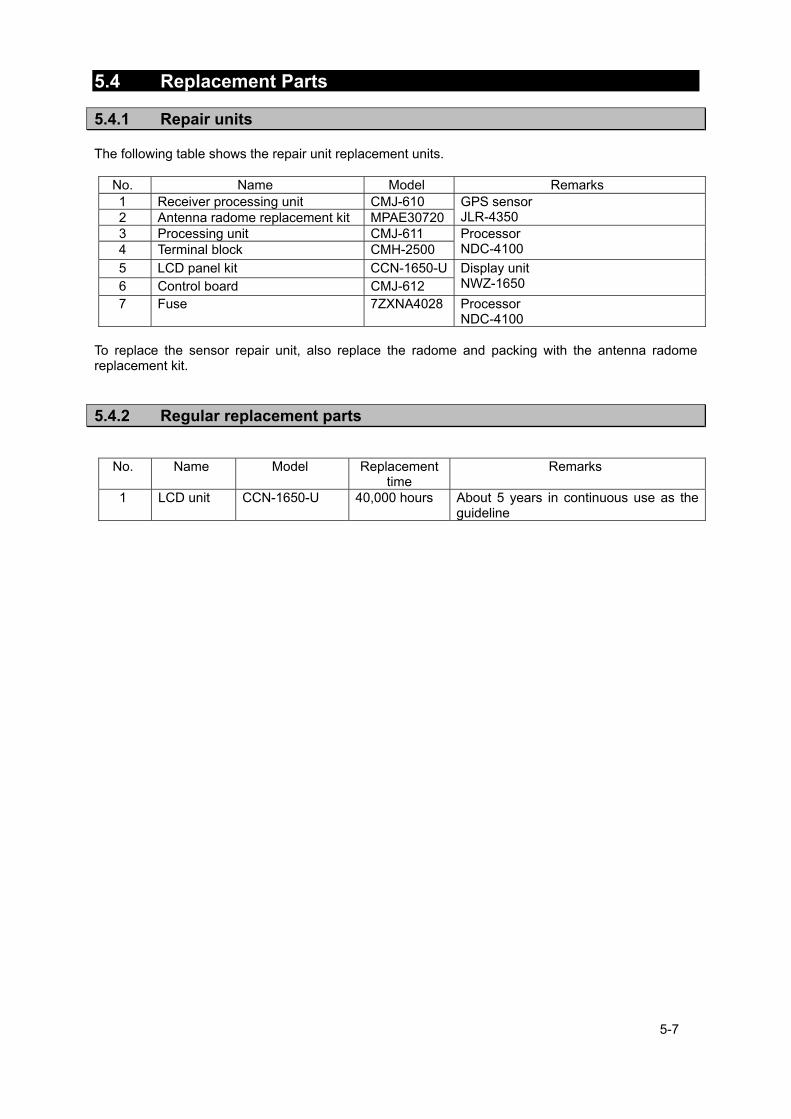
5-7
5.4 Replacement Parts
5.4.1 Repair units The following table shows the repair unit replacement units.
No. Name Model Remarks 1 Receiver processing unit CMJ-610 GPS sensor
JLR-4350 2 Antenna radome replacement kit MPAE30720 3 Processing unit CMJ-611 Processor
NDC-4100 4 Terminal block CMH-2500 5 LCD panel kit CCN-1650-U Display unit
NWZ-1650 6 Control board CMJ-612 7 Fuse 7ZXNA4028 Processor
NDC-4100 To replace the sensor repair unit, also replace the radome and packing with the antenna radome replacement kit.
5.4.2 Regular replacement parts
No. Name Model Replacement time
Remarks
1 LCD unit CCN-1650-U 40,000 hours About 5 years in continuous use as the guideline

5-8
6-1
Chapter 6 After-Sales Service
6.1 Warranty
● Specific periods may vary based on our warranty policies, but the standard warranty period
is one year from the date of purchase.
6.2 Repair parts stocking Period
● We keep functional repair parts for this equipment (parts necessary for the functioning of
this equipment) in stock for 10 years from the discontinuation of production.
6.3 When Requesting Service
When you think the equipment is not operating properly, please read "5.3 Troubleshooting" carefully, and inspect the equipment again. If the problem persists, stop using the equipment, and consult your dealer, or a JRC branch or affiliate.
● Repairs during the warranty period
Should a malfunction or failure occur when the equipment is operated according to the descriptions and instructions contained herein, it is repaired free of charge during the warranty period by JRC or another location specified by your dealer. However, any repair for failures resulting from misuse, negligence, or natural disasters, fire, or other Acts of God is charged.
● Repairs after the warranty period
Repairs to restore the proper equipment operation can be made at a specified rate with the user's consent. In this case, the equipment can either be sent to JRC or an affiliate, or on-ship repairs can be performed at a location specified by JRC or a sales affiliate. Repairs which cannot be performed on-board the ship needs to be performed in a repair plant.
● Information that needs to be provided when requesting service
• Name, model, production date, and serial number • Detailed description of the malfunction (alert number, etc.) • Name, address, and telephone number of your company or organization
6.4 Recommended Checks Inspection Equipment performance is subject to degradation due to age and change of component conditions over time. In addition to your own routine check, additional inspection and maintenance is recommended. Please consult with your dealer or one of our local offices. Note that this inspection and maintenance is not free of charge. If you have any other questions about after-sales service, please direct your inquiries to your dealer or nearest local office. A list of branches is provided at the end of the "Contact List".

6-2

7-1
Chapter 7 Disposal
When disposing of the used lithium battery, place insulating tape over the battery terminals, or otherwise insulate the battery. Failure to do so may result in heating, explosion, or fire due to a shorted battery.
7.1 Disposal of Equipment ● Observe all rules and regulations of the local authorities when disposing of this equipment.
7.2 Disposal of Used Batteries This equipment contains a lithium battery.
● When disposing of the used lithium battery, place insulating tape over the battery terminals, or otherwise insulate the battery. Dispose of the battery properly as directed by the local authorities. Consult your dealer, our sales office, or the local authorities for further details on disposal methods.
WARNING

7-2
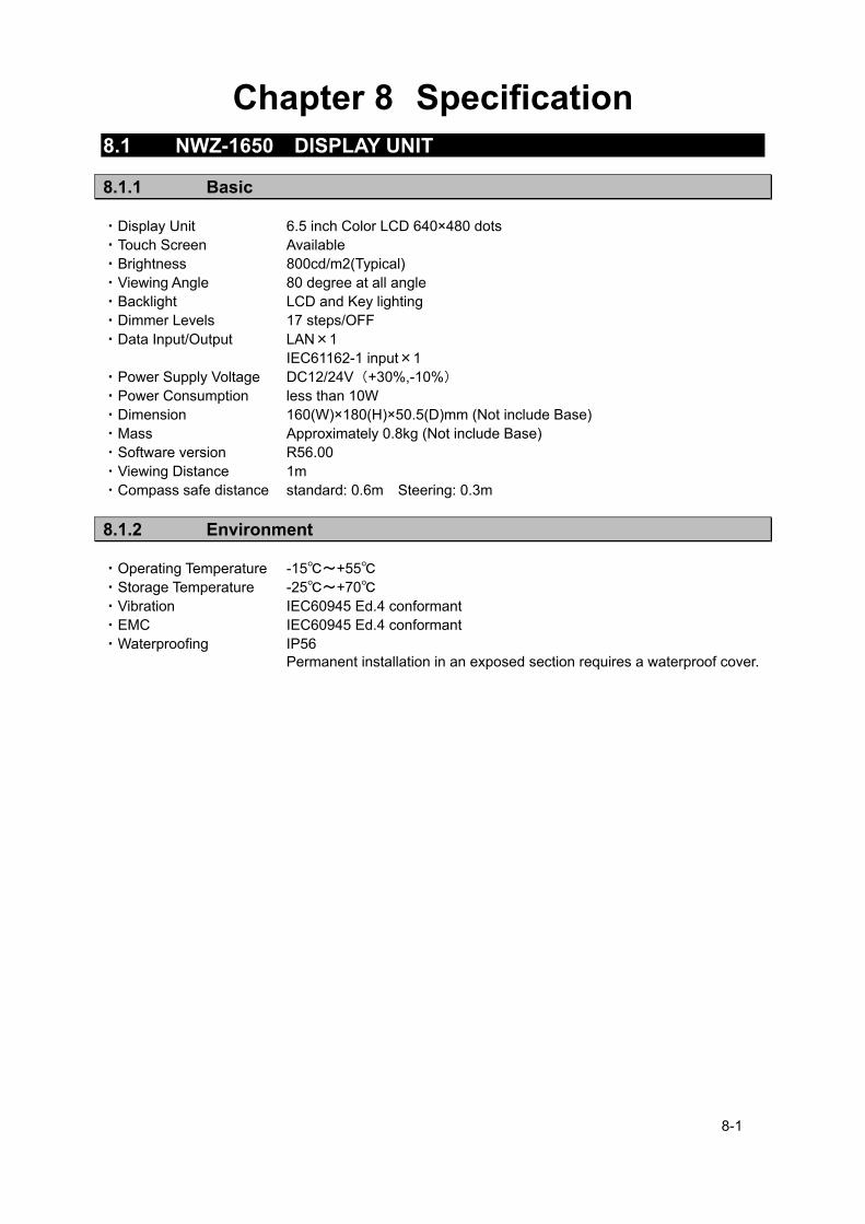
8-1
Chapter 8 Specification
8.1 NWZ-1650 DISPLAY UNIT
8.1.1 Basic ・Display Unit 6.5 inch Color LCD 640×480 dots ・Touch Screen Available ・Brightness 800cd/m2(Typical) ・Viewing Angle 80 degree at all angle ・Backlight LCD and Key lighting ・Dimmer Levels 17 steps/OFF ・Data Input/Output LAN×1 IEC61162-1 input×1 ・Power Supply Voltage DC12/24V(+30%,-10%) ・Power Consumption less than 10W ・Dimension 160(W)×180(H)×50.5(D)mm (Not include Base) ・Mass Approximately 0.8kg (Not include Base) ・Software version R56.00 ・Viewing Distance 1m ・Compass safe distance standard: 0.6m Steering: 0.3m
8.1.2 Environment ・Operating Temperature -15℃~+55℃ ・Storage Temperature -25℃~+70℃ ・Vibration IEC60945 Ed.4 conformant ・EMC IEC60945 Ed.4 conformant ・Waterproofing IP56 Permanent installation in an exposed section requires a waterproof cover.

8-2
8.2 JLR-4350 GPS Sensor
8.2.1 Basic ・GNSS GPS/GLONASS/BeiDou/SBAS/QZSS Can not receive GLONASS and BeiDou at the same time. ・Maximum Number of Tracked Satellites 22 satellites ・Accuracy GPS:5m 2DRMS (HDOP≦4 SA off) Beacon DGPS:4m 2DRMS SBAS:4m 2DRMS ・SBAS WAAS、MSAS、EGNOS ・QZSS QZSS(L1-C/A) No.1 Satellite only ・Geodetic datum Selection among 48 geodetic datum (Default:WGS-84) ・Power Supply Voltage DC12/24V (+30%,-10%) ・Power Consumption less than 1.0W ・Dimensions 134(Φ)mm×129(H)mm ・Mass Approximately 1.2kg (Include 15m cable) ・Software version R41.0 ・Compass safe distance standard: 1.0m Steering: 0.7m
8.2.2 Environment ・ Operating Temperature -25℃~+55℃ ・Storage Temperature -40℃~+70℃ ・Vibration IEC60945 ed.4 conformant ・EMC IEC60945 ed.4 conformant ・Waterproofing IP56

8-3
8.3 NDC-4100 Processor Unit
8.3.1 Basic
・Memories Waypoints 10000points maximum Event/Mark 1000points maximum (include MOB) Track 2000points maximum Route 100routes maximum
・Route plan 512 waypoints per one route ・Magnetic Variation Automatic or manual ・Navigation Calculation Grate circle or Rhumb line selectable ・Alert Arrival, Anchor, Boundary, XTD, No position fix, Speed, Trip, HDOP Temperature*, Depth* ・Plot Function Scale 0.2,0.5,1,2,5,10,20,50,100,200,300NM Interval 1~60min (1 sec) or 0.01~99.99NM (0.01NM) selectable ・Data Input/Output IEC61162-1 Output ×5, Input ×2 IEC61162-2 Output ×1, Input ×1 Buffer Unit: IEC61162-1 Output ×8 RS-232C Output ×1, Input ×1 IEC61162-450 LAN×2 ・Dry Contact Output ×4, Input ×1 ・Remote maintenance Available ・Unit Distance, Speed:NM,kn or km,km/h or mi,mi/h Height, Depth:m or ft or fm Temperature:℃ or ℉ ・Loran C/A Latitude and Longitude can be converted into the Loran time difference ・Language Japanese or English ・8ch Buffer Built-in ・2ch Select Switch Built-in ・Power Supply Voltage DC12/24V(+30%,-10%) ・Power Consumption 15W 以下 JLR-8600:less than 25W ・Dimensions 264(W)mm×100(H)mm×281(D)mm ・Mass Approximately 1.9kg ・Software version R60.0 ・Compass safe distance standard: 0.7m Steering: 0.4m *:External sensor must be connected
8.3.2 Environment ・Operating Temperature -15℃~+55℃ ・Storage Temperature -25℃~+70℃ ・Vibration IEC60945 ed.4 conformant ・EMC IEC60945 ed.4 conformant ・Waterproofing IP22

8-4
8.3.3 Interface 1) Serial Transmission
Channel Signal Input / Output Format IN/OUT 1 RS-422 Input IEC61162-2/NMEA
Output IEC61162-2/NMEA/JRC/SWITCH/SC-104 IN/OUT 2 RS-422 Input IEC61162-1/NMEA
Output IEC61162-1/NMEA/JRC/SWITCH/SC-104 IN/OUT 3 RS-422 Input IEC61162-1/NMEA
Output IEC61162-1/NMEA/JRC/SWITCH/SC-104 OUT 4 RS-422 Output IEC61162-1/NMEA/JRC/SWITCH/SC-104 OUT 5 RS-422 Output IEC61162-1/NMEA/JRC/SWITCH/SC-104 OUT 6 RS-422 Output IEC61162-1/NMEA/JRC/SWITCH/SC-104 BUFFER RS-422 Output IEC61162-1/NMEA RS-232C RS-232C Input IEC61162-1/NMEA
Output IEC61162-1/NMEA JLR-8600 does not support a SC-104 output format.
Note) The number of listener that can be connected to one output port is recommended to one port. 1-1) NMEA ・Specification NMEA0183 ・Version Ver1.5,2.1,2.3,4.0 ・Bit Rate 4800,9600,19200,38400bps ・Data Bit 8bit ・Parity None ・Start Bit 1bit ・Stop Bit 1bit ・Output Sentence GGA,RMC,GLL,VTG,GSA,GSV,DTM,GBS,GRS,GST,ZDA,GNS, ALR,APB,BOD,BWC,BWR,RMB,XTE,ZTG,AAM,RTE,WPL,ACK, ALC,ALF,HBT,ACN,HDT*,THS*,DBT*,DPT*,MTW*,CUR*,VBW*,VHW*, MWV*,VWR*,VWT* ・Output Interval 1s,2s,3s,4s,5s,6s,7s,8s,9s,OFF ・Input Sentence HDT,THS,DBT,DPT,MTW,CUR,VBW,VHW,ACK,WPL,RTE,ALR,ACN, ALC,ALF,HBT, MWV,VWR,VWT *External sensor must be connected Note) Some combinations of output sentence, bit rates, and output intervals may not be possible. 1-2) IEC ・Specification IEC61162-1 Ed.5 1-3)JRC ・Specification :JRC ・Bit Rate :1200bps ・Data Bit :8bit ・Parity :None ・Start Bit :1bit ・Stop Bit :2bit 2) Dry Contact
Channel Input / Output None
Contact 1,2,3,4 Output Alert, 200p/NM, 400p/NM, ACK Contact 5 Input ACK
3)LAN ・Specification :IEC61162-450/JRC ・Bit Rate :10/100Mbps ・Shared route :JRC Format ・Data output :NMEA,IEC
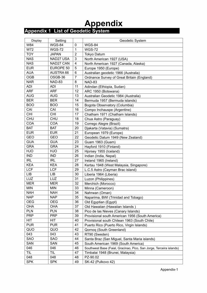
Appendix-1
Appendix Appendix 1 List of Geodetic System
Display Setting Geodetic System W84 WGS-84 0 WGS-84 W72 WGS-72 1 WGS-72 TOY JAPAN 2 Tokyo Datum NAS NAD27 USA 3 North American 1927 (USA) NAS NAD27 CAN 4 North American 1927 (Canada, Alaska) EUR EUROPE 50 5 Europe 1950 (Europe) AUA AUSTRA 66 6 Australian geodetic 1966 (Australia) OGB OSGB-36 7 Ordnance Survey of Great Britain (England) NAR NAD-83 8 NAD-83 ADI ADI 11 Adindan (Ethiopia, Sudan) ARF ARF 12 ARC 1950 (Botswana) AUG AUG 13 Australian Geodetic 1984 (Australia) BER BER 14 Bermuda 1957 (Bermuda islands) BOO BOO 15 Bogota Observatory (Columbia) CAI CAI 16 Compo Inchauspe (Argentine) CHI CHI 17 Chatham 1971 (Chatham Islands) CHU CHU 18 Chua Astro (Paraguay) COA COA 19 Corrego Alegre (Brazil) BAT BAT 20 Djakarta (Vatavia) (Sumatra) EUR EUR 21 European 1979 (Europe) GEO GEO 22 Geodetic Datum 1949 (New Zealand) GUA GUA 23 Guam 1963 (Guam) GRA GRA 24 Hayford 1910 (Finland) HJO HJO 25 Hjorsey 1955 (Iceland) IND IND 26 Indian (India, Nepal) IRL IRL 27 Ireland 1965 (Ireland) KEA KEA 28 Kertau 1948 (West Malaysia, Singapore) LCF LCF 29 L.C.5 Astro (Cayman Brac island) LIB LIB 30 Liberia 1964 (Liberia) LUZ LUZ 31 Luzon (Philippines) MER MER 32 Merchich (Morocco) MIN MIN 33 Minna (Cameroon) NAH NAH 34 Nahrwan (Oman) NAP NAP 35 Naparima, BWI (Trinidad and Tobago) OEG OEG 36 Old Egyptian (Egypt) OHA OHA 37 Old Hawaiian (Hawaiian Islands ) PLN PLN 38 Pico de las Nieves (Canary Islands) PRP PRP 39 Provisional south American 1956 (South America) HIT HIT 40 Provisional south Chilean 1963 (South Chile) PUR PUR 41 Puerto Rico (Puerto Rico, Virgin Islands) QUO QUO 42 Qornoq (South Greenland) 043 043 43 RT90 (Sweden) SAO SAO 44 Santa Braz (San Miguel, Santa Maria islands) SAN SAN 45 South American 1969 (South America) 046 046 46 Southwest Base (Faial, Gracinao, Pico, San Jorge, Terceira islands)
TIL TIL 47 Timbalai 1948 (Brunei, Malaysia) 048 048 48 PZ-90.02 SPK SPK 49 SK-42 (Pulkovo 42)
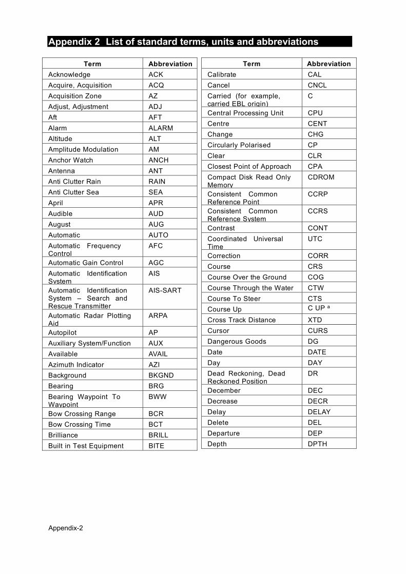
Appendix-2
Appendix 2 List of standard terms, units and abbreviations
Term Abbreviation
Acknowledge ACK
Acquire, Acquisition ACQ
Acquisition Zone AZ
Adjust, Adjustment ADJ
Aft AFT
Alarm ALARM
Altitude ALT
Amplitude Modulation AM
Anchor Watch ANCH
Antenna ANT
Anti Clutter Rain RAIN
Anti Clutter Sea SEA
April APR
Audible AUD
August AUG
Automatic AUTO
Automatic Frequency Control
AFC
Automatic Gain Control AGC
Automatic Identification System
AIS
Automatic Identification System – Search and Rescue Transmitter
AIS-SART
Automatic Radar Plotting Aid
ARPA
Autopilot AP
Auxiliary System/Function AUX
Available AVAIL
Azimuth Indicator AZI
Background BKGND
Bearing BRG
Bearing Waypoint To Waypoint
BWW
Bow Crossing Range BCR
Bow Crossing Time BCT
Brilliance BRILL
Built in Test Equipment BITE
Term Abbreviation
Calibrate CAL
Cancel CNCL
Carried (for example, carried EBL origin)
C
Central Processing Unit CPU
Centre CENT
Change CHG
Circularly Polarised CP
Clear CLR
Closest Point of Approach CPA
Compact Disk Read Only Memory
CDROM
Consistent Common Reference Point
CCRP
Consistent Common Reference System
CCRS
Contrast CONT
Coordinated Universal Time
UTC
Correction CORR
Course CRS
Course Over the Ground COG
Course Through the Water CTW
Course To Steer CTS
Course Up C UP a
Cross Track Distance XTD
Cursor CURS
Dangerous Goods DG
Date DATE
Day DAY
Dead Reckoning, Dead Reckoned Position
DR
December DEC
Decrease DECR
Delay DELAY
Delete DEL
Departure DEP
Depth DPTH
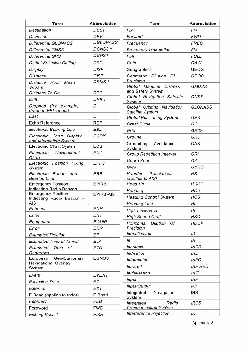
Appendix-3
Term Abbreviation
Destination DEST
Deviation DEV
Differential GLONASS DGLONASS a
Differential GNSS DGNSS a
Differential GPS DGPS a
Digital Selective Calling DSC
Display DISP
Distance DIST
Distance Root Mean Square
DRMS a
Distance To Go DTG
Drift DRIFT
Dropped (for example, dropped EBL origin)
D
East E
Echo Reference REF
Electronic Bearing Line EBL
Electronic Chart Display and Information System
ECDIS
Electronic Chart System ECS
Electronic Navigational Chart
ENC
Electronic Position Fixing System
EPFS
Electronic Range and Bearing Line
ERBL
Emergency Position Indicating Radio Beacon
EPIRB
Emergency Position Indicating Radio Beacon – AIS
EPIRB-AIS
Enhance ENH
Enter ENT
Equipment EQUIP
Error ERR
Estimated Position EP
Estimated Time of Arrival ETA
Estimated Time of Departure
ETD
European Geo-Stationary Navigational Overlay System
EGNOS
Event EVENT
Exclusion Zone EZ
External EXT
F-Band (applies to radar) F-Band
February FEB
Foreword FWD
Fishing Vessel FISH
Term Abbreviation
Fix FIX
Forward FWD
Frequency FREQ
Frequency Modulation FM
Full FULL
Gain GAIN
Geographics GEOG
Geometric Dilution Of Precision
GDOP
Global Maritime Distress and Safety System
GMDSS
Global Navigation Satellite System
GNSS
Global Orbiting Navigation Satellite System
GLONASS
Global Positioning System GPS
Great Circle GC
Grid GRID
Ground GND
Grounding Avoidance System
GAS
Group Repetition Interval GRI
Guard Zone GZ
Gyro GYRO
Harmful Substances (applies to AIS)
HS
Head Up H UP a
Heading HDG
Heading Control System HCS
Heading Line HL
High Frequency HF
High Speed Craft HSC
Horizontal Dilution Of Precision
HDOP
Identification ID
In IN
Increase INCR
Indication IND
Information INFO
Infrared INF RED
Initialisation INIT
Input INP
Input/Output I/O
Integrated Navigation System
INS
Integrated Radio Communication System
IRCS
Interference Rejection IR

Appendix-4
Term Abbreviation
Interswitch ISW
Interval INT
January JAN
July JUL
June JUN
Label LBL
Latitude LAT
Latitude/Longitude L/L
Leeway LWY
Limit LIM
Line Of Position LOP
Log LOG
Long Pulse LP
Long Range LR
Longitude LON
Loran LORAN
Lost Target LOST TGT
Low Frequency LF
Magnetic MAG
Man Overboard MOB
Manoeuvre MVR
Manual MAN
Map(s) MAP
March MAR
Maritime Mobile Services Identity number
MMSI
Maritime Pollutant (applies to AIS)
MP
Maritime Safety Information
MSI
Marker MKR
Master MSTR
Maximum MAX
May MAY
Medium Frequency MF
Medium Pulse MP
Menu MENU
Minimum MIN
Missing MISSING
Mute MUTE
Navigation NAV
Night NT
Normal NORM
North N
North Up N UP a
Term Abbreviation
Not Less Than NLT
Not More Than NMT
Not Under Command NUC
November NOV
October OCT
Off OFF
Officer On Watch OOW
Offset OFFSET
On ON
Out/Output OUT
Own Ship OS
Panel Illumination PANEL
Parallel Index Line PI
Past Positions PAST POSN
Passenger Vessel PASSV
Performance Monitor MON
Permanent PERM
Person Overboard POB
Personal Identification Number
PIN
Pilot Vessel PILOT
Port/Portside PORT
Position POSN
Positional Dilution Of Precision
PDOP
Power PWR
Predicted PRED
Predicted Area of Danger PAD
Predicted Point of Collision
PPC
Pulse Length PL
Pulse Modulation PM
Pulse Repetition Frequency
PRF
Pulse Repetition Rate PRR
Pulses Per Revolution PPR
Racon RACON
Radar RADAR
Radar Plotting RP
Radar Transponder TPR
Radius RAD
Rain RAIN
Range RNG
Range Rings RR
Raster Chart Display System
RCDS

Appendix-5
Term Abbreviation
Raster Navigational Chart RNC
Rate Of Turn ROT
Real-time Kinematic RTK
Receive RX a
Receiver RCDR
Receiver Autonomous Integrity Monitoring
RAIM
Reference REF
Relative REL b
Relative Motion RM
Revolutions per Minute RPM
Rhumb Line RL
Roll On/Roll Off Vessel RoRo
Root Mean Square RMS
Route ROUTE
Safety Contour SF CNT
Sailing Vessel SAIL
Satellite SAT
S-Band S-BAND
Scan to Scan SC/SC
Search And Rescue SAR
Search And Rescue Transponder
SART
Search And Rescue Vessel
SARV
Select SEL
September SEP
Sequence SEQ
Set (i.e., set and drift, or setting a value)
SET
Ship’s Time TIME
Short Pulse SP
Signal to Noise Ratio SNR
Simulation SIM c
Slave SLAVE
South S
Speed SPD
Speed and Distance Measuring Equipment
SDME
Speed Over the Ground SOG
Speed Through the Water STW
Stabilized STAB
Standby STBY
Starboard/Starboard Side STBD
Station STN
Symbol(s) SYM
Term Abbreviation
Synchronised/ Synchronous
SYNC
System Electronic Navigational Chart
SENC
Target TGT
Target Tracking TT
Test TEST
Time TIME
Time Difference TD
Time Dilution Of Precision TDOP
Time Of Arrival TOA
Time Of Departure TOD
Time to CPA TCPA
Time To Go TTG
Time to Wheel Over Line TWOL
Track TRK
Track Control System TCS
Tracking TRKG
Trail(s) TRAIL
Transmit and Receive TXRX a
Transceiver TCVR
Transferred Line Of Position
TPL
Transmit TX
Transmitter TMTR
Transmitting Heading Device
THD
Trial TRIAL c
Trigger Pulse TRIG
True T
True Motion TM
Tune TUNE
Ultrahigh Frequency UHF
Uninterruptible Power Supply
UPS
Universal Time, Coordinated
UTC
Universal Transverse Mercator
UTM
Unstabilised UNSTAB
Variable Range Marker VRM
Variation VAR
Vector VECT
Very High Frequency VHF
Very Low Frequency VLF
Vessel Aground GRND
Vessel at Anchor ANCH

Appendix-6
Term Abbreviation
Vessel Constrained by Draught
VCD
Vessel Engaged in Diving Operations
DIVE
Vessel Engaged in Dredging or Underwater Operations
DRG
Vessel Engaged in Towing Operations
TOW
Vessel Not Under Command
NUC
Vessel Restricted in Manoeuvrability
RIM
Vessel Traffic Service VTS
Vessel Underway Using Engine
UWE
Video VID
Term Abbreviation
Visual Display Unit VDU
Voyage VOY
Voyage Data Recorder VDR
Warning WARNING
Water WAT
Waypoint WPT
Waypoint Closure Velocity WCV
West W
Wheel Over Line WOL
Wheel Over Point WOP
Wheel Over Time WOT
World Geodetic System WGS
X-Band X-BAND

Appendix-7
Appendix 3 List of Symbols Symbol name Symbol graphic Own ship - simplified symbol
Double circle ◎
Velocity vector
Short-dashed line ◎
Past track
Small filled circle ◎
Waypoint
Circle ○
Route
Long-dashed line ○ ○
Event
Square with diagonal line
User cursor
Cross line

Appendix-8
Appendix 4 List of Default Setting Values MENU Sub Menu Sub Menu Sub Menu Default
DISPLAY
THEME DAY BEEP ON DAY SCREEN OFF NAV ON PLOT ON ANALOG ON HIGHWAY ON SAT INFO ON WPT INFO ON BEACON TEXT ON NAV ASSIST ON
VOYAGE
WPT WPT LIST - ROUTE ROUTE LIST - RUN - EVENTMARK EVENTMARK LIST - WPT COPY - ROUTE COPY - WPT DELETE - ROUTE DELETE
-
EVENT DELETE -
SHARED ROUTE SEND
CONNECT UNICAST IP 000.000.000.000 PORT 0 OUTPUT LAN1 FORMAT NMEA VER 1.5 DATA ALL WPT
ROUTE RECEIVE SOURCE IP 000.000.000.000
DEFAULT SETTINGS
WIDTH PORT(NM) 1.00 WIDTH STBD(NM) 1.00 ARRIVAL RADIUS(NM)
1.00
SPEED(kn) 10.00 SAIL RL SOG SMOOTHING(s) 0
ALERT
SYSTEM SET ON SOUND ON
ARRIVAL/ ANCHOR
SET OFF SOUND ON
XTD/ BOUNDARY
SET OFF SOUND ON
HDOP SET THRESHOLD 4 SOUND OFF
SPD SET OFF SOUND ON
TRIP SET OFF SOUND ON
EARLY COURSE CHANGE
SET OFF
SOUND ON
END OF TRACK SET OFF SOUND ON
ARRIVED AT WOL
SET OFF SOUND ON
ACTUAL COURSE CHANGE
SET OFF
SOUND ON

Appendix-9
MENU Sub Menu Sub Menu Sub Menu Range
ALERT
TEMP SET OFF SOUND ON
DPTH SET OFF SOUND ON
DGPS SET OFF SOUND OFF
BUFFER SET OFF SOUND ON
POWER SET ON SOUND ON
GNSS SETTING
SENSOR1
GNSS GPS MODE GPS FIX MODE AUTO ELV MASK 5 HDOP 10
SMOOTH
POSN SMOOTHING(s)
10
SPEED SMOOTHING(s)
10
COURSE SMOOTHING(s)
10
RAIM RAIM ACCURACY LEVEL(m)
100
DATUM WGS-84
INIT
QUADRANT - LAT - LON - ANT HEIGHT(m) - YEAR - MONTH - DAY - HOUR(hr) - MINUTE(min) -
DGPS AUTO
BEACON
AUTO - MANUAL 283.5kHz/25bps SEMI AUTO - MONITOR -
SBAS SAT SEARCH AUTO TYPE0 OFF RANGING OFF
STN LIST -
GNSS SETTING
SENSOR2 Same as SENSOR1
SYSTEM
DATE / TIME TIME DIFF +00:00 DATE DISP MMM DD,’YY TIME DISP(hr) 24hr
UNIT DIST / SPEED NM,kn HIGHT / DPTH m TEMP ℃
MAG CORR OFF LORAN OFF SENSOR SELECT
AUTO
LANGUAGE ENGLISH
VERSION
DISPLAY - PROCESSOR - SENSOR1 - SENSOR2 -
ALERT LIST
ALERT HISTORY
-
ACTIVE ALERT - LAN1 - LAN2 -

Appendix-10
MENU Sub Menu
Sub Menu Sub Menu Sub Menu Range
EQUIP
TYPE
TYPE1 / 2 DISPLAY
DISPLAY TYPE
MAIN
SFI GP0000
TYPE2/2 PROCESSOR
DEVICE No. No1 SFI GP0001 SENSOR1 GPS SENSOR2 OFF
DATA I/O
IN/OUT1
FORMAT NMEA BITRATE 4800 VERSION 2.3 TALKER GNSS
SENTENCE GGA,RMC,VTG,DTM,ZDA,APB,RMB
IN/OUT2 Same as IN/OUT1 IN/OUT3 Same as IN/OUT1 OUT4 Same as IN/OUT1 OUT5 Same as IN/OUT1 OUT6 Same as IN/OUT1
LAN
LAN1
DATA OUT
MULTICAST 239.192.000.004 60004 NMEA/2.3/GNSS GGA,RMC,VTG,DTM,ZDA,APB,RMB
RMS SEND
ON MULTICAST 239.192.000.005 60005
PRINTER
UNUSED OFF 000.000.000.000 9100
LAN2 DATA OUT Same as LAN1 RMS SEND Same as LAN1 PRINTER Same as LAN1
COMMON
ACTIVE ROUTE
OFF MULTICAST 239.000.096.001 6203
DATA ROUTE Same as ACTIVE ROUTE
MUTUAL
OFF MULTICAST 239.000.000.001 5101
CONTACT1 CONTACT OUT
SYSTEM
CONTACT2 CONTACT OUT
XTD
CONTACT3 CONTACT OUT
ACK
CONTACT4 CONTACT OUT
ARV
BUFFER
FORMAT NMEA BITRATE(bps) 4800 VERSION 2.3 TALKER GNSS
SENTENCE GGA,RMC,VTG,DTM,ZDA,APB,RMB

Appendix-11
MENU Sub Menu Sub Menu Sub Menu Sub Menu Range
EQUIP
DATA I/O
SENSOR
SENSOR1 PORT2(bps)
4800
SENSOR2 PORT2(bps)
4800
RS-232C
FORMAT NMEA BITRATE(bps) 4800 VERSION 2.3 TALKER GNSS
SENTENCE GGA,RMC,VTG,DTM,ZDA,APB,RMB
SWITCH
CONTROLL METHOD
MFD
SWITCH SELECTION
PROCESSOR No1.
DIMMER SETTINGS
DIMMER GROUP
1
DISPLAY OFF NCM-227 OFF DIMMER OFFSET
+000
DDC OFF GPS OFF GP DDC OFF
DIMMER CAL MIN
IP
DISPLAY
IP ADDRESS 172.018.001.169 MAC ADDRESS
-
SUBNET MASK
255.255.000.000
DEFAULT GATEWAY
000.000.000.000
PROCESSOR LAN 0
IP ADDRESS 172.018.001.163 MAC ADDRESS
-
SUBNET MASK
255.255.000.000
DEFAULT GATEWAY
172.016.060.001
PROCESSOR LAN 1
IP ADDRESS 172.016.060.163 MAC ADDRESS
-
SUBNET MASK
255.255.000.000
DEFAULT GATEWAY
172.016.060.001
PROCESSOR LAN 2
IP ADDRESS 172.017.060.163 MAC ADDRESS
-
SUBNET MASK
255.255.000.000
DEFAULT GATEWAY
172.016.060.001
CCRP
BEAM (m) 1.0 LENGTH(m) 1.0 CCRP(m) 0.0/0.0/0.0 SENSOR1 (m)
0.0/0.0/0.0
SENSOR2 (m)
0.0/0.0/0.0

Appendix-12
MENU Sub Menu Sub Menu Sub Menu Sub Menu Range
EQUIP
CTS
CLASS TANKER TRACKING GAIN
LOW
TRACKING HIGH
2880
TORACING MIDDLE
960
TRACKING LOW
270
TRACKING MULTIPLE
1.0
TRACKING COUNT A
6
TRACKING D GAIN
0.0
LOW SPEED COG
OUTPUT OFF
MAINTENANCE
DIAGNOSIS
DISPLAY - PROCESSOR - SENSOR1 - SENSOR2 -
MONITOR
DATA IN1 - DATA IN2 - DATA IN3 - RS-232C - SWITCH - LAN1 - LAN2 - SENSOR1 - SENSOR2 -
OPERATING TIME
OPERATING TIME(hr)
-
LCD TIME(hr) - RESET -
DEMO
DEMO TYPE STATIC START/ STOP START YEAR 00 MONTH 01 DAY 01 HOUR(hr) 00 MINUTE(min) 00 SECOND(s) 00 QUADRANT NE LAT 00°00.0000'N LON 00°00.0000'N SPEED(kn) 10.0 COURSE(°) 000.0 RADIUS(NM) 000.1 ROUTE 001
ALL SETTING VALUE
BACKUP INFO -
IMPORT/ EXPORT
MPORT/ EXPORT
PROCESSOR →DISPLAY
PROCESS BACKUP

Appendix-13
Appendix 5 Data Format
Output Sentence ・GGA – Global positioning system (GPS) fix data $--GGA, hhmmss.ss, llll.ll, a, yyyyy.yy, a, x, xx, x.x, x.x, M, x.x, M, x.x, xxxx*hh<CR><LF>
1 2 3 4 5 6 7 8 9 10 11 12 1:UTC of position 2:Latitude N/S 3:Longitude E/W 4:GPS quality indicator (see Note 1) 5:Number of satellites in use, 00-12, maybe different from the number in view 6:Horizontal dilution of precision 7:Antenna altitude above/below mean sea level (geoid) 8:Units of antenna altitude, m 9:Geoidal separation (see Note 3)
10:Units of geoidal separation,m 11:Age of differential GPS data (see Note 2) 12:Differential reference station ID, 0000-1023 NOTE 1 All GPS quality indicators in headings 1 through 8 are considered “valid”. The heading “0” is the only “invalid” indicator. The GPS quality indicator field should not be a null field. 0 = fix not available or invalid 1 = GPS SPS mode 2 = differential GPS, SPS mode 8 = Simulator mode
NOTE 2 Time in seconds since last SC104 type 1 or 9 update, null field when DGPS is not used.
NOTE 3 Geoidal separation: the difference between the WGS-84 earth ellipsoid surface and mean sea level (geoid) surface, “ – “ = mean sea level surface below the WGS-84 ellipsoid surface. ・RMC – Recommended minimum specific GNSS data $--RMC, hhmmss.ss, A, llll.ll,a, yyyyy.yy, a, x.x, x.x, xxxxxx, x.x,a, a, a*hh<CR><LF>
1 2 3 4 5 6 7 8 9 10 11 1213 1:UTC of position fix 2:Status (see Note 3) A = data valid V = navigation receiver warning 3:Latitude, N/S 4:Latitude, N/S 5:Longitude, E/W 6:Longitude, E/W 7:Speed over ground, knots 8:Course over ground, degrees true 9:Date: dd/mm/yy
10:Magnetic variation,degrees, E/W (see Note 1) 11:Magnetic variation,degrees, E/W (see Note 1) 12:Mode indicator(see Notes 2 and 3)
13:Navigational status (see Note 4) NOTE 1 E = Easterly variation subtracts from True course W = Westerly variation adds to True course
NOTE 2 Positioning system Mode Indicator: A = Autonomous. Satellite system used in non-differential mode in position fix; D = Differential. Satellite system used in differential mode in position fix; P = Precise. Satellite system used in precision mode. Precision mode is defined as: no deliberate degradation (such as selective availability) and higher resolution code (P-code) is used to compute position fix. P is also

Appendix-14
used for satellite system used in multi-frequency, SBAS or Precise Point Positioning (PPP) mode; S = Simulator mode.
NOTE 3 The positioning system mode indicator field supplements the positioning system status field, the status field should be set to V = Invalid for all values of indicator mode except for A= Autonomous and D = Differential. The positioning system mode indicator and status fields should not be null fields.
NOTE 4 The navigational status indicator is according to IEC 61108 requirements on ‘Navigational (or Failure) warnings and status indications’. This field should not be a NULL field and the character should take one of the following values: S = Safe when the estimated positioning accuracy (95 % confidence) is within the selected accuracy level corresponding to the actual navigation mode, and/or integrity is available and within the requirements for the actual navigation mode, and/or a new valid position has been calculated within 1 s for a conventional craft and 0,5 s for a high speed craft. C = Caution when integrity is not available. U = Unsafe when the estimated positioning accuracy (95 % confidence) is less than the selected accuracy level corresponding to the actual navigation mode, and/or integrity is available but exceeds the requirements for the actual navigation mode, and/or a new valid position has not been calculated within 1 s for a conventional craft and 0,5 s for a high speed craft. V = Navigational status not valid, equipment is not providing navigational status indication. ・GLL – Geographic position – Latitude/longitude $--GLL, llll.ll, a, yyyyy.yy, a, hhmmss.ss, A, a *hh<CR><LF>
1 2 3 4 5 6 7 1:Latitude, N/S 2:Latitude, N/S 3:Longitude, E/W 4:Longitude, E/W 5:UTC of position 6:Status (see Note 2) A=data valid V=data invalid 7:Mode indicator (see Notes 1 and 2)
NOTE 1 Positioning system mode indicator: D = Differential S = Simulator N = Data not valid
NOTE 2 The mode indicator field supplements the status field (field 6). The status field should be set to V = invalid for all values of operating mode except for A = Autonomous and D = Differential. The positioning system mode indicator and status fields should not be null fields. ・VTG – Course over ground and ground speed $--VTG, x.x, T, x.x, M, x.x, N, x.x, K,a*hh<CR><LF>
1 2 3 4 5 6 7 8 9 1:Course over ground, degrees true 2:Course over ground, degrees true 3:Course over ground, degrees magnetic 4:Course over ground, degrees magnetic 5:Speed over ground, knots (see Note 1) 6:Speed over ground, knots (see Note 1) 7:Speed over ground, km/h (see Note 1) 8:Speed over ground, km/h (see Note 1) 9:Mode indicator (see Note 2)
NOTE 1 The speed over the ground should always be non-negative.
NOTE 2 The mode indicator provides status information about the operation of the source device (such as positioning systems, velocity sensors, etc.) generating the sentence, and the validity of data being provided. The possible indications are as follows: A = Autonomous mode; D = Differential mode; P = Precise. Satellite system used in precision mode. Precision mode is defined as: no deliberate degradation (such as selective availability) and higher resolution code (P-code) is used to compute position fix. P is also used for

Appendix-15
satellite system used in multi-frequency, SBAS or Precise Point Positioning (PPP) mode; S = Simulator mode; N = Data not valid. The mode indicator field should not be a null field. ・GSA – GNSS DOP and active satellites $--GSA, a, x, xx,xx,xx,xx,xx,xx,xx,xx,xx,xx,xx,xx,x.x,x.x,x.x,h*hh<CR><LF>
1 2 3 4 5 6 7 1:Mode: M = manual, forced to operate in 2D or 3D mode
A = automatic, allowed to automatically switch 2D/3D 2:Mode: 1 = fix not available, 2 = 2D, 3 = 3D 3:ID numbers (see Note 1) of satellites used in solution 4:PDOP 5:HDOP 6:VDOP 7:GNSS System ID (see Note 2)
NOTE 1 Satellite ID numbers. To avoid possible confusion caused by repetition of satellite ID numbers when using multiple satellite systems, the following convention has been adopted. a) GPS satellites are identified by their PRN numbers, which range from 1 to 32. b) The numbers 33 to 64 are reserved for WAAS satellites. The WAAS system PRN numbers are 120 to 138. The offset from WAAS SV ID to WAAS PRN number is 87. A WAAS PRN number of 120 minus 87 yields the SV ID of 33. The addition of 87 to the SV ID yields the WAAS PRN number. c) The numbers 65 to 96 are reserved for GLONASS satellites. GLONASS satellites are identified by 64+ satellite slot numbers. The slot numbers are 1 through 24 for the full GLONASS constellation of 24 satellites, thus giving a range of 65 through 88. The numbers 89 through 96 are available if slot numbers above 24 are allocated to on-orbit spares.
NOTE 2 GNSS System ID identifies the GNSS System ID according to the Table below. ・GSV – GNSS satellites in view $--GSV, x, x, xx, xx, xx, xxx, xx.............., xx, xx, xxx, xx, h*hh<CR><LF>
1 2 3 4 5 6 7 8 9 10 1:Total number of messages (see Note 1), 1 to 9 2:Message number (see Note 1), 1 to 9 3:Total number of satellites in view 4:Satellite ID number (see Note 3) 5:Elevation, degrees, 90° maximum 6:Azimuth, degrees true, 000 to 359 7:SNR (C/No) 00-99 dB-Hz, null when not tracking 8:Second and third SVs (see Note 2) 9:Fourth SV (see Note 2)
10:Signal ID (see Note 4) NOTE 1 Satellite information may require the transmission of multiple sentences all containing identical field formats when sending a complete message. The first field specifies the total number of sentences, minimum value 1. The second field identifies the order of this sentence (sentence number), minimum value 1. For efficiency it is recommended that null fields be used in the additional sentences when the data is unchanged from the first sentence.
NOTE 2 A variable number of "Satellite ID-Elevation-Azimuth-SNR" sets are allowed up to a maximum of four sets per sentence. Null fields are required for unused sets when less than four sets are transmitted.
NOTE 3 Satellite ID numbers. To avoid possible confusion caused by repetition of satellite ID numbers when using multiple satellite systems, the following convention has been adopted: a) GPS satellites are identified by their PRN numbers, which range from 1 to 32. b) The numbers 33 to 64 are reserved for WAAS satellites. The WAAS system PRN numbers are 120 to 138. The offset from WAAS SV ID to WAAS PRN number is 87. A WAAS PRN number of 120 minus 87 yields the SV ID of 33. The addition of 87 to the SV ID yields the WAAS PRN number. c) The numbers 65 to 96 are reserved for GLONASS satellites. GLONASS satellites are identified by 64+satellite slot number. The slot numbers are 1 through 24 for the full GLONASS constellation of 24 satellites, this gives a range of 65 through 88. The numbers 89 through 96 are available if slot numbers

Appendix-16
above 24 are allocated to on-orbit spares.
NOTE 4 Signal ID see Table below. ・DTM – Datum reference $--DTM,ccc,a,x.x,a,x.x,a, x.x,ccc*hh<CR><LF>
1 2 3 4 5 6 7 8 1:L o cal datum(see Note 1)
WGS84 = W84 / WGS72 = W72 / SGS85 = S85 / PE90 = P90 User defined = 999 / IHO datum code (see Note 4)
2:Local datum subdivision code (see Note 2) 3:Lat offset, min, N/S (see Note 3) 4:Lat offset, min, N/S (see Note 3) 5:Lon offset, min, E/W (see Note 3) 6:Lon offset, min, E/W (see Note 3) 7:Altitude offset, m (see Note 3) 8:Reference datum (WGS84 = W84 / WGS72 = W72 / SGS85 = S85 / PE90 = P90)
NOTE 1 Three character alpha code for local datum. If not one of the listed earth-centred datums, or 999 for user defined datums, use IHO datum code from International Hydrographic Organisation Publication S-60, Appendices B and C. Null field if unknown. This field should be set to 999 when manual offsets are entered and in use by the position fixing device.
NOTE 2 One character subdivision datum code when available or user defined reference character for user defined datums, null field otherwise. Subdivision character from IHO Publication S-60, Appendices B and C.
NOTE 3 Latitude and longitude offsets are positive numbers, the altitude offset may be negative. Offsets change with position: position in the local datum is offset from the position in the reference datum in the directions indicated:
Plocal datum = Pref datum + offset When field 1 contains a value of 999, these fields may not be null, and should contain the manually entered or user defined offsets.
NOTE 4 Users should be aware that chart transformations based on IHO S60 parameters may result in significant positional errors when applied to chart data. ・GBS – GNSS satellite fault detection $--GBS, hhmmss.ss, x.x, x.x, x.x, xx, x.x, x.x, x.x, h, h *hh <CR><LF>
1 2 3 4 5 6 7 8 9 10 1:UTC time of the GGA or GNS fix associated with this sentence 2:Expected error in latitude (see Note 1) 3:Expected error in longitude (see Note 1) 4:Expected error in altitude (see Note 1) 5:ID number (see Note 2) of most likely failed satellite 6:Probability of missed detection for most likely failed satellite 7:Estimate of bias on most likely failed satellite(in metres) 8:Standard deviation of bias estimate 9:GNSS System ID (see Note 3)
10:GNSS Signal ID (see Note 4) NOTE 1 Expected error in metres due to bias, with noise = 0.
NOTE 2 Satellite ID numbers. To avoid possible confusion caused by repetition of satellite ID numbers when using multiple satellite systems, the following convention has been adopted (these legacy systems remain in effect for new systems see NOTE 3): a) GPS satellites are identified by their PRN numbers, which range from 1 to 32. b) The numbers 33-64 are reserved for WAAS satellites. The WAAS system PRN numbers are 120-138. The offset from WAAS SV ID to WAAS PRN number is 87. A WAAS PRN number of 120 minus 87 yields the SV ID of 33. The addition of 87 to the SV ID yields the WAAS PRN number. c) The numbers 65-96 are reserved for GLONASS satellites. GLONASS satellites are identified by 64+ satellite slot number. The slot numbers are 1 through 24 for the full GLONASS constellation of 24 satellites; this gives a range of 65 through 88. The numbers 89 through 96 are available if slot numbers above 24 are allocated to on-orbit spares.

Appendix-17
NOTE 3 System ID identifies the GNSS System ID according to the Table below. Note that legacy numbering system as above should remain in effect.
NOTE 4 GNSS Signal ID identifies the GNSS Signal ID according to the Table below. ・GRS – GNSS range residuals $--GRS, hhmmss.ss,x,x.x,x.x,x.x,x.x,x.x,x.x,x.x,x.x,x.x,x.x,x.x,x.x,h,h *hh<CR><LF>
1 2 3 4 5 1:UTC time of the GGA or GNS fix associated with this sentence 2:Mode: 0 = residuals were used to calculate the position given in the matching GGA or GNS
sentence 1 = residuals were re-computed after the GGA or GNS position was computed
3:Range residuals for satellites used in the navigation solution (see Notes 1 and 2) Order should match order of satellite ID (see Note 3) numbers in GSA. When GRS is used, GSA and GSV are generally required. Null for unused fields
4:GNSS System ID (see Note 3) 5:Signal ID (see Note 4)
NOTE 1 If the range residual exceeds ±99,9 m, then the decimal part is dropped, resulting in an integer (–103,7 becomes –103). The maximum value for this field is ±999.
NOTE 2 The sense or sign of the range residual is determined by the order of parameters used in the calculation. The expected order is as follows: range residual = calculated range - measured range.
NOTE 3 When multiple GRS sentences are being sent then their order of transmission should match the order of corresponding GSA sentences. Listeners should keep track of pairs of GSA and GRS sentences and discard data if pairs are incomplete.
NOTE 4 Signal ID identifies the actual ranging signal according to the Table below.
NOTE 5 System ID, see Table below. ・GST – GNSS pseudorange noise statistics $--GST, hhmmss.ss, x.x, x.x, x.x, x.x, x.x, x.x, x.x*hh<CR><LF>
1 2 3 4 5 6 7 8 1:UTC time of the GGA or GNS fix associated with this sentence 2:RMS value of the standard deviation of the range inputs to the
navigation process. Range inputs include pseudoranges and DGPS corrections 3:Standard deviation of semi-major axis of error ellipse (m) 4:Standard deviation of semi-minor axis of error ellipse (m) 5:Orientation of semi-major axis of error ellipse (degrees from true north) 6:Standard deviation of latitude error (m) 7:Standard deviation of longitude error (m) 8:Standard deviation of altitude error (m)
・ZDA – Time and date $--ZDA, hhmmss.ss, xx, xx, xxxx, xx, xx*hh<CR><LF>
1 2 3 4 5 6 1:UTC 2:Day, 01 to 31 (UTC) 3:Month, 01 to 12 (UTC) 4:Year (UTC) 5:Local zone hours(see Note), 00 h to ±13 h 6:Local zone minutes (see Note), 00 to +59
NOTE Local time zone is the magnitude of hours plus the magnitude of minutes added, with the sign of local zone

Appendix-18
hours, to local time to obtain UTC. Local zone is generally negative for East longitudes with local exceptions near the international date line. Example: At Chatham Is. (New Zealand) at 1230 (noon) local time on June 10, 1995: $GPZDA,234500,09,06,1995,-12,45*6C<CR><LF> In the Cook Islands at 1500 local time on June 10, 1995: $GPZDA,013000,11,06,1995,10,30*4A<CR><LF> ・GNS – GNSS fix data $-- GNS, hhmmss.ss, llll.ll, a, yyyyy.yy, a, c--c,xx,x.x,x.x,x.x,x.x,x.x,a *hh<CR><LF>
1 2 3 4 5 6 7 8 9 10 11 12 13 1:UTC of position 2:Latitude, N/S 3:Latitude, N/S 4:Longitude, E/W 5:Longitude, E/W 6:Mode indicator (see Note 1) 7:Total number of satellites in use, 00-99 8:HDOP (see Note 3) 9:Antenna altitude, m, re: mean-sea-level (geoid)
10:Geoidal separation, m (see Note 4) 11:Age of differential data (see Note 2) 12:Differential reference station ID (see Note 2) 13:Navigational status indicator (see Note 5) NOTE 1 Mode indicator. A variable length valid character field type with the first three characters currently defined. The first character indicates the use of GPS satellites, the second character indicates the use of GLONASS satellites and the third indicate the use of Galileo satellites. If another satellite system is added to the standard, the mode indicator will be extended to four characters, new satellite systems should always be added on the right, so the order of characters in the mode indicator is: GPS, GLONASS, Galileo, other satellite systems in the future. The characters should take one of the following values: A = Autonomous. Satellite system used in non-differential mode in position fix D = Differential. Satellite system used in differential mode in position fix N = No fix. Satellite system not used in position fix, or fix not valid P = Precise. Satellite system used in precision mode. Precision mode is defined as: no deliberate degradation (such as selective availability) and higher resolution code (P-code) is used to compute position fix. P is also used for satellite system used in multi-frequency, SBAS or Precise Point Positioning (PPP) mode S = Simulator mode The mode indicator should not be a null field.
NOTE 2 Age of differential data and Differential Reference Station ID: a) When the talker is GN and more than one of the satellite systems are used in differential mode, then the “Age of differential data” and “Differential reference station ID” fields should be null. In this case, the “Age of differential data” and “Differential reference station ID” fields should be provided in following GNS sentences with talker IDs of GP, GL, etc. These following GNS messages should have the latitude, N/S, longitude, E/W, altitude, geoidal separation, mode, and HDOP fields null. This indicates to the listener that the field is supporting a previous $GNGNS sentence with the same time tag. The “Number of satellites” field may be used in these following sentences to denote the number of satellites used from that satellite system. Example: A combined GPS/GLONASS receiver using only GPS differential corrections has the following GNS sentence sent. $GNGNS,122310.2,3722.425671,N,12258.856215,W ,DA,14,0.9,1005.543,6.5,5.2,23*59<CR><LF> Example: A combined GPS/GLONASS receiver using both GPS differential corrections and GLONASS differential corrections may have the following three GNS sentences sent in a group. $GNGNS,122310.2,3722.425671,N,12258.856215,W ,DD,14,0.9,1005.543,6.5,,*74<CR><LF> $GPGNS,122310.2, , , , , ,7, , , ,5.2,23*4D<CR><LF> $GLGNS,122310.2, , , , , ,7, , , ,3.0,23*55<CR><LF> The Differential Reference station ID may be the same or different for the different satellite systems. b) Age of Differential Data For GPS Differential Data: This value is the average age of the most recent differential corrections in use. When only RTCM SC104 Type 1 corrections are used, the age is that of the most recent Type 1 correction. When RTCM SC104 Type 9 corrections are used solely, or in combination with Type 1 corrections, the age is the average of the most recent corrections for the satellites used. Null field when Differential GPS is not used. NOTE 3 HDOP calculated using all the satellites (GPS, GLONASS, Galileo and any future satellites) used in computing the solution reported in each GNS sentence.
NOTE 4 Geoidal Separation: the difference between the earth ellipsoid surface and mean-sea-level (geoid) surface defined by the reference datum used in the position solution, “-” = mean-sea-level surface below ellipsoid. The reference datum may be specified in the DTM sentence.

Appendix-19
NOTE 5 The navigational status indicator is according to IEC 61108 requirements on ‘Navigational (or Failure) warnings and status indications’. This field should not be a NULL field and the character should take one of the following values: S = Safe when the estimated positioning accuracy (95 % confidence) is within the selected accuracy level corresponding to the actual navigation mode, and integrity is available and within the requirements for the actual navigation mode, and a new valid position has been calculated within 1 s for a conventional craft and 0,5 s for a high speed craft C = Caution when integrity is not available U = Unsafe when the estimated positioning accuracy (95 % confidence) is less than the selected accuracy level corresponding to the actual navigation mode, and/or integrity is available but exceeds the requirements for the actual navigation mode, and/or a new valid position has not been calculated within 1 s for a conventional craft and 0,5 s for a high speed craft V = Navigational status not valid, equipment is not providing navigational status indication. ・MSS – MSK receiver signal status $--MSS,x.x,x.x,x.x,x.x,x*hh<CR><LF>
1 2 3 4 5 1:Signal strength (SS), dB/1 mV/m 2:Signal-to-noise ratio (SNR), dB 3:Beacon frequency, 283,5 kHz to 325,0 kHz 4:Beacon bit rate (25, 50, 100, 200) bits/s 5:Channel number (see Note)
NOTE Set equal to "1" or null for single channel receivers. ・ALR – Set alarm state $--ALR,hhmmss.ss,xxx,A, A,c--c*hh<CR><LF>
1 2 3 4 5 1:Time of alarm condition change, UTC 2:Unique alarm number (identifier) at alarm source 3:Alarm condition (A = threshold exceeded, V = not exceeded) 4:Alarm’s acknowledge state, A = acknowledged / V = unacknowledged 5:Alarm’s description text
・APB – Heading/track controller (autopilot) sentence B $--APB, A, A, x.x, a, N, A, A, x.x, a, c--c, x.x, a, x.x, a, a*hh<CR><LF>
1 2 3 4 5 6 7 8 9 10 11 12 13 14 15 1:Status: A = Data valid V = LORAN-C blink or SNR warning (see Note 2)
V = general warning flag for other navigation systems when a reliable fix is not available 2:Status: A = OK or not used V = LORAN-C cycle lock warning flag (see Note 2) 3:Magnitude of XTE (cross-track-error) 4:Direction to steer, L/R 5:XTE units, nautical miles 6:Status: A = arrival circle entered V = arrival circle not passed 7:Status: A = perpendicular passed at waypoint
V = perpendicular not entered 8:Bearing origin to destination, M/T 9:Bearing origin to destination, M/T
10:Destination waypoint ID 11:Bearing, present position to destination, magnetic or true 12:Bearing, present position to destination, magnetic or true 13:Heading to steer to destination waypoint, magnetic or true 14:Heading to steer to destination waypoint, magnetic or true

Appendix-20
15:Mode indicator (see Notes 1 and 2) NOTE 1 Positioning system mode indicator: A = Autonomous mode; D = Differential mode; S = Simulator mode; N = Data not valid.
NOTE 2 The positioning system mode indicator field supplements the positioning system status fields (fields 1 and 2), the status fields should be set to V = invalid for all values of mode indicator except for A = Autonomous and D = Differential. The positioning system mode indicator should not be null fields. ・BOD – Bearing origin to destination $--BOD, x.x, T, x.x, M, c--c, c--c*hh<CR><LF>
1 2 3 4 5 6 1:Bearing, degrees true 2:Bearing, degrees true 3:Bearing, degrees magnetic 4:Bearing, degrees magnetic 5:Destination waypoint ID 6:Origin waypoint ID
・BWC – Bearing and distance to waypoint – Great circle $--BWC, hhmmss.ss, llll.ll, a, yyyyy.yy, a, x.x, T, x.x, M, x.x, N, c--c, a*hh<CR><LF>
1 2 3 4 5 6 7 8 9 10 11 12 13 1:UTC of observation 2:Waypoint latitude, N/S 3:Waypoint latitude, N/S 4:Waypoint longitude, E/W 5:Waypoint longitude, E/W 6:Bearing, degrees true 7:Bearing, degrees true 8:Bearing, degrees magnetic 9:Bearing, degrees magnetic
10:Distance, nautical miles 11:Distance, nautical miles 12:Waypoint ID 13:Mode indicator (see Note) NOTE Positioning system mode indicator: A = Autonomous mode; D = Differential mode; S = Simulator mode; N = Data not valid. The mode indicator field should not be a null field.
・BWR – Bearing and distance to waypoint – Rhumb line $--BWR, hhmmss.ss, llll.ll, a, yyyyy.yy, a, x.x, T, x.x, M, x.x, N, c--c, a*hh<CR><LF>
1 2 3 4 5 6 7 8 9 10 11 12 13 1:UTC of observation 2:Waypoint latitude, N/S 3:Waypoint latitude, N/S 4:Waypoint longitude, E/W 5:Waypoint longitude, E/W

Appendix-21
6:Bearing, degrees true 7:Bearing, degrees true 8:Bearing, degrees magnetic 9:Bearing, degrees magnetic
10:Distance, nautical miles 11:Distance, nautical miles 12:Waypoint ID 13:Mode indicator (see Note) NOTE Positioning system mode indicator: A = Autonomous mode; D = Differential mode; S = Simulator mode; N = Data not valid. The mode indicator field should not be a null field. ・RMB – Recommended minimum navigation information $--RMB, A, x.x, a, c--c, c--c, llll.ll, a, yyyyy.yy,a,x.x, x.x, x.x, A, a *hh<CR><LF>
1 2 3 4 5 6 7 8 9 10 11 12 13 14 1:Status (see Note 4): A = data valid
V = navigation receiver warning 2:Cross track error (see Note 2), nautical miles 3:Direction to steer L/R 4:Origin waypoint ID 5:Destination waypoint ID 6:Destination waypoint latitude, N/S 7:Destination waypoint latitude, N/S 8:Destination waypoint longitude, E/W 9:Destination waypoint longitude, E/W
10:Range to destination, nautical miles (see Note 1) 11:Bearing to destination, degreestrue 12:Destination closing velocity, knots 13:Arrival status
A = arrival circle, entered or perpendicular passed V = not entered or passed
14:Mode indicator (see Notes 3 and 4) NOTE 1 If range to destination exceeds 999,9 nautical miles, display 999,9.
NOTE 2 If cross track error exceeds 9,99 nautical miles, display 9,99.
NOTE 3 Positioning system mode indicator: A = Autonomous mode; D = Differential mode; S = Simulator mode; N = Data not valid.
NOTE 4 The positioning system mode indicator field supplements the status field (field No. 1) which should be set to V = invalid for all values of Mode indicator except for A = Autonomous and D = Differential. The positioning system mode indicator and status fields should not be null fields. ・XTE – Cross-track error, measured $--XTE,A,A,x.x,a,N,a*hh<CR><LF
1 2 3 4 5 6 1:Status (see Note 2) A = data valid, V = LORAN – C blink or SNR warning
V = general warning flag for other navigation systems when a reliable fix is not available
2:Status: A = data valid V = Loran-C cycle lock warning flag

Appendix-22
3:Magnitude of cross-track error 4:Direction to steer, L/R 5:Units, nautical miles 6:Mode indicator (see Notes 1 and 2)
NOTE 1 Positioning system mode indicator:
A = Autonomous mode; D = Differential mode; S = Simulator mode; N = Data not valid.
NOTE 2 The positioning system mode indicator field supplements the positioning system status fields (fields 1 and 2); the status fields should be set to V = invalid for all values of indicator mode except for A = Autonomous and D = Differential. The positioning system mode indicator and status fields should not be null fields. ・ZTG – UTC and time to destination waypoint $--ZTG, hhmmss.ss, hhmmss.ss, c--c*hh<CR><LF>
1 2 3 1:UTC of observation 2:Time-to-go, hh = 00 to 99 3:Destination waypoint ID
・AAM – Waypoint arrival alarm $--AAM, A, A,x.x, N, c--c*hh<CR><LF> 1:Status: A = arrival circle entered; V = not entered 2:Status: A = perpendicular passed at waypoint; V = not passed 3:Arrival circle radius 4:Units of radius, nautical miles 5:Waypoint ID
・RTE – Routes $--RTE, x.x, x.x, a, c--c, c--c,...... c--c*hh<CR><LF>
1 2 3 4 5 6 7 8 1:Total number of sentences being transmitted (see Note 2) 2:Sentence number (see Note 2) 3:Message mode: c = complete route, all waypoints
w = working route, first listed waypoint is "FROM", second is "TO" and remaining are rest of route
4:Route identifier 5:Waypoint identifier 6:Additional waypoint identifiers (see Note 1)
7:Additional waypoint identifiers (see Note 1) 8:Waypoint "n" identifier (see Note 1) NOTE 1 A variable number of waypoint identifiers, up to "n", may be included within the limits of allowed sentence length. As there is no specified number of waypoints, null fields are not required for waypoint identifier fields.
NOTE 2 A single route may require the transmission of multiple sentences, all containing identical field formats when sending a complex message. The first field specifies the number of sentences, minimum value = 1. The second field identifies the order of this sentence (sentence number), minimum value = 1. For efficiency, it is permitted that null fields be used in the additional sentences when the data is unchanged from the first sentence. (Note that this practice can lead to the incorrect assembly of sentences if there is a high risk of loss of sentence.)

Appendix-23
・WPL – Waypoint location $--WPL, llll.ll, a, yyyyy.yy, a, c--c*hh<CR><LF>
1 2 3 4 5 1:Waypoint latitude, N/S 2:Waypoint latitude, N/S 3:Waypoint longitude, E/W 4:Waypoint longitude, E/W 5:Waypoint identifier
・ACK – Acknowledge alarm $--ACK,xxx*hh<CR><LF>
1 1:Unique alarm number (identifier) at alarm source ・HDT – Heading true $--HDT, x.x, T*hh<CR><LF>
1 2 1:Heading, degrees true 2:Heading, degrees true
・THS – True heading and status $--THS,x.x,a*hh<CR><LF>
1 2 1:Heading, degrees true 2:Mode indicator (see Note)
NOTE Mode indicator. This field should not be null. A = Autonomous S = Simulator mode V = Data not valid (including standby) ・DBT – Depth below transducer $--DBT, x.x, f, x.x, M, x.x, F*hh<CR><LF>
1 2 3 4 5 6 1:Water depth, feet 2:Water depth, feet 3:Water depth, m 4:Water depth, m 5:Water depth, fathoms 6:Water depth, fathoms

Appendix-24
・DPT – Depth $--DPT, x.x, x.x, x.x*hh<CR><LF>
1 2 3 1:Water depth relative to the transducer, in metres 2:Offset from transducer, in metres (see Notes 1 and 2) 3:Maximum range scale in use
NOTE 1 “positive” = distance from transducer to water line; “-“ = distance from transducer to keel.
NOTE 2 For IEC applications, the offset should always be applied so as to provide depth relative to the keel. ・MTW – Water temperature $-- MTW, x.x, C*hh<CR><LF>
1 2 1:Temperature, degrees C 2:Temperature, degrees C
・CUR – Water current layer – Multi-layer water current data $--CUR,A,x,x.x,x.x,x.x,a,x.x,x.x,x.x,a,a*hh<CR LF>
1 2 3 4 5 6 7 8 9 1011 1:Validity of the data, A = Valid, V = not valid 2:Data set number, 0 to 9 (see Note 1) 3:Layer number (see Note 2) 4:Current depth in metres 5:Current direction in degrees 6:Direction reference in use, True/Relative T/R
7:Current speed in knots 8:Reference layer depth in metres (see Note 3) 9:Heading 10:Heading reference in use, True/Magnetic T/M 11:Speed reference (see Note 4)
B: Bottom track W: Water track P: Positioning system
NOTE 1 The data set number is used to identify multiple sets of current data produced in one measurement instance. Each measurement instance may result in more than one sentence containing current data measurements at different layers, all with the same data set number. This is used to avoid the data measured in another instance to be accepted as one set of data.
NOTE 2 The layer number identifies which layer the current data measurements were made from. The number of layers that can be measured varies by device. The typical number is between 3 and 32, though many more are possible.
NOTE 3 The current of each layer is measured according to this reference layer, when the speed reference field is set to “water track”, or the depth is too deep for bottom track.
NOTE 4 “Speed reference” identifies the method of ship speed used for measuring the current speed.

Appendix-25
・VBW – Dual ground/water speed $--VBW, x.x, x.x, A, x.x, x.x, A, x.x, A, x.x, A*hh<CR><LF>
1 2 3 4 5 6 7 8 9 10 1:Longitudinal water speed (see Note 1), knots 2:Transverse water speed (see Note 1), knots 3:Status (see Note 2): water speed, A = data valid, V = data invalid 4:Longitudinal ground speed (see Note 1), knots 5:Transverse ground speed (see Note 1), knots 6:Status (see Note 2), ground speed, A = data valid, V = data invalid
7:Stern transverse water speed (see Note 1), knots 8:Status (see Note 2): stern water speed, A = data valid, V = data invalid 9:Stern transverse ground speed (see Note 1), knots 10:Status (see Note 2): stern ground speed, A = data valid, V = data invalid NOTE 1 Transverse speed: "-" = port,
Longitudinal speed: "-" = astern.
NOTE 2 The status field should not be a null field. ・VHW – Water speed and heading $--VHW, x.x, T, x.x, M, x.x, N, x.x, K*hh<CR><LF>
1 2 3 4 5 6 7 8 1:Heading, degrees true 2:Heading, degrees true 3:Heading, degrees magnetic 4:Heading, degrees magnetic 5:Speed, knots 6:Speed, knots
7:Speed, km/h 8:Speed, km/h

Appendix-26
Input Sentence ・HDT – Heading true $--HDT, x.x, T*hh<CR><LF>
1 2 1:Heading, degrees true 2:Heading, degrees true
・THS – True heading and status $--THS,x.x,a*hh<CR><LF>
1 2 1:Heading, degrees true 2:Mode indicator (see Note)
NOTE Mode indicator. This field should not be null. A = Autonomous S = Simulator mode V = Data not valid (including standby) ・DBT – Depth below transducer $--DBT, x.x, f, x.x, M, x.x, F*hh<CR><LF>
1 2 3 4 5 6 1:Water depth, feet 2:Water depth, feet 3:Water depth, m 4:Water depth, m 5:Water depth, fathoms 6:Water depth, fathoms
・DPT – Depth $--DPT, x.x, x.x, x.x*hh<CR><LF>
1 2 3 1:Water depth relative to the transducer, in metres 2:Offset from transducer, in metres (see Notes 1 and 2) 3:Maximum range scale in use
NOTE 1 “positive” = distance from transducer to water line; “-“ = distance from transducer to keel.
NOTE 2 For IEC applications, the offset should always be applied so as to provide depth relative to the keel. ・MTW – Water temperature $-- MTW, x.x, C*hh<CR><LF>
1 2 1:Temperature, degrees C 2:Temperature, degrees C

Appendix-27
・CUR – Water current layer – Multi-layer water current data $--CUR,A,x,x.x,x.x,x.x,a,x.x,x.x,x.x,a,a*hh<CR LF>
1 2 3 4 5 6 7 8 9 1011 1:Validity of the data, A = Valid, V = not valid 2:Data set number, 0 to 9 (see Note 1) 3:Layer number (see Note 2) 4:Current depth in metres 5:Current direction in degrees 6:Direction reference in use, True/Relative T/R
7:Current speed in knots 8:Reference layer depth in metres (see Note 3) 9:Heading 10:Heading reference in use, True/Magnetic T/M 11:Speed reference (see Note 4)
B: Bottom track W: Water track P: Positioning system
NOTE 1 The data set number is used to identify multiple sets of current data produced in one measurement instance. Each measurement instance may result in more than one sentence containing current data measurements at different layers, all with the same data set number. This is used to avoid the data measured in another instance to be accepted as one set of data.
NOTE 2 The layer number identifies which layer the current data measurements were made from. The number of layers that can be measured varies by device. The typical number is between 3 and 32, though many more are possible.
NOTE 3 The current of each layer is measured according to this reference layer, when the speed reference field is set to “water track”, or the depth is too deep for bottom track.
NOTE 4 “Speed reference” identifies the method of ship speed used for measuring the current speed. ・VBW – Dual ground/water speed $--VBW, x.x, x.x, A, x.x, x.x, A, x.x, A, x.x, A*hh<CR><LF>
1 2 3 4 5 6 7 8 9 10 1:Longitudinal water speed (see Note 1), knots 2:Transverse water speed (see Note 1), knots 3:Status (see Note 2): water speed, A = data valid, V = data invalid 4:Longitudinal ground speed (see Note 1), knots 5:Transverse ground speed (see Note 1), knots 6:Status (see Note 2), ground speed, A = data valid, V = data invalid
7:Stern transverse water speed (see Note 1), knots 8:Status (see Note 2): stern water speed, A = data valid, V = data invalid 9:Stern transverse ground speed (see Note 1), knots 10:Status (see Note 2): stern ground speed, A = data valid, V = data invalid NOTE 1 Transverse speed: "-" = port,
Longitudinal speed: "-" = astern.
NOTE 2 The status field should not be a null field.

Appendix-28
・VHW – Water speed and heading $--VHW, x.x, T, x.x, M, x.x, N, x.x, K*hh<CR><LF>
1 2 3 4 5 6 7 8 1:Heading, degrees true 2:Heading, degrees true 3:Heading, degrees magnetic 4:Heading, degrees magnetic 5:Speed, knots 6:Speed, knots
7:Speed, km/h 8:Speed, km/h ・RTE – Routes $--RTE, x.x, x.x, a, c--c, c--c,...... c--c*hh<CR><LF>
1 2 3 4 5 6 7 8 1:Total number of sentences being transmitted (see Note 2) 2:Sentence number (see Note 2) 3:Message mode: c = complete route, all waypoints
w = working route, first listed waypoint is "FROM", second is "TO" and remaining are rest of route
4:Route identifier 5:Waypoint identifier 6:Additional waypoint identifiers (see Note 1)
7:Additional waypoint identifiers (see Note 1) 8:Waypoint "n" identifier (see Note 1) NOTE 1 A variable number of waypoint identifiers, up to "n", may be included within the limits of allowed sentence length. As there is no specified number of waypoints, null fields are not required for waypoint identifier fields.
NOTE 2 A single route may require the transmission of multiple sentences, all containing identical field formats when sending a complex message. The first field specifies the number of sentences, minimum value = 1. The second field identifies the order of this sentence (sentence number), minimum value = 1. For efficiency, it is permitted that null fields be used in the additional sentences when the data is unchanged from the first sentence. (Note that this practice can lead to the incorrect assembly of sentences if there is a high risk of loss of sentence.) ・WPL – Waypoint location $--WPL, llll.ll, a, yyyyy.yy, a, c--c*hh<CR><LF>
1 2 3 4 5 1:Waypoint latitude, N/S 2:Waypoint latitude, N/S 3:Waypoint longitude, E/W 4:Waypoint longitude, E/W 5:Waypoint identifier
・ACK – Acknowledge alarm $--ACK,xxx*hh<CR><LF>
1 1:Unique alarm number (identifier) at alarm source

Appendix-29
・ALR – Set alarm state $--ALR,hhmmss.ss,xxx,A, A,c--c*hh<CR><LF>
1 2 3 4 5 1:Time of alarm condition change, UTC 2:Unique alarm number (identifier) at alarm source 3:Alarm condition (A = threshold exceeded, V = not exceeded) 4:Alarm’s acknowledge state, A = acknowledged / V = unacknowledged 5:Alarm’s description text

Appendix-30
Appendix 6 Compass Safe Distance
No Name Model Compass Safe Distance [m] Standard Steering
1 Dimmer NCM-227 0.1 0.1 2 Printer NKG-104 0.8 0.5 3 Select Switch NCZ-777 0.2 0.1 4 Select Switch NCZ-1663 0.1 0.1 5 Select Switch NCZ-1537B 0.2 0.1 6 Junction Box NQE-7700A 0.2 0.1 7 Output Buffer NQA-4251A 0.1 0.1 8 Output Buffer NQA-4351 0.1 0.1 9 Junction Box (note 1) NQD-4410 0.2 0.1
10 Junction Box (note 1) NQD-4411 0.2 0.1 11 Junction Box CQD-10 0.3 0.2
note 1) Coaxial Cable Kit NQD-4414: cosisting of NQD-4410 and NQD-4411

Appendix-31
Appendix 7 About Chinese version RoHS
形式名(Type): JLR-8600 名称(Name): GPS Navigator
铅 汞 镉 六价铬 多溴联苯 多溴二苯醚(Pb) (Hg) (Cd) (Cr(Ⅵ)) (PBB) (PBDE)
室外装置(Extanally MounrtedEqipment)
× × × × × ×
室内装置(Internally MountedEquipment)
× × × × × ×
外部设备(Peripherals)
・打印机(Printer)
・选择(Options)
・电线类(Cables)
・手册(Documents)
× × × × × ×
Measures for the Administration of the Restricted Use of the Hazardous Substances Contained in Electrical and Electronic Products ofthe People's Republic of China
RE: 中华人民共和国电器电子产品有害物质限制使用管理办法
○:表示该有害物质在该部件所有均质材料中的含量均在GB/T 26572 标准规定的限量要求以下。
(Indicates that this hazardous substance contained in all of the homogeneous materials for this part is below the requirement in GB/T 26572.)
×:表示该有害物质至少在该部件的某一均质材料中的含量超出GB/T 26572 标准规定的限量要求。
(Indicates that this hazardous substance contained in at least one of the homogeneous materials used for this part is above the limit requirement in GB/T 26572.)
部件名称(Part name)
有害物质
(Hazardous Substances)
本表格依据SJ/T 11364 的规定编制。
(This table is prepared in accordance with the provisions of SJ/T 11364.)
有害物质的名称及含量(Names & Content of hazardous substances)
Declaration on hazardous substancesof Electrical and electronic Products
Japan Radio Company Limited

Appendix-32


INSTRUCTIONINSTRUCTIONMANUALMANUAL
JLRJLR-86008600NWZNWZ-16501650
GPS NAVIGATORGPS NAVIGATOR
ISO 9001, ISO 14001 Certified
MAR. 2019 Edition 1CODE No.7ZPNA4699
Not use the asbestos
For further information,contact:
URL Head office : http://www.jrc.co.jp/eng/
Marine Service Department
1-7-32 Tatsumi, Koto-ku, Tokyo 135-0053, Japan
: +81-50-3786-9201e-mailOne-call