Embed Size (px)
DESCRIPTION
01 Tw2101eu01_eg0001 Introduction of Signaling
Citation preview
Introduction of Signaling Siemens
ObjectivesThe participant is able to
explain the differences between common channel signaling and channel associated
explain the advantages of common channel signaling name the basic elements in the common channel signaling network
Contents1 Introduction 2 Signaling Network 132.1 Components of a Signaling Network 142.2 Modes of Signaling 16
2.3 Signaling Network Structure 20
TW2101EU01EG-0001
(**++**Register-g**++**)
Introduction of Signaling
1
Siemens Introduction of Signaling
TW2101EU01EG-00012

Introduction of Signaling Siemens
Introduction
TW2101EU01EG-00013
Siemens Introduction of Signaling
Why do we need signaling?
Communication networks connect terminal equipments by using nodes (exchanges) to communicate speech, data, text, images etc. The nodes have to exchange some information in order to control the setup and clear down of these connections and also to maintain the network itself, this information is called signaling.
Basically we have two kinds of signaling information: Signaling between the terminal equipment and the nodes. {Discussed in the ISDN
part} Signaling between two nodes.
Signaling between two nodes is divided into Two different types.
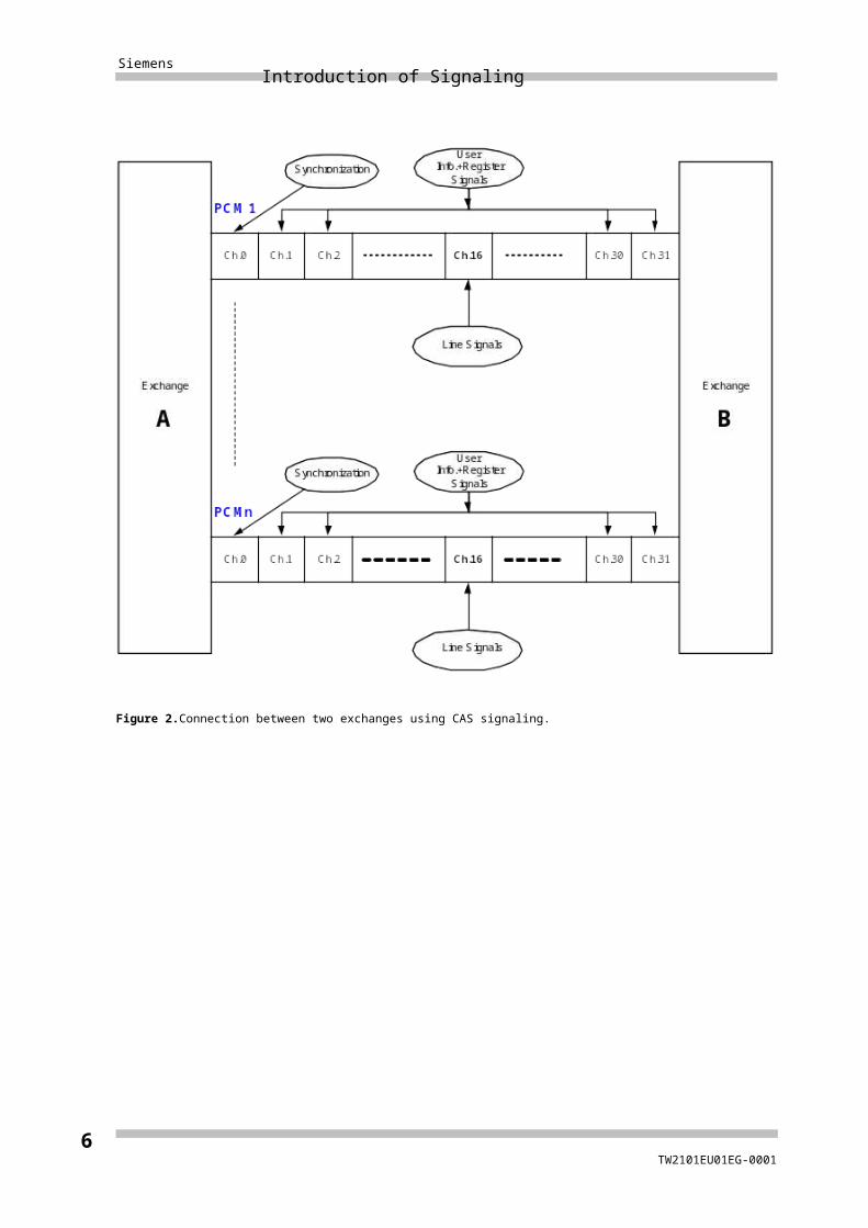
Type 1: Channel-associated signaling (CAS)
In such a system the 32 channels are divided as follows:
30 channels available for up to 30 voice calls and also can carry Register signals.
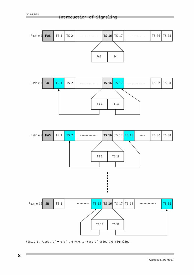
Channel (0) dedicated to carrying frame synchronization information. Channel (16)dedicated to carrying signaling information (Line signals).
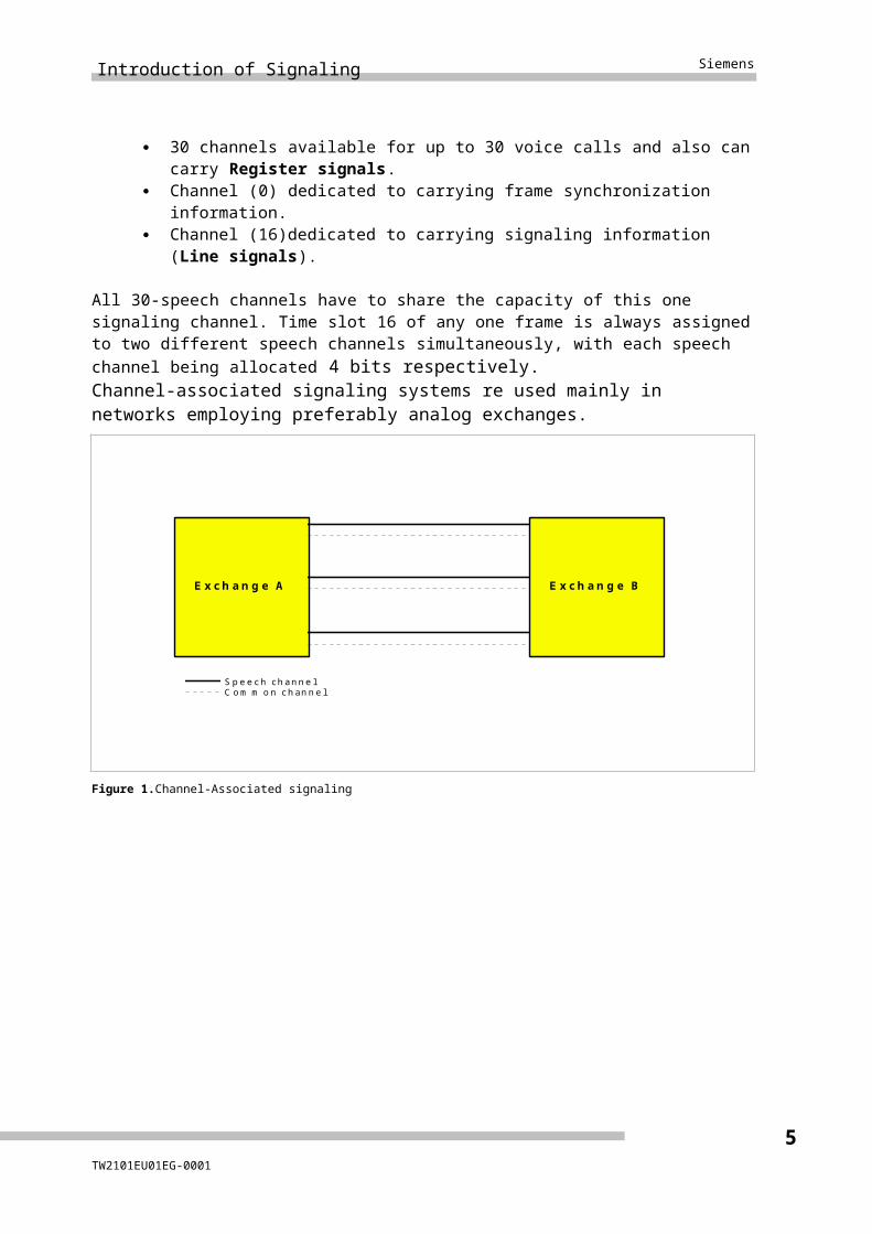
All 30-speech channels have to share the capacity of this one signaling channel. Time slot 16 of any one frame is always assigned to two different speech channels simultaneously, with each speech channel being allocated 4 bits respectively.Channel-associated signaling systems re used mainly in networks employing preferably analog exchanges.
TW2101EU01EG-00014
Introduction of Signaling Siemens
E x c h an g e A E x c h an g e B
S p e e c h c h an n e lC o m m o n c h an n e l
Figure 1.Channel-Associated signaling
Figure 2.Connection between two exchanges using CAS signaling.
TW2101EU01EG-00015
Siemens Introduction of Signaling
TW2101EU01EG-00016
Introduction of Signaling Siemens
Figure 3. Frames of one of the PCMs in case of using CAS signaling.
TW2101EU01EG-00017
Siemens Introduction of Signaling
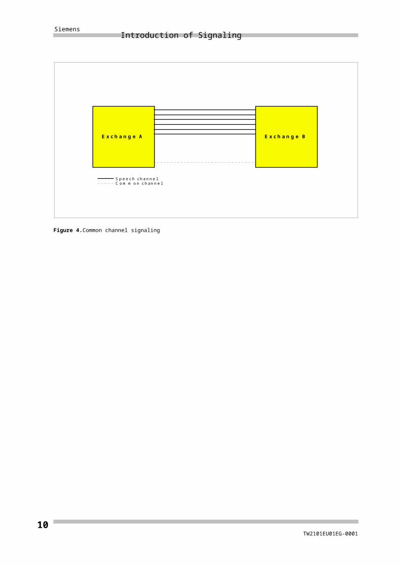
Type 2: Common channel signaling (CCS)
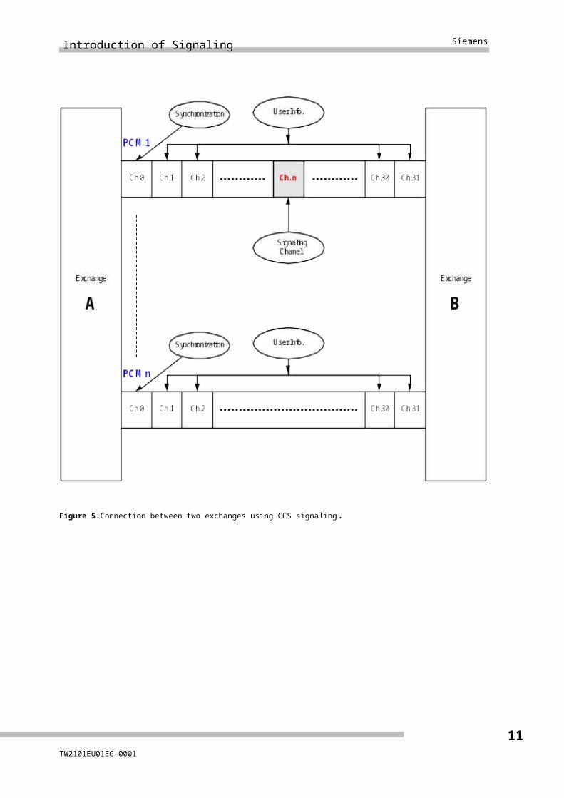
In such a system one common signaling channel is provided for a number of speech channels. Thus, the capacity of the signaling channel is available as a common pool and is used by the speech channels according to the dynamic demand, i.e. there is no permanent assignment of signaling channel to speech channel.
The common signaling channel (often referred to as signaling link) carries out the signaling information transport for a number of speech channels.
The signaling link can be viewed as a tunnel, which connects two exchanges, possesses a typical transmission rate of 64 kbit/s and accepts and conveys all signaling information.
Signaling information transfer is made possible by sending messages. A message is an information block whose structure and meaning of the single elements in the block are defined by specifications. The control of signaling information transfer is separated from the control of speech-channel through-connection.
E x c h a n g e A E x c h a n g e B
S p e e c h c h an n e lC o m m o n c h an n e l
Figure 4.Common channel signaling
TW2101EU01EG-00018
Introduction of Signaling Siemens
Figure 5.Connection between two exchanges using CCS signaling.
TW2101EU01EG-00019
Siemens Introduction of Signaling
What are the advantages of common channel signaling systems?
The separation between speech channel network and signaling network is the key to the more flexible communications networks of the future (ISDN).
The creation of common signaling channels allows unrestricted communication and flexible data transfer between two exchanges and/or their processors. This data transfer can also be used for network management, operating and administration functions.
The common signaling channels can also be used to exchange non-circuit-related control information between exchanges (e.g. CCBS, CCNR, IN applications, etc.).
Signaling information can be exchanged without regard to the speech channel or circuit status, and without disturbing the calling or called party.
Reduced call setup times thanks to the high transmission capacity (normally 64 kbit/s) and the usage of message structures (one message can include all called party digits).
Processor-friendly message structure (multiples of 8 bits).
Common channel signaling also supports services such as
User-to-user signaling Messages are exchanged directly between two terminals and pass through
the network in transparent mode.
End-to-end signaling Messages are exchanged between the originating and destination
exchange without being evaluated in the transit exchanges.
Reliability is high because error detection and correction measures provide for error-free message transmission. If one signaling link fails, Rerouting guarantees that the signaling information will still be transferred.
Like most modern protocols, the SS7 protocol is layered. The layered structure of the system gives us the ability to change a level without affecting the other levels. This means future services and applications can be implemented fast and cost-effectively
The first two common channel signaling systems specified internationally by ITU-T were
ITU-T signaling system No. 6 (CCS6) and
ITU-T signaling system No. 7 (SS7)
Only SS7 will be dealt with in this description.
TW2101EU01EG-000110
Introduction of Signaling Siemens
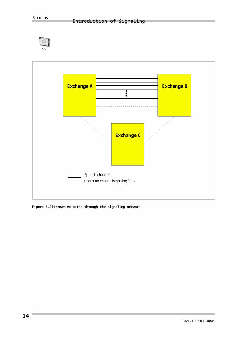
Exchange A Exchange B
Speech channels
Common channel signaling links
Exchange C
Figure 6.Alternative paths through the signaling network
TW2101EU01EG-000111
Siemens Introduction of Signaling
TW2101EU01EG-000112
Introduction of Signaling Siemens
Signaling Network
TW2101EU01EG-000113
Siemens Introduction of Signaling
2.1 Components of a SS7 Signaling
Network
Basic concepts
A telecommunications network served by common channel signalling is composed of a number of switching and processing nodes interconnected by transmission links. To communicate using SS7, each of these nodes requires to implement the necessary “within node” features of SS7 making that node a signalling point within the SS7 network. In addition, there will be a need to interconnect these signalling points such that SS7 signalling information (data) may be conveyed between them. These data links are the signalling links of SS7 signalling network.The combination of signalling points and their interconnecting signalling links form theSS No. 7 signalling network.
Signaling network components
Signaling points
A distinction is made between:
Signaling points (SP) and
Signaling transfer points (STP).
The signaling points are the sources (origination points) and sinks (destination points) of the signaling traffic. In a communications network both these points are usually exchanges.
The signaling transfer points forward received signaling messages to another signaling points. No call processing of the message takes place in a signaling
TW2101EU01EG-000114
Introduction of Signaling Siemens
transfer point. A signaling transfer point may be integrated in a signaling point (e.g. an exchange) or may be a separate node in the signaling network.
All signaling points in a SS No. 7 network are identified by a unique code known as a point code (Signaling Point Code (SPC)) defined by a corresponding numbering scheme and can therefore be addressed specifically in a signaling message.
Signaling link
The common channel signalling system uses signalling links (time slots belonging to an existing transmission route [e.g. a PCM30 link] ) to convey the signalling messages between two signalling points.
For redundancy purposes, more than one signaling link generally exists between two signaling points. If one signaling link fails the SS7 functions cause the signaling traffic to be diverted to functioning alternative links.
A number of signalling links that directly interconnect two signalling points forms what is called a signalling link-set.
Two signaling points that are directly interconnected by a signaling link are, from a signaling network structure point of view, referred to as adjacent signaling points.
TW2101EU01EG-000115
Siemens Introduction of Signaling
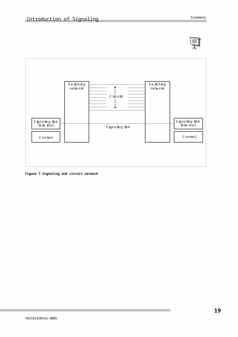
S w itch in gn etwo rk
C o ntro l
S ign a lin g linkte rm ina l
S ign a lin g linkte rm ina l
S w itch in gn etwo rk
C o ntro l
S ign a lin g link
C irc u its
Figure 7.Signaling and circuit network
TW2101EU01EG-000116
Introduction of Signaling Siemens
2.2 Modes of signaling
Two different signaling modes can be used in the signaling network.If the associated mode of signaling is used, the signaling link is routed together with the associated circuit group. That is to say, the signaling link is connected with those signaling points, which are also the end points of the circuit group. This signaling mode is recommended in cases where the traffic relation between the signaling points A and B carries high traffic loads. In the quasi-associated mode of signaling the signaling links and the circuit group follow different routes. Although the circuit group connects the signaling points A and B directly, one or more signaling transfer points handle the signaling for the circuit group. This mode is advantageous for less busy traffic relations as it allows one signaling link to be used for several destinations simultaneously.
TW2101EU01EG-000117
Siemens Introduction of Signaling
S i g n a l i n g p o i n t A S i g n a l i n g p o i n t B
C i r c u i t g r o u p
S i g n a l i n g l i n k
Figure 8.Associated mode of signaling
TW2101EU01EG-000118
Introduction of Signaling Siemens
S i g n a l i n g p o i n t A S i g n a l i n g p o i n t B
C i r c u i t g r o u p
S i g n a l i n g l i n k s
S i g n a l i n g p o i n t C /
s i g n a l i n g t r a n s f e r p o i n t
Figure 9.Quasi-associated mode of signaling
Signaling point modes
A signaling point, at which a message is generated, is the originating point of that
message.
A signaling point to which a message is destined, is the destination point of that
message.
A signalling point at which a message is received on one signalling link and is transferredto another link, is a Signal Transfer Point (STP).
Signaling routes
The path determined for the signaling between an origination point and a destination point is termed the signaling route. Between these two signaling points the signaling traffic can be distributed over several different signaling routes. All the signalling
TW2101EU01EG-000119
Siemens Introduction of Signaling
routes that may be used between an originating point and a destination point by a message traversing the signalling network is the signalling route set for that signalling relation.
In Figure 10 the signaling routes from A to B are LSET1, LSET2 and LSET3. These routes comprise the signaling route set for B.
TW2101EU01EG-000120

Introduction of Signaling Siemens
Originatingpoint A
Destinationpoint BLSET2
T2 T4
T1 T5
T3
LSET3
LSET1
Tx: Signaling transfer point
Figure 10.Signaling route set
TW2101EU01EG-000121

Siemens Introduction of Signaling
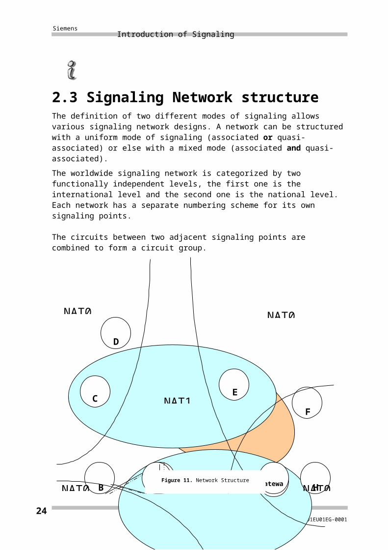
2.3 Signaling Network structure
The definition of two different modes of signaling allows various signaling network designs. A network can be structured with a uniform mode of signaling (associated or quasi-associated) or else with a mixed mode (associated and quasi-associated).
The worldwide signaling network is categorized by two functionally independent levels, the first one is the international level and the second one is the national level. Each network has a separate numbering scheme for its own signaling points.
The circuits between two adjacent signaling points are combined to form a circuit group.
TW2101EU01EG-000122
B A G
F
D
C E
NAT1
NAT1
NAT0
NAT0
NAT0
H NAT0 Gateway
INAT0 Gateway
Figure 11. Network Structure

Introduction of Signaling Siemens
TW2101EU01EG-000123
Siemens Introduction of Signaling
TW2101EU01EG-000124