Embed Size (px)
Citation preview
Thermal Fatigue Management Guideline for Normally Stagnant Non-Isolable RCS Branch Lines
Shannon Chu EPRI Bob McGill Structural Integrity Associates January 5, 2012
2 © 2012 Electric Power Research Institute, Inc. All rights reserved.
Introduction
• The EPRI MRP has an ongoing program (MRP-146) to assist PWR owners manage thermal fatigue concerns in normally stagnant, non-isolable reactor coolant system branch lines • MRP-146 contains “Needed” requirements as part of the
NEI 03-08 materials initiative • The EPRI MRP has met with NRC previously to present
these industry efforts: – May 2005 (MRP-146 program discussed) – April 2009 (MRP-146S supplement discussed)
3 © 2012 Electric Power Research Institute, Inc. All rights reserved.
Introduction (2)
• Since the 2009 meeting: – PWR fleet surveyed and plant screening information
obtained – Initial inspections for all screened in branch lines have
been completed – MRP-146R1 was published (June 2011)
4 © 2012 Electric Power Research Institute, Inc. All rights reserved.
Introduction (3)
• Purpose of this meeting: – Inform NRC of important developments since last
meeting on this subject – Provide overview of MRP-146R1 and implementation
plan – Summarize ongoing activities
• Entertain comments and discussion – NRC approval is not being requested
5 © 2012 Electric Power Research Institute, Inc. All rights reserved.
Presentation Content
• MRP-146 program background • MRP-146S implementation experience • Overview of MRP-146R1 changes • MRP-146R1 “Needed” requirements in revised branch line
assessment methods • Summary of improved MRP-146R1 guidance for:
– Monitoring – Inspection – Mitigation
• MRP-146R1 implementation and next steps • Conclusions
6 © 2012 Electric Power Research Institute, Inc. All rights reserved.
MRP-146 Program Background
7 © 2012 Electric Power Research Institute, Inc. All rights reserved.
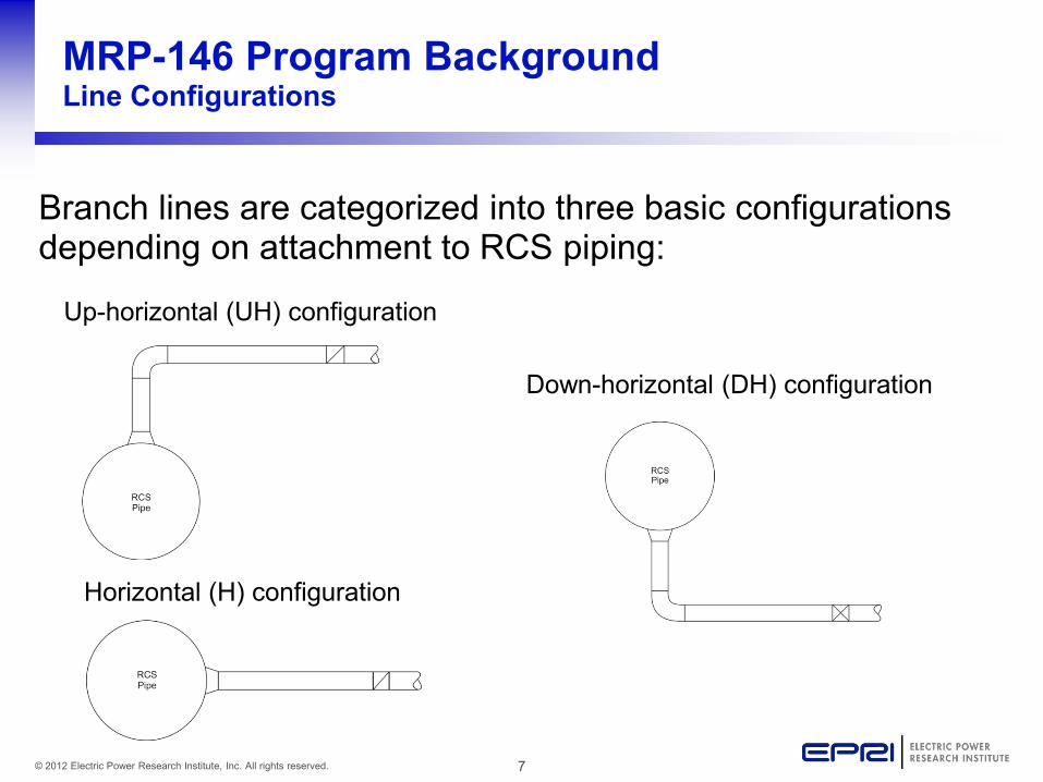
MRP-146 Program Background Line Configurations
Branch lines are categorized into three basic configurations depending on attachment to RCS piping:
Up-horizontal (UH) configuration
Down-horizontal (DH) configuration
Horizontal (H) configuration
8 © 2012 Electric Power Research Institute, Inc. All rights reserved.
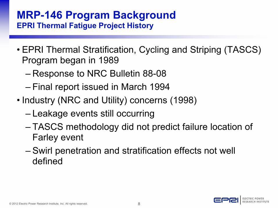
MRP-146 Program Background EPRI Thermal Fatigue Project History
• EPRI Thermal Stratification, Cycling and Striping (TASCS) Program began in 1989 – Response to NRC Bulletin 88-08 – Final report issued in March 1994
• Industry (NRC and Utility) concerns (1998) – Leakage events still occurring – TASCS methodology did not predict failure location of
Farley event – Swirl penetration and stratification effects not well
defined
9 © 2012 Electric Power Research Institute, Inc. All rights reserved.
MRP-146 Program Background EPRI Thermal Fatigue Project History (2)
• EPRI/MRP formed the Thermal Fatigue Issue Task Group (ITG) in 1999 - established to proactively address concerns with pipe leaks in non-isolable piping attached to the RCS • Interim guidance issued in 2001 (MRP-24)
– Focus on lines which had exhibited leakage in service – Provided screening criteria based on experience and
limited experimental work, inspection recommendations – Inspection interval & other potentially susceptible lines
not addressed
10 © 2012 Electric Power Research Institute, Inc. All rights reserved.
MRP-146 Program Background EPRI Thermal Fatigue Project History (3)
• Additional research continued on model development – Small scale phenomena testing – Review of available plant data and OE
• Model completed in 2004 (MRP-132) • Management guideline published in 2005 (MRP-146) • MRP fatigue efforts moved under the Technical Support
Committee (TSC) in 2006 • Plant assessments completed in 2007 using EPRI QA
software implementing the MRP-132 model (MRP-170) • MRP-146 supplemental guidance published in January
2009 (MRP-146S) • MRP-146R1 published in June 2011
11 © 2012 Electric Power Research Institute, Inc. All rights reserved.
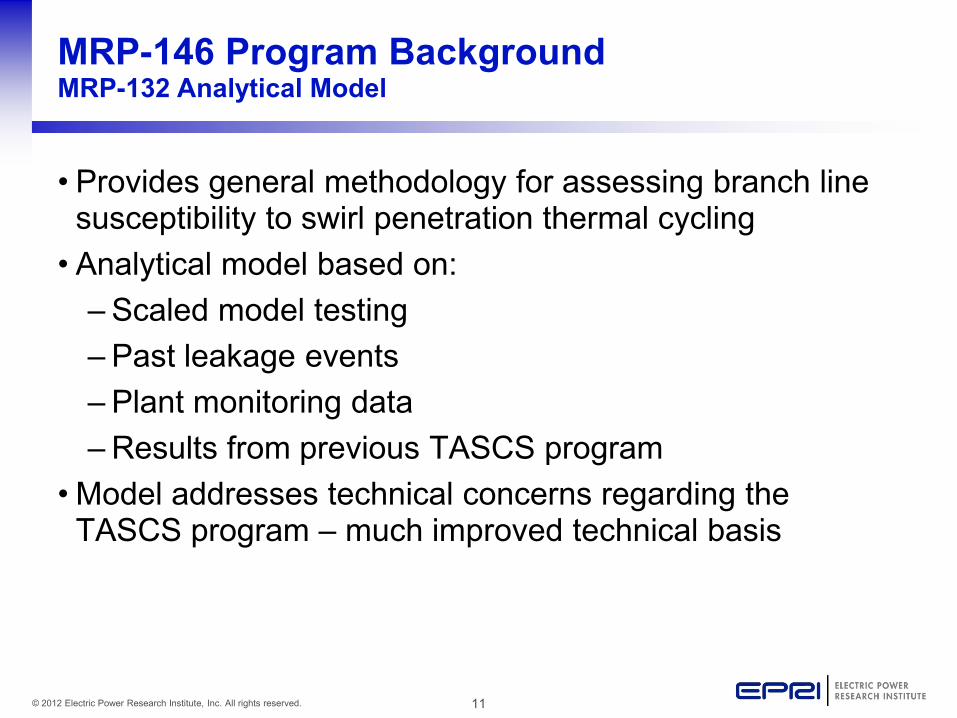
MRP-146 Program Background MRP-132 Analytical Model
• Provides general methodology for assessing branch line susceptibility to swirl penetration thermal cycling • Analytical model based on:
– Scaled model testing – Past leakage events – Plant monitoring data – Results from previous TASCS program
• Model addresses technical concerns regarding the TASCS program – much improved technical basis
12 © 2012 Electric Power Research Institute, Inc. All rights reserved.
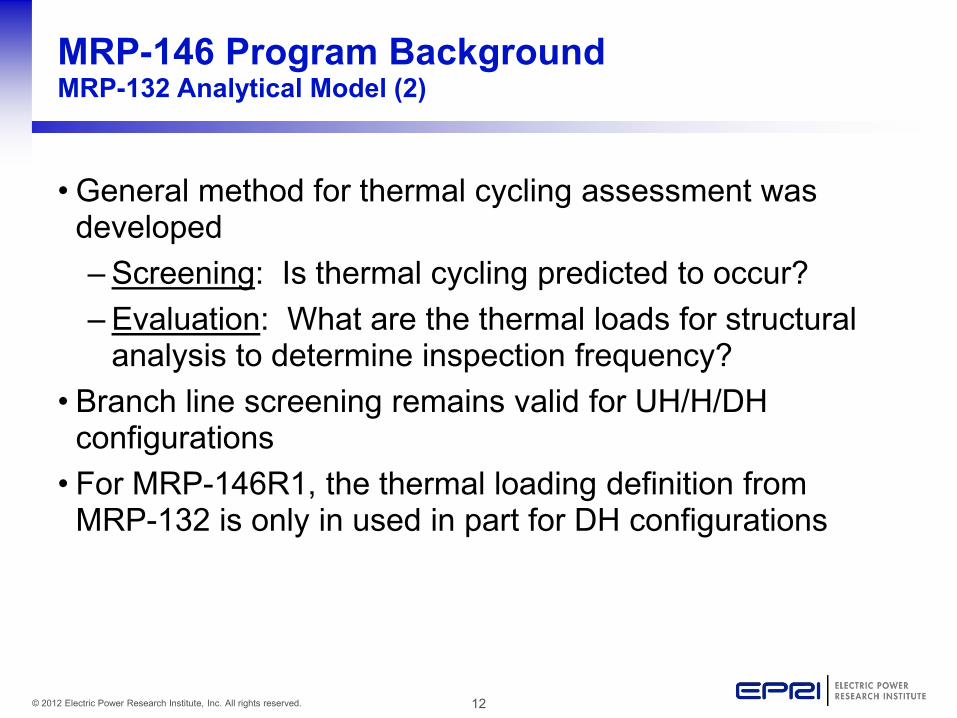
MRP-146 Program Background MRP-132 Analytical Model (2)
• General method for thermal cycling assessment was developed – Screening: Is thermal cycling predicted to occur? – Evaluation: What are the thermal loads for structural
analysis to determine inspection frequency? • Branch line screening remains valid for UH/H/DH
configurations • For MRP-146R1, the thermal loading definition from
MRP-132 is only in used in part for DH configurations
13 © 2012 Electric Power Research Institute, Inc. All rights reserved.
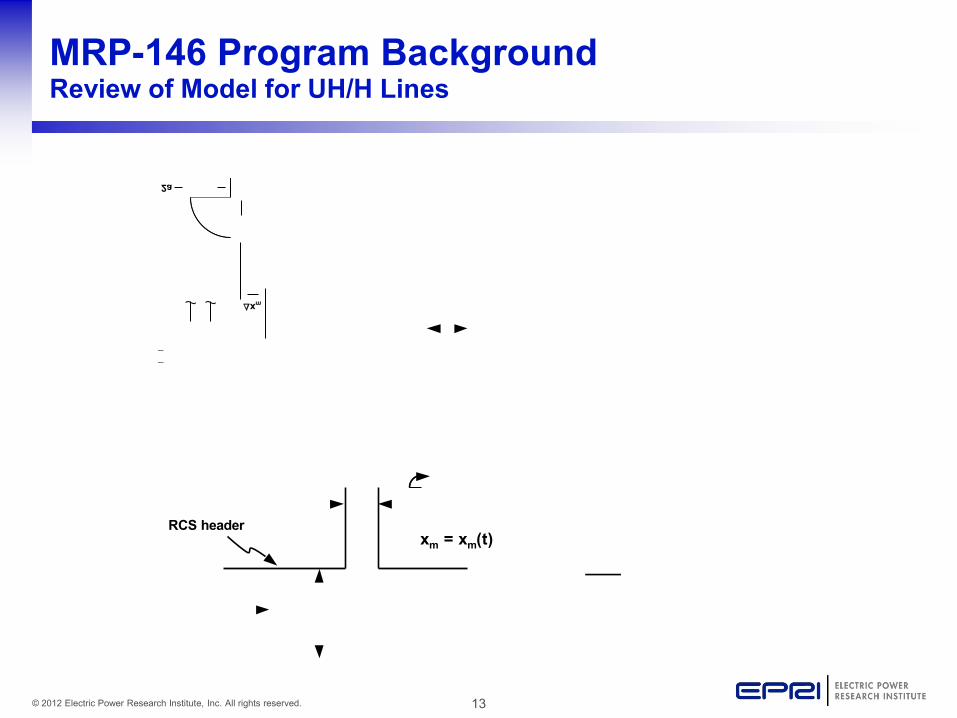
MRP-146 Program Background Review of Model for UH/H Lines
xm = xm(t)RCS header
2a
∆xm
14 © 2012 Electric Power Research Institute, Inc. All rights reserved.
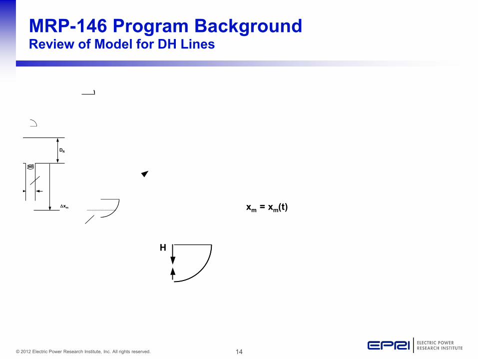
MRP-146 Program Background Review of Model for DH Lines
H
xm = xm(t)
∆xm
DR
15 © 2012 Electric Power Research Institute, Inc. All rights reserved.
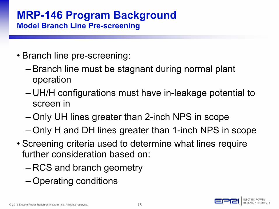
MRP-146 Program Background Model Branch Line Pre-screening
• Branch line pre-screening: – Branch line must be stagnant during normal plant
operation – UH/H configurations must have in-leakage potential to
screen in – Only UH lines greater than 2-inch NPS in scope – Only H and DH lines greater than 1-inch NPS in scope
• Screening criteria used to determine what lines require further consideration based on: – RCS and branch geometry – Operating conditions
16 © 2012 Electric Power Research Institute, Inc. All rights reserved.
MRP-146S Implementation Experience
17 © 2012 Electric Power Research Institute, Inc. All rights reserved.
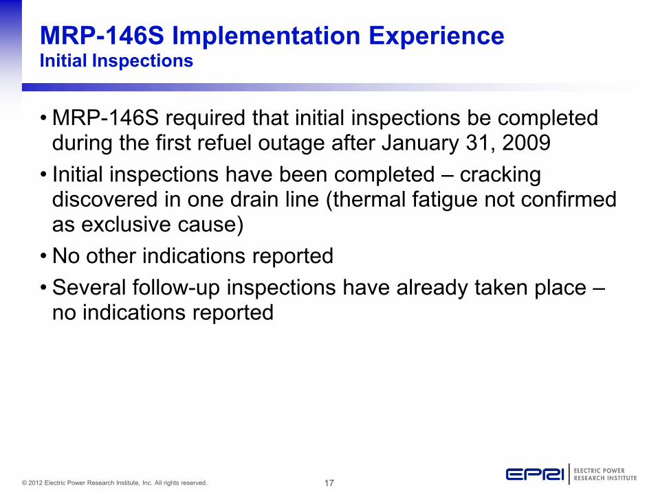
MRP-146S Implementation Experience Initial Inspections
• MRP-146S required that initial inspections be completed during the first refuel outage after January 31, 2009 • Initial inspections have been completed – cracking
discovered in one drain line (thermal fatigue not confirmed as exclusive cause) • No other indications reported • Several follow-up inspections have already taken place –
no indications reported
18 © 2012 Electric Power Research Institute, Inc. All rights reserved.
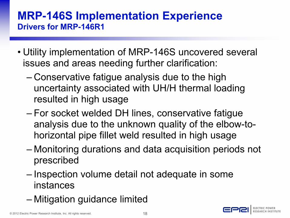
MRP-146S Implementation Experience Drivers for MRP-146R1
• Utility implementation of MRP-146S uncovered several issues and areas needing further clarification: – Conservative fatigue analysis due to the high
uncertainty associated with UH/H thermal loading resulted in high usage
– For socket welded DH lines, conservative fatigue analysis due to the unknown quality of the elbow-to-horizontal pipe fillet weld resulted in high usage
– Monitoring durations and data acquisition periods not prescribed
– Inspection volume detail not adequate in some instances
– Mitigation guidance limited
19 © 2012 Electric Power Research Institute, Inc. All rights reserved.
Overview of MRP-146R1 Changes
20 © 2012 Electric Power Research Institute, Inc. All rights reserved.
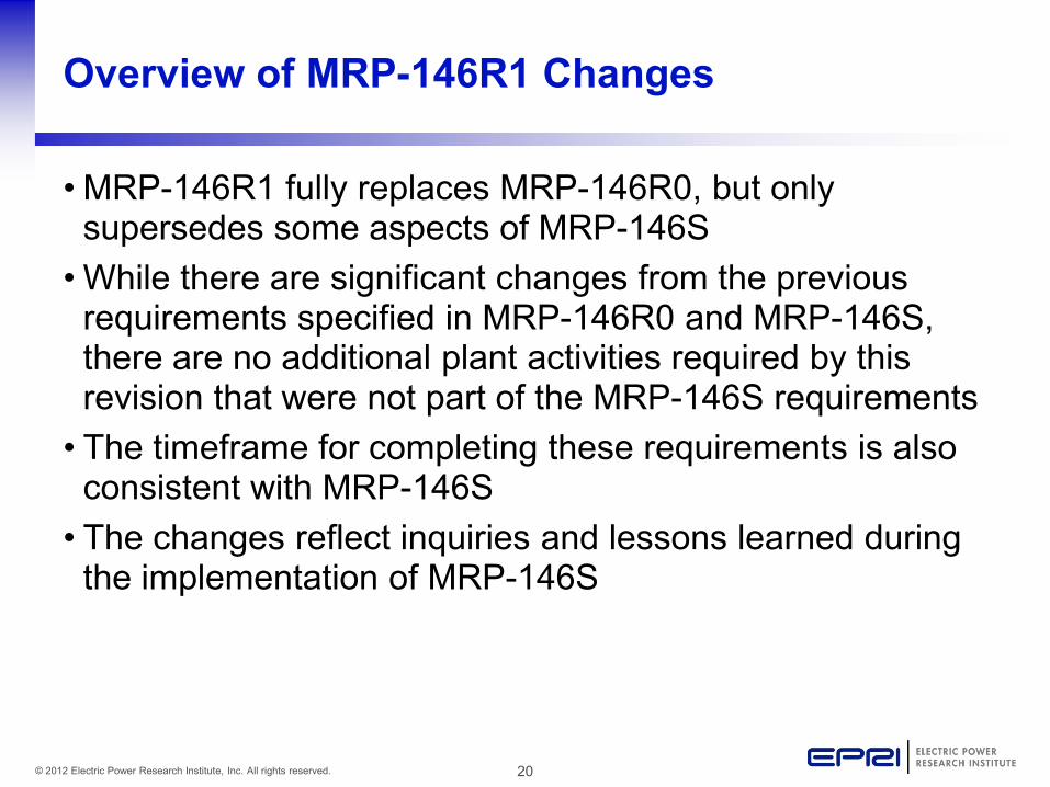
Overview of MRP-146R1 Changes
• MRP-146R1 fully replaces MRP-146R0, but only supersedes some aspects of MRP-146S • While there are significant changes from the previous
requirements specified in MRP-146R0 and MRP-146S, there are no additional plant activities required by this revision that were not part of the MRP-146S requirements • The timeframe for completing these requirements is also
consistent with MRP-146S • The changes reflect inquiries and lessons learned during
the implementation of MRP-146S
21 © 2012 Electric Power Research Institute, Inc. All rights reserved.
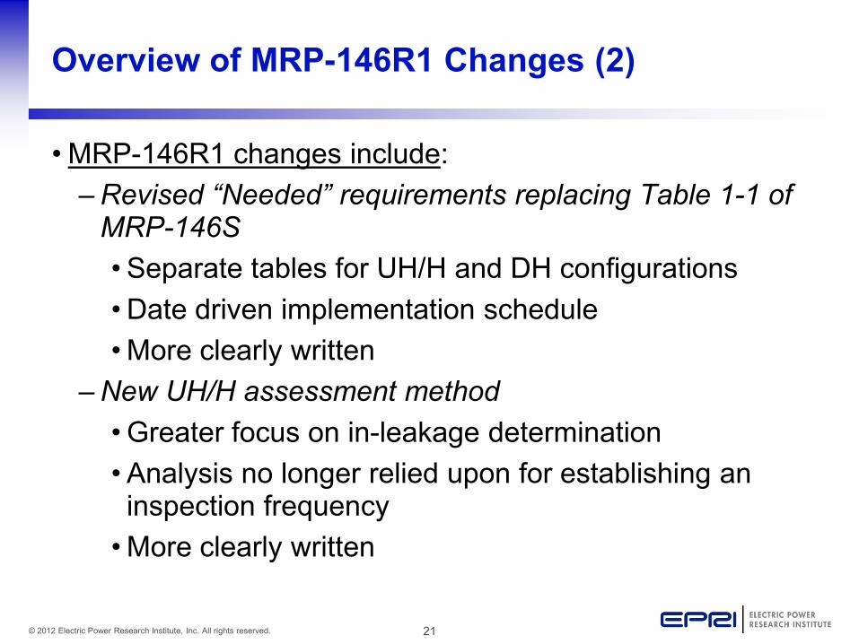
Overview of MRP-146R1 Changes (2)
• MRP-146R1 changes include: – Revised “Needed” requirements replacing Table 1-1 of
MRP-146S •Separate tables for UH/H and DH configurations •Date driven implementation schedule •More clearly written
– New UH/H assessment method •Greater focus on in-leakage determination •Analysis no longer relied upon for establishing an inspection frequency •More clearly written
22 © 2012 Electric Power Research Institute, Inc. All rights reserved.
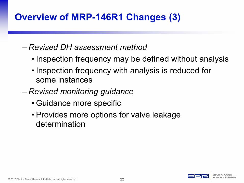
Overview of MRP-146R1 Changes (3)
– Revised DH assessment method • Inspection frequency may be defined without analysis • Inspection frequency with analysis is reduced for some instances
– Revised monitoring guidance •Guidance more specific •Provides more options for valve leakage determination
23 © 2012 Electric Power Research Institute, Inc. All rights reserved.
Overview of MRP-146R1 Changes (4)
– Revised inspection guidance • Inspection volumes slightly modified •Examination volume details provided for socket welded branches and UH/H horizontal sections
– Expanded thermal fatigue mitigation guidance •Several plant modifications discussed w/ examples •Valve maintenance actions provided to help prevent leakage
24 © 2012 Electric Power Research Institute, Inc. All rights reserved.
MRP-146R1 “Needed” Requirements in Revised UH/H and DH Assessment
Methods
25 © 2012 Electric Power Research Institute, Inc. All rights reserved.
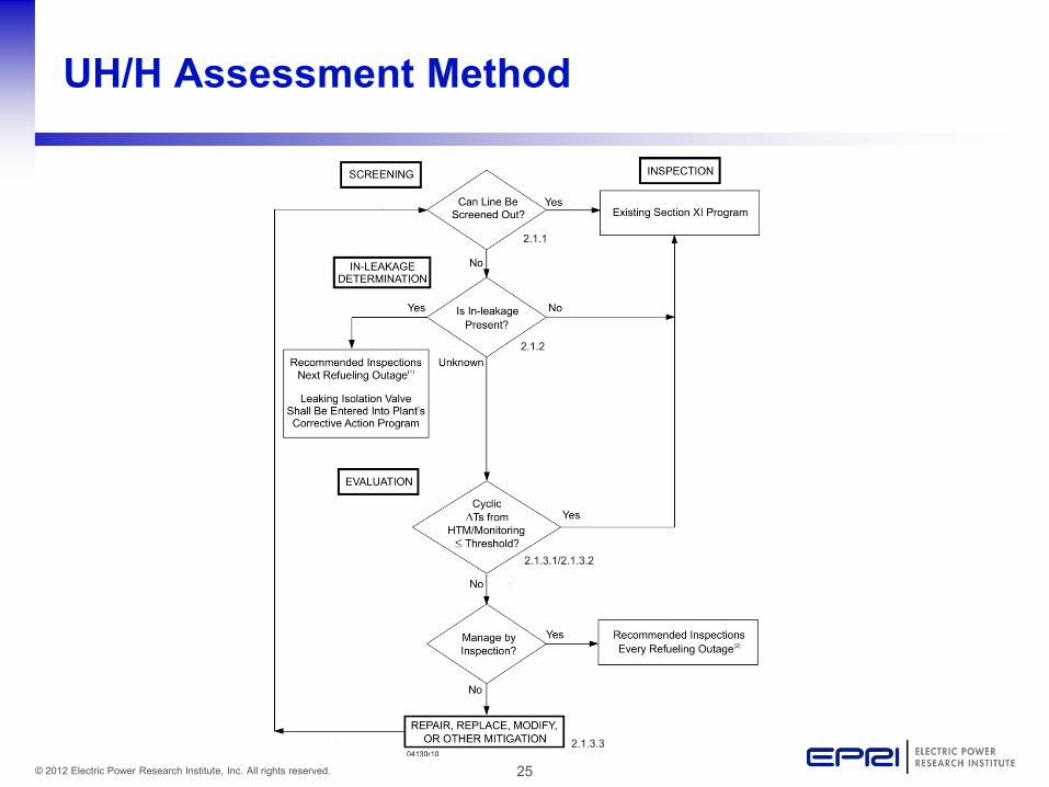
UH/H Assessment Method
26 © 2012 Electric Power Research Institute, Inc. All rights reserved.
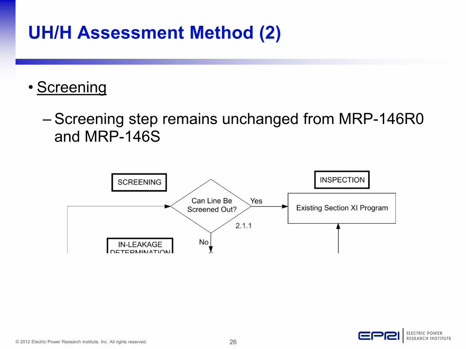
UH/H Assessment Method (2)
• Screening
– Screening step remains unchanged from MRP-146R0 and MRP-146S
27 © 2012 Electric Power Research Institute, Inc. All rights reserved.
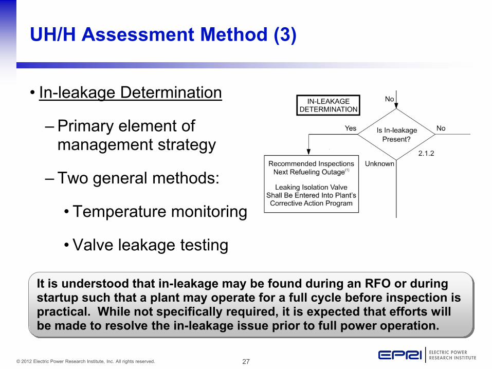
UH/H Assessment Method (3)
• In-leakage Determination
– Primary element of management strategy
– Two general methods:
• Temperature monitoring
•Valve leakage testing
It is understood that in-leakage may be found during an RFO or during startup such that a plant may operate for a full cycle before inspection is practical. While not specifically required, it is expected that efforts will be made to resolve the in-leakage issue prior to full power operation.
28 © 2012 Electric Power Research Institute, Inc. All rights reserved.
UH/H Assessment Method (4)
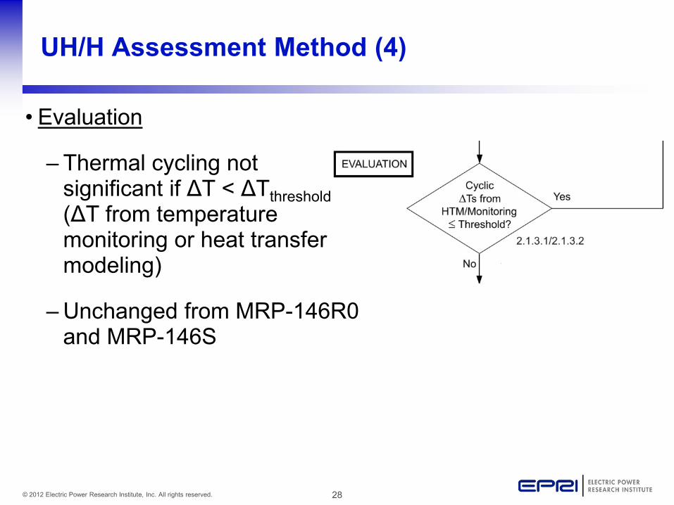
• Evaluation
– Thermal cycling not significant if ΔT < ΔTthreshold (ΔT from temperature monitoring or heat transfer modeling)
– Unchanged from MRP-146R0 and MRP-146S
29 © 2012 Electric Power Research Institute, Inc. All rights reserved.
UH/H Assessment Method (5)
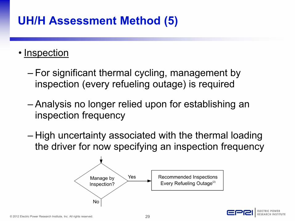
• Inspection
– For significant thermal cycling, management by inspection (every refueling outage) is required
– Analysis no longer relied upon for establishing an inspection frequency
– High uncertainty associated with the thermal loading the driver for now specifying an inspection frequency
30 © 2012 Electric Power Research Institute, Inc. All rights reserved.
UH/H Assessment Method (6)
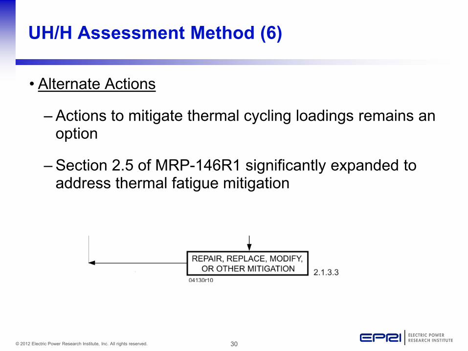
• Alternate Actions
– Actions to mitigate thermal cycling loadings remains an option
– Section 2.5 of MRP-146R1 significantly expanded to address thermal fatigue mitigation
31 © 2012 Electric Power Research Institute, Inc. All rights reserved.
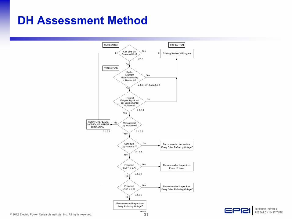
DH Assessment Method
32 © 2012 Electric Power Research Institute, Inc. All rights reserved.
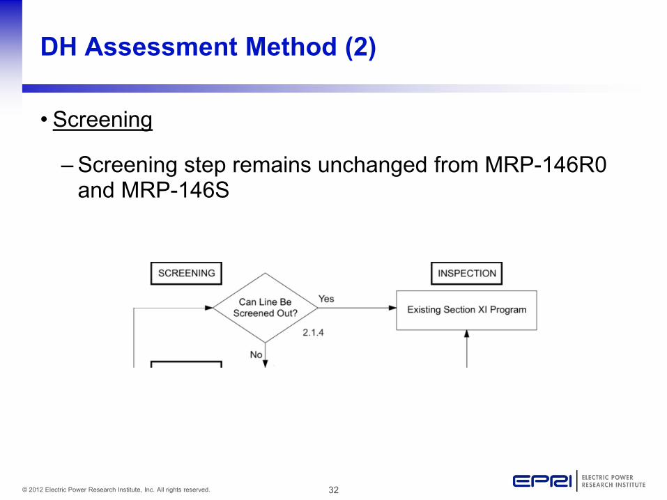
DH Assessment Method (2)
• Screening
– Screening step remains unchanged from MRP-146R0 and MRP-146S
33 © 2012 Electric Power Research Institute, Inc. All rights reserved.
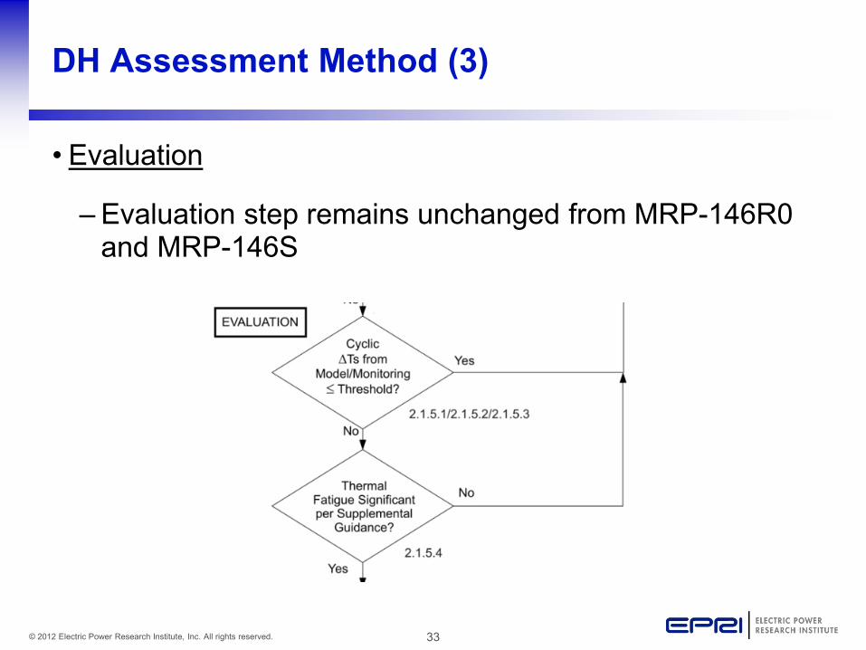
DH Assessment Method (3)
• Evaluation
– Evaluation step remains unchanged from MRP-146R0 and MRP-146S
34 © 2012 Electric Power Research Institute, Inc. All rights reserved.
DH Assessment Method (4)
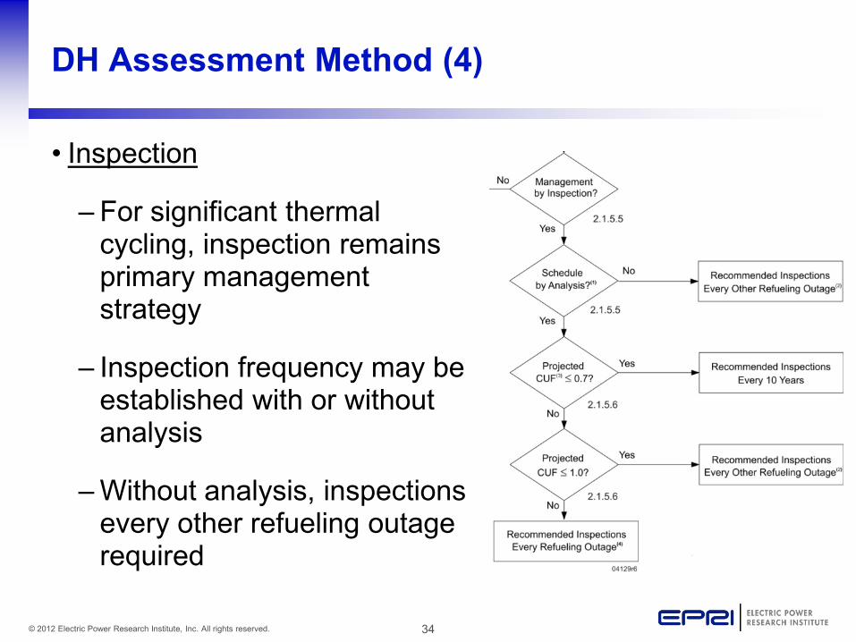
• Inspection
– For significant thermal cycling, inspection remains primary management strategy
– Inspection frequency may be established with or without analysis
– Without analysis, inspections every other refueling outage required
35 © 2012 Electric Power Research Institute, Inc. All rights reserved.
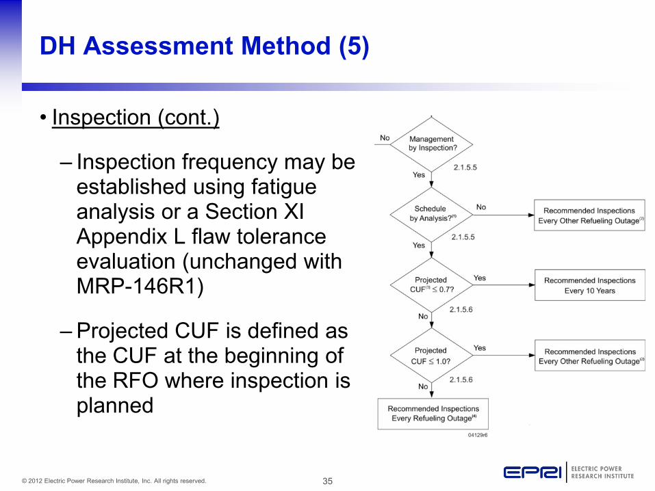
DH Assessment Method (5)
• Inspection (cont.)
– Inspection frequency may be established using fatigue analysis or a Section XI Appendix L flaw tolerance evaluation (unchanged with MRP-146R1)
– Projected CUF is defined as the CUF at the beginning of the RFO where inspection is planned
36 © 2012 Electric Power Research Institute, Inc. All rights reserved.
DH Assessment Method (6)
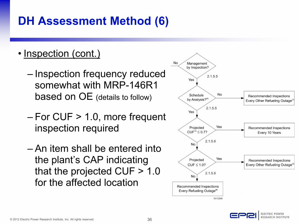
• Inspection (cont.)
– Inspection frequency reduced somewhat with MRP-146R1 based on OE (details to follow)
– For CUF > 1.0, more frequent inspection required
– An item shall be entered into the plant’s CAP indicating that the projected CUF > 1.0 for the affected location
37 © 2012 Electric Power Research Institute, Inc. All rights reserved.
DH Assessment Method (7)
• Inspection (cont.)
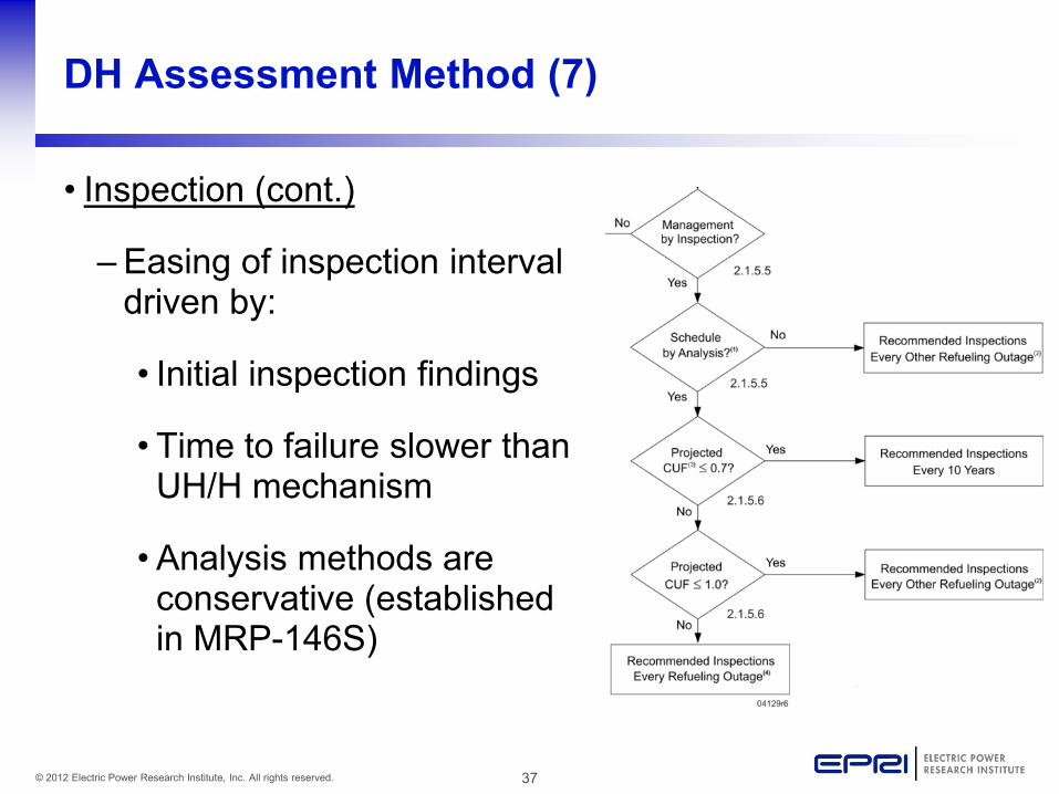
– Easing of inspection interval driven by:
• Initial inspection findings
• Time to failure slower than UH/H mechanism
•Analysis methods are conservative (established in MRP-146S)
38 © 2012 Electric Power Research Institute, Inc. All rights reserved.
DH Assessment Method (8)
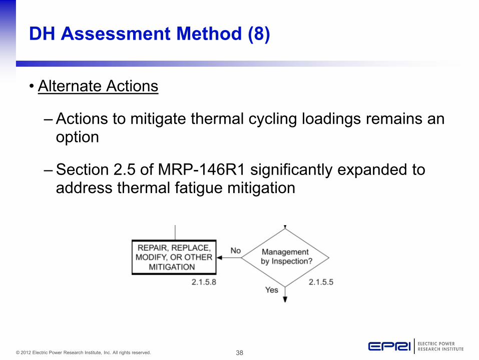
• Alternate Actions
– Actions to mitigate thermal cycling loadings remains an option
– Section 2.5 of MRP-146R1 significantly expanded to address thermal fatigue mitigation
39 © 2012 Electric Power Research Institute, Inc. All rights reserved.
Summary of Improved MRP-146R1 Guidance
40 © 2012 Electric Power Research Institute, Inc. All rights reserved.
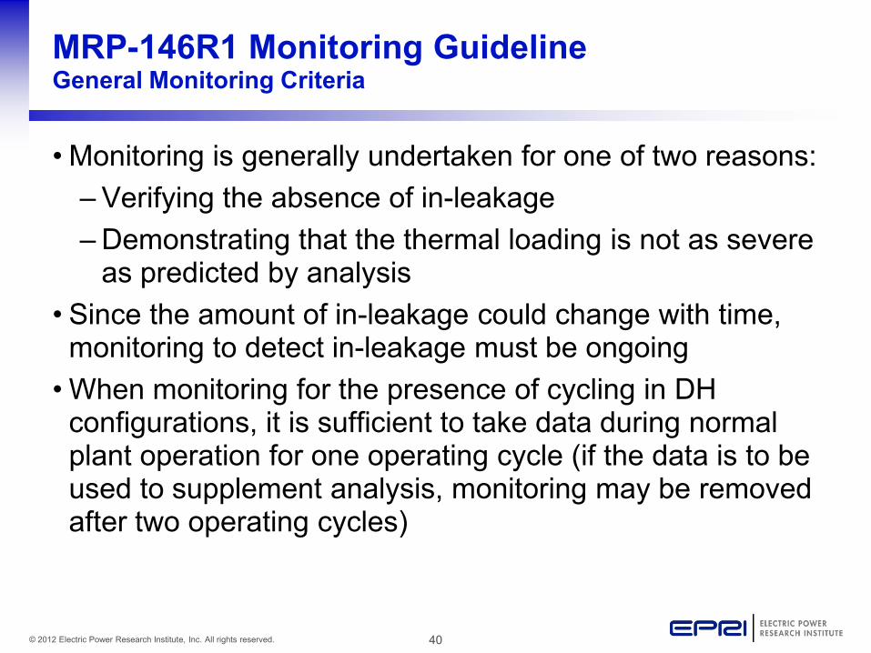
MRP-146R1 Monitoring Guideline General Monitoring Criteria
• Monitoring is generally undertaken for one of two reasons: – Verifying the absence of in-leakage – Demonstrating that the thermal loading is not as severe
as predicted by analysis • Since the amount of in-leakage could change with time,
monitoring to detect in-leakage must be ongoing • When monitoring for the presence of cycling in DH
configurations, it is sufficient to take data during normal plant operation for one operating cycle (if the data is to be used to supplement analysis, monitoring may be removed after two operating cycles)
41 © 2012 Electric Power Research Institute, Inc. All rights reserved.
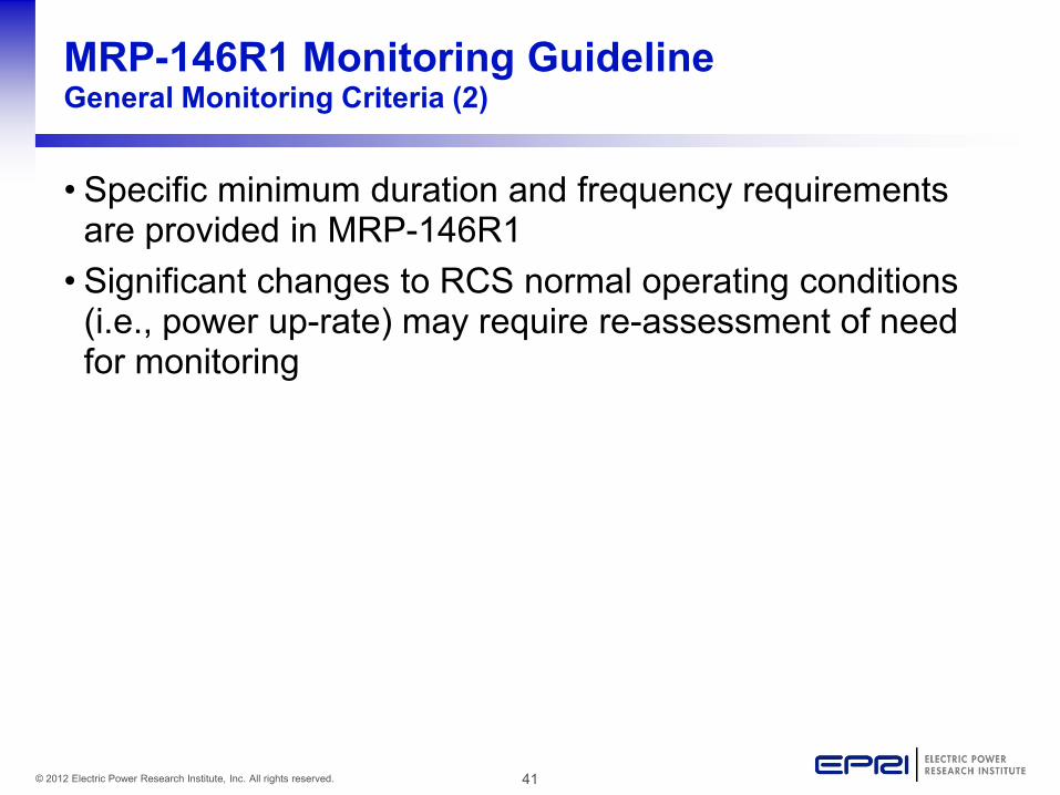
MRP-146R1 Monitoring Guideline General Monitoring Criteria (2)
• Specific minimum duration and frequency requirements are provided in MRP-146R1 • Significant changes to RCS normal operating conditions
(i.e., power up-rate) may require re-assessment of need for monitoring
42 © 2012 Electric Power Research Institute, Inc. All rights reserved.
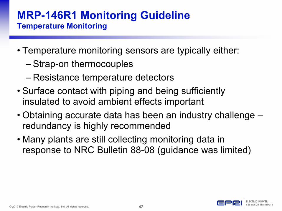
MRP-146R1 Monitoring Guideline Temperature Monitoring
• Temperature monitoring sensors are typically either: – Strap-on thermocouples – Resistance temperature detectors
• Surface contact with piping and being sufficiently insulated to avoid ambient effects important • Obtaining accurate data has been an industry challenge –
redundancy is highly recommended • Many plants are still collecting monitoring data in
response to NRC Bulletin 88-08 (guidance was limited)
43 © 2012 Electric Power Research Institute, Inc. All rights reserved.
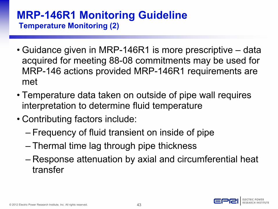
MRP-146R1 Monitoring Guideline Temperature Monitoring (2)
• Guidance given in MRP-146R1 is more prescriptive – data acquired for meeting 88-08 commitments may be used for MRP-146 actions provided MRP-146R1 requirements are met • Temperature data taken on outside of pipe wall requires
interpretation to determine fluid temperature • Contributing factors include:
– Frequency of fluid transient on inside of pipe – Thermal time lag through pipe thickness – Response attenuation by axial and circumferential heat
transfer
44 © 2012 Electric Power Research Institute, Inc. All rights reserved.
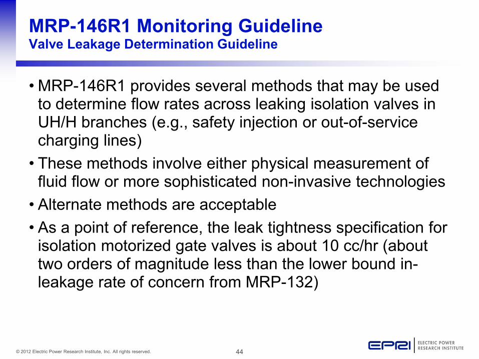
MRP-146R1 Monitoring Guideline Valve Leakage Determination Guideline
• MRP-146R1 provides several methods that may be used to determine flow rates across leaking isolation valves in UH/H branches (e.g., safety injection or out-of-service charging lines) • These methods involve either physical measurement of
fluid flow or more sophisticated non-invasive technologies • Alternate methods are acceptable • As a point of reference, the leak tightness specification for
isolation motorized gate valves is about 10 cc/hr (about two orders of magnitude less than the lower bound in-leakage rate of concern from MRP-132)
45 © 2012 Electric Power Research Institute, Inc. All rights reserved.
MRP-146R1 Inspection Guidelines General Examination Requirements
• General examination requirements remain for the most part unchanged • Requirement for examiners to be familiar with the unique
aspects of inspection for thermal fatigue damage and for geometric considerations specific to small diameter piping now allows for alternate training methods beyond only the EPRI computer based training, MRP-36R1 • The EPRI NDE Center has thermal fatigue mock-ups
available for utility training/practice
46 © 2012 Electric Power Research Institute, Inc. All rights reserved.
MRP-146R1 Inspection Guidelines Inspection Volumes
• Several inspection volume changes and clarifications are made in MRP-146R1: – Base metal inspection requirement more clearly
defined (for UH/H horizontal pipe sections) – Examination zone for socket-welded lines increased
and more clearly defined – Two new figures added for clarity
• Examination guidance for elbow base metal and full penetration welds remains unchanged (for branches w/ butt-welded construction)
47 © 2012 Electric Power Research Institute, Inc. All rights reserved.
MRP-146R1 Thermal Fatigue Mitigation Guideline
• Thermal fatigue mitigation may be used to eliminate or reduce the potential or severity of future thermal fatigue cycling • Significantly expanded guidance included in MRP-146R1 • Actions may include:
– Plant modifications – Changes in plant operation – Preventative isolation valve maintenance
• Examples are provided for many of the actions described
48 © 2012 Electric Power Research Institute, Inc. All rights reserved.
MRP-146R1 Implementation and Next Steps
49 © 2012 Electric Power Research Institute, Inc. All rights reserved.
MRP-146R1 Implementation
• EPRI sponsored utility training for MRP-146R1 is underway (three sessions completed in 2011) • Implementation of MRP-146R1 shall be complete by
utilities and reflected in plant documentation as of the first RFO that initiates after January 31, 2012
50 © 2012 Electric Power Research Institute, Inc. All rights reserved.
Next Steps
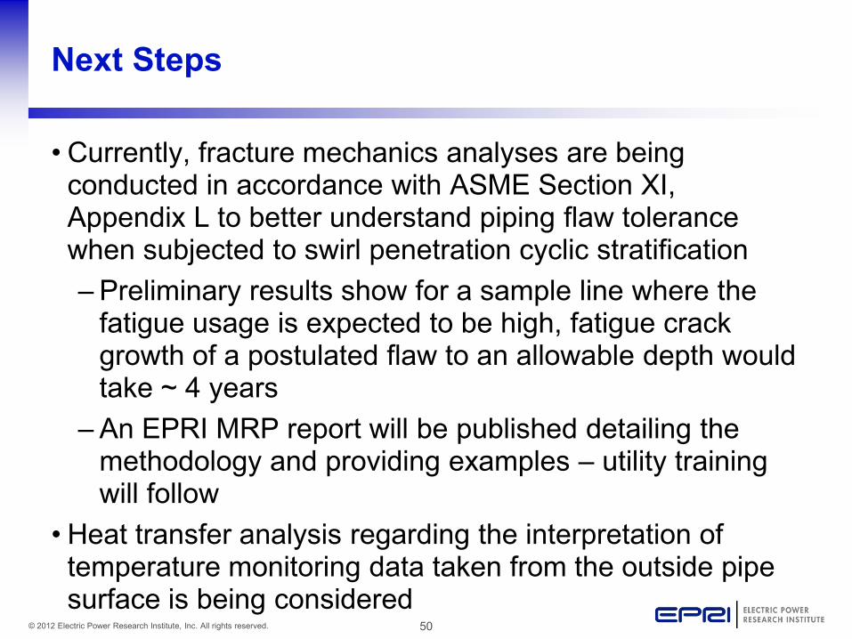
• Currently, fracture mechanics analyses are being conducted in accordance with ASME Section XI, Appendix L to better understand piping flaw tolerance when subjected to swirl penetration cyclic stratification – Preliminary results show for a sample line where the
fatigue usage is expected to be high, fatigue crack growth of a postulated flaw to an allowable depth would take ~ 4 years
– An EPRI MRP report will be published detailing the methodology and providing examples – utility training will follow
• Heat transfer analysis regarding the interpretation of temperature monitoring data taken from the outside pipe surface is being considered
51 © 2012 Electric Power Research Institute, Inc. All rights reserved.
Conclusions
52 © 2012 Electric Power Research Institute, Inc. All rights reserved.
Conclusions
• MRP-146R1 allows for progressively more specific and rigorous evaluation as part of the assessment process – General screening – Determine significance of thermal fatigue potential – Inspection frequency based on severity of loading
• Many conservatisms inherent with each level • MRP-146R1 provides utilities with the most current
implementation guidance (replacing Rev. 0)
53 © 2012 Electric Power Research Institute, Inc. All rights reserved.
Conclusions (2)
• MRP-146R1 and supporting documents provide an effective approach to managing thermal fatigue in normally stagnant, non-isolable RCS branch lines • PWR owners are using this approach moving forward • EPRI committed to keeping the guidance current through
future revision based on owner operating experience
54 © 2012 Electric Power Research Institute, Inc. All rights reserved.
Comments and Discussion