Embed Size (px)
Citation preview

M4 System with Mx Computer and Mac Pro
User guide


Contents | ii
Contents
Legal.................................................................................................4History...........................................................................................................................................................................4Copyright......................................................................................................................................................................5Disclaimer.................................................................................................................................................................... 5
Introduction and Presentation..........................................................6Introduction................................................................................................................................................................6Safety Guidelines...................................................................................................................................................... 7Description.................................................................................................................................................................. 8
M4 and Mx computer System Overview.............................................................................................8Equipment List..............................................................................................................................................9Technical Specifications........................................................................................................................... 11
Computer Configuration..................................................................12Adding a Virtual Keyboard..................................................................................................................................12
Installation......................................................................................14Installing the System............................................................................................................................................ 14System Cabling........................................................................................................................................................ 14Powering the Mx computer................................................................................................................................16Configuring Mac Pro Network...........................................................................................................................16Installing Hydrophones........................................................................................................................................18
List of Marport Hydrophones................................................................................................................18Connecting the Hydrophone to the Receiver..................................................................................20Adding Temperature Data from the Hydrophones to the System...........................................21
Understanding Receiver LEDs...........................................................................................................................22
Servicing and Maintenance.............................................................23Interference Check.................................................................................................................................................23
Spectrum Analyzer Display....................................................................................................23 Checking Noise Interference................................................................................................. 24 Checking Noise Interference................................................................................................. 25
Estimating the Efficiency of Hydrophones..................................................................................................29Troubleshooting.......................................................................................................................................................31
No Internet Access..................................................................................................................................... 31Antifouling System Causes Interferences......................................................................................... 31
Giving Remote Access to the Computer........................................................................................................32Recording Audio Files...........................................................................................................................................32Support Contact...................................................................................................................................................... 33
Appendix.........................................................................................34

Contents | iii
Frequency Plan........................................................................................................................................................34
Index.................................................................................................................39

M4 - Mx computer System | V3 | Legal
Legal
History
V1 04/08/19 First release
V2 07/16/20Now documents Mosa2 version 02.03, Scala version01.06.34 and Scala2 version 02.02.TE SC sensor is no longer documented in this guide.
V3 03/08/21
• Now documents Mosa2 version 02.05.• Added guidance on how to prevent computer and
receiver from being damaged by water in Installing theSystem on page 14.
• Added contact details for the sales offices in SouthAfrica and Norway in Support Contact on page 33.
| 4

M4 - Mx computer System | V3 | Legal
Copyright© 2021 Marport. All Rights reserved.
No part of this document may be reproduced, stored in a retrieval system or transmitted in anyform by any means; electronic, mechanical, photocopying or otherwise, without the expresswritten permission from Marport. “Marport”, the Marport logo and Software Defined Sonar areregistered trademarks of Marport. All other brands, products and company names mentionedare the trademark and property of its respective owners only. Marport is a division of AirmarTechnology Corporation.
DisclaimerMarport endeavors to ensure that all information in this document is correct and fairly stated, butdoes not accept liability for any errors or omissions.
• Scala: 01.06.06-01.06.34 / Scala2: 02.02• Mosa2: 02.05
U.S. Patent 9,091,790
| 5

M4 - Mx computer System | V3 | Introduction and Presentation
Introduction and PresentationRead this section to get a basic knowledge of your M4 system.
Tip: Click Marport logo at the bottom of pages to come back to the table of contents.
IntroductionThe M4 is our heavyweight acoustic receiver, combining the latest digital signal processing withthe smartest software. This means that true multifunction channel operation is available and thereis no compromise between transmission range and signal detection. We have designed the M4’smultifunctional capacity to accommodate a series of full-function channels allowing simultaneoususe of standard sensors, net sounders – including narrow band – and high resolution net sounders.All of these are available over an extended frequency range and with selectable configurations forultramodern net monitoring systems.
The M4 incorporates a host of features that are ready to be implemented, including sensor cross-referencing for positioning and distance, and sensor remote control.
The M4 receiver is built to be configured and upgraded using standard software tools and operatedwith Mac OS, Firefox® web browser and Java™ Runtime Environment (JRE).
Note: This system is not sold anymore, but it can be upgraded with an Mx computer.
Note:
These labels tag topics or actions that are specific to Scala and/or Scala2.Depending on the version you have, you may follow either one of these labels.
| 6

M4 - Mx computer System | V3 | Introduction and Presentation
Safety GuidelinesImportant: To ensure proper and safe use of this equipment, carefully read and follow theinstructions in this manual.
Basic good practices
When using the product, be careful: impacts can cause damage to the electronic components inside.
Never place the product in a hazardous and/or flammable atmosphere.
Product installation and use
Install and use this product in accordance with this user manual. Incorrect use of the product maycause damage to the components or void the warranty.
| 7

M4 - Mx computer System | V3 | Introduction and Presentation
DescriptionM4 and Mx computer System Overview
Ethernet cable
Marport junction boxextension cable & hydrophonecable
Manufacturer standardcable
(Blurred) Optionalelements
1 Screens 8 Mx computer
2 Mac computer 9 Power supply (recommended power supply: MEAN WELLHEP-150-24 A)
3 Wireless trackball mouse 10 M4 receiver (ref. M4REC)
4 Scala/Scala2 software dongle 11 Junction boxes (x2) (ref. 46-055-01)
5 Ethernet switch 12 Thru-hull penetration (ref. TH-1-XX)
6 Internet 13 Hydrophones (ref. NC-1-XX)
7 NMEA multiplexer
| 8

M4 - Mx computer System | V3 | Introduction and Presentation
Equipment ListHere are the hardware and software you need to install a system with a Mx computer.
Computer
• 1 Mac Pro computer (quad-core)• 1 wireless trackball mouse• 1 Mac Pro power cord• 2 Thunderbolt to HDMI/VGA/DVI adapters• 1 Ethernet cable for connection with Mx computer• 1 Scala/Scala2 software dongle
Receiver
• 1 M4 receiver
Mx computer
Aaon compact fanless box PC. Reference: PO boxer-6639M
Power supply: MEAN WELL HEP-150-24 A
Optional Equipment (not included)
• 1 to 6 monitors• 1 Uninterruptible Power Supply (UPS) to prevent problems if the mains power fails
(recommended). Size: 500VA.• Additional hydrophone junction boxes• 1 test hydrophone that you can keep on board and connect to the receiver to do functional tests.• 1 NMEA converter junction box (ref. NC-2-TEMP) to receive temperature data from
hydrophones• 1 NMEA multiplexer to receive NMEA data and display them in Scala/Scala2: ShipModul
MiniPlex-3E-N2K if using NMEA2000 and NMEA0183 or Miniplex-3E if using only NMEA0183.• If using Mosa2 on a tablet computer: refer to Marport sales offices to know the recommended
model.
Software
Software Application Name Definition
Marport validated MacOS Operating system on computer
Scala/Scala2 Marport software application collecting, processing, storingand displaying data received from sensors, sounders and otherconnected devices.
Scala Replay/ScalaReplay2 Marport software application replaying data recorded inScala/Scala2.
Mosa2 Marport software application used to configure sensors. Can beused on desktop or tablet computers.
| 9

M4 - Mx computer System | V3 | Introduction and Presentation
Software Application Name Definition
Mozilla Firefox (from version22 to 51)
Web browser
Java (version 7 or lower) To correctly display the system web page. The system webpage provides access to the Mx receiver and Mx Processorconfiguration.
FileZilla File management tool.
TeamViewer To give remote access of your computer to support service
| 10

M4 - Mx computer System | V3 | Introduction and Presentation
Technical Specifications
Frequency range 30-60 kHz
Active bandwidth 24 kHz
Number of Rx/Tx channels 6 Rx / 1 Tx
Hydrophones Up to 6
Bearing to sensor measurement Yes
Distance to sensor measurement Yes
Number of simultaneous data reception 100
Number of high resolution sounders (NBTE,HDTE)
10
Temperature input 2 NMEA
Network cables CAT5e, 100 meters max., U/FTP shielding*
Important: *Make sure to respect these specifications if installing a new Ethernet networkcable.
Mx computer
Product reference PO boxer-6639M
Dimension (W x H x D) 264.2 mm x 186.2 mm x 96.4 mm (10.4” x 3.8” x 6.1”)
Weight 4.5 kg (8.8 lb)
Operating temperature Ambient with Airflow
-20°C ~ 50°C
Storage temperature -45°C ~ 70°C (-49°F ~ 185°F)
Storage humidity 5~95% @ 40°C, non-condensing
Power supply 9 – 36V with 3-pin terminal block
| 11

M4 - Mx computer System | V3 | Computer Configuration
Computer ConfigurationRead this section to learn how to configure the Mac computer.
Adding a Virtual KeyboardIf you do not have a keyboard, you can add a virtual keyboard to the screen and type words usingthe mouse.
Procedure
1. From the top left corner of the screen, click Apple Menu > System Preferences > Keyboard.
2. Select Show Keyboard, Emoji, & Symbol Viewers in menu bar.
3. Close the window.
4. From the top right corner of the screen, click the little flag corresponding to the keyboardlanguage preferences, then select Show Keyboard Viewer.
ResultsA virtual keyboard is displayed on the screen. You can change its size by dragging its corners.
| 12

M4 - Mx computer System | V3 | Computer Configuration
| 13

M4 - Mx computer System | V3 | Installation
InstallationRead this section to learn how to connect and configure the equipment of the M4 system.
Installing the SystemMarport technicians or dealers need to connect the different components of the system.
About this task
Note: The system is installed by Marport or by a dealer. If there is a problem, you can readthese installation steps to check the system installation.
Procedure
1. Check that you have all the items needed for the installation (See Equipment List on page 9)
2. Install the hydrophones and their cables, or find the cables from hydrophones that have alreadybeen installed.
3. Route the hydrophone cables toward the junction boxes.
4. Put the receiver elevated in a dry and clean area, as close as possible to the hydrophones. If thereceivers are in a closed environment, make sure it is enough ventilated and that the ambienttemperature does not exceed 55 °C (131 °F).
Note: Make sure that the cables from the junction boxes are long enough to reach thereceiver.
5. Install the Mac computer and Mx computer elevated and/or fixed vertically on a wall, in a dryand ventilated area, without dust, in the wheelhouse.
CAUTION: The receivers are water resistant but not waterproof. The computers are notwater resistant. In order to prevent the equipment from being damaged by water:
• Do not install the receiver and computer directly on the floor.• The cable connectors must not point upwards.
6. Install the monitor(s).
7. Install the loudspeakers, if applicable.
8. Connect the Mac, Mx computer and receiver according to System Cabling on page 14.
9. You can switch on the computer.
10. Configure the networks and the receiver.
11. Connect the hydrophone cables to the junction boxes and connect the junction boxes to thehydrophone connectors on the receiver. Refer to Hydrophone installation manual for detailedguidelines.
12. When adding sensors to the system, refer to the Frequency Plan on page 34 to help youallocating frequencies.
System CablingConnect the components of the system according to the following cabling.
| 14

M4 - Mx computer System | V3 | Installation
1 Loudspeakers (if applicable)
2 Up to 6 screens (thunderbolt cable)
3 USB trackball transmitter of the wireless trackball mouse
4 Scala/Scala2 software dongle
5 Power cable, connected to 100-240V AC power supply*
6 Connection to Mx computer using CAT5e network cable
7 Connection to M4 receiver using CAT5e network cables
8 Connection to an Ethernet switch if you need to be connected to both an Internetconnection and external devices.
9 Power supply (recommended power supply: MEAN WELL HEP-150-24 A)
* We recommend to use an Uninterruptible Power Supply (UPS) to prevent problems if the mainspower fails.
| 15

M4 - Mx computer System | V3 | Installation
Powering the Mx computerAbout this task
Important: Only use recommended power supply MEAN WELL HEP-150-24 A. Marportcannot not be held responsible for dysfunction of the system if recommended equipment isnot used.
Procedure
1. Connect the power cable to the Mx computer.
2. Connect MEAN WELL power supply to a power socket.
3.Press on the Mx computer to switch it on.
Configuring Mac Pro NetworkYou need to change the IP address of the computer to be able to communicate with the Mxcomputer.
About this task
Note: If you are moving from a system without the Mx computer, you need to switch off thevirtual machine:
• Open VMware Fusion, then click Virtual Machine > Shut Down in the toolbar.• Cancel the automatic opening of VMware Fusion: Apple Menu > System Preferences >
Users & Groups > Login Items and remove VMware from the list.
Procedure
1. From the top left corner of the screen, click Apple Menu > System Preferences > Network.
2. If using an internet router, it must be connected to the Ethernet 2 port. In order to connect tothe internet, make sure that Ethernet 2 network is at the top of the list of networks, then isfollowed by Ethernet 1. If it is not at the top of the list, click the tooth wheel icon at the bottomof the list and select Set Service Order.
| 16

M4 - Mx computer System | V3 | Installation
3. In the network list, click Ethernet 1, then:
a) In Configure IPv4 menu select Manually.b) In IP Address, enter 192.168.10.165.c) In Router, enter 192.168.10.1.
4. Click Apply.
| 17

M4 - Mx computer System | V3 | Installation
Installing HydrophonesYou need to connect hydrophones to the system.
Note: For more information about Marport hydrophones, please refer to HydrophoneInstallation Manual.
List of Marport HydrophonesThese are technical specifications for hydrophones currently sold by Marport. For informationabout obsolete hydrophones, please contact Marport support.
Productreference
Name Use caseBandwidth
(3 dB)
Typicalcurrent
consumptionCable*
NC-1-05 Passive widebandhydrophone (nopreamplifier)
• Vessel with very lowlevel of noise (below-110 dBV).
• Sensors close to thevessel (approx. 300 m)
• For positioningsystems with SlantRange/pinger (onepassive hydrophoneis necessary fortransmission).
33-60 KHz 0.0 mA Blue
NC-1-05+NC-2-02
Passivehydrophone+ Widebandpreamplifier box
• Vessel with normallevel of noise (below-100 dBV).
• Large number ofsensors.†
• Use at great depths (>500 m).
• Gain configurable (Lowor High)
• Filters configurable (38and/or 50kHz).
• Low noise environmentbetween passivehydrophone andwideband preamplifierbox
33-60 KHz 25-29 mA Blue
| 18
M4 - Mx computer System | V3 | Installation
Productreference
Name Use caseBandwidth
(3 dB)
Typicalcurrent
consumptionCable*
NC-1-07 Active hydrophone(integratedpreamplifier)
• Vessel with normallevel of noise (below-100 dBV).
• Limited number ofsensors.†
• No filtering options.• Not used for
positioning system
41-44 KHz 4-6 mA Green
NC-1-06 Active widebandhydrophone(integratedpreamplifier)
• Vessel with normallevel of noise (below-100 dBV).
• Large number ofsensors.†
• Use at great depths (>500 m).
• Gain configurable (Lowor High)
• Filters configurable (38and/or 50kHz)
30-60 KHz 25-29 mA Yellow
NC-1-08 Active widebandhydrophone(integratedpreamplifier)
• Vessel with normallevel of noise (below-100 dBV).
• Large number ofsensors.†
• Use at great depths (>500 m).
• Gain configurable (Lowor High)
• Filters configurable (38and/or 50kHz)
30-60 KHz 18-22 mA Yellow
| 19

M4 - Mx computer System | V3 | Installation
Productreference
Name Use caseBandwidth
(3 dB)
Typicalcurrent
consumptionCable*
NC-1-09 Active hydrophone(integratedpreamplifier)
• For use on a paravaneonly
• Vessel with normallevel of noise (below-100 dBV).
• Limited number ofsensors.†
• No filtering options.• Not used for
positioning system
41-44 KHz 4-6 mA Blue,heavy-duty
*Note that cables are colored according to the type of hydrophone: blue for passive, green foractive narrowband and yellow for active wideband.
† Standard active hydrophones have an available bandwidth of 6kHz. So, if: (PRP_number * 100) +(NBTE_number * 800) < 6000 you have enough place. If: (PRP_number * 100) + (NBTE_number *800) > 6000 then you need a wideband hydrophone.
Connecting the Hydrophone to the ReceiverYou need to connect the hydrophone to the receiver to be able to display sensor data received by thehydrophones.
Procedure
• Connect the extension cable of the junction box to a hydrophone input on the receiver:
• Using an NMEA converter junction box (P/N: NC-2-TEMP), connect to the hydrophoneinput 1 or 2 at the back of the receiver to be able to receive water temperature from Marporthydrophones.
Note: Hydrophone inputs 1 and 2 allow to receive temperature from an NMEAconnection, so you need an NMEA converter junction box. If you connect to otherhydrophone inputs or have no NMEA converter, you will not have temperature datafrom Marport hydrophones.
| 20

M4 - Mx computer System | V3 | Installation
Adding Temperature Data from the Hydrophones to the SystemYou can add the hydrophone to the receiver as a sensor in order to display in Scala/Scala2 thetemperature of the water surface.
Before you begin
Important: In order to receive temperature data, make sure the hydrophone is connectedto an NTC input on the receivers or is connected using an NMEA converter junction box. SeeConnecting the Hydrophone to the Receiver on page 20 for guidelines.
Procedure
1. From Scala/Scala2, click Menu > Expert Mode and enter the password copernic.
2. Click Menu > Receivers.
3. Right-click the IP address of the receiver at the bottom of the page, then clickConfigure Receiver.
4. From the left side of the page, click Sensors.
5. Under Add Sensor Product:
a) Select Hydrophone in the Product Category menu.b) In the Product Name menu, select NMEA temperature if using an NMEA converter junction
box, or NTC temperature if the hydrophone is connected to an NTC input.c) In Hydrophone Location, select the number of the receiver's port on which the hydrophone
is connected.
d) Click Add Sensor.
Results
The water temperature is displayed in Scala/Scala2, in the control panels, under SensorsData / Mx.
| 21
M4 - Mx computer System | V3 | Installation
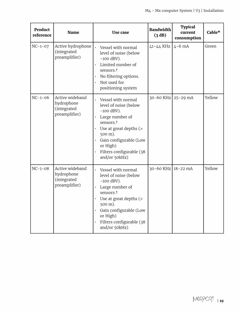
Understanding Receiver LEDs
Boot sequence
When you power on the receiver, the LEDS on the receiver must light up the following way:
• Hydrophone LEDs become blue / red / green.• LED in the letter A becomes blue / green / red, then stays red.• When data are emitted or received, ETH LED blinks green.
Hydrophone LEDs
The LEDs on the hydrophone inputs identify the type of hydrophone that is connected to thereceiver.
• Blue: passive hydrophone• Red: active hydrophone• No light: no configured hydrophone
| 22
M4 - Mx computer System | V3 | Servicing and Maintenance
Servicing and MaintenanceRead this section for troubleshooting and maintenance information.
Interference CheckYou can check if there is noise interfering with the reception of signals.
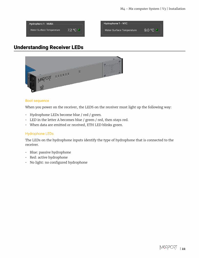
Spectrum Analyzer DisplayThe following picture explains the main parts of the spectrum analyzer page on Scala/Scala2.
1 Start/Stop spectrumanalyzer
2 Noise interference
3 Pulses of the sensors (PRP)
4 Narrow band/HDTE signals
5 Door sounder signals
6 Pause spectrum analyzer
7 Select hydrophone
8 Drag to adjust color scale
9 Reset the Max line.
10 Marker: display frequency and levels of noise (dB)at the mouse pointer location on the graph.
11 Peak:
• RealTime: latest highest level of noise recorded.• Max: highest level of noise recorded since the
beginning of the spectrum.
12 Export recorded max, mean and real time noiselevels in a txt file.
13 • Dark blue line: maximum signal level• Cyan line: average signal level• White line: last received signal level
| 23

M4 - Mx computer System | V3 | Servicing and Maintenance
Checking Noise InterferenceYou can use the spectrum analyzer to check the noise level of the hydrophones and check forinterference.
About this taskSee Spectrum Analyzer Display on page 23 for details about the spectrum analyzer display.
Procedure
1. Click Menu > Expert Mode and enter the password copernic.
2. Again in the menu, click Receivers.
3. From the top right corner of the screen, click Spectrum.
4. Select the hydrophone you want to test. Only the hydrophones that are switched on aredisplayed. Select refresh to update the list.
5. From the top left corner of the screen, click Start Spectrum.
The graph at the bottom of the page shows three levels of noise in dBV:
1. RealTime (white): level of noise recorded in real time.2. Mean (cyan): mean recorded level of noise. It is useful to assess the noise floor.3. Max (dark blue): shows the latest highest level of noise recorded. It is useful to see on which
frequencies are the sensors.
The acceptable average level of noise depends on the conditions (distance from the sensor tothe hydrophone, fishing method, type of hydrophone). You can have better performance withthe following levels:
• Active wideband hydrophone with high/low gain: below -100 dBV• Active narrowband: NC-1-04 below -80 dBV / NC-1-07 below -100 dBv• Passive hydrophone: below -110 dBV
| 24

M4 - Mx computer System | V3 | Servicing and Maintenance
6. To see the maximum, mean and real time measures of noise level at a specific frequency, selectMarker on the left side of the screen and move the mouse over the graph.
Frequency and levels of noise (dB) at the mouse pointer location are displayed under Marker.
7. Under Peak, you can check:
• RealTime: the latest highest level of noise recorded.• Max.: the highest level of noise recorded since the beginning of the spectrum.
8. Check that there is more than 12dBV between the maximum noise level (dark blue line) and theaverage noise level (light blue line) on the peak of sensor frequencies.
9. If you changed the configuration of the hydrophone or sensors, click Reset Max to reset thedark blue line showing the maximum level of noise.
10. To save data recorded by the spectrum in a *.txt file, click Save FFT.
The FFT file lists for the entire bandwidth used by the hydrophone (frequencies are in Hz) themaximum and mean levels of noise since the FFT export has started and the last real time levelof noise before the export (dBV).
11. When you have enough data, click Stop Spectrum.
Checking Noise InterferenceUse the spectrum analyzer to check the noise level of the hydrophones and check for interference.
Procedure
1. Click Add to create a new page on which you will add the spectrum analyzer(s).
2. Right-click the IP address of the receiver in the status bar and click Start Spectrum.
3. Open the control panels and go to the Mx panel.
4. Go to Hydrophone data, then drag and drop Spectrum data to a page. These data appear onlywhen the spectrum has been started.
| 25

M4 - Mx computer System | V3 | Servicing and Maintenance
5. The spectrum analyzer is displayed. You can display up to 6 spectrum analyzers at the sametime. Below is an example of a page with two spectrum analyzers.
The FFT plot shows three levels of noise in dBV:
1. RealTime (white): level of noise recorded in real time.2. Mean (cyan): mean recorded level of noise. It is useful to assess the noise floor.3. Max (dark blue): shows the latest highest level of noise recorded. It is useful to see on which
frequencies are the sensors.
The acceptable average level of noise depends on the conditions (distance from the sensor tothe hydrophone, fishing method, type of hydrophone). You can have better performance withthe following levels:
• Active wideband hydrophone with high/low gain: below -100 dBV• Active narrowband: NC-1-04 below -80 dBV / NC-1-07 below -100 dBv• Passive hydrophone: below -110 dBV
6. Scroll on the frequency or dBV scales to zoom in and out.
7. Under Peak, you can check:
| 26

M4 - Mx computer System | V3 | Servicing and Maintenance
• RealTime: the latest highest level of noise (dBV)recorded and its frequency.
• Max: the highest level of noise recorded since thebeginning of the spectrum and its frequency.
8. Check that there is more than 12 dBV between the maximum noise level (dark blue line) and theaverage noise level (cyan line) on the peak of sensor frequencies.
9. If you changed the configuration of the hydrophone or sensors, right-click the graph and clickReset Max to reset the dark blue line showing the maximum level of noise.
10. To check the maximum, mean and real time measures of noise level at specific frequencies:
a) Right-click the FFT plot and click FFT Marker.b) Click and drag the marker at a specific point.
Frequency and levels of noise at the marker position are displayed on the right side of thegraph.
11. Right-click the spectrum and click Pause if needed.
12. To save data recorded by the spectrum in a *.txt file, right-click the FFT plot and click SaveFFT.
The FFT file lists for the entire bandwidth used by the hydrophone (frequencies are in Hz) themaximum and mean levels of noise since the FFT export has started and the last real time levelof noise before the export (dBV).
| 27

M4 - Mx computer System | V3 | Servicing and Maintenance
13. Right-click the spectrum analyzer and click Hide FFT to hide the FFT plot.
14. Right-click the IP address of the receiver in the status bar and click Stop Spectrum.
| 28
M4 - Mx computer System | V3 | Servicing and Maintenance
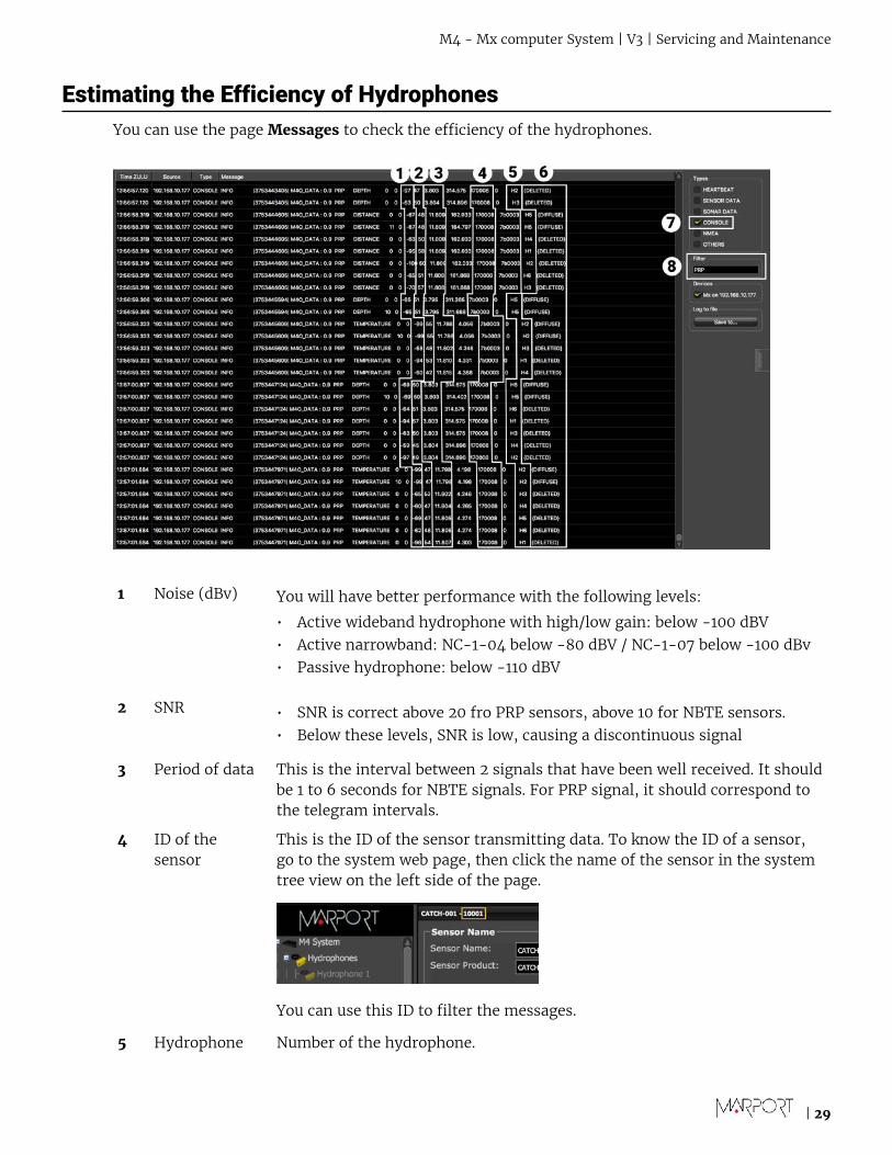
Estimating the Efficiency of HydrophonesYou can use the page Messages to check the efficiency of the hydrophones.
1 Noise (dBv) You will have better performance with the following levels:
• Active wideband hydrophone with high/low gain: below -100 dBV• Active narrowband: NC-1-04 below -80 dBV / NC-1-07 below -100 dBv• Passive hydrophone: below -110 dBV
2 SNR • SNR is correct above 20 fro PRP sensors, above 10 for NBTE sensors.• Below these levels, SNR is low, causing a discontinuous signal
3 Period of data This is the interval between 2 signals that have been well received. It shouldbe 1 to 6 seconds for NBTE signals. For PRP signal, it should correspond tothe telegram intervals.
4 ID of thesensor
This is the ID of the sensor transmitting data. To know the ID of a sensor,go to the system web page, then click the name of the sensor in the systemtree view on the left side of the page.
You can use this ID to filter the messages.
5 Hydrophone Number of the hydrophone.
| 29

M4 - Mx computer System | V3 | Servicing and Maintenance
6 Autoswitchselection
• DIFFUSE: Hydrophone chosen by the autoswitch. The chosenhydrophone is the one having the higher SNR and least variation of data.Received data are used in Scala/Scala2.
• DELETED: Data are received but they are not used in Scala/Scala2.
7 Console Select to see hydrophone messages.
8 Filter Use to filter messages.
| 30

M4 - Mx computer System | V3 | Servicing and Maintenance
TroubleshootingRead this section to know how to solve common problems.
No Internet Access
You cannot connect to the internet or see the system control panel page on Firefox web browser.
The order of the computer networks is wrong.
1. From the top left corner of the screen, click Apple Menu > System Preferences > Network.2. Make sure that the network called Ethernet 2 is at the top of the list, then is followed by the
network called Ethernet 1.
3. If not, to change the order click the tooth wheel icon at the bottom of the list and select SetService Order.
Antifouling System Causes Interferences
Sonihull™ Ultrasonic Antifouling System causes important noise interference. You can see below anexample of spectrum on a hydrophone when Sonihull™ system is off (1) and when it is switched on(2).
You need to switch off Sonihull™ system while fishing.
| 31

M4 - Mx computer System | V3 | Servicing and Maintenance
Giving Remote Access to the ComputerIf you have an issue with the system, you may need to give remote access to the computer to thesupport team with TeamViewer application.
Before you beginYou need to have access to a good internet connection.
Procedure
1. From the Launchpad or Dock, click TeamViewer.
2. Check that you have the message Ready to connect at the bottom left corner of TeamViewer. Ifthe message is Not ready it means you have no internet connection.
3. You can give access to your computer to the support team by giving them the ID and Passworddisplayed under Allow Remote Control.
Recording Audio FilesIf there are issues with the reception of sensor data or with noise interference, the support servicemay need a recording of the system noise in order to analyze it.
Procedure
1. From the lower right corner of Scala/Scala2 window, right-click the receiver name, then clickRecord WAV Files.
The receiver name becomes yellow. The recording lasts 180 seconds.
2. Open the control panels and go to the Mx panel. Click the menu icon next to the name of thereceiver and click Record Wave file.
3. When the recording is finished, click OK to download it.
The audio file is saved in:
4. Send the recording to Marport support service for a diagnosis.
| 32

M4 - Mx computer System | V3 | Servicing and Maintenance
Support ContactYou can contact your local dealer if you need maintenance on your Marport products. You can alsoask us at the following contact details:
FRANCE
Marport France SAS
8, rue Maurice Le Léon
56100 Lorient, France
ICELAND
Marport EHF
Fossaleyni 16
112 Reykjavik, Iceland
NORWAYMarport Norge A/S
Breivika Industrivei 69
6018 Ålesund, Norway
SOUTH AFRICAMarport South Africa
Cape Town, Western Cape
11 Paarden Eiland Road
Paarden Eiland, 7405
SPAIN
Marport Spain SRL
Camino Chouzo 1
36208 Vigo (Pontevedra), Spain
USA
Marport Americas Inc.
12123 Harbour Reach Drive, Suite 100
Mukilteo, WA 98275, USA
| 33

M4 - Mx computer System | V3 | Appendix
AppendixFrequency Plan
It is important to carefully plan the setup of your sensors before adding them to the system. Youcan create a table with a list of frequencies and complete it when you add sensors.
Boat & Channel Codes
This list shows the standard frequencies for PRP telegrams. When you configure boat codes, makesure to respect the correct interval between frequencies (see table above).
Codes
BC/CH Frequency FID (Scanmar)
C-1/CH1 42833 45
C-1/CH2 41548 32
C-1/CH3 41852 35
C-1/CH4 40810 25
C-1/CH5 42500 42
C-1/CH6 43200 49
C-2/CH1 42631 43
C-2/CH2 41417 31
C-2/CH3 41690 33
C-2/CH4 40886 26
C-2/CH5 42300 40
C-2/CH6 43100 48
C-3/CH1 42429 41
C-3/CH2 41285 30
C-3/CH3 41548 32
C-3/CH4 40970 27
C-3/CH5 42100 38
C-3/CH6 43000 47
C-4/CH1 42226 39
C-4/CH2 41852 35
C-4/CH3 41417 31
C-4/CH4 41160 29
| 34

M4 - Mx computer System | V3 | Appendix
C-4/CH5 42700 44
C-4/CH6 43300 50
C-5/CH1 42024 37
C-5/CH2 41690 33
C-5/CH3 41285 30
C-5/CH4 41060 28
C-5/CH5 42900 46
C-5/CH6 43400 51
C-6/CH1 39062 3
C-6/CH2 39375 7
C-6/CH3 39688 11
C-6/CH4 40000 15
C-6/CH5 40312 19
C-6/CH6 40625 23
C-7/CH1 38906 1
C-7/CH2 39219 5
C-7/CH3 39531 9
C-7/CH4 39844 13
C-7/CH5 40156 17
C-7/CH6 40469 21
| 35

M4 - Mx computer System | V3 | Appendix
Frequencies and intervals
The diagrams below show the bandwidth of the different types of Marport sensors and intervalsyou must respect when adding other sensors.
Figure 1: PRP sensors (e.g. Catch sensor, Trawl Speed, Spread sensor...)
Example: If the frequency of the sensor is 40kHz, there should be no sensors between 39.9-40kHzand 40-40.1kHz.
Figure 2: NBTE sensors (e.g. Speed Explorer, Trawl Explorer, Catch Explorer, Door Sounder)
Example: If the frequency of the sensor is 40kHz, there should be no sensors between 39.8-40kHzand 40-40.6kHz.
Figure 3: HDTE narrow band mode
Example: If the frequency of the sensor is 40kHz, there should be no sensors between 39.8-40kHzand 40-41kHz.
Figure 4: HDTE wide band mode
Example: If the frequency of the sensor is 40kHz, there should be no sensors between 39.8-40kHzand 40-42.6kHz.
Frequencyof the sensor
Bandwidth Mandatory distance withother sensors
Recommended distancewith other sensors
| 36

M4 - Mx computer System | V3 | Appendix
Examples of frequency allocations
• We recommend to allocate frequencies between 34 and 56 kHz for wideband hydrophones andbetween 41 kHz and 44 kHz for narrowband hydrophones.
• Echosounders are usually placed around 38 kHz, make sure to allow enough distance with them.
| 37

M4 - Mx computer System | V3 | Appendix
Exam
ple
of a
sys
tem
wit
h Sp
read
, Cat
ch, T
raw
l Spe
ed s
enso
rs a
nd S
peed
Exp
lore
r, C
atch
Exp
lore
r, H
DT
E an
d D
oor
Soun
der.
Exam
ple
of a
sys
tem
wit
h Sp
read
sen
sors
wit
h po
siti
onin
g, C
atch
sen
sors
, Tra
wl E
xplo
rer
and
Catc
h Ex
plor
er.
Exam
ple
of a
sys
tem
for
pur
se s
eini
ng, w
ith
a Se
ine
Expl
orer
and
dep
th S
eine
sen
sors
.
Ban
dwid
th
Man
dato
ry d
ista
nce
wit
h ot
her
sens
ors
Avo
id a
lloc
atin
g fr
eque
ncie
s be
twee
n 37
and
39
kH
z be
caus
e th
is r
ange
is g
ener
ally
use
d by
ech
osou
nde
rs.
| 38

Index | 39
IndexB
Boat code 34
C
Channel code 34
D
Data recording
Audio recording 32
F
FFT
Export 24Frequency plan 34
H
Hydrophone
Types 18
I
Internet
No access 31IP address 16
K
Keyboard
Virtual 12
M
Mac pro
Installation 14
N
Network
Mac Pro 16NMEA converter junction box 20Noise Interference 24
R
Receiver
Connecting to 20ETH LED 22H# LEDs 22Installation 14Lights 22
S
Sonihull
Interference 31Spectrum 23, 24
T
TeamViewer 32Technical specifications 11


![,-./(012345678 9:;?@ABC @ADE@AFG@2HIJKLMNOP 345=72QRSTUVWXYZ8 - [\]^_‘345ab9A(00cd e672fghijO kl()2mnA op2qrA>?stuv2wxyz{|P345ST2DY8 }~ •†12](https://img.pdfslide.net/doc/110x75/5f4e87a41ca651344d51d4c5/-012345678-9abc-adeafg2hijklmnop-34572qrstuvwxyz8-a345ab9a00cd.jpg)