Embed Size (px)
Citation preview

8/15/2019 015-IH-1009 (Flowlines)
http://slidepdf.com/reader/full/015-ih-1009-flowlines 1/9
KUWAIT OIL COMPANY KuSrnCu)
Specification umber
8/15/2019 015-IH-1009 (Flowlines)
http://slidepdf.com/reader/full/015-ih-1009-flowlines 2/9
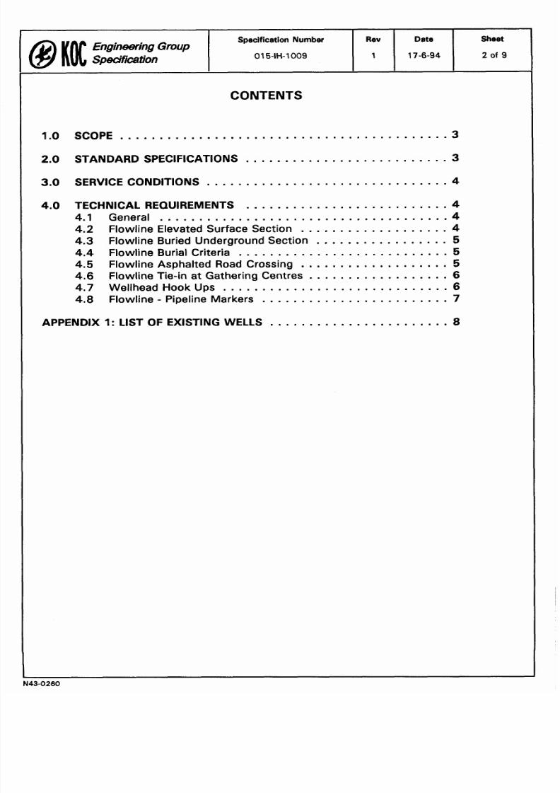
CONTENTS
ngineering
Group
SpecHcation
1.0
SCOPE
.0 STANDAR D SPECIFICATIONS
3
Specification Number
01
5 IH 1009
.0 SERVICE CO NDITIONS
4
.0
TECHNICAL REQUIREMENTS 4
.1 General 4
4.2 Flowline Elevated Surface Section 4
4.3
Flowline Buried Underground Section
5
4.4 Flowline Burial Criteria 5
4.5 Flowline Asphalted Road Crossing
5
4.6
Flowline Tie in at Gathering Centres 6
.7 Wellhead Hook Ups 6
4.8 Flowline ipeline Markers
7
Rev
1
PPENDIX 1: LIST OF EXISTING WELLS
Date
17 6 94
Sheet
2 of

8/15/2019 015-IH-1009 (Flowlines)
http://slidepdf.com/reader/full/015-ih-1009-flowlines 3/9
Specification umber
I
Rev
I ate
Sheet
1 0 SCOPE
1.1 This specification covers the design ma nufacture and supply of
flowlines for installation a t the Faci l i ty in Kuw ait.
1. 2 The flowlines shal l ful ly comply wi th al l relevant contractua l
requirements specified in the Scope of W ork and Technical Specification
of the C ontract .
2 0 ST ND RD SPECIFIC TIONS
2.1 The flow lines shall con form in design materials and performance
except where otherwise speci fied w i th th e current issue any
amendments of the fo l lowing prevai l ing on effect ive date of the
Contract:
2.1.1 International Standards
ASME B1 6.5
Pipe Flanges and Flanged Fittings
ASM E B 31.4 L i q u i d T r a n s m i s s i o n S y s t e m s f o r
Hydrocarbons Liquid Petroleum Gas
Anhydrous Ammonia and Alcohols
API 5L
Spe cification for Line Pipe
API 1 1 0 4
W elding o f Pipelines and Related F acilities
API 1 1 1 0 Pressure Testing Liquid Petroleum Pipelines
2.1.2 Engineering Grou p Spe cifications
0 15-AH-10 0 1
Basic Design Criteria
0 15-AH-10 0 2
International Codes and Standards
0 15-IH-10 01 Pipeline Con struction
0 15-IH -100 2 Pipeline Design
0 15-IH-10 05 Pipeline Dew atering and Drying
0 15- IH-1008
Pipeline Field Welding Non -Sour Service
0 15-IH -101 0 External Coating o f Line Pipe w it h Coal Tar
Enamel
0 15- IH-1012
Pipeline Field Jo int Co ating
8/15/2019 015-IH-1009 (Flowlines)
http://slidepdf.com/reader/full/015-ih-1009-flowlines 4/9
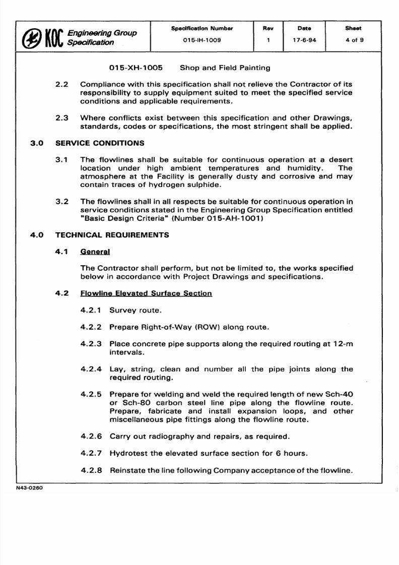
015-XH-1005 Shop and Field Painting
2 2
Compliance with this specification shall not relieve the Contractor of its
responsibility to supply equipment suited to meet the specified service
conditions and applicable requirements.
2.3
Where conflicts exist between this specification and other Drawings,
standards, codes or specifications, the most stringent shall be applied.
3 0
SERVICE CONDITIONS
3.1
The flowlines shall be suitable for continuous operation at a desert
location under high ambient temperatures and humidity. The
atmosphere at the Facility is generally dusty and corrosive and may
contain traces of hydrogen sulphide.
3.2 The flowlines shall in all respects be suitable for continuous operation in
service conditions stated in the Engineering Group Specification entitled
Basic Design Criteria (Number 015-AH-1001
4 0
TECHNICAL REQUIREMENTS
4.1
General
The Contractor shall perform, but not be limited to, the works specified
below in accordance with Project Drawings and specifications.
4 2 Flowline Elevated Surface Section
Survey route.
Prepare Right-of-way (ROW) along route.
Place concrete pipe supports along the required routing at 12-m
intervals.
Lay, string, clean and number all the pipe joints along the
required routing.
Prepare for welding and weld the required length of new Sch-40
or Sch-80 carbon steel line pipe along the flowline route.
Prepare, fabricate and install expansion loops, and other
miscellaneous pipe fittings along the flowline route.
Carry out radiography and repairs, as required.
Hydrotest the elevated surface section for 6 hours.
Reinstate the line following Company acceptance of the flowline.
Sheet
4 of
O
n g i n ~ n g roup
Spedfication
Specification Number
01 5-IH-1009
Rev
1
ate
17-6-94
8/15/2019 015-IH-1009 (Flowlines)
http://slidepdf.com/reader/full/015-ih-1009-flowlines 5/9
Specification Number Rev ate Sheet
Engineering
Group
Speci fication
01 5 IH 1009 1 17 6 94 5
of
9
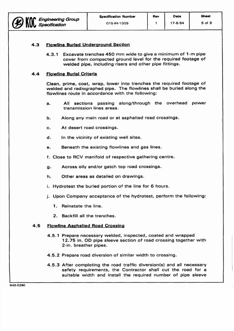
4.3
Flowline Buried Underuround Section
4.3.1
Excavate trenches 450 mm wide to give a minimum of -m pipe
cover from compacted ground level for the required footage of
welded pipe, including risers and other pipe fittings.
4.4
Flowline Burial Criteria
Clean, prime, coat, wrap, lower into trenches the required footage of
welded and radiographed pipe. The flowlines shall be buried along the
flowlines route in accordance with the following:
a. All sections passing alonglthrough the overhead power
transmission lines areas.
b.
Along any main road or at asphalted road crossings.
c. At desert road crossings.
d.
In the vicinity of existing well sites.
e.
Beneath the existing flowlines and gas lines.
f. Close to RCV manifold of respective gathering centre.
g. Across oily and/or gatch top road crossings.
h. Other areas as detailed on drawings.
i
Hydrotest the buried portion of the line for
6
hours.
j Upon Company acceptance of the hydrotest, perform the following:
1
Reinstate the line.
2. Backfill all the trenches.
4.5 Flowline As~hal ted oad Crossing
4.5.1 Prepare necessary welded, inspected, coated and wrapped
12.75 n. OD pipe sleeve section of road crossing together wi th
2-in, breather pipes.
4.5.2 Prepare road diversion of similar width t o crossing.
4.5.3
After completing the road traffic diversion s) and all necessary
safety requirements, the Contractor shall cut the road for a
suitable width and install the required number of pipe sleeve

8/15/2019 015-IH-1009 (Flowlines)
http://slidepdf.com/reader/full/015-ih-1009-flowlines 6/9
crossings. T w o numbers of pipe sleeves are t o be instal led at
each crossing: one for th e flow line t o be instal led and one spare.
Excavations for the above wo rk shall be suff ic ient ly deep up to
3 m) so that the top of the sleeve pipes shal l be at least 1 m
belo w the compacted ground level.
4.5.4 Install the prefabricated pipe sleeve installations and breather
pipes so that they shal l extend 3 m clear on each side of the
exist ing w idt h o f the road shoulders.
Engineering Group
Speci fication
4.5.5 After welding, radiography, coating, wrapping and inspection,
insert the flow line pipe through the pipe sleeve. Instal l matc hing
pipeline casing insulators at 1.3-m intervals, all along the length
of l ine pipe installed inside the pipe sleeve.
ate
17 6 94
4.5.6 Scale of f the open p orting betwee n the l ine pipe and pipe sleeve
at bo th ends of the pipe sleeve w i th end seals and also o ff bo th
ends spare pipe sleeve s).
heet
6 of 9
SpecificationNumber
015 IH 1009
4.5.7 Backfi ll all the trenches and reinstate the road to i ts original
condition, including asphalting.
Rev
1
4 6
Flow line Tie-in at Gatherina Centres
4.6.1 Construct f lowl ine t ie- in to the RCV m anifo ld at the respective
gathering centre. The flowline shal l be conne cted t o a RCV
man ifold point wh ich shal l be specified on the D rawings or onsite.
4.6.2 If required, f i rs t expose the old l inel l ines for about 75 -m length
upstream of RCV tie- in point. Then cu t the old l inel lines 2 -3 m
belowground, blank off and cap the old l inel l ines by welding.
Remove al l the cu tou t piping along w ith old r iser. The n ew ly laid
f lowl ine shall then be connected t o the same RCV manifo ld point
throu gh a n e w underground section and riser.
4.7
Wellhead Ho ok UDS
4.7.1 Wellhead Manifold
Fabricate as required a dual- or single-wellhead manifold and/or
m odify th e existing single to du al wellhead m anifold.
4.7.2 Surface Safety Man ifold
Fabricate as required a dual or single surface safety manifold,
and/or m odify the existing t o dual surface safety manifold.

8/15/2019 015-IH-1009 (Flowlines)
http://slidepdf.com/reader/full/015-ih-1009-flowlines 7/9
4.7.3 Tie-in of Wellhead and Surface Manifold to Flowline
a. Lay, string and weld approximately 100 m of 4-in. or 6-in.,
Sch-80 or Sch-40 pipe between the wellhead manifod and
surface safety manifold, and connect the two manifold to
the newly laid flowline.
b.
Clean, prime, coat, wrap, lower into trenches welded and
radiographed pipe as above. Then, backfill the trenches.
4.7.4 Burn-Off Pit BOP) Line
a. Lay, string, prepare for welding and weld approximately
300 m of 4-in., Sch-40 pipe.
b. Excavate 450-m wide minimum) trenches to give a
minimum of 2-m pipe cover for a total of approximately 75
m.
c. Clean, prime, coat, wrap, lower into trenches
approximately 75 m of the BOP line, and then backfill the
trenches. The remainder is to be laid on surface.
d. Connect the BOP line to the surface safety manifold.
e.
Route the end of the BOP line, through a BOP 12
m
in
diameter with the surrounding 3-m-high gatch wall.
4 8
lowline Pioeline Markers
Install pipeline markers and signs every 500 m throughout the length of
the flowline, whether buried underground or elevated on supports. In
addition, install pipeline markers and signs wherever the flowline enters
the ground and wherever
t
reappears aboveground.
8/15/2019 015-IH-1009 (Flowlines)
http://slidepdf.com/reader/full/015-ih-1009-flowlines 8/9
o
Specification Number Rev ate Sheet
ngineering
Group
Spedfiction
015-IH-1009 17-6-94 8 of 9
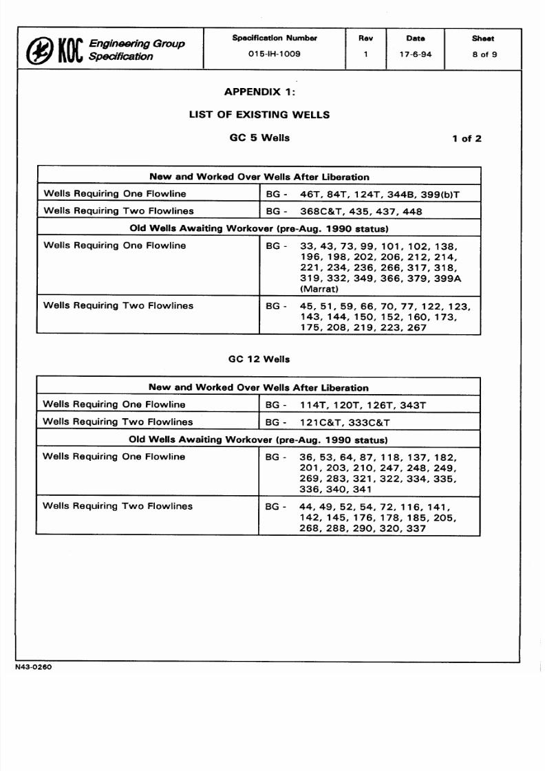
APPENDIX 1:
LIST
O
EXISTING WELLS
GC
5
Wells
New and Worked Over Wells After Liberation
Wells Requiring One Flowline
BG
46T, 84T, 124T, 344B, 399(b)T
Wells Requiring Two Flowlines BG 368C T, 435,437,448
Old Wells Awaiting Workover (pre-Aug. 199 status)
Wells Requiring One Flowline
BG
33,43, 73, 99, 101, 102, 138,
196, 198, 202, 206, 21 2, 214,
221, 234, 236, 266, 31 7, 31 8,
319,332,349,366, 379,399A
(Marrat)
Wells Requiring Two Flowlines
BG- 45, 51, 59, 66, 70, 77, 122, 123,
143, 144, 150, 152, 160, 173,
175, 208, 21 9, 223, 267
G 12
Wells
New and Worked Over Wells After Liberation
Wells Requiring One Flowline
BG
114T. 120T. 126T, 343T
Wells Requiring Two Flowlines BG
121C T, 333C T
Old Wells Awaiting Workover (pre-Aug.
199
status)
Wells Requiring One Flowline BG-
36,53,64,87, 118, 137, 182,
201, 203, 210, 247, 248, 249,
269, 283, 321, 322, 334, 335,
336,340,341
Wells Requiring Two Flowlines BG-
44,49,52, 54,72, 116, 141,
142, 145, 176, 178, 185, 205,
268, 288, 290, 320,337
8/15/2019 015-IH-1009 (Flowlines)
http://slidepdf.com/reader/full/015-ih-1009-flowlines 9/9
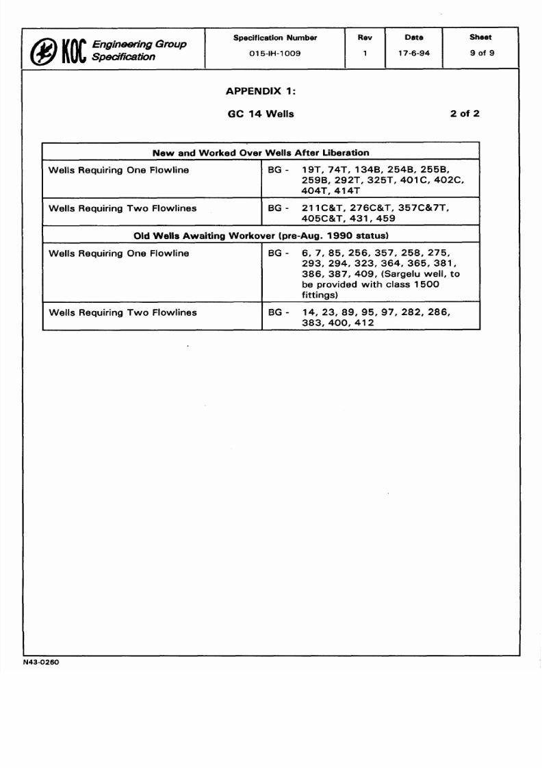
APPENDIX
1
G
14
Wells
Engineering Group
Ne w and Worked Over Wells After Liberation
Wells Requiring One Flowline
BG -
19T, 74T, 134B, 254B, 2558,
2598, 292T, 325T, 401C 402C,
404T, 414T
Wells Requiring Two Flowlines
BG
21 1C T, 276C T, 357C 7Tf
405C TT.431. 459
Specification Number
015-IH-1009
Old Wells Awa iting Workover pre-Aug. 199 status)
Wells Requiring One Flowline
BG -
6, 7 85, 256, 357, 258, 275,
293, 294, 323, 364, 365, 381,
386, 387, 409, (Sargelu well, to
be provided with class 1500
fittings)
Wells Requiring Two Flowlines
BG - 14, 23, 89, 95, 97, 282, 286,
383,400,412
Rev
1
Date
17-6-94
Sheet
9 of 9


![L15-Subsea Flowlines [Compatibility Mode]](https://img.pdfslide.net/doc/110x75/577d2dba1a28ab4e1eae2fd7/l15-subsea-flowlines-compatibility-mode.jpg)