Embed Size (px)
Citation preview
01542KNX 1-channel DALI gateway
Installer manual
2
3
1. General ………………………………………………………………………………………………………………………………………………………………………………… 4
1.1 Using the product manual ………………………………………………………………………………………………………………………………………………………… 41.1.1 Structure of the product manual ……………………………………………………………………………………………………………………………………………………………41.1.2 Notes ……………………………………………………………………………………………………………………………………………………………………………………………4
1.2 Product and functional overview …………………………………………………………………………………………………………………………………………………… 51.2.1 Emergency lighting tests ……………………………………………………………………………………………………………………………………………………………………6
1.3 General information on DALI and standards ……………………………………………………………………………………………………………………………………… 6
2. Device technology ………………………………………………………………………………………………………………………………………………………………… 7
2.1 Technical datai ……………………………………………………………………………………………………………………………………………………………………… 7
2.2 Connection diagram ………………………………………………………………………………………………………………………………………………………………… 9
2.3 Mounting and installation …………………………………………………………………………………………………………………………………………………………… 10
2.4 Description of inputs and outputs ………………………………………………………………………………………………………………………………………………… 11
2.5 Manual operation …………………………………………………………………………………………………………………………………………………………………… 112.5.1 Display elements …………………………………………………………………………………………………………………………………………………………………………… 12
3. Commissioning ……………………………………………………………………………………………………………………………………………………………………… 13
3.1 Overview …………………………………………………………………………………………………………………………………………………………………………… 13
3.2 Parameters …………………………………………………………………………………………………………………………………………………………………………… 153.2.1 General parameter window ……………………………………………………………………………………………………………………………………………………………… 163.2.2 DALI output A parameter window ……………………………………………………………………………………………………………………………………………………… 19
3.2.2.1 A DALI configuration parameter window …………………………………………………………………………………………………………………………………………………… 193.2.3 A Output parameter window …………………………………………………………………………………………………………………………………………………………… 22
3.2.3.1 A Output: State parameter window ………………………………………………………………………………………………………………………………………………………… 293.2.3.2 A Output: Fault parameter window ………………………………………………………………………………………………………………………………………………………… 323.2.3.3 A Output: Functions (Turn off brightness/Burn-in/Slave offset/Partial failure) parameter window …………………………………………………………………………………… 37
3.2.4 A template group x/ballast x parameter window) …………………………………………………………………………………………………………………………………… 433.2.4.1 A Status template (group x/ballast x) parameter window ………………………………………………………………………………………………………………………………… 523.2.4.2 A Fault template (group x/ballast x) parameter window ………………………………………………………………………………………………………………………………… 543.2.4.3 A Functions template (group x/ballast x) (Forced operation/ Block/Burn-in/Partial failure) parameter window …………………………………………………………………… 573.2.4.4 A Slave template (group x/ballast x) parameter window ………………………………………………………………………………………………………………………………… 623.2.4.5 A Staircase lighting template (group x/ballast x) parameter window …………………………………………………………………………………………………………………… 67
3.2.5 X groups or X ballasts parameter window ……………………………………………………………………………………………………………………………………………… 733.2.5.1 X groups/Group x or X ballasts/Ballast x / status parameter window …………………………………………………………………………………………………………………… 763.2.5.2 X groups/Group x or X ballasts/Ballast x / fault parameter window …………………………………………………………………………………………………………………… 773.2.5.3 X groups/Group x or X ballasts//ballast x / functions (Forced operation/Block/Burn-in/Partial failure) parameter window……………………………………………………… 783.2.5.4 X groups/Group x or X ballasts/Ballast x / slave parameter window …………………………………………………………………………………………………………………… 793.2.5.5 X groups/Group x or X ballasts/Ballast x / staircase lighting parameter window …………………………………………………………………………………………………… 80
3.2.6 A lighting converter parameter window ………………………………………………………………………………………………………………………………………………… 813.2.6.1 A lighting converter/Emergency light template parameter window …………………………………………………………………………………………………………………… 853.2.6.2 A lighting converter/Emergency light x parameter window ……………………………………………………………………………………………………………………………… 91
3.2.7 A scenes parameter window …………………………………………………………………………………………………………………………………………………………… 923.2.7.1 A scenes/Scene x parameter window ……………………………………………………………………………………………………………………………………………………… 93
3.3 Group objects ……………………………………………………………………………………………………………………………………………………………………… 953.3.1 Summary of group objects ……………………………………………………………………………………………………………………………………………………………… 953.3.2 Group objects General …………………………………………………………………………………………………………………………………………………………………… 983.3.3 Output A group objects …………………………………………………………………………………………………………………………………………………………………… 993.3.4 Group x/Ballast x group objects …………………………………………………………………………………………………………………………………………………………1213.3.5 Lighting converter x group objects ………………………………………………………………………………………………………………………………………………………127
4. Planning and application ……………………………………………………………………………………………………………………………………………………… 132
4.1 DALI addressing ………………………………………………………………………………………………………………………………………………………………… 132
4.2 Lamp and ballast monitoring …………………………………………………………………………………………………………………………………………………… 132
4.3 Exchange of DALI devices ……………………………………………………………………………………………………………………………………………………… 133
4.4 Function circuit diagrams and priorities ………………………………………………………………………………………………………………………………………… 133
4.5 DALI dimming curve ……………………………………………………………………………………………………………………………………………………………… 1364.5.1 DALI (logarithmic) curve ……………………………………………………………………………………………………………………………………………………………………1364.5.2 KNX (linear) curve …………………………………………………………………………………………………………………………………………………………………………138
4.6 Time sequences in the gateway ………………………………………………………………………………………………………………………………………………… 1394.6.1 DALI fade times ……………………………………………………………………………………………………………………………………………………………………………1394.6.2 Timed progression of the staircase lighting function ……………………………………………………………………………………………………………………………………140
A. Appendix …………………………………………………………………………………………………………………………………………………………………………… 141
A.1 8-bit scene code table (group object 33) ……………………………………………………………………………………………………………………………………… 141
A.2 Fault addressed "Request" (no. 21) code table ……………………………………………………………………………………………………………………………… 143
A.3 Fault addressed "Feedback" (no. 21) code table …………………………………………………………………………………………………………………………… 144
Contents
4
General
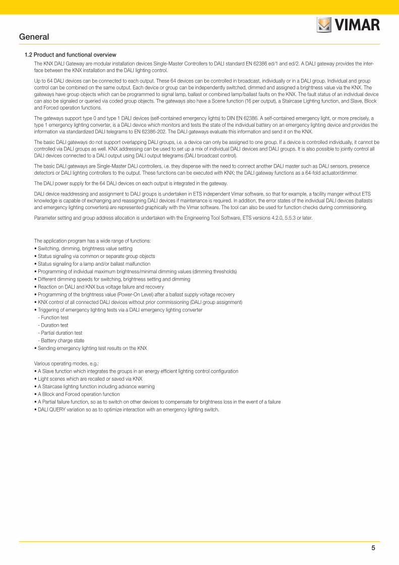
1. GeneralThis manual provides detailed technical information concerning the KNX DALI Gateway. They can be used to control a variety of DALI lamps individually or in groups on a DALI output via KNX bus. Lots of small groups in individual offices as well as large lights for area lighting can be combined in a gateway as required. The installation, programming, commissioning and use of the device are described using examples.
The DALI gateways are used to control DALI equipment such as ballasts, transformers or LED converters with device type 0 DALI interfaces to DIN EN 62386, via KNX. DALI self-contained emergency lights with individual batteries (device type 1) to EN 62386 (Part 202) can also be integrated.
The DALI gateways themselves provide no functionality in terms of the emergency lighting regulations, e.g. logging functions or other associated stipulated functions. They serve as an intelligent mediator between KNX and DALI.
Using group objects, the various mandatory emergency lighting tests, e.g. function or duration tests, can be triggered via KNX bus and the results provided in the same way. This information can then be used for higher-level management of the emergency lighting, which triggers at prescribed times and captures, saves or logs the result provided via KNX on the gateway.
The DALI gateways combine both the internationally standardized and open standards in the DALI standard (EN 62386) and the KNX home and building electronic systems standards (ISO/IEC 14543-3 and EN 50090).
1.1 Using the product manualThis manual is divided into the following chapters:• Chapter 1 General• Chapter 2 Device technology• Section 3 Commissioning• Section 4 Planning and application• Chapter A Appendix
1.1.1 Structure of the product manual
All parameters are described in section 3.
1.1.2 Notes
Notes and safety instructions are represented as follows in this manual:
Note
Tips for usage and operation
Examples
Application examples, installation examples, programming examples
Important
These safety instructions are used as soon as there is danger of a malfunction without risk of damage or injury.
AttentionThese safety instructions are used as soon as there is danger of a malfunction without risk of damage or injury.
DangerThese safety instructions are used if there is a danger to life and limb with inappropriate use.
DangerThese safety instructions are used if there is an extreme danger to life with inappropriate use.
5
General
1.2 Product and functional overviewThe KNX DALI Gateway are modular installation devices Single-Master Controllers to DALI standard EN 62386 ed/1 and ed/2. A DALI gateway provides the inter-face between the KNX installation and the DALI lighting control.
Up to 64 DALI devices can be connected to each output. These 64 devices can be controlled in broadcast, individually or in a DALI group. Individual and group control can be combined on the same output. Each device or group can be independently switched, dimmed and assigned a brightness value via the KNX. The gateways have group objects which can be programmed to signal lamp, ballast or combined lamp/ballast faults on the KNX. The fault status of an individual device can also be signaled or queried via coded group objects. The gateways also have a Scene function (16 per output), a Staircase Lighting function, and Slave, Block and Forced operation functions.
The gateways support type 0 and type 1 DALI devices (self-contained emergency lights) to DIN EN 62386. A self-contained emergency light, or more precisely, a type 1 emergency lighting converter, is a DALI device which monitors and tests the state of the individual battery on an emergency lighting device and provides the information via standardized DALI telegrams to EN 62386-202. The DALI gateways evaluate this information and send it on the KNX.
The basic DALI gateways do not support overlapping DALI groups, i.e. a device can only be assigned to one group. If a device is controlled individually, it cannot be controlled via DALI groups as well. KNX addressing can be used to set up a mix of individual DALI devices and DALI groups. It is also possible to jointly control all DALI devices connected to a DALI output using DALI output telegrams (DALI broadcast control).
The basic DALI gateways are Single-Master DALI controllers, i.e. they dispense with the need to connect another DALI master such as DALI sensors, presence detectors or DALI lighting controllers to the output. These functions can be executed with KNX; the DALI gateway functions as a 64-fold actuator/dimmer.
The DALI power supply for the 64 DALI devices on each output is integrated in the gateway.
DALI device readdressing and assignment to DALI groups is undertaken in ETS independent Vimar software, so that for example, a facility manger without ETS knowledge is capable of exchanging and reassigning DALI devices if maintenance is required. In addition, the error states of the individual DALI devices (ballasts and emergency lighting converters) are represented graphically with the Vimar software. The tool can also be used for function checks during commissioning.
Parameter setting and group address allocation is undertaken with the Engineering Tool Software, ETS versions 4.2.0, 5.5.3 or later.
The application program has a wide range of functions:• Switching, dimming, brightness value setting• Status signaling via common or separate group objects• Status signaling for a lamp and/or ballast malfunction• Programming of individual maximum brightness/minimal dimming values (dimming thresholds)• Different dimming speeds for switching, brightness setting and dimming• Reaction on DALI and KNX bus voltage failure and recovery• Programming of the brightness value (Power-On Level) after a ballast supply voltage recovery• KNX control of all connected DALI devices without prior commissioning (DALI group assignment)• Triggering of emergency lighting tests via a DALI emergency lighting converter
- Function test- Duration test- Partial duration test- Battery charge state
• Sending emergency lighting test results on the KNX
Various operating modes, e.g.:• A Slave function which integrates the groups in an energy efficient lighting control configuration• Light scenes which are recalled or saved via KNX• A Staircase lighting function including advance warning• A Block and Forced operation function• A Partial failure function, so as to switch on other devices to compensate for brightness loss in the event of a failure• DALI QUERY variation so as to optimize interaction with an emergency lighting switch.
6
General
1.2.1 Emergency lighting tests
The art. 01542 acts as a gateway between self-contained emergency lighting systems and a KNX building automation system. This allows DALI-based emer-gency lighting to IEC 62386-202 to be controlled and monitored with a KNX control panel.
A DALI device to IEC 62386-202 (device type 1), for self-contained emergency lights, is described in this manual in shortened form as an emergency lighting converter.
The gateway itself provides no functionality in terms of the emergency lighting regulations, e.g. logging or other associated stipulated functions. It is used exclusively as a gateway between KNX group objects and DALI commands.
The various mandatory tests for emergency lighting are controlled by KNX group objects. The test sequence is subsequently monitored by KNX group ob-jects, and the results are signaled by further group objects on the KNX.
A further option for emergency lighting tests is the use of an automated test interval controlled by the DALI emergency lighting converter itself. The interval duration is defined by KNX parameters. KNX group objects transmit the results.
Function test
The function test is implemented by the emergency lighting converter itself. The test is requested at a parametrizable interval in the emergency lighting con-verter or by a KNX group object. The test covers the functional security of the emergency lighting converter electronics and correct operation of a lamp and a switch-over device for an individual battery.
Duration test
The duration test is implemented on the basis of IEC 62386-202 and is used to determine whether the individual battery supplies the system within the limits of the rated operating duration in emergency lighting operation.
Partial duration test
The gateway controls the partial duration test with the aid of the DALI device duration test. This is possible because a partial duration test is not stipulated or described by the standards. It is just an additional option to improve the operation readiness of emergency lighting simply and quickly without fully discharging the battery.
The partial duration test is a duration test which is terminated by the gateway after a set time. Therefore, for the test to run there must be a connection be-tween the gateway and the emergency lighting converter. If the gateway is unable to stop the test, it runs for the full duration.
Inhibit/rest mode
Rest mode is a state in which the emergency light is switched off during its emergency lighting operation.
Inhibit mode is a timed emergency lighting converter state in which the emergency light does not switch to emergency operation in the event of a mains volt-age failure.
DangerIn both cases, the emergency light no longer fulfils its safety function and remains off.
For this reason, use this function with great care. It can be helpful to use Inhibit/rest mode during the construction phase when the power supply is often switched off, to prevent the emergency lighting battery from constantly charging/discharging and thus conserve the emergency light.
1.3 General information on DALI and standardsThe requirements for modern lighting technology are extremely varied. Historically, lighting was only required for visual tasks, but nowadays there is a focus on factors such as comfort, ambience, functionality and energy saving. Further-more, modern lighting systems are increasingly being incorporated into building installation facility management to monitor the status of the entire lighting system. The requirement is often for a complex lighting management system which meets the uses of the premises. All these requirements cannot be adequately met by traditional 1–10 V electrical installations, or only at considerable effort and cost. The DALI standard (EN 62386, formerly EN 60929) has emerged against this background in conjunction with leading manufacturers of lamp ballasts. It describes and defines the DALI (Digital Addressable Lighting Interface) digital interface for lighting technology equipment.
DALI has become established as an independent standard in the field of lighting technology. The range of ballasts, transformers, dimmers and relays with DALI interfaces has decisively influenced modern lighting technology.
Part 202 of DALI standard 62386 standardizes telegrams, which communicate with emergency lighting units (converters) in self-contained emergency lighting with individual batteries. These standardized DALI telegrams can be used to trigger emergency lighting tests (e.g. function or duration tests). The test results are provided on the DALI by the DALI emergency lighting converter.
This DALI technology allows cyclically required emergency lighting tests to be triggered via a higher-level building management control system and can also docu-ment the result.
7
2. Device technologyThe KNX DALI Gateway is a KNX modular installation device (MDRC) for installation in the distribution board on a 35 mm mounting rail.
It is a DALI Single-Master controller to DALI standard DIN EN 62386 Parts 101ed2 and 103ed1.
It supports type 0 and type 1 DALI operating devices with DALI interfaces to DIN EN 62386 and these can be integrated into a KNX building installation. The gateway connects to the bus via a KNX connection terminal on the device shoulders.
The DALI Gateways differ in the number of DALI outputs. They are equivalent, and each of them has the same technical properties and functions.
Up to 64 DALI devices can be connected to each DALI output. Both "normal" lamps (DALI type 0) and battery operated emergency lighting (DALI type 1) can be con-nected to the DALI output in a mixed configuration.
The lamps are variably controlled via KNX per DALI output via- Broadcast (all lamps jointly)- 16 lighting groups- 64 individual lamps- 16 scenes- 64 self-contained emergency lights
The fault status (lamps, ballasts or emergency lighting converters) of each DALI device or of the lighting group is sent on the KNX by a variety of KNX group objects.
In addition to the standard functions, e.g. switching, dimming and brightness value setting with the corresponding feedback, the DALI gateway has Staircase lighting, Scene, Slave, Forced operation and Block functions. The lighting groups or individual lamps can be integrated into an energy-efficient building automation system via a KNX presence detector or light controller.
Function, duration and partial duration tests and battery tests for emergency lighting systems with individual batteries to DIN EN 62386-202 can be triggered and stopped via KNX. The results are provided on the KNX.
The DALI gateway has a wide-range power supply input. No separate DALI power supply is required. The DALI power supply for 64 DALI devices per output is inte-grated into the DALI gateway.
The Vimar software permits commissioning (DALI) and diagnostics without the ETS.
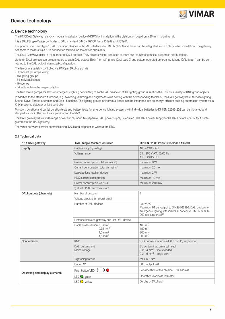
2.1 Technical data
KNX DALI gateway DALI Single-Master Controller DIN EN 62386 Parts 101ed2 and 103ed1
Supply Gateway supply voltage 100 – 240 V AC
Voltage range 85…265 V AC, 50/60 Hz110…240 V DC
Power consumption total via mains*) maximum 6 W
Current consumption total via mains*) maximum 25 mA
Leakage loss total for device*) maximum 2 W
KNX current consumption Maximum 10 mA
Power consumption via KNX Maximum 210 mW
*) at 230 V AC and max. load
DALI outputs (channels) Number of outputs 1
Voltage proof, short circuit proof
Number of DALI devices 230 V AC Maximum 64 per output to DIN EN 62386; DALI devices for emergency lighting with individual battery to DIN EN 62386-202 are supported.2)
Distance between gateway and last DALI device
Cable cross-section 0,5 mm2
0,75 mm2
1,0 mm2
1,5 mm2
100 m1)
150 m1)
200 m1)
300 m1)
Connections KNX KNX connection terminal, 0,8 mm Ø, single core
DALI outputs andMains voltage
Screw terminal, universal head0,2…4 mm2 fine stranded0,2…6 mm2 single core
Tightening torque Max. 0,6 Nm
Operating and display elements
Button DALI output test
Push button/LED For allocation of the physical KNX address
LED , green Operation readiness indicator
LED , yellow Display of DALI fault
Device technology
8
KNX DALI gateway DALI Single-Master Controller DIN EN 62386 Parts 101ed2 and 103ed1
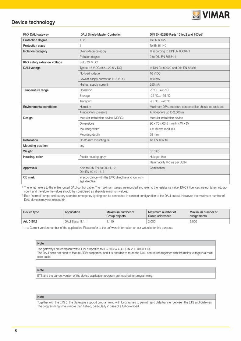
Protection degree IP 20 To EN 60529
Protection class II To EN 61140
Isolation category Overvoltage category III according to DIN EN 60664-1
Pollution degree 2 to DIN EN 60664-1
KNX safety extra low voltage SELV 24 V DC
DALI voltage Typical 16 V DC (9.5…22.5 V DC) to DIN EN 60929 and DIN EN 62386
No-load voltage 16 V DC
Lowest supply current at 11.5 V DC 160 mA
Highest supply current 250 mA
Temperature range Operation -5 °C…+45 °C
Storage -25 °C…+55 °C
Transport -25 °C…+70 °C
Environmental conditions Humidity Maximum 93%, moisture condensation should be excluded
Atmospheric pressure Atmosphere up to 2,000 m
Design Modular installation device (MDRC) Modular installation device
Dimensions 90 x 70 x 63.5 mm (H x W x D)
Mounting width 4 x 18 mm modules
Mounting depth 68 mm
Installation On 35 mm mounting rail To EN 60715
Mounting position any
Weight 0,13 kg
Housing, color Plastic housing, gray Halogen-free
Flammability V-0 as per UL94
Approvals KNX to DIN EN 50 090-1, -2DIN EN 50 491-5-2
Certification
CE mark In accordance with the EMC directive and low volt-age directive
1) The length refers to the entire routed DALI control cable. The maximum values are rounded and refer to the resistance value. EMC influences are not taken into ac-count and therefore the values should be considered as absolute maximum values.
2) Both "normal" lamps and battery operated emergency lighting can be connected in a mixed configuration to the DALI output. However, the maximum number of DALI devices may not exceed 64.
Device type Application Maximum number ofGroup objects
Maximum number ofGroup addresses
Maximum number ofassignments
Art. 01542 DALI Basic 1f /…* 1.119 2.000 2.000
* … = Current version number of the application. Please refer to the software information on our website for this purpose.
Note
The gateways are compliant with SELV properties to IEC 60364-4-41 (DIN VDE 0100-410).The DALI does not need to feature SELV properties, and it is possible to route the DALI control line together with the mains voltage in a multi-core cable.
Note
ETS and the current version of the device application program are required for programming.
Note
Together with the ETS 5, the Gateways support programming with long frames to permit rapid data transfer between the ETS and Gateway. The programming time is more than halved, particularly in case of a full download.
Device technology
9
Device technology
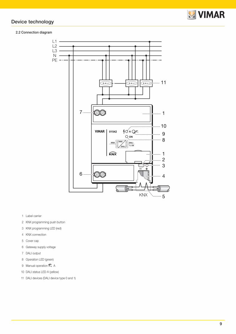
2.2 Connection diagram
01542 A
ON
KNX KNX DALI1 x 64DALI
D A L ID A L ID A L I
L1L2L3NPE
KNX
1
11
10
89
7
6
1
32
4
5
1 Label carrier
2 KNX programming push button
3 KNX programming LED (red)
4 KNX connection
5 Cover cap
6 Gateway supply voltage
7 DALI output
8 Operation LED (green)
9 Manual operation A
10 DALI status LED A (yellow)
11 DALI devices (DALI device type 0 and 1)
10
Device technology
2.3 Mounting and installation
The gateways are modular installation devices for installation in the distribution board on 35 mm mounting rails to EN 60715. They can be installed in any mounting position.Electrical connection is via screw terminals. Connection to the KNX is via the supplied KNX connection terminal. The terminal assignment is located on the housing.The devices are ready to operate when the KNX voltage and gateway supply voltage are applied.The devices must be accessible for the purposes of operation, testing, visual inspection, maintenance and repair in compliance with VDE 0100-520.
Commissioning requirementGateway commissioning requires a PC with ETS and a KNX interface, e.g. USB or IP.DALI device group assignment and emergency lighting converter configuration are carried out with the Vimar software.The emergency lighting battery must be charged in order to commission the DALI emergency lighting converter. Commissioning is not possible during emergency lighting operation.
Important
Acceptance of the emergency lighting monitoring must be discussed with the relevant approval agency.
Mounting and commissioning may only be carried out by electrical specialists. The applicable standards, directives, regulations and specifications for the country in question must be observed when planning and setting up electrical installations and security systems for intrusion and fire detection.
• Protect the device from moisture, dirt and damage during transport, storage and operation.
• Do not operate the device outside the specified technical data.
• Only operate the device in a closed housing (distribution board).
• Switch off the device supply voltage before mounting.
Danger
To avoid dangerous touch voltages which originate through feedback from differing phase conductors, all poles must be disconnected when extending or modifying the electrical connections.
Danger
DALI is not a SELV (Safety Extra Low Voltage) system, therefore DALI control cables and the 230 V power supply cable must be routed into a single cable. Observe the corresponding installation regulations.
Manual operationThe gateways have a manual operation option to switch DALI lamps on and off at the outputs. However this excludes DALI single battery lamps, which cannot be manually operated.
Supplied stateThe device is supplied with the physical address 15.15.255. The application program is preloaded. It is therefore only necessary to load group addresses and parameters during commissioning.However, the complete application program can be reloaded if required. Longer downtime may result if the application program is changed or after a discharge.
Allocation of the physical addressThe physical address is assigned and programmed in ETS.The device shoulder features a push button for allocation of the physical device address. The red LED lights up after the button has been pushed. It switches off as soon as ETS has assigned the physical address or the button is pressed again.
Download responseBecause of the complexity of the device, the progress bar for download may take up to 90 seconds to appear depending on the PC used.
CleaningIf devices become dirty, they can be cleaned using a dry cloth or a cloth dampened with a soapy solution. Corrosive agents or solutions must never be used.
MaintenanceThe device is maintenance-free. In the event of damage, e.g. during transport and/or storage, do not carry out any repairs.
11
Device technology
2.4 Description of inputs and outputs
Up to 64 devices with a DALI interface can be connected to the DALI output. The DALI gateway is a DALI master with integrated DALI power supply.
Important
Other DALI masters must not be connected to the gateway output.Connecting another master to the Single-Master system can cause communication malfunctions.
CautionOther DALI power supplies must not be connected to the gateway output.Connecting another DALI power supply can add to the DALI currents which in turn may irreparably damage the DALI input stages on the ballasts.Inadvertently connecting 230 V mains voltage to the DALI output will not destroy the DALI output stage as the output has built-in protection.
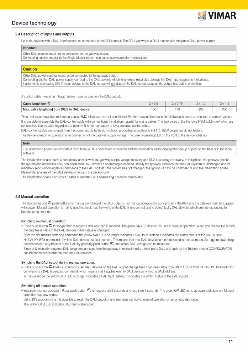
A control cable – maximum length below – can be used on the DALI output:
Cable length [mm2] 2 x 0,5 2 x 0,75 2 x 1,0 2 x 1,5
Max. cable length [m] from DG/S to DALI device 100 150 200 300
These values are rounded resistance values. EMC influences are not considered. For this reason, the values should be considered as absolute maximum values.It is possible to assemble the DALI control cable with conventional installation material for mains cables. The two cores of the five-core NYM 5x1.5 mm2 which are not required can be used regardless of polarity. It is not mandatory to lay a separate control cable.DALI control cables are isolated from the power supply by basic insulation properties according to EN 410. SELV properties do not feature.The device is ready for operation after connection of the gateway supply voltage. The green operating LED on the front of the device lights up.
Note
The initialization phase will terminate if more than 64 DALI devices are connected and the information will be displayed by group objects on the KNX or in the Vimar software.
The initialization phase starts automatically after download, gateway supply voltage recovery and KNX bus voltage recovery. In this phase, the gateway checks the system and addresses new, non-addressed DALI devices if addressing is enabled. Initially the gateway assumes that the DALI system is unchanged and im-mediately sends incoming KNX commands to the DALI, so that if the system has not changed, the lighting can still be controlled during the initialization phase. Meanwhile, analysis of the DALI installation runs in the background.The initialization phase also runs if Enable automatic DALI addressing has been deactivated.
2.5 Manual operation
The device has one push buttons for manual switching of the DALI outputs. For manual operation to work properly, the KNX and the gateway must be supplied with power. Manual operation is mainly used to check that the wiring of the DALI line is correct and to detect faulty DALI devices which are not responding to broadcast commands.
Switching on manual operation:• Press push button for longer than 2 seconds and less than 5 seconds. The green ON LED flashes. You are in manual operation. When you release the button,
the brightness value of the DALI devices initially stays unchanged.After the first manual switching command the yellow DALI LED no longer indicates a DALI fault. Instead it indicates the switch status of the DALI output.No DALI QUERY commands (cyclical DALI device queries) are sent. This means that new DALI devices are not detected in manual mode. As triggered switching commands can only be sent to the DALI by pressing push button , the actual DALI voltage can be measured.Since only manually triggered DALI telegrams are sent from the gateway in manual mode, a third-party DALI tool such as the Tridonic master CONFIGURATOR can be connected in order to read the DALI devices.
Switching the DALI output during manual operation:• Press push button briefly (< 2 seconds). All DALI devices on the DALI output change their brightness state from ON to OFF or from OFF to ON. This switching
command is a DALI broadcast command, which means that it applies even to DALI devices without a DALI address.In manual mode the yellow DALI LED no longer indicates a DALI fault. Instead it indicates the switch status of the DALI output.
Switching off manual operation:• You are in manual operation. Press push button for longer than 2 seconds and less than 5 seconds. The green ON LED lights up again and stays on. Manual
operation has now ended.Using ETS programming it is possible to retain the DALI output brightness value set during manual operation or set an updated value.The yellow DALI LED indicates DALI fault status again.
12
Triggering DALI addressing via the push button:• Press push button for longer than five seconds. This will not exit the current mode but will trigger DALI addressing. The yellow DALI LED flashes. DALI devices
without addresses are assigned the first free address. If the system detects devices with duplicate DALI addresses, it deduplicates them.Manual operation including triggering DALI addressing can be enabled or disabled via the Disable manual operation/Status group object (no. 2). The status of whether manual operation is disabled can be requested via the same group object. After a KNX voltage failure, the system reinstates the state prior to the failure. The timeout for manual operation before automatic exit is parametrizable. This time is retriggered after every manual operation.
Note
Vimar software functions are carried out during manual operation in order to ensure consistent commissioning.We recommend that you do not use the Vimar software and manual operation at the same time as the functions can have a mutual influence.
Note
KNX commands incoming during manual operation are not executed, but are processed in the background. Scene implementation and interim dimming values are not taken into consideration in the background in the simulation.Depending on the parametrization (see General parameter window), the system sets either the updated brightness value or the brightness value set in manual mode.
Note
The Forced operation and Block function of a group has a higher priority than manual operation, i.e. if a ballast or group with a particular brightness value is forcibly operated or blocked, it cannot be manually switched or dimmed. If the forced operation or block is reset in manual mode, the ballast or group stays at the current brightness value regardless of what it is programmed to do when forced operation ends, and only follows the next control command.
2.5.1 Display elements
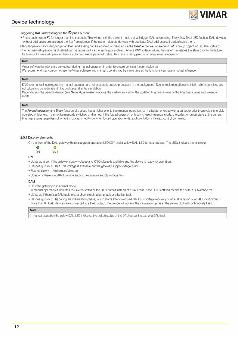
On the front of the DALI gateway there is a green operation LED (ON) and a yellow DALI LED for each output. The LEDs indicate the following:
ON DALI
ON• Lights up green if the gateway supply voltage and KNX voltage is available and the device is ready for operation.• Flashes quickly (5 Hz) if KNX voltage is available but the gateway supply voltage is not.• Flashes slowly (1 Hz) in manual mode.• Goes off if there is no KNX voltage and/or the gateway supply voltage fails.
DALI• Off if the gateway is in normal mode.
In manual operation it indicates the switch status of the DALI output instead of a DALI fault. If the LED is off this means the output is switched off.• Lights up if there is a DALI fault, e.g., a short circuit, a lamp fault or a ballast fault.• Flashes quickly (5 Hz) during the initialization phase, which starts after download, KNX bus voltage recovery or after elimination of a DALI short circuit. If
more than 64 DALI devices are connected to a DALI output, the device will not exit the initialization phase. The yellow LED will continuously flash.
Note
In manual operation the yellow DALI LED indicates the switch status of the DALI output instead of a DALI fault.
Device technology
13
Commissioning
3. CommissioningThe application program used to parametrize the KNX DALI gateway are:
Gateway DALI configurator softwareand the Engineering Tool Software ETS, version 4.2.0, 5.5.3 or later.
The following work must be carried out:
• Assignment of the physical KNX device address (ETS)
• Optional re-addressing of DALI devices (Vimar software)
• Assignment of the DALI devices to groups represented in the KNX. The Vimar software is used for this.
• Parametrization of the 01542 (ETS)
Parametrization requires a PC or laptop with ETS4 or higher and a connection to the KNX, e.g. via a USB or IP interface.
The DG/S assigns the first free DALI address to each connected DALI device without one. This automatic addressing can be prevented using a parameter in ETS, see General parameter window, p. 16. DALI devices can also be readdressed or assigned to any group with the Vimar software without ETS, in which case the DALI devices must already have a DALI address (0…63).
Note
The gateway can control the lamps that have a DALI address or are assigned to a group or scene. DALI lamps can also be controlled in broadcast (all together). This requires no DALI address.
Note
With ETS 5, the gateways support programming with long frames to permit rapid data transfer between ETS and the gateway. This cuts programming time by more than half, particularly in the case of a full download. Corresponding system devices such as line couplers and interfaces must also support long frames.
3.1 Overview
In addition to the KNX voltage the KNX DALI gateway requires a gateway supply voltage to generate the DALI voltage for full function capability. For the gateway supply voltage range, please refer to Technical data, p. 7. The KNX voltage is sufficient for KNX programming with ETS.
Thus in an office environment it is possible to pre-program the 01542 exclusively using the KNX voltage without having to resort to a gateway supply voltage (a 230 V AC/DC supply). As the Vimar software is responsible for the group compilation and directly accesses the DALI devices via the 01542, the gateway supply voltage is required for the task.
The properties of the groups and ballasts are mutually independent and can be programmed individually. So it is possible, depending on the application, to freely define every group and to parametrize them accordingly.
Up to 64 EN 62386-202-compliant DALI emergency lighting converters can be connected to the 01542 with one DALI output. The emergency lighting converter forms a DALI device pair with a normal DALI device (ballast) in a lamp with an emergency lighting function. In this case, two DALI devices must be considered.
Emergency lights with LEDs often only feature one emergency lighting converter that combines battery monitoring and LED control in a single device. In this case, only one DALI device must be considered.
On the 01542, it is possible to connect both normal DALI devices (ballasts) and DALI emergency lighting converters (with/without integrated lighting equipment control). However, the total number of 64 DALI devices may not be exceeded.
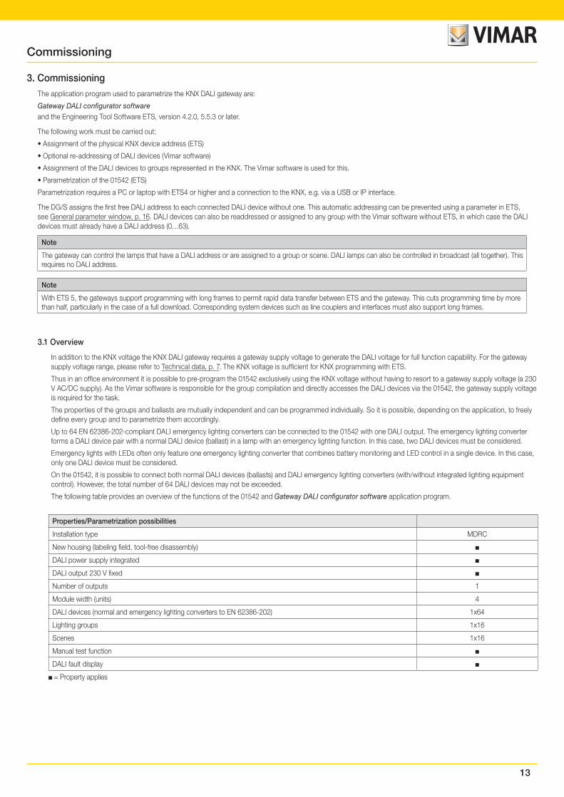
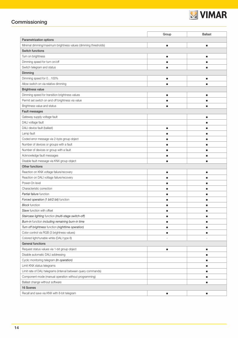
The following table provides an overview of the functions of the 01542 and Gateway DALI configurator software application program.
Properties/Parametrization possibilities
Installation type MDRC
New housing (labeling field, tool-free disassembly)
DALI power supply integrated
DALI output 230 V fixed
Number of outputs 1
Module width (units) 4
DALI devices (normal and emergency lighting converters to EN 62386-202) 1x64
Lighting groups 1x16
Scenes 1x16
Manual test function
DALI fault display
= Property applies
14
Group Ballast
Parametrization options
Minimal dimming/maximum brightness values (dimming thresholds)
Switch functions
Turn on brightness
Dimming speed for turn on/off
Switch telegram and status
Dimming
Dimming speed for 0…100%
Allow switch on via relative dimming
Brightness value
Dimming speed for transition brightness values
Permit set switch on and off brightness via value
Brightness value and status
Fault messages
Gateway supply voltage fault
DALI voltage fault
DALI device fault (ballast)
Lamp fault
Coded error message via 2-byte group object
Number of devices or groups with a fault
Number of devices or group with a fault
Acknowledge fault messages
Disable fault message via KNX group object
Other functions
Reaction on KNX voltage failure/recovery
Reaction on DALI voltage failure/recovery
Power-On level
Characteristic correction
Partial failure function
Forced operation (1 bit/2 bit) function
Block function
Slave function with offset
Staircase lighting function (multi-stage switch-off)
Burn-in function including remaining burn-in time
Turn off brightness function (nighttime operation)
Color control via RGB (3 brightness values)
Colored light/tunable white (DALI type 8) - -
General functions
Request status values via 1-bit group object
Disable automatic DALI addressing
Cyclic monitoring telegram (In operation)
Limit KNX status telegrams
Limit rate of DALI telegrams (interval between query commands)
Component mode (manual operation without programming)
Ballast change without software
16 Scenes
Recall and save via KNX with 8-bit telegram
Commissioning
15
Group Ballast
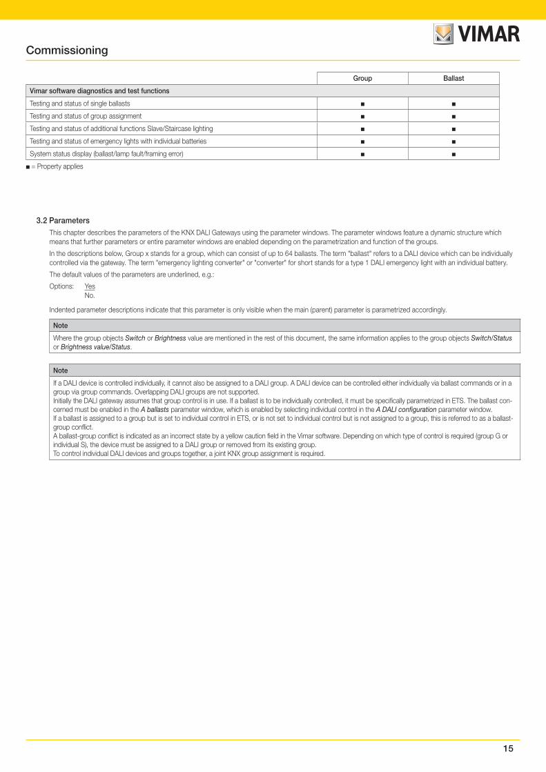
Vimar software diagnostics and test functions
Testing and status of single ballasts
Testing and status of group assignment
Testing and status of additional functions Slave/Staircase lighting
Testing and status of emergency lights with individual batteries
System status display (ballast/lamp fault/framing error)
= Property applies
3.2 ParametersThis chapter describes the parameters of the KNX DALI Gateways using the parameter windows. The parameter windows feature a dynamic structure which means that further parameters or entire parameter windows are enabled depending on the parametrization and function of the groups.
In the descriptions below, Group x stands for a group, which can consist of up to 64 ballasts. The term "ballast" refers to a DALI device which can be individually controlled via the gateway. The term "emergency lighting converter" or "converter" for short stands for a type 1 DALI emergency light with an individual battery.
The default values of the parameters are underlined, e.g.:
Options: Yes No.
Indented parameter descriptions indicate that this parameter is only visible when the main (parent) parameter is parametrized accordingly.
Note
Where the group objects Switch or Brightness value are mentioned in the rest of this document, the same information applies to the group objects Switch/Status or Brightness value/Status.
Note
If a DALI device is controlled individually, it cannot also be assigned to a DALI group. A DALI device can be controlled either individually via ballast commands or in a group via group commands. Overlapping DALI groups are not supported.Initially the DALI gateway assumes that group control is in use. If a ballast is to be individually controlled, it must be specifically parametrized in ETS. The ballast con-cerned must be enabled in the A ballasts parameter window, which is enabled by selecting individual control in the A DALI configuration parameter window.If a ballast is assigned to a group but is set to individual control in ETS, or is not set to individual control but is not assigned to a group, this is referred to as a ballast-group conflict.A ballast-group conflict is indicated as an incorrect state by a yellow caution field in the Vimar software. Depending on which type of control is required (group G or individual S), the device must be assigned to a DALI group or removed from its existing group.To control individual DALI devices and groups together, a joint KNX group assignment is required.
Commissioning
16
Commissioning
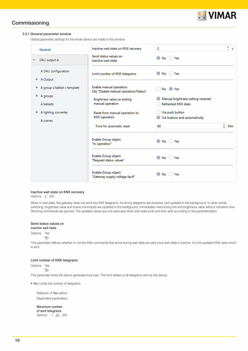
3.2.1 General parameter window
Global parameter settings for the whole device are made in this window.
Inactive wait state on KNX recoveryOptions: 2…255
When in wait state, the gateway does not send any KNX telegrams. Incoming telegrams are received, and updated in the background. In other words, switching, brightness value and scene commands are updated in the background, immediately memorizing the end brightness value without transition time. Dimming commands are ignored. The updated values are only executed when wait state ends and then sent according to the parametrization.
Send status values oninactive wait state
Options: Yes No
This parameter defines whether or not the KNX commands that arrive during wait state are sent once wait state is inactive. It is the updated KNX value which is sent.
Limit number of KNX telegrams
Options: Yes No
This parameter limits the device generated bus load. This limit relates to all telegrams sent by the device.
• Yes: Limits the number of telegrams.
Selection of Yes option:
Dependent parameters:
Maximum numberof sent telegramsOptions: 1…20…255
17
Commissioning
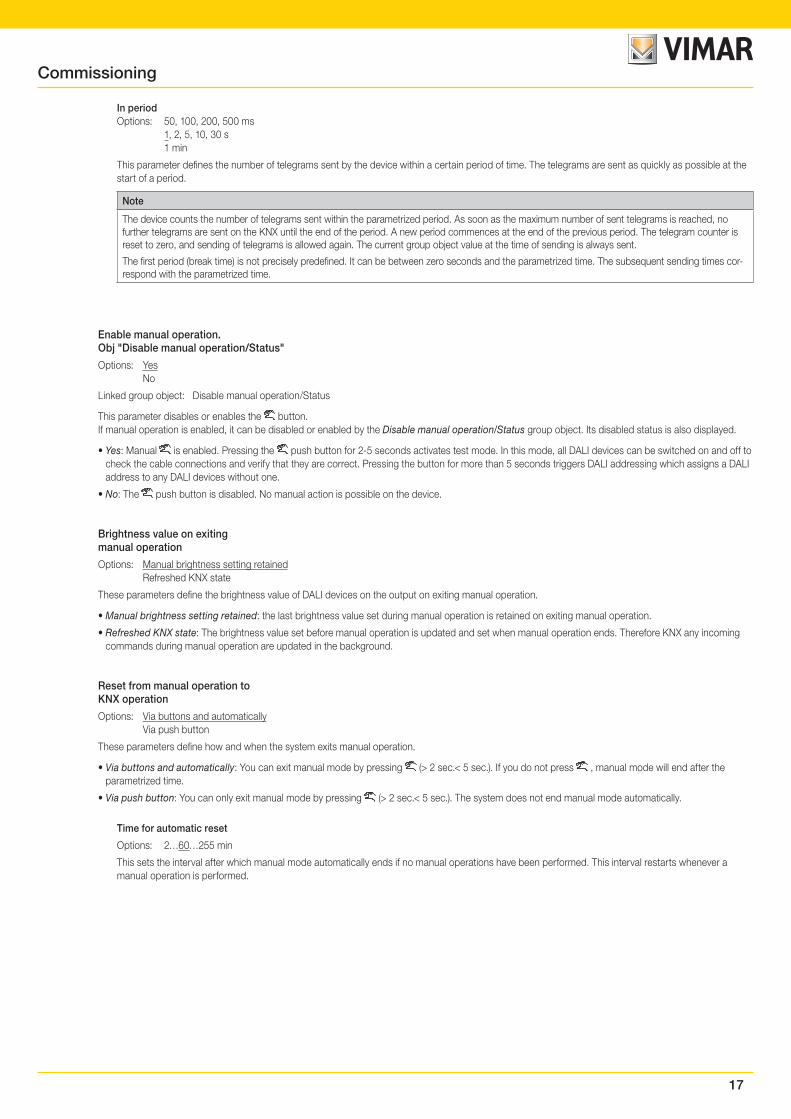
In periodOptions: 50, 100, 200, 500 ms 1, 2, 5, 10, 30 s 1 min
This parameter defines the number of telegrams sent by the device within a certain period of time. The telegrams are sent as quickly as possible at the start of a period.
Note
The device counts the number of telegrams sent within the parametrized period. As soon as the maximum number of sent telegrams is reached, no further telegrams are sent on the KNX until the end of the period. A new period commences at the end of the previous period. The telegram counter is reset to zero, and sending of telegrams is allowed again. The current group object value at the time of sending is always sent.
The first period (break time) is not precisely predefined. It can be between zero seconds and the parametrized time. The subsequent sending times cor-respond with the parametrized time.
Enable manual operation.Obj "Disable manual operation/Status"
Options: Yes No
Linked group object: Disable manual operation/Status
This parameter disables or enables the button.If manual operation is enabled, it can be disabled or enabled by the Disable manual operation/Status group object. Its disabled status is also displayed.
• Yes: Manual is enabled. Pressing the push button for 2-5 seconds activates test mode. In this mode, all DALI devices can be switched on and off to check the cable connections and verify that they are correct. Pressing the button for more than 5 seconds triggers DALI addressing which assigns a DALI address to any DALI devices without one.
• No: The push button is disabled. No manual action is possible on the device.
Brightness value on exitingmanual operation
Options: Manual brightness setting retained Refreshed KNX state
These parameters define the brightness value of DALI devices on the output on exiting manual operation.
• Manual brightness setting retained: the last brightness value set during manual operation is retained on exiting manual operation.
• Refreshed KNX state: The brightness value set before manual operation is updated and set when manual operation ends. Therefore KNX any incoming commands during manual operation are updated in the background.
Reset from manual operation toKNX operation
Options: Via buttons and automatically Via push button
These parameters define how and when the system exits manual operation.
• Via buttons and automatically: You can exit manual mode by pressing (> 2 sec.< 5 sec.). If you do not press , manual mode will end after the parametrized time.
• Via push button: You can only exit manual mode by pressing (> 2 sec.< 5 sec.). The system does not end manual mode automatically.
Time for automatic reset
Options: 2…60…255 min
This sets the interval after which manual mode automatically ends if no manual operations have been performed. This interval restarts whenever a manual operation is performed.
18
Commissioning
Enable Group object"In operation"
Options: Yes No
Linked group object: In operation
The In operation group object indicates the presence of the device on the KNX. This cyclic telegram can be monitored by an external device. If a telegram is not received, the device may be defective or the KNX cable to the transmitting device may be interrupted.
• Yes: The group object is enabled.
• No: The group object is not enabled.
Selection of Yes option:
Dependent parameters:
SendingOptions: Value 0 Value 1
The In operation group object is sent cyclically on the KNX.
Sending cycle timeOptions: 1…60…65.535 s
The time interval at which the In operation group object cyclically sends a telegram is set here.
Note
After a bus voltage recovery the group object sends its value after the set inactive wait state defined in the General parameter window has elapsed.
Enable Group object"Request status values"
Options: Yes No
Linked group object: Request status values
All status messages can be requested via this group object provided that they are set to After a change or on request or On request.
• Yes: The group object and function are enabled.
• No: The group object and function are not enabled.
Selection of Yes option:
Dependent parameters:
Request with object valueOptions: 0 1 0 or 1
• 0: Sending status messages is requested with the value 0.• 1: Sending status messages is requested with the value 1.• 0 or 1: Sending status messages is requested with the values 0 or 1.
19
Commissioning
Enable Group object"Gateway supply voltage fault"
Options: Yes No
Linked group object: Gateway supply voltage fault
• Yes: The Gateway supply voltage fault group object is enabled. As soon as the device supply voltage is interrupted, the Gateway supply voltage fault group object sends a telegram with the value 1 on the KNX. The time at which a telegram is sent can be adjusted using the parameter below.
• No: The gateway supply voltage failure is not signaled to the KNX.
Selection of Yes option:
Dependent parameters:
Send object valueOptions: On change On request After a change or on request
• On change: The status is sent when a change occurs.• On request: The status is sent when a request occurs.• After a change or on request: The status is sent when either a change or request occurs.
Enable acknowledgement via object"Acknowledge gateway supplyvoltage fault"
Options: Yes No
Linked group object: Acknowledge gateway supply voltage fault
• Yes: The Acknowledge Gateway supply voltage fault group object is enabled. The fault is only reset by an acknowledgment (a telegram with the value 1) via this group object, or via the Vimar software.
• No: The Gateway supply voltage fault group object requires no acknowledgement. The group object value is updated when a change occurs.
3.2.2 DALI output X parameter window
General parameter settings for output X are made in this window.
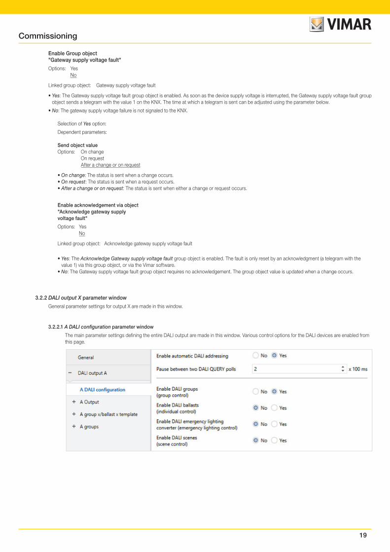
3.2.2.1 A DALI configuration parameter window
The main parameter settings defining the entire DALI output are made in this window. Various control options for the DALI devices are enabled from this page.
20
Commissioning
Enable automatic DALI addressing
Options: Yes No
This parameter switches off the DG/S automatic DALI addressing process.
• Yes: If the 01542 locates a DALI device without a DALI address, the 01542 automatically allocates it the first free DALI address.
Advantage
DALI addressing without gaps makes it possible to replace a defective DALI device without additional addressing or commissioning. All that is required is to connect a new DALI device without a DALI address.
The 01542 addresses the new device with the first free DALI address of the removed failed device, and transfers its properties to the new device. If this DALI device does not yet have a group address (it is new from the factory), it will also receive the group assignment. If another group assignment exists in the DALI device, a conflict will be indicated in the Vimar software. This can be remedied with the Vimar software by applying the 01542 or ballast information.
If the 01542 detects several DALI devices with the same DALI address, it deletes these addresses and automatically assigns them the first free DALI addresses in the address range.
• No: The 01542 does not assign DALI addresses, either in normal mode or on gateway supply voltage recovery. If a DALI device without an address has been installed, the 01542 can only control it using a broadcast telegram (manual operation). A DALI address is not necessary for this purpose. If a DALI device with an existing address has been installed, the 01542 will not change it.
Pause between two DALI QUERY polls
Options: 0…2…255 x 100 ms
This parameter sets the interval between DALI QUERY polls. The gateway automatically and cyclically sends a brightness value query on the DALI to each possible DALI device (Actual Level DALI query).
A 0 setting runs the QUERY poll as quickly as possible. The interval between QUERY telegrams is around 30...40 ms.
The gateway uses this poll to establish whether a DALI device with a DALI address is present. If it does not receive a response from the monitored DALI device, the gateway interprets this as a device fault. If it does receive a response, it polls other properties of the DALI device (e.g. lamp faults and DALI device type).
This time setting has a direct impact on the DALI telegram bus load. A long interval reduces the load significantly. However, the disadvantage of this is that a fault on a DALI device may not be detected straight away. Likewise, it takes longer to detect a new or recovered device.
Other than this, the setting has no influence on DALI telegram rate. DALI commands (e.g. switching, dimming and brightness value settings etc.) and status signals (e.g. brightness values, emergency lighting information etc.) or functions in progress (e.g. staircase lighting, forced operation etc.) are neither influenced nor delayed.
Note
We recommend that you keep the default settings. The only time that it makes sense to increase the interval between DALI QUERY polls is for exam-ple if an emergency lighting switch is installed in the DALI line, so as to allow more time for switching.
Enable DALI groups(group control)
Options: Yes No
Linked group object: Various "Output X group Y" group objects
• Yes: DALI group control is supported on the DALI output. Corresponding parameter windows and group objects are enabled. DALI groups are compiled with DALI devices via the Vimar software. There are 16 DALI groups available per DALI output. Individual DALI groups can be selected in the Group x parameter window..
DALI devices which are assigned to a group cannot be used for individual control. This configuration is shown in the Vimar software and needs to be removed.
• No: DALI group control is not supported on the DALI output. No corresponding parameter windows and group objects are enabled, so the ETS parameter structure here is very concise.
21
Commissioning
Enable DALI ballasts(individual control)
Options: Yes No
Linked group object: Various "Output X ballast Y" group objects
• Yes: Individual device control is supported on the DALI output. Corresponding parameter windows and group objects are enabled. DALI address-ing can be flexibly handled in the Vimar software. Up to 64 DALI devices can be connected to each output. Individual DALI devices can be hidden in the A ballasts parameter window to provide a clear, compact parameter structure.
DALI devices which are assigned to a group cannot be used for individual control. This configuration is shown in the Vimar software (yellow field) and needs to be removed.
• No: Individual device control is supported on the DALI output. No corresponding parameter windows and group objects are enabled, so the ETS parameter structure here is very concise.
Note
If a DALI device is controlled individually, it cannot also be assigned to a DALI group. A DALI device can be controlled either individually via ballast commands or in a group via group commands. Overlapping DALI groups are not supported.
Initially the DALI gateway assumes that group control is in use. If a ballast is to be individually controlled, it must be specifically parametrized in ETS. The ballast concerned must be enabled in the A ballasts parameter window, which is enabled by selecting individual control in the A DALI configura-tion parameter window.
If a ballast is assigned to a group but is set to individual control in ETS, or is not set to individual control but is not assigned to a group, this is referred to as a ballast-group conflict.
A ballast-group conflict is indicated as an incorrect state by a yellow caution field in the Vimar software. Depending on which type of control is required (group G or individual S), the device must be assigned to a DALI group or removed from its existing group.
To control individual DALI devices and groups together, a joint KNX group assignment is required.
Enable DALI emergency lightingconverter (emergency lighting control)
Options: Yes No
Linked group object: Various "Output X ballast Y" group objects
• Yes: The DALI output supports control of DALI emergency lighting converters (type 1 DALI devices, emergency lights with individual batteries to DIN EN 62386-202). Corresponding parameter windows and group objects are enabled. DALI addressing for the emergency lighting converters can be flexibly handled in the Vimar software. Up to 64 DALI emergency lighting converters can be connected to each output. Individual DALI emergency lighting converters can be hidden in the A lighting converter parameter window to provide a clear, compact parameter structure.
DALI emergency lighting converters can also be assigned to a DALI group for a clearer overview. Again, in such cases the converters can only be controlled individually. They have no group function.
• No: Emergency lighting converter control is not supported on the DALI output. No corresponding parameter windows and group objects are enabled, so the ETS parameter structure here is very concise.
Enable DALI scenes(scene control)
Options: Yes No
Linked group object: Scenes 1…16
• Yes: The DALI output supports control for up to 16 DALI scenes. The corresponding parameter window A scenes and the Scenes 1…16 group object are enabled.
There are 16 DALI light scenes available on each DALI output; these can be assigned to any of the 16 KNX scenes. So for example, DALI scene 8, which is parametrized in the DALI gateway, can be assigned to KNX scene 35 and recalled or saved using the KNX scene commands for scene 35.
• No: The DALI output does not support the Scenes function. No corresponding parameter windows and group objects are enabled, so the ETS parameter structure here is very concise.
Note
Scene numbers 1 to 16 shown in the gateway are mapped to scenes 0 to 15 on the DALI.
22
Commissioning
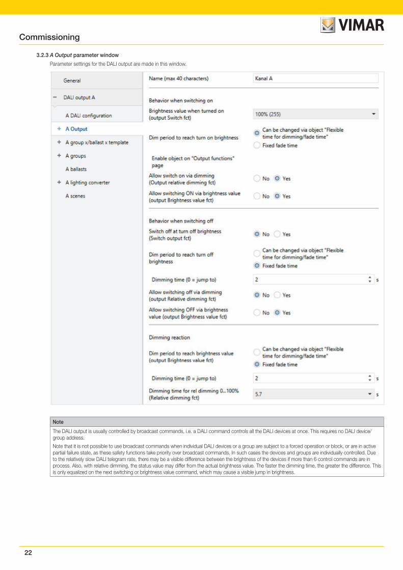
3.2.3 A Output parameter window
Parameter settings for the DALI output are made in this window.
Note
The DALI output is usually controlled by broadcast commands, i.e. a DALI command controls all the DALI devices at once. This requires no DALI device/group address.
Note that it is not possible to use broadcast commands when individual DALI devices or a group are subject to a forced operation or block, or are in active partial failure state, as these safety functions take priority over broadcast commands. In such cases the devices and groups are individually controlled. Due to the relatively slow DALI telegram rate, there may be a visible difference between the brightness of the devices if more than 6 control commands are in process. Also, with relative dimming, the status value may differ from the actual brightness value. The faster the dimming time, the greater the difference. This is only equalized on the next switching or brightness value command, which may cause a visible jump in brightness.
23
Commissioning
Name (max 40 characters)
Options: Channel A
The output can be assigned a name with a maximum of 40 characters.
The name is stored in the ETS database, and also stored in the gateway by downloading the application.
Brightness value when turned onoutput Switch fct)
Options: Previous value 100% (255) 99% (252) … 1% (3)
This parameter defines the brightness value used when the DALI output switches on after receiving an ON telegram.
The dimming thresholds set for the group or ballast apply to the individual ballasts and groups.
• Previous value: The output switches on at the brightness value it was switched off at by the Switch group object. The brightness value of each ballast and group are saved when they are switched off, and restored when they are switched back on.
If a ballast or group is OFF when switched off, the previous brightness value is saved as 0% (OFF) and is switched back on in the same state. This means that the group or ballast will be switched off unless it has a brightness value other than 0 when switched back on.
Note
The previous brightness value is saved with every OFF telegram on the output unless the output is already switched off. If this is the case, the OFF state is not saved as the last brightness value on receipt of another OFF telegram. The output is not switched off if every group or ballast is already switched off.
If a new OFF telegram is received during dimming down, the current brightness value is saved as the last brightness value.
In the event of a KNX voltage failure, download or restart, the previous brightness value is lost and is set to the parametrized turn on brightness value when the gateway supply voltage is restored.
Separate previous brightness values are saved for the ballast/group and the output.This means that if the output is dimmed or switched on or off by a central telegram, the previous brightness value for the ballast/group remains unchanged.
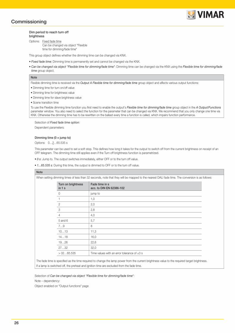
Dim period to reach turn on brightness
Options: Fixed fade time Can be changed via object "Flexible time for dimming/fade time"
This group object defines whether the dimming time can be changed via KNX.
• Fixed fade time: Dimming time is permanently set and cannot be changed via the KNX.
• Can be changed via object "Flexible time for dimming/fade time": Dimming time can be changed via the KNX using the Flexible time for dimming/fade time group object.
Note
Flexible dimming time is received via the Output A Flexible time for dimming/fade time group object and affects various output functions:
• Dimming time for turn on/off value
• Dimming time for brightness value
• Dimming time for slave brightness value
• Scene transition time
To use the Flexible dimming time function you first need to enable the output's Flexible time for dimming/fade time group object in the A Output/Functions parameter window. You also need to select the function for the parameter that can be changed via KNX. We recommend that you only change one time via KNX. Otherwise the dimming time has to be rewritten on the ballast every time a function is called, which impairs function performance.
Selection of Fixed fade time option:
Dependent parameters:
Dimming time (0 = jump to)
Options: 0…2…65.535 s
This parameter can be used to set a soft start by defining how long the output takes to dim up from 0% brightness to the turn on brightness when it receives an ON telegram. This time period refers to ON telegrams only (1 bit).
• 0 s: jump to: The output switches ON immediately (DALI ON command).
• 1…65.535 s: During this time, the output is dimmed from 0% brightness to the turn on brightness.
24
Commissioning
Note
When setting dimming times of less than 32 seconds, note that they will be mapped to the nearest DALI fade time. The conversion is as follows:
Turn on brightnessin 1 s
Fade time in sacc. to DIN EN 62386-102
0 jump to
1 1,0
2 2,0
3 2,8
4 4,0
5 and 6 5,7
7…9 8
10…13 11,3
14…18 16,0
19…26 22,6
27…32 32,0
> 32…65.535 Time values with an error tolerance of ±3 s
The fade time is specified as the time required to change the lamp power from the current brightness value to the required target brightness.
If a lamp is switched off, the preheat and ignition time are excluded from the fade time.
Selection of Can be changed via object "Flexible time for dimming/fade time":
Note – dependency:
Object enabled on "Output functions" page
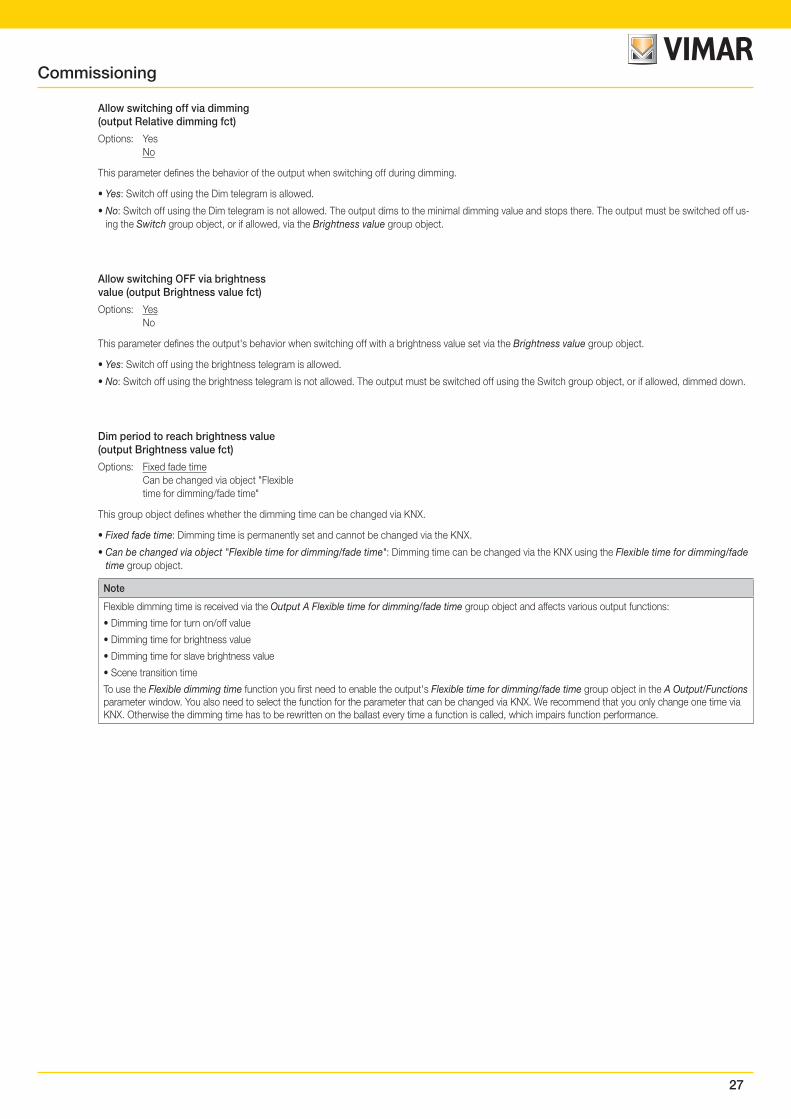
Allow switch on via dimming(Output relative dimming fct)
Options: Yes No
This parameter defines the output's behavior when switching on with dimming via the Relative dimming group object.
• Yes: Switching on using the Dim telegram is allowed.
• No: Switching on using the Dim telegram is not allowed. The output must be switched on in order to be dimmed.
Allow switching ON via brightness value(output Brightness value fct)
Options: Yes No
This parameter defines the output's behavior when switching on with a brightness value set via the Brightness value group object.
• Yes: Switching on using the Brightness telegram is allowed.
• No: Switching on using the brightness telegram is not allowed. The output must be switched on in order for a brightness value to be set.
25
Commissioning
Switch off at turn off brightness(Switch output fct)
Options: Yes No
This parameter defines whether receipt of an OFF telegram turns off the lighting immediately or whether it must first reach a turn off brightness.
• Yes: A parametrizable brightness value, the turn off brightness, triggers switch-off, while a value of 0 does not.
• No: The lighting switches off at the parametrized dimming time (OFF, brightness value 0%).
Note
The Turn off brightness function can be used e.g. to prevent the lighting from switching off completely at night in retirement homes or hospitals, so that there is always a basic brightness – the turn off brightness.
Selection of Yes option:
Dependent parameters:
Turn off brightness
Options: 100% (255) 99% (252) … 30% (77) … 2% (5) 1% (3)
This parameter defines the brightness value for the Turn off brightness function, i.e. the brightness at which the output switches off when it receives an OFF telegram.
Values set outside the thresholds (maximum brightness/minimal dimming value) are automatically adjusted to the maximum or minimum.
Group object"Activate fct Turn off brightness"(enable in "Output functions")
Options: Yes No
Turn off brightness can be activated/deactivated via the KNX using the Activate fct Turn off brightness group object. This means a timer can be used, for example, to set the lighting to a parametrizable turn off brightness at night instead of switching it off.
• Yes: The output evaluates the Activate fct Turn off brightness group object. If the gateway receives a telegram via this group object on the output, the system reacts as follows:
1: The turn off brightness is set to the parametrized brightness value. The Turn off brightness function is activated. An OFF command will then apply this brightness value instead of OFF, 0%.
0: The brightness value is set to 0. The Turn off brightness function is not activated and an OFF command switches the system off via the Switch group object, applying a brightness value of OFF, 0%.
• No: The output does not evaluate the Activate fct Turn off brightness group object. The system always switches off at the parametrized turn off bright-ness.
Note
The Turn off brightness function can be applied to the whole DALI output, all ballasts and all groups. It must first be enabled in the A Output functions parameter window along with the Activate fct Turn off brightness group object.
To define whether the output, a ballast or a group reacts to the Turn off brightness function on the output, make the settings in the relevant parameter window: A Output, Ballast x or Group x.
26
Commissioning
Dim period to reach turn offbrightness
Options: Fixed fade time Can be changed via object "Flexible time for dimming/fade time"
This group object defines whether the dimming time can be changed via KNX.
• Fixed fade time: Dimming time is permanently set and cannot be changed via the KNX.
• Can be changed via object "Flexible time for dimming/fade time": Dimming time can be changed via the KNX using the Flexible time for dimming/fade time group object.
Note
Flexible dimming time is received via the Output A Flexible time for dimming/fade time group object and affects various output functions:
• Dimming time for turn on/off value
• Dimming time for brightness value
• Dimming time for slave brightness value
• Scene transition time
To use the Flexible dimming time function you first need to enable the output's Flexible time for dimming/fade time group object in the A Output/Functions parameter window. You also need to select the function for the parameter that can be changed via KNX. We recommend that you only change one time via KNX. Otherwise the dimming time has to be rewritten on the ballast every time a function is called, which impairs function performance.
Selection of Fixed fade time option:
Dependent parameters:
Dimming time (0 = jump to)
Options: 0…2…65.535 s
This parameter can be used to set a soft stop. This defines how long it takes for the output to switch off from the current brightness on receipt of an OFF telegram. The dimming time still applies even if the Turn off brightness function is parametrized.
• 0 s: Jump to. The output switches immediately, either OFF or to the turn off value.
• 1…65.535 s: During this time, the output is dimmed to OFF or to the turn off value.
Note
When setting dimming times of less than 32 seconds, note that they will be mapped to the nearest DALI fade time. The conversion is as follows:
Turn on brightnessin 1 s
Fade time in sacc. to DIN EN 62386-102
0 jump to
1 1,0
2 2,0
3 2,8
4 4,0
5 and 6 5,7
7…9 8
10…13 11,3
14…18 16,0
19…26 22,6
27…32 32,0
> 32…65.535 Time values with an error tolerance of ±3 s
The fade time is specified as the time required to change the lamp power from the current brightness value to the required target brightness.
If a lamp is switched off, the preheat and ignition time are excluded from the fade time.
Selection of Can be changed via object "Flexible time for dimming/fade time":
Note – dependency:
Object enabled on "Output functions" page
27
Commissioning
Allow switching off via dimming(output Relative dimming fct)
Options: Yes No
This parameter defines the behavior of the output when switching off during dimming.
• Yes: Switch off using the Dim telegram is allowed.
• No: Switch off using the Dim telegram is not allowed. The output dims to the minimal dimming value and stops there. The output must be switched off us-ing the Switch group object, or if allowed, via the Brightness value group object.
Allow switching OFF via brightnessvalue (output Brightness value fct)
Options: Yes No
This parameter defines the output's behavior when switching off with a brightness value set via the Brightness value group object.
• Yes: Switch off using the brightness telegram is allowed.
• No: Switch off using the brightness telegram is not allowed. The output must be switched off using the Switch group object, or if allowed, dimmed down.
Dim period to reach brightness value(output Brightness value fct)
Options: Fixed fade time Can be changed via object "Flexible time for dimming/fade time"
This group object defines whether the dimming time can be changed via KNX.
• Fixed fade time: Dimming time is permanently set and cannot be changed via the KNX.
• Can be changed via object "Flexible time for dimming/fade time": Dimming time can be changed via the KNX using the Flexible time for dimming/fade time group object.
Note
Flexible dimming time is received via the Output A Flexible time for dimming/fade time group object and affects various output functions:
• Dimming time for turn on/off value
• Dimming time for brightness value
• Dimming time for slave brightness value
• Scene transition time
To use the Flexible dimming time function you first need to enable the output's Flexible time for dimming/fade time group object in the A Output/Functions parameter window. You also need to select the function for the parameter that can be changed via KNX. We recommend that you only change one time via KNX. Otherwise the dimming time has to be rewritten on the ballast every time a function is called, which impairs function performance.
28
Commissioning
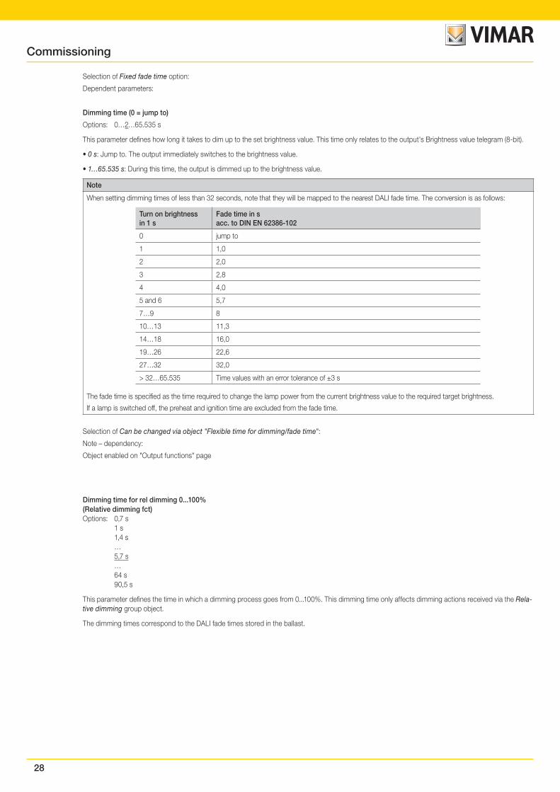
Selection of Fixed fade time option:
Dependent parameters:
Dimming time (0 = jump to)
Options: 0…2…65.535 s
This parameter defines how long it takes to dim up to the set brightness value. This time only relates to the output's Brightness value telegram (8-bit).
• 0 s: Jump to. The output immediately switches to the brightness value.
• 1…65.535 s: During this time, the output is dimmed up to the brightness value.
Note
When setting dimming times of less than 32 seconds, note that they will be mapped to the nearest DALI fade time. The conversion is as follows:
Turn on brightnessin 1 s
Fade time in sacc. to DIN EN 62386-102
0 jump to
1 1,0
2 2,0
3 2,8
4 4,0
5 and 6 5,7
7…9 8
10…13 11,3
14…18 16,0
19…26 22,6
27…32 32,0
> 32…65.535 Time values with an error tolerance of ±3 s
The fade time is specified as the time required to change the lamp power from the current brightness value to the required target brightness.
If a lamp is switched off, the preheat and ignition time are excluded from the fade time.
Selection of Can be changed via object "Flexible time for dimming/fade time":
Note – dependency:
Object enabled on "Output functions" page
Dimming time for rel dimming 0...100%(Relative dimming fct)Options: 0,7 s 1 s 1,4 s … 5,7 s … 64 s 90,5 s
This parameter defines the time in which a dimming process goes from 0...100%. This dimming time only affects dimming actions received via the Rela-tive dimming group object.
The dimming times correspond to the DALI fade times stored in the ballast.
29
Commissioning
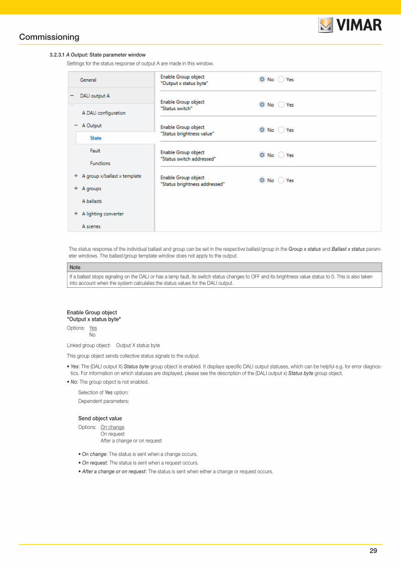
3.2.3.1 A Output: State parameter window
Settings for the status response of output A are made in this window.
The status response of the individual ballast and group can be set in the respective ballast/group in the Group x status and Ballast x status param-eter windows. The ballast/group template window does not apply to the output.
Note
If a ballast stops signaling on the DALI or has a lamp fault, its switch status changes to OFF and its brightness value status to 0. This is also taken into account when the system calculates the status values for the DALI output.
Enable Group object"Output x status byte"
Options: Yes No
Linked group object: Output X status byte
This group object sends collective status signals to the output.
• Yes: The (DALI output X) Status byte group object is enabled. It displays specific DALI output statuses, which can be helpful e.g. for error diagnos-tics. For information on which statuses are displayed, please see the description of the (DALI output x) Status byte group object.
• No: The group object is not enabled.
Selection of Yes option:
Dependent parameters:
Send object value
Options: On change On request After a change or on request
• On change: The status is sent when a change occurs.
• On request: The status is sent when a request occurs.
• After a change or on request: The status is sent when either a change or request occurs.
30
Enable Group object"Status switch"
Options: Yes No
Linked group object: Status switch
• Yes: The (DALI output X) Status switch group object is enabled. It sends a 1-bit telegram on the KNX, signaling the current switch status.
• No: The status of the switch state is not actively sent on the KNX.
Selection of Yes option:
Dependent parameters:
Send object value
Options: On change On request After a change or on request
• On change: The status is sent when a change occurs.
• On request: The status is sent when a request occurs.
• After a change or on request: The status is sent when either a change or request occurs.
Value for different switchingstates at DALI output
Options: ON OFF
This parameter defines the status to be sent if DALI devices with different states are present on the output.
• ON: The switch status is sent as ON (telegram value 1) if at least one DALI device is switched on.
• OFF: The switch status is only sent as ON (telegram value 1) if all DALI devices are switched on.
Enable Group object"Status brightness value"
Options: Yes No
Linked group object: Status brightness value
The parameter defines how the current status of the DALI output brightness value is sent on the KNX.
• Yes: The (DALI output X) Status brightness value group object is enabled for the brightness value.
• No: The brightness value is not actively sent on the KNX.
Selection of Yes option:
Dependent parameters:
Send object value
Options: On change On request After a change or on request
• On change: The status is sent when a change occurs.
• On request: The status is sent when a request occurs.
• After a change or on request: The status is sent when either a change or request occurs.
Commissioning
31
Send interim values on transfers(e.g. Dim up, scene transfer)
Options: No Yes
This parameter defines whether the brightness value status is only sent at the end of the brightness value transition or whether interim values are sent.
• No: The brightness status is sent on the KNX once the final brightness value has been reached.
• Yes: The brightness value status is also sent during a brightness value transition.
Selection of Yes option:
Dependent parameters:
Send interval
Options: 0…2…65.535 s
This parameter defines the send interval for the brightness value status during a brightness value transition (e.g. dimming up, scene transi-tion).
Value for different brightnessstates at DALI output
Options: Average brightness of all lamps in the output Highest brightness of all lamps in the output Lowest brightness of all lamps in the output
This parameter defines the status to be sent if DALI devices with different states are present on the output.
• Average brightness of all lamps in the output: The average brightness of all the DALI devices is sent on the KNX as the status of the DALI output.
• Highest brightness of all lamps in the output: The highest brightness value of the DALI devices is sent on the KNX as the status of the DALI output.
• Lowest brightness of all lamps on the output: The lowest brightness value of the DALI devices is sent on the KNX as the status of the DALI output.
Enable Group object"Status switch addressed"
Options: Yes No
Linked group object: Status switch addressed
• Yes: The coded group object Status switch addressed is enabled. This coded 2-byte group object (address plus status) sends the switching state of a ballast or group on the KNX.
• No: The addressed status of the switch state of a ballast or group is not actively sent on the KNX.
The object value is only sent on request with the ballast or group number.
Enable Group object"Status brightness addressed"
Options: Yes No
Linked group object: Status brightness addressed
• Yes: The coded group object Status brightness addressed is enabled. This coded 2-byte group object (address plus status) sends the switching state of a ballast or group on the KNX.
• No: The addressed status of the brightness value of a ballast or group is not actively sent on the KNX.
The object value is only sent on request with the ballast or group number.
Commissioning
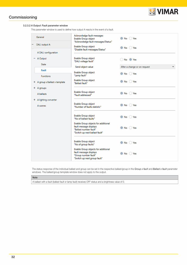
32
3.2.3.2 A Output: Fault parameter window
This parameter window is used to define how output A reacts in the event of a fault.
The status response of the individual ballast and group can be set in the respective ballast/group in the Group x fault and Ballast x fault parameter windows. The ballast/group template window does not apply to the output.
Note
A ballast with a fault (ballast fault or lamp fault) receives OFF status and a brightness value of 0.
Commissioning
33
Acknowledge fault messagesEnable Group object"Acknowledge fault messages/Status"
Options: Yes No
Linked group object: Acknowledge fault messages/Status
This parameter enables the Acknowledge faults function and its required group object.
• Yes: The Acknowledge faults function and its required group object are enabled.
• No: The Acknowledge faults function and group object are not enabled.
Fault messages are usually automatically reset once the fault has been corrected. With the Acknowledge faults function, the message is only cleared by acknowledgment. Only then is a telegram with the value 0 sent via the group object for the corresponding fault type. This function can be very helpful when detecting sporadic faults or events which take place during unmanned monitoring periods.
Note
The Acknowledge faults function relates to the whole DALI output and fault messages for ballasts and groups, with the exception of the gateway supply voltage fault, which can be acknowledged separately.
Enable Group object"Disable fault messages/Status"
Options: Yes No
Linked group object: Disable fault messages/Status
This parameter enables the Disable fault messages/Status group object. At the same time, it makes the Disable fault messages function available. When messages are disabled, the faults are evaluated but not sent on the KNX bus. Nor are the values of the group objects updated.
The Disable fault messages/Status group object not only activates and deactivates the function but also sends or reads its status.
Disabling fault messages minimizes system latency by reducing the KNX load.
When fault messages are enabled, all faults are sent in accordance with their parametrization. If a fault still exists after fault messages are enabled, this fault is recorded and the information is sent on the KNX in accordance with the parametrization.
• Yes: The Disable fault messages function and group object are enabled.
• No: The Disable fault messages function and group object are not enabled.
Enable Group object"DALI voltage fault"
Options: Yes No
Linked group object: DALI voltage fault
This group object indicates a DALI voltage fault. The fault may be a surge, overload or short circuit. For more detailed information please see the Output X Status byte group object.
• Yes: The group object is enabled.
• No: The group object is not enabled.
Selection of Yes option:
Dependent parameters:
Send object value
Options: On change On request After a change or on request
• On change: The status is sent when a change occurs.
• On request: The status is sent when a request occurs.
• After a change or on request: The status is sent when either a change or request occurs.
Commissioning
34
Enable Group object"Lamp fault"
Options: Yes No
Linked group object: Lamp fault
This group object indicates a fault on a lamp for the DALI output.
• Yes: The group object is enabled.
• No: The group object is not enabled.
Note
A ballast fault takes priority over a lamp fault. The ballast fault masks and hides the lamp fault.
Selection of Yes option:
Dependent parameters:
Send object value
Options: On change On request After a change or on request
• On change: The status is sent when a change occurs.
• On request: The status is sent when a request occurs.
• After a change or on request: The status is sent when either a change or request occurs.
Enable Group object"Ballast fault"
Options: Yes No
Linked group object: Ballast fault
This group object indicates a fault on a ballast for the DALI output.
• Yes: The group object is enabled.
• No: The group object is not enabled.
Note
A ballast fault takes priority over a lamp fault. The ballast fault masks and hides the lamp fault.
Note
To detect a ballast fault correctly the gateway needs to monitor all connected DALI devices. Monitoring can be triggered either via the Monitor DALI addresses group object or via the commissioning tool. There is no automatic detection, e.g. after a KNX bus voltage recovery or gateway supply volt-age recovery.
Activation should be carried out straight after commissioning or when adding or removing DALI devices.
The DALI devices are continually monitored regardless of whether the lamp is active or not. The DALI devices must be properly installed and have a supply voltage.
Any existing lamp fault is reset, as it is no longer possible to state information about the group or ballast.
At what point a ballast fault is detected depends on when the gateway polls the DALI devices. This interval can be set via the Pause between two DALI QUERY polls parameter in the Output A – A DALI configuration parameter window.
Selection of Yes option:
Dependent parameters:
Send object value
Options: On change On request After a change or on request
• On change: The status is sent when a change occurs.
• On request: The status is sent when a request occurs.
• After a change or on request: The status is sent when either a change or request occurs.
Commissioning
35
Enable Group object"Fault addressed"
Options: Yes No
Linked group object: Fault addressed
Depending on parametrization, this group object sends the status of a group or ballast fault in the 2-byte coded group object Fault addressed. However, the parameters can also be queried.
• Yes: The group object is enabled. As soon as there is a ballast, lamp or other fault on a DALI device on the output, this is indicated by a value of 1 in the corresponding bit.
• No: The group object is not enabled.
Selection of Yes option:
Dependent parameters:
Send object value
Options: On change On request After a change or on request
• On change: The status is sent when a change occurs.
• On request: The status is sent when a request occurs.
• After a change or on request: The status is sent when either a change or request occurs.
Enable Group object"Number of faults statistic"
Options: Yes No
Linked group object: Number of faults statistic
This group object consists of 4 bytes. The individual bytes contain the number of faults for the DALI output as a whole.
• Yes: The group object is enabled. This coded 4-byte group object indicates the number of ballast, lamp and emergency lighting converter faults as well as the error state.
• No: The group object is not enabled.
Selection of Yes option:
Dependent parameters:
Send object value
Options: On change On request After a change or on request
• On change: The status is sent when a change occurs.
• On request: The status is sent when a request occurs.
• After a change or on request: The status is sent when either a change or request occurs.
Commissioning
36
Enable Group object"No of ballast faults"
Options: Yes No
Linked group object: Number of ballast faults
• Yes: The group object is enabled. This group object indicates the number of faulty DALI devices on the output. In this case a fault means lamp or a ballast fault.
• No: The group object is not enabled.
Selection of Yes option:
Dependent parameters:
Send object value
Options: On change On request After a change or on request
• On change: The status is sent when a change occurs.
• On request: The status is sent when a request occurs.
• After a change or on request: The status is sent when either a change or request occurs.
Enable Group objects for additionalfault message displays"Ballast number fault""Switch up next ballast fault"
Options: Yes No
Linked group object: Ballast number fault Switch up next ballast fault
This parameter enables two group objects. The first indicates the number of the faulty ballast. If there are several faults, the address of the next device with a fault can be displayed via the Switch up next ballast fault group object. Here, a fault means a lamp or ballast fault.
• Yes: The expanded ballast fault message display is enabled.
• No: The additional group objects for number-dependent device fault display are not enabled.
Enable Group object"No of group faults"
Options: Yes No
Linked group object: Number of group faults
• Yes: The group object is enabled. This group object indicates the number of faulty groups on the output. Here, a fault means a lamp or ballast fault.
• No: The group object is not enabled.
Selection of Yes option:
Dependent parameters:
Send object value
Options: On change On request After a change or on request
• On change: The status is sent when a change occurs.
• On request: The status is sent when a request occurs.
• After a change or on request: The status is sent when either a change or request occurs.
Commissioning
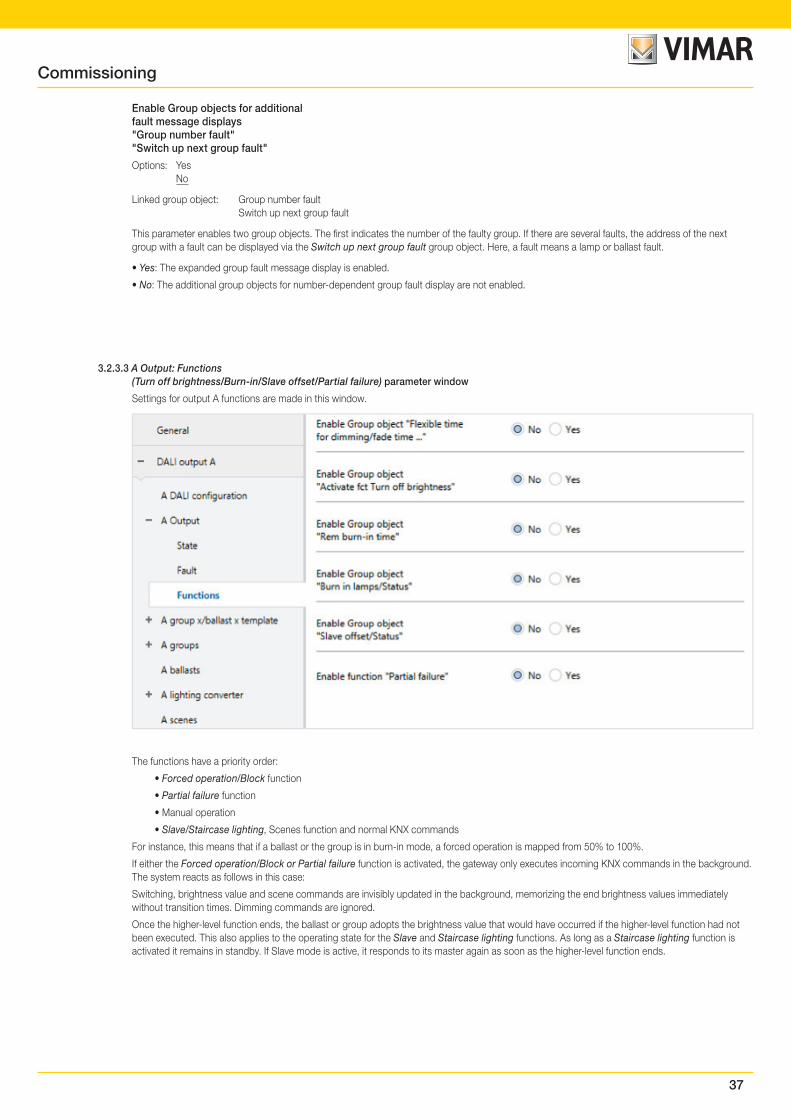
37
Enable Group objects for additionalfault message displays"Group number fault""Switch up next group fault"
Options: Yes No
Linked group object: Group number fault Switch up next group fault
This parameter enables two group objects. The first indicates the number of the faulty group. If there are several faults, the address of the next group with a fault can be displayed via the Switch up next group fault group object. Here, a fault means a lamp or ballast fault.
• Yes: The expanded group fault message display is enabled.
• No: The additional group objects for number-dependent group fault display are not enabled.
3.2.3.3 A Output: Functions(Turn off brightness/Burn-in/Slave offset/Partial failure) parameter window
Settings for output A functions are made in this window.
The functions have a priority order:
• Forced operation/Block function
• Partial failure function
• Manual operation
• Slave/Staircase lighting, Scenes function and normal KNX commands
For instance, this means that if a ballast or the group is in burn-in mode, a forced operation is mapped from 50% to 100%.
If either the Forced operation/Block or Partial failure function is activated, the gateway only executes incoming KNX commands in the background. The system reacts as follows in this case:
Switching, brightness value and scene commands are invisibly updated in the background, memorizing the end brightness values immediately without transition times. Dimming commands are ignored.
Once the higher-level function ends, the ballast or group adopts the brightness value that would have occurred if the higher-level function had not been executed. This also applies to the operating state for the Slave and Staircase lighting functions. As long as a Staircase lighting function is activated it remains in standby. If Slave mode is active, it responds to its master again as soon as the higher-level function ends.
Commissioning
38
Enable Group object "Flexible timefor dimming/fade time ..."
Options: Yes No
Linked group object: Flexible time for dimming/fade time ...
This group object changes various dimming times via the KNX. It can affect various ballasts, groups and the output. Whether the ballast, group or output evaluates this group object is defined in the corresponding ballast, group or output. This group object can influence the following functions.
• Dimming time for turn on/off value
• Dimming time for brightness value
• Dimming time for slave brightness value
• Scene transition time
Note
To use the Flexible dimming time function you first need to enable the output's Flexible time for dimming/fade time group object in the A Output parameter window. You also need to select the function for the parameter that can be changed via KNX. We recommend that you only change one time via KNX. Otherwise the dimming time has to be rewritten on the ballast every time a function is called, which impairs function performance.
• Yes: The Flexible time for dimming/fade time ... group object is enabled. It can be used to change the dimming time for various functions.
• No: The group object is not enabled.
Selection of Yes option:
Dependent parameters:
Object format of flexible time fordimming/fade time
Options: DALI format (1...15) KNX format time 100 ms KNX format time 1 s
Linked group object: Dimming/fade time (DALI format (0…15)) Dimming/fade time (time 100 ms)) Dimming/fade time (time 1 s)
• DALI format (1...15): The values received via the group object are interpreted by the gateway as a discreet numeric value, which is directly converted to the DALI value for the fade time. These values comply with the specified transition times according to the DALI standard. For example, the value 0 means immediate activation of the value, and 15 corresponds to 90.5 seconds. For details, please refer to the descrip-tion of the Dimming/fade time (DALI format (0...15)) group object.
• KNX format time 100 ms: The gateway interprets the values received via the group object as a 100 ms value and directly rounds it to the nearest DALI value if required (see description of Flexible dimming time group object). For details, please refer to the description of the Dimming/fade time (time 100 ms) group object.
• KNX format time 1 ms: The gateway interprets the values received via the group object as a 1 s value and directly rounds it to the nearest DALI value if required (see description of Flexible dimming time group object). For details, please refer to the description of the Dimming/fade time (time 1 s) group object.
The fade time is specified as the time required to change the lamp power from the current brightness value to the required target brightness. If a lamp is switched off, the preheat and ignition time are excluded from the fade time.
If the gateway supply voltage fails, the set dimming time is retained.
If the KNX bus voltage fails, the dimming time is lost and must be reset.
The default value is set at 2.0 s until a new value is received.
Commissioning
39
Enable Group object"Activate fct Turn off brightness"
Options: Yes No
Linked group object: Activate fct Turn off brightness
On receipt of an OFF command from the Switch group object, the Turn off brightness function sets the lighting to a turn off brightness instead of switching it off (brightness value 0).
• Yes: The group object is enabled. The group object is evaluated in the output, group or ballast in order to switch to the turn off brightness on receipt of an OFF command.
• No: The group object is not enabled.
Whether a ballast or group evaluates this group object is defined for each ballast/group in the corresponding Ballast x or Group x parameter win-dow.
Note
The Relative dimming function via the Dimming group object and the Set brightness value function via the Brightness value group object are unaf-fected.
Note
Whether the group or ballast evaluates the telegram received is defined in the corresponding group or ballast parameter windows. The Activate fct Turn off brightness group object can therefore influence any or all of the ballasts or groups on the output.
Note
The function can be used e.g. to prevent the lighting from switching off completely at night in retirement homes or hospitals, so that there is always a basic brightness – the turn off brightness.
Enable Group object"Rem burn-in time"
Options: Yes No
Linked group object: Rem burn-in time
• Yes: The group object is enabled. It can send the remaining burn-in time for a group or ballast on the KNX. This is a coded group object which includes a ballast number and remaining burn-in time.
• No: The group object is not enabled. It is not possible to send the remaining burn-in time on the KNX.
Note
The Burn-in function itself is enabled in the group or ballast in the Functions parameter window. If the function is not enabled, the remaining burn-in time is 0.
Note
The remaining burn-in time can also be read by the Vimar software diagnostics and commissioning tool.
Commissioning
40
Enable Group object"Burn-in lamps/Status"
Options: Yes No
Linked group object: Burn-in lamps/Status
This parameter enables a group object which triggers burn-in for the whole output. However, burn-in must first be enabled in the ballast and group in the Functions parameter window. This group object also detects the burn-in status of the output provided at least one ballast is in burn-in mode, as this sets the status.
• Yes: The group object is enabled. The group object is evaluated in the output, group or ballast in order to trigger burn-in.
• No: The group object is not enabled.
Whether a ballast or group evaluates this group object is defined for each ballast/group in the corresponding Ballast x or Group x parameter win-dow.
Note
However, burn-in can also be triggered for individual ballasts or groups via a corresponding Burn-in lamps group object or via the Vimar software.
Note
Continuous dimming of lamps which are not burnt in can prevent the lamp from reaching its maximum defined brightness, making the required brightness value in the area unachievable.
To guarantee maximum lamp life and correct lamp function in the dimmed state, vapor filled lamps must be operated for a certain number of hours at 100% brightness during initial operation before they can be permanently dimmed.
For details, please see the technical data for the lamps.
Enable Group object"Slave offset/Status"
Options: Yes No
Linked group object: Activate Slave offset/Status
• Yes: The group object is required in order to activate or deactivate the offset for the Slave function via the KNX. The group object affects all groups and ballasts on the output if they are set to Evaluate Group object "Activate Slave offset" Yes in the Slave parameter window.
• No: The group object for the Slave offset function on the output is not enabled.
Selection of Yes option:
Dependent parameters:
Function Slave offset onKNX recovery and download
Options: Not activated Activated
This parameter defines the state of the Slave offset function after a KNX recovery or a download.
• Not activated: The Slave offset function is not activated after a download or after KNX bus voltage recovery. The Activate slave offset group object receives a value of 0.
• Activated: The Slave offset function is activated after a download or after KNX bus voltage recovery. In other words, an offset is applied to the slave. The Activate slave offset or Activate Slave offset/Status group object receives a value of 1.
Whether a ballast or group evaluates this group object is defined for each ballast/group in the corresponding Ballast x or Group x parameter window.
Note
Whether the group or ballast evaluates the telegram received is defined in the corresponding group or ballast parameter windows. The Activate Slave offset/Status group object can therefore influence any or all of the ballasts or groups on the output.
Note
The Active offset function can be used e.g. to deactivate the offset between two office lighting strips when it gets dark. During the day, if the offset is active, the lighting strip nearest the window provides a brightness value reduced by the offset, thus saving energy.
Commissioning

41
Enable function "Partial failure"
Options: Yes No
The Partial failure function allows lighting to be controlled regardless of a failed component.
• Yes: The Partial failure function is enabled. Based on a defined number of failed lamps, other ballasts or groups can still be controlled via an ex-ternal group object, Activate Partial failure/Status, or directly in the DALI output. How the lamp reacts on partial failure is defined in the Functions parameter window in the group or ballast.
• No: The Partial failure function is not enabled.
Selection of Yes option:
Dependent parameters:
Partial failure criterion:
The following parameters define what is counted as partial failure. The whole DALI output is taken into consideration. The criteria are OR-linked. The reaction to a partial failure is triggered as soon as one criterion is met.
DALI voltage fault
Options: Yes No
• Yes: A DALI voltage fault will trigger the reaction to partial failure. A DALI voltage fault is e.g. a gateway supply voltage failure or a DALI short circuit. Note that in this case it is not possible to communicate with ballasts or groups on the DALI output which is down. However, the partial failure can be forwarded via the Activate partial failure/Status group object.
• No: A DALI voltage fault is not counted as a partial failure.
Active em lighting eventreported by em lighting converter
Options: Yes No
• Yes: An emergency lighting event will trigger the reaction to partial failure. The number of emergency lighting events is defined by the next parameter.
• No: An emergency lighting event is not counted as a partial failure.
Selection of Yes option:
Dependent parameters:
No. of detected em lighting eventsmust be greater than or equal to
Options: 1…64
If the number of emergency lighting events reaches the number defined here, this meets a criterion for partial failure and the set actions are executed.
Lamp/ballast fault
Options: Yes No
• Yes: A lamp or ballast fault will trigger the reaction to partial failure. The number of faults is defined by the next parameter. Note: the DALI output must be monitored in order to detect a ballast fault.
• No: A lamp or ballast fault is not counted as a partial failure.
Selection of Yes option:
Dependent parameters:
No. of detect. lamp/ballast faultsmust be greater than or equal to
Options: 1…64
If the number of lamp/ballast faults reaches the number defined here, this meets a criterion for partial failure and the set actions are executed..
Commissioning
42
Forward partial failure information
The Partial failure function allows lighting to be controlled regardless of a failed component. The information can be forwarded internally or via an external group object.
Internal to DALI output
Options: Yes No
• Yes: The information from the Partial failure function is forwarded internally on the DALI output. No group object is required.
• No: The information from the Partial failure function is not forwarded internally on the DALI output.
Externally via object"Activate partial failure/Status"
Options: Yes No
Linked group object: Activate partial failure/Status
• Yes: The group object is enabled. It sends information on the KNX indicating that a partial lighting failure has been detected. The status of the partial failure is also indicated.
• No: The information from the Partial failure function is not forwarded on the KNX.
Whether a ballast or group evaluates this group object is defined for each ballast/group in the corresponding Ballast x or Group x parameter window.
Commissioning
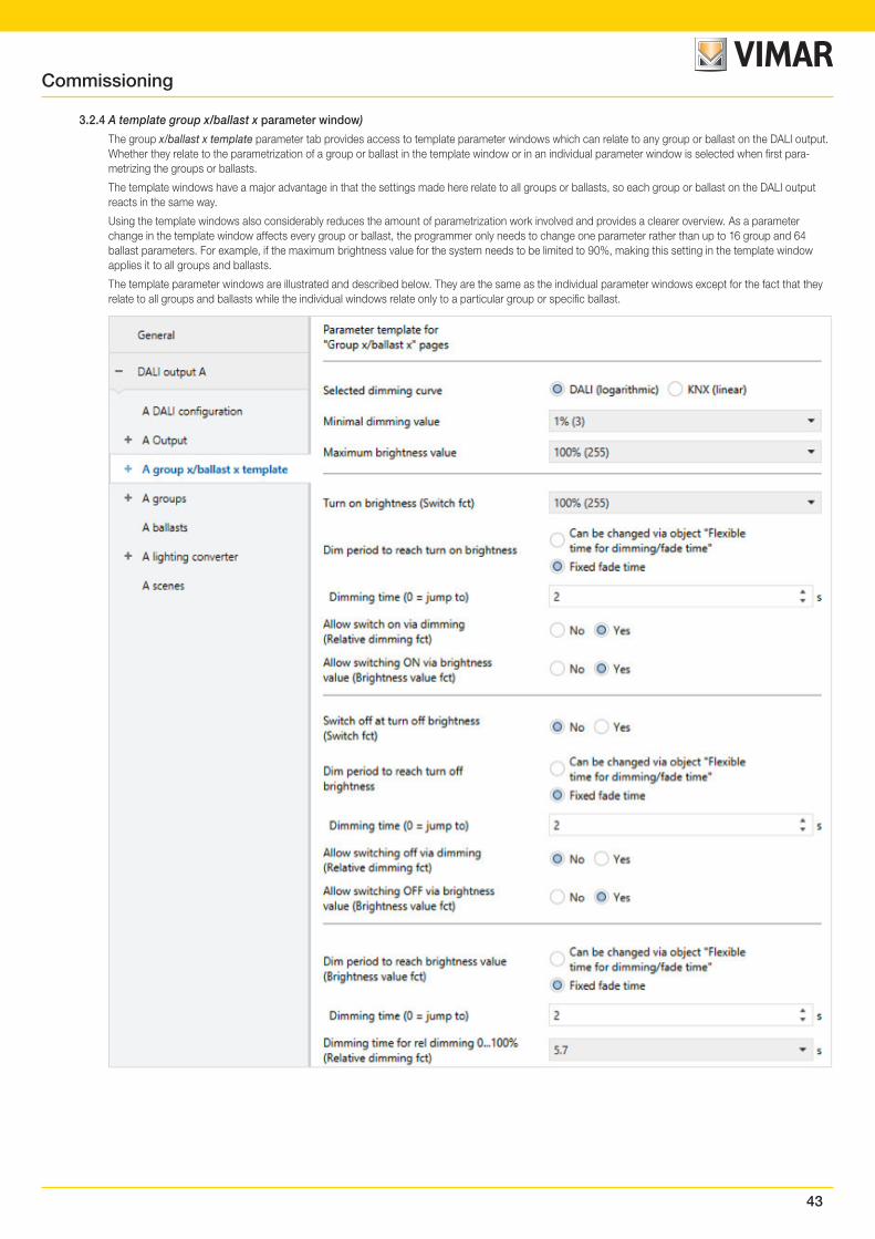
43
3.2.4 A template group x/ballast x parameter window)
The group x/ballast x template parameter tab provides access to template parameter windows which can relate to any group or ballast on the DALI output. Whether they relate to the parametrization of a group or ballast in the template window or in an individual parameter window is selected when first para-metrizing the groups or ballasts.
The template windows have a major advantage in that the settings made here relate to all groups or ballasts, so each group or ballast on the DALI output reacts in the same way.
Using the template windows also considerably reduces the amount of parametrization work involved and provides a clearer overview. As a parameter change in the template window affects every group or ballast, the programmer only needs to change one parameter rather than up to 16 group and 64 ballast parameters. For example, if the maximum brightness value for the system needs to be limited to 90%, making this setting in the template window applies it to all groups and ballasts.
The template parameter windows are illustrated and described below. They are the same as the individual parameter windows except for the fact that they relate to all groups and ballasts while the individual windows relate only to a particular group or specific ballast.
Commissioning
44
Basic settings such as the dimming range and switching and dimming reaction of the DALI output or a group or ballast are made in this parameter window.
Note
References to a central telegram below mean a telegram received via one of the Output A group objects. The function of the group object relates to the whole DALI output including all the connected DALI devices and groups.
References to a group telegram below mean a telegram received via one of the Output A – group y group objects. The function of the group object relates to a DALI group.
References to a ballast or a DALI device below mean a telegram received via one of the Output A – ballast y group objects. The function of the group object relates to a single DALI device or ballast.
Note
If an individual group or ballast telegram is in progress when a central telegram comes in, the former is immediately interrupted and the central telegram for the DALI output is executed. Ballasts or groups which are blocked or under forced operation are not controlled as part of the central telegram, as these two functions have a higher priority. Note that broadcast commands cannot be used under these circumstances, which can cause brightness differences on the output.
If all groups and ballasts are controlled with a central telegram and a telegram for a group or ballast then comes in, this group/ballast is immediately con-trolled by the group/individual command and no longer follows the central command.
The last incoming telegram takes priority and is executed.
Note
If a DALI device is controlled individually, it cannot also be assigned to a DALI group. A DALI device can be controlled either individually via ballast commands or in a group via group commands. Overlapping DALI groups are not supported.
Initially the DALI gateway assumes that group control is in use. If a ballast is to be individually controlled, it must be specifically parametrized in ETS. The bal-last concerned must be enabled in the A ballasts parameter window, which is enabled by selecting individual control in the A DALI configuration parameter window.
If a ballast is assigned to a group but is set to individual control in ETS, or is not set to individual control but is not assigned to a group, this is referred to as a ballast-group conflict.
A ballast-group conflict is indicated as an incorrect state by a yellow caution field in the Vimar software. Depending on which type of control is required (group G or individual S), the device must be assigned to a DALI group or removed from its existing group.
To control individual DALI devices and groups together, a joint KNX group assignment is required.
Selected dimming curve
Options: DALI (logarithmic) KNX (linear)
The dimming curve is the basis for the logarithmic DALI characteristic. You can define whether the KNX setpoint and KNX status value refer to the DALI control value (x-axis) or luminous flux (y-axis).
• DALI: The KNX value refers to the DALI control value (logarithmic).
• KNX: The KNX value refers to the luminous flux (linear).
For more information on dimming curves, see 4.5. DALI dimming curve, p. 136.
Commissioning
45
Minimal dimming value
Options: 100% (255) 99% (252) … 1% (3)
This parameter defines the minimal dimming value adopted by the ballast or group. This value is stored in the DALI devices and thus applies for all func-tions. If the defined minimal dimming value exceeds the maximum brightness value, the 01542 sets it at the maximum.
If the Burn-in lamps function is activated, the group or ballast is operated at 0% (OFF) or 100% brightness, regardless of the minimal dimming/maximum brightness setting.
If a brightness value below the defined minimal dimming value is received via one of the Brightness value group objects, the minimum value is adopted.
The minimal dimming value also applies with dimming and with the Staircase lighting, Slave and Scenes functions.
The DALI output itself has no separate minimal dimming value. The minimal dimming values defined for the group or ballast apply.
Note
When setting brightness values in the individual gateway functions, make sure that they are actually feasible in relation to the basic settings made here for minimal dimming/maximum brightness value. The same applies to the forced operation brightness values and to the parameters set in the Fault parameter window, such as Power-On Level.
Important
The DALI output itself has no separate minimal dimming value. The minimal dimming/maximum brightness values defined for the group or ballast remain ap-plicable even on receipt of a central telegram via the Output A group objects.
Example: Group 1 is assigned a minimal dimming value of 20%, Group 2 10% and a ballast, 15%. If the 01542 receives a central telegram Set brightness value at 5% in this configuration, these group and ballast settings will not change.
Maximum brightness value
Options: 100% (255) 99% (252) … 1% (3)
This parameter defines the maximum brightness value that the ballast or group can adopt. This value is stored in the DALI devices and thus applies for all functions. If a maximum brightness value is set which is below the minimal dimming value, the 01542 sets it to the minimum.
If the Burn-in lamps function is activated, the group, ballast or output is operated at 0% (OFF) or 100% brightness, regardless of the minimal dimming/maxi-mum brightness setting.
If a brightness value above the defined maximum brightness value is received via one of the Brightness value group objects, the maximum value is adopted.
The maximum brightness value also applies with dimming and with the Staircase lighting, Slave and Scenes functions.
Note
The DALI output itself has no separate maximum brightness value. The minimal dimming/maximum brightness values defined for the group or ballast remain applicable even on receipt of a central telegram via the Output A group objects.
Example: Group 1 is assigned a Maximum brightness value of 80%, Group 2 90% and a ballast, 85%. If the 01542 receives a central telegram Set brightness value at 100%, these group and ballast settings will not change.
Commissioning
46
Turn on brightness (Switch fct)
Options: Previous value 100% (255) 99% (252) … 1% (3)
This parameter defines the brightness value used to switch on the ballast, group or DALI output when an ON telegram is received.
Values set outside the thresholds (maximum brightness/minimal dimming value) are automatically adjusted to the maximum or minimum.
If the ballast, group or DALI output receives an ON telegram while at a brightness value other than the turn on brightness – e.g. due to dimming – it adopts the turn on brightness.
• Previous value: The ballast, group or output switches on at the brightness value it was switched off at by the Switch group object.
Note
The previous brightness value is saved with every OFF telegram unless the ballast, group or output is already switched off. If this is the case, the OFF state is not saved as the last brightness value on receipt of another OFF telegram.
If a new OFF telegram is received during dimming down, the current brightness value is saved as the last brightness value.
In the event of a KNX voltage failure, download or restart, the previous brightness value is lost, and set to a turn on brightness of 100%.
Separate previous brightness values are saved for the ballast/group and the output.This means that if the output is dimmed or switched on/off by a central telegram, the previous brightness value for the ballast/group remains unchanged.
Dim period to reach turn on brightness
Options: Fixed fade time Can be changed via object "Flexible time for dimming/fade time"
This group object defines whether the dimming time can be changed via KNX.
• Fixed fade time: Dimming time is permanently set and cannot be changed via the KNX.
• Can be changed via object "Flexible time for dimming/fade time": Dimming time can be changed via the KNX using the Flexible time for dimming/fade time group object.
Note
Flexible dimming time is received via the Output A Flexible time for dimming/fade time group object and affects various output functions:
• Dimming time for turn on/off value
• Dimming time for brightness value
• Dimming time for slave brightness value
• Scene transition time
To use the Flexible dimming time function you first need to enable the output's Flexible time for dimming/fade time group object in the A Output/Func-tions parameter window. You also need to select the function for the parameter that can be changed via KNX. We recommend that you only change one time via KNX. Otherwise the dimming time has to be rewritten on the ballast every time a function is called, which impairs function performance.
Selection of Fixed fade time option:
Dependent parameters:
Commissioning
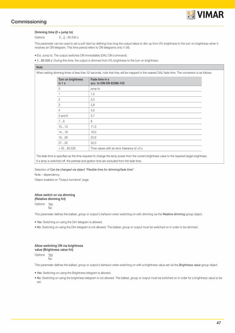
47
Dimming time (0 = jump to)
Options: 0…2…65.535 s
This parameter can be used to set a soft start by defining how long the output takes to dim up from 0% brightness to the turn on brightness when it receives an ON telegram. This time period refers to ON telegrams only (1 bit).
• 0 s: Jump to. The output switches ON immediately (DALI ON command).
• 1…65.535 s: During this time, the output is dimmed from 0% brightness to the turn on brightness.
Note
When setting dimming times of less than 32 seconds, note that they will be mapped to the nearest DALI fade time. The conversion is as follows:
Turn on brightnessin 1 s
Fade time in sacc. to DIN EN 62386-102
0 jump to
1 1,0
2 2,0
3 2,8
4 4,0
5 and 6 5,7
7…9 8
10…13 11,3
14…18 16,0
19…26 22,6
27…32 32,0
> 32…65.535 Time values with an error tolerance of ±3 s
The fade time is specified as the time required to change the lamp power from the current brightness value to the required target brightness.
If a lamp is switched off, the preheat and ignition time are excluded from the fade time.
Selection of Can be changed via object "Flexible time for dimming/fade time":
Note – dependency:
Object enabled on "Output functions" page
Allow switch on via dimming(Relative dimming fct)
Options: Yes No
This parameter defines the ballast, group or output's behavior when switching on with dimming via the Relative dimming group object.
• Yes: Switching on using the Dim telegram is allowed.
• No: Switching on using the Dim telegram is not allowed. The ballast, group or output must be switched on in order to be dimmed.
Allow switching ON via brightnessvalue (Brightness value fct)
Options: Yes No
This parameter defines the ballast, group or output's behavior when switching on with a brightness value set via the Brightness value group object.
• Yes: Switching on using the Brightness telegram is allowed.
• No: Switching on using the brightness telegram is not allowed. The ballast, group or output must be switched on in order for a brightness value to be set.
Commissioning
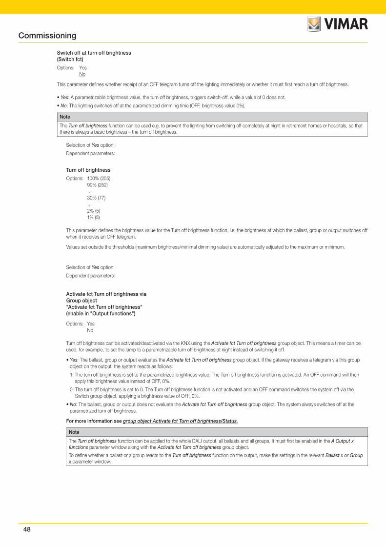
48
Switch off at turn off brightness(Switch fct)
Options: Yes No
This parameter defines whether receipt of an OFF telegram turns off the lighting immediately or whether it must first reach a turn off brightness.
• Yes: A parametrizable brightness value, the turn off brightness, triggers switch-off, while a value of 0 does not.
• No: The lighting switches off at the parametrized dimming time (OFF, brightness value 0%).
Note
The Turn off brightness function can be used e.g. to prevent the lighting from switching off completely at night in retirement homes or hospitals, so that there is always a basic brightness – the turn off brightness.
Selection of Yes option:
Dependent parameters:
Turn off brightness
Options: 100% (255) 99% (252) … 30% (77) … 2% (5) 1% (3)
This parameter defines the brightness value for the Turn off brightness function, i.e. the brightness at which the ballast, group or output switches off when it receives an OFF telegram.
Values set outside the thresholds (maximum brightness/minimal dimming value) are automatically adjusted to the maximum or minimum.
Selection of Yes option:
Dependent parameters:
Activate fct Turn off brightness viaGroup object"Activate fct Turn off brightness"(enable in "Output functions")
Options: Yes No
Turn off brightness can be activated/deactivated via the KNX using the Activate fct Turn off brightness group object. This means a timer can be used, for example, to set the lamp to a parametrizable turn off brightness at night instead of switching it off.
• Yes: The ballast, group or output evaluates the Activate fct Turn off brightness group object. If the gateway receives a telegram via this group object on the output, the system reacts as follows:
1: The turn off brightness is set to the parametrized brightness value. The Turn off brightness function is activated. An OFF command will then apply this brightness value instead of OFF, 0%.
0: The turn off brightness is set to 0. The Turn off brightness function is not activated and an OFF command switches the system off via the Switch group object, applying a brightness value of OFF, 0%.
• No: The ballast, group or output does not evaluate the Activate fct Turn off brightness group object. The system always switches off at the parametrized turn off brightness.
For more information see group object Activate fct Turn off brightness/Status.
Note
The Turn off brightness function can be applied to the whole DALI output, all ballasts and all groups. It must first be enabled in the A Output x functions parameter window along with the Activate fct Turn off brightness group object.
To define whether a ballast or a group reacts to the Turn off brightness function on the output, make the settings in the relevant Ballast x or Group x parameter window.
Commissioning
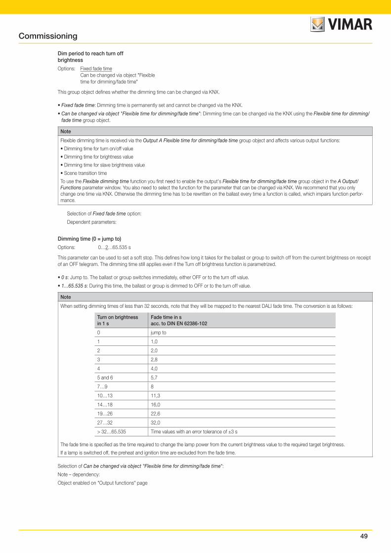
49
Dim period to reach turn offbrightness
Options: Fixed fade time Can be changed via object "Flexible time for dimming/fade time"
This group object defines whether the dimming time can be changed via KNX.
• Fixed fade time: Dimming time is permanently set and cannot be changed via the KNX.
• Can be changed via object "Flexible time for dimming/fade time": Dimming time can be changed via the KNX using the Flexible time for dimming/fade time group object.
Note
Flexible dimming time is received via the Output A Flexible time for dimming/fade time group object and affects various output functions:
• Dimming time for turn on/off value
• Dimming time for brightness value
• Dimming time for slave brightness value
• Scene transition time
To use the Flexible dimming time function you first need to enable the output's Flexible time for dimming/fade time group object in the A Output/Functions parameter window. You also need to select the function for the parameter that can be changed via KNX. We recommend that you only change one time via KNX. Otherwise the dimming time has to be rewritten on the ballast every time a function is called, which impairs function perfor-mance.
Selection of Fixed fade time option:
Dependent parameters:
Dimming time (0 = jump to)
Options: 0…2…65.535 s
This parameter can be used to set a soft stop. This defines how long it takes for the ballast or group to switch off from the current brightness on receipt of an OFF telegram. The dimming time still applies even if the Turn off brightness function is parametrized.
• 0 s: Jump to. The ballast or group switches immediately, either OFF or to the turn off value.
• 1…65.535 s: During this time, the ballast or group is dimmed to OFF or to the turn off value.
Note
When setting dimming times of less than 32 seconds, note that they will be mapped to the nearest DALI fade time. The conversion is as follows:
Turn on brightnessin 1 s
Fade time in sacc. to DIN EN 62386-102
0 jump to
1 1,0
2 2,0
3 2,8
4 4,0
5 and 6 5,7
7…9 8
10…13 11,3
14…18 16,0
19…26 22,6
27…32 32,0
> 32…65.535 Time values with an error tolerance of ±3 s
The fade time is specified as the time required to change the lamp power from the current brightness value to the required target brightness.
If a lamp is switched off, the preheat and ignition time are excluded from the fade time.
Selection of Can be changed via object "Flexible time for dimming/fade time":
Note – dependency:
Object enabled on "Output functions" page
Commissioning
50
Allow switching off via dimming(Relative dimming fct)
Options: Yes No
This parameter defines the behavior of the ballast or group when switching off during dimming.
• Yes: Switch off using the Dim telegram is allowed.
• No: Switch off using the Dim telegram is not allowed. The ballast or group dims to the minimal dimming value and stops there. It must be switched off using the Switch group object, or if allowed, via the Brightness value group object.
Allow switching OFF via brightnessvalue (Brightness value fct)
Options: Yes No
This parameter defines the ballast or group's behavior when switching off with a brightness value set via the Brightness value group object.
• Yes: Switch off using the brightness telegram is allowed.
• No: Switch off using the brightness telegram is not allowed. The ballast or group must be switched off using the Switch group object, or if allowed, dimmed down.
Dim period to reach brightness value(Brightness value fct.)
Options: Fixed fade time Can be changed via object "Flexible time for dimming/fade time"
This group object defines whether the dimming time can be changed via KNX. The dim period to reach brightness value is the time required to transition from the current brightness value to the new one.
• Fixed fade time: Dimming time is permanently set and cannot be changed via the KNX.
• Can be changed via object "Flexible time for dimming/fade time": Dimming time can be changed via the KNX using the Flexible time for dimming/fade time group object.
Note
Flexible dimming time is received via the Output A Flexible time for dimming/fade time group object and affects various output functions:
• Dimming time for turn on/off value
• Dimming time for brightness value
• Dimming time for slave brightness value
• Scene transition time
To use the Flexible dimming time function you first need to enable the output's Flexible time for dimming/fade time group object in the A Output/Func-tions parameter window. You also need to select the function for the parameter that can be changed via KNX. We recommend that you only change one time via KNX. Otherwise the dimming time has to be rewritten on the ballast every time a function is called, which impairs function performance.
Selection of Fixed fade time option:
Dependent parameters:
Dimming time (0 = jump to)
Options: 0…2…65.535 s
This parameter defines how long it takes to dim up to the set brightness value. This time only relates to the output's Brightness value telegram (8-bit).
• 0 s: Jump to. The output immediately switches to the brightness value.
• 1…65.535 s: During this time, the output is dimmed up to the brightness value.
Commissioning
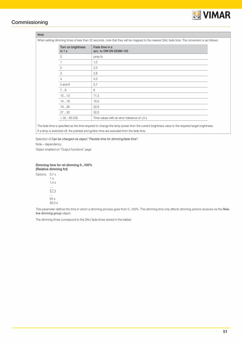
51
Note
When setting dimming times of less than 32 seconds, note that they will be mapped to the nearest DALI fade time. The conversion is as follows:
Turn on brightnessin 1 s
Fade time in sacc. to DIN EN 62386-102
0 jump to
1 1,0
2 2,0
3 2,8
4 4,0
5 and 6 5,7
7…9 8
10…13 11,3
14…18 16,0
19…26 22,6
27…32 32,0
> 32…65.535 Time values with an error tolerance of ±3 s
The fade time is specified as the time required to change the lamp power from the current brightness value to the required target brightness.
If a lamp is switched off, the preheat and ignition time are excluded from the fade time.
Selection of Can be changed via object "Flexible time for dimming/fade time":
Note – dependency:
Object enabled on "Output functions" page
Dimming time for rel dimming 0...100%(Relative dimming fct)
Options: 0,7 s 1 s 1,4 s … 5,7 s … 64 s 90,5 s
This parameter defines the time in which a dimming process goes from 0...100%. This dimming time only affects dimming actions received via the Rela-tive dimming group object.
The dimming times correspond to the DALI fade times stored in the ballast.
Commissioning
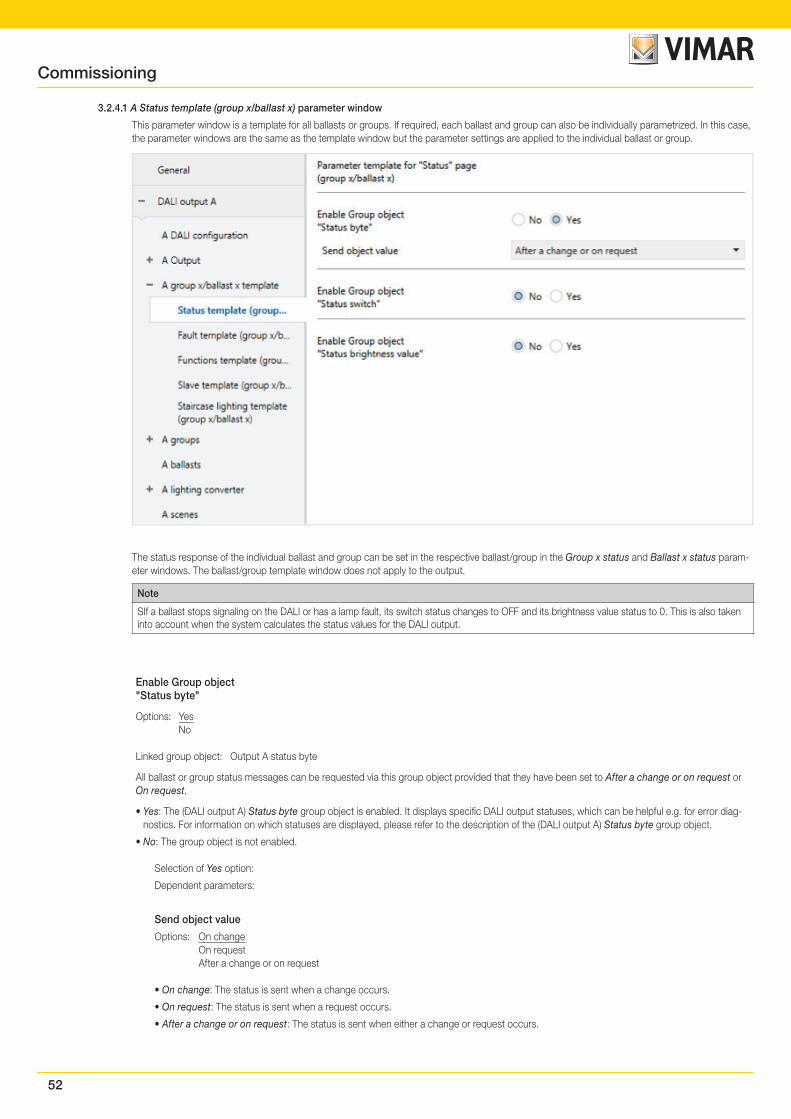
52
3.2.4.1 A Status template (group x/ballast x) parameter window
This parameter window is a template for all ballasts or groups. If required, each ballast and group can also be individually parametrized. In this case, the parameter windows are the same as the template window but the parameter settings are applied to the individual ballast or group.
The status response of the individual ballast and group can be set in the respective ballast/group in the Group x status and Ballast x status param-eter windows. The ballast/group template window does not apply to the output.
Note
SIf a ballast stops signaling on the DALI or has a lamp fault, its switch status changes to OFF and its brightness value status to 0. This is also taken into account when the system calculates the status values for the DALI output.
Enable Group object"Status byte"
Options: Yes No
Linked group object: Output A status byte
All ballast or group status messages can be requested via this group object provided that they have been set to After a change or on request or On request.
• Yes: The (DALI output A) Status byte group object is enabled. It displays specific DALI output statuses, which can be helpful e.g. for error diag-nostics. For information on which statuses are displayed, please refer to the description of the (DALI output A) Status byte group object.
• No: The group object is not enabled.
Selection of Yes option:
Dependent parameters:
Send object value
Options: On change On request After a change or on request
• On change: The status is sent when a change occurs.
• On request: The status is sent when a request occurs.
• After a change or on request: The status is sent when either a change or request occurs.
Commissioning
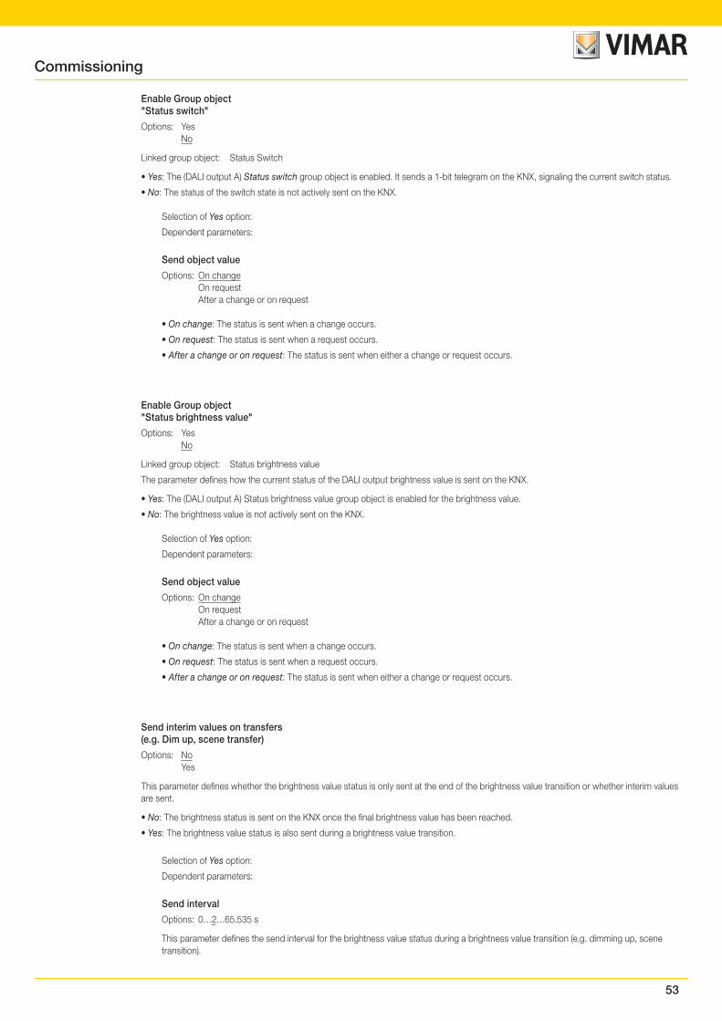
53
Enable Group object"Status switch"
Options: Yes No
Linked group object: Status Switch
• Yes: The (DALI output A) Status switch group object is enabled. It sends a 1-bit telegram on the KNX, signaling the current switch status.
• No: The status of the switch state is not actively sent on the KNX.
Selection of Yes option:
Dependent parameters:
Send object value
Options: On change On request After a change or on request
• On change: The status is sent when a change occurs.
• On request: The status is sent when a request occurs.
• After a change or on request: The status is sent when either a change or request occurs.
Enable Group object"Status brightness value"
Options: Yes No
Linked group object: Status brightness value
The parameter defines how the current status of the DALI output brightness value is sent on the KNX.
• Yes: The (DALI output A) Status brightness value group object is enabled for the brightness value.
• No: The brightness value is not actively sent on the KNX.
Selection of Yes option:
Dependent parameters:
Send object value
Options: On change On request After a change or on request
• On change: The status is sent when a change occurs.
• On request: The status is sent when a request occurs.
• After a change or on request: The status is sent when either a change or request occurs.
Send interim values on transfers(e.g. Dim up, scene transfer)
Options: No Yes
This parameter defines whether the brightness value status is only sent at the end of the brightness value transition or whether interim values are sent.
• No: The brightness status is sent on the KNX once the final brightness value has been reached.
• Yes: The brightness value status is also sent during a brightness value transition.
Selection of Yes option:
Dependent parameters:
Send interval
Options: 0…2…65.535 s
This parameter defines the send interval for the brightness value status during a brightness value transition (e.g. dimming up, scene transition).
Commissioning
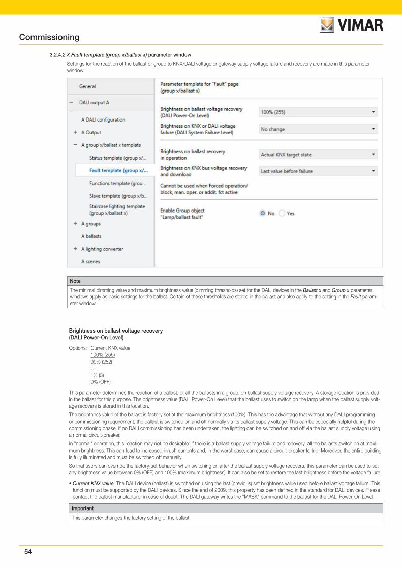
54
3.2.4.2 X Fault template (group x/ballast x) parameter window
Settings for the reaction of the ballast or group to KNX/DALI voltage or gateway supply voltage failure and recovery are made in this parameter window.
Note
The minimal dimming value and maximum brightness value (dimming thresholds) set for the DALI devices in the Ballast x and Group x parameter windows apply as basic settings for the ballast. Certain of these thresholds are stored in the ballast and also apply to the setting in the Fault param-eter window.
Brightness on ballast voltage recovery(DALI Power-On Level)
Options: Current KNX value 100% (255) 99% (252) … 1% (3) 0% (OFF)
This parameter determines the reaction of a ballast, or all the ballasts in a group, on ballast supply voltage recovery. A storage location is provided in the ballast for this purpose. The brightness value (DALI Power-On Level) that the ballast uses to switch on the lamp when the ballast supply volt-age recovers is stored in this location.
The brightness value of the ballast is factory set at the maximum brightness (100%). This has the advantage that without any DALI programming or commissioning requirement, the ballast is switched on and off normally via its ballast supply voltage. This can be especially helpful during the commissioning phase. If no DALI commissioning has been undertaken, the lighting can be switched on and off via the ballast supply voltage using a normal circuit-breaker.
In "normal" operation, this reaction may not be desirable: If there is a ballast supply voltage failure and recovery, all the ballasts switch on at maxi-mum brightness. This can lead to increased inrush currents and, in the worst case, can cause a circuit-breaker to trip. Moreover, the entire building is fully illuminated and must be switched off manually.
So that users can override the factory-set behavior when switching on after the ballast supply voltage recovers, this parameter can be used to set any brightness value between 0% (OFF) and 100% (maximum brightness). It can also be set to restore the last brightness before the voltage failure.
• Current KNX value: The DALI device (ballast) is switched on using the last (previous) set brightness value used before ballast voltage failure. This function must be supported by the DALI devices. Since the end of 2009, this property has been defined in the standard for DALI devices. Please contact the ballast manufacturer in case of doubt. The DALI gateway writes the "MASK" command to the ballast for the DALI Power-On Level.
Important
This parameter changes the factory setting of the ballast.
Commissioning
55
Brightness on KNX or DALI voltagefailure (DALI System Failure Level)
Options: Maximum brightness value (100%) Min. brightness value (1%) OFF No change
This parameter defines how the ballast or group ballasts react if the gateway cannot communicate via the KNX due to a KNX voltage failure, or if there is a DALI voltage failure (e.g. a DALI short circuit or a gateway supply voltage failure).
• No change: The brightness of the ballast/group ballasts does not change. DALI devices that are switched off remain off. The timer functions, e.g. Staircase lighting and Burn-in are discontinued.
• Maximum brightness value (100%): The ballast/group ballasts switch on at or dim to the maximum brightness value.
• Min. brightness value (1%): The ballast/group ballasts switch on at or dim to the minimum brightness value.
• OFF: The ballast/group ballasts switch off.
Note
The factory default setting of the ballast is changed with this parameter (system failure level).
Note
Reaction between (ballast) power on and absent DALI voltage (interface failure/system failure)
According to the DALI standard, no exact priority has been defined between these two functions. The reaction depends on when the ballast is ready to receive again and when it detects that there is no DALI voltage. Both depend on the electronics and firmware of the ballast.
In most cases, the following behavior is expected:
After the ballast supply voltage is applied, the power-on level is started by the ballast. However, a few hundred ms later, the ballast will detect that there is no DALI voltage. This in turn triggers the system fault Level (no DALI voltage). Therefore visually, the user will only detect the system fault (the parametrized reaction on a DALI voltage failure).
Brightness on ballast recoveryin operation
Options: Actual KNX target state Maximum brightness value (100%) Min. brightness value (1%) OFF No change
This parameter defines how a failed ballast reacts if it is has already been detected by the gateway and does not respond (has failed) and is de-tected by the gateway again.
• Actual KNX target state: The ballast adopts the brightness value it would have adopted on receiving a KNX telegram had it not failed.
• No change: The ballast does not change its current brightness value after recovery.
• Maximum brightness value (100%): After recovery, the ballast switches on at or is dimmed to the maximum brightness value.
• Min. brightness value (1%): After recovery, the ballast switches on at or is dimmed to the minimum brightness value.
• OFF (0%): The ballast switches off after recovery.
Note
The minimum and maximum dimming values (dimming thresholds) still remain valid.
The Scene, Staircase lighting, Block and Forced operation functions as well as dimming processes are interrupted. The state of the timer func-tions after a download or after KNX bus voltage recovery must be set separately in the appropriate timer function parameter window.
The supply voltage applied to DALI equipment, e.g. ballasts, is a prerequisite for the equipment to respond correctly.
Note
Interaction between Power-On and DALI voltage recovery (interface failure):
After the supply voltage is restored to the DALI ballast, its Power-On level is set. This brightness value is stored in the ballast and is set by the DALI device (ballast) once its supply voltage recovers.
Simultaneously, the gateway starts to receive responses from the DALI device (ballast) again on the DALI. The Brightness on ballast recovery in operation parameter takes effect at this point, setting the brightness value parametrized here.
If one setting has a higher priority than the other, the other must be set to No change.
Commissioning
56
Brightness on KNX bus voltage recoveryand download
Options: Last value before failure Maximum brightness value (100%) Min. brightness value (1%) OFF No change
This parameter defines how the ballast/group ballasts react after a download, on KNX bus voltage recovery, or after light controller supply voltage recovery.
• No change: The brightness of the ballast/group does not change. Ballasts or groups that are switched off remain off.
• Last value before failure: The ballast/group is restored to its pre-failure state. To be reinstated after KNX bus voltage recovery the brightness value must have been set for at least two seconds before a KNX voltage failure or a download.
• Maximum brightness value (100%): The ballast/group switches on at or dims to the maximum brightness value.
• Min. brightness value (1%): The ballast/group switches on at or dims to the minimum brightness value.
• OFF (0%): The ballast/group switches off.
Note
The minimal dimming/maximum brightness values (dimming thresholds) still remain valid. If the set brightness values are outside the dimming thresholds, the threshold value is adopted.
The Scene, Staircase lighting, Block and Forced operation functions as well as dimming processes are interrupted. The state of the functions after a download or after KNX bus voltage recovery must be set separately in the appropriate function parameter window.
For the correct response to trigger, the DALI equipment must have a voltage applied and must be operated according to the standard.
Enable Group object"Lamp/ballast fault"
Options: Yes No
Linked group object: Lamp/ballast fault
This group object indicates a fault in the ballast or group. The fault type (lamp or ballast) is parametrizable.
• Yes: The group object is enabled.
• No: The group object is not enabled.
The following parameter is used to select the fault type that the Fault group object will indicate.
Selection of Yes option:
Dependent parameters:
Content of Group object
Options: Lamp/ballast fault Lamp fault Ballast fault
This parameter determines which fault is provided on the Fault group object.
• Lamp fault: The Fault group object sends information on the KNX indicating whether the ballast/a group ballast has a lamp fault.
• Ballast fault: The Fault group object sends information on the KNX indicating whether the ballast/a group ballast has a ballast fault.
• Lamp or ballast fault: The Fault group object sends information on the KNX indicating whether the ballast/a group ballast has a lamp or ballast fault.
Note
To detect a ballast fault correctly the gateway needs to monitor all DALI devices. Monitoring can be triggered either via the Detect ballasts group object or via the commissioning tool. There is no automatic detection, e.g. after a KNX bus voltage recovery or gateway supply voltage recovery.
Activation should be carried out straight after commissioning or when adding or removing DALI devices.
The DALI devices must be properly installed and have a supply voltage.
At what point a ballast fault is detected depends on when the gateway polls the DALI devices. This interval can be set via the Pause between two DALI QUERY polls parameter in the Output A – A DALI configuration parameter window.
Commissioning
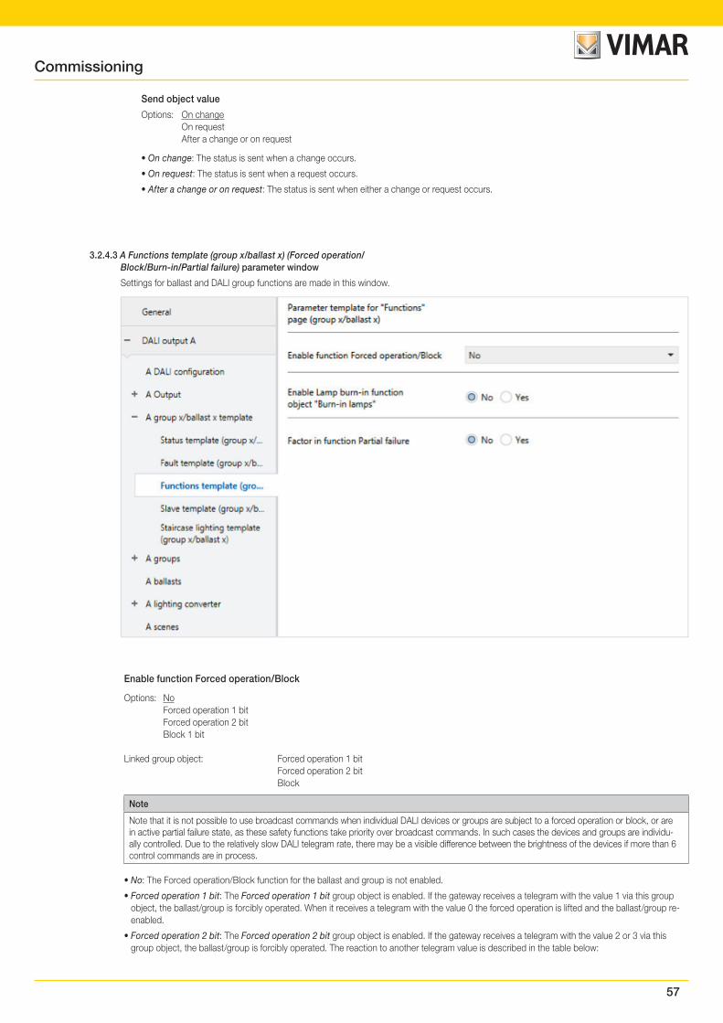
57
Send object value
Options: On change On request After a change or on request
• On change: The status is sent when a change occurs.
• On request: The status is sent when a request occurs.
• After a change or on request: The status is sent when either a change or request occurs.
3.2.4.3 A Functions template (group x/ballast x) (Forced operation/Block/Burn-in/Partial failure) parameter window
Settings for ballast and DALI group functions are made in this window.
Enable function Forced operation/Block
Options: No Forced operation 1 bit Forced operation 2 bit Block 1 bit
Linked group object: Forced operation 1 bit Forced operation 2 bit Block
Note
Note that it is not possible to use broadcast commands when individual DALI devices or groups are subject to a forced operation or block, or are in active partial failure state, as these safety functions take priority over broadcast commands. In such cases the devices and groups are individu-ally controlled. Due to the relatively slow DALI telegram rate, there may be a visible difference between the brightness of the devices if more than 6 control commands are in process.
• No: The Forced operation/Block function for the ballast and group is not enabled.
• Forced operation 1 bit: The Forced operation 1 bit group object is enabled. If the gateway receives a telegram with the value 1 via this group object, the ballast/group is forcibly operated. When it receives a telegram with the value 0 the forced operation is lifted and the ballast/group re-enabled.
• Forced operation 2 bit: The Forced operation 2 bit group object is enabled. If the gateway receives a telegram with the value 2 or 3 via this group object, the ballast/group is forcibly operated. The reaction to another telegram value is described in the table below:
Commissioning
58
Value Bit 1 Bit 0 Status Description
0 0 0 Enabled If the Forced operation group object receives a telegram with the value 0 (binary 00) or 1 (binary 01), the group/ballast is enabled and can be controlled via various group objects.1 0 1 Enabled
2 1 0 Forced OFF
If the Forced operation group object receives a telegram with the value 2 (binary 10), the group/ballast is forced OFF and remains inhibited until Forced operation is deacti-vated.
Control via another group object is ignored as long as Forced operation is active. Tel-egrams are updated in the background and the end values are saved.
When Forced operation is deactivated the brightness value, which is continuously updated in the background, is set.
3 1 1 Forced ON
If the Forced operation group object receives a telegram with the value 3 (binary 11), the group/ballast is forced ON at the parametrized brightness value and remains inhib-ited until Forced operation is deactivated.
Control via another group object is ignored as long as Forced operation is active. Tel-egrams are updated in the background and the end values are saved.
When Forced operation is deactivated the brightness value, which is continuously updated in the background, is set.
The transition to forced operation is a jump at the DALI fade time of 0.7 s.
• Block 1 bit: The Block function for the ballast/group is enabled. The Block function is activated by a telegram with the value 1 and deactivated with the value 0. The ballast/group can be blocked using this group object so that it cannot be changed via the bus.
The current brightness value of the ballast/group is frozen. Incoming telegrams are processed in the background. Dimming processes are not simulated in the background; with time sequences the end brightness value is immediately memorized. When the block is removed, the value updated in the background is set.
A block during a dimming up or down process or scene operation interrupts the dimming process and freezes the current brightness value. A block during the Staircase lighting or Slave function immediately blocks the ballast/group and freezes the brightness value. After unblocking, the Staircase lighting function continues in standby.
If Slave mode was active before the block, it will be re-established.
Forced operation and Block have a higher priority than manual operation.
During DALI commissioning, the Block and Forced operation functions are deactivated if the Vimar software is in configuration mode.
Selection of Forced operation 1 bit:
Dependent parameters:
Brightness value when switched onby force
Options: 100% (255) 99% (252) … 1% (3) 0% (OFF)
This parameter defines the brightness value used to switch on the ballast or group during activated forced operation. Forced switch off of the or the group or ballast is also parametrizable..
Note
The minimal dimming value and maximum brightness value (dimming thresholds) set for the DALI devices in the Ballast x and Group x parameter windows apply as basic settings for the ballast. Certain of these thresholds are stored in the ballast and also apply to all functions. Therefore, when setting the brightness value that will apply during forced operation, make sure that it is feasible given the basic ballast settings.
Selection of Forced operation 2 bit:
Dependent parameters:
Commissioning
59
Brightness value when switched onby force
Options: 100% (255) 99% (252) … 1% (3) 0% (OFF)
This parameter defines the brightness value used to switch on the ballast or group during activated forced operation. Forced switch off of the or the group or ballast is also parametrizable.
How does forced operation work?
The active Forced operation, irrespective of whether it is 1 bit or 2 bit control, has an influence on the overall reaction of the ballast. When Forced operation is recalled, the brightness value parametrized in ETS is set. Any Dim telegrams or slave or staircase lighting functions etc. in progress are interrupted.
Brightness values received during Forced operation are not set, although they are processed in the background and saved. Switch telegrams and slave values are also saved in the background. Relative dimming telegrams and dimming ramps are ignored. With time sequences (e.g. Staircase lighting or Scene), the end brightness value is immediately memorized. When the block is removed, the value updated in the back-ground is set.
When Forced operation ends, the brightness value updated in the background is set. The ballast or group returns to the state it was in before forced operation. If an additional function was active, e.g. Staircase lighting or Slave, it will also be active after Forced operation. If the Staircase lighting function was activated before Forced operation, it goes into standby when Forced operation/Block is removed. If the Slave function was activated before Forced operation, it continues once forced operation is removed and responds to the master again.
State of forced operationon bus voltage recovery
Options: Inactive Switch on by force State before KNX voltage failure
This parameter defines the state of a forced operation after bus voltage recovery.
• Inactive: The ballast/group is enabled after bus voltage recovery and is no longer subject to Forced operation. Any parametrized Staircase lighting functions will be active in standby if they were activated before Forced operation. A slave will start responding to the master again if it was activated before Forced operation.
• Switch on by force: The ballast/group is forcibly operated and switched on at the brightness parametrized in Brightness value when switched on by force.
• State before KNX voltage failure: The ballast/group is restored to the state it was in before the voltage failure.
Selection of Block 1 bit option:
Dependent parameters:
Disable state onKNX bus voltage recovery
Options: Not disabled Disabled State before KNX voltage failure
This parameter defines the disable state after a KNX bus voltage recovery.
• Not disabled: The ballast/group is enabled after KNX bus voltage recovery and is no longer subject to the Block. Any parametrized Staircase lighting or Slave functions will be active if they were activated before the Block.
• Disabled:: The group/ballast is disabled after KNX bus voltage recovery and retains the brightness value parametrized for this event.
• State before KNX voltage failure: The ballast/group retains the state it was in before the KNX voltage failure.
Commissioning
60
Enable Lamp burn-in functionobject "Burn-in lamps"
Options: Yes No
Linked group object: Burn-in lamp
This parameter enables the Burn-in function for a ballast or group. The function itself can be activated by ballast or group via the ballast x/group x Burn-in lamp group object, or for all ballast/groups together via the Output x group object Burn-in lamp/Status. This group object is enabled in the Output A Functions parameter window. The Output A Burn-in lamps/Status group object only affects the ballasts and groups which are set to respond to it. This property is parametrized for groups and ballasts in the Group x functions or Ballast x functions parameter window.
Note
Continuous dimming of vapor filled lamps which are not burnt in can prevent the lamp from reaching its maximum defined brightness, making the required brightness value in the area unachievable.
To guarantee maximum lamp life and correct lamp function in the dimmed state, many vapor filled lamps must be operated for a certain number of hours at 100% brightness during initial operation before they can be permanently dimmed.
For detailed information please see the technical data for the lamps.
• Yes: The Burn-in function for the ballast/group and the Burn-in lamp group object are enabled. Burn-in is started with the Burn-in lamp group object or the Vimar software (not download). Alternatively it can be started via the Output A Burn-in lamp/Status group object.
• No: The Burn-in function for the ballast/group is not enabled.
Selection of Yes option:
Dependent parameters:
Lamp burn-in time in hours [1…255]
Options: 1…100…255
This parameter defines the time period for the Burn-in function. Until this time has elapsed, the ballast/group can only be operated at 100% and OFF on the DALI output, i.e. at every set brightness value other than 0%, the lamp is switched on at 100% brightness.
Once the burn-in time has run or the Burn-in function is deactivated, e.g. if a telegram with the value 0 is received via the Burn-in lamp group object, the lamp can be dimmed as usual.
The burn-in time is only counted if a DALI device is connected to the output, ready for operation with a supply voltage, and switched on.
The burn-in time function remains activated in the event of a KNX bus voltage failure. The time is not lost but stops counting during the failure.
With a gateway supply voltage failure, the remaining burn-in time is saved and reused after gateway supply voltage recovery. This also applies after an ETS download.
Reaction with activated Burn-in function
If a telegram with the value 1 is received via the Burn-in lamp group object, the gateway activates the Burn-in function and sets the pro-grammed burn-in time. The function can also be activated with the Vimar software or via a channel group object.
During the Burn-in function, the lamp can only adopt the state 0% (OFF) or 100% (ON). Every device has its own "burn-in counter", which decrements when the device is switched on. The counter has a counting interval of five minutes, i.e. if the lamp has been switched on for five minutes, the burn-in time is reduced by five minutes. As soon as a device has completed its burn-in time, it is enabled for normal dim-ming operation.
The internal burn-in counter has a timer with five-minute intervals and a maximum value of 255 hours.
Reaction on KNX bus voltage failureand gateway supply voltage failure
The elapsed burn-in time is retained and continues to count down after KNX bus voltage recovery and gateway supply voltage recovery.
Commissioning
61
Status of burn-in
Options: No Yes
Linked group object: Burn-in lamp/Status
The gateway features an option to send the status of the Burn-in function on the KNX with the Burn-in lamp/Status group object.
• No: No status message is sent for the Burn-in function.
• Yes: The Burn-in lamps group object changes to the Burn-in lamp/Status group object. If this group object receives an ON telegram, the Burn-in function starts and the status is sent on the KNX.
Selection of Yes:
Dependent parameters:
Send object value
Options: On change On request After a change or on request
• On change: The status is sent when a change occurs.
• On request: The status is sent when a request occurs.
• After a change or on request: The status is sent when either a change or request occurs.
Factor in function Partial failure"
Options: Yes No
• Yes: The Reaction on partial failure function is taken into account for the ballast or group.
• No: The Reaction on partial failure function is not taken into account for the ballast or group.
Partial failure can be sent and received internally on the DALI output or externally via the Activate partial failure/Status group object. The relevant settings are made in the A Output functions parameter window. Properties in the event of a partial failure are also set here. Partial failure is de-pendent on the number of lamp/ballast faults, on whether emergency lighting is activated (emergency lighting converter in emergency mode) and on DALI voltage faults.
Brightness valueduring partial failure
Options: 100% (255) 99% (252) … 1% (3) 0% (0)
This parameter defines the brightness value that controls the ballast or group during partial failure.
Note
Note that it is not possible to use broadcast commands when individual DALI devices or groups are subject to a forced operation or block, or are in active partial failure state, as these safety functions take priority over broadcast commands. In such cases the devices and groups are individu-ally controlled. Due to the relatively slow DALI telegram rate, there may be a visible difference between the brightness of the devices if more than 6 control commands are in process.
Commissioning
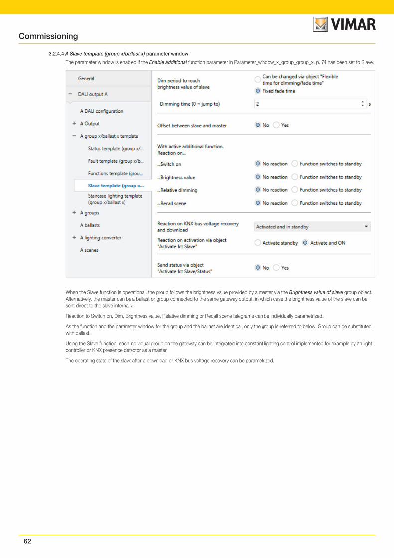
62
3.2.4.4 A Slave template (group x/ballast x) parameter window
The parameter window is enabled if the Enable additional function parameter in Parameter_window_x_group_group_x, p. 74 has been set to Slave.
When the Slave function is operational, the group follows the brightness value provided by a master via the Brightness value of slave group object. Alternatively, the master can be a ballast or group connected to the same gateway output, in which case the brightness value of the slave can be sent direct to the slave internally.
Reaction to Switch on, Dim, Brightness value, Relative dimming or Recall scene telegrams can be individually parametrized.
As the function and the parameter window for the group and the ballast are identical, only the group is referred to below. Group can be substituted with ballast.
Using the Slave function, each individual group on the gateway can be integrated into constant lighting control implemented for example by an light controller or KNX presence detector as a master.
The operating state of the slave after a download or KNX bus voltage recovery can be parametrized.
Commissioning
63
Note
If the gateway receives a central switch, relative dimming or Brightness value telegram via a group object for the DALI output while Slave mode is running, the telegram is executed. The slave goes to standby. To respond to the master again the group has to receive an ON telegram via the Switch group object or be reactivated by the Activate fct Slave group object
Note
The additional function Slave can adopt three operating states:
Additional function Slave is not active: The additional function is deactivated via its Activate fct Slave group object if a telegram with the value 0 is received. In the deactivated state the group reacts like a normal group. The properties set in the Group x parameter window apply. In this state, an ON telegram does not start the additional function. The group only switches to slave state after a telegram with the value 1 is received on the Activate fct Slave group object.
Additional function is active in standby: The additional function is active but has been interrupted, e.g. by an OFF telegram. The group is in standby. An ON telegram (telegram on the Switch group object) retriggers the additional function and the slave starts responding to the Brightness value of slave group object or internally to its master again.
Additional function running: The Slave function receives its brightness value from the master. This can be direct, internally from a ballast or group on the output without a KNX connection, or via the Brightness value of slave group object. The master is assigned in the Group x Slave parameter window using the Source (slave is controlled via) parameter.
Depending on individual parametrization, the active Slave function can be put on standby by a Switch-on, Brightness value, Relative dimming or Recall scene command.
For more information on dependencies with other functions, see: Function circuit diagrams and priorities, p. 133.
Dim period to reach brightness value of slave
Options: Fixed fade time Can be changed via object "Flexible time for dimming/fade time"
This group object defines whether the dimming time can be changed via KNX.
• Fixed fade time: Dimming time is permanently set and cannot be changed via the KNX.
• Can be changed via object "Flexible time for dimming/fade time": Dimming time can be changed via the KNX using the Flexible time for dim-ming/fade time group object.
Note
Flexible dimming time is received via the Output A Flexible time for dimming/fade time group object and affects various output functions:
• Dimming time for turn on/off value
• Dimming time for brightness value
• Dimming time for slave brightness value
• Scene transition time
To use the Flexible dimming time function you first need to enable the output's Flexible time for dimming/fade time group object in the A Output/Functions parameter window. You also need to select the function for the parameter that can be changed via KNX. We recommend that you only change one time via KNX. Otherwise the dimming time has to be rewritten on the ballast every time a function is called, which impairs function performance.
Selection of Fixed fade time option:
Dependent parameters:
Dimming time (0 = jump to)
Options: 0…2…65.535 s
This parameter defines the transition between the current and slave brightness, by setting how long it takes for the slave to dim to slave brightness.
• 0 s: Jump to. The output immediately switches to the slave brightness value.
• 1…65.535 s: During this time, the slave is dimmed from the current brightness value to the slave brightness value.
Commissioning
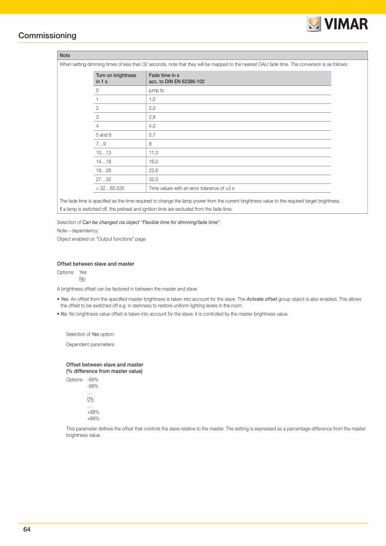
64
Note
When setting dimming times of less than 32 seconds, note that they will be mapped to the nearest DALI fade time. The conversion is as follows:
Turn on brightnessin 1 s
Fade time in sacc. to DIN EN 62386-102
0 jump to
1 1,0
2 2,0
3 2,8
4 4,0
5 and 6 5,7
7…9 8
10…13 11,3
14…18 16,0
19…26 22,6
27…32 32,0
> 32…65.535 Time values with an error tolerance of ±3 s
The fade time is specified as the time required to change the lamp power from the current brightness value to the required target brightness.
If a lamp is switched off, the preheat and ignition time are excluded from the fade time.
Selection of Can be changed via object "Flexible time for dimming/fade time":
Note – dependency:
Object enabled on "Output functions" page
Offset between slave and master
Options: Yes No
A brightness offset can be factored in between the master and slave.
• Yes: An offset from the specified master brightness is taken into account for the slave. The Activate offset group object is also enabled. This allows the offset to be switched off e.g. in darkness to restore uniform lighting levels in the room.
• No: No brightness value offset is taken into account for the slave; it is controlled by the master brightness value.
Selection of Yes option:
Dependent parameters:
Offset between slave and master(% difference from master value)
Options: -99% -98% … 0% … +98% +99%
This parameter defines the offset that controls the slave relative to the master. The setting is expressed as a percentage difference from the master brightness value.
Commissioning
65
Evaluate Group object"Activate Slave offset"Enable object on "Output functions"
Options: No Yes
• No: The Slave offset function is always active.
• Yes: The Slave offset function can be activated/deactivated via the group object for the output. This means that e.g. in darkness the offset can be switched off so that the master and slave are the same brightness. The Activate Slave offset group object must be enabled in the A Output: Functions (Turn off brightness/Burn-in/Slave offset/Partial failure) parameter window, p. 37. The reaction of the slave offset on KNX recovery and after a download is also parametrized in this window.
Note
To use the Slave offset function you first need to enable the output's Activate Slave offset group object in the A Output Functions parameter window. You also need to select the function for group x. Group x is enabled in the Group x Slave parameter window for the group in question. The Activate Slave offset information affects all groups on the output. Depending on the parametrization, the group decides whether to respond to the Activate Slave offset group object.
With active additional function.Reaction on...
...Switch on
Options: No reaction Function switches to standby
When the Slave function is activated, this parameter defines the reaction to an ON telegram on the Switch group object..
• No reaction: An ON telegram on the Switch group object is ignored.
• Function switches to standby: An ON telegram on the Switch group object puts slave mode in standby. The group executes the Brightness value telegram via the Brightness value group object. The Slave function is latent and waits for reactivation via the Activate fct Slave group object or via an ON telegram on the Switch group object.
Note
The reaction to an OFF telegram on the Switch group object cannot be parametrized.
An OFF telegram always interrupts the Slave function. The Slave function switches to standby mode, in which the brightness values on the Brightness value of Slave group object are ignored.
The Slave function is reactivated when an ON telegram is received on the Switch group object.
The reaction to a telegram with the value 1 received on the Activate fct Slave group object can be parametrized (see A Slave template (group x/ballast x) parameter window, p. 62.)
...Brightness value
Options: No reaction Function switches to standby
When the Slave function is activated, this parameter defines the reaction to a Brightness value telegram on the Brightness value group object.
• No reaction: A Brightness value telegram is ignored.
• Function switches to standby: A Brightness value telegram ends the Slave function; the group executes the telegram via the Brightness value group object. The Slave function switches to standby and waits for reactivation via the Activate fct Slave group object or via an ON telegram on the Switch group object.
...Relative dimming
Options: No reaction Function switches to standby
When the Slave function is activated, this parameter can be used to define the reaction to dimming telegram to the group object Relative dimming.
• No reaction: A Dim telegram is ignored.
• Function switches to standby: A Dim telegram ends the Slave function; the group executes the telegram. The Slave function switches to standby and waits for reactivation via the Activate fct Slave group object or via an ON telegram on the Switch group object.
Commissioning
66
...Recall scene
Options: No reaction Function switches to standby
When the Slave function is activated, this parameter defines the reaction to a scene recall.
• No reaction: A scene recall is ignored.
• Function switches to standby: A scene recall ends the Slave function; the group executes the recall. The Slave function switches to standby and waits for reactivation via the Activate fct Slave group object or via an ON telegram on the Switch group object.
Reaction on KNX bus voltage recoveryand download
Options: Not activated Activated and in standby Activate and ON State before failure
This parameter defines the state of the Slave function after a KNX bus voltage recovery or a download.
The Slave function can be parametrized with the following states:
• Not activated: The Slave function is not activated after KNX bus voltage recovery. The group reacts like a normal group without an additional function.
• Activated and in standby: The Slave function is activated after a download or KNX bus voltage recovery and is in standby. The group can be reacti-vated by an ON telegram or via the Activate fct Slave group object.
• Activate and ON: After a download or KNX bus voltage recovery, the Slave function is activated, i.e. it immediately responds to the master.
• State before failure: The Slave function retains the operating state (standby or not active) that it had before download or KNX bus voltage recovery.
Reaction on activation via object"Activate fct Slave"
Options: Activated and in standby Activate and ON
This parameter defines the state of the Slave function after it has been activated by the Activate fct Slave group object.
• Activated and in standby: The Slave function switches to standby when activated via the Activate fct Slave group object. In other words the slave does not respond direct to the master. It responds to the master if it receives an ON command via the Switch group object.
• Activate and ON: The Slave function switches on immediately when activated via the Activate fct Slave group object. In other words the slave im-mediately responds to the master.
Send status via object"Activate fct Slave/Status"
Options: No Yes
Linked group object: Activate fct Slave/Status
• No: The status of the Activate Slave function is not transmitted on the KNX.
• Yes: The Activate fct Slave/Status group object does not just activate or deactivate the Slave function. It also transmits the activation status on the KNX.
Selection of Yes option:
Dependent parameters:
Send object value
Options: On change On request After a change or on request
• On change: The status is sent when a change occurs.
• On request: The status is sent when a request occurs.
• After a change or on request: The status is sent when either a change or request occurs.
Commissioning
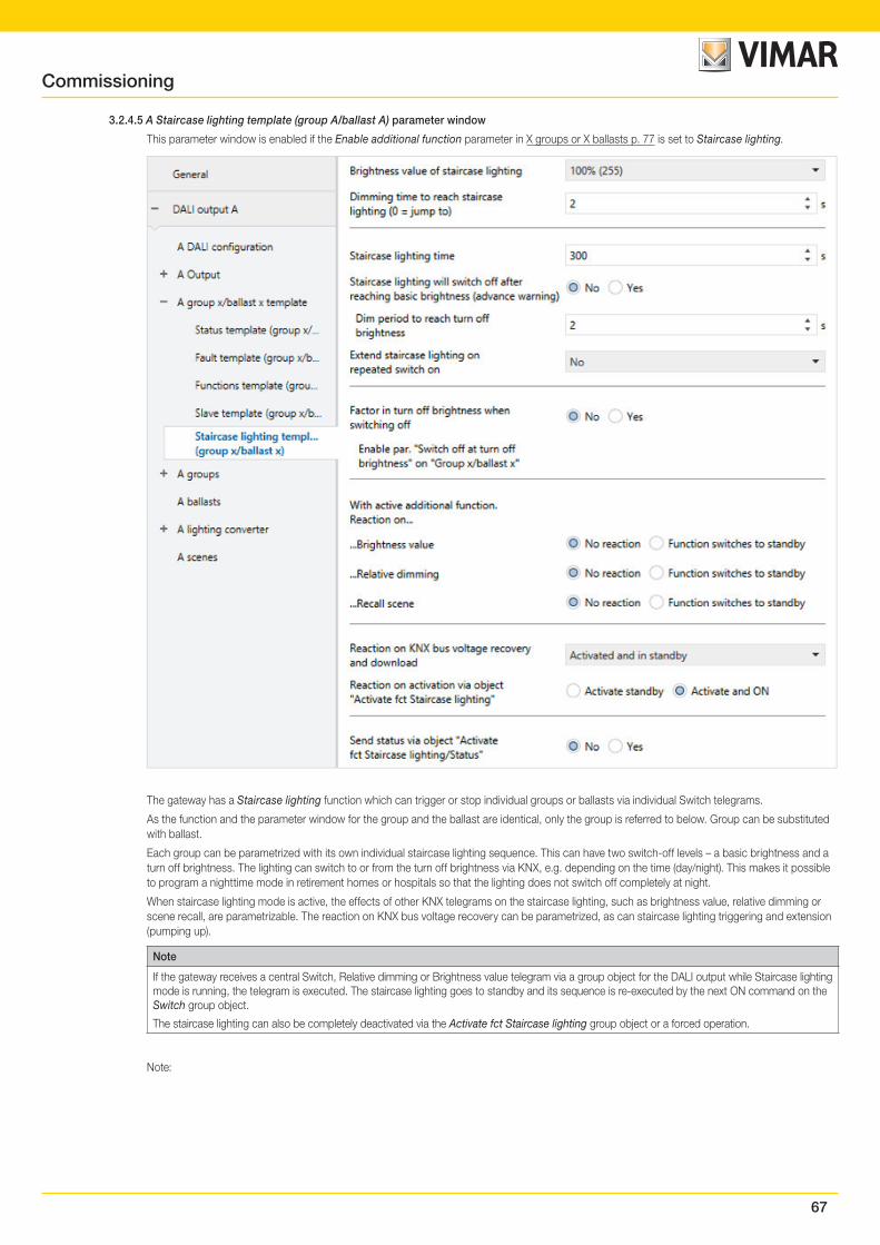
67
3.2.4.5 A Staircase lighting template (group A/ballast A) parameter window
This parameter window is enabled if the Enable additional function parameter in X groups or X ballasts p. 77 is set to Staircase lighting.
The gateway has a Staircase lighting function which can trigger or stop individual groups or ballasts via individual Switch telegrams.
As the function and the parameter window for the group and the ballast are identical, only the group is referred to below. Group can be substituted with ballast.
Each group can be parametrized with its own individual staircase lighting sequence. This can have two switch-off levels – a basic brightness and a turn off brightness. The lighting can switch to or from the turn off brightness via KNX, e.g. depending on the time (day/night). This makes it possible to program a nighttime mode in retirement homes or hospitals so that the lighting does not switch off completely at night.
When staircase lighting mode is active, the effects of other KNX telegrams on the staircase lighting, such as brightness value, relative dimming or scene recall, are parametrizable. The reaction on KNX bus voltage recovery can be parametrized, as can staircase lighting triggering and extension (pumping up).
Note
If the gateway receives a central Switch, Relative dimming or Brightness value telegram via a group object for the DALI output while Staircase lighting mode is running, the telegram is executed. The staircase lighting goes to standby and its sequence is re-executed by the next ON command on the Switch group object.
The staircase lighting can also be completely deactivated via the Activate fct Staircase lighting group object or a forced operation.
Note:
Commissioning
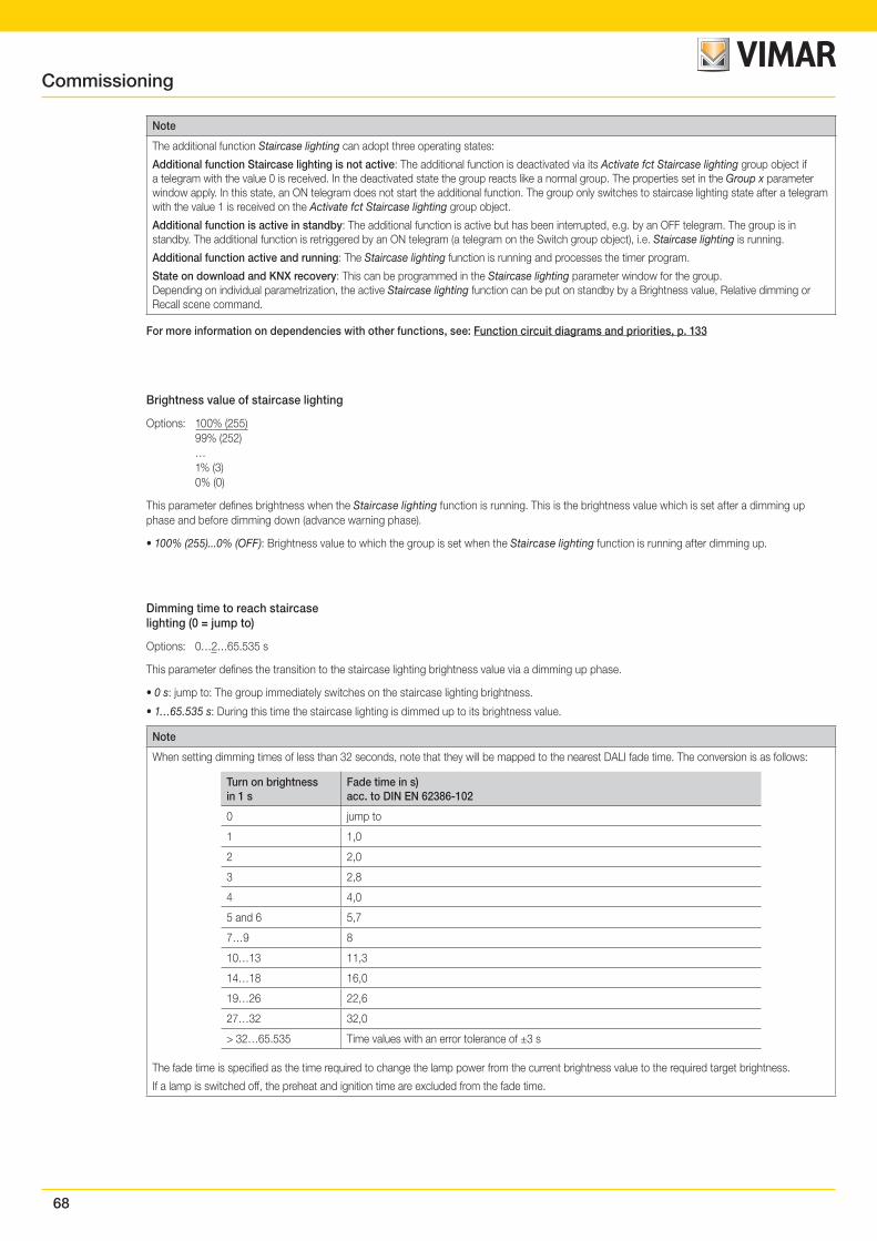
68
Note
The additional function Staircase lighting can adopt three operating states:
Additional function Staircase lighting is not active: The additional function is deactivated via its Activate fct Staircase lighting group object if a telegram with the value 0 is received. In the deactivated state the group reacts like a normal group. The properties set in the Group x parameter window apply. In this state, an ON telegram does not start the additional function. The group only switches to staircase lighting state after a telegram with the value 1 is received on the Activate fct Staircase lighting group object.
Additional function is active in standby: The additional function is active but has been interrupted, e.g. by an OFF telegram. The group is in standby. The additional function is retriggered by an ON telegram (a telegram on the Switch group object), i.e. Staircase lighting is running.
Additional function active and running: The Staircase lighting function is running and processes the timer program.
State on download and KNX recovery: This can be programmed in the Staircase lighting parameter window for the group.Depending on individual parametrization, the active Staircase lighting function can be put on standby by a Brightness value, Relative dimming or Recall scene command.
For more information on dependencies with other functions, see: Function circuit diagrams and priorities, p. 133
Brightness value of staircase lighting
Options: 100% (255) 99% (252) … 1% (3) 0% (0)
This parameter defines brightness when the Staircase lighting function is running. This is the brightness value which is set after a dimming up phase and before dimming down (advance warning phase).
• 100% (255)...0% (OFF): Brightness value to which the group is set when the Staircase lighting function is running after dimming up.
Dimming time to reach staircaselighting (0 = jump to)
Options: 0…2…65.535 s
This parameter defines the transition to the staircase lighting brightness value via a dimming up phase.
• 0 s: jump to: The group immediately switches on the staircase lighting brightness.
• 1…65.535 s: During this time the staircase lighting is dimmed up to its brightness value.
Note
When setting dimming times of less than 32 seconds, note that they will be mapped to the nearest DALI fade time. The conversion is as follows:
Turn on brightnessin 1 s
Fade time in s)acc. to DIN EN 62386-102
0 jump to
1 1,0
2 2,0
3 2,8
4 4,0
5 and 6 5,7
7…9 8
10…13 11,3
14…18 16,0
19…26 22,6
27…32 32,0
> 32…65.535 Time values with an error tolerance of ±3 s
The fade time is specified as the time required to change the lamp power from the current brightness value to the required target brightness.
If a lamp is switched off, the preheat and ignition time are excluded from the fade time.
Commissioning
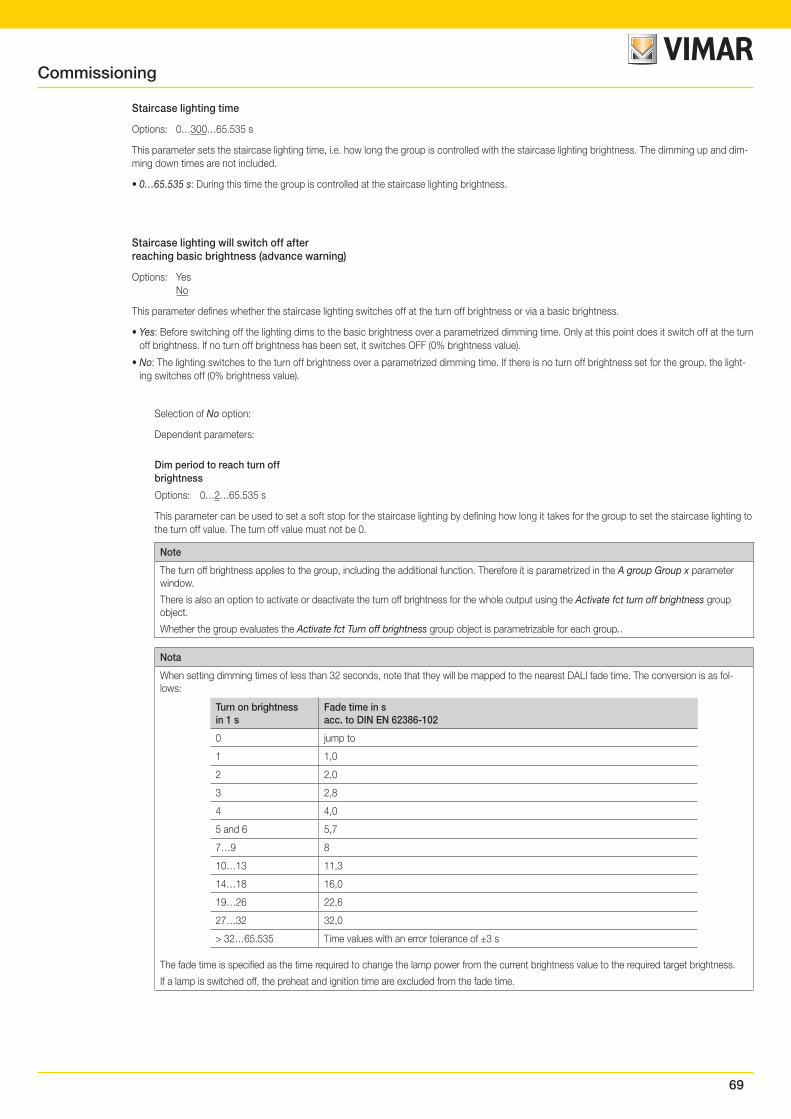
69
Staircase lighting time
Options: 0…300…65.535 s
This parameter sets the staircase lighting time, i.e. how long the group is controlled with the staircase lighting brightness. The dimming up and dim-ming down times are not included.
• 0…65.535 s: During this time the group is controlled at the staircase lighting brightness.
Staircase lighting will switch off afterreaching basic brightness (advance warning)
Options: Yes No
This parameter defines whether the staircase lighting switches off at the turn off brightness or via a basic brightness.
• Yes: Before switching off the lighting dims to the basic brightness over a parametrized dimming time. Only at this point does it switch off at the turn off brightness. If no turn off brightness has been set, it switches OFF (0% brightness value).
• No: The lighting switches to the turn off brightness over a parametrized dimming time. If there is no turn off brightness set for the group, the light-ing switches off (0% brightness value).
Selection of No option:
Dependent parameters:
Dim period to reach turn offbrightness
Options: 0…2…65.535 s
This parameter can be used to set a soft stop for the staircase lighting by defining how long it takes for the group to set the staircase lighting to the turn off value. The turn off value must not be 0.
Note
The turn off brightness applies to the group, including the additional function. Therefore it is parametrized in the A group Group x parameter window.
There is also an option to activate or deactivate the turn off brightness for the whole output using the Activate fct turn off brightness group object.
Whether the group evaluates the Activate fct Turn off brightness group object is parametrizable for each group..
Nota
When setting dimming times of less than 32 seconds, note that they will be mapped to the nearest DALI fade time. The conversion is as fol-lows:
Turn on brightnessin 1 s
Fade time in sacc. to DIN EN 62386-102
0 jump to
1 1,0
2 2,0
3 2,8
4 4,0
5 and 6 5,7
7…9 8
10…13 11,3
14…18 16,0
19…26 22,6
27…32 32,0
> 32…65.535 Time values with an error tolerance of ±3 s
The fade time is specified as the time required to change the lamp power from the current brightness value to the required target brightness.
If a lamp is switched off, the preheat and ignition time are excluded from the fade time.
Commissioning
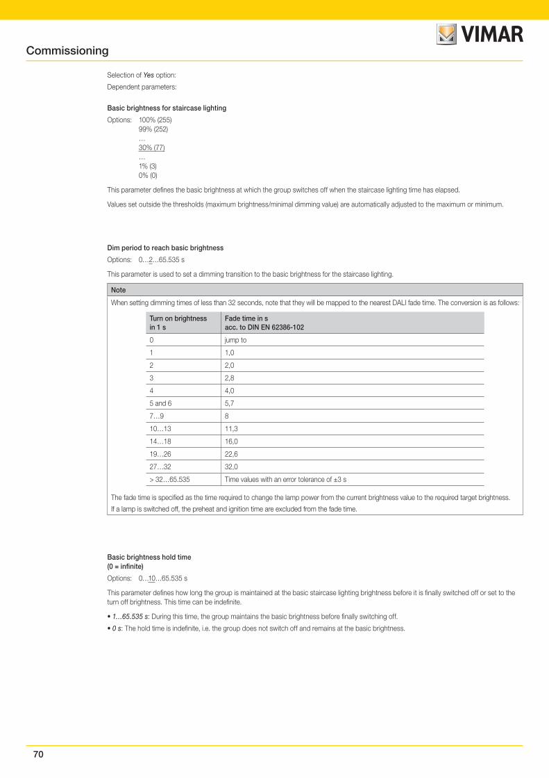
70
Selection of Yes option:
Dependent parameters:
Basic brightness for staircase lighting
Options: 100% (255) 99% (252) … 30% (77) … 1% (3) 0% (0)
This parameter defines the basic brightness at which the group switches off when the staircase lighting time has elapsed.
Values set outside the thresholds (maximum brightness/minimal dimming value) are automatically adjusted to the maximum or minimum.
Dim period to reach basic brightness
Options: 0…2…65.535 s
This parameter is used to set a dimming transition to the basic brightness for the staircase lighting.
Note
When setting dimming times of less than 32 seconds, note that they will be mapped to the nearest DALI fade time. The conversion is as follows:
Turn on brightnessin 1 s
Fade time in sacc. to DIN EN 62386-102
0 jump to
1 1,0
2 2,0
3 2,8
4 4,0
5 and 6 5,7
7…9 8
10…13 11,3
14…18 16,0
19…26 22,6
27…32 32,0
> 32…65.535 Time values with an error tolerance of ±3 s
The fade time is specified as the time required to change the lamp power from the current brightness value to the required target brightness.
If a lamp is switched off, the preheat and ignition time are excluded from the fade time.
Basic brightness hold time(0 = infinite)
Options: 0…10…65.535 s
This parameter defines how long the group is maintained at the basic staircase lighting brightness before it is finally switched off or set to the turn off brightness. This time can be indefinite.
• 1…65.535 s: During this time, the group maintains the basic brightness before finally switching off.
• 0 s: The hold time is indefinite, i.e. the group does not switch off and remains at the basic brightness.
Commissioning
71
Extend staircase lighting onrepeated switch on
Options: No Yes - restart staircase lighting time (retrigger) Yes - Extend staircase lighting time up to max 2 x (pumping up) Yes - Extend staircase lighting time up to max 3 x (pumping up) Yes - Extend staircase lighting time up to max 4 x (pumping up) Yes - Extend staircase lighting time up to max 5 x (pumping up)
If a further ON telegram is received via the Switch object during the staircase lighting sequence (including dimming down/advance warning), the remaining staircase lighting time can be extended. This is possible by repeated operation of the push button (“pumping up“) until the maximum parametrized number of retriggering operations is reached. The maximum time can be set to 1, 2, 3, 4 or 5 times the staircase lighting time.
Let's say the staircase lighting time has been extended to the maximum time by pumping up. If some of the time has already elapsed, the staircase lighting time can be extended to the maximum time again by pumping up.
However, the parametrized maximum time may not be exceeded.
• No: Incoming ON telegrams are ignored. The staircase lighting time continues unmodified to completion.
• Yes - restart staircase lighting time (retrigger): The staircase light time is reset with each new ON telegram and starts to count again. This option allows the process to be repeated as often as desired.
• Yes - Extend staircase lighting time up to max 2/3/4/5 x (pumping up): New ON telegrams extend the staircase lighting time by 2/3/4/5 times.
Factor in turn off brightness whenswitching offEnable par. "Switch off at turn offbrightness" on "Group x/ballast x"
Options: Yes No
Turn off brightness can be activated/deactivated via the KNX using the Activate fct Turn off brightness group object. This means a timer can be used, for example, to set the lighting to a parametrizable turn off brightness at night instead of switching it off.
• Yes: The ballast, group or output evaluates the Activate fct Turn off brightness group object. If the gateway receives a telegram via this group object on the output, the system reacts as follows:
1: The turn off brightness is set to the parametrized brightness value. The Turn off brightness function is activated. An OFF command will then apply this brightness value instead of OFF, 0%
0: The Turn off brightness function is not activated and an OFF command switches the system off via the Switch group object, applying a bright-ness value of OFF, 0%.
• No: The ballast, group or output does not evaluate the Activate fct Turn off brightness group object. The system always switches off at the para-metrized turn off brightness.
For more information see group object Activate fct Turn off brightness/Status.
Note
The Turn off brightness function can be applied to the whole DALI output, all ballasts and all groups. It must first be enabled in the A Output functions parameter window along with Activate fct Turn off brightness group object.
To define whether a ballast or a group reacts to the output's Turn off brightness function, make the settings in the relevant Ballast x or Group x parameter window.
Commissioning
72
With active additional function.Reaction on...
...Brightness value
Options: No reaction Function switches to standby
When the Staircase lighting function is activated, this parameter defines the reaction to a Brightness value telegram on the Brightness value group object.
• No reaction: A Brightness value telegram is ignored.
• Function switches to standby: A Brightness value telegram ends the Staircase lighting function; the group executes the telegram via the Bright-ness value group object. The Staircase lighting function switches to standby and waits for reactivation via the Activate fct Staircase lighting group object or via an ON telegram on the Switch group object.
...Relative dimming
Options: No reaction Function switches to standby
When the Staircase lighting function is activated, this parameter determines the reaction to a Dim telegram on the Relative dimming group object.
• No reaction: A Dim telegram is ignored.
• Function switches to standby: A Dim telegram ends the Staircase lighting function; the group executes the telegram. The Staircase lighting function switches to standby and waits for reactivation via the Activate fct Staircase lighting group object via an ON telegram on the Switch group object.
...Recall scene
Options: No reaction Function switches to standby
When the Slave function is activated, this parameter defines the reaction to a scene recall.
• No reaction: A scene recall is ignored.
• Function switches to standby: A scene recall ends the Staircase lighting function; the group executes the recall. The Staircase lighting function switches to standby and waits for reactivation via the Activate fct Staircase lighting group object or via an ON telegram on the Switch group object.
Reaction on KNX bus voltage recoveryand download
Options: Not activated Activated and in standby Activate and ON State before failure
This parameter defines the state of the Staircase lighting function after a KNX bus voltage recovery or a download.
The Staircase lighting function can be parametrized with the following states:
• Not activated: The Staircase lighting function is not activated after KNX bus voltage recovery. The group reacts like a normal group without an additional function.
• Activated and in standby: The Staircase lighting function is activated after a download or KNX bus voltage recovery and is in standby. The group can be reactivated by an ON telegram or via the Activate fct Staircase lighting group object.
• Activate and ON: The Staircase lighting function is activated and started after a download or after KNX bus voltage recovery, i.e. the staircase lighting starts the time sequence.
• State before failure: The Staircase lighting function retains the operating state (standby or not active) that it had before download or KNX bus voltage recovery.
Commissioning
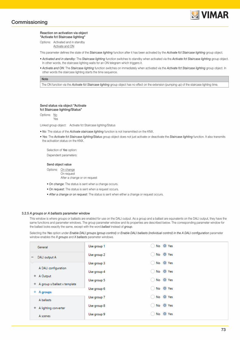
73
Reaction on activation via object"Activate fct Staircase lighting"
Options: Activated and in standby Activate and ON
This parameter defines the state of the Staircase lighting function after it has been activated by the Activate fct Staircase lighting group object.
• Activated and in standby: The Staircase lighting function switches to standby when activated via the Activate fct Staircase lighting group object. In other words, the staircase lighting waits for an ON telegram which triggers it.
• Activate and ON: The Staircase lighting function switches on immediately when activated via the Activate fct Staircase lighting group object. In other words the staircase lighting starts the time sequence.
Note
The ON function via the Activate fct Staircase lighting group object has no effect on the extension (pumping up) of the staircase lighting time.
Send status via object "Activatefct Staircase lighting/Status"
Options: No Yes
Linked group object: Activate fct Staircase lighting/Status
• No: The status of the Activate staircase lighting function is not transmitted on the KNX.
• Yes: The Activate fct Staircase lighting/Status group object does not just activate or deactivate the Staircase lighting function. It also transmits the activation status on the KNX.
Selection of Yes option:
Dependent parameters:
Send object value
Options: On change On request After a change or on request
• On change: The status is sent when a change occurs.
• On request: The status is sent when a request occurs.
• After a change or on request: The status is sent when either a change or request occurs.
3.2.5 A groups or A ballasts parameter window
This window is where groups or ballasts are enabled for use on the DALI output. As a group and a ballast are equivalents on the DALI output, they have the same functions and parameter windows. The group parameter window and its properties are described below. The corresponding parameter window for the ballast looks exactly the same, except with the word ballast instead of group.
Selecting the Yes option under Enable DALI groups (group control) or Enable DALI ballasts (individual control) in the A DALI configuration parameter window enables the X groups and X ballasts parameter windows.
Commissioning
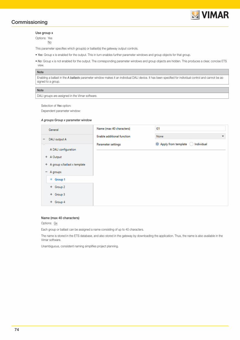
74
Use group x
Options: Yes No
This parameter specifies which group(s) or ballast(s) the gateway output controls.
• Yes: Group x is enabled for the output. This in turn enables further parameter windows and group objects for that group.
• No: Group x is not enabled for the output. The corresponding parameter windows and group objects are hidden. This produces a clear, concise ETS view.
Note
Enabling a ballast in the A ballasts parameter window makes it an individual DALI device. It has been specified for individual control and cannot be as-signed to a group.
Note
DALI groups are assigned in the Vimar software.
Selection of Yes option:
Dependent parameter window:
A groups Group x parameter window
Name (max 40 characters)
Options: Gx
Each group or ballast can be assigned a name consisting of up to 40 characters.
The name is stored in the ETS database, and also stored in the gateway by downloading the application. Thus, the name is also available in the Vimar software.
Unambiguous, consistent naming simplifies project planning.
Commissioning
75
Enable additional function
Options: None Slave Staircase lighting
Linked group object: Activate fct Slave Activate fct Staircase lighting
This parameter defines an additional function for the group or ballast. At the same time, it enables a corresponding parameter window where the additional function can be parametrized.
• None: This group/ballast operates as "normal", without an additional function.
• Slave: This group/ballast is defined as a slave. The slave is forcibly controlled by a master. The Group x Slave parameter window is enabled. This is where the properties of the slave are parametrized. The slave receives the required brightness value from a master ballast or group via the Brightness value of slave group object or internally via the gateway itself.
• Staircase lighting: When the Staircase lighting function is activated, the group/ballast is switched on, and after a defined time it is automati-cally switched off or dimmed down slowly as an advance warning. The staircase lighting function has two levels. The turn off brightness can be activated/deactivated via the KNX for nighttime operation.
Note
The additional functions Slave and Staircase lighting can adopt three operating states:
Additional function is not active: The additional function has been deactivated via a telegram with value 0 received on the function's Enable ad-ditional function group object. In this state, the group/ballast behaves normally. Accordingly, the group or ballast settings apply.In this state, an ON telegram does not start the additional function. The additional function can only be started after a telegram with the value 1 has been received on the Enable additional function group object.
Additional function is in standby: The additional function is active but has been interrupted, e.g. by an OFF telegram. The group/ballast is in standby. An ON telegram (telegram on the Switch group object) retriggers the additional function, i.e. the staircase lighting runs and the slave starts responding to the Brightness value of slave group object or internally to its master group or ballast again..
Additional function running: Staircase lighting runs; the Slave function receives brightness values from the master. With corresponding parametri-zation of the switching telegrams, the additional functions can be set to standby mode.
State on download and KNX recovery: This can be programmed in the Slave or Staircase lighting parameter window for the group/ballast.When the corresponding group object for the status message of the additional function is enabled via the settings, the status of the additional func-tion (activated/deactivated) is sent via the respective Activate additional function/Status group object.
Parameter settings
Options: Individual Apply from template
This parameter defines whether the group/ballast settings are taken from the template or individually set.
• Individual: The group/ballast is individually parametrized. Corresponding parameters for the group/ballast are shown. The content of the indi-vidual parameters is the same as that in the template parameters.
• Apply from template: The group/ballast takes its parameters from the template.
Note
The advantages of using the template for parametrization are:
• A clearly organized, compact ETS parameter interface (one template parameter window rather than 64 individual ones)
• All groups and ballasts react in the same way (the same properties apply to all groups/ballasts, e.g. dimming thresholds)
• Fast parameter changes (changes need only be made in the template rather than 64 times, for each ballast)
The individual parameter windows and parameters are identical to those in the templates, therefore the individual parameters are not covered sepa-rately here – please see A template group x/ballast x parameter window, p. 43.
Commissioning
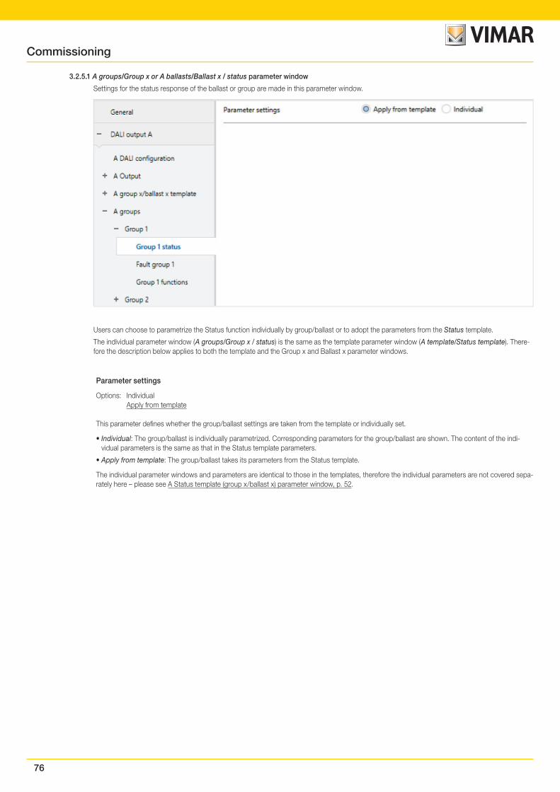
76
3.2.5.1 A groups/Group x or A ballasts/Ballast x / status parameter window
Settings for the status response of the ballast or group are made in this parameter window.
Users can choose to parametrize the Status function individually by group/ballast or to adopt the parameters from the Status template.
The individual parameter window (A groups/Group x / status) is the same as the template parameter window (A template/Status template). There-fore the description below applies to both the template and the Group x and Ballast x parameter windows.
Parameter settings
Options: Individual Apply from template
This parameter defines whether the group/ballast settings are taken from the template or individually set.
• Individual: The group/ballast is individually parametrized. Corresponding parameters for the group/ballast are shown. The content of the indi-vidual parameters is the same as that in the Status template parameters.
• Apply from template: The group/ballast takes its parameters from the Status template.
The individual parameter windows and parameters are identical to those in the templates, therefore the individual parameters are not covered sepa-rately here – please see A Status template (group x/ballast x) parameter window, p. 52.
Commissioning
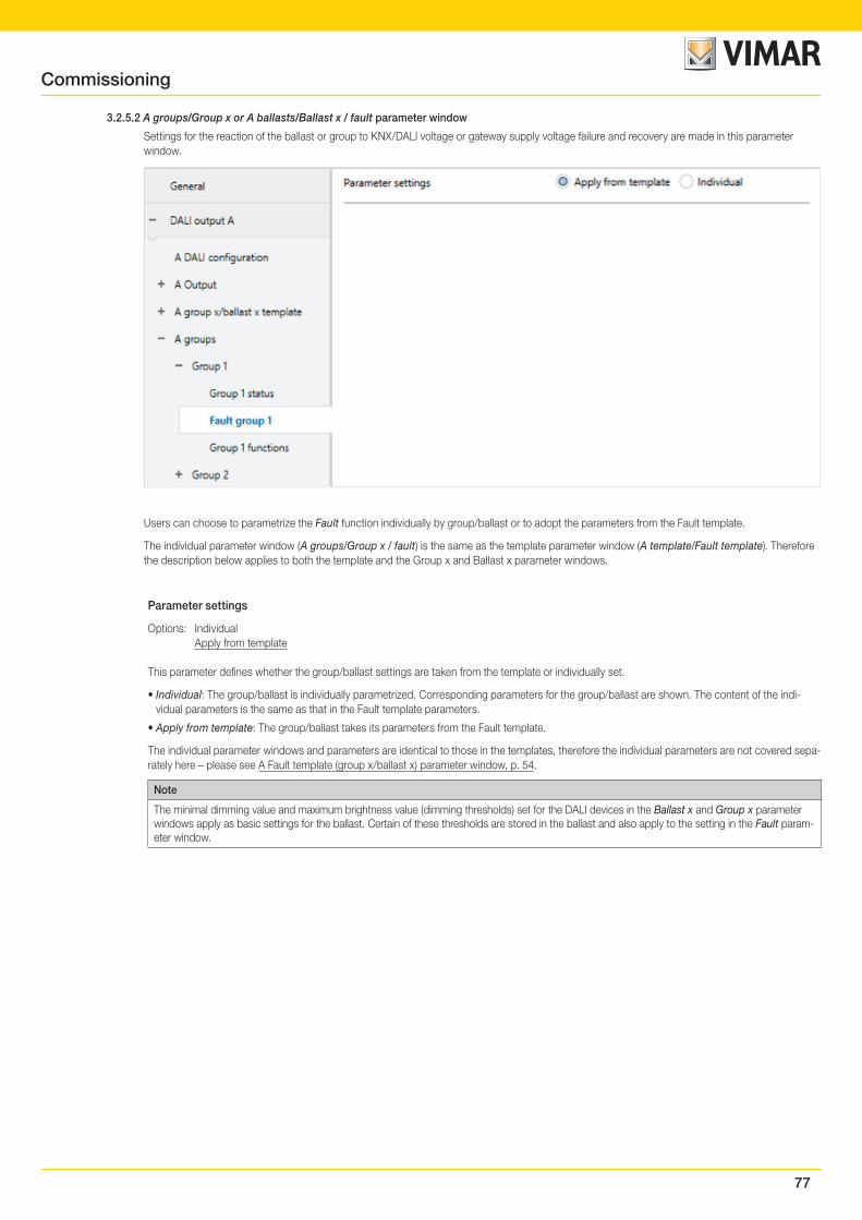
77
3.2.5.2 A groups/Group x or A ballasts/Ballast x / fault parameter window
Settings for the reaction of the ballast or group to KNX/DALI voltage or gateway supply voltage failure and recovery are made in this parameter window.
Users can choose to parametrize the Fault function individually by group/ballast or to adopt the parameters from the Fault template.
The individual parameter window (A groups/Group x / fault) is the same as the template parameter window (A template/Fault template). Therefore the description below applies to both the template and the Group x and Ballast x parameter windows.
Parameter settings
Options: Individual Apply from template
This parameter defines whether the group/ballast settings are taken from the template or individually set.
• Individual: The group/ballast is individually parametrized. Corresponding parameters for the group/ballast are shown. The content of the indi-vidual parameters is the same as that in the Fault template parameters.
• Apply from template: The group/ballast takes its parameters from the Fault template.
The individual parameter windows and parameters are identical to those in the templates, therefore the individual parameters are not covered sepa-rately here – please see A Fault template (group x/ballast x) parameter window, p. 54.
Note
The minimal dimming value and maximum brightness value (dimming thresholds) set for the DALI devices in the Ballast x and Group x parameter windows apply as basic settings for the ballast. Certain of these thresholds are stored in the ballast and also apply to the setting in the Fault param-eter window.
Commissioning
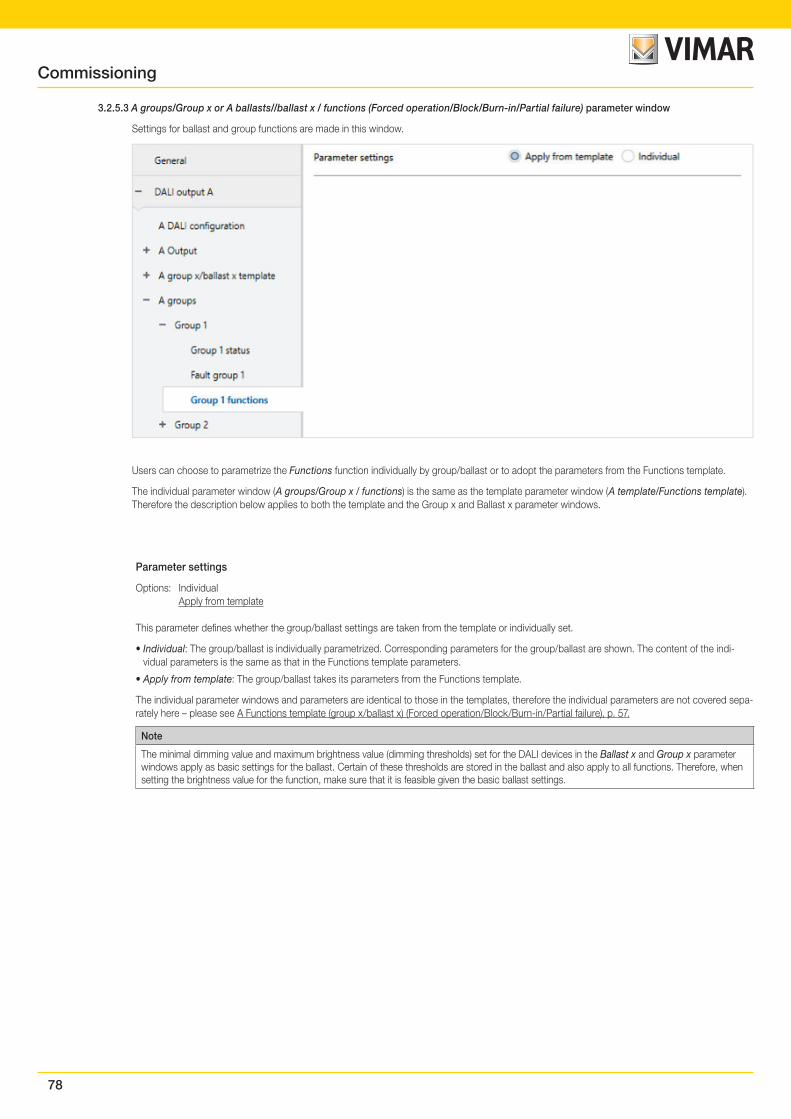
78
3.2.5.3 A groups/Group x or A ballasts//ballast x / functions (Forced operation/Block/Burn-in/Partial failure) parameter window
Settings for ballast and group functions are made in this window.
Users can choose to parametrize the Functions function individually by group/ballast or to adopt the parameters from the Functions template.
The individual parameter window (A groups/Group x / functions) is the same as the template parameter window (A template/Functions template). Therefore the description below applies to both the template and the Group x and Ballast x parameter windows.
Parameter settings
Options: Individual Apply from template
This parameter defines whether the group/ballast settings are taken from the template or individually set.
• Individual: The group/ballast is individually parametrized. Corresponding parameters for the group/ballast are shown. The content of the indi-vidual parameters is the same as that in the Functions template parameters.
• Apply from template: The group/ballast takes its parameters from the Functions template.
The individual parameter windows and parameters are identical to those in the templates, therefore the individual parameters are not covered sepa-rately here – please see A Functions template (group x/ballast x) (Forced operation/Block/Burn-in/Partial failure), p. 57.
Note
The minimal dimming value and maximum brightness value (dimming thresholds) set for the DALI devices in the Ballast x and Group x parameter windows apply as basic settings for the ballast. Certain of these thresholds are stored in the ballast and also apply to all functions. Therefore, when setting the brightness value for the function, make sure that it is feasible given the basic ballast settings.
Commissioning
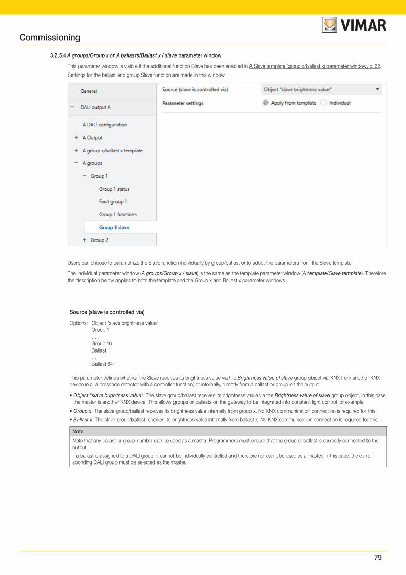
79
3.2.5.4 A groups/Group x or A ballasts/Ballast x / slave parameter window
This parameter window is visible if the additional function Slave has been enabled in A Slave template (group x/ballast x) parameter window, p. 62.
Settings for the ballast and group Slave function are made in this window.
Users can choose to parametrize the Slave function individually by group/ballast or to adopt the parameters from the Slave template.
The individual parameter window (A groups/Group x / slave) is the same as the template parameter window (A template/Slave template). Therefore the description below applies to both the template and the Group x and Ballast x parameter windows.
Source (slave is controlled via)
Options: Object "slave brightness value" Group 1 … Group 16 Ballast 1 … Ballast 64
This parameter defines whether the Slave receives its brightness value via the Brightness value of slave group object via KNX from another KNX device (e.g. a presence detector with a controller function) or internally, directly from a ballast or group on the output.
• Object "slave brightness value“: The slave group/ballast receives its brightness value via the Brightness value of slave group object. In this case, the master is another KNX device. This allows groups or ballasts on the gateway to be integrated into constant light control for example.
• Group x: The slave group/ballast receives its brightness value internally from group x. No KNX communication connection is required for this.
• Ballast x: The slave group/ballast receives its brightness value internally from ballast x. No KNX communication connection is required for this.
Note
Note that any ballast or group number can be used as a master. Programmers must ensure that the group or ballast is correctly connected to the output.
If a ballast is assigned to a DALI group, it cannot be individually controlled and therefore nor can it be used as a master. In this case, the corre-sponding DALI group must be selected as the master.
Commissioning
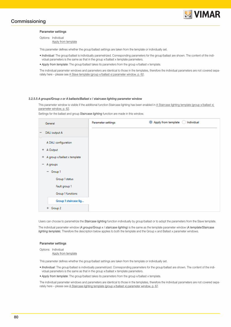
80
Parameter settings
Options: Individual Apply from template
This parameter defines whether the group/ballast settings are taken from the template or individually set.
• Individual: The group/ballast is individually parametrized. Corresponding parameters for the group/ballast are shown. The content of the indi-vidual parameters is the same as that in the group x/ballast x template parameters.
• Apply from template: The group/ballast takes its parameters from the group x/ballast x template.
The individual parameter windows and parameters are identical to those in the templates, therefore the individual parameters are not covered sepa-rately here – please see A Slave template (group x/ballast x) parameter window, p. 62.
3.2.5.5 A groups/Group x or A ballasts/Ballast x / staircase lighting parameter window
This parameter window is visible if the additional function Staircase lighting has been enabled in A Staircase lighting template (group x/ballast x) parameter window, p. 62.
Settings for the ballast and group Staircase lighting function are made in this window.
Users can choose to parametrize the Staircase lighting function individually by group/ballast or to adopt the parameters from the Slave template.
The individual parameter window (A groups/Group x / staircase lighting) is the same as the template parameter window (A template/Staircase lighting template). Therefore the description below applies to both the template and the Group x and Ballast x parameter windows.
Parameter settings
Options: Individual Apply from template
This parameter defines whether the group/ballast settings are taken from the template or individually set.
• IIndividual: The group/ballast is individually parametrized. Corresponding parameters for the group/ballast are shown. The content of the indi-vidual parameters is the same as that in the group x/ballast x template parameters.
• Apply from template: The group/ballast takes its parameters from the group x/ballast x template.
The individual parameter windows and parameters are identical to those in the templates, therefore the individual parameters are not covered sepa-rately here – please see A Staircase lighting template (group x/ballast x) parameter window, p. 67.
Commissioning
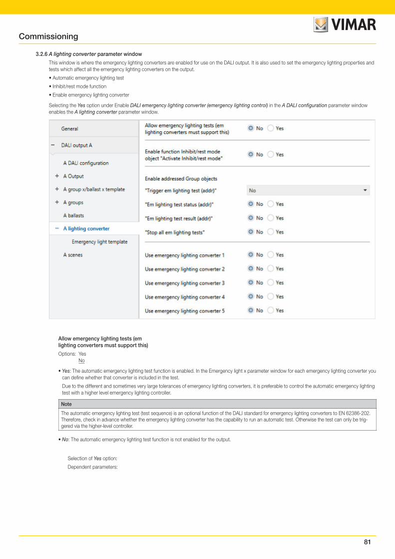
81
3.2.6 A lighting converter parameter window
This window is where the emergency lighting converters are enabled for use on the DALI output. It is also used to set the emergency lighting properties and tests which affect all the emergency lighting converters on the output.
• Automatic emergency lighting test
• Inhibit/rest mode function
• Enable emergency lighting converter
Selecting the Yes option under Enable DALI emergency lighting converter (emergency lighting control) in the A DALI configuration parameter window enables the A lighting converter parameter window.
Allow emergency lighting tests (emlighting converters must support this)
Options: Yes No
• Yes: The automatic emergency lighting test function is enabled. In the Emergency light x parameter window for each emergency lighting converter you can define whether that converter is included in the test.
Due to the different and sometimes very large tolerances of emergency lighting converters, it is preferable to control the automatic emergency lighting test with a higher level emergency lighting controller.
Note
The automatic emergency lighting test (test sequence) is an optional function of the DALI standard for emergency lighting converters to EN 62386-202. Therefore, check in advance whether the emergency lighting converter has the capability to run an automatic test. Otherwise the test can only be trig-gered via the higher-level controller.
• No: The automatic emergency lighting test function is not enabled for the output.
Selection of Yes option:
Dependent parameters:
Commissioning
82
Offset time betweentesting two consecutiveemergency lighting converters
Options: 0…1…255 x 15 min
This parameter defines an offset at 15 minute intervals between automatic test starts for two neighboring emergency lighting converters. This offset can be used to avoid a situation where all the emergency lighting converters at once are being tested or in the post-test recharging cycle.
The formula used for the offset is the DALI short address multiplied by the offset. In other words, an offset of 1 (= 15 minutes) means that converter 1 is offset by 15 minutes, converter 2 by 30 minutes, and so on.
The gateway can set this time but is not responsible for the timing tolerances that the emergency lighting converter uses to implement it. Also note that a test will not run immediately if an emergency light is in the post-test recharging cycle.
As soon as a time for automatic testing is written to the converter, it must trigger the emergency lighting test..
Enable fct Automatic emergencylighting testObject "Synch auto emergencylighting tests"
Options: Yes No
Linked group object: Synchronize auto emergency lighting tests
• Yes: The gateway sends the start request for the automatic emergency lighting test to the emergency lighting converter. The request is only sent to those converters to be included. Settings for this are made in the Emergency light x parameter window using the parameters Include in automatic function test or Include in automatic duration/partial duration test.
The automatic emergency lighting test is a standalone function on an emergency lighting converter. The converter runs the tests cyclically based on its own stipulated timing. There is no need for additional triggering via the gateway or an emergency lighting controller when auto-matic testing is active. The test result is provided by the converter in the converter, read by the gateway and sent on the KNX.
Note that there is a Pause between two DALI QUERY polls parameter in the A DALI configuration parameter window. The longer the pause selected, the later the gateway will read the test result from the converter.
• No: The automatic emergency lighting test function is not enabled.
Enable function Inhibit/rest modeobject "Activate Inhibit/rest mode"
Options: Yes No
Linked group object: Activate Inhibit/rest mode
• Yes: The Inhibit/rest mode function and the Activate Inhibit/rest mode group object on the output are enabled.
Whether or not an emergency lighting converter evaluates the group object and executes the Inhibit/rest mode function is defined in the Emer-gency light x parameter window.
This means it is possible to deactivate the emergency lighting function so as to conserve the battery charge e.g. during a construction/commis-sioning phase.
Note
Rest mode is a state in which the emergency light is switched off during its emergency lighting operation.
Inhibit mode is a timed state in which the emergency light does not switch to emergency operation in the event of a mains voltage failure.
DangerIn both cases, the emergency light no longer fulfils its safety function and remains off.
For this reason, use this function with great care. It can be helpful to use Inhibit/rest mode during the construction phase when the power supply is often switched off, to prevent the emergency lighting battery from constantly charging/discharging and thus conserve the emergency light.
• No: The Inhibit/rest mode function is not enabled for the output.
Commissioning
83
Selection of Yes option:
Dependent parameters:
Automatically exitInhibit/rest mode after
Options: 0…8…48 h
This parameter defines how long the emergency lighting converter stays in Inhibit/rest mode. There will be no emergency lighting function dur-ing this time. The emergency lighting converter does not switch on the emergency lighting in the event of a mains voltage failure.
Note
The time interval is 15 minutes. The gateway repeats the DALI Inhibit and Rest command for the emergency lighting converter approximately every 5 minutesi.
Send status Inhibit/rest mode
Options: No Yes
Linked group object: Activate emergency lighting Inhibit/rest mode/Status
• Yes: The Activate emergency lighting Inhibit/rest mode/Status group object not only activates the mode but also displays the status, i.e. whether at least one emergency lighting converter on the output is in Inhibit/rest mode. Information on individual emergency lighting convert-ers is determined by the Emergency lighting converter status group object.
• No: No Inhibit/rest mode activation status is sent on the KNX.
Enable addressed Group objects"Trigger em lighting test (addr)"
Options: No Yes, KNX format DPT_CTC Yes, 01542 format
Linked group object: Trigger em lighting test addr (CTC) Trigger em lighting test addr (01542)
• No: No addressed group object for the output is enabled to start an emergency lighting test. Regardless of this, a test can be started via the group object for the individual emergency lighting converters.
• Yes, KNX DTP_CTC format: This enables an addressed group object for the output which triggers and stops an emergency lighting test. The coding of the group object corresponds to the KNX DPT specification for interworking between KNX devices.
• Yes, DGN/S1.16.1 format: This enables an addressed group object for the output which triggers and stops an emergency lighting test. The coding for the group object corresponds to the predecessor device DGN/S1.16.1 ABB. This means that an existing KNX emergency lighting controller that has already operated with the DGN/S1.16.1 can still be used, without the need for new decoding.
"Em lighting test status (addr)"
Options: Yes No
Linked group object: Em lighting test status (addr) (4 byte)
• Yes: The Em lighting test status (addr) addressed group object for the output is enabled. This sends the status of the emergency lighting test (pending, running, finished) on the KNX.
• No: The status of the emergency lighting test is not sent on the KNX in an addressed group object for the output.
The status is sent whenever a change occurs, so no status is lost provided there is a connection between the emergency lighting converter and the gateway.
On KNX recovery the latest status values are sent if they are different from the previous ones sent.
The last status of the currently selected emergency lighting converter is sent on request.
Commissioning

84
"Em lighting test result (addr)"
Options: Yes No
Linked group object: Em lighting test result (addr) (2 byte)
• Yes: The Em lighting test status (addr) group object is enabled. This sends the test result for the emergency lighting test on the KNX.
• No: The result of the emergency lighting test is not sent for the output on the KNX.
The result is sent whenever a change occurs, so no result is lost provided there is a connection between the emergency lighting converter and the gateway.
On KNX recovery the latest results are sent if they are different from the previous ones sent.
The last result of the currently selected emergency lighting converter is sent on request.
"Stop all em lighting tests"
Options: Yes No
Linked group object: Stop all em lighting tests
• Yes: The Stop all em lighting tests group object is enabled. This object is used to stop all emergency lighting tests. Running tests are inter-rupted. Pending tests are canceled.
• No: The Stop all em lighting tests group object is not enabled.
Commissioning
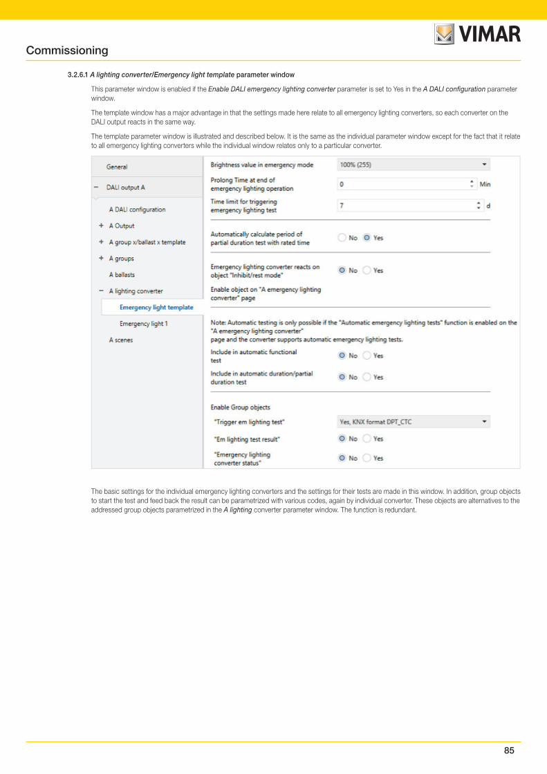
85
3.2.6.1 A lighting converter/Emergency light template parameter window
This parameter window is enabled if the Enable DALI emergency lighting converter parameter is set to Yes in the A DALI configuration parameter window.
The template window has a major advantage in that the settings made here relate to all emergency lighting converters, so each converter on the DALI output reacts in the same way.
The template parameter window is illustrated and described below. It is the same as the individual parameter window except for the fact that it relate to all emergency lighting converters while the individual window relates only to a particular converter.
The basic settings for the individual emergency lighting converters and the settings for their tests are made in this window. In addition, group objects to start the test and feed back the result can be parametrized with various codes, again by individual converter. These objects are alternatives to the addressed group objects parametrized in the A lighting converter parameter window. The function is redundant.
Commissioning
86
Brightness value in emergency mode
Options: 100% (255) 99% (252) … 1% (3)
This parameter defines the brightness value adopted in emergency mode.
The value set by this parameter is stored in the emergency lighting converter and therefore remains available even if there is no connection to the gateway.
• 100% (255)...1%: Brightness value adopted by the emergency light in the event of a mains voltage failure.This setting cannot be lower than the minimal dimming value for the emergency lighting converter, which is stored in the converter and cannot be changed by the gateway.
Note
The emergency lighting converters must support brightness value parametrization. Most converters have a fixed emergency brightness in order to ensure an emergency mode compatible with the battery and the lamp power.
For an emergency lighting converter, DALI value 255 is specified as an undefined brightness value. Therefore the maximum brightness value set-ting of 255 is mapped to DALI 254.
Prolong Time at end ofemergency lighting operation
Options: 0…127 min
This parameter defines in minutes how long the emergency light remains on at this brightness value when emergency mode ends, before it is re-enabled for KNX telegrams.
Time limit for triggeringemergency lighting test
Options: 0…7…255 d
A converter may not always be able to implement a requested emergency lighting test immediately – for example because the battery charge is low.
This parameter defines a time span (TEST EXECUTION TIME TIMEOUT) in days, within which the test must be run. This time is stored in the emergency lighting converter and evaluated.
A setting of 0 means that the emergency lighting test must be run within 15 minutesi.
Note
The state indicating whether an emergency lighting test is pending, running or complete is sent via group objects (e.g. Emergency lighting con-verter status or Em lighting test status (addr)), or can be queried if necessary.
Automatically calculate period ofpartial duration test with rated time
Options: Yes NoThe period for the partial duration test is independent of whether the test is triggered automatically, or manually via a group object.
• Yes: The gateway reads the rated duration of the battery from the emergency lighting converter and uses this to calculate how long the partial duration test should run for (test time = 10% of rated duration).
• No: The partial duration test period must be set manually.
Selection of No option:
Dependent parameters:
Commissioning
87
Period for partial duration test
Options: 2…35…255
This parameter defines the runtime for the partial duration test. The value set here is multiplied by 2 to obtain a time in minutes.
For example, if the default value is 35, the partial duration test will run for 70 minutes.
Note
The partial duration test is a duration test which is terminated by the gateway after the partial duration test period. If there is no connection between the gateway and the emergency lighting converter, it cannot stop the test once it has started. In such cases, the emergency lighting battery fully discharges. The partial duration test then shows as failed.
Emergency lighting converter reacts onobject "Inhibit/rest mode"
Options: Yes No
• Yes: The Activate emergency lighting Inhibit/rest mode group object is evaluated so that the emergency lighting converter receives the rest/inhibit command via the gateway.
This means it is possible to deactivate the emergency lighting function so as to conserve the battery charge e.g. during a construction/com-missioning phase.
• No: The Activate emergency lighting Inhibit/rest mode group object is not evaluated for the converter. The mode functions cannot be influenced by the gateway.
Note
To use the Rest/inhibit function you first need to enable the output's Activate emergency lighting Inhibit/rest mode group object in the A lighting converter parameter window. You also need to select the function for the individual emergency lighting converters.
Note
Rest mode is a state in which the emergency light is switched off during its emergency lighting operation.
Inhibit mode is a timed state in which the emergency light does not switch to emergency operation in the event of a mains voltage failure.
DangerIn both cases, the emergency light no longer fulfils its safety function and remains off.
For this reason, use this function with great care. It can be helpful to use Inhibit/rest mode during the construction phase when the power supply is often switched off, to prevent the emergency lighting battery from constantly charging/discharging and thus conserve the emergency light.
Automatic emergency lighting test
Note
The automatic emergency lighting test (test sequence) is an optional function of the DALI standard for emergency lighting converters to EN 62386-202. Therefore, check in advance whether the emergency lighting converter has the capability to run an automatic test. Otherwise the test can only be triggered via the higher-level controller
The automatic emergency lighting test is controlled by the emergency lighting converter itself. It is possible to specify which tests run (duration or function) at what intervals and whether there is a time offset between tests for individual converters.
There is no longer any need to trigger emergency lighting tests via the gateway. The test result is provided by the converter itself, and on request it can be sent via DALI and forwarded to the KNX by the gateway.
It is preferable to trigger emergency lighting tests via a central emergency lighting controller managed by building automation. The advantage of this is precise triggering, logging, monitoring and saved results. The same controller handles the control and registration. In the case of automatic emergency lighting tests, the test is triggered by the emergency lighting converters, and only the logging is handled by the controller. Another reason for using a controller is the sometimes very large tolerances on converter timers, which make time-based logging imprecise.
Commissioning
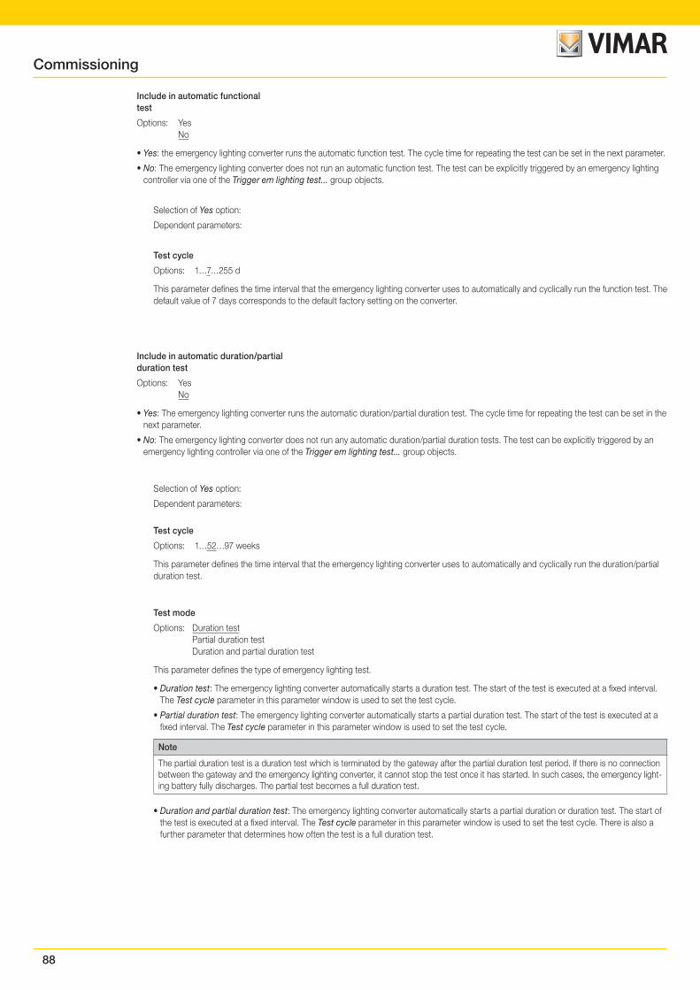
88
Include in automatic functionaltest
Options: Yes No
• Yes: the emergency lighting converter runs the automatic function test. The cycle time for repeating the test can be set in the next parameter.
• No: The emergency lighting converter does not run an automatic function test. The test can be explicitly triggered by an emergency lighting controller via one of the Trigger em lighting test... group objects.
Selection of Yes option:
Dependent parameters:
Test cycle
Options: 1…7…255 d
This parameter defines the time interval that the emergency lighting converter uses to automatically and cyclically run the function test. The default value of 7 days corresponds to the default factory setting on the converter.
Include in automatic duration/partialduration test
Options: Yes No
• Yes: The emergency lighting converter runs the automatic duration/partial duration test. The cycle time for repeating the test can be set in the next parameter.
• No: The emergency lighting converter does not run any automatic duration/partial duration tests. The test can be explicitly triggered by an emergency lighting controller via one of the Trigger em lighting test... group objects.
Selection of Yes option:
Dependent parameters:
Test cycle
Options: 1…52…97 weeks
This parameter defines the time interval that the emergency lighting converter uses to automatically and cyclically run the duration/partial duration test.
Test mode
Options: Duration test Partial duration test Duration and partial duration test
This parameter defines the type of emergency lighting test.
• Duration test: The emergency lighting converter automatically starts a duration test. The start of the test is executed at a fixed interval. The Test cycle parameter in this parameter window is used to set the test cycle.
• Partial duration test: The emergency lighting converter automatically starts a partial duration test. The start of the test is executed at a fixed interval. The Test cycle parameter in this parameter window is used to set the test cycle.
Note
The partial duration test is a duration test which is terminated by the gateway after the partial duration test period. If there is no connection between the gateway and the emergency lighting converter, it cannot stop the test once it has started. In such cases, the emergency light-ing battery fully discharges. The partial test becomes a full duration test.
• Duration and partial duration test: The emergency lighting converter automatically starts a partial duration or duration test. The start of the test is executed at a fixed interval. The Test cycle parameter in this parameter window is used to set the test cycle. There is also a further parameter that determines how often the test is a full duration test.
Commissioning
89
Selection of Duration and partial duration test:
Dependent parameters:
Duration test everyn tests
Options: 2…12…100
With alternating duration and partial duration tests, this parameter defines how often the test is a duration test.
There are three parameters below which can be used to enable group objects for each emergency lighting converter; the group objects are used to start an emergency lighting test, to obtain the test result, or to transmit converter status. These group objects relate to one converter only. The addressed emergency lighting group objects for the output (e.g. numbers 40 to 42 for output A) receive equivalent information. But there is only one addressed group object for all the converters. The information indicating which converter the group object concerns is stored in the first byte of the object – the address byte.
Enable Group objects"Trigger em lighting test"
Options: No Yes, KNX format DPT_CTC Yes, 01542 format Yes, 01542 format with status
Linked group object: Trigger em lighting test (CTC) Trigger em lighting test (01542) Trigger em lighting test/Status (01542)
• No: No group object is enabled for the emergency lighting converters to start an emergency lighting test. Regardless of this, a test can be started for the converters via the addressed group object.
• Yes, KNX DTP_CTC format: This enables a group object for the individual emergency lighting converters which triggers and stops an emer-gency lighting test. The coding of the group object corresponds to the KNX DPT specification for interworking between KNX devices.
• Yes, DGN/S1.16.1 format: This enables a group object for the individual emergency lighting converters which triggers and stops an emergen-cy lighting test. The coding for the group object corresponds to the predecessor device DGN/S1.16.1 ABB. This means that an existing KNX emergency lighting controller that has already operated with the DGN/S1.16.1 ABB can still be used, without the need for new decoding.
• Yes, DGN/S1.16.1 format with status: This enables a group object for the individual emergency lighting converters which triggers and stops an emergency lighting test. This object not only controls the test but can also provide its status. The coding for the group object corresponds to the predecessor device DGN/S1.16.1 ABB. This means that an existing KNX emergency lighting controller that has already operated with the DGN/S1.16.1 ABB can still be used, without the need for new decoding.
Selection of Yes, DGN/S1.16.1 format with status:
Dependent parameters:
Send object value
Options: On change On request After a change or on request
• On change: The status is sent when a change occurs.
• On request: The status is sent when a request occurs.
• After a change or on request: The status is sent when either a change or request occurs
Commissioning
90
"Em lighting test result"
Options: Yes No
Linked group object: Em lighting test result (6 byte)
• Yes: The Em lighting test result group object is enabled for the individual emergency lighting converters. This sends the test result for the emergency lighting test on the KNX.
• No: The status of the emergency lighting test is not sent on the KNX in a group object for each emergency lighting converter.
Selection of Yes option:
Dependent parameters:
Send object value
Options: On change On request After a change or on request
• On change: The status is sent when a change occurs.
• On request: The status is sent when a request occurs.
• After a change or on request: The status is sent when either a change or request occurs.
"Emergency lightingconverter status"
Options: Yes No
Linked group object: "Emergency lighting converter status" (2 byte)
• Yes: The Emergency lighting converter status group object is enabled. This sends the status of the emergency lighting converter on the KNX.
• No: The status of the emergency lighting converter is not sent on the KNX in a group object for each converter.
Selection of Yes option:
Dependent parameters:
Send object value
Options: On change On request After a change or on request
• On change: The status is sent when a change occurs.
• On request: The status is sent when a request occurs.
• After a change or on request: The status is sent when either a change or request occurs.
Commissioning
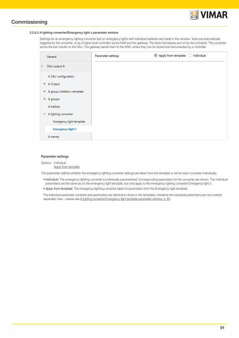
91
3.2.6.2 A lighting converter/Emergency light x parameter window
Settings for an emergency lighting converter test on emergency lights with individual batteries are made in this window. Tests are automatically triggered by the converter, or by a higher level controller via the KNX and the gateway. The tests themselves are run by the converter. The converter sends the test results on the DALI. The gateway sends them to the KNX, where they can be stored and documented by a controller.
Parameter settings
Options: Individual Apply from template
This parameter defines whether the emergency lighting converter settings are taken from the template or set for each converter individually.
• Individual: The emergency lighting converter is individually parametrized. Corresponding parameters for the converter are shown. The individual parameters are the same as on the emergency light template, but only apply to the emergency lighting converter Emergency light x..
• Apply from template: The emergency lighting converter takes its parameters from the Emergency light template.
The individual parameter windows and parameters are identical to those in the templates, therefore the individual parameters are not covered separately here – please see A lighting converter/Emergency light template parameter window, p. 85.
Commissioning
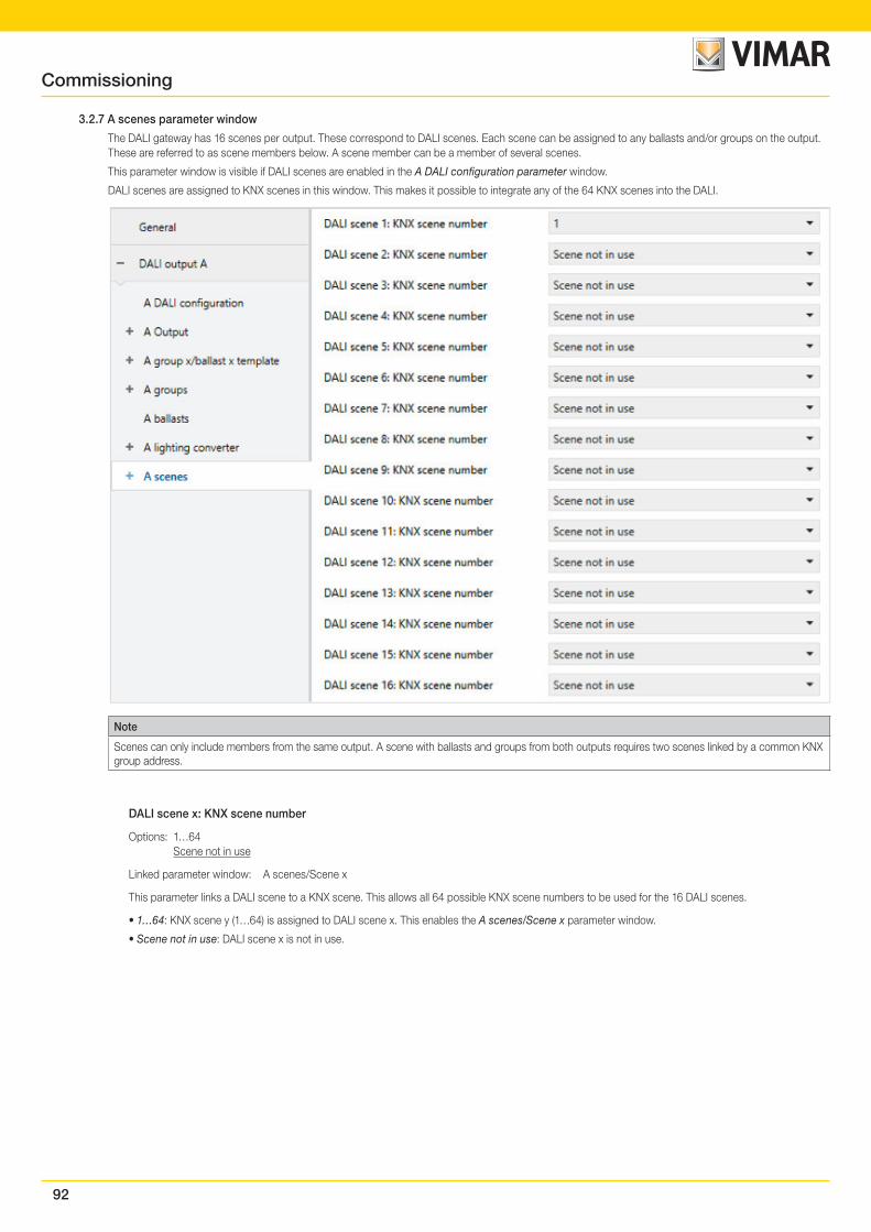
92
3.2.7 A scenes parameter window
The DALI gateway has 16 scenes per output. These correspond to DALI scenes. Each scene can be assigned to any ballasts and/or groups on the output. These are referred to as scene members below. A scene member can be a member of several scenes.
This parameter window is visible if DALI scenes are enabled in the A DALI configuration parameter window.
DALI scenes are assigned to KNX scenes in this window. This makes it possible to integrate any of the 64 KNX scenes into the DALI.
Note
Scenes can only include members from the same output. A scene with ballasts and groups from both outputs requires two scenes linked by a common KNX group address.
DALI scene x: KNX scene number
Options: 1…64 Scene not in use
Linked parameter window: A scenes/Scene x
This parameter links a DALI scene to a KNX scene. This allows all 64 possible KNX scene numbers to be used for the 16 DALI scenes.
• 1…64: KNX scene y (1…64) is assigned to DALI scene x. This enables the A scenes/Scene x parameter window.
• Scene not in use: DALI scene x is not in use.
Commissioning
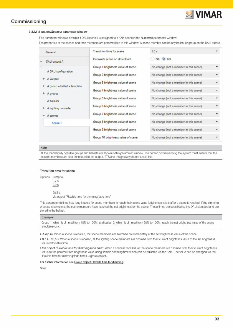
93
3.2.7.1 A scenes/Scene x parameter window
This parameter window is visible if DALI scene x is assigned to a KNX scene in the A scenes parameter window.
The properties of the scenes and their members are parametrized in this window. A scene member can be any ballast or group on the DALI output.
Note
All the theoretically possible groups and ballasts are shown in this parameter window. The person commissioning the system must ensure that the required members are also connected to the output. ETS and the gateway do not check this.
Transition time for scene
Options: Jump to 0,7 s 2,0 s … 90,5 s Via object "Flexible time for dimming/fade time"
This parameter defines how long it takes for scene members to reach their scene value (brightness value) after a scene is recalled. If the dimming process is complete, the scene members have reached the set brightness for the scene. These times are specified by the DALI standard and are stored in the ballast.
Example
Group 1, which is dimmed from 10% to 100%, and ballast 2, which is dimmed from 90% to 100%, reach the set brightness value of the scene simultaneously.
• Jump to: When a scene is recalled, the scene members are switched on immediately at the set brightness value of the scene.
• 0,7 s…90,5 s: When a scene is recalled, all the lighting scene members are dimmed from their current brightness value to the set brightness value within this time.
• Via object "Flexible time for dimming/fade time": When a scene is recalled, all the scene members are dimmed from their current brightness value to the parametrized brightness value using flexible dimming time which can be adjusted via the KNX. The value can be changed via the Flexible time for dimming/fade time (...) group object..
For further information see Group object Flexible time for dimming.
Note:
Commissioning
94
Note
Flexible dimming time is received via the Output A Flexible time for dimming/fade time group object and affects various output functions:
• Dimming time for turn on/off value
• Dimming time for brightness value
• Dimming time for slave brightness value
• Scene transition time
To use the Flexible dimming time function you first need to enable the output's Flexible time for dimming/fade time group object in the A Output/Functions parameter window. You also need to select the function for the parameter that can be changed via KNX. We recommend that you only change one time via KNX. Otherwise the dimming time has to be rewritten on the ballast every time a function is called, which impairs function performance.
Overwrite scene on download
Options: Yes No
When a download occurs, the parametrized scene values are usually transferred to the gateway. This parameter can prohibit the transfer so as to prevent manually set scene values from being overwritten. Instead, the scene values saved via KNX are retained.
• Yes: After a download or KNX bus voltage recovery, the scene values for the scene members are overwritten with the values set in ETS.
• No: After a download or KNX bus voltage recovery, the scene values for the scene members are not overwritten with the values set in ETS. If no scene values have been stored, the gateway sets them to the maximum brightness.
Note
When a scene is recalled or stored, only the ballasts or groups in that scene are taken into consideration.
Note
Even if the scene values are not overwritten after a download, the scene members have to be selected in order to tell the gateway which ballasts or groups are members of the scene.
Note
When a download occurs, the parametrized scene values are usually transferred to the gateway. Note that if no change has been made in the ETS application, ETS does not transfer these values again when a partial ETS download occurs. To transfer the values to the gateway even when no parameters have been changed, run a normal download using "Program application program".
Group x brightness value of scene orBallast x brightness value of scene
Options: No change (not a member in this scene)) 100% (255) 99% (252) … 1% (3) 0% (OFF)
This parameter defines the brightness value to which scene members are set when a scene is recalled.
• No change (not a member in this scene): The ballast or group is not part of this scene and is not affected by a scene recall. The current bright-ness value of remains unchanged and even when the scene is stored via the KNX, the brightness value is not stored in the ballast.
• 100 % (255)…0 % (OFF): The ballast or group is part of the scene. During a scene recall, the scene member is set to the brightness value para-metrized here. If the set brightness value is above or below the maximum brightness or minimal dimming value defined for the scene member in question, the corresponding dimming value is stored in the scene.
Commissioning
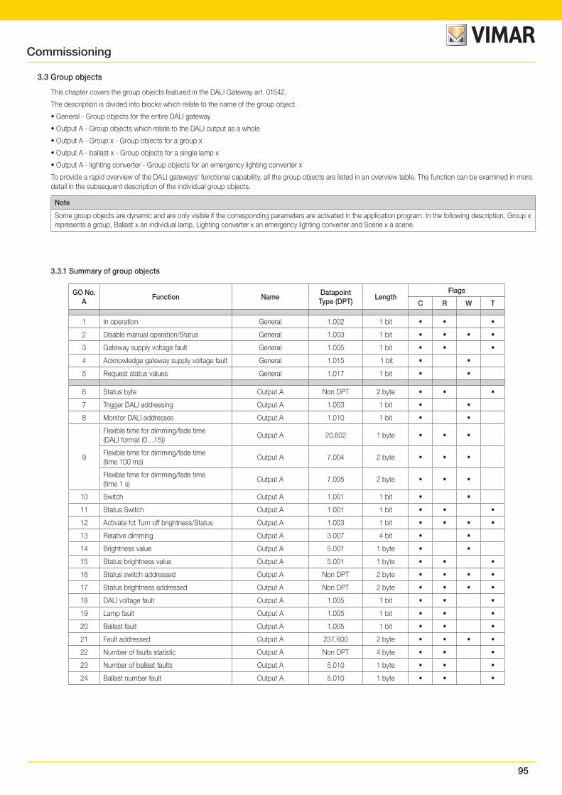
95
3.3 Group objects
This chapter covers the group objects featured in the DALI Gateway art. 01542.
The description is divided into blocks which relate to the name of the group object.
• General - Group objects for the entire DALI gateway
• Output A - Group objects which relate to the DALI output as a whole
• Output A - Group x - Group objects for a group x
• Output A - ballast x - Group objects for a single lamp x
• Output A - lighting converter - Group objects for an emergency lighting converter x
To provide a rapid overview of the DALI gateways' functional capability, all the group objects are listed in an overview table. The function can be examined in more detail in the subsequent description of the individual group objects.
Note
Some group objects are dynamic and are only visible if the corresponding parameters are activated in the application program. In the following description, Group x represents a group, Ballast x an individual lamp, Lighting converter x an emergency lighting converter and Scene x a scene.
3.3.1 Summary of group objects
GO No.A
Function NameDatapoint Type (DPT)
LengthFlags
C R W T
1 In operation General 1.002 1 bit • • •
2 Disable manual operation/Status General 1.003 1 bit • • • •
3 Gateway supply voltage fault General 1.005 1 bit • • •
4 Acknowledge gateway supply voltage fault General 1.015 1 bit • •
5 Request status values General 1.017 1 bit • •
6 Status byte Output A Non DPT 2 byte • • •
7 Trigger DALI addressing Output A 1.003 1 bit • •
8 Monitor DALI addresses Output A 1.010 1 bit • •
9
Flexible time for dimming/fade time (DALI format (0…15))
Output A 20.602 1 byte • • •
Flexible time for dimming/fade time (time 100 ms)
Output A 7.004 2 byte • • •
Flexible time for dimming/fade time(time 1 s)
Output A 7.005 2 byte • • •
10 Switch Output A 1.001 1 bit • •
11 Status Switch Output A 1.001 1 bit • • •
12 Activate fct Turn off brightness/Status Output A 1.003 1 bit • • • •
13 Relative dimming Output A 3.007 4 bit • •
14 Brightness value Output A 5.001 1 byte • •
15 Status brightness value Output A 5.001 1 byte • • •
16 Status switch addressed Output A Non DPT 2 byte • • • •
17 Status brightness addressed Output A Non DPT 2 byte • • • •
18 DALI voltage fault Output A 1.005 1 bit • • •
19 Lamp fault Output A 1.005 1 bit • • •
20 Ballast fault Output A 1.005 1 bit • • •
21 Fault addressed Output A 237.600 2 byte • • • •
22 Number of faults statistic Output A Non DPT 4 byte • • •
23 Number of ballast faults Output A 5.010 1 byte • • •
24 Ballast number fault Output A 5.010 1 byte • • •
Commissioning
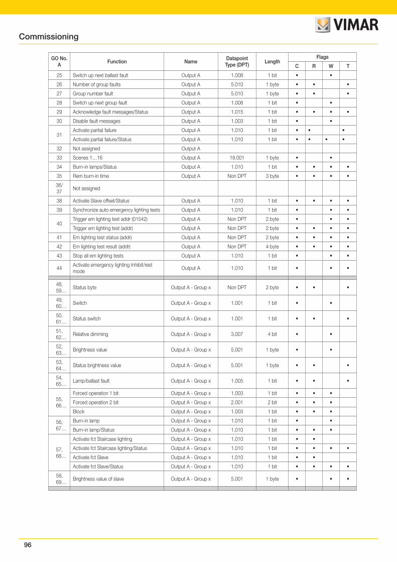
96
GO No.A
Function NameDatapoint Type (DPT)
LengthFlags
C R W T
25 Switch up next ballast fault Output A 1.008 1 bit • •
26 Number of group faults Output A 5.010 1 byte • • •
27 Group number fault Output A 5.010 1 byte • • •
28 Switch up next group fault Output A 1.008 1 bit • •
29 Acknowledge fault messages/Status Output A 1.015 1 bit • • • •
30 Disable fault messages Output A 1.003 1 bit • •
31Activate partial failure Output A 1.010 1 bit • • •
Activate partial failure/Status Output A 1.010 1 bit • • • •
32 Not assigned Output A
33 Scenes 1…16 Output A 18.001 1 byte • •
34 Burn-in lamps/Status Output A 1.010 1 bit • • • •
35 Rem burn-in time Output A Non DPT 3 byte • • • •
36/37
Not assigned
38 Activate Slave offset/Status Output A 1.010 1 bit • • • •
39 Synchronize auto emergency lighting tests Output A 1.010 1 bit • • •
40Trigger em lighting test addr (01542) Output A Non DPT 2 byte • • •
Trigger em lighting test (addr) Output A Non DPT 2 byte • • • •
41 Em lighting test status (addr) Output A Non DPT 2 byte • • • •
42 Em lighting test result (addr) Output A Non DPT 4 byte • • • •
43 Stop all em lighting tests Output A 1.010 1 bit • • •
44Activate emergency lighting Inhibit/rest mode
Output A 1.010 1 bit • • •
48, 59…
Status byte Output A - Group x Non DPT 2 byte • • •
49, 60…
Switch Output A - Group x 1.001 1 bit • •
50, 61…
Status switch Output A - Group x 1.001 1 bit • • •
51, 62…
Relative dimming Output A - Group x 3.007 4 bit • •
52, 63…
Brightness value Output A - Group x 5.001 1 byte • •
53, 64…
Status brightness value Output A - Group x 5.001 1 byte • • •
54, 65…
Lamp/ballast fault Output A - Group x 1.005 1 bit • • •
55, 66…
Forced operation 1 bit Output A - Group x 1.003 1 bit • • •
Forced operation 2 bit Output A - Group x 2.001 2 bit • • •
Block Output A - Group x 1.003 1 bit • • •
56, 67…
Burn-in lamp Output A - Group x 1.010 1 bit • •
Burn-in lamp/Status Output A - Group x 1.010 1 bit • • •
57, 68…
Activate fct Staircase lighting Output A - Group x 1.010 1 bit • •
Activate fct Staircase lighting/Status Output A - Group x 1.010 1 bit • • • •
Activate fct Slave Output A - Group x 1.010 1 bit • •
Activate fct Slave/Status Output A - Group x 1.010 1 bit • • • •
58, 69…
Brightness value of slave Output A - Group x 5.001 1 byte • • •
Commissioning

97
GO No.A
Function NameDatapoint Type (DPT)
LengthFlags
C R W T
224, 235,,,
Status byte Output A - Ballast x Non DTP 2 byte • • •
225, 236…
Switch Output A - Ballast x 1.001 1 bit • •
Switch/Status Output A - Ballast x 1.001 1 bit • • • •
226 237
Status switch Output A - Ballast x 1.001 1 bit • • •
227, 238…
Relative dimming Output A - Ballast x 3.007 4 bit • •
228, 239…
Brightness value Output A - Ballast x 5.001 1 byte • •
Brightness value/Status Output A - Ballast x 5.001 1 byte • • • •
229, 240…
Status brightness value Output A - Ballast x 5.001 1 byte • • •
230, 241…
Lamp/ballast fault Output A - Ballast x 1.005 1 bit • • •
231, 242…
Forced operation 1 bit Output A - Ballast x 1.003 1 bit • • •
Forced operation 2 bit Output A - Ballast x 2.001 2 bit • • •
Block Output A - Ballast x 1.003 1 bit • • •
232, 243…
Burn-in lamp Output A - Ballast x 1.010 1 bit • •
Burn-in lamp/Status Output A - Ballast x 1.010 1 bit • • •
233, 244…
Activate fct Staircase lighting Output A - Ballast x 1.010 1 bit • •
Activate fct Staircase lighting/Status Output A - Ballast x 1.010 1 bit • • • •
Activate fct Slave Output A - Ballast x 1.010 1 bit • •
Activate fct Slave/Status Output A - Ballast x 1.010 1 bit • • • •
234, 245
Brightness value of slave Output A - Ballast x 5.001 1 byte • • •
928, 931…
Trigger em lighting test (CTC)Output A -
Emergency light xDPT_CTC 1 byte • •
Trigger em lighting test (01542)Output A -
Emergency light xLEGACY CTT
2.8.2.81 byte • •
Trigger em lighting test/Status (01542)Output A -
Emergency light xLEGACY CTTS
2.8.2.51 byte • • •
929, 932…
Em lighting test resultOutput A -
Emergency light xDPT_CTR 6 byte • • •
930, 933…
Emergency lighting converter statusOutput A -
Emergency light xDPT_CS 2 byte • • •
* GO = group object
Commissioning
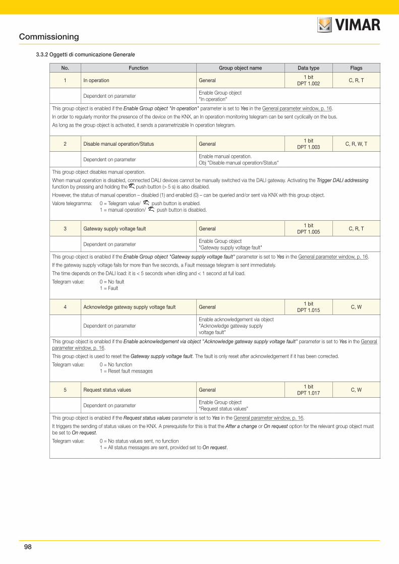
98
Commissioning
3.3.2 Oggetti di comunicazione Generale
No. Function Group object name Data type Flags
1 In operation General1 bit
DPT 1.002C, R, T
Dependent on parameterEnable Group object "In operation"
This group object is enabled if the Enable Group object "In operation" parameter is set to Yes in the General parameter window, p. 16.
In order to regularly monitor the presence of the device on the KNX, an In operation monitoring telegram can be sent cyclically on the bus.
As long as the group object is activated, it sends a parametrizable In operation telegram.
2 Disable manual operation/Status General1 bit
DPT 1.003C, R, W, T
Dependent on parameterEnable manual operation. Obj "Disable manual operation/Status"
This group object disables manual operation.
When manual operation is disabled, connected DALI devices cannot be manually switched via the DALI gateway. Activating the Trigger DALI addressing function by pressing and holding the push button (> 5 s) is also disabled.
However, the status of manual operation – disabled (1) and enabled (0) – can be queried and/or sent via KNX with this group object.
Valore telegramma: 0 = Telegram value/ push button is enabled. 1 = manual operation/ push button is disabled.
3 Gateway supply voltage fault General1 bit
DPT 1.005C, R, T
Dependent on parameterEnable Group object "Gateway supply voltage fault"
This group object is enabled if the Enable Group object "Gateway supply voltage fault" parameter is set to Yes in the General parameter window, p. 16.
If the gateway supply voltage fails for more than five seconds, a Fault message telegram is sent immediately.
The time depends on the DALI load: it is < 5 seconds when idling and < 1 second at full load.
Telegram value: 0 = No fault 1 = Fault
4 Acknowledge gateway supply voltage fault General1 bit
DPT 1.015C, W
Dependent on parameterEnable acknowledgement via object "Acknowledge gateway supply voltage fault"
This group object is enabled if the Enable acknowledgement via object "Acknowledge gateway supply voltage fault" parameter is set to Yes in the General parameter window, p. 16.
This group object is used to reset the Gateway supply voltage fault. The fault is only reset after acknowledgement if it has been corrected.
Telegram value: 0 = No function 1 = Reset fault messages
5 Request status values General1 bit
DPT 1.017C, W
Dependent on parameterEnable Group object "Request status values"
This group object is enabled if the Request status values parameter is set to Yes in the General parameter window, p. 16.
It triggers the sending of status values on the KNX. A prerequisite for this is that the After a change or On request option for the relevant group object must be set to On request.
Telegram value: 0 = No status values sent, no function 1 = All status messages are sent, provided set to On request.
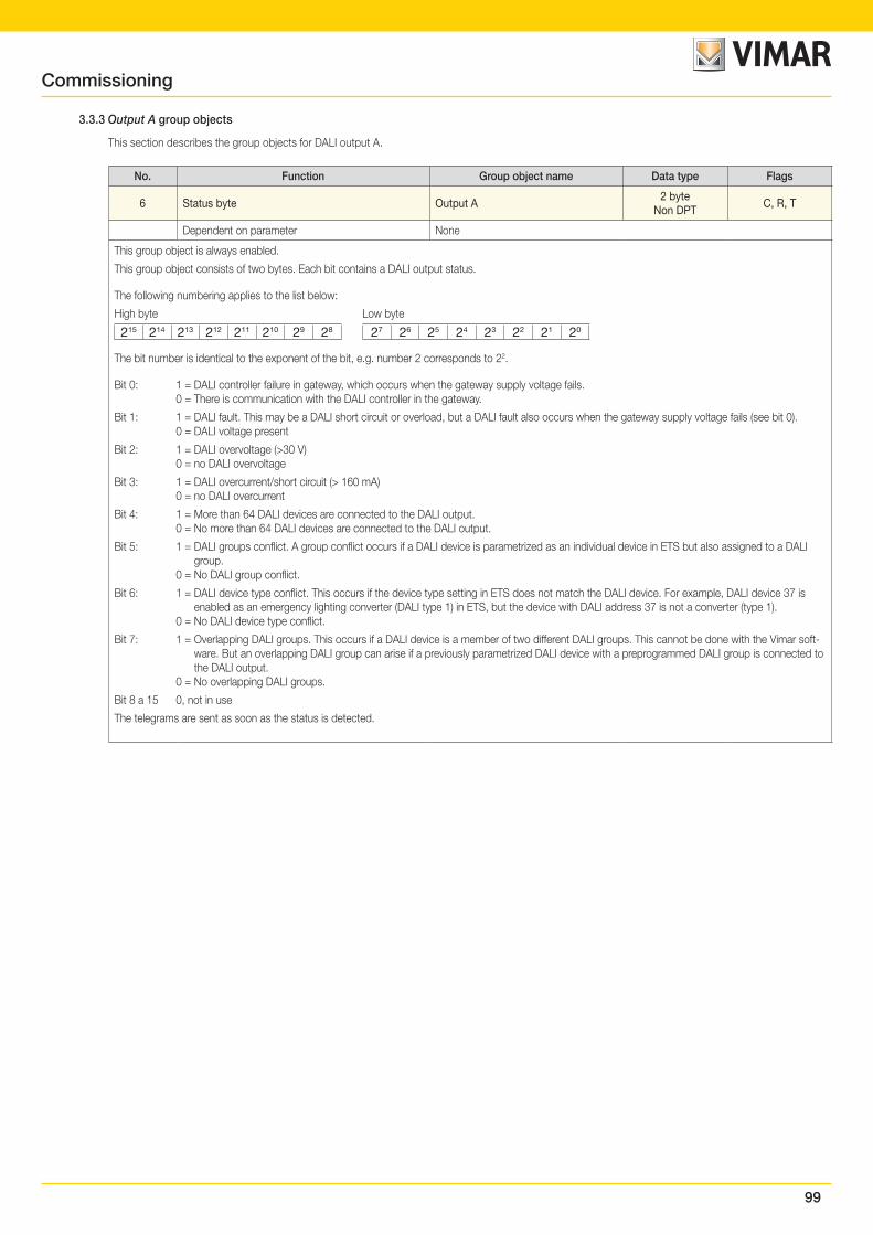
99
Commissioning
No. Function Group object name Data type Flags
6 Status byte Output A2 byte
Non DPTC, R, T
Dependent on parameter None
This group object is always enabled.
This group object consists of two bytes. Each bit contains a DALI output status.
The following numbering applies to the list below:
High byte Low byte
215 214 213 212 211 210 29 28 27 26 25 24 23 22 21 20
The bit number is identical to the exponent of the bit, e.g. number 2 corresponds to 22.
Bit 0: 1 = DALI controller failure in gateway, which occurs when the gateway supply voltage fails. 0 = There is communication with the DALI controller in the gateway.
Bit 1: 1 = DALI fault. This may be a DALI short circuit or overload, but a DALI fault also occurs when the gateway supply voltage fails (see bit 0). 0 = DALI voltage present
Bit 2: 1 = DALI overvoltage (>30 V) 0 = no DALI overvoltage
Bit 3: 1 = DALI overcurrent/short circuit (> 160 mA) 0 = no DALI overcurrent
Bit 4: 1 = More than 64 DALI devices are connected to the DALI output. 0 = No more than 64 DALI devices are connected to the DALI output.
Bit 5: 1 = DALI groups conflict. A group conflict occurs if a DALI device is parametrized as an individual device in ETS but also assigned to a DALI group.
0 = No DALI group conflict.
Bit 6: 1 = DALI device type conflict. This occurs if the device type setting in ETS does not match the DALI device. For example, DALI device 37 is enabled as an emergency lighting converter (DALI type 1) in ETS, but the device with DALI address 37 is not a converter (type 1).
0 = No DALI device type conflict.
Bit 7: 1 = Overlapping DALI groups. This occurs if a DALI device is a member of two different DALI groups. This cannot be done with the Vimar soft-ware. But an overlapping DALI group can arise if a previously parametrized DALI device with a preprogrammed DALI group is connected to the DALI output.
0 = No overlapping DALI groups.
Bit 8 a 15 0, not in use
The telegrams are sent as soon as the status is detected.
3.3.3 Output A group objects
This section describes the group objects for DALI output A.
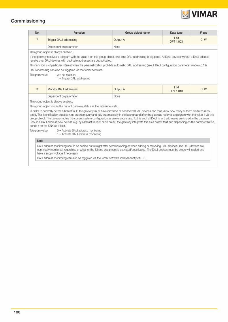
100
Commissioning
No. Function Group object name Data type Flags
7 Trigger DALI addressing Output A1 bit
DPT 1.003C, W
Dependent on parameter None
This group object is always enabled.
If the gateway receives a telegram with the value 1 on this group object, one-time DALI addressing is triggered. All DALI devices without a DALI address receive one. DALI devices with duplicate addresses are deduplicated.
This function is of particular interest when the parametrization prohibits automatic DALI addressing (see A DALI configuration parameter window p.19).
DALI addressing can also be triggered via the Vimar software.
Telegram value: 0 = No reaction 1 = Trigger DALI addressing
8 Monitor DALI addresses Output A1 bit
DPT 1.010C, W
Dependent on parameter None
This group object is always enabled.
This group object stores the current gateway status as the reference state.
In order to correctly detect a ballast fault, the gateway must have identified all connected DALI devices and thus know how many of them are to be moni-tored. This identification process runs autonomously and fully automatically in the background after the gateway receives a telegram with the value 1 via this group object. The gateway notes the current system configuration as a reference state. To this end, all DALI (short) addresses are stored in the gateway. Should a DALI address now be lost, e.g. by a ballast fault or cable break, the gateway interprets this as a ballast fault and depending on the parametrization, sends it on the KNX as a fault.
Telegram value: 0 = Activate DALI address monitoring 1 = Activate DALI address monitoring
Note
DALI address monitoring should be carried out straight after commissioning or when adding or removing DALI devices. The DALI devices are continually monitored, regardless of whether the lighting equipment is activated/deactivated. The DALI devices must be properly installed and have a supply voltage if necessary.
DALI address monitoring can also be triggered via the Vimar software independently of ETS.
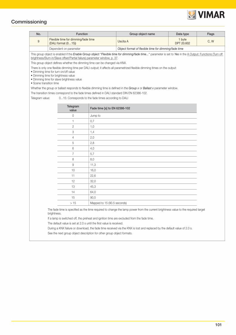
101
Commissioning
No. Function Group object name Data type Flags
9Flexible time for dimming/fade time(DALI format (0…15))
Uscita A1 byte
DPT 20.602C, W
Dependent on parameter Object format of flexible time for dimming/fade time
This group object is enabled if the Enable Group object "Flexible time for dimming/fade time..." parameter is set to Yes in the A Output: Functions (Turn off brightness/Burn-in/Slave offset/Partial failure) parameter window, p. 37.
This group object defines whether the dimming time can be changed via KNX.
There is only one flexible dimming time per DALI output; it affects all parametrized flexible dimming times on the output:• Dimming time for turn on/off value• Dimming time for brightness value• Dimming time for slave brightness value• Scene transition time
Whether the group or ballast responds to flexible dimming time is defined in the Group x or Ballast x parameter window.
The transition times correspond to the fade times defined in DALI standard DIN EN 62386-102.
Telegram value: 0...15: Corresponds to the fade times according to DALI
Telegramvalue
Fade time [s] to EN 62386-102
0 Jump to
1 0,7
2 1,0
3 1,4
4 2,0
5 2,8
6 4,0
7 5,7
8 8,0
9 11,3
10 16,0
11 22,6
12 32,0
13 45,3
14 64,0
15 90,5
> 15 Mapped to 15 (90.5 seconds)
The fade time is specified as the time required to change the lamp power from the current brightness value to the required target brightness.
If a lamp is switched off, the preheat and ignition time are excluded from the fade time.
The default value is set at 2.0 s until the first value is received.
During a KNX failure or download, the fade time received via the KNX is lost and replaced by the default value of 2.0 s.
See the next group object description for other group object formats.
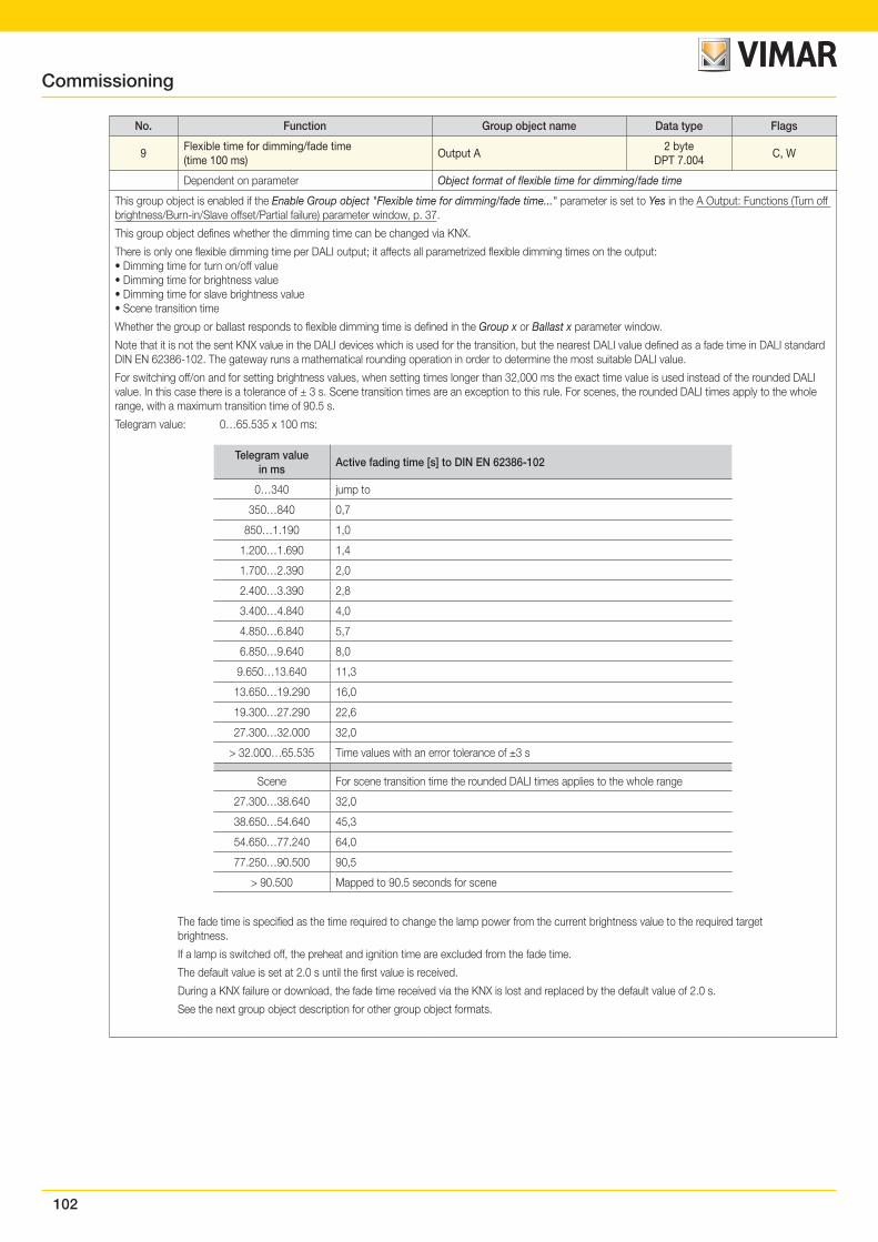
102
No. Function Group object name Data type Flags
9Flexible time for dimming/fade time(time 100 ms)
Output A2 byte
DPT 7.004C, W
Dependent on parameter Object format of flexible time for dimming/fade time
This group object is enabled if the Enable Group object "Flexible time for dimming/fade time..." parameter is set to Yes in the A Output: Functions (Turn off brightness/Burn-in/Slave offset/Partial failure) parameter window, p. 37.
This group object defines whether the dimming time can be changed via KNX.
There is only one flexible dimming time per DALI output; it affects all parametrized flexible dimming times on the output:• Dimming time for turn on/off value• Dimming time for brightness value• Dimming time for slave brightness value• Scene transition time
Whether the group or ballast responds to flexible dimming time is defined in the Group x or Ballast x parameter window.
Note that it is not the sent KNX value in the DALI devices which is used for the transition, but the nearest DALI value defined as a fade time in DALI standard DIN EN 62386-102. The gateway runs a mathematical rounding operation in order to determine the most suitable DALI value.
For switching off/on and for setting brightness values, when setting times longer than 32,000 ms the exact time value is used instead of the rounded DALI value. In this case there is a tolerance of ± 3 s. Scene transition times are an exception to this rule. For scenes, the rounded DALI times apply to the whole range, with a maximum transition time of 90.5 s.
Telegram value: 0…65.535 x 100 ms:
Telegram valuein ms
Active fading time [s] to DIN EN 62386-102
0…340 jump to
350…840 0,7
850…1.190 1,0
1.200…1.690 1,4
1.700…2.390 2,0
2.400…3.390 2,8
3.400…4.840 4,0
4.850…6.840 5,7
6.850…9.640 8,0
9.650…13.640 11,3
13.650…19.290 16,0
19.300…27.290 22,6
27.300…32.000 32,0
> 32.000…65.535 Time values with an error tolerance of ±3 s
Scene For scene transition time the rounded DALI times applies to the whole range
27.300…38.640 32,0
38.650…54.640 45,3
54.650…77.240 64,0
77.250…90.500 90,5
> 90.500 Mapped to 90.5 seconds for scene
The fade time is specified as the time required to change the lamp power from the current brightness value to the required target brightness.
If a lamp is switched off, the preheat and ignition time are excluded from the fade time.
The default value is set at 2.0 s until the first value is received.
During a KNX failure or download, the fade time received via the KNX is lost and replaced by the default value of 2.0 s.
See the next group object description for other group object formats.
Commissioning
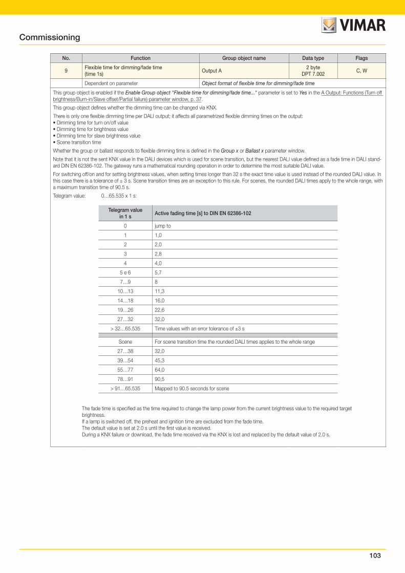
103
No. Function Group object name Data type Flags
9Flexible time for dimming/fade time(time 1s)
Output A2 byte
DPT 7.002C, W
Dependent on parameter Object format of flexible time for dimming/fade time
This group object is enabled if the Enable Group object "Flexible time for dimming/fade time..." parameter is set to Yes in the A Output: Functions (Turn off brightness/Burn-in/Slave offset/Partial failure) parameter window, p. 37.
This group object defines whether the dimming time can be changed via KNX.
There is only one flexible dimming time per DALI output; it affects all parametrized flexible dimming times on the output:• Dimming time for turn on/off value• Dimming time for brightness value• Dimming time for slave brightness value• Scene transition time
Whether the group or ballast responds to flexible dimming time is defined in the Group x or Ballast x parameter window.
Note that it is not the sent KNX value in the DALI devices which is used for scene transition, but the nearest DALI value defined as a fade time in DALI stand-ard DIN EN 62386-102. The gateway runs a mathematical rounding operation in order to determine the most suitable DALI value.
For switching off/on and for setting brightness values, when setting times longer than 32 s the exact time value is used instead of the rounded DALI value. In this case there is a tolerance of ± 3 s. Scene transition times are an exception to this rule. For scenes, the rounded DALI times apply to the whole range, with a maximum transition time of 90.5 s.
Telegram value: 0…65.535 x 1 s:
Telegram valuein 1 s
Active fading time [s] to DIN EN 62386-102
0 jump to
1 1,0
2 2,0
3 2,8
4 4,0
5 e 6 5,7
7…9 8
10…13 11,3
14…18 16,0
19…26 22,6
27…32 32,0
> 32…65.535 Time values with an error tolerance of ±3 s
Scene For scene transition time the rounded DALI times applies to the whole range
27…38 32,0
39…54 45,3
55…77 64,0
78…91 90,5
> 91…65.535 Mapped to 90.5 seconds for scene
The fade time is specified as the time required to change the lamp power from the current brightness value to the required target brightness.If a lamp is switched off, the preheat and ignition time are excluded from the fade time.The default value is set at 2.0 s until the first value is received.During a KNX failure or download, the fade time received via the KNX is lost and replaced by the default value of 2.0 s.
Commissioning
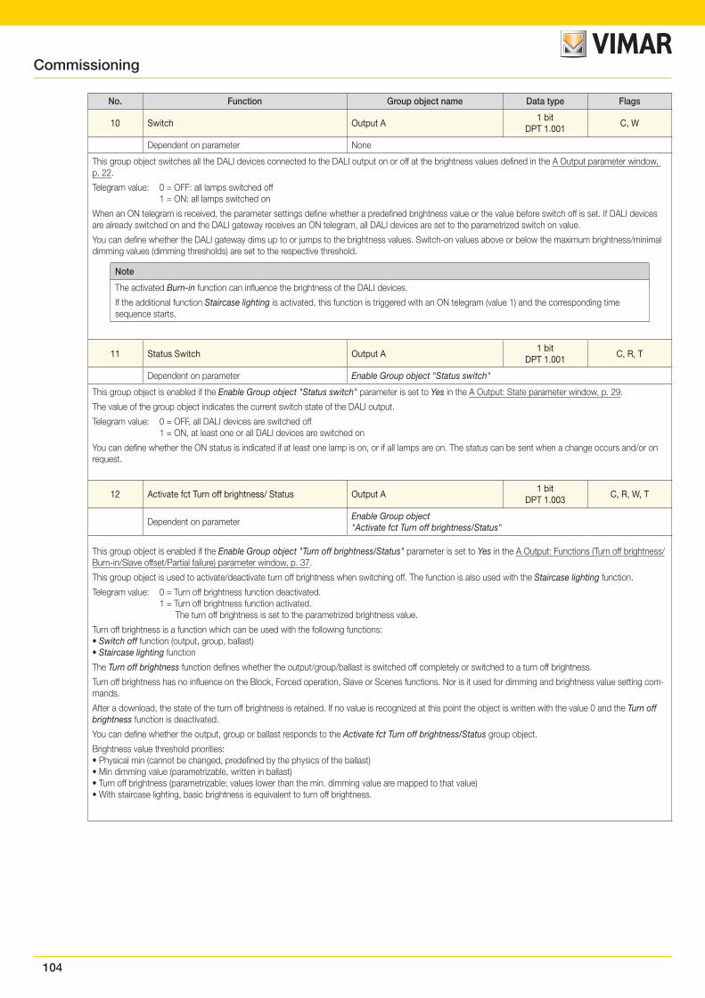
104
No. Function Group object name Data type Flags
10 Switch Output A1 bit
DPT 1.001C, W
Dependent on parameter None
This group object switches all the DALI devices connected to the DALI output on or off at the brightness values defined in the A Output parameter window, p. 22.
Telegram value: 0 = OFF: all lamps switched off 1 = ON: all lamps switched on
When an ON telegram is received, the parameter settings define whether a predefined brightness value or the value before switch off is set. If DALI devices are already switched on and the DALI gateway receives an ON telegram, all DALI devices are set to the parametrized switch on value.
You can define whether the DALI gateway dims up to or jumps to the brightness values. Switch-on values above or below the maximum brightness/minimal dimming values (dimming thresholds) are set to the respective threshold.
Note
The activated Burn-in function can influence the brightness of the DALI devices.
If the additional function Staircase lighting is activated, this function is triggered with an ON telegram (value 1) and the corresponding time sequence starts.
11 Status Switch Output A1 bit
DPT 1.001C, R, T
Dependent on parameter Enable Group object "Status switch"
This group object is enabled if the Enable Group object "Status switch" parameter is set to Yes in the A Output: State parameter window, p. 29.
The value of the group object indicates the current switch state of the DALI output.
Telegram value: 0 = OFF, all DALI devices are switched off 1 = ON, at least one or all DALI devices are switched on
You can define whether the ON status is indicated if at least one lamp is on, or if all lamps are on. The status can be sent when a change occurs and/or on request.
12 Activate fct Turn off brightness/ Status Output A1 bit
DPT 1.003C, R, W, T
Dependent on parameterEnable Group object "Activate fct Turn off brightness/Status"
This group object is enabled if the Enable Group object "Turn off brightness/Status" parameter is set to Yes in the A Output: Functions (Turn off brightness/Burn-in/Slave offset/Partial failure) parameter window, p. 37.
This group object is used to activate/deactivate turn off brightness when switching off. The function is also used with the Staircase lighting function.
Telegram value: 0 = Turn off brightness function deactivated. 1 = Turn off brightness function activated. The turn off brightness is set to the parametrized brightness value.
Turn off brightness is a function which can be used with the following functions:• Switch off function (output, group, ballast)• Staircase lighting function
The Turn off brightness function defines whether the output/group/ballast is switched off completely or switched to a turn off brightness.
Turn off brightness has no influence on the Block, Forced operation, Slave or Scenes functions. Nor is it used for dimming and brightness value setting com-mands.
After a download, the state of the turn off brightness is retained. If no value is recognized at this point the object is written with the value 0 and the Turn off brightness function is deactivated.
You can define whether the output, group or ballast responds to the Activate fct Turn off brightness/Status group object.
Brightness value threshold priorities:• Physical min (cannot be changed, predefined by the physics of the ballast)• Min dimming value (parametrizable, written in ballast)• Turn off brightness (parametrizable; values lower than the min. dimming value are mapped to that value)• With staircase lighting, basic brightness is equivalent to turn off brightness.
Commissioning
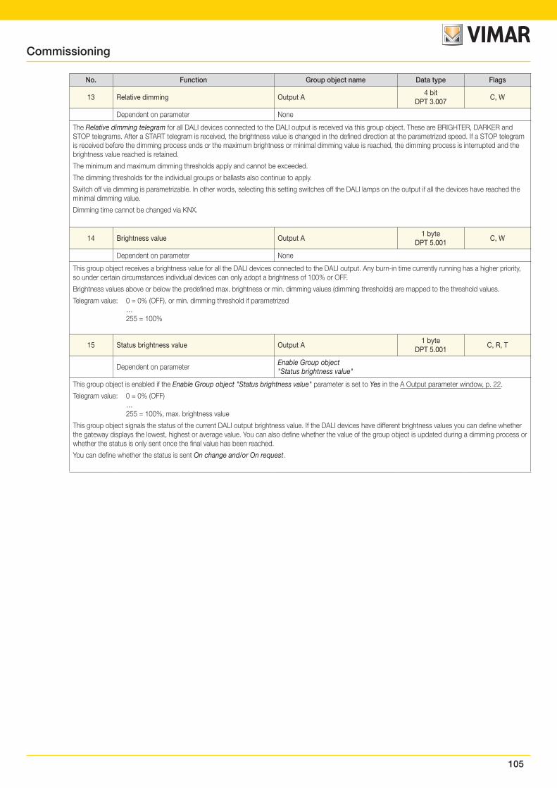
105
No. Function Group object name Data type Flags
13 Relative dimming Output A4 bit
DPT 3.007C, W
Dependent on parameter None
The Relative dimming telegram for all DALI devices connected to the DALI output is received via this group object. These are BRIGHTER, DARKER and STOP telegrams. After a START telegram is received, the brightness value is changed in the defined direction at the parametrized speed. If a STOP telegram is received before the dimming process ends or the maximum brightness or minimal dimming value is reached, the dimming process is interrupted and the brightness value reached is retained.
The minimum and maximum dimming thresholds apply and cannot be exceeded.
The dimming thresholds for the individual groups or ballasts also continue to apply.
Switch off via dimming is parametrizable. In other words, selecting this setting switches off the DALI lamps on the output if all the devices have reached the minimal dimming value.
Dimming time cannot be changed via KNX.
14 Brightness value Output A1 byte
DPT 5.001C, W
Dependent on parameter None
This group object receives a brightness value for all the DALI devices connected to the DALI output. Any burn-in time currently running has a higher priority, so under certain circumstances individual devices can only adopt a brightness of 100% or OFF.
Brightness values above or below the predefined max. brightness or min. dimming values (dimming thresholds) are mapped to the threshold values.
Telegram value: 0 = 0% (OFF), or min. dimming threshold if parametrized … 255 = 100%
15 Status brightness value Output A1 byte
DPT 5.001C, R, T
Dependent on parameterEnable Group object "Status brightness value"
This group object is enabled if the Enable Group object "Status brightness value" parameter is set to Yes in the A Output parameter window, p. 22.
Telegram value: 0 = 0% (OFF) … 255 = 100%, max. brightness value
This group object signals the status of the current DALI output brightness value. If the DALI devices have different brightness values you can define whether the gateway displays the lowest, highest or average value. You can also define whether the value of the group object is updated during a dimming process or whether the status is only sent once the final value has been reached.
You can define whether the status is sent On change and/or On request.
Commissioning
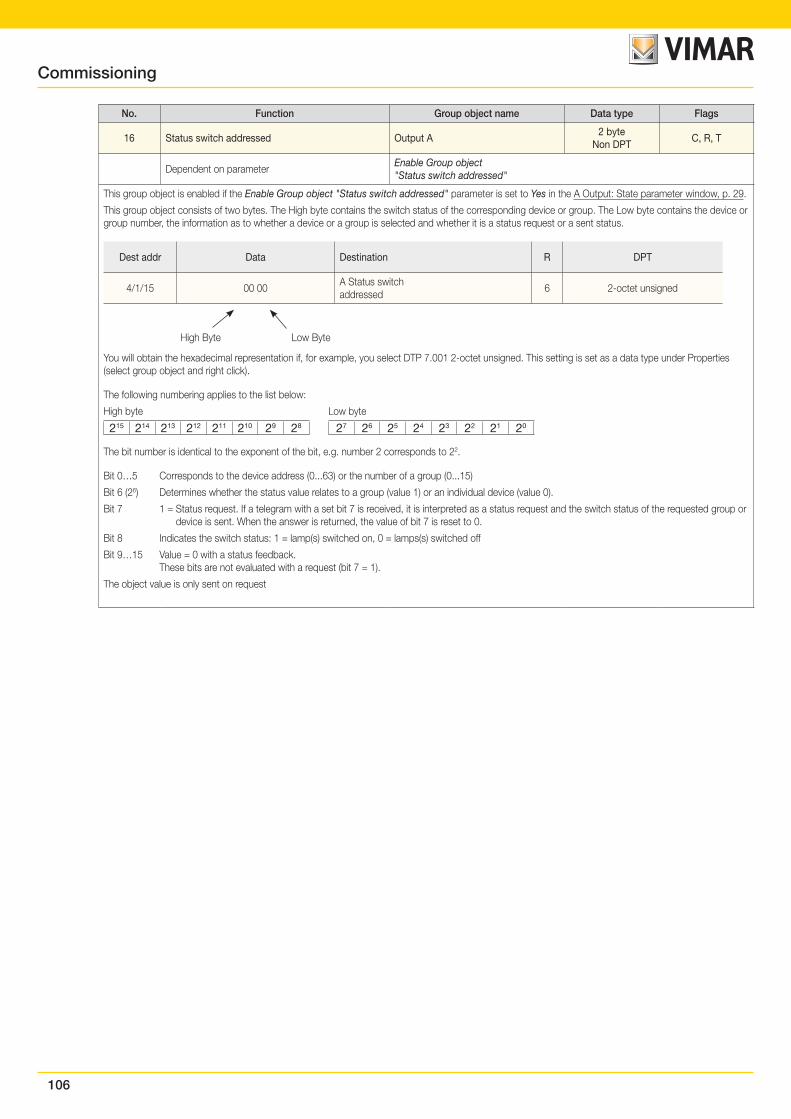
106
No. Function Group object name Data type Flags
16 Status switch addressed Output A2 byte
Non DPTC, R, T
Dependent on parameterEnable Group object "Status switch addressed"
This group object is enabled if the Enable Group object "Status switch addressed" parameter is set to Yes in the A Output: State parameter window, p. 29.
This group object consists of two bytes. The High byte contains the switch status of the corresponding device or group. The Low byte contains the device or group number, the information as to whether a device or a group is selected and whether it is a status request or a sent status.
Dest addr Data Destination R DPT
4/1/15 00 00A Status switch addressed
6 2-octet unsigned
High Byte Low Byte
You will obtain the hexadecimal representation if, for example, you select DTP 7.001 2-octet unsigned. This setting is set as a data type under Properties (select group object and right click).
The following numbering applies to the list below:
High byte Low byte
215 214 213 212 211 210 29 28 27 26 25 24 23 22 21 20
The bit number is identical to the exponent of the bit, e.g. number 2 corresponds to 22.
Bit 0…5 Corresponds to the device address (0...63) or the number of a group (0...15)
Bit 6 (26) Determines whether the status value relates to a group (value 1) or an individual device (value 0).
Bit 7 1 = Status request. If a telegram with a set bit 7 is received, it is interpreted as a status request and the switch status of the requested group or device is sent. When the answer is returned, the value of bit 7 is reset to 0.
Bit 8 Indicates the switch status: 1 = lamp(s) switched on, 0 = lamps(s) switched off
Bit 9…15 Value = 0 with a status feedback. These bits are not evaluated with a request (bit 7 = 1).
The object value is only sent on request
Commissioning
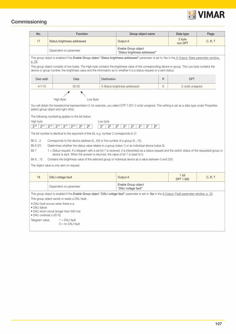
107
No. Function Group object name Data type Flags
17 Status brightness addressed Output A2 byte
non DPTC, R, T
Dependent on parameterEnable Group object "Status brightness addressed"
This group object is enabled if the Enable Group object "Status brightness addressed" parameter is set to Yes in the A Output: State parameter window, p. 29.
This group object consists of two bytes. The High byte contains the brightness value of the corresponding device or group. The Low byte contains the device or group number, the brightness value and the information as to whether it is a status request or a sent status.
Dest addr Data Destination R DPT
4/1/15 00 00 A Status brightness addressed 6 2-octet unsigned
High Byte Low Byte
You will obtain the hexadecimal representation if, for example, you select DTP 7.001 2 octet unsigned. This setting is set as a data type under Properties (select group object and right click).
The following numbering applies to the list below:
High byte Low byte
215 214 213 212 211 210 29 28 27 26 25 24 23 22 21 20
The bit number is identical to the exponent of the bit, e.g. number 2 corresponds to 22.
Bit 0…5 Corresponds to the device address (0...63) or the number of a group (0...15).
Bit 6 (26) Determines whether the status value relates to a group (value 1) or an individual device (value 0).
Bit 7 1 = Status request. If a telegram with a set bit 7 is received, it is interpreted as a status request and the switch status of the requested group or device is sent. When the answer is returned, the value of bit 7 is reset to 0.
Bit 8…15 Contains the brightness value of the selected group or individual device as a value between 0 and 255.
The object value is only sent on request.
18 DALI voltage fault Output A1 bit
DPT 1.005C, R, T
Dependent on parameterEnable Group object "DALI voltage fault"
This group object is enabled if the Enable Group object "DALI voltage fault" parameter is set to Yes in the A Output: Fault parameter window, p. 32.
This group object sends or reads a DALI fault.
A DALI fault occurs when there is a:• DALI failure• DALI short-circuit (longer than 500 ms)• DALI overload (>30 V))
Telegram value: 1 = DALI fault 0 = no DALI fault
Commissioning
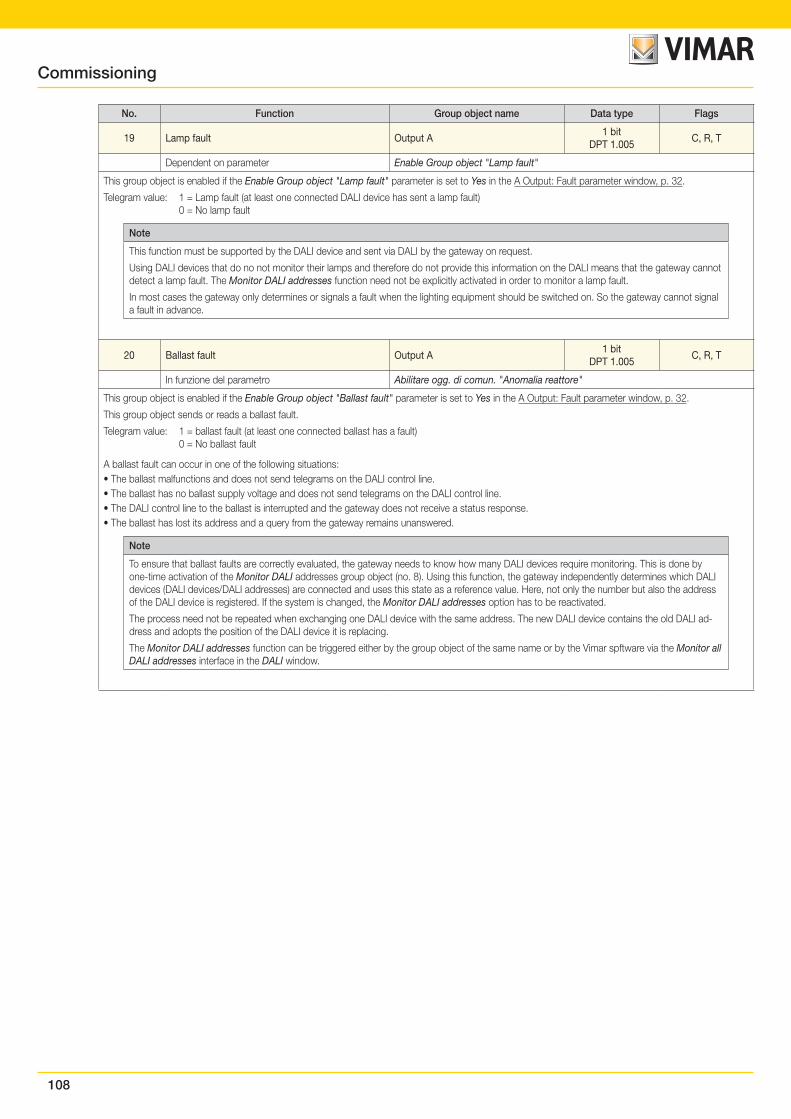
108
No. Function Group object name Data type Flags
19 Lamp fault Output A1 bit
DPT 1.005C, R, T
Dependent on parameter Enable Group object "Lamp fault"
This group object is enabled if the Enable Group object "Lamp fault" parameter is set to Yes in the A Output: Fault parameter window, p. 32.
Telegram value: 1 = Lamp fault (at least one connected DALI device has sent a lamp fault) 0 = No lamp fault
Note
This function must be supported by the DALI device and sent via DALI by the gateway on request.
Using DALI devices that do no not monitor their lamps and therefore do not provide this information on the DALI means that the gateway cannot detect a lamp fault. The Monitor DALI addresses function need not be explicitly activated in order to monitor a lamp fault.
In most cases the gateway only determines or signals a fault when the lighting equipment should be switched on. So the gateway cannot signal a fault in advance.
20 Ballast fault Output A1 bit
DPT 1.005C, R, T
In funzione del parametro Abilitare ogg. di comun. "Anomalia reattore"
This group object is enabled if the Enable Group object "Ballast fault" parameter is set to Yes in the A Output: Fault parameter window, p. 32.
This group object sends or reads a ballast fault.
Telegram value: 1 = ballast fault (at least one connected ballast has a fault) 0 = No ballast fault
A ballast fault can occur in one of the following situations:• The ballast malfunctions and does not send telegrams on the DALI control line.• The ballast has no ballast supply voltage and does not send telegrams on the DALI control line.• The DALI control line to the ballast is interrupted and the gateway does not receive a status response.• The ballast has lost its address and a query from the gateway remains unanswered.
Note
To ensure that ballast faults are correctly evaluated, the gateway needs to know how many DALI devices require monitoring. This is done by one-time activation of the Monitor DALI addresses group object (no. 8). Using this function, the gateway independently determines which DALI devices (DALI devices/DALI addresses) are connected and uses this state as a reference value. Here, not only the number but also the address of the DALI device is registered. If the system is changed, the Monitor DALI addresses option has to be reactivated.
The process need not be repeated when exchanging one DALI device with the same address. The new DALI device contains the old DALI ad-dress and adopts the position of the DALI device it is replacing.
The Monitor DALI addresses function can be triggered either by the group object of the same name or by the Vimar spftware via the Monitor all DALI addresses interface in the DALI window.
Commissioning
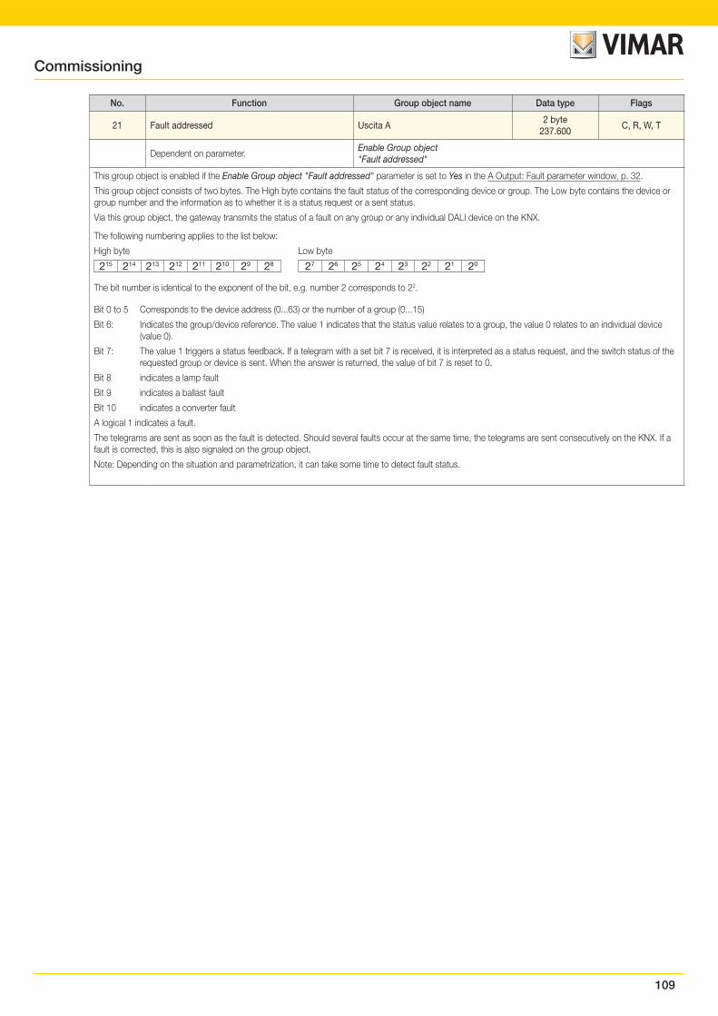
109
No. Function Group object name Data type Flags
21 Fault addressed Uscita A2 byte
237.600C, R, W, T
Dependent on parameter.Enable Group object "Fault addressed"
This group object is enabled if the Enable Group object "Fault addressed" parameter is set to Yes in the A Output: Fault parameter window, p. 32.
This group object consists of two bytes. The High byte contains the fault status of the corresponding device or group. The Low byte contains the device or group number and the information as to whether it is a status request or a sent status.
Via this group object, the gateway transmits the status of a fault on any group or any individual DALI device on the KNX.
The following numbering applies to the list below:
High byte Low byte
215 214 213 212 211 210 29 28 27 26 25 24 23 22 21 20
The bit number is identical to the exponent of the bit, e.g. number 2 corresponds to 22.
Bit 0 to 5 Corresponds to the device address (0...63) or the number of a group (0...15)
Bit 6: Indicates the group/device reference. The value 1 indicates that the status value relates to a group, the value 0 relates to an individual device (value 0).
Bit 7: The value 1 triggers a status feedback. If a telegram with a set bit 7 is received, it is interpreted as a status request, and the switch status of the requested group or device is sent. When the answer is returned, the value of bit 7 is reset to 0.
Bit 8 indicates a lamp fault
Bit 9 indicates a ballast fault
Bit 10 indicates a converter fault
A logical 1 indicates a fault.
The telegrams are sent as soon as the fault is detected. Should several faults occur at the same time, the telegrams are sent consecutively on the KNX. If a fault is corrected, this is also signaled on the group object.
Note: Depending on the situation and parametrization, it can take some time to detect fault status.
Commissioning
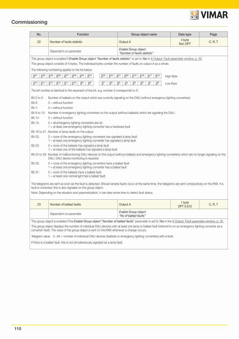
110
No. Function Group object name Data type Flags
22 Number of faults statistic Output A4 byte
Non DPTC, R, T
Dependent on parameterEnable Group object "Number of faults statistic"
This group object is enabled if Enable Group object "Number of faults statistic" is set to Yes in A Output: Fault parameter window, p. 32.
This group object consists of 4 bytes. The individual bytes contain the number of faults on output A as a whole.
The following numbering applies to the list below:
231 230 229 228 227 226 225 224 223 222 221 220 219 218 217 216
High Byte
215 214 213 212 211 210 29 28 27 26 25 24 23 22 21 20
Low Byte
The bit number is identical to the exponent of the bit, e.g. number 2 corresponds to 22.
Bit 0 to 5: Number of ballasts on the output which are currently signaling on the DALI (without emergency lighting converters)
Bit 6: 0 = without function
Bit 7: 0 = without function
Bit 8 to 13: Number of emergency lighting converters on the output (without ballasts) which are signaling the DALI.
Bit 14: 0 = without function
Bit 15: 0 = all emergency lighting converters are ok. 1 = at least one emergency lighting converter has a hardware fault
Bit 16 to 21: Number of lamp faults on the output
Bit 22: 0 = none of the emergency lighting converters has signaled a lamp fault 1 = at least one emergency lighting converter has signaled a lamp fault
Bit 23: 0 = none of the ballasts has signaled a lamp fault 1 = at least one of the ballasts has signaled a lamp fault
Bit 24 to 29: Number of malfunctioning DALI devices on the output (without ballasts and emergency lighting converters) which are no longer signaling on the DALI. DALI device monitoring is required.
Bit 30: 0 = none of the emergency lighting converters have a ballast fault 1 = at least one emergency lighting converter has a ballast fault
Bit 31: 0 = none of the ballasts have a ballast fault. 1 = at least one normal light has a ballast fault.
The telegrams are sent as soon as the fault is detected. Should several faults occur at the same time, the telegrams are sent consecutively on the KNX. If a fault is corrected, this is also signaled on the group object.
Note: Depending on the situation and parametrization, it can take some time to detect fault status.
23 Number of ballast faults Output A1 byte
DPT 5.010C, R, T
Dependent on parameterEnable Group object "No of ballast faults"
This group object is enabled if the Enable Group object "Number of ballast faults" parameter is set to Yes in the A Output: Fault parameter window, p. 32.
This group object displays the number of individual DALI devices with at least one lamp or ballast fault (referred to on an emergency lighting converter as a converter fault). The value of the group object is sent on the KNX whenever a change occurs.
Telegram value: 0...64 = number of individual DALI devices (ballasts or emergency lighting converters) with a fault.
If there is a ballast fault, this is not simultaneously signaled as a lamp fault.
Commissioning
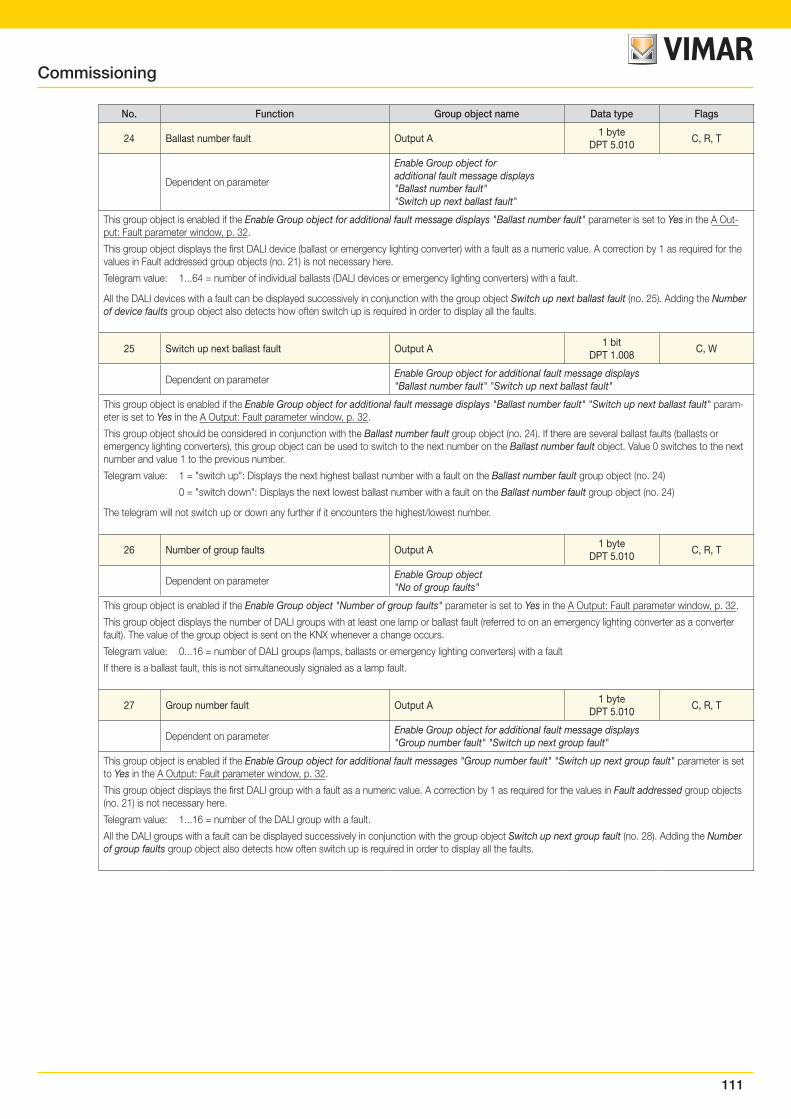
111
No. Function Group object name Data type Flags
24 Ballast number fault Output A1 byte
DPT 5.010C, R, T
Dependent on parameter
Enable Group object for additional fault message displays "Ballast number fault" "Switch up next ballast fault"
This group object is enabled if the Enable Group object for additional fault message displays "Ballast number fault" parameter is set to Yes in the A Out-put: Fault parameter window, p. 32.
This group object displays the first DALI device (ballast or emergency lighting converter) with a fault as a numeric value. A correction by 1 as required for the values in Fault addressed group objects (no. 21) is not necessary here.
Telegram value: 1...64 = number of individual ballasts (DALI devices or emergency lighting converters) with a fault.
All the DALI devices with a fault can be displayed successively in conjunction with the group object Switch up next ballast fault (no. 25). Adding the Number of device faults group object also detects how often switch up is required in order to display all the faults.
25 Switch up next ballast fault Output A1 bit
DPT 1.008C, W
Dependent on parameterEnable Group object for additional fault message displays "Ballast number fault" "Switch up next ballast fault"
This group object is enabled if the Enable Group object for additional fault message displays "Ballast number fault" "Switch up next ballast fault" param-eter is set to Yes in the A Output: Fault parameter window, p. 32.
This group object should be considered in conjunction with the Ballast number fault group object (no. 24). If there are several ballast faults (ballasts or emergency lighting converters), this group object can be used to switch to the next number on the Ballast number fault object. Value 0 switches to the next number and value 1 to the previous number.
Telegram value: 1 = "switch up": Displays the next highest ballast number with a fault on the Ballast number fault group object (no. 24)
0 = "switch down": Displays the next lowest ballast number with a fault on the Ballast number fault group object (no. 24)
The telegram will not switch up or down any further if it encounters the highest/lowest number.
26 Number of group faults Output A1 byte
DPT 5.010C, R, T
Dependent on parameterEnable Group object "No of group faults"
This group object is enabled if the Enable Group object "Number of group faults" parameter is set to Yes in the A Output: Fault parameter window, p. 32.
This group object displays the number of DALI groups with at least one lamp or ballast fault (referred to on an emergency lighting converter as a converter fault). The value of the group object is sent on the KNX whenever a change occurs.
Telegram value: 0...16 = number of DALI groups (lamps, ballasts or emergency lighting converters) with a fault
If there is a ballast fault, this is not simultaneously signaled as a lamp fault.
27 Group number fault Output A1 byte
DPT 5.010C, R, T
Dependent on parameterEnable Group object for additional fault message displays "Group number fault" "Switch up next group fault"
This group object is enabled if the Enable Group object for additional fault messages "Group number fault" "Switch up next group fault" parameter is set to Yes in the A Output: Fault parameter window, p. 32.
This group object displays the first DALI group with a fault as a numeric value. A correction by 1 as required for the values in Fault addressed group objects (no. 21) is not necessary here.
Telegram value: 1...16 = number of the DALI group with a fault.
All the DALI groups with a fault can be displayed successively in conjunction with the group object Switch up next group fault (no. 28). Adding the Number of group faults group object also detects how often switch up is required in order to display all the faults.
Commissioning

112
No. Function Group object name Data type Flags
28 Switch up next group fault Output A1 bit
DPT 1.008C, W
Dependent on parameterEnable Group object for additional fault message displays "Group number fault" "Switch up next group fault"
This group object is enabled if the Enable Group object for additional fault messages "Group number fault" "Switch up next group fault" parameter is set to Yes in the A Output: Fault parameter window, p. 32.
This group object should be considered in conjunction with the Group number fault group object (no. 27). If there are several group faults, this group object can be used to switch to the next number on the Group number fault object. Value 0 switches to the next number and value 1 to the previous number.
Telegram value: 1 = "switch up": Displays the next highest group number with a fault on the Group number fault group object (no. 27).)
0 = "switch down": Displays the next lowest group number with a fault on the Group number fault group object (no. 27).
The telegram will not switch up or down any further if it encounters the highest/lowest number.
29 Acknowledge fault messages/Status Output A1 bit
DPT 1.015C, R, W, T
Dependent on parameterAcknowledge fault messages Enable Group object "Acknowledge fault messages/Status"
This group object is enabled if the Acknowledge fault messages Enable Group object "Acknowledge fault messages/Status" parameter is set to Yes in the A Output: Fault parameter window, p. 32.
This group object is used to reset a DALI output fault. The fault may be a lamp, ballast or emergency lighting converter fault relating to individual devices or a DALI group. The fault is only reset after acknowledgement if it has been corrected.
Telegram value: 0 = No function
1 = Reset fault messages
30 Disable fault messages/Status Output A1 bit
DPT 1.003C, R, W, T
Dependent on parameterEnable Group object "Disable fault messages/Status"
This group object is enabled if the Enable Group object "Acknowledge fault messages/Status" parameter is set to Yes in the A Output: Fault parameter window, p. 32.
This group object can be used to disable the fault messages (lamp, ballast and converter faults) for the DALI output. The gateway will continue checking fault messages even when the messages themselves are disabled.
During the inhibit, the faults are evaluated but not sent on the KNX. The values of the group objects are also not updated.
Disabling fault messages minimizes system latency by reducing the KNX load.
When fault messages are enabled, all faults are sent in accordance with their parametrization. If a fault still exists after fault messages are enabled, this fault is recorded and the information is sent on the KNX in accordance with the parametrization.
Telegram value: 1 = disables fault messages (lamp, ballast and converter fault) 0 = enables fault messages (lamp, ballast and converter fault)
Note
This function can be useful e.g. for systems with emergency lighting applications for daily lamp checks which disconnect the lamps from the DALI control line, and thus from the DALI master (gateway). In this case, the gateway detects the loss of the DALI device and sends a ballast fault even though this is a normal operating state. If fault messages are disabled before disconnection from the DALI control line, no fault is signaled on the gateway. Operation can continue as normal. When the lamp checks are complete, normal monitoring can be reactivated via the Disable fault messages group object.
Commissioning
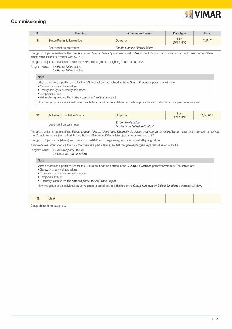
113
No. Function Group object name Data type Flags
31 Status Partial failure active Output A1 bit
DPT 1.010C, R, T
Dependent on parameter Enable function "Partial failure"
This group object is enabled if the Enable function "Partial failure" parameter is set to Yes in the A Output: Functions (Turn off brightness/Burn-in/Slave offset/Partial failure) parameter window, p. 37.
This group object sends information on the KNX indicating a partial lighting failure on output A.
Telegram value: 1 = Partial failure active 0 = Partial failure inactive
Note
What constitutes a partial failure for the DALI output can be defined in the A Output Functions parameter window.• Gateway supply voltage failure• Emergency lights in emergency mode• Lamp/ballast fault• Externally signaled via the Activate partial failure/Status object
How the group or an individual ballast reacts to a partial failure is defined in the Group functions or Ballast functions parameter window.
31 Activate partial failure/Status Output A1 bit
DPT 1.010C, R, W, T
Dependent on parameterExternally via object"Activate partial failure/Status"
This group object is enabled if the Enable function "Partial failure" and Externally via object "Activate partial failure/Status" parameters are both set to Yes in A Output: Functions (Turn off brightness/Burn-in/Slave offset/Partial failure) parameter window, p. 37.
This group object sends (status) information on the KNX from the gateway, indicating a partial lighting failure.
It also receives information via the KNX that there is a partial failure, so that the gateway triggers a partial failure on output A..
Telegram value: 1 = Activate partial failure 0 = Deactivate partial failure
Note
What constitutes a partial failure for the DALI output can be defined in the A Output Functions parameter window. The criteria are:• Gateway supply voltage failure• Emergency lights in emergency mode• Lamp/ballast fault• Externally signaled via the Activate partial failure/Status object
How the group or an individual ballast reacts to a partial failure is defined in the Group functions or Ballast functions parameter window.
32 blank
Group object is not assigned.
Commissioning
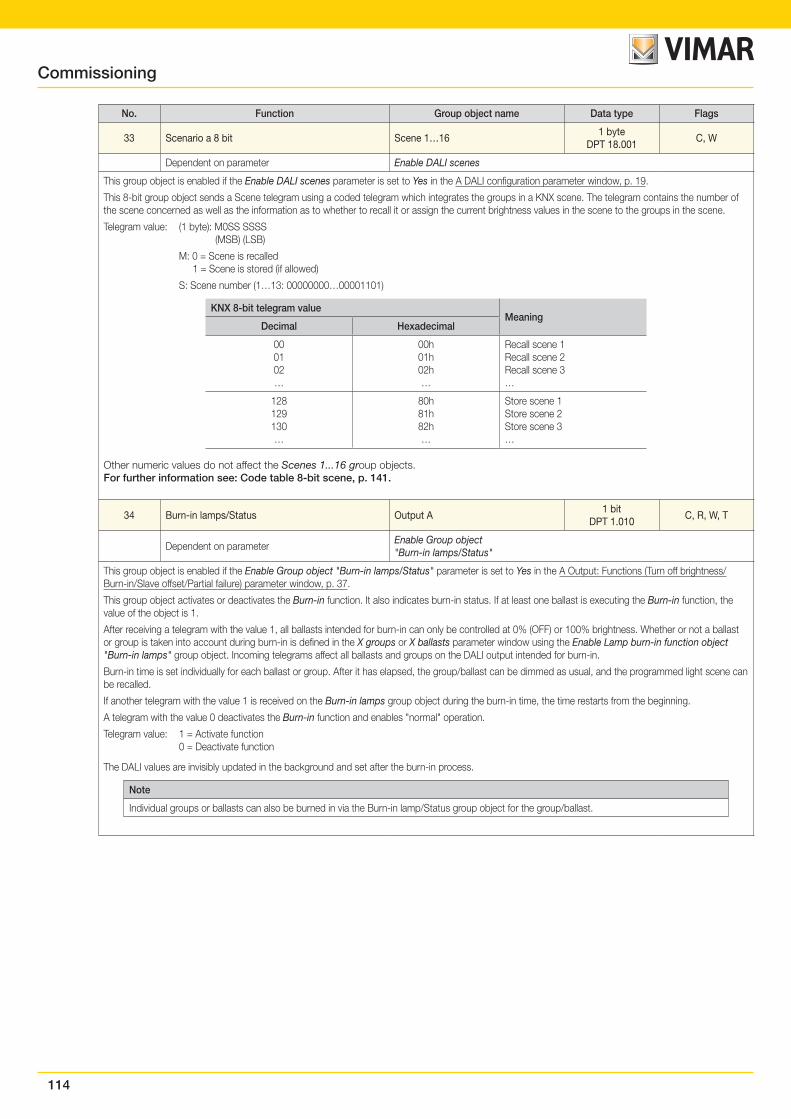
114
No. Function Group object name Data type Flags
33 Scenario a 8 bit Scene 1…161 byte
DPT 18.001C, W
Dependent on parameter Enable DALI scenes
This group object is enabled if the Enable DALI scenes parameter is set to Yes in the A DALI configuration parameter window, p. 19.
This 8-bit group object sends a Scene telegram using a coded telegram which integrates the groups in a KNX scene. The telegram contains the number of the scene concerned as well as the information as to whether to recall it or assign the current brightness values in the scene to the groups in the scene.
Telegram value: (1 byte): M0SS SSSS (MSB) (LSB)
M: 0 = Scene is recalled 1 = Scene is stored (if allowed)
S: Scene number (1…13: 00000000…00001101)
KNX 8-bit telegram valueMeaning
Decimal Hexadecimal
000102…
00h01h02h…
Recall scene 1Recall scene 2Recall scene 3…
128129130…
80h81h82h…
Store scene 1Store scene 2Store scene 3…
Other numeric values do not affect the Scenes 1...16 group objects.For further information see: Code table 8-bit scene, p. 141.
34 Burn-in lamps/Status Output A1 bit
DPT 1.010C, R, W, T
Dependent on parameterEnable Group object "Burn-in lamps/Status"
This group object is enabled if the Enable Group object "Burn-in lamps/Status" parameter is set to Yes in the A Output: Functions (Turn off brightness/Burn-in/Slave offset/Partial failure) parameter window, p. 37.
This group object activates or deactivates the Burn-in function. It also indicates burn-in status. If at least one ballast is executing the Burn-in function, the value of the object is 1.
After receiving a telegram with the value 1, all ballasts intended for burn-in can only be controlled at 0% (OFF) or 100% brightness. Whether or not a ballast or group is taken into account during burn-in is defined in the X groups or X ballasts parameter window using the Enable Lamp burn-in function object "Burn-in lamps" group object. Incoming telegrams affect all ballasts and groups on the DALI output intended for burn-in.
Burn-in time is set individually for each ballast or group. After it has elapsed, the group/ballast can be dimmed as usual, and the programmed light scene can be recalled.
If another telegram with the value 1 is received on the Burn-in lamps group object during the burn-in time, the time restarts from the beginning.
A telegram with the value 0 deactivates the Burn-in function and enables "normal" operation.
Telegram value: 1 = Activate function 0 = Deactivate function
The DALI values are invisibly updated in the background and set after the burn-in process.
Note
Individual groups or ballasts can also be burned in via the Burn-in lamp/Status group object for the group/ballast.
Commissioning
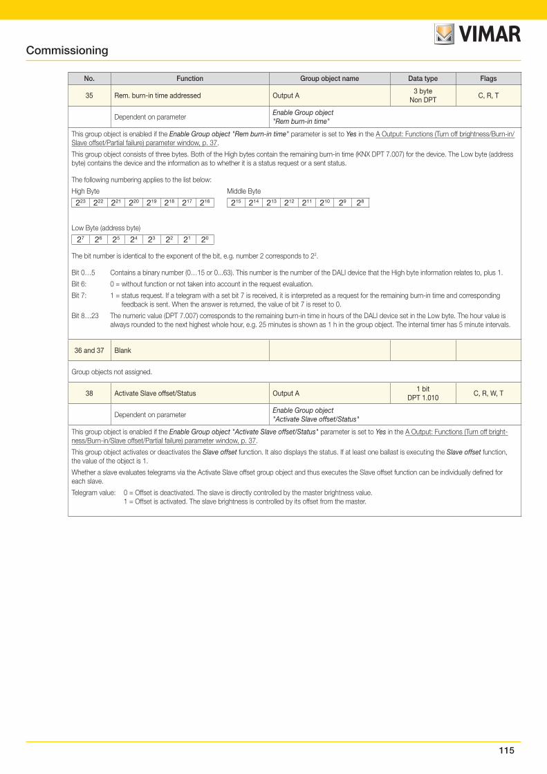
115
No. Function Group object name Data type Flags
35 Rem. burn-in time addressed Output A3 byte
Non DPTC, R, T
Dependent on parameterEnable Group object "Rem burn-in time"
This group object is enabled if the Enable Group object "Rem burn-in time" parameter is set to Yes in the A Output: Functions (Turn off brightness/Burn-in/Slave offset/Partial failure) parameter window, p. 37.
This group object consists of three bytes. Both of the High bytes contain the remaining burn-in time (KNX DPT 7.007) for the device. The Low byte (address byte) contains the device and the information as to whether it is a status request or a sent status.
The following numbering applies to the list below:
High Byte Middle Byte
223 222 221 220 219 218 217 216 215 214 213 212 211 210 29 28
Low Byte (address byte)
27 26 25 24 23 22 21 20
The bit number is identical to the exponent of the bit, e.g. number 2 corresponds to 22.
Bit 0…5 Contains a binary number (0…15 or 0...63). This number is the number of the DALI device that the High byte information relates to, plus 1.
Bit 6: 0 = without function or not taken into account in the request evaluation.
Bit 7: 1 = status request. If a telegram with a set bit 7 is received, it is interpreted as a request for the remaining burn-in time and corresponding feedback is sent. When the answer is returned, the value of bit 7 is reset to 0.
Bit 8…23 The numeric value (DPT 7.007) corresponds to the remaining burn-in time in hours of the DALI device set in the Low byte. The hour value is always rounded to the next highest whole hour, e.g. 25 minutes is shown as 1 h in the group object. The internal timer has 5 minute intervals.
36 and 37 Blank
Group objects not assigned.
38 Activate Slave offset/Status Output A1 bit
DPT 1.010C, R, W, T
Dependent on parameterEnable Group object "Activate Slave offset/Status"
This group object is enabled if the Enable Group object "Activate Slave offset/Status" parameter is set to Yes in the A Output: Functions (Turn off bright-ness/Burn-in/Slave offset/Partial failure) parameter window, p. 37.
This group object activates or deactivates the Slave offset function. It also displays the status. If at least one ballast is executing the Slave offset function, the value of the object is 1.
Whether a slave evaluates telegrams via the Activate Slave offset group object and thus executes the Slave offset function can be individually defined for each slave.
Telegram value: 0 = Offset is deactivated. The slave is directly controlled by the master brightness value. 1 = Offset is activated. The slave brightness is controlled by its offset from the master.
Commissioning
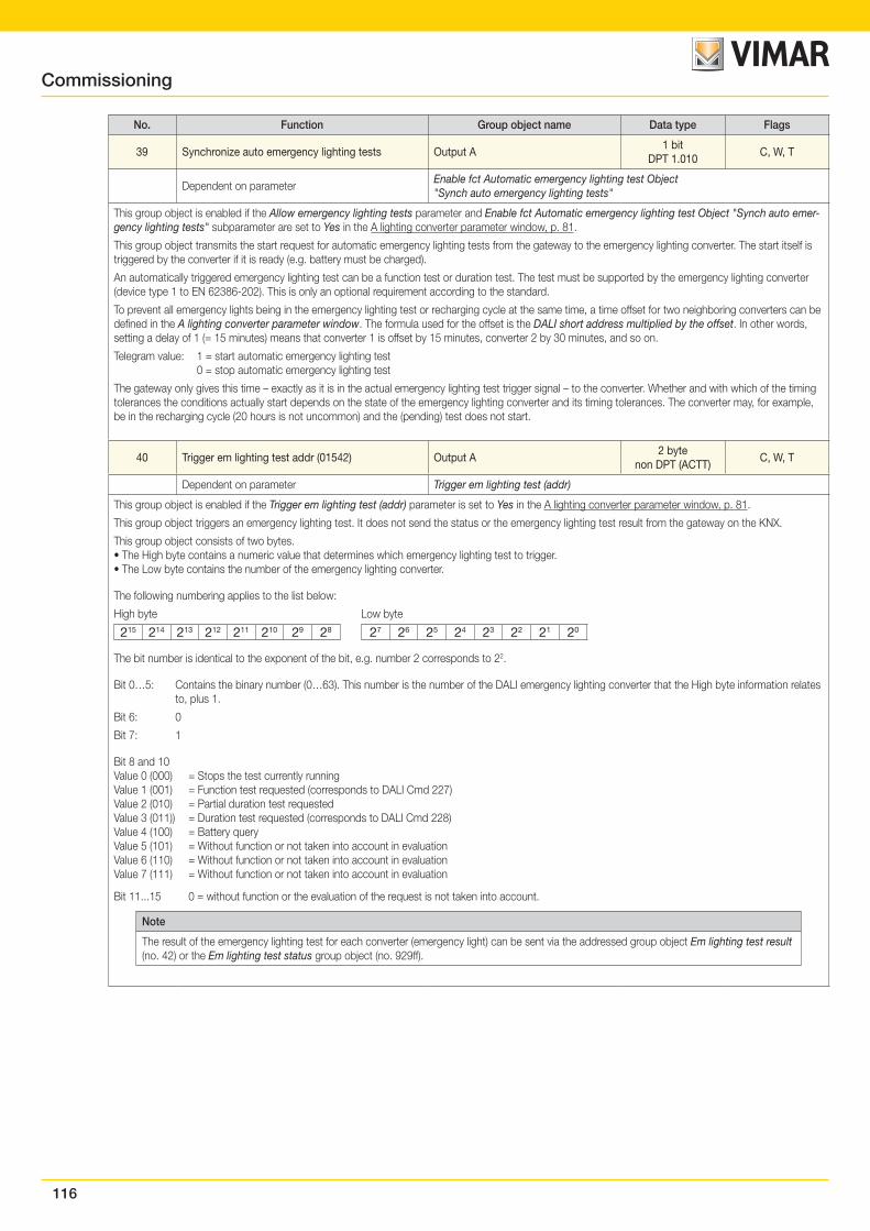
116
No. Function Group object name Data type Flags
39 Synchronize auto emergency lighting tests Output A1 bit
DPT 1.010C, W, T
Dependent on parameterEnable fct Automatic emergency lighting test Object "Synch auto emergency lighting tests"
This group object is enabled if the Allow emergency lighting tests parameter and Enable fct Automatic emergency lighting test Object "Synch auto emer-gency lighting tests" subparameter are set to Yes in the A lighting converter parameter window, p. 81.
This group object transmits the start request for automatic emergency lighting tests from the gateway to the emergency lighting converter. The start itself is triggered by the converter if it is ready (e.g. battery must be charged).
An automatically triggered emergency lighting test can be a function test or duration test. The test must be supported by the emergency lighting converter (device type 1 to EN 62386-202). This is only an optional requirement according to the standard.
To prevent all emergency lights being in the emergency lighting test or recharging cycle at the same time, a time offset for two neighboring converters can be defined in the A lighting converter parameter window. The formula used for the offset is the DALI short address multiplied by the offset. In other words, setting a delay of 1 (= 15 minutes) means that converter 1 is offset by 15 minutes, converter 2 by 30 minutes, and so on.
Telegram value: 1 = start automatic emergency lighting test 0 = stop automatic emergency lighting test
The gateway only gives this time – exactly as it is in the actual emergency lighting test trigger signal – to the converter. Whether and with which of the timing tolerances the conditions actually start depends on the state of the emergency lighting converter and its timing tolerances. The converter may, for example, be in the recharging cycle (20 hours is not uncommon) and the (pending) test does not start.
40 Trigger em lighting test addr (01542) Output A2 byte
non DPT (ACTT)C, W, T
Dependent on parameter Trigger em lighting test (addr)
This group object is enabled if the Trigger em lighting test (addr) parameter is set to Yes in the A lighting converter parameter window, p. 81.
This group object triggers an emergency lighting test. It does not send the status or the emergency lighting test result from the gateway on the KNX.
This group object consists of two bytes.• The High byte contains a numeric value that determines which emergency lighting test to trigger.• The Low byte contains the number of the emergency lighting converter.
The following numbering applies to the list below:
High byte Low byte
215 214 213 212 211 210 29 28 27 26 25 24 23 22 21 20
The bit number is identical to the exponent of the bit, e.g. number 2 corresponds to 22.
Bit 0…5: Contains the binary number (0…63). This number is the number of the DALI emergency lighting converter that the High byte information relates to, plus 1.
Bit 6: 0
Bit 7: 1
Bit 8 and 10 Value 0 (000) = Stops the test currently runningValue 1 (001) = Function test requested (corresponds to DALI Cmd 227)Value 2 (010) = Partial duration test requestedValue 3 (011)) = Duration test requested (corresponds to DALI Cmd 228)Value 4 (100) = Battery queryValue 5 (101) = Without function or not taken into account in evaluationValue 6 (110) = Without function or not taken into account in evaluationValue 7 (111) = Without function or not taken into account in evaluation
Bit 11...15 0 = without function or the evaluation of the request is not taken into account.
Note
The result of the emergency lighting test for each converter (emergency light) can be sent via the addressed group object Em lighting test result (no. 42) or the Em lighting test status group object (no. 929ff).
Commissioning
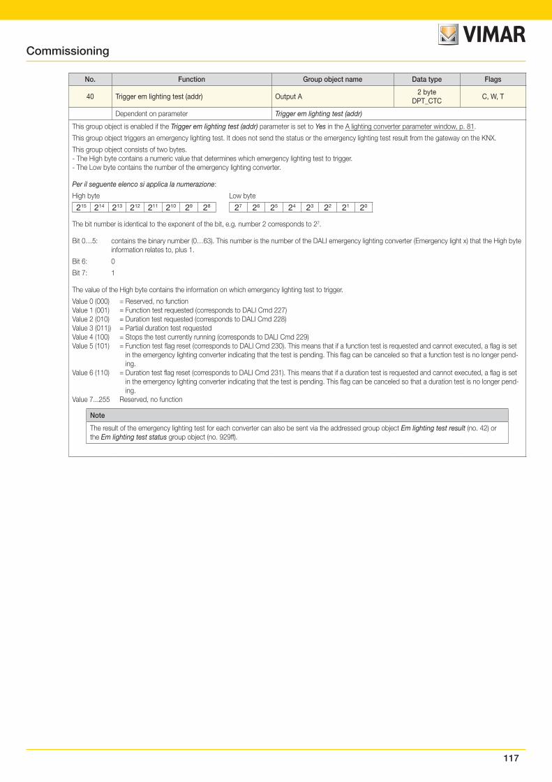
117
No. Function Group object name Data type Flags
40 Trigger em lighting test (addr) Output A2 byte
DPT_CTCC, W, T
Dependent on parameter Trigger em lighting test (addr)
This group object is enabled if the Trigger em lighting test (addr) parameter is set to Yes in the A lighting converter parameter window, p. 81.
This group object triggers an emergency lighting test. It does not send the status or the emergency lighting test result from the gateway on the KNX.
This group object consists of two bytes.- The High byte contains a numeric value that determines which emergency lighting test to trigger.- The Low byte contains the number of the emergency lighting converter.
Per il seguente elenco si applica la numerazione:
High byte Low byte
215 214 213 212 211 210 29 28 27 26 25 24 23 22 21 20
The bit number is identical to the exponent of the bit, e.g. number 2 corresponds to 22.
Bit 0…5: contains the binary number (0…63). This number is the number of the DALI emergency lighting converter (Emergency light x) that the High byte information relates to, plus 1.
Bit 6: 0
Bit 7: 1
The value of the High byte contains the information on which emergency lighting test to trigger.
Value 0 (000) = Reserved, no functionValue 1 (001) = Function test requested (corresponds to DALI Cmd 227)Value 2 (010) = Duration test requested (corresponds to DALI Cmd 228)Value 3 (011)) = Partial duration test requestedValue 4 (100) = Stops the test currently running (corresponds to DALI Cmd 229)Value 5 (101) = Function test flag reset (corresponds to DALI Cmd 230). This means that if a function test is requested and cannot executed, a flag is set
in the emergency lighting converter indicating that the test is pending. This flag can be canceled so that a function test is no longer pend-ing.
Value 6 (110) = Duration test flag reset (corresponds to DALI Cmd 231). This means that if a duration test is requested and cannot executed, a flag is set in the emergency lighting converter indicating that the test is pending. This flag can be canceled so that a duration test is no longer pend-ing.
Value 7...255 Reserved, no function
Note
The result of the emergency lighting test for each converter can also be sent via the addressed group object Em lighting test result (no. 42) or the Em lighting test status group object (no. 929ff).
Commissioning
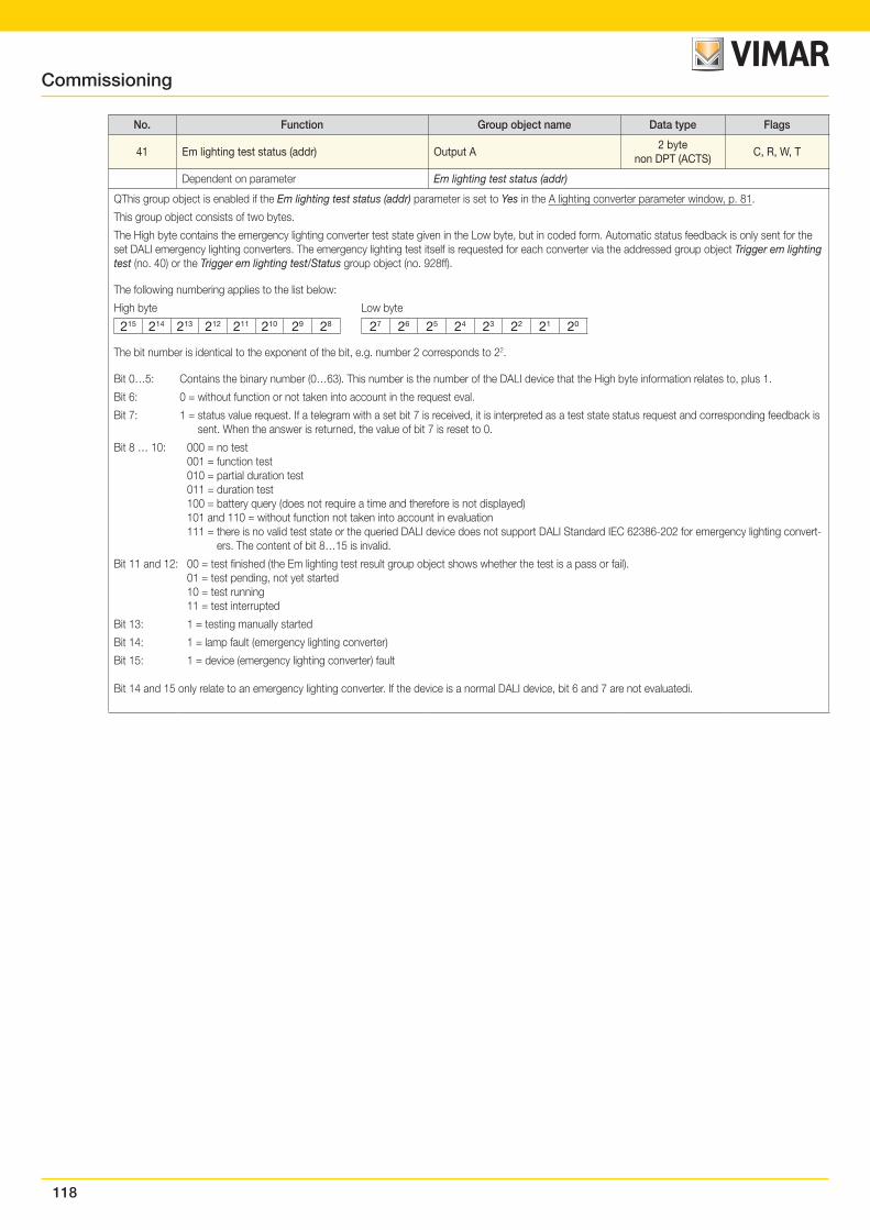
118
No. Function Group object name Data type Flags
41 Em lighting test status (addr) Output A2 byte
non DPT (ACTS)C, R, W, T
Dependent on parameter Em lighting test status (addr)
QThis group object is enabled if the Em lighting test status (addr) parameter is set to Yes in the A lighting converter parameter window, p. 81.
This group object consists of two bytes.
The High byte contains the emergency lighting converter test state given in the Low byte, but in coded form. Automatic status feedback is only sent for the set DALI emergency lighting converters. The emergency lighting test itself is requested for each converter via the addressed group object Trigger em lighting test (no. 40) or the Trigger em lighting test/Status group object (no. 928ff).
The following numbering applies to the list below:
High byte Low byte
215 214 213 212 211 210 29 28 27 26 25 24 23 22 21 20
The bit number is identical to the exponent of the bit, e.g. number 2 corresponds to 22.
Bit 0…5: Contains the binary number (0…63). This number is the number of the DALI device that the High byte information relates to, plus 1.
Bit 6: 0 = without function or not taken into account in the request eval.
Bit 7: 1 = status value request. If a telegram with a set bit 7 is received, it is interpreted as a test state status request and corresponding feedback is sent. When the answer is returned, the value of bit 7 is reset to 0.
Bit 8 … 10: 000 = no test 001 = function test 010 = partial duration test 011 = duration test 100 = battery query (does not require a time and therefore is not displayed) 101 and 110 = without function not taken into account in evaluation 111 = there is no valid test state or the queried DALI device does not support DALI Standard IEC 62386-202 for emergency lighting convert-
ers. The content of bit 8…15 is invalid.
Bit 11 and 12: 00 = test finished (the Em lighting test result group object shows whether the test is a pass or fail). 01 = test pending, not yet started 10 = test running 11 = test interrupted
Bit 13: 1 = testing manually started
Bit 14: 1 = lamp fault (emergency lighting converter)
Bit 15: 1 = device (emergency lighting converter) fault
Bit 14 and 15 only relate to an emergency lighting converter. If the device is a normal DALI device, bit 6 and 7 are not evaluatedi.
Commissioning
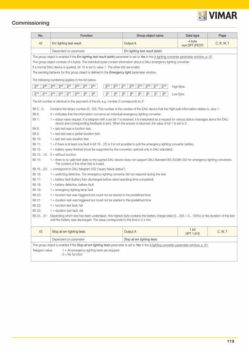
119
No. Function Group object name Data type Flags
42 Em lighting test result Output A4 byte
non DPT (FEOT)C, R, W, T
Dependent on parameter Em lighting test result (addr)
This group object is enabled if the Em lighting test result (addr) parameter is set to Yes in the A lighting converter parameter window, p. 81.
This group object consists of 4 bytes. The individual bytes contain information about a DALI emergency lighting converter.
If a normal DALI device is queried, bit 15 is set to value 1. The other bits are invalid.
The sending behavior for this group object is defined in the Emergency light parameter window.
The following numbering applies to the list below:
231 230 229 228 227 226 225 224 223 222 221 220 219 218 217 216
High Byte
215 214 213 212 211 210 29 28 27 26 25 24 23 22 21 20
Low Byte
The bit number is identical to the exponent of the bit, e.g. number 2 corresponds to 22.
Bit 0…5: Contains the binary number (0…63). This number is the number of the DALI device that the High byte information relates to, plus 1.
Bit 6: 0 = indicates that the information concerns an individual emergency lighting converter.
Bit 7: 1 = status value request. If a telegram with a set bit 7 is received, it is interpreted as a request for various status messages about the DALI device and corresponding feedback is sent. When the answer is returned, the value of bit 7 is set to 0.
Bit 8: 1 = last test was a function test.
Bit 9: 1 = last test was a partial duration test.
Bit 10: 1 = last test was duration test.
Bit 11: 1 = if there is at least one fault in bit 16…23 or it is not possible to poll the emergency lighting converter battery.
Bit 12: 1 = battery query finished (must be supported by the converter, optional only in DALI standard).
Bit 13…14: 0 = without function
Bit 15: 1 = there is no valid test state or the queried DALI device does not support DALI Standard IEC 62386-202 for emergency lighting converters. The content of the other bits is invalid.
Bit 16…23: = correspond to DALI telegram 252 ("query failure status").
Bit 16: 1 = switching defective. The emergency lighting converter did not respond during the test.
Bit 17: 1 = battery fault (battery fully discharged before rated operating time completed)
Bit 18: 1 = battery defective, battery fault
Bit 19: 1 = emergency lighting lamp fault
Bit 20: 1 = function test was triggered but could not be started in the predefined time
Bit 21: 1 = duration test was triggered but could not be started in the predefined time
Bit 22: 1 = function test fault, fail
Bit 23: 1 = duration test fault, fail
Bit 24…31: Depending which test has been undertaken, this highest byte contains the battery charge state (0…255 = 0…100%) or the duration of the test until the battery was discharged. The value corresponds to the time in 2 x min.
43 Stop all em lighting tests Output A1 bit
DPT 1.010C, W, T
Dependent on parameter Stop all em lighting tests
This group object is enabled if the Stop all em lighting tests parameter is set to Yes in the A lighting converter parameter window, p. 81.
Telegram value: 1 = All emergency lighting tests are stopped 0 = No function
Commissioning
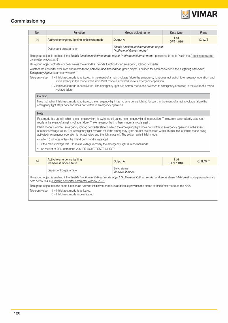
120
No. Function Group object name Data type Flags
44 Activate emergency lighting Inhibit/rest mode Output A1 bit
DPT 1.010C, W, T
Dependent on parameterEnable function Inhibit/rest mode object"Activate Inhibit/rest mode"
This group object is enabled if the Enable function Inhibit/rest mode object "Activate Inhibit/rest mode" parameter is set to Yes in the A lighting converter parameter window, p. 81.
This group object activates or deactivates the Inhibit/rest mode function for an emergency lighting converter.
Whether the converter evaluates and reacts to the Activate Inhibit/rest mode group object is defined for each converter in the A lighting converter/Emergency light x parameter window.
Telegram value: 1 = Inhibit/rest mode is activated. In the event of a mains voltage failure the emergency light does not switch to emergency operation, and if it is already in this mode when Inhibit/rest mode is activated, it exits emergency operation.
0 = Inhibit/rest mode is deactivated. The emergency light is in normal mode and switches to emergency operation in the event of a mains voltage failure.
Caution
Note that when Inhibit/rest mode is activated, the emergency light has no emergency lighting function. In the event of a mains voltage failure the emergency light stays dark and does not switch to emergency operation.
Note
Rest mode is a state in which the emergency light is switched off during its emergency lighting operation. The system automatically exits rest mode in the event of a mains voltage failure. The emergency light is then in normal mode again.
Inhibit mode is a timed emergency lighting converter state in which the emergency light does not switch to emergency operation in the event of a mains voltage failure. The emergency light remains off. If the emergency lights are not switched off within 15 minutes (of Inhibit mode being activated), emergency operation is not activated and the light stays off. The system exits Inhibit mode:
• - after 15 minutes unless the Inhibit command is repeated.
• - if the mains voltage fails. On mains voltage recovery the emergency light is in normal mode.
• - on receipt of DALI command 226 "RE-LIGHT/RESET INHIBIT".
44Activate emergency lighting Inhibit/rest mode/Status
Output A1 bit
DPT 1.010C, R, W, T
Dependent on parameterSend status Inhibit/rest mode
This group object is enabled if the Enable function Inhibit/rest mode object "Activate Inhibit/rest mode" and Send status Inhibit/rest mode parameters are both set to Yes in A lighting converter parameter window, p. 81.
This group object has the same function as Activate Inhibit/rest mode. In addition, it provides the status of Inhibit/rest mode on the KNX.
Telegram value: 1 = Inhibit/rest mode is activated. 0 = Inhibit/rest mode is deactivated.
Commissioning
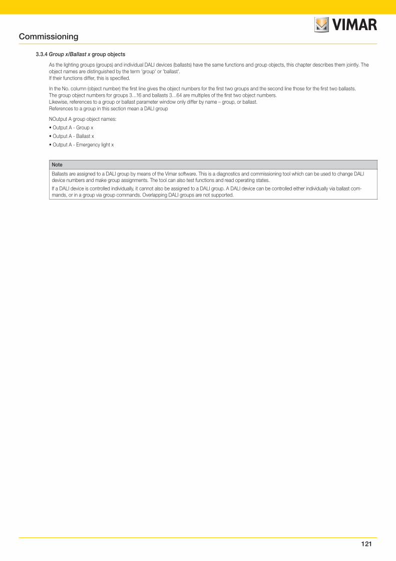
121
3.3.4 Group x/Ballast x group objects
As the lighting groups (groups) and individual DALI devices (ballasts) have the same functions and group objects, this chapter describes them jointly. The object names are distinguished by the term 'group' or 'ballast'.If their functions differ, this is specified.
In the No. column (object number) the first line gives the object numbers for the first two groups and the second line those for the first two ballasts.The group object numbers for groups 3…16 and ballasts 3…64 are multiples of the first two object numbers.Likewise, references to a group or ballast parameter window only differ by name – group, or ballast.References to a group in this section mean a DALI group
NOutput A group object names:
• Output A - Group x
• Output A - Ballast x
• Output A - Emergency light x
Note
Ballasts are assigned to a DALI group by means of the Vimar software. This is a diagnostics and commissioning tool which can be used to change DALI device numbers and make group assignments. The tool can also test functions and read operating states.
If a DALI device is controlled individually, it cannot also be assigned to a DALI group. A DALI device can be controlled either individually via ballast com-mands, or in a group via group commands. Overlapping DALI groups are not supported.
Commissioning
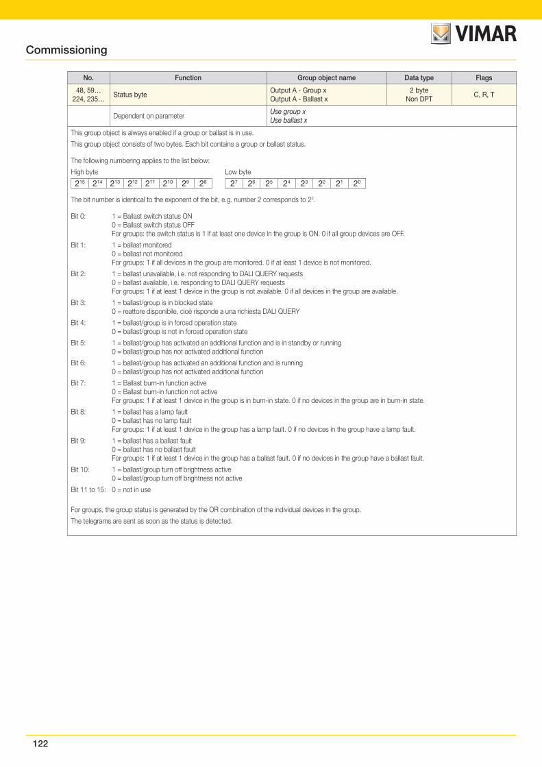
122
No. Function Group object name Data type Flags
48, 59…224, 235…
Status byteOutput A - Group xOutput A - Ballast x
2 byteNon DPT
C, R, T
Dependent on parameterUse group xUse ballast x
This group object is always enabled if a group or ballast is in use.
This group object consists of two bytes. Each bit contains a group or ballast status.
The following numbering applies to the list below:
High byte Low byte
215 214 213 212 211 210 29 28 27 26 25 24 23 22 21 20
The bit number is identical to the exponent of the bit, e.g. number 2 corresponds to 22.
Bit 0: 1 = Ballast switch status ON 0 = Ballast switch status OFF For groups: the switch status is 1 if at least one device in the group is ON. 0 if all group devices are OFF.
Bit 1: 1 = ballast monitored 0 = ballast not monitored For groups: 1 if all devices in the group are monitored. 0 if at least 1 device is not monitored.
Bit 2: 1 = ballast unavailable, i.e. not responding to DALI QUERY requests 0 = ballast available, i.e. responding to DALI QUERY requests For groups: 1 if at least 1 device in the group is not available. 0 if all devices in the group are available.
Bit 3: 1 = ballast/group is in blocked state 0 = reattore disponibile, cioè risponde a una richiesta DALI QUERY
Bit 4: 1 = ballast/group is in forced operation state 0 = ballast/group is not in forced operation state
Bit 5: 1 = ballast/group has activated an additional function and is in standby or running 0 = ballast/group has not activated additional function
Bit 6: 1 = ballast/group has activated an additional function and is running 0 = ballast/group has not activated additional function
Bit 7: 1 = Ballast burn-in function active 0 = Ballast burn-in function not active For groups: 1 if at least 1 device in the group is in burn-in state. 0 if no devices in the group are in burn-in state.
Bit 8: 1 = ballast has a lamp fault 0 = ballast has no lamp fault For groups: 1 if at least 1 device in the group has a lamp fault. 0 if no devices in the group have a lamp fault.
Bit 9: 1 = ballast has a ballast fault 0 = ballast has no ballast fault For groups: 1 if at least 1 device in the group has a ballast fault. 0 if no devices in the group have a ballast fault.
Bit 10: 1 = ballast/group turn off brightness active 0 = ballast/group turn off brightness not active
Bit 11 to 15: 0 = not in use
For groups, the group status is generated by the OR combination of the individual devices in the group.
The telegrams are sent as soon as the status is detected.
Commissioning
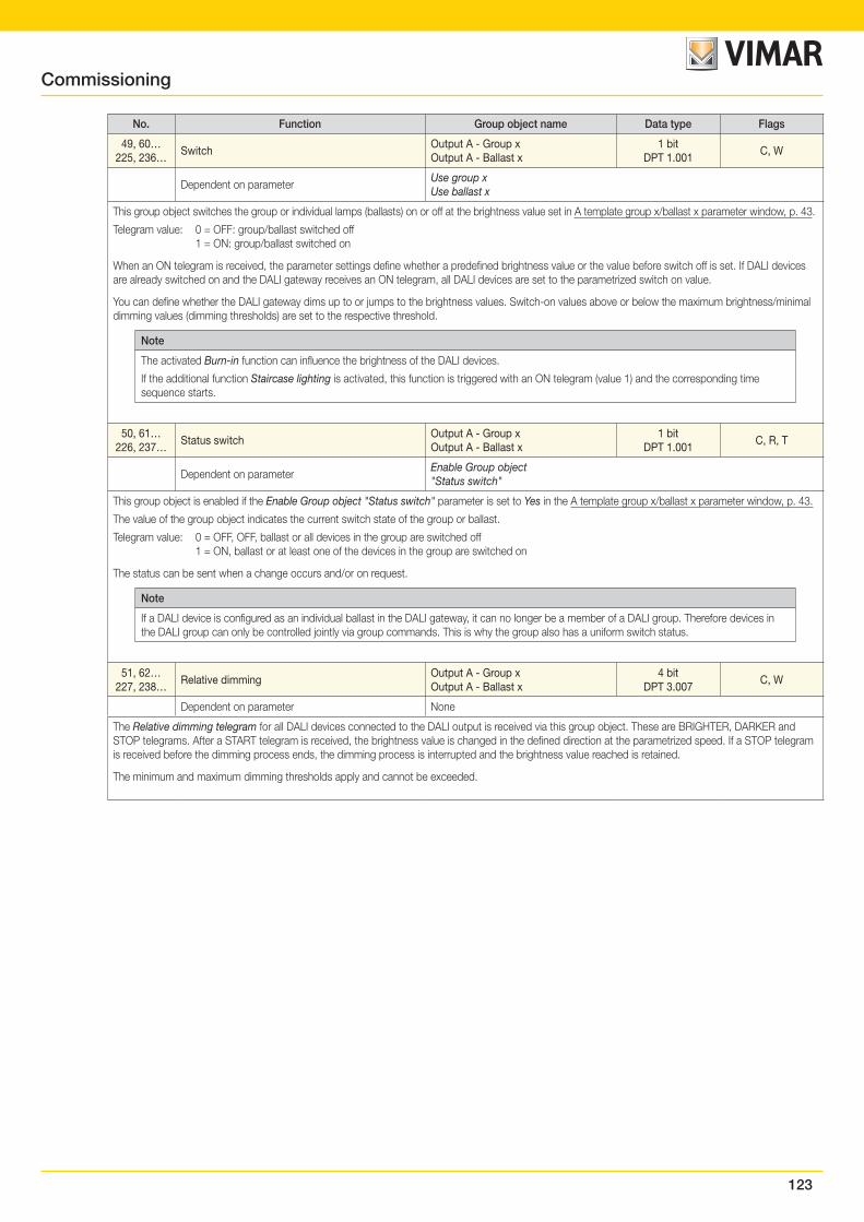
123
No. Function Group object name Data type Flags
49, 60…225, 236…
SwitchOutput A - Group xOutput A - Ballast x
1 bitDPT 1.001
C, W
Dependent on parameterUse group xUse ballast x
This group object switches the group or individual lamps (ballasts) on or off at the brightness value set in A template group x/ballast x parameter window, p. 43.
Telegram value: 0 = OFF: group/ballast switched off 1 = ON: group/ballast switched on
When an ON telegram is received, the parameter settings define whether a predefined brightness value or the value before switch off is set. If DALI devices are already switched on and the DALI gateway receives an ON telegram, all DALI devices are set to the parametrized switch on value.
You can define whether the DALI gateway dims up to or jumps to the brightness values. Switch-on values above or below the maximum brightness/minimal dimming values (dimming thresholds) are set to the respective threshold.
Note
The activated Burn-in function can influence the brightness of the DALI devices.
If the additional function Staircase lighting is activated, this function is triggered with an ON telegram (value 1) and the corresponding time sequence starts.
50, 61…226, 237…
Status switchOutput A - Group xOutput A - Ballast x
1 bitDPT 1.001
C, R, T
Dependent on parameterEnable Group object "Status switch"
This group object is enabled if the Enable Group object "Status switch" parameter is set to Yes in the A template group x/ballast x parameter window, p. 43.
The value of the group object indicates the current switch state of the group or ballast.
Telegram value: 0 = OFF, OFF, ballast or all devices in the group are switched off 1 = ON, ballast or at least one of the devices in the group are switched on
The status can be sent when a change occurs and/or on request.
Note
If a DALI device is configured as an individual ballast in the DALI gateway, it can no longer be a member of a DALI group. Therefore devices in the DALI group can only be controlled jointly via group commands. This is why the group also has a uniform switch status.
51, 62…227, 238…
Relative dimmingOutput A - Group xOutput A - Ballast x
4 bitDPT 3.007
C, W
Dependent on parameter None
The Relative dimming telegram for all DALI devices connected to the DALI output is received via this group object. These are BRIGHTER, DARKER and STOP telegrams. After a START telegram is received, the brightness value is changed in the defined direction at the parametrized speed. If a STOP telegram is received before the dimming process ends, the dimming process is interrupted and the brightness value reached is retained.
The minimum and maximum dimming thresholds apply and cannot be exceeded.
Commissioning
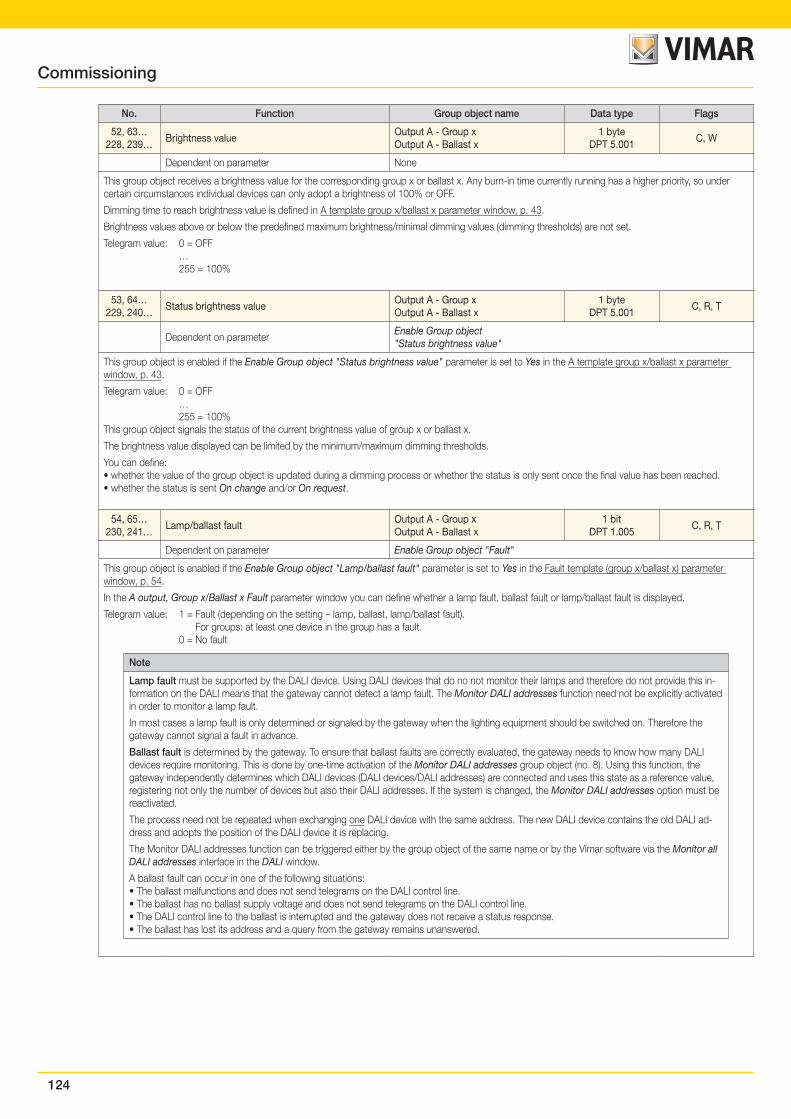
124
No. Function Group object name Data type Flags
52, 63…228, 239…
Brightness valueOutput A - Group xOutput A - Ballast x
1 byteDPT 5.001
C, W
Dependent on parameter None
This group object receives a brightness value for the corresponding group x or ballast x. Any burn-in time currently running has a higher priority, so under certain circumstances individual devices can only adopt a brightness of 100% or OFF.
Dimming time to reach brightness value is defined in A template group x/ballast x parameter window, p. 43.
Brightness values above or below the predefined maximum brightness/minimal dimming values (dimming thresholds) are not set.
Telegram value: 0 = OFF … 255 = 100%
53, 64…229, 240…
Status brightness valueOutput A - Group xOutput A - Ballast x
1 byteDPT 5.001
C, R, T
Dependent on parameterEnable Group object "Status brightness value"
This group object is enabled if the Enable Group object "Status brightness value" parameter is set to Yes in the A template group x/ballast x parameter window, p. 43.
Telegram value: 0 = OFF … 255 = 100%This group object signals the status of the current brightness value of group x or ballast x.
The brightness value displayed can be limited by the minimum/maximum dimming thresholds.
You can define:• whether the value of the group object is updated during a dimming process or whether the status is only sent once the final value has been reached.• whether the status is sent On change and/or On request.
54, 65…230, 241…
Lamp/ballast faultOutput A - Group xOutput A - Ballast x
1 bitDPT 1.005
C, R, T
Dependent on parameter Enable Group object "Fault"
This group object is enabled if the Enable Group object "Lamp/ballast fault" parameter is set to Yes in the Fault template (group x/ballast x) parameter window, p. 54.
In the A output, Group x/Ballast x Fault parameter window you can define whether a lamp fault, ballast fault or lamp/ballast fault is displayed.
Telegram value: 1 = Fault (depending on the setting – lamp, ballast, lamp/ballast fault). For groups: at least one device in the group has a fault. 0 = No fault
Note
Lamp fault must be supported by the DALI device. Using DALI devices that do no not monitor their lamps and therefore do not provide this in-formation on the DALI means that the gateway cannot detect a lamp fault. The Monitor DALI addresses function need not be explicitly activated in order to monitor a lamp fault.
In most cases a lamp fault is only determined or signaled by the gateway when the lighting equipment should be switched on. Therefore the gateway cannot signal a fault in advance.
Ballast fault is determined by the gateway. To ensure that ballast faults are correctly evaluated, the gateway needs to know how many DALI devices require monitoring. This is done by one-time activation of the Monitor DALI addresses group object (no. 8). Using this function, the gateway independently determines which DALI devices (DALI devices/DALI addresses) are connected and uses this state as a reference value, registering not only the number of devices but also their DALI addresses. If the system is changed, the Monitor DALI addresses option must be reactivated.
The process need not be repeated when exchanging one DALI device with the same address. The new DALI device contains the old DALI ad-dress and adopts the position of the DALI device it is replacing.
The Monitor DALI addresses function can be triggered either by the group object of the same name or by the Vimar software via the Monitor all DALI addresses interface in the DALI window.
A ballast fault can occur in one of the following situations:• The ballast malfunctions and does not send telegrams on the DALI control line.• The ballast has no ballast supply voltage and does not send telegrams on the DALI control line.• The DALI control line to the ballast is interrupted and the gateway does not receive a status response.• The ballast has lost its address and a query from the gateway remains unanswered.
Commissioning
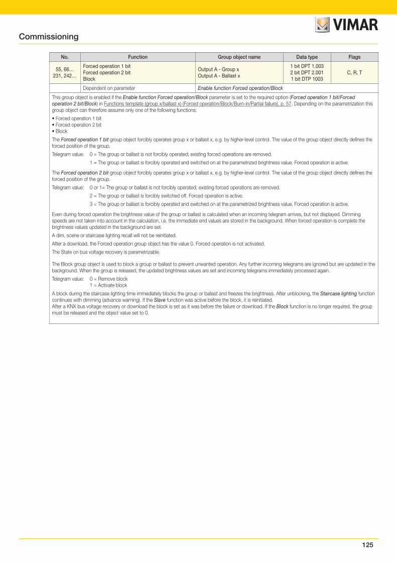
125
No. Function Group object name Data type Flags
55, 66…231, 242…
Forced operation 1 bitForced operation 2 bitBlock
Output A - Group xOutput A - Ballast x
1 bit DPT 1.0032 bit DPT 2.0011 bit DTP 1003
C, R, T
Dependent on parameter Enable function Forced operation/Block
This group object is enabled if the Enable function Forced operation/Block parameter is set to the required option (Forced operation 1 bit/Forced operation 2 bit/Block) in Functions template (group x/ballast x) (Forced operation/Block/Burn-in/Partial failure), p. 57. Depending on the parametrization this group object can therefore assume only one of the following functions:
• Forced operation 1 bit• Forced operation 2 bit• Block
The Forced operation 1 bit group object forcibly operates group x or ballast x, e.g. by higher-level control. The value of the group object directly defines the forced position of the group.
Telegram value: 0 = The group or ballast is not forcibly operated; existing forced operations are removed.
1 = The group or ballast is forcibly operated and switched on at the parametrized brightness value. Forced operation is active.
The Forced operation 2 bit group object forcibly operates group x or ballast x, e.g. by higher-level control. The value of the group object directly defines the forced position of the group.
Telegram value: 0 or 1= The group or ballast is not forcibly operated; existing forced operations are removed.
2 = The group or ballast is forcibly switched off. Forced operation is active.
3 = The group or ballast is forcibly operated and switched on at the parametrized brightness value. Forced operation is active.
Even during forced operation the brightness value of the group or ballast is calculated when an incoming telegram arrives, but not displayed. Dimming speeds are not taken into account in the calculation, i.e. the immediate end values are stored in the background. When forced operation is complete the brightness values updated in the background are set.
A dim, scene or staircase lighting recall will not be reinitiated.
After a download, the Forced operation group object has the value 0. Forced operation is not activated.
The State on bus voltage recovery is parametrizable.
The Block group object is used to block a group or ballast to prevent unwanted operation. Any further incoming telegrams are ignored but are updated in the background. When the group is released, the updated brightness values are set and incoming telegrams immediately processed again.
Telegram value: 0 = Remove block 1 = Activate block
A block during the staircase lighting time immediately blocks the group or ballast and freezes the brightness. After unblocking, the Staircase lighting function continues with dimming (advance warning). If the Slave function was active before the block, it is reinitiated.After a KNX bus voltage recovery or download the block is set as it was before the failure or download. If the Block function is no longer required, the group must be released and the object value set to 0.
Commissioning
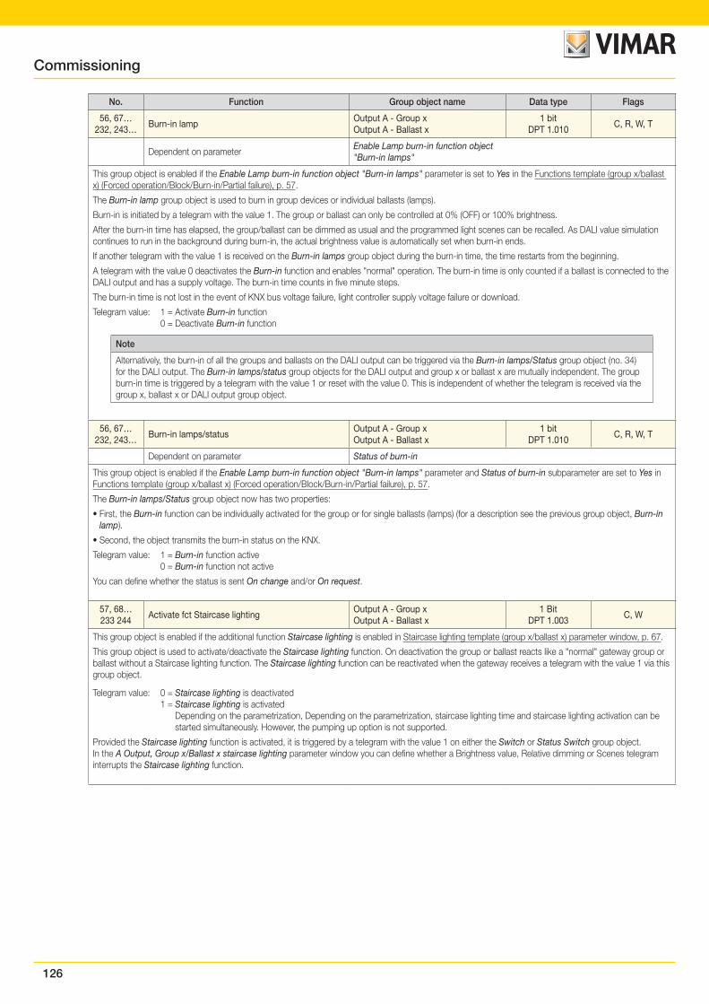
126
No. Function Group object name Data type Flags
56, 67…232, 243…
Burn-in lampOutput A - Group xOutput A - Ballast x
1 bitDPT 1.010
C, R, W, T
Dependent on parameterEnable Lamp burn-in function object "Burn-in lamps"
This group object is enabled if the Enable Lamp burn-in function object "Burn-in lamps" parameter is set to Yes in the Functions template (group x/ballast x) (Forced operation/Block/Burn-in/Partial failure), p. 57.
The Burn-in lamp group object is used to burn in group devices or individual ballasts (lamps).
Burn-in is initiated by a telegram with the value 1. The group or ballast can only be controlled at 0% (OFF) or 100% brightness.
After the burn-in time has elapsed, the group/ballast can be dimmed as usual and the programmed light scenes can be recalled. As DALI value simulation continues to run in the background during burn-in, the actual brightness value is automatically set when burn-in ends.
If another telegram with the value 1 is received on the Burn-in lamps group object during the burn-in time, the time restarts from the beginning.
A telegram with the value 0 deactivates the Burn-in function and enables "normal" operation. The burn-in time is only counted if a ballast is connected to the DALI output and has a supply voltage. The burn-in time counts in five minute steps.
The burn-in time is not lost in the event of KNX bus voltage failure, light controller supply voltage failure or download.
Telegram value: 1 = Activate Burn-in function 0 = Deactivate Burn-in function
Note
Alternatively, the burn-in of all the groups and ballasts on the DALI output can be triggered via the Burn-in lamps/Status group object (no. 34) for the DALI output. The Burn-in lamps/status group objects for the DALI output and group x or ballast x are mutually independent. The group burn-in time is triggered by a telegram with the value 1 or reset with the value 0. This is independent of whether the telegram is received via the group x, ballast x or DALI output group object.
56, 67…232, 243…
Burn-in lamps/statusOutput A - Group xOutput A - Ballast x
1 bitDPT 1.010
C, R, W, T
Dependent on parameter Status of burn-in
This group object is enabled if the Enable Lamp burn-in function object "Burn-in lamps" parameter and Status of burn-in subparameter are set to Yes in Functions template (group x/ballast x) (Forced operation/Block/Burn-in/Partial failure), p. 57.
The Burn-in lamps/Status group object now has two properties:
• First, the Burn-in function can be individually activated for the group or for single ballasts (lamps) (for a description see the previous group object, Burn-in lamp).
• Second, the object transmits the burn-in status on the KNX.
Telegram value: 1 = Burn-in function active 0 = Burn-in function not active
You can define whether the status is sent On change and/or On request.
57, 68…233 244
Activate fct Staircase lightingOutput A - Group xOutput A - Ballast x
1 BitDPT 1.003
C, W
This group object is enabled if the additional function Staircase lighting is enabled in Staircase lighting template (group x/ballast x) parameter window, p. 67.
This group object is used to activate/deactivate the Staircase lighting function. On deactivation the group or ballast reacts like a "normal" gateway group or ballast without a Staircase lighting function. The Staircase lighting function can be reactivated when the gateway receives a telegram with the value 1 via this group object.
Telegram value: 0 = Staircase lighting is deactivated 1 = Staircase lighting is activated Depending on the parametrization, Depending on the parametrization, staircase lighting time and staircase lighting activation can be
started simultaneously. However, the pumping up option is not supported.
Provided the Staircase lighting function is activated, it is triggered by a telegram with the value 1 on either the Switch or Status Switch group object.In the A Output, Group x/Ballast x staircase lighting parameter window you can define whether a Brightness value, Relative dimming or Scenes telegram interrupts the Staircase lighting function.
Commissioning
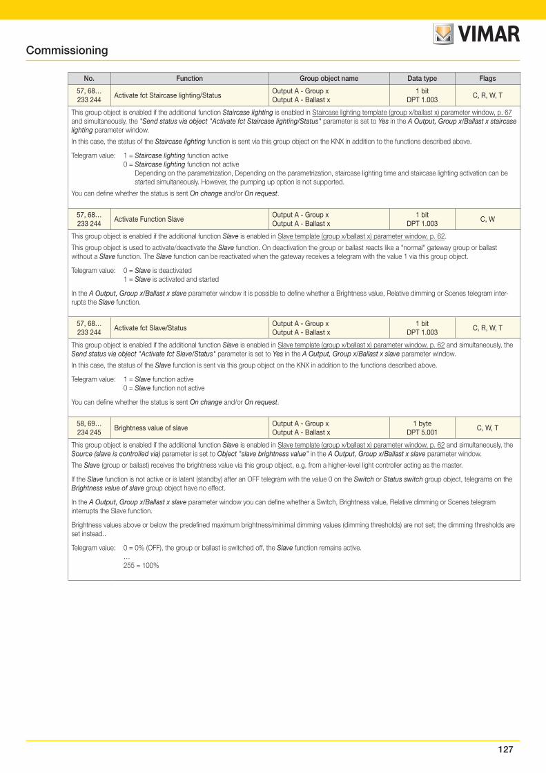
127
No. Function Group object name Data type Flags
57, 68…233 244
Activate fct Staircase lighting/StatusOutput A - Group xOutput A - Ballast x
1 bitDPT 1.003
C, R, W, T
This group object is enabled if the additional function Staircase lighting is enabled in Staircase lighting template (group x/ballast x) parameter window, p. 67 and simultaneously, the "Send status via object "Activate fct Staircase lighting/Status" parameter is set to Yes in the A Output, Group x/Ballast x staircase lighting parameter window.
In this case, the status of the Staircase lighting function is sent via this group object on the KNX in addition to the functions described above.
Telegram value: 1 = Staircase lighting function active 0 = Staircase lighting function not active Depending on the parametrization, Depending on the parametrization, staircase lighting time and staircase lighting activation can be
started simultaneously. However, the pumping up option is not supported.
You can define whether the status is sent On change and/or On request.
57, 68…233 244
Activate Function SlaveOutput A - Group xOutput A - Ballast x
1 bitDPT 1.003
C, W
This group object is enabled if the additional function Slave is enabled in Slave template (group x/ballast x) parameter window, p. 62.
This group object is used to activate/deactivate the Slave function. On deactivation the group or ballast reacts like a "normal" gateway group or ballast without a Slave function. The Slave function can be reactivated when the gateway receives a telegram with the value 1 via this group object.
Telegram value: 0 = Slave is deactivated 1 = Slave is activated and started
In the A Output, Group x/Ballast x slave parameter window it is possible to define whether a Brightness value, Relative dimming or Scenes telegram inter-rupts the Slave function.
57, 68…233 244
Activate fct Slave/StatusOutput A - Group xOutput A - Ballast x
1 bitDPT 1.003
C, R, W, T
This group object is enabled if the additional function Slave is enabled in Slave template (group x/ballast x) parameter window, p. 62 and simultaneously, the Send status via object "Activate fct Slave/Status" parameter is set to Yes in the A Output, Group x/Ballast x slave parameter window.
In this case, the status of the Slave function is sent via this group object on the KNX in addition to the functions described above.
Telegram value: 1 = Slave function active 0 = Slave function not active
You can define whether the status is sent On change and/or On request.
58, 69…234 245
Brightness value of slaveOutput A - Group xOutput A - Ballast x
1 byteDPT 5.001
C, W, T
This group object is enabled if the additional function Slave is enabled in Slave template (group x/ballast x) parameter window, p. 62 and simultaneously, the Source (slave is controlled via) parameter is set to Object "slave brightness value" in the A Output, Group x/Ballast x slave parameter window.
The Slave (group or ballast) receives the brightness value via this group object, e.g. from a higher-level light controller acting as the master.
If the Slave function is not active or is latent (standby) after an OFF telegram with the value 0 on the Switch or Status switch group object, telegrams on the Brightness value of slave group object have no effect.
In the A Output, Group x/Ballast x slave parameter window you can define whether a Switch, Brightness value, Relative dimming or Scenes telegram interrupts the Slave function.
Brightness values above or below the predefined maximum brightness/minimal dimming values (dimming thresholds) are not set; the dimming thresholds are set instead..
Telegram value: 0 = 0% (OFF), the group or ballast is switched off, the Slave function remains active. … 255 = 100%
Commissioning
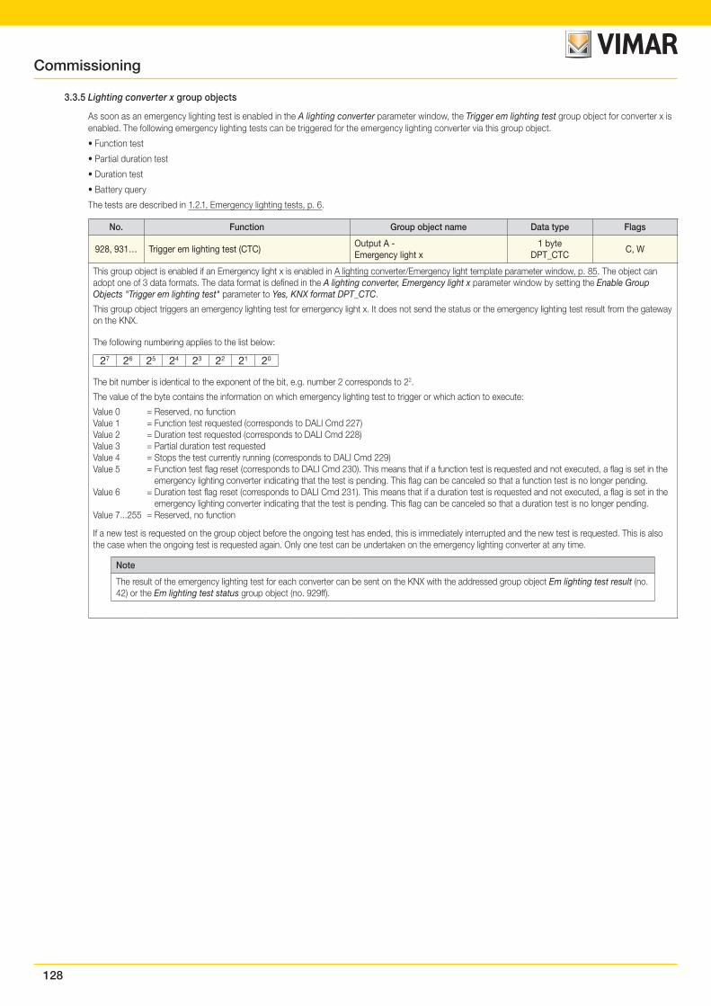
128
3.3.5 Lighting converter x group objects
As soon as an emergency lighting test is enabled in the A lighting converter parameter window, the Trigger em lighting test group object for converter x is enabled. The following emergency lighting tests can be triggered for the emergency lighting converter via this group object.
• Function test
• Partial duration test
• Duration test
• Battery query
The tests are described in 1.2.1, Emergency lighting tests, p. 6.
No. Function Group object name Data type Flags
928, 931… Trigger em lighting test (CTC)Output A - Emergency light x
1 byteDPT_CTC
C, W
This group object is enabled if an Emergency light x is enabled in A lighting converter/Emergency light template parameter window, p. 85. The object can adopt one of 3 data formats. The data format is defined in the A lighting converter, Emergency light x parameter window by setting the Enable Group Objects "Trigger em lighting test" parameter to Yes, KNX format DPT_CTC.
This group object triggers an emergency lighting test for emergency light x. It does not send the status or the emergency lighting test result from the gateway on the KNX.
The following numbering applies to the list below:
27 26 25 24 23 22 21 20
The bit number is identical to the exponent of the bit, e.g. number 2 corresponds to 22.
The value of the byte contains the information on which emergency lighting test to trigger or which action to execute:
Value 0 = Reserved, no functionValue 1 = Function test requested (corresponds to DALI Cmd 227)Value 2 = Duration test requested (corresponds to DALI Cmd 228)Value 3 = Partial duration test requestedValue 4 = Stops the test currently running (corresponds to DALI Cmd 229)Value 5 = Function test flag reset (corresponds to DALI Cmd 230). This means that if a function test is requested and not executed, a flag is set in the
emergency lighting converter indicating that the test is pending. This flag can be canceled so that a function test is no longer pending.Value 6 = Duration test flag reset (corresponds to DALI Cmd 231). This means that if a duration test is requested and not executed, a flag is set in the
emergency lighting converter indicating that the test is pending. This flag can be canceled so that a duration test is no longer pending.Value 7...255 = Reserved, no function
If a new test is requested on the group object before the ongoing test has ended, this is immediately interrupted and the new test is requested. This is also the case when the ongoing test is requested again. Only one test can be undertaken on the emergency lighting converter at any time.
Note
The result of the emergency lighting test for each converter can be sent on the KNX with the addressed group object Em lighting test result (no. 42) or the Em lighting test status group object (no. 929ff).
Commissioning
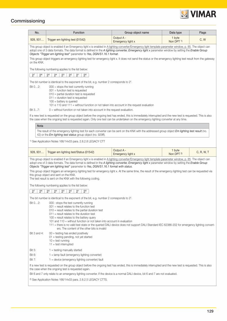
129
No. Function Group object name Data type Flags
928, 931… Trigger em lighting test (01542)Output A - Emergency light x
1 byteNon DPT 1) C, W
This group object is enabled if an Emergency light x is enabled in A lighting converter/Emergency light template parameter window, p. 85. The object can adopt one of 3 data formats. The data format is defined in the A lighting converter, Emergency light x parameter window by setting the Enable Group Objects "Trigger em lighting test" parameter to Yes, DGN/S1.16.1 format.
This group object triggers an emergency lighting test for emergency light x. It does not send the status or the emergency lighting test result from the gateway on the KNX.
The following numbering applies to the list below:
27 26 25 24 23 22 21 20
The bit number is identical to the exponent of the bit, e.g. number 2 corresponds to 22.
Bit 0…2: 000 = stops the test currently running 001 = function test is requested 010 = partial duration test is requested 011 = duration test is requested 100 = battery is queried 101 e 110 and 111 = without function or not taken into account in the request evaluation
Bit 3...7: 0 = without function or not taken into account in the request evaluation.
If a new test is requested on the group object before the ongoing test has ended, this is immediately interrupted and the new test is requested. This is also the case when the ongoing test is requested again. Only one test can be undertaken on the emergency lighting converter at any time.
Nota
The result of the emergency lighting test for each converter can be sent on the KNX with the addressed group object Em lighting test result (no. 42) or the Em lighting test status group object (no. 929ff).
1) See Application Notes 166/14v03 para. 2.8.2.8 LEGACY CTT
928, 931… Trigger em lighting test/Status (01542)Output A - Emergency light x
1 byteNon DPT 2) C, R, W, T
This group object is enabled if an Emergency light x is enabled in A lighting converter/Emergency light template parameter window, p. 85. The object can adopt one of 3 data formats. The data format is defined in the A lighting converter, Emergency light x parameter window by setting the Enable Group Objects "Trigger em lighting test" parameter to Yes, DGN/S1.16.1 format with status.
This group object triggers an emergency lighting test for emergency light x. At the same time, the result of the emergency lighting test can be requested via this group object and sent on the KNX.The test result is sent on the KNX with the following coding.
The following numbering applies to the list below:
27 26 25 24 23 22 21 20
The bit number is identical to the exponent of the bit, e.g. number 2 corresponds to 22.
Bit 0…2: 000 : stops the test currently running 001 = result relates to the function test 010 = result relates to the partial duration test 011 = result relates to the duration test 100 = result relates to the battery query 101 and 110 = without function or not taken into account in evaluation 111 = there is no valid test state or the queried DALI device does not support DALI Standard IEC 62386-202 for emergency lighting convert-
ers. The content of the other bits is invalid
Bit 3 and 4: 00 = testing has ended positively 01 = testing pending, not yet started 10 = test running 11 = test interrupted
Bit 5: 1 = testing manually started
Bit 6: 1 = lamp fault (emergency lighting converter)
Bit 7: 1 = device (emergency lighting converter) fault
If a new test is requested on the group object before the ongoing test has ended, this is immediately interrupted and the new test is requested. This is also the case when the ongoing test is requested again.
Bit 6 and 7 only relate to an emergency lighting converter. If the device is a normal DALI device, bit 6 and 7 are not evaluated.
2) See Application Notes 166/14v03 para. 2.8.2.5 LEGACY CTTS.
Commissioning
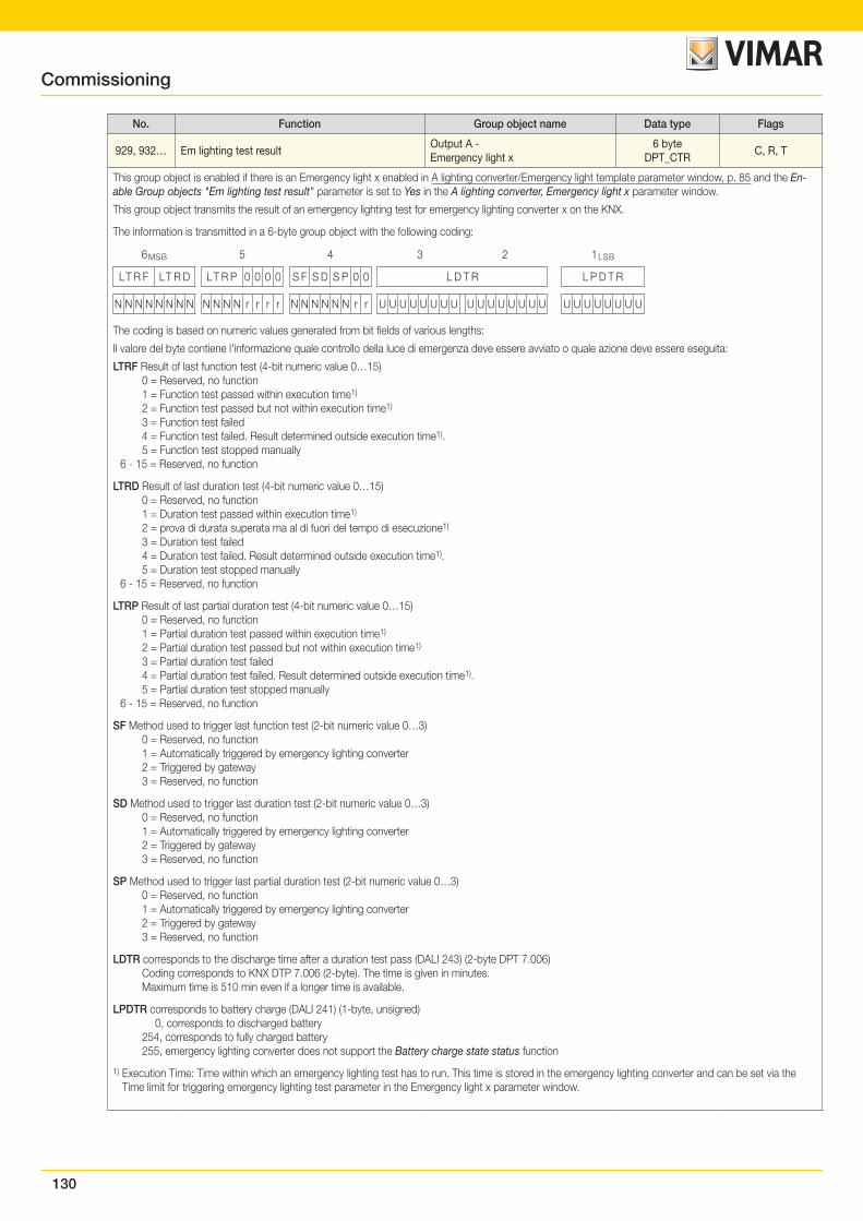
130
No. Function Group object name Data type Flags
929, 932… Em lighting test resultOutput A - Emergency light x
6 byteDPT_CTR
C, R, T
This group object is enabled if there is an Emergency light x enabled in A lighting converter/Emergency light template parameter window, p. 85 and the En-able Group objects "Em lighting test result" parameter is set to Yes in the A lighting converter, Emergency light x parameter window.
This group object transmits the result of an emergency lighting test for emergency lighting converter x on the KNX.
The information is transmitted in a 6-byte group object with the following coding:
6MSB 5 4 3 2 1LSB
LT R F LT R D LT R P 0 0 0 0 S F S D S P 0 0 L D T R L P D T R
N N N N N N N N N N N N r r r r N N N N N N r r U U U U U U U U U U U U U U U U U U U U U U U U
The coding is based on numeric values generated from bit fields of various lengths:
Il valore del byte contiene l'informazione quale controllo della luce di emergenza deve essere avviato o quale azione deve essere eseguita:
LTRF Result of last function test (4-bit numeric value 0…15) 0 = Reserved, no function 1 = Function test passed within execution time1)
2 = Function test passed but not within execution time1)
3 = Function test failed 4 = Function test failed. Result determined outside execution time1). 5 = Function test stopped manually 6 - 15 = Reserved, no function
LTRD Result of last duration test (4-bit numeric value 0…15) 0 = Reserved, no function 1 = Duration test passed within execution time1)
2 = prova di durata superata ma al di fuori del tempo di esecuzione1)
3 = Duration test failed 4 = Duration test failed. Result determined outside execution time1). 5 = Duration test stopped manually 6 - 15 = Reserved, no function
LTRP Result of last partial duration test (4-bit numeric value 0…15) 0 = Reserved, no function 1 = Partial duration test passed within execution time1)
2 = Partial duration test passed but not within execution time1)
3 = Partial duration test failed 4 = Partial duration test failed. Result determined outside execution time1). 5 = Partial duration test stopped manually 6 - 15 = Reserved, no function
SF Method used to trigger last function test (2-bit numeric value 0…3) 0 = Reserved, no function 1 = Automatically triggered by emergency lighting converter 2 = Triggered by gateway 3 = Reserved, no function
SD Method used to trigger last duration test (2-bit numeric value 0…3) 0 = Reserved, no function 1 = Automatically triggered by emergency lighting converter 2 = Triggered by gateway 3 = Reserved, no function
SP Method used to trigger last partial duration test (2-bit numeric value 0…3) 0 = Reserved, no function 1 = Automatically triggered by emergency lighting converter 2 = Triggered by gateway 3 = Reserved, no function
LDTR corresponds to the discharge time after a duration test pass (DALI 243) (2-byte DPT 7.006) Coding corresponds to KNX DTP 7.006 (2-byte). The time is given in minutes. Maximum time is 510 min even if a longer time is available.
LPDTR corresponds to battery charge (DALI 241) (1-byte, unsigned) 0, corresponds to discharged battery 254, corresponds to fully charged battery 255, emergency lighting converter does not support the Battery charge state status function
1) Execution Time: Time within which an emergency lighting test has to run. This time is stored in the emergency lighting converter and can be set via the Time limit for triggering emergency lighting test parameter in the Emergency light x parameter window.
Commissioning
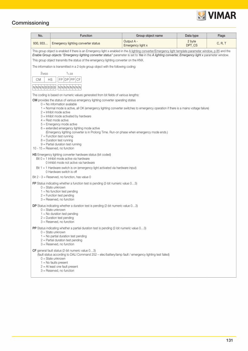
131
No. Function Group object name Data type Flags
930, 933… Emergency lighting converter statusOutput A - Emergency light x
2 byteDPT_CS
C, R, T
This group object is enabled if there is an Emergency light x enabled in the A lighting converter/Emergency light template parameter window, p.85 and the Enable Group objects "Emergency lighting converter status" parameter is set to Yes in the A lighting converter, Emergency light x parameter window.
This group object transmits the status of the emergency lighting converter on the KNX.
The information is transmitted in a 2-byte group object with the following coding:
2MSB 1LSB
CM HS FP DP PP CF
N N N N B B B B N N N N N N N N
The coding is based on numeric values generated from bit fields of various lengths:
CM provides the status of various emergency lighting converter operating states 0 = No information available 1 = Normal mode is active, all OK (emergency lighting converter switches to emergency operation if there is a mains voltage failure) 2 = Inhibit mode active 3 = Inhibit mode activated by hardware 4 = Rest mode active 5 = Emergency mode active 6 = extended emergency lighting mode active (Emergency lighting converter is in Prolong Time. Run-on phase when emergency mode ends.) 7 = Function test running 8 = Duration test running 9 = Partial duration test running 10 - 15 = Reserved, no function
HS Emergency lighting converter hardware status (bit coded) Bit 0 = 1 Inhibit mode active via hardware 0 Inhibit mode not active via hardware
Bit 1 = 1 Hardware switch is on (emergency light activated via hardware input) 0 Hardware switch is off
Bit 2 - 3 = Reserved, no function, has value 0
FP Status indicating whether a function test is pending (2-bit numeric value 0…3) 0 = State unknown 1 = No function test pending 2 = Function test pending 3 = Reserved, no function
DP Status indicating whether a duration test is pending (2-bit numeric value 0…3) 0 = State unknown 1 = No duration test pending 2 = Duration test pending 3 = Reserved, no function
PP Status indicating whether a partial duration test is pending (2-bit numeric value 0…3) 0 = State unknown 1 = No partial duration test pending 2 = Partial duration test pending 3 = Reserved, no function
CF general fault status (2-bit numeric value 0…3) (fault status according to DALI Command 252 – elec/battery/lamp fault / emergency lighting test failed) 0 = State unknown 1 = No faults present 2 = At least one fault present 3 = Reserved, no function
Commissioning

132
4. Planning and applicationIn this section you will find DALI Gateway Basic practical tips and application examples
4.1 DALI addressing
This chapter covers gateway addressing so as to provide a better appreciation of the gateway's functionality.
To control DALI devices individually or in groups, DALI commissioning (configuration) is required. This involves assigning DALI addresses and/or groups to DALI devices.
The gateway executes automatic DALI addressing if the Enable automatic DALI addressing parameter is set to Yes in the A DALI configuration parameter win-dow. The gateway automatically detects the connected DALI equipment and assigns an address in ascending order if the device does not have one.
If automatic DALI addressing is not allowed, there are three alternative options for implementing addressing with the DALI gateway:
• Use the Vimar software
• Press and hold (> 5 seconds) the push button on the DALI gateway
• Trigger DALI addressing group object
In order to implement DALI addressing, the gateway autonomously and automatically checks the DALI devices connected to the DALI output. If it detects equip-ment with a DALI interface that has not been assigned a defined DALI address (default delivery state, DALI short address 255), it automatically assigns one. The detected DALI device will be assigned the first free DALI address (0 to 63) on the output. If no DALI devices have yet been detected, it is assigned the first DALI ad-dress, 0. The second device is assigned DALI address 1, and so on. The sequence in which the DALI master, e.g. the gateway, finds a device with a DALI interface cannot be influenced. If the connected DALI device already has a DALI address, e.g. an exchange device from another system, it will not be changed.
If the new DALI device has a DALI address which is already in use on the output, one of the two DALI devices with the same address will be assigned a new and unused DALI address. This means that the old DALI device which is already connected to the output may receive a new address.
To control groups, the connected DALI devices must be assigned to a group. The Vimar software, which is independent of ETS, is used for this.
4.2 Lamp and ballast monitoring
The gateway can broadcast the fault state of the output's DALI lighting on the KNX bus. A control panel or control center can evaluate and display this information. Required repair measures or corresponding maintenance cycles can be initiated. This makes it possible to integrate the lighting into a higher-level Facility Manage-ment system.
The prerequisite for this is that the lighting equipment is connected to the output of the DALI gateway and features a DALI interface compliant with DIN EN 62386 or DIN EN 60929. There are various options for fault messages:
• For lamp and ballast faults, a fault on the DALI output is transmitted on the KNX. Two separate group objects (Lamp fault and Ballast fault) are available for this purpose. This information indicates that at least one DALI device on the output has a fault.
• Each ballast or group has one group object available for a fault message. This group object can contain information about a lamp or ballast fault, or a logical OR combination of lamp and ballast fault.
• The fault status of an individual DALI device can be requested via- a coded group object (Fault addressed) on the output. This 2-byte group object contains the device or group number (this is parametrizable) and the fault
information (lamp or ballast fault).
• The number of a DALI device or group with a fault can be sent on the KNX as a numeric value via the Ballast number fault group or Group number fault group object. If there are several faults, the number of the next/previous device or group with a fault can be displayed using the Switch up next ballast fault or Switch up next group fault group object. The number (count) of devices or groups with a fault can be sent on the KNX using the Number of ballast faults or Number of group faults group object.
In order to guarantee correct operation the gateway has to know how many ballasts are to be monitored. This is done by one-time activation of the Monitor DALI addresses group object. The gateway uses this function to independently establish how many DALI devices are connected to each output and saves this number as a reference value for the output. If devices are added to or removed from the system, the Monitor DALI addresses function has to be reactivated. This process is only necessary if the number of ballasts per output has changed and not when replacing a ballast. Monitoring can also be implemented in the Vimar software.
Note
In order to detect a lamp fault, the DALI device must make the fault available on the DALI.
This is generally supported by all DALI ballasts. DALI dimmers and DALI switch actuators often do not have this characteristic. To check for this function, refer to the technical data for the DALI device or consult the lamp manufacturer.
Planning and application
133
4.3 Exchange of DALI devices
If a DALI device fails in an existing DALI installation where DALI addresses are assigned without any gaps, a DALI device in the as-delivered state with factory set-tings (without DALI addressing) can be used as a replacement, avoiding the need for re-commissioning. The gateway automatically assigns the new DALI device the first free DALI output address, group assignments and scene parameters of the faulty ballast, and the new device can assume the functions of the failed device as long as it has the same technical characteristics.
Note
The Enable automatic DALI addressing parameter must be enabled in the A DALI configuration parameter window.
If multiple DALI devices on a DALI output fail or there are gaps in the DALI addressing, it is not possible for the gateway to guarantee a unique assignment for the replacement device.
The gateway assigns the new DALI device the first free DALI address on the output. If the new DALI device has a DALI address which is already in use on the output, one of the two DALI devices with the same address will be assigned a new and unused DALI address.
DALI addresses and group assignments can easily be corrected or exchanged without ETS by using the Vimar software drag and drop feature.
If automatic DALI addressing is not enabled, there is no need to enable it via ETS programming. The Vimar software allows you to trigger one-time DALI address-ing.
There is also the option of using the push button (press and hold > 5 seconds) on the gateway to trigger one-time DALI addressing which means that you can exchange a device without using any software at all. The prerequisite for this is that the current DALI addressing has no gaps.
Note
Triggering DALI addressing via the Vimar software or push button does not change any ETS settings. It simply triggers one-time DALI addressing which runs until all the DALI devices have a DALI address and/or there are no duplicate DALI addresses detected. Duplicate addressing is also triggered if applicable. If the one-time DALI addressing process has finished, automatic DALI addressing remains latent if it is parametrized to do so.
4.4 Function circuit diagrams and priorities
The function tables show the effect of various KNX commands when a function is parametrized. The following should be noted here.
Note
Priorities in the gateway from highest to lowest:
1. Forced operation/Block function2. Partial failure function3. Manual operation4. Slave/Staircase lighting/Scene/KNX telegrams function
Note
The Burn-in function sets the minimal dimming value on the ballast to 100%. This sets all brightness values other than 0 to 100%. The same applies for the Forced operation und Scenes functions.
For instance, this means that if a ballast or the group is in burn-in mode, a forced operation is mapped from 50% to 100%.
Note
If the Vimar software is linked to the gateway for commissioning or diagnostics work, the system reacts as follows:
• Provided the Vimar software is in View mode ( ), it has no effect via KNX functions.
• If configuration mode ( ) is activated and the DALI window has been opened, all KNX functions (e.g. forced operation or staircase lighting) are deactivated or set to standby. This is the only way to carry out consistent commissioning. On exiting the Vimar software the functions must be reactivated.
Note
If either the Forced operation/Block or Partial failure function is activated, the gateway only updates incoming KNX commands in the background. The system reacts as follows in this case:
Switch, Brightness value and Scenes commands are invisibly executed in the background, memorizing the end brightness values immediately without transition times. Dimming commands are ignored.
Operating states, e.g. inactive or standby, for the Slave and Staircase lighting functions are also memorized in the background depending on the incoming KNX commands. If the Staircase lighting is active when the higher-level function ends, it is in standby. If slave mode is active, it responds to its master again as soon as the higher-level function ends.
Once the higher-level function ends, the ballast or group adopts the brightness value that would have occurred if the higher-level function had not been executed.
Planning and application
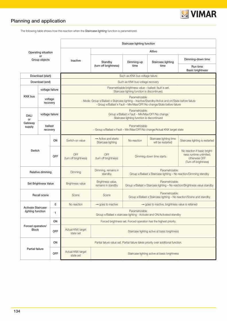
134
The following table shows how the reaction when the Staircase lighting function is parametrized.
Operating situationor
Group objects
Staircase lighting function
Inactive
Attivo
Standby(turn off brightness)
Dimming-up time
Staircase lighting time
Dimming-down time
Run timeBasic brightness
Download (start) Such as KNX bus voltage failure
Download (end) Such as KNX bus voltage recovery
KNX bus
voltage failureParametrizable brightness value – ballast: fault is set.
Staircase lighting function is discontinued.
voltage recovery
Parametrizable:- Mode: Group x/Ballast x Staircase lighting – Inactive/Standby/Active and on/State before failure
- Group x/Ballast x Fault – Min/Max/OFF/No change/State before failure
DALIor
Gatewaysupply
voltage failureParametrizable:
Group x/Ballast x Fault – Min/Max/OFF/No changeStaircase lighting function is discontinued
ballast recovery
Parametrizable:- Group x/Ballast x Fault – Min/Max/OFF/No change/Actual KNX target state
Switch
ON Switch-on value Active and starts
Staircase lightingNo reaction
Staircase lighting time will be restarted
Staircase lighting is restarted
OFFOFF
(turn off brightness)OFF
(turn off brightness)Dimming-down time starts
No reaction if basic bright-ness runtime unlimited,
otherwise OFF (Turn off brightness)
Relative dimming DimmingDimming, remains in
standbyParametrizable:
Group x/Ballast x Staircase lighting – No reaction/Dimming standby
Set Brightness Value Brightness valueBrightness value,
remains in standbyParametrizable:
Group x/Ballast x Staircase lighting – No reaction/Brightness value standby
Recall scene Scene SceneParametrizable:
Group x/Ballast x Staircase lighting – No reaction/Scene and standby
Activate Staircase lighting function
0 No reaction goes to inactive goes to inactive, brightness value is retained
1Parametrizable:
Group x/Ballast x staircase lighting - Activate and ON/Activated standby
Forced operation/Block
ON Forced brightness set. Forced operation has the highest priority.
OFFActual KNX target
state setStaircase lighting active at basic brightness
Partial failure
ON Partial failure value set. Partial failure takes priority over additional function.
OFFActual KNX target
state setStaircase lighting active at basic brightness
Planning and application
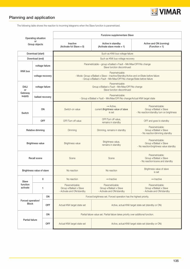
135
Operating situationor
Group objects
Funzione supplementare Slave
Inactive(Activate fct Slave = 0)
Active in standby(Activate slave mode = 1)
Active and ON (running)(Function = 1)
Download (start) Such as KNX bus voltage failure
Download (end) Such as KNX bus voltage recovery
KNX bus
voltage failureParametrizable – group x/ballast x Fault – Min/Max/OFF/No change
Slave function discontinued
voltage recoveryParametrizable:
- Mode: Group x/Ballast x Slave – Inactive/Standby/Active and on/State before failure- Group x/Ballast x Fault – Min/Max/OFF/No change/State before failure
DALIor
Gatewaysupply
voltage failureParametrizable:
Group x/Ballast x Fault – Min/Max/OFF/No changeSlave function discontinued
ballast recoveryParametrizable:
- Group x/Ballast x Fault – Min/Max/OFF/No change/Actual KNX target state
SwitchON Switch-on value
Active, current Brightness value of slave
is set
Parametrizable:Group x/Ballast x Slave
- No reaction/standby turn on brightness
OFF OFF/Turn off valueOFF/Turn off value,remains in standby
OFF and goes to standby
Relative dimming Dimming Dimming, remains in standbyParametrizable:
Group x/Ballast x Slave- No reaction/dimming standby
Brightness value Brightness valueBrightness value,
remains in standby
Parametrizable:Group x/Ballast x Slave
- No reaction/brightness value standby
Recall scene Scene SceneParametrizable:
Group x/Ballast x Slave- No reaction/scene and standby
Brightness value of slave No reaction No reactionBrightness value of slave
is set
Slave functionactivate
0 No reaction Inactive Inactive
1Parametrizable:
Group x/Ballast x Slave- Activate and ON/standby
Parametrizable:Group x/Ballast x Slave
- Activate and ON/standby
Parametrizable:Group x/Ballast x Slave
- Activate and ON/standby
Forced operation/Block
ON Forced brightness set. Forced operation has the highest priority.
OFF Actual KNX target state set Active, actual KNX target state set (standby or ON)
Partial failure
ON Partial failure value set. Partial failure takes priority over additional function.
OFF Actual KNX target state set Active, actual KNX target state set (standby or ON)
The following table shows the reaction to incoming telegrams when the Slave function is parametrized.
Planning and application
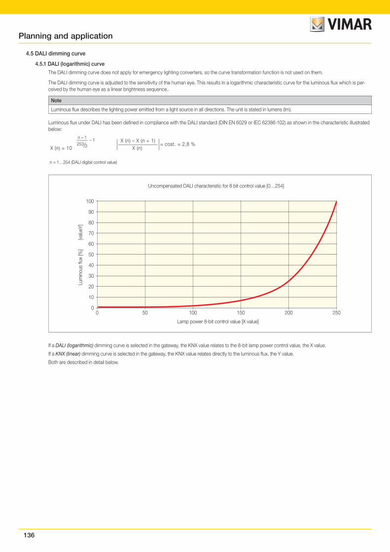
136
4.5 DALI dimming curve
4.5.1 DALI (logarithmic) curve
The DALI dimming curve does not apply for emergency lighting converters, so the curve transformation function is not used on them.
The DALI dimming curve is adjusted to the sensitivity of the human eye. This results in a logarithmic characteristic curve for the luminous flux which is per-ceived by the human eye as a linear brightness sequence..
Note
Luminous flux describes the lighting power emitted from a light source in all directions. The unit is stated in lumens (lm).
Luminous flux under DALI has been defined in compliance with the DALI standard (DIN EN 6029 or IEC 62386-102) as shown in the characteristic illustrated below:
X (n) = 10X (n) – X (n + 1)
X (n)= cost. = 2,8 %
n – 1 – 1253 3
n = 1…254 (DALI digital control value)
00
Lamp power 8-bit control value [X value]
Lum
inou
s flu
x [%
]
[va
lueY
]
Uncompensated DALI characteristic for 8 bit control value [0…254]
50 100 150 200 250
10
20
30
40
50
60
70
80
90
100
If a DALI (logarithmic) dimming curve is selected in the gateway, the KNX value relates to the 8-bit lamp power control value, the X value.
If a KNX (linear) dimming curve is selected in the gateway, the KNX value relates directly to the luminous flux, the Y value.
Both are described in detail below.
Planning and application
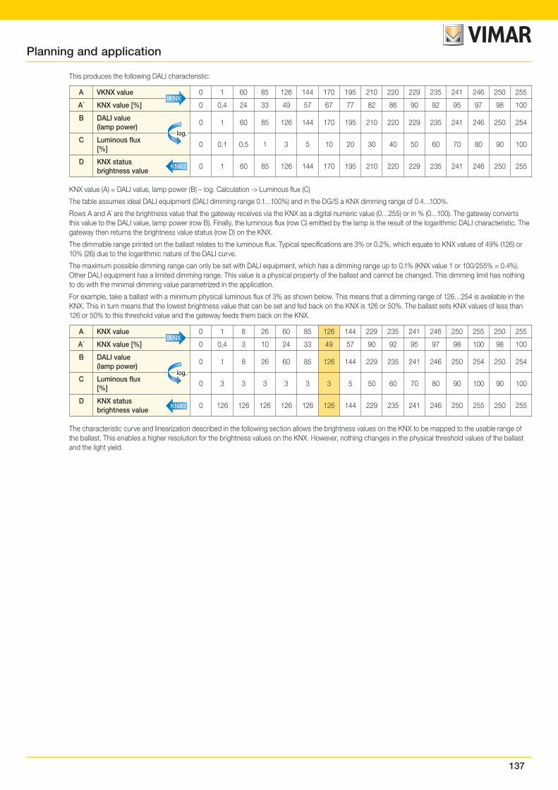
137
This produces the following DALI characteristic:
A VKNX value 0 1 60 85 126 144 170 195 210 220 229 235 241 246 250 255
A´ KNX value [%] 0 0,4 24 33 49 57 67 77 82 86 90 92 95 97 98 100
B DALI value (lamp power)
0 1 60 85 126 144 170 195 210 220 229 235 241 246 250 254
C Luminous flux [%]
0 0.1 0.5 1 3 5 10 20 30 40 50 60 70 80 90 100
D KNX statusbrightness value
0 1 60 85 126 144 170 195 210 220 229 235 241 246 250 255
KNX
log.
KNX
KNX value (A) = DALI value, lamp power (B) – log. Calculation -> Luminous flux (C)
The table assumes ideal DALI equipment (DALI dimming range 0.1…100%) and in the DG/S a KNX dimming range of 0.4…100%.
Rows A and A´ are the brightness value that the gateway receives via the KNX as a digital numeric value (0…255) or in % (0…100). The gateway converts this value to the DALI value, lamp power (row B). Finally, the luminous flux (row C) emitted by the lamp is the result of the logarithmic DALI characteristic. The gateway then returns the brightness value status (row D) on the KNX.
The dimmable range printed on the ballast relates to the luminous flux. Typical specifications are 3% or 0.2%, which equate to KNX values of 49% (126) or 10% (26) due to the logarithmic nature of the DALI curve.
The maximum possible dimming range can only be set with DALI equipment, which has a dimming range up to 0.1% (KNX value 1 or 100/255% = 0.4%). Other DALI equipment has a limited dimming range. This value is a physical property of the ballast and cannot be changed. This dimming limit has nothing to do with the minimal dimming value parametrized in the application.
For example, take a ballast with a minimum physical luminous flux of 3% as shown below. This means that a dimming range of 126…254 is available in the KNX. This in turn means that the lowest brightness value that can be set and fed back on the KNX is 126 or 50%. The ballast sets KNX values of less than 126 or 50% to this threshold value and the gateway feeds them back on the KNX.
A KNX value 0 1 8 26 60 85 126 144 229 235 241 246 250 255 250 255
A´ KNX value [%] 0 0,4 3 10 24 33 49 57 90 92 95 97 98 100 98 100
B DALI value (lamp power)
0 1 8 26 60 85 126 144 229 235 241 246 250 254 250 254
C Luminous flux [%]
0 3 3 3 3 3 3 5 50 60 70 80 90 100 90 100
D KNX status brightness value
0 126 126 126 126 126 126 144 229 235 241 246 250 255 250 255
KNX
log.
KNX
The characteristic curve and linearization described in the following section allows the brightness values on the KNX to be mapped to the usable range of the ballast. This enables a higher resolution for the brightness values on the KNX. However, nothing changes in the physical threshold values of the ballast and the light yield.
Planning and application
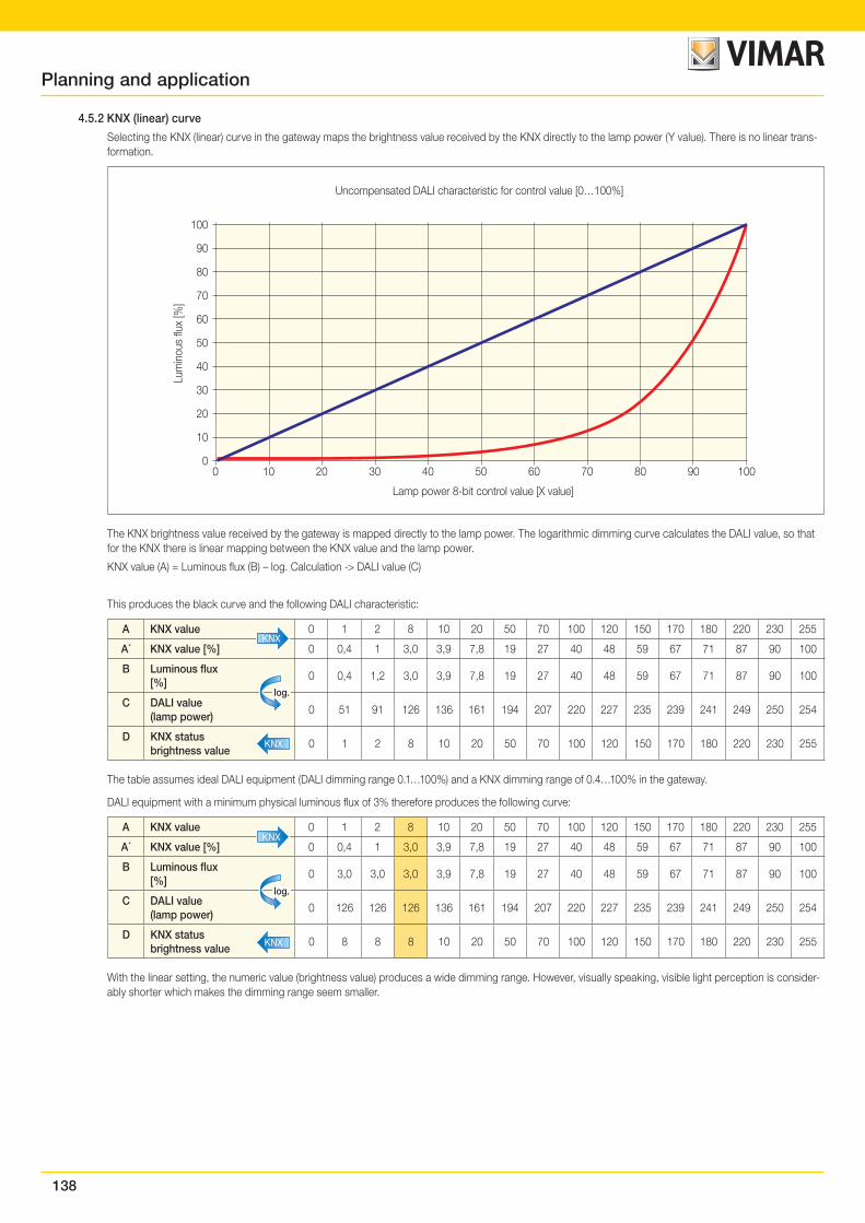
138
4.5.2 KNX (linear) curve
Selecting the KNX (linear) curve in the gateway maps the brightness value received by the KNX directly to the lamp power (Y value). There is no linear trans-formation.
00
Lamp power 8-bit control value [X value]
Lum
inou
s flu
x [%
]Uncompensated DALI characteristic for control value [0…100%]
20 3010 40 50 60 70 80 90 100
10
20
30
40
50
60
70
80
90
100
The KNX brightness value received by the gateway is mapped directly to the lamp power. The logarithmic dimming curve calculates the DALI value, so that for the KNX there is linear mapping between the KNX value and the lamp power.
KNX value (A) = Luminous flux (B) – log. Calculation -> DALI value (C)
This produces the black curve and the following DALI characteristic:
A KNX value 0 1 2 8 10 20 50 70 100 120 150 170 180 220 230 255
A´ KNX value [%] 0 0,4 1 3,0 3,9 7,8 19 27 40 48 59 67 71 87 90 100
B Luminous flux [%]
0 0,4 1,2 3,0 3,9 7,8 19 27 40 48 59 67 71 87 90 100
C DALI value(lamp power)
0 51 91 126 136 161 194 207 220 227 235 239 241 249 250 254
D KNX status brightness value
0 1 2 8 10 20 50 70 100 120 150 170 180 220 230 255
KNX
log.
KNX
The table assumes ideal DALI equipment (DALI dimming range 0.1…100%) and a KNX dimming range of 0.4…100% in the gateway.
DALI equipment with a minimum physical luminous flux of 3% therefore produces the following curve:
A KNX value 0 1 2 8 10 20 50 70 100 120 150 170 180 220 230 255
A´ KNX value [%] 0 0,4 1 3,0 3,9 7,8 19 27 40 48 59 67 71 87 90 100
B Luminous flux [%]
0 3,0 3,0 3,0 3,9 7,8 19 27 40 48 59 67 71 87 90 100
C DALI value(lamp power)
0 126 126 126 136 161 194 207 220 227 235 239 241 249 250 254
D KNX status brightness value
0 8 8 8 10 20 50 70 100 120 150 170 180 220 230 255
KNX
log.
KNX
With the linear setting, the numeric value (brightness value) produces a wide dimming range. However, visually speaking, visible light perception is consider-ably shorter which makes the dimming range seem smaller.
Planning and application
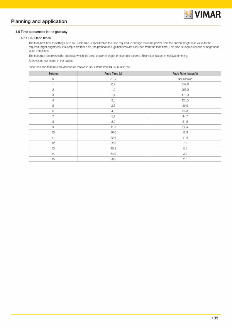
139
4.6 Time sequences in the gateway
4.6.1 DALI fade times
The fade time has 16 settings (0 to 15). Fade time is specified as the time required to change the lamp power from the current brightness value to the required target brightness. If a lamp is switched off, the preheat and ignition time are excluded from the fade time. This time is used in scenes or brightness value transitions.
The fade rate determines the speed at which the lamp power changes in steps per second. This value is used in relative dimming.
Both values are stored in the ballast.
Fade time and fade rate are defined as follows in DALI standard DIN EN 62386-102:
Setting Fade Time (s) Fade Rate (steps/s)
0 < 0,7 Not allowed
1 0,7 357,8
2 1,0 253,0
3 1,4 178,9
4 2,0 126,5
5 2,8 89,5
6 4,0 63,3
7 5,7 44,7
8 8,0 31,6
9 11,3 22,4
10 16,0 15,8
11 22,6 11,2
12 32,0 7,9
13 45,3 5,6
14 64,0 3,9
15 90,5 2,8
Planning and application
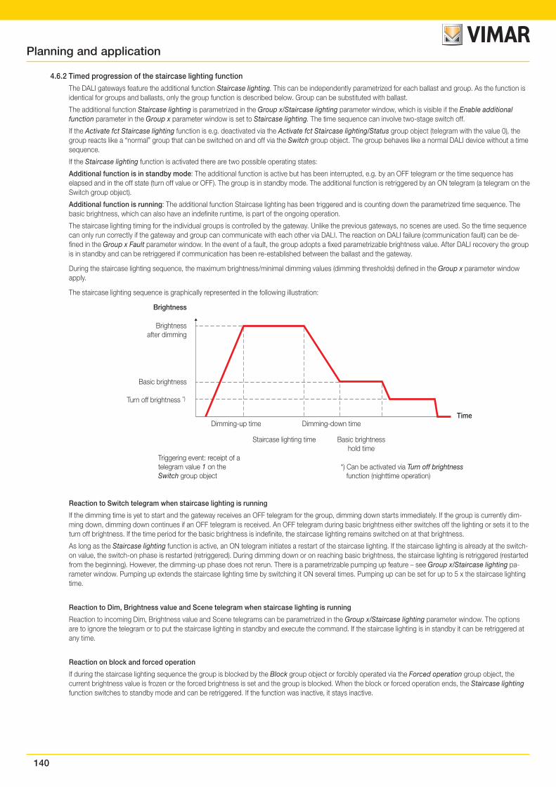
140
4.6.2 Timed progression of the staircase lighting function
The DALI gateways feature the additional function Staircase lighting. This can be independently parametrized for each ballast and group. As the function is identical for groups and ballasts, only the group function is described below. Group can be substituted with ballast.
The additional function Staircase lighting is parametrized in the Group x/Staircase lighting parameter window, which is visible if the Enable additional function parameter in the Group x parameter window is set to Staircase lighting. The time sequence can involve two-stage switch off.
If the Activate fct Staircase lighting function is e.g. deactivated via the Activate fct Staircase lighting/Status group object (telegram with the value 0), the group reacts like a “normal” group that can be switched on and off via the Switch group object. The group behaves like a normal DALI device without a time sequence.
If the Staircase lighting function is activated there are two possible operating states:
Additional function is in standby mode: The additional function is active but has been interrupted, e.g. by an OFF telegram or the time sequence has elapsed and in the off state (turn off value or OFF). The group is in standby mode. The additional function is retriggered by an ON telegram (a telegram on the Switch group object).
Additional function is running: The additional function Staircase lighting has been triggered and is counting down the parametrized time sequence. The basic brightness, which can also have an indefinite runtime, is part of the ongoing operation.
The staircase lighting timing for the individual groups is controlled by the gateway. Unlike the previous gateways, no scenes are used. So the time sequence can only run correctly if the gateway and group can communicate with each other via DALI. The reaction on DALI failure (communication fault) can be de-fined in the Group x Fault parameter window. In the event of a fault, the group adopts a fixed parametrizable brightness value. After DALI recovery the group is in standby and can be retriggered if communication has been re-established between the ballast and the gateway.
During the staircase lighting sequence, the maximum brightness/minimal dimming values (dimming thresholds) defined in the Group x parameter window apply.
The staircase lighting sequence is graphically represented in the following illustration:
Brightness
Time
Brightnessafter dimming
Basic brightness
Turn off brightness *)
Dimming-up time
Staircase lighting time Basic brightnesshold time
Triggering event: receipt of atelegram value 1 on theSwitch group object
Dimming-down time
*) Can be activated via Turn off brightness function (nighttime operation)
Reaction to Switch telegram when staircase lighting is running
If the dimming time is yet to start and the gateway receives an OFF telegram for the group, dimming down starts immediately. If the group is currently dim-ming down, dimming down continues if an OFF telegram is received. An OFF telegram during basic brightness either switches off the lighting or sets it to the turn off brightness. If the time period for the basic brightness is indefinite, the staircase lighting remains switched on at that brightness.
As long as the Staircase lighting function is active, an ON telegram initiates a restart of the staircase lighting. If the staircase lighting is already at the switch-on value, the switch-on phase is restarted (retriggered). During dimming down or on reaching basic brightness, the staircase lighting is retriggered (restarted from the beginning). However, the dimming-up phase does not rerun. There is a parametrizable pumping up feature – see Group x/Staircase lighting pa-rameter window. Pumping up extends the staircase lighting time by switching it ON several times. Pumping up can be set for up to 5 x the staircase lighting time.
Reaction to Dim, Brightness value and Scene telegram when staircase lighting is running
Reaction to incoming Dim, Brightness value and Scene telegrams can be parametrized in the Group x/Staircase lighting parameter window. The options are to ignore the telegram or to put the staircase lighting in standby and execute the command. If the staircase lighting is in standby it can be retriggered at any time.
Reaction on block and forced operation
If during the staircase lighting sequence the group is blocked by the Block group object or forcibly operated via the Forced operation group object, the current brightness value is frozen or the forced brightness is set and the group is blocked. When the block or forced operation ends, the Staircase lighting function switches to standby mode and can be retriggered. If the function was inactive, it stays inactive.
Planning and application
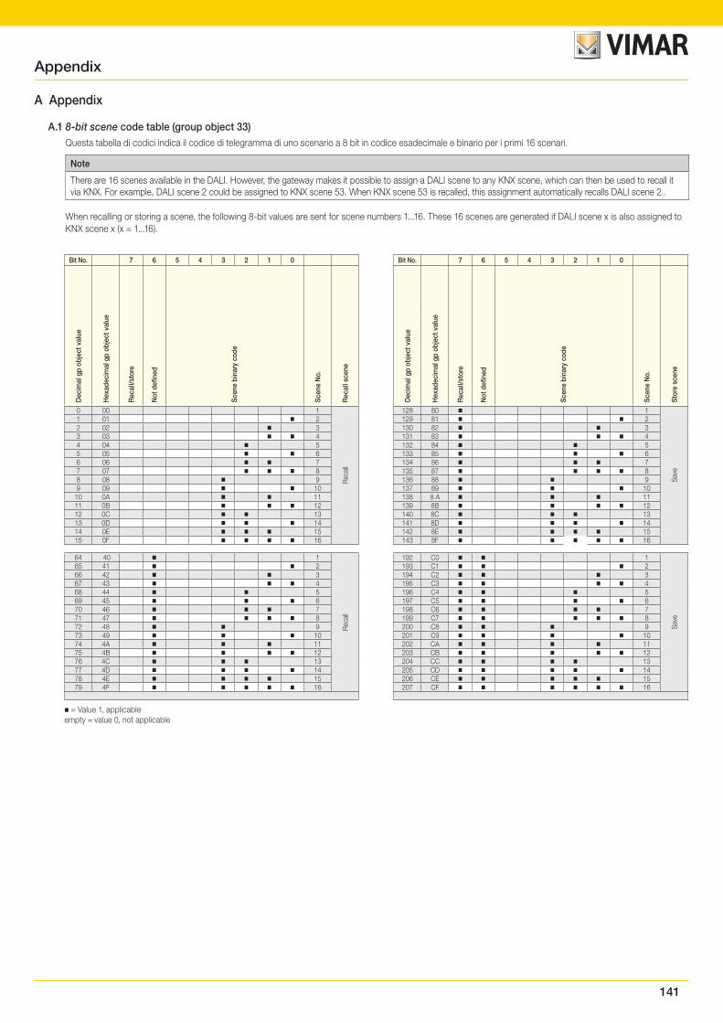
141
Appendix
A Appendix
A.1 8-bit scene code table (group object 33)Questa tabella di codici indica il codice di telegramma di uno scenario a 8 bit in codice esadecimale e binario per i primi 16 scenari.
Note
There are 16 scenes available in the DALI. However, the gateway makes it possible to assign a DALI scene to any KNX scene, which can then be used to recall it via KNX. For example, DALI scene 2 could be assigned to KNX scene 53. When KNX scene 53 is recalled, this assignment automatically recalls DALI scene 2..
When recalling or storing a scene, the following 8-bit values are sent for scene numbers 1...16. These 16 scenes are generated if DALI scene x is also assigned to KNX scene x (x = 1...16).
= Value 1, applicableempty = value 0, not applicable
Bit No. 7 6 5 4 3 2 1 0
Dec
imal
gp
obje
ct v
alue
Hex
adec
imal
gp
obje
ct v
alue
Rec
all/s
tore
Not
defi
ned
Scen
e bi
nary
cod
e
Scen
e N
o.
Rec
all s
cene
0 00 1
Rec
all
1 01 22 02 33 03 44 04 55 05 66 06 77 07 88 08 99 09 1010 0A 1111 0B 1212 0C 1313 0D 1414 0E 1515 0F 16
64 40 1
Rec
all
65 41 266 42 367 43 468 44 569 45 670 46 771 47 872 48 973 49 1074 4A 1175 4B 1276 4C 1377 4D 1478 4E 1579 4F 16
Bit No. 7 6 5 4 3 2 1 0
Dec
imal
gp
obje
ct v
alue
Hex
adec
imal
gp
obje
ct v
alue
Rec
all/s
tore
Not
defi
ned
Scen
e bi
nary
cod
e
Scen
e N
o.
Stor
e sc
ene
128 80 1
Save
129 81 2130 82 3131 83 4132 84 5133 85 6134 86 7135 87 8136 88 9137 89 10138 8 A 11139 8B 12140 8C 13141 8D 14142 8E 15143 8F 16
192 C0 1
Save
193 C1 2194 C2 3195 C3 4196 C4 5197 C5 6198 C6 7199 C7 8200 C8 9201 C9 10202 CA 11203 CB 12204 CC 13205 CD 14206 CE 15207 CF 16
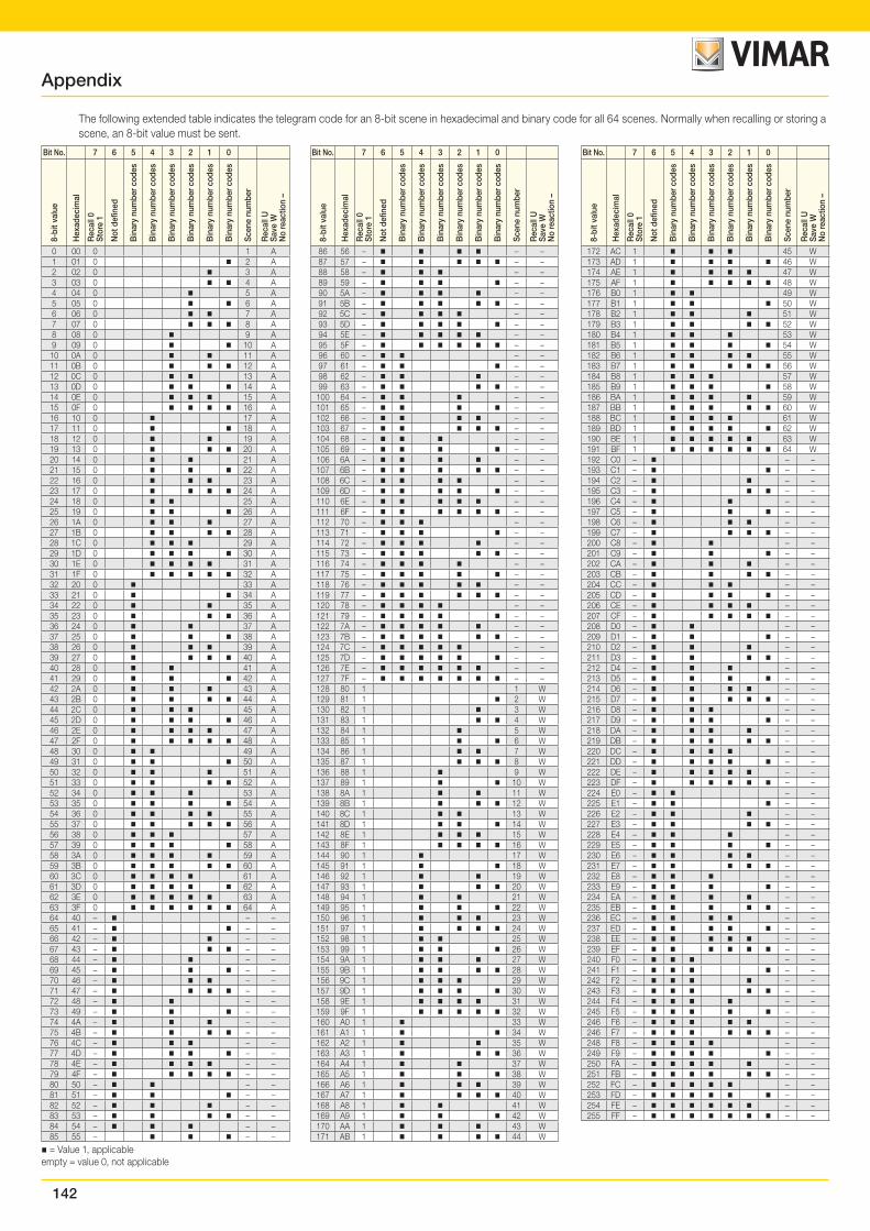
142
= Value 1, applicableempty = value 0, not applicable
The following extended table indicates the telegram code for an 8-bit scene in hexadecimal and binary code for all 64 scenes. Normally when recalling or storing a scene, an 8-bit value must be sent.
Appendix
Bit No. 7 6 5 4 3 2 1 0
8-bi
t val
ue
Hex
adec
imal
Rec
all 0
St
ore
1
Not
defi
ned
Bin
ary
num
ber c
odes
Bin
ary
num
ber c
odes
Bin
ary
num
ber c
odes
Bin
ary
num
ber c
odes
Bin
ary
num
ber c
odes
Bin
ary
num
ber c
odes
Scen
e nu
mbe
r
Rec
all U
Save
WN
o re
actio
n –
0 00 0 1 A1 01 0 2 A2 02 0 3 A3 03 0 4 A4 04 0 5 A5 05 0 6 A6 06 0 7 A7 07 0 8 A8 08 0 9 A9 09 0 10 A
10 0A 0 11 A11 0B 0 12 A12 0C 0 13 A13 0D 0 14 A14 0E 0 15 A15 0F 0 16 A16 10 0 17 A17 11 0 18 A18 12 0 19 A19 13 0 20 A20 14 0 21 A21 15 0 22 A22 16 0 23 A23 17 0 24 A24 18 0 25 A25 19 0 26 A26 1A 0 27 A27 1B 0 28 A28 1C 0 29 A29 1D 0 30 A30 1E 0 31 A31 1F 0 32 A32 20 0 33 A33 21 0 34 A34 22 0 35 A35 23 0 36 A36 24 0 37 A37 25 0 38 A38 26 0 39 A39 27 0 40 A40 28 0 41 A41 29 0 42 A42 2A 0 43 A43 2B 0 44 A44 2C 0 45 A45 2D 0 46 A46 2E 0 47 A47 2F 0 48 A48 30 0 49 A49 31 0 50 A50 32 0 51 A51 33 0 52 A52 34 0 53 A53 35 0 54 A54 36 0 55 A55 37 0 56 A56 38 0 57 A57 39 0 58 A58 3A 0 59 A59 3B 0 60 A60 3C 0 61 A61 3D 0 62 A62 3E 0 63 A63 3F 0 64 A64 40 – – –65 41 – – –66 42 – – –67 43 – – –68 44 – – –69 45 – – –70 46 – – –71 47 – – –72 48 – – –73 49 – – –74 4A – – –75 4B – – –76 4C – – –77 4D – – –78 4E – – –79 4F – – –80 50 – – –81 51 – – –82 52 – – –83 53 – – –84 54 – – –85 55 – – –
Bit No. 7 6 5 4 3 2 1 0
8-bi
t val
ue
Hex
adec
imal
Rec
all 0
St
ore
1
Not
defi
ned
Bin
ary
num
ber c
odes
Bin
ary
num
ber c
odes
Bin
ary
num
ber c
odes
Bin
ary
num
ber c
odes
Bin
ary
num
ber c
odes
Bin
ary
num
ber c
odes
Scen
e nu
mbe
r
Rec
all U
Save
WN
o re
actio
n –
86 56 – – –87 57 – – –88 58 – – –89 59 – – –90 5A – – –91 5B – – –92 5C – – –93 5D – – –94 5E – – –95 5F – – –96 60 – – –97 61 – – –98 62 – – –99 63 – – –
100 64 – – –101 65 – – –102 66 – – –103 67 – – –104 68 – – –105 69 – – –106 6A – – –107 6B – – –108 6C – – –109 6D – – –110 6E – – –111 6F – – –112 70 – – –113 71 – – –114 72 – – –115 73 – – –116 74 – – –117 75 – – –118 76 – – –119 77 – – –120 78 – – –121 79 – – –122 7A – – –123 7B – – –124 7C – – –125 7D – – –126 7E – – –127 7F – – –128 80 1 1 W129 81 1 2 W130 82 1 3 W131 83 1 4 W132 84 1 5 W133 85 1 6 W134 86 1 7 W135 87 1 8 W136 88 1 9 W137 89 1 10 W138 8A 1 11 W139 8B 1 12 W140 8C 1 13 W141 8D 1 14 W142 8E 1 15 W143 8F 1 16 W144 90 1 17 W145 91 1 18 W146 92 1 19 W147 93 1 20 W148 94 1 21 W149 95 1 22 W150 96 1 23 W151 97 1 24 W152 98 1 25 W153 99 1 26 W154 9A 1 27 W155 9B 1 28 W156 9C 1 29 W157 9D 1 30 W158 9E 1 31 W159 9F 1 32 W160 A0 1 33 W161 A1 1 34 W162 A2 1 35 W163 A3 1 36 W164 A4 1 37 W165 A5 1 38 W166 A6 1 39 W167 A7 1 40 W168 A8 1 41 W169 A9 1 42 W170 AA 1 43 W171 AB 1 44 W
Bit No. 7 6 5 4 3 2 1 0
8-bi
t val
ue
Hex
adec
imal
Rec
all 0
St
ore
1
Not
defi
ned
Bin
ary
num
ber c
odes
Bin
ary
num
ber c
odes
Bin
ary
num
ber c
odes
Bin
ary
num
ber c
odes
Bin
ary
num
ber c
odes
Bin
ary
num
ber c
odes
Scen
e nu
mbe
r
Rec
all U
Save
WN
o re
actio
n –
172 AC 1 45 W173 AD 1 46 W174 AE 1 47 W175 AF 1 48 W176 B0 1 49 W177 B1 1 50 W178 B2 1 51 W179 B3 1 52 W180 B4 1 53 W181 B5 1 54 W182 B6 1 55 W183 B7 1 56 W184 B8 1 57 W185 B9 1 58 W186 BA 1 59 W187 BB 1 60 W188 BC 1 61 W189 BD 1 62 W190 BE 1 63 W191 BF 1 64 W192 C0 – – –193 C1 – – –194 C2 – – –195 C3 – – –196 C4 – – –197 C5 – – –198 C6 – – –199 C7 – – –200 C8 – – –201 C9 – – –202 CA – – –203 CB – – –204 CC – – –205 CD – – –206 CE – – –207 CF – – –208 D0 – – –209 D1 – – –210 D2 – – –211 D3 – – –212 D4 – – –213 D5 – – –214 D6 – – –215 D7 – – –216 D8 – – –217 D9 – – –218 DA – – –219 DB – – –220 DC – – –221 DD – – –222 DE – – –223 DF – – –224 E0 – – –225 E1 – – –226 E2 – – –227 E3 – – –228 E4 – – –229 E5 – – –230 E6 – – –231 E7 – – –232 E8 – – –233 E9 – – –234 EA – – –235 EB – – –236 EC – – –237 ED – – –238 EE – – –239 EF – – –240 F0 – – –241 F1 – – –242 F2 – – –243 F3 – – –244 F4 – – –245 F5 – – –246 F6 – – –246 F7 – – –248 F8 – – –249 F9 – – –250 FA – – –251 FB – – –252 FC – – –253 FD – – –254 FE – – –255 FF – – –
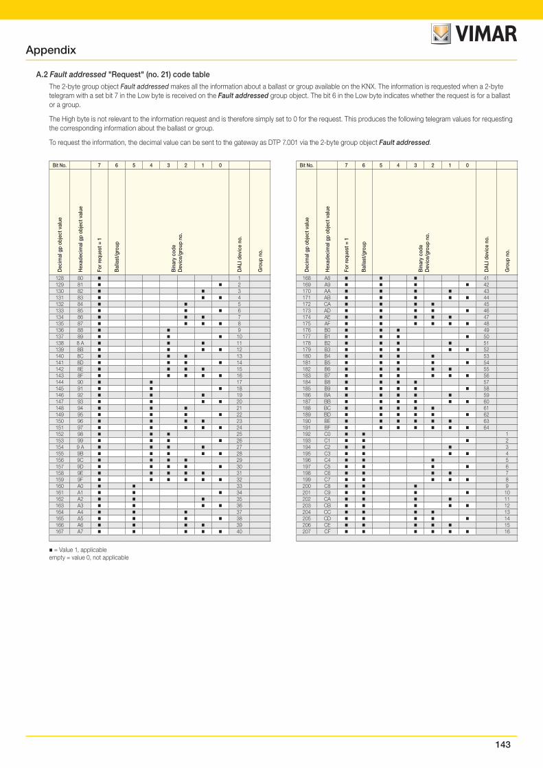
143
Appendix
A.2 Fault addressed "Request" (no. 21) code tableThe 2-byte group object Fault addressed makes all the information about a ballast or group available on the KNX. The information is requested when a 2-byte telegram with a set bit 7 in the Low byte is received on the Fault addressed group object. The bit 6 in the Low byte indicates whether the request is for a ballast or a group.
The High byte is not relevant to the information request and is therefore simply set to 0 for the request. This produces the following telegram values for requesting the corresponding information about the ballast or group.
To request the information, the decimal value can be sent to the gateway as DTP 7.001 via the 2-byte group object Fault addressed.
Bit No. 7 6 5 4 3 2 1 0
Dec
imal
gp
obje
ct v
alue
Hex
adec
imal
gp
obje
ct v
alue
For r
eque
st =
1
Bal
last
/gro
up
Bin
ary
code
Dev
ice/
grou
p no
.
DA
LI d
evic
e no
.
Gro
up n
o.
128 80 1129 81 2130 82 3131 83 4132 84 5133 85 6134 86 7135 87 8136 88 9137 89 10138 8 A 11139 8B 12140 8C 13141 8D 14142 8E 15143 8F 16144 90 17145 91 18146 92 19147 93 20148 94 21149 95 22150 96 23151 97 24152 98 25153 99 26154 9 A 27155 9B 28156 9C 29157 9D 30158 9E 31159 9F 32160 A0 33161 A1 34162 A2 35163 A3 36164 A4 37165 A5 38166 A6 39167 A7 40
Bit No. 7 6 5 4 3 2 1 0
Dec
imal
gp
obje
ct v
alue
Hex
adec
imal
gp
obje
ct v
alue
For r
eque
st =
1
Bal
last
/gro
up
Bin
ary
code
Dev
ice/
grou
p no
.
DA
LI d
evic
e no
.
Gro
up n
o.
168 A8 41169 A9 42170 AA 43171 AB 44172 CA 45173 AD 46174 AE 47175 AF 48176 B0 49177 B1 50178 B2 51179 B3 52180 B4 53181 B5 54182 B6 55183 B7 56184 B8 57185 B9 58186 BA 59187 BB 60188 BC 61189 BD 62190 BE 63191 BF 64192 C0 1193 C1 2194 C2 3195 C3 4196 C4 5197 C5 6198 C6 7199 C7 8200 C8 9201 C9 10202 CA 11203 CB 12204 CC 13205 CD 14206 CE 15207 CF 16
= Value 1, applicableempty = value 0, not applicable
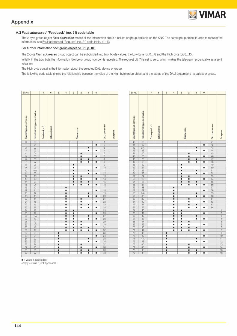
144
A.3 Fault addressed "Feedback" (no. 21) code tableThe 2-byte group object Fault addressed makes all the information about a ballast or group available on the KNX. The same group object is used to request the information, see Fault addressed "Request" (no. 21) code table, p. 143.
For further information see: group object no. 21, p. 109.
The 2-byte Fault addressed group object can be subdivided into two 1-byte values: the Low byte (bit 0…7) and the High byte (bit 8…15).
Initially, in the Low byte the information (device or group number) is repeated. The request bit (7) is set to zero, which makes the telegram recognizable as a sent telegram.
The High byte contains the information about the selected DALI device or group.
The following code table shows the relationship between the value of the High byte group object and the status of the DALI system and its ballast or group.
Bit No. 7 6 5 4 3 2 1 0
Dec
imal
gp
obje
ct v
alue
Hex
adec
imal
gp
obje
ct v
alue
Feed
back
= 0
Bal
last
/gro
up
Bin
ary
code
DA
LI d
evic
e no
.
Gro
up n
o.
0 00 11 01 22 02 33 03 44 04 55 05 66 06 77 07 88 08 99 09 10
10 0 A 1111 0B 1212 0C 1313 0D 1414 0E 1515 0F 1616 10 1717 11 1818 12 1919 13 2020 14 2121 15 2222 16 2323 17 2424 18 2525 19 2626 1 A 2727 1B 2828 1C 2929 1D 3030 1E 3131 1F 3232 20 3333 21 3434 22 3535 23 3636 24 3737 25 3838 26 3939 27 40
Bit No. 7 6 5 4 3 2 1 0
Dec
imal
gp
obje
ct v
alue
Hex
adec
imal
gp
obje
ct v
alue
For r
eque
st =
1
Bal
last
/gro
up
Bin
ary
code
DA
LI d
evic
e no
.
Gro
up n
o.
40 28 4141 29 4242 2 A 4343 2B 4444 2C 4545 2D 4646 2E 4747 2F 4848 30 4949 31 5050 32 5151 33 5252 34 5353 35 5454 36 5555 37 5656 38 5757 39 5858 3 A 5959 3B 6060 3C 6161 3D 6262 3E 6363 3F 6464 40 165 41 266 42 367 43 468 44 569 45 670 46 771 47 872 48 973 49 1074 4 A 1175 4B 1276 4C 1377 4D 1478 4E 1579 4F 16
= Value 1, applicableempty = value 0, not applicable
Appendix
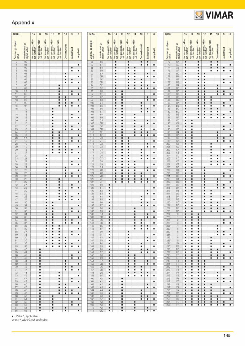
145
Bit No. 15 14 13 12 11 10 9 8
Dec
imal
gp
obje
ct
valu
e
Hex
adec
imal
gp
obje
ct v
alue
Not
ass
igne
d, w
ith-
out f
unct
ion
Not
ass
igne
d, w
ith-
out f
unct
ion
Not
ass
igne
d, w
ith-
out f
unct
ion
Not
ass
igne
d, w
ith-
out f
unct
ion
Not
ass
igne
d, w
ith-
out f
unct
ion
Con
vert
er fa
ult
Bal
last
faul
t
Lam
p fa
ult
0 001 01 2 02 3 03 4 04 5 05 6 06 7 07 8 08 9 09
10 0 A 11 0B 12 0C 13 0D 14 0E 15 0F 16 10 17 11 18 12 19 13 20 14 21 15 22 16 23 17 24 18 25 19 26 1 A 27 1B 28 1C 29 1D 30 1E 31 1F 32 20 33 21 34 22 35 23 36 24 37 25 38 26 39 27 40 28 41 29 42 2 A 43 2B 44 2C 45 2D 46 2E 47 2F 48 30 49 31 50 32 51 33 52 34 53 35 54 36 55 37 56 38 57 39 58 3 A 59 3B 60 3C 61 3D 62 3E 63 3F 64 40 65 41 66 42 67 43 68 44 69 45 70 46 71 47 72 48 73 49 74 4 A 75 4B 76 4C 77 4D 78 4E 79 4F 80 50 81 51 82 52 83 53 84 54 85 55
Bit No. 15 14 13 12 11 10 9 8
Dec
imal
gp
obje
ct
valu
e
Hex
adec
imal
gp
obje
ct v
alue
Not
ass
igne
d, w
ith-
out f
unct
ion
Not
ass
igne
d, w
ith-
out f
unct
ion
Not
ass
igne
d, w
ith-
out f
unct
ion
Not
ass
igne
d, w
ith-
out f
unct
ion
Not
ass
igne
d, w
ith-
out f
unct
ion
Con
vert
er fa
ult
Bal
last
faul
t
Lam
p fa
ult
86 56 87 57 88 58 89 59 90 5 A 91 5B 92 5C 93 5D 94 5E 95 5F 96 60 97 61 98 62 99 63 100 64 101 65 102 66 103 67 104 68 105 69 106 6 A 107 6B 108 6C 109 6D 110 6E 111 6F 112 70 113 71 114 72 115 73 116 74 117 75 118 76 119 77 120 78 121 79 122 7 A 123 7B 124 7C 125 7D 126 7E 127 7F 128 80 129 81 130 82 131 83 132 84 133 85 134 86 135 87 136 88 137 89 138 8 A 139 8B 140 8C 141 8D 142 8E 143 8F 144 90 145 91 146 92 147 93 148 94 149 95 150 96 151 97 152 98 153 99 154 9 A 155 9B 156 9C 157 9D 158 9E 159 9F 160 A0 161 A1 162 A2 163 A3 164 A4 165 A5 166 A6 167 A7 168 A8 169 A9 170 AA 171 GIÙ
Bit No. 15 14 13 12 11 10 9 8
Dec
imal
gp
obje
ct
valu
e
Hex
adec
imal
gp
obje
ct v
alue
Not
ass
igne
d, w
ith-
out f
unct
ion
Not
ass
igne
d, w
ith-
out f
unct
ion
Not
ass
igne
d, w
ith-
out f
unct
ion
Not
ass
igne
d, w
ith-
out f
unct
ion
Not
ass
igne
d, w
ith-
out f
unct
ion
Con
vert
er fa
ult
Bal
last
faul
t
Lam
p fa
ult
172 CA 173 AD 174 AE 175 AF 176 B0 177 B1 178 B2 179 B3 180 B4 181 B5 182 B6 183 B7 184 B8 185 B9 186 BA 187 BB 188 BC 189 BD 190 BE 191 BF 192 C0 193 C1 194 C2 195 C3 196 C4 197 C5 198 C6 199 C7 200 C8 201 C9 202 CA 203 CB 204 CC 205 CD 206 CE 207 CF 208 D0 209 D1 210 D2 211 D3 212 D4 213 D5 214 D6 215 D7 216 D8 217 D9 218 DA 219 DB 220 CC 221 DD 222 DE 223 DF 224 I0 225 I1 226 I2 227 I3 228 I4 229 I5 230 I6 231 I7 232 I8 233 I9 234 IO 235 EB 236 EC 237 ED 238 EE 239 EF 240 F0 241 F1 242 F2 243 F3 244 F4 245 F5 246 F6 247 F7 248 F8 249 F9 250 FA 251 FB 252 FC 253 FD 254 FE 255 FF
= Value 1, applicableempty = value 0, not applicable
Appendix
146


Viale Vicenza 1436063 Marostica VI - Italy
www.vimar.com01542 EN 01 1706


![[2009.04.07] Implementation of KNX-ZigBee Gateway for …web.ics.purdue.edu/~lee992/papers/isce2009.pdf · Implementation of a KNX-ZigBee Gateway for Home Automation ... based on](https://img.pdfslide.net/doc/110x75/5aa1d51c7f8b9a1f6d8c6ee7/20090407-implementation-of-knx-zigbee-gateway-for-webics-lee992papersisce2009pdfimplementation.jpg)