Embed Size (px)
DESCRIPTION
load cell 1
Citation preview

Instruction manualGebrauchsanleitungMode d ’emploi
9499 053 34202
Sartorius Hamburg GmbH, Meiendorfer Str. 205, 22145 Hamburg, GermanyTel. +49.40.67960.303, Fax. +49.40.67960.383
Compression Load Cell PR 6201
500kg...300tType L, D1, C3
LA, D1E, C3E
Ver.: 2005-05-13
Please noteAny information in this document is subject to change without notice and does not represent a commitment on the part of SARTORIUS. This product should be operated only by trained and qualified personnel. In correspondence concerning this product thetype, name and release number as well as all license numbers in relation to the product have to be quoted.
ImportantThis product is partly copyrighted. It may not be modified or copied and may not be used without purchasing or written authorityfrom the copyright owner (SARTORIUS). By using this product, you agree to be bound by the terms stated herein.
Bitte beachtenAlle Angaben in diesem Dokument sind unverbindlich für SARTORIUS und stehen unter Änderungsvorbehalt. Die Bedienung des Produktes darf nur von geschultem, fach- und sachkundigem Personal durchgeführt werden. Bei Schriftwechsel über dieses Produkt bitte Typ, Bezeichnung und Versionsnummer sowie alle mit dem Produkt in Zusammenhang stehenden Lizenznummern angeben.
WichtigDieses Produkt ist in Teilen urheberrechtlich geschützt. Es darf nicht verändert oder kopiert und ohne Erwerb oder schriftlicheEinwilligung des unheberrechtlichen Eigentümers (SARTORIUS) nicht benutzt werden. Durch die Benutzung dieses Produktes werden obige Bestimmungen von Ihnen anerkannt.
Veuillez noter, s.v.p.L'exploitation de ce produit ne doit s'effectuer que par du personnel autorisé. Dans votre correspondance se rapportant au présentproduit, veuillez toujours spécifier le numéro de type, la description et le numéro de version ainsi que tous les numéros de licence en rapport avec ce produit.
ImportantLes droits d'auteur de toutes les parties de ce produit sont réservés. Ce produit ne doit être ni utilisé ni changé ni copié sans achat de la licence ou accord par écrit. L'utilisation du produit implique la reconnaissance des conditions mentionnées ci-avant.

E -1
1. SAFETY INSTRUCTIONSLoad cell PR 6201 with the relevant mounting kits must be used only for the weighing applications or force measurements for which it is intended. The dimensions of all mounting and structural components must be calculated so that sufficient overload capacity is ensured for loads which may occur while taking the relevant standards into account. In particular, upright weighing objects (vessel etc.) must be safeguarded against the weighing installation turning over or being shifted, thus eliminating danger to humans, animals or goods even in the case of a break in a load cell or mounting element. Installation and repair work must be carried out only by qualified personnel.
2. DESIGN CONSIDERATIONS
The supporting structure of the weigher (i.e. the load cell support) and the vessel or
the weigh bridge must be stable enough to withstand the maximum design loads, horizontal (check with spirit level!) and flat., Vessels should preferably be supported by three load cells, platforms and weigh bridges by 4 or 6 load cells (see fig. 1).
* do not constrain this position
Fig. 1 Location of load cells and constrainers
E -2
Parasitic forces, horizontal forces and torques are disturbances which can generate measuring failures and in case of exceeding the specified limits may damage the load cell. An accurate constraining of the object prevents of damages and measuring errors without affecting the required space for movement. Therefore special attention should be paid to the design, arrangement and condition of the constrainers.
Thermal expansion and contractions of the object are to be taken into account which may affect the required space for vertical movement and thus influence the measuring results.
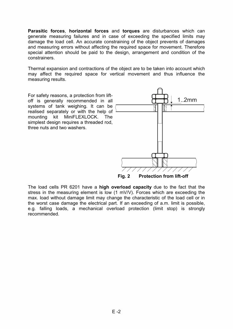
For safety reasons, a protection from lift-off is generally recommended in all systems of tank weighing. It can be realised separately or with the help of mounting kit MiniFLEXLOCK. The simplest design requires a threaded rod, three nuts and two washers.
Fig. 2 Protection from lift-off
The load cells PR 6201 have a high overload capacity due to the fact that the stress in the measuring element is low (1 mV/V). Forces which are exceeding the max. load without damage limit may change the characteristic of the load cell or in the worst case damage the electrical part. If an exceeding of a.m. limit is possible, e.g. falling loads, a mechanical overload protection (limit stop) is strongly recommended.

E -3
3. LOAD CELLType Nominal load Order- code (9405 ... .....) Weight
Emax L LA D1/N D1E/NE C3 C3E net shipping
PR 6201/52 500kg 262 01529 562 01529 262 01521 662 01521 ----- ----- 1,9kg 2,8kg
PR 6201/13 1t 262 01139 562 01139 262 01131 662 01131 ----- ----- 1,9kg 2,8kg
PR 6201/23 2t 262 01239 562 01239 262 01231 662 01231 262 01237 662 01237 1,9kg 2,8kg
PR 6201/33 3t 262 01339 562 01339 262 01331 662 01331 262 01337 662 01337 2,0kg 2,9kg
PR 6201/53 5t 262 01539 562 01539 262 01531 662 01531 262 01537 662 01537 2,0kg 2,9kg
PR 6201/14 10t 262 01149 562 01149 262 01141 662 01141 262 01147 662 01147 2,5kg 3,4kg
PR 6201/24 20t 262 01249 562 01249 262 01241 662 01241 262 01247 662 01247 3,9kg 4,8kg
PR 6201/34 30t ----- 562 01349 262 01341 662 01341 262 01347 662 01347 4,3kg 5,2kg
PR 6201/54 50t 262 01549 562 01549 262 01541 662 01541 262 01547 662 01547 3,9kg 4,8kg
PR 6201/15 100t 262 01159 562 01159 262 01151 662 01151 ----- ----- 11,2kg 12,9kg
PR 6201/25 200t ----- 562 01259 262 01251 662 01251 ----- ----- 26kg 29kg
PR 6201/35 300t ----- ----- 262 01351 662 01351 ----- ----- 26kg 29kg
L D1/N C3
Accuracy class 0,25% 0,04% 0,015%
Emax = 50t...300t 0,5% 0,06% -----
Minimum dead load lowest limit of specified measuring range Emin 0%Emax
Maximum capacity highest limit of specified measuring range Emax see table
Max. usable load upper limit for measurements Eu 200%Emax (.../54: 75t)
Destructive load danger of mechanical destruction Ed >500%Emax (.../54: > 150t)
Minimum LC verification minimum load cell verification interval: v = Emax/Y Y ----- 5000 14000
interval Emax = 1000kg Y ----- 4000 -----
Emax = 500kg Y ----- 2000 -----
Rated output relative output at nominal load Cn 1mV/V
Emax = 50t 2mV/V
Emax = 300t ----- 1.5mV/V -----
Tolerance on rated output permissible deviation from rated output dc <1,0%* <0,25%* <0,07%*
Zero output signal load cell output signal under unloaded conditions S0 <2%* <1%*
Repeatability error max. change in load cell output for repeated loading dRep <0,02%* <0,01%* <0,005%*
Creep during 30 min. max. change in load cell output under nominal load dcr <0,05%* <0,03%* <0,015%*
Non linearity max. deviation from the best straight line through zero dlin <0,25%* <0,03%* <0,01%*
Emax = 50t...300t dlin <0,3%* <0,05%* -----
Hysteresis max. difference in load cel output when loading from
zero to nominal load and unloading to zero
dhy <0,25%* <0,04%* <0,015%*
Emax = 200t...300t dhy <0,25%* <0,06%* -----
Temperature effect Smin max. change of Smin/10K ∆T over BT referred to Cn TKSmin <0,15%/10K* <0,028%/10K* <0,01%/10K*
Emax = 50t...300t TKSmin <0,2%/10K* <0,06%/10K* -----
Temperature effect Cn max. change of Cn/10K ∆T over BT referred to Cn TKc <0,1%/10K* <0,03%/10K* <0,01%/10K*
Input impedance between supply terminals RLC 650Ω+50Ω 650Ω±6Ω
Output impedance between measuring terminals RO 610Ω±3Ω 610Ω±1Ω 610Ω±0,5Ω
Insulation impedance between circuit and housing, 100V DC RIS >5000MΩ
Test voltage (Ex- version ../..E) ----- 500V AC
Recom. supply voltage to hold the specified performance Bu 4...24V
max. supply voltage permissible for continuous operation without damage Umax 32V
Ex- version ../..E Umax ----- 25V
Nominal amb. temp. range to hold the specified performance BT -10...+55°C -10...+40°C
Usable amb. Temp. range permissible for continuous operation without damage BTu -30...+70°C
Ex- version ../..E BTu ----- -30°C...+55°C
Storage temp. range Transportation and storage BTl -40...+70°C
Permissible eccentricity permissible displacement from nominal load line Sex 10mm
Vibration resistance resistance against oscillation (IEC 68-2-6 Fc) - 20g, 100h, 10Hz...Hz
Air pressure effects Influence of ambient air pressure on Smin PKSmin ≤0,05** ≤0,0005** ≤0,0125**
Nominal deflection elastic deformation under nominal load Emax ≤ 30t snom <0,3mm
Emax = 50t snom <0,7mm
Emax = 100t snom <1mm
Emax = 200t snom <1,6mm
Definitions acc. to VDI/VDE 2637 *) related to rated output Cn
**) %Cn/kPa
Emax = 300t snom <2,4mm

E -4
Restoring force in relation to the displacement from the vertical line
Emax ≤ 30t: 0,5%/mm of the actual load on the load cell
Emax ≥50t: 2,5%/mm of the actual load on the load cell
Housing deep drawn, stainless steel 1.4301 hermetically sealed welded, filled with Inert gas
Degree of protection IP 68 (water of 1.5m in depth, 10000h)
Cable Emax ≤ 10t Emax > 10t
diameter 6mm 6mm
length 5m, 12m
cross section 4 x 0,35mm2 4 x 0,35mm
2 (6mm)
bending radius ≥ 50mm (fixed installation)
≥ 150mm (repeated bending) sheath colour grey (standard industrial)
blue (Ex- version) material thermopl. elastomer
colour code red supply +
blue supply -
grey output -
green output +
Certificate of conformity (for PR 6201/...E) protection type intrinsic safety marking EEx ib IIC T6 registration number PTB Nr. Ex-92.C.2137
Load cell with amplifier (PR 6201/..LA; LO > xxx 000 200)output 4...20mA, 2...10mA respectivly
Connection diagram of the load cell
standard load cell with integrated amplifier
The technical data given here, serve only as a product description and are not to be interpreted as guaranteed characteristics in the legal sense.

E-5
PR 6201/52.../23 a=24 R=15 B=150
PR 6201/33.../14 a=34 R=15 B=150
PR 6201/24 a=56 R=35 B=220
PR 6201/34 a=56 R=35 B=220
PR 6201/54 a=56 R=35 B=300

E -6
Fig. 3c Dimensions of PR 6201/25, PR 6201/35 (nominal load 200t, 300t)
4. MOUNTING KITS
PR 6145/00 Mounting plate kit for load cells from PR 6201/52 up to PR 6201/54
PR 6145/08 Mounting plate kit for load cell PR 6201/15
PR 6145/10 Mounting plate kit for load cell PR 6201/25, PR 6201/35
PR 6143/00 MiniFLEXLOCK for load cells from PR 6201/52 up to PR 6201/24
PR 6143/10 MiniFLEXLOCK for load cells from PR 6201/52 up to PR 6201/54
PR 6143/80 Constrainer for 2kN horizontal force
PR 6143/83 Constrainer for 20kN horizontal force
PR 6152/02 Horizontal constrainer for 200kN horizontal force

E -7
4.1 Mounting plate kit PR 6145 (Fig. 4)
All supporting and connecting plates (for foundation and vessel) must be horizontal, flat and rigid. If soft layers are inserted between mounting kit and the stiff adaptation, additional load equalisation plates between mounting kit and soft layer must be provided externally.
PR 6145/00N PR 6145/00S PR 6145/08 PR 6145/10
Nominal load 0,5...50t 0,5...50t L* 100t 200t
Material steel, yellow chromatized
stainless steel steel, yellow chromatized
If a PR 6201/24 or PR 6201/34 or PR 6201/54 are installed with this mounting plate kit, the bottom disc PR 6201/54S must be ordered additionally.
Fig. 4 Mounting plate kit PR 6145
Dimensions of the mounting kit (in mm)
a b c d e f g h i
PR 6145/00 15 190,5 15 150 115 14 65 100 18
PR 6145/08 30 290 30 180 145 18 95 130 18
PR 6145/10 40 385 40 220 185 24 135 180 14
*
*
steel, yellowchromatized

E -8
4.2 MiniFLEXLOCK PR 6143 (Fig. 5)
All supporting and connecting plates (for foundation and vessel) must be horizontal, flat and rigid. If soft layers are inserted between mounting kit and the stiff adaptation, additional load equalisation plates between mounting kit and soft layer must be provided externally.
PR 6143/00N PR 6143/00S PR 6143/10N PR 6143/10S
Nominal load 0,5...20t 0,5...20t L* 0,5...50t 0,5...50t
Horizontal force 25kN 25kN 50kN 50kN
Material steel, yellow chromatized
stainless steel steel, yellow chromatized
stainless steel
If a PR 6201/24 or PR 6201/34 or PR 6201/54 are installed with this mounting plate kit, the bottom disc PR 6201/54S must be ordered additionally.
Fig. 5a MiniFLEXLOCK PR 6143/00
* *
*

E -9
Fig. 5b MiniFLEXLOCK PR 6143/10
For safety reasons, a protection against lift-off is generally recommended. The mounting kits MiniFLEXLOCK are equipped with a threaded hole M16 or M20 respectively so that a protection against lift-off can easily be realised.
Threaded rod property class
acc. to ISO 898
permissible load
PR 6143/00 M16 5.8 20kN
PR 6143/10 M20 5.8 50kN

E -10
4.3 Constrainer PR 6143/8. (Fig. 6) permissible side force Constrainer PR 6143/80 2kN Constrainer PR 6143/83 20kN
Constrainers should not affect the vertical force (load), i.e. the positioning has to be horizontal as accurate as possible and has to ensure the required small horizontal place for vertical movement.
Fig. 6 Constrainer PR 6143/8.

E -11
4.4 Horizontal constrainer PR 6152/02 (Fig. 7)Another method for constraining especially for bigger nominal loads is the use of the rocking pin PR 6152/02 (nominal force up to 200kN) (Fig. 7). Especially for weighbridges the use of consoles with two rocking pins PR 6152/02, bidirectional positioned, is recommended (fig. 7b).
Fig. 7a Horizontal constrainer PR 6152/02
Fig. 7b Mounting a pair of horizontal constrainers PR 6152/02
5. PIVOT
Type nom. load
Emax
Order code
(steel zinc plated)
Order code
(stainless steel)
Weight
(net)
Weight
(shipping)
PR 6101/53 5t 9405 561 01531 9405 561 01532 6,0kg 6,4kg
PR 6101/24 20t 9405 561 01241 9405 561 01242 8,0kg 8,4kg
PR 6101/54 50t 9405 561 01541 9405 561 01542 15,8kg 19,3kg
PR 6101/15 100t 9405 561 01151 ----- 44,75kg 48,25kg
PR 6101/25 200t 9405 561 01251 ----- 115kg 122kg
nominal load upper limit of the specified limit Emax see table abve
max. usable load upper limit for loading Eu 200% Emax
destructive load danger of mechanical damage Ed 300% Emax
max. side force max. permissible horizontal force ----- 10% Emax
material PR 6101/..N steel, zinc plated, yellow chromatized
PR 6101/..S stainless steel 1.4301

E -12
Fig. 8a Pivot PR 6101
Type Dimensions in mm a b c d e f g h
PR 6101/53 15 190,5 ----- 115 150 65 100 14 (4x)
PR 6101/24 15 190,5 ----- 115 150 65 100 14 (4x)
PR 6101/54 15 190,5 115 199 250 65 100 14 (8x)
PR 6101/15 30 290 49 145 300 95 130 18 (8x)
PR 6101/25 40 385 185 375 450 135 180 24 (8x)
Fig. 8b Location of load cells and pivots

E -13
6. Installation
- All electrical welding at the weighing facility must be finished before mounting the load cells!
- Directly when installing the load cell, by- pass the load cell with the flexible copper strap of at least 16mm
2 provided for this purpose (fig. 9), to prevent welding or
lightning stroke current from passing through the load cell and damaging it.
Fig. 9 Flexible copper strap (supplied with every load cell)
In case electrical welding is required in the vicinity of the load cell, disconnect the load cell cable from the measuring instrument, by-pass the load cell carefully with the above-mentioned flexible copper strap. Take care that the grounding clamp of the welding set is fitted as closely as possible to the welding joint in order to prevent a current flow through the load cell.
- Do not lift the load cell on its cable. - Avoid shock stress (falling down, hard shocks)
The load cell must be installed so that its axes is vertical.
The load direction must be as close as possible to measuring axe of the load cell.
Before mounting, fill grease from the bag delivered with the kit into the free space between spherical base of load cell and bottom plate (fig. 3, pos. X) and grease also the load cell head.
Installation of the load disc for the nominal loads between 500kg and 50t
smaller hole (R = 20mm) bigger hole (R = 50mm)
PR 6201/..L, .../..LA 500kg...10t 20t...50t
PR 6201/..D1 500kg...10t 20t...50t
PR 6201/..C3 2t...10t 20t, 30t, 50t
Changes of temperature ≥15 K/h may influence the measuring accuracy. To prevent the load cells from direct heating or cooling effects (sun, wind, heat radiation) heat protection shields or heat protection housings are to be installed if necessary.
To prevent force shunts, all connections of the weighing facility to the surrounding construction (pipes, cables, bellows) must be coupled as flexibly as possible.

E -14
7. Connection
- Protect the cable ends against contamination. - No moisture must penetrate into the open cable end. - Do not shorten the load cell cable. Connect the prepared cable end and roll up the
remaining cable. - The cable screening should not be in contact with earth, except at the connecting
terminal in the measuring instrument. - The load cell cabling should be kept away from power circuits. The distance between the measuring cables and the power supply cables should be
at least 1m. The load cell cables should be laid in separate cable conduits or steel pipes. - Power supply cables should be crossed at right angles.
Fig. 10 Cable junction box
Extension cableFor connection from the cable junction box to the weighing electronics, we recommend using standard extension cable PR 6135. (PR 6136 for EExi applications)
With 4-core extension cables, the load cell supply and output voltage must be connected to pairs of diagonally opposed cores of the extension cable. Resistance per
supply core < 1.25Ω.
capacity insulation impedance
core - core ≤ 100pF/m ≥ 600MΩ x km
core - screen ≤ 150pF/m ≥ 600MΩ x km

E -15
7.1 Connection of load cell with amplifier
Fig. 11a Connection of one load
Fig. 11b Connection of two load cells with amplifier
The grey wire determines the operation mode: - GREY = 0V two load cell mode - GREY = +SUPPLY single load cell mode
The maximum distance between load cell and electronic instrument is 500m.

E-16

E -17
9.2 Checks with multimeter (not for load cell with integrated amplifier)
9.2.1 Check zero output signal of load cell (not possible for version with amplifier) unload load cell disconnect the load cell outputs
Zero output signal
L- version 0,00mV±0,02mV/V D1- version (N- version) 0,00mV±0,01mV/V C3- version (C1,5- version) 0,00mV±0,01mV/V
9.2.2 Check insulation impedance of load cell (not possible for version with amplifier)
never apply the test voltage between the cores of the load cell cable(s) (danger of destroying the load cell)
insulate the load cell cores
maximum test voltage standard industrial 100 V DC intrinsically safe version
(PR 6201/....E) 500 V AC
insulation impedance core - housing >5000MΩ
core - screen >5000MΩ
screen - housing >5000MΩ
9.2.3 Check insulation impedance of extension cable disconnect extension cable and load cells insulate the cores of the extension cable
insulation impedance core - core >600MΩ x km core - screen >600MΩ x km
9.2.4 Check the strain gauge bridge
(not possible for version with amplifier)maximum test voltage standard industrial 32V
intrinsically safe version (PR 6201/....E)
25V
input impedance (red core, blue core)
output impedance (green core, grey core)
L- version 650Ω+50Ω 610Ω±3Ω
D1- version (N- version) 650Ω±6Ω 610Ω±1Ω
C3- version (C1,5- version) 650Ω±6Ω 610Ω±0,5Ω
If all load cells show the same characteristics, check the measuring instrument (weight indicator).

E -18
Caution The load cells PR 6201 are designed as robust as possible for the required
measuring accuracy and have a high reliability. In case of an electrical or mechanical defect, the load cell must be replaced. A load cell repair is impossible.
10. Maintenance- Load cell PR 6201 needs no maintenance. - Pollution on the load cells and on the moveable parts of the weighing installation
have to be cleaned in due time - if the pollution influences the weighing or - if the pollution is aggressive against the different materials of the installation.
The installation parts of the load cell are to be protected by anti-corrosion grease or spray the load cell and is surrounding with off shore all weather protection spray in aggressive pollution.

E -19
11. Spare parts and accessories
Pos. Description Fig. Order code
1 Bottom plate with rubber ring 3a - 1 0,5t...10t 5322 693 91416
2 Bottom plate with rubber ring 3a - 1 20t...50t 5322 693 91165
3 Bottom plate with rubber ring, stainless steel, PR 6143/24S 3a - 1 0,5t...10t 9405 361 43242
4 Bottom plate with rubber ring, stainless steel, PR 6143/54S 3a - 1 20t...50t 9405 361 43542
5 Rubber ring, standard 3a - 2 0,5t...50t 5322 532 70298
6 Rubber ring, food resistance 3a - 2 0,5t...50t 5322 532 70317
7 Load disc, standard, PR 6143/50N 0,5t...50t 9405 361 43501
8 Load disc, stainless steel, PR 6143/50S 0,5t...50t 9405 361 43502
9 Bottom plate 3b 100t 5322 466 81611
10 Housing for bottom plate 3b - 2 100t 5322 466 81609
11 Rubber ring 3b - 3 100t 5322 532 30408
12 Load disc 100t 5322 520 10552
13 Bottom plate 3c 200t, 300t 5322 466 81613
14 Housing for bottom plate 3c - 2 200t, 300t 5322 466 81612
15 Rubber ring 3c - 3 200t, 300t 5322 532 30409
16 Load disc 200t, 300t 5322 520 10553
17 flexible copper strap 16mm2, 400mm long 9 5322 310 30581
18 Mounting kit PR 6145/00N 4 0,5t...50t 9405 361 45001
19 Mounting kit PR 6145/00S 4 0,5t...20t(50t) 9405 361 45002
20 Mounting kit PR 6145/08 4 100t 9405 361 45081
21 Mounting kit PR 6145/10N 4 200t, 300t 9405 361 45101
Horizontal force
22 MiniFLEXLOCK PR 6143/00N, steel, chromatiert 5a ≤20kN 9405 361 43001
23 MiniFLEXLOCK PR 6143/00S, stainless steel 5a ≤17kN 9405 361 43002
25 MiniFLEXLOCK PR 6143/10N, steel, chromatiert 5b ≤50kN 9405 361 43101
26 MiniFLEXLOCK PR 6143/10S, stainless steel 5b ≤45kN 9405 361 43102
27 Constrainer PR 6143/80 6 ≤2kN 9405 361 43801
28 Constrainer PR 6143/83 6 ≤20kN 9405 361 43831
29 Horizontal constrainer PR 6152/02 7 ≤200kN 9405 361 52021
30 Extension cable PR 6135/.. 10 9405 361 35. . 2
31 Extension cable PR 6136/.. for EExi- application 10 9405 361 36. . 1
32 Cable junction box PR 6130/08 10 9405 361 30081
33 Cable junction box PR 6130/60S, stainless steel 10 9405 361 30602
*N steel, zinc plated, yellow chromatized *S stainless steel

! " ! # #
$ % & ! " ! # ' #
( ( ( )
*
+ , ) -
.