Embed Size (px)
Citation preview
Marks awarded to the programmes of the Water Supply and Heating Division:
Coestherm®
Updated certifications are available for downloading in the Website www.coes.it
Ukraine Russia Poland Sweden France Portugal
Italy Germany Germany Austria Spain Australia Croatia
Coesklima Superk®
Italy Germany Russia Ukraine Spain France
REFERENCE STANDARDS
DIN 8077 P.P. pipes - DimensionsDIN 8078 P.P. pipes - Quality regulations - TestsDIN 16962 Connections and fittings for P.P. pipes under vacuum - DimensionsUNI EN ISO 15874 Plastic pipe systems (PP polypropylene) for installations with hot and cold waterDVS 2207 Welding thermoplastic materials using a heating elementDVS 2208 Machinery and devices for welding thermoplastic materialsDIN 2999 Threading for pipes and fittings. Cylindrical internal and conical external threading - DimensionsISO 228 Threading of pipes for coupling on the thread without seal – Design, Dimensions and TolerancesUNI 9182 Cold and hot water supply and distribution systems – Design, testing and management criteria
REFERENCE STANDARDS
UNI 10954-1 Metal-plastic multilayer piping systems for hot and cold water
– LNEC
02_ing_adduzione_e_riscald 9-02-2006 13:17 Pagina 144

145
ylppuS retaW
gni ta eH dna
Wat
er S
upp
lyan
d H
eatin
g /
HVA
C
145
Coesklima Superk® Pag. 146
Coestherm® Pag. 176
HVA
C
Climatika® Pag. 208
02_ing_adduzione_e_riscald 9-02-2006 13:17 Pagina 145
Characteristics and system properties Pag. 179
Fields of use Pag. 180
Connection methods Pag. 181
Assembly and installation instructions Pag. 186
Transport and storage Pag. 194
The programme Pag. 195
02_ing_adduzione_e_riscald 9-02-2006 13:23 Pagina 176

177Coestherm®
02_ing_adduzione_e_riscald 9-02-2006 13:23 Pagina 177
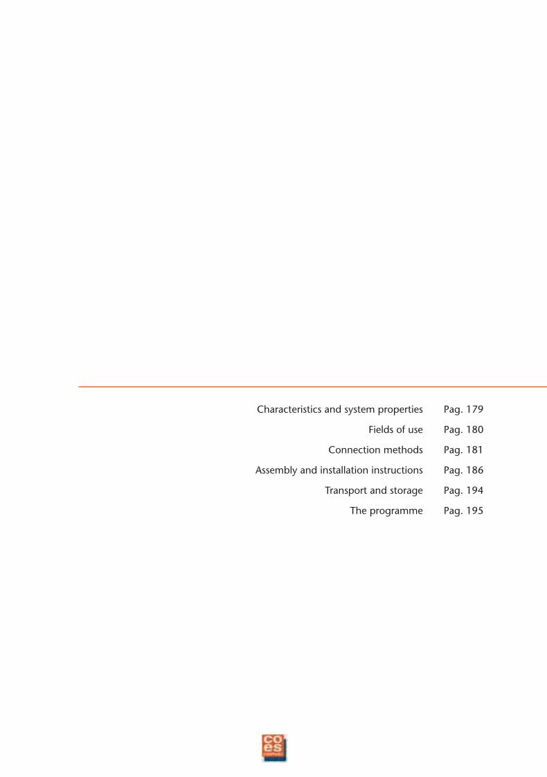
Coestherm® is a programme of pipes and fittings inrandom PP, from diam. 16 mm to diam. 125 mm, fortransporting fluids in the following fields of use:
Adduction of hot and cold water in sanitary, heatingand air conditioning systems.
Transport of chemicals and alimentary liquids inindustrial applications
Irrigation systems for greenhouses and gardens
Compressed air systems
Random PP is a high-performance plastic material. Itresists cracking, even under pressure, corrosion andchemicals. In addition, its molecular compositionguarantees acoustic insulation and immunity to groundcurrents.
The Coestherm® programme is non-toxic and perfectlysuitable for transporting drinking water and alimentaryliquids (Italian Ministerial Decree dated 6.04.04 nr. 174,ex-circular 102).
Coestherm® pipes are produced conforming to the DIN8077 standard; the fittings conform to DIN 16962 andtake into account a minimum operating period of 50years at pressures up to 10 bar with temperature of 60 °Cfor PN 20.
LOW HEAD LEAKS ANDHIGH THERMALSTABILITY
PERFECTLY WELDABLE
THE RAW MATERIAL ISNON-POLLUTING ANDRECYCLABLE
Coestherm®Coestherm®
02_ing_adduzione_e_riscald 9-02-2006 13:23 Pagina 178
179
CH
AR
AC
TER
ISTI
CS
AN
D S
YST
EM P
RO
PER
TIES
CHARACTERISTICS AND SYSTEM PROPERTIES
PHYSICAL CHARACTERISTICS
characteristics methods units valuesspecific weight ISO/R 1183 g/cm3 0,895fluidity indexat 190°C - with 5 kg
ISO 1133 g/10 min 0,4
fluidity indexat 230°C - with 2,16 kg
ISO 1133 g/10 min 0,3
melting pointpolarisation
°C 140-150microscope
THERMAL CHARACTERISTICS
characteristics methods units valuesthermal conductivityat 20°C
DIN 52612 W/m·K 0,24
specific heat at 20°Cadiabatic
KJ/Kg·K 2,0calorimeter
linear thermalexpansion coefficent VDE 0304 K–1 1,5×10⁻⁴
MECHANICAL CHARACTERISTICS
characteristics methods units valuesyield strength ISO/R527 N/mm2 21breaking load DIN 53455 N/mm2 40ultimate elongation DIN 53455 % 800coefficient of elasticity ISO 178 N/mm2 800hardness test ISO 2039 N/mm2 40resilience with test (Charpy)on uncut specimenat 0°C ISO 179 KJ/m2 it does not breakat –10°C KJ/m2 it does not breakresilience with test (Charpy)on uncut specimena 0°C ISO 179 KJ/m2 7a –10°C KJ/m2 3impact resistance at 0°C DIN 8078 it does not break
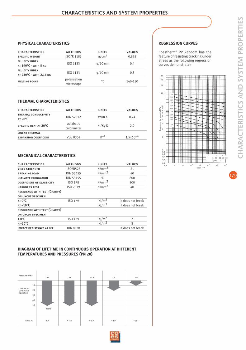
DIAGRAM OF LIFETIME IN CONTINUOUS OPERATION AT DIFFERENTTEMPERATURES AND PRESSURES (PN 20)
Pressure BARS20 20 12.6 7.8 5.9
Temp. °C
Years
50
40
30
20
10
20° ≤ 40° ≤ 60° ≤ 80° ≤ 95°
Lifetime incontinuousoperation
Dur
atio
n of
the
stre
ss in
MP
a
10
20
30
40
50
987
6
5
4
3
2
10,90,80,7
0,6
0,50,1 1 10 102 103 104 105 106
hours
years1 5 10 25 50 100
10°20°30°40°
50°60°
70°
80°90°95°
110°
REGRESSION CURVES
Coestherm® PP Random has thefeature of resisting cracking understress as the following regressioncurves demonstrate:
02_ing_adduzione_e_riscald 9-02-2006 13:23 Pagina 179
180
FIEL
DS
OF
USE
FIELDS OF USE
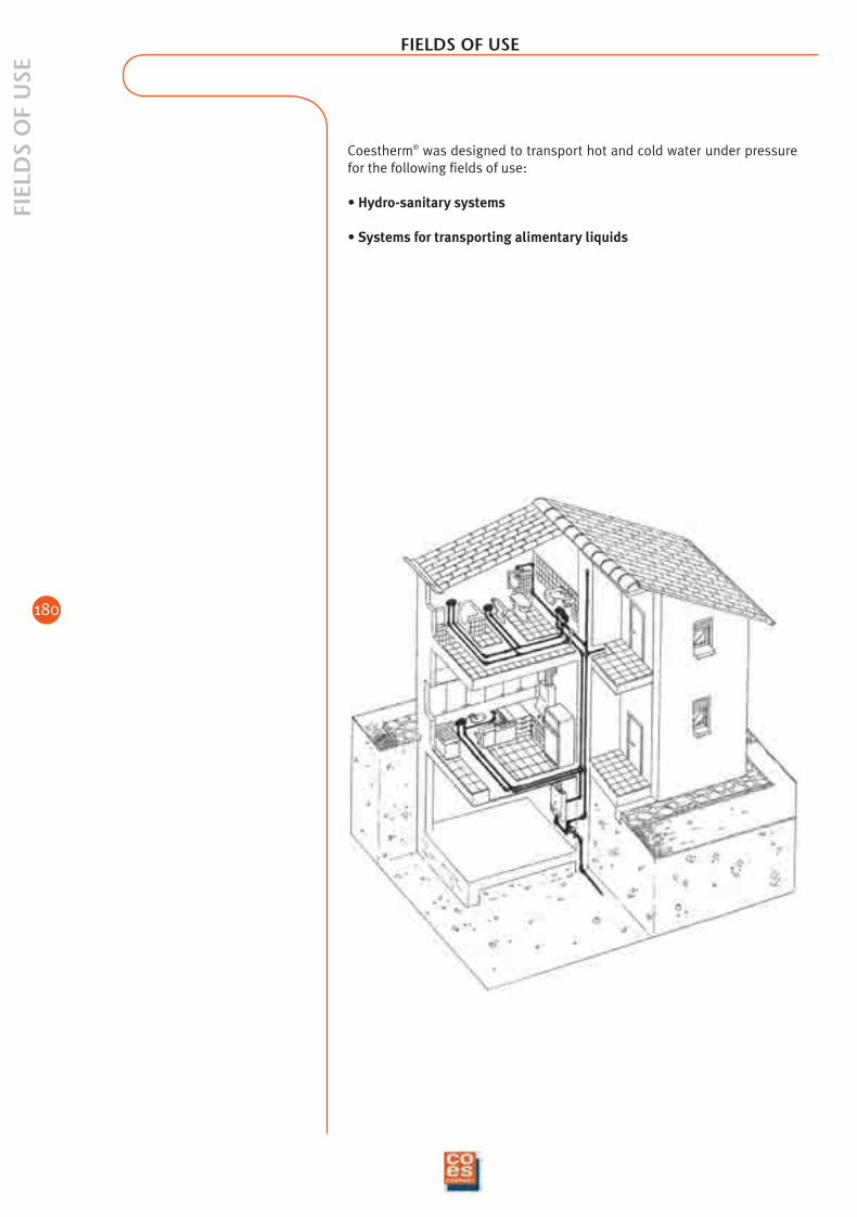
Coestherm® was designed to transport hot and cold water under pressurefor the following fields of use:
• Hydro-sanitary systems
• Systems for transporting alimentary liquids
02_ing_adduzione_e_riscald 9-02-2006 13:24 Pagina 180
181
CO
NN
ECTI
ON
MET
HO
DS
CONNECTION METHODS
CONNECTION TECHNIQUES
The Coestherm® connection technique is based on two systems: welding and mechanicalscrewing
Welding technique:Polyfusion Electric sleeveStar jointsStabi pipe
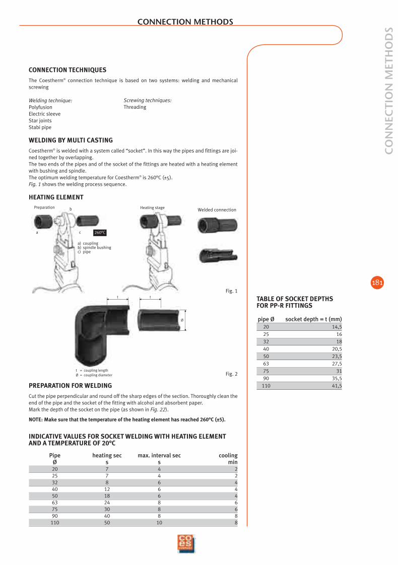
WELDING BY MULTI CASTING
Coestherm® is welded with a system called “socket”. In this way the pipes and fittings are joi-ned together by overlapping.The two ends of the pipes and of the socket of the fittings are heated with a heating elementwith bushing and spindle.The optimum welding temperature for Coestherm® is 260°C (±5).Fig. 1 shows the welding process sequence.
HEATING ELEMENT
Fig. 1
TABLE OF SOCKET DEPTHSFOR PP-R FITTINGS
pipe Ø socket depth = t (mm)20 14,525 1632 1840 20,550 23,563 27,575 3190 35,5
110 41,5
Ø
t = coupling lengthØ = coupling diameter
t t
Fig. 2
INDICATIVE VALUES FOR SOCKET WELDING WITH HEATING ELEMENTAND A TEMPERATURE OF 20°C
Pipe heating sec max. interval sec coolingØ s s min20 7 4 225 7 4 232 8 6 440 12 6 450 18 6 463 24 8 675 30 8 690 40 8 8
110 50 10 8
Heating stage
ushing
0°C
Welded connectionPreparation
a
b
c
a) couplingb) spindle bushingc) pipe
260°C
PREPARATION FOR WELDING
Cut the pipe perpendicular and round off the sharp edges of the section. Thoroughly clean theend of the pipe and the socket of the fitting with alcohol and absorbent paper. Mark the depth of the socket on the pipe (as shown in Fig. 22).
NOTE: Make sure that the temperature of the heating element has reached 260°C (±5).
Screwing techniques:Threading
02_ing_adduzione_e_riscald 9-02-2006 13:24 Pagina 181
182
CO
NN
ECTI
ON
MET
HO
DS
CONNECTION METHODS
Clean the end of the pipe and the socket of the fitting with alcohol and ab-sorbent paper. Mark the depth of the fitting’s insertion on the pipe (Fig. 2). Consult thedepth table for calculating the depth of the socket of the fittings with re-spect to the Ø.
Heat the pipe and fitting at the same time (as indicated in figure 3).
After the heating time has passed (Fig. 4 ), detach the pipe and fitting fromthe heating element at the same time.
Join the pipe and fitting without turning them within the allowable time(Fig. 5).
Fig. 1
Fig. 2
Fig. 3
Fig. 4
Fig. 5
MAKING THE WELDING
During this operation, pipe and fitting are held motionless, preventing themfrom turning. The pipe is quickly inserted axially into the bushing (up to themarking line on the socket), whereas the fitting is pushed all the way on thespindle. During this operation, pipe and fitting are held motionless withoutletting them turn. The surfaces to be joined are heated according to thetable (Fig. 23). After the heating time has passed, the pieces are extractedfrom the heating element and immediately joined axially without turningthem. You have to pay attention to the right coupling depth. The pipe mustbe inserted up to the previously marked point, meaning up to the bottom ofthe socket. It is advisable to continue keeping the two parts fixed for a cer-tain period of time (equivalent to approximately the heating time). Thewelded connection can be subjected to mechanical stress only after thecooling time has passed. The bushing and spindle have to be thoroughlycleaned after each welding operation.
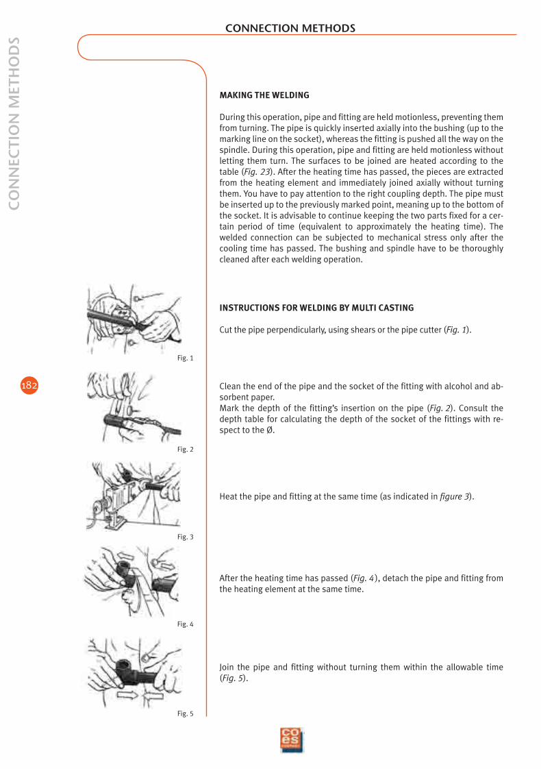
INSTRUCTIONS FOR WELDING BY MULTI CASTING
Cut the pipe perpendicularly, using shears or the pipe cutter (Fig. 1).
02_ing_adduzione_e_riscald 9-02-2006 13:24 Pagina 182

183
CO
NN
ECTI
ON
MET
HO
DS
CONNECTION METHODS
WELDING WITH ELECTRIC COUPLING
The electric coupling works according to a very simple principle. A properlysized heating element that can be connected to the coupling welding ma-chine with plug pins is inserted inside the coupling body using a special,exclusive Coes technology.All you have to do is connect the plug pins to the coupling welder, press“Start” and the current that flows through the electric coupling will developsuch a quantity of heat as to make the multi casting between fitting andpipe optimum.The Coestherm® electric coupling has a stop ring that can be disassembled.This solution lets us have a precise retainer when coupling the pipe, and isextremely useful for repairs. In fact, the coupling can freely slide over thepipe when the stop ring is removed.
INSTRUCTIONS FOR WELDING WITH ELECTRIC COUPLING
To get proper welding with the electric coupling, cut the pipe suitable andperpendicular to the axis (Fig. 1).
Scrape the surface of the pipe with a scraper to remove impurities.Clean the pipe and coupling with alcohol or a proprietary detergent (Fig. 2).
Insert the pipe observing the coupling depth.For this purpose mark the pipes with the special pencil so as to get exactcentring of the coupling and prevent any unthreading (Fig. 3).
During welding and consequent cooling stage, prevent all possible externalstresses for a minimum time of 4 minutes (Fig. 4).
Wait at least 2 hours (from the most recent welding) before putting the sys-tem under vacuum (Fig. 5).
90°
Fig. 1
Fig. 2
Fig. 3
Fig. 4
Fig. 5COUPLING BY THREADING
All of the metal inserts inserted into Coestherm® are made of OT 58 brass andthe threading is made in conformity with the ISO 228 and DIN 2999 standards.
02_ing_adduzione_e_riscald 9-02-2006 13:24 Pagina 183

184
CO
NN
ECTI
ON
MET
HO
DS
CONNECTION METHODS
Fig. 1
Fig. 2
Fig. 3
Fig. 4
Fig. 5
INSTRUCTIONS FOR WELDING COESTHERM® SADDLE JOINTS
Abide by the following instructions when welding the saddle joints of diam-eter 20, 25 and 32 (manual welding).Place the special matrixes on the multi caster (Fig. 1).
Mount the cutter of the desired diameter on a drill and drill the pipe in thepre-established point (Fig. 2).
Insert the matrix with white pin (Fig. 1) into the previously made hole and atthe same time set the saddle joint in the hollow matrix. Move the saddlejoint away from the matrix at the end of the heating stage and at the sametime remove the multi caster from the pipe (Fig. 3 ).
Set and centre the saddle joint a few seconds later, and keep it presseddown for about 30 sec. so that it creates an even 1.5-mm bead (Fig. 4).
It is advisable you use special equipment for the saddle joints of diameter40, 50, 63 and 75 so as to ensure the correct thrust force (Fig. 5 ). The sameequipment can also be used for welding diameters 20, 25 and 32.
02_ing_adduzione_e_riscald 9-02-2006 13:24 Pagina 184
185
CO
NN
ECTI
ON
MET
HO
DS
CONNECTION METHODS
Fig. 1
Fig. 2
Fig. 3
Fig. 4
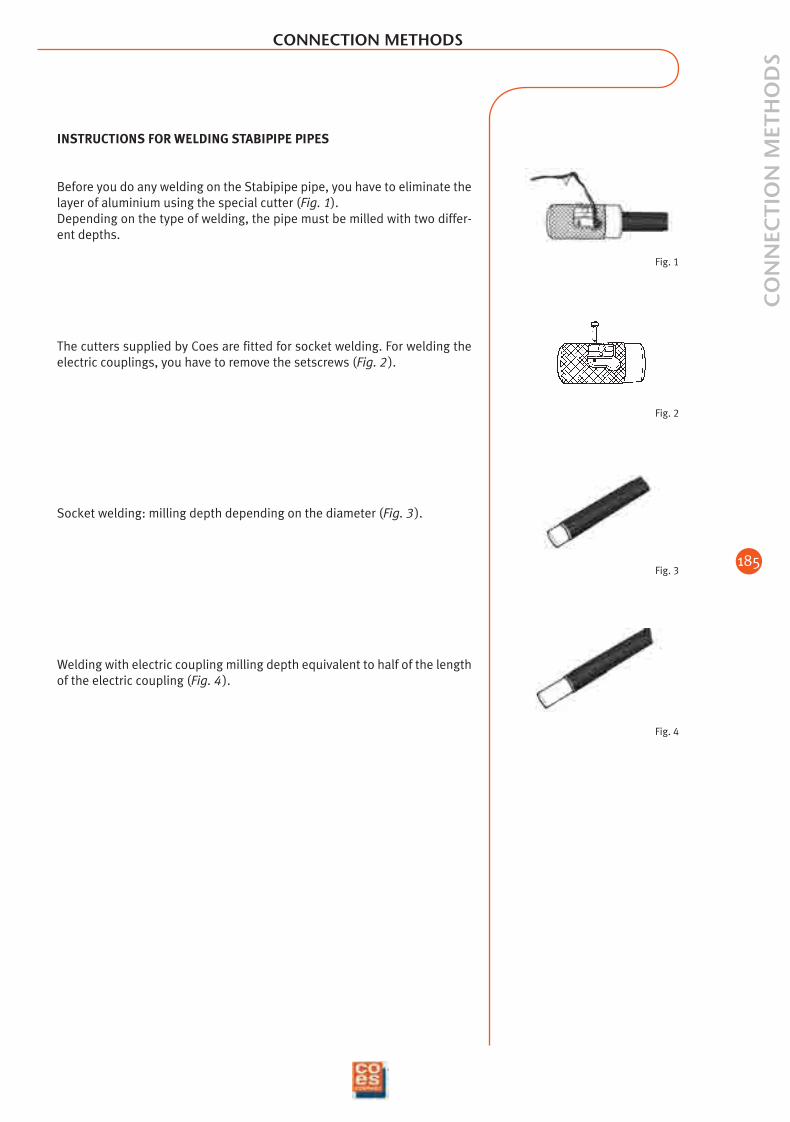
INSTRUCTIONS FOR WELDING STABIPIPE PIPES
Before you do any welding on the Stabipipe pipe, you have to eliminate thelayer of aluminium using the special cutter (Fig. 1).Depending on the type of welding, the pipe must be milled with two differ-ent depths.
The cutters supplied by Coes are fitted for socket welding. For welding theelectric couplings, you have to remove the setscrews (Fig. 2 ).
Socket welding: milling depth depending on the diameter (Fig. 3 ).
Welding with electric coupling milling depth equivalent to half of the lengthof the electric coupling (Fig. 4 ).
02_ing_adduzione_e_riscald 9-02-2006 13:24 Pagina 185
186
ASS
EMB
LY A
ND
INST
ALL
ATI
ON
INST
RU
CTI
ON
S
0.1 0,2 0,50,3
1 2 3 45 7 9
6 8 10 20 30 50 100 200 30040 400
500 1000 2000 4000 100003000 5000
0.001
0.002
0.0030.0040.005
0.01
0.02
0.030.040.05
0.1
0.2
0.30.40.5
1
2
345
10
20
304050
100
V · 0.1 m/s
V · 0.2 m/sV · 0.3 m/sV · 0.4 m/sV · 0.5 m/sV · 0.6 m/sV · 0.7 m/sV · 0.8 m/sV · 0.9 m/s
V · 1 m/sV · 1.2 m/sV · 1.4 m/sV · 1.6 m/sV · 1.8 m/s
V · 2 m/sV · 2.5 m/s
V · 3 m/s Ø 110 Ø 90
Ø 75
Ø 63
Ø 50
Ø 40
Ø 32
Ø 25
Ø 20
Ø 16
ASSEMBLY AND INSTALLATION INSTRUCTIONS
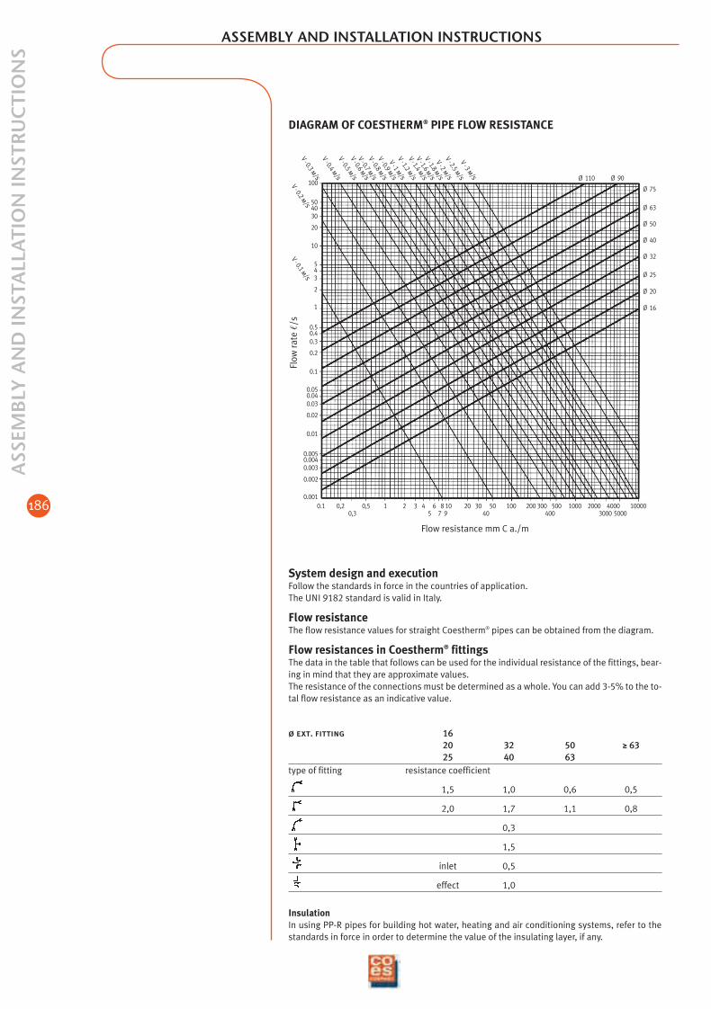
DIAGRAM OF COESTHERM® PIPE FLOW RESISTANCE
Flow
rate
/s
Flow resistance mm C a./m
System design and executionFollow the standards in force in the countries of application.The UNI 9182 standard is valid in Italy.
Flow resistanceThe flow resistance values for straight Coestherm® pipes can be obtained from the diagram.
Flow resistances in Coestherm® fittingsThe data in the table that follows can be used for the individual resistance of the fittings, bear-ing in mind that they are approximate values.The resistance of the connections must be determined as a whole. You can add 3-5% to the to-tal flow resistance as an indicative value.
ø ext. fitting 1620 32 50 ≥ 6325 40 63
type of fitting resistance coefficient
1,5 1,0 0,6 0,5
2,0 1,7 1,1 0,8
0,3
1,5
inlet 0,5
effect 1,0
InsulationIn using PP-R pipes for building hot water, heating and air conditioning systems, refer to thestandards in force in order to determine the value of the insulating layer, if any.
02_ing_adduzione_e_riscald 9-02-2006 13:24 Pagina 186
187
ASS
EMB
LY A
ND
INST
ALL
ATI
ON
INST
RU
CTI
ON
S
ASSEMBLY AND INSTALLATION INSTRUCTIONS
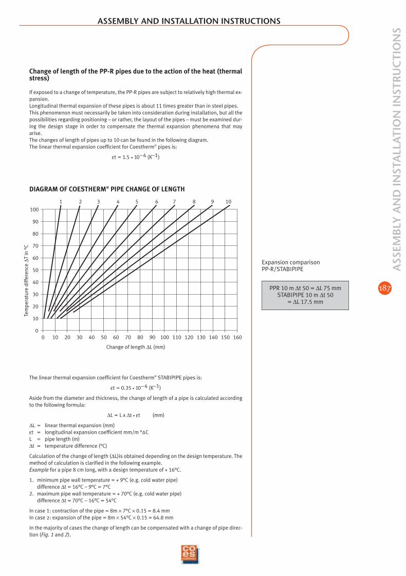
Change of length of the PP-R pipes due to the action of the heat (thermalstress)
If exposed to a change of temperature, the PP-R pipes are subject to relatively high thermal ex-pansion.Longitudinal thermal expansion of these pipes is about 11 times greater than in steel pipes.This phenomenon must necessarily be taken into consideration during installation, but all thepossibilities regarding positioning – or rather, the layout of the pipes – must be examined dur-ing the design stage in order to compensate the thermal expansion phenomena that mayarise.The changes of length of pipes up to 10 can be found in the following diagram.The linear thermal expansion coefficient for Coestherm® pipes is:
εt = 1.5 • 10–4 (K–1)
1 2 3 4 5 6 7 8 9 10
0
10
20
30
40
50
60
70
80
90
100
30 1600 10 20 15040 50 80 90 100 110 120 130 1407060
DIAGRAM OF COESTHERM® PIPE CHANGE OF LENGTH
Change of length ∆L (mm)
Expansion comparisonPP-R/STABIPIPE
PPR 10 m ∆t 50 = ∆L 75 mmSTABIPIPE 10 m ∆t 50
= ∆L 17.5 mm
The linear thermal expansion coefficient for Coestherm® STABIPIPE pipes is:
εt = 0.35 • 10–4 (K–1)
Aside from the diameter and thickness, the change of length of a pipe is calculated accordingto the following formula:
∆L = L x ∆t • εt (mm)
∆L = linear thermal expansion (mm)εt = longitudinal expansion coefficient mm/m °∆CL = pipe length (m)∆t = temperature difference (°C)
Calculation of the change of length (∆L)is obtained depending on the design temperature. Themethod of calculation is clarified in the following example.Example for a pipe 8 cm long, with a design temperature of + 16°C.
1. minimum pipe wall temperature = + 9°C (e.g. cold water pipe) difference ∆t = 16°C – 9°C = 7°C
2. maximum pipe wall temperature = + 70°C (e.g. cold water pipe) difference ∆t = 70°C – 16°C = 54°C
In case 1: contraction of the pipe = 8m × 7°C × 0.15 = 8.4 mmIn case 2: expansion of the pipe = 8m × 54°C × 0.15 = 64.8 mm
In the majority of cases the change of length can be compensated with a change of pipe direc-tion (Fig. 1 and 2).
Tem
pera
ture
diff
eren
ce ∆
Tin
°C
02_ing_adduzione_e_riscald 9-02-2006 13:25 Pagina 187

188
ASS
EMB
LY A
ND
INST
ALL
ATI
ON
INST
RU
CTI
ON
S ASSEMBLY AND INSTALLATION INSTRUCTIONS
PF = fixed point
PS = sliding point
L = length
∆L = Change of length
Ls = length of the arm startingfrom the fixed point
Ls1
Ls
∆L1
PF PS
PF
PF = fixed point
PS = sliding point
∆L1 = changes of length
Ls = length of the arm startingfrom the fixed point
Ls1 = length of the arm startingfrom the sliding point
EXPANSION COMPENSATION BY CHANGE OF DIRECTION
You have to make sure that the pipe can move freely in an axial direction, and in this case ifcompensation by change of direction is not possible, you have to install expansion curves.Generally speaking, axial compensators are not suitable for the purpose and moreover, theyare not economic. You have to calculate the length of the flexible arm of the pipe by using theformula that follows in order to achieve compensation:
Ls = K • (mm)
where: Ls = length of the arm (mm)d = external diameter of the pipe (mm)∆L = change of length (mm)K = constant depending on the material used (for PP = 20).
The compensation systems depending on the linear expansion are illustrated in the diagramsof Fig. 1, 2 and 3.
d • ∆L
Having defined the stretch of pipe L, we calculate ∆L with the formula:
∆L = L • ∆t • εt
from which we get the length of the flexible arm and the position where the bracket is to beinstalled for the fixed point with the formula:
Ls = K d • ∆L
Fig. 1
L
Ls
∆L
PF PS
PF
Fig. 2
02_ing_adduzione_e_riscald 9-02-2006 13:25 Pagina 188
189
ASS
EMB
LY A
ND
INST
ALL
ATI
ON
INST
RU
CTI
ON
S
∆L/2
PF PF
L
∆L/2
Ø
L2
L1
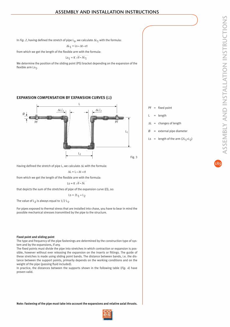
PF = fixed point
L = length
∆L = changes of length
Ø = external pipe diameter
Ls = length of the arm (2L1+L2)
Fig. 3
Having defined the stretch of pipe L, we calculate ∆L with the formula:
∆L = L • ∆t • εt
from which we get the length of the flexible arm with the formula:
Ls = K
that depicts the sum of the stretches of pipe of the expansion curve (Ω), so:
Ls = 2L1 + L2
The value of L2 is always equal to 1/2 L1.
For pipes exposed to thermal stress that are installed into chase, you have to bear in mind thepossible mechanical stresses transmitted by the pipe to the structure.
d • ∆L
Fixed point and sliding pointThe type and frequency of the pipe fastenings are determined by the construction type of sys-tem and by the expansions, if any.The fixed points must divide the pipe into stretches in which contraction or expansion is pos-sible, however without ever releasing the expansion on the inserts or fittings. The guide ofthese stretches is made using sliding point bands. The distance between bands, i.e. the dis-tance between the support points, primarily depends on the working conditions and on theweight of the pipe (passing fluid included).In practice, the distances between the supports shown in the following table (Fig. 4) haveproven valid.
In Fig. 2, having defined the stretch of pipe Ls, we calculate ∆L1 with the formula:
∆L1 = Ls • ∆t • εt
from which we get the length of the flexible arm with the formula:
Ls1 = K
We determine the position of the sliding point (PS) bracket depending on the expansion of theflexible arm Ls1.
d • ∆L1
Note: Fastening of the pipe must take into account the expansions and relative axial thrusts.
ASSEMBLY AND INSTALLATION INSTRUCTIONS
EXPANSION COMPENSATION BY EXPANSION CURVES (Ω)
02_ing_adduzione_e_riscald 9-02-2006 13:25 Pagina 189
190
ASS
EMB
LY A
ND
INST
ALL
ATI
ON
INST
RU
CTI
ON
S ASSEMBLY AND INSTALLATION INSTRUCTIONS
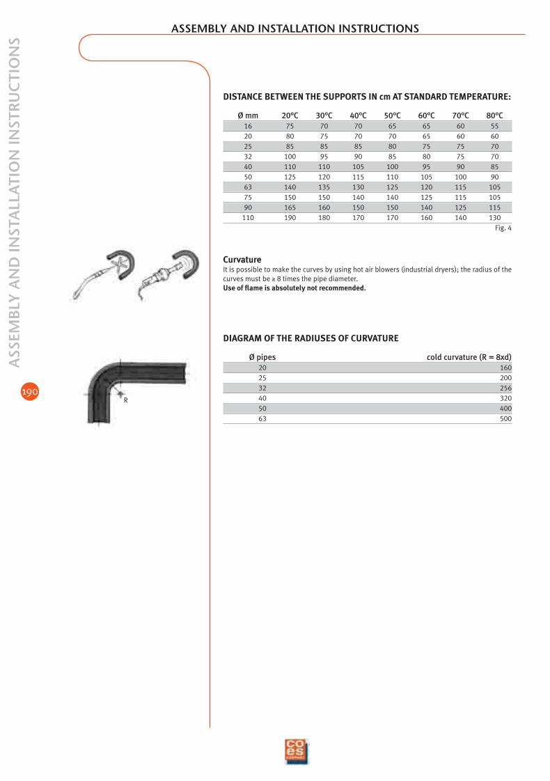
DISTANCE BETWEEN THE SUPPORTS IN cm AT STANDARD TEMPERATURE:
Ø mm 20°C 30°C 40°C 50°C 60°C 70°C 80°C16 75 70 70 65 65 60 5520 80 75 70 70 65 60 6025 85 85 85 80 75 75 7032 100 95 90 85 80 75 7040 110 110 105 100 95 90 8550 125 120 115 110 105 100 9063 140 135 130 125 120 115 10575 150 150 140 140 125 115 10590 165 160 150 150 140 125 115
110 190 180 170 170 160 140 130Fig. 4
CurvatureIt is possible to make the curves by using hot air blowers (industrial dryers); the radius of thecurves must be ≥ 8 times the pipe diameter.Use of flame is absolutely not recommended.
DIAGRAM OF THE RADIUSES OF CURVATURE
Ø pipes cold curvature (R = 8xd)20 16025 20032 25640 32050 40063 500
R
02_ing_adduzione_e_riscald 9-02-2006 13:25 Pagina 190
191
ASS
EMB
LY A
ND
INST
ALL
ATI
ON
INST
RU
CTI
ON
S
ASSEMBLY AND INSTALLATION INSTRUCTIONS
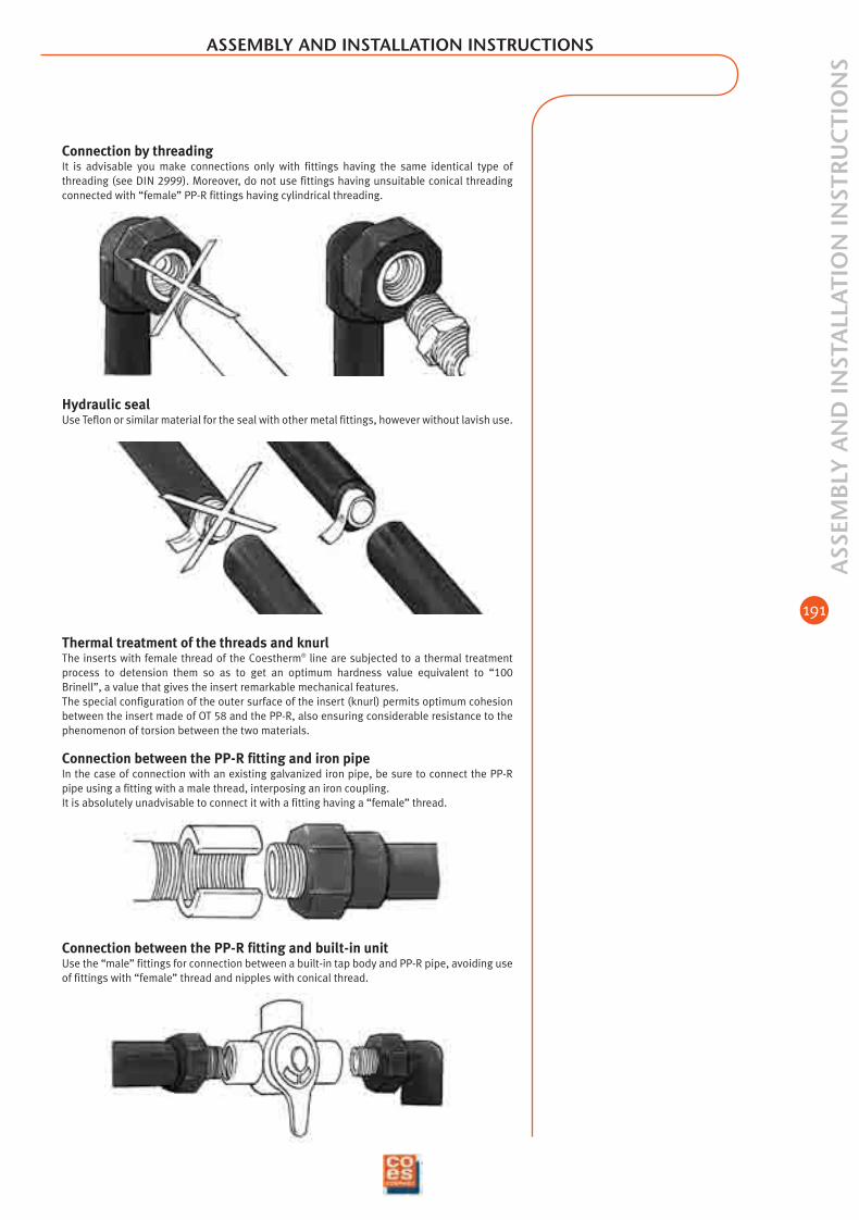
Connection between the PP-R fitting and built-in unitUse the “male” fittings for connection between a built-in tap body and PP-R pipe, avoiding useof fittings with “female” thread and nipples with conical thread.
Thermal treatment of the threads and knurlThe inserts with female thread of the Coestherm® line are subjected to a thermal treatmentprocess to detension them so as to get an optimum hardness value equivalent to “100Brinell”, a value that gives the insert remarkable mechanical features.The special configuration of the outer surface of the insert (knurl) permits optimum cohesionbetween the insert made of OT 58 and the PP-R, also ensuring considerable resistance to thephenomenon of torsion between the two materials.
Connection between the PP-R fitting and iron pipeIn the case of connection with an existing galvanized iron pipe, be sure to connect the PP-Rpipe using a fitting with a male thread, interposing an iron coupling.It is absolutely unadvisable to connect it with a fitting having a “female” thread.
Hydraulic sealUse Teflon or similar material for the seal with other metal fittings, however without lavish use.
Connection by threadingIt is advisable you make connections only with fittings having the same identical type ofthreading (see DIN 2999). Moreover, do not use fittings having unsuitable conical threadingconnected with “female” PP-R fittings having cylindrical threading.
02_ing_adduzione_e_riscald 9-02-2006 13:25 Pagina 191

192
Position the bracket complete with polystyrene in the wall excavation at theenvisaged heights or in the position indicated by the installer.
The surface plates of the bracket (transversal and longitudinal) must beperfectly calibrated. For this purpose use a water level and the speciallyprovided support appendices provided on the polystyrene mould as pointsof reference.
The installation depth must be about 56 mm from the finished surface(complete with covering). The exact reference is given by the reductionshown on the polystyrene. Secure the bracket (with mortar) in the centrepart and on the sides beside the two polystyrene cylinders while beingcareful to not obstruct the vertical passages (above and below).
Remove the polystyrene protection only when you insert the octagonal fit-tings. Prevent foreign bodies from getting into the seats.A perfect housing of the fittings in the seats is essential for good installa-tion.
Insert the fittings as shown in the figure. Then lock them with the relevantoctagonal ring nut, making its rounded part coincide with the cylindricalpart of the fitting.
When the job is completed, the finished surface will coincide with the ex-ternal faces of the two fittings. The threaded parts will face the establishedcentre distance and be aligned for fixing the fittings.
ASS
EMB
LY A
ND
INST
ALL
ATI
ON
INST
RU
CTI
ON
S ASSEMBLY AND INSTALLATION INSTRUCTIONS
02_ing_adduzione_e_riscald 9-02-2006 13:25 Pagina 192

193
ASS
EMB
LY A
ND
INST
ALL
ATI
ON
INST
RU
CTI
ON
S
ASSEMBLY AND INSTALLATION INSTRUCTIONS
Hole RepairIn the case you make a hole in a PP-R pipe, it is possi-ble to repair it by using the special tool to be mountedon the multi caster and the special hole repair patch(Fig. 1).
Changing the insertShould the female Ø 1/2” insert accidentally break, itis not necessary to remove the fitting – breaking tilesand masonry – but it is possible to avoid all of this byusing the special repair KIT and replacing only thethreaded ring nut (Fig. 2). Fig. 2
Fig. 1
Using the bracketIn order to make execution of PP-R systems simpler and more effective, Coes has de-signed and patented the bracket for fixed point for securing threaded terminals.
1 Screw on the bored 1/2” pawl (1) on the insert to be replaced.2 Mark the depth of the insert, 18 mm, with chalk on the hole saw (2) and cut, pivoting in the
hole.3 Set the extended matrix (3) on the insert for heating.4 To make extraction of the pawl to be replaced easier, use a 1/2” bar of pipe threaded on
one side (4).5 Plane the bottom of the fitting with the mill (5), holding the drill forcefully until the four
protuberances on the bottom have reached a thickness of about 0.5-1 mm6 Thoroughly clean the surfaces to be welded with alcohol.7 Heat the fitting with the extended male matrix.8 Screw the new insert (8) on a 1/2” bar of pipe and heat it with the female matrix D 32 for
about 7/8 seconds.9 Weld while pushing the insert down to the bottom of the fitting.
10 Before connecting to the thread, the welding must be completely cold.
Note: CO.E.S. S.p.A. declines all responsibility for damages caused by non-observance of allthe operations described above and/or by welding done with unsuitable equipment.
1
2
5
4
3
6
7
8
9
10
02_ing_adduzione_e_riscald 9-02-2006 13:25 Pagina 193
194
TRA
NSP
OR
T A
ND
STO
RA
GE
TRANSPORT AND STORAGE
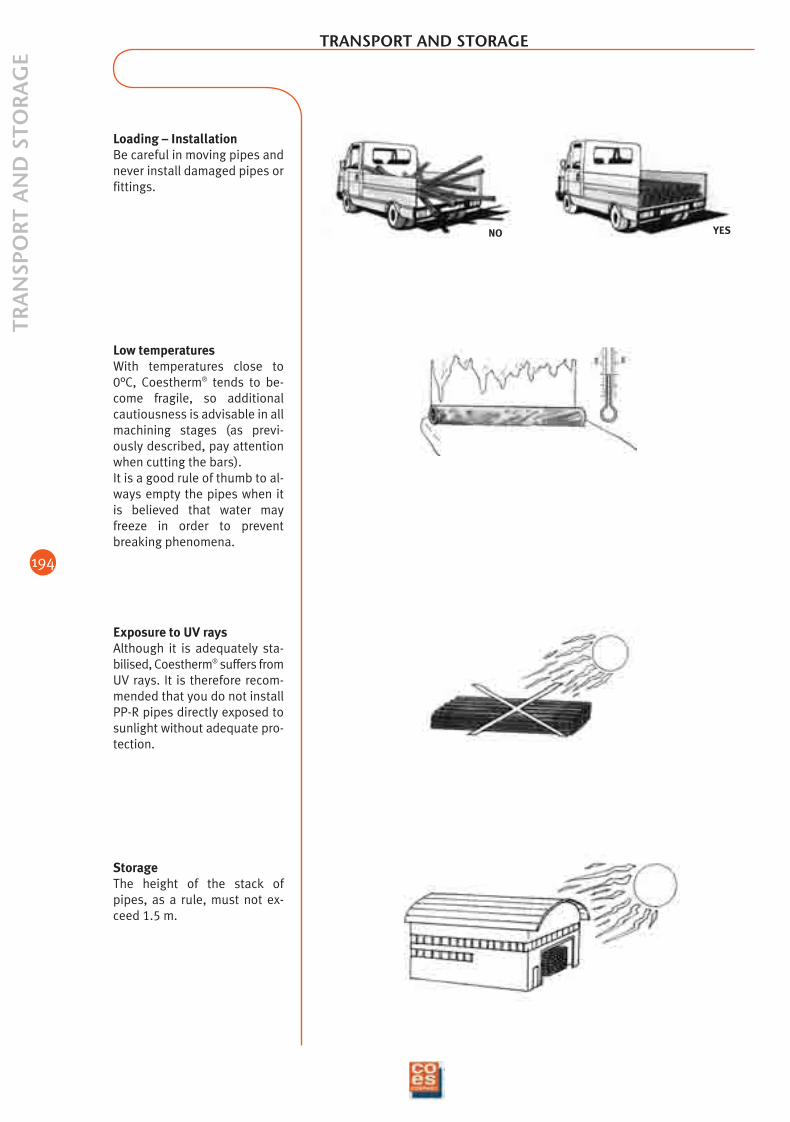
StorageThe height of the stack ofpipes, as a rule, must not ex-ceed 1.5 m.
Low temperaturesWith temperatures close to0°C, Coestherm® tends to be-come fragile, so additionalcautiousness is advisable in allmachining stages (as previ-ously described, pay attentionwhen cutting the bars).It is a good rule of thumb to al-ways empty the pipes when itis believed that water mayfreeze in order to preventbreaking phenomena.
Exposure to UV raysAlthough it is adequately sta-bilised, Coestherm® suffers fromUV rays. It is therefore recom-mended that you do not installPP-R pipes directly exposed tosunlight without adequate pro-tection.
YESNO
Loading – InstallationBe careful in moving pipes andnever install damaged pipes orfittings.
02_ing_adduzione_e_riscald 9-02-2006 13:25 Pagina 194
195
PP R
AN
DO
M P
IPES
THE PROGRAMME
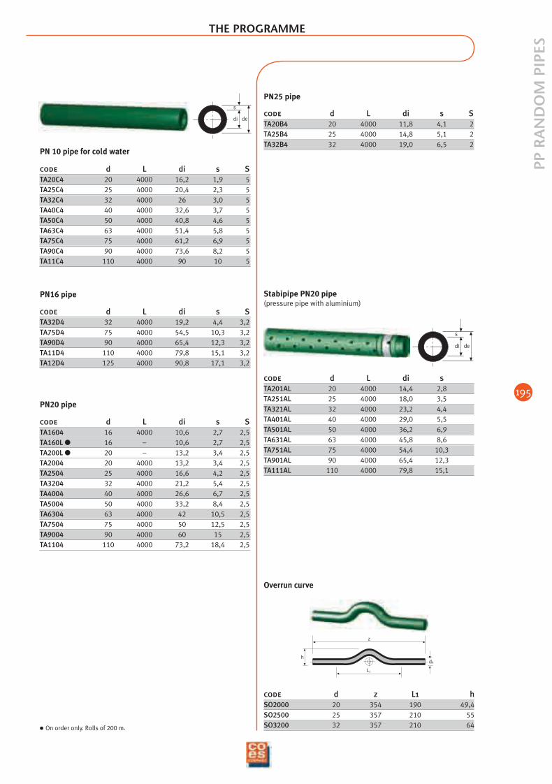
code d L di s STA20C4 20 4000 16,2 1,9 5TA25C4 25 4000 20,4 2,3 5TA32C4 32 4000 26 3,0 5TA40C4 40 4000 32,6 3,7 5TA50C4 50 4000 40,8 4,6 5TA63C4 63 4000 51,4 5,8 5TA75C4 75 4000 61,2 6,9 5TA90C4 90 4000 73,6 8,2 5TA11C4 110 4000 90 10 5
code d L di s STA32D4 32 4000 19,2 4,4 3,2TA75D4 75 4000 54,5 10,3 3,2TA90D4 90 4000 65,4 12,3 3,2TA11D4 110 4000 79,8 15,1 3,2TA12D4 125 4000 90,8 17,1 3,2
PN 10 pipe for cold water
dedi
s
code d L di s STA1604 16 4000 10,6 2,7 2,5TA160L 16 – 10,6 2,7 2,5TA200L 20 – 13,2 3,4 2,5TA2004 20 4000 13,2 3,4 2,5TA2504 25 4000 16,6 4,2 2,5TA3204 32 4000 21,2 5,4 2,5TA4004 40 4000 26,6 6,7 2,5TA5004 50 4000 33,2 8,4 2,5TA6304 63 4000 42 10,5 2,5TA7504 75 4000 50 12,5 2,5TA9004 90 4000 60 15 2,5TA1104 110 4000 73,2 18,4 2,5
dedi
s
code d L di sTA201AL 20 4000 14,4 2,8TA251AL 25 4000 18,0 3,5TA321AL 32 4000 23,2 4,4TA401AL 40 4000 29,0 5,5TA501AL 50 4000 36,2 6,9TA631AL 63 4000 45,8 8,6TA751AL 75 4000 54,4 10,3TA901AL 90 4000 65,4 12,3TA111AL 110 4000 79,8 15,1
Stabipipe PN20 pipe(pressure pipe with aluminium)
L1
z
hda
code d z L1 hSO2000 20 354 190 49,4SO2500 25 357 210 55SO3200 32 357 210 64
Overrun curve
PN20 pipe
PN16 pipe
code d L di s STA20B4 20 4000 11,8 4,1 2TA25B4 25 4000 14,8 5,1 2TA32B4 32 4000 19,0 6,5 2
PN25 pipe
On order only. Rolls of 200 m.
02_ing_adduzione_e_riscald 9-02-2006 13:25 Pagina 195
196
PP R
AN
DO
M F
ITTI
NG
S PN
25THE PROGRAMME
Dd
Z
L
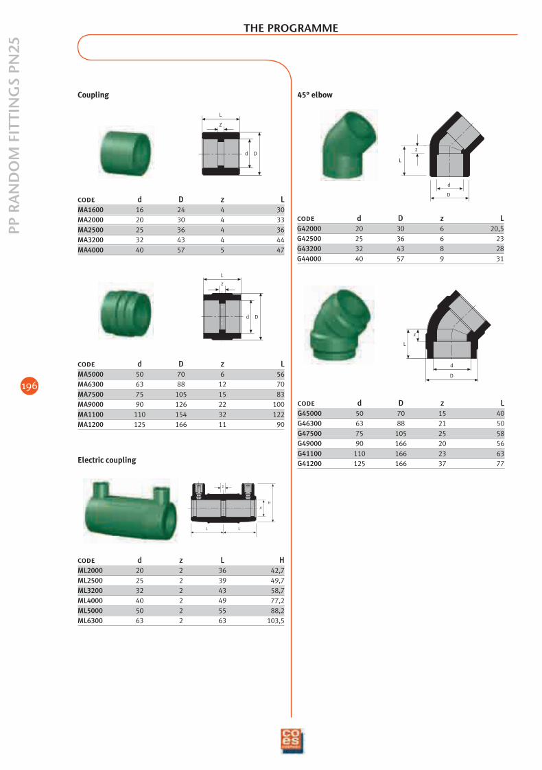
code d D z LMA1600 16 24 4 30MA2000 20 30 4 33MA2500 25 36 4 36MA3200 32 43 4 44MA4000 40 57 5 47
Coupling
d D
z
L
code d D z LMA5000 50 70 6 56MA6300 63 88 12 70MA7500 75 105 15 83MA9000 90 126 22 100MA1100 110 154 32 122MA1200 125 166 11 90
L L
dH
z
code d z L HML2000 20 2 36 42,7ML2500 25 2 39 49,7ML3200 32 2 43 58,7ML4000 40 2 49 77,2ML5000 50 2 55 88,2ML6300 63 2 63 103,5
Electric coupling
D
d
z
L
code d D z LG45000 50 70 15 40G46300 63 88 21 50G47500 75 105 25 58G49000 90 166 20 56G41100 110 166 23 63G41200 125 166 37 77
D
d
L
z
45° elbow
code d D z LG42000 20 30 6 20,5G42500 25 36 6 23G43200 32 43 8 28G44000 40 57 9 31
02_ing_adduzione_e_riscald 9-02-2006 13:25 Pagina 196
197
PP R
AN
DO
M F
ITTI
NG
S PN
25
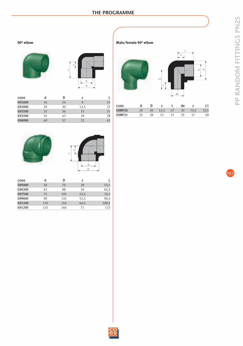
Male/female 90° elbow
d
D
zL
code d D z LG95000 50 70 28 53,5G96300 63 88 36 65,5G97500 75 105 43,5 76,5G99000 90 126 52,5 90,5G91100 110 154 64,5 108,5G91200 125 166 71 122
Dd
L
z
L1
c
de
code d D z L de c L1G9MF20 20 30 12,5 27 20 15,5 33,5G9MF25 25 38 15 31 25 17 40
L
z
d
D
code d D z LG91600 16 24 9 22G92000 20 30 12,5 27G92500 25 36 15 31G93200 32 43 18 38G94000 40 57 22 43
90° elbow
THE PROGRAMME
02_ing_adduzione_e_riscald 9-02-2006 13:25 Pagina 197
198
PP R
AN
DO
M F
ITTI
NG
S PN
25THE PROGRAMME
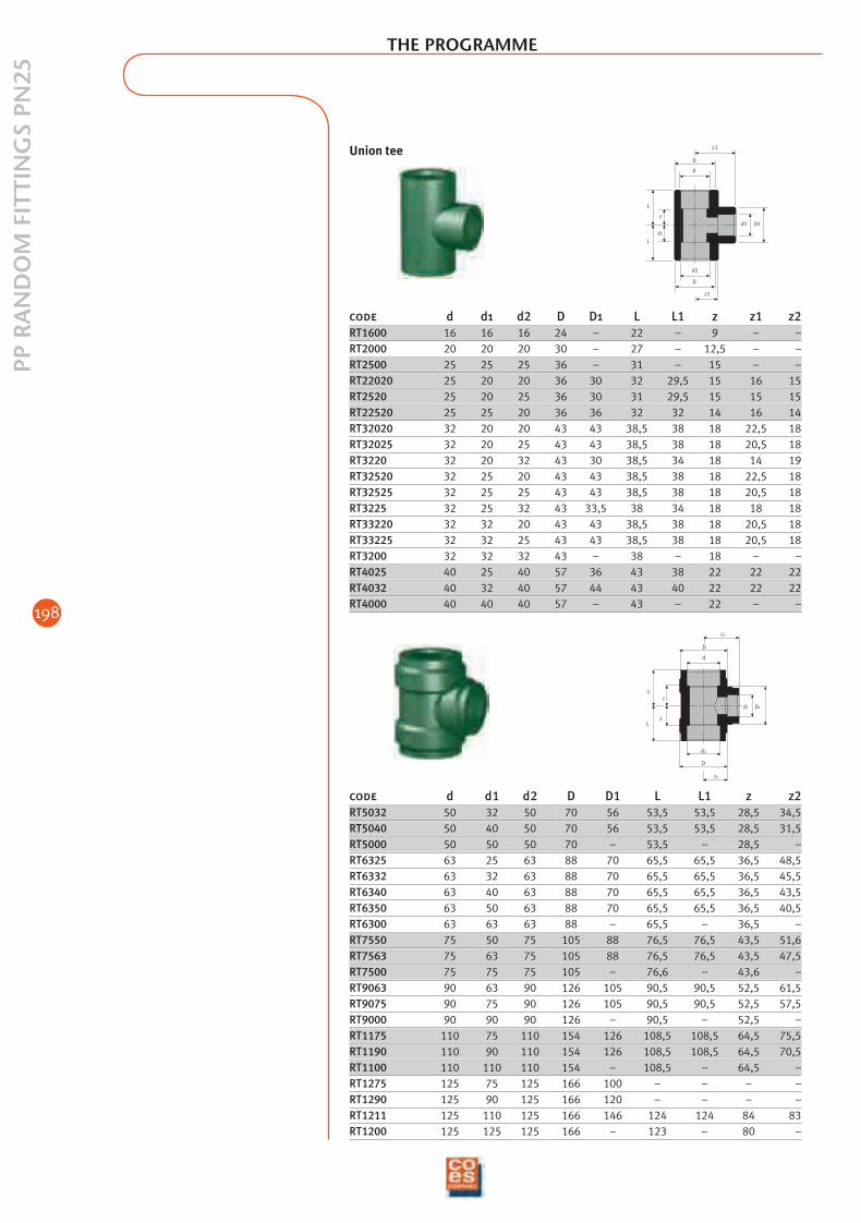
code d d1 d2 D D1 L L1 z z2RT5032 50 32 50 70 56 53,5 53,5 28,5 34,5RT5040 50 40 50 70 56 53,5 53,5 28,5 31,5RT5000 50 50 50 70 – 53,5 – 28,5 –RT6325 63 25 63 88 70 65,5 65,5 36,5 48,5RT6332 63 32 63 88 70 65,5 65,5 36,5 45,5RT6340 63 40 63 88 70 65,5 65,5 36,5 43,5RT6350 63 50 63 88 70 65,5 65,5 36,5 40,5RT6300 63 63 63 88 – 65,5 – 36,5 –RT7550 75 50 75 105 88 76,5 76,5 43,5 51,6RT7563 75 63 75 105 88 76,5 76,5 43,5 47,5RT7500 75 75 75 105 – 76,6 – 43,6 –RT9063 90 63 90 126 105 90,5 90,5 52,5 61,5RT9075 90 75 90 126 105 90,5 90,5 52,5 57,5RT9000 90 90 90 126 – 90,5 – 52,5 –RT1175 110 75 110 154 126 108,5 108,5 64,5 75,5RT1190 110 90 110 154 126 108,5 108,5 64,5 70,5RT1100 110 110 110 154 – 108,5 – 64,5 –RT1275 125 75 125 166 100 – – – –RT1290 125 90 125 166 120 – – – –RT1211 125 110 125 166 146 124 124 84 83RT1200 125 125 125 166 – 123 – 80 –
code d d1 d2 D D1 L L1 z z1 z2RT1600 16 16 16 24 – 22 – 9 – –RT2000 20 20 20 30 – 27 – 12,5 – –RT2500 25 25 25 36 – 31 – 15 – –RT22020 25 20 20 36 30 32 29,5 15 16 15RT2520 25 20 25 36 30 31 29,5 15 15 15RT22520 25 25 20 36 36 32 32 14 16 14RT32020 32 20 20 43 43 38,5 38 18 22,5 18RT32025 32 20 25 43 43 38,5 38 18 20,5 18RT3220 32 20 32 43 30 38,5 34 18 14 19RT32520 32 25 20 43 43 38,5 38 18 22,5 18RT32525 32 25 25 43 43 38,5 38 18 20,5 18RT3225 32 25 32 43 33,5 38 34 18 18 18RT33220 32 32 20 43 43 38,5 38 18 20,5 18RT33225 32 32 25 43 43 38,5 38 18 20,5 18RT3200 32 32 32 43 – 38 – 18 – –RT4025 40 25 40 57 36 43 38 22 22 22RT4032 40 32 40 57 44 43 40 22 22 22RT4000 40 40 40 57 – 43 – 22 – –
L
L
z1
z
D
d2
D
z2
d
L1
D1d1
z
z
L
L
d2
D
d
D
z2
d1 D1
L1
Union tee
02_ing_adduzione_e_riscald 9-02-2006 13:26 Pagina 198
199
PP R
AN
DO
M F
ITTI
NG
S PN
25
d D
L
z
de
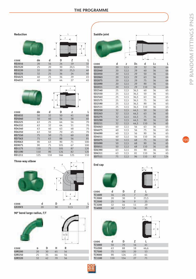
Reduction
z
L
D d de
code de d D z LRD5032 50 32 50 41 60RD5040 50 40 56 38 60RD6325 63 25 64 54 70RD6332 63 32 64 51 70RD6340 63 40 63 48 70RD6350 63 50 70 45 70RD7550 75 50 75 60 85RD7563 75 63 88 56 85RD9063 90 63 90 71 100RD9075 90 75 105 67 100RD1175 110 75 105 87 120RD1190 110 90 126 82 120RD1211 125 110 166 125 110
L
Z
D
d
L
z
D
d
Three-way elbow
code d D H RG9R200 20 30 65 56G9R250 25 35 66 56G9R320 32 42 70 56
90° bend large radius, f/f
L
d L1
D1 d
z
code d z D1 d L1 LSD2032 20 12,5 29 32 36 64SD2040 20 12,5 29 40 36 64SD2050 20 12,5 29 50 36 64SD2063 20 12,5 29 63 36 64SD2075 20 12,5 29 75 36 64SD2090 20 12,5 29 90 36 64SD2011 20 12,5 29 110 36 64SD2540 25 12,5 36,5 40 36 65SD2550 25 12,5 36,5 50 36 65SD2563 25 12,5 36,5 63 36 65SD2575 25 12,5 36,5 75 36 65SD2590 25 12,5 36,5 90 36 65SD2511 25 12,5 36,5 110 36 65SD3250 32 12,5 44,5 50 36 65SD3263 32 12,5 44,5 63 36 65SD3275 32 12,5 44,5 75 36 65SD3290 32 12,5 44,5 90 36 65SD3211 32 12,5 44,5 110 36 65SD4063 40 12,5 56 63 36 65SD4075 40 12,5 56 75 36 65SD4090 40 12,5 56 90 36 65SD4011 40 12,5 56 110 36 65SD5075 50 12,5 68 75 36 65SD5090 50 12,5 68 90 36 65SD5011 50 12,5 68 110 36 65SD6390 63 12,5 81 90 36 65SD6311 63 12,5 81 110 36 65SD7511 75 12,5 96 110 82 124
Saddle joint
code de d D Z LRD2016 20 16 24 19 32RD2520 25 20 30 20,5 35RD3220 32 20 30 25,5 40RD3225 32 25 36 24 40RD4025 40 25 36 29 45RD4032 40 32 44 27 45
code d D z LG920V3 20 30 12,5 27
THE PROGRAMME
Lz
Dd
Lz
d D
code d D Z LTC5000 50 70 16 41TC6300 63 88 18 46,6TC7500 75 105 20 53TC9000 90 126 23 61TC1100 110 154 27 71
End cap
code d D Z LTC1600 16 24 7 20TC2000 20 30 9 23,5TC2500 25 36 9 25TC3200 32 44 11 29TC4000 40 57 14 35
02_ing_adduzione_e_riscald 9-02-2006 13:26 Pagina 199
200
PP R
AN
DO
M F
ITTI
NG
S PN
25THE PROGRAMME
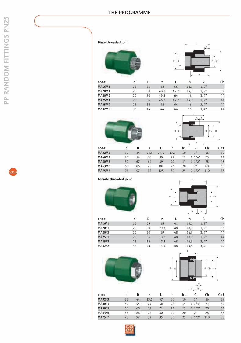
code d D z L h R ChMA16M1 16 35 43 56 14,7 1/2” -MA20M1 20 30 48,2 62,7 14,7 1/2” 37MA20M2 20 30 49,5 64 16 3/4” 44MA25M1 25 36 46,7 62,7 14,7 1/2” 44MA25M2 25 36 48 64 16 3/4” 44MA32M2 32 44 44 64 16 3/4” 44
D d
z
ChR
L
h
h1
dD R ChCh1
h
L
z
code d D z L h h1 R Ch Ch1MA32M3 32 44 54,5 74,5 17,5 10 1” 56 39MA40M4 40 54 68 90 22 15 1 1/4” 73 44MA50M5 50 67 64 89 20 13 1 1/2” 78 48MA63M6 63 86 75 104 24 20 2” 88 60MA75M7 75 97 92 125 30 25 2 1/2” 110 78
D d G Ch
z h
L
code d D z L h G ChMA16F1 16 35 15 41 13,2 1/2” -MA20F1 20 30 20,3 48 13,2 1/2” 37MA20F2 20 30 19 48 14,5 3/4” 44MA25F1 25 36 18,8 48 13,2 1/2” 44MA25F2 25 36 17,5 48 14,5 3/4” 44MA32F2 32 44 13,5 48 14,5 3/4” 44
Female threaded joint
dD G Ch1
h1
hz
Ch
L
code d D z L h h1 G Ch Ch1MA32F3 32 44 13,5 57 20 10 1” 56 39MA40F4 40 54 23 68 24 15 1 1/4” 73 48MA50F5 50 68 19 71 24 15 1 1/2” 78 54MA63F6 63 86 22 80 24 20 2” 88 66MA75F7 75 97 32 95 30 25 2 1/2” 110 85
Male threaded joint
02_ing_adduzione_e_riscald 9-02-2006 13:26 Pagina 200
201
PP R
AN
DO
M F
ITTI
NG
S PN
25
THE PROGRAMME
L
L
Z
Z
ChR
Z1
h
D
d
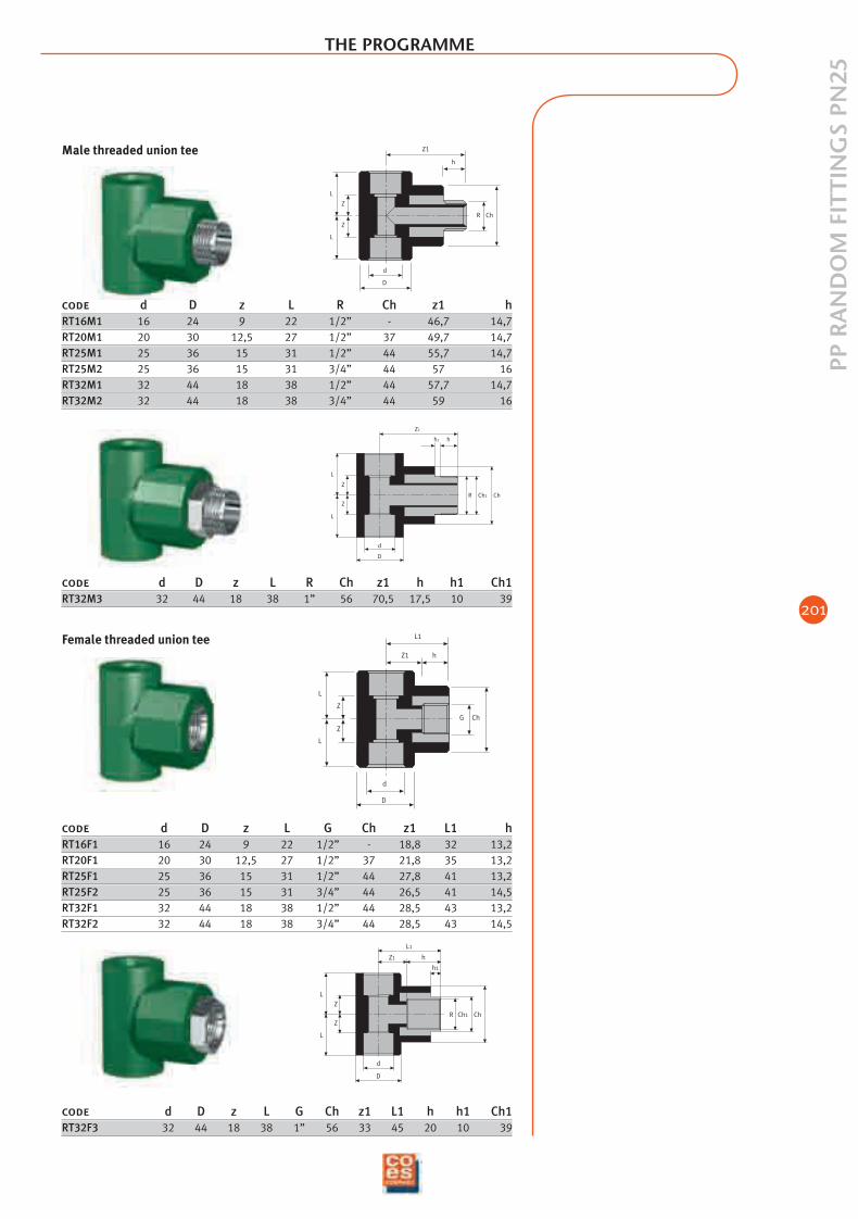
code d D z L R Ch z1 hRT16M1 16 24 9 22 1/2” - 46,7 14,7RT20M1 20 30 12,5 27 1/2” 37 49,7 14,7RT25M1 25 36 15 31 1/2” 44 55,7 14,7RT25M2 25 36 15 31 3/4” 44 57 16RT32M1 32 44 18 38 1/2” 44 57,7 14,7RT32M2 32 44 18 38 3/4” 44 59 16
Male threaded union tee
ChCh1R
hh1
Z1
L
L
Z
Z
D
d
G Ch
d
D
L1
Z1 h
L
L
Z
Z
code d D z L G Ch z1 L1 hRT16F1 16 24 9 22 1/2” - 18,8 32 13,2RT20F1 20 30 12,5 27 1/2” 37 21,8 35 13,2RT25F1 25 36 15 31 1/2” 44 27,8 41 13,2RT25F2 25 36 15 31 3/4” 44 26,5 41 14,5RT32F1 32 44 18 38 1/2” 44 28,5 43 13,2RT32F2 32 44 18 38 3/4” 44 28,5 43 14,5
ChCh1R
hZ1
L1
L
L
Z
Z
D
d
h1
code d D z L G Ch z1 L1 h h1 Ch1RT32F3 32 44 18 38 1” 56 33 45 20 10 39
Female threaded union tee
code d D z L R Ch z1 h h1 Ch1RT32M3 32 44 18 38 1” 56 70,5 17,5 10 39
02_ing_adduzione_e_riscald 9-02-2006 13:26 Pagina 201
202
PP R
AN
DO
M F
ITTI
NG
S PN
25THE PROGRAMME
L
z
d
D
ChR
Z1
h
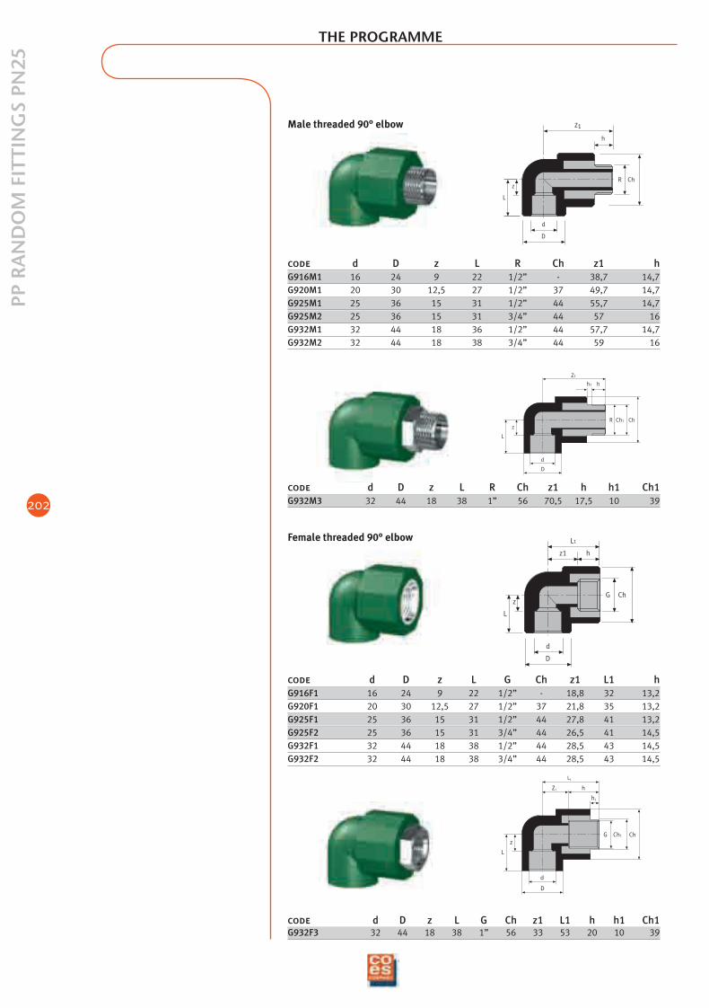
code d D z L R Ch z1 hG916M1 16 24 9 22 1/2” - 38,7 14,7G920M1 20 30 12,5 27 1/2” 37 49,7 14,7G925M1 25 36 15 31 1/2” 44 55,7 14,7G925M2 25 36 15 31 3/4” 44 57 16G932M1 32 44 18 36 1/2” 44 57,7 14,7G932M2 32 44 18 38 3/4” 44 59 16
Male threaded 90° elbow
z
L
d
D
ChCh1R
Z1
hh1
code d D z L R Ch z1 h h1 Ch1G932M3 32 44 18 38 1” 56 70,5 17,5 10 39
z
L
d
D
ChG
L1
z1 h
code d D z L G Ch z1 L1 hG916F1 16 24 9 22 1/2” - 18,8 32 13,2G920F1 20 30 12,5 27 1/2” 37 21,8 35 13,2G925F1 25 36 15 31 1/2” 44 27,8 41 13,2G925F2 25 36 15 31 3/4” 44 26,5 41 14,5G932F1 32 44 18 38 1/2” 44 28,5 43 14,5G932F2 32 44 18 38 3/4” 44 28,5 43 14,5
Female threaded 90° elbow
z
L
d
D
ChCh1G
Z1 h
h1
L1
code d D z L G Ch z1 L1 h h1 Ch1G932F3 32 44 18 38 1” 56 33 53 20 10 39
02_ing_adduzione_e_riscald 9-02-2006 13:26 Pagina 202
203
PP R
AN
DO
M F
ITTI
NG
S PN
25
THE PROGRAMME
L
z
d
D
ChR
z1
h
z
L
d
D
ChG
L1
z1 h
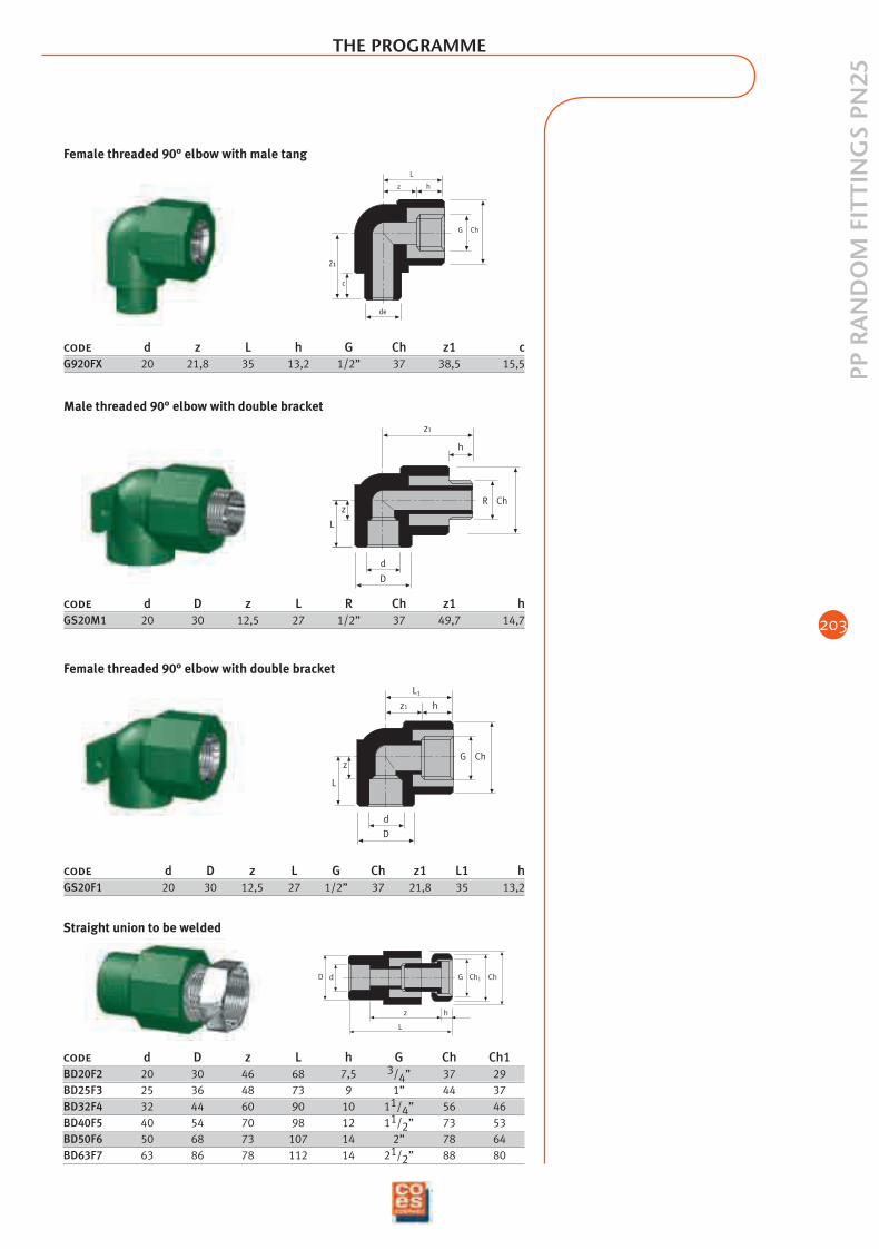
code d D z L R Ch z1 hGS20M1 20 30 12,5 27 1/2” 37 49,7 14,7
code d D z L G Ch z1 L1 hGS20F1 20 30 12,5 27 1/2” 37 21,8 35 13,2
Z1
c
de
L
z h
ChG
code d z L h G Ch z1 cG920FX 20 21,8 35 13,2 1/2” 37 38,5 15,5
Female threaded 90° elbow with male tang
Male threaded 90° elbow with double bracket
Female threaded 90° elbow with double bracket
dD
L
z h
G Ch1 Ch
code d D z L h G Ch Ch1BD20F2 20 30 46 68 7,5 3/4” 37 29BD25F3 25 36 48 73 9 1” 44 37BD32F4 32 44 60 90 10 11/4” 56 46BD40F5 40 54 70 98 12 11/2” 73 53BD50F6 50 68 73 107 14 2” 78 64BD63F7 63 86 78 112 14 21/2” 88 80
Straight union to be welded
02_ing_adduzione_e_riscald 9-02-2006 13:26 Pagina 203
204
PP R
AN
DO
M F
ITTI
NG
S PN
25
Ch
L
D G Ch1
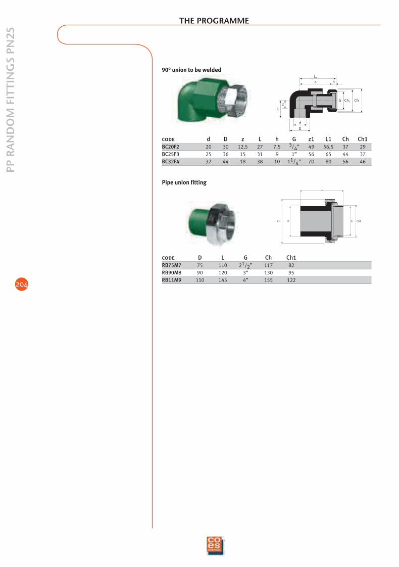
code D L G Ch Ch1RB75M7 75 110 21/2” 117 82RB90M8 90 120 3” 130 95RB11M9 110 145 4” 155 122
Pipe union fitting
Lz
D
d
G Ch1 Ch
z1
L1
h
code d D z L h G z1 L1 Ch Ch1BC20F2 20 30 12,5 27 7,5 3/4” 49 56,5 37 29BC25F3 25 36 15 31 9 1” 56 65 44 37BC32F4 32 44 18 38 10 11/4” 70 80 56 46
90° union to be welded
THE PROGRAMME
02_ing_adduzione_e_riscald 9-02-2006 13:26 Pagina 204
205
TAPS
AN
D S
HU
T-O
FF V
ALV
ES
THE PROGRAMME
L L
z z
L1
D d
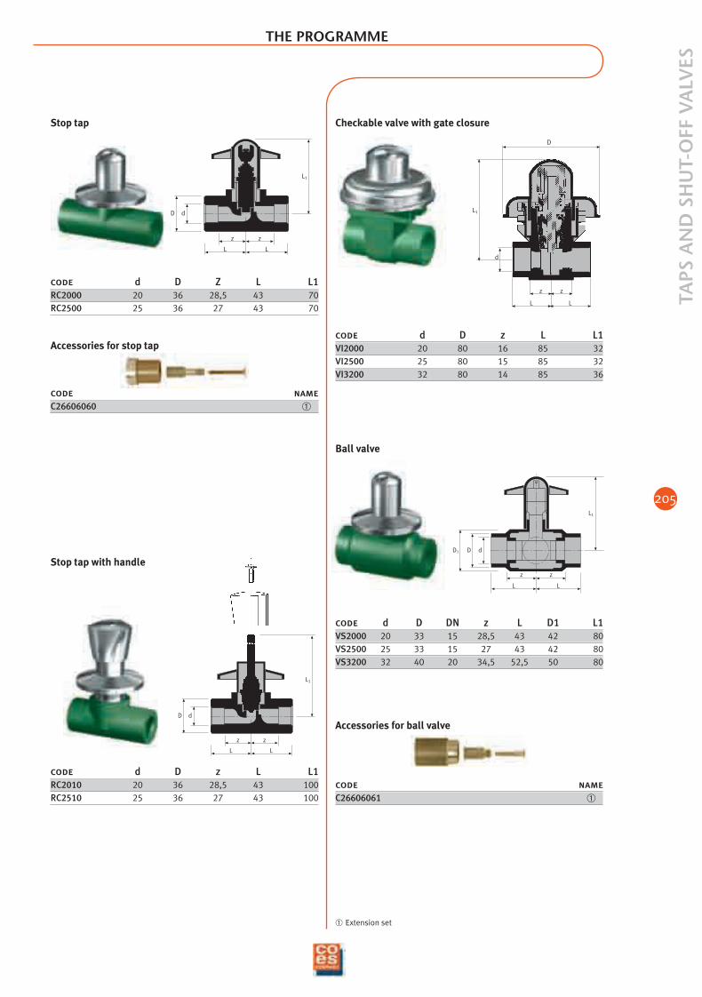
Stop tap
L L
z z
L1
D d
Stop tap with handle
L
D
z
d
L1
L
z
code d D z L L1VI2000 20 80 16 85 32VI2500 25 80 15 85 32VI3200 32 80 14 85 36
Checkable valve with gate closure
D1 D d
L1
z z
L L
Ball valve
code d D Z L L1RC2000 20 36 28,5 43 70RC2500 25 36 27 43 70
Accessories for stop tap
code nameC26606060 ➀
code d D z L L1RC2010 20 36 28,5 43 100RC2510 25 36 27 43 100
code d D DN z L D1 L1VS2000 20 33 15 28,5 43 42 80VS2500 25 33 15 27 43 42 80VS3200 32 40 20 34,5 52,5 50 80
Accessories for ball valve
code nameC26606061 ➀
➀ Extension set
02_ing_adduzione_e_riscald 9-02-2006 13:26 Pagina 205
206
AC
CES
SOR
IES
THE PROGRAMME
DKdi
f
S
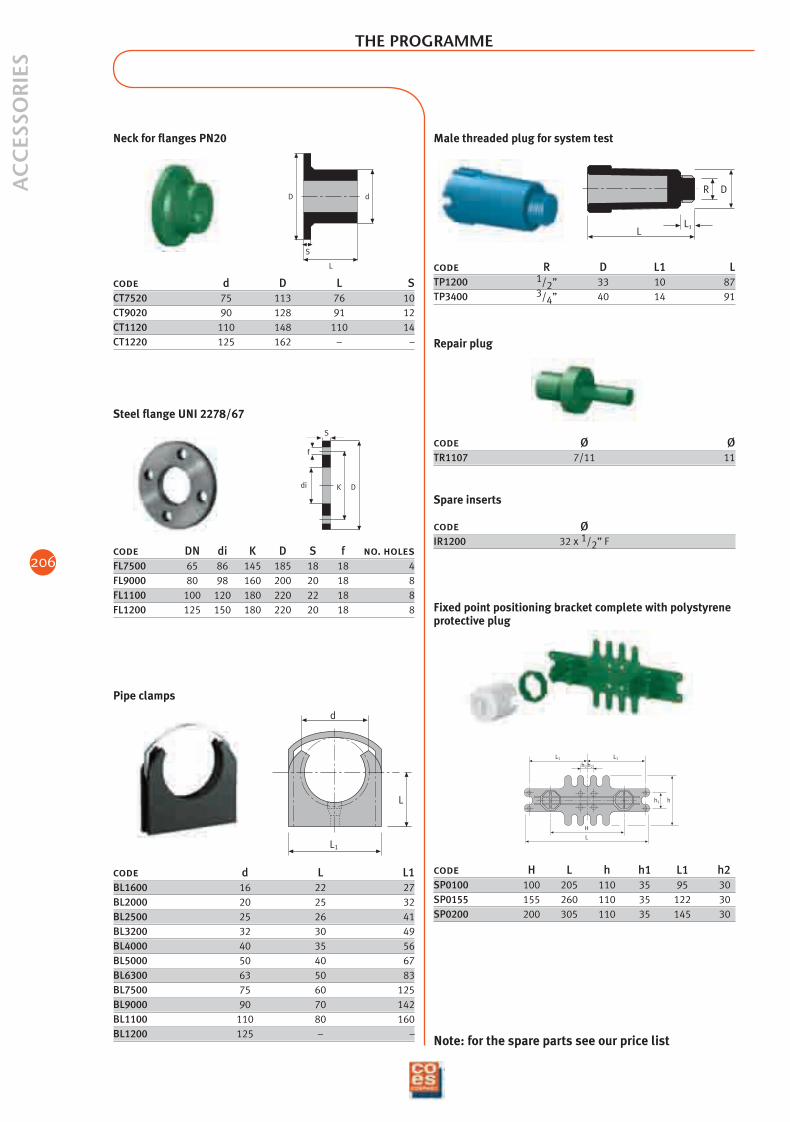
code DN di K D S f no. holesFL7500 65 86 145 185 18 18 4FL9000 80 98 160 200 20 18 8FL1100 100 120 180 220 22 18 8FL1200 125 150 180 220 20 18 8
Steel flange UNI 2278/67
d
L
L1
code d L L1BL1600 16 22 27BL2000 20 25 32BL2500 25 26 41BL3200 32 30 49BL4000 40 35 56BL5000 50 40 67BL6300 63 50 83BL7500 75 60 125BL9000 90 70 142BL1100 110 80 160BL1200 125 – –
Pipe clamps
LL1
DR
code R D L1 LTP1200 1/2” 33 10 87TP3400 3/4” 40 14 91
Male threaded plug for system test
code Ø ØTR1107 7/11 11
Spare inserts
code ØIR1200 32 x 1/2” F
Repair plug
L
H
L1 L1
h2 h2
h1 h
code H L h h1 L1 h2SP0100 100 205 110 35 95 30SP0155 155 260 110 35 122 30SP0200 200 305 110 35 145 30
Fixed point positioning bracket complete with polystyreneprotective plug
S
L
dD
code d D L SCT7520 75 113 76 10CT9020 90 128 91 12CT1120 110 148 110 14CT1220 125 162 – –
Neck for flanges PN20
Note: for the spare parts see our price list
02_ing_adduzione_e_riscald 9-02-2006 13:27 Pagina 206

207
02_ing_adduzione_e_riscald 9-02-2006 13:27 Pagina 207


![PnC TECH BUSAN[1] · 2017. 4. 11. · DVS 2207-11 Welding of thermoplastics – heated tool welding of pipes, piping parts and panels made of PP DVS 2210-1 Industrial Pipelines made](https://img.pdfslide.net/doc/110x75/60c806bfba444f40b5261c94/pnc-tech-busan1-2017-4-11-dvs-2207-11-welding-of-thermoplastics-a-heated.jpg)