Embed Size (px)
Citation preview


Important Notice***** MUST READ *****
Page 2 of 4Do not install a non-certified CGR-30P (CGR) in a certified aircraft. A certified CGR lists the appli-cable TSO numbers at the bottom of the Model Label.Before starting the installation make sure the unit will fit in the location you intend to install it withoutobstructing the operation of any controls.
If the CGR is configured to monitor the aircrafts fuel tanks, the CGR must be calibrated to the aircraftfuel system and the CGR's accuracy must be verified before flying the aircraft.
The accuracy and proper operation of each function displayed on the CGR should be verified beforethe aircraft is released for flight.
When the installation is finished, inspect the system for loose fittings, connections, clamps, probes andinspect for leaks, chafing, obstructions, heat damage and anything that may cause unsafe flight beforethe 1st run-up, after the 1st run-up and after the first flight.
Before allowing the aircraft to be flown, verify the instrument markings displayed on the CGR screensare accurate with the aircraft’s POH for every function displayed on the CGR.
Before allowing anyone to operate the aircraft they must read the Operating Manual including theImportant Notice there in. Keep the Operating Instructions in the aircraft at all times.
The use of the CGR requires recurring training for any pilot who will be flying the aircraft in which itis installed. Recurring training should include reading the CGR Installation Manual and OperationsManual and seeking a flight instructor for proper interpretation of information being displayed to thepilot.

Important Notice***** MUST READ *****
Page 3 of 4Fuel Level Accuracy Limitations:
The accuracy limitations of the CGR are listed below. It is the pilot/owner’s obligation to makeIt is the pilot/owner’s obligation to makeIt is the pilot/owner’s obligation to makeIt is the pilot/owner’s obligation to makeIt is the pilot/owner’s obligation to makeanyone flying the aircraft aware of these limitations.anyone flying the aircraft aware of these limitations.anyone flying the aircraft aware of these limitations.anyone flying the aircraft aware of these limitations.anyone flying the aircraft aware of these limitations.
1. Angle of Attack -1. Angle of Attack -1. Angle of Attack -1. Angle of Attack -1. Angle of Attack - The CGR must be calibrated with the aircraft in a cruise angle of attack. Ifthe aircraft is in an angle of attack other than cruise, the CGR may display inaccurate fuel levels(depending on the mounting location and type of sensor used). If your aircraft does not sit at a cruiseangle of attack when on the ground, it may not display accurate fuel levels. Test your aircraft atTest your aircraft atTest your aircraft atTest your aircraft atTest your aircraft atdifferent angles of attack to see the affects on the CGR fuel level readings.different angles of attack to see the affects on the CGR fuel level readings.different angles of attack to see the affects on the CGR fuel level readings.different angles of attack to see the affects on the CGR fuel level readings.different angles of attack to see the affects on the CGR fuel level readings.
2. Full Fuel Readings -Full Fuel Readings -Full Fuel Readings -Full Fuel Readings -Full Fuel Readings - As a tank is filled the fuel sensor may not be able to detect the fuel enter-ing the upper corners of the fuel tank. If this is the case with your sensor, the CGR will display lowerfuel levels than the actual fuel in the tanks when the tanks are full. When the fuel level drops to apoint where the fuel sensor starts to detect a change, the displayed fuel level should be accurate.Check the accuracy of your system by comparing the displayed fuel levels on the CGRCheck the accuracy of your system by comparing the displayed fuel levels on the CGRCheck the accuracy of your system by comparing the displayed fuel levels on the CGRCheck the accuracy of your system by comparing the displayed fuel levels on the CGRCheck the accuracy of your system by comparing the displayed fuel levels on the CGRto the fuel levels listed in the flight manual at each fill up.to the fuel levels listed in the flight manual at each fill up.to the fuel levels listed in the flight manual at each fill up.to the fuel levels listed in the flight manual at each fill up.to the fuel levels listed in the flight manual at each fill up.
3. Low Fuel Readings - 3. Low Fuel Readings - 3. Low Fuel Readings - 3. Low Fuel Readings - 3. Low Fuel Readings - Do not rely on the CGR to determine the fuel level in the tankDo not rely on the CGR to determine the fuel level in the tankDo not rely on the CGR to determine the fuel level in the tankDo not rely on the CGR to determine the fuel level in the tankDo not rely on the CGR to determine the fuel level in the tankfor an indicated tank level below 1/8for an indicated tank level below 1/8for an indicated tank level below 1/8for an indicated tank level below 1/8for an indicated tank level below 1/8. . . . . You should always fly the aircraft in such a manner as tomaintain at least the FAA minimum fuel requirements in the aircraft at all times.
4. Improper Calibration -4. Improper Calibration -4. Improper Calibration -4. Improper Calibration -4. Improper Calibration - If the CGR has not been properly calibrated it will not display accuratefuel levels in the tanks. It is important you verify the accuracy of the CGR. Always crosscheckAlways crosscheckAlways crosscheckAlways crosscheckAlways crosscheckyour measured fuel levels in the tanks with the readings on the CGR before each flight.your measured fuel levels in the tanks with the readings on the CGR before each flight.your measured fuel levels in the tanks with the readings on the CGR before each flight.your measured fuel levels in the tanks with the readings on the CGR before each flight.your measured fuel levels in the tanks with the readings on the CGR before each flight.
5. Poor Connections -5. Poor Connections -5. Poor Connections -5. Poor Connections -5. Poor Connections - Poor connections between the wires leading from the EDC to the fuelsensors can become intermittent. An intermittent connection most likely will show up as wandering orinaccurate readings on the CGR. Always crosscheck your measured fuel levels in the tanksAlways crosscheck your measured fuel levels in the tanksAlways crosscheck your measured fuel levels in the tanksAlways crosscheck your measured fuel levels in the tanksAlways crosscheck your measured fuel levels in the tankswith the readings on the CGR before each flight.with the readings on the CGR before each flight.with the readings on the CGR before each flight.with the readings on the CGR before each flight.with the readings on the CGR before each flight.
6. Defective Fuel Level Sensors -6. Defective Fuel Level Sensors -6. Defective Fuel Level Sensors -6. Defective Fuel Level Sensors -6. Defective Fuel Level Sensors - Fuel sensors can become intermittent or change resistancewith age. It is not uncommon to find intermittent problems even in new sensors. An intermittentproblem with a fuel sensor most likely will show up as wandering or inaccurate readings on the CGR.Always crosscheck the measured fuel levels in the tanks with the readings on the CGR atAlways crosscheck the measured fuel levels in the tanks with the readings on the CGR atAlways crosscheck the measured fuel levels in the tanks with the readings on the CGR atAlways crosscheck the measured fuel levels in the tanks with the readings on the CGR atAlways crosscheck the measured fuel levels in the tanks with the readings on the CGR ateach fill up.each fill up.each fill up.each fill up.each fill up.
If you ever find an inaccuracy issue or any other problem with a fuel level display onIf you ever find an inaccuracy issue or any other problem with a fuel level display onIf you ever find an inaccuracy issue or any other problem with a fuel level display onIf you ever find an inaccuracy issue or any other problem with a fuel level display onIf you ever find an inaccuracy issue or any other problem with a fuel level display onthe CGR, troubleshoot and fix the problem before flying the aircraft.the CGR, troubleshoot and fix the problem before flying the aircraft.the CGR, troubleshoot and fix the problem before flying the aircraft.the CGR, troubleshoot and fix the problem before flying the aircraft.the CGR, troubleshoot and fix the problem before flying the aircraft.
If you do not agree to all of the above, DO NOT INSTALL THIS PRODUCT.DO NOT INSTALL THIS PRODUCT.DO NOT INSTALL THIS PRODUCT.DO NOT INSTALL THIS PRODUCT.DO NOT INSTALL THIS PRODUCT. This product maybe returned for a refund. Contact Electronics International Inc. for details.

Important Fuel Level Considerations:
DO NOT RELY SOLELY ON THE FUEL LEVEL DISPLAYED ON THE CGR TODETERMINE THE FUEL LEVELS IN THE AIRCRAFT. The use of the CGR does noteliminate or reduce the necessity for the pilot to use good flight planning, preflight and in-flighttechniques for managing fuel. It is important the pilot adopt the practices listed below. If you arenot familiar with these techniques, contact the FAA to acquire proper training.
1. A copy of the Operating Manual must be in the aircraft at all times.
2. Flight Planning - Always calculate the fuel requirement for each leg of a flight, including anyalternate plans for bad weather. Keep this information available in the aircraft during theflight. Keep a chart of the published fuel flows for various flight/engine conditions in theaircraft. Keep a chart of the measured fuel flows for various flights in the aircraft. Measuredfuel flows can be considerably different from published figures. This usually is due to old,inaccurate engine instruments.
3. Preflight - Do not rely on the CGR to determine the fuel level in the fuel tanks. Thepilot must visually check/measure the fuel levels in the tanks before every takeoff.Crosscheck the measured fuel levels with the displayed levels on the CGR. Also, crosscheckthese levels with the fuel requirements for the flight listed in your flight plan.
4. In Flight - Make the CGR part of your normal instrument scan. Crosscheck the fuel levelsdisplayed on the CGR with your flight plan at each leg of the flight or every 30 minutes(whichever happens first). If there is a discrepancy, land the aircraft at the nearest airport andverify the fuel levels. Discrepancies should be taken seriously.
5. New Pilot or Owner of the Aircraft - If there is a new pilot or owner of the aircraft, it isthe previous aircraft pilot/owner’s responsibility to insure the new pilot has read thismanual and is aware of any accuracy limitations and other important considerations.All limitations and operating characteristics learned from operating the CGR must bepassed on to the new pilot/owner.
If you do not agree or are unwilling to comply with the information/requirements contained within thisImportant Notice, DO NOT INSTALL THIS PRODUCT.DO NOT INSTALL THIS PRODUCT.DO NOT INSTALL THIS PRODUCT.DO NOT INSTALL THIS PRODUCT.DO NOT INSTALL THIS PRODUCT. This product may be returned for arefund. Contact Electronics International Inc. for details.
Important Notice***** MUST READ *****
Page 4 of 4

Contents(Page 1 of 3)
Warranty/Agreement-------------------------------------------------------------------------------------- 1A
1.0 System Description ----------------------------------------------------------------------------------- 41.1 System Description --------------------------------------------------------------------------- 4
1.1.1 CGR Display ---------------------------------------------------------------------------- 41.1.2 EDC-33P --------------------------------------------------------------------------------- 41.1.3 Probes, Transducers and Modules --------------------------------------------------- 41.1.4 Wiring & Extension Cables ----------------------------------------------------------- 4
1.2 Operational Overview ------------------------------------------------------------------------------- 5
1.3 Installation Overview --------------------------------------------------------------------------------- 5
2.0 Hardware Installation -------------------------------------------------------------------------------- 62.1 Important Information and Initial Check Out: ------------------------------------------- 82.2 Review the "EDC Wiring Work Sheets:" ------------------------------------------------- 92.3 Verify you have all the necessary Probes, Modules, Transducers and Cables: ----- 92.4 Install the CGR Display: --------------------------------------------------------------------- 92.5 Install the Temperature Probes: ------------------------------------------------------------- 102.6 Install the Pressure Transducers: ----------------------------------------------------------- 122.7 Install the CO Detector, G-Sensor and/or Other Available CGR Options ------- 152.8 Install the Shunt: ------------------------------------------------------------------------------ 152.9 Install the Fuel Flow Transducer: -------------------------------------------------------- 172.10 Install the P-300C Fuel Level Probes (OEM or Experimental) --------------------- 242.11 Install the P-300M Fuel Levl Sender: ---------------------------------------------------- 242.12 Install the Resistive Fuel Level Module (RFLM-4-X): ------------------------------- 252.13 Install the Voice Alarm Control Panel (OEM Only): -------------------------------- 252.14 Install the Intensity Control Pot CP-1A (optional): ----------------------------------- 262.15 Install the Master Warning (red) and Caution (yellow) Lights: ----------------------- 262.16 Install the Interface Circuit for a PWM Backlight System (Optional): -------------- 262.17 Install the USB-6A (Optional): ------------------------------------------------------------ 272.18 Install the FM-SC or AC-1 Converter (Optional): -------------------------------------- 272.19 Install any Additional Modules (Optional): ---------------------------------------------- 272.20 Install the EDC-33P: ------------------------------------------------------------------------ 27
3.0 Install the EDC Wire Harnesses and Route Wires ---------------------------------------------- 283.1 Attach the three EDC 37-pin wire harnesses to the EDC: ---------------------------- 303.2 Connect the EDC Harness to the Temperature Probes: -------------------------------- 303.3 Connect the EDC Harness to the Pressure Transdcueres: ----------------------------- 303.4 Connect the EDC Harness to the Shunt: -------------------------------------------------- 313.5 Connect the EDC Harness to the Fuel Flow Transducer: ----------------------------- 313.6 Connect the EDC Harness to the Existing Capacitive Fuel Level System: -------- 313.7 Connect the RFLM-4-x Harness to the EDC Connector and to the Resistive Fuel Level Sensors: ------------------------------------------------------------------------------- 323.8 Connect the EDC Harness to the EI P-300C Capacitive Fuel Level Probes: ----- 32

3.9 Connect the EDC Harness to the P-300M Magnetic Fuel Level Senders: ---------- 333.10 Connect the EDC Harness (Volts Meassurement Pin) to the Bus: ----------------- 333.11 Connect the EDC Harness to the RPM Signals: ---------------------------------------- 333.12 Setup the EDC for a 4 or 6-Cylinder Engine: ------------------------------------------- 333.13 Connect the EDC Harness to Power and Ground: ------------------------------------ 343.14 Route the EDC 5V-Serial Wire to the CGR Connector: ------------------------------ 34
4.0 Install the CGR Wire Harness and Route the Wires ------------------------------------------- 364.1 Attach the CGR 25-pin D-sub Connector to the CGR: -------------------------------- 384.2 Connect the EDC 5V-Serial Output Wire to the CGR 5V-Serial Input Wire: ----- 384.3 Connect the CGR Harness to the Master Warning and Caution Lights: ------------- 384.4 Connect the CGR Harness to the Voice Alarm Control Panel (OEM Only): ------ 384.5 Connect the CGR Harness to the Audio Panel (OEM Only): ------------------------ 394.6 Connect the CGR Harness to the Moving Map Data Out from the GPS: ---------- 394.7 Connect the CGR Harness to the Fuel Data Input on the GPS: ---------------------- 394.8 Connect the CGR Harness to Power and Ground: -------------------------------------- 394.9 Connect the CGR Harness to the CO-Guardian CO Detector: ---------------------- 40
5.0 Mandatory System Setup and Checkout --------------------------------------------------------- 425.1 Power-On Checkout -------------------------------------------------------------------------- 445.2 Perform all Steps Listed in the "CGR-30P Setup Checklist" ------------------------ 445.3 Ground Run Checkout ------------------------------------------------------------------------ 445.4 First Flight Checkout -------------------------------------------------------------------------- 455.5 Read the "Warranty/Agreement" and the "Important Notice" ----------------------- 45
6.0 Installation Data -------------------------------------------------------------------------------------- 466.1 Instructions for Continued Airworthiness (ICA): ----------------------------------------- 486.2 Airworthiness Limitations: -------------------------------------------------------------------- 486.3 Installing a D-sub Pin onto a TC or Tin Copper Wire: ---------------------------------- 48
CGR-30P Wiring Work Sheet -------------------------------------------------------------------- 50EDC Wiring Work Sheet Top Connector ------------------------------------------------------ 51EDC Wiring Work Sheet Middle Connector --------------------------------------------------- 52EDC Wiring Work Sheet Bottom Connector -------------------------------------------------- 53EDC Template -------------------------------------------------------------------------------------- 54
7.0 Troubleshooting --------------------------------------------------------------------------------------- 567.1 CGR or EDC Problem ------------------------------------------------------------------------ 587.2 Pressure Problem with one Function ------------------------------------------------------- 597.3 Temperature Problem on all Channels ----------------------------------------------------- 597.4 Temperature Problem with one Function ------------------------------------------------- 607.5 RPM Problem ----------------------------------------------------------------------------------- 607.6 Fuel Flow Problem ----------------------------------------------------------------------------- 617.7 Amp Problem ----------------------------------------------------------------------------------- 627.8 Resistive Fuel Level Problem ---------------------------------------------------------------- 627.9 Capacitive Fuel Level Problem -------------------------------------------------------------- 637.10 Voltage Problem ------------------------------------------------------------------------------ 64
Contents(Page 2 of 3)

8.0 Technical Data ---------------------------------------------------------------------------------------- 66Specifications, Functions and Features ---------------------------------------------------------- 68
Appendix ---------------------------------------------------------------------------------------------------- AA1.0 Appendix: LASAR Ignition RPM Filter -------------------------------------------------- A1.0A2.0 Appendix EDC-33P-8 for 7, 8, 9-Cylinder Engines and High RPM Engines ---- A2.0A3.0 Appendix Connecting an EDC RPM Channel to a Lightspeed Plasma II or
III Ignition --------------------------------------------------------------------------------------- A3.0A4.0 CGR-30P Twin Engine Installation Instructions --------------------------------------- A4.0
STC and AML --------------------------------------------------------------------------------------------- Last Pages
Contents(Page 3 of 3)


1A
Warranty / Agreement
Electronics International Inc. (EI) warrants this instrument and system components to be free from defects inmaterials and workmanship for a period of one year from the user invoice date. EI will repair or replace anyitem under the terms of this Warranty provided the item is returned to the factory prepaid.
1. If you do not agree to and accept If you do not agree to and accept If you do not agree to and accept If you do not agree to and accept If you do not agree to and accept ALLALLALLALLALL the terms of this Warranty/Agreement, the terms of this Warranty/Agreement, the terms of this Warranty/Agreement, the terms of this Warranty/Agreement, the terms of this Warranty/Agreement, DO NOT InstallDO NOT InstallDO NOT InstallDO NOT InstallDO NOT InstallThis ProductThis ProductThis ProductThis ProductThis Product. . . . . You may return the product for a refund, contact Electronics International Inc. for details.
2. Electronics International Inc. is not liable or responsible for a pilot’s action or any situation that results inpersonal injury, property damage, missed commitments, lack of use of an aircraft or any expenses incurred dueto: product failure, inaccuracy in displayed data or text files, display or display format issues, software bugs orproblems, upgrade or customization issues, misinterpretation of the display, warning and/or limit settings,calibration problems, installation issues (leaks, mis-wiring, obstructions, damage to aircraft or components,incorrect installation of any parts, wrong parts, part that don’t fit, etc.) or any other issues related to the installa-tion or operation of this product. All of the above are solely the pilot’s and/or installer’s responsibility. Thepilot mustmustmustmustmust understand the operation of this product before flying the aircraft. The pilot will not allow anyoneto operate the aircraft that does not know the operation of this product. The pilot will keep the instrument'sOperating Instructions in the aircraft at all times.
By installing this product, the aircraft owner/pilot and installer agree to hold Electronics International Inc.harmless and in no way responsible for monetary compensation, including punitive damages for any incident,harm and/or damage associated with this product (including but not limited to the ones listed above). If you donot agree to any part of this Warranty/Agreement, DO NOT INSTALL THIS PRODUCT.DO NOT INSTALL THIS PRODUCT.DO NOT INSTALL THIS PRODUCT.DO NOT INSTALL THIS PRODUCT.DO NOT INSTALL THIS PRODUCT.
3. This Warranty/Agreement shall not apply to any product that has been repaired or altered by any personother than Electronics International Inc., or that has been subjected to misuse, accident, incorrect wiring,negligence, improper or unprofessional assembly or improper installation by any person. This warrantyThis warrantyThis warrantyThis warrantyThis warrantydoes not cover any reimbursement for any person’s time for installation, removal, assembly ordoes not cover any reimbursement for any person’s time for installation, removal, assembly ordoes not cover any reimbursement for any person’s time for installation, removal, assembly ordoes not cover any reimbursement for any person’s time for installation, removal, assembly ordoes not cover any reimbursement for any person’s time for installation, removal, assembly orrepair.repair.repair.repair.repair. Electronics International retains the right to solely determine the reason or cause for warranty repair.
4. This warranty does not extend to any machine, vehicle, boat, aircraft or any other device to which theElectronics International Inc. product may be connected, attached, interconnected or used in conjunction within any way.
5. Personal injury or property damage due to misinterpretation or lack of understanding of this product issolely the pilots' responsibility. The pilot mustmustmustmustmust understand all aspects of the operation of this product beforeflying the aircraft. If he/she does not, he or she agrees to seek training from a knowledgeable instructor. Thepilot also agree that no one will be allowed to operate the aircraft that does not know the operation of thisproduct and will Keep the Operating Instructions in the aircraft at all times.Keep the Operating Instructions in the aircraft at all times.Keep the Operating Instructions in the aircraft at all times.Keep the Operating Instructions in the aircraft at all times.Keep the Operating Instructions in the aircraft at all times.
6. The obligation assumed by Electronics International Inc. under this warranty is limited to repair, replace-ment or refund of the product, at the sole discretion of Electronics International Inc.
7. Electronics International Inc. is not liable for expenses incurred by the customer or installer due to factoryupdates, modifications, improvements, changes, or any other alterations to the product that may affect theform, fit, function or operation of the product.
More On Back of this PageMore On Back of this PageMore On Back of this PageMore On Back of this PageMore On Back of this Page
8. Electronics International is not responsible for shipping charges or damages incurred under this Warranty.
9. No representative is authorized to assume any other liability for Electronics International Inc. in connectionwith the sale of Electronics International Inc. products.
10. You must read the entire Installation and Operating Instructions for this instrument. If youYou must read the entire Installation and Operating Instructions for this instrument. If youYou must read the entire Installation and Operating Instructions for this instrument. If youYou must read the entire Installation and Operating Instructions for this instrument. If youYou must read the entire Installation and Operating Instructions for this instrument. If youdo not agree to and accept the terms of this Warranty/Agreement and the responsibilities setdo not agree to and accept the terms of this Warranty/Agreement and the responsibilities setdo not agree to and accept the terms of this Warranty/Agreement and the responsibilities setdo not agree to and accept the terms of this Warranty/Agreement and the responsibilities setdo not agree to and accept the terms of this Warranty/Agreement and the responsibilities setforth in these manuals, DO NOT install this product, contact E.I. for a refund.forth in these manuals, DO NOT install this product, contact E.I. for a refund.forth in these manuals, DO NOT install this product, contact E.I. for a refund.forth in these manuals, DO NOT install this product, contact E.I. for a refund.forth in these manuals, DO NOT install this product, contact E.I. for a refund.
This Warranty is made only to the original user. THIS WARRANTY IS IN LIEU OF ALL OTHERTHIS WARRANTY IS IN LIEU OF ALL OTHERTHIS WARRANTY IS IN LIEU OF ALL OTHERTHIS WARRANTY IS IN LIEU OF ALL OTHERTHIS WARRANTY IS IN LIEU OF ALL OTHERWARRANTIES OR OBLIGATIONS: EXPRESS OR IMPLIED. MANUFACTURER EXPRESSLYWARRANTIES OR OBLIGATIONS: EXPRESS OR IMPLIED. MANUFACTURER EXPRESSLYWARRANTIES OR OBLIGATIONS: EXPRESS OR IMPLIED. MANUFACTURER EXPRESSLYWARRANTIES OR OBLIGATIONS: EXPRESS OR IMPLIED. MANUFACTURER EXPRESSLYWARRANTIES OR OBLIGATIONS: EXPRESS OR IMPLIED. MANUFACTURER EXPRESSLYDISCLAIMS ALL IMPLIED WARRANTIES OF MERCHANTABILITY OR FITNESS FOR ADISCLAIMS ALL IMPLIED WARRANTIES OF MERCHANTABILITY OR FITNESS FOR ADISCLAIMS ALL IMPLIED WARRANTIES OF MERCHANTABILITY OR FITNESS FOR ADISCLAIMS ALL IMPLIED WARRANTIES OF MERCHANTABILITY OR FITNESS FOR ADISCLAIMS ALL IMPLIED WARRANTIES OF MERCHANTABILITY OR FITNESS FOR APARTICULAR PURPOSE. PURCHASER AGREES THAT IN NO EVENT SHALL MANUFAC-PARTICULAR PURPOSE. PURCHASER AGREES THAT IN NO EVENT SHALL MANUFAC-PARTICULAR PURPOSE. PURCHASER AGREES THAT IN NO EVENT SHALL MANUFAC-PARTICULAR PURPOSE. PURCHASER AGREES THAT IN NO EVENT SHALL MANUFAC-PARTICULAR PURPOSE. PURCHASER AGREES THAT IN NO EVENT SHALL MANUFAC-TURER BE LIABLE FOR SPECIAL, INCIDENTAL OR CONSEQUENTIAL DAMAGES, IN-TURER BE LIABLE FOR SPECIAL, INCIDENTAL OR CONSEQUENTIAL DAMAGES, IN-TURER BE LIABLE FOR SPECIAL, INCIDENTAL OR CONSEQUENTIAL DAMAGES, IN-TURER BE LIABLE FOR SPECIAL, INCIDENTAL OR CONSEQUENTIAL DAMAGES, IN-TURER BE LIABLE FOR SPECIAL, INCIDENTAL OR CONSEQUENTIAL DAMAGES, IN-CLUDING LOST PROFITS OR LOSS OF USE OR OTHER ECONOMIC LOSS. EXCEPT ASCLUDING LOST PROFITS OR LOSS OF USE OR OTHER ECONOMIC LOSS. EXCEPT ASCLUDING LOST PROFITS OR LOSS OF USE OR OTHER ECONOMIC LOSS. EXCEPT ASCLUDING LOST PROFITS OR LOSS OF USE OR OTHER ECONOMIC LOSS. EXCEPT ASCLUDING LOST PROFITS OR LOSS OF USE OR OTHER ECONOMIC LOSS. EXCEPT ASEXPRESSLY PROVIDED HEREIN, MANUFACTURER DISCLAIMS ALL OTHER LIABILITYEXPRESSLY PROVIDED HEREIN, MANUFACTURER DISCLAIMS ALL OTHER LIABILITYEXPRESSLY PROVIDED HEREIN, MANUFACTURER DISCLAIMS ALL OTHER LIABILITYEXPRESSLY PROVIDED HEREIN, MANUFACTURER DISCLAIMS ALL OTHER LIABILITYEXPRESSLY PROVIDED HEREIN, MANUFACTURER DISCLAIMS ALL OTHER LIABILITYTO PURCHASER OR ANY OTHER PERSON IN CONNECTION WITH THE USE OR PERFOR-TO PURCHASER OR ANY OTHER PERSON IN CONNECTION WITH THE USE OR PERFOR-TO PURCHASER OR ANY OTHER PERSON IN CONNECTION WITH THE USE OR PERFOR-TO PURCHASER OR ANY OTHER PERSON IN CONNECTION WITH THE USE OR PERFOR-TO PURCHASER OR ANY OTHER PERSON IN CONNECTION WITH THE USE OR PERFOR-MANCE OF MANUFACTURER’S PRODUCTS, INCLUDING SPECIFICALLY LIABILITY INMANCE OF MANUFACTURER’S PRODUCTS, INCLUDING SPECIFICALLY LIABILITY INMANCE OF MANUFACTURER’S PRODUCTS, INCLUDING SPECIFICALLY LIABILITY INMANCE OF MANUFACTURER’S PRODUCTS, INCLUDING SPECIFICALLY LIABILITY INMANCE OF MANUFACTURER’S PRODUCTS, INCLUDING SPECIFICALLY LIABILITY INTORT.TORT.TORT.TORT.TORT.
1B

2
1.01.01.01.01.0System OverviewSystem OverviewSystem OverviewSystem OverviewSystem Overview
1.1 System Description
1.1.1 CGR Display:1.1.1 CGR Display:1.1.1 CGR Display:1.1.1 CGR Display:1.1.1 CGR Display:
1.1.2 EDC-33P:1.1.2 EDC-33P:1.1.2 EDC-33P:1.1.2 EDC-33P:1.1.2 EDC-33P:
1.1.3 Probes, Transducers and Modules:1.1.3 Probes, Transducers and Modules:1.1.3 Probes, Transducers and Modules:1.1.3 Probes, Transducers and Modules:1.1.3 Probes, Transducers and Modules:
1.1.4 Wiring & Extension Cables:1.1.4 Wiring & Extension Cables:1.1.4 Wiring & Extension Cables:1.1.4 Wiring & Extension Cables:1.1.4 Wiring & Extension Cables:
1.2 Operational Overview:
1.3 Installation Overview:

1.1 System Description:
The CGR-30P Glass Panel Engine Monitor installation consists of four major components: the CGR Display,the Engine Data Converter (EDC-33P), the Probes, Transducers & Modules, and the Wiring and ExtensionCables.
4
1.1.1 1.1.1 1.1.1 1.1.1 1.1.1 CGR Display:CGR Display:CGR Display:CGR Display:CGR Display:
The CGR-30P (CGR) display measures 3.25" wide by 3.25" high by 4.36" deep and is designed to bemounted from behind the aircraft instrument panel.
The 25-pin D-sub connector on the back of the CGR display is used to interface the CGR to the EDC-33P, Power & Ground, GPS, Master Warning and Caution Lights and Audio Panel (experimental only).
1.1.2 1.1.2 1.1.2 1.1.2 1.1.2 EDC-33P:EDC-33P:EDC-33P:EDC-33P:EDC-33P:
The EDC-33P (Engine Data Converter, "EDC") converts all of the engine and aircraft system signalsinto serial data. This data is transmitted to the CGR display via one wire 5V-Serial Bus. Up to twoEDC’s can be connected to the CGR display. The EDC measures 4.5" long by 3.5" wide by 2.2" highand is to be mounted on cockpit side of the firewall or in an equipment bay. The EDC reduces the wirebundle to the instrument panel by over 100 wires. There are three 37-pin D-sub connectors that inter-face the EDC to the various probes, transducers and modules.
1.1.3 1.1.3 1.1.3 1.1.3 1.1.3 Probes, Transducers and Modules:Probes, Transducers and Modules:Probes, Transducers and Modules:Probes, Transducers and Modules:Probes, Transducers and Modules:
The various probes, transducers and modules are mounted in the aircraft at appropriate locations.
1.1.4 1.1.4 1.1.4 1.1.4 1.1.4 Wiring & Extension Cables:Wiring & Extension Cables:Wiring & Extension Cables:Wiring & Extension Cables:Wiring & Extension Cables:
The extension cables and wiring provide the connections from the probes, modules or direct connec-tions to the EDC inputs. Once the Wiring and Extension Cables are installed into the aircraft theybecome semi-permanent. Everything else (CGR, EDC, Probes and Modules) can be easily disconnectedand removed.

1.2 Operational Overview:
The CGR system measures a primary engine or aircraft function using a probe or transducer and displays thatfunction on the CGR screen using the following steps:
A. A probe is mechanically connected to the aircraft and electrically connected to an EDC input. Thepre-wired harness provides most of the electrical connections from the probes to the EDC inputs.
B. The EDC converts the signals from the probes to a digital format and sends the data to the CGRthrough the serial bus. The EDC has 33 inputs. Many of these inputs can be used to monitor varioustypes of functions.
C. The CGR receives the data from the EDC and the data is processed through the CGR as follows:
1. A Function is created in the CGR and is linked to an EDC input.
2. The function is assigned a screen location onto the Main or System Screen of the CGR.
3. Calibration, units, redlines, limits etc. are assigned to the data coming into that function.
Much of the setup for the certified CGR is done at the factory and cannot be changed by the pilot or installer.See the following Password Protection Section for more information.
1.3 Installation Overview:
The installer may want to use the “CGR-30P Installation Checklist” to install this system. The Checklist is a sepa-rate document provided with the CGR-30P system. The installer should start the installation by reviewing the CGRand EDC Wiring Work Sheets. There are four work sheets, one for each of the 37-pin D-Sub connectors on theEDC and one for the CGR. The work sheets are packaged with each of the three EDC wire harnesses and one forthe CGR. The work sheets provide a list of the functions and probes/transducers included with this kit. For a twinengine installation refer to appendix A8.0. The installation is achieved by performing the following steps:
A. The CGR display is installed. The CGR is mounted from behind the instrument panel in a standard3 1/8" hole.
B. Probes and Transducers are installed.
C. Control Panels, Pots and Warning Lights are installed.
D. The EDC is installed. The EDC should be installed on the inside of the cockpit or in an instrumentbay with the connectors pointing down. For a twin-engine aircraft it can be installed on the backside(not the engine side) of the firewall with the connectors pointing down.
E. The Wire Harnesses are installed. The wire harnesses for the EDC and CGR are pre-wired and in-cluded in the kit.
F. Field Calibration/Setup steps are performed. If Fuel Tanks are to be monitored, the MVP-50 must becalibrated to the tank sendors.
G. System Checkout is performed.
5

6
2.02.02.02.02.0Hardware InstallationHardware InstallationHardware InstallationHardware InstallationHardware Installation
2.1 Important Information and Initial Checkout:
2.2 Review the "EDC Wiring Work Sheets:"
2.3 Verify You Have all the Probes, Modules, Transducers and Cables:
2.4 Install the CGR Display:
2.5 Install the Temperature Probes:
2.6 Install the Pressure Transducers:
2.7 Install the CO Detector, G-Sensor and/or Other Available CGR Options:
2.8 Install the Shunt (for Amps):
2.9 Install the Fuel Flow Transducer:
2.10 Install the EI P-300C Fuel Level Probes (OEM or Experimental Only):
2.11 Install the EI P-300M Fuel Level Sender:
2.12 Install the Resistive Fuel Level Module (RFLM-4-X):
2.13 Install the Voice Alarm Control Panel (OEM Only):
2.14 Install the Intensity Control Pot CP-1A (Optional):
2.15 Install the Master Warning (red) and Caution (yellow) Lights:
2.16 Install the Interface Circuit for a PWM Backlight System (Optional):
2.17 Install the USB-6A (Optional):
2.18 Install the FM-SC or AC-1 Converter (Optional):
2.19 Install any Additional Modules (Optional):
2.20 Installing the EDC-33P:

2.1 Important Information and Initial Checkout:
A. The installer and aircraft owner must read the Warranty/Agreement before starting theThe installer and aircraft owner must read the Warranty/Agreement before starting theThe installer and aircraft owner must read the Warranty/Agreement before starting theThe installer and aircraft owner must read the Warranty/Agreement before starting theThe installer and aircraft owner must read the Warranty/Agreement before starting theinstallation.installation.installation.installation.installation. There is information in the Warranty/Agreement that may alter your decision to installthis instrument. If you do not accept the terms of the Warranty/Agreement, do not installIf you do not accept the terms of the Warranty/Agreement, do not installIf you do not accept the terms of the Warranty/Agreement, do not installIf you do not accept the terms of the Warranty/Agreement, do not installIf you do not accept the terms of the Warranty/Agreement, do not installthis instrument.this instrument.this instrument.this instrument.this instrument.
B. If you are not an FAA Certified Aircraft Mechanic familiar with the issues of installing If you are not an FAA Certified Aircraft Mechanic familiar with the issues of installing If you are not an FAA Certified Aircraft Mechanic familiar with the issues of installing If you are not an FAA Certified Aircraft Mechanic familiar with the issues of installing If you are not an FAA Certified Aircraft Mechanic familiar with the issues of installingengine and aircraft instruments, engine and aircraft instruments, engine and aircraft instruments, engine and aircraft instruments, engine and aircraft instruments, Do not attempt to install this instrument.Do not attempt to install this instrument.Do not attempt to install this instrument.Do not attempt to install this instrument.Do not attempt to install this instrument. The installer The installer The installer The installer The installershould use current aircraft standards and practices to install this instrument (refer to ACshould use current aircraft standards and practices to install this instrument (refer to ACshould use current aircraft standards and practices to install this instrument (refer to ACshould use current aircraft standards and practices to install this instrument (refer to ACshould use current aircraft standards and practices to install this instrument (refer to AC43 .13) .43 .13) .43 .13) .43 .13) .43 .13) .
C. Check that any necessary FAA Approvals for installing this system are available forCheck that any necessary FAA Approvals for installing this system are available forCheck that any necessary FAA Approvals for installing this system are available forCheck that any necessary FAA Approvals for installing this system are available forCheck that any necessary FAA Approvals for installing this system are available foryour aircraft before starting the installation. The STC and AML is located at the backyour aircraft before starting the installation. The STC and AML is located at the backyour aircraft before starting the installation. The STC and AML is located at the backyour aircraft before starting the installation. The STC and AML is located at the backyour aircraft before starting the installation. The STC and AML is located at the backof this manual.of this manual.of this manual.of this manual.of this manual. Only one CGR-30P should be installed per engine.
D. Check the red, yellow and green limits in the “CGR-30P Configuration” document (providedwith the kit) match the aircraft POH/AFM for each function monitored by the CGR-30P. It isimportant the CGR-30P is properly configured for the engine and aircraft it is to monitor.
E. Read the Installation Instructions entirely and resolve any issues you may have beforebeforebeforebeforebefore starting theinstallation. This may eliminate any delays once the installation is started.
F. Inspect the contents of this package prior to installation. If the CGR-30P system is to be in-If the CGR-30P system is to be in-If the CGR-30P system is to be in-If the CGR-30P system is to be in-If the CGR-30P system is to be in-stalled into a certified aircraft, check that the Model Number listed on the TSO labelstalled into a certified aircraft, check that the Model Number listed on the TSO labelstalled into a certified aircraft, check that the Model Number listed on the TSO labelstalled into a certified aircraft, check that the Model Number listed on the TSO labelstalled into a certified aircraft, check that the Model Number listed on the TSO labelincorporates the Aircraft ID for which it is to be installed. Each CGR-30P display isincorporates the Aircraft ID for which it is to be installed. Each CGR-30P display isincorporates the Aircraft ID for which it is to be installed. Each CGR-30P display isincorporates the Aircraft ID for which it is to be installed. Each CGR-30P display isincorporates the Aircraft ID for which it is to be installed. Each CGR-30P display isconfigured for a specific aircraft and should only be installed in that aircraft.configured for a specific aircraft and should only be installed in that aircraft.configured for a specific aircraft and should only be installed in that aircraft.configured for a specific aircraft and should only be installed in that aircraft.configured for a specific aircraft and should only be installed in that aircraft.
G. Do not install a non-certified CGR in a certified aircraft.Do not install a non-certified CGR in a certified aircraft.Do not install a non-certified CGR in a certified aircraft.Do not install a non-certified CGR in a certified aircraft.Do not install a non-certified CGR in a certified aircraft. A certified CGR lists the applicableTSO numbers at the bottom of the Model Label attached to the back panel of the CGR.
H. Before starting the installation make sure the instrument will fit in the intended installa-Before starting the installation make sure the instrument will fit in the intended installa-Before starting the installation make sure the instrument will fit in the intended installa-Before starting the installation make sure the instrument will fit in the intended installa-Before starting the installation make sure the instrument will fit in the intended installa-tion location without obstructing the operation of any controls.tion location without obstructing the operation of any controls.tion location without obstructing the operation of any controls.tion location without obstructing the operation of any controls.tion location without obstructing the operation of any controls. CFR 23.1321(a) states,“Each flight, navigation, and powerplant instrument for use by any required pilot during takeoff,initial climb, final approach, and landing must be located so that any pilot seated at the controls canmonitor the airplane’s flight path and these instruments with minimum head and eye movement.”AC 23.1311 provides one method (but not the only method) of complying with this CFR. AC23.1311 recommends a powerplant instrument be installed within a distance of 21" from the pilot’svisual centerline to the middle of the instrument. The pilot’s visual centerline is a perpendicular linefrom the pilot’s eye to the instrument panel. In most aircraft, installing the CGR-30P to the right ofthe Radio Stack would be acceptable. In some aircraft, the visual centerline falls to the right of theAttitude Indicator.
If the powerplant instrument cannot be installed within 8" of the pilot’s visual centerline, AC 23.1311recommends Master Caution and Warning Lights be installed. Installation of Master Caution andWarning Lights is covered in this manual.
I. If the CGR-30C is to replace an existing gauge in the aircraft, it is the installer’s responsibility toINOP or remove any duplicate instruments in the panel using FAA approved methods and procedures(see AC 43.13).
8

9
J. An Installation Checklist is provided to assist the installation of the CGR system. It does not replacethe instructions located in this manual.
2.2 Review the "EDC Wiring Work Sheets:"
There are a number of probes and extension cables that will need to be installed. The key to keeping theinstallation simple is to organize the work using the "EDC Wiring Work Sheets" "EDC Wiring Work Sheets" "EDC Wiring Work Sheets" "EDC Wiring Work Sheets" "EDC Wiring Work Sheets" supplied with this kit.Review the functions assigned to each EDC input on the EDC Wiring Work Sheets. The work sheets areprepared at the factory with the functions and probes already assigned.
2.3 Verify You Have all the Probes, Modules, Transducers and Cables:
The three EDC 37-pin D-sub connectors and the CGR 25-pin D-sub connector are pre-wired at the factory.The three EDC connectors are marked Top, Middle and Bottom. The EDC Wiring Work Sheets provide a listof the probes supplied with this kit.
A. Check that you have all the probes listed on the EDC Wiring Work Sheets.
B. Check that the three EDC 37 pin-D-sub wire harnesses are provided with the proper wires for each ofthe probes shown on the EDC Wiring Work Sheets.
C. Check that the CGR 25-pin D-sub wire harness is provided.
2.4 Install the CGR Display:
Before starting the installation make sure the instrument will fit in the location you intend toBefore starting the installation make sure the instrument will fit in the location you intend toBefore starting the installation make sure the instrument will fit in the location you intend toBefore starting the installation make sure the instrument will fit in the location you intend toBefore starting the installation make sure the instrument will fit in the location you intend toinstall it without obstructing the operation of any controls. install it without obstructing the operation of any controls. install it without obstructing the operation of any controls. install it without obstructing the operation of any controls. install it without obstructing the operation of any controls. Also, the pilot should have a clear view ofthe CGR display without any visual obstructions. The CGR display is installed from behind the panel into astandard 3 1/8" hole. The mounting holes in the face of the CGR-30P have a limited depth. If the mountingscrews are driven beyond the depth of the mounting holes, damage to the color display will occur. Mountingscrews are provided in the package. These screws must be tightened by hand. If the screw tighten up beforethe faceplate secures against the panel, the screws are too long and must be shortened.
CFR 23.1321(a) states, “Each flight, navigation, and powerplant instrument for use by any required pilotduring takeoff, initial climb, final approach, and landing must be located so that any pilot seated at thecontrols can monitor the airplane’s flight path and these instruments with minimum head and eye movement.”To comply with this requirment mount the CGR-30P 21" or less from the pilot’s visual centerline to the middleof the instrument. The pilot’s visual centerline is a perpendicular line from the pilot’s eye to the instrumentpanel. In some aircraft, the visual centerline falls to the right of the Attitude Indicator.
If the CGR display is not installed within 8" of the pilot’s visual centerline, the external Master Caution andWarning Lights should be installed. Installation of Master Caution and Warning Lights are covered in thismanual.
Important Notice: Install the CGR display in the panel using the supplied 6-32 x 1/4 screws. Longer screws willdamage the display. Hand tighten the screws. Check the screws are tight against the panel before they bottom out.Driving the screws through there stops will damage the display.

10
2.5 Install the Temperature Probes:
Install only the Temperature Probes applicable for your configuration.
A. A. A. A. A. EGT Probe Installation:EGT Probe Installation:EGT Probe Installation:EGT Probe Installation:EGT Probe Installation:
Look at each exhaust stack and determine the best location at which all of the EGT probes can be mountedat the same distance down from the exhaust ports. The ideal location is 1 1/2", but ease of installation shouldprevail. For our fast responce probes drill a 5/32 hole or for our robust probes drill a 13/64" diameter hole ineach exhaust stack. Insert the probe and tighten the hose clamp. As the hose clamp is heated and cooled, itwill become loose as it conforms to the exhaust stack. After the first 10 hours of operation, each hose clampshould be retightened.
IMPORTANT NOTE: For Cessna 210s or any aircraft having a slip joint in the exhaust system, install theEGT probes ABOVE OR BELOW THE SLIP JOINT. Installing an EGT probe in the slip joint can damagethe probe.
P-110 Hose Clamp, Type K.Used on most engines.
(Red)
(Yel)
To EDCTemp Input
(Middle or BottomConnector)
B. B. B. B. B. TIT Probe Installation:TIT Probe Installation:TIT Probe Installation:TIT Probe Installation:TIT Probe Installation:
The TIT probe should be installed on the inlet of the Turbocharger one to two inches before the Turbo-charger flange. Look at each exhaust stack and determine the best location to install the TIT probe. Itshould be routed away from the exhaust pipe and should not come in contact with other aircraft components.When installing our fast responce probes drill a 5/32 hole or for our robust probes drill a 13/64" diameter holein each exhaust stack. Insert the probe and tighten the hose clamp.
If a P-111, P-112 or P-114 TIT probe is to be installed, perform the steps outlined in the “TIT Probe DepthAdjustment Procedure” that comes with the TIT probe.
NOTE: After the first 10 hours of operation, the hose clamp on the P-110 probe should be retightened. Asthe hose clamp is heated and cooled, it will become loose as it conforms to the exhaust stack.
P-111 (1/8" NPT), Type KP-112 (7/16" -20), Type KP-114 (1/4" NPT), Type KScrews into a boss weldedonto the exhaust pipe.
(Red)
(Yel)
To EDCTemp Input
(Middle or BottomConnector)

C. C. C. C. C. CHT Probe Installation:CHT Probe Installation:CHT Probe Installation:CHT Probe Installation:CHT Probe Installation:
Most engines have threaded ports for the CHT probes just below the lower spark plug. Install the CHTprobes into these threaded ports.
11
P-120 Oil Temp Probe, 5/8" -18,Type K. Used on most engines.
(Red)
(Yel)
To EDCTemp Input
(Middle or BottomConnector)
P-100 CHT Probe,3/8" -24, Type K. Used onmost engines.
(Red)
(Yel)
To EDCTemp Input
(Middle or BottomConnector)
D. D. D. D. D. OIL Temperature Probe Installation:OIL Temperature Probe Installation:OIL Temperature Probe Installation:OIL Temperature Probe Installation:OIL Temperature Probe Installation:
Oil temperature can vary throughout an engine. Your engine’s oil temperature specifications are based on aspecific location of the oil temperature probe. If the CGR is to be used as the primary oil temperatureinstrument, install the oil temperature probe (P-120) in the primary oil temperature pick up point for yourengine.
E. E. E. E. E. Carb Temp Probe Installation:Carb Temp Probe Installation:Carb Temp Probe Installation:Carb Temp Probe Installation:Carb Temp Probe Installation:
Remove the threaded plug located in the carburetor housing just below the throttle valve. Install the Carbu-retor Temperature Probe (P-128) in this hole using a lock washer. Care should be taken not to over-tightenthe probe, thereby stripping the threads in the carburetor housing.
P-128 Carb Temp / OAT Probe,1/4" -28, Type K. Used on mostengines.
To EDCTemp Input
(Middle Connector, Ch 8Recommended)
F. F. F. F. F. OAT Probe Installation:OAT Probe Installation:OAT Probe Installation:OAT Probe Installation:OAT Probe Installation:
Mount the OAT Probe in an appropriate location on the aircraft, using the hardware supplied. The OATProbe is sensitive to air temperature changes. For this reason, do not mount the OAT probe in the path ofthe cowl or engine exiting air (i.e., on the belly of the aircraft). Also, if the probe is mounted in the cowlingarea near a turbo or hot cylinder head, radiant heat may influence the probe temperature. Other than theseconsiderations, the OAT Probe may be mounted in an air intake vent, on the side of the cowling or anywhereelse on the aircraft.

G. G. G. G. G. Other Temperature Probe Installation:Other Temperature Probe Installation:Other Temperature Probe Installation:Other Temperature Probe Installation:Other Temperature Probe Installation:
Other temperature probes (Cowl Temp, CDI Temp, Water Temp, etc.) may be installed using currentaircraft standards and practices (refer to AC 43.13). Make sure these probes do not interfere with theoperation of the engine or aircraft.
2.6 Install the Pressure Transducers:
Install only the Pressure Transducers applicable for your configuration.
A. A. A. A. A. Manifold Pressure Transducer Installation:Manifold Pressure Transducer Installation:Manifold Pressure Transducer Installation:Manifold Pressure Transducer Installation:Manifold Pressure Transducer Installation:
Mount the PT-30ABS Pressure Transducer on the inside firewall or in the equipment bay under the aircraftinstrument panel. Use the holes in the bottom plate to mount the PT-30ABS. Only two mounting holes arerequired.
12
The PT-30ABS, Pres-sure Transducer is usedon most engines forManifold Pressure (0 to36" Hg.).
.170" ID Flexible Tube
Aircraft M.P. Line
(Red)(Blk)(Grn)(Wht)
To EDCPress Input
(Top Connector)
An equipment bay can be made from a sheet of aluminum. Any piece of equipment or module used with theCGR-30P can be mounted on the aluminum sheet using a Nut Plate or Riv-Nut to allow easy installation andremoval. The aluminum sheet is then mounted to the inside firewall of the aircraft (using short spacers) andshould never have to be removed. Many aircraft are designed with an equipment bay.
Connect the aircraft manifold pressure line to the pressure port on the PT-30ABS Pressure Transducer. Aflare or barb fitting may be used to connect these lines. Care should be taken not to put excess pressure onthe flexible line leading to the pressure transducer. Make sure there are no kinks in the flexiblepressure lines.
Note: Many certified aircraft have a very small hole in the manifold pressure line to create airflow back tothe intake manifold. This small flow of air keeps fuel from working its way into the manifold pressuregauge (or transducer), which can cause damage to the transducer over time.
Note: The PT-30ABS can measure manifold pressure up to 36.0" Hg. For manifold pressures above 36.0"Hg. use the PT-60ABS pressure transducer.

13
B. B. B. B. B. Gyro Vacuum Pressure Transducer Installation:Gyro Vacuum Pressure Transducer Installation:Gyro Vacuum Pressure Transducer Installation:Gyro Vacuum Pressure Transducer Installation:Gyro Vacuum Pressure Transducer Installation:
Mount the PT-05Diff Pressure Transducer on the inside firewall or in the equipment bay under the aircraftinstrument panel. Use the holes in the bottom plate to mount the PT-05Diff. Only two mounting holes arerequired.
Connect the aircraft gyro vacuum line to the port tagged "Vac" on the PT-05Diff. Connect the port tagged"Press" to the aircraft overboard pressure line. A flare or barb fitting may be used to connect these lines.Care should be taken not to put excess pressure on the flexible line leading to the pressure transducer.Make sure there are no kinks in the flexible pressure lines.
C. C. C. C. C. Oil Pressure Transducer Installation:Oil Pressure Transducer Installation:Oil Pressure Transducer Installation:Oil Pressure Transducer Installation:Oil Pressure Transducer Installation:
Find a convenient location on the firewall or a bracket and mount the pressure transducer with the clampprovided. The oil pressure line does not have to be routed into the cabin area, although you will need accesson the cabin side of the firewall to tighten thepressure transducer clamp nut. Do not mount thepressure transducer to an engine baffle ordirectly on the engine with the transducersupported by an adapter or fitting. Vibration cancause the adapter to break, resulting in loss of engineoil. The pressure transducer is equipped with an 1/8" NPT male port. This port can beadapted to any oil pressure line. Use only a flexible hose and fittings suitable foraircraft use. Route a flexible oil pressure line from the primary oil pressure pickuppoint to the pressure transducer and tighten all fittings. Do not use the case of thepressure transducer to tighten the pressure fittings. Maintain any restrictiveorifice currently in the system.
Some fittings you may want to consider using are listed below:
The PT-100GA PressureTransducer is used onmost engines for pressuresup to 120 psi.
(Red)(Blk)(Grn)(Wht)
To EDCPress Input
(Top Connector)
The PT-05Diff, PressureTransducer (0 to 6" Hg)
Overboard Pressure Line
Gyro Vacuum Line
(Red)(Blk)
(Wht)
PRESS
VAC
To EDCPress Input
(Top Connector)(Grn)
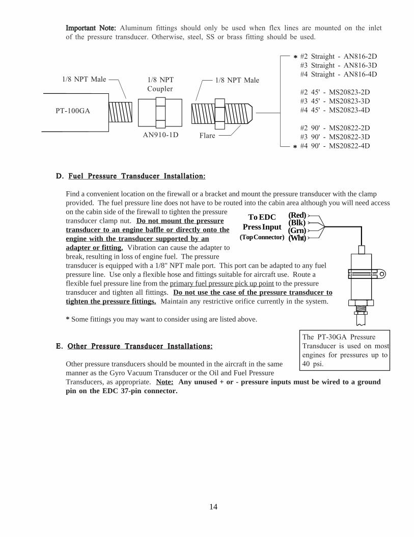
Important Note:Important Note:Important Note:Important Note:Important Note: Aluminum fittings should only be used when flex lines are mounted on the inletof the pressure transducer. Otherwise, steel, SS or brass fitting should be used.
14
PT-100GA
1/8 NPT Male 1/8 NPTCoupler
AN910-1D
#2 Straight - AN816-2D#3 Straight - AN816-3D#4 Straight - AN816-4D
#2 45' - MS20823-2D#3 45' - MS20823-3D#4 45' - MS20823-4D
#2 90' - MS20822-2D#3 90' - MS20822-3D#4 90' - MS20822-4D
1/8 NPT Male
Flare
*
*
D. D. D. D. D. Fuel Pressure Transducer Installation:Fuel Pressure Transducer Installation:Fuel Pressure Transducer Installation:Fuel Pressure Transducer Installation:Fuel Pressure Transducer Installation:
Find a convenient location on the firewall or a bracket and mount the pressure transducer with the clampprovided. The fuel pressure line does not have to be routed into the cabin area although you will need accesson the cabin side of the firewall to tighten the pressuretransducer clamp nut. Do not mount the pressuretransducer to an engine baffle or directly onto theengine with the transducer supported by anadapter or fitting. Vibration can cause the adapter tobreak, resulting in loss of engine fuel. The pressuretransducer is equipped with a 1/8" NPT male port. This port can be adapted to any fuelpressure line. Use only a flexible hose and fittings suitable for aircraft use. Route aflexible fuel pressure line from the primary fuel pressure pick up point to the pressuretransducer and tighten all fittings. Do not use the case of the pressure transducer totighten the pressure fittings. Maintain any restrictive orifice currently in the system.
* Some fittings you may want to consider using are listed above.
E. E. E. E. E. Other Pressure Transducer Installations:Other Pressure Transducer Installations:Other Pressure Transducer Installations:Other Pressure Transducer Installations:Other Pressure Transducer Installations:
Other pressure transducers should be mounted in the aircraft in the samemanner as the Gyro Vacuum Transducer or the Oil and Fuel PressureTransducers, as appropriate. Note: Any unused + or - pressure inputs must be wired to a groundpin on the EDC 37-pin connector.
The PT-30GA PressureTransducer is used on mostengines for pressures up to40 psi.
(Red)(Blk)(Grn)(Wht)
To EDCPress Input
(Top Connector)

15
2.7 Install the CO Detector, G-Sensor and/or Other Available CGR Options:
The CO Guardian Remote Mounted CO Detector, G-Sensor and other CGR options listed on EI’s price sheet areprovided with there own installation instructions. These items should be installed and wired in accordance with theaccompanying instructions. Note: The CO Detector connects to Port 4 or Port 3 Input on the CGR.
2.8 Install the Shunt (for Amps):
An external shunt is a strip of metal, usually mounted on a bakelite base. This metal is made of special alloys toproduce a very small, precise signal when current passes through it. It is not affected by temperature changes.If your aircraft currently has an external shunt you can calibrate your CGR to that shunt. The CGR can becalibrated to match any shunt on the market.
A. A. A. A. A. Determine How the Shunt will be Installed in the Aircraft’s Electrical System:Determine How the Shunt will be Installed in the Aircraft’s Electrical System:Determine How the Shunt will be Installed in the Aircraft’s Electrical System:Determine How the Shunt will be Installed in the Aircraft’s Electrical System:Determine How the Shunt will be Installed in the Aircraft’s Electrical System:
There are two common methods of installing a shunt in an aircraft. One method is with the shunt inthe alternator lead. The other method is with the shunt located in the battery lead. The S-50 shuntthat comes with the CGR-30 package may be installed using either method. The advantages anddisadvantages of each method are listed below.
There are few disadvantages with either method. Although EI’s test pilot has a slight preference forthe alternator lead when using the CGR, ease of installation should be the determining factor in thisinstallation. If more than one shunt is required, a second shunt can be installed through a FM-VA-M-(50 or 300) Functional Module. The Functional Modules come with their own installation instruc-tions.
Installation Method Advantages Disadvantages
Battery Lead: 1. Shows load current on theground (engine off) and duringan alternator failure.
2. All Warning Lights areoperational.
1. Cannot show load current duringflight or when the engine is running.
Alternator Lead: 1. Shows load current duringflight or when the engine isrunning.
2. All Warning Lights areoperational.
1. Cannot show load current whenthe engine is off or during analternator failure.
S0224921
B. B. B. B. B. Install the External Shunt:Install the External Shunt:Install the External Shunt:Install the External Shunt:Install the External Shunt:
The external shunt should be installed in an appropriate location thatminimizes the routing of main cables (refer to figure 1 or 2 as appropriatefor your installation). It should also be mounted in a location whereinadvertent damage cannot occur. If the shunt can be accessed easily, itshould be covered. When mounting the shunt, use self-locking or safety-wired nuts.
Shunt

The signal wires from the shunt to the EDC must be fused a short distance after they leave theshunt. If this is a new installation, install two in-line one-amp fuses, one in each of the signal linesfrom the shunt to the EDC Amp Input.
16
Batt.
Master SwitchContactor
Alternator
F B G
Starter Solenoid
External Shunt
+-
This line may be connected currentlyto the Master Switch Contactor or theStarter Solenoid. In either case itshould be rerouted to the Bus or + sideof the Shunt.
BUS
This is the main lead going to the Bus. It may come fromthe Master Switch Contactor or the Starter Solenoid.
To Starter
To Voltage Regulator
Figure 1: Figure 1: Figure 1: Figure 1: Figure 1: External Shunt Installed in the Battery LeadExternal Shunt Installed in the Battery LeadExternal Shunt Installed in the Battery LeadExternal Shunt Installed in the Battery LeadExternal Shunt Installed in the Battery Lead
Note: The External ShuntNote: The External ShuntNote: The External ShuntNote: The External ShuntNote: The External Shuntshould not be installed in seriesshould not be installed in seriesshould not be installed in seriesshould not be installed in seriesshould not be installed in serieswith the starting current.with the starting current.with the starting current.with the starting current.with the starting current.
Note: Note: Note: Note: Note: If you are replacing an existing ammeter, the shunt may already be mounted in the aircraft. Ifyou already have a shunt installed and know the value of the existing shunt, the CGR can be cali-brated to that shunt.

17
Alternator
F
Starter Solenoid
BUS
To Starter
This is the main lead going to the Bus.It may come from the Master SwitchContactor or the Starter Solenoid.
Figure 2: Figure 2: Figure 2: Figure 2: Figure 2: External Shunt Installed in the Alternator LeadExternal Shunt Installed in the Alternator LeadExternal Shunt Installed in the Alternator LeadExternal Shunt Installed in the Alternator LeadExternal Shunt Installed in the Alternator Lead
This line may be connected to the Bus, MasterSwitch Contactor or the Starter Solenoid.
B
G
-+
External Shunt
Batt.
Note: The Shunt may be installedbefore or after any reversecurrent diode. However, it ispreferable to install it after thereverse current diode as shown.
Reverse Current Diode.(Some aircraft do not have this
diode)
Master SwitchContactor
Aircraft Configuration Drawing #
Fuel injected engine without a fuel return linefrom the fuel servo (most Lycomings).
1229932 or1229931
Fuel injected engine with a fuel return line fromthe fuel servo (most Continentals). 0415941
Carbureted engine with a fuel pump and no fuelreturn line.
1229932 or1229931
Carbureted engine with a fuel pump and a fuelreturn line (requires an FFDM-1 Module).
1229932 or1229931, and1015941
Carbureted engine with a gravity feed fuelsystem (requires an FT-90 Flow Transducer).
1229932 or1229931
Fuel Flow Transducer Selection:
FT-60 (Red Cube): For 0 to 350 HPEngines.
FT-90 (Gold Cube): For 350 to 550HP Engines.
FT-180 (Black Cube): For 550+ HPEngines.
(See the transducer specification forpressure drops at a given flow rate.)
2.9 Install the Fuel Flow Transducer:
Mount the Fuel Flow Transducer using the appropriate drawing found on the following pages.

Note:Note:Note:Note:Note: If your engine is equipped with a pressure carburetor with a fuel return line from the carburetorback to the fuel tank, you will need to install two flow transducers: one in the feed line from the fuelpump to the carburetor and one in the return line from the carburetor back to the fuel tank. Also, a FuelFlow Differential Module (FFDM-1) will need to be installed. See drawings 1229932 and 1015941 onthe following pages.
Note: Note: Note: Note: Note: Insure the fuel flow transducer is appropriate for the horsepower of the engineInsure the fuel flow transducer is appropriate for the horsepower of the engineInsure the fuel flow transducer is appropriate for the horsepower of the engineInsure the fuel flow transducer is appropriate for the horsepower of the engineInsure the fuel flow transducer is appropriate for the horsepower of the engine.
A.A.A.A.A. The transducer output port should be mounted lower, even with or no more than 4" per foot higherthan the carburetor inlet port (or fuel servo on a fuel-injected engine). If this is not possible, a loopshould be put in the fuel line between the Fuel Flow Transducer and the carburetor or fuel servo (seediagram below). This loop is intended to vacate air and keep it from getting trapped in the fueltransducer.
18
Fuel Flow Transducer
1/4" NPT
Note: • The direction of the flow offuel through the transduceris marked on the trans-ducer.
• Mount the transducer withthe wires pointing up, orthe cap with five boltspointing up or the outputpointing up or any combi-nation thereof.
End ViewEnd ViewEnd ViewEnd ViewEnd View Side ViewSide ViewSide ViewSide ViewSide View
If the transducer is more than 4" per foot higherthan the carburetor or fuel servo port, put a loopin the fuel line between the transducer and thecarburetor or fuel servo. This will allow bubblesto vacate the Flow Transducer.
Fuel Flow Trans-ducer Carburetor or
Fuel Servo
OUT
B. B. B. B. B. Do not remove the yellow caps on the flow transducer until the fuel hoses are ready to be installed.
C. C. C. C. C. The flow of fuel through the transducer must follow the direction marked on the transducer.
D. D. D. D. D. The flow transducer must be mounted so the wires exiting the transducer are pointing up, or the capwith five bolts is pointing up, or the output port is pointing up, or any combination thereof.
E. E. E. E. E. Before connecting any hoses, thoroughly clean them and insure they are free of any loose material.High air pressure may be used, however, however, however, however, however, do not allow high air pressure to pass through thedo not allow high air pressure to pass through thedo not allow high air pressure to pass through thedo not allow high air pressure to pass through thedo not allow high air pressure to pass through theflow transducer.flow transducer.flow transducer.flow transducer.flow transducer.
F.F.F.F.F. When mounting a Fuel Flow Transducer, make provisions for the Fuel Pressure Transducer as neces-sary.
G. G. G. G. G. If the flow tranducer is hard mounted to a bracket, DO NOT connect the Black Gound WireDO NOT connect the Black Gound WireDO NOT connect the Black Gound WireDO NOT connect the Black Gound WireDO NOT connect the Black Gound Wire onthe flow transducer. The bracket will provide the necessary ground to the transducer.

19
Fittings:Fittings:Fittings:Fittings:Fittings:
#4 Straight - AN816-4-4D#6 Straight - AN816-6D#8 Straight - AN816-7D
#6 45' - MS20823-6D
#4 90' - MS20822-4-4D#6 90' - MS20822-6D
1/4" NPT1/4" NPT1/4" NPT1/4" NPT1/4" NPT FlareFlareFlareFlareFlare
Hose Fittings:Hose Fittings:Hose Fittings:Hose Fittings:Hose Fittings:
Straight - MS24587-XX, Stratoflex 300-, Aeroquip 400-45' - MS27226-XX, Stratoflex 646- and 640, Aeroquip 98000690' - MS27224-XX, Stratoflex 649- and 643, Aeroquip 980005
NOTE: NOTE: NOTE: NOTE: NOTE: The Stratoflex teflon hose can be much more flexibleand easier to route than most existing hoses. If you have a hard-to-fit installation, you might want to consider this hose.
FlareFlareFlareFlareFlare H o s eH o s eH o s eH o s eH o s e
You may want to consider using some fittings and hoses shown below. Note: DO NOT EXCEED aDO NOT EXCEED aDO NOT EXCEED aDO NOT EXCEED aDO NOT EXCEED atorque of 15 ft. lbs. or screw the fittings tighter than two full turns past hand tight, which-torque of 15 ft. lbs. or screw the fittings tighter than two full turns past hand tight, which-torque of 15 ft. lbs. or screw the fittings tighter than two full turns past hand tight, which-torque of 15 ft. lbs. or screw the fittings tighter than two full turns past hand tight, which-torque of 15 ft. lbs. or screw the fittings tighter than two full turns past hand tight, which-ever happens first.ever happens first.ever happens first.ever happens first.ever happens first.
Important Note:Important Note:Important Note:Important Note:Important Note: Aluminum fittings should only be used when flex lines are mounted on the inlet andoutlet ports of the flow transducer. Otherwise, steel, SS or brass fitting should be used.

20
12/29/93
R.R.
R.R.
None
(IN)(OUT)
From the Fuel Pump(or Fuel Filter on agravity feed system)
To the Carburetor(or Fuel Servo)
Fuel Flow Transducer
Adapter, (1/4" NPT to Fuel Hose) 6" Maximum fromsupport or fitting.
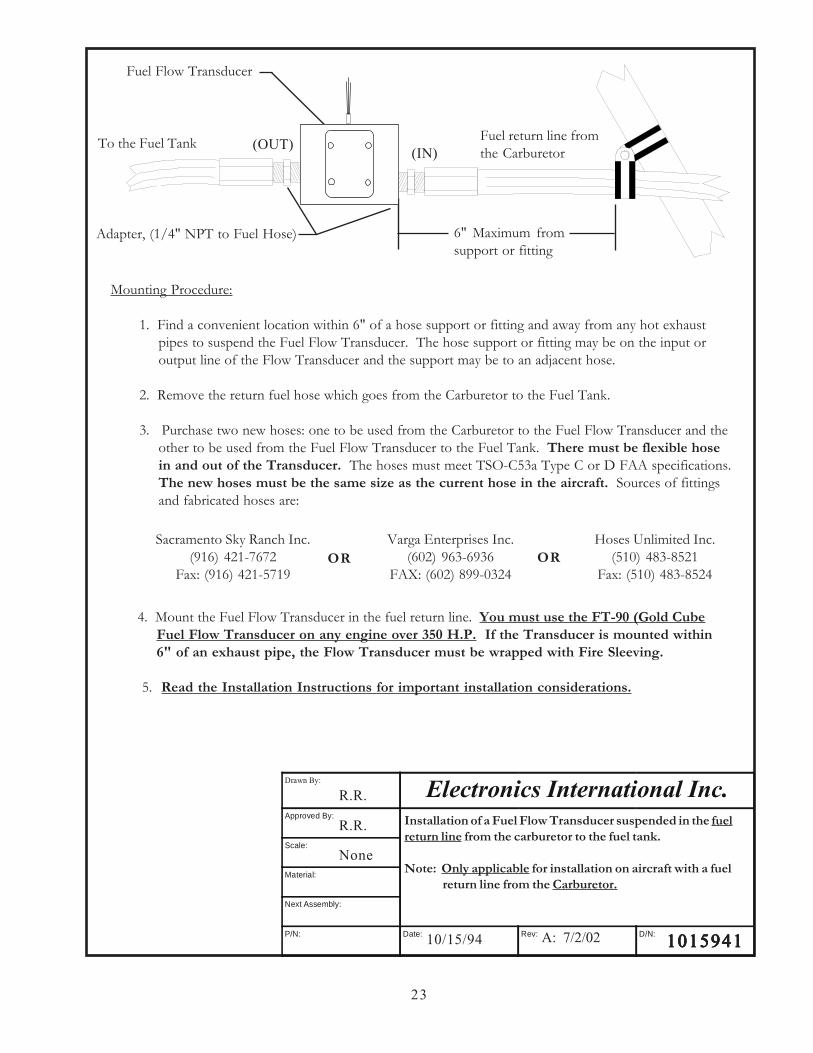
Mounting Procedure:
1. Find a convenient location within 6" of a hose support or fitting and away from any hot exhaustpipes to suspend the Fuel Flow Transducer. The hose support or fitting may be on the input oroutput line of the Flow Transducer and the support may be to an adjacent hose.
2. Remove the fuel hose which goes from the Fuel Pump (or the Fuel Filter on a gravity feed system) tothe Carburetor (or Fuel Servo).
3. Purchase two new hoses: one to be used from the fuel pump (or the Fuel Filter) to the Fuel FlowTransducer and the other to be used from the Fuel Flow Transducer to the carburetor (or FuelServo). There must be flexible hose in and out of the Transducer. The hoses must meet TSO-C53a Type C or D FAA specifications. The new hoses must be the same size as the currenthoses in the aircraft. Sources of fittings and fabricated hoses are:
4. Mount the Fuel Flow Transducer in the fuel line. You must use the FT-90 (Gold Cube) FuelFlow Transducer on a gravity feed system or for any engine over 350 H.P. If the Trans-ducer is mounted within 6" of an exhaust pipe, the Flow Transducer must be wrappedwith Fire Sleeving.
5. Read the Installation Instructions for important installation considerations.Read the Installation Instructions for important installation considerations.Read the Installation Instructions for important installation considerations.Read the Installation Instructions for important installation considerations.Read the Installation Instructions for important installation considerations.
D: 7/2/02 12299321229932122993212299321229932
Sacramento Sky Ranch Inc.(916) 421-7672
Fax: (916) 421-5719
Varga Enterprises Inc.(602) 963-6936
FAX: (602) 899-0324OR OR
Hoses Unlimited Inc.(510) 483-8521
Fax: (510) 483-8524
Installation of a Fuel Flow Transducer suspended in the fuelline from the fuel pump to the carburetor or fuel servo.
Note: Not applicable for a fuel-injected engine with a fuelreturn line (see D/N 0415941).
Drawn By:
Approved By:
Scale:
Material:
Next Assembly:
P/N: Date: Rev: D/N:
Electronics International Inc.Electronics International Inc.Electronics International Inc.Electronics International Inc.Electronics International Inc.

12/29/93 12299311229931122993112299311229931
R.R.
R.R.
None
Installation of a Fuel Flow Transducer on the Firewall and inthe fuel line from the fuel pump to the carburetor or fuel servo.
Note: Not applicable for a fuel-injected engine with a fuelreturn line (see D/N 0415941).
D: 7/2/02
(OUT)(IN)
Fuel Flow Transducer
Bracket
To the Carburetor(or Fuel Servo)
Adapter, (1/4 NPT to Fuel Hose)Adapter, (1/4" NPT to Fuel Hose)
From the Fuel Pump(or Fuel Filter on agravity feed system).
Mounting Procedure:
1. Find a convenient location on the firewall (away from any hot exhaust pipes) and mount a bracketfor the Fuel Flow Transducer. Check both sides of the firewall for clearance before drilling anyholes.
2. Mount the Fuel Flow Transducer onto the Bracket. You must use the FT-90 (Gold Cube) FuelFlow Transducer on a gravity feed system or for any engine over 350 H.P. If the Trans-ducer is mounted within 6" of an exhaust pipe, the Flow Transducer must be wrapped withFire Sleeving.
3. Remove the fuel hose which goes from the Fuel Pump (or the Fuel Filter on a gravity feed system) tothe Carburetor (or Fuel Servo).
4. Purchase two new hoses, one to be used from the fuel pump (or the Fuel Filter) to the Fuel FlowTransducer (making provisions for the fuel pressure transducer as necessary) and the other to be usedfrom the Fuel Flow Transducer to the carburetor (or Fuel Servo). There must be flexible hose inand out of the Transducer. The hoses must meet TSO-C53a Type C or D FAA specifications.The new hoses must be the same size as the current hoses in the aircraft. Sources of fittingsand fabricated hoses are:
Sacramento Sky Ranch Inc.(916) 421-7672
Fax: (916) 421-5719
Varga Enterprises Inc.(602) 963-6936
FAX: (602) 899-0324O RO RO RO RO R
5. Read the Installation Instructions for important installation considerations.
O RO RO RO RO RHoses Unlimited Inc.
(510) 483-8521Fax: (510) 483-8524
Drawn By:
Approved By:
Scale:
Material:
Next Assembly:
P/N: Date: Rev: D/N:
Electronics International Inc.Electronics International Inc.Electronics International Inc.Electronics International Inc.Electronics International Inc.
21

Mounting Procedure:
1. Find a convenient location between the Fuel Servo and FlowDivider and away from any hot exhaust pipes to suspend theFuel Flow Transducer. The Transducer must mounted within6" of a hose support or fitting. The support or fitting may beon the input or output line of the Flow Transducer and thesupport may be to an adjacent hose.
2. Remove the fuel hose which goes from the Fuel Servo to theFlow Divider.
3. Purchase two new hoses: one to be used from the Fuel Servoto the Fuel Flow Transducer and the other to be used from theFuel Flow Transducer to the Flow Divider. There must beflexible hose in and out of the Fuel Transducer. The hosesmust meet TSO-C53a Type C or D FAA specifications. Thenew hoses must be the same size as the current hoses inthe aircraft. Sources of fittings and fabricated hoses are:
Adapter, (1/4" NPTto Fuel Hose)
(IN)
(OUT)
From the Fuel Servo
To the Flow Divider
Sacramento Sky Ranch Inc.(916) 421-7672
Fax: (916) 421-5719
Varga Enterprises Inc.(602) 963-6936
FAX: (602) 899-0324O RO RO RO RO R O RO RO RO RO R
Hoses Unlimited Inc.(510) 483-8521
Fax: (510) 483-8524
4/15/94
R. R.
R.R.
None
Installation of the Fuel Flow Transducer suspended in the fuelline between the Fuel Servo and the Flow Divider.
Note: Only applicable for installation on aircraft with a fuelreturn line from the Fuel Servo.
04159410415941041594104159410415941B: 7/2/02
Drawn By:
Approved By:
Scale:
Material:
Next Assembly:
P/N: Date: Rev: D/N:
Electronics International Inc.Electronics International Inc.Electronics International Inc.Electronics International Inc.Electronics International Inc.
4. Mount the Fuel Flow Transducer in the fuel line. You must use the FT-90 (Gold Cube) Fuel Flow Trans-ducer on any engine over 350 H.P. If the Transducer is mounted within 6" of an exhaust pipe, theFlow Transducer must be wrapped with Fire Sleeving.
5. Read the Installation Instructions for important installation considerations.
22
(IN)(OUT)
Fuel Flow Transducer
Adapter, (1/4" NPT to Fuel Hose) 6" Maximum fromsupport or fitting
Mounting Procedure:
1. Find a convenient location within 6" of a hose support or fitting and away from any hot exhaustpipes to suspend the Fuel Flow Transducer. The hose support or fitting may be on the input oroutput line of the Flow Transducer and the support may be to an adjacent hose.
2. Remove the return fuel hose which goes from the Carburetor to the Fuel Tank.
3. Purchase two new hoses: one to be used from the Carburetor to the Fuel Flow Transducer and theother to be used from the Fuel Flow Transducer to the Fuel Tank. There must be flexible hosein and out of the Transducer. The hoses must meet TSO-C53a Type C or D FAA specifications.The new hoses must be the same size as the current hose in the aircraft. Sources of fittingsand fabricated hoses are:
To the Fuel Tank Fuel return line fromthe Carburetor
4. Mount the Fuel Flow Transducer in the fuel return line. You must use the FT-90 (Gold CubeFuel Flow Transducer on any engine over 350 H.P. If the Transducer is mounted within6" of an exhaust pipe, the Flow Transducer must be wrapped with Fire Sleeving.
5. Read the Installation Instructions for important installation considerations.
Sacramento Sky Ranch Inc.(916) 421-7672
Fax: (916) 421-5719
Varga Enterprises Inc.(602) 963-6936
FAX: (602) 899-0324OR OR
Hoses Unlimited Inc.(510) 483-8521
Fax: (510) 483-8524
10/15/94
R.R.
R.R.
None
Installation of a Fuel Flow Transducer suspended in the fuelreturn line from the carburetor to the fuel tank.
Note: Only applicable for installation on aircraft with a fuelreturn line from the Carburetor.
10159411015941101594110159411015941A: 7/2/02
Drawn By:
Electronics International Inc.Approved By:
Scale:
Material:
Next Assembly:
P/N: Date: Rev: D/N:
23

24
2.10 Install the EI P-300C Fuel Level Probes (OEM or Expermintal Only):
Install the P-300C (Capacitive) Fuel Level Probes in accordance with the aircraft manufacturer’s instructions.
2.11 Install the EI P-300M Fuel Level Sender:
The CGR-30 system can interface with an aircraft’s existing Resistive Fuel Sensors via the RFLM-4 or theseresistive fuel level sensors can be replaced with the P-300M (Magnetic Float) Fuel Level Sender. The signalproduced by the P-300M Sender is a linear voltage output designed to work with the CGR-30 system.
The P-300M’s float arm and travel must match the aircraft’s existing sender’s arm and travel. Due to the lackof information from aircraft manufacturers, the existing sender may need to be removed from the aircraft andsent to Electronics International. In this way the P-300M’s float arm and travel can be matched with theaircraft’s existing sender. Contact Electronics International for further information.The P-300M has the same bolt pattern as resistive fuel senders. The P-300M requires three wires to interfaceto the EDC (resistive senders only use one wire).
Note:Note:Note:Note:Note: Calibrating the CGR-30P to a fuel tank can compensate for nonlinearity in the tank’s shape andnonlinearity in the resistive fuel level sensor. The CGR cannot correct for inconsistent or non-repeatablesignals from resistive fuel level senders. Unfortunately, many older resistive fuel level senders (and in somecases, newer resistive senders) exhibit some of the following problems:
- Variation in the wiper-to-element resistance (CRV).- Stick slip problems with bearings and wiper-to-element contact.- Windup causing jumps in readings.- Weak wiper tension.- Loose or worn bearings, causing fluctuations in tension and resistance.- Worn out wiper.- Corroded wiper.- Corroded or worn element.- Build up of varnish on the wiper and element.- Water logged floats.
If you find inconsistent or inaccurate fuel level readings (due to a defective resistive fuel level sender), youmust have the sender replaced. Inaccurate readings can lead to a dangerous situation. The CGR-30P dependson the fuel level sender for accurate fuel level information. Read the “Important Notice” in the CGR Operat-ing Instructions.
The P-300M is a float type fuel level sender that uses a magnet and pickup device to detect the float positionand produce the signal for the CGR-30 system. The P-300M has no wiper or resistive element and there is notension on the bearing surfaces. It is not subject to the many problems associated with resistive type senders.The P-300M has nothing to wear out or affect inaccurate fuel level readings. Also, the P-300M does notrequire electricity to flow through an element and wiper saturated in fuel, as is the case with resistive senders.

2.12 Install the Resistive Fuel Level Module (RFLM-4-X):
The RFLM-4 is a Resistive Fuel Level Module that provides pull-upresistors for 4 resistive fuel level sensors. This module is required tointerface an EDC Resistive Fuel Level Input to a Resistive Fuel Sensor.
Warring:Warring:Warring:Warring:Warring: DO NOT connect an RFLM-4 to the output of an existingaircraft’s Capacitive System, damage to the system may occur. Thesmall output voltage of an existing capacitive system currently drives afuel level gauge. This output wire should be routed to one of theresistive fuel level inputs on the EDC with NO connection to an RFLMunit.
There are two RFLM-4 modules available. The RFLM-4-12V operateson a 12-volt electrical system and the RFLM-4-24V operates on a 24-volt electrical system. The appropriate model must be used.
Mount the RFLM-4-X to the inside firewall or to an equipment bayunder the aircraft instrument panel. Use the holes in the bottom plateto mount the unit. Only two mounting holes are required.
Note: For each Fuel Level Channel on the EDC you can use either theResistive Input or the Capacitive Input, but not both.
2.13 Install the Voice Alarm Control Panel (OEM Only):
If the voice alarms provided by the CGR are to be used, the AV-17CP Control Panel will need to be installed inthe aircraft instrument panel.
A. Locate the Control Panel and Switch in theAV-17CP packet. Find an appropriate mounting location on the aircraft instrument panel for theControl Panel and Switch. The Switch will require a 3/4" clearance behind the aircraft instrumentpanel.
B. Using the AV-17CP Control Panel as a template, mark the aircraft instrument panel and drill a 1/4"hole for the AV-17CP Switch.
C. Mount the Switch from behind the aircraft instrument panel. Be careful not to damage thesilkscreening on the Control Panel. The Switch must be mounted with the white/orange wire upwhite/orange wire upwhite/orange wire upwhite/orange wire upwhite/orange wire up.....The lock washer should be mounted on the Switch and behind the aircraft instrument panel.
25
To EDC Resistive FuelLevel Inputs (Bottom Connector)
and the Fuel Level Sensor.
AV-17CP, Control Panel
White/Brown
White/Red
White/Orange (OFF)
(ACK)(+5V)To CGR

26
2.14 Install the Intensity Control Pot CP-1A (Optional):
The backlight display intensity of the CGR is controlled byan external source. The input voltage levels for a bright anddim setting on the CGR-30 are programmable. Your existingreostat can provide this signal or you may purchase the CP-1A.
The CP-1A Intensity Control Pot will provide the propervoltage for one or many CGR-30 units and for the externalMaster Warning and Caution lights associated with eachinstrument. To install the CP-1A perform the following:
A. Find an appropriate mounting location on the aircraft instrument panel for the CP-1A Control Pot.The Pot will require a 2" clearance behind the aircraft instrument panel.
B. Mark the aircraft instrument panel and drill a 1/4" hole for the Pot.
C. Mount the Pot from behind the aircraft instrument panel and install the knob.
2.15 Install the Master Warning (red) and Caution (yellow) Lights:
Install the Warning and Caution Lights as follows:
A. Locate the Red (AL-1R) and Yellow (AL-1Y) lights in the kit. Find an appropriate mounting locationwithin 12" of the pilot's visual centerline. The lights will require 3/4" clearance behind the aircraftinstrument panel.
B. The CGR-30P remote lights and placard must be installed in a location where the placard will bereadable in all lighting conditions. Installing the annunciators near an exiting lighting source orinstalling a post light are acceptable methods of compliance, other methods may also be acceptable.
C. Mark the aircraft instrument panel and drill a 5/16" hole for each light. Install the Red Warning Lightand the Yellow Caution Light from behind the aircraft instrument panel.
Note: If the CGR Master Warning and Caution Outputs are connected to other lights or devices, thecurrent must be limited to 0.1 amps. The outputs pull to ground when active.
NutPot
1/4" HoleKnob
Aircraft Instrument Panel
To CGR(Wht/Orng)
CP-1A
To CGR
(Yellow)
To CGR To CP-1A (Intensity Control Pot)
(Red)
To CGR-30 (Dimming Input)

27
2.16 Install the Interface Circuit for a PWM Backlight System (Optional):
If a PWM backlight system will be used tocontrol the CGR-30 screen intensity, place thefollowing circuit in series with the CGR-30backlight wire.
2.17 Install the USB-6A (Optional):
The CGR-30P provides a USB port to upload configuratoin data and to download flight data. The USB-6Aallows the USB port to be mounted on the aircraft instrument panel. Otherwise, the port will only be availablevia a USB connector (dongle) located under the instrument panel. To install the USB-6A, following the in-structions provided with the unit.
2.18 Install the FM-SC or AC-1 Converter (Optional):
The FAA PMA'd FM-SC and AC-1 are used to convert engine data from a FADEC unit to the CGR-30. Toinstall the converter following the instructions provide with the approprate unit.
2.19 Install any Additional Modules (Optional):
If any additional modules are provided with the system, install them at this time using the instructions providewith the modules.
2.20 Install the EDC-33P:
The EDC-33P (Engine Data Converter) converts all of the analog engine signals into serial data which is outputto the CGR display via one wire (5V Serial). The EDC unit measures 4.5" long by 3.5" wide by 2.2" high.There are three 37-pin D-sub connectors that interface to the various probes, modules or direct connections tothe aircraft.
Mount the EDC (with the connectors pointing down) on the insidefirewall under the aircraft instrument panel or in an equipment baywith the connectors pointing down. For a twin-engine aircraft theEDC can be mounted on the opposite side of the firewall of the engineor in the cabin or equipment bay with the connectors pointing down.Use the holes in the bottom plate of the EDC to mount the unit. Besure you will have enough room to connect the three D-sub connectorwire harnesses to the EDC. Note: If you run out of channels on the EDC, a second EDC may be installed andconnected to the CGR.
When routing the EDC wire harnesses refer to the Top, Middle and Bottom "EDC Wiring Work Sheets" foundat the back of this manual. Insure no wires obstruct the freedom of travel of any controls.
PWM Signal
Gnd
To CGR-30 Backlight
100uF, 35V
4.99K, 1%, 1/4W
Top

28
3.03.03.03.03.0Install the EDC Wire HarnessesInstall the EDC Wire HarnessesInstall the EDC Wire HarnessesInstall the EDC Wire HarnessesInstall the EDC Wire Harnesses
andandandandandRoute WiresRoute WiresRoute WiresRoute WiresRoute Wires
3.1 Attach the three EDC 37-pin Wire Harnesses to the EDC:
3.2 Connect the EDC Harness to the Temperature Probes:
3.3 Connect the EDC Harness to the Pressure Transducers:
3.4 Connect the EDC Harness to the Shunt:
3.5 Connect the EDC Harness to the Fuel Flow Transducer:
3.6 Connect the EDC Harness to the Existing Capacitive Fuel Level System:
3.7 Connect the RFLM-4-x Harness to the EDC Connector and to the Resistive FuelLevel Sensors:
3.8 Connect the EDC Harness to the EI P-300C Capacitive Fuel Level Probes:
3.9 Connect the EDC Harness to the EI P-300M Magnetic Fuel Level Senders:
3.10 Connect the EDC Harness (Volts Measurement Pin) to the Bus:
3.11 Connect the EDC Harness to the RPM Signals:
3.12 Set up the EDC for a 4 or 6-Cylinder Engine:
3.13 Connect the EDC Harness to Power and Ground:
3.14 Route the EDC 5V-Serial Wire to the CGR Connector:
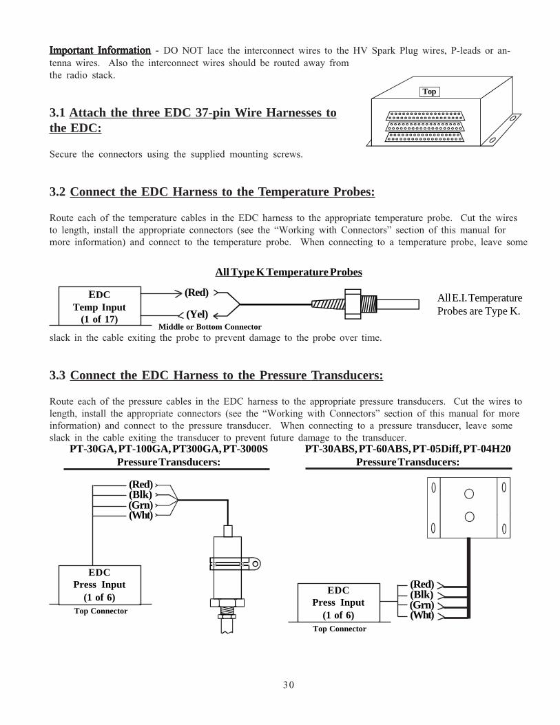
Important InformationImportant InformationImportant InformationImportant InformationImportant Information - DO NOT lace the interconnect wires to the HV Spark Plug wires, P-leads or an-tenna wires. Also the interconnect wires should be routed away fromthe radio stack.
3.1 Attach the three EDC 37-pin Wire Harnesses tothe EDC:
Secure the connectors using the supplied mounting screws.
3.2 Connect the EDC Harness to the Temperature Probes:
Route each of the temperature cables in the EDC harness to the appropriate temperature probe. Cut the wiresto length, install the appropriate connectors (see the “Working with Connectors” section of this manual formore information) and connect to the temperature probe. When connecting to a temperature probe, leave some
30
slack in the cable exiting the probe to prevent damage to the probe over time.
3.3 Connect the EDC Harness to the Pressure Transducers:
Route each of the pressure cables in the EDC harness to the appropriate pressure transducers. Cut the wires tolength, install the appropriate connectors (see the “Working with Connectors” section of this manual for moreinformation) and connect to the pressure transducer. When connecting to a pressure transducer, leave someslack in the cable exiting the transducer to prevent future damage to the transducer.
PT-30GA, PT-100GA, PT300GA, PT-3000SPressure Transducers:
PT-30ABS, PT-60ABS, PT-05Diff, PT-04H20Pressure Transducers:
(Red)(Blk)(Grn)(Wht)
EDCPress Input
(1 of 6)(Red)(Blk)(Grn)(Wht)
EDCPress Input
(1 of 6)Top Connector
Top Connector
Top
All Type K Temperature Probes
All E.I. TemperatureProbes are Type K.
(Red)
(Yel)
EDCTemp Input
(1 of 17)Middle or Bottom Connector

31
3.4 Connect the EDC Harness to the Shunt:
Route the EDC Amps wires to the Shunt. The way the Shunt is installed in the aircraft determines which lugwill be used as "+" (see “Installing the Shunt” in the previous section of this manual). The EDC +Amp Inputwire (orange) should be connected to the small lug on the "+" side of the Shunt. The EDC -Amp Input wire(brown) should be connected to the small lug on the "-" side of the Shunt.
3.5 Connect the EDC Harness to the Fuel Flow Transducer:
Route the fuel flow cable in the EDC harness to the Fuel Flow Transducer. Cut the wires to length, install theappropriate connectors (see the “Working with Connectors” section of this manual for more information) andconnect to the fuel flow transducer. When connecting to the Fuel Flow Transducer, leave some slack in thecable exiting the transducer to prevent future damage to the transducer.
If the flow tranducer is hard mounted to a bracket, DO NOT connect the Black Gound WireDO NOT connect the Black Gound WireDO NOT connect the Black Gound WireDO NOT connect the Black Gound WireDO NOT connect the Black Gound Wire on the flowtransducer. The bracket will provide the necessary ground to the transducer.
Rin
Gnd
EDCResistive Fuel Level
(4ea.)
Bottom Connector
332-Ohms
To Capacitive Signal Out(0 to approx 150 mV)
+10V, (Red, pin 15)Gnd, (Blk, pin 16)Signal (Wht, pin 14)
FT-60, FT-90, FT-180Fuel Flow Transducers:
EDCFuel Flow Input
(1ea.)
Top Connector
3.6 Connect the EDC Harness to the Existing Capacitive Fuel Level System:
The output signal of a capacitive fuel level system (on a certified aircraft) will have a wire connected from thecapacitive system to the fuel level gauge. The signal on this wire will be 0 to approx 150mV DC. The otherside of the gauge will be grounded. Re-route the signal wire (currently connected to the fuel level gauge) toone of the resistive inputs on the bottom connector of the EDC. DO NOT connect an RFLM unit into thissystem, damage to the system may occur. The current fuel level gauge must be remove from the system.
A 332-ohm resistor should be connected from the signal wire to ground. For a CGR-30 STC’d system, thisresistor is integrated into the wire harness supplied with the system.

32
Ch 1 Rin, Pin 2 (Brown)Ch 2 Rin, Pin 3 (Orange)Ch 3 Rin, Pin 4 (Yellow)Ch 4 Rin, Pin 5 (Green)
Ch 1 Rin, Pin 6 (Brown)Ch 2 Rin, Pin 7 (Orange)Ch 3 Rin, Pin 8 (Yellow)Ch 4 Rin, Pin 9 (Green)
EDCResistive Input
(1 of 4)
+Vin, Pin 1, (Red)To Bus (via CGR/EDC Circuit Breaker)
Fuel Tank1
Fuel Tank2
Fuel Tank3
Fuel Tank4
RFLM-4-12V (for a 12Volt system)RFLM-4-24V (for a 24Volt system)
Bottom Connector
Connect only the wires forwhich you have Fuel Tanks.
+5V (Red)Gnd (Black)Cin (White)
P-300C CapacitiveFuel Level Probe
EDCCapacitive Input
(1 of 4)Bottom Connector
3.7 Connect the RFLM-4-x Harness to the EDC Connector and to the Resistive FuelLevel Sensors:
DO NOT connect the RFLM into a capacitive system, damage may occur. Route the appropriate resistive fuellevel input wires (for the number of tanks to be monitored) in the RFLM-4-x harness to the EDC BottomConnector. Plug the wires into the appropriate resistive fuel level channels. The excessive wire can be cut andspliced, bundled and tie wrapped up or cut to length and new D-Sub pin installed (see the “Working withConnectors” section of this manual for more information). Route and connect the corresponding wires in theRFLM-4-x wire harness to the appropriate fuel tank sensors. Route the red wire (in pin 1 of the RFLM-4-xconnector) to the aircraft bus via the CGR/EDC 5-amp circuit breaker.
3.8 Connect the EDC Harness to the EI P-300C Capacitive Fuel Level Probes:
Route the appropriate capacitive fuel level wires (for the number of tanks to be monitored) in the EDC har-nesses to the capacitive fuel level probes. Cut the wires to length, install the appropriate connectors (see the“Working with Connectors” section of this manual for more information) and connect to the capacitive fuellevel probe.
Note: The capacitive fuel level channels are shared with the resistive channels. A single capacitive and resistive channel cannot be used simultaneously.

3.9 Connect the EDC Harness to the EI P-300M Magnetic Fuel Level Senders:
Route the appropriate fuel level wires (for the number of tanks to be monitored) in the EDC harnesses to theP-300M magnetic fuel level senders. Cut the wires to length, install the appropriate conntectors and connect tothe P-300M fuel level sender.
33
To P-lead
EDCRPM Input
(1 of 2)
RingTerminalIsolator(1 of 2)
Bottom Connector
Fuel Tank1
+5V (Red)Gnd (Black)Rin (White)
EDCResistive Input
(1 of 4)Bottom Connector P-300M
Fuel Level Sensor..
Fuel Tank 4
3.10 Connect the EDC Harness (Volts Measurement Pin) to the Bus:
Pin 35 of the EDC top connector monitors bus voltage. Connect this pin to the bus to be monitored.
3.11 Connect the EDC Harness to the RPM Signals:
If the EDC RPM Ch 1 and Ch 2 Inputs are to be connected to a Magneto, Ignition Coilor CDI Ignition System, connect the Ring Terminal Isolators (found in the RPM Isolatorpacket) to the P-leads on the back of the Mag Switch. Connect the EDC RPM Ch 1 andCh 2 wires (White/Brown and White/Orange) to the RPM Isolators.
If the EDC RPM Ch 1 and Ch 2 Inputs are to be connected to an electronic ignitionsystem, connect the EDC RPM Ch 1 and Ch 2 wires (White/Brown and White/Orange)directly to the electronic ignition system RPM output (do not use any isolators). With-out isolators the EDC RPM Ch 1 and Ch 2 Inputs have a 3-volt trigger level and willaccommodate 0 to 5-volt, 0 to 12-volt or 0 to 24-volt signals. If only one RPM signal isavailable, connect only one of the EDC RPM channels.
WARANING: Connecting an EDC RPM input directly to a magneto without an Isolatorwill damage the EDC. Be sure there is an Isolator in each RPM input lead connected to amagneto, ignition coil or CDI ignition.
3.12 Set up the EDC for a 4 or 6-Cylinder Engine:
If the EDC-33P is to be used on a 6-cylinder engine, strap pin 28 to Pin 27 on the EDC Bottom Connector.Leave these pins open for a 4-cylinder engine. This strap may already be installed or can be found in the kit.

Top
5V-Serial Output (pin 6)
Pin 37, Red WirePin 19 Black Wire
Pin 18, White/Green Wire
CGR-30
To Aircraft GroundTo the CGR/EDC 5-amp Circuit Breaker
EDC-33P
Top Connector
3.13 Connect the EDC Harness to Power and Ground:
Route the power wire (Top Connector, pin 37, Red Wire) to the CGR/EDC 5-amp Circuit Breaker. Route theground wire (Top Connector, pin 19, Black Wire) to the aircraft ground.
WARNING: The power wire is RED and is connected to pin 37 on the EDC Top Connector. If aircraft power isconnected to any pin on the EDC other than pin 37, damage to the EDC and any connected transducers may occur.Insure power is provided on pin 37 of the EDC Top Connector before attaching the connector.
3.14 Route the EDC 5V-Serial Wire to the CGR Connector:
Route the 5V-Serial white/green wire to the CGR connector. This wire will be connected to the CGR 5V-Serialinput in a later step. If a second EDC is installed, see the Appendix for connection information.
When routing the CGR wire harness refer to the "CGR-30 25-pin D-Sub Connector Wiring Diagram" found atthe back of this manual. Insure no wires obstruct the freedom of travel of any controls.
34

36
4.0Install the CGR Wire Harness
andRoute the Wires
4.1 Attach the CGR 25-pin D-sub Connector to the CGR:
4.2 Connect the EDC 5V-Serial Output Wire to the CGR 5V-Serial Input Wire:
4.3 Connect the CGR Harness to the Master Warning and Caution Lights:
4.4 Connect the CGR Harness to the Voice Alarm Control Panel (OEM Only):
4.5 Connect the CGR Harness to the Audio Panel (OEM Only):
4.6 Connect the CGR Harness to the Backlight Control Pot:
4.7 Connect the CGR Harness to the Moving Map Data Out from the GPS:
4.8 Connect the CGR Harness to the Fuel Data Input on the GPS:
4.9 Connect the CGR Harness to Power and Ground:
4.10 Connect the CGR Harness to the CO-Guardian CO Detector:

4.1 Attach the CGR 25-pin D-sub Connector to the CGR:
Secure the connector using the supplied mounting screws.
4.2 Connect the EDC 5V-Serial Output Wire to the CGR 5V-Serial Input Wire:
Route the EDC 5V-Serial output wire to the back of the CGR Display, cut the wires to length and splice them tothe appropriate CGR 5V-Serial input wire.
4.3 Connect the Master Warning and Caution Circuits:
If the Warning and Caution Lights are installed, route the CGR Master Warning Out wire (White/Yellow, Pin10) to the Master Warning (Red) Light (AL-1R) White/Yellow wire, cut the wires to length, install the appropri-ate connector and connect to the AL-1R.
Route the CGR Master Caution Out wire (White/Yellow, Pin 23) to the Master Caution (Yellow) Light (AL-1Y)White/Yellow wire, cut the wires to length, install the appropriate connector and connect to the AL-1Y.
Route and connect the CP-1A Backlight Control Pot to the CGR-30P and to the Master Caution and Warninglights.
Route the CP-1A Red wire to the CGR breaker. Route the Black wire to ground.
38
4.4 Connect the CGR Harness to the Voice Alarm Control Panel (OEM Only):
If the voice alarms provided by the CGR are to be used, route the three CGR Voice Control wires to the AV-17CP, cut the wires to length, install the appropriate connectors and connect to the AV-17CP.
Pin 10, Yel
To CGR/EDC5-amp Circuit Breaker
Red Yel
Pin 23, Wht/Yel
CGR-30
Pin 2 (Dimming), Wht/Org
Wht/Org
To Gnd
Wht/Yel Wht/YelRed Red
Blk
Red
DimmingPot
(CP-1A)
Control Panel(AV-17CP)
White/Brown
White/Red
White/Orange (OFF)
(ACK)(+3.3V)CGR
Voice ControlInputs
25
13
12

39
4.5 Connect the CGR Harness to the Audio Panel (OEM Only):
If the voice alarms provided by the CGR are to be used, route the two CGR Voice Warning Out wires to theAudio Panel, cut the wires to length and connect to the Audio Panel Aux input and ground. If an audio input isnot available on the Audio Panel (or an Audio Panel is not installed) you can connect the CGR Voice WarningOut wires to the pilot headset jack. With this installation a 49.9 ohm 1/4 watt resistor will need to be installedin series with the CGR +Voice Warning Out wire and the audio feed wire to the jack.
4.6 Connect the CGR Harness to the Moving Map Data Out from the GPS:
If the CGR is to provide fuel data to the current way point, route the CGR "Moving Map Data In" wire (greenwire in a 4 wire cable) to the Moving Map Data Output Port on the GPS. Cut the wire to length, install theappropriate connector and connect to the GPS port.
+Voice(Wht/Blue, Pin 11)
-Voice(Wht/Gray, Pin 24)
Audio Feed (from Radios)
Pilot's Audio Jack
49.9 Ohms
GndCGR
Voice Output
Moving Map Data In (Grn, Pin 3)Fuel Flow Data Out (Wht, Pin 15)
Wire CableGPSCGR
GPS Input &Output
4.7 Connect the CGR Harness to the Fuel Data Input on the GPS:
If the GPS is capable of displaying fuel data and this feature is to be used, route the CGR "Fuel Data Out" wire(white wire in a 4-wire cable) to the Fuel Data Input Port on the GPS. Cut the wire to length, install the appro-priate connector and connect to the GPS port.

4.8 Connect the CGR Harness to Power and Ground:
Route the power wire (red) to the main bus via a 5-amp Circuit Breaker. Route the ground wire (black) to theaircraft ground.
WARNING:WARNING:WARNING:WARNING:WARNING: The power wire is RED and is connected to pin 1 on the CGR. If aircraft power is connectedto any pin on the CGR other than pin 1, damage to the CGR and any connected hardware may occur. Insurepower is provided on pin 1 of the CGR before attaching the connector.
40
CGRPower & Ground
Power (Red, Pin 1)Gnd (Black, Pin 14)
To Main Bus via 5-amp Breaker.To Aircraft Ground.
4.9 Connect the CGR Harness to the CO-Guardian CO Detector:
If a CO detector was installed, connect the RS232 output from the Remote Mounted 353-201 (experimentalonly) or 452-201-011 (certified) CO Detector to Pin 11 (Port 3 In) on the CGR. Refer to CO-Guardian’sinstallation instructions for further information on the CO Detector.

42
5.0Mandatory System Setup and Checkout
5.1 Power-On Checkout:
5.2 Perform all Steps listed in the "CGR-30P Setup Checklist":
5.3 Ground Run Checkout:
5.4 First Flight Checkout:
5.5 Read the "Warranty/Agreement" and the "Important Notice":

5.1 Power-On Checkout:
Turn the aircraft master switch on. The CGR will power up and perform a system test. After approximately 15seconds the CGR will display the “Main Engine” screen with an Warning and Add Fuel Message. Press anybutton to continue. If you have a problem with any of the following steps, see the Troubleshooting section ofthis manual. Perform only the checks applicable to your configuration.
A. Check the RPM for a reading of 000.B. Check the M.P. for the following reading:
Current BARO less 0.1"Hg for every 100 feet elevation above sea level.C. Check Fuel Flow for a reading of 00.0.D. Check Oil Pressure for a reading of 00.E. Check Oil Temp to read near ambient temperature.F. Check Volts for proper reading.G. Check Amps for proper reading.H. Check all EGT’s to read near ambient temperature.I. Check all CHT’s to read near ambient temperature.J. Check OAT to read ambient temperature.K. Check all other functions on the Main and System screen to operate properly.
Note:Note:Note:Note:Note: Fuel Levels may not read properly until they have been calibrated.
5.2 Perform all Steps listed in the "CGR-30P Installation Checklist":
A CGR-30P Installation Checklist is provided on blue tag board. Each step listed in this checklist must be com-pleted before continuing with this installation.
5.3 Ground Run Checkout:
Start the aircraft engine. Check that the values for each function displayed on the CGR are proper for "engineon" operation. Any problem with a specific function will be associated with a probe, cable or interconnectcable between the probe and the EDC for that function. If you have a problem with any of the following steps,see the Troubleshooting section of this manual. Perform only the checks applicable to your configuration.
A. Check the RPM.B. Check the M.P.C. Check Fuel Flow.D. Check Oil Pressure.E. Check Oil Temperature.F. Check Fuel Level for each Tank.G. Check Volts.H. Check Amps.I. Check all EGTs.J. Check all CHTs.K. Check OAT.L. Check all Annunciators.M. Check all other functions on the Main and System screen.
44

45
Turn the engine off. Inspect the entire system to be certain there is no interference with controls. Also, checkfor loose fittings, proper connections, clamps, probes, and inspect for leaks, chafing, obstructions, heat damageand anything that may cause unsafe flight. Check that all fittings are tight.Check that all fittings are tight.Check that all fittings are tight.Check that all fittings are tight.Check that all fittings are tight. Loose fitting can causeengine and/or aircraft damage and possibly personal injury.
5.4 First Flight Checkout:
Prepare the aircraft for flight. Fly the aircraft in the pattern. Check for proper operation of each functiondisplayed on the CGR. Land the aircraft and perform the following checks as soon as possible:
A. Check all fittings, hoses and transducers for leaks.B. Check all fittings, hoses, wires, system components and hardware to be secure and not chaffing.C. Check for interference to any controls.D. Check for any unsafe condition.
Do not release the aircraft for normal operation until all steps in this document have been performed and theaircraft is safe to fly.
5.5 Read the "Warranty/Agreement" and the "Important Notice":
Require the pilot to read the "Warranty/Agreement" and the "Important Notice" located in the front of the"Operating Instructions" before releasing the aircraft for flight.

46
6.0Installation Data
6.1 Instructions for Continued Airworthiness (ICA):
6.2 Airworthiness Limitations:
6.3 Installing a D-sub Pin onto a TC or Tin Copper Wire:
CGR-30P Work Sheet, 25-pin D-sub Connector
EDC Wiring Work Sheet, Top Connector (Back View)
EDC Wiring Work Sheet, Middle Connector (Back View)
EDC Wiring Work Sheet, Middle Connector (Back View)
EDC Template

6.1 Instructions for Continued Airworthiness (ICA):
The Instructions for Continued Airworthiness (ICA) are located in the Electronics International document06211301 "CGR-30P & CGR-30C Instructions for Continued Airworthiness". If you need an additional copyof the CGR-30P ICA please visit: www.Buy-Ei.com or call (541) 318-6060.
6.2 Airworthiness Limitations:
The Airworthiness Limitations section is FAA approved and specifies maintenance required under CFR 43.16 and91.403 of the Code of Federal Aviation Regulations unless an alternative program has been FAA approved.
Operational:
The conditions and tests required for TSO approval of the CGR-30 are minimum performance stan-dards. It is the responsibility of those installing this system either on or within a specific type or classof aircraft to determine that the aircraft installation conditions are within the TSO standards. TSOarticles must have separate approval for installation in an aircraft. The CGR-30 may be installed onlyif performed under 14 CFR part 43 or the applicable airworthiness requirements. There are no furtherspecific operating limitations of this system.
Installation:
The CGR-30 system is to be installed in accordance with the current CGR-30 Installation Instructions,AC 43.13 and any other appropriate FAA approved practices or guidelines. These instructions alongwith FAA approved material insure the system will meet the requirements of the applicable TSOsonce installed in an aircraft. There are no further specific installation limitations of this system.
6.3 Installing a D-sub Pin onto a TC or Tin Copper Wire:
D-sub pins are used in the D-sub connectors found on the EDC and the CGR. Most of these pins have alreadybeen installed on the appropriate wires and inserted into the proper connector. Installing a D-sub pin requires aD-sub crimp tool. Most electronic stores carry a reasonably priced D-sub crimp tool that will perform a goodcrimp but a 4 to 5 pound pull test must be performed. To install a D-sub pin onto a 20 ga. Tin Copper Wire,perform the following steps:
A. Strip the insulation back 1/8.” Be careful not to knick the wire.
B. Insert the pin into the 24 ga. D-sub Pin Crimper. The crimpers have two cavities; the smaller one isused to crimp the bare wire and the slightlylarger one is used to crimp around the insula-tion. Check that the pin is inserted into thecrimpers properly. Also, the ears on the pinmust be facing into the center of the crimp toolcavity to produce a good crimp. If the pinrotates even a little during crimping, the connec-tion will be unreliable.
Insulation
E.I. D-sub Pin
Bare Wire
48

C. Insert the wire into the pin. Check that the insulation is in the strain relief crimp area but not in the barewire crimp area. Crimp the pin onto the wire. A good crimp is very importantA good crimp is very importantA good crimp is very importantA good crimp is very importantA good crimp is very important. . . . . Poor crimpsPoor crimpsPoor crimpsPoor crimpsPoor crimpswill cause jumpy readings and are the biggest source of problemswill cause jumpy readings and are the biggest source of problemswill cause jumpy readings and are the biggest source of problemswill cause jumpy readings and are the biggest source of problemswill cause jumpy readings and are the biggest source of problems.....
D. Pull Test: Pull (approximately 4 to 5 pounds) on the wire near theconnector with one hand while holding the connector with the otherhand. If the wire pulls out of the connector, you must start over usinga new connector.
E. A well soldered connection at the crimp can be reliable. Soldering aTC wire requires a lot of heat to produce a good solder connection.Also, when soldering a TC wire each wire should be scraped with aknife to expose fresh metal just before crimping and applying solder.Fluxing the TC wire can also help. Do not use acid core solder oracid flux.
Crimp Cavity
Pin Ears face Down
End Viewof
the D-sub Pin in the Crimp Tool
49
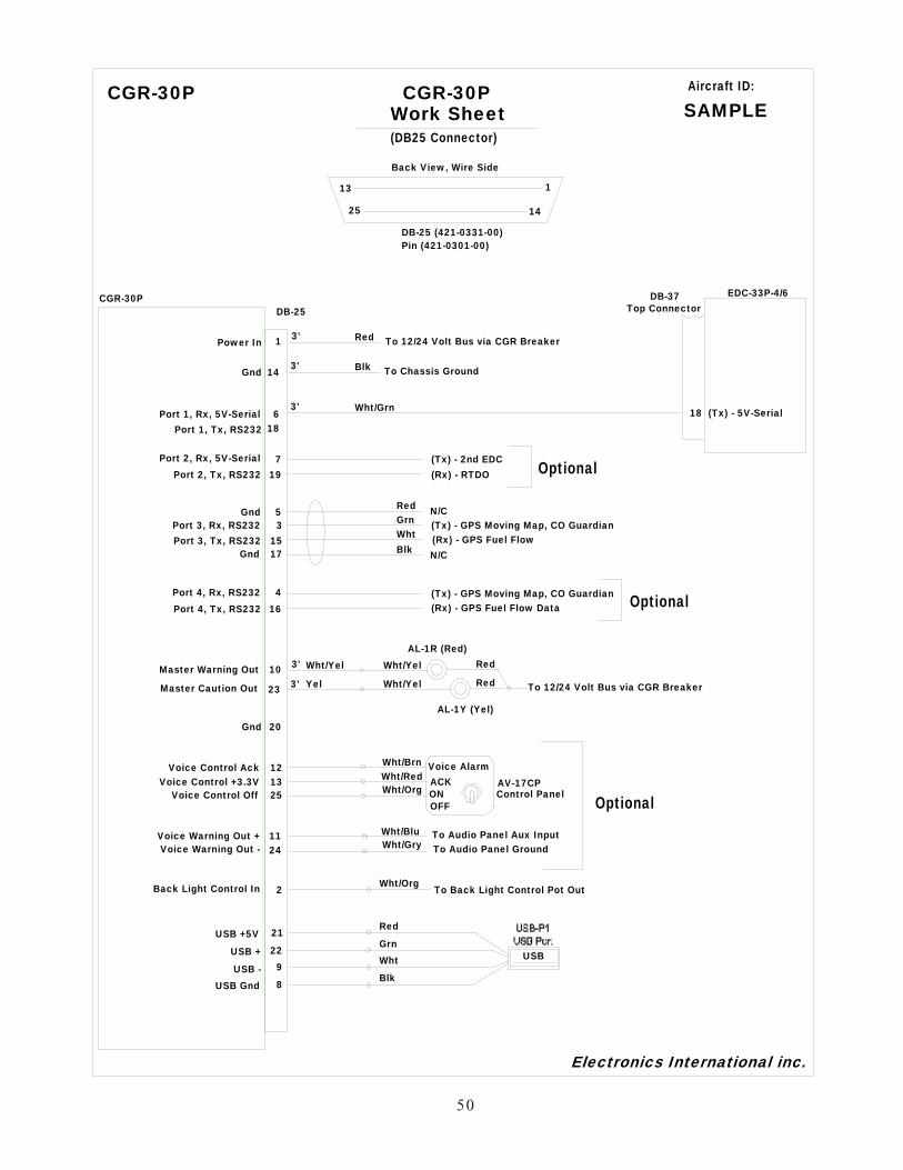
5650
Work Sheet(DB25 Connector)
Power In 1 To 12/24 Volt Bus via CGR Breaker
Port 1, Rx, 5V-Serial 6
EDC-33P-4/6CGR-30PDB-25
DB-37
18
Gnd 17
Gnd 5
Master Warning Out 10
Master Caution Out 23
(Tx) - 5V-Serial
Back View, Wire Side
13
14
1
Electronics International inc.
DB-25 (421-0331-00)Pin (421-0301-00)
3'
3'
Aircraft ID:
SAMPLE
25
Gnd 14 To Chassis Ground3'
Port 2, Rx, 5V-Serial 7Port 2, Tx, RS232 19
AL-1R (Red)
AL-1Y (Yel)
Wht/Yel
Wht/Yel To 12/24 Volt Bus via CGR Breaker
Voice Control Ack 12Voice Control +3.3V 13
Voice Control Off 25
Wht/BrnWht/RedWht/Org
Voice AlarmACKONOFF
Voice Warning Out + 11Voice Warning Out - 24
Wht/BluWht/Gry
To Audio Panel Aux InputTo Audio Panel Ground
3'
3'
WhtBlk
GrnRed
Wht/Yel
Yel
Red
Blk
Wht/Grn
Back Light Control In 2 Wht/Org
(Tx) - 2nd EDC(Rx) - RTDO
AV-17CPControl Panel
Red
Red
N/C
N/C
CGR-30P
Optional
CGR-30P
Top Connector
Port 1, Tx, RS232 18
Port 3, Rx, RS232 3Port 3, Tx, RS232 15
(Tx) - GPS Moving Map, CO Guardian(Rx) - GPS Fuel Flow
Port 4, Rx, RS232 4Port 4, Tx, RS232 16
(Tx) - GPS Moving Map, CO Guardian Optional(Rx) - GPS Fuel Flow Data
Optional
To Back Light Control Pot Out
USB +5V 21 Red
USB + 22 Grn
USB - 9 Wht
USB Gnd 8 Blk
USB
Gnd 20

51
EDC Work SheetTop Connector
Power 37 To 12/24 Volt Bus via CGR BreakerGnd 19 To Chassis Ground
(Tx) - 5V-Serial 1836
CGR-30
EDC-33PDB-37
DB-25
6
EDC-33P
Volts 35 To Aircraft Bus to be Measured (via breaker)
+ Amps 32- Amps 33 S-50 Shunt
+10V 15Gnd 16
Signal In 14
- Signal In 2
Fuel Flow
Flow Transducer
FT-60
Existing Inline Fuses
+5V 20Gnd 21
+ Sigal In 3Pressure Ch1
RedBlkGrnWht
RedBlkWht
M.P.
- Signal In 4
+5V 22Gnd 23
+ Signal In 5Pressure Ch2
RedBlkGrnWht
Fuel PressurePT- 30GA
- Signal In 6
+5V 24Gnd 25
+ Signal In 7Pressure Ch3 PT- 100GA
RedBlkGrnWht
Oil Pressure
- Signal In 8
+5V 26Gnd 27
+ Signal In 9Pressure Ch4
- Signal In 10
+5V 28Gnd 29
+ Signal In 11Pressure Ch5
- Signal In 12
+5V 30Gnd 31
13Pressure Ch6
DB-37 Back View, Wire Side
37
19
20
1
1
17
34
Extra Gnd
Do Not Use
Do Not Use
Electronics International inc.
*1 Unused Pressure ChannelInputs Must Be Grounded.
Notes:
DB-37 (421-0337-00)Pin (421-0301-00)
*1
3'
3'
6'
6'
3'
6'
6'
Aircraft ID:
Sample
+ Signal In
PT-05Diff
RedBlkGrnWht
Vac3'
RedBlk
OrgBrn
Wht/Red
Wht/Grn
PT- 30ABS
Fuel Flow
Amps
RS422 -B OutPort 1, Rx5V-Serial
*1

EDC Work SheetMiddle Connector
+ In (Yel) 321
EDC-33PDB-37
EDC-33P-4/6 Aircraft ID:
1
11
12
Extra Gnd
Electronics International inc.
- In (Red)Temp Ch 2
+ In (Yel) 220- In (Red)
Temp Ch 1
+ In (Yel) 523- In (Red)
Temp Ch 4
+ In (Yel) 422- In (Red)
Temp Ch 3
+ In (Yel) 725- In (Red)
Temp Ch 6
+ In (Yel) 624- In (Red)
Temp Ch 5
+ In (Yel) 927- In (Red)
Temp Ch 8
+ In (Yel) 826- In (Red)
Temp Ch 7
(Best for OAT)
Temp Comp + In 1028Gnd
Temp Comp Diode Network (TCD-1)
+ In (Yel) 1432- In (Red)
Temp Ch 10
+ In (Yel) 1331- In (Red)
Temp Ch 9
+ In (Yel) 1634- In (Red)
Temp Ch 12
+ In (Yel) 1533- In (Red)
Temp Ch 11
+ In (Yel) 1735- In (Red)
Temp Ch 13
(Do Not Remove)
29
30
Extra Gnd
Extra Gnd
Extra Gnd
Extra Gnd
RedYel
TC Extension Wire OATP-128
37
19
20
1
DB-37 Back View, Wire Side
EGT 1P-110
EGT 2P-110
EGT 3P-110
RedYel
TC Extension Wire
RedYel
TC Extension Wire
RedYel
TC Extension Wire
EGT 4P-110RedYel
TC Extension Wire
EGT 5P-110RedYel
TC Extension Wire
EGT 6P-110RedYel
TC Extension Wire
RedYel
TC Extension Wire Oil TempP-120
RedYel
TC Extension Wire CHT 1P-100
+ In (Yel) 1836- In (Red)
Temp Ch 14
+ In (Yel) 1937- In (Red)
Temp Ch 15
RedYel
TC Extension Wire CHT 2P-100
RedYel
TC Extension Wire CHT 3P-100
RedYel
TC Extension Wire CHT 4P-100
RedYel
TC Extension Wire CHT 5P-100
RedYel
TC Extension Wire CHT 6P-100
6'
6'
6'
6'
6'
6'
6'
6'
6'
6'
6'
6'
6'
6'
SAMPLE*1 Unused Pressure Channel
Inputs Must Be Grounded.
Notes:
for shields.-- Extra Gnds maybe used
may be used for annunciators.-- Unused Temp Channels
DB-37 (421-0337-00)Pin (421-0301-00)
52
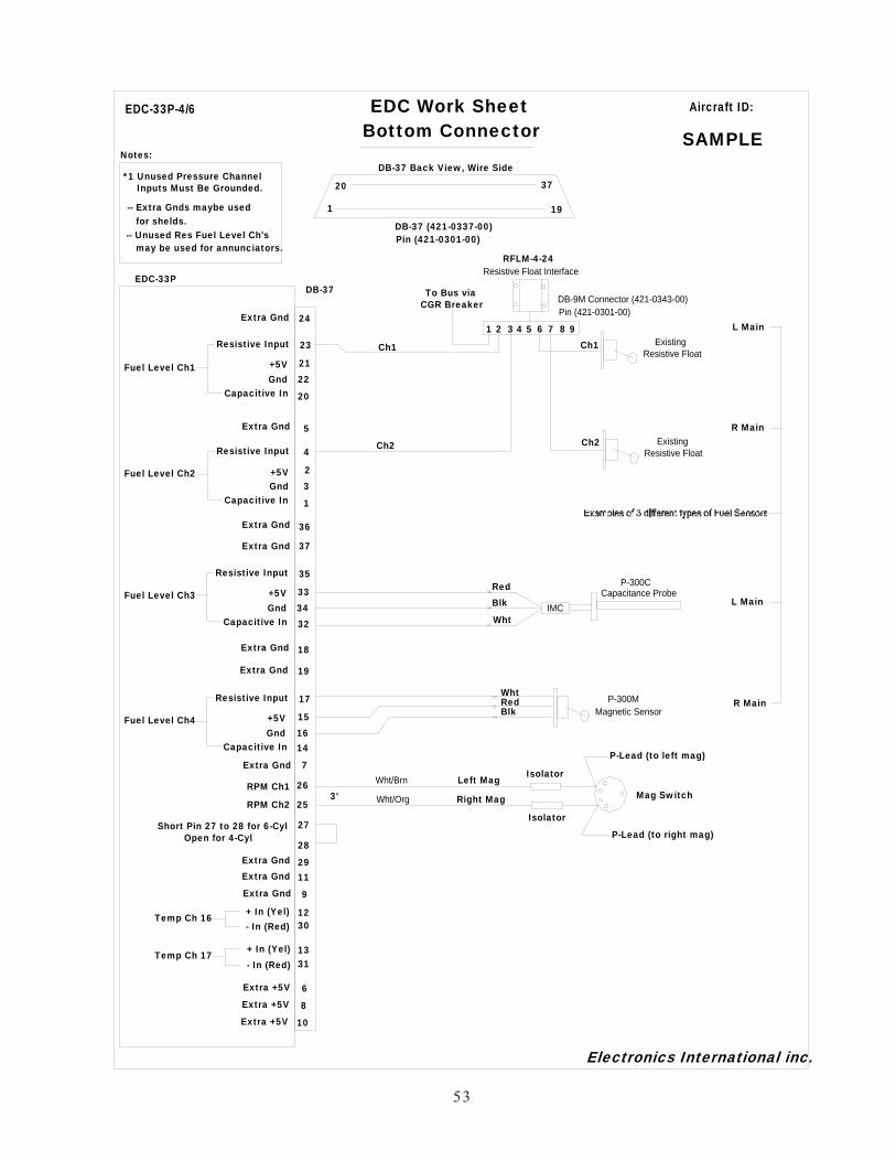
53
EDC Work SheetBottom Connector
2122
EDC-33PDB-37
EDC-33P-4/6
37
19
20
1
Extra Gnd
*1 Unused Pressure ChannelInputs Must Be Grounded.
Electronics International inc.
Notes:DB-37 Back View, Wire Side
23Resistive Input
20
Extra Gnd
Extra Gnd
Extra Gnd
Extra Gnd
+5VFuel Level Ch1Gnd
Capacitive In
3334
35Resistive Input
32
+5VFuel Level Ch3Gnd
Capacitive In
23
4Resistive Input
1
+5VFuel Level Ch2Gnd
Capacitive In
1516
17Resistive Input
+5VFuel Level Ch4Gnd
Capacitive In 14
26
25
RPM Ch1
RPM Ch2
5
7
18
19
24
27
28
36
37
Extra Gnd
for shelds.-- Extra Gnds maybe used
Extra Gnd
Short Pin 27 to 28 for 6-Cyl
RFLM-4-24
1 2 3 4 5 6 7 8 9
CGR BreakerTo Bus via
Ch1 Ch1
Ch2 Ch2
ExistingResistive Float
ExistingResistive Float
L Main
R Main
Resistive Float Interface
P-300MMagnetic Sensor
R Main
P-300CCapacitance Probe
IMCL Main
RedBlk
Wht
may be used for annunciators.-- Unused Res Fuel Level Ch's
Open for 4-Cyl
+ In (Yel) 1230- In (Red)
Temp Ch 16
+ In (Yel) 1331- In (Red)
Temp Ch 17
Extra +5V 6Extra +5V 8
Extra Gnd 9
Extra +5V 10
Extra Gnd 11
Extra Gnd 29
Mag SwitchLeft Mag
Right Mag
Isolator
P-Lead (to left mag)
P-Lead (to right mag)
Isolator
Wht/Brn
Wht/Org3'
RedBlk
Wht
Aircraft ID:
SAMPLE
DB-37 (421-0337-00)Pin (421-0301-00)
DB-9M Connector (421-0343-00)Pin (421-0301-00)

0.0
00
0.2
75
0.5
50
5.3
00
5.5
75
5.8
50
0.550
3.160
3.710
3.160
0.550
0.000
2.350
54

56
7.0Troubleshooting
7.1 CGR or EDC Problem:
7.2 Pressure Problem with one Function:
7.3 Temperature Problem on all Channels:
7.4 Temperature Problem with one Function:
7.5 RPM Problem:
7.6 Fuel Flow Problem:
7.7 Amp Problem:
7.8 Resistive Fuel Level Problem:
7.9 Capacitive Fuel Level Problem:
7.10 Voltage Problem:

58
Troubleshooting the CGR system can be relatively simple. First the CGR must be powered-up. This requiresonly a power and ground connection to the CGR. Next the EDC needs to be powered-up and communicatingwith the CGR. Power and ground are supplied to the EDC on two wires and the EDC communicates with theCGR on one 5V-Serial wire. A "COM" error will be displayed if the EDC is not communicating with the CGR.
The rest of the system is made up of individual functions performing independently of each other. A problemwith a pressure channel will most likely be found in the connection to the transducer, the wire from the trans-ducer to the EDC or the EDC connection. This same scenario is true for all the functions. Rarely is there anyproblems with the EDC or CGR. In some cases the problem can be in the setup programming of the CGR.
7.1 CGR or EDC Problem:
The CGR and EDC require power and ground to operate. The EDC also requires one 5V-Serial wire to com-municate with the CGR. The EDC also supplies power to the Fuel Flow, Fuel Level, and Pressure Transducers.If these power wires become shorted, the EDC operation will be affected.
A. Symptom:A. Symptom:A. Symptom:A. Symptom:A. Symptom: The CGR does not power up.
1. Problem: The Power or Ground wire is open or not connected properly.
a) Action: Measure the voltage on the power and ground wires. Ohm the ground wire toground. Look for a short.
B. Symptom:B. Symptom:B. Symptom:B. Symptom:B. Symptom: “COM” is displayed for the digital value for most functions. The EDC is not communicat-ing with the CGR.
1. Problem: One of the EDC external +5 volt power supplies on the Bottom Connector is shorted toground.
a) Action: Remove the Bottom Connector. If the COM error goes away, look for a short onone of the +5 volt wires.
2. Problem: The Power or Ground wire to the EDC is open or not connected properly.
a) Action: Measure the voltage on the appropriate EDC pins. Ohm the Black ground wire toground.
3. Problem: The EDC +10 volt or one of the +5 volt supplies on the Top Connector is shorted toGround.
a) Action: Measure the +10 volt and +5 volt supplies on the Top Connector. If one of thevoltages is low, use an ohmmeter to find the problem. If all wires ohm properly(>100 ohm when disconnected from the EDC), the Power or Ground wire to the TopConnector may be open.
4. Problem: The 5V-Serial wire from the EDC to the CGR may be open.
a) Action: Inspect the wire. Remove the connectors from the EDC and the CGR and check forcontinuity.

59
Symptom:Symptom:Symptom:Symptom:Symptom: “REF” is displayed for the digital value for all temperature functions.
1. Problem: The Middle Connector on the EDC is loose or not connected. The Reference Diode onpins 10 and 28 of the EDC Middle Connector is damaged. Note: Pin 28 should measure0 volts and pin 10 should measure around .6 volts.
a) Action: Inspect the EDC Middle Connector and measure the voltage on pins 10 and 28.
Symptom:Symptom:Symptom:Symptom:Symptom: “OVR” is displayed for the digital value for a function.
1. Problem: If a channel on the EDC is over ranged (>2.5 volts between the “+” and “-” inputs), an“OVR” will be displayed for that function. This can happen on a channel that is used tomonitor an Annunciator, Flap or Trim function. The max input voltage for any tempera-ture or pressure channel is +5 volts to ground. The maximum differential voltage is 2.5volts. The VI-221 is used to drop the voltage when measuring signals that switch fromground to bus voltage.
a) Action: Measure the voltage on the EDC “+” and “-” inputs for the function with the prob-lem.
7.2 Pressure Problem with one Function:
Pressure is measure on the aircraft with a pressure transducer. Power (+5 volts on the Red wire) and ground(Black wire) is supplied to the transducer and a differential signal (proportional to the pressure) is supplied tothe EDC on the White and Green wires.
Symptom:Symptom:Symptom:Symptom:Symptom: Inaccurate, jumpy or zero reading.
1. Problem: One of the four wires from the Pressure Transducer to the EDC is open.
a) Action: Measure the voltage on each transducer wire at the Pressure Transducer. Thevoltage on each wire is as follows: Red wire = +5 volts, Black wire = 0 volts, Greenwire = 2.5 volts and White wire = 2.5 volts.
Short the Green wire to the White wire and look for a zero pressure reading. If youdo not get a zero reading, you may have an open wire.
Ohm the Black, Green and White wires at the pressure transducer to ground. TheBlack wire should be grounded, the Green and White wires should not.
7.3 Temperature Problem on all Channels:
Temperature is measured using a temperature probe with type K thermocouple (TC) wire. When the TCjunction in the tip of the probe is heated, a small signal (approx. 23 micro volts per ‘F) is produced and moni-tored by the EDC on two extension wires. These extension wires must be made of type K TC material.
When measuring temperature with TC material an ambient reference temperature must be provided. This isdone with a reference diode located on pins 10 and 28 of the EDC Middle Connector. The ambient tempera-ture is added to the temperature measured at the TC junction.

60
Symptom:Symptom:Symptom:Symptom:Symptom: Inaccurate, jumpy or zero readings on all channels.
1. Problem: The Reference Diode on pins 10 and 28 of the EDC Middle Connector is damaged.
a) Action: Measure the voltage on the Reference Diode. Pin 28 = 0 volts and pin 10 = approx.0.5 volts.
2. Problem: One of the temperature input channels is over voltaged. This can happen on a channelthat is used to monitor an Annunciator, Flap or Trim function. The max input voltagefor any temperature or pressure channel is +5 volts. The VI-221 is used to drop thevoltage when measuring signals that switch from ground to bus voltage.
a) Action: Measure the voltage on each of the temperature channels.
7.4 Temperature Problem with one Function:
Temperature is measured on the aircraft using a temperature probe with type K thermocouple (TC) wire. Whenthe TC junction in the tip of the probe is heated, a small signal (approx. 23 micro volts per ‘F) is produced andmonitored by the EDC on two extension wires. These extension wires must be made of type K TC material.
When measuring temperature with TC material an ambient reference temperature must be provided. This isdone with a reference diode located on pins 10 and 28 of the EDC Middle Connector. The ambient tempera-ture is added to the temperature measured at the TC junction.
Symptom:Symptom:Symptom:Symptom:Symptom: Inaccurate, jumpy or zero reading.
1. Problem: One of the two wires from the Temperature Probe to the EDC is open or shorted toground.
a) Action: Remove the extension cable from the probe. Ohm both wires to ground. Each wireshould measure 12.1K ohms to ground.
2. Problem: The temperature probe has a problem.
a) Action: Ohm between the two leads of the temperature probe. You should get a short (<10ohms)
Ohm one lead of the probe to ground. You should get an open (> 100K ohms).
7.5 RPM Problem:
For an engine with magnetos, a pulse is produced on the P-lead for each power stroke of the engine (threepulses per revolution for a six cylinder engine). The pulses can be in the hundreds of volts. An Isolator isconnected between the P-lead and the EDC RPM inputs. The EDC monitors both magnetos.
The RPM reading for each RPM channel can be viewed in the "Function Configuration" screen found in the"System Config Screens Menu." This screen can be very helpful when troubleshooting.

61
Symptom:Symptom:Symptom:Symptom:Symptom: Inaccurate, jumpy or zero reading.
1. Problem: An Isolator was NOT used between the EDC RPM channel and the P-lead at the back ofthe Mag Switch. The signal on the P-lead is hundreds of volts and if an isolator is notused in series with this wire, damage to the RPM input on the EDC could occur.
a) Action: Check that there is an Isolator(s) in line with the RPM signal wires from the EDC.
If only one RPM channel is working, swap the wires to the EDC RPM channel andsee if the problem follows the EDC channel or the wire to the P-lead.
2. Problem: The Isolators in line with the EDC are incorrect.
a) Action: If the RPM reading is jumping high, add a “47” or “79” Isolator in series with theexisting Isolator. The signal from the P-lead is too strong.
If the RPM signal is from an electronic ignition, there should NOT be any Isolatorsin the wire to the EDC. The EDC RPM input triggers at 3 volts.
7.6 Fuel Flow Problem:
Fuel Flow is measured using a Flow Transducer. Power (+10 volts on the Red wire) and ground (Black wire) issupplied to the transducer from the EDC. A rotor in the transducer spins and produces pulses (0 to +5 volts) onthe White wire. The +5 volts portion of the pulse on the White wire comes from a pull-up resistor in the EDC.The K-factor found in the “Fuel K-Factor" screen calibrates the pulses to produce a flow rate.
Symptom:Symptom:Symptom:Symptom:Symptom: Inaccurate readings.
1. Problem: The K-factor is incorrect.
a) Action: Check that the K-factor (found in the “Fuel K-Factor" screen) is correct for thetransducer installed in the aircraft (FT-60 red cube = 68,000, FT-90 gold cube =33,800 and the FT-180 black cube = 22,400).
Symptom:Symptom:Symptom:Symptom:Symptom: Inaccurate, jumpy or zero reading.
1. Problem: A wire is open, shorted or mis-wired.
a) Action: Measure the voltage on the transducer wires from the EDC at the Flow Transducer.The Red lead = +10 volts, Black wire = 0 volts, White wire = + 5 volts with theWhite wire removed from the flow transducer.
Ohm the Black wire to ground. The Black wire must be shorted to ground (< 10ohms).
Rapidly tap the White transducer wire to ground. A small fuel flow reading shouldshow on the CGR.

62
1. Problem: The rotor in the Fuel Flow Transducer is blocked.
a) Action: Remove the Flow Transducer from the aircraft. Lightly blow into the transducer andcheck for the rotor to spin freely. Check for a Fuel Flow reading on the CGR whenthe rotor is spinning.
If the rotor in the Flow Transducer does not spin, hold the transducer over whitepaper and tap at all angles. Debris can lodge in the transducer and block the rotor.
7.7 Amp Problem:
Amps are measured on the aircraft using a Shunt. A Shunt has very low resistance and produces a differentialvoltage on the two signal wires connected to the Shunt. The differential voltage is proportional to the amper-age flowing through the Shunt (50 mV at 50 Amps for the S-50 Shunt). In series with the two signal wires aretwo fuses to protect the wires form catching fire in case of a short. These fuses should be located a shortdistance from the Shunt. The wires are then routed to the EDC Amp input.
Symptom:Symptom:Symptom:Symptom:Symptom: Inaccurate, jumpy or zero reading.
1. Problem: A wire, fuse or fuse connection is open, shorted or mis-wired.
a) Action: Remove one of the signal wires on the Shunt and connect it to the other signal wire.This will short the two signal wires together. The CGR should read 0.0 amps. Acommon problem is with the fuses or fuse holders in line with each Amp signal wirefrom the Shunt to the EDC. The fuses should be located a short distance from theshunt. Inspect the wires, fuses and fuse holders.
7.8 Resistive Fuel Level Problem:
Fuel can be measured in a fuel tank using a Resistive Float Sensor. The sensor must be connected to a RFLM(Resistive Fuel Level Module). This module provides a pull-up resistor to produce a voltage as the floatchanges resistance with changes in the fuel level. A signal wire connects the float to the RFLM and a wireconnects the RFLM to the EDC. The RFLM requires bus voltage to provide the pull-up.
As the float sensor arm moves up, the resistance will change, creating a higher or lower voltage (depending onthe float type) on the signal wire. The EDC monitors the signal and produces a digital value (called sensorcounts) based on the signal voltage. The sensor counts can be viewed in the “Fuel Tank Calibration” screen.The sensor counts are then converted to a fuel level based on the calibration data in the “Fuel Tank Calibra-tion” screen.
Resistive floats are notoriously inaccurate and inconsistent. Floats move up and down millions of times duringtheir lives. They can move even when the aircraft is parked. The metal-to-metal contact of the wiper to thecoil wears and corrodes. The wiper force weakens. The bearing surfaces wear. It’s not uncommon to evenfind new floats that work poorly. The CGR can calibrate out nonlinearity, but inconsistency will always causereading problems. It will cause you to perform the fuel tank calibration procedure over and over with little orno long-term improvement. Consider using a capacitive probe if at all possible.
63
Symptom:Symptom:Symptom:Symptom:Symptom: Inaccurate, jumpy or zero reading.
1. Problem: The RFLM is mis-wired.
a) Action: Remove the signal wire to the Resistive Float. Check for a very high (or low,depending on the float type) sensor count in the “Function Mapping" screen foundin the "Function Configuration" screen. Be sure you are displaying the data for thecorrect tank.
The voltage on the open signal wire should measure bus voltage.
Short the signal wire to ground. Check the sensor counts go to a low (or high,depending on the float type) reading.
2. Problem: The Resistive Float does not operate properly.
a) Action: With the signal wire removed, measure the resistance of the float. This should notbe done with a full or empty tank but somewhere in-between. Record the resistancereading and the variations. Lift the wing and allow it to return to its original posi-tion. Record the resistance reading and the variations. This test can be done atdifferent fuel levels. If the resistance value does not return to its original value, youmay have a defective Resistive Float.
Symptom:Symptom:Symptom:Symptom:Symptom: The sensor counts decrease as you add fuel.
1. Problem: The probe selected in the “Function Configuration" screen may be the wrong probe.
a) Action: Check the Probe selected in the “Function Configuration” screen. The “RFLM-4H=F” probe should be used on Resistive Floats where high resistance = full tankreadings and the “RFLM-4 L=F” probe should be used on Resistive Floats wherelow resistance = full tank readings.
7.9 Capacitive Fuel Level Problem:
Fuel can be measured in a fuel tank using a Capacitive Fuel Probe. The Electronics International P-300 Ca-pacitive Fuel Probe connects to an IMC (Interface Module) located near the probe, and to the EDC throughthree wires. Power (+5 volts) is supplied on the Red wire, ground is supplied on the Black wire and the fuellevel signal (a 0 to +5 volt square wave) is supplied (by the P-300C) on the White wire.
As the fuel level in the tank increases, the capacitance of the probe increases. The IMC Module converts thecapacitance to a frequency. The higher the fuel level, the lower the frequency of the square wave on the Whitewire.
The EDC monitors the signal and produces a digital value (called sensor counts) based on the signal frequency.The sensor counts can be viewed in the “Function Mapping” screen. The sensor counts are then converted to afuel level based on the calibration data in the “Function Mapping” screen.

64
Symptom:Symptom:Symptom:Symptom:Symptom: Inaccurate, jumpy or zero reading.
1. Problem: The IMC is mis-wired.
a) Action: Measure the voltage on the three wires at the IMC Module (Red wire = +5 volts,Black wire = ground, White wire = +2.5 volts).
Remove the Red wire from the IMC module and check the sensor counts on the“Function Mapping” screen to increase. Be sure you are displaying the data for thecorrect tank.
Touch the outside of the wires between the IMC Module and the probe and checkthat the sensor counts increase.
2. Problem: The P-300 Fuel Probe is shorted or there is water or contamination in the tank.
a) Action: Remove the wire from the IMC Module to the center terminal of the P-300 probe.Ohm the center terminal of the P-300 probe to ground. Check for > 10 M Ohms.Remove the probe from the tank to resolve any issues.
7.10 Voltage Problem:
Bus voltage is measured on EDC pin 35 of the top connector.
Symptom:Symptom:Symptom:Symptom:Symptom: Inaccurate, jumpy or zero reading.
1. Problem: Pin 35 on the EDC top connector is mis-wired.
a) Action: Measure the voltage on pin 35 (look for bus voltage).

66
8.0Technical Data
Specifications, Functions and Features

Specifications / Features0226131
Rev. New: 2/26/13Models: CGR-30P and EDC-33P
CGR-30P
Weight: 1.1 Lbs.
Environmental: Designed and Tested to TSO (DO-160G)
Software: Designed and Documented to TSO (DO-178B, Level C)
Minimum Performance Standards: TSO-C43c, TSO-C44c, TSO-C45b, TSO-C47a, TSO-C48a,TSO-49b and TSO-C55a.
Power Requirements: 7.5 to 30 Volts, 0.1 amps @ 24V (Typ), 0.2 amps @ 12 Volts (Typ).
USB Port: For USB Memory Stick use only.
Display: Active Matrix TFT, 262,144 colors, Sunlight readable
Backlight: External control line, programmable levels.
Display of Primary Gauges with Red and/or Yellow Ranges: Five on the Main Screen + EGT and CHT. Oneon the Secondary Screen.
Display of Primary and Non-Primary Gauges without Red and/or Yellow Ranges: Five on the Main Screen+ EGT and CHT. Six on the Secondary Screen.
Derived Function from Fuel Flow: Fuel Remaining, Fuel Used Since Fill-up, Fuel Used for the Flight and Timeto Empty.Fuel Remaining, Fuel Used Since Fill-up and Fuel Used for the Flight.
Derived Functions from GPS and Fuel Flow (Estimated): Time to Destination, Time Reserve, Distance toDestination, Distance to Empty, Distance Reserve, Fuel to Destination, Fuel Reserve and Economy.
Derived Functions from Internal Timer: Date, Local Time and Zulu Time.
Derived Functions from RPM: Engine Time and Tach Time, Horsepower (also required M.P.)
Error Messages:
“COM” - If communication is lost with the EDC, after 2 seconds all functions requiring signals from theEDC will display “COM” for its value.
68

“A2D” - If the EDC sends an error message for a specific channel, the function associated with thatchannel (on the MVP) will display “A-D” for the value.
“OVR” - If a channel on the EDC is over ranged (>2.5 volts differential), an “OVR” will be displayed forthat function.
“REF” - If the reference for any function has a problem or a derived value used to calculate the function hasa problem, the display for the function will show “REF.”
“FPR” - If a capacitance fuel probe is unplugged, or water touches the center electrode, the digital valuefor the fuel level will displayed “FPR.”
EDC-33P
Weight: 1.0 Lb
Environmental: Designed and Tested to TSO (DO-160E)
Software: Designed and Documented to TSO (DO-178B, Level C)
Power Requirements: 7.5 to 30 Volts, 0.1 amps (Typ).
Accuracy all Functions: <= 1% (Unless otherwise noted)
Input Configuration: 1-Volt Channel, 1-Amp Channel, 1-Fuel Flow Channel, 6-Pressure Channels,17-Temp Channels, 4-Resistive Fuel Level Channels, 4-Capacitive Fuel Level Channels and 2-RPM Channels.
Note: Temp and Fuel Level channels can be used to monitor other functions or annunciators.
Volts: Measured on pin 35 of the EDC Top Connector. Range: 0 to 40 volts. Sensitivity: 6400 counts per volt.
Note: A VI-221 may be used to measure Voltage on any temperature channel.
Amps: Differential Input: + 2.5V to -.2V. Common Mode: +/- 90 Volt to ground. Sensitivity: 9.537uV per count.
Note: An FM-VA-MVP-xx module may be used to measure Voltage and Amps on any two temp channels.Fuel Flow: Input Trigger: 2.5 Volt with over voltage protection. Input Configuration: 5.11K Ohm pull-up to +5Volts. Operating Range: 0 to 8.3 KHz. Sensitivity: One count per pulse measure over a 0.356 second period.
Notes:* +10 Volts are provided from the EDC to energize the flow transducer.* An FFDM-1-MVP module may be used to accommodate fuel return from
a pressure carburetor.* A FM-Flow-P module may be used to measure flow from a pulsed injector.
69

RPM: Two RPM channels are available. May be configured for digital or mag pickup. Also, may be set up tooperate from one or two inputs. Selectable jumpers and different EDC models accommodate 2, 4, 6, 8, etc.cylinder engines. Inputs are over voltage protected. Mag Out feature provided.
Input Trigger: +3V / -1VInput Resistance: 2.06K with 1 volt pull up.Max RPM (EDC-33P-4/6): 4500, see Appendix for information on high RPM EDC units.Sensitivity (EDC-33P-4/6): 20 counts per RPM
Notes: A 79K isolation resistor (supplied in the kit) must be put in series with the input when measuringsignal from mags.
Max RPM: 6140 Hz.Sensitivity: 16.1 sensor counts per Hz.Accuracy: <= 0.5%
Pressure:Input: 0 to 2.5 Volts DifferentialInput Impedance: > 20M OhmsCommon Mode Range on the Input: + 4 Volts to -.2 Volts (from ground).+5 Volt and Ground provided to energize the pressure transducer.Sensitivity: Ratiometric to the EDC +5 Volt supply (9.537uV x (5/(voltage of the EDC +5V supply)))
Notes: Many pressure transducers are available to monitor many different functions. See an E.I. price sheet for alist of pressure transducers available.
Temperature:Input Range: 0 to 2.5 Volts DifferentialInput Impedance: 12.1K Ohms on each input to groundSensitivity: 9.537uV per count.
Notes:* Any Temp Channel may be used to measure any thermocouple probe or any device outputting a voltage.
In this way many different types of function may be monitored through a temperature channel. See anE.I. price sheet for a list of modules available.
* A Reference junction is provided to accommodate TC probes. Temp channel 8 is closest to the “RefDiode” and is best used for measuring OAT.
Resistive Fuel Level: The resistive and capacitive inputs share channels. Only one input type should be used perchannel.
Input Range: 0 to 18 Volts single-ended input.Input Impedance: 14.4K Ohms.Sensitivity: .07169mV per count when set for non ratiometric measurement.
70

Notes:* The Resistive Fuel Level inputs may be used to monitor other functions or annunciators.
* When monitoring a resistive probe a RFLM-4-12 or -24 module will be required (see E.I. price sheets).Also, measurements are made ratiometric to the bus voltage.
Capacitive Fuel Level: The resistive and capacitive inputs share channels. Only one input type should be usedper channel.
Input Trigger Level: 2.1 VoltsFrequency Range: 0 to 6 KHz.Input Impedance: 33.2K OhmsSensitivity: 14 counts per Hz..
Notes: The Capacitive Fuel Level inputs may be used to monitor other functions.
71

AAppendix
A1.0 LASAR Ignition RPM Filter
A2.0 EDC-33P-8 for 7, 8, 9-Cylinder Engines and High RPM Engines
A3.0 Connecting an EDC RPM Channel to a Lightspeed Plasma II or III Ignition
A4.0 CGR-30P Twin Engine Installation Instructions
STC and AML
A

The LPF-1 is a low-pass filter designed to remove the high frequency spikes on the LASAR Ignition RPMoutput. Without this filter the RPM readings on the CGR unit may display jumpy readings at various engineRPMs. The LPF-1 should be installed between the LASAR RPM output and the EDC RPM input.
Rev: New 5/2/07
LPF-1 Used with the CGR System:LPF-1 Used with the CGR System:LPF-1 Used with the CGR System:LPF-1 Used with the CGR System:LPF-1 Used with the CGR System:
Brn/Wht Wireto EDC Pin 26
LPF-1LPF-1LPF-1LPF-1LPF-1
Blk Wire toEDC Pin 8 (Gnd)
EDCEDCEDCEDCEDC
Bottom Connector
LASAR RPMoutput signal
LASARLASARLASARLASARLASARIngi t ionIngi t ionIngi t ionIngi t ionIngi t ionSystemSystemSystemSystemSystem
White Wire
A1.0 Appendix
LASAR Ignition RPM Filter
A1.0
CGRCGRCGRCGRCGR

A2.0 Appendix
EDC-33P-8for
7, 8, 9-Cylinder Engines and High RPM Engines
The EDC-33P-4/6 is EI's standard unit designed to work with 4 and 6-cylinder aircraft engines. The EDC-33P-8unit is designed to work with 7, 8, and 9-cylinder aircraft engines. Also, the EDC-33P-8 can interface with 4, 6and 8-cylinder high RPM engines (>4500 RPM). The RPM inputs are the only difference between the EDC units.
The Top and Middle “EDC Wiring Work Sheets” are the same for the EDC-33P-4/6 and -8 units. Only theBottom Connector is different for the -8 unit. The “EDC Wiring Work Sheet” for the EDC-33P-8 BottomConnector is attached. The specifications for the EDC-33P-8 RPM inputs are listed below. For any CGR probenot listed, you can manually set up the CGR calibration.
A2.0
Engine
MVP
Probe
Pin 28
Bottom Connector Max RPM
4-Cyl RPM 4H/8H Open 9,600
6-Cyl Open 6,400
7-Cyl RPM 7Cyl Open 5,200
8-Cyl RPM 8Cyl Open 4,800
9-Cyl RPM 9Cyl Open 4,270
6-Cyl RPM 6H Short to Gnd 12,600
8-Cyl RPM 4H/8H Short to Gnd 9,450
9-Cyl Short to Gnd 8,400
10-Cyl Short to Gnd 7,600
12-Cyl Short to Gnd 6,300
CGR

All Plasma II and Plasma III version B units have a +10 Volt pulse output and can be connected directly to theRPM input on the EDC. All Plasma III version A units have an open collector output and require a pull-upresistor to produce a pulse required by the EDC. Lightspeed recommends returning the unit to their factory tohave the pull-up resistor installed internally.
1. Connect the Lightspeed "Elec. Tach" signal to the EDC RPM Channel:1. Connect the Lightspeed "Elec. Tach" signal to the EDC RPM Channel:1. Connect the Lightspeed "Elec. Tach" signal to the EDC RPM Channel:1. Connect the Lightspeed "Elec. Tach" signal to the EDC RPM Channel:1. Connect the Lightspeed "Elec. Tach" signal to the EDC RPM Channel:Connect Pin 6 (SIGNAL TO ELEC. TACH) of the Lightspeed INPUT connector to the EDC RPM inputchannel. An isolator is not required in this line. Use shielded wire as described in Lightspeed'sdocmumentation. Tie wrap all wires so they do not obstruct the freedom of travel of any con-Tie wrap all wires so they do not obstruct the freedom of travel of any con-Tie wrap all wires so they do not obstruct the freedom of travel of any con-Tie wrap all wires so they do not obstruct the freedom of travel of any con-Tie wrap all wires so they do not obstruct the freedom of travel of any con-trols .t rols .t rols .t rols .t rols .
2. Tie the shield of the Lightspeed tach out signal to ground:2. Tie the shield of the Lightspeed tach out signal to ground:2. Tie the shield of the Lightspeed tach out signal to ground:2. Tie the shield of the Lightspeed tach out signal to ground:2. Tie the shield of the Lightspeed tach out signal to ground:Connect pin 13 (SHIELD) of the Plasma INPUT connector to ground (pin 14). Do not connect this shield toground on the EDC.
NOTE:NOTE:NOTE:NOTE:NOTE: Check your Lightspeed documentation, as pin numbers and connection names may change.
A3.0 Appendix
Connecting an EDC RPM Channel to aLightspeed Plasma II or III Ignition
Rev. A
A3.0
11111
88888
99999
1 51 51 51 51 5
66666Pin 25 or 26
Top
1 31 31 31 31 3
LightspeedLightspeedLightspeedLightspeedLightspeedInput ConnectorInput ConnectorInput ConnectorInput ConnectorInput Connector
BottomConnector

A4.0 AppendixCGR-30P
Twin Engine Installation Instructions
1.0 Installation Overview:
The twin engine system consists of two CGR-30Ps, one for the right engine and one for the left engine. Thediagram below also shows the CGR-30C. The CGR-30C is not required to be installed, but considering thenumber of functions to be monitored in a twin engine system and the limited number of functions each CGR-30P is capable of displaying, the CGR-30C will most likely be ordered with each twin engine package.
Two EDC’s will also be provided. The EDC’s converts the analog signals from the probes and transducers toa single wire digital data string sent to the CGR-30P head. This keeps the wire count through the wing root toa minimum. One EDC will be mounted just behind the firewall on both the left and right engines. Thisallows the significant number of probe wires and cables to be as short as possible. The engine EDCs willmonitor such functions as EGT’s, CHT’s, RPM, Fuel Flow, Oil P, Oil T, etc. If the CGR-30Ps are displayingtheir maximum number of functions, any additional functions can be displayed on the CGR-30C.
The cabin provides the pressure lines for manifold pressure and vacuum. Mount the MP and Vac pressuretransducers in the cabin and run the transducer signal wires to the appropriate EDCs. This allows some of themore sensitive transducers to be mounted in the cabin environment. Also, in some cases other function canmore easily be monitored from the cabin.
1 of 2
Left EDC
LeftCGR-30P
RightCGR-30P CGR-30C
Mounted behindthe fire wall.
1 Wire
Probes mountedin the Cabin
Probes for functionsdisplayed on the Left CGR-30P
L. MP, R. MP, L. Vac, R. Vac,
Probes for functionsdisplayed on the Right CGR-30P
Right EDC
Mounted behindthe fire wall.
1 Wire
Left EngRight Eng
RFLM
Resistive Float SensorMain Aux
Resistive Float Sensor
1 Wire 1 Wire
Resistive Float SensorMainAux
Resistive Float Sensor
and CGR-30C.and CGR-30C.
RFLM
1 Wire 1 Wire

2 of 2
1.1 Installation Instructions:
The installer should start the installation by reviewing the EDC Wiring Work Sheets. There are three sets ofworksheets, one set for each EDC and one set for the CGR-30. Each EDC set will have three sheets, one foreach of the 37-pin D-Sub connectors on the EDC (Top, Middle and Bottom). The work sheets are packagedwith each of the three EDC wire harnesses. The work sheets provide a list of the probes and transducersincluded in the kit. Also, it provides the hookup data.
Install the system by performing all the steps at the beginning of this manual. Additional information for twinengine installations is provided below:
A. The Left and Right EDCs will be installed on the back side of the engine’s firewall or in the wing.
Note: The EDCs should NOT be installed on the hot side of the engine compartment.
B. Install the two CGR-30P displays in the instrument panel on the same horizontal or vertical plane and
within 2 inches of each other.
C. Install the Caution and Warning Mounting Plates as follows:
1) If the two CGR-30Ps are mounted side-by-side, install the Mounting Plates horizontally, side-by-side with the left Plate annunciating the left instrument or mount the Plates vertically, top-to-bottom with the top Plate annunciating the left instrument.
2) If the two CGR-30Ps are mounted top-to-bottom, install the Mounting Plates vertically, top-to-bottom with the top Plate annunciating the top instrument or mount the Plates horizontally,side-by-side with the left Plate annunciating the top instrument.
D. The power lead for the Left CGR-30P, Left EDC and Left Caution and Warning Lights should be on
one 5 to 10-amp breaker, the power lead for the Right CGR-30P, Right EDC and Right Caution and
Warning Lights should be on another 5 to 10-amp breaker and the power lead for the CGR-30C,
should be on yet another 5 to 10-amp breaker. These breakers should be on the Master Bus.