Embed Size (px)
Citation preview

FP5/GP5TECHNICAL MANUAL


PREFACE
Saftronics’ FP5/GP5 is the world’s first optimized Inverter specifically designed for general-purpose applications. This manual describes
installation, maintenance and inspection, troubleshooting, and specifications of the FP5/GP5. Read this manual thoroughly before operation.
General Precautions
• Some drawings in this manual are shown with the protective cover or shields removed, inorder to describe detail with more clarity. Make sure all covers and shields are replacedbefore operating this product.
• This manual may be modified when necessary because of improvement of the product,modification, or changes in specifications. Such modifications are denoted by a revisionnumber.
• To order a copy of this manual, contact your Saftronics representative.
• Saftronics is not responsible for any modification of the product made by the user, since thatwill void your warranty.

PREFACE
Firmware – S2011 and S3012
Revision: 1 (9/98) ii © Saftronics, Inc.
Notes for Safe Operation
Read this manual thoroughly before installation, operation, maintenance or inspection of the FP5/GP5. In this manual, notes for safeoperation are classified as followed:
WARNING Indicates a potentially hazardous situation which, if not avoided, could result in death or serious injuryto personnel.
CAUTION Indicates a potentially hazardous situation which, if not avoided, may result in minor or moderate injuryto personnel and damage to equipment. It may also be used to alert against unsafe practices.
Even items described in CAUTION may result in a fatal accident in some situations. In either case, follow these important notes.
Take the following steps to ensure proper operation.
§ Receiving
CAUTION• Do not install or operate any Inverter that is damaged or has missing parts. Failure to observe this may
result in personal injury or equipment damage.
Page
2
§ Installation
CAUTIONPage
• When moving the unit, lift the cabinet by the base, never lift by the front cover. Otherwise, the main unitmay be dropped causing damage to the unit.
6
• Mount the Inverter on nonflammable material (i.e., metal). Failure to observe this can result in a fire. 6
• When mounting units in an enclosure, install a fan or other cooling device to keep the intake airtemperature below 45°C. Overheating may cause a fire or damage the unit.
6
§ Wiring
WARNINGPage
• Only commence wiring after verifying that the power supply is turned OFF. Failure to observe thiswarning can result in an electrical shock or fire.
10
• Wiring should be performed only by qualified personnel. Failure to observe this warning can result in anelectrical shock or fire.
10
• When wiring the emergency stop circuit, check the wiring thoroughly before operation. Failure toobserve this warning can result in personal injury.
10
• Make sure to ground the ground terminal ( ). (Ground resistance 200V class: 100Ω or less, 400Vclass: 10Ω or less.) Failure to observe this warning can result in an electrical shock or fire.
11

PREFACE
Firmware – S2011 and S3012
Revision: 1 (9/98) iii © Saftronics, Inc.
CAUTIONPage
• Verify that the Inverter rated voltage coincides with the AC power supply voltage. Failure to observe thiscan result in personal injury or fire.
10
• Do not perform a withstand voltage test on the Inverter. It may cause semi-conductor elements to bedamaged.
10
• To connect a Braking Resistor, Braking Resistor Unit or Braking Unit, follow the procedures described inChapter 11. Improper connection may cause a fire.
10
• Tighten terminal screws to the specified tightening torque. Failure to observe this can result in a fire. 10
• Never connect the AC main circuit power supply to output Terminals T1, T2, and T3 (U, V, and W). TheInverter will be damaged and invalidate the warranty.
11
§ Operation
WARNINGPage
• Only turn ON the input power supply after replacing the front cover. Do not remove the cover whilecurrent is flowing. Failure to observe this can result in an electrical shock.
24
• When the retry function (n057) is selected, do not approach the Inverter or the load, since it may restartsuddenly after being stopped. (Construct machine system, so as to assure safety for personnel, even ifthe Inverter should restart.) Failure to observe this can result in personal injury.
24
• Since the stop button can be disabled by a function setting, install a separate emergency stop switch.Failure to observe this can result in personal injury.
24
CAUTIONPage
• Never touch the heatsink or discharging resistor since the temperature is very high. Failure to observethis can result in harmful burns to the body.
24
• Since it is easy to change operation speed from low to high speed, verify the safe working range of themotor and machine before operation. Failure to observe this can result in personal injury and machinedamage.
24
• Install a holding brake separately, if necessary. Failure to observe this can result in personal injury. 24
• Do not change signals during operation. The machine or the Inverter may be damaged. 24
• All the constants of the Inverter have been preset at the factory. Do not change the settingsunnecessarily. The Inverter may be damaged. For supply voltage, follow Paragraph 4.3 of Chapter 4.
24

PREFACE
Firmware – S2011 and S3012
Revision: 1 (9/98) iv © Saftronics, Inc.
§ Maintenance and Inspection
WARNINGPage
• Never touch high-voltage terminals in the Inverter. Failure to observe this can result in an electricalshock.
64
• Replace all protective covers before powering up the Inverter. To remove the cover, make sure to shutOFF the Molded Case Circuit Breaker. Failure to observe this can result in an electrical shock.
64
• Perform maintenance or inspection only after verifying that the CHARGE LED goes OFF, after maincircuit power supply is turned OFF. The capacitors are still charged and can be dangerous.
64
• Only authorized personnel should be permitted to perform maintenance, inspections or partsreplacement. (Remove all metal objects (watches, bracelets, etc.) before operation. Use tools that areinsulated against electrical shock.) Failure to observe this can result in an electrical shock.
64
CAUTIONPage
• The control PC board employs CMOS ICs. Do not touch the CMOS elements. They are easily damagedby static electricity.
64
• Do not connect or disconnect wires or connectors while power is applied to the circuit. Failure to observethis can result in personal injury.
64
§ Others
WARNING• Never modify the product. Failure to observe this can result in an electrical shock or personal injury and
will invalidate the warranty.

Firmware – S2011 and S3012
Revision: 1 (9/98) v © Saftronics, Inc.
Table of Contents1 Receiving .............................................................................................. 1
1.1 Inspection Checkpoints.................................................................................. 21.1.1 Receiving Checkpoints........................................................................................................ 21.1.2 Checking the Nameplate Data ............................................................................................ 2
1.2 Identifying the Parts ....................................................................................... 2
2 Installation ............................................................................................ 52.1 Removing and Replacing the Digital Operator................................................ 6
2.1.1 Removing the Digital Operator .......................................................................................... 62.1.2 Replacing the Digital Operator............................................................................................ 6
2.2 Removing and Replacing the Front Cover...................................................... 7
2.3 Choosing a Location to Mount the Inverter ..................................................... 7
2.4 Clearances .................................................................................................... 8
3 Wiring .................................................................................................... 93.1 Connection Diagram ...................................................................................... 10
3.2 Wiring the Main Circuit................................................................................... 113.2.1 Wiring Precautions for Main Circuit Point........................................................................... 113.2.2 Wiring Precautions for Main Circuit Output ........................................................................ 123.2.3 Grounding ............................................................................................................................ 123.2.4 Functions of Main Circuit Terminals ................................................................................... 133.2.5 Main Circuit Configuration................................................................................................... 153.2.6 Parts Required for Wiring.................................................................................................... 17
3.3 Wiring the Control Circuit ............................................................................... 213.3.1 Functions of Control Circuit Terminals ............................................................................... 213.3.2 Wiring the Control Circuit Terminals................................................................................... 223.3.3 Precautions on Control Circuit Wiring................................................................................. 22
3.4 Wiring Inspection ........................................................................................... 22
4 Operation .......................................................................................... 234.1 Operation Mode Selection.............................................................................. 25
4.2 Test Run Checkpoints.................................................................................... 26
4.3 Setting the Line Voltage Using Jumper (For 400V Class 18.5kW and Above) . 26
4.4 Test Run........................................................................................................ 274.4.1 Digital Operator Display at Power-Up................................................................................. 274.4.2 Operation Check Points ...................................................................................................... 284.4.3 Example of Basic Operation ............................................................................................... 28
5 Simple Data Setting.............................................................................. 315.1 Digital Operator Key Description .................................................................... 32
5.2 LED Description............................................................................................. 32
6 Programming Features ........................................................................ 356.1 Constant Set-Up and Initialization .................................................................. 36
6.1.1 Constant Selection/Initialization (n001) .............................................................................. 36
6.2 V/f Pattern Setting.......................................................................................... 366.2.1 Preset V/f Pattern ................................................................................................................ 376.2.2 Custom V/f Pattern .............................................................................................................. 38
6.3 Setting Operation Conditions ......................................................................... 386.3.1 Reverse Run Prohibit (n006) .............................................................................................. 386.3.2 Multi-Step Speed Selection................................................................................................. 386.3.3 Operation at Low Speed ..................................................................................................... 396.3.4 Adjusting Frequency Setting Signal.................................................................................... 406.3.5 Adjusting Frequency Upper and Lower Limits ................................................................... 41
Firmware – S2011 and S3012
Revision: 1 (9/98) vi © Saftronics, Inc.
6.3.6 Using Two Accel/Decel Times............................................................................................ 416.3.7 Automatic Restart after Momentary Power Loss (n051) ................................................... 426.3.8 Soft-Start Characteristics (n023) ........................................................................................ 426.3.9 Torque Detection................................................................................................................. 436.3.10 Frequency Detection (n073) ............................................................................................... 446.3.11 Jump Frequencies (n058 to n060) ..................................................................................... 446.3.12 Continuing Operation by Automatic Fault Reset (n056).................................................... 456.3.13 Operating Coasting Motor without Trip .............................................................................. 456.3.14 Using Frequency Meter of Ammeter (n048)....................................................................... 466.3.15 Calibrating Frequency Meter of Ammeter (n049) .............................................................. 466.3.16 Reducing Motor Noise or Leakage Current (n050)............................................................ 47
6.4 Selecting Stopping Method............................................................................. 486.4.1 Selecting Stopping Method (n004) ..................................................................................... 486.4.2 Coast to Stop with Timer 1 (n004=2) ................................................................................. 496.4.3 Applying DC Injection Braking Current (n064)................................................................... 49
6.5 Building Interface Circuits with External Devices............................................. 506.5.1 Using Sequence Input Signals (n035 to n039) .................................................................. 506.5.2 Using Analog Input Signals (n042 to n045) ....................................................................... 536.5.3 Using Output Signals (n040, n041) .................................................................................... 55
6.6 Setting Operation Conditions.......................................................................... 566.6.1 Torque Compensation Gain (n067).................................................................................... 56
6.7 Motor Protection............................................................................................. 576.7.1 Motor Overload Detection................................................................................................... 57
6.8 PID Control .................................................................................................... 586.8.1 Intended Value Setting........................................................................................................ 586.8.2 Detected Value Setting ....................................................................................................... 58
6.9 Energy Saving Control ................................................................................... 596.9.1 Energy Saving Gain K2 (n096)........................................................................................... 596.9.2 Energy Saving Tuning......................................................................................................... 59
6.10 MEMOBUS Control ........................................................................................ 606.10.1 Communication Specifications ........................................................................................... 606.10.2 Data to be Sent/Received by Communication ................................................................... 60
7 Maintenance and Inspection ................................................................ 637.1 Periodic Inspector .......................................................................................... 64
7.2 Parts Replacement Schedule (Guidelines)...................................................... 64
8 Troubleshooting.................................................................................... 658.1 Fault Diagnosis and Corrective Actions .......................................................... 66
8.2 Alarm Display and Explanation....................................................................... 69
8.3 Motor Faults and Corrective Actions ............................................................... 70
9 Specifications........................................................................................ 719.1 Standard Specifications.................................................................................. 72
10 Dimensions............................................................................................ 7510.1 Dimensions .................................................................................................... 76
11 Typical Connection Diagram................................................................ 7911.1 Braking Resistor Unit...................................................................................... 80
11.2 Braking Unit and Braking Resistor Unit ........................................................... 81
12 Constant List .........................................................................................8312.1 Constant List .................................................................................................. 84
13 Digital Operator Monitor Display ......................................................... 9113.1 Digital Operator Monitor Display ..................................................................... 92
INDEX................................................................................................................ 95

1Receiving
This chapter describes how to inspect the inverter after delivery to the user.
1.1 Inspection Checkpoints.................................................. 21.1.1 Receiving Checkpoints ....................................................................................... 21.1.2 Checking the Nameplate Data ........................................................................... 2
1.2 Identifying the Parts........................................................ 2

Chapter 1: Receiving
Firmware – S2011 and S3012
Revision: 1 (9/98) 2 © Saftronics, Inc.
CAUTION• Do not install or operate any Inverter which is damaged or has missing parts. Failure to observe this may result in personal injury or
equipment damage.
1.1 Inspections Checkpoints1.1.1 Receiving Checkpoints
Table 1 Checkpoints
Checkpoints DescriptionDoes the Inverter model number correspond with the purchaseorder?
Check the model number on the nameplate on the side of theFP5/GP5. (See below.)
Are any parts damaged? Visually check the exterior and verify that there was nodamage during transport.
Is hardware properly seated and securely tightened? Remove Inverter front cover. Check all visible hardware withappropriate tools.
Was an instruction manual received? FP5/GP5 Instruction Manual
If any of the above checkpoints are not satisfactory, contact your Saftronics representative.
1.1.2 Checking the Nameplate Data
§ Nameplate Data
Figure 1 Nameplate Data
§ Model Designation
Figure 2 Model Designation
U
FP5/GP5

Chapter 1: Receiving
Firmware – S2011 and S3012
Revision: 1 (9/98) 3 © Saftronics, Inc.
§ Specification Designation
∗ For special specifications, a spec sheet number appears on the nameplate.
Figure 3 Specification Designation
1.2 Identifying the Parts
Figure 4 Configuration of FP5/GP5

Chapter 1: Receiving
Firmware – S2011 and S3012
Revision: 1 (9/98) 4 © Saftronics, Inc.
NOTES:
2Installation
This chapter describes configuration, location and clearances when mounting the FP5/GP5.
2.1 Removing and Replacing the Digital Operator............. 62.1.1 Removing the Digital Operator........................................................................... 62.1.2 Replacing the Digital Operator ........................................................................... 6
2.2 Removing and Replacing the Front Cover.................... 7
2.3 Choosing a Location to Mount the Inverter .................. 7
2.4 Clearances....................................................................... 8

Chapter 2: Installation
Firmware – S2011 and S3012
Revision: 1 (9/98) 6 © Saftronics, Inc.
CAUTION• When moving the unit, lift the cabinet by the base, never lift by the front cover. Otherwise, the main unit may be dropped causing
damage to the unit.
• Mount the Inverter on nonflammable material, (i.e., metal). Failure to observe this can result in a fire.
• When mounting units in an enclosure, install a fan or other cooling device to keep the intake air temperature below 45°C. Overheatingmay cause a fire or damage to the unit.
2.1 Removing and Replacing the Digital OperatorRemove and replace the Digital Operator as follows:
2.1.1 Removing the Digital Operator
To remove the Digital Operator from the front cover,push the Digital Operator lever in the directionshown by arrow 1 and lift the Digital Operator in thedirection shown by arrow 2.
Figure 5 Removing the Digital Operator
2.1.2 Replacing the Digital Operator
Engage the Digital Operator on claws A in thedirection shown by arrow 1 and then on claws B inthe direction shown by arrow 2 to lock the DigitalOperator.
Figure 6 Replacing the Digital Operator
NOTE: Never fit the Digital Operator in any other direction or by any other method. The Digital Operator will not be connected to theInverter.
Chapter 2: Installation
Firmware – S2011 and S3012
Revision: 1 (9/98) 7 © Saftronics, Inc.
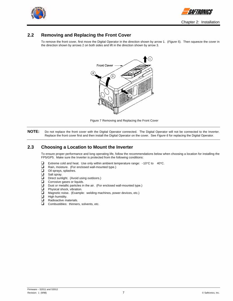
2.2 Removing and Replacing the Front CoverTo remove the front cover, first move the Digital Operator in the direction shown by arrow 1. (Figure 5). Then squeeze the cover inthe direction shown by arrows 2 on both sides and lift in the direction shown by arrow 3.
Figure 7 Removing and Replacing the Front Cover
NOTE: Do not replace the front cover with the Digital Operator connected. The Digital Operator will not be connected to the Inverter.Replace the front cover first and then install the Digital Operator on the cover. See Figure 6 for replacing the Digital Operator.
2.3 Choosing a Location to Mount the InverterTo ensure proper performance and long operating life, follow the recommendations below when choosing a location for installing theFP5/GP5. Make sure the Inverter is protected from the following conditions:
o Extreme cold and heat. Use only within ambient temperature range: −10°C to + 40°C.o Rain, moisture. (For enclosed wall-mounted type.)o Oil sprays, splashes.o Salt spray.o Direct sunlight. (Avoid using outdoors.)o Corrosive gases or liquids.o Dust or metallic particles in the air. (For enclosed wall-mounted type.)o Physical shock, vibration.o Magnetic noise. (Example: welding machines, power devices, etc.)o High humidity.o Radioactive materials.o Combustibles: thinners, solvents, etc.

Chapter 2: Installation
Firmware – S2011 and S3012
Revision: 1 (9/98) 8 © Saftronics, Inc.
2.4 ClearancesInstall the FP5/GP5 vertically and allow sufficient clearances for effective cooling as shown below.
Figure 8 Clearances
NOTE: 1. The clearances required at the top and bottom and both sides are common in open chassis type (IP00) and enclosedwall-mounted type (NEMA1/IP20).
2. Remove the top and bottom covers to use the open chassis type of 200V/400V 15kW or less.
3. When installing the models of 200V/400V 30kW or more equipped with eyebolts, extra spacing will be required on eitherside. For detailed dimensions, contact your Saftronics representative.
4. For the external dimensions and mounting dimensions, refer to Chapter 10 Dimensions.
5. Allowable intake air temperature to the Inverter:
• Open chassis type (IP00) : - 10°C to 45°C• Enclosed wall-mounted type : - 10°C to 40°C (NEMA 1/IP20)
6. Ensure sufficient space for the sections at the upper and lower parts marked with [ in order to permit the flow ofintake/exhaust air to/from the Inverter.

3Wiring
This chapter describes the main circuit wiring and the control circuit wiring of the FP5/GP5.
3.1 Connection Diagram....................................................... 10
3.2 Wiring the Main Circuit ................................................... 113.2.1 Wiring Precautions for Main Circuit Input .......................................................... 113.2.2 Wiring Precautions for Main Circuit Output........................................................ 123.2.3 Grounding ........................................................................................................... 123.2.4 Functions of Main Circuit Terminals................................................................... 133.2.5 Main Circuit Configuration .................................................................................. 153.2.6 Parts Required for Wiring ................................................................................... 17
3.3 Wiring the Control Circuit .............................................. 213.3.1 Functions of Control Circuit Terminals............................................................... 213.3.2 Wiring the Control Circuit Terminals .................................................................. 223.3.3 Precautions on Control Circuit Wiring ................................................................ 22
3.4 Wiring Inspection............................................................ 22

Chapter 3: Wiring
Firmware – S2011 and S3012
Revision: 1 (9/98) 10 © Saftronics, Inc.
WARNING• Only commence wiring after verifying that the power supply is turned OFF. Failure to observe this can result in an electrical shock or
fire.
• Wiring should be performed only by qualified personnel. Failure to observe this can result in an electrical shock or fire.
• When wiring the emergency stop circuit, check the wiring thoroughly before operation. Failure to observe this can result in personalinjury.
CAUTION• Verify that the Inverter rated voltage coincides with the AC power supply voltage. Failure to observe this can result in personal injury
or fire.
• Do not perform a withstand voltage test of the Inverter. It may cause semi-conductor elements to be damaged.
• To connect a Braking Resistor, Braking Resistor Unit or Braking Unit, follow the procedures described in Chapter 11. Improperconnection may cause fire.
• Tighten terminal screws to the specified tightening torque. Failure to observe this can result in a fire.
3.1 Connection DiagramBelow is a connection diagram of the main circuit and control circuit. Using the Digital Operator, the motor can be operated bywiring the main circuit only.
Figure 9 FP5/GP5 Connection Diagram
FP5/GP5

Chapter 3: Wiring
Firmware – S2011 and S3012
Revision: 1 (9/98) 11 © Saftronics, Inc.
2. Voltage or current input for the master frequency reference can be selected by constant n042. Voltage reference input ispreset at the factory (FV).
3. Control circuit Terminal FS of + 15V has a maximum output current capacity of 20 mA.
4. Multi-function analog output should be used for monitoring meters (e.g., output frequency meter) and should not be usedfor feedback control system.
3.2 Wiring the Main Circuit
WARNING• Make sure to ground the ground terminal ( ). (Ground resistance 200V class: 100Ω or less, 400V class: 10× or less.)
Failure to observe this can result in an electrical shock or a fire.
CAUTION• Never connect the AC main circuit power supply to output Terminals T1, T2, and T3 (U, V and W). The Inverter will be
damaged and invalidate the warranty.
3.2.1 Wiring Precautions for Main Circuit Input
§ Installation of Molded Case Circuit Breaker (MCCB)
Make sure to connect Molded Case Circuit Breakers (MCCB) or fuses between AC main circuit power supply andFP5/GP5 input Terminals L1, L2 and L3 (R, S, and T) to protect wiring.
§ Installation of Ground Fault Interrupter
When connecting a ground fault interrupter to input Terminals L1, L2 and L3 (R, S, and T), select one that is notaffected by high frequency.
Examples: NV series by Mitsubishi Electric Co., Ltd. (manufactured in or after 1988), EG, SG series by Fuji ElectricCo., Ltd. (manufactured in or after 1984).
§ Installation of Magnetic Contactor
Inverters can be used without a Magnetic Contactor (MC) installed at the power supply side. When the main circuitpower supply is shut OFF in the sequence, a MC can be used instead of a MCCB. However, when a MC is switchedOFF at the primary side, regenerative braking does not function and the motor coasts to a stop.
• The load can be operated/stopped by opening/closing the MC at the primary side. However, frequent switchingmay cause the Inverter to malfunction.
• When using a Braking Resistor Unit, use a sequencer to break power supply side on overload relay trip contact.If the Inverter malfunctions, the Braking Resistor Unit may be damaged.
§ Terminal Block Connection Sequence
Input power supply phases can be connected to any terminal regardless of the order of L1, L2 and L3 (R, S, and T)on the terminal block.
§ Installation of AC Reactor
When connecting an Inverter (200V/400V 15kW or less) to a large capacity power supply transformer (600k VA or
more), or when switching a phase advancing capacitor, excessive peak current flows in the input power supply
circuit, which may damage the converter section. In such cases, install a DC Reactor (optional) between Inverter ¾1 and ¾ 2 terminals or an AC Reactor (optional) on the input side. Installation of a reactor is effective for
improvement of power factor on the power supply side.
indicates twisted-pair shielded wires.indicates shielded wires andNOTE: 1.P

Chapter 3: Wiring
Firmware – S2011 and S3012
Revision: 1 (9/98) 12 © Saftronics, Inc.
§ Installation of Surge Suppressor
For inductive loads (magnetic contactors, magnetic relays, magnetic valves, solenoids, magnetic brakes, etc.)connected near the Inverter, use a surge suppressor simultaneously.
§ Prohibition of Installation of Phase Advancing Capacitor
If a Phase Advancing Capacitor or Surge Suppressor is connected in order to improve the power factor, it maybecome overheated and damaged by Inverter high harmonic components. Also, the Inverter may malfunctionbecause of overcurrent.
3.2.2 Wiring Precautions for Main Circuit Output
§ Connection of Terminal Block and Load
Connect output Terminals T1, T2, and T3 (U, V, and W) to motor lead wires T1, T2, and T3 (U, V, and W). Verifythat the motor rotates in the forward direction (CCW: counterclockwise when viewed from the motor load side) withthe forward RUN command. If the motor rotation is incorrect, exchange any two of output Terminals T1, T2, and T3(U, V, and W).
§ Strict Prohibition of Connection of Input Power Supply to Output Terminals
Never connect the input power supply to output Terminals T1, T2, and T3 (U, V, and W).
§ Strict Prohibition of Short Circuiting or Grounding of Output Circuit
Never touch the output circuit directly or put the output line in contact with the Inverter case. Otherwise, it may causean electrical shock or grounding. In addition, never short-circuit the output line.
§ Prohibition of Connection of Phase Advancing Capacitor or LC/RC Noise Filter
Never connect a Phase Advancing Capacitor or LC/RC noise filter to the output circuit.
§ Avoidance of Installation of Magnetic Starter
Do not connect a Magnetic Starter or MC to the output circuit. If the load is connected while the Inverter is running,the Inverter overcurrent protective circuit operates because of inrush current.
§ Installation of Thermal Overload Relay
An electronic overload protective function is incorporated into the Inverter. However, connect a Thermal OverloadRelay when driving several motors with one Inverter or when using a multi-pole motor. When using a ThermalOverload Relay, set Inverter constant n033 to 0 (motor overload protection selection: no protection). Additionally, forThermal Overload Relay at 50Hz, set the same rated current value as that described on the motor nameplate, or at60Hz 1.1 times larger than the rated current value described on the motor nameplate.
§ Wiring Distance between Inverter and Motor
If the total wiring distance between Inverter and motor is excessively long and the Inverter carrier frequency (maintransistor switching frequency) is high, harmonic leakage current from the cable will adversely affect the Inverter andperipheral devices.
If the wiring distance between Inverter and motor is long, reduce the Inverter carrier frequency as described below.Carrier frequency can be set by constant n050.
Table 2 Wiring Distance between Inverter and Motor
Wiring Distance between Inverter and Motor Up to 164ft(50m)
Up to 328ft(100m)
More than 328ft(100m)
Carrier Frequency(Set value of constant n050)
15kHz or less(6)
10kHz or less(4)
5kHz or less(2)
3.2.3 Grounding
• Ground resistance
• 200 V class: 100 Ω or less, 400 V class: 10 Ω or less
• Never ground the Inverter in common with welding machines, motors, or other large-current electrical equipment.Run all the ground wires in a conduit separate from wires for large-current electrical equipment.

Chapter 3: Wiring
Firmware – S2011 and S3012
Revision: 1 (9/98) 13 © Saftronics, Inc.
• Use the ground wires described in Tables 5 or 6 and keep the length as short as possible.
• When using several Inverter units side by side, ground the units as shown in Figure 10, (a) or (b). Do not loop theground wires as shown in (c).
Figure 10 Grounding of Three Inverter Units
3.2.4 Functions of Main Circuit Terminals
The following table outlines the functions of the main circuit terminals. Wire according to each terminal function.
Table 3 200 V Class Terminal Functions
ModelsFP5/GP5 23P7 to 27P5 2011 to 2015 2018 to 2075
Max Applicable MotorOutput 3.7 to 7.5 kW 11 to 15 kW 18.5 to 75 kW
L1 (R)L2 (S)L3 (T)
Main circuit input power supply
L11 (R1)L21 (S1)L31 (T1)
Main circuit inputpower supply
T1 (U)T2 (V)T3 (W)
Inverter output
B1
B2Braking Resistor Unit
Ö¾ 1
¾ 2
• DC Reactor (¾1 − ¾2)
• DC bus terminals (¾1 − ¾2
¾ 3
• DC Reactor (¾1 − ¾2)
• DC bus terminals (¾1 − ¾2
• Braking Unit (¾3 − Ö)
Ground terminal (Ground resistance: 100 Ω or less)

Chapter 3: Wiring
Firmware – S2011 and S3012
Revision: 1 (9/98) 14 © Saftronics, Inc.
Table 4 400 V Class Terminal Functions
ModelsFP5/GP5 40P4 to 4015 4018 to 4045 4055 to 4160 4185 to 4300
Max Applicable MotorOutput 0.4 to 15 kW 18.5 to 45 kW 55 to 160 kW 185 to 300 kW
L1 (R)L2 (S)L3 (T)
Main circuit inputpower supply
Main circuit inputpower supply
L11 (R1)L21 (S1)L31 (T1)
Main circuit input power supply
T1 (U)T2 (V)T3 (W)
Inverter output
B1B2
Braking Resistor Unit
Ö
¾ 1
• Braking Unit (¾ 3 − Ö)
¾ 2
• DC Reactor
(¾1 − ¾2
• DC bus terminals
(¾1 − Ö)
¾ 3 • Braking Unit (¾ 3 − Ö)
r (l 1)
s 200 (l 2 200)
s 400 (l 2 400)
Cooling fan power supply(Control power supplyr (l 1) − s 200 (l 2 200): 200 to 230 VAC inputr (l 1) − s 400 (l 2 400): 380 to 460 VAC input
Ground terminal (Ground resistance: 10Ω or less)

Chapter 3: Wiring
Firmware – S2011 and S3012
Revision: 1 (9/98) 15 © Saftronics, Inc.
3.2.5 Main Circuit Configuration
200V Class
FP5/GP523P7 to FP5/GP527P5 FP5/GP52011 to FP5/GP52015
FP5/GP52018 to FP5/GP52022 FP5/GP52030 to FP5/GP52075
= The wiring has been completed at the factory prior to shipping.
‡ When installing a DC Reactor (option) on models of 15kW or below, remove the short-circuit bar between
¾ 1 and ¾2 terminals and connect a DC Reactor with the terminals.
Chapter 3: Wiring
Firmware – S2011 and S3012
Revision: 1 (9/98) 16 © Saftronics, Inc.
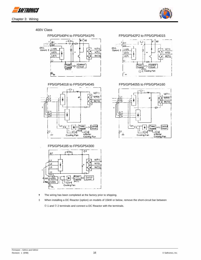
400V Class
FP5/GP540P4 to FP5/GP541P5 FP5/GP542P2 to FP5/GP54015
FP5/GP54018 to FP5/GP54045 FP5/GP54055 to FP5/GP54160
FP5/GP54185 to FP5/GP54300
= The wiring has been completed at the factory prior to shipping.
‡ When installing a DC Reactor (option) on models of 15kW or below, remove the short-circuit bar between
¾ 1 and ¾ 2 terminals and connect a DC Reactor with the terminals.

Chapter 3: Wiring
Firmware – S2011 and S3012
Revision: 1 (9/98) 17 © Saftronics, Inc.
3.2.6 Parts Required for Wiring
Select wires or Closed-Loop Connectors to be used for wiring from Tables 5, 6 and 7.
Table 5 200 V Class Wire Size
Wire Size =Circuit
ModelFP5/GP5 Terminal Symbol
TerminalScrew AWG mm2
Wire Type
L1, L2, L3, (R, S, T) Ö, ¾ 1, ¾ 2, B1, B2, T1, T2, T3(U, V, W)23P7 M4 10 5.5
L1, L2, L3, (R, S, T) Ö, ¾ 1, ¾ 2, B1, B2, T1, T2, T3(U, V, W)
8 825P5 M5
10-8 5.5 − 8
L1, L2, L3, (R, S, T) Ö, ¾ 1, ¾ 2, B1, B2, T1, T2, T3(U, V, W)
8 827P5 M5
10-8 5.5 − 8
L1, L2, L3, (R, S, T) Ö, ¾ 1, ¾ 2, ¾ 3, T1, T2, T3 (U,V, W)
4 222011 M6
8 8
L1, L2, L3, (R, S, T) Ö, ¾ 1, ¾ 2, ¾ 3, T1, T2, T3 (U,V, W)
M8 3 302015
M6 8 8
L1,L2, L3, (R, S, T) L11, L21, L31, (R1, S1, T1), T1,T2, (U, V, W) 3 30
2018 M86 14
L1,L2, L3, (R, S, T), L11, L21, L31, (R1, S1, T1), T1,T2, T3 (U, V, W) 2 38
2022 M86 14
L1,L2, L3, (R, S, T), L11, L21, L31, T1, T2, T3, (U, V,W) M10 4/0 100
2030M8 4 22
L1,L2, L3, (R, S, T), L11, L21, L31, T1, T2, T3, (U, V,W)
M10 1/0 x 2P 60 5 2P2037
M8 4 22
L1,L2, L3, (R, S, T), L11, L21, L31, T1, T2, T3, (U, V,W) M10 1/0 x 2P 60 5 2P
2045M8 4 22
L1,L2, L3, (R, S, T), L11, L21, L31, T1, T2, T3, (U, V,W) M10 1/0 x 2P 60 5 2P
2055M8 3 30
L1,L2, L3, (R, S, T), L11, L21, L31, T1, T2, T3, (U, V,W) M12 4/0 x 2P 100 5 2P
Main
2075M8 1 50
Power cable:600V vinylsheathed wireor equivalent
S1, S2, S3, S4, S5, S6, SC,FV, FI, FS, FC,AM, AC, M1, M2, MA, MB, MC
20-16
Stranded0.5 − 1.25
Solid0.5 − 1.25
ControlCommon toall models
G M3.5 20-14 0.5 − 2
Twistedshielded wire
= Where size is determined using 75°C temperature-rated copper wire.

Chapter 3: Wiring
Firmware – S2011 and S3012
Revision: 1 (9/98) 18 © Saftronics, Inc.
Table 6 400 V Class Wire Size
Wire Size =Circuit
ModelFP5/GP5 Terminal Symbol
TerminalScrew AWG mm2
Wire Type
L1, L2, L3, (R, S, T), Ö, ¾ 1, ¾ 2, B1, B2, T1, T2, T3(U, V, W)40P4 M4 2 − 5.5
L1, L2, L3 (R, S, T), Ö, ¾ 1, ¾ 2, B1, B2, T1, T2, T3(U, V, W)40P7 M4 2 − 5.5
L1, L2, L3, (R, S, T), Ö, ¾ 1, ¾ 2, B1, B2, T1, T2, T3(U, V, W)41P5 M4 2 − 5.5
L1, L2, L3 (R, S, T), Ö, ¾ 1, ¾ 2, B1, B2, T1, T2, T3(U, V, W)42P2 M4 2 − 5.5
L1, L2, L3 (R, S, T), Ö, ¾ 1, ¾ 2, B1, B2, T1, T2, T3(U, V, W)
14-10 2 − 5.543P7 M4
12-10 3.5 − 5.5
L1, L2, L3 (R, S, T), Ö, ¾ 1, ¾ 2, B1, B2, T1, T2, T3(U, V, W)44P0 M4 2 − 5.5
L1, L2, L3 (R, S, T), Ö, ¾ 1, ¾ 2, B1, B2, T1, T2, T3(U, V, W)45P5 M4 12-10 3.5 − 5.5
L1, L2, L3 (R, S, T), Ö, ¾ 1, ¾ 2, B1, B2, T1, T2, T3(U, V, W)47P5 M5 8-6 5.5
L1, L2, L3, (R, S, T), Ö, ¾ 1, ¾ 2, B1, B2, T1, T2, T3(U, V, W)
M5 8-6 8 − 144011
M6 8 8
L1, L2, L3 (R, S, T), Ö, ¾ 1, ¾ 2, B1, B2, T1, T2, T3(U, V, W)
M5 8-6 8 − 144015
M6 8 8
L1, L2, L3 (R, S, T), L11, L21, L31 (R1, S1, T11), T1,T2, T3 (U, V, W) M6 6 14
4018M8 8 8
L1, L2, L3 (R, S, T), L11, L21, L31 (R1, S1, T11), T1,T2, T3 (U, V, W) M6 4 22
4022M8 8 8
L1, L2, L3 (R, S, T), L11, L21, L31 (R1, S1, T11), T1,T2, T3 (U, V, W) 4 22
Main
4030 M88 8
Power cable:600V vinylsheathed wireor equivalent
= Where size is determined using 75°C temperature-rated copper wire.

Chapter 3: Wiring
Firmware – S2011 and S3012
Revision: 1 (9/98) 19 © Saftronics, Inc.
Table 6 400 V Class Wire Size (Continued)
Wire Size =Circuit
ModelFP5/GP5 Terminal Symbol
TerminalScrew AWG mm2
Wire Type
L1, L2, L3 (R, S, T), L11, L21, L31 (R1, S1, T11), T1,T2, T3 (U, V, W) 3 30
4037 M86 14
L1, L2, L3 (R, S, T), L11, L21, L31 (R1, S1, T11), T1,T2, T3 (U, V, W) 1 50
4045 M86 14
L1, L2, L3 (R, S, T), L11, L21, L31 (R1, S1, T11), T1,T2, T3 (U, V, W)
M10 4/0 1004055
M8 4 22
L1, L2, L3 (R, S, T), L11, L21, L31 (R1, S1, T11), T1,T2, T3 (U, V, W) M10 1/0 x 2P 60 x 2P
4075M8 4 22
L1, L2, L3 (R, S, T), L11, L21, L31 (R1, S1, T11), T1,T2, T3 (U, V, W)
M10 1/0 x 2P 60 x 2P4110
M8 3 30
L1, L2, L3 (R, S, T), L11, L21, L31 (R1, S1, T11), T1,T2, T3 (U, V, W)
M12 4/0 x 2P 100 x 2P4160
M8 1 50
L1, L2, L3 (R, S, T), Ö, ¾ 1, ¾ 3, T1, T2, T3 (U, V, W)M16
650MCMx 2P
325 x 2P
M8 1 504185
r (l1), s 200 (l2 200), s 400 (l2 400) M4 20-10 0.5 − 5.5
L1, L2, L3 (R, S, T), Ö, ¾ 1, ¾ 3, T1, T2, T3 (U, V, W) M16650MCM
x 2P325 x 2P
M8 1/0 604220
r (l1), s 200 (l2 200), s 400 (l2 400) M4 20-10 0.5 − 5.5
L1, L2, L3 (R, S, T), Ö, ¾ 1, ¾ 3, T1, T2, T3 (U, V, W) M16650MCM
x 2P325 x 2P
M8 1/0 60
Main
4300
r (l1), s 200 (l2 200), s 400 (l2 400) M4 20-10 0.5 − 5.5
Power cable:600V vinyl
sheathed wireor equivalent
S1, S2, S3, S4, S5, S6, SC,FV, FI, FS, FC,AM, AC, M1, M2, MA, MB, MC
20-16
Stranded0.5 − 1.25
Solid0.5 − 1.25
ControlCommon toall models
G M3.5 20-14 0.5 − 2
Twistedshielded wire
= Where size is determined using 75°C temperature-rated copper wire.

Chapter 3: Wiring
Firmware – S2011 and S3012
Revision: 1 (9/98) 20 © Saftronics, Inc.
Table 7 Closed-Loop Connectors
AWG Size Wire Size mm2 Terminal Screw Closed-Loop ConnectorsM3.5 1.25 − 3.5
20 0.5M4 1.25 − 4
M3.5 1.25 − 3.518 0.75
M4 1.25 − 4M3.5 1.25 − 3.5
16 1.25M4 1.25 − 4
M3.5 2 − 3.5M4 2 − 4M5 2 − 5M6 2 − 6
14 2
M8 2 − 8M4 5.5 − 4M5 5.5 − 5M6 5.5 − 6
12-10 3.5 / 5.5
M8 5.5 − 8M5 8 − 5M6 8 − 68 8M8 8 − 8M6 14 − 6
6 14M8 14 − 8M6 14 - 6
4 22M8 14 - 8
3-2 30 / 38 M8 38 − 8M8 60 − 8
1-1/0 50 / 60M10 60 − 10
3/0 80 80 − 104/0 100
M10100 − 10
4/0 100 100 − 12300MCM 150 150 − 12400MCM 200
M12200 − 12
M12 x 2 325 − 12650MCM 325
M16 325 − 16
NOTE: When determining wire size, consider voltage drop. Select a wire size so that voltage drop will be less than 2% of the normalrated voltage. Voltage drop is calculated by the following equation:
Phase-to-phase voltage drop (V) = /3 5 wire resistance (Ω/km) 5 wiring distance (m) 5 current (A) 5 10−3
Chapter 3: Wiring
Firmware – S2011 and S3012
Revision: 1 (9/98) 21 © Saftronics, Inc.
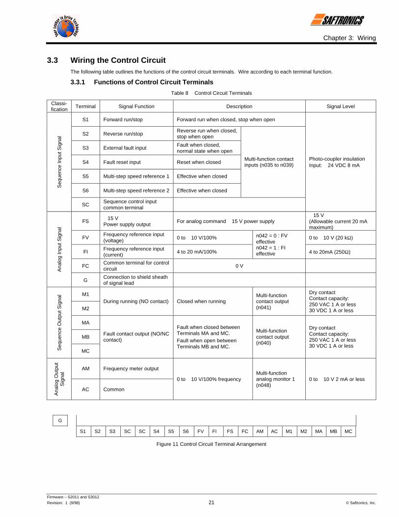
3.3 Wiring the Control CircuitThe following table outlines the functions of the control circuit terminals. Wire according to each terminal function.
3.3.1 Functions of Control Circuit Terminals
Table 8 Control Circuit Terminals
Classi-fication Terminal Signal Function Description Signal Level
S1 Forward run/stop Forward run when closed, stop when open
S2 Reverse run/stopReverse run when closed,stop when open
S3 External fault input Fault when closed,normal state when open
S4 Fault reset input Reset when closed
S5 Multi-step speed reference 1 Effective when closed
S6 Multi-step speed reference 2 Effective when closed
Multi-function contactinputs (n035 to n039)
Seq
uenc
e In
put S
igna
l
SCSequence control inputcommon terminal
Photo-coupler insulationInput: + 24 VDC 8 mA
FS + 15 VPower supply output
For analog command + 15 V power supply+ 15 V(Allowable current 20 mAmaximum)
FVFrequency reference input(voltage) 0 to + 10 V/100% 0 to + 10 V (20 kΩ)
FI Frequency reference input(current) 4 to 20 mA/100%
n042 = 0 : FVeffectiven042 = 1 : FIeffective 4 to 20mA (250Ω)
FCCommon terminal for controlcircuit 0 V
Ana
log
Inpu
t Sig
nal
GConnection to shield sheathof signal lead
M1
M2During running (NO contact) Closed when running
Multi-functioncontact output(n041)
Dry contactContact capacity:250 VAC 1 A or less30 VDC 1 A or less
MA
MB
Seq
uenc
e O
utpu
t Sig
nal
MC
Fault contact output (NO/NCcontact)
Fault when closed betweenTerminals MA and MC.Fault when open betweenTerminals MB and MC.
Multi-functioncontact output(n040)
Dry contactContact capacity:250 VAC 1 A or less30 VDC 1 A or less
AM Frequency meter output
Ana
log
Out
put
Sig
nal
AC Common
0 to + 10 V/100% frequencyMulti-functionanalog monitor 1(n048)
0 to + 10 V 2 mA or less
G
S1 S2 S3 SC SC S4 S5 S6 FV FI FS FC AM AC M1 M2 MA MB MC
Figure 11 Control Circuit Terminal Arrangement

Chapter 3: Wiring
Firmware – S2011 and S3012
Revision: 1 (9/98) 22 © Saftronics, Inc.
3.3.2 Wiring the Control Circuit Terminals
Insert the wire into the lower part of the terminal block and connect it tightly with a screwdriver. Wire sheath strip lengthmust be 7 mm (approximately ¼ inch).
3.3.3 Precautions on Control Circuit Wiring
• Separate control circuit wires from main circuit wires and other power cables to prevent erroneous operation causedby noise interference.
• Use twisted shielded or twisted-pair shielded wire for the control circuit line and connect the shielded sheath to theInverter Terminal G. See Figure 12.
Figure 12 Shielded Wire Termination
3.4 Wiring InspectionAfter completing installation and wiring, check for the following items. Never use control circuit megger check.
o Wiring is proper.
o Wire clippings or screws are not left in the unit.
o Screws are securely tightened.
o Bare wire in the terminal does not contact other terminals.

4Operation
This chapter describes the basic operation procedures of the FP5/GP5.
4.1 Operation Mode Selection......................................... 25
4.2 Test Run Checkpoints ............................................... 26
4.3 Setting the Line Voltage Using Jumper(For 400V Class 18.5kW and Above) ........................ 26
4.4 Test Run...................................................................... 274.4.1 Digital Operator Display at Power-Up....................................................... 274.4.2 Operation Check Points............................................................................. 2/4.4.3 Example of Basic Operation...................................................................... 28

Chapter 4: Operation
Firmware – S2011 and S3012
Revision: 1 (9/98) 24 © Saftronics, Inc.
WARNING• Only turn ON the input power supply after replacing the front cover. Do not remove the cover while current is flowing. Failure to
observe this can result in an electrical shock.
• When the retry function (n057) is selected, do not approach the Inverter or the load, since it may restart suddenly after beingstopped. (Construct machine system, so as to assure safety for personnel, even if the Inverter should restart.) Failure to observethis can result in personal injury.
• Since the stop button can be disabled by a function setting, install a separate emergency stop switch. Failure to observe this canresult in personal injury.
CAUTION• Never touch the heatsink or discharging resistor since the temperature is very high. Failure to observe this can result in harmful
burns to the body.
• Since it is easy to change operation speed from low to high speed, verify the safe working range of the motor and machine beforeoperation. Failure to observe this can result in personal injury and machine damage.
• Install a holding brake separately if necessary. Failure to observe this caution can result in personal injury.
• Do not change signals during operation. The machine or the Inverter may be damaged.
• All the constants of the Inverter have been preset at the factory. Do not change the settings unnecessarily. The Inverter may bedamaged. For supply voltage, follow Paragraph 4.3 of Chapter 4.

Chapter 4: Operation
Firmware – S2011 and S3012
Revision: 1 (9/98) 25 © Saftronics, Inc.
4.1 Operation Mode SelectionThe FP5/GP5 has two operation modes, LOCAL and REMOTE, as described in Table 9. These two modes can be selected bythe Digital Operator LOCAL/REMOTE key only while the operation is stopped. The selected Operation mode can be verified byobserving the Digital Operator SEQ and REF LED’s as shown below. The Operation mode is set to REMOTE (run by controlcircuit Terminals FV and FI frequency reference and RUN command from a control circuit terminal) prior to shipment. Multi-function contact inputs from control circuit Terminals S3 to S6 are enabled in both Operation modes LOCAL/REMOTE.
• LOCAL : Both frequency reference and RUN command are set by the Digital Operator. SEQ and REF LED’s go OFF.
• REMOTE : Master frequency reference and RUN command can be selected as described in Table 9.
Table 9 Reference Selection in REMOTE Mode (n002: Operation Method Selection)
Setting Operation Method Selection SEQLED
Reference Selection REFLED
0 Operation by RUN command from Digital Operator OFF Master frequency reference from Digital Operator OFF
1 Operation by RUN command from control circuitterminal
ON Master frequency reference from Digital Operator OFF
2 Operation by RUN command from Digital Operator OFF Master frequency reference from control circuitTerminals FV and FI ON
3 Operation by RUN command from control circuitterminal ON Master frequency reference from control circuit
Terminals FV and FI ON
4 Operation by RUN command from Digital Operator OFF Master frequency reference set by serialcommunication
ON
5 Operation by RUN command from control circuitterminal
ON Master frequency reference set by serialcommunication
ON
6 Operation by RUN command from serialcommunication ON Master frequency reference set by serial
communication ON
7 Operation by RUN command from serialcommunication ON Master frequency reference from Digital Operator OFF
8 Operation by RUN command from serialcommunication
ON Master frequency reference from control circuitTerminals FV and FI
ON

Chapter 4: Operation
Firmware – S2011 and S3012
Revision: 1 (9/98) 26 © Saftronics, Inc.
4.2 Test Run CheckpointsTo assure safety, prior to initial operation, disconnect the machine coupling so that the motor is isolated from the machine. Ifinitial operation must be performed while the motor is still coupled to the machine, use great care to avoid potentially hazardousconditions. Check the following items before a test run.
o Wiring and terminal connections are correct.
o No short-circuit caused by wire clippings.
o Screw-type terminals are securely tightened.
o Motor is securely mounted
o All items are correctly earthed (grounded).
4.3 Setting the Line Voltage Using Jumper (For 400V Class 18.5kW and Above)Set the line voltage jumper according to the main circuit power supply. (See Figure 13.) Insert the jumper at the appropriatelocation corresponding to the input line voltage. It has been preset at the factory to 440V.
Figure 13 Line Voltage Jumper (For 400V Class 18.5kW to 45kW)

Chapter 4: Operation
Firmware – S2011 and S3012
Revision: 1 (9/98) 27 © Saftronics, Inc.
4.4 Test Run4.4.1 Digital Operator Display at Power-up
When the system is ready for operation, turn ON the power supply. Verify that the Inverter powers up properly. If anyproblems are found, turn OFF the power supply immediately. The Digital Operator display illuminates as shown belowwhen turning the power supply ON.
Figure 14 Digital Operator Display at Power-Up

Chapter 4: Operation
Firmware – S2011 and S3012
Revision: 1 (9/98) 28 © Saftronics, Inc.
4.4.2 Operation Check Points
Check the following items during operation.
o Motor rotates smoothly.
o Motor rotates in the correct direction.
o Motor does not have abnormal vibration or noise.
o Acceleration and deceleration are smooth.
o Current matches the load flow.
o Status indicator LED’s and Digital Operator display are correct.
4.4.3 Example of Basic Operation.
§ Operation by Digital Operator
The diagram below shows a typical operation pattern using the Digital Operator.
Figure 15 Operation Sequence by Digital Operator
Table 10 Typical Operation by Digital Operator
Description Key Sequence Digital Operator Display LED Display¬ Power ON
• Display frequency reference value. 0.0 Fref
Operation Condition Setting REMOTE LED (SEQ. REF) OFF• Select LOCAL mode.
\ / Frequency Setting Change the value
• Change reference value. by pressing 15.0 Fref
/ \
• Write-in set value.15.0 Fref
• Select output frequency monitor display.0.0 Fout
® Forward Run• Forward run (15 Hz) 15.0 Fout
RUN LED ON

Chapter 4: Operation
Firmware – S2011 and S3012
Revision: 1 (9/98) 29 © Saftronics, Inc.
Table 10 Typical Operation by Digital Operator (continued)
¯ Frequency Reference Value Change(15 Hz to 60 Hz)
Fref• Select frequency reference value
display. Press 7 times15.0
• Change set value. Change the valueby pressing \ /
60.0 Fref
/ \
• Write-in set value.60.0 Fref
• Select output frequency monitor display.
60.0 Fref
° Reverse Run• Select reverse run.
fo F/R
Press 3 times
Switch to “rev” \ /by pressing
eu F/R
/ \
• Write-in set value. eu F/R
• Select output frequency monitor display.
60.0 Fout
Press 5 times
± Stop
• Decelerates to a stop. 0.0 Fout
RUN LED OFF STOP LED ON
§ Operation by Control Circuit Terminal Signal
The diagram below shows a typical operation pattern using the control circuit terminal signals.
Figure 16 Operation Sequence by Control Circuit Terminal Signal

Chapter 4: Operation
Firmware – S2011 and S3012
Revision: 1 (9/98) 30 © Saftronics, Inc.
Table 11 Typical Operation by Control Circuit Terminal Signal
Description Key Sequence Digital Operator Display LED Display¬ Power ON
• Display frequency reference value. 0.0 Fref
REMOTE mode is preset at the factory REMOTE LED (SEQ, REF) ON
Frequency Setting• Input frequency reference voltage 60.0 Fref
(current) by control circuit Terminal FV For reference voltage 10Vor FI and verify the input value by theDigital Operator.
Output Frequency Display
• Select output frequency monitor display. 0.0 Fout
® Forward Run• Close between control circuit Terminals 60.0 Fout
SI and SC to perform forward run. RUN LED ON
¯ Stop• Open between control circuit Terminals
SI and SC to stop operation. 0.0 Fout
STOP LED ON(RUN LED blinkingduring deceleration)

5Simple Data Setting
This chapter describes simple data setting.
5.1 Digital Operator Key Description................................... 32
5.2 LED Description .............................................................. 32

Chapter 5: Simple Data Setting
Firmware – S2011 and S3012
Revision: 1 (9/98) 32 © Saftronics, Inc.
5.1 Digital Operator Key Description
Mode Indicator LED’s (Remote Mode)Lights when selecting Input mode from the control circuit terminal orserial communication.SEQ: Lights when selecting RUN command from control circuit
terminal or serial communication.REF: Lights when selecting frequency reference from control
circuit Terminals FV and FI or serial communication.Display
Displays set values of each function or monitoring values such asfrequency and output current. (4 Digits)
Quick-Start LED’s
LED DescriptionSet/Read
DuringRun
Fref Frequency reference setting/monitoring EnableFout Output frequency monitor EnableIout Output current monitor Enable
kWout Output power monitor EnableF/R FWD/REV RUN command selection Enable
Montr Monitor selection EnableAccel Acceleration time EnableDecel Deceleration time EnableVmtr Motor rated voltage DisableV/F V/f pattern selection Disable
Fgain Frequency reference gain DisableFbias Frequency reference bias DisableFLA Motor rated current DisablePID PID selection Disable
kWsav Energy Saving selection DisablePRGM Constant number/data Disable
Enter KeyDisplays each constant set value. By pressing this key again, theset value is written in.
Number Change KeysChanges set values or constant numbers.∧ : Increment key∨ : Decrement key
Operation Command KeysOperation command keys operate the Inverter.*STOP/RESET : Red LED lights by pressing STOP.
(Resets operation at faults. Reset is disabledwhile a RUN command is ON.)
RUN : Red LED lights by pressing RUN.
Operation Mode Selection KeyThe Operation mode is alternated between REMOTE and LOCAL(Digital Operator).
Display Selection KeySelects the contents of Quick-Start LED’s. (See Page 33)
Figure 17 Digital Operator Key Description
5.2 LED DescriptionBy using the Quick-Start LED’s on the Digital Operator, simple operation of the Inverter is possible. Each Quick-Start LED isselected each time DSPL key is pressed. Following is a table describing Quick-Start LED selection.
(Example of model FP5/GP5)

Chapter 5: Simple Data Setting
Firmware – S2011 and S3012
Revision: 1 (9/98) 33 © Saftronics, Inc.
Table 12 LED Description
LEDDisplay Description Key Sequence Digital Operator Display Remarks
Power ON
Fref Frequency reference setting/monitoring 0.0
Fout Output frequency monitor 0.0
Iout Output current monitor 0.0
kWout Output power monitor 0.0
F/R FWD/REV RUN command selection Fo
Montr Monitor selection U – 01
Accel Acceleration time 10.0
Decel Deceleration time 10.0
(During run)
Press ENTER key todisplay the monitor value.
Vmtr Motor rated voltage 200.0
V/F V/f pattern selection 1
Fgain Frequency reference gain 100
Fbias Frequency reference bias 0
FLA Motor rated current 14.0
PID PID selection 0
kWsav Energy saving selection 0
Set/read is enabled onlyduring stop.
PRGM Constant number/data 002Press ENTER key to
display the data.

Chapter 5: Simple Data Setting
Firmware – S2011 and S3012
Revision: 1 (9/98) 34 © Saftronics, Inc.
NOTES:

6Programming Features
This chapter describes programming features.
6.1 Constant Set-Up and Initialization................................. 366.1.1 Constant Selection/Initialization (n001) ............................................................. 36
6.2 V/f Pattern Setting........................................................... 366.2.1 Preset V/f Pattern ............................................................................................... 376.2.2 Custom V/f Pattern ............................................................................................. 38
6.3 Setting Operation Conditions ........................................ 386.3.1 Reverse Run Prohibit (n006).............................................................................. 386.3.2 Multi-Step Speed Selection ................................................................................ 386.3.3 Operation at Low Speed..................................................................................... 396.3.4 Adjusting Frequency Setting Signal ................................................................... 406.3.5 Adjusting Frequency Upper and Lower Limits................................................... 416.3.6 Using Two Accel/Decel Times ........................................................................... 416.3.7 Automatic Restart after Momentary Power Loss (n051) ................................... 426.3.8 Soft-Start Characteristics (n023)........................................................................ 426.3.9 Torque Detection ................................................................................................ 436.3.10 Frequency Detection (n073)............................................................................... 446.3.11 Jump Frequencies (n058 to n060) ..................................................................... 446.3.12 Continuing Operation by Automatic Fault Reset (n056).................................... 456.3.13 Operating Coasting Motor without Trip .............................................................. 456.3.14 Using Frequency Meter of Ammeter (n048) ...................................................... 466.3.15 Calibrating Frequency Meter of Ammeter (n049) .............................................. 466.3.16 Reducing Motor Noise or Leakage Current (n050) ........................................... 47
6.4 Selecting Stopping Method............................................ 486.4.1 Selecting Stopping Method (n004)..................................................................... 486.4.2 Coast to Stop with Timer 1 (n004=2) ................................................................. 496.4.3 Applying DC Injection Braking Current (n064)................................................... 49
6.5 Building Interface Circuits with External Devices........ 506.5.1 Using Sequence Input Signals (n035 to n039).................................................. 506.5.2 Using Analog Input Signals (n042 to n045) ....................................................... 536.5.3 Using Output Signals (n040, n041).................................................................... 55
6.6 Setting Operation Conditions ........................................ 566.6.1 Torque Compensation Gain (n067) ................................................................... 56
6.7 Motor Protection ............................................................. 576.7.1 Motor Overload Detection .................................................................................. 57
6.8 PID Control ...................................................................... 586.8.1 Intended Value Setting ....................................................................................... 586.8.2 Detected Value Setting....................................................................................... 58
6.9 Energy Saving Control ................................................... 596.9.1 Energy Saving Gain K2 (n096) .......................................................................... 596.9.2 Energy Saving Tuning ........................................................................................ 59
6.10 MEMOBUS Control.......................................................... 606.10.1 Communication Specifications ........................................................................... 606.10.2 Data to be Sent/Received by Communication................................................... 60

Chapter 6: Programming Features
Firmware – S2011 and S3012
Revision: 1 (9/98) 36 © Saftronics, Inc.
6.1 Constant Set-up and Initialization6.1.1. Constant Selection/Initialization (n001)
The following table describes the data which can be set or read when n001 is selected.
Setting Constant that can be set Constant that can be read0
(Constant write disable) n001 n001 to n108
1(Factory setting)
n001 to n034 n001 to n108
2 n001 to n049 n001 to n1083 n001 to n108 n001 to n108
4, 5 Not used (disabled)8 Initialize: 2-wire sequence9 Initialize: 3-wire sequence [
[ Refer to Page 50.
6.2 V/f Pattern SettingV/f pattern can be set by constant n010.
Set value 0 to E: Preset V/f pattern can be selected.
F : Custom V/f pattern can be set.

Chapter 6: Programming Features
Firmware – S2011 and S3012
Revision: 1 (9/98) 37 © Saftronics, Inc.
6.2.1. Preset V/f Pattern
The following shows the preset V/f patterns. (The voltages are for 200V class. For 400V class, the value is twice that of200V class.)
Table 13 Preset V/f Pattern (n010 = 0 to E)
Specifications n010 V/f Pattern *1 Specifications n010 V/f Patterns *1
LowStartingTorque
8
50 Hz 0 50 Hz
HighStartingTorque
9
60 HzSaturation
1F
LowStartingTorque
A
60 Hz
50 HzSaturation 2
Hig
h S
tart
ing
Tor
que
*2
60 Hz
HighStartingTorque
BGen
eral
-Pur
pose
72 Hz 3 90 Hz C
VariableTorque 1 4
50 Hz
VariableTorque 2 5
120 Hz D
VariableTorque 3 6
Var
iabl
e T
orqu
e C
hara
cter
istic
s
60 Hz
VariableTorque 4 7
Hig
h S
peed
Ope
ratio
n
180 Hz E
∗ 1 Consider the following items as the conditions for selecting a V/f pattern. They must be suitable for:• The voltage and frequency characteristics of motor.• The maximum rotation speed of motor.
∗ 2 Select high starting torque only in the following conditions. Normally, this selection is not required.• The wiring distance is long (150 meters (492 feet) and above).• Voltage drop at startup is large.• AC Reactor is inserted in the input or output of the Inverter.• A motor smaller than the nominal output of the Inverter is used.
∗ 3 Voltages when the models of 200V, 55kW or above, or 400V, 55kW or above are selected.

Chapter 6: Programming Features
Firmware – S2011 and S3012
Revision: 1 (9/98) 38 © Saftronics, Inc.
6.2.2. Custom V/f Pattern
Set each pattern when using a special motor (high-speed motor, etc.) or when requiring special torque adjustment ofmachine.
Make sure to satisfy the followingconditions for setting of constantsn012 to n018.
n017 < n015 < n014 < n012
Figure 18 Custom V/f Pattern Setting
Constant No. Name Unit Setting Range Factory Setting
n012 Maximum output frequency 0.1 Hz 50.0 − 400.0 Hz 60.0 Hz
n013 Maximum voltage 0.1 V 0.1 − 255.0 V [ 200.0 V [
n014Maximum voltage outputfrequency (base frequency) 0.1 Hz 0.2 − 400.0 Hz 60.0 Hz
n015 Middle output frequency 0.1 Hz 0.1 −399.9 Hz 3.0 Hz
n016Middle output frequencyvoltage 0.1 V 0.1 − 255.0 V [ 15.0 V [
n017 Minimum output frequency 0.1 Hz 0.1 − 10.0 Hz 1.5 Hz
n018Minimum output frequencyvoltage 0.1 V 0.1 − 50.0 V [ 10.0 V [
∗ For 400 V class, the value is twice that of 200 V class.
Increasing the voltage of the V/f pattern increases motor torque, but an excessive increase may cause the following:
• Inverter malfunction because of motor overexcitation.
• Motor overheat or excessive vibration.
Increase voltage gradually while verifying the motor current.
6.3 Setting Operation Conditions6.3.1. Reverse Run Prohibit (n006)
“Reverse run disabled” setting does not accept a reverse RUN command from the control circuit terminal or DigitalOperator. This setting is used for applications where a reverse RUN command can cause problems.
Setting Description
0 Reverse run enabled
1 Reverse run disabled
6.3.2. Multi-Step Selection
By combining frequency reference and input terminal function selections, up to four steps of speed can be set.
Four step speed change
n002 = 1 (Operation mode selection)n025 = 30.0 Hzn026 = 40.0 Hzn027 = 50.0 Hzn028 = 60.0 Hzn038 = 9 (Multi-function contact input Terminal S5)n039 = 10 (Multi-function contact input Terminal S6)

Chapter 6: Programming Features
Firmware – S2011 and S3012
Revision: 1 (9/98) 39 © Saftronics, Inc.
Figure 19 Multi-Speed Selection – Control Circuit Terminals
Figure 20 Multi-Step Speed Operation Timing Diagram
6.3.3. Operating at Low Speed
Set jog frequency reference selection in multi-function contact input terminals (S2 to S6). Then input a FWD or REV RUNcommand. Operation is enabled at the jog frequency set in n029. When multi-step speed references 1 or 2 are inputsimultaneously with the jog frequency reference, the jog frequency reference has priority.
Name Constant No. Setting
Jog frequency reference n029 (Factory setting: 6.0 Hz)
Multi-function contact inputselection (S2 to S6) n035, n036, n037, n038, n039
Set to “11” (jog frequency selection)for any constant.
Chapter 6: Programming Features
Firmware – S2011 and S3012
Revision: 1 (9/98) 40 © Saftronics, Inc.
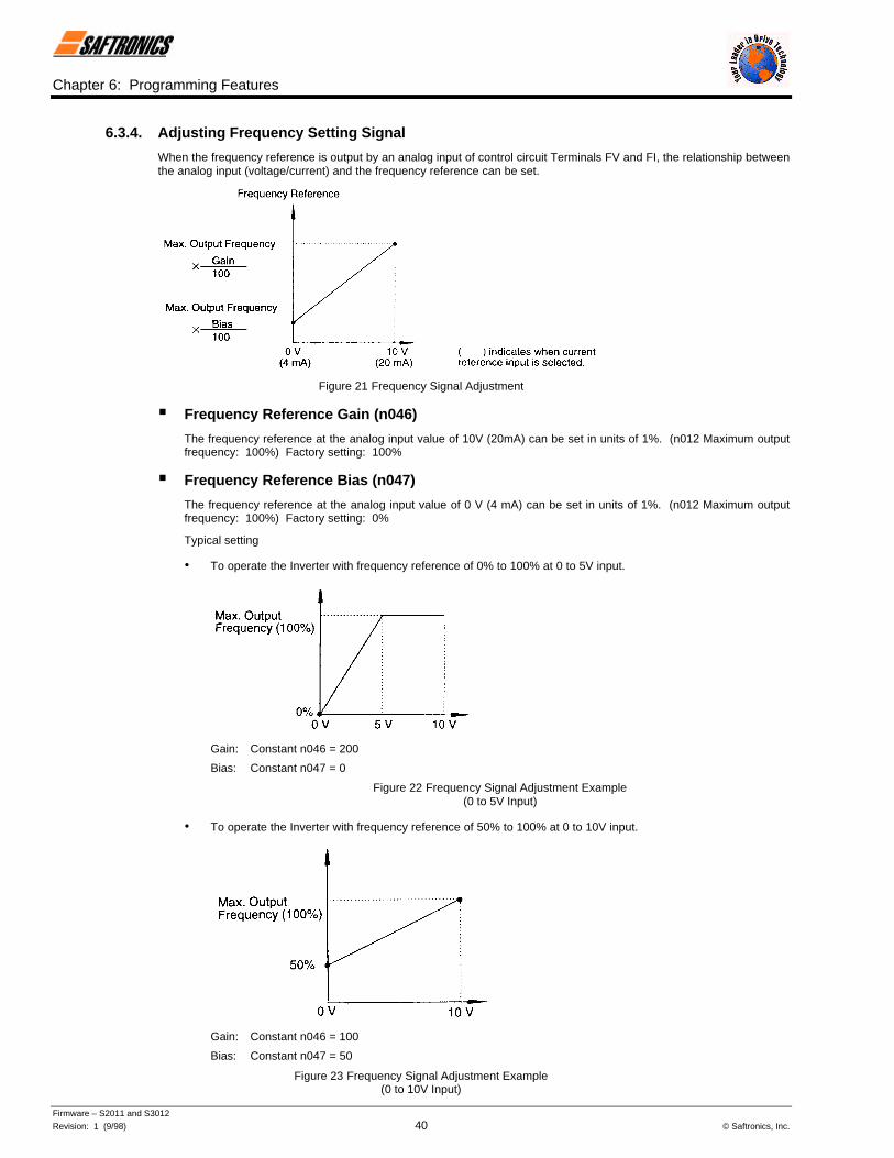
6.3.4. Adjusting Frequency Setting Signal
When the frequency reference is output by an analog input of control circuit Terminals FV and FI, the relationship betweenthe analog input (voltage/current) and the frequency reference can be set.
Figure 21 Frequency Signal Adjustment
§ Frequency Reference Gain (n046)
The frequency reference at the analog input value of 10V (20mA) can be set in units of 1%. (n012 Maximum outputfrequency: 100%) Factory setting: 100%
§ Frequency Reference Bias (n047)
The frequency reference at the analog input value of 0 V (4 mA) can be set in units of 1%. (n012 Maximum outputfrequency: 100%) Factory setting: 0%
Typical setting
• To operate the Inverter with frequency reference of 0% to 100% at 0 to 5V input.
Gain: Constant n046 = 200
Bias: Constant n047 = 0
Figure 22 Frequency Signal Adjustment Example(0 to 5V Input)
• To operate the Inverter with frequency reference of 50% to 100% at 0 to 10V input.
Gain: Constant n046 = 100
Bias: Constant n047 = 50
Figure 23 Frequency Signal Adjustment Example(0 to 10V Input)
Chapter 6: Programming Features
Firmware – S2011 and S3012
Revision: 1 (9/98) 41 © Saftronics, Inc.
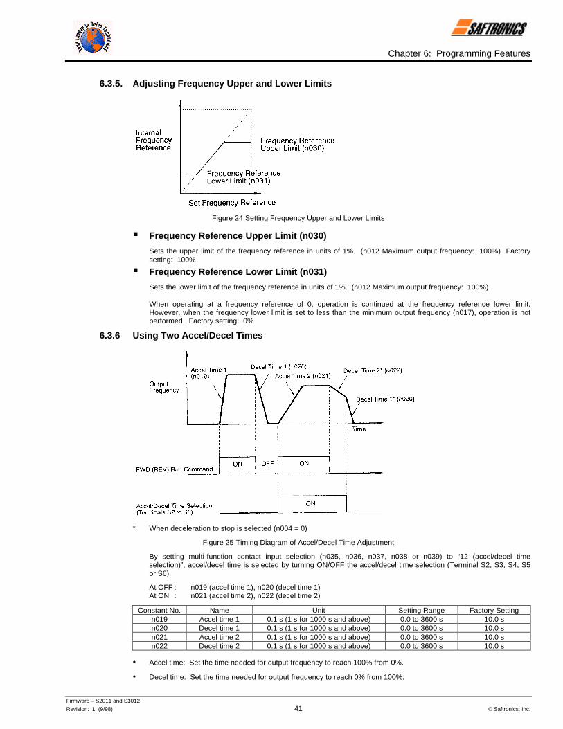
6.3.5. Adjusting Frequency Upper and Lower Limits
Figure 24 Setting Frequency Upper and Lower Limits
§ Frequency Reference Upper Limit (n030)
Sets the upper limit of the frequency reference in units of 1%. (n012 Maximum output frequency: 100%) Factorysetting: 100%
§ Frequency Reference Lower Limit (n031)
Sets the lower limit of the frequency reference in units of 1%. (n012 Maximum output frequency: 100%)
When operating at a frequency reference of 0, operation is continued at the frequency reference lower limit.However, when the frequency lower limit is set to less than the minimum output frequency (n017), operation is notperformed. Factory setting: 0%
6.3.6 Using Two Accel/Decel Times
* When deceleration to stop is selected (n004 = 0)
Figure 25 Timing Diagram of Accel/Decel Time Adjustment
By setting multi-function contact input selection (n035, n036, n037, n038 or n039) to “12 (accel/decel timeselection)”, accel/decel time is selected by turning ON/OFF the accel/decel time selection (Terminal S2, S3, S4, S5or S6).
At OFF : n019 (accel time 1), n020 (decel time 1)At ON : n021 (accel time 2), n022 (decel time 2)
Constant No. Name Unit Setting Range Factory Settingn019 Accel time 1 0.1 s (1 s for 1000 s and above) 0.0 to 3600 s 10.0 sn020 Decel time 1 0.1 s (1 s for 1000 s and above) 0.0 to 3600 s 10.0 sn021 Accel time 2 0.1 s (1 s for 1000 s and above) 0.0 to 3600 s 10.0 sn022 Decel time 2 0.1 s (1 s for 1000 s and above) 0.0 to 3600 s 10.0 s
• Accel time: Set the time needed for output frequency to reach 100% from 0%.
• Decel time: Set the time needed for output frequency to reach 0% from 100%.

Chapter 6: Programming Features
Firmware – S2011 and S3012
Revision: 1 (9/98) 42 © Saftronics, Inc.
6.3.7 Automatic Restart after Momentary Power Loss (n051)
When momentary power loss occurs, operation restarts automatically.
Setting Description
0 Not provided (Factory setting)
1 [ Continuous operation after power recovery within 2 seconds
2 =Continuous operation after power recovery within control logic time
(No fault output. Restarts only while control power supply is ON.)
∗ Hold the Operation command to continue operation after recovery from a momentary power loss.
= When 2 is selected, operation restarts if power supply voltage reaches its normal level. No fault signal is output.
6.3.8. Soft-Start Characteristics (n023)
To prevent shock during machine starting and/or stopping, accel/decel can be performed in S-curve pattern.
Setting S-curve Characteristic Time
0 S-curve not provided
1 0.2 s (Factory setting)
2 0.5 s
3 1.0 s
Note: S-curve characteristic time is the time from accel/decel rate 0 to a regular accel/decel rate determined by the setaccel/decel time.
Figure 26 S-Curve Characteristic Timing
The following time chart shows switching from FWD/REV at deceleration to stop.
Figure 27 S-Curve Characteristic FWD/REV Operation

Chapter 6: Programming Features
Firmware – S2011 and S3012
Revision: 1 (9/98) 43 © Saftronics, Inc.
6.3.9 Torque Detection
If an excessive load is applied to the machine, output current increase can be detected by output alarm signals at multi-function contact output Terminals MA, MB and M1.
To output an overtorque detection signal, set multi-function contact output selection n040 or n041 to “overtorquedetection” [Setting: 6 (NO contact) or 7 (NC contact)].
∗ Release width (hysteresis) during overtorque detection is 5% of the level of Inverter current.
Figure 28 Torque Characteristics
§ Overtorque Detection Function Selection (n074)
Setting Description
0 Detection disabled (Factory setting).
1 Detected during constant-speed running, and operation continues after detection.
2 Detected during running, and operation continues after operation.
3 Detected during constant-speed running, and Inverter output is shut OFF duringdetection.
4 Detected during running, and Inverter output is shut OFF during detection.
1. To detect overtorque during acceleration or deceleration, set to 2 or 4.
2. To continue the operation after overtorque detection, set to 1 or 2. During detection, the Digital Operatordisplays “OL3” alarm (blinking).
3. To halt the Inverter by a fault at overtorque detection, set to 3 or 4. At detection, the Digital Operator displays“OL3” fault (ON).
§ Overtorque Detection Level (n075)
Sets the overtorque detection current level in units of 1%. (Inverter rated current: 100%) Factory setting: 160%
§ Overtorque DetectionTime (n076)
If the time when motor current exceeds the overtorque detection level (n075) is longer than overtorque detection time(n076), the overtorque detection function operates. Factory setting: 0.1 seconds

Chapter 6: Programming Features
Firmware – S2011 and S3012
Revision: 1 (9/98) 44 © Saftronics, Inc.
6.3.10 Frequency Detection (n073)
Effective when multi-function contact output selections n040 or n041 are set to frequency detection (Setting: 4 or 5).Frequency detection turns ON when output frequency is higher or lower than the frequency detection level (n073).
§ Frequency Detection (Output Frequency << Frequency Detection Level)(Set n040 or n041 to 4.)
Figure 29 Frequency Detection Example(Fout ≤ Freq Detection Level)
§ Frequency Detection (Output Frequency >> Frequency Detection Level)(Set n040 or n041 to 5.)
Figure 30 Frequency Detection Example(Fout ≥ Freq Detection Level)
6.3.11 Jump Frequencies (n058 to n060)This function allows the prohibition or “jumping” of critical frequencies so that the motor can operate without resonancecaused by machine systems. This function is also used for dead band control. Setting the value to 0.0Hz disables thisfunction.
Set jump frequency 1 or 2 as follows:
n058 < n059 − n060
If this condition is not satisfied, the Inverter displays constant setting error OPE6.
Figure 31 Jump Frequencies

Chapter 6: Programming Features
Firmware – S2011 and S3012
Revision: 1 (9/98) 45 © Saftronics, Inc.
6.3.12 Continuing Operation by Automatic Fault Reset (n056)
Sets the Inverter to restart and reset fault detection after a fault occurs. The number of self-diagnosis and retry attemptscan be set in n056 up to 10. The Inverter will automatically restart after the following faults occur:
• OC (overcurrent)• OV (overvoltage)• UV1 (undervoltage PUV) (when n051 = 1 is selected)• GF (ground fault)• rr (regenerative transistor fault)
The number of retry attempts are cleared to 0 in the following cases:
• If no other fault occurs within 10 minutes after retry.• When the fault reset signal is ON after the fault is detected.• Power supply is turned OFF.
6.3.13 Operating Coasting Motor without Trip
To operate coasting motor without trip, use the Speed Search command or DC Injection Braking at start.
§ Speed Search Command
Restarts a coasting motor without stopping it. This function enables smooth switching between motor commercialpower supply operation and Inverter operation.
Set multi-function contact input selection (constants n035 to n039) to 15 (Search command from maximum outputfrequency) or 16 (Search command from set frequency).
Build a sequence so that FWD or REV RUN command is input at the same time or after the Search command. If theRUN command is input before the Search command, the Search command becomes disabled.
Following is a time chart at Search command input.
Figure 32 Search Command Input Timing Diagram

Chapter 6: Programming Features
Firmware – S2011 and S3012
Revision: 1 (9/98) 46 © Saftronics, Inc.
§ DC Injection Braking at Start (n064, n066)
Restarts a coasting motor after stopping it. Set the DC Injection Braking time at start in constant n066 in units of 0.1second. When constant n066 is set to 0, DC Injection Braking is not performed and acceleration starts from theminimum output frequency.
Set DC Injection Braking current in constant n064 in units of 1%. The Inverter rated current is 100%.
Figure 33 DC Injection Braking at Starting
6.3.14 Using Frequency Meter of Ammeter (n048)
Selects to output either output frequency or output current to analog output Terminals AM-AC for monitoring.
Setting Analog Monitor Output Item0 Output frequency (10 V/maximum frequency)1 Output current (10 V/Inverter rated current)2 Output power (10 V/Inverter rated voltage)3 DC bus voltage [10 V/400 V (200 V class), 10 V/800 V (400 V class)]
6.3.15 Calibrating Frequency Meter of Ammeter (n049)
Used to adjust analog output again.
Set the analog output voltage at 100% of output frequency.
Figure 34 Frequency Meter/Ammeter Calibration
Frequency meter displays 0 to 60Hz at 0 to 3V.
10 V X n049 Setting0.30
= 3 V
.
.
.Output frequency becomes 100% at this value.

Chapter 6: Programming Features
Firmware – S2011 and S3012
Revision: 1 (9/98) 47 © Saftronics, Inc.
6.3.16 Reducing Motor Noise or Leakage Current (n050)
Sets Inverter output transistor switching frequency (carrier frequency).
Setting Carrier Frequency (kHz) Metallic Noise fromMotor
Noise and CurrentLeakage
1 2.5 Higher Smaller
2 5.0
3 8.0
4 10.0
5 12.5
6 15.0 Not audible Larger
Figure 35 Custom Setting of Carrier Frequency Patterns

Chapter 6: Programming Features
Firmware – S2011 and S3012
Revision: 1 (9/98) 48 © Saftronics, Inc.
6.4 Selecting Stopping Method6.4.1. Selecting Stopping Method (n004)
Selects the stopping method suitable for the application.
Setting Description
0 Deceleration to stop (Factory setting)
1 Coast to stop
2 Coast to stop with timer 1
3 Coast to stop with timer 2
§ Deceleration to Stop (n004 = 0)
Figure 36 Stopping Method(Deceleration to Stop)
Upon removal of the FWD or REV RUN command, the motor decelerates at the deceleration rate determined by thetime set to decel time 1 (n020), and DC Injection Braking is applied immediately before stop. If the decel time isshort or the load inertia is large, an overvoltage (OV) fault may occur at deceleration. In this case, increase the deceltime or install an optional Braking Resistor (can be equipped with GP5).
Braking torque : Without Braking Resistor : Approximately 20% torque of motor ratingWith Braking Resistor : Approximately 150% torque of motor rating
§ Coast to Stop (n004 = 1)
Figure 37 Stopping Method(Coast to Stop)
Upon removal of the FWD or REV RUN command, the motor starts coasting.

Chapter 6: Programming Features
Firmware – S2011 and S3012
Revision: 1 (9/98) 49 © Saftronics, Inc.
6.4.2. Coast to Stop with Timer
§ Coast to Stop with Timer 1 (n004 = 2)
Example of accel/decel time 1 selection
Figure 38 Example of Stopping Method(Coast to Stop with Timer)
A RUN command is not accepted while the motor decelerates after a STOP command is given. However, if the timerequired for the motor to decelerate to a stop is shorter than the time set in constant n053 (minimum baseblock time),a RUN command is not accepted during the baseblock time.
§ Coast to Stop with Timer 2 (n004 = 3)
Example of accel/decel time 1 selection
Figure 39 Example of Stopping Method(Coast to Stop w/ Timer 2)
Operation is disabled while the motor decelerates after a STOP command is given. A RUN command is accepted,but operation does not start until the motor stops. However, if the deceleration time is shorter than the time set inn053 (minimum baseblock time), the Inverter does not operate during the baseblock time.
6.4.3. Applying DC Injection Braking
§ DC Injection Braking Current (N064)
Sets the DC Injection Braking current in units of 1%. (Inverter rated current: 100%)
§ DC Injection Braking Time at Stop (n065)
Sets the DC Injection Braking time at stopping in units of 0.1 second. When the setting is 0, DC Injection Braking isnot performed, but Inverter output is shut OFF when DC Injection Braking starts.

Chapter 6: Programming Features
Firmware – S2011 and S3012
Revision: 1 (9/98) 50 © Saftronics, Inc.
Figure 40 DC Injection Braking
When coast to stop is specified in stopping method selection (n004), DC Injection Braking at stop does not operate.
6.5 Building Interface Circuits with External Devices6.5.1. Using Sequence Input Signals (n035 to n039)
Multi-function contact input Terminal S2 to S6 functions can be changed when necessary by setting constants n035 ton039, respectively. Neither of these parameters can receive a setting common with the other.
• Terminal S2 function: Set to n035
• Terminal S3 function: Set to n036
• Terminal S4 function: Set to n037
• Terminal S5 function: Set to n038
• Terminal S6 function: Set to n039Table 14 Multi-Function Input Variables
Setting Name Description Page0 REV RUN command (2-wire sequence) Only constant n035 can be set. 51
1 FWD/REV RUN command(3-wire sequence) Only constant n035 can be set. 51
2 External fault (NO constant input)3 External fault (NC contact input)
Inverter stops at fault when external fault signal is input.Digital Operator displays EFo∗.
4 Fault reset Resets fault. Fault reset is disabled during RUN command input. 5 LOCAL/REMOTE selection 51
6 Serial communication/control circuitterminal selection 52
7 Fast stop Decelerates to stop by decel time 2 (n022) when fast stop is input.
8 Master frequency reference input levelselection
Master frequency reference input level (voltage input at open, currentinput at closed) can be selected.
9 Multi-step speed reference 110 Multi-step speed reference 2 38
11 Jog frequency selection 3912 Accel/decel time selection 4113 External baseblock (NO contact input)14 External baseblock (NC contact input)
Coasting signal. Motor starts coasting when the signal is input. DigitalOperator displays bb (blinking).
15 Search command from maximumfrequency
16 Search command from set frequencySpeed Search command signals. 45
17 Constant setting enable/disablePermission or prohibition of constant setting from the Digital Operator orserial communication (setting disabled at closed, enabled at open) can beselected.
18 PID integral value reset
19 PID Control disable 58
20 Timer function 52
21 OH3 (Inverter overheat alarm) When this signal is input, the Digital Operator displays OH3 (blinking).Inverter continues operation.
22 Analog reference sample/hold Analog frequency reference is sampled at closed and held at open. 5225 UP/DOWN command Only constant n039 can be set. 5326 Loop test Only constant n039 can be set. 53
∗2 to 6 are displayed in o corresponding to Terminals S2 to S6.Factory settings: n035=0, n036=2, n037=4, n038=9, n039=10

Chapter 6: Programming Features
Firmware – S2011 and S3012
Revision: 1 (9/98) 51 © Saftronics, Inc.
§ Terminal Function at 2-Wire Sequence Selection (Setting: 0)
Figure 41 Terminal Function at 2-Wire Sequence Selection
§ Terminal Function at 3-Wire Sequence Selection (Setting: 1)
Figure 42 Terminal Function at 2-Wire Sequence Selection
§ LOCAL/REMOTE Selection (Setting: 5)
Selects operation reference by the Digital Operator or by the control circuit terminal. LOCAL/REMOTE selection isavailable only during stop.
Open : Run according to the setting of Operation mode selection (n022).
Closed : Run by frequency reference and RUN command from the Digital Operator.
(Example) Set n002 to 3.Open : Run by frequency reference from control circuit Terminals FV, FI and RUN command from control
circuit Terminals S1, S2.
Closed : Run by frequency reference and RUN command from the Digital Operator.
§ Serial Communication/Control Circuit Terminal Selection (Setting: 6)
Selects operation reference by serial communication or by the control circuit terminal. This selection is available onlyduring stop.
Open : Run according to the setting of Operation mode selection (n022).
Closed : Run by frequency reference and RUN command from serial communication.
(Example) Set n002 to 3.Open : Run by frequency reference from control circuit Terminals FV, FI and RUN command from control
circuit Terminals S1, S2.
Closed : Run by frequency reference and RUN command from serial communication.

Chapter 6: Programming Features
Firmware – S2011 and S3012
Revision: 1 (9/98) 52 © Saftronics, Inc.
§ Timer Function (Setting: 20)
When the timer function input is longer than ON-delay timer (n077), the timer function output closes.
When the timer input is open for longer than OFF-delay timer (n078), the timer function output opens.
Figure 43 Timing Diagram of Timer Function
§ Analog Reference Sample/Hold Selection (Setting: 22)
If input terminal is closed for 100ms or more, the analog frequency reference is sampled; when it opens, the analogfrequency reference is held.
Note: t1, t3 : Reference is held at 100ms or more.
t2 : Reference is not held at less than 100ms.
Figure 44 Sample of Hold Selection (Analog Reference)
§ UP/DOWN Command (Setting: n039 = 25)
With the FWD or REV RUN command entered, accel/decel is enabled by inputting the UP or DOWN signals tocontrol circuit Terminals S5 and S6 without changing the frequency reference, so that operation can be performed atthe desired speed.
When UP/DOWN commands are specified by n039, any function set to n038 becomes disabled; Terminal S5becomes an input terminal for the UP command and Terminal S6 for the DOWN command.
Table 15 Timing Diagram of UP/DOWN Command Input
Control Circuit Terminal S5 (UP command) Closed Open Open Closed
Control Circuit Terminal S6 (DOWN command) Open Closed Open Closed
Operation Status Accel Decel Hold Hold

Chapter 6: Programming Features
Firmware – S2011 and S3012
Revision: 1 (9/98) 53 © Saftronics, Inc.
The following shows the time chart at UP/DOWN command input.
Figure 45 Timing Diagram of VP/Down Command Input
U = UP (accelerating) status
D = DOWN (decelerating) status
H = HOLD (constant Speed) status
U1 = UP status, clamping at upper limit speed
D1 = DOWN status, clamping at lower limit speed
NOTE: 1. When UP/DOWN command is selected, the upper limit speed is set regardless of frequency reference.Upper limit speed = Maximum output frequency (n012) 5 Frequency reference upper limit (n030)/100
2. Lower limit value is either frequency by Analog command from control circuit Terminals, FV, FI or frequency reference lowerlimit (n031) (whichever is larger).
3. When the FWD or REV RUN command is input, operation starts at the lower limit speed without an UP/DOWN command.
4. If the jog frequency selection command is input while running by the UP/DOWN command, the jog command has priority.
§ Loop Test (Setting: 26)
Checks operation in the serial I/F circuit. If a fault occurs, the Digital Operator displays CE.
Procedure
1. Set the multi-function contact input selection (n039) after turning ON the Inverter power supply, and then turnOFF the Inverter power supply.
2. Short-circuit Terminals S6 and SC, connector 2CN pins 1 and 2. (Do not short-circuit when connectingcommunication interface card SI-K2/P.)
3. Loop test is started by turning ON the Inverter power supply.
The Digital Operator displays the frequency reference after the loop test is completed satisfactorily.
6.5.2. Using Analog Input Signals (n042 to n045)
§ Master Analog Input Selection (n042)
To input the master frequency reference from the control circuit terminal, select voltage reference Terminal FV orcurrent reference Terminal FI by setting constant n042.
SettingMaster Frequency
Reference Terminal Input Level
0 FV 0 to 10 V input1 FI 4 to 20 mA input

Chapter 6: Programming Features
Firmware – S2011 and S3012
Revision: 1 (9/98) 54 © Saftronics, Inc.
§ Auxiliary Analog Input Selection (n043)
To change the control circuit Terminal FI input level, set constant n043.
Setting FI Terminal Input Level
0 0 to 10 V input
1 4 to 20 mA input
NOTE: To set constant n043 to 0, cut jumper J1 on the Inverter control PC board.
§ Frequency Reference Retention (n044)
Effective when UP/DOWN or Sample/Hold commands are selected for multi-function contact inputs. To retain theheld frequency reference at power OFF, set constant n044 to 0.
Setting Description
0 Hold reference retained in frequency reference 1 (constant n025)
1 Not retained
§ Operation Method for Frequency Reference Loss Detection (no45)
Select operation in case the frequency reference from control circuit terminal decreases rapidly.
Setting Description
0 No detection
1 Continue to run at 80% of Fmax.
(Operation when 1 is selected)
If frequency reference decreases by 90% within 400ms, operation is performed at 80% of the reference reachedbefore decreasing.

Chapter 6: Programming Features
Firmware – S2011 and S3012
Revision: 1 (9/98) 55 © Saftronics, Inc.
6.5.3. Using Output Signals (n040, n041)
Multi-function contact output Terminals MA, MB and M1 functions can be changed when necessary by setting constantsn040 and n041.
• Terminal MA and MB functions: Set to n040.
• Terminal M1 function: Set to n041.
Table 16 Multi-Function Output Variables
Setting Name Description Page
0 Fault Closed when Inverter fault occurs.
1 During running Closed when either FWD or REV RUN command is input or when the Inverter outputsvoltage.
2 Frequency agree 56
3 Desired frequencyagree 56
4 Frequency detection 1 44
5 Frequency detection 2 44
6 Overtorque detection(NO contact) 43
7 Overtorque detection(NC contact) 43
8 During baseblock Closed when Inverter output shuts OFF.
9 Operation mode Closed when RUN command or frequency reference from Digital Operator is selected.
10 Inverter operationready Closed when no Inverter fault does not occur and the Inverter can be operated.
11 Timer function 52
12 Automatic restart Closed during fault retry operation.
13 OL pre-alarmOutputs an alarm before Inverter and motor overload protection are enabled. Pre-alarm levelis 150% for 48 seconds for the Inverter and more than 80% of the overload protection time forthe motor.
14 Frequency referenceloss
Outputs a contact when detecting a rapid decrease in the frequency reference. A rapiddecrease in the frequency reference means that the reference value is reduced more than90% within 400ms when the reference is input to control circuit terminal.
15 Output from serialcommunication
Activates contact output independently from Inverter operation by a command from serialcommunications (MEMOBUS).
16 PID feedback lossDetects a rapid decrease in feedback and outputs a contact when the PID Control mode isset. Detects when the feedback value decreases less than the detection level (n093) forlonger than the feedback loss detection delay time (n094); the Inverter continues operation.
17 OH1 alarm Closed during heatsink overtemperature (Digital Operator displays OH1” blinking).
Factory settings: n040=0, n041=1

Chapter 6: Programming Features
Firmware – S2011 and S3012
Revision: 1 (9/98) 56 © Saftronics, Inc.
§ Setting Example of Frequency Agree Signal (Setting: 2)
Figure 46 Example of Frequency Agree Signal
§ Setting Example of Desired Frequency Agree Signal (Setting: 3)
Figure 47 Example of Desired Frequency Agree Signal
6.6 Adjusting Motor Torque6.6.1. Torque Compensation Gain (n067)
Motor torque requirement changes according to load conditions. Full-range automatic torque boost adjusts voltage of V/fpattern according to the requirement. The FP5/GP5 automatically adjusts the voltage during constant-speed operation aswell as during acceleration. The required torque is calculated by the Inverter.
Output voltage ∝ Torque compensation gain (n067) 5 Required torque
• Operation
Figure 48 Torque Characteristics
Normally, no adjustment is necessary for torque compensation gain (n067 factory setting: 1.0). When the wiring distancebetween the Inverter and the motor is long, or when the motor generates vibration, change the torque compensation gain.
Increasing torque compensation gain increases motor torque, but an excessive increase may cause the following:
• Inverter malfunctions because of motor overexcitation.
• Motor overheat or excessive vibration.
Increase torque compensation gain gradually while verifying the motor current.

Chapter 6: Programming Features
Firmware – S2011 and S3012
Revision: 1 (9/98) 57 © Saftronics, Inc.
6.7 Motor Protection6.7.1. Motor Overload Detection
The Inverter protects against motor overload with a built-in electronic Thermal Overload Relay.
§ Motor Rated Current (n032)Set to the rated current value shown on the motor nameplate.
§ Motor Overload Protection Selection (n033)Setting Electronic Thermal Characteristics
0 No protection1 Standard motor (time constant 8 minutes) (Factory setting)2 Standard motor (time constant 5 minutes)3 Inverter motor (time constant 8 minutes)4 Inverter motor (time constant 5 minutes)
The electronic Thermal Overload Relay function monitors motor temperature, based on Inverter output current andtime, to protect the motor from overheating. When electronic Thermal Overload Relay is enabled, an OL1 erroroccurs, shutting OFF the Inverter output and preventing excessive overheating in the motor.
When operating with one Inverter connected to one motor, an external Thermal Overload Relay is not needed.When operating several motors with one Inverter, install a Thermal Overload Relay on each motor. In this case, setconstant n033 to 0.
§ Standard Motor and Inverter MotorInduction motors are classified as standard motors or Inverter motors, based on their cooling capabilities. Therefore,the motor overload function operates differently between these two motor types.
Table 17 Overload Curves
Cooling Effect Torque Characteristics Electronic ThermalOverload
Sta
ndar
d M
otor
Effective when operatedat 50/60 Hz fromcommercial power supply.
Operation Frequency (Hz)Base Frequency 60 Hz
(V/f for 60 Hz, 220 V Input Voltage)For low speed operation, torque must belimited in order to stop motor temperature rise.
OL1 error (motor overloadprotection) occurs whencontinuously operated at50/60 Hz or less at 100%load.
Inve
rter
Mot
or
Effective even whenoperated at low speed(approximately 6 Hz).
Operation Frequency (Hz)Base Frequency 60 Hz
(V/f for 60 Hz, 220 V Input Voltage)Use an inverter motor for continuousoperation at low speed.
Electronic ThermalOverload Relay protectionnot enabled even whencontinuously operated at50/60 Hz or less at 100%load.

Chapter 6: Programming Features
Firmware – S2011 and S3012
Revision: 1 (9/98) 58 © Saftronics, Inc.
6.8 PID ControlTo enable PID Control, set PID selection (n084) from 1 to 3.
Setting Description
0 PID disabled
1 PID enabled (Deviation I D-controlled.)
2 PID with feed forward (Feedback value is D-controlled.)
3 PID with feed forward (Feedback is reversed characteristics.)
Then select the PID Control intended value or detected value settings as follows.
6.8.1. Intended Value SettingFor setting the intended value, control circuit Terminal FV voltage signal (0 to 10 V) or multi-step speed constants n025 ton029 can be used.
Control circuit Terminal FV voltage signal: Set Operation mode selection (n002) to 2 or 3.
Multi-step speed constants (n025 to n029): Set Operation mode selection (n002) to 0 or 1. (Combination of multi-stepspeed reference and jog frequency reference.)
6.8.2. Detected Value SettingFor setting the detected value, control circuit Terminal FI current signal (4 to 20mA) or voltage signal (0 to 10 V) can beused.
Control circuit Terminal FI current signal: Set auxiliary analog input selection (n043) to 1.
Control circuit Terminal FI voltage signal: Set auxiliary analog input selection (n043) to 0. (Cut jumper J1 on the controlPC board.)
The following shows the block diagram of PID Control.
Figure 49 PID Control Block Diagram
NOTE: 1. Value I is reset to 0 in the following cases:
• When operation stops.
• When the integral value reset signal is input by multi-function contact input selection. (Any of constants n035 to n039 areset to 18.
2. The upper limit of value I can be set by constant n090. Increase the value of constant n090 to upgrade control capability byintegration. If the control system vibrates and it cannot be stopped by adjusting the integral time or output lag filter time,etc., decrease the setting of constant n090.
3. PID Control can be canceled by a multi-function contact input signal. By setting any of constants n035 to n039 to 19, and byclosing the contact during running, PID Control is disabled and the intended value signal itself is used as a frequencyreference signal.

Chapter 6: Programming Features
Firmware – S2011 and S3012
Revision: 1 (9/98) 59 © Saftronics, Inc.
6.9 Energy Saving ControlTo enable Energy Saving Control, set energy saving selection (n095) to 1.
Setting Description
0 Energy saving is disabled
1 Energy saving is enabled
Since the constants used in the Energy Saving Control mode have been preset at the factory to the optimum values prior toshipment, it is not necessary to adjust them under normal operation. If your motor characteristics differ greatly from those ofSaftronics standard motors, refer to the following description to change the constants.
6.9.1. Energy Saving Control Mode
§ Energy Saving Gain K2 (n096)
Use this energy saving gain when running in the Energy Saving Control mode to calculate the voltage at which motorefficiency will be greatest, and set it as the output voltage reference. This value is preset at the factory to theSaftronics standard motor value prior to shipment. As the energy saving gain increases, output voltage increasesalso.
§ Energy Saving Voltage Lower Limit (n097, n098)
Sets the output voltage lower limit. If the voltage reference value calculated in the Energy Saving Control mode issmaller than the specified lower limit, this lower limit value is output as the voltage reference value. The lower limitvalue is set in order to prevent stalling at light loads. Set voltage limits at 6Hz and 60Hz; a value obtained by linearinterpolation should be set to any limit values other than at 6Hz or 60Hz. Setting is made as a percentage of motorrated voltage.
∗ For 400 V class, the value is twice that of 200 V class.
Figure 50 Energy Saving Voltage Lower Limit
6.9.2. Energy Saving Tuning
In the Energy Saving Control mode, the optimum voltage is calculated according to load power, and the voltage issupplied to the load. However, the set constant may vary due to temperature variations or using other manufacturers’motors, therefore, the optimum voltage may not be supplied in some cases. Automatic tuning controls voltage so thathighly efficient operation is maintained.
§ Voltage Limit of Tuning (n100)
Limits the range to control voltage by tuning. Setting is made in a percentage of motor rated voltage. By setting thisvalue to 0, turning is disabled.

Chapter 6: Programming Features
Firmware – S2011 and S3012
Revision: 1 (9/98) 60 © Saftronics, Inc.
§ Step Voltage of Tuning (n100, n101)
Sets voltage variation width of one tuning cycle. Setting is made in a percentage of motor rated voltage. Byincreasing this value, the rotating speed variation becomes larger. This voltage variation width is set when startingtuning voltage is 100% and motor rated voltage is 5%. Values obtained by linear interpolation are set to any voltagevalues other than these values.
Figure 51 Energy Saving Voltage Variation Width
6.10 MEMOBUS ControlFP5/GP5 can perform serial transmission by using a Programmable Controller (PLC) and MEMOBUS communication. MEMOBUSis composed of one master PLC and 1 to 31 (maximum) slave units (FP5/GP5). In signal transmission (serial transmission)between the master and slaves, the master always starts transmission and the slaves respond to it.
The master performs signal transmission with one slave at a time. Therefore, address numbers are assigned to each slave inadvance and the master specifies a number to perform signal transmission. The slave which receives the command from themaster executes the function and returns the response to the master.
6.10.1. Communication Specifications
• Interface : RS-485 (Communication interface card SI-K2/P must be mounted.)
• Synchronization : Asynchronous
• Transmission parameter : • Baud rate : Selectable from 2400, 4800, 9600 BPS (Constant n107)
• Data length : Fixed to 8 bits
• Parity : Parity / no-parity, even / odd selectable (Constant n108)
• Stop bit : Fixed to 1 bit
• Protocol : In accordance with MEMOBUS
• Maximum number of unitsto be connected
: 31 units (when RS-485 is used)
6.10.2. Data to be Sent/Received by Communication
Data to be sent/received by communication are RUN commands, frequency reference, fault contents, Inverter status andconstant setting/reading.
§ Operation Mode Selection (n002)
Select the RUN command and frequency reference input method in constant n002. To provide a RUN commandand frequency reference by communication, set this constant to settings 4 to 8. Also, without regard to this selection,monitoring of running status, constant setting/reading, fault reset and multi-function input command from the PLC areenabled. The multi-function input command becomes OR with the command input from control circuit Terminals S2to S6.

Chapter 6: Programming Features
Firmware – S2011 and S3012
Revision: 1 (9/98) 61 © Saftronics, Inc.
§ MEMOBUS Frequency Reference Unit (n105)
The frequency reference units from the PLC and in the frequency reference and output frequency monitors (bycommunication) are selected. The output frequency resolution of the FP5/GP5 is 0.1 Hz. Even if the frequencyreference unit is changed to 0.01 Hz in constant n105, the value in the hundredth digit of 0.01 Hz of the receivedfrequency reference is rounded off internally. When 30000/100% in units of 0.1% is selected, the value is roundedoff in the same way.
§ MEMOBUS Slave Address (n106)
The slave address number is set. It is necessary to set the address number so that it will not overlap with theaddress number of another slave connected on the same transmission line.
NOTE: To change the values set in constants n106 to n108 and enable new settings, it is necessary to turn OFF the power supply, andthen turn it ON again.

Chapter 6: Programming Features
Firmware – S2011 and S3012
Revision: 1 (9/98) 62 © Saftronics, Inc.
NOTES:

7Maintenance and Inspection
This chapter describes basic maintenance and inspection procedures for the FP5/GP5.
7.1 Periodic Inspector........................................................... 64
7.2 Parts Replacement Schedule (Guidelines) ................... 64

Chapter 7: Maintenance and Inspection
Firmware – S2011 and S3012
Revision: 1 (9/98) 64 © Saftronics, Inc.
WARNING• Never touch high-voltage terminals in the Inverter. Failure to observe this can result in an electrical shock.
• Replace all protective covers before powering up the Inverter. To remove the cover, make sure to shut OFF the Molded Case CircuitBreaker. Failure to observe this can result in an electrical shock.
• Perform maintenance or inspection only after verifying that the CHARGE LED goes OFF, after the main circuit power supply is turnedOFF. The capacitors are still charged and can be dangerous.
• Only authorized personnel should be permitted to perform maintenance, inspections or parts replacements. (Remove all metalobjects (watches, bracelets, etc.) before operation. Use tools which are insulated against electrical shock.) Failure to observe thiscan result in an electrical shock.
CAUTION• The control PC board employs CMOS ICs. Do not touch the CMOS elements. They are easily damaged by static electricity.
• Do not connect or disconnect wires or connectors while power is applied to the circuit. Failure to observe this can result in personalinjury.
7.1 Periodic InspectionThe FP5/GP5 will function longer if it is kept clean, cool and dry, while observing the precautions listed in 2.3 Choosing a Location toMount the Inverter. Check for tightness of electrical connections, discoloration or other signs of overheating or aging. Use Table 18as your inspection guide. Before servicing, turn OFF AC main circuit power and be sure that the CHARGE LED is OFF.
Table 18 Periodic Inspection
Component Check Corrective Action
Loose screws. Tighten.External Terminals,Unit Mounting Bolts,
Connectors, etc. Loose connectors. Tighten.
Heatsink Build-up of dust and dirt.Blow with dry compressed air of 39.2 5 104 to 58.8 5 104 Pa (4to 6kg⋅cm2) pressure.
Printed Circuit BoardAccumulation of conductive dust oroil.
Blow with dry compressed air of 39.2 5 104 to 58.8 5 104 Pa (4to 6kg⋅cm2) pressure. If dust and oil cannot be removed,replace the board.
Cooling FanFor abnormal noise and vibration.Whether the cumulative operationtime exceeds 20,000 hours or not.
Replace the cooling fan.
Power Elements Accumulation of dust and dirt.Blow with dry compressed air of 39.2 5 104 to 58.8 5 104 Pa (4to 6kg⋅cm2) pressure.
Smoothing Capacitor Discoloration or odor. Replace the capacitor or Inverter unit.
7.2 Parts Replacement Schedule (Guidelines)Replace the following parts periodically, for a long, safe, trouble free working life of FP5/GP5.
Table 19 Parts Replacement Schedule
Parts Interval (Approximately) Remarks
Cooling Fan 2 to 3 years Replace with new one.
Smoothing Capacitor 5 years Replace with new one. (Decided after inspection.)
Breakers or Relays Decided after inspection.
Fuse 10 years Replace with new one.
Aluminum Electrolytic Capacitor on PC Board 5 years Replace with new one. (Decided after inspection.)
NOTE: Operating conditions are as follows:
Ambient temperature : 30°C yearly average
Load factor : 80% or below
Operation rate : 12 hours or below/day

8Troubleshooting
This chapter describes the Inverter fault display and the fault contents caused by motor/machinemalfunctions and the corrective actions to be taken.
8.1 Fault Diagnosis and Corrective Actions ....................... 66
8.2 Alarm Display and Explanation ..................................... 69
8.3 Motor Faults and Corrective Actions ............................ 70

Chapter 8: Troubleshooting
Firmware – S2011 and S3012
Revision: 1 (9/98) 66 © Saftronics, Inc.
8.1 Fault Diagnosis and Corrective Actions
§ When the FP5/GP5 detects a fault, the fault is displayed on the Digital Operator and activates the fault contact output and themotor coasts to a stop. Check the cause in the table below and take the corrective actions.
§ If the inspections or corrective actions described cannot solve the problem, contact your Saftronics representative immediately.
§ To restart, turn ON the reset input signal or press the RESET key or shut OFF the main circuit power supply once, to reset thestop status.
§ To change the setting of a constant during fault display, first press the DSPL key to call up the monitor display. Then pressDSPL and ENTER keys simultaneously to enter PRGM mode.
NOTE: When a FWD or REV RUN command is input, the Inverter does not receive a fault reset signal. Make sure to reset after turningOFF the FWD or REV RUN command.

Chapter 8: Troubleshooting
Firmware – S2011 and S3012
Revision: 1 (9/98) 67 © Saftronics, Inc.
Table 20 Fault Diagnosis and Corrective Actions
FaultDisplay Description Details Corrective Action
U 1Main circuitundervoltage (PUV)
Undervoltage in the DC main circuit duringrunning.Detection level:200 V class: Approximately 190 V or less.400 V class: Approximately 380 V or less.
U 2Control circuitundervoltage (CUV)
Undervoltage in the control circuit duringrunning.
U 3 MC fault The pre-charge contactor opened duringrunning.
• Check the power supply wiring.• Correct the line voltage.
O c Overcurrent (OC)The Inverter output current exceeded the OClevel.
• Check the motor coil resistance.• Extend the accel/decel time.• Check the motor insulation.• Multi-meter check.
O Overvoltage (OV)
The main circuit DC voltage exceeded the OVlevel.Detection level:200 V class: Approximately 400 V400 V class: Approximately 800 V
Extend the deceleration time, add brakingcircuit.
G FGrounding (GF)Earth fault)
Inverter output grounding current exceeded50% of Inverter rated current.
• Check that motor insulation has notdeteriorated.
• Check that connection between Inverter andmotor is not damaged.
P U F Main circuit fault (PUF) • The direct current circuit fuse is blown.• The output transistors were damaged.
Check for damaged transistor, load side shortcircuit, grounding, etc.
∗ O H 1Heatsink overheat(OH1)
The transistor heatsink temperature exceededthe allowable value.(Fin temperature > n130: OH1 detection level)
(approximately 95°C)
Check the fan and ambient temperature.
O H 2Heatsink overheat(OH2)
The transistor heatsink temperature exceededthe allowable value.(Fin temperature > n134: OH2 detection level)
(approximately 105°C)
Check the fan and ambient temperature.
O L 1 Motor overload (OL1) Inverter output exceeded the motor overloadlevel.
Reduce the load.
O L 2 Inverter overload (OL2) Inverter output exceeded the Inverter overloadlevel.
Reduce the load, extend the accelerationtime.
∗ O L 3Overtorque detection(OL3)
Inverter output current exceeded theovertorque detection level (n075).
Reduce the load, extend the accelerationtime.
5 C Load short-circuit (SC) Inverter output (load) is short-circuited. • Check the motor coil resistance.• Check the motor insulation.
E F OExternal fault from serialcommunication
Fault occurred in the external control circuit. Check the external control circuit.
∗ Stopping method selection is available.

Chapter 8: Troubleshooting
Firmware – S2011 and S3012
Revision: 1 (9/98) 68 © Saftronics, Inc.
Table 20 Fault Diagnosis and Corrective Actions (Continued)
FaultDisplay Description Details Corrective Action
E F 2External fault atTerminal S2
E F 3External fault atTerminal S3
E F 4External fault atTerminal S4
E F 5External fault atTerminal S5
E F 6External fault atTerminal S6
Fault occurred in the external control circuit.Check the condition of the input terminal.If the LED lights when terminal is notconnected, replace the Inverter.
S P IExcessive ripplein bus bar
• Inverter input power supply has open-phase.• Large unbalance in input voltage.
• Check the line voltage.• Re-tighten the input terminal screws.
S P OOutput open-phase Inverter output has open-phase.
• Check the output wiring.• Check the motor impedance.• Retighten the output terminal screws.
∗ C EMEMOBUStransmissionfault
Control data cannot be received normally.
• Check the transmission devices or signals.• Verify the setting of the constant. Refer to
8.1 Fault Diagnosis and Corrective Actionsfor verification/change of the constant.
Brakingtransistor failure The braking transistor has failed. Replace the Inverter.
HBraking ResistorUnit overheat
The Braking Resistor Unit temperature hasexceeded the allowable value. (Protects onlyInverter built-in type.)
Reduce the regenerative load.
C P F O
Control circuitfault 1(CPF0)(Digital Operatortransmissionfault)
• Transmission between the Inverter and DigitalOperator cannot be established 5 seconds aftersupplying power.
• MPU peripheral element check fault (initial).
• Insert the Digital Operator connector again.• Check the control circuit wiring.• Replace the control card.
C P F 1
Control circuitfault 2(CPF1)(Digital Operatortransmissionfault)
• Transmission between the Inverter and DigitalOperator is established once after supplyingpower, but later transmission fault continues formore than 2 seconds.
• MPU peripheral element check fault (initial).
• Insert the Digital Operator connector again.• Check the control circuit wiring.• Replace the control card.
C P F 4EEPROM fault(CPF4)
C P F 5CPU A/Dconverter fault(CPF5)
Inverter control unit fault. Replace the control card.
∗Stopping method selection is available.

Chapter 8: Troubleshooting
Firmware – S2011 and S3012
Revision: 1 (9/98) 69 © Saftronics, Inc.
8.2 Alarm Display and ExplanationAlarms do not activate fault contact outputs and the Inverter returns to its former operation status automatically when the cause isremoved. The following table explains the different types of alarms.
Table 21 Alarm Display and Explanation
Alarm Display Contents Explanation
U Blinking
Undervoltage detection Undervoltage has been detected.
O
Blinking
OV during stopMain circuit DC voltage exceeds the overvoltage detection level while the Inverteroutput is OFF.
O H 1Blinking
Heatsink overheating Under condition of heatsink temperature > [OH1 detection level (approximately 95°C)],continuous operation at OH1 detection is selected.
O L 3Blinking
Overtorque detection Under condition of Inverter output current > n075 (overtorque detection level),continuous operation at overtorque detection is selected.
Blinking
External baseblock External baseblock command is input from control circuit terminal.
E FBlinking
Simultaneous FWD/REVRUN commands Both FWD and REV RUN commands are input simultaneously for over 500 ms.
C A L LBlinking
MEMOBUS transmissionwaiting
Under condition of n002 (operation method selection) > 4, the Inverter has not receivedthe normal data from serial communication after power ON. Refer to 8.1 FaultDiagnosis and Corrective Actions for verification/change of the constant.
O H 3Blinking
Inverter overheat pre-alarm Inverter overheat pre-alarm signal is input from control circuit terminal.
C EBlinking
MEMOBUS transmissionerror
Continuous operation is selected at MEMOBUS transmission error. Refer to 8.1 FaultDiagnosis and Corrective Actions for verification of the constant.
O P E 1 Inverter kVA setting fault Inverter kVA setting error.
O P E 3Multi-function contact inputsetting error
One of the following setting errors occurred in the multi-function contact input selection(n035 to n039):• Two or more of the same values are set.• Both 15 and 16 are set at the same time.• Both 22 and 25 are set at the same time.
O P E 5 V/f data setting error Setting error of n012 to n018 (V/f data).
O P E 6 Constant setting error
One of the following setting errors occurred:• Inverter rated current 5 0.1 > n032 (motor rated current), or n032 > Inverter rated
current 5 2.• n058 (jump frequency 1) > n059 (jump frequency 2) − n60 (jump frequency range).• n030 (output frequency upper limit) < n031 (output frequency lower limit).

Chapter 8: Troubleshooting
Firmware – S2011 and S3012
Revision: 1 (9/98) 70 © Saftronics, Inc.
8.3 Motor Faults and Corrective Actions
§ If any of the following faults occurs in the motor, check the cause and provide the relevant corrective action.
§ If these inspections and corrective actions cannot solve the problem, contact your Saftronics representative immediately.
Table 22 Motor Faults and Corrective Actions
Fault Check Point Corrective Action
Power supply voltage applied to powersupply Terminals L1, L2, and L3 (R, S, andT)? Is CHARGED LED ON?
• Turn ON power supply.• Turn OFF power supply, and then ON
again.• Check power supply voltage.• Make sure terminal screws are tight.
Use rectifier type voltmeter to test. Isvoltage output to output Terminals T1, T2and T3 (U, V, and W) correct?
Turn OFF power supply, then turn ON again.
Motor locks due to excessive load? Reduce the load and release the lock.
Fault displayed in Digital Operator display? Check troubleshooting table.
FWD or REV RUN command entered? Check the wiring.
Frequency setting voltage entered? • Correct the wiring.• Check frequency setting voltage.
Motor does not rotate.
Operation mode setting (n002) correct? Input the correct the set value.
Wiring of Terminals T1, T2, and T3 (U, V,and W) correct?
Match wiring to the phase order of the motorleads T1, T2, and T3 (U, V, and W).Motor rotation reverses.
FWD and REV wiring run signals entered? Correct the wiring.
Wiring of frequency setting circuit correct? Correct the wiring.
Operation mode setting (n002) correct? With the Digital Operator, check the operationmode selection.
Motor rotates, but variablespeed not available.
Load excessively large? Reduce the load.
Motor ratings (number of poles, voltage)correct? Check motor nameplate specifications.
Accel/decel speed change ratio for gears,etc. correct?
Check speed changer (gears, etc.).
Maximum frequency set value correct? Check the maximum frequency set value.Motor RPM too high or too low.
Use rectifier voltmeter. Voltage betweenmotor terminals not excessively reduced? Check V/f characteristics values.
Load excessively large? Reduce the load.
Load variation excessively large? • Reduce the load variation.• Increase Inverter motor capacity.Motor RPM not stable during
operation. 3-phase or single-phase power supplyused? For 3-phase power supply, openphase?
For 3-phase power supply, check the wiring ifpower supply is open phase.For single-phase power supply connect ACreactor to the power supply.

9Specifications
This chapter describes the specifications of the FP5/GP5 Inverter.
9.1 Standard Specifications ................................................. 72

Chapter 9: Specifications
Firmware – S2011 and S3012
Revision: 1 (9/98) 72 © Saftronics, Inc.
9.1 Standard SpecificationsTable 23 200 V Class Specifications
Series FP5/GP5
ModelsFP5/GP5 23P7 25P5 27P5 2011 2015 2018 2022 2030 2037 2045 2055 2075
Maximum Applicable MotorOutput *(kW) 3.7 5.5 7.5 11 15 18.5 22 30 37 45 55 75
Inverter Capacity (kVA) 6.7 9.5 13 19 24 30 37 50 61 70 85 110
Rated Output Current (A) 17.5 25 33 49 64 80 96 130 160 183 224 300
Maximum Output Voltage 3-Phase, 200/208/220/230 V (Proportional to input voltage)Out
put
Cha
ract
eris
tics
Rated Output Frequency Up to 400 Hz available by programming
Rated Input Voltage andFrequency
3-Phase 200/208/220 V 50 Hz200/208/220/230 V 60 Hz
Allowable VoltageFluctuation + 10%, − 15%
Pow
erS
uppl
y
Allowable FrequencyFluctuation ± 5%
Control Method Sine wave PWM
Frequency Control Range 0.1 to 400 Hz
Digital Command: 0.01% (− 10°C to + 40°C)Frequency Accuracy
Analog Command: 0.1% (25°C ± 10°C)Digital Operator reference: 0.1 Hz
Frequency ResolutionAnalog reference: 0.1 Hz
Output FrequencyResolution
0.1 Hz
Overload Capacity 150% of rated output current for 1 minute 120% of rated output current for 1 minuteFrequency Setting Signal 0 to + 10 V (20kΩ), 4 to 20 mA (250Ω)Accel/Decel Time 0.0 to 3600 sec (Accel/decel time setting independently)
Braking Torque Approximately 20%(Approximately 125% with Braking Resistor)
Approximately 20%(Braking Resistor cannot be mounted)
Con
trol
Cha
ract
eris
tics
Number of V/f Patterns 15 preset V/f patterns, 1 custom V/f with voltage limit, 1 custom without voltage limitMotor OverloadProtection
Protected by electronic Thermal Overload Relay
InstantaneousOvercurrent
Motor coasts to a stop at approximately 200% ofInverter rated current.
Motor coasts to a stop at approximately 180% ofInverter rated current.
Overload Motor coasts to a stop after 1 minute at 150% ofrated output current.
Motor coasts to a stop after 1 minute at 120% ofrated output current.
Overvoltage Motor coasts to a stop if converter output voltage exceeds 410 V.Undervoltage Motor coasts to a stop if converter output voltage drops to 190 V or below.
Momentary Power Loss Immediately stop by 15 ms and above momentary power loss. (Factory setting)Continuous operation during power loss less than 2 seconds is equipped as standard.
Heatsink Overheat Protected by thermistor.Stall Prevention Stall Prevention during accel/decel and constant speed operation.Ground Fault Protected by electronic circuit.
Pro
tect
ive
Fun
ctio
ns
Power Charge Indication CHARGE LED stays ON until bus voltage drops below 50 V.
Ambient Temperature − 10°C to + 40°C (Enclosed wall-mounted type)− 10°C to + 45°C (Open chassis type)
Humidity 90% RH or lessStorage Temperature −20°C to + 60°CLocatioan Indoor (protected from corrosive gases and dust)Elevation 1000 meters or lessE
nviro
nmen
t
Vibration 9.81m/s2 (1G) at 10 to less than 20 Hz, up to 1.96m/s2 (0.2G) at 20 to 50 Hz.
∗Based on a Saftronics standard 4-pole motor for maximum applicable motor output.

Chapter 9: Specifications
Firmware – S2011 and S3012
Revision: 1 (9/98) 73 © Saftronics, Inc.
Table 24 400 V Class Specifications (FP5/GP5)
ModelsFP5/GP5 40P4 40P7 41P5 42P2 43P7 44P0 45P5 47P5 4011 4015
Maximum Applicable MotorOutput *(kW) 0.55 1.1 1.5 2.2 3.7 4.0 5.5 7.5 11 15
Inverter Capacity (kVA) 1.4 2.6 3.7 4.7 6.1 8.4 11 14 21 26
Rated Output Current (A) 1.8 3.4 4.8 6.2 8 11 14 18 27 34
Maximum Output Voltage 3-Phase 380/400/415/440/460 V (Proportional to input voltage)Out
put
Cha
ract
eris
tics
Rated Output Frequency Up to 400 Hz available by programming
Rated Input Voltage andFrequency
3-Phase 380/400/415/440/460 V 50/60 Hz
Allowable VoltageFluctuation + 10%, − 15%
Pow
erS
uppl
y
Allowable FrequencyFluctuation ± 5%
Control Method Sine wave PWM
Frequency Control Range 0.1 to 400 Hz
Digital Command: ± 0.01% (− 10°C to + 40°C)Frequency Accuracy
Analog Command: ± 0.1% (25°C ± 10°C)Digital Operator reference: 0.1 Hz
Frequency ResolutionAnalog reference: 0.1 Hz
Output FrequencyResolution 0.1 Hz
Overload Capacity 150% of rated output current for 1 minuteFrequency Setting Signal 0 to + 10 V (20kΩ), 4 to 20 mA (250Ω)Accel/Decel Time 0.0 to 3600 seconds (Accel/decel time setting independently)Braking Torque Approximately 20% (Approximately 125% with Braking Resistor)
Con
trol
Cha
ract
eris
tics
Number of V/f Patterns 15 preset V/f patterns, 1 custom V/f with voltage limit, 1 custom without voltage limitMotor OverloadProtection Protected by electronic Thermal Overload Relay
InstantaneousOvercurrent
Motor coasts to a stop at approximately 200% of Inverter rated current.
Overload Motor coasts to a stop after 1 minute at 150% of rated output current.Overvoltage Motor coasts to a stop if converter output voltage exceeds 820 V.Undervoltage Motor coasts to a stop if converter output voltage drops to 380 V or below.
Momentary Power Loss Immediately stop by 15 ms and above momentary power loss. (Factory setting)Continuous operation during power loss less than 2 seconds is equipped as standard.
Heatsink Overheat Protected by thermistor.Stall Prevention Stall Prevention during accel/decel and constant speed operation.Ground Fault Protected by electronic circuit.
Pro
tect
ive
Fun
ctio
ns
Power Charge Indication Charge LED stays ON until bus voltage drops below 50 V.
Ambient Temperature − 10°C to + 40°C (Enclosed wall-mounted type)− 10°C to + 45°C (Open chassis type)
Humidity 90% RH or lessStorage Temperature −20°C to + 60°CLocatioan Indoor (protected from corrosive gases and dust)Elevation 1000 meters or lessE
nviro
nmen
t
Vibration 9.81m/s2 (1G) at 10 to less than 20 Hz, up to 1.96m/s2 (0.2G) at 20 to 50 Hz.
∗Based on a Saftronics standard 4-pole motor for maximum applicable motor output.

Chapter 9: Specifications
Firmware – S2011 and S3012
Revision: 1 (9/98) 74 © Saftronics, Inc.
Table 25 400 V Class Specifications (FP5/GP5)
ModelsFP5/GP5 4018 4022 4030 4037 4045 4055 4075 4110 4160 4185 4220 4300
Maximum Applicable MotorOutput * (kW) 18.5 22 30 37 45 55 75 110 160 185 220 300
Inverter Capacity (kVA) 31 40 50 61 73 98 130 170 230 260 340 460
Rated Output Current (A) 41 52 65 80 96 128 165 224 302 340 450 605
Maximum Output Voltage 3-Phase, 380/400/415/440/460 V (Proportional to input voltage)Out
put
Cha
ract
eris
tics
Rated Output Frequency Up to 400 Hz available by programming
Rated Input Voltage andFrequency
3-Phase 380/400/415/440/460 V 50/60 Hz
Allowable VoltageFluctuation + 10%, − 15%
Pow
erS
uppl
y
Allowable FrequencyFluctuation ± 5%
Control Method Sine wave PWM
Frequency Control Range 0.1 to 400 Hz
Digital Command: ± 00.1% (− 10°C + 40°C)Frequency Accuracy
Analog command: ± 0.1% (25°C ± 10°C)Digital Operator reference: 0.1 Hz
Frequency ResolutionAnalog reference: 0.1 Hz
Output FrequencyResolution 0.1 Hz
Overload Capacity 120% of rated output current for 1 minute.Frequency Setting Signal 0 to + 10 V (20kΩ), 4 to 20 mA (250Ω)Accel/Decel Time 0.0 to 3600 seconds (Accel/decel time setting independently)
Braking Torque Approximately 20%(Braking Resistor cannot be mounted)
Approximately 20%(Approximately 100% with Braking Unit and
Braking Resistor)
Con
trol
Cha
ract
eris
tics
Number of V/f Patterns 15 preset V/f patterns, 1 custom V/f with voltage limit, 1 custom without voltage limitMotor OverloadProtection
Protected by electronic Thermal Overload Relay
InstantaneousOvercurrent Motor coasts to a stop at approximately 180% of Inverter rated current.
Overload Motor coasts to a stop after 1 minute at 120% of rated output current.Overvoltage Motor coasts to a stop if converter output voltage exceeds 820 V.Undervoltage Motor coasts to a stop if converter output voltage drops to 380 V or below.
Momentary Power Loss Immediately stop by 15 ms and above momentary power loss. (Factory setting)Continuous operation during power loss less than 2 seconds is equipped as standard.
Heatsink Overheat Protected by thermistor.Stall Prevention Stall Prevention during accel/decel and constant speed operation.Ground Fault Protected by electronic circuit.
Pro
tect
ive
Fun
ctio
ns
Power Charge Indication CHARGE LED stays ON until bus voltage drops below 50 V.
Ambient Temperature − 10°C to + 40°C (Enclosed wall-mounted type)− 10°C to + 45°C (Open chassis type)
Humidity 90% RH or lessStorage Temperature −20°C to + 60°CLocatioan Indoor (protected from corrosive gases and dust)Elevation 1000 meters or lessE
nviro
nmen
t
Vibration 9.81m/s2 (1G) at 10 to less than 20 Hz, up to 1.96m/s2 (0.2G) at 20 to 50 Hz.
∗Based on a Saftronics standard 4-pole motor for maximum applicable motor output.

10Dimensions
The following chapter describes the dimensions of the FP5/GP5.
10.1 Dimensions...................................................................... 76

Chapter 10: Dimensions
Firmware – S2011 and S3012
Revision: 1 (9/98) 76 © Saftronics, Inc.
10.1 DimensionsThe figures below show a 200V 3.7kW model. Use open chassis type 200V/400V 15kW or less with the top and bottom coversremoved.
Figure 52 Dimensions of FP5/GP5
The following figure shows the mounting dimensions of 400V 185 to 300kW.
Maximum ApplicableMotor Output (kW) W1 W2 W3 W4 W5 W6
185, 220 750 440 310 850 285 565300 750 440 310 873 298 575
Figure 53 Mounting Dimensions of 400V 185 to 300kW

Chapter 10: Dimensions
Firmware – S2011 and S3012
Revision: 1 (9/98) 77 © Saftronics, Inc.
Table 26 FP5/GP5 Dimensions (mm) and Approximate Mass (kg)
Open Chassis Type (IP00) Enclosed Wall-mounted type (NEMA1/IP20)Voltage
MotorCapacity
(kW) W H D W1 H1 H2 Mass(kg) W H H W1 H1 H2 Mass
(kg) d *1
3.7 140 280 180 126 266 7.0 4.5 140 280 180 126 266 7.0 4.5 M5
5.5 5.5 5.5
7.5200 300 205 186 285 8.0
6200 300 205 186 285 8.0
6M6
11 380 7.5
15250 380 225 236 365 7.5 11 250
400225 236 365
27.511 M6
18.5 610 87.5
22325 450 285 275 435 7.5 28 330
675285 275 435
152.532 M6
30 61 67
37425 675 350 320 650 12.5
62430 985 350 320 650 212.5
68M10
45
55475 800 350 370 775 12.5 80 480 1110 350 370 775 212.5 87 M10
200VClass
75 575 925 400 445 895 15.0 135 580 1290 400 445 895 270 145 M12
0.55
1.1140 280 160 126 266 7.0 3 140 280 160 126 266 7.0 3 M5
1.5 4 4
2.2
3.7
4.0
140 280 180 126 266 7.04.5
140 280 180 126 266 7.04.5
M5
5.5
7.5200 300 205 186 285 8.0 6 200 280
300 205 186 285 8.0 6 M6
11
15250 380 225 236 365 7.5 11 250 380 225 236 365 7.5 11 M6
18.5 29 32
22325 450 285 275 435 7.5
31330 610 285 275 435 87.5
34M6
30
37785 87.5
45
325 625 285 275 610 7.5 44 330
850
285 275 610
152.5
48 M6
55 81 87
75455 820 350 350 795 12.5
82460 1130 350 350 795 212.5
88M10
110 375 135 375 145
160575 925
400445 895 15.0
145580 1290
400445 895 270.0
155M12
185
220950 1450 435 *2 1400 25 360
400VClass
300 960 1600 455 *2 1550 25 420
M12
∗1 Mounting holes are the same for the open chassis type and the enclosed wall-mounted type.
∗2 Refer to the mounting dimensions on Page 76.

Chapter 10: Dimensions
Firmware – S2011 and S3012
Revision: 1 (9/98) 78 © Saftronics, Inc.
NOTES:

11Typical Connection Diagram
This chapter describes the connection diagrams for the GP5.
11.1 Braking Resistor Unit ..................................................... 80
11.2 Braking Unit and Braking Resistor Unit........................ 81

Chapter 11: Typical Connection Diagram
Firmware – S2011 and S3012
Revision: 1 (9/98) 80 © Saftronics, Inc.
11.1 Braking Resistor UnitFor Models GP5 23P7 to − GP5 27P5 (200 V Class 3.7 to 7.5 kW).
Models GP5 40P4 TP − GP5 4015 (400 V Class 0.4 to 15 kW).
= The transformer is not necessary for 200V class.
‡ When installing a DC Reactor (option), remove the common bar between ¾1 and ¾2 terminals (provided asstandard) and connect a DC Reactor with the terminals.
# When using the Thermal Overload Relay, set constant n070 to 0. (Stall Prevention selection during decel isdisabled.) If it is not changed, the Inverter may not stop within set decel time.
Figure 54 Connection Diagram for Braking Resistor
GP5
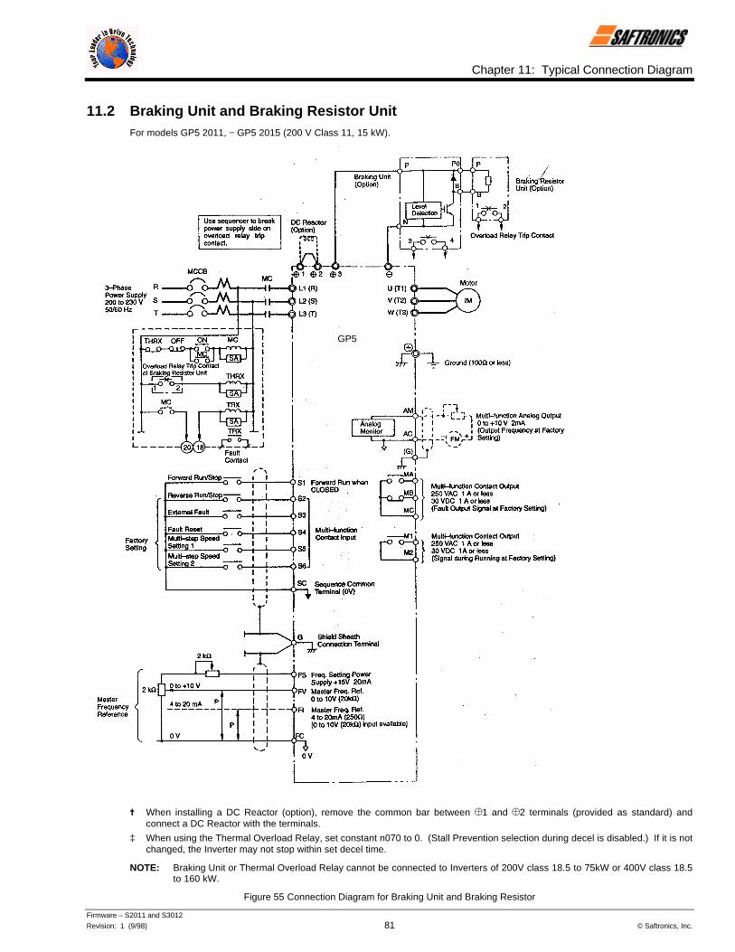
Chapter 11: Typical Connection Diagram
Firmware – S2011 and S3012
Revision: 1 (9/98) 81 © Saftronics, Inc.
11.2 Braking Unit and Braking Resistor UnitFor models GP5 2011, − GP5 2015 (200 V Class 11, 15 kW).
= When installing a DC Reactor (option), remove the common bar between ¾1 and ¾2 terminals (provided as standard) andconnect a DC Reactor with the terminals.
‡ When using the Thermal Overload Relay, set constant n070 to 0. (Stall Prevention selection during decel is disabled.) If it is notchanged, the Inverter may not stop within set decel time.
NOTE: Braking Unit or Thermal Overload Relay cannot be connected to Inverters of 200V class 18.5 to 75kW or 400V class 18.5to 160 kW.
Figure 55 Connection Diagram for Braking Unit and Braking Resistor
GP5

Chapter 11: Typical Connection Diagram
Firmware – S2011 and S3012
Revision: 1 (9/98) 82 © Saftronics, Inc.
NOTES:
12Constant List
This chapter lists the constants for the FP5/GP5.
12.1 Constant List ................................................................... 84

Chapter 12: Constant List
Firmware – S2011 and S3012
Revision: 1 (9/98) 84 © Saftronics, Inc.
12.1 Constant ListTable 27 Constant List
Constant Function Name Description FactorySetting
n001 Password
0 : n001 read and set, n002 to n108 read only1 : n001 to n034 read and set, n035 to n108 read only2 : n001 to n049 read and set, n050 to n108 read only3 : n001 to n108 read and set4 : Not used5 : Not used6 : 2-wire initialization − reset (Japanese standard)7 : 3-wire initialization − reset (Japanese standard)8 : 2-wire initialization − reset (U.S. specifications)9 : 3-wire initialization − reset (U.S. specifications)10 : 2-wire initialization – reset (European specifications)11 : 3-wire initialization – reset (European specifications)
1
n002 Operation mode selection
(Setting) (Operation) (Reference)0 : Operator Operator1 : Terminal Operator2 : Operator Terminal3 : Terminal Terminal4 : Operator Serial com5 : Terminal Serial com6 : Serial com Serial com7 : Serial com Operator8 : Serial com Terminal
3
n003 Input voltage Unit : 0.1VSetting range : 150.0 to 255.0V (510V for 400V units)
200.0V(400.0V)
n004 Stopping method selection
0 : Deceleration to stop1 : Coast to stop2 : Coast to stop with timer 13 : Coast to stop with timer 2
0
n005 Power rotation 0 : CCW1 : CW 0
n006 Reverse run prohibit 0 : Reverse run enabled1 : Reverse run disabled
0
n007 LOCAL/REMOTE key function 0 : Disabled1 : Enabled
1
n008 Stop key function 0 : STOP key is effective when operated from Digital Operator1 : STOP key is always effective 1
n009 Frequency reference setting methodfrom Digital Operator
0 : ENTER key not used1 : ENTER key used 1
n010 V/f pattern selection (same as V/fLED)
0 to E : 15 preset V/f patternsF : Custom V/f pattern with voltage limitFF : Custom V/f pattern without voltage limit
1
n011 Motor rated voltage(same as Vmtr LED)
Unit : 0.1VSetting range : 150.0 to 255.0V (510 V for 400V units)
200.0V
n012 Maximum output frequency Unit : 0.1HzSetting range : 50.0 to 400.0Hz
60.0 Hz
n013 Maximum voltage Unit : 0.1VSetting range : 0.1 to 255.0V (510 V for 400V units) 200.0V
n014 Maximum voltage output frequency Unit : 0.1HZSetting range : 0.2 to 400.0V 60.0Hz
n015 Middle output frequency Unit : 0.1HzSetting range : 0.1 to 399.9Hz
3.0Hz
n016 Middle frequency voltage Unit : 0.1VSetting range : 0.1 to 255.0V (510V for 400V units)
15.0V
n017 Minimum output frequency Unit : 0.1HzSetting range : 0.1 to 10.0Hz 1.5Hz
n018 Minimum output frequency voltage Unit : 0.1VSetting range 0.1 to 50.0V 10.0V
n019 Acceleration time 1(same as Accel LED)
Unit : 0.1 seconds (1 seconds for 1000 seconds and above)Setting range : 0.0 to 3600 seconds
10.0seconds
n020 Deceleration time 1(same as Decel LED)
Unit : 0.1 sec (1 seconds for 1000 seconds and above)Setting range : 0.0 to 3600 seconds
10.0seconds
n021 Acceleration time 2 Unit : 0.1 seconds (1 seconds for 1000 seconds and above)Setting range : 0.0 to 3600 seconds
10.0seconds
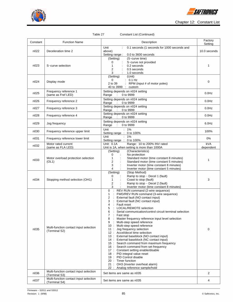
Chapter 12: Constant List
Firmware – S2011 and S3012
Revision: 1 (9/98) 85 © Saftronics, Inc.
Table 27 Constant List (Continued)
Constant Function Name Description FactorySetting
n022 Deceleration time 2Unit : 0.1 seconds (1 seconds for 1000 seconds andabove)Setting range : 0.0 to 3600 seconds
10.0 seconds
n023 S−curve selection
(Setting) (S−curve time)0 : S−curve not provided1 : 0.2 seconds2 : 0.5 seconds3 : 1.0 seconds
1
n024 Display mode
(Setting) (Unit)0 : 0.1 Hz
2 to 39 : RPM (input # of motor poles)40 to 3999 : custom
0
n025Frequency reference 1(same as Fref LED)
Setting depends on n024 settingRange : 0 to 9999 0.0Hz
n026 Frequency reference 2 Setting depends on n024 settingRange : 0 to 9999 0.0Hz
n027 Frequency reference 3 Setting depends on n024 settingRange : 0 to 9999
0.0Hz
n028 Frequency reference 4 Setting depends on n024 settingRange : 0 to 9999 0.0Hz
n029 Jog frequencySetting depends on n024 settingRange : 0 to 9999 6.0Hz
n030 Frequency reference upper limit Unit : 1%Setting range : 0 to 100% 100%
n031 Frequency reference lower limit Unit : 1%Setting range : 0 to 100%
0%
n032 Motor rated current(same as FLA LED)
Unit: 0.1A Range: 10 to 200% INV ratedUnit is 1A, when setting is more than 1000A
kVAdependent
n033Motor overload protection selection(OL1)
(Setting) (Characteristics)0 : No protection1 : Standard motor (time constant 8 minutes)2 : Standard motor (time constant 5 minutes)3 : Inverter motor (time constant 8 minutes)4 : Inverter motor (time constant 5 minutes)
1
n034 Stopping method selection (OH1)
(Setting) (Stop Method)0 : Ramp to stop − Decel 1 (fault)1 : Coast to stop (fault)2 : Ramp to stop − Decel 2 (fault)3 : Inverter motor (time constant 8 minutes)
3
n035Multi-function contact input selection(Terminal S2)
0 : REV RUN command (2-wire sequence)1 : FWD/REV RUN command (3-wire sequence)2 : External fault (NO contact input)3 : External fault (NC contact input)4 : Fault reset5 : LOCAL/REMOTE selection6 : Serial communication/control circuit terminal selection7 : Fast stop8 : Master frequency reference input level selection9 : Multi-step speed reference10 : Multi-step speed reference11 : Jog frequency selection12 : Accel/decel time selection13 : External baseblock (NO contact input)14 : External baseblock (NC contact input)15 : Search command from maximum frequency16 : Search command from set frequency17 : Constant setting enable/disable18 : PID integral value reset19 : PID Control disable20 : Timer function21 : OH3 (Inverter overheat alarm)22 : Analog reference sample/hold
0
n036 Multi-function contact input selection(Terminal S3)
Set items are same as n035 2
n037 Multi-function contact input selection(Terminal S4) Set items are same as n035 4
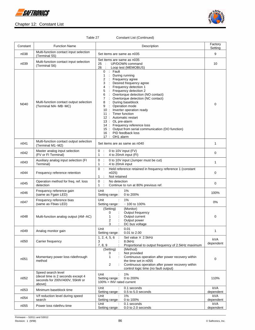
Chapter 12: Constant List
Firmware – S2011 and S3012
Revision: 1 (9/98) 86 © Saftronics, Inc.
Table 27 Constant List (Continued)
Constant Function Name Description FactorySetting
n038 Multi-function contact input selection(Terminal S5) Set items are same as n035 9
n039 Multi-function contact input selection(Terminal S6)
Set items are same as n03525 : UP/DOWN command26 : Loop test (MEMOBUS)
10
N040Multi-function contact output selection(Terminal MA−MB−MC)
0 : Fault1 : During running2 : Frequency agree3 : Desired frequency agree4 : Frequency detection 15 : Frequency detection 26 : Overtorque detection (NO contact)7 : Overtorque detection (NC contact)8 : During baseblock9 : Operation mode10 : Inverter operation ready11 : Timer function12 : Automatic restart13 : OL pre-alarm14 : Frequency reference loss15 : Output from serial communication (DO function)16 : PID feedback loss17 : OH1 alarm
0
n041Multi-function contact output selection(Terminal M1−M2)
Set items are as same as n040 1
n042Master analog input selection(FV or FI Terminal)
0 : 0 to 10V input (FV)1 : 4 to 20mA input (FI) 0
n043Auxiliary analog input selection (FITerminal)
0 : 0 to 10V input (Jumper must be cut)1 : 4 to 20mA input 1
n044 Frequency reference retention0 : Held reference retained in frequency reference 1 (constant
n025)1 : Not retained
0
n045Operation method for freq. ref. lossdetection
0 : No detection1 : Continue to run at 80% previous ref. 0
n046Frequency reference gain(same as Fgain LED)
Unit : 1%Setting range : 0 to 200% 100%
n047Frequency reference bias(same as Fbias LED)
Unit : 1%Setting range : − 100 to 100%
0%
n048 Multi-function analog output (AM−AC)
(Setting) (Monitor)0 : Output frequency1 : Output current2 : Output power3 : DC bus voltage
0
n049 Analog monitor gainUnit : 0.01Setting range : 0.01 to 2.00 1
n050 Carrier frequency1, 2, 4, 5, 6 : Set value 5 2.5kHz3 : 8.0kHz7, 8, 9 : Proportional to output frequency of 2.5kHz maximum
kVAdependent
n051Momentary power loss ridethroughmethod
(Setting) (Method)0 : Not provided1 : Continuous operation after power recovery within
the time set in n0552 : Continuous operation after power recovery within
control logic time (no fault output)
0
n052
Speed search level(decel time is 2 seconds except 4seconds for 200V/400V, 55kW orabove)
Unit : 1%Setting range : 0 to 200%100% = INV rated current
110%
n053 Minimum baseblock time Unit : 0.1 secondsSetting range : 0.5 to 5.0 seconds
kVAdependent
n054 V/f reduction level during speedsearch
Unit : 1%Setting range : 0 to 100%
kVAdependent
n055 Power loss ridethru time Unit : 0.1 secondsSetting range : 0.0 to 2.0 seconds
kVAdependent

Chapter 12: Constant List
Firmware – S2011 and S3012
Revision: 1 (9/98) 87 © Saftronics, Inc.
Table 27 Constant List (Continued)
Constant Function Name Description FactorySetting
n056 Automatic retry attempts Unit : 1 timeSetting range : 0 to 10 0
n057 Fault contact selection duringautomatic retry
0 : Closed during fault retry1 : Open during fault retry
0
n058 Jump frequency 1 Unit : 0.1HzSetting range : 0.0 to 400.0Hz 0.0Hz
n059 Jump frequency 2 Unit : 0.1HzSetting range : 0.0 to 400.0Hz 0.0Hz
n060 Jump frequency range Unit : 0.1HzSetting range : 0.0 to 400.0Hz 1.0Hz
n061 Elapsed timer selection 0 : Accumulated time during power on1 : Accumulated time during running
1
n062 Elapsed timer 1 Unit : 1 hourRange : 0 to 9999 0
n063 Elapsed timer 2 Unit : 10,000 hoursRange : 0 to 27 0
n064 DC Injection Braking currentUnit : 1%Setting range : 0 to 100%100% = INV rated current
50%
n065 DC Injection Braking time at stop Unit : 0.1 secondsRange : 0.0 to 10.0 seconds 0.5 seconds
n066 DC Injection Braking time at start Unit : 0.1 secondsRange : 0.0 to 10.0 seconds
0.0 seconds
n067 Torque compensation gain Unit : 0.1Range : 0.0 to 3.0 1.0
n068 Motor line to line resistanceUnit : 0.001 Ω (0.01 Ω for
10.00 Ω or above)Setting range : 0.000 to 65.53
kVAdependent
n069 Iron loss Unit : 0WSetting range : 0 to 9999W
Normally, no adjustmentis necessary.
kVAdependent
n070 Stall Prevention during deceleration 0 : Disabled1 : Enabled 1
n071 Stall Prevention level duringacceleration
Unit : 1%Setting range : 30 to 200%When level is set to 200%, Stall Prevention during acceleration isdisabled.
kVAdependent
n072 Stall Prevention level during runningUnit : 1%Setting range : 30 to 200%When level is set to 200%, Stall Prevention running is disabled.
kVAdependent
n073 Frequency detection(multi-function contact output)
Unit : 0.1HzSetting range : 0.0 to 400Hz 0.0Hz
n074Overtorque detection functionselection(OL3)
(Setting) (Function)0 : Detection disabled1 : Detected during constant-speed running, and
operation continues after detection.2 : Detected during running, and operation continues
after operation3 : Detected during constant-speed running, and
Inverter output is shut OFF during detection.4 : Detected during running, and Inverter output is
shut OFF during detection.
0
n075 Overtorque detection level (OL3)Unit : 1%Setting range : − 30 to 200%100% = INV rated current
160%
n076 Overtorque detection time (OL3) Unit : 0.1 secondsSetting range : 0.0 to 10.0 seconds 0.1 seconds
n077 ON-delay timer Unit : 0.1 secondsSetting range : 0.0 to 25.5seconds
0.0 seconds
n078 OFF-delay timerUnit : 0.1 secondsSetting range : − 0.0 to 25.5 seconds
0.0 seconds
n079 dB resistor overheat function (rH) 0 : No dB protection calculated or provided1 : Protection provided for installed Saftronics resistor only
0
n080 Input phase loss detection level (SPI)Unit : 1%Setting range : 1 to 100%When setting is 100%, this function is disabled
7%
n081 Input phase loss detection delay time(SPI)
Unit : 1 (1.28 seconds)Setting range : 2 to 255 (2.56 to 326.4 seconds)
(10.24seconds)
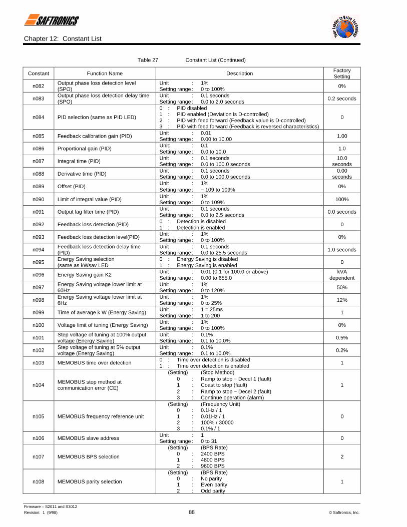
Chapter 12: Constant List
Firmware – S2011 and S3012
Revision: 1 (9/98) 88 © Saftronics, Inc.
Table 27 Constant List (Continued)
Constant Function Name Description FactorySetting
n082 Output phase loss detection level(SPO)
Unit : 1%Setting range : 0 to 100% 0%
n083 Output phase loss detection delay time(SPO)
Unit : 0.1 secondsSetting range : 0.0 to 2.0 seconds
0.2 seconds
n084 PID selection (same as PID LED)
0 : PID disabled1 : PID enabled (Deviation is D-controlled)2 : PID with feed forward (Feedback value is D-controlled)3 : PID with feed forward (Feedback is reversed characteristics)
0
n085 Feedback calibration gain (PID) Unit : 0.01Setting range : 0.00 to 10.00 1.00
n086 Proportional gain (PID) Unit: : 0.1Setting range : 0.0 to 10.0
1.0
n087 Integral time (PID) Unit : 0.1 secondsSetting range : 0.0 to 100.0 seconds
10.0seconds
n088 Derivative time (PID) Unit : 0.1 secondsSetting range : 0.0 to 100.0 seconds
0.00seconds
n089 Offset (PID)Unit : 1%Setting range : − 109 to 109%
0%
n090 Limit of integral value (PID) Unit : 1%Setting range : 0 to 109% 100%
n091 Output lag filter time (PID) Unit : 0.1 secondsSetting range : 0.0 to 2.5 seconds
0.0 seconds
n092 Feedback loss detection (PID) 0 : Detection is disabled1 : Detection is enabled
0
n093 Feedback loss detection level(PID) Unit : 1%Setting range : 0 to 100% 0%
n094 Feedback loss detection delay time(PID)
Unit : 0.1 secondsSetting range : 0.0 to 25.5 seconds 1.0 seconds
n095 Energy Saving selection(same as kWsav LED
0 : Energy Saving is disabled1 : Energy Saving is enabled
0
n096 Energy Saving gain K2 Unit : 0.01 (0.1 for 100.0 or above)Setting range : 0.00 to 655.0
kVAdependent
n097 Energy Saving voltage lower limit at60Hz
Unit : 1%Setting range : 0 to 120% 50%
n098 Energy Saving voltage lower limit at6Hz
Unit : 1%Setting range : 0 to 25% 12%
n099 Time of average k W (Energy Saving) Unit : 1 = 25msSetting range : 1 to 200
1
n100 Voltage limit of tuning (Energy Saving) Unit : 1%Setting range : 0 to 100% 0%
n101 Step voltage of tuning at 100% outputvoltage (Energy Saving)
Unit : 0.1%Setting range : 0.1 to 10.0% 0.5%
n102 Step voltage of tuning at 5% outputvoltage (Energy Saving)
Unit : 0.1%Setting range : 0.1 to 10.0% 0.2%
n103 MEMOBUS time over detection 0 : Time over detection is disabled1 : Time over detection is enabled
1
n104 MEMOBUS stop method atcommunication error (CE)
(Setting) (Stop Method)0 : Ramp to stop − Decel 1 (fault)1 : Coast to stop (fault)2 : Ramp to stop − Decel 2 (fault)3 : Continue operation (alarm)
1
n105 MEMOBUS frequency reference unit
(Setting) (Frequency Unit)0 : 0.1Hz / 11 : 0.01Hz / 12 : 100% / 300003 : 0.1% / 1
0
n106 MEMOBUS slave address Unit : 1Setting range : 0 to 31 0
n107 MEMOBUS BPS selection
(Setting) (BPS Rate)0 : 2400 BPS1 : 4800 BPS2 : 9600 BPS
2
n108 MEMOBUS parity selection
(Setting) (BPS Rate)0 : No parity1 : Even parity2 : Odd parity
1
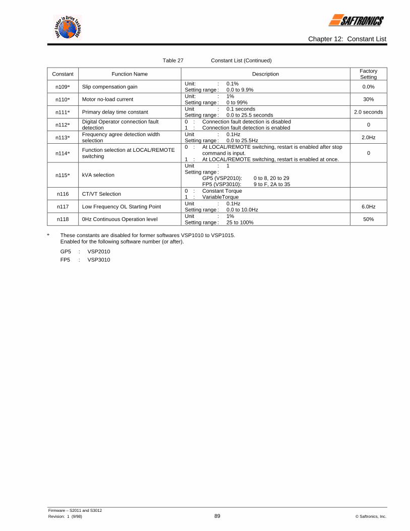
Chapter 12: Constant List
Firmware – S2011 and S3012
Revision: 1 (9/98) 89 © Saftronics, Inc.
Table 27 Constant List (Continued)
Constant Function Name Description FactorySetting
n109∗ Slip compensation gain Unit: : 0.1%Setting range : 0.0 to 9.9% 0.0%
n110∗ Motor no-load current Unit: : 1%Setting range : 0 to 99%
30%
n111∗ Primary delay time constant Unit : 0.1 secondsSetting range : 0.0 to 25.5 seconds 2.0 seconds
n112∗Digital Operator connection faultdetection
0 : Connection fault detection is disabled1 : Connection fault detection is enabled 0
n113∗Frequency agree detection widthselection
Unit : 0.1HzSetting range : 0.0 to 25.5Hz 2.0Hz
n114∗Function selection at LOCAL/REMOTEswitching
0 : At LOCAL/REMOTE switching, restart is enabled after stop command is input.
1 : At LOCAL/REMOTE switching, restart is enabled at once.0
n115∗ kVA selection
Unit : 1Setting range :
GP5 (VSP2010): 0 to 8, 20 to 29FP5 (VSP3010): 9 to F, 2A to 35
n116 CT/VT Selection 0 : Constant Torque1 : VariableTorque
n117 Low Frequency OL Starting Point Unit : 0.1HzSetting range : 0.0 to 10.0Hz 6.0Hz
n118 0Hz Continuous Operation level Unit : 1%Setting range : 25 to 100%
50%
∗ These constants are disabled for former softwares VSP1010 to VSP1015.Enabled for the following software number (or after).
GP5 : VSP2010
FP5 : VSP3010

Chapter 12: Constant List
Firmware – S2011 and S3012
Revision: 1 (9/98) 90 © Saftronics, Inc.
NOTES:

13Digital Operator Monitor Display
This chapter describes the monitor displays of the Digital Operator of the FP5/GP5.
13.1 Digital Operator Monitor Display ................................... 92

Chapter 13: Digital Operator Monitor Display
Firmware – S2011 and S3012
Revision: 1 (9/98) 92 © Saftronics, Inc.
13.1 Digital Operator Monitor DisplayThe following table shows the contents of the Digital Operator monitor display.
Table 28 Digital Operator Monitor Display
LED Name Description
Fref Frequency reference • Frequency reference can be monitored/set.• Setting/display unit depends on display mode (n024).
Fout Output frequency • Output frequency can be monitored.• Display unit depends on display mode (n024).
Iout Output current Output current can be monitored in units of 0.1 A (1 A for 1000 A and above).
kWout Output voltage Output voltage can be monitored in units of 0.1 kW (1 kW for 1000 k and above).
F/RFWD/REV RUNcommand
• FWD/REV RUN command can be set/monitored.• Setting enabled during RUN command from Digital Operator.• FWD run displays For, REV run displays rev.
The following contents can be monitored.
No. Contents
U−01 Frequency reference (same as Fref)
U−02 Output frequency (same as Fout)
U−03 Output current (same as Iout)
U−04 Output voltage reference can be monitored in units of 1 V
U−05 DC voltage can be monitored in units of 1 V
U−06 Output power (same as kWout)
Input terminal status can be monitored (Terminals S1 to S6)
U−07
Inverter status can be monitored
Montr Monitor
U−08
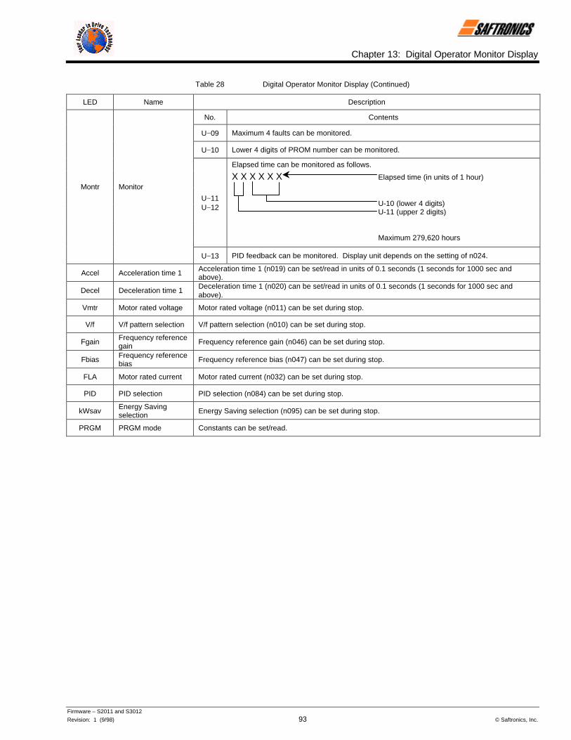
Chapter 13: Digital Operator Monitor Display
Firmware – S2011 and S3012
Revision: 1 (9/98) 93 © Saftronics, Inc.
Table 28 Digital Operator Monitor Display (Continued)
LED Name Description
No. Contents
U−09 Maximum 4 faults can be monitored.
U−10 Lower 4 digits of PROM number can be monitored.
Elapsed time can be monitored as follows.
U−11U−12
X X X X X X Elapsed time (in units of 1 hour)
U-10 (lower 4 digits)U-11 (upper 2 digits)
Maximum 279,620 hours
Montr Monitor
U−13 PID feedback can be monitored. Display unit depends on the setting of n024.
Accel Acceleration time 1 Acceleration time 1 (n019) can be set/read in units of 0.1 seconds (1 seconds for 1000 sec andabove).
Decel Deceleration time 1 Deceleration time 1 (n020) can be set/read in units of 0.1 seconds (1 seconds for 1000 sec andabove).
Vmtr Motor rated voltage Motor rated voltage (n011) can be set during stop.
V/f V/f pattern selection V/f pattern selection (n010) can be set during stop.
Fgain Frequency referencegain Frequency reference gain (n046) can be set during stop.
Fbias Frequency referencebias Frequency reference bias (n047) can be set during stop.
FLA Motor rated current Motor rated current (n032) can be set during stop.
PID PID selection PID selection (n084) can be set during stop.
kWsav Energy Savingselection Energy Saving selection (n095) can be set during stop.
PRGM PRGM mode Constants can be set/read.

Chapter 13: Digital Operator Monitor Display
Firmware – S2011 and S3012
Revision: 1 (9/98) 94 © Saftronics, Inc.
NOTES:

INDEX
Firmware – S2011 and S3012
Revision: 1 (9/98) 95 © Saftronics, Inc.
3-phase power supply, 10
AAC reactor, 11accel/decel time, 70acceleration time, 84, 92adjusting frequency setting signal, 40adjusting frequency upper and lower limits, 41alarm display, 69allowable frequency fluctuation, 70allowable voltage fluctuation, 70ambient temperature, 64, 70analog input signal, 21analog monitor, 10analog monitor gain, 86analog output signal, 21analog reference sample/hold selection, 52applying DC injection braking, 49approximate mass, 77automatic restart after momentary power loss, 42automatic retry attempts, 86auxiliary analog input selection, 54, 86
Bbraking resistor unit, 10, 13, 14braking resistor unit overheat, 68braking resistor failure, 68braking torque, 70braking unit, 13, 14, 80
Ccalibrating frequency meter or ammeter, 46carrier frequency, 12, 86closed-loop connector, 20coast to stop, 48coast to stop with timer, 49connection diagram, 10constant list, 84constant selection/initialization, 36constant setting error, 68constant operation by automatic fault reset, 45control characteristics, 70control circuit, 21control circuit fault, 67control circuit terminal, 21control circuit terminal signal, 29control circuit undervoltage, 66control method, 70control PC board, 64cooling fan, 64CPU A/D converter fault, 67Custom V/f pattern, 38
DdB resistor overheat function, 87DC injection braking at start, 46DC injection braking current, 49, 87DC injection braking time at start, 8DC injection braking time at stop, 49, 87DC reactor, 11, 13, 14deceleration time, 84, 93deceleration to stop, 48derivative time, 88desired frequency agree signal, 56digital operator, 6, 27, 32digital operator connection fault detection, 89dimensions, 76display mode, 185
EEEPROM fault, 67elapsed timer, 87elapsed timer selection, 87electronic thermal overload relay, 70elevation, 70emergency stop circuit, ii, 10enclosed wall-mounted type, 3, 70enclosure, 3energy saving control mode, 59energy saving gain K2, 59, 88energy saving selection, 88, 93energy saving tuning, 59energy saving voltage lower limit, 59, 88environment, 70excessive ripple in bus bar, 67external baseblock, 68external fault, 10, 21external fault from serial communication, 66
Ffault contact selection during automatic retry, 87fault diagnosis, 64, 66fault output signal, 10fault reset, 10, 21feedback calibration gain, 88feedback loss detection, 88feedback loss detection delay time, 88feedback loss detection level , 88forward run, 10frequency accuracy, 70frequency agree detection width selection, 89frequency agree signal, 56frequency control range, 70frequency detection, 44, 87frequency reference, 25, 85, 92frequency reference bias, 40, 86, 93frequency reference gain, 40, 86, 93frequency reference input, 21frequency reference lower limit, 41, 85frequency reference retention, 54, 86

INDEX
Firmware – S2011 and S3012
Revision: 1 (9/98) 96 © Saftronics, Inc.
frequency reference setting method from digital operator, 84frequency reference upper limit, 41, 85frequency resolution, 70frequency setting power supply, 10frequency setting signal, 70function selection at LOCAL/REMOTE switching, 92FWD/REV run command, 92
Gground fault, 70ground fault interrupter, 11ground terminal, ii, 11grounding, 12, 66
Hheatsink overheat, 66, 70heatsink overheating, 68humidity, 70
Iinput phase loss detection delay time, 87input phase loss detection level, 87input voltage, 84instantaneous overcurrent, 70intake air temperature, 8integral time, 88Inverter capacity, 70Inverter kVA setting fault, 68Inverter motor, 57Inverter overheat pre-alarm, 68Inverter overload, 66Iron loss, 87
Jjog frequency, 85jump frequency, 44, 87jump frequency range, 87
KkVA selection, 89
Llimit of integral value, 88line voltage, 26load short-circuit, 66LOCAL, 25LOCAL/REMOTE key function, 84LOCAL/REMOTE selection, 51location, 70loop test, 53
MMagnetic Contactor, 11, 12magnetic starter, 12
main circuit, 11main circuit configuration, 15main circuit fault, 66main circuit power supply, iii, ivmain circuit terminal, 13, 14main circuit undervoltage, 66master analog input selection, 53, 86master frequency reference, 10maximum applicable motor output, 3, 70maximum output frequency, 84maximum output voltage, 70maximum voltage, 84maximum voltage output frequency, 84MC fault, 66middle frequency voltage, 84middle output frequency, 84minimum baseblock time, 86minimum output frequency, 84minimum output frequency voltage, 84MEMOBUS BPS selection, 88MEMOBUS frequency reference unit, 61, 88MEMOBUS parity selection, 88MEMOBUS slave address, 61, 88MEMOBUS, stop method at communication error, 88MEMOBUS time over detection, 88MEMOBUS transmission error, 68MEMOBUS transmission fault, 67MEMOBUS transmission waiting, 68molded-case circuit breaker, iv, 11, 64momentary power loss, 70momentary power loss ridethrough method, 86monitor, 92monitor display, 92motor line to line resistance, 87motor no-load current, 89motor overload, 66motor overload detection, 57motor overload protection, 70motor overload protection selection, 57, 85motor rated current, 57, 85, 93motor rated voltage, 84, 93multi-function analog output, 10, 86multi-function contact input, 10multi-function contact input selection, 85, 86multi-function contact input setting error, 68multi-function contact output, 10multi-function contact output selection, 86multi-step speed reference, 21multi-step speed selection, 39multi-step speed setting, 10
Nnameplate, 2No. of V/f patterns, 70
OOFF-delay timer, 87offset, 88

INDEX
Firmware – S2011 and S3012
Revision: 1 (9/98) 97 © Saftronics, Inc.
ON-delay timer, 87open chassis type, 3, 70open phase, 69operating at low speed, 39operating coasting motor without trip, 45operating method for frequency reference loss
detection, 54, 86operation mode selection, 60, 84output characteristics, 70output current, 92output frequency, 10, 92output frequency resolution, 70output lag filter time, 88output open-phase, 67output phase loss detection delay time, 88output phase loss detection level, 88output terminal, 12output voltage, 92OV during stop, 68overcurrent, 66overload, 70overload capacity, 70overload relay trip contact, 80overtorque detection, 66, 68overtorque detection function selection, 43, 87overtorque detection level, 43, 87overtorque detection time, 43, 87overvoltage, 66, 70
Ppassword, 84periodic inspection, 64phase advancing capacitor, 12photo-coupler insulation, 21PID selection, 88, 93power charge indication, 70power loss ridethrough time, 86power rotation, 84power supply, 70preset V/f pattern, 37PRGM mode, 93primary delay time constant 89proportional gain, 88protective function, 70
Qquick-start LED, 32
Rrated input voltage and frequency, 70rated output current, 70rated output frequency, 70reducing motor noise or leakage current, 47REMOTE, 25reverse run, 10reverse run prohibit, 38, 84
Ss-curve selection, 87selecting stopping method, 48sequence common, 10sequence control input common, 21sequence input signal, 21sequence output signal, 21serial communication/control circuit terminal selection, 51shield sheath connection terminal, 10shielded wire, 11signal during running, 10simultaneous forward/reverse run commands, 68sine wave PWM, 70slip compensation gain, 89soft-start characteristics, 42specification, 70speed search command, 45speed search level, 86stall prevention, 70stall prevention during deceleration, 87stall prevention level during acceleration, 87stall prevention level during running, 87standard motor, 57step voltage of tuning, 60, 88stop key function, 84stopping method selection, 84, 85storage temperature, 70surge suppressor, 12switching frequency, 12
Tterminal function at 2-wire sequence selection, 51terminal function at 3-wire sequence selection, 51terminal screw, 17, 18, 19test run, 26, 27thermal overload relay, 12thermistor, 70time of average kW, 88timer function, 52torque compensation gain, 56, 87torque detection, 43twisted shielded wire, 17, 19twisted-pair shielded wire, 11, 22
Uundevoltage, 70undervoltage detection, 68UP/DOWN command, 52using analog input signals, 53using frequency meter or ammeter, 46using output signals, 55using sequence input signals, 50using two accel/decel times, 41

INDEX
Firmware – S2011 and S3012
Revision: 1 (9/98) 98 © Saftronics, Inc.
VV/f data setting error, 68V/f pattern selection, 84, 93V/f reduction level during speed search, 86vibration, 70voltage limit of tuning, 59, 88
Wwire size, 17, 18, 19withstand voltage test, iii, 10


5580 Enterprise Parkway, Fort Myers, Florida 33905 l Telephone (941) 693-7200 l Fax (941) 693-2431Web Address: http://www.saftronics.com
REV 1 (9/98)P/N 027-20421998