Embed Size (px)
Citation preview

02826
LinkNet ® Optionfor use with 723 Digital Controls
Operation Manual
WOODWARD GOVERNOR COMPANY
Manual 02826

Woodward Governor Company reserves the right to update any portion of this publication at any time. Informationprovided by Woodward Governor Company is believed to be correct and reliable. However, no responsibility isassumed by Woodward Governor Company unless otherwise expressly undertaken.
© 1997 by Woodward Governor CompanyAll Rights Reserved
!WARNINGRead this entire manual and all other publications pertaining to the work tobe performed before installing, operating, or servicing this equipment.Practice all plant and safety instructions and precautions. Failure to followinstructions can cause personal injury and/or property damage.
The engine, turbine, or other type of prime mover should be equipped withan overspeed (overtemperature, or overpressure, where applicable)shutdown device(s), that operates totally independently of the prime movercontrol device(s) to protect against runaway or damage to the engine,turbine, or other type of prime mover with possible personal injury or loss oflife should the mechanical-hydraulic governor(s) or electric control(s), theactuator(s), fuel control(s), the driving mechanism(s), the linkage(s), or thecontrolled device(s) fail.
!CAUTIONTo prevent damage to a control system that uses an alternator or battery-charging device, make sure the charging device is turned off beforedisconnecting the battery from the system.
!CAUTIONElectronic controls contain static-sensitive parts. Observe the followingprecautions to prevent damage to these parts.•••• Discharge body static before handling the control (with power to the
control turned off, contact a grounded surf ace and maintain contactwhile handling the control).
•••• Avoid all plastic, vinyl, and styrofoam (except antistatic versions)around printed circuit boards.
•••• Do not touch the components or conductors on a printed circuit boardwith your hands or with conductive devices.

Manual 02826 LinkNet Option
Woodward Governor Company i
Contents
CHAPTER 1 LINKNET I/O NETWORK ....................................................... 1Introduction ..................................................................................................... 1Network Architecture ....................................................................................... 1Hardware ......................................................................................................... 1I/O Module Specification ................................................................................. 3Individual I/O Module Specifications ................................................................ 5Cable Length and Number of LinkNet I/O Modules .......................................... 6LinkNet I/O Module Descriptions ..................................................................... 6
Discrete Input Module .............................................................................. 74-20 mA Input Module ............................................................................. 8Thermocouple Input Module ..................................................................... 9RTD Input Module ................................................................................. 10Relay Output Module ............................................................................. 114-20 mA Output Module ......................................................................... 12
Troubleshooting Flowchart ............................................................................. 13
CHAPTER 2 ELECTROSTATIC DISCHARGE AWARENESS .................. 23
CHAPTER 3 SERVICE OPTIONS .............................................................. 25Product Service Options ................................................................................. 25
Replacement/Exchange ........................................................................... 25Flat Rate Repair ..................................................................................... 26Flat Rate Remanufacture ........................................................................ 26
Returning Equipment for Repair ..................................................................... 26Packing a Control ................................................................................... 27Additional Instructions ............................................................................ 27
Replacement Parts Information ....................................................................... 27How to Contact Woodward ............................................................................ 28Other Service Facilities .................................................................................. 28Additional Aftermarket Product Support Services ........................................... 28System Troubleshooting Guide ....................................................................... 29Technical Assistance ...................................................................................... 33

LinkNet Option Manual 02826
ii Woodward Governor Company
Illustrations
1-1. Direct Wired Network ....................................................................... 31-2. Network Wired Via Stubs ................................................................. 31-3. LinkNet Relay Contacts .................................................................... 51-4. Discrete Input Module Block Diagram ............................................... 71-5. 4-20 mA Input Module Block Diagram .............................................. 81-6. Thermocouple Input Module Block Diagram ..................................... 91-7. RTD Input Module Block Diagram ................................................. 101-8. Relay Output Module Block Diagram .............................................. 111-9. 4-20 mA Output Module Block Diagram ......................................... 121-10. Troubleshooting Flowchart ......................................................... 14/151-11. Discrete In Module Wiring Diagram ................................................ 161-12. Analog In Module Wiring Diagram ................................................. 171-13. Thermocouple Module Wiring Diagram ........................................... 181-14. RTD Module Wiring Diagram ......................................................... 191-15. Discrete Out Module Wiring Diagram ............................................. 201-16. Analog Out Module Wiring Diagram ............................................... 21

Manual 02826 LinkNet Option
Woodward Governor Company 1
Chapter 1LinkNet ® I/O Network
Introduction
The LinkNet® option provides distributed I/O capabilities for the 723 controlsystem. The LinkNet I/O modules are well suited for non-time-critical controlfunctions like sequencing and monitoring.
Other manuals that may prove helpful are:02007 DSLC Digital Synchronizer and Load Control02758 723 Hardware Manual02784 723 Software/DSLC Compatible02785 723 Software/Analog Load Share
Network Architecture
An I/O network consists of a 723 LinkNet channel, which provides independentnetwork trunks of up to 60 I/O modules. The LinkNet I/O modules, or nodes, oneach trunk are attached to the 723 via a single twisted pair wire.
Each LinkNet I/O module has two rotary switches that are used to set its networkaddress. On installation, these switches must be dialed so that the I/O module'snumber, 1–60, matches the network address defined for this I/O module in theapplication program. The I/O modules may be placed in any order on the network,and gaps are allowed in the address sequence.
Hardware
Each network consists of one LinkNet channel of a 723 and many I/O modules.The I/O modules include thermocouple, RTD, 4–20 mA, and discrete inputmodules, as well as 4–20 mA and relay output modules. All of the analog modulesconsist of six channels per module. The relay output module contains eightchannels, and the discrete input module has 16 channels.
Each I/O module is housed in a plastic, field termination module-type package forDIN rail mounting. The LinkNet I/O modules can be mounted in the controlcabinet or in any convenient location in the vicinity of the engine or turbine thatmeets the temperature and vibration specifications. Each I/O module must begrounded to the DIN rail through a grounding block (Woodward part number1604-813).

LinkNet Option Manual 02826
2 Woodward Governor Company
All LinkNet I/O modules communicate with the 723 through shielded twisted pairwiring. The specifications for the LinkNet system require that listed level V typecable be used. The network may be wired directly from I/O module to I/O module,as shown in Figure 1-1, or the I/O modules may be connected to the network viastubs, as in Figure 1-2. A termination network (Woodward part number 9905-760) must be installed at the last LinkNet I/O module on the network. There is nopolarity associated with the network wiring. For optimum EMC performance, thenetwork cable shield should be landed at each I/O module, and the exposed wirelength limited to 25 mm (1 inch). At the 723, the outer insulation should bestripped and the bare shield landed to the chassis.
All field wiring should be shielded. The shield should be landed in the terminalblock provided, and the exposed wiring, after the shield is separated, should belimited to 25 mm.
☞NOTEThe LinkNet modules should always be mounted in a cabinet, or beotherwise operator inaccessible. The m odules should be accessedonly for maintenance purposes, in which case, the ESD procedures inChapter 2 should be followed.
For Lloyd’s Register of Shipping applications, the power to each I/O module mustbe transient-protected through the use of Termitab-UK 5/24 AC suppressors (fromPhoenix Contact). Up to six I/O modules can be protected by one set (1 pair) ofsuppressors. Also, the power for the Discrete Inputs must be transient-protected.When the power is provided by a power source external to the Discrete Inputmodule, the power requires the same suppressors (Phoenix Contact UK 5/24 AC)required for input power for all I/O modules (see Figure 1-1).
Use only recommended shielded twisted pair cabling for the LinkNet network.Correct cable is available from Woodward, Belden, or other suppliers providingan equivalent cable.
Woodward part number 2008-349
BeldenPO Box 1980Richmond IN 47375(317) 983-5200
Belden PartNumber Description9207 PVC 20 AWG shielded. NEC Type CL2, CSA cert. PCC FT 1.89207 Teflon 20 AWG shielded, Plenum version. NEC Type CMP, CSA
cert. FT 4.YR28867 PVC 22 AWG shieldedYQ28863 Plenum 22 AWG shielded

Manual 02826 LinkNet Option
Woodward Governor Company 3
Figure 1-1. Direct Wired Network
Figure 1-2. Network Wired Via Stubs
I/O Module Specifications
Accuracy1% at 25 °C without field calibration
Power Supply Input18 to 32 Vdc
IsolationNetwork to I/O channel: 277 VacPower supply input to network: 277 VacI/O channel to I/O channel: 0 VPower supply input to I/O channel: 500 Vdc except for discrete inputs,
discrete input power comes directly from power supply input

LinkNet Option Manual 02826
4 Woodward Governor Company
Throughput TimesThe following are the formulas used to calculate the scan time of the LinkNetsystem. The scan time is defined as the period, in milliseconds, in which all nodeswill send a message to the master node containing information about its externalstimulus. The input values are gathered, and the output values are updated, by thenodes at the start of the scan period.
The scan time (ST) calculations are based on the quantity and types ofInput/Output node (ION) used. The types considered here are the output typenodes (OTN) and the input type nodes (ITN). The GAP allows us to set up thequantity of OTNs that will send readback data during the scan cycle by setting theOUT_UPDATE field. Due to the method that is used within the software, thetolerance for these figures is +15–10 ms.
If the quantity of OTN is less than or equal to 2, the formula to use is:typical ST =(ION*5) + 95 (ms)maximum ST =(ION*5) + 130 (ms)
If the quantity of OTN is greater than 2, the formula to use is:typical ST =(ITN*5) + (OUT_UPDATE*5) + (OTN*10) + 65 (ms)maximum ST =(ITN*5) + (OUT_UPDATE*5) + (OTN*10) + 100 (ms)
This scan time is how often the messages are sent, but the time from a stimulus todetection by the master’s rate groups can be very much different, as can be seenbelow.
quickest time for throughput =scan time (ms)longest time for throughput =(scan time*2) – 15
+ rate group the LN_GROUP is set to(ms)
For example—Assume that the LN_GROUP is in RG1 and this is set to run every80 ms, and that we also have one 4–20 mA input node connected to the network.
typical scan time =(1*5) + 95 =100 msquickest throughput =typical scan time =100 mslongest throughput =(100*2) + 80 – 15 =265 ms
When the network is of a smaller size, the rate group setting of the LN_GROUPcan have an impact on the longest throughput value, but note that by increasingthe rate group setting, you are loading the processor more.
Field Wiring2 mm2 (14 AWG) maximum wire size
Temperature Range–40 to +55 °C
UL Listed ComponentClass 1, Division 2, Groups A, B, C, and D, when wired in accordance with
NEC Class 1 Div. 2 wiring methods

Manual 02826 LinkNet Option
Woodward Governor Company 5
Shock and VibrationUS Mil-Std-810, 30 Gs sine wave at 11 msUS Mil-Std-167, 18-50 Hz
EMCEmissions: EN 55011, Class A, Group 1Immunity: EN 50082-2
Discrete Input Current13.1 mA per channel when “on” (@ 24 V)
Relay ContactsRatings: 5.0 A @ 28 Vdc resistive 0.5 A @ 115 Vac resistive
Figure 1-3. LinkNet Relay Contacts
Individual I/O Module Specifications
I/O ModuleType
Number ofChannels
Resolution(bits)
TempCoefficient(ppm/°C)
InputImpedance
PowerRequired at24 V input
Discrete Input 16 N/A N/A N/A 6.5 WRelay Output 8 N/A N/A N/A 5.0 W4-20 mA Inputwith 24 V
6 12 235 250 Α 5.3 W
4-20 mA Input 6 12 235 250 Α 2.4 W4-20 mA Out 6 12 250 N/A 6.0 WRTD Input 6 12 290 2.2 MΑ 3.1 WThermocoupleInput (J or Ktype +1 AD592)
6+1 coldjunction
12 235 2 MΑ 2.4 W

LinkNet Option Manual 02826
6 Woodward Governor Company
Cable Length and Number of LinkNet I/O Modules
Specification 0 to 55 °C –20 to +55 °C –40 to +55 °CMaximum network cable length 150 m 150 m 50 mMaximum number of I/O modules 60 32 20Maximum stub length 300 mm 300 mm 300 mm
LinkNet I/O Module Descriptions
The FAULT LED denotes the status of the module processor, and will be offduring normal operation. If the FAULT LED is on or is blinking, and cyclingpower to the module does not change it, then the I/O module should be replaced.
The module address circuit reads the selected module address from the rotaryswitches on each node. This address should correspond to the address of the I/Omodule hardware in the application program. If these rotary switches are setincorrectly, the node will not communicate with the 723, and a “no message” faultwill be annunciated through the application program. If two nodes are set to thesame address, an “address” fault will be annunciated through the applicationprogram, and both nodes will not function. If the node address switches arechanged, power to the module must be cycled before it will read the new moduleaddress and change its communication accordingly.
A “type” fault is annunciated through the application program when the wrongmodule type is installed at a given address. For example, installing a thermocouplemodule in place of an RTD module generates a type fault. If an output nodereceives data intended for a different module type, it will not update its outputs,and will set them to the “off” state when its watchdog timer times out.
No-message faults, address faults, and type faults can be latching or non-latching(selectable within the 723 control). When these faults occur for an input module,the application program can give default values for each channel.
Output modules contain readback circuits to verify proper operation of eachoutput channel. Analog input modules monitor a reference voltage to verify properoperation of the A/D converter. Appropriate faults are annunciated through theapplication program.
The LinkNet system accommodates hot-replacement of faulty nodes. Whenreplacing a node, the network cable connections must remain intact. A faulty nodecan be removed from the network by pulling both terminal blocks out of theirheaders, and removing the node from the DIN rail. The address switches of thereplacement node should be set to match those of the faulty node. The replacementnode can then be mounted on the DIN rail, and the terminal blocks pushed into theheaders. It may be necessary to reset the node through the application program toreinitiate communications with the 723 and to clear the “no message” fault.

Manual 02826 LinkNet Option
Woodward Governor Company 7
Discrete Input Module
Figure 1-4 is a block diagram of the Discrete Input module. The module receivesinformation from field switches and relays. Power is provided for these contacts,on four terminal blocks, TB-5 through TB-8. The input power on TB-2 may alsobe used, but does not have the benefit of an internal fuse and some filtering,therefore external fusing should be provided. The state of each discrete input ispassed through an optoisolator and an LED to the shift register. In this manner,the LEDs will light when a contact is closed. The module processor receives thisinformation and transmits it through the transceiver to the 723.
Figure 1-4. Discrete Input Module Block Diagram

LinkNet Option Manual 02826
8 Woodward Governor Company
4–20 mA Input Module
Figure 1-5 is a block diagram of the 4–20 mA input module. The module receivesinformation from 4–20 mA sources, such as transducers. Power is provided forthese transducers on one version of the module, but all module inputs must use thepower provided. No inputs may use a separate power source, as all of thenegatives are tied together and to 24 V common. The advantage of this moduleversion is that it simplifies wiring to devices such as transducers that requireexternal power. Each input is converted to a 0–5 V signal, and then multiplexed toa voltage-to-frequency converter. The module processor reads the period of thissignal and converts it to a count, which it transmits through the transceiver to the723.
Figure 1-5. 4–20 mA Input Module Block Diagram

Manual 02826 LinkNet Option
Woodward Governor Company 9
Thermocouple Input Module
Figure 1-6 is a block diagram of the thermocouple input module. The modulereceives information from thermocouples, which can be either J or K type. Thetype is selected in the application program. It also has an AD592 ambienttemperature sensor mounted on the module for cold junction temperature sensing.The cold junction compensation is performed in software. There is a fail high anda fail low version of the module, selected by jumpers on the board, which allow theinput channels to be pulled high or low on an open input. Each input ismultiplexed to a voltage-to-frequency converter. The module processor reads theperiod of this signal and converts it to a count, which it transmits through thetransceiver to the 723.
Figure 1-6. Thermocouple Input Module Block Diagram

LinkNet Option Manual 02826
10 Woodward Governor Company
RTD Input Module
Figure 1-7 is a block diagram of the RTD input module. A 1 or 2 mA source isprovided for each input. The module receives voltages from six 100 or 200 Α,3-wire RTDs. Each voltage is compensated for line resistance, and then ismultiplexed to a voltage-to-frequency converter. The module processor reads theperiod of this signal and converts it to a count, which it transmits through thetransceiver to the 723.
Figure 1-7. RTD Input Module Block Diagram

Manual 02826 LinkNet Option
Woodward Governor Company 11
Relay Output Module
Figure 1-8 is a block diagram of the Relay Output module. The module outputsinformation through eight 5 A form C relays. The relay output module processorreceives information through the transceiver, from the 723. The node then updatesthe status of the shift register which updates the relays and a status LED. Thesecond set of relay contacts is input back into the module processor through a shiftregister, for readback status. The readbacks are compared with the desiredoutputs, and a status annunciated for each relay in the application program. Therelay output module has a watchdog that monitors the communications from themodule processor to the shift register, and disables the relay drivers upon a loss ofcommunications of more than 1.2 seconds. The node will not function after awatchdog timeout, until its power is cycled or until the 723 is reset.
Figure 1-8. Relay Output Module Block Diagram

LinkNet Option Manual 02826
12 Woodward Governor Company
4–20 mA Output Module
Figure 1-9 is a block diagram of the 4–20 mA Output module. The 4–20 mAoutput module processor receives information through the transceiver, from the723. The 4–20 mA output module then updates the status of the D/A converterwhich outputs voltages to the current drivers. The output current is monitored bythe module processor through an A/D converter. The readback value and statusare available through the application program. The 4–20 mA output module has awatchdog that monitors the communications from the module processor to the D/Aconverter, and disables the current drivers upon a loss of communications of morethan 1.2 seconds. The module will not function after a watchdog timeout until itspower is cycled or the 723 is reset.
Figure 1-9. 4–20 mA Output Module Block Diagram

Manual 02826 LinkNet Option
Woodward Governor Company 13
Troubleshooting Flowchart
If a problem occurs with the LinkNet network, use Figure 1-10 (TroubleshootingFlowchart) as a guide to find and repair the problem.
Follow the flowchart down from the title block to the next block. This block maybe a rectangular suggestion block, or a diamond shaped decision block. When asuggestion block is entered, do the check suggested. A suggestion block may referyou to the control wiring diagram, the application program, or the module fieldwiring.
If this check does no find the problem, continue down the flowchart.
When a decision block is entered, the question asked inside it must be answered.This answer then determines the proper exit from that block. The exit taken willlead you to another point on the flowchart.
By following the flowchart in this manner, you should be able to determine acourse of action for most problems.

LinkNet Option Manual 02826
14 Woodward Governor Company
Figure 1-10. Troubleshooting Flowchart (1 of 2)

Manual 02826 LinkNet Option
Woodward Governor Company 15
Figure 1-10. Troubleshooting Flowchart (2 of 2)

LinkNet Option Manual 02826
16 Woodward Governor Company
Figure 1-11. Discrete In Module Wiring Diagram
Manual 02826 LinkNet Option
Woodward Governor Company 17
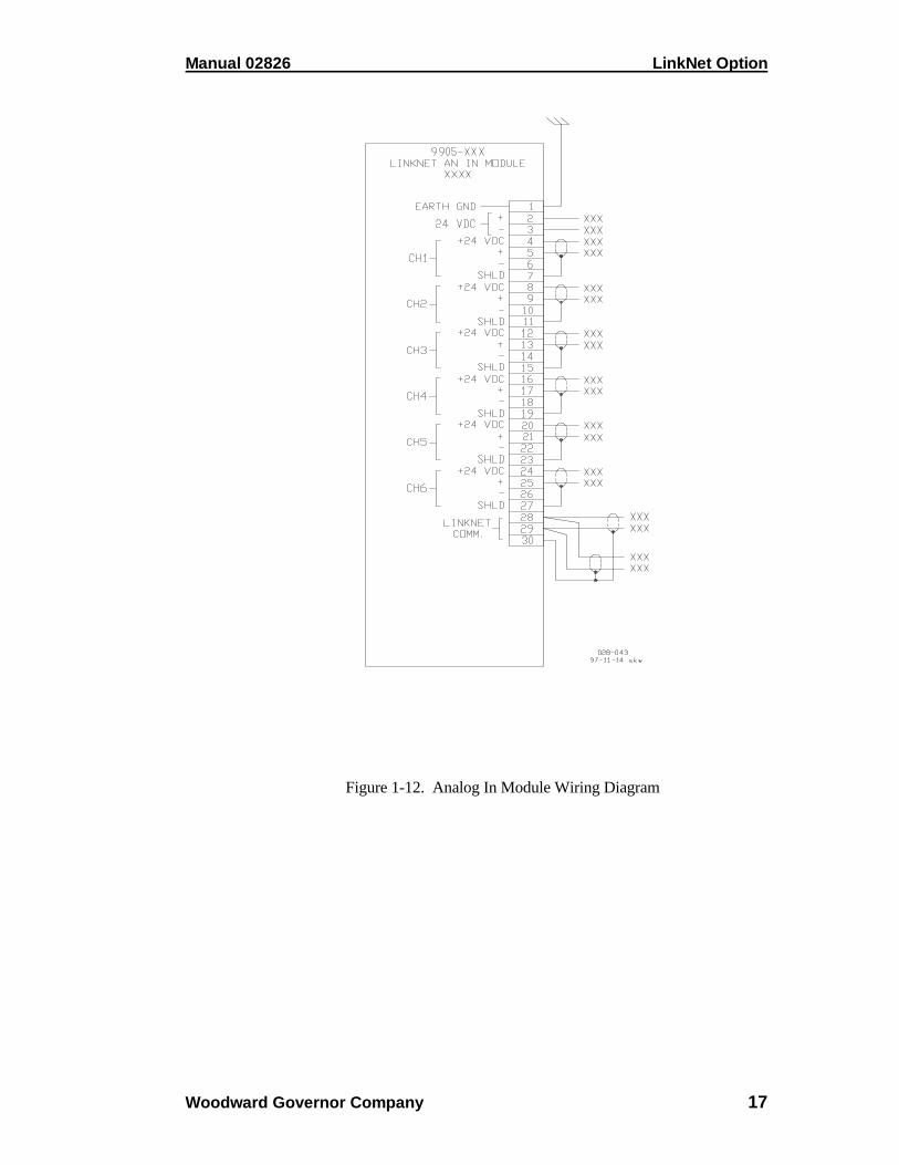
Figure 1-12. Analog In Module Wiring Diagram

LinkNet Option Manual 02826
18 Woodward Governor Company
Figure 1-13. Thermocouple Module Wiring Diagram

Manual 02826 LinkNet Option
Woodward Governor Company 19
Figure 1-14. RTD Module Wiring Diagram
LinkNet Option Manual 02826
20 Woodward Governor Company
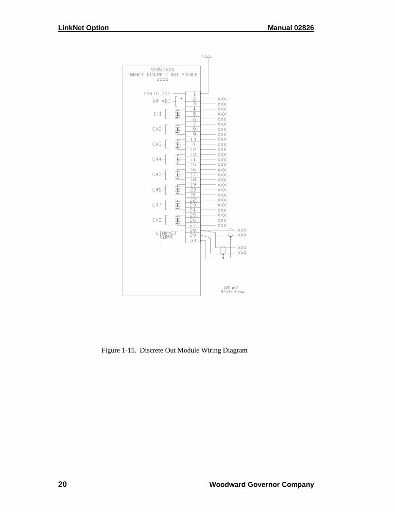
Figure 1-15. Discrete Out Module Wiring Diagram

Manual 02826 LinkNet Option
Woodward Governor Company 21
Figure 1-16. Analog Out Module Wiring Diagram

LinkNet Option Manual 02826
22 Woodward Governor Company

Manual 02826 LinkNet Option
Woodward Governor Company 23
Chapter 2Electrostatic Discharge Awareness
All electronic equipment is static-sensitive, some components more than others. Toprotect these components from static damage, you must take special precautions tominimize or eliminate electrostatic discharges.
Follow these precautions when working with or near the control.
1. Before doing maintenance on the electronic control, discharge the staticelectricity on your body to ground by touching and holding a grounded metalobject (pipes, cabinets, equipment, etc.).
2. Avoid the build-up of static electricity on your body by not wearing clothingmade of synthetic materials. Wear cotton or cotton-blend materials as muchas possible because these do not store static electric charges as much assynthetics.
3. Keep plastic, vinyl, and styrofoam materials (such as plastic or styrofoamcups, cup holders, cigarette packages, cellophane wrappers, vinyl books orfolders, plastic bottles, and plastic ash trays) away from the control, themodules, and the work area as much as possible.
4. Do not remove the printed circuit board (PCB) from the control cabinetunless absolutely necessary. If you must remove the PCB from the controlcabinet, follow these precautions:
• Do not touch any part of the PCB except the edges.
• Do not touch the electrical conductors, the connectors, or thecomponents with conductive devices or with your hands.
• When replacing a PCB, keep the new PCB in the plastic antistaticprotective bag it comes in until you are ready to install it. Immediatelyafter removing the old PCB from the control cabinet, place it in theantistatic protective bag.

LinkNet Option Manual 02826
24 Woodward Governor Company

Manual 02826 LinkNet Option
Woodward Governor Company 25
Chapter 3Service Options
Product Service Options
The following are the factory options available for the service of Woodwardequipment:• Replacement/Exchange (3-year warranty) (24-hour service)• Flat Rate Repair (6-month warranty)• Flat Rate Remanufacture (3-year warranty)
If you are experiencing problems with installation or unsatisfactory performanceof an installed system, the following options are available:• Consult the system troubleshooting guide in this section.• Contact Woodward technical assistance at (800) 835–5182 (in North
America) or at (970) 663–3900 (outside North America) and discuss yourproblem. In most cases, your problem can be resolved over the phone. If not,you can select which course of action you wish to pursue based on theavailable services listed in this section.
Replacement/Exchange
Replacement/Exchange is a premium program designed for the user who is in needof immediate service. It allows the user to request and receive a like-newreplacement unit in minimum time (usually within 24 hours of the request),providing a suitable unit is available at the time of the request, thereby minimizingcostly downtime. This is also a Flat Rate structured program and includes the full3-year warranty.
This option allows customers to call in advance of a scheduled outage or anunexpected outage and request a replacement control unit. If the unit is availableat the time of the call, it can usually be shipped out within 24 hours. The customerreplaces his field control unit with the like-new replacement and returns the fieldunit to the Woodward facility as explained later in this chapter.
Charges for the Replacement/Exchange service are based on a flat rate plusshipping expenses. The customer is invoiced the flat rate charge at the time thereplacement unit is shipped and must return the field unit to Woodward within 30days. If the unit is not received within that time frame, the customer is invoiced thedifference between the flat rate replacement/exchange charge and the current listprice of a new unit.

LinkNet Option Manual 02826
26 Woodward Governor Company
Return Shipment Authorization Label. To ensure prompt receipt of the core,and avoid additional charges, the package must be properly marked. A returnauthorization label is included with every Replacement/Exchange unit that leavesWoodward. The core should be repackaged and the return authorization labelaffixed to the outside of the package. Without the authorization label, receipt ofthe returned core could be delayed and cause additional charges to be applied.
Flat Rate Repair
Flat Rate Repair is available for the majority of standard products in the field.This program offers the user repair service for their products with the advantageof knowing in advance what the cost will be. All repair work carries a 180-daywarranty on replaced parts and labor.
Flat Rate Remanufacture
Flat Rate Remanufacture is very similar to the Flat Rate Repair option with theexception that the unit will be returned to the user in “like new” condition andcarry with it a full 3-year warranty. This option is applicable to mechanicalproducts only.
Returning Equipment for Repair
! WARNINGExplosion Hazard—Do not connect or disconnect while circuit is live,unless area is known to be non-hazardous.
Explosion Hazard—Substitution of components may impair suitab ilityfor Class I, Division 2.
! AVERTISSEMENTRisque d'explosion—Ne pas raccorder ni débrancher tant quel’installation est sous tension, sauf en cas l’ambiance est décidémentnon dangereuse.
Risque d'explosion—La substitution de composants peut rendre cematériel inacceptable pour les emplacements de Classe I, Division 2.

Manual 02826 LinkNet Option
Woodward Governor Company 27
If any part of the electronic control is to be returned to Woodward GovernorCompany for repair, attach a tag to the part with the following information:• name and location where the control is installed;• name and phone number of contact person;• complete Woodward Governor Company part number(s) and serial
number(s);• description of the problem;• instructions describing the desired type of repair.
! CAUTIONTo prevent damage to electronic components caused by improperhandling, read and observe the precautions in W oodward GovernorCompany Manual 82715, Guide for Handling and Protection ofElectronic Controls, Printed Circuit Boards, and Modules .
Packing a Control
Use the following materials when returning a complete control:• protective caps on all connectors;• antistatic protective bags on all electronic modules;• packing materials that will not damage the surface of the unit;• at least 100 mm (4 inches) of tightly packed, industry-approved packing
material;• a packing carton with double walls;• a strong tape around the outside of the carton for increased strength.
Additional Instructions
When returning equipment to Woodward, please telephone and ask for theCustomer Service Department [(800) 835–5182 or (970) 663–3900]. They willhelp expedite the processing of your order through our distributors or local servicefacility. Factory repairs will be greatly expedited if a purchase order has beenissued for the item(s) to be repaired. Make arrangements in advance if possible.
Replacement Parts Information
When ordering replacement parts for electronic controls, include the followinginformation:
• the part number(s) (XXXX-XXX) that is on the enclosure nameplate;• the unit serial number, which is also on the nameplate.

LinkNet Option Manual 02826
28 Woodward Governor Company
How to Contact Woodward
Use the following address when shipping or corresponding:
Woodward Governor CompanyIndustrial Controls GroupPO Box 38003800 North Wilson AveLoveland CO 80539-3800
TELEPHONE: (970) 663-3900 (24 hours a day)TOLL-FREE PHONE (in North America): (800) 835-5182FAX: (970) 962-7050
There is also information and e-mail addresses on Woodward’s Internet (WorldWide Web) home page:
http://www.woodward.com
Other Service Facilities
Contact Woodward Governor Company, Customer Service Department, for thename of your nearest Woodward distributor or service facility.
Additional Aftermarket Product Support Services
Woodward Aftermarket Services offers the following after-sale support for allWoodward products:• Customer Training• Technical Assistance• Field Service• Specialized Services
Customer Training is offered either at our facilities in Loveland and Fort Collins,Colorado, or at the customer’s site. This training, conducted by experiencedtrainers, will assure that customer personnel will be able to maintain systemreliability and availability. For information concerning training available, call thenumber above and ask for customer training.
Technical Assistance is available using the Woodward toll-free number. TheAftermarket application engineering group is available to assist customers withtechnical questions or problem solving during normal business hours (07:00through 15:30 Mountain Time, Monday through Friday, except holidays) or asemergency support 24 hours a day. This group can also provide engineeringsupport for changes or enhancements after the commissioning of your system. Fortechnical engineering assistance, call the number above and ask for technicalassistance.

Manual 02826 LinkNet Option
Woodward Governor Company 29
Field Service engineers are dispatched from the Woodward facility in Colorado,or from one of many regional or worldwide offices located near the customer toprovide prompt response. Woodward field engineers are experienced and arecontinually updated on all Woodward products as well as much of the non-Woodward equipment they interface with. The field engineers ensure that alldocumentation is updated, and all field engineers are well informed as to newproblems which might arise. Woodward field service engineers are on-call 24hours a day. Call the number above and ask for field service.
Specialized Services can be tailored to the specific needs of the customer. Theseservices can be based on a particular aspect of a single service or a combination ofservices and are covered under one low-cost service contract. A contract may befor regularly scheduled training courses or possibly to have a field engineer visitthe customer site at pre-determined intervals to provide a system analysis, verifyproper operation, and make recommendations for maintenance improvements,enhancements, or other needs. These contracts are usually custom-designed andstructured to allow ultimate flexibility, thereby allowing the customer to plan andbudget more accurately. For more details, contact the Woodward salesrepresentative, or call the number above and ask for sales support to discussspecific needs.
For more information on Woodward aftermarket services accesshttp://www.woodward.com on the Internet.
System Troubleshooting Guide
The following is a general troubleshooting guide for areas to check which maypresent potential difficulties. By making these checks before contacting Woodwardfor technical assistance, your system problems can be more quickly and accuratelyassessed.
Actuators• Is the oil clean?• Does the actuator have the correct hydraulic pressure (if required)?• Does the actuator have the correct pneumatic pressure (if required)?• Does the driveshaft rotate (if required)?• Is the actuator wiring correct?• Is the direction of the stroke correct?• Has the compensation (if so equipped) been adjusted correctly?• Is the hydraulic return line free and not clogged?• Is there back pressure on the hydraulic return line?• Is the feedback (if any) adjusted correctly and sending the correct signal?

LinkNet Option Manual 02826
30 Woodward Governor Company
Linkage• Is there slop or lost motion?• Is there misalignment, binding, or side loading?• Is there visible wear or scarring?• Does the linkage move smoothly?
Valves• Does the valve move through it’s proper stroke smoothly?• Does the valve travel it’s full stroke?• Can mid-stroke be obtained and held?• Does the valve fully seat (close) before the governor reaches full minimum
stroke?• Does the valve fully open before the governor reaches maximum stroke?• Is the bypass valve(s) (if any) in the proper position?• Are there nicks or contamination which allow steam to pass when the valve is
closed?
Oil/Hydraulic System• Is the oil at the proper operating pressure?• Is the oil temperature too high for the type of oil being used?• Is the oil contaminated?• Does the actuator have sufficient flow of oil?• Are the accumulators (if any) charged to the correct pressure?• Are the filters plugged?• Is the oil pump operating properly?
Steam Conditions• Is the turbine inlet pressure at design specification?• Is the steam pressure in the proper operating range?• Are pressure transducers (if any) located close to the turbine?• Are there any pressure regulating devices or valves which may interfere with
governor operation or proper steam flow?
Control, Alarm, And Fault Indications• Does the governor indicate it is in the correct control mode?• Is the governor issuing any alarms?• Are any of the components of the governor indicating hardware faults?• Does the actuator demand agree with the actual valve position?• Are any shutdown conditions present?• Have the control dynamics been tuned to match the system response?

Manual 02826 LinkNet Option
Woodward Governor Company 31
Input Signals• Are all input signals properly scaled?• Are the inputs free of electrical noise and properly shielded?• Is the wiring correct?• Have all field input signals to the control been verified?• Is the polarity of the signals correct?
Output Signals• Are the outputs calibrated?• Have the actuator drivers been calibrated to the stroke of the turbine valves?• Are the output signals free of noise and properly shielded?• Is the wiring correct?
Transducers• Is the transducer calibrated for the proper range?• Has it been tested by simulating it’s input and measuring it’s output signal?• Does the transducer have power?• Are the sensing lines feeding the transducer clear of obstructions?
Magnetic Pickups And Other Speed Sensing Devices• Is the wiring between the speed sensing pickup and the control correct?• Are there any grounding problems or worn shields?• Is the signal sufficient (at least 1.5 Vrms)?• Is the signal a clean sine wave or square wave with no spikes or distortions?• Is the MPU head clean and free of oil or metallic particles?• Is the MPU head free of any nicks or chips?• Is the MPU or proximity probe correctly aligned with the gear?• Is the speed sensing probe adjusted to the correct gap?• Is the speed sensing probe head the correct size for the toothed wheel it is
being used with?
Input Voltage/Power Supplies• Is the input power within the range of the control’s power supply input?• Is the input power free of switching noise or transient spikes?• Is the power circuit dedicated to the governor only?• Are the control’s supplies indicating that they are OK?• Are the control’s supplies outputting the correct voltage?

LinkNet Option Manual 02826
32 Woodward Governor Company
Electrical Connections• Are all electrical connections tight and clean?• Are all signal wires shielded?• Are shields continuous from the device to the control?• Are the shields terminated according to Woodward specifications?• Are there low voltage signal wires running in the same wiring trays as high
voltage wiring?• Are the governor’s signal common or grounds not tied to any other devices?• Have the signals been checked for electrical noise?
Voltage Regulator• Is the voltage regulator working properly?
External Devices• Are there external devices the control is dependent on for input signals?• Are these devices providing the correct signal to the control?• Is the external device configured or programmed to be compatible with the
control?

Manual 02826 LinkNet Option
Woodward Governor Company 33
Technical Assistance
If you need to telephone for technical assistance, you will need to provide the following information.Please write it down here before phoning:
GeneralYour Name Site Location Phone Number Fax Number
Prime Mover InformationEngine/Turbine Model Number Manufacturer Number of Cylinders (if applicable) Type of Fuel (gas, gaseous, steam, etc) Rating Application
Governor InformationPlease list all Woodward governors, actuators, and electronic controls in your system:
Woodward Governor Part Number and Revision Letter
Control Description or Governor Type
Serial Number
Woodward Governor Part Number and Revision Letter
Control Description or Governor Type
Serial Number
Woodward Governor Part Number and Revision Letter
Control Description or Governor Type
Serial Number
If you have an electronic or programmable control, please have the adjustment setting positions orthe menu settings written down and with you at the time of the call.

LinkNet Option Manual 02826
34 Woodward Governor Company


![Instituto Nacional de la ViviendaEMPLEADOS+FIJOS+ABRIL++2019..pdf · . / [108] DEPARTAMENTO DE ACCESO A LA INFORMACION PUBLICA 02826 Hilcia Ramona Perez Taveras Encargada Designado](https://img.pdfslide.net/doc/110x75/5f96a55c5c47981ca2639f57/instituto-nacional-de-la-vivienda-empleadosfijosabril2019pdf-108-departamento.jpg)


![Instituto Nacional de la Vivienda · 2020-07-01 · Subtotales Unidad De Legalizacion 3 empleados 98,500.00. / [108] DEPARTAMENTO DE ACCESO A LA INFORMACION PUBLICA 02826 Hilcia Ramona](https://img.pdfslide.net/doc/110x75/5f6fd7c00032406022445ed4/instituto-nacional-de-la-vivienda-2020-07-01-subtotales-unidad-de-legalizacion.jpg)