Embed Size (px)
Citation preview

03 - Ionization chambers
Jaroslav Adam
Czech Technical University in Prague
Version 2
Jaroslav Adam (CTU, Prague) DPD_03, Ionization chambers Version 2 1 / 130

Principle of operation
Charged particle getting through a volume of a gas or noble liquid
Interaction proceed through ionization and end excitation of the molecules, electron-ion pairsare created
Ion can be created directly by the incident particle, or by the δ-electrons, when the energyfrom the primary particle if first transferred to the electron which acquires enough energy tomake further ionization
Electric field is applied by the electrodes, electrons and ions drift to them
If the field is high enough, drifting electrons can also ionize the gas (proportional counters)
After further increase of the field strength, electrons emit UV light on the anode(Geiger-Muller counter)
Electronic signal at the output, pulsed or current regime
Position sensitivity by segmenting one of the electrodes (xy ) and by timing measurement (z)
Jaroslav Adam (CTU, Prague) DPD_03, Ionization chambers Version 2 2 / 130

Ionization detectors without amplification
Jaroslav Adam (CTU, Prague) DPD_03, Ionization chambers Version 2 3 / 130

Number of ion pairs
Minimum energy W to be transferred from the incident particle to create at least one ion pair
Quantified as average energy loss to create the pair
Given by the least tightly bound shell, W = 10 - 25 eV
Non-ionizing energy loss (excitation) makes number of pairs lower
Fully stopped 1 MeV particle produces 30 000 ion pairs
Number of pairs is important for resolution
Jaroslav Adam (CTU, Prague) DPD_03, Ionization chambers Version 2 4 / 130
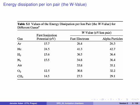
Energy dissipation per ion pair (the W-Value)
Jaroslav Adam (CTU, Prague) DPD_03, Ionization chambers Version 2 5 / 130

Fano factor
Fluctuation in number of pairs affect the energy resolution
The simplest approach postulate Poisson statistics for number of ion pairs (σ =√
N)
Fano factor makes correction to predicted variance to get observed variance
Fano factor = 0 if all incident energy converted into pairs, no statistical fluctuation
In gases Fano factor < 1, Poisson distribution valid but fluctuations are smaller than√
N
Significant in pulse mode
Jaroslav Adam (CTU, Prague) DPD_03, Ionization chambers Version 2 6 / 130

Principle of ionization chamber
Figure : Planar ionization chamber
Suppose two metallic electrodes at distance D covering volume of a gas or noble liquid
Voltage V applied to anode (thousands of kV)
Number of electrons n− given by the number of minimum-ionizing-particles (mip)
n− =nW
DρdEdx
(1)
ρ is the density and dE/dx is energy loss per g cm−2
Jaroslav Adam (CTU, Prague) DPD_03, Ionization chambers Version 2 7 / 130

Charge carriers in gas/liquid volume
Several processes applies to the ion pairs
Drift movement by external electric field
Diffusion due to random thermal movement
Charge transfer
Recombination
Jaroslav Adam (CTU, Prague) DPD_03, Ionization chambers Version 2 8 / 130

Drift movement
Electrostatic force moves the charges, positive ions opposite to electrons and negative ions
Drift of electrons characterized by drift velocity in electric field E = V/D
vd (e) =dxdt
=µe
pE =
Vµe
pD(2)
Electron mobility µe given in unit of bar cm2 V−1 s−1, p is the gas pressure
Mobility of ions is about 1000 less than of electrons
Description with mobility provides calculation of readout times
ms for ions, µs for electrons
Jaroslav Adam (CTU, Prague) DPD_03, Ionization chambers Version 2 9 / 130

Saturation of the drift velocity
Figure : Electron velocity vs. filed
No increase in drift velocity after reaching it’s maximum, only in some gases
Hydrocarbons, argon-hydrocarbon mixtures
In non-saturation gases, E/p proportionality holds up to high fields
Jaroslav Adam (CTU, Prague) DPD_03, Ionization chambers Version 2 10 / 130
Diffusion
Thermal movement with mean free path of about 10−6 - 10−8 m
More important for electrons since their thermal velocity is bigger
Point-like collection of electrons form Gaussian spatial distribution widening with time
Widening in one direction x , y or z given by diffusion coefficient D
σ =√
2Dt (3)
D is given by kinetic gas theory or the process is described by a transport model
Jaroslav Adam (CTU, Prague) DPD_03, Ionization chambers Version 2 11 / 130
Charge transfer collisions
Electron transfer from neutral gas molecule to positive ion in mutual collision
Significant in mixtures, net positive charge transfered to species with lowest ionization energy
Negative ion can be formed by capturing of free electron (oxygen)
Jaroslav Adam (CTU, Prague) DPD_03, Ionization chambers Version 2 12 / 130

Recombination
Free electron captured by positive ion making ordinary neutral atom
Positive and negative ions recombine, most probable compared to electron and ion case
Original charge is lost, no contribution to final signal
Recombination rate given by density of positive and negative species n+ and n− andrecombination coefficient α
dn+
dt=
dn−
dt= −αn+n− (4)
Jaroslav Adam (CTU, Prague) DPD_03, Ionization chambers Version 2 13 / 130

Columnar (initial) recombination
Electron-ion pairs created in column along particle trajectory
Recombination of electron with it’s parent ion
Mainly for heavy ionizing particles (low energy α), minimal for mip
Independent of interaction rate
Recombination may occur with neighboring ion when electrons are drifting in electric field
Depends on the angle between incident particle and electric field
Jaroslav Adam (CTU, Prague) DPD_03, Ionization chambers Version 2 14 / 130
Volume recombination
Recombination during drift towards electrodes
Unlike initial/columnar recombination, this depends on irradiation rate
Suppressed by fast charge separation and collection -> high electric field
Jaroslav Adam (CTU, Prague) DPD_03, Ionization chambers Version 2 15 / 130

Ionization current, DC ion chamber
Constant irradiation rate creates constant formation of ion pairs
Steady-state current is measure of the rate
Supposing negligible recombination and efficient charge collection
Figure : Planar ionization chamber
Jaroslav Adam (CTU, Prague) DPD_03, Ionization chambers Version 2 16 / 130

Current-voltage characteristics
Electric field by external voltage
Current in the circuit equal to ionization current at equilibrium
Increasing voltage begins to separate the charges that would recombine
High electric field makes recombination negligible
After ion saturation, all charges are collected, on increase in current when increasing thevoltage
Standard operation of ion chambers, current in the circuit is an indication of the rate of ionpairs formation
Jaroslav Adam (CTU, Prague) DPD_03, Ionization chambers Version 2 17 / 130

Saturation currentRecombination, especially columnar recombination require high voltage
Volume recombination important at high irradiation intensity
Higher voltage required to get true saturation current
More important in neutron measurement, where heavy fragments are detected
With chambers filled by ambient air, recombination depends on humidity
Jaroslav Adam (CTU, Prague) DPD_03, Ionization chambers Version 2 18 / 130

Perturbations in current due to diffusion
Imbalance in steady-state situation supposing uniform production of ions within the chamber
Larger concentration of positive ions close to cathode, opposite for electrons close to anode
Gradient in concentration formed, diffusion opposite to drift
Perturbation in measured current in planar chamber given by
−∆II
=εkTeV
(5)
ε is ratio of average energy of charge carrier, kT/e ≈ 2.5× 10⁻² V at room temperature
ε close to one for ions, but several hundreds for electrons
Jaroslav Adam (CTU, Prague) DPD_03, Ionization chambers Version 2 19 / 130

Losses of saturation current due to diffusion
ε close to one for ions, but much larger, several hundreds for electrons
Minimized by high voltage
Columnar recombination not fully eliminated
Separate measurements of ionization current as a function of voltage
1/I as a function of 1/V to determine true saturation current
Jaroslav Adam (CTU, Prague) DPD_03, Ionization chambers Version 2 20 / 130

Operation of DC ion chamber
No special requirement on gas since negative charge can be collected as free electrons aswell as negative ions
Only recombination could affect the amount of charge, suppressed by high enough voltage
Few centimeters and tens of hundreds of volts sufficient to reach saturation
Air for gamma-ray exposure, denser gases like Argon to increase ionization density
Pressure about 1 atmosphere, higher to increase sensitivity
Jaroslav Adam (CTU, Prague) DPD_03, Ionization chambers Version 2 21 / 130

Geometry of ionization chamber
Electric field given by geometry of electrodes
Uniform electric field with planar geometry
Cylindrical geometry with electrical field as E(r) =U0
r ln(ra/ri )
Figure : Cylindrical ionization chamber
Jaroslav Adam (CTU, Prague) DPD_03, Ionization chambers Version 2 22 / 130
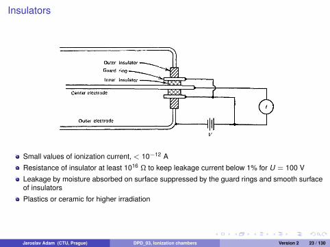
Insulators
Small values of ionization current, < 10−12 A
Resistance of insulator at least 1016 Ω to keep leakage current below 1% for U = 100 V
Leakage by moisture absorbed on surface suppressed by the guard rings and smooth surfaceof insulators
Plastics or ceramic for higher irradiation
Jaroslav Adam (CTU, Prague) DPD_03, Ionization chambers Version 2 23 / 130

Measurement of gamma-ray exposure with ion chambers
Amount of charge in air-filled ionization chamber
Charge is measure of exposure, ionization current gives exposure rate
Requires to measure ionization of all secondary electrons, mean free pairs several meters
compensation for secondary electrons needed
Jaroslav Adam (CTU, Prague) DPD_03, Ionization chambers Version 2 24 / 130

Compensation by free-air ionization chamber
Collimated X-rays, compensation in horizontal direction
Compensation of electrons escaping the sensitive volume by electrons emerging elsewhere
Up to gamma-ray of 100 keV
Jaroslav Adam (CTU, Prague) DPD_03, Ionization chambers Version 2 25 / 130

Air equivalent compensation
Reduces space requirements for higher gamma-rays energies, wall thickness less than 1 cm
Exposure rate given by saturation current Is and mass M in active volume
R =IsM
(6)
Jaroslav Adam (CTU, Prague) DPD_03, Ionization chambers Version 2 26 / 130

DC chambers for radiation survey
Radiation monitoring
Saturation current in closed volume of several cm3
Dose measured by charge integration
Initial charge on the chamber, drop in voltage measures total integrated ionization charge
Jaroslav Adam (CTU, Prague) DPD_03, Ionization chambers Version 2 27 / 130
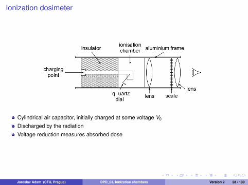
Ionization dosimeter
Cylindrical air capacitor, initially charged at some voltage V0
Discharged by the radiation
Voltage reduction measures absorbed dose
Jaroslav Adam (CTU, Prague) DPD_03, Ionization chambers Version 2 28 / 130

Calibration of radiation source
Saturation current depends only on geometry, long time stability
Current from unknown source compared with standard under same geometry
Chambers with thousands of cm3
Pressured gas for higher sensitivity
Jaroslav Adam (CTU, Prague) DPD_03, Ionization chambers Version 2 29 / 130

Geometry for calibration of gamma-ray sources
Calibration for gamma-ray sources, ionization current for small displacement of the source
Jaroslav Adam (CTU, Prague) DPD_03, Ionization chambers Version 2 30 / 130

Measurement of radioactive gases
Radioactive gas as constituent of fill gas, sampled as continuous flow
Ionization current I given by average energy deposition per gas disintegration E and totalactivity α
I =EαeW
(7)
Principle of smoke detectors where ionization current from internal alpha source decreasesdue to presence of the smoke in sampled air
Jaroslav Adam (CTU, Prague) DPD_03, Ionization chambers Version 2 31 / 130

Remote sensing of ionization
Positive and negative ions in the air survive for minutes before recombination
Flow of air is transported to a chamber outside the source of radiation
LRAD - Long Range Alpha Detector:
Sample of alpha-contaminated material in container, air flowing though it
Positive and negative ions carried into an ion chamber
Jaroslav Adam (CTU, Prague) DPD_03, Ionization chambers Version 2 32 / 130

Pulse mode operation
Each radiation quantum provides with distinguishable signal pulse
Application in radiation spectroscopy
Alpha spectrometry
Neutron detection
Jaroslav Adam (CTU, Prague) DPD_03, Ionization chambers Version 2 33 / 130

Equivalent circuit of ion chamber
Chamber is represented by it’s capacity C
Voltage V0 on load resistor R
Drifting charges from ionization create induced charge on electrodes
Voltage drops from equilibrium V0, giving output pulse VR
Slow return to equilibrium according time constant RC
If RC > time to collect all charges, amplitude of the pulse measures the original charge
Jaroslav Adam (CTU, Prague) DPD_03, Ionization chambers Version 2 34 / 130

Equivalent circuit of ion chamber
The ion chamber behaves as parallel connection of resistor and capacity, called RC circuit
Time dependence of voltage V given bycapacity C and resistivity R
CdVdt
= I =VR
(8)
Response to initial charge giving voltage V0is
V (t) = V0e−t/RC (9)
Jaroslav Adam (CTU, Prague) DPD_03, Ionization chambers Version 2 35 / 130
Electron sensitive mode
Time to collect electrons ∼ µs, time for ions ∼ ms
Collection of all charges would require RC of orders of >ms
This would mean low pulse rate only and interference from microphonic signals
For electron sensitivity, RC between electron and ion collection time
Negative ions no longer allowed
Jaroslav Adam (CTU, Prague) DPD_03, Ionization chambers Version 2 36 / 130

Pulse shape in planar chamber
Constant electric field E = V/d
Uniform equipotentials parallel to electrode surfaces
Ions supposed to be formed at equal distance x where electric potential is Ex
Jaroslav Adam (CTU, Prague) DPD_03, Ionization chambers Version 2 37 / 130
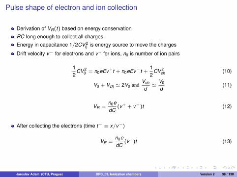
Pulse shape of electron and ion collection
Derivation of VR(t) based on energy conservation
RC long enough to collect all charges
Energy in capacitance 1/2CV 20 is energy source to move the charges
Drift velocity v− for electrons and v+ for ions, n0 is number of ion pairs
12
CV 20 = n0eEv+t + n0eEv−t +
12
CV 2ch (10)
V0 + Vch ' 2V0 andVch
d'
V0
d(11)
VR =n0edC
(v+ + v−)t (12)
After collecting the electrons (time t− ≡ x/v−)
VR =n0edC
(v+)t (13)
Jaroslav Adam (CTU, Prague) DPD_03, Ionization chambers Version 2 38 / 130

Pulse shape of electron and ion collection
After collecting the ions (time t+ ≡ (d − x)/v+)
VR =n0edC
[(d − x) + x ] (14)
VR =n0eC
(15)
If RC t+, maximum amplitude of the pulse is
Vmax =n0eC
(16)
Independent of position of incident ionization
Jaroslav Adam (CTU, Prague) DPD_03, Ionization chambers Version 2 39 / 130

Pulse shape of electron and ion collection
Jaroslav Adam (CTU, Prague) DPD_03, Ionization chambers Version 2 40 / 130

Pulse shape in electron sensitive operation
Pulse shape given by electrons
Amplitude sensitive to position of incident radiation
V |elec =n0eC·
xd
(17)
Monoenergetic radiation produces a range of pulses
Removed by dividing the ion chamber by adding a grid
Jaroslav Adam (CTU, Prague) DPD_03, Ionization chambers Version 2 41 / 130

Gridded ion chamber
Designed to remove amplitude position dependency
All interactions between the grid (Frisch grid) and the cathode
Grid at intermediate potential and transparent for electrons
Grid-anode voltage drops after electrons pass through the grid
Jaroslav Adam (CTU, Prague) DPD_03, Ionization chambers Version 2 42 / 130

Electron signal in gridded ion chamber
Jaroslav Adam (CTU, Prague) DPD_03, Ionization chambers Version 2 43 / 130

Electron signal in gridded ion chamber
With RC larger than electron collection time and grid-anode spacing d , signal on load resistoris
VR =n0edC
v−t (18)
Maximum voltage is
Vmax =n0eC
(19)
Allows to operate at short RC
Pulse independent of position of incident radiation
But signals of order of < 10−5 V
Can not be measured directly, amplification needed
Jaroslav Adam (CTU, Prague) DPD_03, Ionization chambers Version 2 44 / 130

Statistical limit to energy resolution
Number of charges n0 and fano factor F gives statistical limit
Supposing fully stopped α at energy E = 5.5 MeV in gas with W = 30 eV/ion pair andF = 0.15
n0 =Ed
W= 1.83× 10⁵ ion pairs (20)
Standard deviation as square root of variance
σn0 =√
Fn0 = 166 (21)
Jaroslav Adam (CTU, Prague) DPD_03, Ionization chambers Version 2 45 / 130

Statistical limit to energy resolution
FWHM of Gaussian distribution for n0 and particle energy
FWHM(n0) = 2.35σn0 = 390 (22)
FWHM(E) = 2.35σn0 ·W = 11.7 keV (23)
Relative energy resolution to the deposited energy
R =2.35σn0 W
Ed= 0.123% (24)
Good theoretical resolution can not be achieved due to electronic noise
Jaroslav Adam (CTU, Prague) DPD_03, Ionization chambers Version 2 46 / 130

Charged particle spectroscopy with pulse-type ion chamber
Some advantages vs. semiconductor or scintillator detectors
Arbitrary size and geometry
Gas dielectric cable 3500 m long was used as a beam-loss monitor at SLAC
Gas pressure to adjust stopping power or effective thickness
Radiation resistant, simple design
Low level alpha particles, cross sectional area 500 cm2
Bragg curve spectroscopy: analysis of pulse shape from incident particle parallel to the field,can distinguish particle species
Jaroslav Adam (CTU, Prague) DPD_03, Ionization chambers Version 2 47 / 130

Alpha spectroscopy with ionization chamber
Fisch grid ionization chamber filled by argon allows to separate two uranium isotopes
Jaroslav Adam (CTU, Prague) DPD_03, Ionization chambers Version 2 48 / 130

Proportional counters
Jaroslav Adam (CTU, Prague) DPD_03, Ionization chambers Version 2 49 / 130

Charge multiplication in the gas
Late 1940s, effect of gas multiplication
More ion pairs compared to ionization chamber
Low energy X-rays
Neutron detection
Pulse mode most common operation
Jaroslav Adam (CTU, Prague) DPD_03, Ionization chambers Version 2 50 / 130

Avalanche formation
Kinetic energy of the electron sufficient to make secondary ionization
Field at least 106 V m−1
Gas multiplication: secondary electrons also ionize after acceleration
Townsend avalanche
dnn
= αdx (25)
α is the first Townsend coefficient of the gas
Depends on electric field
For constant field (parallel plate geometry), solution is exponential increase in electrondensity:
n(x) = n(0) exp(αx) (26)
Jaroslav Adam (CTU, Prague) DPD_03, Ionization chambers Version 2 51 / 130

Townsend coefficient vs. field
Jaroslav Adam (CTU, Prague) DPD_03, Ionization chambers Version 2 52 / 130

Regions of operation
Jaroslav Adam (CTU, Prague) DPD_03, Ionization chambers Version 2 53 / 130

Cylindrical geometry
Field with anode wire radius a, cathode inner radius b and applied voltage V is
E(r) =V
r ln(b/a)(27)
Jaroslav Adam (CTU, Prague) DPD_03, Ionization chambers Version 2 54 / 130

Field as a function of radius
Jaroslav Adam (CTU, Prague) DPD_03, Ionization chambers Version 2 55 / 130

Avalanche from a single electron, MC transport model
Jaroslav Adam (CTU, Prague) DPD_03, Ionization chambers Version 2 56 / 130

Simulation of avalanche
Winkler et al. Am. J. Phys., Vol. 83, 733-740 (2015)
Jaroslav Adam (CTU, Prague) DPD_03, Ionization chambers Version 2 57 / 130

Development of the avalanche
Jaroslav Adam (CTU, Prague) DPD_03, Ionization chambers Version 2 58 / 130

Construction design
Figure : Cross sectional view, dimensions in cm
Jaroslav Adam (CTU, Prague) DPD_03, Ionization chambers Version 2 59 / 130

Beverage can design, Winkler et al. Am. J. Phys., Vol. 83, 733-740(2015)
Jaroslav Adam (CTU, Prague) DPD_03, Ionization chambers Version 2 60 / 130

2π proportional counter
Jaroslav Adam (CTU, Prague) DPD_03, Ionization chambers Version 2 61 / 130

4π proportional counter
Jaroslav Adam (CTU, Prague) DPD_03, Ionization chambers Version 2 62 / 130
Fill gas
Gases without significant electron attachment
Oxygen or electronegative impurities must be removed in flow-counters
Sealed counters more convenient to use, but may have limited lifetime
Polyatomic gas (methane) to prevent photon-induced effects, component called quench gas
Most common proportional gas is 90% argon + 10% methane (P-10 gas)
Penning effect - component with ionization energy lower than excitation energy of principalgas
Jaroslav Adam (CTU, Prague) DPD_03, Ionization chambers Version 2 63 / 130

Quenching in proportional detectors
Jaroslav Adam (CTU, Prague) DPD_03, Ionization chambers Version 2 64 / 130

Gas multiplication factor
Single electron response by avalanche created by one electron outside multiplication region
Total charge by n0 original pairs with gas multiplication factor M is
Q = n0eM (28)
In cylindrical geometry, Townsend coefficient α depends on the radius (and on the field)
ln M =
∫ rc
adrα(r) (29)
α is higher closer to the anode where the field is stronger
Parametrizations of α on the field use experimental data
Jaroslav Adam (CTU, Prague) DPD_03, Ionization chambers Version 2 65 / 130

Gas multiplication factor vs. voltage
Jaroslav Adam (CTU, Prague) DPD_03, Ionization chambers Version 2 66 / 130

Space charge effects
Reduction of the field near anode due to positive ions
Self induced effects resulting from high gas gain, does not depend on pulse rate
General space charge effect is cumulative for different avalanches, also for lower gain
M should just satisfy signal-to-noise requirement to prevent space charge effects
Simple check by varying the voltage and looking for suppression of large pulse amplitudes
Jaroslav Adam (CTU, Prague) DPD_03, Ionization chambers Version 2 67 / 130

Energy resolution
Fluctuations in n0 and in multiplication
Variance of pulse amplitude given by ion pair fluctuation and single-electron multiplicationvariations
Furry distribution of number of electrons in a given avalanche, probability of ionizationdepends only on E
Polya distribution for higher fields, ionization depends on electron’s history, not only on E
Distribution of pulse amplitude approaches Gaussian for large n0 (more than 20)
Jaroslav Adam (CTU, Prague) DPD_03, Ionization chambers Version 2 68 / 130

Energy resolution
Low energy photons have resolution close to statistical limit
Fractional standard deviation of the peak (FWHM/2.35), P-10 gas at 1 atm pressure
Open circles: standard tungsten anode
Full circles: improved uniformity
Jaroslav Adam (CTU, Prague) DPD_03, Ionization chambers Version 2 69 / 130

Systematic variations in gas multiplication factor
Jaroslav Adam (CTU, Prague) DPD_03, Ionization chambers Version 2 70 / 130

Time characteristics of the signal pulseOutput pulse is sum of drift time of free electrons to reach multiplication region andmultiplication time required for the avanlacheDrift time greater than multiplication time
Jaroslav Adam (CTU, Prague) DPD_03, Ionization chambers Version 2 71 / 130

Equivalent circuit of proportional counter seen by developing signal
Derivation of pulse shape utilizes energy conservation of charge moving across the capacitor
Most of the pulse amplitude from positive ion drift
Collection time of all ions long, hundreds ms, but large fraction of signal developed early ofion drift, fraction of µs
Spread in electron drift times (ionizations along radius) makes spread in rise time of outputpulse
Jaroslav Adam (CTU, Prague) DPD_03, Ionization chambers Version 2 72 / 130

Time development of output pulse
Solid curve represents initial ionization at fixed radius (constant drift time)
Dashed line is for uniform ionization along the radius
Rise time minimized by high electric field in drift region and gases with high electron driftvelocity
Jaroslav Adam (CTU, Prague) DPD_03, Ionization chambers Version 2 73 / 130

Shaping of the output pulse
Pulse shape with different time constants
T is total drift time of positive ions from anode to cathode
Sauli, Principles of operation of multiwire proportional and drift chambers, CERN 77-09 (1977)
Jaroslav Adam (CTU, Prague) DPD_03, Ionization chambers Version 2 74 / 130

Electron drift velocity
Jaroslav Adam (CTU, Prague) DPD_03, Ionization chambers Version 2 75 / 130

Variations of pulse rise time
Pulse shaping with short time constant removes slow component of rise time
Amplitude less than of full collection, effect of balistic deficit
Shape of pulse would vary with radial position of original ion pairs
Minimized by shaping time larger than variation in rise time
Can be used to separate signal α events from electron background
Jaroslav Adam (CTU, Prague) DPD_03, Ionization chambers Version 2 76 / 130

Spurious pulses
Satellite afterpulses from secondary processes following desired signal
Removed by amplitude discrimination since correspond to single-electron avalanche
Effect increases with high value of gas multiplication
Optical photons by excited atoms within the avalanche, low energy electron at cathodesurface through photoeffect
Jaroslav Adam (CTU, Prague) DPD_03, Ionization chambers Version 2 77 / 130

Operating voltage
Signal pulse for every particle with enough energy deposit
Sensitivity to more than one avalanche to suppress space charge effects and spurious pulses
Lower values of multiplication factor, some number of original ion pairs to create detectablesignal
Counting curve to select appropriate operating voltage (counting rate vs. voltage at samesource condition), looking for flat region
Jaroslav Adam (CTU, Prague) DPD_03, Ionization chambers Version 2 78 / 130

Alpha counting
Monoenergetic charged particles of range less than dimensions of the chamber
Jaroslav Adam (CTU, Prague) DPD_03, Ionization chambers Version 2 79 / 130

Beta counting
Range greater than chamber dimensions, smaller pulses compared to alpha
4π counter for absolute beta activity
Greater range advantage for mechanical source backing in 4π counter
Jaroslav Adam (CTU, Prague) DPD_03, Ionization chambers Version 2 80 / 130

Mixed alpha and beta sources
Two readout channels for alpha and beta
Separation by amplitude
Background from cosmic rays or ambient gamma (most sources) does not affect alphawindow
Jaroslav Adam (CTU, Prague) DPD_03, Ionization chambers Version 2 81 / 130

X-ray and gamma-ray sources
Fraction of incident photons absorbed in 5.08 cm of proportional gases at 1 atm pressure
Full absorption of low energy X-ray photons, full energy peaks in pulse spectrum
Small signal (∼ keV photons, W = 25− 35 eV) enhanced by internal gas multiplication
Jaroslav Adam (CTU, Prague) DPD_03, Ionization chambers Version 2 82 / 130

Response function for low-energy X-rays
Characteristic X-rays after photoabsorption of primary radiation may escape withoutinteraction
Suppressed with K-shell energy above incident X-ray energy
Requirements to entrance window, beryllium or aluminum 50 - 250 µm
Jaroslav Adam (CTU, Prague) DPD_03, Ionization chambers Version 2 83 / 130

Fluorescence gating
Electronic separation of photoelectric absorption of incident photon and absorption ofconsequent characteristic X-ray
Proportional counter as series of independent cells, X-ray absorbed in different cell
Two pulses in time coincidence corresponding to full absorption, escape peak avoided
Jaroslav Adam (CTU, Prague) DPD_03, Ionization chambers Version 2 84 / 130

Parallel plate avalanche counters
Heavy charged particles which would impose radiation damage to solid state detectors
Parallel plate electrodes, proportional gas at low pressure
Particle species separation by specific energy loss
For gap of 1 mm, fast component from electrons in ns with high field, time resolution 160 ps
Jaroslav Adam (CTU, Prague) DPD_03, Ionization chambers Version 2 85 / 130

Position-sensitive proportional counters
Avalanche occurs around small portion of anode wire length
Position of avalanche is indicator of axial position in cylindrical geometry
Jaroslav Adam (CTU, Prague) DPD_03, Ionization chambers Version 2 86 / 130

Charge division method
Anode with significant resistance per unit length
Two amplifiers at the ends, sum related to conventional pulse, proportion to the position of theinteraction
Alternatively relative rise time could be analyzed, longer rise time for pulse far from amplifier
Jaroslav Adam (CTU, Prague) DPD_03, Ionization chambers Version 2 87 / 130

Multiwire proportional counters (MWPC)
Cathode plates and anode wires positive vs. cathode
Electrons are collected at one of the wires, avalanche at a particular wire
Large negative pulse at anode where avalanche was collected, smaller positive pulses atneighboring anodes
Jaroslav Adam (CTU, Prague) DPD_03, Ionization chambers Version 2 88 / 130

Electric field lines in MWPC
Field by equidistant grid of anode wires between two parallel cathode plates
High field region only in immediate vicinity of the anodes
Jaroslav Adam (CTU, Prague) DPD_03, Ionization chambers Version 2 89 / 130

Enlarged view of the field around the anode wires in MWPC
Wire spacing 2 mm, wire diameter 20 µm
Sauli, Principles of operation of multiwire proportional and drift chambers, CERN 77-09 (1977)
Jaroslav Adam (CTU, Prague) DPD_03, Ionization chambers Version 2 90 / 130

Readout of MWPC
Each wire is connected to preamp and processed independently
Theoretical position resolution is spacing/√
12, but with pulse amplitude for each wire aroundtrajectory of the particle, it’s possible to reconstruct centre-of-gravity and improve theresolution
Jaroslav Adam (CTU, Prague) DPD_03, Ionization chambers Version 2 91 / 130

Two-dimensional MWPC
Cathodes divided into perpendicular strips
Centroid of discharge located by center-of-gravity technique
Jaroslav Adam (CTU, Prague) DPD_03, Ionization chambers Version 2 92 / 130

Multicell proportional counter
Cylindrical independent cellsCoincidence measurement for process selection or background rejectionJaroslav Adam (CTU, Prague) DPD_03, Ionization chambers Version 2 93 / 130

Microstrip gas chamber (MSGC)
Narrow anode metallic strips (10 µm) on substrate
Quick collection of ions, clearing the space charge
Jaroslav Adam (CTU, Prague) DPD_03, Ionization chambers Version 2 94 / 130

Two-dimensional MSGC
Ionization in fill gas between anodes and drift plane, avalanches by electrons close to anode
Most of signal generated by drift of positive ions away from the anode
Jaroslav Adam (CTU, Prague) DPD_03, Ionization chambers Version 2 95 / 130
Gas electron multiplier (GEM)
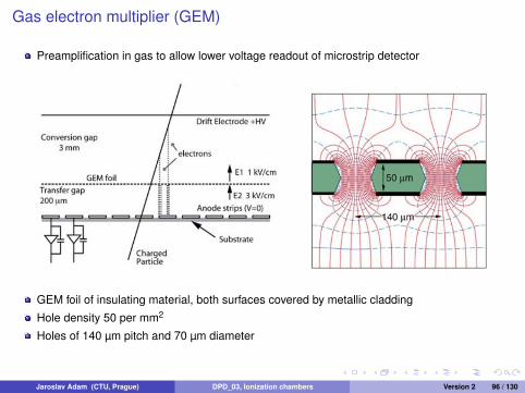
Preamplification in gas to allow lower voltage readout of microstrip detector
GEM foil of insulating material, both surfaces covered by metallic cladding
Hole density 50 per mm2
Holes of 140 µm pitch and 70 µm diameter
Jaroslav Adam (CTU, Prague) DPD_03, Ionization chambers Version 2 96 / 130

GEM foil
Insulating material, both surfaces covered by metallic cladding
Jaroslav Adam (CTU, Prague) DPD_03, Ionization chambers Version 2 97 / 130

Simulation of GEM
Light lines - electrons, dark lines - ions, spots - ionization occurence
Jaroslav Adam (CTU, Prague) DPD_03, Ionization chambers Version 2 98 / 130

Cascade of GEM foils
Gain up to 104 - 105, sensitivity to single electron
Jaroslav Adam (CTU, Prague) DPD_03, Ionization chambers Version 2 99 / 130

Micromegas (micro-mesh gaseous structure)
Two-stage parallel plate avalanche chamber
Ionization above the mesh which is transparent to electrons
Amplification below the mesh in a high field
Avalanche ions collected by the mesh, fast clearing of the space charge
Jaroslav Adam (CTU, Prague) DPD_03, Ionization chambers Version 2 100 / 130

Resistive Plate Chamber (RPC)
Thin gas volume between electrodes of high electrical resistivity
Jaroslav Adam (CTU, Prague) DPD_03, Ionization chambers Version 2 101 / 130

Construction of RPC
Spacers between plates each 10 cm against electrostatic attraction (constant gap size)
Jaroslav Adam (CTU, Prague) DPD_03, Ionization chambers Version 2 102 / 130

Readout of position sensitive RPC
Capacitive coupling of strips to preamps
Jaroslav Adam (CTU, Prague) DPD_03, Ionization chambers Version 2 103 / 130

Time Projection Chamber (TPC) of the ALICE experiment
3D position and dE/dx using volume of 90 m3 of Ne/CO2/N2 (90/10/5) divided into twosectors of 2.5 m
Voltage 100 kV on central electrode, drift field 400 V m−1
Electron drift velocity 2.7 cm µs−1, maximum drift time 92 µs
Readout by MWPC with cathode pad readout mounted in trapezoidal sectors at each endplate, active area of 32.5 m2
Jaroslav Adam (CTU, Prague) DPD_03, Ionization chambers Version 2 104 / 130

MWPC readout of ALICE TPC, cross sectional view along the wires
Grid of anode wires above pad plane, cathode wire plane and gating grid
Wire geometry and pad size dependent on radial track density, 560 000 readout pads
Anode to cathode distance 2 and 3 mm, gain up to 20 000
Gate opens for electrons from the drift volume by the collision trigger (6.5 µs after thecollision) for the duration of drift time, 92 µs, prevents the space charge of positive ions fromdrifting back from multiplication region
Jaroslav Adam (CTU, Prague) DPD_03, Ionization chambers Version 2 105 / 130

MWPC readout, cross sectional view perpendicular to the wires
Jaroslav Adam (CTU, Prague) DPD_03, Ionization chambers Version 2 106 / 130

Particle identification by dE/dx in TPC
Simultaneous measurement of ionization losses and momentumParametrization of Bethe-Bloch formula for several particle species
Jaroslav Adam (CTU, Prague) DPD_03, Ionization chambers Version 2 107 / 130

Upgrade of TPC
Expected rate 50 kHz of Pb-Pb, 5 interactions within maximal electron drift time, 10 eventssuperimposed from past+future time window
Untriggered readout without use of gating grid
Readout by GEM foils instead of MWPC, field 50 kV/cm in the hole
Suppression of back flowing ions
One side segmented to reduce total charge on the foil, segments coupled by resistors
Jaroslav Adam (CTU, Prague) DPD_03, Ionization chambers Version 2 108 / 130
Geiger-Mueller Counters
Jaroslav Adam (CTU, Prague) DPD_03, Ionization chambers Version 2 109 / 130

G-M counter
Introduced in 1928, one of the oldest detectors
Higher field than in proportional counter
One avalanche can create at least one another avalanche, chain reaction
All pulses have same amplitude, 109 - 1010 ion pairs
Pulse amplitude in volts, no need for external amplification
Counting rate limited by dead time
Jaroslav Adam (CTU, Prague) DPD_03, Ionization chambers Version 2 110 / 130

Geiger discharge
Excited molecules of neutral gas in Townsend avalanche, together with positive ions
They emit visible or UV light, may be absorbed by photoeffect at any place of the tube, newfree electron created
Or free electron created by absorption at cathode
New avalanche from the free electron after reaching the multiplication region around anode
Subcritical proportional tube: n′0p 1 with n′0 number of excited molecules in typicalavalanche and p the probability of photoabsorption
Geiger discharge with single avalanche multiplication 106 - 100 has n′0 bigger, criticalityachieved as n′0p ≥ 1
Jaroslav Adam (CTU, Prague) DPD_03, Ionization chambers Version 2 111 / 130

G-M region
Jaroslav Adam (CTU, Prague) DPD_03, Ionization chambers Version 2 112 / 130

Geiger discharge propagation
New avalanches created close to the original one, new electrons have to reach anode region
Spread of Geiger discharge along the anode wire with propagation velocity 2− 4 cm µs−1
over entire length of anode, few µs after initiating event
Avalanches at random positions around anode, electrons collected by anode, secondarypositive ions around the multiplication region
Field reduced by space charge of the ions, multiplication reduced, Geiger dischargeterminated
Amount of needed space charge independent of initial ionization, the reason for same pulseamplitude
Jaroslav Adam (CTU, Prague) DPD_03, Ionization chambers Version 2 113 / 130

Amplitude of Geiger discharge
Amplitude increases with higher applied voltage
More space charge needed to reduce the field below criticality
Overvoltage defined as voltage above minimum required for Geiger discharge initiation
Jaroslav Adam (CTU, Prague) DPD_03, Ionization chambers Version 2 114 / 130

Fill gases
Same requirements as for proportional counters since charge multiplication is needed (nonegative ions...)
Noble gases, helium, argon, quenching component
n′0 increases with E/p (electric field to gas pressure), G-M as sealed tube with pressure lessthan atmospheric
Voltage 500 - 2000 V for anode of 0.1 mm diameter
Jaroslav Adam (CTU, Prague) DPD_03, Ionization chambers Version 2 115 / 130
Quenching
Slow drift of positive ions after Geiger discharge termination to the cathode, neutralizationwith electron from cathode surface
Energy needed = sum of gas ionization energy and energy to extract the electron fromcathode (work function)
If (gas ionization energy) = 2 × (work function), another free electron emerges from thecathode surface
At least one free electron from cathode with large amount of positive ions
Will drift towards anode to make new Geiger discharge
Cycle would repeat, continues output of multiple pulses
No problem for proportional counters, number of ions smaller, only spurious pulses
Jaroslav Adam (CTU, Prague) DPD_03, Ionization chambers Version 2 116 / 130

External quenching
Needed any method to prevent excessive multiple pulsing
Reduction of high applied voltage for some fixed time after the pulse below gas multiplication
Time greater than transit of positive ions to the cathode (hundreds of ms) and transit time offree electron (few µs)
Value of R selected high enough (108 Ω), so RC is of ms
Several ms for anode to return to nominal operating voltage, low counting rate
Jaroslav Adam (CTU, Prague) DPD_03, Ionization chambers Version 2 117 / 130

Internal quenching
Component of quench gas added to primary fill gas, concentration 5 - 10 %
Smaller ionization potential, more complex molecular structure
Multiple pulsing prevented by charge transfer collisions, positive charge of primary gas iontransfered to quench gas molecule, original ion neutralized before reaching cathode
Ions of quench gas at cathode with some concentration of quench component
At cathode, the excess energy dissociates the more complex molecule, emission of freeelectron suppressed, no additional avalanches
Organic molecules, ethyl alcohol, ethyl formate
Limit of 109 counts due to consumption of quench gas
Problem avoided by halogens as quench gas (chorine, bromine), spontaneous recombinationafter dissociation
Limit to lifetime then by contamination of reaction products from the discharge and polymerdeposition on anode surface
Jaroslav Adam (CTU, Prague) DPD_03, Ionization chambers Version 2 118 / 130

Shape of the output pulse
Signal of multiple avalanches from secondary electronsSpread in time for them to reach multiplication regionRise time of few µsElectric field distorted from the space charge of positive ionsFast rise and slow rise from ions drift, time constant less than 100 µs to eliminate slowcomponentLoss in amplitude tolerated due to large amount of chargeDelay in response by drift of original electrons to multiplying region, applies for timing withG-M as time uncertainty
Jaroslav Adam (CTU, Prague) DPD_03, Ionization chambers Version 2 119 / 130

Dead time
Drift of positive ions outwards, recovery of field in multiplying regionAfter drift to some distance, the field permits new Geiger discharge, lower intensity in thebeginningFirst pulses reduced in amplitudeFull field and full amplitude after all ions neutralized at the cathodeDead time = time between initial pulse and second Geiger discharge, regardless of themagnitude, 50 - 100 µsResolving time = time for pulse of amplitude high enough to be registered, dead time mayinclude also recovery time in practical applicationRecovery time = time to return to the original state, pulse of full amplitude
Jaroslav Adam (CTU, Prague) DPD_03, Ionization chambers Version 2 120 / 130

Dead time behavior
Jaroslav Adam (CTU, Prague) DPD_03, Ionization chambers Version 2 121 / 130

Geiger counting plateau
Dependence of measured counting rate on voltage with constant rate from radiation source
Counter threshold Hd , no pulses if amplitude is below
Jaroslav Adam (CTU, Prague) DPD_03, Ionization chambers Version 2 122 / 130
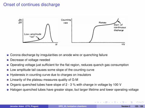
Onset of continues discharge
Corona discharge by irregularities on anode wire or quenching failure
Decrease of voltage needed
Operating voltage just sufficient for the flat region, reduces quench gas consumption
Low amplitude tail causes some slope of the counting curve
Hysteresis in counting curve due to charges on insulators
Linearity of the plateau measures quality of G-M
Organic quenched tubes have slope of 2 - 3 % with change in voltage by 100 V
Halogen quenched tubes have greater slope, but larger lifetime and lower operating voltage
Jaroslav Adam (CTU, Prague) DPD_03, Ionization chambers Version 2 123 / 130

End-window Geiger tube
Fine anode wire, less requirements on uniformity of the wire and of the electric field
Cylindrical cathode of metal or glass with metallized inner surface
Thin window for short-range particles, differential pressure
More robust window for beta or gamma
Jaroslav Adam (CTU, Prague) DPD_03, Ionization chambers Version 2 124 / 130

Other design of Geiger tube
Wire loop anode in cathode of arbitrary volume
Needle counters - sharply pointed needle, field as 1/r2 (1/r for cylindrical geometry), usedfor smaller active volume
Source in counting volume for low-energy particles14C detection by gas mixture of CO2 with counter gas for high counting efficiency
Jaroslav Adam (CTU, Prague) DPD_03, Ionization chambers Version 2 125 / 130

Counting electronics
R is load resistance for signal development
Cs is capacitance of the tube and wiring, parallel with R
RCs ∼ few µs for fast-rising component
Coupling capacitor Cc to block high voltage on the tube, only signal pulse transmitted, RCclarger than pulse duration
Jaroslav Adam (CTU, Prague) DPD_03, Ionization chambers Version 2 126 / 130

Counting efficiency for charged particles
100 % for any charged particle entering the active volume since a single ion pair triggers fullGeiger discharge
Effective efficiency given by the window of the tube, absorption or backscattering
For alpha counting window with 1.5 mg/cm2
Jaroslav Adam (CTU, Prague) DPD_03, Ionization chambers Version 2 127 / 130

Efficiency for neutrons
Rare application for neutron detection
Low capture cross section for Geiger gases
Gamma-ray discrimination not possible, all pulses have same size
Neutron-induced reactions detected by proportional counters, large amplitude from suchreactions
Jaroslav Adam (CTU, Prague) DPD_03, Ionization chambers Version 2 128 / 130

Counting efficiency for gamma rays
Interaction in solid wall of the counter, secondary electron needs just to emerge into activevolume1 - 2 mm of innermost layer of the wallEfficiency increased with high-Z material of the cathode (bismuth Z = 83)Low-energy gamma may interact with fill gas, xenon and krypton (high-Z) enhance theefficiency up to 100 % for photon energies 10 keV
Jaroslav Adam (CTU, Prague) DPD_03, Ionization chambers Version 2 129 / 130

Counting efficiency for gamma rays
Jaroslav Adam (CTU, Prague) DPD_03, Ionization chambers Version 2 130 / 130


![Ionization chambers Proportional counters Geiger Muller counterssleoni/TEACHING/Nuc-Phys-Det/PDF/... · 2014-10-21 · Gas Detectors [the oldest detectors] ! Ionization chambers !](https://img.pdfslide.net/doc/110x75/5eb629c512a9904888072f04/ionization-chambers-proportional-counters-geiger-muller-sleoniteachingnuc-phys-detpdf.jpg)


![Ionization chambers Proportional counters Geiger …sleoni/TEACHING/Nuc-Phys-Det/PDF/Lezione...Gas Detectors [the oldest detectors] ! Ionization chambers ! Proportional counters !](https://img.pdfslide.net/doc/110x75/5b3c112f7f8b9a986e8cc4dc/ionization-chambers-proportional-counters-geiger-sleoniteachingnuc-phys-detpdflezionegas.jpg)