Embed Size (px)
Citation preview

AREA CONTROLLER FOR E-DRONIC NETWORKS Application program for pCO3
User manual
Manual version: 1.1 of 09/03/09 Program code: FLSTDMAC1E
LEGGI E CONSERVAQUESTE ISTRUZIONI
READ AND SAVE THESE INSTRUCTIONS

Contents
1. APPLICATIONS AND FUNCTIONS PERFORMED BY THE SOFTWARE. ................................................................................................................................ 5 1.1 Introduction ....................................................................................................................................................................................................................... 5 1.2 Main Characteristics ......................................................................................................................................................................................................... 5 1.3 System Safety Devices..................................................................................................................................................................................................... 5 1.4 Other functions ................................................................................................................................................................................................................. 5 1.5 Unit of measure ................................................................................................................................................................................................................ 5 1.6 Compatible hardware........................................................................................................................................................................................................ 5 1.7 Types of installation .......................................................................................................................................................................................................... 5
2. THE USER TERMINAL ................................................................................................................................................................................................................. 6 2.1 Type and operation........................................................................................................................................................................................................... 6 2.2 How to assign the pLAN addresses on the pCO3 and the terminals ............................................................................................................................... 6 2.3 pGD1 terminal................................................................................................................................................................................................................... 7 2.4 pGD3 terminal................................................................................................................................................................................................................... 7 2.5 Changing the display ........................................................................................................................................................................................................ 7
3. INSTALLING THE DEFAULT VALUES........................................................................................................................................................................................ 8 4. SELECTING THE LANGUAGE..................................................................................................................................................................................................... 8 5. LIST OF INPUTS/OUTPUTS......................................................................................................................................................................................................... 9
5.1 Digital inputs ..................................................................................................................................................................................................................... 9 5.2 Analogue inputs ................................................................................................................................................................................................................ 9 5.3 Digital outputs ................................................................................................................................................................................................................... 9 5.4 Analogue outputs.............................................................................................................................................................................................................. 9
6. LIST OF PARAMETERS ............................................................................................................................................................................................................. 10 7. LIST OF SCREENS..................................................................................................................................................................................................................... 18
7.1 Password ........................................................................................................................................................................................................................ 18 8. SYSTEM CONFIGURATION....................................................................................................................................................................................................... 19
8.1 Devices controlled .......................................................................................................................................................................................................... 19 8.2 Configuring the system................................................................................................................................................................................................... 20 8.3 Configuring the probes ................................................................................................................................................................................................... 20
9. SYSTEM MANAGEMENT ........................................................................................................................................................................................................... 21 9.1 Water circuit .................................................................................................................................................................................................................... 21 9.2 Chiller and boiler............................................................................................................................................................................................................. 22 9.3 Terminal units ................................................................................................................................................................................................................. 22 9.4 Trend of significant values (pGD3 user interface) .......................................................................................................................................................... 24
10. SETTING THE CLOCK AND THE DATE.................................................................................................................................................................................... 24 10.1 Daylight saving ............................................................................................................................................................................................................... 24
11. SCHEDULER............................................................................................................................................................................................................................... 25 11.1 Example.......................................................................................................................................................................................................................... 25
12. CHILLER OR BOILER SETPOINT COMPENSATION............................................................................................................................................................... 28 12.1 Compensation based on the outside temperature.......................................................................................................................................................... 28 12.2 Compensation based on the level of comfort ................................................................................................................................................................. 30
13. SUMMER/WINTER CHANGEOVER ........................................................................................................................................................................................... 33 13.1 Manual selection from user interface (keypad)............................................................................................................................................................... 33 13.2 Manual changeover from digital input (ID4).................................................................................................................................................................... 33 13.3 Changeover from supervisory system ............................................................................................................................................................................ 33 13.4 Programmed changeover based on the calendar .......................................................................................................................................................... 33 13.5 Automatic changeover .................................................................................................................................................................................................... 34
14. MANAGEMENT OF THE DEHUMIDIFICATION FUNCTION ..................................................................................................................................................... 34 14.1 Dehumidification in cooling mode................................................................................................................................................................................... 34 14.2 Dehumidification in heating mode .................................................................................................................................................................................. 34
15. MANUAL MANAGEMENT OF THE OUTPUTS.......................................................................................................................................................................... 34 16. SUPERVISOR.............................................................................................................................................................................................................................. 35
16.1 List of analogue variables ............................................................................................................................................................................................... 35 16.2 List of integer variables................................................................................................................................................................................................... 36 16.3 List of digital variables .................................................................................................................................................................................................... 36
17. ALARMS...................................................................................................................................................................................................................................... 37 17.1 Table of alarms ............................................................................................................................................................................................................... 37 17.2 Alarm log......................................................................................................................................................................................................................... 37

Code +030221521 - Rel. 1.1 of 03/09/09 5
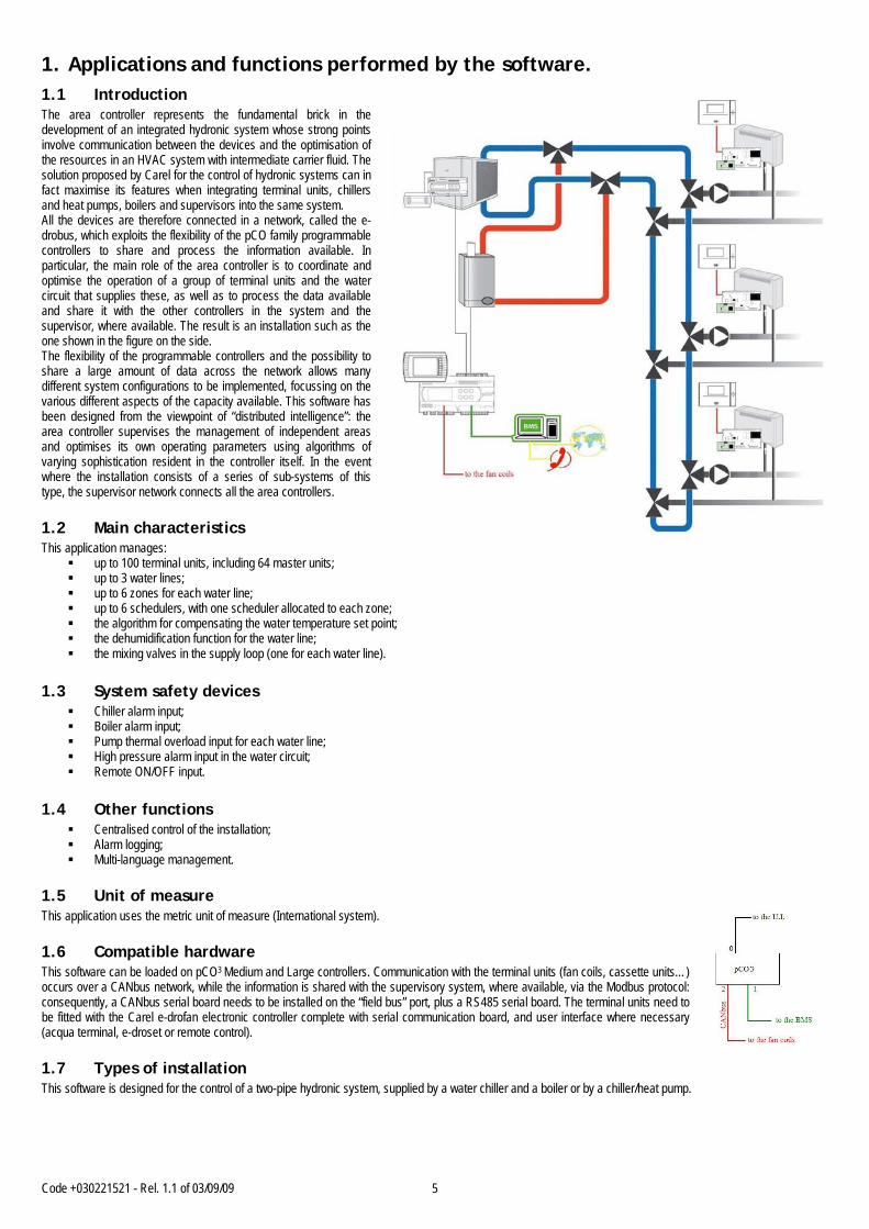
1. Applications and functions performed by the software. 1.1 Introduction The area controller represents the fundamental brick in the development of an integrated hydronic system whose strong points involve communication between the devices and the optimisation of the resources in an HVAC system with intermediate carrier fluid. The solution proposed by Carel for the control of hydronic systems can in fact maximise its features when integrating terminal units, chillers and heat pumps, boilers and supervisors into the same system. All the devices are therefore connected in a network, called the e-drobus, which exploits the flexibility of the pCO family programmable controllers to share and process the information available. In particular, the main role of the area controller is to coordinate and optimise the operation of a group of terminal units and the water circuit that supplies these, as well as to process the data available and share it with the other controllers in the system and the supervisor, where available. The result is an installation such as the one shown in the figure on the side. The flexibility of the programmable controllers and the possibility to share a large amount of data across the network allows many different system configurations to be implemented, focussing on the various different aspects of the capacity available. This software has been designed from the viewpoint of “distributed intelligence”: the area controller supervises the management of independent areas and optimises its own operating parameters using algorithms of varying sophistication resident in the controller itself. In the event where the installation consists of a series of sub-systems of this type, the supervisor network connects all the area controllers. 1.2 Main characteristics This application manages:
up to 100 terminal units, including 64 master units; up to 3 water lines; up to 6 zones for each water line; up to 6 schedulers, with one scheduler allocated to each zone; the algorithm for compensating the water temperature set point; the dehumidification function for the water line; the mixing valves in the supply loop (one for each water line).
1.3 System safety devices
Chiller alarm input; Boiler alarm input; Pump thermal overload input for each water line; High pressure alarm input in the water circuit; Remote ON/OFF input.
1.4 Other functions
Centralised control of the installation; Alarm logging; Multi-language management.
1.5 Unit of measure This application uses the metric unit of measure (International system). 1.6 Compatible hardware This software can be loaded on pCO3 Medium and Large controllers. Communication with the terminal units (fan coils, cassette units…) occurs over a CANbus network, while the information is shared with the supervisory system, where available, via the Modbus protocol: consequently, a CANbus serial board needs to be installed on the “field bus” port, plus a RS485 serial board. The terminal units need to be fitted with the Carel e-drofan electronic controller complete with serial communication board, and user interface where necessary (acqua terminal, e-droset or remote control). 1.7 Types of installation This software is designed for the control of a two-pipe hydronic system, supplied by a water chiller and a boiler or by a chiller/heat pump.
Code +030221521 - Rel. 1.1 of 03/09/09 6
2. The user terminal 2.1 Type and operation This application is designed for operation on two types of user terminal, that is:
1. PGD1 LCD user terminal; 2. PGD3 touch screen user terminal.
The user terminal can be used to perform all the operations allowed by the application program installed. It also displays the operating conditions of the unit. The user terminal can be used to set all the operating parameters of the unit in real time. The correct operation of the unit does not require the user terminal to be connected.
Important note: for the correct operation of the terminal, when loading the software onto the pCO* programmable controller, all the binary files (.iup) corresponding to the languages and the types of terminal must also be transferred; the software automatically recognises the terminal connected. If more than one terminal is connected, the software gives priority to the pGD3 terminal, however the terminal used can be set in the SERVICE PAR. menu.
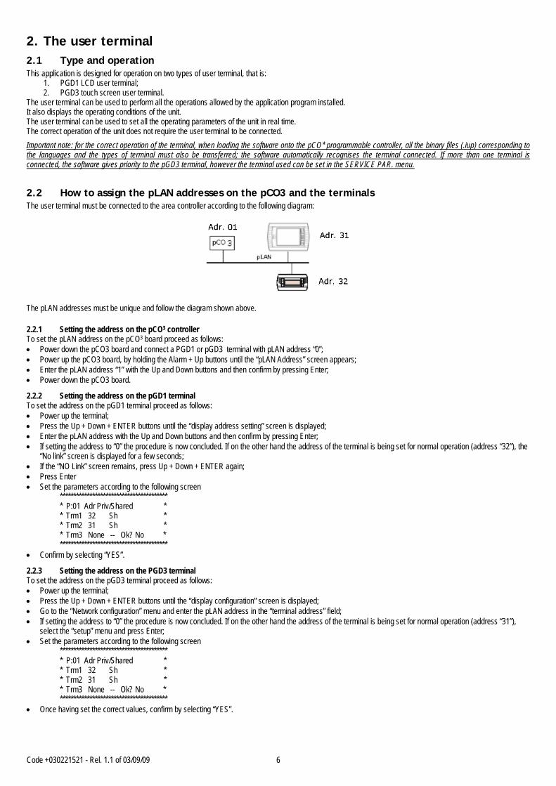
2.2 How to assign the pLAN addresses on the pCO3 and the terminals The user terminal must be connected to the area controller according to the following diagram:
The pLAN addresses must be unique and follow the diagram shown above.
2.2.1 Setting the address on the pCO3 controller To set the pLAN address on the pCO3 board proceed as follows: • Power down the pCO3 board and connect a PGD1 or pGD3 terminal with pLAN address “0”; • Power up the pCO3 board, by holding the Alarm + Up buttons until the “pLAN Address” screen appears; • Enter the pLAN address “1” with the Up and Down buttons and then confirm by pressing Enter; • Power down the pCO3 board.
2.2.2 Setting the address on the pGD1 terminal To set the address on the pGD1 terminal proceed as follows: • Power up the terminal; • Press the Up + Down + ENTER buttons until the “display address setting” screen is displayed; • Enter the pLAN address with the Up and Down buttons and then confirm by pressing Enter; • If setting the address to “0” the procedure is now concluded. If on the other hand the address of the terminal is being set for normal operation (address “32”), the
“No link” screen is displayed for a few seconds; • If the “NO Link” screen remains, press Up + Down + ENTER again; • Press Enter • Set the parameters according to the following screen
**************************************** * P:01 Adr Priv/Shared * * Trm1 32 Sh * * Trm2 31 Sh * * Trm3 None -- Ok? No * ****************************************
• Confirm by selecting “YES”.
2.2.3 Setting the address on the PGD3 terminal To set the address on the pGD3 terminal proceed as follows: • Power up the terminal; • Press the Up + Down + ENTER buttons until the “display configuration” screen is displayed; • Go to the “Network configuration” menu and enter the pLAN address in the “terminal address” field; • If setting the address to “0” the procedure is now concluded. If on the other hand the address of the terminal is being set for normal operation (address “31”),
select the “setup” menu and press Enter; • Set the parameters according to the following screen
**************************************** * P:01 Adr Priv/Shared * * Trm1 32 Sh * * Trm2 31 Sh * * Trm3 None -- Ok? No * ****************************************
• Once having set the correct values, confirm by selecting “YES”.

Code +030221521 - Rel. 1.1 of 03/09/09 7
2.3 pGD1 terminal
Button Description
ALARM displays the alarms, mutes the buzzer and deletes the active alarms UP if the cursor is in the home position (top left corner), scrolls up the screens in the same group; if the cursor is in a setting field, increases the
value DOWN if the cursor is in the home position (top left corner), scrolls down the screens in the same group; if the cursor is in a setting field, decreases
the value ENTER used to move the cursor from the home position (top left corner) to the setting fields, in the setting fields confirms the set value and moves
to the next parameter PRG accesses the menu for selecting the group of parameters to be displayed/modified, access to the parameters is confirmed by pressing the
[Enter] button ESC returns to the immediately previous menu. 2.4 pGD3 terminal
Button Description
ON/OFF pressing for at least 3s switches the area controller on/off ALARM displays the alarms, mutes the buzzer and deletes the active alarms UP if the cursor is in the home position (top left corner), scrolls up the screens in the same group; if the cursor is in a setting field, increases the
value DOWN if the cursor is in the home position (top left corner), scrolls down the screens in the same group; if the cursor is in a setting field, decreases
the value ENTER used to move the cursor from the home position (top left corner) to the setting fields, in the setting fields confirms the set value and moves
to the next parameter PRG accesses the menu for selecting the group of parameters to be displayed/modified, access to the parameters is confirmed by pressing the
[Enter] button ESC returns to the immediately previous menu. 2.5 Changing the display During the system maintenance operations, it may be necessary to modify the priority that is automatically assigned to the user terminals. To change the display from the pGD3 terminal (address 31 in the pLAN network) to a pGD1 terminal (address 32 in the pLAN network), access menu 6.a.2 (change language) and set the item in the Change display field to pGD1.
ALARM UP
PRG ENTER
ESC DOWN
UP
ENTER
DOWN
ON/OFF
ALARM PRG ESC

Code +030221521 - Rel. 1.1 of 03/09/09 8
3. Installing the default values When the controller is booted up for the first time, the software automatically the assigns default values (selected by CAREL) to all the system configuration parameters. Always check the connections between the various boards and terminals before powering up the pCO* board/boards. This section describes the procedure for restoring the default values, useful when needing to reset the system. This operation does not need to be performed when first starting the system. WARNING! this procedure irreversibly deletes any settings made by the user. Proceed as follows: • press PRG (the LED on the PRG button will come on) and select the MANUFACTURER menu; • enter the password using the UP and DOWN buttons and then press ENTER: this will access the “manufacturer” configuration branch; • select the INITIALISE menu to access to default installation screen (7.d.1); • press ENTER to select the option YES or NO; • select the option YES: the system loads the default values and prompts to wait until the operation is completed; • re-start the controller, as required by the message displayed on the terminal. 4. Selecting the language When the unit is switched on, by default a screen is displayed for selecting the language (Italian/English). This screen is displayed for 30 seconds, after which the application automatically opens the main menu. The language can be selected at any time, as follows: • Press PRG (the LED on the PRG button will come on) and select the SERVICE menu; • Select the LANGUAGE sub-menu (6.a.1); • press ENTER and select the desired language; • press ENTER to confirm. The initial language selection screen can then be disabled: • Press PRG (the LED on the PRG button will come on) and select the SERVICE menu; • Select the LANGUAGE sub-menu; • Scroll the menu to the page for enabling the initial screen (6.a.2); • press ENTER to enable or disable the screen.

Code +030221521 - Rel. 1.1 of 03/09/09 9
5. List of inputs/outputs 5.1 DIGITAL INPUTS N. pCO3 MEDIUM and LARGE ID 1 Pump 1 thermal overload ID 2 Pump 2 thermal overload ID 3 Pump 3 thermal overload ID 4 Cooling/Heating changeover ID 5 Generic chiller alarm ID 6 Generic boiler alarm ID 7 High water circuit pressure ID 8 Remote On-Off 5.2 ANALOGUE INPUTS N. pCO3 MEDIUM and LARGE B 1 Outside temperature B 2 Boiler temperature B 3 Outlet temperature, line 1 B 4 Outlet temperature, line 2 B 5 Outlet temperature, line 3 B 6 Humidity, line 1 B 7 Humidity, line 2 B 8 Humidity, line 3 B 9 B10 5.3 DIGITAL OUTPUTS N. pCO3 MEDIUM and LARGE No 1 Pump line 1 No 2 Pump line 2 No 3 Pump line 3 No 4 Chiller On/Off No 5 Boiler On/Off No 6 Cooling / Heating No 7 No 8 Alarm No 9 Dehumidification, line 1 No 10 Dehumidification, line 2 No 11 Dehumidification, line 3 5.4 ANALOGUE OUTPUTS N. pCO3 MEDIUM and LARGE Y 1 Valve, line 1 Y 2 Valve, line 2 Y 3 Valve, line 3 Y 4 Chiller set point offset
Code +030221521 - Rel. 1.1 of 03/09/09 10
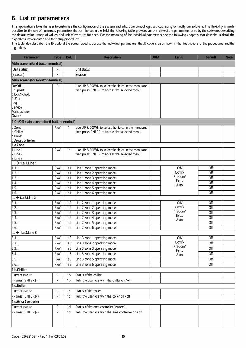
6. List of parameters This application allows the user to customise the configuration of the system and adjust the control logic without having to modify the software. This flexibility is made possible by the use of numerous parameters that can be set in the field: the following table provides an overview of the parameters used by the software, describing the default value, range of values and unit of measure for each. For the meaning of the individual parameters see the following chapters that describe in detail the algorithms implemented and the setup procedures. The table also describes the ID code of the screen used to access the individual parameters: the ID code is also shown in the descriptions of the procedures and the algorithms.
Parameters Type Ref. Description UOM Limits Default Note Main screen (for 6-button terminal) (Unit status) R
Unit status
(Season) R Season
Main screen (for 6-button terminal) On/Off Set point Clock/Sched. In/Out Log Service Manufacturer Graphs
R Use UP & DOWN to select the fields in the menu and then press ENTER to access the selected menu
1 On/Off main screen (for 6-button terminal) a.Zone b.Chiller c.Boiler d.Area Controller
R/W 1 Use UP & DOWN to select the fields in the menu and then press ENTER to access the selected menu
1.a.Zone 1.Line 1 2.Line 2 3.Line 3
R/W 1a Use UP & DOWN to select the fields in the menu and then press ENTER to access the selected menu
… 1.a.1.Line 1 1.1… R/W 1a1 Line 1 zone 1 operating mode Off 1.2… R/W 1a1 Line 1 zone 2 operating mode Off 1.3… R/W 1a1 Line 1 zone 3 operating mode Off 1.4… R/W 1a1 Line 1 zone 4 operating mode Off 1.5… R/W 1a1 Line 1 zone 5 operating mode Off 1.6… R/W 1a1 Line 1 zone 6 operating mode
Off/ Comf./
PreCom/ Eco./ Auto
Off … 1.a.2.Line 2 2.1… R/W 1a2 Line 2 zone 1 operating mode Off 2.2… R/W 1a2 Line 2 zone 2 operating mode Off 2.3… R/W 1a2 Line 2 zone 3 operating mode Off 2.4… R/W 1a2 Line 2 zone 4 operating mode Off 2.5… R/W 1a2 Line 2 zone 5 operating mode Off 2.6… R/W 1a2 Line 2 zone 6 operating mode
Off/ Comf./
PreCom/ Eco./ Auto
Off … 1.a.3.Line 3 3.1… R/W 1a3 Line 3 zone 1 operating mode Off 3.2… R/W 1a3 Line 3 zone 2 operating mode Off 3.3… R/W 1a3 Line 3 zone 3 operating mode Off 3.4… R/W 1a3 Line 3 zone 4 operating mode Off 3.5… R/W 1a3 Line 3 zone 5 operating mode Off 3.6… R/W 1a3 Line 3 zone 6 operating mode
Off/ Comf./
PreCom/ Eco./ Auto
Off 1.b.Chiller Current status: R 1b Status of the chiller >>press [ENTER]<< R 1b Tells the user to switch the chiller on / off 1.c.Boiler Current status: R 1c Status of the boiler >>press [ENTER]<< R 1c Tells the user to switch the boiler on / off 1.d.Area Controller Current status: R 1d Status of the area controller (system) >>press [ENTER]<< R 1d Tells the user to switch the area controller on / off
Code +030221521 - Rel. 1.1 of 03/09/09 11
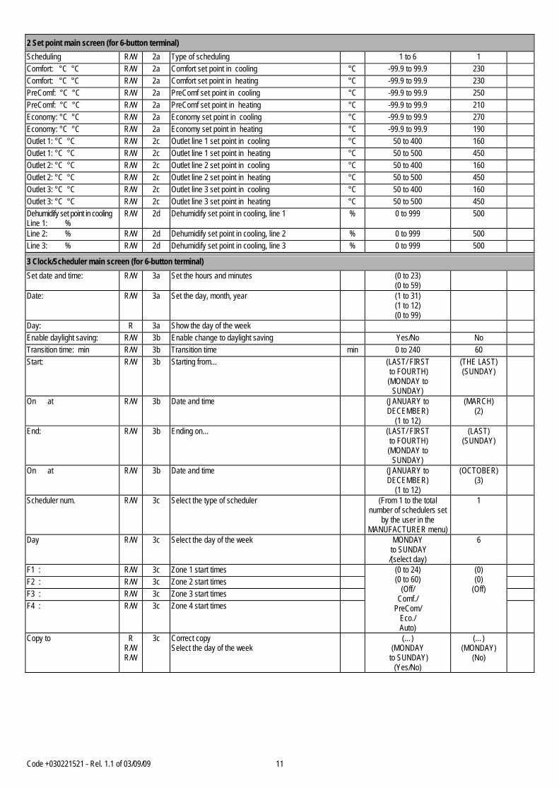
2 Set point main screen (for 6-button terminal) Scheduling R/W 2a Type of scheduling 1 to 6 1 Comfort: °C °C R/W 2a Comfort set point in cooling °C -99.9 to 99.9 230 Comfort: °C °C R/W 2a Comfort set point in heating °C -99.9 to 99.9 230 PreComf: °C °C R/W 2a PreComf set point in cooling °C -99.9 to 99.9 250 PreComf: °C °C R/W 2a PreComf set point in heating °C -99.9 to 99.9 210 Economy: °C °C R/W 2a Economy set point in cooling °C -99.9 to 99.9 270 Economy: °C °C R/W 2a Economy set point in heating °C -99.9 to 99.9 190 Outlet 1: °C °C R/W 2c Outlet line 1 set point in cooling °C 50 to 400 160 Outlet 1: °C °C R/W 2c Outlet line 1 set point in heating °C 50 to 500 450 Outlet 2: °C °C R/W 2c Outlet line 2 set point in cooling °C 50 to 400 160 Outlet 2: °C °C R/W 2c Outlet line 2 set point in heating °C 50 to 500 450 Outlet 3: °C °C R/W 2c Outlet line 3 set point in cooling °C 50 to 400 160 Outlet 3: °C °C R/W 2c Outlet line 3 set point in heating °C 50 to 500 450 Dehumidify set point in cooling Line 1: %
R/W 2d Dehumidify set point in cooling, line 1 % 0 to 999 500
Line 2: % R/W 2d Dehumidify set point in cooling, line 2 % 0 to 999 500 Line 3: % R/W 2d Dehumidify set point in cooling, line 3 % 0 to 999 500
3 Clock/Scheduler main screen (for 6-button terminal) Set date and time: R/W 3a Set the hours and minutes (0 to 23)
(0 to 59)
Date: R/W 3a Set the day, month, year (1 to 31) (1 to 12) (0 to 99)
Day: R 3a Show the day of the week Enable daylight saving: R/W 3b Enable change to daylight saving Yes/No No Transition time: min R/W 3b Transition time min 0 to 240 60 Start: R/W 3b Starting from… (LAST/ FIRST
to FOURTH) (MONDAY to
SUNDAY)
(THE LAST) (SUNDAY)
On at R/W 3b Date and time (JANUARY to DECEMBER)
(1 to 12)
(MARCH) (2)
End: R/W 3b Ending on… (LAST/ FIRST to FOURTH) (MONDAY to
SUNDAY)
(LAST) (SUNDAY)
On at R/W 3b Date and time (JANUARY to DECEMBER)
(1 to 12)
(OCTOBER) (3)
Scheduler num. R/W 3c Select the type of scheduler (From 1 to the total number of schedulers set
by the user in the MANUFACTURER menu)
1
Day R/W 3c Select the day of the week MONDAY to SUNDAY /(select day)
6
F1 : R/W 3c Zone 1 start times F2 : R/W 3c Zone 2 start times F3 : R/W 3c Zone 3 start times F4 : R/W 3c Zone 4 start times
(0 to 24) (0 to 60)
(Off/ Comf./
PreCom/ Eco./ Auto)
(0) (0)
(Off)
Copy to R R/W R/W
3c Correct copy Select the day of the week
(…) (MONDAY
to SUNDAY) (Yes/No)
(…) (MONDAY)
(No)
Code +030221521 - Rel. 1.1 of 03/09/09 12
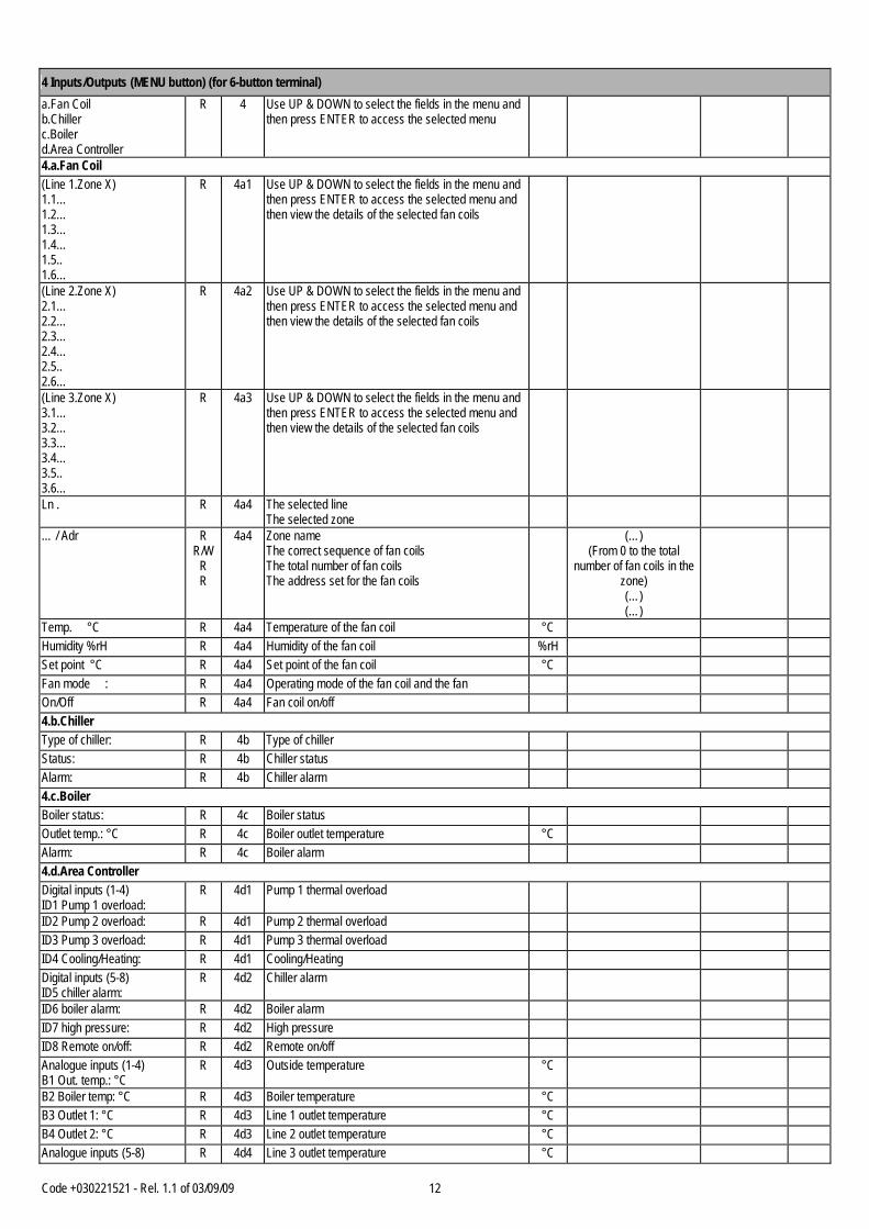
4 Inputs/Outputs (MENU button) (for 6-button terminal) a.Fan Coil b.Chiller c.Boiler d.Area Controller
R 4 Use UP & DOWN to select the fields in the menu and then press ENTER to access the selected menu
4.a.Fan Coil (Line 1.Zone X) 1.1… 1.2… 1.3… 1.4… 1.5.. 1.6…
R 4a1 Use UP & DOWN to select the fields in the menu and then press ENTER to access the selected menu and then view the details of the selected fan coils
(Line 2.Zone X) 2.1… 2.2… 2.3… 2.4… 2.5.. 2.6…
R 4a2 Use UP & DOWN to select the fields in the menu and then press ENTER to access the selected menu and then view the details of the selected fan coils
(Line 3.Zone X) 3.1… 3.2… 3.3… 3.4… 3.5.. 3.6…
R 4a3 Use UP & DOWN to select the fields in the menu and then press ENTER to access the selected menu and then view the details of the selected fan coils
Ln . R 4a4 The selected line The selected zone
… / Adr R R/W
R R
4a4 Zone name The correct sequence of fan coils The total number of fan coils The address set for the fan coils
(…) (From 0 to the total
number of fan coils in the zone) (…) (…)
Temp. °C R 4a4 Temperature of the fan coil °C Humidity %rH R 4a4 Humidity of the fan coil %rH Set point °C R 4a4 Set point of the fan coil °C Fan mode : R 4a4 Operating mode of the fan coil and the fan On/Off R 4a4 Fan coil on/off 4.b.Chiller Type of chiller: R 4b Type of chiller Status: R 4b Chiller status Alarm: R 4b Chiller alarm 4.c.Boiler Boiler status: R 4c Boiler status Outlet temp.: °C R 4c Boiler outlet temperature °C Alarm: R 4c Boiler alarm 4.d.Area Controller Digital inputs (1-4) ID1 Pump 1 overload:
R 4d1 Pump 1 thermal overload
ID2 Pump 2 overload: R 4d1 Pump 2 thermal overload ID3 Pump 3 overload: R 4d1 Pump 3 thermal overload ID4 Cooling/Heating: R 4d1 Cooling/Heating Digital inputs (5-8) ID5 chiller alarm:
R 4d2 Chiller alarm
ID6 boiler alarm: R 4d2 Boiler alarm ID7 high pressure: R 4d2 High pressure ID8 Remote on/off: R 4d2 Remote on/off Analogue inputs (1-4) B1 Out. temp.: °C
R 4d3 Outside temperature °C
B2 Boiler temp: °C R 4d3 Boiler temperature °C B3 Outlet 1: °C R 4d3 Line 1 outlet temperature °C B4 Outlet 2: °C R 4d3 Line 2 outlet temperature °C Analogue inputs (5-8) R 4d4 Line 3 outlet temperature °C
Code +030221521 - Rel. 1.1 of 03/09/09 13
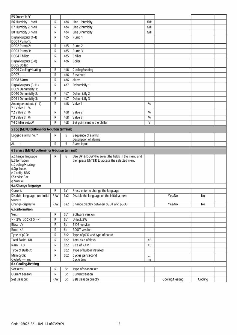
B5 Outlet 3: °C B6 Humidity 1: %rH R 4d4 Line 1 humidity %rH B7 Humidity 2: %rH R 4d4 Line 2 humidity %rH B8 Humidity 3: %rH R 4d4 Line 3 humidity %rH Digital outputs (1-4) DO01 Pump 1:
R 4d5 Pump 1
DO02 Pump 2: R 4d5 Pump 2 DO03 Pump 3: R 4d5 Pump 3 DO04 Chiller: R 4d5 Chiller Digital outputs (5-8) DO05 Boiler:
R 4d6 Boiler
DO06 Cooling/Heating: R 4d6 Cooling/heating DO07 -- -- R 4d6 Reserved DO08 Alarm: R 4d6 alarm Digital outputs (9-11) DO09 Dehumidify 1:
R 4d7 Dehumidify 1
DO10 Dehumidify 2: R 4d7 Dehumidify 2 DO11 Dehumidify 3: R 4d7 Dehumidify 3 Analogue outputs (1-4) Y1 Valve 1: %
R 4d8 Valve 1 %
Y2 Valve 2: % R 4d8 Valve 2 % Y3 Valve 3: % R 4d8 Valve 3 % Y4 Chiller setp.:V R 4d8 Set point sent to the chiller V
5 Log (MENU button) (for 6-button terminal) Logged alarms no. ° R 5 Sequence of alarms
Description of alarms
AL : R 5 Alarm input
6 Service (MENU button) (for 6-button terminal) a.Change language b.Information c.Cooling/Heating d.Op. hours e.Config. BMS f.Service.Par g.Manual
R 6 Use UP & DOWN to select the fields in the menu and then press ENTER to access the selected menu
6.a.Change language Current: R 6a1 Press enter to change the language Disable language on initial screen:
R/W 6a2 Disable the language on the initial screen Yes/No No
Change display to R/W 6a2 Change display between pGD1 and pGD3 Yes/No No 6.b.Information Ver.: R 6b1 Software version >> SW LOCKED << R 6b1 Unlock SW Bios: / / R 6b1 BIOS version Boot: / / R 6b1 BOOT version Type of pCO: R 6b2 Type of pCO and type of board Total flash: KB R 6b2 Total size of flash KB Ram: KB R 6b2 Size of RAM KB Type of Built-In: R 6b2 Type of built-in installed Main cycle: Cycle/s --> ms
R 6b2 Cycles per second Cycle time
… ms
6.c.Cooling/Heating Set seas: R 6c Type of season set Current season: R 6c Current season Set season: R/W 6c Sets season directly Cooling/Heating Cooling
Code +030221521 - Rel. 1.1 of 03/09/09 14
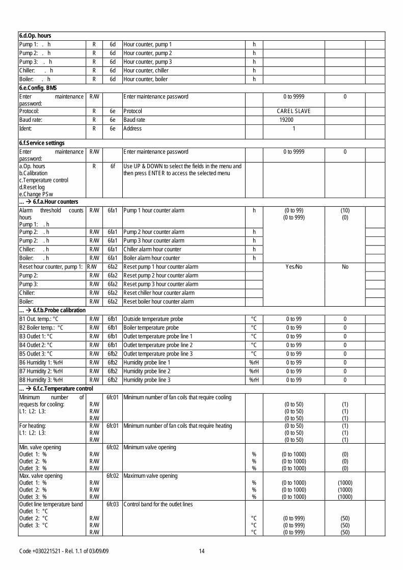
6.d.Op. hours Pump 1: . h R 6d Hour counter, pump 1 h Pump 2: . h R 6d Hour counter, pump 2 h Pump 3: . h R 6d Hour counter, pump 3 h Chiller: . h R 6d Hour counter, chiller h Boiler: . h R 6d Hour counter, boiler h 6.e.Config. BMS Enter maintenance password:
R/W Enter maintenance password 0 to 9999 0
Protocol: R 6e Protocol CAREL SLAVE Baud rate: R 6e Baud rate 19200 Ident:
R 6e Address 1
6.f.Service settings Enter maintenance password:
R/W Enter maintenance password 0 to 9999 0
a.Op. hours b.Calibration c.Temperature control d.Reset log e.Change PSw
R 6f Use UP & DOWN to select the fields in the menu and then press ENTER to access the selected menu
… 6.f.a.Hour counters Alarm threshold counts hours Pump 1: . h
R/W 6fa1 Pump 1 hour counter alarm h
Pump 2: . h R/W 6fa1 Pump 2 hour counter alarm h Pump 2: . h R/W 6fa1 Pump 3 hour counter alarm h Chiller: . h R/W 6fa1 Chiller alarm hour counter h Boiler: . h R/W 6fa1 Boiler alarm hour counter h
(0 to 99) (0 to 999)
(10) (0)
Reset hour counter, pump 1: R/W 6fa2 Reset pump 1 hour counter alarm Pump 2: R/W 6fa2 Reset pump 2 hour counter alarm Pump 3: R/W 6fa2 Reset pump 3 hour counter alarm Chiller: R/W 6fa2 Reset chiller hour counter alarm Boiler: R/W 6fa2 Reset boiler hour counter alarm
Yes/No No
… 6.f.b.Probe calibration B1 Out. temp.: °C R/W 6fb1 Outside temperature probe °C 0 to 99 0 B2 Boiler temp.: °C R/W 6fb1 Boiler temperature probe °C 0 to 99 0 B3 Outlet 1: °C R/W 6fb1 Outlet temperature probe line 1 °C 0 to 99 0 B4 Outlet 2: °C R/W 6fb1 Outlet temperature probe line 2 °C 0 to 99 0 B5 Outlet 3: °C R/W 6fb2 Outlet temperature probe line 3 °C 0 to 99 0 B6 Humidity 1: %rH R/W 6fb2 Humidity probe line 1 %rH 0 to 99 0 B7 Humidity 2: %rH R/W 6fb2 Humidity probe line 2 %rH 0 to 99 0 B8 Humidity 3: %rH R/W 6fb2 Humidity probe line 3 %rH 0 to 99 0 … 6.f.c.Temperature control Minimum number of requests for cooling: L1: L2: L3:
R/W R/W R/W
6fc01 Minimum number of fan coils that require cooling (0 to 50) (0 to 50) (0 to 50)
(1) (1) (1)
For heating: L1: L2: L3:
R/W R/W R/W
6fc01 Minimum number of fan coils that require heating (0 to 50) (0 to 50) (0 to 50)
(1) (1) (1)
Min. valve opening Outlet 1: % Outlet 2: % Outlet 3: %
R/W R/W R/W
6fc02 Minimum valve opening % % %
(0 to 1000) (0 to 1000) (0 to 1000)
(0) (0) (0)
Max. valve opening Outlet 1: % Outlet 2: % Outlet 3: %
R/W R/W R/W
6fc02 Maximum valve opening % % %
(0 to 1000) (0 to 1000) (0 to 1000)
(1000) (1000) (1000)
Outlet line temperature band Outlet 1: °C Outlet 2: °C Outlet 3: °C
R/W R/W R/W
6fc03 Control band for the outlet lines
°C °C °C
(0 to 999) (0 to 999) (0 to 999)
(50) (50) (50)
Code +030221521 - Rel. 1.1 of 03/09/09 15
Type of control Outlet 1: R/W 6fc04 Outlet line 1 control type and delay s Outlet 2: R/W 6fc04 Outlet line 2 control type and delay s Outlet 3: R/W 6fc04 Outlet line 3 control type and delay s
(PROP/ PROP.+INT.)
(0 to 999)
(PROP) (0)
Set point offset sent to the chiller: °C
R 6fc05 Set point sent to the chiller °C
Compensation Type selected:
R/W 6fc06 Type of compensation FROM CHILLER /FROM A.C. OUT.TEMP.
/FROM A.C. F.C. SLIDING
FROM CHILLER
Max compens. /offset: °C
R/W 6fc06 Maximum compensation/offset °C (-999 to 999) 50
Compensation from A.C. Outside temperature Setp. °C °C
R/W 6fc06 Compensation from A.C. on Outside temperature Set point for cooling / heating
°C °C
(-999 to 999) (-999 to 999)
(25) (0)
Differential °C °C R/W 6fc07 Compensation from A.C. on Outside temperature differential for cooling/heating
°C °C
(0 to 999) (0 to 999)
(10) (10)
Compensation from A.C. F.C. sliding threshold: °C
R/W 6fc08 Compensation from C.A. threshold sliding °C (-999 to 999) (20)
Average calculation:min R/W 6fc08 Compensation from A.C. F.C. calculation of sliding average
min (0 to 999) (60)
Select season from: R/W 6fc09 Type of season selection DIGITAL IN. /KEYPAD /B.M.S.
/KEYPAD/BMS /AUTO MODE
KEYPAD
Current season: R 6fc10 Current season Set season: R/W 6fc10 Select season Auto/Fix day Auto Start cooling: / R/W
R/W 6fc10 Starting day and month in cooling (1 to 31)
(1 to 12) (15) (5)
Start heating: / R/W R/W
6fc10 Starting day and month in heating (1 to 31) (1 to 12)
(30) (9)
Cooling threshold: °C R/W 6fc10 Cooling changeover threshold °C (-999 to 999) (250) Heating threshold: °C R/W 6fc10 Heating changeover threshold °C (-999 to 999) (100) Change delay R/W 6fc10 Changeover delay time h (0 to 999) (1) Dehumidify dead zone and differential in cooling: % %
R/W 6fc11 Dehumidify dead zone and differential in cooling
% %
(0 to 999) (0 to 999)
(100) (100)
Line 2: % % R/W 6fc11 Dehumidify dead zone and differential in cooling for line 2
% %
(0 to 999) (0 to 999)
(100) (100)
Line 3: % % R/W 6fc11 Dehumidify dead zone and differential in cooling for line 3
% %
(0 to 999) (0 to 999)
(100) (100)
… 6.f.d.Data logger reset Delete log: R/W 6fd Deletes alarm log Yes/No No wait... R 6fd Wait to delete alarms … 6.f.e.Change password Enter new maintenance password:
R/W 6fe Enter new maintenance password 0 to 9999 0
6.g.Manual control Enter new maintenance password personnel:
R/W Enter new password 0 to 9999 0
Force outputs Pump 1: -
R/W 6g Force pump 1
Pump 2: - R/W 6g Force pump 2 Pump 3: - R/W 6g Force pump 3 Alarm: R/W 6g Force alarm Chiller: R/W 6g Force chiller Boiler: R/W 6g Force boiler Dehumidify 1: R/W 6g Force dehumidify line 1 Dehumidify 2: R/W 6g Force dehumidify line 2 Dehumidify 3: R/W 6g Force dehumidify line 3 V.1: R/W 6g Force valve line 1 V.1: R/W 6g Force valve line 2 V.1: R/W 6g Force valve line 3

Code +030221521 - Rel. 1.1 of 03/09/09 16
7 MANUFACTURER (MENU button) (for 6-button terminal) Enter maintenance password:
R/W Enter maintenance password 0 to 9999 0
a.Configuration b.In/out. c.Manufacturer par. d.Initialise e.Test In/Out
R 7 Use UP & DOWN to select the fields in the menu and then press ENTER to access the selected menu
7.a.Configuration No.Water lines: R/W 7a1 Total number of lines 1 to 3 3 No.zones line 1: R/W 7a1 Number of zone line 1 0 to 6 0 No.zones line 2: R/W 7a1 Number of zone line 2 0 to 6 0 No.zones line 3: R/W 7a1 Number of zone line 3 0 to 6 0 No.schedulers: R/W 7a1 Number of schedulers 1 to 6 1 Line zone R/W 7a2 Select the line and the zone (1 to 3)
(1 to 6) (1) (1)
Zone name… R/W 7a2 Set the name of the zone Space/a to z/0 to 9 space 01: … 15: R/W 7a2 Set the address for the fan coil in the zone 20 to 121 20 (DISAB.) Type of scheduler R/W 7a2 Set the scheduler for the zone 1 to 6 1 Protocol settings R/W 7a3 Carel Master protocol baud rate baud 1200/2400/
4800/ 9600/19200 19200
Device timeout: ms R/W 7a3 Device timeout ms 100 to 1000 500 Recall time: s R/W 7a3 Recall time s 0 to 300 60 Num attempts: R/W 7a3 Number of attempts 0 to 9 3 7.b.IN/OUT Probe configuration Humidity line 1 min value: %rH max value: %rH
R/W R/W
7b1 Humidity line 1 probe configuration
%rH %rH
(0 to 1000) (0 to 1000)
(0) (100)
Humidity line 2 min value: %rH max value: %rH
R/W R/W
7b1 Humidity line 2 probe configuration
%rH %rH
(0 to 1000) (0 to 1000)
(0) (100)
Humidity line 3 min value: %rH max value: %rH
R/W R/W
7b2 Humidity line 3 probe configuration
%rH %rH
(0 to 1000) (0 to 1000)
(0) (100)
Enable type of probes B1 Out. temp:
R/W 7b3 Enable probe B1 for outside temperature NTC ENAB./DISAB. NTC ENAB.
B2 Boiler: R/W 7b3 Enable probe B2 for boiler temperature probe NTC ENAB./DISAB. NTC ENAB. B3 Outlet 1: R/W 7b3 Enable probe B3 for outlet probe line 1 NTC ENAB./DISAB. NTC ENAB. B4 Outlet 2: R/W 7b3 Enable probe B4 for outlet probe line 2 NTC ENAB./DISAB. NTC ENAB. B5 Outlet 3: R/W 7b4 Enable probe B5 for outlet probe line 3 NTC ENAB./DISAB. NTC ENAB. B6 Humid.1: R/W 7b4 Enable probe B6 for humidity probe line 1 B7 Humid.2: R/W 7b4 Enable probe B7 for humidity probe line 2 B8 Humid.3: R/W 7b4 Enable probe B8 for humidity probe line 3
(NTC ENAB./DISAB.) (NTC/PT1000
/0-1V/0-10V/4-20mA /On-Off/0-5V)
(AB) (0-1V)
Probe alarm delay B1 Out. temp: s
R/W 7b5 Probe alarm delay s 0 to 999 60
B2 Boiler: s R/W 7b5 Boiler probe B2 alarm delay s 0 to 999 60 B3 Outlet 1: s R/W 7b5 Outlet line 1 probe B3 alarm delay s 0 to 999 60 B4 Outlet 2: s R/W 7b5 Outlet line 2 probe B4 alarm delay s 0 to 999 60 Probe alarm delay B4 Outlet 3: s
R/W 7b6 Outlet line 3 probe B5 alarm delay s 0 to 999 60
B6 Humid.1: s R/W 7b6 Humidity probe 1 alarm delay s 0 to 999 60 B7 Humid.2: s R/W 7b6 Humidity probe 2 alarm delay s 0 to 999 60 B8 Humid.3: s R/W 7b6 Humidity probe 3 alarm delay s 0 to 999 60

Code +030221521 - Rel. 1.1 of 03/09/09 17
7.c.Carel settings Type of chiller: R/W 7c1 Type of chiller CHILLER
CHILLER/HEAT PUMP CHILLER
Boiler temp. threshold: °C R/W 7c2 High boiler temperature threshold °C 0 to 999 850 Differential: °C R/W 7c2 High boiler temperature differential °C 0 to 300 50 Boiler alarm delay from Digital input: s
R/W 7c2 Boiler alarm from digital input s 0 to 999 0
Valve present or not Line 1:
R/W 7c3 Line 1 valve present or not
Line 2: R/W 7c3 Line 2 valve present Line 3: R/W 7c3 Line 3 valve present
NOT PRESENT /PRESENT
PRESENT
Valve opening delay from Area controller on Valve 1: s
R/W 7c4 Valve 1 opening delay from area controller s
Valve 2: s R/W 7c4 Valve 2 opening delay from area controller s Valve 3: s R/W 7c4 Valve 1 opening delay from area controller s
0 to 999 180
Area Controller cooling set point low : °C
R/W 7c5 Area Controller minimum cooling set point °C -999 to 999 40
High: °C R/W 7c5 Area Controller maximum cooling set point °C -999 to 999 500 Area controller Temperature heating set point low: °C
R/W 7c6 Area Controller minimum heating set point °C -999 to 999 40
High: °C
R/W 7c6 Area Controller maximum heating set point
°C -999 to 999 500
Scheduler cooling temperature limit low : °C
R/W 7c7 Cooling temperature with scheduler Minimum value
°C -999 to 999 150
Cooling high: °C R/W 7c7 Cooling temperature with scheduler Maximum value
°C -999 to 999 350
Heating low: °C R/W 7c7 Heating temperature with scheduler minimum set point value
°C -999 to 999 150
Heating high: °C R/W 7c7 Heating temperature with scheduler maximum set point value
°C -999 to 999 350
7.d.Initialisation Default values: R/W 7d1 Load the default values Yes/No No WAIT... R 7d1 Wait for default values Initialise scheduler: R/W 7d2 Initialise scheduler Yes/No No Please wait R 7d2 Wait for initial scheduling values Enter new manufacturer password:
R/W 7d3 Enter new manufacturer password 0 to 9999 0
7.e.Test IN/OUT

Code +030221521 - Rel. 1.1 of 03/09/09 18
7. List of screens The area controller user interface is used to access all the functional information on the installation; this information is organised according to the structure shown below: Main Menu
1. On/Off
2. Set point
3. Date/time
4. Devices
5. Log
6. Service a. Language b. Information c. Cool/Heat d. Op. hours e. Conf. BMS -> PW1 f. Service Param. -> PW1 a. Op. hours b. Calibration c. Temperature control d. Reset log e. Change PSW g. Manual
7. Manufacturer -> PW2 a. Configuration b. In/Out c. Manufacturer param. d. Initialise
8. Graphs
The general structure of the screens is independent of the user interface connected. Some screens may have a different appearance depending on the terminal used, while the path to access the parameters remains the same. 7.1 Password Access to some of the menus is protected by a four-number password: specifically, the list shown in the previous paragraph describes the screens with protected access; in addition, two different passwords, PW1 and PW2, can be defined to limit access to groups of different screens (respectively, PW1 for some of the screens in group 6, PW2 for the screens in group 7). The default password, identical for PW1 and PW2, is 1234 and can be changed by the user at any time. To change the password to access some screens in the SERVICE menu (PW1), proceed as follows: • press PRG (the LED on the PRG button will come on) and select the SERVICE menu; • select the SERVICE PAR. menu and enter the password using the UP and DOWN buttons and press ENTER; • select the CHANGE PSW menu (6.f.e); • press ENTER to select the desired field; • use the UP and DOWN buttons to select the desired value; • press ENTER to confirm. To change the password to access the MANUFACTURER menu (PW2), proceed as follows: • press PRG (the LED on the PRG button will come on) and select the MANUFACTURER menu; • enter the password using the UP and DOWN buttons and then press ENTER: this will access the “manufacturer” configuration branch; • select the INITIALISE menu to access the change password screen (7.d.1); • press ENTER to select the desired field; • use the UP and DOWN buttons to select the desired value; • press ENTER to confirm. If the password is lost or forgotten, the access code set by Carel, non-modifiable by the user, is always valid. For this application the code is 1315.

Code +030221521 - Rel. 1.1 of 03/09/09 19
8. System configuration 8.1 Devices controlled This application is designed for a two-pipe system fitted with a chiller and a boiler that produce cold and hot water respectively. The chiller must be fitted with its own controller, and the terminal units (fan coils) must be fitted with special electronic controllers and serial interfaces connected to a CANbus network. The mixing valves in the water lines that supply the fan coils are controlled by an electrical actuator. A supervisory system is also envisaged for serial communication. An example of the system is shown in the figure on the side. The area controller, which is connected to the user interface via pLAN, communicates with
the various components in the system in three distinct modes: wired logic (hardware inputs and outputs), serial CANbus and Modbus serial communication (or alternatively Carel). In particular, wired logic is used to control the actuators in the water circuit (mixing valves, pumps) and the units for the production of cold and hot water (chiller and boiler); serial communication via the CANbus network is used to control the terminal units (fan coils). Finally, the Modbus or Carel protocol is used to share the information available with an optional supervisory system: the latter point is described separately in this manual (Chap. 16).
8.1.1 Water circuit The area controller can control the circulating pump and the mixing valve in three water lines, and monitor the temperature downstream of the mixing valve. Typically, the pumps are controlled with ON/OFF logic and the valves with a 0-10 V signal. The possibility to manage up to three water lines makes the area controller extremely flexible and open to any expansions of the installation. The system only shows the user the information relating to the water lines that are enabled. 8.1.2 Chiller The area controller can directly control the activation and deactivation of a chiller via a dedicated relay. In addition, it provides a 0-10 V signal proportional to the offset applied to the chiller temperature set point, calculated by the area controller based on the compensation algorithm. A digital input is reserved for any chiller alarms. 8.1.3 Boiler The area controller can control directly the activation and deactivation of a boiler via a dedicated. In addition, it provides a 0-10 V signal proportional to the offset applied to the temperature set point, calculated by the area controller based on the compensation algorithm. A digital input is reserved for any boiler alarms. 8.1.4 Terminal units The area controller manages the terminal units via a CANbus serial connection. The terminal units must be fitted with the e-drofan electronic controller connected to a CANbus network using the special serial board. Each terminal unit can be fitted with accessories such as: user interface, ambient temperature probe and humidity probe. See the technical documents on the devices listed for further information. When setting up the network, an address must be assigned to each terminal unit connected: this operation can be performed manually from the acqua user terminal or alternatively using the dipswitches on the CANbus board; in the first case, the dipswitches on the serial board must be set a zero. The addresses must be between 21-120, inclusive. Once the configuration has been completed, it can be checked from a computer connected to the network via the special converter, running the CANspy software. For further information on these procedures, see the corresponding technical documents. Each terminal unit belongs to a zone, which in turn is physically supplied by a water line: this consideration is the basis for the logic used to assign the terminal units in this application, and that therefore identifies each fan coil based on the line/zone/unit. An example of this logic is shown in the following diagram:
The area controller can manage up to 3 water lines; 6 zones can be defined for each water line, and each zone can coordinate a maximum of 15 terminal units. In total, the area controller can manage up to a maximum of 100 terminal units, 64 of the which can be set as master units. N.B. Some basic concepts of master/slave control logic between terminal units need to be recalled. In general, considering a uniform group of terminal units (for example: all the fan coils in a room), it is often useful to assign one of the units to a higher hierarchical level (master). This allows the user to control, via a special interface, just one device, which in turn shares the appropriate information with the connected devices; these devices (slaves) operate in a coordinated manner to support the master in the thermodynamic action set on the latter. The quantity, type and direction of the data that sent and received depend on the physical network support, the communication protocol and the setting of specific parameters: for further information see to the corresponding technical documents.

Code +030221521 - Rel. 1.1 of 03/09/09 20
8.2 Configuring the system The program only shows the user the data corresponding to the devices that are enabled. Consequently, the number of water lines, the number of zones in each line and the number of schedulers need to be set. The procedure described below is used to enable the water lines, the number of zones associated with each water line and the number of schedulers that can be defined: • press PRG (the LED on the PRG button will come on) and select the MANUFACTURER menu; • enter the password using the UP and DOWN buttons and then press ENTER: this will access the “manufacturer” configuration branch; • select the CONFIGURATION menu to access the screen for configuring the system (7.a.1); • press ENTER to select the desired row (number of water lines, number of zones for water line no. 1, zones for water line no. 2, zones for water line no. 3,
number of schedulers); • use the UP and DOWN buttons to select the desired value; • press ENTER to confirm. In the same menu, once the water lines, the zones and the schedulers have been enabled, a name can be assigned (up to 11 characters available) for each zone, and then the terminal units can be allocated to the zones based on their serial addresses (variable from 21 to 120): • press PRG (the LED on the PRG button will come on) and select the MANUFACTURER menu; • enter the password using the UP and DOWN buttons and then press ENTER: this will access the “manufacturer” configuration branch; • select the CONFIGURATION menu to access the screen for configuring the system (7.a.2); • press the UP and DOWN buttons to display the page corresponding to the zone configuration; • press ENTER to select the required fields; • use the UP and DOWN buttons to select the desired value; • press ENTER to confirm. Important note: a network address must be assigned to each terminal unit before connecting the network, according to the specific procedure for each individual unit; the serial addresses of the terminal units cannot be set from the area controller. The procedure described above simply associates a certain number of terminal units, identified by the corresponding addresses, with a certain zone. 8.3 Configuring the probes The area controller directly manages the information read by eight probes (these may be different types), as follows:
- Outside temperature probe; - Boiler outlet temperature probe; - Outlet temperature probe in each water line (downstream of the mixing valve); - Centralised humidity probe connected to each water line;
All the probes can be enabled or disabled, while for the humidity probes the type of probe and the measurement limits can be defined. To do this: • press PRG (the LED on the PRG button will come on) and select the MANUFACTURER menu; • enter the password using the UP and DOWN buttons and then press ENTER: this will access the “manufacturer” configuration branch; • select the In/Out menu to access the screen for configuring the probes (7.b.1); • use the UP and DOWN buttons to scroll the pages to access the various probes; • press ENTER to select the desired row; • use the UP and DOWN buttons to select the desired value; • press ENTER to confirm. A corrective factor can be set for all the probes, defined as the deviation to be added to or subtracted from the value read: • press PRG (the LED on the PRG button will come on) and select the SERVICE menu; • select the SERVICE PAR. menu and enter the password using the UP and DOWN buttons and press ENTER; • select the CALIBRATION menu to access the screen for setting the probe offset (6.f.b.1); • use the UP and DOWN buttons to scroll the pages to access the various probes; • press ENTER to select the desired field; • use the UP and DOWN buttons to select the desired value; • press ENTER to confirm.
Code +030221521 - Rel. 1.1 of 03/09/09 21
9. System management One of the most significant features of the area controller is the possibility to manage all the devices in the system connected to the same controller from one single interface. The following paragraphs provide an overview of the main functions available. 9.1 Water circuit The area controller can manage the actuators in three water lines via three digital ON/OFF signals and three 0-10 V signals. The default control mode features, for each water line, a 3-way modulating mixing valve and a circulating pump controlled with ON/OFF logic. The control of the mixing valve is based on the temperature set point for the water line, while the circulating pump is activated based on the requests from the terminal units.
To set the temperature set point for a water line, proceed as follows: • press the PRG button (the LED on the PRG button will come on) and select the SET POINT menu; • press the UP and DOWN buttons to reach the page for setting the water line temperature set points (2.c); • press ENTER to select the desired field; • use the UP and DOWN buttons to select the desired value; • press ENTER to confirm
Note that a proportional control band can also be set: • press PRG (the LED on the PRG button will come on) and select the SERVICE menu; • select the SERVICE PAR. menu and enter the password; • select the TEMP. CONTROL menu; • press the UP and DOWN buttons to reach the page for setting the water line proportional bands (6.f.c.3); • press ENTER to select the desired field; • use the UP and DOWN buttons to select the desired value; • press ENTER to confirm
In the same menu a minimum and maximum opening can be set for each mixing valve in each water line, defined as a percentage of the total opening travel. In summary, the control diagram is shown in the following graphs:
All the terminal units are independent in the management of the local climate, and generate a water temperature request signal when started, as the local conditions deviate from the set point. From the viewpoint of energy saving, a minimum number of local requests per water line can be set, to send the enabling signal upon activation of the line pump line and the chiller or boiler: • press PRG (the LED on the PRG button will come on) and select the SERVICE menu; • select the SERVICE PAR. menu and enter the password; • select the TEMP. CONTROL menu; • press the UP and DOWN buttons to reach the page for setting the minimum number of requests per line (6.f.c.1); • press ENTER to select the desired field; • use the UP and DOWN buttons to select the desired value; • press ENTER to confirm
Set Supply temp
0%
100%
diff
Valve opening
Summer mode
Set
Supply temp
0%
100%
diff
Valve opening
Winter mode
Code +030221521 - Rel. 1.1 of 03/09/09 22
Finally, it may be useful to set a delay between system start-up and the opening of the mixing valves in the water lines, to ensure starting conditions with a reduced thermal load: • press PRG (the LED on the PRG button will come on) and select the MANUFACTURER menu; • enter the password using the UP and DOWN buttons and then press ENTER: this will access the “manufacturer” configuration branch; • select the MANUFACTURER PARAM. menu; • use the UP and DOWN buttons to scroll the pages until reaching the screen for setting the delays (7.c.4); • press ENTER to select the desired fields; • use the UP and DOWN buttons to select the desired value; • press ENTER to confirm.
9.2 Chiller and boiler The area controller can interact with the chiller and the boiler in a normal two-pipe system. First of all, the area controller manages the changeover in the system operating conditions from cooling to heating and vice-versa: specifically, this means that, if a reverse-cycle unit is used, the area controller manages the changeover from chiller to heat pump (and vice-versa); otherwise, if a chiller and a boiler are used, the device coherent with the current operating mode will be activated (the chiller in cooling operation, the boiler in heating operation). To set the type of unit used in the installation, proceed as follows: • press PRG (the LED on the PRG button will come on) and select the MANUFACTURER menu; • enter the password using the UP and DOWN buttons and then press ENTER: this will access the “manufacturer” configuration branch; • select the MANUFACTURER PARAM. menu; • use the UP and DOWN buttons to scroll the pages until reaching the screen for selecting the unit (7.c.1); • press ENTER to select the desired fields; • use the UP and DOWN buttons to select the desired value; • press ENTER to confirm.
As in addition many parameters may take different values depending on the operating mode (for example: water temperature set point, room set points, type of compensation…), the season changeover automatically updates the table of parameters. The changeover can be managed manually by the user or automatically by the area controller when the conditions are suitable; in addition, changeover can also be managed at a supervisor level. The various strategies are described in a specific chapter.
The area controller manages the ON/OFF status of the associated device based on the requests from the terminal units: each terminal unit, in fact, based on the difference between the local temperature and its own set point and the operating mode, cooling or heating, sends a request for cold or hot water. If there are no requests from the terminal units, the circulating pumps in the water lines and the chiller or the boiler are switched off; a number minimum of local requests can be set to activate the system to the procedure described in the previous chapter 9.1. In practice, a minimum number of requests from the terminal units can be defined in order to activate a water line; if at least one water line is active, the area controller sends the signal to start the chiller or the boiler. Note that the area controller only controls the requests that are coherent with the set season: that is, in cooling operation only the requests to activate the chiller are counted, and in heating operation only the requests to activate the boiler or the heat pump are counted.
In addition, set point compensation algorithms can be set for the chiller or the boiler: these algorithms are described in detail in a specific chapter. The result of the compensation algorithm is converted into a 0-10 V analogue signal.
Finally, two digital inputs can be assigned on the area controller, one for the chiller and one for the boiler, used to receive the signal relating to the alarm status of the controlled devices. In the event of alarms, the red LED is activated on the alarm button on the area controller user terminal; pressing the button accesses the screen for displaying the alarms. 9.3 Terminal units The management of all the terminal units (fan coil, cassette units…) is centralised onto just one device, that is, the area controller. Communication between the terminal units and the area controller occurs via a CANbus serial interface. The set point of a terminal unit can be managed in different modes.
9.3.1 Local setting The main operating parameters can be displayed for each individual fan coil, that is:
- temperature measured by the local probe (if fitted); - humidity measured by the local probe (if fitted); - set point; - operating mode; - fan speed; - ON/OFF.
To display the information, proceed as follows: • press the PRG button (the LED on the PRG button will come on) and select the In/Out menu; • select the FAN COIL menu; • select the desired terminal unit: the units are classified by line, zone and progressive number; If the terminal unit selected is a MASTER, some of the parameters listed above can be set, specifically:
- set point; - operating mode; - fan speed; - ON/OFF.

Code +030221521 - Rel. 1.1 of 03/09/09 23
The complete procedure for setting the parameters on a master terminal unit is described as follows: • press the PRG button (the LED on the PRG button will come on) and select the In/Out menu; • select the FAN COIL menu; • select the required terminal unit: the units are classified by line, zone and progressive number; • press ENTER to select the desired field; • use the UP and DOWN buttons to select the desired value; • press ENTER to confirm
The operating parameters on the terminal units classified as SLAVES cannot be set individually, as by definition they follow the settings on the master they are logically connected to. 9.3.2 Using the user interface on the terminal units The terminal units can be fitted with a user interface, where necessary dedicated to a zone following master/slave logic. The local user interface has full control over the operation of the terminal units: this means that the system sends the terminal units all the data required to define their behaviour, but the user can at any time change the local settings and override the area controller. Typical examples are local ON/OFF, changing the set point or switching of the mode to DRY in summer. The last control always has priority on the existing operating status: for example, assuming the area controller manages the activation and deactivation of all the terminal units at certain times, and that a certain terminal unit that is on is then switched off by the user. At the set time, the area controller will send an OFF command to switch all the units off, including the unit in question. When the next system ON time arrives, all the terminal units will receive the ON command from the area controller and will all start operating, without exception.
Moreover, it is clear that any local settings that are in contrast with the operating mode set by the area controller cannot produce results. For example, in the standard situation of two-pipe system operating in heating mode (the water circuit thus sends the terminal units hot water), a zone can be locally switched to cooling mode, however this has no practical effect as the system does not produce cold water and the cool enable function envisaged in the terminal units does not allow the fans to start, as the minimum coil temperature conditions are not featured.
Important: to fully exploit the performance of the system, IT IS STRONGLY RECOMMENDED not to manually change the local settings of the terminal units managed by the area controller. 9.3.3 Zone set points From the viewpoint of centralised management, this application allows the possibility to define three general zone set points, called “comfort”, “pre-comfort” and “economy”. These set points can be assigned to one or more zones, or managed based on a preset sequence using a scheduler; up to six schedulers can be defined, and different groups of general set points can be assigned to different schedulers. In essence: each zone can be assigned a scheduler from the six available; for each scheduler enabled, a group of general set points can be defined (comfort, pre-comfort and economy), and these are then automatically associated with the zones assigned to the scheduler that these are defined for. The concept is represented in the following figure:
Each zone can be set to operate with a general fixed set point or following a sequence of set points defined by a scheduler. The schedulers are described in detail in a specific chapter. To define a group of general set points, proceed as follows: • press the PRG button (the LED on the PRG button will come on) and select the SET POINT menu; • press the UP and DOWN buttons to reach the page for setting the general set points; • press ENTER to select the desired fields, that is: the number of the scheduler associated with the set points, the set point in comfort, pre-comfort and economy
mode in both cooling operation and heating operation; • use the UP and DOWN buttons to select the desired value; • press ENTER to confirm
Then, as mentioned, the group defined is made available to all the zones assigned to the associated scheduler. To define the effective zone set point, proceed as follows: • press the PRG button (the LED on the PRG button will come on) and select the ON/OFF menu; • select the ZONE menu; • select the desired water line; • select the desired zone; • press ENTER to select the desired field; • use the UP and DOWN buttons to select the desired value, between OFF, COMFORT, PRECOMF, ECO and AUTO; • press ENTER to confirm
The latter procedure allows the user to assign one of the general set points to all the zones, or alternatively choose AUTO mode to activate the sequence defined by the scheduler.
Cooling Heating Comfort: xx.x°C xx.x°C Precomf: xx x°C
zone scheduler
[1…6]

Code +030221521 - Rel. 1.1 of 03/09/09 24
9.3.4 Communication protocol with the terminal units The default settings of the parameters for serial communication with the terminal units may need to be modified. To do this, proceed as follows: • press PRG (the LED on the PRG button will come on) and select the MANUFACTURER menu; • enter the password using the UP and DOWN buttons and then press ENTER: this will access the “manufacturer” configuration branch; • select the CONFIGURATION menu and then the page corresponding to the terminal unit communication parameters; • press ENTER to select the desired field; • use the UP and DOWN buttons to select the desired value; • press ENTER to confirm. The communication parameters should only be set by specialist personnel. 9.4 Trend of significant values (pGD3 user interface) When using the pGD3 graphic terminal, the user can display a graph of the trend over time of some significant values, with the time and the sampling frequency defined by the program. 10. Setting the clock and the date To set the current time and date, proceed as follows: • press PRG (the LED on the PRG button will come on) and select the DATE/TIME menu; • the main screen is used to set the current time and date (3.a); • press ENTER to select the desired field (time, date); • use the UP and DOWN buttons to select the desired value; • press ENTER to confirm 10.1 Daylight saving The area controller can manage the automatic changeover to/from daylight saving time. To enable or disable the function, proceed as follows: • press PRG (the LED on the PRG button will come on) and select the DATE/TIME menu; • press the UP and DOWN buttons to reach the page for enabling the algorithm (3.b); • press ENTER to select the desired row; • use the UP and DOWN buttons to select the desired value; • press ENTER to confirm The procedure described above can also be used to modify the changeover criteria (date and deviation).

Code +030221521 - Rel. 1.1 of 03/09/09 25
11. Scheduler Chapter 9.3.3 introduced the concept of the scheduler, which is now described in more detail. This application allows the user to define up to six time schedulers, each of which can be assigned to a any of the zones. Defining a scheduler means establishing a certain sequence of the operating status of the terminal units during the day, as follows:
- OFF; - set point = economy (ON); - set point = comfort (ON); - set point = pre-comfort (ON);
Up to four switching cycles, i.e. four time bands, can be defined over a day. Each day of the week can be programmed independently from the others; nonetheless, for faster programming within the week, the settings defined for one day can be copied to another.
To create a new scheduler, it first needs to be enabled, as described in §8.2; in addition, the set points need to be defined for comfort, pre-comfort and economy mode, as described in §9.3.3. Only then can a programmed sequence be established, according to the following procedure: • press PRG (the LED on the PRG button will come on) and select the DATE/TIME menu; • press the UP and DOWN buttons to reach the screen for defining the scheduler (3.c); • press ENTER to select the desired fields; • use the UP and DOWN buttons to select the desired value; • press ENTER to confirm 11.1 Example An example can be used to clarify the overall procedure: the example involves programming an area controller installed in a domestic installation, with one water line and divided into two zones. Day zone
COOLING HEATING COMFORT 24°C 20°C PRECOMFORT 25°C 18°C ECONOMY 27°C 16°C During weekdays, the rooms in the day zone are essentially used in the late afternoon (when returning home from work) and in the evening; vice-versa, on weekends the day zone is used much more. The following program can thus be set:
Night zone COOLING HEATING COMFORT 25°C 19°C PRECOMFORT 26°C 18°C ECONOMY 27°C 16°C
9:00
16:00
18:00
24:00
10:00
ECO
OFF
PRECOMF
COMF
ECO
COMF
Mon Tue Wed Thu Fri Sat Sun
24:00
Code +030221521 - Rel. 1.1 of 03/09/09 26
Typically, the requirements of the night zone are different from the day zone, as are the times that the rooms are occupied. The following program can thus be set:
To correctly program the area controller, proceed as follows:
1- enable one water line, two zones and two schedulers; 2- define a group of general set points for each scheduler; 3- program the sequence of general set points; 4- activate the corresponding scheduler in each zone.
In detail: to enable the water line, the zone and the schedulers
1.1) press PRG (the LED on the PRG button will come on) and select the MANUFACTURER menu; 1.2) enter the password using the UP and DOWN buttons and then press ENTER: this will access the “manufacturer” configuration branch; 1.3) select the CONFIGURATION menu to access the screen for configuring the system; 1.4) press ENTER to select the number of water lines and set 1 water line; 1.5) press ENTER to select the number of zones for water line no. 1 and set 2 zones; 1.6) press ENTER to select the number of schedulers and set 2 schedulers; 1.7) press ENTER to confirm;
to name the zones 1.8) press the UP and DOWN buttons to display the page corresponding to the zone configuration; 1.9) press ENTER to select the LINE field and set 1; 1.10) press ENTER to select the ZONE field and set 1; 1.11) press ENTER to select the NAME field and set DAY; 1.12) … set the network addresses of the terminal units… 1.13) press ENTER to select the LINE field and set 1; 1.14) press ENTER to select the ZONE field and set 2; 1.15) press ENTER to select the NAME field and set NIGHT; 1.16) … set the network addresses of the terminal units… 1.17) press ENTER to confirm;
to define the general set points
2.1) press the PRG button (the LED on the PRG button will come on) and select the SET POINT menu; 2.2) press the UP and DOWN buttons to reach the page for setting the general set points;
for the day zone
2.3) press ENTER to select the field relating to the number of the scheduler associated with the set point and set 1; 2.4) press ENTER to select the comfort set point in COOLING mode and set 24; 2.5) press ENTER to select the comfort set point in HEATING mode and set 20; 2.6) press ENTER to select the pre-comfort set point in COOLING mode and set 25; 2.7) press ENTER to select the pre-comfort set point in HEATING mode and set 18; 2.8) press ENTER to select the economy set point in COOLING mode and set 27; 2.9) press ENTER to select the economy set point in HEATING mode and set 16; 2.10) press ENTER to confirm;
9:00
3:00
18:00
20:00
COMF
OFF
ECO COMF
Mon Tue Wed Thu Fri Sat Sun
PRECOMF
Code +030221521 - Rel. 1.1 of 03/09/09 27
for the night zone 2.11) press ENTER to select the field relating to the number of the scheduler associated with the set point and set 2; 2.12) press ENTER to select the comfort set point in COOLING mode and set 25; 2.13) press ENTER to select the comfort set point in HEATING mode and set 19; 2.14) press ENTER to select the pre-comfort set point in COOLING mode and set 26; 2.15) press ENTER to select the pre-comfort set point in HEATING mode and set 18; 2.16) press ENTER to select the economy set point in COOLING mode and set 27; 2.17) press ENTER to select the economy set point in HEATING mode and set 16; 2.18) press ENTER to confirm;
to program the daily sequences
3.1) press PRG (the LED on the PRG button will come on) and select the DATE/TIME menu; 3.2) press the UP and DOWN buttons to reach the screen for defining the scheduler;
for the day zone 3.3) press ENTER to select the number of the scheduler in question and set 1; 3.4) press ENTER to enable the scheduler and set YES; 3.5) press ENTER to select the day of the week and set Monday; 3.6) press ENTER to select field F1, set the starting time 00:00 and ECO mode; 3.7) press ENTER to select field F2, set the starting time 09:00 and OFF mode; 3.8) press ENTER to select field F3, set the starting time 16:00 and PRECOMF mode; 3.9) press ENTER to select field F4, set the starting time 18:00 and COMF mode; 3.10) press ENTER to select the COPY TO field and set Tuesday; 3.11) press ENTER to select the number of the scheduler in question and set 1; 3.12) press ENTER to enable the scheduler and set YES; 3.13) press ENTER to select the day of the week and set Monday; 3.14) press ENTER repeatedly until selecting the COPY TO field and set Wednesday; 3.15) repeat the steps from 3.10 to 3.14 until Friday; 3.16) press ENTER to select the number of the scheduler in question and set 1; 3.17) press ENTER to enable the scheduler and set YES; 3.18) press ENTER to select the day of the week and set Saturday; 3.19) press ENTER to select field F1, set the starting time 00:00 and ECO mode; 3.20) press ENTER to select field F2, set the starting time 10:00 and COMF mode; 3.21) press ENTER to select field F3 and set the starting time and the mode to --; 3.22) press ENTER to select field F4 and set the starting time and the mode to --; 3.23) press ENTER to select the COPY TO field and set Sunday; 3.24) press ENTER to confirm;
for the night zone 3.25) press ENTER to select the number of the scheduler in question and set 2; 3.26) press ENTER to enable the scheduler and set YES; 3.27) press ENTER to select the day of the week and set Monday; 3.28) press ENTER to select field F1, set the starting time 03:00 and the PRECOMF mode; 3.29) press ENTER to select field F2, set the starting time 09:00 and the OFF mode; 3.30) press ENTER to select field F3, set the starting time 18:00 and the ECO mode; 3.31) press ENTER to select field F4, set the starting time 20:00 and the COMF mode; 3.32) press ENTER to select the COPY TO field and set Tuesday; 3.33) press ENTER to select the number of the scheduler in question and set 1; 3.34) press ENTER to enable the scheduler and set YES; 3.35) press ENTER to select the day of the week and set Monday; 3.36) press ENTER repeatedly until selecting the COPY TO field and set Wednesday; 3.37) repeat the steps from 3.10 to 3.14 until Sunday; 3.38) press ENTER to confirm;
to activate the scheduler 4.1) press the PRG button (the LED on the PRG button will come on) and select the ON/OFF menu; 4.2) select the ZONE menu; 4.3) press ENTER to select the water line and set 1; 4.4) press ENTER to select zone 1 DAY and set AUTO; 4.5) press ENTER to select zone 2 NIGHT and set AUTO; 4.6) press ENTER to confirm.
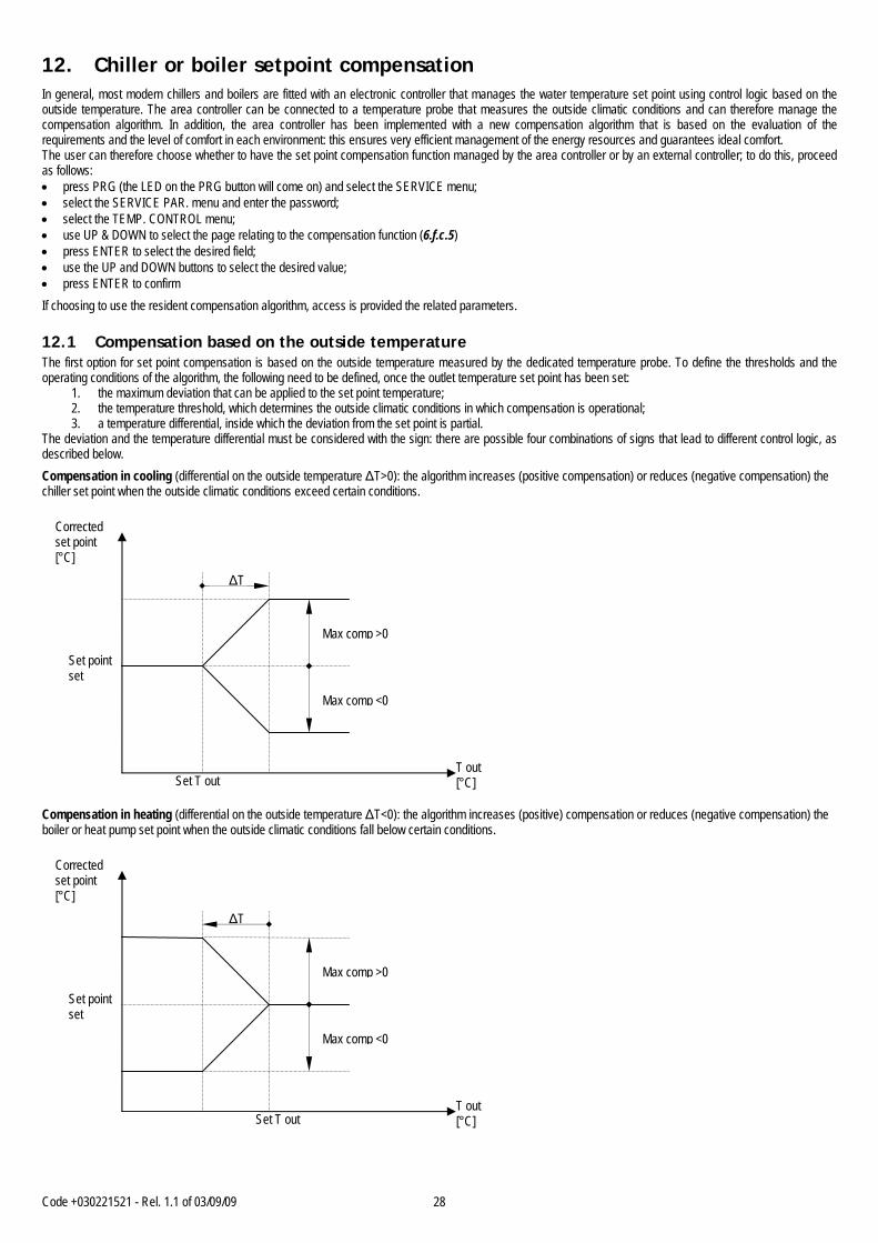
Code +030221521 - Rel. 1.1 of 03/09/09 28
12. Chiller or boiler setpoint compensation In general, most modern chillers and boilers are fitted with an electronic controller that manages the water temperature set point using control logic based on the outside temperature. The area controller can be connected to a temperature probe that measures the outside climatic conditions and can therefore manage the compensation algorithm. In addition, the area controller has been implemented with a new compensation algorithm that is based on the evaluation of the requirements and the level of comfort in each environment: this ensures very efficient management of the energy resources and guarantees ideal comfort. The user can therefore choose whether to have the set point compensation function managed by the area controller or by an external controller; to do this, proceed as follows: • press PRG (the LED on the PRG button will come on) and select the SERVICE menu; • select the SERVICE PAR. menu and enter the password; • select the TEMP. CONTROL menu; • use UP & DOWN to select the page relating to the compensation function (6.f.c.5) • press ENTER to select the desired field; • use the UP and DOWN buttons to select the desired value; • press ENTER to confirm
If choosing to use the resident compensation algorithm, access is provided the related parameters. 12.1 Compensation based on the outside temperature The first option for set point compensation is based on the outside temperature measured by the dedicated temperature probe. To define the thresholds and the operating conditions of the algorithm, the following need to be defined, once the outlet temperature set point has been set:
1. the maximum deviation that can be applied to the set point temperature; 2. the temperature threshold, which determines the outside climatic conditions in which compensation is operational; 3. a temperature differential, inside which the deviation from the set point is partial.
The deviation and the temperature differential must be considered with the sign: there are possible four combinations of signs that lead to different control logic, as described below.
Compensation in cooling (differential on the outside temperature ΔT>0): the algorithm increases (positive compensation) or reduces (negative compensation) the chiller set point when the outside climatic conditions exceed certain conditions.
Compensation in heating (differential on the outside temperature ΔT<0): the algorithm increases (positive) compensation or reduces (negative compensation) the boiler or heat pump set point when the outside climatic conditions fall below certain conditions.
Corrected set point [°C]
Max comp >0
Set T out
ΔT
T out[°C]
Set point set
Max comp <0
Corrected set point [°C]
Max comp >0
Set T out
ΔT
T out[°C]
Set point set
Max comp <0
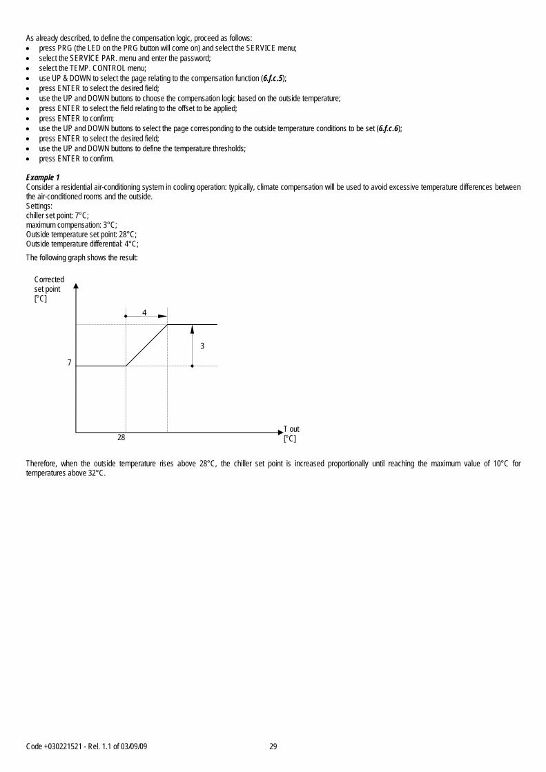
Code +030221521 - Rel. 1.1 of 03/09/09 29
As already described, to define the compensation logic, proceed as follows: • press PRG (the LED on the PRG button will come on) and select the SERVICE menu; • select the SERVICE PAR. menu and enter the password; • select the TEMP. CONTROL menu; • use UP & DOWN to select the page relating to the compensation function (6.f.c.5); • press ENTER to select the desired field; • use the UP and DOWN buttons to choose the compensation logic based on the outside temperature; • press ENTER to select the field relating to the offset to be applied; • press ENTER to confirm; • use the UP and DOWN buttons to select the page corresponding to the outside temperature conditions to be set (6.f.c.6); • press ENTER to select the desired field; • use the UP and DOWN buttons to define the temperature thresholds; • press ENTER to confirm. Example 1 Consider a residential air-conditioning system in cooling operation: typically, climate compensation will be used to avoid excessive temperature differences between the air-conditioned rooms and the outside. Settings: chiller set point: 7°C; maximum compensation: 3°C; Outside temperature set point: 28°C; Outside temperature differential: 4°C;
The following graph shows the result:
Therefore, when the outside temperature rises above 28°C, the chiller set point is increased proportionally until reaching the maximum value of 10°C for temperatures above 32°C.
Corrected set point [°C]
3
28
4
T out[°C]
7
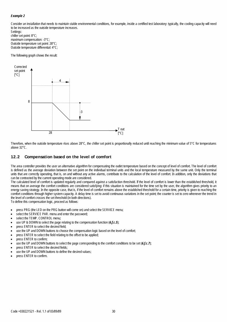
Code +030221521 - Rel. 1.1 of 03/09/09 30
Example 2 Consider an installation that needs to maintain stable environmental conditions, for example, inside a certified test laboratory: typically, the cooling capacity will need to be increased as the outside temperature increases. Settings: chiller set point: 8°C; maximum compensation: -3°C; Outside temperature set point: 28°C; Outside temperature differential: 4°C; The following graph shows the result:
Therefore, when the outside temperature rises above 28°C, the chiller set point is proportionally reduced until reaching the minimum value of 5°C for temperatures above 32°C. 12.2 Compensation based on the level of comfort The area controller provides the user an alternative algorithm for compensating the outlet temperature based on the concept of level of comfort. The level of comfort is defined as the average deviation between the set point on the individual terminal units and the local temperature measured by the same unit. Only the terminal units that are correctly operating, that is, on and without any active alarms, contribute to the calculation of the level of comfort. In addition, only the deviations that can be contrasted by the current operating mode are considered. The calculated level of comfort is updated regularly and compared against a satisfaction threshold. If the level of comfort is lower than the established threshold, it means that on average the comfort conditions are considered satisfying: if this situation is maintained for the time set by the user, the algorithm gives priority to an energy saving strategy. In the opposite case, that is, if the level of comfort remains above the established threshold for a certain time, priority is given to reaching the comfort conditions through higher system capacity. A delay time is set to avoid continuous variations in the set point; the counter is set to zero whenever the trend in the level of comfort crosses the set threshold (in both directions). To define this compensation logic, proceed as follows: • press PRG (the LED on the PRG button will come on) and select the SERVICE menu; • select the SERVICE PAR. menu and enter the password; • select the TEMP. CONTROL menu; • use UP & DOWN to select the page relating to the compensation function (6.f.c.5); • press ENTER to select the desired field; • use the UP and DOWN buttons to choose the compensation logic based on the level of comfort; • press ENTER to select the field relating to the offset to be applied; • press ENTER to confirm; • use the UP and DOWN buttons to select the page corresponding to the comfort conditions to be set (6.f.c.7); • press ENTER to select the desired fields; • use the UP and DOWN buttons to define the desired values; • press ENTER to confirm.
Corrected set point [°C]
28
4
T out[°C]
8
-3
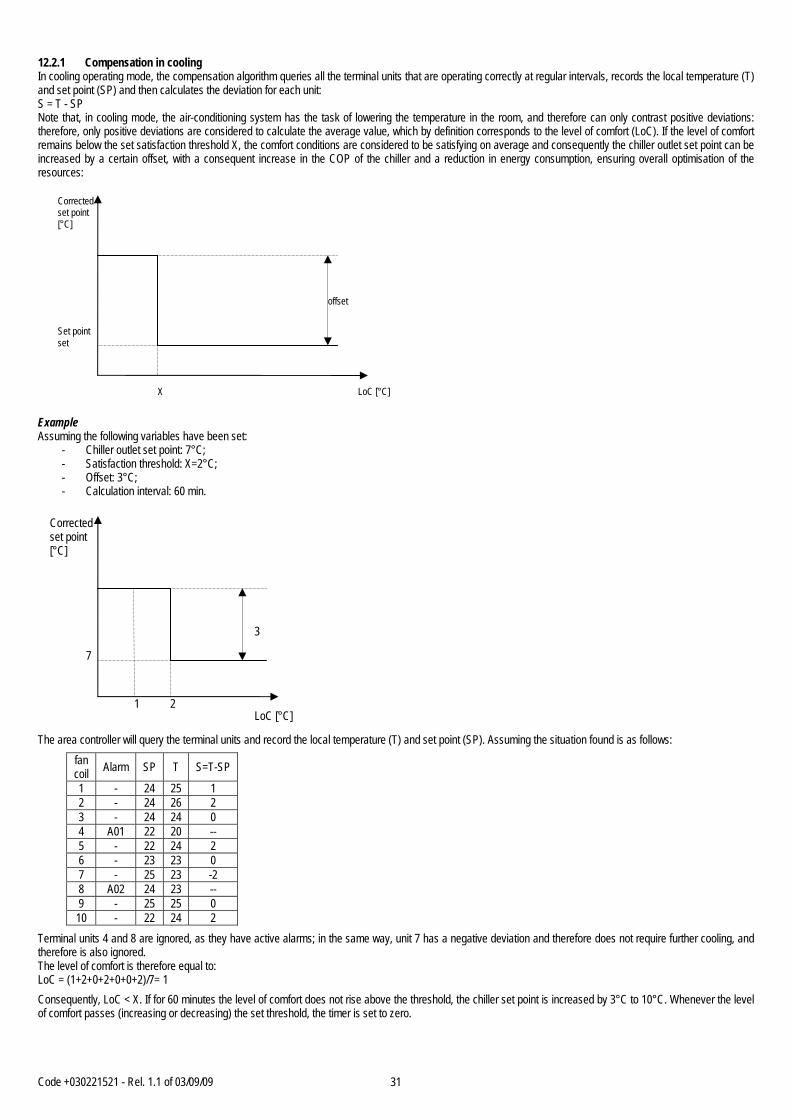
Code +030221521 - Rel. 1.1 of 03/09/09 31
12.2.1 Compensation in cooling In cooling operating mode, the compensation algorithm queries all the terminal units that are operating correctly at regular intervals, records the local temperature (T) and set point (SP) and then calculates the deviation for each unit: S = T - SP Note that, in cooling mode, the air-conditioning system has the task of lowering the temperature in the room, and therefore can only contrast positive deviations: therefore, only positive deviations are considered to calculate the average value, which by definition corresponds to the level of comfort (LoC). If the level of comfort remains below the set satisfaction threshold X, the comfort conditions are considered to be satisfying on average and consequently the chiller outlet set point can be increased by a certain offset, with a consequent increase in the COP of the chiller and a reduction in energy consumption, ensuring overall optimisation of the resources:
Example Assuming the following variables have been set:
- Chiller outlet set point: 7°C; - Satisfaction threshold: X=2°C; - Offset: 3°C; - Calculation interval: 60 min.
The area controller will query the terminal units and record the local temperature (T) and set point (SP). Assuming the situation found is as follows:
fan coil Alarm SP T S=T-SP
1 - 24 25 1 2 - 24 26 2 3 - 24 24 0 4 A01 22 20 -- 5 - 22 24 2 6 - 23 23 0 7 - 25 23 -2 8 A02 24 23 -- 9 - 25 25 0 10 - 22 24 2
Terminal units 4 and 8 are ignored, as they have active alarms; in the same way, unit 7 has a negative deviation and therefore does not require further cooling, and therefore is also ignored. The level of comfort is therefore equal to: LoC = (1+2+0+2+0+0+2)/7= 1
Consequently, LoC < X. If for 60 minutes the level of comfort does not rise above the threshold, the chiller set point is increased by 3°C to 10°C. Whenever the level of comfort passes (increasing or decreasing) the set threshold, the timer is set to zero.
3
2
LoC [°C]
Corrected set point [°C]
7
1
offset
X LoC [°C]
Corrected set point [°C]
Set point set

Code +030221521 - Rel. 1.1 of 03/09/09 32
12.2.2 Compensation in heating In heating operating mode, the compensation algorithm queries all the terminal units that are operating correctly at regular intervals, records the local temperature (T) and set point (SP) and then calculates the deviation for each unit: S = SP - T Note that, in heating mode, the air-conditioning system has the task of raising the temperature in the room, and therefore can only contrast positive deviations: therefore, only positive deviations are considered to calculate the average value, which by definition corresponds to the level of comfort (LoC). If the level of comfort remains above the set satisfaction threshold X, the comfort conditions are not considered to be satisfying on average and consequently the output of the heating system needs to be increased. The heat pump or boiler set point must therefore be increased by a certain offset:
Example Assuming the following variables have been set:
- Boiler outlet set point: 45°C; - Satisfaction threshold: X=2°C; - Offset: 5°C; - Calculation interval: 60 min.
The area controller will query the terminal units and record the local temperature (T) and set point (SP). Assuming the situation found is as follows:
fan coil Alarm SP T S=T-SP
1 - 19 16 3 2 - 19 17 2 3 - 19 15 4 4 A01 19 16 -- 5 - 19 16 3 6 - 19 17 2 7 - 19 15 4 8 A02 19 15 -- 9 - 19 16 3 10 - 19 16 3
Typically, this may be the situation in an office when the system is started again after the weekend. Terminal units 4 and 8 are ignored, as they have active alarms. The level of comfort is therefore equal to: LoC = (3+2+4+3+2+4+3+3)/8= 3
Consequently, LoC > X. If for 60 minutes the level of comfort does not fall below the threshold, the boiler or the heat pump set point is increased by 5°C to 50°C. Whenever the level of comfort passes (increasing or decreasing) the set threshold, the timer is set to zero.
5
2
LoC [°C]
Corrected set point [°C]
45
1 3
offset
t Average deviation [°C]
Corrected set point [°C]
Set point set
Code +030221521 - Rel. 1.1 of 03/09/09 33
13. Summer/Winter changeover This application can manage the changeover of system operation from cooling to heating and vice-versa. Specifically: • Cooling operation: enable the activation of the chiller in cooling mode and with corresponding compensation of the outlet temperature, send the cooling mode
signal to the terminal units; • Heating operation: enable the activation of the boiler or the chiller in heating mode (heat pump) and with corresponding compensation of the outlet temperature,
send the heating mode signal to the terminal units;
The operating mode can be switched as follows: 1. manually from the user interface; 2. from a digital input; 3. from the supervisory system; 4. from the user interface or from the supervisory system; 5. programmed changeover based on the calendar; 6. automatic changeover.
The changeover logic can be selected as follows: • press PRG (the LED on the PRG button will come on) and select the SERVICE menu; • select the SERVICE PAR. menu and enter the password; • select the TEMP. CONTROL menu; • use the UP and DOWN buttons to select the page corresponding to the selection of the operating mode (season) (6.f.c.8); • press ENTER to select the desired field; • use the UP and DOWN buttons to select the desired value; • press ENTER to confirm
The main page on the user interface always displays the active operating mode, whatever changeover mode has been selected. 13.1 Manual selection from user interface (keypad) The operating mode can be selected from the user interface as follows: • press PRG (the LED on the PRG button will come on) and select the SERVICE menu; • select the COOLING / HEATING menu (6.c); • press ENTER to select the desired field; • use the UP and DOWN buttons to select the desired operating mode; • press ENTER to confirm Alternatively, from the main page: • hold the ENTER button for at least 3 seconds, until the operating mode changes. 13.2 Manual changeover from digital input (ID4) In changeover from digital input is selected, the corresponding electromechanical circuit needs to be wired. When closing/opening the contact, the system changes the operating mode:
- contact open heating operation; - contact closed cooling operation.
13.3 Changeover from supervisory system If this logic is selected, changeover is managed by the supervisory system. The changeover control signal is transmitted via serial communication using the variable with address 30, as follows:
- 1 heating operation; - 0 cooling operation.
13.4 Programmed changeover based on the calendar The area controller allows the date to be defined for changing the operating mode. To do this, proceed as follows: • press PRG (the LED on the PRG button will come on) and select the SERVICE menu; • select the SERVICE PAR. menu and enter the password; • select the TEMP. CONTROL menu; • use the UP and DOWN buttons to select the page corresponding to changeover based on the calendar (IMPORTANT: the page can only be displayed if the
AUTO MODE changeover option has been selected) (6.f.c.9); • press ENTER to select the desired field; • use the UP and DOWN buttons to select the desired value; • press ENTER to confirm
Code +030221521 - Rel. 1.1 of 03/09/09 34
13.5 Automatic changeover The area controller allows the previous changeover mode to be integrated with the reading of the outside temperature probe: therefore, the changeover from one operating mode to the other will take place when, after a set date, the outside climate conditions are suitable. The setting procedure is described below: • press PRG (the LED on the PRG button will come on) and select the SERVICE menu; • select the SERVICE PAR. menu and enter the password; • select the TEMP. CONTROL menu; • use the UP and DOWN buttons to select the page corresponding to changeover based on the calendar (IMPORTANT: the page can only be displayed if the
AUTO MODE changeover option has been selected) (6.f.c.9); • press ENTER to select the desired field; • use the UP and DOWN buttons to select the desired value; • press ENTER to confirm 14. Management of the dehumidification function The dehumidification algorithm distinguishes between cooling and heating operation. 14.1 Dehumidification in cooling mode If the system is operating in cooling mode, a set point can be defined for the relative humidity in the rooms. The area controller compares this set point against the value measured by the connected humidity probes. One humidity probe can be connected for each water line. If the relative humidity in the rooms managed by a water line is greater than the set point, all the devices connected to the line are switched to DRY mode: this means the chiller set point is forced to the minimum value and the mixing valve in the water line is fully opened. The controllers on the terminal units in DRY mode operate the fan at minimum value. Each water line is managed independently; all the devices belonging to one water line behave in the same way. To set the parameters relating to the management of the dehumidification function, proceed as follows: • press the PRG button (the LED on the PRG button will come on) and select the SET POINT menu; • use the UP and DOWN buttons to select the page corresponding to the relative humidity set point setting (2.d); • press ENTER to select the desired field; • use the UP and DOWN buttons to select the desired value; • press ENTER to confirm 14.2 Dehumidification in heating mode If the system is operating in heating mode, the dehumidification function is only allowed when the installation is fitted with an independent dehumidifier. The dehumidification function must be managed manually by the user via the terminal unit user interface, by selecting the DRY function. This request is processed by the area controller, which enables a dedicated digital output to switch the dehumidifier on or off. 15. Manual management of the outputs The MANUAL menu, password protected, allows the user or manually control the main outputs: • press PRG (the LED on the PRG button will come on) and select the SERVICE menu; • select the MANUAL menu and enter the password; • press ENTER to select the desired field; • use the UP and DOWN buttons to select the desired value; • press ENTER to confirm. It is strongly recommended to only use this option to check the correct operation of a connected device.
Code +030221521 - Rel. 1.1 of 03/09/09 35
16. Supervisor The area controller can interface with a local or remote supervisory/telemaintenance system. The pCO* board accessories include various optional serial communication boards (for the installation of the optional serial communication boards, see the pCO* board installation manual): - RS485 for communication with Modbus, Carel protocols; - pCOWeb for communication via Ethernet with BACnet (Ethernet and IP), SNMP, XML, HTML, e-mail; - pCOnet for communication with BACnet MS/TP protocol; - LonWorks; - Trend; - RS232 for communication via GSM or analogue modem; - KNX. This application can communicate with a supervisory system with the Modbus protocol via an RS485 interface; the Carel software supervisory systems, PlantVisor PRO, features a dedicated page for communication with this application. To set the communication parameters, proceed as follows: • press PRG (the LED on the PRG button will come on) and select the SERVICE menu; • select the BMS CONFIGURATION menu (6.c); • press ENTER to select the desired field; • use the UP and DOWN buttons to select the desired value; • press ENTER to confirm. If the settings are correct (serial address and communication speed), the parameters shown in the following table will be sent by the unit. Setting the serial identification number to 0 disables serial communication with the supervisory system. The number of variables is limited; so it is necessary use a variable like switch and read the data regarding each single fancoil. The adress of this variable is: I 1 Fan_Coil Selection [1..100] The variables, that can be swithched, will be indicated in bold carachter in the follows table. Below is the list of the variables shared with the supervisory system. 16.1 List of analogue variables Type Address Description R/W A 1 Outside temperature R A 2 Boiler temperature R A 3 Outlet temperature line 1 R A 4 Outlet temperature line 2 R A 5 Outlet temperature line 3 R A 6 Humidity line 1 R A 7 Humidity line 2 R A 8 Humidity line 3 R A 9 --- --- A 10 Pump line 1 R A 11 Pump line 2 R A 12 Pump line 3 R A 13 Chiller set point R A --- --- A 25 Virtual probe [fancoil] R A 26 Probe value ST2 of control [fancoil] R A 27 Probe value ST3 of control [fancoil] R A 28 Probe humidity SCH_TH [fancoil] R A 29 Temperature probe value SCH_TH [fancoil] R A 30 Set point fan coil 1 R A 31 T room fan coil 1 R A 32 Set point fan coil 2 R A 33 T room fan coil 2 R A … …… R A 230 Set point fan coil 100 R A 231 T room fan coil 100 R
Code +030221521 - Rel. 1.1 of 03/09/09 36
List of integer variables Type Address Description R/W I 1 Fan_Coil Selection [1..100] R/W --- --- I 50 Working mode (freddo, caldo, caldo + res , vent., off) [fancoil] R/W I 51 Number active local alarm (0 = no alarm). If at the same time will be show the
hightest priority alarm. Can contain also the slave alarms. R
I 52 Fancoil master or slave (in single node configuration) R I 53 Activation function SLEEP / ECONOMY R/W I 54 Offset setpoint if COMFORT function is active R/W I 55 ON/OFF state of control R/W I 56 Digital Input state R I 57 Regulation setpoint R/W I 58 Operation setpoint R --- --- I 101 ON-OFF fancoil 1 R I 102 ON-OFF fancoil 2 R … …… R I 200 ON-OFF fancoil 100 R 16.2 List of digital variables Type Address Description R/W D 1 Pump 1 thermal overload R D 2 Pump 2 thermal overload R D 3 Pump 3 thermal overload R D 4 COOLING / HEATING changeover R D 5 Generic chiller alarm R D 6 Generic boiler alarm R D 7 High water circuit pressure R D 8 Remote ON – OFF R D 9 --- --- D 20 Pump line 1 R D 21 Pump line 2 R D 22 Pump line 3 R D 23 On/Off Chiller R D 24 On/Off Boiler R D 25 Cooling– Heating R D 26 --- --- D 27 Alarm R D --- --- D 30 Cooling – Heating selection from BMS R/W D --- --- D 50 State digital input request heat R D 51 State digital input request cold R D 52 State digital input busy R D --- D 101 Alarm on fan coil 1 R D 102 Alarm on fan coil 2 R D 103 Alarm on fan coil 3 R D … …… R D 200 Alarm on fan coil 100 R

Code +030221521 - Rel. 1.1 of 03/09/09 37
17. Alarms The area controller collects the information relating to the alarms on all the connected devices and signals these to the user. In general, when an alarm is activated, the red LED is activated on the area controller user terminal and an OFF command is sent to the device in question; pressing the ALARM button on the area controller user terminal displays the available information relating to the alarm in progress. 17.1 Table of alarms
Order Description Chiller OFF
Boiler OFF
Pump OFF
A.C. OFF
Fan coil OFF
Reset Auto / Man
Delay
1 Clock board not available or disconnected
NO NO NO NO NO Manual Settable
2 Memory expansion error. NO NO NO NO NO Manual Settable 3 Boiler probe broken or
disconnected. NO NO NO NO NO Manual Settable
4 Outlet 1 probe broken or disconnected.
NO NO NO NO NO Manual Settable
5 Outlet 2 probe broken or disconnected.
NO NO NO NO NO Manual Settable
6 Outlet 3 probe broken or disconnected.
NO NO NO NO NO Manual Settable
7 Outside temperature probe broken or disconnected
NO NO NO NO NO Manual Settable
8 Humidity 1 probe broken or disconnected.
NO NO NO NO NO Manual Settable
9 Humidity 2 probe broken or disconnected.
NO NO NO NO NO Manual Settable
10 Humidity 3 probe broken or disconnected.
NO NO NO NO NO Manual Settable
11 Pump 1 overload OFF OFF OFF NO NO Manual Settable 12 Pump 2 overload OFF OFF OFF NO NO Manual Settable 13 Pump 3 overload OFF OFF OFF NO NO Manual Settable 14 Chiller alarm YES NO ON ON OFF Manual Settable 15 Boiler alarm NO YES ON ON OFF Manual Settable 16 High water temperature
alarm YES YES YES YES NO Manual Settable
17 High temperature alarm NO YES YES YES ON Manual Settable 18 Fan coil with same
address alarm NO NO NO NO NO Manual Settable
19 Fan coil offline. NO NO NO NO NO Manual Settable 20 Fan coil local alarm NO NO NO NO NO Manual Settable 21 Pump 1 hour counter
alarm NO NO NO NO NO Manual Settable
22 Pump 2 hour counter alarm
NO NO NO NO NO Manual Settable
23 Pump 3 hour counter alarm
NO NO NO NO NO Manual Settable
24 Chiller hour counter alarm NO NO NO NO NO Manual Settable 25 Boiler hour counter alarm NO NO NO NO NO Manual Settable 17.2 Alarm log The LOG menu provides the user the log of alarm events, including the type of alarm and event date. To display the menu, proceed as follows: • press the PRG button (the LED on the PRG button will come on) and select the LOG menu (5); • use the UP and DOWN buttons to scroll the list of events. To delete the alarm log, proceed as follows: • press PRG (the LED on the PRG button will come on) and select the SERVICE menu; • select the SERVICE PAR. menu; • enter the correct password; • select the RESET LOG menu (6.f.d); • press ENTER to select the RESET LOG field and set YES • press ENTER to confirm.


CAREL S.p.A. Via dell’Industria, 11 - 35020 Brugine - Padova (Italy) Tel. (+39) 049.9716611 Fax (+39) 049.9716600 http://www.carel.com - e-mail: [email protected]
Codd
.+03
0221
521-
rel.
1.0
- 14.
06.2
007
Agency


![Tav[1].Rel a00 Relazione](https://img.pdfslide.net/doc/110x75/55721435497959fc0b9405ec/tav1rel-a00-relazione.jpg)
![Lect 1 Areas Regionales Y Rel[1]](https://img.pdfslide.net/doc/110x75/55ad1d5e1a28ab83238b46bb/lect-1-areas-regionales-y-rel1.jpg)