Embed Size (px)
Citation preview
03 STRUCTURE 0331b Brick and block construction
© NATSPEC 1 "[Insert date]"
0331B BRICK AND BLOCK CONSTRUCTION
Worksection application
This worksection Template is applicable to internal and external, load bearing and non-load bearing brick and block construction in buildings and associated structures using manufactured units comprising clay, calcium silicate, concrete or autoclaved aerated concrete (AAC) used in buildings and associated structures. It includes details on mortar, reinforcement, ties and other accessories, lintels, damp proofing and flashings.
Guidance text
All text within these boxes is provided as guidance for developing this worksection and should not form part of the final specification. This Guidance text may be hidden or deleted from the document using the NATSPEC Toolbar or the hidden text Hide and Delete functions of your word processing system. For additional information visit FAQs at www.natspec.com.au.
Optional text Text in this font (blue with a grey background) covers items specified less frequently. It is provided for incorporation into Open text where it is applicable to a project.
Related material located elsewhere in NATSPEC If a listed worksection is not part of your subscription package and you wish to purchase it, contact NATSPEC.
Related material may be found in other worksections. See for example:
• Adhesives, sealants and fasteners for sealants in external masonry joints.
• Termite management.
• ANCON structural steel components.
• Monolithic stabilised earth walls.
• Mud brick walls.
• Stone masonry.
• Sheet flooring and decking, for holding down requirements against wind uplift.
• Roofing – combined, for holding down requirements against wind uplift.
• Partitions – brick and block, for interior fitout masonry walls.
• Rendering and plastering.
Cross references
Worksections that cross reference this worksection are:
• Green star – as built submissions.
• Green star – office as built submissions.
• Adhesives, sealants and fasteners.
Material not included in NATSPEC Some projects may include items not covered by NATSPEC. For these you may need to create new text or modify this text or a suitable worksection.
Documenting this and related work You may document this and related work as follows:
• Brickwork and blockwork is normally fully detailed. See AS 3700 clause 1.4 for information to be provided.
• For masonry in small buildings, AS 4773 may be used. See AS 4773.1 clause 1.4 for minimum information to be provided.
• Document details related to durability, fire resistance, masonry growth, differential movements, earthquake and wind design, lateral stability design and robustness.
Specifying ESD
Refer to the NATSPEC TR 01 - Specifying ESD. The following may be specified in the worksection:
• Durability classification for steel components, including reinforcement.
03 STRUCTURE 0331b Brick and block construction
© NATSPEC 2 "[Insert date]"
1 GENERAL
1.1 RESPONSIBILITIES
General Requirement: Provide brick and block construction, as documented. Documented is defined in the General requirements worksection as meaning contained in the contract documents.
1.2 CROSS REFERENCES
General Requirement: Conform to the following worksection(s): - General requirements. The General requirements worksection contains umbrella requirements for all building and services worksections.
- [complete/delete] List the worksections cross referenced by this worksection. The General requirements worksection references the Common requirements subgroup of worksections. It is not necessary to repeat them here. However, you may also wish to direct the contractor to other worksections where there may be work that is closely associated with this work.
NATSPEC uses generic worksection titles, whether or not there are branded equivalents. If you use a branded worksection, change the cross reference here.
See Related material located elsewhere in NATSPEC in the introduction Guidance.
1.3 STANDARDS
General Materials and construction: To AS 3700. AS 3700 Section 3 covers design properties for masonry units, masonry, ties and accessories, grout, reinforcement and tendons. AS 3700 Section 11 covers general requirements of masonry, masonry units, mortar, wall ties, connectors, accessories, lintels, damp-proof courses, flashings, weatherings, grout, reinforcement and tendons.
AS 3700 Section 12 covers both general requirements for construction and requirements for special masonry.
CMAA publications CMAA MA45, CMAA MA54 and CMAA MA55 available from www.cmaa.com.au provide more information on concrete masonry.
Various publications of the Clay Brick and Paver Institute (CBPI) are of general application, particularly Think Brick Manual 02 and Think Brick Manual 09.
For works including building designs conforming to AS 4773, amend with the following Optional text:
Materials and construction: To AS 3700 or AS 4773, as appropriate.
For restoration work, see also BS 6576 on rising damp in walls and the installation of chemical damp-proof courses.
Only particular requirements for the project should be added to this worksection.
INTERPRETATION
This clause is not included in this basic version. The full worksection is part of the BUILDING Professional package.
1.4 INSPECTION
Notice Inspection: Give notice so that inspection may be made of the following: - Set out. - Unit type, colour and texture. - Bottoms of cavities, after cleaning out. - Bottoms of core holes, before grouting. - Reinforcement type and diameter. - Positioning of reinforcing before grouting. - Control joints, ready for insertion of joint filler. - Damp-proof courses, in position. - Flashings, in position. - Lintels, in position. - Structural steelwork, including bolts and shelf angles, in position.

03 STRUCTURE 0331b Brick and block construction
© NATSPEC 3 "[Insert date]"
Amend to suit the project adding critical stage inspections required.
Hold points, if required, should be inserted here.
1.5 TOLERANCES
General Requirement: To AS 3700 Table 12.1. Specify more stringent tolerances for specific architectural requirements including facework. Consider adding facework tolerances for the horizontality, regularity and verticality of edges, joints etc.
SUBMISSIONS
This clause is not included in this basic version. The full worksection is part of the BUILDING Professional package.
2 PRODUCTS
2.1 DURABILITY
General Exposure environment: [complete/delete] Select exposure environment from: mild, moderate, industrial, marine or severe marine to AS 3700 clause 5.3. Exposure environment is project specific and applies to all masonry materials, accessories and built-in items.
For building designs conforming to AS 4773, see AS 4773.1 clause 4.3.
Exposure locations: To AS 3700 clause 5.4. There might be different exposure locations within one project: exterior, exterior-coated or interior. Nominate in SELECTIONS or show on the drawings. Refer to NATSPEC TECHnote DES 010 for information on atmospheric corrosivity categories for ferrous products.
For building designs conforming to AS 4773, amend with the following Optional text:
Exposure locations: To AS 4773 clause 4.3.
2.2 MATERIALS
Brick and block units Selections: As documented in the Brick and block construction schedule. Document the name, type, category, size and fire rating of masonry units in SELECTIONS or show in the drawings.
Identify face units either as a proprietary item (brand name, manufacturer) or by reference to preselected samples. These remarks also apply to selected commons specified to be used as face bricks. Preferably use clay commons with clay face units. If using different types in close proximity, e.g. in the two leaves of a cavity wall, make sufficient provision for differential movement between them.
Standard: To AS/NZS 4455.1 and AS/NZS 4455.3. Salt attack resistance grade: To AS 3700 Table 5.1. Use AS 3700 Table 5.1 to select the salt attack resistance grade (protected, general purpose or exposure) for different exposure locations within the project and nominate in SELECTIONS. Problems are being experienced with salt attack on masonry below damp-proof course level on sites which had once been heavily fertilised. Exposure class masonry units are normally readily available for such locations.
The means for demonstrating conformance with the required salt attack resistance grade of masonry units is given in AS/NZS 4455.1 and AS/NZS 4455.3
For works including building designs conforming to AS 4773, amend with the following Optional text:
Salt attack resistant grade: To AS 3700 Table 5.1 or AS 4773.2 Table 2.1, as appropriate. Minimum age of clay bricks: 7 days. The strength values used in the masonry design are based on an age of 7 days. Refer to Think Brick Manual 10 for further information about the minimum age of clay bricks.
Mortar materials Mortar class: To AS 3700 Table 5.1. Use AS 3700Table 5.1 to select mortar class (M1 to M4) for different exposure locations within the project and nominate in SELECTIONS or show on the drawings.
03 STRUCTURE 0331b Brick and block construction
© NATSPEC 4 "[Insert date]"
Consider the benefits of adopting one class of mortar for the project versus the cost of using a higher class of mortar than would normally be required for internal work. Consider soil conditions and other exposure issues carefully.
Cement: To AS 3972. - Type: [complete/delete] Cement type is normally GP. Refer to AS 3972 for other types of cements. Consider using Type GB or Type GL cement if fly ash additions are favourable or Type SR for possible sulphate attack protection.
Refer to AS 1316, if masonry cement is used.
White cement: With ≤ 1% iron salts content. Lime: To AS 1672.1. Sand: Fine aggregate with a low clay content and free from efflorescing salts, selected for colour and grading. Refer to CCAA T60 for guidance on sand in mortar. If possible, mortar colour should be achieved by the natural colour of the sand (including blended sands), if necessary in combination with white or off-white cement, rather than by the addition of colouring pigments.
Water: Clean and free from any deleterious matter. Admixtures: To AS 3700 clause 11.4.2.4. For works including building designs conforming to AS 4773, amend with the following Optional text:
Admixtures: To AS 3700 clause 11.4.2.4 or AS 4773.2 clause 3.2.6, as appropriate.
Plasticisers are not recommended as a substitute for lime. A CBPI survey found that bricklayers routinely add between 4 and 20 times the recommended amount, resulting in low bond strength and durability. Specify limits to suit the project.
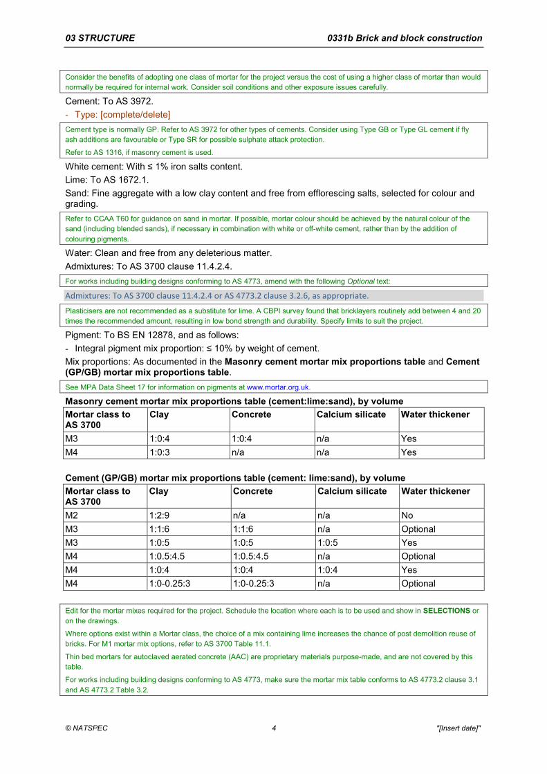
Pigment: To BS EN 12878, and as follows: - Integral pigment mix proportion: ≤ 10% by weight of cement. Mix proportions: As documented in the Masonry cement mortar mix proportions table and Cement (GP/GB) mortar mix proportions table. See MPA Data Sheet 17 for information on pigments at www.mortar.org.uk.
Masonry cement mortar mix proportions table (cement:lime:sand), by volume Mortar class to AS 3700
Clay Concrete Calcium silicate Water thickener
M3 1:0:4 1:0:4 n/a Yes M4 1:0:3 n/a n/a Yes Cement (GP/GB) mortar mix proportions table (cement: lime:sand), by volume Mortar class to AS 3700
Clay Concrete Calcium silicate Water thickener
M2 1:2:9 n/a n/a No M3 1:1:6 1:1:6 n/a Optional M3 1:0:5 1:0:5 1:0:5 Yes M4 1:0.5:4.5 1:0.5:4.5 n/a Optional M4 1:0:4 1:0:4 1:0:4 Yes M4 1:0-0.25:3 1:0-0.25:3 n/a Optional Edit for the mortar mixes required for the project. Schedule the location where each is to be used and show in SELECTIONS or on the drawings.
Where options exist within a Mortar class, the choice of a mix containing lime increases the chance of post demolition reuse of bricks. For M1 mortar mix options, refer to AS 3700 Table 11.1.
Thin bed mortars for autoclaved aerated concrete (AAC) are proprietary materials purpose-made, and are not covered by this table.
For works including building designs conforming to AS 4773, make sure the mortar mix table conforms to AS 4773.2 clause 3.1 and AS 4773.2 Table 3.2.
03 STRUCTURE 0331b Brick and block construction
© NATSPEC 5 "[Insert date]"
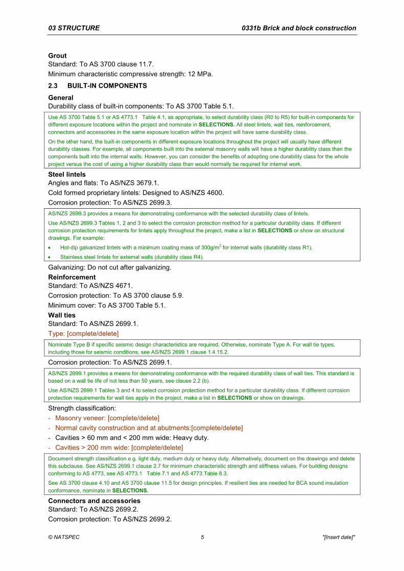
Grout Standard: To AS 3700 clause 11.7. Minimum characteristic compressive strength: 12 MPa.
2.3 BUILT-IN COMPONENTS
General Durability class of built-in components: To AS 3700 Table 5.1. Use AS 3700 Table 5.1 or AS 4773.1 Table 4.1, as appropriate, to select durability class (R0 to R5) for built-in components for different exposure locations within the project and nominate in SELECTIONS. All steel lintels, wall ties, reinforcement, connectors and accessories in the same exposure location within the project will have same durability class.
On the other hand, the built-in components in different exposure locations throughout the project will usually have different durability classes. For example, all components built into the external masonry walls will have a higher durability class than the components built into the internal walls. However, you can consider the benefits of adopting one durability class for the whole project versus the cost of using a higher durability class than would normally be required for internal work.
Steel lintels Angles and flats: To AS/NZS 3679.1. Cold formed proprietary lintels: Designed to AS/NZS 4600. Corrosion protection: To AS/NZS 2699.3. AS/NZS 2699.3 provides a means for demonstrating conformance with the selected durability class of lintels.
Use AS/NZS 2699.3 Tables 1, 2 and 3 to select the corrosion protection method for a particular durability class. If different corrosion protection requirements for lintels apply throughout the project, make a list in SELECTIONS or show on structural drawings. For example:
• Hot-dip galvanized lintels with a minimum coating mass of 300g/m2 for internal walls (durability class R1).
• Stainless steel lintels for external walls (durability class R4).
Galvanizing: Do not cut after galvanizing. Reinforcement Standard: To AS/NZS 4671. Corrosion protection: To AS 3700 clause 5.9. Minimum cover: To AS 3700 Table 5.1. Wall ties Standard: To AS/NZS 2699.1. Type: [complete/delete] Nominate Type B if specific seismic design characteristics are required. Otherwise, nominate Type A. For wall tie types, including those for seismic conditions, see AS/NZS 2699.1 clause 1.4.15.2.
Corrosion protection: To AS/NZS 2699.1. AS/NZS 2699.1 provides a means for demonstrating conformance with the required durability class of wall ties. This standard is based on a wall tie life of not less than 50 years, see clause 2.2 (b).
Use AS/NZS 2699.1 Tables 3 and 4 to select corrosion protection method for a particular durability class. If different corrosion protection requirements for wall ties apply in the project, make a list in SELECTIONS or show on drawings.
Strength classification: - Masonry veneer: [complete/delete] - Normal cavity construction and at abutments:[complete/delete] - Cavities > 60 mm and < 200 mm wide: Heavy duty. - Cavities > 200 mm wide: [complete/delete] Document strength classification e.g. light duty, medium duty or heavy duty. Alternatively, document on the drawings and delete this subclause. See AS/NZS 2699.1 clause 2.7 for minimum characteristic strength and stiffness values. For building designs conforming to AS 4773, see AS 4773.1 Table 7.1 and AS 4773 Table 8.3.
See AS 3700 clause 4.10 and AS 3700 clause 11.5 for design principles. If resilient ties are needed for BCA sound insulation conformance, nominate in SELECTIONS.
Connectors and accessories Standard: To AS/NZS 2699.2. Corrosion protection: To AS/NZS 2699.2.
03 STRUCTURE 0331b Brick and block construction
© NATSPEC 6 "[Insert date]"
AS/NZS 2699.2 provides a means for demonstrating conformance with the required durability class of connectors and accessories, including masonry anchors, fixings and tie-downs.
Use AS/NZS 2699.2 Table 1 and AS/NZS 2699.2 Table 2 to select corrosion protection method for a particular durability class. If different corrosion protection requirements for connectors and accessories apply throughout the project, make a list in SELECTIONS or show on drawings.
Design criteria for flexible masonry ties: [complete/delete] If accommodation of movement is required at control joints and where masonry abuts structural elements such as column faces and slab soffits, document here. Alternatively, document on the drawings and delete this subclause.
If selection is left to the builder, provide requirements for movement and associated load transfer. See AS 3700 section 10 for detailing of masonry for earthquake loads.
Flashings and damp-proof courses Standard: To AS/NZS 2904. For works including building designs conforming to AS 4773, see AS 4773.2 Table 5.2 for suitable materials for flashings and damp-proof courses.
Slip joints Standard: To AS 3700 clause 4.13. Material: [complete/delete] Preferably show on the drawings. Alternately show the slip joint material here. Make careful selection in case of masonry walls supporting exposed concrete slabs. Coordinate with the Concrete – combined or Concrete in situ worksection.
3 EXECUTION
3.1 GENERAL
Mortar mixing General: Measure volumes accurately to the documented proportions. Machine mix for at least six minutes. Think Brick Manual 10 provides detailed information on mortar mixing.
Protection from contamination General: Protect masonry materials and components from ground moisture and contamination. Bond Type: Stretcher bond. Other options include English, Flemish, stack, or running 100 mm stagger for AAC units. For existing work you may wish to include the following Optional text:
Existing work: Rod and bond to match existing. Building in Embedded items: Build in wall ties and accessories as the construction proceeds. If it is not practicable to obtain the required embedment wholly in the mortar joint in hollow masonry units, fill appropriate cores with grout or mortar. Steel door frames: Fill the backs of jambs and heads solid with mortar as the work proceeds. Heads of some steel door frames may be used as lintels. Consult manufacturer.
Clearance for timber frame shrinkage General: In timber frame brick veneer construction, leave clearances between window frames and brick sill and between roof frames and the brick veneer as follows: - Additional clearance: To accommodate additional shrinkage of unseasoned floor timbers. - Single storey frames and ground floor windows (not for slab on ground): 10 mm. - Two storey frames and upper floor windows: 20 mm. Construction at different rates or times Monolithic structural action: If two or more adjoining sections of masonry, including intersecting walls, are constructed at different rates or times, rake back or tie the intersections between those sections so that monolithic structural action is obtained in the completed work.
03 STRUCTURE 0331b Brick and block construction
© NATSPEC 7 "[Insert date]"
Joining to existing General: Provide a control joint where joining to existing structures. Do not tooth new masonry into existing work unless approved by a professional engineer. If differential movement across the vertical control joint is expected, the joint should be detailed (e.g. with flexible masonry anchors) by the structural engineer. See AS 3700 clause 12.4.10. Toothing-in may be acceptable in some situations e.g. infilling an existing window opening, with the approval of the structural engineer.
Mortar joints Solid and cored units: Lay on a full bed of mortar. Fill perpends solid. Cut mortar flush. Face-shell bedded hollow units: Fill perpends solid. Cut mortar flush. Finish: Conform to the following: - Externally: Tool to give a dense water-shedding finish. - Internally: If wall is to be plastered, do not rake more than 10 mm to give a key. - Thickness: 10 mm. Cutting: Set out masonry with joints of uniform width and minimum cutting of masonry units. For mortar jointing, see AS 3700 clauses 4.9.
Monolithic structural action Header units: Except in stretcher bond facework, provide brick and block header units, to AS 3700 clause 4.11.2. Spacing: 600 mm maximum. Location: Provide header units in the following locations: - At engaged piers. - At engagement of diaphragms with the leaves in diaphragm walls. - At intersections of flanges with shear walls. - At intersections with supporting walls and buttresses. - Between leaves in solid masonry construction. Rate of construction General: Regulate the rate of construction to eliminate joint deformation, slumping or instability. Rods Set out: Construct masonry to the following rods: - 75 mm high units: 7 courses to 600 mm. - 90 mm high units: 6 courses to 600 mm. - 190 mm high units: 3 courses to 600 mm. For work to aerated autoclaved concrete blocks and perforated clay blocks, refer to manufacturer's details.
Protection General: Cover the top surface of brickwork and blockwork to prevent the entry of rainwater and contaminants. Single leaf and solid walls: Moisture protection to AS 3700 clause 4.7.4. Protect single leaf and solid walls to AS 3700 clause 4.7.4.
Temporary support General: If the final stability of the masonry is dependent on construction of (structural) elements after the brickwork and blockwork is completed, provide proposals for temporary support or bracing.
3.2 FACEWORK
Cleaning Appropriate detailing, protection, careful finishing and progressive cleaning reduces the need for subsequent cleaning. AS 4773.2 Appendix B, provides extensive guidance on this topic. Choice of correct cleaning method is the contractor’s responsibility.
General: Clean progressively as the work proceeds to remove mortar smears, stains and discolouration. Do not erode joints if using pressure spraying. Acid solution: Do not use.
03 STRUCTURE 0331b Brick and block construction
© NATSPEC 8 "[Insert date]"
Only specify acid cleaning as a last resort. Acids can damage mortar joints, metal and plastic items, such as window frames and damp-proof courses. Incorrect acid cleaning can also cause secondary staining in the future.
See also Think Brick Manual 03, CMAA MA41 and The brick cleaning manual for further guidance on other types of masonry cleaning. If you choose to document acid cleaning, replace the above with the following Optional text:
Acid solution: Strictly follow the manufacturer’s recommendations and AS 4773.2 Appendix B. Colour mixing Distribution: In facework, distribute the colour range of units evenly to prevent colour concentrations and banding. Below ground Facework: Commence face brickwork at least 1 full course for blockwork, or 2 full courses for brickwork, below adjacent finished surface level. Delete or amend if facework commences at a higher level.
Double face walls Selection: Select face units for uniform width and double-face qualities. Preferred face: Before starting, obtain approval of the preferred wall face, and favour that face should a compromise be unavoidable. Delete if shown on the drawings.
Perpends General: If other than vertically aligned perpends in alternate courses are proposed, provide details. Delete if already covered on the drawings.
Sills and thresholds General: Solidly bed sills and thresholds and lay them with the top surfaces draining away from the building. Minimum size of cut unit: Three quarters full width. Add here clauses specifying other trim items, if required; e.g. copings, string courses, corbel courses, parapets, if not shown on the drawings.
Sill units: Detail or schedule on the drawings (e.g. squint bricks, brick on edge, purpose-made blocks, tiles).
Threshold units: Detail or schedule on the drawings. Schedule type of unit (e.g. brick on edge, purpose-made blocks, tiles).
3.3 SUBFLOOR WORK
Delete this clause if the building does not have a subfloor area. Otherwise, show support layout for the suspended floor on the drawings and coordinate with the Sheet flooring and decking worksection.
Access openings General: In internal walls, leave door width openings beneath doorways to give access to underfloor areas. Air vent locations General: Provide air vents to give adequate cross ventilation to the space under suspended ground floors. See also AS 1860.2 clause 5 on subfloor ventilation. Air vents may also be used for cavity ventilation at, say, 2000 mm2 free area per metre run of storey-height brickwork.
For subfloor ventilation, BCA F1.12 and BCA Table F1.12 provides minimum requirements for various climates. For building designs conforming to AS 4773, see also AS 4773.2 clause 6.2.
See AS 3959 for building in bushfire prone areas; vents require a corrosion resistant wire mesh to prevent ingress of embers.
Cavity walls: Provide matching vents in the internal leaves located as near as practicable to the vents in the external leaves. Location: Below damp-proof course to internal and external walls. Show on the drawings. Location of air vents is often a critical design issue.
Air vent types Blockwork: Select from the following: - Concrete framed: Bronze wire mesh in concrete frame 390 x 190 mm. - Vent blocks: Purpose-made vent blocks.
03 STRUCTURE 0331b Brick and block construction
© NATSPEC 9 "[Insert date]"
Brickwork: Select from the following: - Concrete framed: Bronze wire mesh in concrete frames, 470 x 160 mm. - Cut brick: 2 cut bricks laid vertically and evenly spaced in a 230 mm wide x 2 course high opening,
backed with bronze wire mesh built in. - Terra cotta: Perforated, 230 x 160 mm. Underpinning Requirement: Install underpinning while maintaining the building undamaged. Grouting: Pack dry mix M4 mortar between underpinning and existing structure at the completion of each panel of underpinning. Confirm with the structural engineer and amend as required.
3.4 CAVITY WORK
Cavity clearance General: Keep cavities clear at all times. Cavity fill General: Fill the cavity with mortar to 1 course above adjacent finished (ground) level. Fall the top surface towards the outer leaf. Cavity width General: Provide minimum cavity widths in conformance with the following: - Masonry walls: 50 mm. - Masonry veneer walls: 40 mm between the masonry leaf and the load bearing frame and 25 mm
minimum between the masonry leaf and sheet bracing. Delete if shown on the drawings or amend to suit.
Openings Care: Do not close the cavity at the jambs of external openings. Delete if drawings indicate closed cavities.
Wall ties connectors and accessories Protection: Install to prevent water passing across the cavity. For information on vapour barriers refer to NATSPEC TECHnote DES 004.
3.5 DAMP-PROOF COURSES
See AS 3700 clause 11.6.2 for mortar weatherings. The use of damp-resisting additives is not recommended; they are not listed in AS 3700 clause 11.4.2.4. See AS 3700 clause 4.7.3 and AS 3700 11.6. BCA F1.9(b) permits two options for damp-proof courses: to AS/NZS 2904 or impervious termite shields to AS 3660.1. This is varied in South Australia to address the effects of salt damp.
Location The defaults are not comprehensive. Typical damp-proof course and flashing applications should be shown on the drawings. If they are, delete the following as appropriate. Coordinate damp-proof courses with slip joints and with termite shields.
General: Provide damp-proof courses as follows: - Timber floors: In the first course below the level of the underside of ground floor timbers in internal
walls and inner leaves of cavity walls. - Cavity walls built off slabs on ground: In the bottom course of the outer leaf, continuous horizontally
across the cavity and up the inner face bedded in mortar, turned 30 mm into the inner leaf 1 course above.
- Masonry veneer construction: In the bottom course of the outer leaf, continuous horizontally across the cavity. Fasten to the inner frame 75 mm above floor level.
- Walls adjoining infill floor slabs on membranes: In the course above the underside of the slab in internal walls and inner leaves of cavity walls. Project 40 mm and dress down over the membrane turned up against the wall.
Height: Not less than: - 150 mm above the adjacent finished ground level. - 75 mm above the finished paved or concrete area.
03 STRUCTURE 0331b Brick and block construction
© NATSPEC 10 "[Insert date]"
- 50 mm above the finished paved or concreted area and protected from the direct effect of the weather.
Refer to AS 4773 for more details and illustrated examples for damp-proof courses.
Installation General: Lay in long lengths. Lap full width at angles and intersections and at least 150 mm at joints. Step as necessary, but not exceeding 2 courses per step for brickwork and 1 course per step for blockwork. Sandwich damp-proof courses between mortar. Junctions: Preserve continuity of damp-proofing at junctions of damp-proof courses and waterproof membranes. Lap sealing: Seal with a bituminous adhesive and sealing compound.
3.6 FLASHINGS
Location The locations, profiles and fixings of flashings are best shown on the drawings. If they are shown there, delete the following as appropriate. These defaults are not comprehensive. See the Roofing – combined worksection for roof flashings.
General: Provide flashings as follows: - Floors: Full width of outer leaf immediately above slab or shelf angle, continuous across cavity and
up the inner face bedded in mortar, turned 30 mm into the inner leaf 2 courses above for brick and 1 course above for block. If the slab supports the outer skin and is not rebated, bed the flashing in a suitable sealant.
Position depends upon masonry support detail - shelf angle, slab or rebated slab.
- Under sills: 30 mm into the outer leaf bed joint 1 course below the sill, extending up across the cavity and under the sill in the inner leaf or the frame. Extend at least 150 mm beyond the reveals or each side of the opening.
- Over lintels to openings: Full width of outer leaf immediately above the lintel, continuous across cavity, turned 30 mm into the inner leaf 2 courses above for brick and 1 course above for block or turned up against the inner frame and fasten to it. Extend at least 150 mm beyond the lintels.
- At abutments with structural frames or supports: Vertical flash in the cavity using 150 mm wide material, wedged and grouted into a groove in the frame opposite the cavity.
- At jambs: Vertically flash jamb, extending 75 mm into the cavity, interleaved with the sill and head flashing at each end. Fix to jambs.
- At roof abutments with cavity walls: Cavity flash immediately above the roof and over-flash the roof apron flashing.
Refer to AS 4773 for more details and illustrated examples for flashings.
Installation Any significant interruption of the cavity, including at conduits, should be flashed. Head and sill flashings should not be taut across the cavity and threshold flashings should be bedded in mortar to run vertically and horizontally, not diagonally.
General: Sandwich flashings between mortar except where on lintels or shelf angles. Bed flashings, sills and copings in one operation to maximise adhesion. Laps: If required, lap full width at angles and intersections and at least 150 mm at joints. Step as necessary, but not exceeding 2 courses per step for brickwork and 1 course per step for blockwork. Lap sealing: Seal with a bituminous adhesive and sealing compound. Pointing: Point up joints around flashings, filling voids. Weepholes See AS 3700 clause 4.7.2 and AS 3700 clause 12.4.14. Preferably indicate location and detail on the drawings, and delete this subclause. See AS 3959 for building in bushfire prone areas; weepholes require a corrosion resistant wire mesh to prevent ingress of embers.
Location: Provide weepholes to external leaves of cavity walls in the course immediately above flashings, and cavity fill, and at the bottoms of unfilled cavities. Form: Open perpends. Maximum spacing: 1200 mm.
03 STRUCTURE 0331b Brick and block construction
© NATSPEC 11 "[Insert date]"
3.7 WALL TIES
Location General: Space wall ties in conformance with AS 3700 clause 4.10 or AS 4773.2, as appropriate, and at the following locations: - Not more than 600 mm in each direction. - Adjacent to vertical lateral supports. - Adjacent to control joints. - Around openings. For cavities exceeding 80 mm width, closer horizontal spacing may be necessary. If spacings other than those given in the standard are required, specify them here. Wall ties for cavity walls and masonry veneer require design to transfer the appropriate loads, also see AS 3700 clause 7.7 and AS 3700 clause7.8 or AS 4773.2 clause 9.7 and AS 4773.2 clause10.6, as appropriate.
Installation Detail on the drawings or specify fixing of masonry veneer ties to structural steel frames: e.g. Welded or Drilled and bolted., Refer to AS 3700 clause 4.10 for general design principles.
Fixing of masonry veneer ties: - To timber frames: Screw fix to outer face of timber frames with fixings to AS 3566.1. - To concrete: Masonry anchors. - To steel frames: Screw fix to outer face of steel studs with fixings to AS 3566.1. AS 3700 limits nails fixing of ties. See AS 3700 clause 4.10.
3.8 CONTROL JOINTS
Location and details of control joints are best shown on the drawings.
General Location and spacing: Provide contraction joints, expansion joints or articulation joints to AS 3700 clause 4.8. AS 3700 clause 4.8, AS 4773.1 Section 13 and AS 4773.2 Section 7 have principles for locations, spacing, detailing and installation of control joints in masonry.
For works including building designs conforming to AS 4773, replace the above with the following Optional text:
Location and spacing: Provide contraction joints, expansion joints and articulation joints to AS 3700 or AS 4773, as appropriate.
Contraction joints in concrete masonry prevent cracking caused by contraction of masonry units and shrinkage of supporting structure.
Expansion joints in clay masonry prevent cracking caused by expansion of masonry units, so called brick growth. Brick growth is a particular problem with polychromatic brickwork – detail accordingly. Search acumen.architecture.com.au for notes on the growth of brickwork. Consult also manufacturers’ recommendations.
For articulation joints in walling on reactive sites, see CCAA TN61.
Control joint filling Filler material: Provide compatible sealant and bond breaking backing materials which are non-staining to brickwork and blockwork. Do not use bituminous materials with absorbent masonry units. - Bond breaking materials: Non-adhesive to sealant, or faced with a non-adhering material. - Foamed materials: Closed-cell or impregnated, not water-absorbing. Consult manufacturers for proprietary sealants e.g. external neutral cure silicone, and for joint fillers e.g. compressible closed cell polyethylenefoam. Rigid fillers such as pulp board, cork or semi-rigid foam should not be specified.
For sealants in external masonry joints see the Adhesives, sealants and fasteners worksection.
Installation: Clean the joints thoroughly and insert an easily compressible backing material before sealing. Control joints are frequently rendered useless during construction by mortar droppings and the like. Inspection before filling is therefore provided for in INSPECTION.
Sealant depth: Fill the joints with a gun-applied flexible sealant for a depth of at least two-thirds the joint width.
03 STRUCTURE 0331b Brick and block construction
© NATSPEC 12 "[Insert date]"
Details of joints are best shown on the drawings. If they are shown there, modify the above.
Fire rated control joints For service penetrations, coordinate with the services worksections.
General: If a control joint occurs in an element of construction required to have a fire resistance rating, construct the control joint with fire stopping materials which maintain the fire resistance rating of the element. Refer to NATSPEC TECHnote DES 020 on fire behaviour of building materials and assemblies.
Fire stopping: To AS 4072.1. AS 4072.1 is cited in BCA C3.15(a), on openings in fire-resistant elements for service installations
3.9 BRICKWORK AND BLOCKWORK DUCT RISERS
Buildings with chimneys or parapets cantilevering higher than 600 mm or in wind categories stronger than N3 are outside the scope of AS 4773.
Location General: Build a one-piece corrosion resistant metal tray to the masonry duct risers at roof level. Material: [complete/delete] Material: e.g. 0.6 mm metallic coated steel sheet, 20 kg/m2 sheet lead, 0.6 mm copper sheet.
Installation General: Cut an opening for the riser. Turn tray edges up 25 mm around the opening 13 mm clear of the walls. Externally turn the tray up 100 mm under the stepped flashing and down 100 mm over the apron flashing. Lap and solder joints. Weepholes General: Provide 2 weepholes through the masonry duct riser walls on opposite sides immediately above the tray.
3.10 BRICKWORK BED JOINT REINFORCEMENT
Refers to light-gauge mesh or fabric, used in brickwork and in solid blockwork. Essentially for crack control only and of doubtful value in any case although it may hold together fractured masonry. See AS 3700 clause 5.9.3 for reinforcement in mortar joints. Delete clause if not required.
Location General: Locate as follows: - In 2 bed joints below and above head and sill flashings to openings. - In 2 bed joints below and above openings. - In third bed joint above bottom of wall. - In second bed joint below top of wall. Maximum vertical intervals: 500 mm. Installation General: Lap 450 mm at splices. Fold and bend at corners so that the longitudinal wires are continuous. Stop 50 mm short of control joints. Extend 450 mm beyond each side of openings. Reinforcement Material: Galvanized welded wire mesh. Width: Equal to the width of the leaf, less 15 mm cover from each exposed surface of the mortar joint.
3.11 REINFORCED AND GROUTED BLOCKWORK
Design of reinforced masonry including bond beams is in conformance with AS 3700 Section 8 and, if applicable, Section 6. The sizes and locations of reinforcement should be shown on the drawings.
Cleaning core holes General: Provide purpose-made cleanout blocks or machine cut a cleaning hole at the base of each grouted core. Location: Locate on the side of the wall which is to be rendered or otherwise concealed. Cleaning: Rod cores to dislodge mortar fins protruding from the blocks and mortar droppings from reinforcement. Remove through the clean-out blocks.
03 STRUCTURE 0331b Brick and block construction
© NATSPEC 13 "[Insert date]"
Grouting Commencement: Do not commence until grout spaces have been cleaned out and the mortar joints have attained sufficient strength to resist blow-outs. Height of lift: Limit the height of individual lifts in any pour to make sure that the grout can be thoroughly compacted to fill all voids. Compaction: Compact by vibration or by rodding. Topping up: On the completion of the last lift, top up the grout after 10 min to 30 min, and vibrate or rod to mix with the previous pour.
3.12 LINTELS
Location General: Provide 1 lintel to each wall leaf as documented in the Lintel schedule. Installation General: Do not cut on site. Keep lintels 10 mm clear of heads of frames. Steel lintels: Pack mortar between any vertical component and supported masonry units. For angles, install the long leg vertical. Minimum bearing each end: - Span ≤ 1000 mm: 100 mm. - Span > 1000 mm ≤ 3000 mm: 150 mm. - Span > 3000 mm: To structural drawings. Propping: Provide temporary props to lintels to prevent deflection or rotation. - Minimum propping period: 7 days.
3.13 CONNECTORS AND ACCESSORIES
Slip joints General: Provide slip joints to top of all unreinforced masonry walls supporting concrete slabs and other concrete elements. Protection: Keep the slip joints in place and protect from displacement. If slip joints are displaced during concrete placement and wet concrete comes in contact with masonry wall, severe horizontal cracking may occur as a result of differential horizontal movements between the concrete slab and masonry. Horizontal cracking in masonry can be especially severe in case of exposed concrete slabs.
Flexible masonry ties General: Provide stabilising ties at control joints and abutting structural elements, including columns, beams and slab soffits. Locations and details: To structural drawings.
3.14 ARCHES
Show radius, number of voussoirs, springing, and so on, on the drawings. For designs conforming to AS 4773, see AS 4773.2 clause 8.4 for unreinforced masonry arches.
Arch voussoirs General: Cut units using a masonry saw. Shapes and dimensions General: Form arches using solid or cored (not hollow) masonry units.
3.15 BAGGING
Preparation General: Cut joints flush before bagging. Select from Dry bagging or Textured bagging.
Dry bagging Application: Apply laying mortar to the surface using a hessian bag or similar. Flush up irregularities, but leave a minimum amount of mortar on the surface.
03 STRUCTURE 0331b Brick and block construction
© NATSPEC 14 "[Insert date]"
Textured bagging Application: Apply laying mortar to the surface using a sponge float. Flush up irregularities, but leave approximately 2 mm of mortar on the surface. When initial set is reached, texture using a hand bristle brush. TESTING
This clause is not included in this basic version. The full worksection is part of the BUILDING Professional package.
4 SELECTIONS
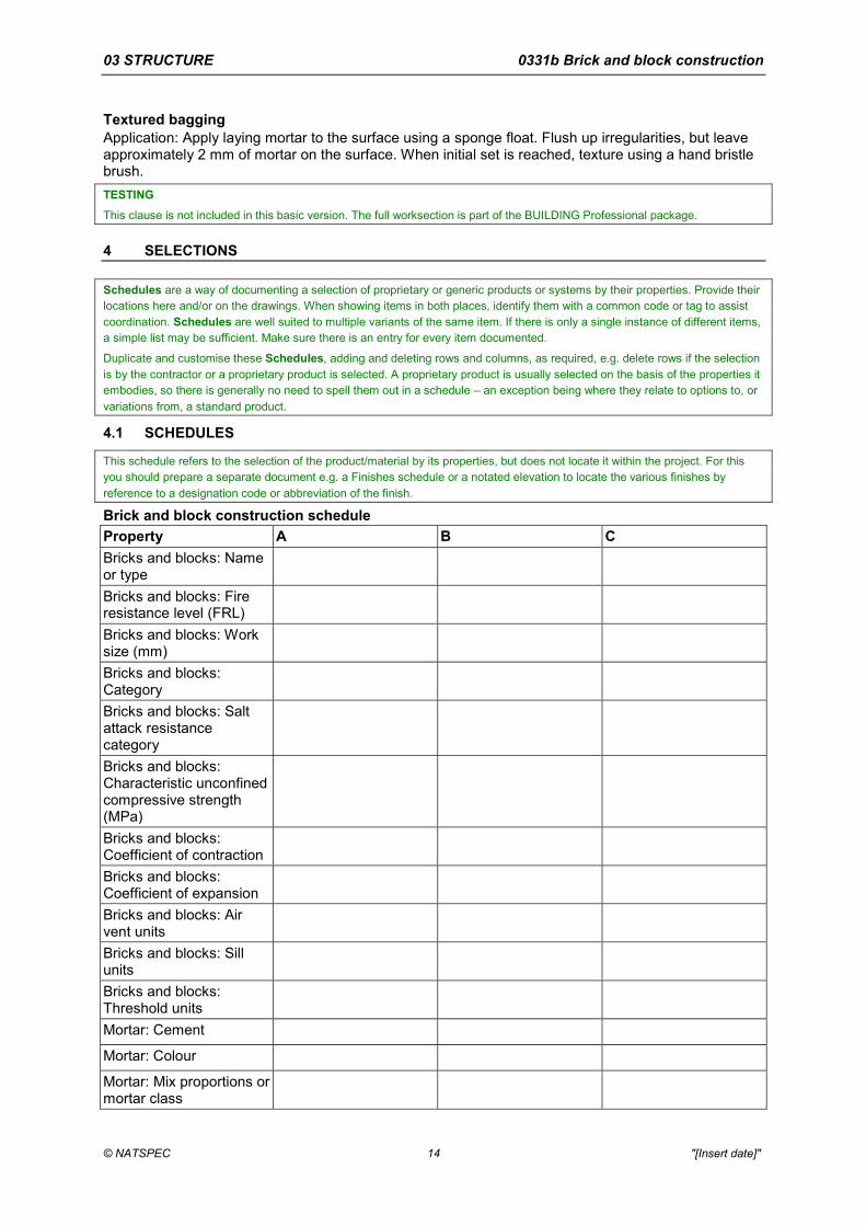
Schedules are a way of documenting a selection of proprietary or generic products or systems by their properties. Provide their locations here and/or on the drawings. When showing items in both places, identify them with a common code or tag to assist coordination. Schedules are well suited to multiple variants of the same item. If there is only a single instance of different items, a simple list may be sufficient. Make sure there is an entry for every item documented.
Duplicate and customise these Schedules, adding and deleting rows and columns, as required, e.g. delete rows if the selection is by the contractor or a proprietary product is selected. A proprietary product is usually selected on the basis of the properties it embodies, so there is generally no need to spell them out in a schedule – an exception being where they relate to options to, or variations from, a standard product.
4.1 SCHEDULES
This schedule refers to the selection of the product/material by its properties, but does not locate it within the project. For this you should prepare a separate document e.g. a Finishes schedule or a notated elevation to locate the various finishes by reference to a designation code or abbreviation of the finish.
Brick and block construction schedule Property A B C Bricks and blocks: Name or type
Bricks and blocks: Fire resistance level (FRL)
Bricks and blocks: Work size (mm)
Bricks and blocks: Category
Bricks and blocks: Salt attack resistance category
Bricks and blocks: Characteristic unconfined compressive strength (MPa)
Bricks and blocks: Coefficient of contraction
Bricks and blocks: Coefficient of expansion
Bricks and blocks: Air vent units
Bricks and blocks: Sill units
Bricks and blocks: Threshold units
Mortar: Cement
Mortar: Colour
Mortar: Mix proportions or mortar class
03 STRUCTURE 0331b Brick and block construction
© NATSPEC 15 "[Insert date]"
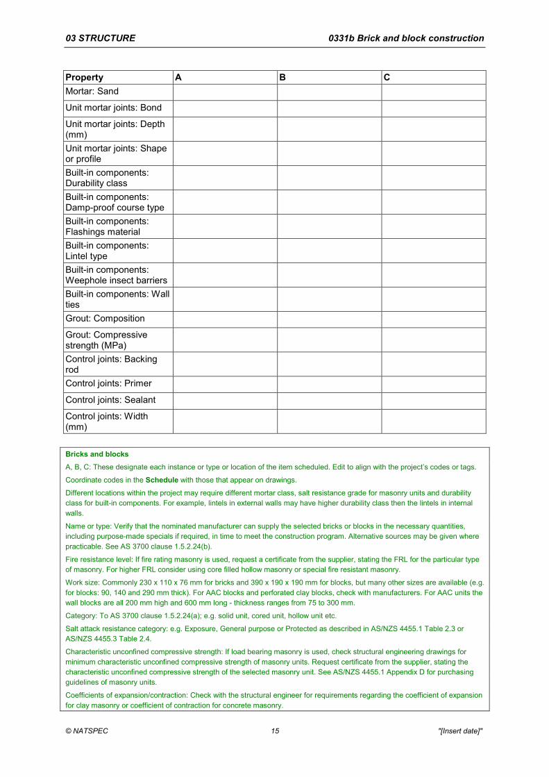
Property A B C Mortar: Sand
Unit mortar joints: Bond
Unit mortar joints: Depth (mm)
Unit mortar joints: Shape or profile
Built-in components: Durability class
Built-in components: Damp-proof course type
Built-in components: Flashings material
Built-in components: Lintel type
Built-in components: Weephole insect barriers
Built-in components: Wall ties
Grout: Composition
Grout: Compressive strength (MPa)
Control joints: Backing rod
Control joints: Primer
Control joints: Sealant
Control joints: Width (mm)
Bricks and blocks A, B, C: These designate each instance or type or location of the item scheduled. Edit to align with the project’s codes or tags.
Coordinate codes in the Schedule with those that appear on drawings.
Different locations within the project may require different mortar class, salt resistance grade for masonry units and durability class for built-in components. For example, lintels in external walls may have higher durability class then the lintels in internal walls.
Name or type: Verify that the nominated manufacturer can supply the selected bricks or blocks in the necessary quantities, including purpose-made specials if required, in time to meet the construction program. Alternative sources may be given where practicable. See AS 3700 clause 1.5.2.24(b).
Fire resistance level: If fire rating masonry is used, request a certificate from the supplier, stating the FRL for the particular type of masonry. For higher FRL consider using core filled hollow masonry or special fire resistant masonry.
Work size: Commonly 230 x 110 x 76 mm for bricks and 390 x 190 x 190 mm for blocks, but many other sizes are available (e.g. for blocks: 90, 140 and 290 mm thick). For AAC blocks and perforated clay blocks, check with manufacturers. For AAC units the wall blocks are all 200 mm high and 600 mm long - thickness ranges from 75 to 300 mm.
Category: To AS 3700 clause 1.5.2.24(a); e.g. solid unit, cored unit, hollow unit etc.
Salt attack resistance category: e.g. Exposure, General purpose or Protected as described in AS/NZS 4455.1 Table 2.3 or AS/NZS 4455.3 Table 2.4.
Characteristic unconfined compressive strength: If load bearing masonry is used, check structural engineering drawings for minimum characteristic unconfined compressive strength of masonry units. Request certificate from the supplier, stating the characteristic unconfined compressive strength of the selected masonry unit. See AS/NZS 4455.1 Appendix D for purchasing guidelines of masonry units.
Coefficients of expansion/contraction: Check with the structural engineer for requirements regarding the coefficient of expansion for clay masonry or coefficient of contraction for concrete masonry.

03 STRUCTURE 0331b Brick and block construction
© NATSPEC 16 "[Insert date]"
Mortar Cement: Nominate type.
Colour: Nominate pigment.
Sand: Nominate supplier where essential for the selected colour.
Unit mortar joints Unit mortar joints: e.g. Ironed with a 12 mm diameter rod, Cut and struck, Weatherstruck, Flush jointed, Raked out 5 mm deep and ironed square (or half round), Broomed, To match existing, or As shown on the drawings, etc. Raked joints are generally not recommended. The exposed mortar face should be compressed. Tuck pointing, if required, should be clearly documented.
Built-in components
Damp-proof course type: e.g. Bitumen coated and flashing material, metal, polyethylene, see AS/NZS 2904 clause 7.
Wall ties: Specify resilient wall ties if sound insulation is required.
For proprietary systems such as AAC blockwork, manufacturer’s recommendations and CSIRO Appraisal limitations, if any, should be applied. Repair of AAC blockwork, which is easily damaged in handling, requires careful documentation.
For building designs conforming to AS 4773, make sure all assigned properties do not contradict with the deemed-to-satisfy values in AS 4773.
Brick and block construction performance schedule for special masonry Property A B C Durability test
Compressive strength (MPa)
Flexural strength A, B, C: These designate each instance or type or location of the item scheduled. Edit to align with the project’s codes or tags.
Coordinate codes in the Schedule with those that appear on drawings.
Delete this schedule if there is no special masonry in the project.
Testing for strength of special masonry is mandatory in AS 3700. Deemed-to-satisfy masonry is normally not tested except where doubt exists whether the required properties are being achieved on site, see AS 3700 clause 12.6.
Lintel schedule Opening dimensions (mm)
Lintel type Depth1 (mm) Width (mm) Thickness (mm)
Note: Lintel length required is equal to sum of (opening dimension + 2x bearing at each end). 1Omit depth for flat steel lintels.
Lintel type: e.g. steel angle or product name.
Lintel types include steel, precast reinforced concrete or prestressed concrete and reinforced terracotta. Precast proprietary concrete lintels are also available and may be documented as an alternative to steel. Consult the structural engineer before using proprietary lintels with concrete or calcium silicate bricks, or clay bricks with more than 25% perforation. If proprietary lintels are required, nominate manufacturer. Heads of some steel door frames may be used as lintels. Consult manufacturer.
REFERENCED DOCUMENTS The following documents are incorporated into this worksection by reference: AS 1672 Limes and limestones AS 1672.1 1997 Limes for building AS/NZS 2699 Built-in components for masonry construction AS/NZS 2699.1 2000 Wall ties AS/NZS 2699.2 2000 Connectors and accessories AS/NZS 2699.3 2002 Lintels and shelf angles (durability requirements) AS/NZS 2904 1995 Damp-proof courses and flashings AS 3566 Self-drilling screws for the building and construction industries AS 3566.1 2002 General requirements and mechanical properties AS/NZS 3679 Structural steel AS/NZS 3679.1 2010 Hot-rolled bars and sections
03 STRUCTURE 0331b Brick and block construction
© NATSPEC 17 "[Insert date]"
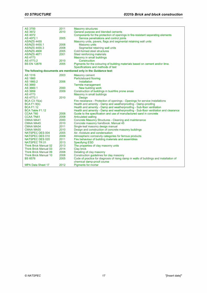
AS 3700 2011 Masonry structures AS 3972 2010 General purpose and blended cements AS 4072 Components for the protection of openings in fire-resistant separating elements AS 4072.1 2005 Service penetrations and control joints AS/NZS 4455 Masonry units, pavers, flags and segmental retaining wall units AS/NZS 4455.1 2008 Masonry units AS/NZS 4455.3 2008 Segmental retaining wall units AS/NZS 4600 2005 Cold-formed steel structures AS/NZS 4671 2001 Steel reinforcing materials AS 4773 Masonry in small buildings AS 4773.2 2010 Construction BS EN 12878 2005 Pigments for the colouring of building materials based on cement and/or lime.
Specifications and methods of test The following documents are mentioned only in the Guidance text: AS 1316 2003 Masonry cement AS 1860 Particleboard flooring AS 1860.2 2006 Installation AS 3660 Termite management AS 3660.1 2000 New building work AS 3959 2009 Construction of buildings in bushfire prone areas AS 4773 Masonry in small buildings AS 4773.1 2010 Design BCA C3.15(a) Fire resistance - Protection of openings - Openings for service installations BCA F1.9(b) Health and amenity - Damp and weatherproofing - Damp-proofing BCA F1.12 Health and amenity - Damp and weatherproofing - Sub-floor ventilation BCA Table F1.12 Health and amenity - Damp and weatherproofing - Sub-floor ventilation and clearance CCAA T60 2008 Guide to the specification and use of manufactured sand in concrete CCAA TN61 2008 Articulated walling CMAA MA41 2000 Concrete Masonry Structures - Cleaning and maintenance CMAA MA45 2010 Concrete masonry handbook. Manual 45 CMAA MA54 2011 Single-leaf masonry design manual CMAA MA55 2010 Design and construction of concrete masonry buildings NATSPEC DES 004 2005 Air, moisture and condensation NATSPEC DES 010 2009 Atmospheric corrosivity categories for ferrous products NATSPEC DES 020 2011 Fire behaviour of building materials and assemblies NATSPEC TR 01 2013 Specifying ESD Think Brick Manual 02 2013 The properties of clay masonry units Think Brick Manual 03 2014 Clay brick Think Brick Manual 09 2008 Detailing of clay masonry Think Brick Manual 10 2008 Construction guidelines for clay masonry BS 6576 2005 Code of practice for diagnosis of rising damp in walls of buildings and installation of
chemical damp-proof course MPA Data Sheet 17 2012 Pigments for mortar