Embed Size (px)
Citation preview
1/23/17
1
Issue Date:
Revision:
Deploy MPLS VPWS
[201609]
[01]
APNIC Technical Workshop January 23 to 25, 2017. NZNOG2017, Tauranga, New Zealand.
Acknowledgement
• Cisco Systems
2
1/23/17
2
3
MPLS L2 VPN
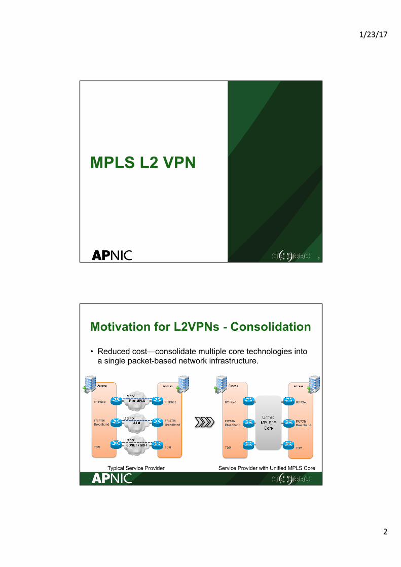
Motivation for L2VPNs - Consolidation
• Reduced cost—consolidate multiple core technologies into a single packet-based network infrastructure.
Typical Service Provider Service Provider with Unified MPLS Core
1/23/17
3
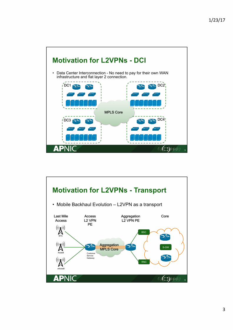
Motivation for L2VPNs - DCI• Data Center Interconnection - No need to pay for their own WAN infrastructure and flat layer 2 connection.
5
MPLS Core
DC1 DC2
DC4DC3
Motivation for L2VPNs - Transport
• Mobile Backhaul Evolution – L2VPN as a transport
6
Access L2 VPN PE
Aggregation L2 VPN PE
Core Last Mile Access
Aggregation MPLS Core
BTS
NodeB
eNodeB
CustomerServiceGateway
BSC
RNC
S-GW
1/23/17
4
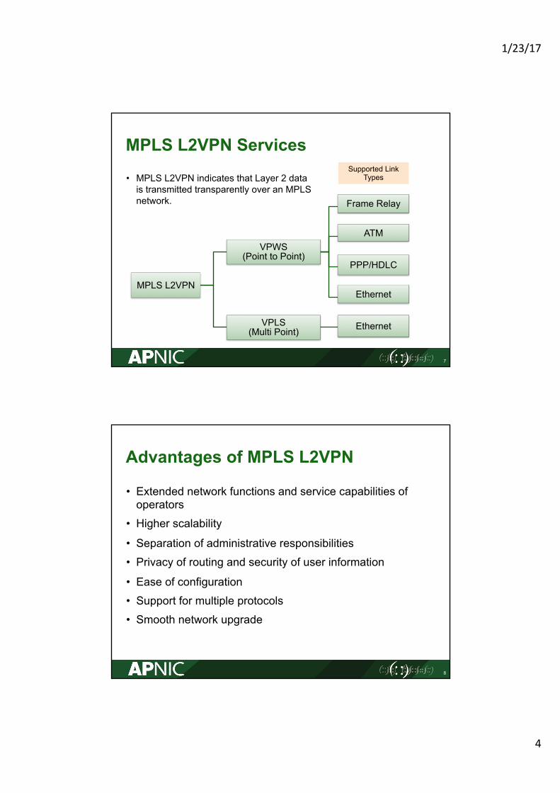
MPLS L2VPN Services
• MPLS L2VPN indicates that Layer 2 data is transmitted transparently over an MPLS network.
7
MPLS L2VPN
VPWS(Point to Point)
Frame Relay
ATM
PPP/HDLC
Ethernet
VPLS(Multi Point) Ethernet
Supported Link Types
Advantages of MPLS L2VPN
• Extended network functions and service capabilities of operators
• Higher scalability
• Separation of administrative responsibilities• Privacy of routing and security of user information
• Ease of configuration• Support for multiple protocols• Smooth network upgrade
8
1/23/17
5
9
VPWS Overview
VPWS Reference Model
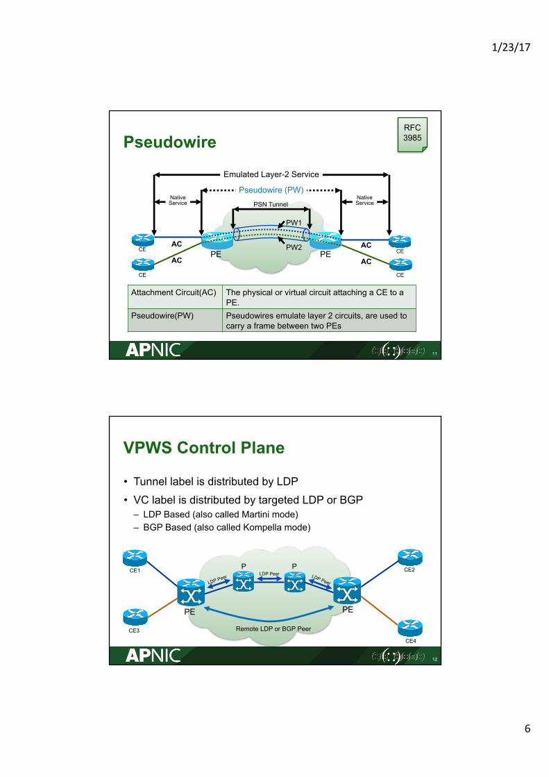
• VPWS emulates leased lines on an IP network to provide low-cost asymmetrical digital data network service.
10
CE
CE
CE
PE
PE PE
MPLS Core
Point-to-Point
ATM
EthernetFrameRelay
1/23/17
6
Pseudowire
11
Attachment Circuit(AC) The physical or virtual circuit attaching a CE to a PE.
Pseudowire(PW) Pseudowires emulate layer 2 circuits, are used to carry a frame between two PEs
Emulated Layer-2 Service
Pseudowire (PW)PSN Tunnel
PEPE
CE
CE
CE
CEPW2
PW1
NativeService
NativeService
AC
AC
AC
AC
RFC3985
VPWS Control Plane
• Tunnel label is distributed by LDP• VC label is distributed by targeted LDP or BGP– LDP Based (also called Martini mode)– BGP Based (also called Kompella mode)
12
PEPE
CE3
CE1
CE4
CE2P P
Remote LDP or BGP Peer
1/23/17
7
Data Plane of VPWS
13
PEPE
CE3
CE1
CE4
CE2P P
L2 Payload
45 100 L2 Payload
50 100 L2 Payload
100 L2 Payload
L2 Payload
L2 Payload
45 200 L2 Payload
50 200 L2 PayloadL2 Payload
200 L2 Payload
Length Sequence Number0 0 0 0 Flags
EXP TTL (Set to 2)1VC Label (VC)
EXP TTL0Tunnel Label (LDP)
Layer 2 PDU
FRG
VC Label
Tunnel Label
Control Word
VPWS Traffic Encapsulation
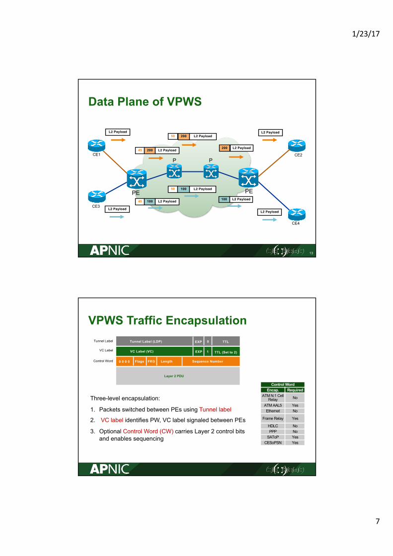
Three-level encapsulation:
1. Packets switched between PEs using Tunnel label
2. VC label identifies PW, VC label signaled between PEs
3. Optional Control Word (CW) carries Layer 2 control bits and enables sequencing
Control WordEncap. Required
ATM N:1 Cell Relay No
ATM AAL5 YesEthernet No
Frame Relay Yes
HDLC NoPPP NoSAToP YesCESoPSN Yes
1/23/17
8
VPWS Service Like-to-Like Transport
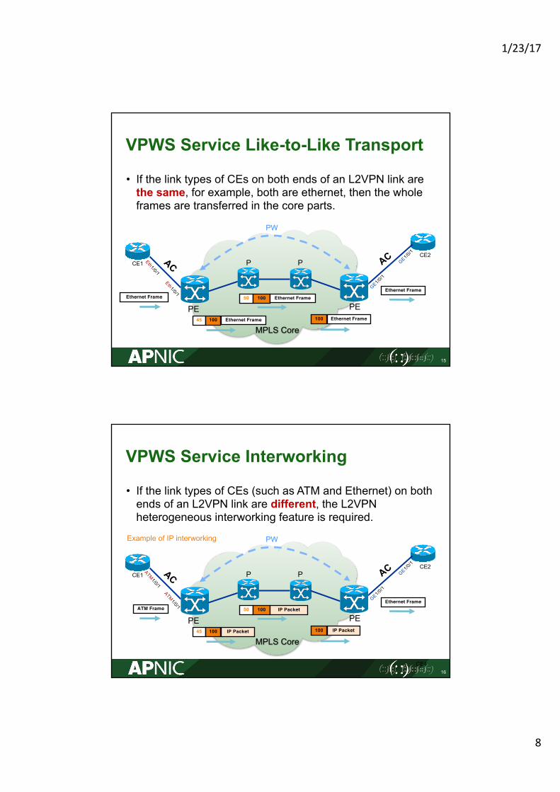
• If the link types of CEs on both ends of an L2VPN link are the same, for example, both are ethernet, then the whole frames are transferred in the core parts.
15
PEPE
CE1CE2
P P
PW
Ethernet Frame
45 100 Ethernet Frame
50 100 Ethernet Frame
100 Ethernet Frame
Ethernet Frame
MPLS Core
VPWS Service Interworking
• If the link types of CEs (such as ATM and Ethernet) on both ends of an L2VPN link are different, the L2VPN heterogeneous interworking feature is required.
16
PEPE
CE1
CE4
CE2P P
PW
ATM Frame
45 100 IP Packet
50 100 IP Packet
100 IP Packet
Ethernet Frame
Example of IP interworking
MPLS Core
1/23/17
9
Raw Mode & Tagged Mode
• Ethernet PW has two modes of operation:– Ethernet VLAN / Tagged mode (VC type 0x0004) – Each frame must contain a VLAN tag. The tag value is meaningful to both the ingress and egress PE routers.
– Ethernet Port / Raw mode (VC type 0x0005) – In raw mode, an Ethernet frame might or might not have a VLAN tag. If the frame does have this tag, the tag is not meaningful to both the ingress and egress PE routers.
17
RFC4448
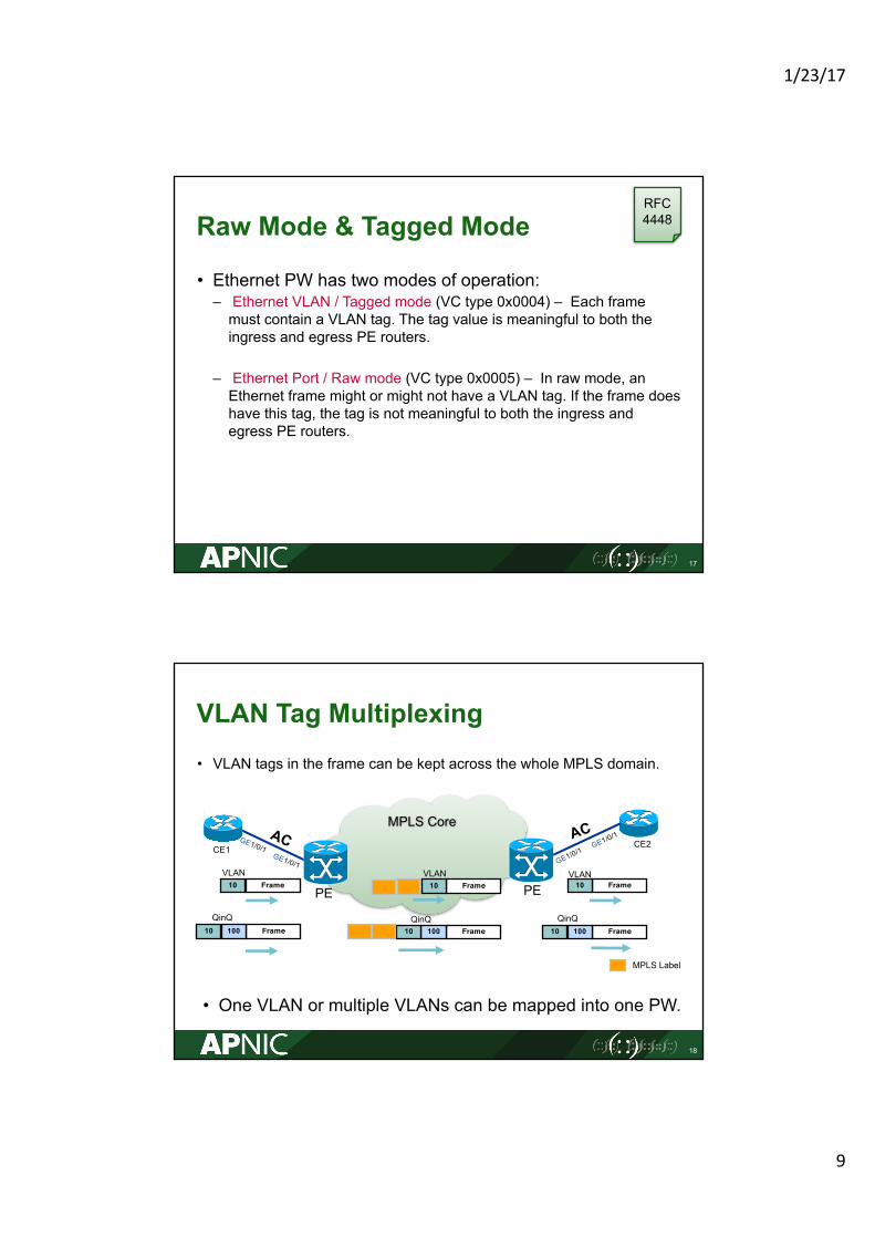
VLAN Tag Multiplexing• VLAN tags in the frame can be kept across the whole MPLS domain.
18
PEPE
CE1 CE2
MPLS Core
MPLS Label
• One VLAN or multiple VLANs can be mapped into one PW.
Frame10010QinQ
Frame10010QinQ
Frame10010QinQ
VLANFrame10 Frame10
VLANFrame10
VLAN
1/23/17
10
VLAN Tag Translation and Manipulation
• VLAN tags can be added, removed or translated prior to VC label imposition or after disposition– Any VLAN tag(s), if retained, will appear as payload to the VC
19
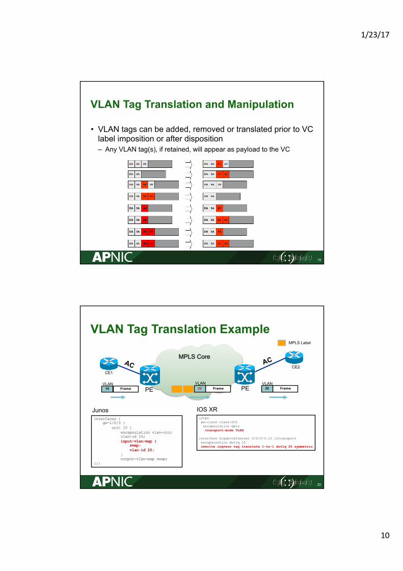
VLAN Tag Translation Example
20
PEPE
CE1CE2
MPLS Core
MPLS Label
l2vpnpw-class class-VC5encapsulation mplstransport-mode VLAN
interface GigabitEthernet 0/0/0/3.10 l2transportencapsulation dot1q 10rewrite ingress tag translate 1-to-1 dot1q 20 symmetric
interfaces {ge-1/0/3 {
unit 10 {encapsulation vlan-ccc;vlan-id 10;input-vlan-map {
swap;vlan-id 20;
}output-vlan-map swap;
}}}
IOS XRJunos
Frame20VLAN
Frame10VLAN
Frame20VLAN
1/23/17
11
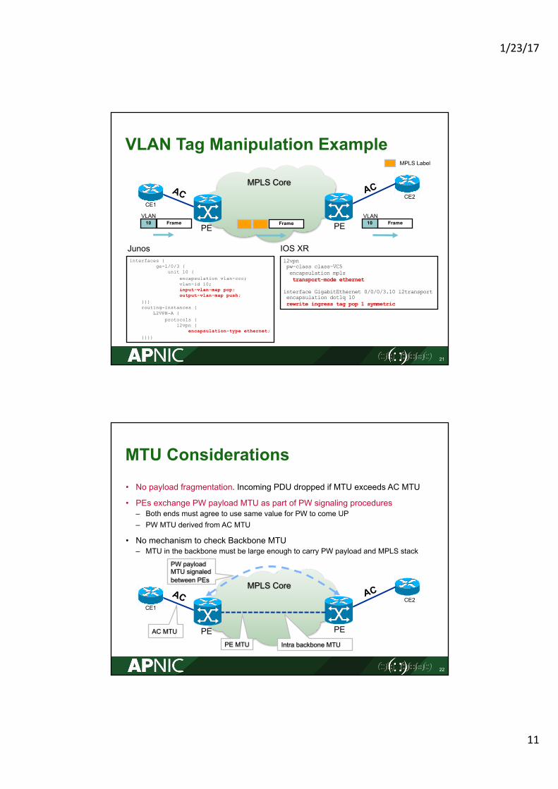
VLAN Tag Manipulation Example
21
PEPE
CE1CE2
MPLS Core
MPLS Label
Frame
l2vpnpw-class class-VC5encapsulation mplstransport-mode ethernet
interface GigabitEthernet 0/0/0/3.10 l2transportencapsulation dot1q 10rewrite ingress tag pop 1 symmetric
interfaces {ge-1/0/3 {
unit 10 {encapsulation vlan-ccc;vlan-id 10;input-vlan-map pop;output-vlan-map push;
}}}routing-instances {
L2VPN-A {protocols {
l2vpn {encapsulation-type ethernet;
}}}}
IOS XRJunos
Frame10VLAN
Frame10VLAN
MTU Considerations• No payload fragmentation. Incoming PDU dropped if MTU exceeds AC MTU
• PEs exchange PW payload MTU as part of PW signaling procedures– Both ends must agree to use same value for PW to come UP– PW MTU derived from AC MTU
• No mechanism to check Backbone MTU– MTU in the backbone must be large enough to carry PW payload and MPLS stack
22
PEPE
CE1CE2
MPLS Core
PW payload MTU signaled between PEs
AC MTU
PE MTU Intra backbone MTU
1/23/17
12
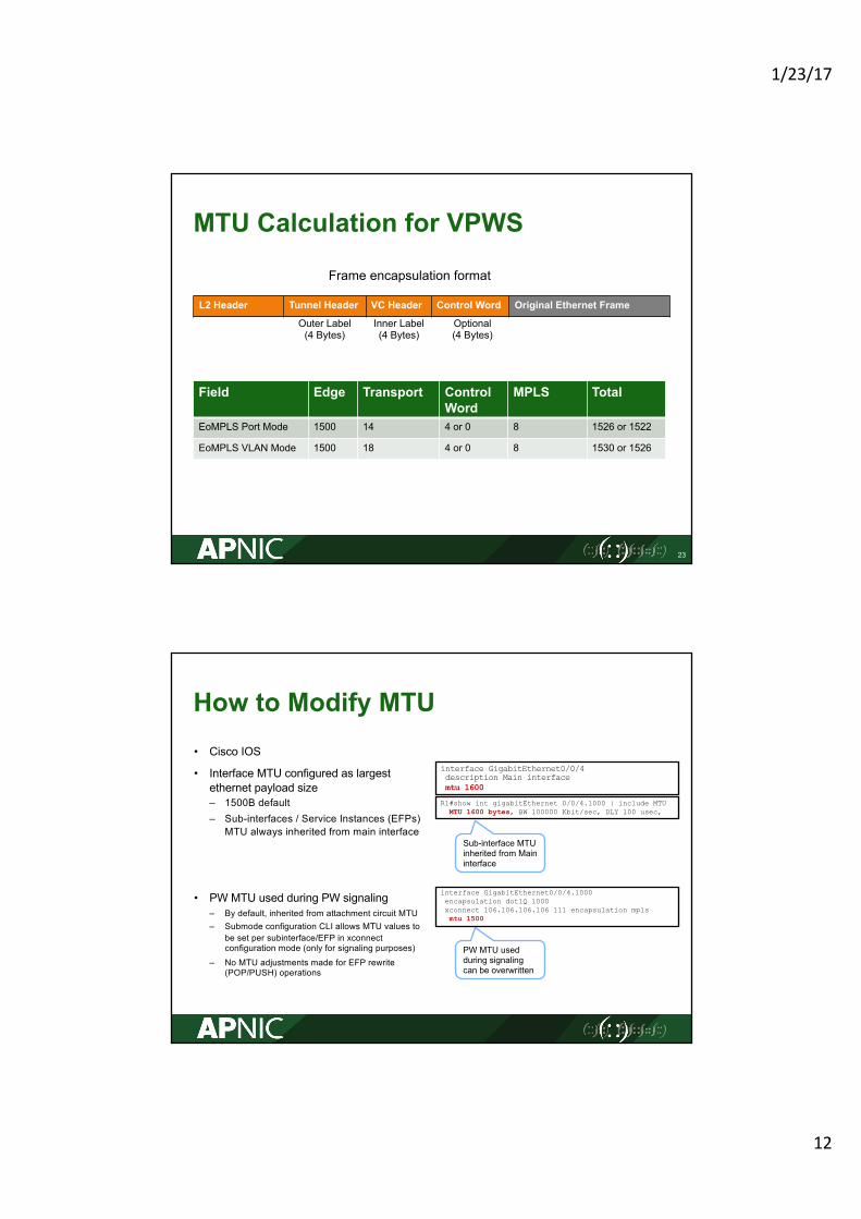
MTU Calculation for VPWS
L2 Header Tunnel Header VC Header Control Word Original Ethernet Frame
23
Outer Label(4 Bytes)
Inner Label(4 Bytes)
Optional(4 Bytes)
Frame encapsulation format
Field Edge Transport Control Word
MPLS Total
EoMPLS Port Mode 1500 14 4 or 0 8 1526 or 1522
EoMPLS VLAN Mode 1500 18 4 or 0 8 1530 or 1526
How to Modify MTU• Cisco IOS
• Interface MTU configured as largest ethernet payload size– 1500B default– Sub-interfaces / Service Instances (EFPs)
MTU always inherited from main interface
• PW MTU used during PW signaling– By default, inherited from attachment circuit MTU– Submode configuration CLI allows MTU values to
be set per subinterface/EFP in xconnectconfiguration mode (only for signaling purposes)
– No MTU adjustments made for EFP rewrite (POP/PUSH) operations
interface GigabitEthernet0/0/4description Main interfacemtu 1600
R1#show int gigabitEthernet 0/0/4.1000 | include MTUMTU 1600 bytes, BW 100000 Kbit/sec, DLY 100 usec,
Sub-interface MTU inherited from Main interface
PW MTU used during signaling can be overwritten
interface GigabitEthernet0/0/4.1000encapsulation dot1Q 1000xconnect 106.106.106.106 111 encapsulation mplsmtu 1500
1/23/17
13
25
VPWS Signaled with LDP
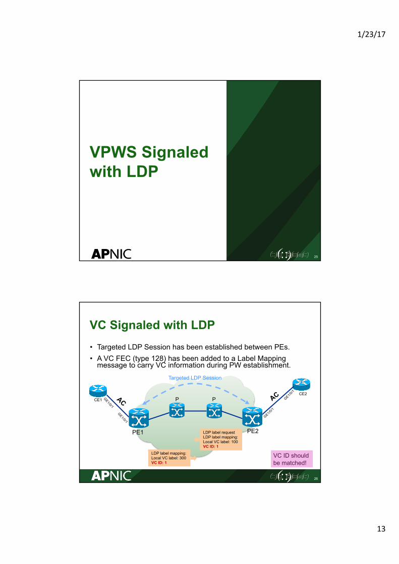
VC Signaled with LDP• Targeted LDP Session has been established between PEs.• A VC FEC (type 128) has been added to a Label Mapping message to carry VC information during PW establishment.
26
PE2PE1
CE1CE2
P P
Targeted LDP Session
LDP label mapping:Local VC label: 300VC ID: 1
LDP label requestLDP label mapping:Local VC label: 100VC ID: 1
VC ID should be matched!
1/23/17
14
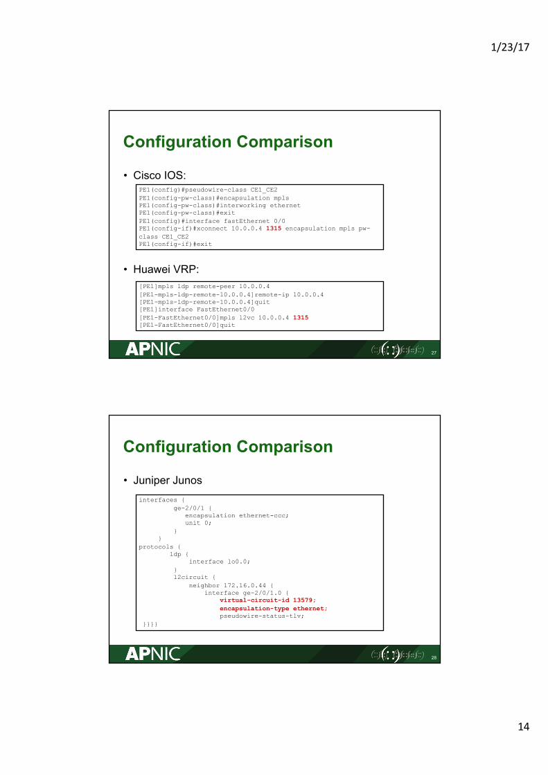
Configuration Comparison
• Cisco IOS:
• Huawei VRP:
27
PE1(config)#pseudowire-class CE1_CE2PE1(config-pw-class)#encapsulation mplsPE1(config-pw-class)#interworking ethernetPE1(config-pw-class)#exitPE1(config)#interface fastEthernet 0/0PE1(config-if)#xconnect 10.0.0.4 1315 encapsulation mpls pw-class CE1_CE2PE1(config-if)#exit
[PE1]mpls ldp remote-peer 10.0.0.4[PE1-mpls-ldp-remote-10.0.0.4]remote-ip 10.0.0.4[PE1-mpls-ldp-remote-10.0.0.4]quit[PE1]interface FastEthernet0/0[PE1-FastEthernet0/0]mpls l2vc 10.0.0.4 1315[PE1-FastEthernet0/0]quit
Configuration Comparison
• Juniper Junos
28
interfaces {ge-2/0/1 {
encapsulation ethernet-ccc;unit 0;
}}
protocols {ldp {
interface lo0.0;}l2circuit {
neighbor 172.16.0.44 {interface ge-2/0/1.0 {
virtual-circuit-id 13579;encapsulation-type ethernet;pseudowire-status-tlv;
}}}}
1/23/17
15
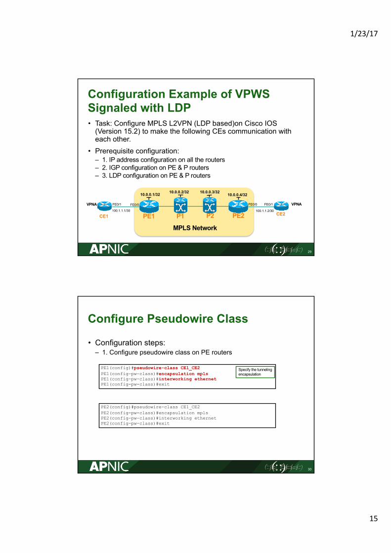
Configuration Example of VPWS Signaled with LDP • Task: Configure MPLS L2VPN (LDP based)on Cisco IOS (Version 15.2) to make the following CEs communication with each other.
• Prerequisite configuration:– 1. IP address configuration on all the routers– 2. IGP configuration on PE & P routers– 3. LDP configuration on PE & P routers
29
PE1
MPLS Network
PE2P1 P2CE1 CE2
VPNA VPNA100.1.1.1/30
10.0.0.1/32 10.0.0.2/32 10.0.0.3/32 10.0.0.4/32
FE0/1 FE0/1
100.1.1.2/30
FE0/0 FE0/0
Configure Pseudowire Class
• Configuration steps:– 1. Configure pseudowire class on PE routers
30
PE1(config)#pseudowire-class CE1_CE2PE1(config-pw-class)#encapsulation mplsPE1(config-pw-class)#interworking ethernetPE1(config-pw-class)#exit
PE2(config)#pseudowire-class CE1_CE2PE2(config-pw-class)#encapsulation mplsPE2(config-pw-class)#interworking ethernetPE2(config-pw-class)#exit
Specify the tunneling encapsulation
1/23/17
16
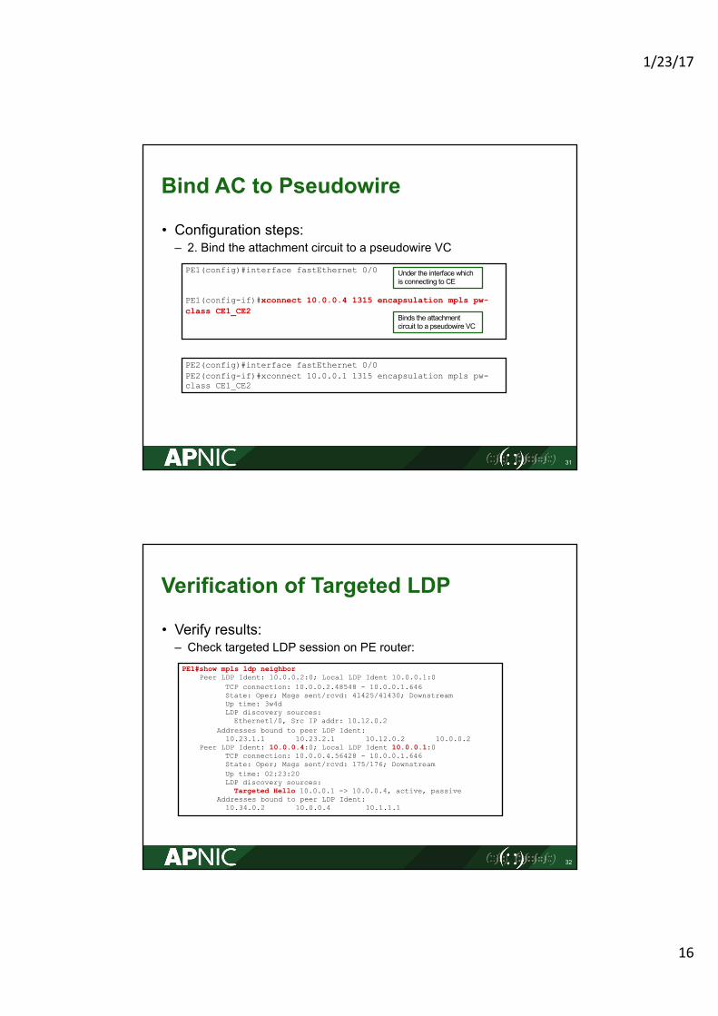
Bind AC to Pseudowire
• Configuration steps:– 2. Bind the attachment circuit to a pseudowire VC
31
PE1(config)#interface fastEthernet 0/0
PE1(config-if)#xconnect 10.0.0.4 1315 encapsulation mpls pw-class CE1_CE2
PE2(config)#interface fastEthernet 0/0PE2(config-if)#xconnect 10.0.0.1 1315 encapsulation mpls pw-class CE1_CE2
Binds the attachment circuit to a pseudowire VC
Under the interface which is connecting to CE
Verification of Targeted LDP
• Verify results:– Check targeted LDP session on PE router:
32
PE1#show mpls ldp neighborPeer LDP Ident: 10.0.0.2:0; Local LDP Ident 10.0.0.1:0
TCP connection: 10.0.0.2.48548 - 10.0.0.1.646State: Oper; Msgs sent/rcvd: 41425/41430; DownstreamUp time: 3w4dLDP discovery sources:
Ethernet1/0, Src IP addr: 10.12.0.2Addresses bound to peer LDP Ident:
10.23.1.1 10.23.2.1 10.12.0.2 10.0.0.2Peer LDP Ident: 10.0.0.4:0; Local LDP Ident 10.0.0.1:0
TCP connection: 10.0.0.4.56428 - 10.0.0.1.646State: Oper; Msgs sent/rcvd: 175/176; DownstreamUp time: 02:23:20LDP discovery sources:
Targeted Hello 10.0.0.1 -> 10.0.0.4, active, passiveAddresses bound to peer LDP Ident:
10.34.0.2 10.0.0.4 10.1.1.1
1/23/17
17
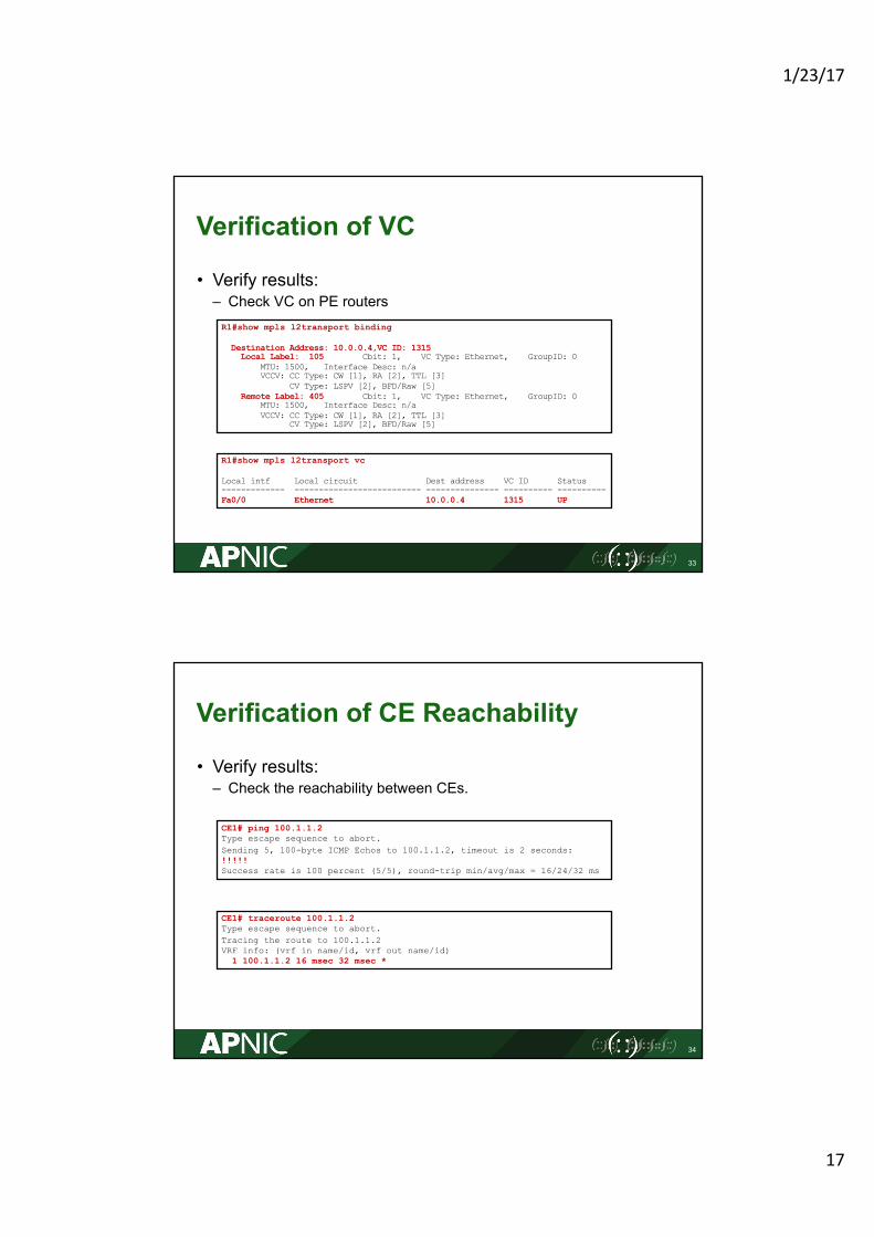
Verification of VC
• Verify results:– Check VC on PE routers
33
R1#show mpls l2transport binding
Destination Address: 10.0.0.4,VC ID: 1315Local Label: 105 Cbit: 1, VC Type: Ethernet, GroupID: 0
MTU: 1500, Interface Desc: n/aVCCV: CC Type: CW [1], RA [2], TTL [3]
CV Type: LSPV [2], BFD/Raw [5]Remote Label: 405 Cbit: 1, VC Type: Ethernet, GroupID: 0
MTU: 1500, Interface Desc: n/aVCCV: CC Type: CW [1], RA [2], TTL [3]
CV Type: LSPV [2], BFD/Raw [5]
R1#show mpls l2transport vc
Local intf Local circuit Dest address VC ID Status------------- -------------------------- --------------- ---------- ----------Fa0/0 Ethernet 10.0.0.4 1315 UP
Verification of CE Reachability
• Verify results:– Check the reachability between CEs.
34
CE1# ping 100.1.1.2Type escape sequence to abort.Sending 5, 100-byte ICMP Echos to 100.1.1.2, timeout is 2 seconds:!!!!!Success rate is 100 percent (5/5), round-trip min/avg/max = 16/24/32 ms
CE1# traceroute 100.1.1.2Type escape sequence to abort.Tracing the route to 100.1.1.2VRF info: (vrf in name/id, vrf out name/id)
1 100.1.1.2 16 msec 32 msec *
1/23/17
18
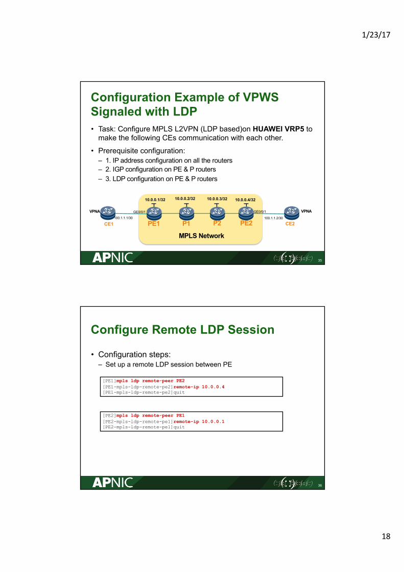
Configuration Example of VPWS Signaled with LDP • Task: Configure MPLS L2VPN (LDP based)on HUAWEI VRP5 to make the following CEs communication with each other.
• Prerequisite configuration:– 1. IP address configuration on all the routers– 2. IGP configuration on PE & P routers– 3. LDP configuration on PE & P routers
35
PE1
MPLS Network
PE2P1 P2CE1 CE2
VPNA VPNA100.1.1.1/30
10.0.0.1/32 10.0.0.2/32 10.0.0.3/32 10.0.0.4/32
100.1.1.2/30
GE0/0/1 GE0/0/1
Configure Remote LDP Session
• Configuration steps:– Set up a remote LDP session between PE
36
[PE1]mpls ldp remote-peer PE2[PE1-mpls-ldp-remote-pe2]remote-ip 10.0.0.4[PE1-mpls-ldp-remote-pe2]quit
[PE2]mpls ldp remote-peer PE1[PE2-mpls-ldp-remote-pe1]remote-ip 10.0.0.1[PE2-mpls-ldp-remote-pe1]quit
1/23/17
19
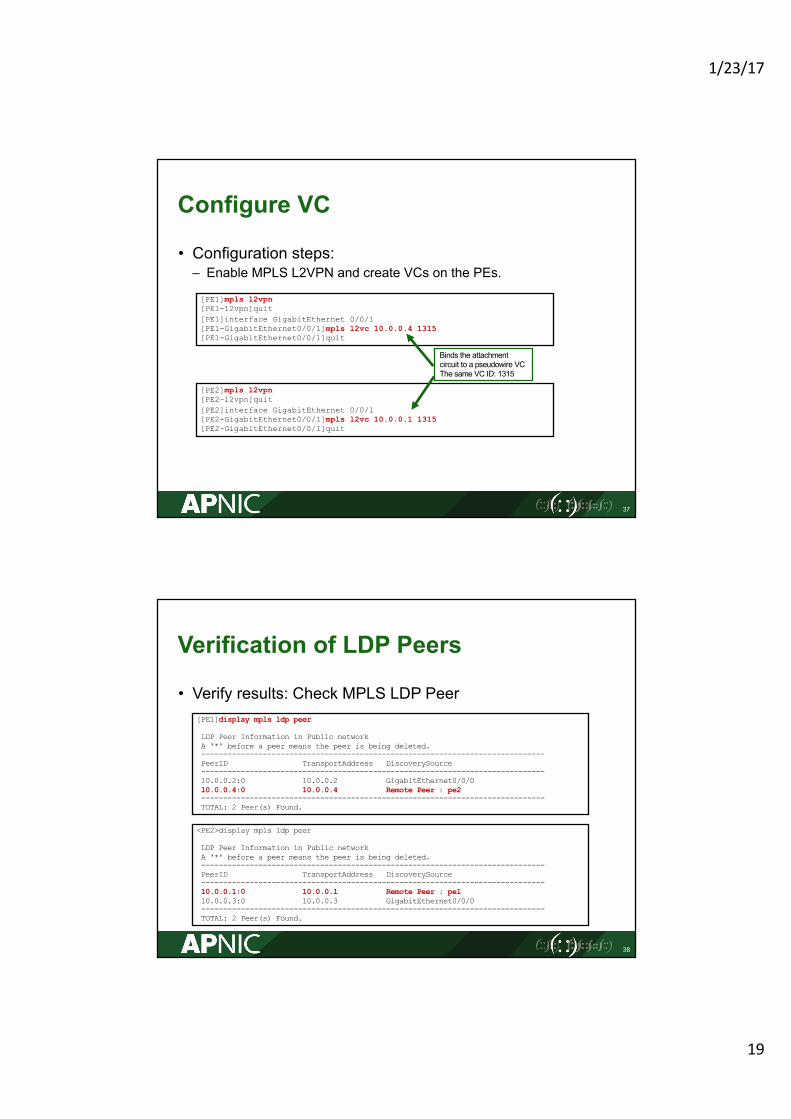
Configure VC
• Configuration steps:– Enable MPLS L2VPN and create VCs on the PEs.
37
[PE1]mpls l2vpn[PE1-l2vpn]quit[PE1]interface GigabitEthernet 0/0/1[PE1-GigabitEthernet0/0/1]mpls l2vc 10.0.0.4 1315[PE1-GigabitEthernet0/0/1]quit
[PE2]mpls l2vpn[PE2-l2vpn]quit[PE2]interface GigabitEthernet 0/0/1[PE2-GigabitEthernet0/0/1]mpls l2vc 10.0.0.1 1315[PE2-GigabitEthernet0/0/1]quit
Binds the attachment circuit to a pseudowire VCThe same VC ID: 1315
Verification of LDP Peers
• Verify results: Check MPLS LDP Peer
38
[PE1]display mpls ldp peer
LDP Peer Information in Public networkA '*' before a peer means the peer is being deleted.------------------------------------------------------------------------------PeerID TransportAddress DiscoverySource------------------------------------------------------------------------------10.0.0.2:0 10.0.0.2 GigabitEthernet0/0/010.0.0.4:0 10.0.0.4 Remote Peer : pe2------------------------------------------------------------------------------TOTAL: 2 Peer(s) Found.
<PE2>display mpls ldp peer
LDP Peer Information in Public networkA '*' before a peer means the peer is being deleted.------------------------------------------------------------------------------PeerID TransportAddress DiscoverySource------------------------------------------------------------------------------10.0.0.1:0 10.0.0.1 Remote Peer : pe110.0.0.3:0 10.0.0.3 GigabitEthernet0/0/0------------------------------------------------------------------------------TOTAL: 2 Peer(s) Found.
1/23/17
20
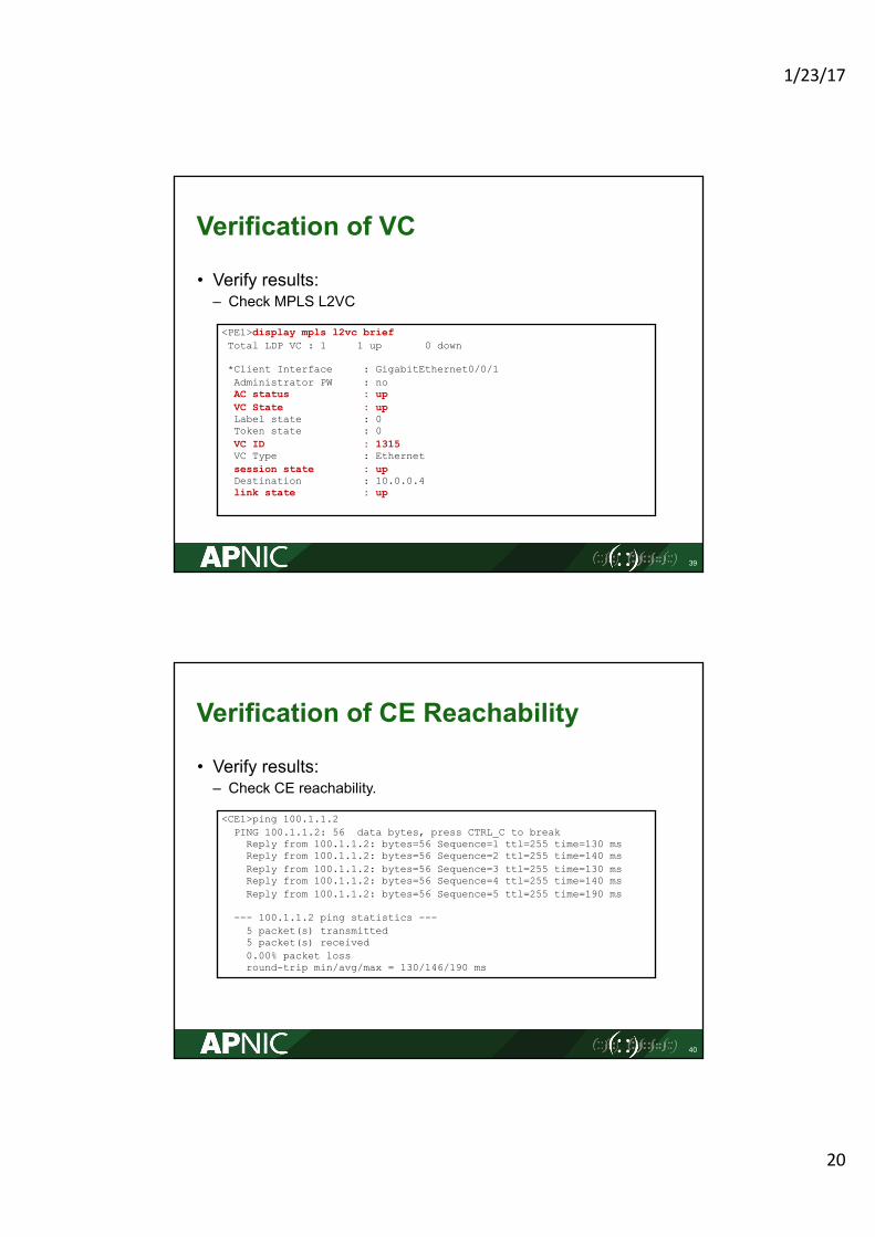
Verification of VC
• Verify results: – Check MPLS L2VC
39
<PE1>display mpls l2vc briefTotal LDP VC : 1 1 up 0 down
*Client Interface : GigabitEthernet0/0/1Administrator PW : noAC status : upVC State : upLabel state : 0Token state : 0VC ID : 1315VC Type : Ethernetsession state : upDestination : 10.0.0.4link state : up
Verification of CE Reachability
• Verify results: – Check CE reachability.
40
<CE1>ping 100.1.1.2PING 100.1.1.2: 56 data bytes, press CTRL_C to breakReply from 100.1.1.2: bytes=56 Sequence=1 ttl=255 time=130 msReply from 100.1.1.2: bytes=56 Sequence=2 ttl=255 time=140 msReply from 100.1.1.2: bytes=56 Sequence=3 ttl=255 time=130 msReply from 100.1.1.2: bytes=56 Sequence=4 ttl=255 time=140 msReply from 100.1.1.2: bytes=56 Sequence=5 ttl=255 time=190 ms
--- 100.1.1.2 ping statistics ---5 packet(s) transmitted5 packet(s) received0.00% packet lossround-trip min/avg/max = 130/146/190 ms
1/23/17
21
41
VPWS Signaled with BGP
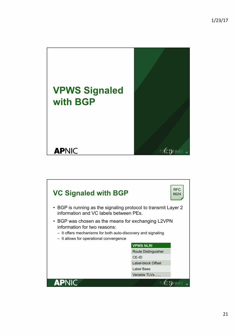
VC Signaled with BGP
• BGP is running as the signaling protocol to transmit Layer 2 information and VC labels between PEs.
• BGP was chosen as the means for exchanging L2VPN information for two reasons: – It offers mechanisms for both auto-discovery and signaling– It allows for operational convergence
42
RFC6624
VPWS NLRIRoute DistinguisherCE-IDLabel-block OffsetLabel BaseVariable TLVs…...
1/23/17
22
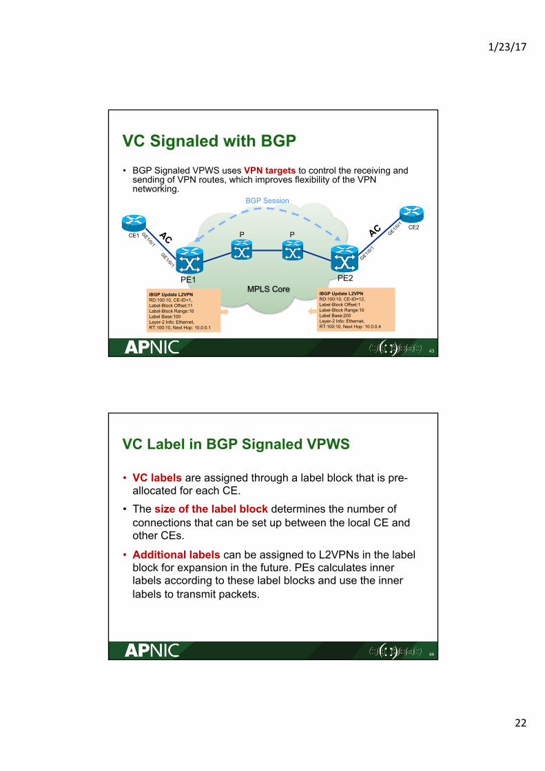
VC Signaled with BGP• BGP Signaled VPWS uses VPN targets to control the receiving and sending of VPN routes, which improves flexibility of the VPN networking.
43
PE2PE1
CE1CE2
P P
BGP Session
iBGP Update L2VPN RD:100:10, CE-ID=1, Label-Block Offset:11Label-Block Range:10Label Base:100Layer-2 Info: Ethernet,RT:100:10, Next Hop: 10.0.0.1
iBGP Update L2VPN RD:100:10, CE-ID=12, Label-Block Offset:1Label-Block Range:10Label Base:200Layer-2 Info: Ethernet,RT:100:10, Next Hop: 10.0.0.4
MPLS Core
VC Label in BGP Signaled VPWS
• VC labels are assigned through a label block that is pre-allocated for each CE.
• The size of the label block determines the number of connections that can be set up between the local CE and other CEs.
• Additional labels can be assigned to L2VPNs in the label block for expansion in the future. PEs calculates inner labels according to these label blocks and use the inner labels to transmit packets.
44
1/23/17
23
Basic Concepts
45
Concepts Explanation
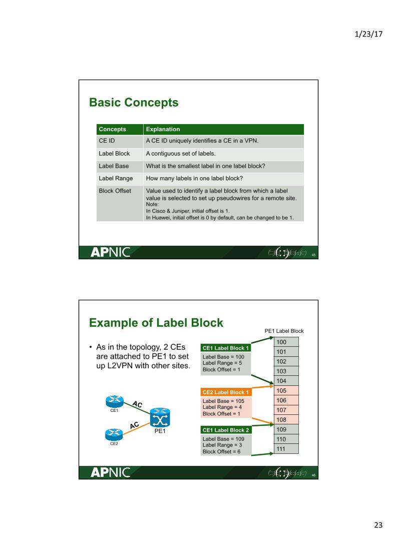
CE ID A CE ID uniquely identifies a CE in a VPN.
Label Block A contiguous set of labels.
Label Base What is the smallest label in one label block?
Label Range How many labels in one label block?
Block Offset Value used to identify a label block from which a label value is selected to set up pseudowires for a remote site.Note:In Cisco & Juniper, initial offset is 1.In Huawei, initial offset is 0 by default, can be changed to be 1.
Example of Label Block
• As in the topology, 2 CEs are attached to PE1 to set up L2VPN with other sites.
46
100101102103104105106107108109110111
PE1 Label Block
CE1 Label Block 1Label Base = 100Label Range = 5Block Offset = 1
CE2 Label Block 1Label Base = 105Label Range = 4Block Offset = 1
CE1 Label Block 2Label Base = 109Label Range = 3Block Offset = 6
PE1
CE1
CE2
1/23/17
24
VC Label Calculation
47
PE2PE1
CE1 CE3
BGP SessionLB=100LR=10LO=1
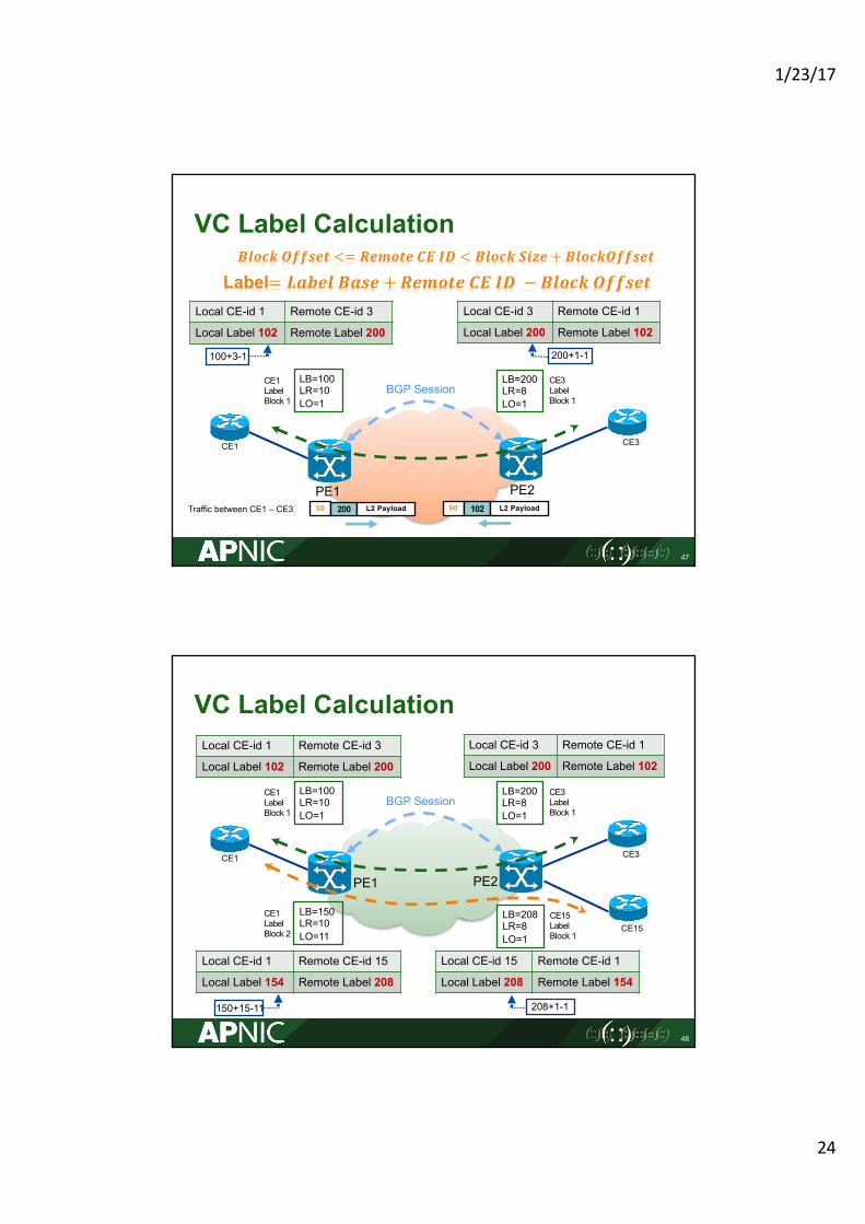
Local CE-id 1 Remote CE-id 3
Local Label 102 Remote Label 200
Local CE-id 3 Remote CE-id 1
Local Label 200 Remote Label 102
LB=200LR=8LO=1
100+3-1 200+1-1
CE1 Label Block 1
CE3 Label Block 1
Label= 𝑳𝒂𝒃𝒆𝒍 𝑩𝒂𝒔𝒆 + 𝑹𝒆𝒎𝒐𝒕𝒆 𝑪𝑬 𝑰𝑫 − 𝑩𝒍𝒐𝒄𝒌 𝑶𝒇𝒇𝒔𝒆𝒕
50 200 L2 Payload 60 102 L2 PayloadTraffic between CE1 – CE3
𝑩𝒍𝒐𝒄𝒌 𝑶𝒇𝒇𝒔𝒆𝒕 <= 𝑹𝒆𝒎𝒐𝒕𝒆 𝑪𝑬 𝑰𝑫 < 𝑩𝒍𝒐𝒄𝒌 𝑺𝒊𝒛𝒆 + 𝑩𝒍𝒐𝒄𝒌𝑶𝒇𝒇𝒔𝒆𝒕
VC Label Calculation
48
PE2PE1
CE1 CE3
Local CE-id 1 Remote CE-id 3
Local Label 102 Remote Label 200
Local CE-id 3 Remote CE-id 1
Local Label 200 Remote Label 102
CE15
BGP SessionLB=100LR=10LO=1
LB=200LR=8LO=1
CE1 Label Block 1
CE3 Label Block 1
LB=150LR=10LO=11
CE1 Label Block 2
Local CE-id 1 Remote CE-id 15
Local Label 154 Remote Label 208
150+15-11
LB=208LR=8LO=1
CE15 Label Block 1
Local CE-id 15 Remote CE-id 1
Local Label 208 Remote Label 154
208+1-1
1/23/17
25
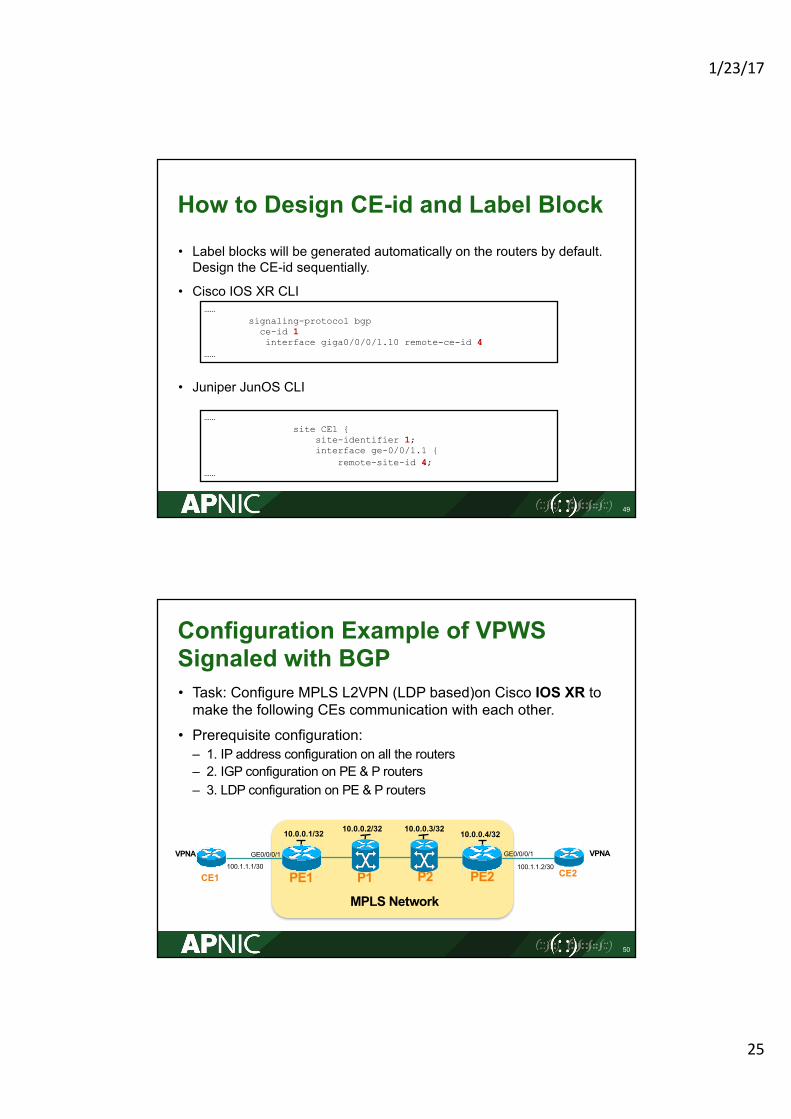
How to Design CE-id and Label Block
• Label blocks will be generated automatically on the routers by default. Design the CE-id sequentially.
• Cisco IOS XR CLI
• Juniper JunOS CLI
49
……signaling-protocol bgpce-id 1interface giga0/0/0/1.10 remote-ce-id 4
……
……site CE1 {
site-identifier 1;interface ge-0/0/1.1 {
remote-site-id 4;……
Configuration Example of VPWS Signaled with BGP • Task: Configure MPLS L2VPN (LDP based)on Cisco IOS XR to make the following CEs communication with each other.
• Prerequisite configuration:– 1. IP address configuration on all the routers– 2. IGP configuration on PE & P routers– 3. LDP configuration on PE & P routers
50
PE1
MPLS Network
PE2P1 P2CE1 CE2
VPNA VPNA100.1.1.1/30
10.0.0.1/32 10.0.0.2/32 10.0.0.3/32 10.0.0.4/32
100.1.1.2/30
GE0/0/0/1 GE0/0/0/1
1/23/17
26
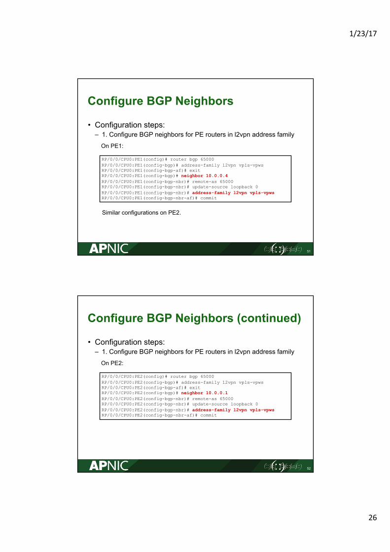
Configure BGP Neighbors
• Configuration steps:– 1. Configure BGP neighbors for PE routers in l2vpn address family
51
RP/0/0/CPU0:PE1(config)# router bgp 65000RP/0/0/CPU0:PE1(config-bgp)# address-family l2vpn vpls-vpwsRP/0/0/CPU0:PE1(config-bgp-af)# exit RP/0/0/CPU0:PE1(config-bgp)# neighbor 10.0.0.4RP/0/0/CPU0:PE1(config-bgp-nbr)# remote-as 65000RP/0/0/CPU0:PE1(config-bgp-nbr)# update-source loopback 0RP/0/0/CPU0:PE1(config-bgp-nbr)# address-family l2vpn vpls-vpwsRP/0/0/CPU0:PE1(config-bgp-nbr-af)# commit
On PE1:
Similar configurations on PE2.
Configure BGP Neighbors (continued)
• Configuration steps:– 1. Configure BGP neighbors for PE routers in l2vpn address family
52
RP/0/0/CPU0:PE2(config)# router bgp 65000RP/0/0/CPU0:PE2(config-bgp)# address-family l2vpn vpls-vpwsRP/0/0/CPU0:PE2(config-bgp-af)# exit RP/0/0/CPU0:PE2(config-bgp)# neighbor 10.0.0.1RP/0/0/CPU0:PE2(config-bgp-nbr)# remote-as 65000RP/0/0/CPU0:PE2(config-bgp-nbr)# update-source loopback 0RP/0/0/CPU0:PE2(config-bgp-nbr)# address-family l2vpn vpls-vpwsRP/0/0/CPU0:PE2(config-bgp-nbr-af)# commit
On PE2:
1/23/17
27
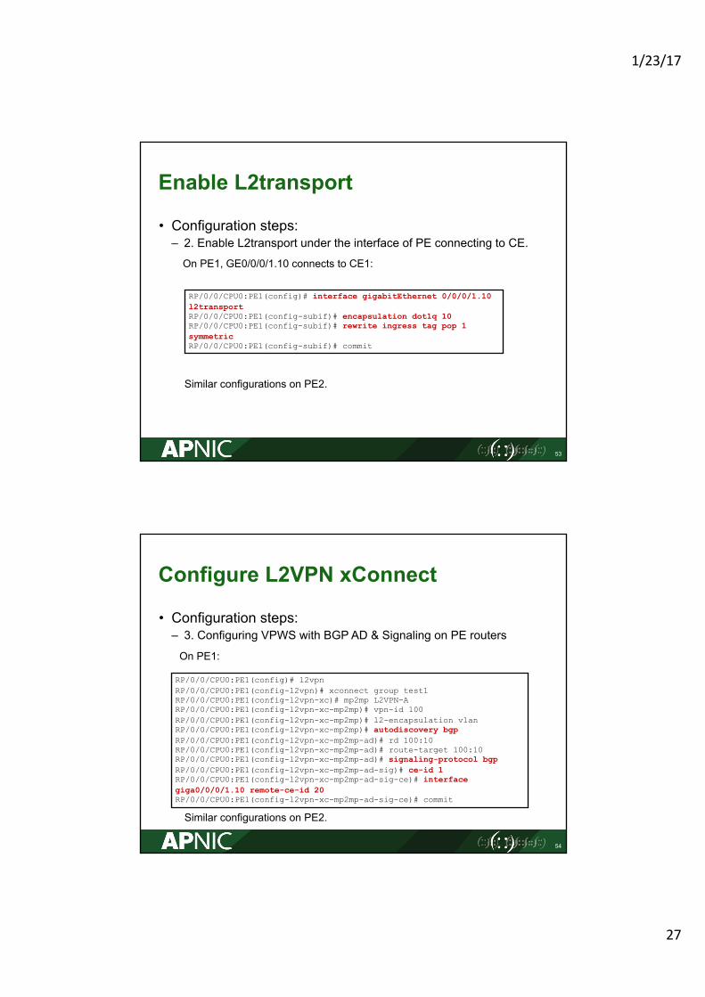
Enable L2transport
• Configuration steps:– 2. Enable L2transport under the interface of PE connecting to CE.
53
RP/0/0/CPU0:PE1(config)# interface gigabitEthernet 0/0/0/1.10 l2transportRP/0/0/CPU0:PE1(config-subif)# encapsulation dot1q 10RP/0/0/CPU0:PE1(config-subif)# rewrite ingress tag pop 1 symmetricRP/0/0/CPU0:PE1(config-subif)# commit
On PE1, GE0/0/0/1.10 connects to CE1:
Similar configurations on PE2.
Configure L2VPN xConnect
• Configuration steps:– 3. Configuring VPWS with BGP AD & Signaling on PE routers
54
RP/0/0/CPU0:PE1(config)# l2vpnRP/0/0/CPU0:PE1(config-l2vpn)# xconnect group test1RP/0/0/CPU0:PE1(config-l2vpn-xc)# mp2mp L2VPN-ARP/0/0/CPU0:PE1(config-l2vpn-xc-mp2mp)# vpn-id 100RP/0/0/CPU0:PE1(config-l2vpn-xc-mp2mp)# l2-encapsulation vlanRP/0/0/CPU0:PE1(config-l2vpn-xc-mp2mp)# autodiscovery bgpRP/0/0/CPU0:PE1(config-l2vpn-xc-mp2mp-ad)# rd 100:10RP/0/0/CPU0:PE1(config-l2vpn-xc-mp2mp-ad)# route-target 100:10RP/0/0/CPU0:PE1(config-l2vpn-xc-mp2mp-ad)# signaling-protocol bgpRP/0/0/CPU0:PE1(config-l2vpn-xc-mp2mp-ad-sig)# ce-id 1RP/0/0/CPU0:PE1(config-l2vpn-xc-mp2mp-ad-sig-ce)# interface giga0/0/0/1.10 remote-ce-id 20RP/0/0/CPU0:PE1(config-l2vpn-xc-mp2mp-ad-sig-ce)# commit
On PE1:
Similar configurations on PE2.
1/23/17
28
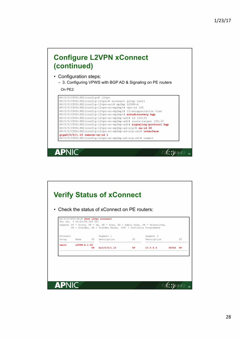
Configure L2VPN xConnect(continued)• Configuration steps:– 3. Configuring VPWS with BGP AD & Signaling on PE routers
55
RP/0/0/CPU0:PE2(config)# l2vpnRP/0/0/CPU0:PE2(config-l2vpn)# xconnect group test1RP/0/0/CPU0:PE2(config-l2vpn-xc)# mp2mp L2VPN-ARP/0/0/CPU0:PE2(config-l2vpn-xc-mp2mp)# vpn-id 100RP/0/0/CPU0:PE2(config-l2vpn-xc-mp2mp)# l2-encapsulation vlanRP/0/0/CPU0:PE2(config-l2vpn-xc-mp2mp)# autodiscovery bgpRP/0/0/CPU0:PE2(config-l2vpn-xc-mp2mp-ad)# rd 100:20RP/0/0/CPU0:PE2(config-l2vpn-xc-mp2mp-ad)# route-target 100:10RP/0/0/CPU0:PE2(config-l2vpn-xc-mp2mp-ad)# signaling-protocol bgpRP/0/0/CPU0:PE2(config-l2vpn-xc-mp2mp-ad-sig)# ce-id 20RP/0/0/CPU0:PE2(config-l2vpn-xc-mp2mp-ad-sig-ce)# interface giga0/0/0/1.10 remote-ce-id 1RP/0/0/CPU0:PE1(config-l2vpn-xc-mp2mp-ad-sig-ce)# commit
On PE2:
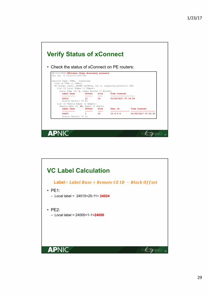
Verify Status of xConnect
• Check the status of xConnect on PE routers:
56
RP/0/0/CPU0:PE1# show l2vpn xconnectThu Jan 5 06:20:48.308 UTCLegend: ST = State, UP = Up, DN = Down, AD = Admin Down, UR = Unresolved,
SB = Standby, SR = Standby Ready, (PP) = Partially Programmed
XConnect Segment 1 Segment 2 Group Name ST Description ST Description ST ------------------------ ----------------------------- -----------------------------test1 L2VPN-A.1:20
UP Gi0/0/0/1.10 UP 10.0.0.4 65556 UP ----------------------------------------------------------------------------------------
1/23/17
29
Verify Status of xConnect
• Check the status of xConnect on PE routers:
57
RP/0/0/CPU0:PE1#show l2vpn discovery xconnectThu Jan 5 13:23:13.529 UTC
Service Type: VPWS, ConnectedList of VPNs (1 VPNs):XC Group: test1, MP2MP L2VPN-A, id: 0, signaling protocol: BGP
List of Local Edges (1 Edges):Local Edge ID: 1, Label Blocks (1 Blocks)
Label base Offset Size Time Created---------- ------ ---- -------------------24015 11 10 01/05/2017 07:16:04Status Vector: ff bf
List of Remote Edges (1 Edges):Remote Edge ID: 20, NLRIs (1 NLRIs)
Label base Offset Size Peer ID Time Created---------- ------ ---- --------------- -------------------24000 1 10 10.0.0.4 01/05/2017 07:23:35Status Vector: 7f ff
VC Label Calculation
• PE1: – Local label = 24015+20-11= 24024
• PE2:– Local label = 24000+1-1=24000
58
Label= 𝑳𝒂𝒃𝒆𝒍 𝑩𝒂𝒔𝒆 + 𝑹𝒆𝒎𝒐𝒕𝒆 𝑪𝑬 𝑰𝑫 − 𝑩𝒍𝒐𝒄𝒌 𝑶𝒇𝒇𝒔𝒆𝒕
1/23/17
30
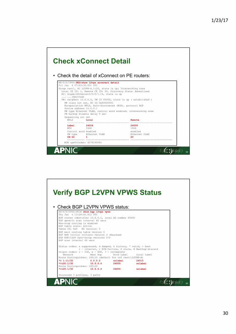
Check xConnect Detail
• Check the detail of xConnect on PE routers:
59
RP/0/0/CPU0:PE1#show l2vpn xconnect detailFri Jan 6 07:03:35.531 UTCGroup test1, XC L2VPN-A.1:20, state is up; Interworking none
Local CE ID: 1, Remote CE ID: 20, Discovery State: AdvertisedAC: GigabitEthernet0/0/0/1.10, state is up... ...(Omitted)PW: neighbor 10.0.0.4, PW ID 65556, state is up ( established )
PW class not set, XC ID 0xff000001Encapsulation MPLS, Auto-discovered (BGP), protocol BGPSource address 10.0.0.1PW type Ethernet VLAN, control word enabled, interworking nonePW backup disable delay 0 secSequencing not set
MPLS Local Remote------------ ------------------------------ -----------------------------Label 24024 24000MTU 1500 1500 Control word enabled enabledPW type Ethernet VLAN Ethernet VLANCE-ID 1 20 ------------ ------------------------------ -----------------------------
MIB cpwVcIndex: 4278190081
Verify BGP L2VPN VPWS Status
• Check BGP L2VPN VPWS status:
60
RP/0/0/CPU0:PE1# show bgp l2vpn vpwsThu Jan 5 13:24:55.912 UTCBGP router identifier 10.0.0.1, local AS number 65000BGP generic scan interval 60 secsNon-stop routing is enabledBGP table state: ActiveTable ID: 0x0 RD version: 0BGP main routing table version 5BGP NSR Initial initsync version 3 (Reached)BGP NSR/ISSU Sync-Group versions 0/0BGP scan interval 60 secs
Status codes: s suppressed, d damped, h history, * valid, > besti - internal, r RIB-failure, S stale, N Nexthop-discard
Origin codes: i - IGP, e - EGP, ? - incompleteNetwork Next Hop Rcvd Label Local Label
Route Distinguisher: 100:10 (default for vrf test1:L2VPN-A)*> 1:11/32 0.0.0.0 nolabel 24015*>i20:1/32 10.0.0.4 24000 nolabelRoute Distinguisher: 100:20*>i20:1/32 10.0.0.4 24000 nolabel
Processed 3 prefixes, 3 paths
1/23/17
31
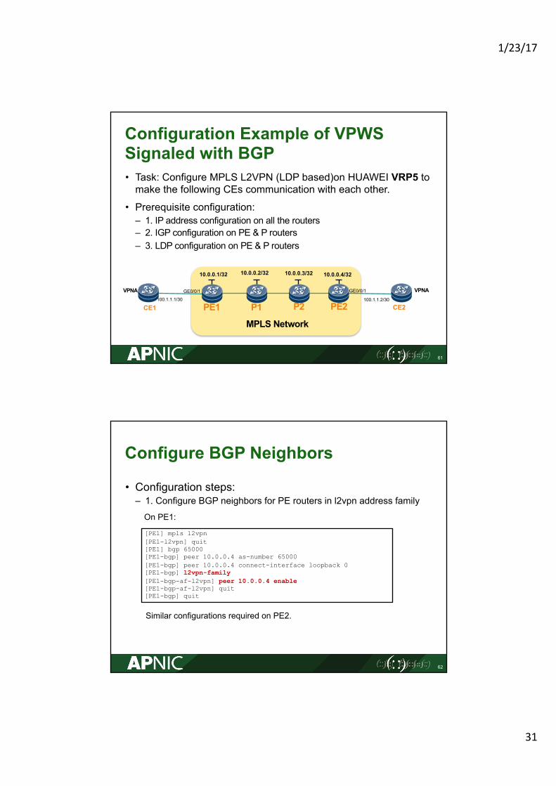
Configuration Example of VPWS Signaled with BGP • Task: Configure MPLS L2VPN (LDP based)on HUAWEI VRP5 to make the following CEs communication with each other.
• Prerequisite configuration:– 1. IP address configuration on all the routers– 2. IGP configuration on PE & P routers– 3. LDP configuration on PE & P routers
61
PE1
MPLS Network
PE2P1 P2CE1 CE2
VPNA VPNA100.1.1.1/30
10.0.0.1/32 10.0.0.2/32 10.0.0.3/32 10.0.0.4/32
100.1.1.2/30
GE0/0/1 GE0/0/1
Configure BGP Neighbors
• Configuration steps:– 1. Configure BGP neighbors for PE routers in l2vpn address family
62
[PE1] mpls l2vpn [PE1-l2vpn] quit [PE1] bgp 65000 [PE1-bgp] peer 10.0.0.4 as-number 65000[PE1-bgp] peer 10.0.0.4 connect-interface loopback 0 [PE1-bgp] l2vpn-family[PE1-bgp-af-l2vpn] peer 10.0.0.4 enable[PE1-bgp-af-l2vpn] quit [PE1-bgp] quit
On PE1:
Similar configurations required on PE2.
1/23/17
32
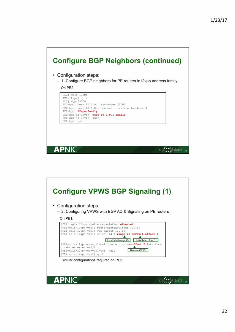
Configure BGP Neighbors (continued)
• Configuration steps:– 1. Configure BGP neighbors for PE routers in l2vpn address family
63
[PE2] mpls l2vpn [PE2-l2vpn] quit [PE2] bgp 65000 [PE2-bgp] peer 10.0.0.1 as-number 65000[PE2-bgp] peer 10.0.0.1 connect-interface loopback 0 [PE2-bgp] l2vpn-family[PE2-bgp-af-l2vpn] peer 10.0.0.1 enable[PE2-bgp-af-l2vpn] quit [PE2-bgp] quit
On PE2:
Configure VPWS BGP Signaling (1)
• Configuration steps:– 2. Configuring VPWS with BGP AD & Signaling on PE routers
64
[PE1] mpls l2vpn vpn1 encapsulation ethernet[PE1-mpls-l2vpn-vpn1] route-distinguisher 100:10 [PE1-mpls-l2vpn-vpn1] vpn-target 100:10 [PE1-mpls-l2vpn-vpn1] ce ce1 id 1 range 25 default-offset 1
[PE1-mpls-l2vpn-ce-vpn1-ce1] connection ce-offset 2 interface gigabitethernet 0/0/1 [PE1-mpls-l2vpn-ce-vpn1-ce1] quit [PE1-mpls-l2vpn-vpn1] quit
On PE1:
Remote CE ID
Local label range 25 Initial label offset 1
Similar configurations required on PE2.
1/23/17
33
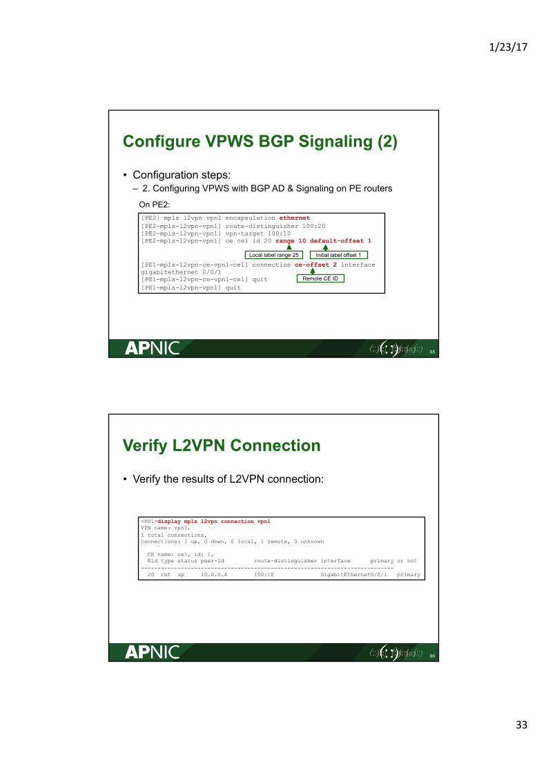
Configure VPWS BGP Signaling (2)
• Configuration steps:– 2. Configuring VPWS with BGP AD & Signaling on PE routers
65
[PE2] mpls l2vpn vpn1 encapsulation ethernet[PE2-mpls-l2vpn-vpn1] route-distinguisher 100:20 [PE2-mpls-l2vpn-vpn1] vpn-target 100:10 [PE2-mpls-l2vpn-vpn1] ce ce1 id 20 range 10 default-offset 1
[PE1-mpls-l2vpn-ce-vpn1-ce1] connection ce-offset 2 interface gigabitethernet 0/0/1 [PE1-mpls-l2vpn-ce-vpn1-ce1] quit [PE1-mpls-l2vpn-vpn1] quit
On PE2:
Remote CE ID
Local label range 25 Initial label offset 1
Verify L2VPN Connection
• Verify the results of L2VPN connection:
66
<PE1>display mpls l2vpn connection vpn1VPN name: vpn1, 1 total connections, connections: 1 up, 0 down, 0 local, 1 remote, 0 unknown
CE name: ce1, id: 1,Rid type status peer-id route-distinguisher interface primary or not
----------------------------------------------------------------------------20 rmt up 10.0.0.4 100:10 GigabitEthernet0/0/1 primary
1/23/17
34
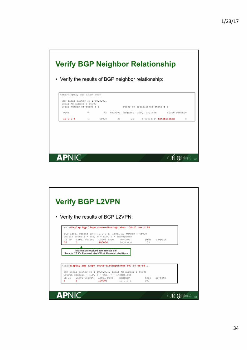
Verify BGP Neighbor Relationship
• Verify the results of BGP neighbor relationship:
67
<PE1>display bgp l2vpn peer
BGP local router ID : 10.0.0.1Local AS number : 65000Total number of peers : 1 Peers in established state : 1
Peer V AS MsgRcvd MsgSent OutQ Up/Down State PrefRcv
10.0.0.4 4 65000 20 26 0 00:14:44 Established 0
Verify BGP L2VPN
• Verify the results of BGP L2VPN:
68
<PE1>display bgp l2vpn route-distinguisher 100:20 ce-id 20
BGP Local router ID : 10.0.0.1, local AS number : 65000Origin codes:i - IGP, e - EGP, ? - incompleteCE ID Label Offset Label Base nexthop pref as-path20 1 100006 10.0.0.4 100
Information received from remote site:Remote CE ID, Remote Label Offset, Remote Label Base
<PE2>display bgp l2vpn route-distinguisher 100:10 ce-id 1
BGP Local router ID : 10.0.0.4, local AS number : 65000Origin codes:i - IGP, e - EGP, ? - incompleteCE ID Label Offset Label Base nexthop pref as-path1 1 100001 10.0.0.1 100
1/23/17
35
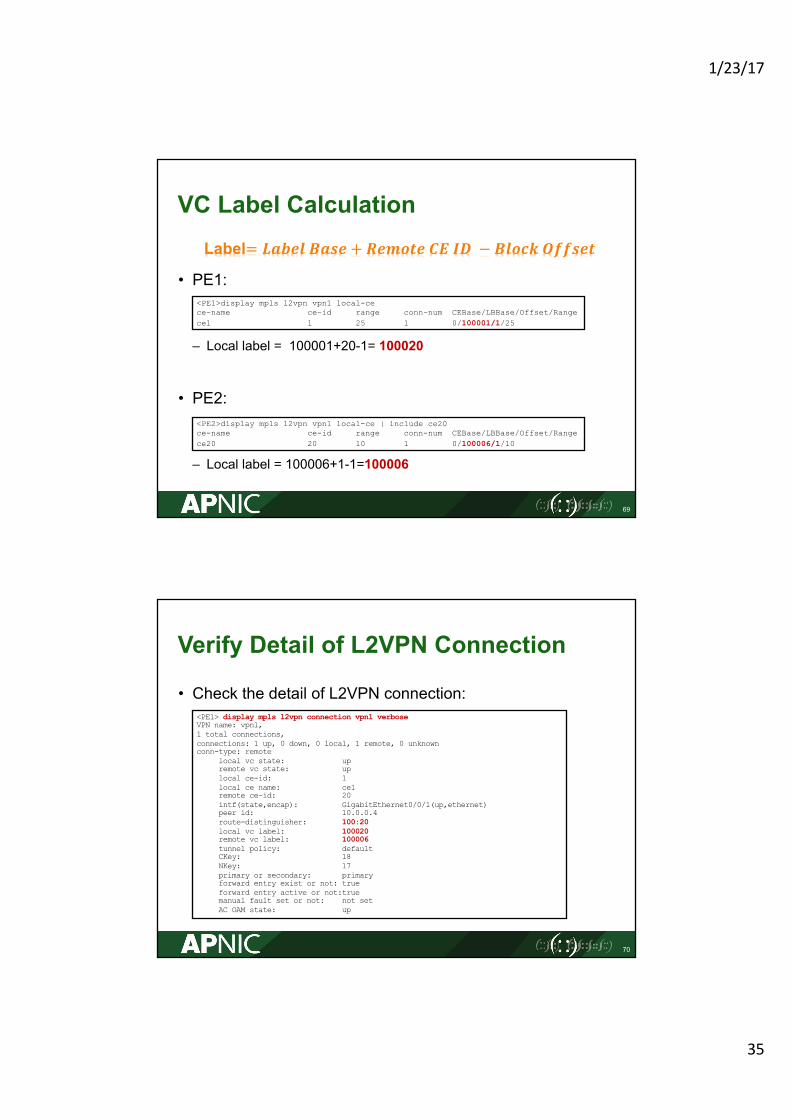
VC Label Calculation
• PE1:
– Local label = 100001+20-1= 100020
• PE2:
– Local label = 100006+1-1=100006
69
Label= 𝑳𝒂𝒃𝒆𝒍 𝑩𝒂𝒔𝒆 + 𝑹𝒆𝒎𝒐𝒕𝒆 𝑪𝑬 𝑰𝑫 − 𝑩𝒍𝒐𝒄𝒌 𝑶𝒇𝒇𝒔𝒆𝒕
<PE1>display mpls l2vpn vpn1 local-cece-name ce-id range conn-num CEBase/LBBase/Offset/Range ce1 1 25 1 0/100001/1/25
<PE2>display mpls l2vpn vpn1 local-ce | include ce20ce-name ce-id range conn-num CEBase/LBBase/Offset/Range ce20 20 10 1 0/100006/1/10
Verify Detail of L2VPN Connection
• Check the detail of L2VPN connection:
70
<PE1> display mpls l2vpn connection vpn1 verbose VPN name: vpn1, 1 total connections, connections: 1 up, 0 down, 0 local, 1 remote, 0 unknownconn-type: remote
local vc state: upremote vc state: uplocal ce-id: 1local ce name: ce1remote ce-id: 20intf(state,encap): GigabitEthernet0/0/1(up,ethernet)peer id: 10.0.0.4route-distinguisher: 100:20local vc label: 100020remote vc label: 100006tunnel policy: defaultCKey: 18NKey: 17primary or secondary: primaryforward entry exist or not: trueforward entry active or not:truemanual fault set or not: not setAC OAM state: up
1/23/17
36
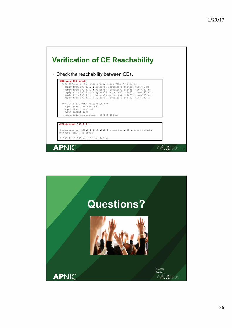
Verification of CE Reachability
• Check the reachability between CEs.
71
<CE2>ping 100.1.1.1PING 100.1.1.1: 56 data bytes, press CTRL_C to break
Reply from 100.1.1.1: bytes=56 Sequence=1 ttl=255 time=90 msReply from 100.1.1.1: bytes=56 Sequence=2 ttl=255 time=150 msReply from 100.1.1.1: bytes=56 Sequence=3 ttl=255 time=140 msReply from 100.1.1.1: bytes=56 Sequence=4 ttl=255 time=110 msReply from 100.1.1.1: bytes=56 Sequence=5 ttl=255 time=140 ms
--- 100.1.1.1 ping statistics ---5 packet(s) transmitted5 packet(s) received0.00% packet lossround-trip min/avg/max = 90/126/150 ms
<CE2>tracert 100.1.1.1
traceroute to 100.1.1.1(100.1.1.1), max hops: 30 ,packet length: 40,press CTRL_C to break
1 100.1.1.1 180 ms 130 ms 140 ms
Issue Date:
Revision:
Questions?