Embed Size (px)
DESCRIPTION
ndsjkfnkjdsaf
Citation preview
Module: IV Mine Fan - General
Dr. Nuhindro Priagung Widodo
Teknik Pertambangan
FakultasTeknik Pertambangan dan Perminyakan, Institut Teknologi Bandung
2009
NPW1
Mine Ventilation
Isi
NPW
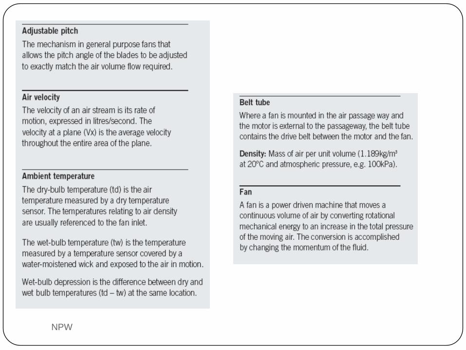
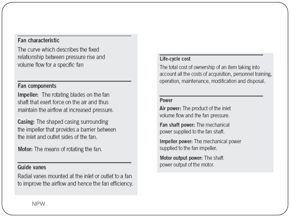
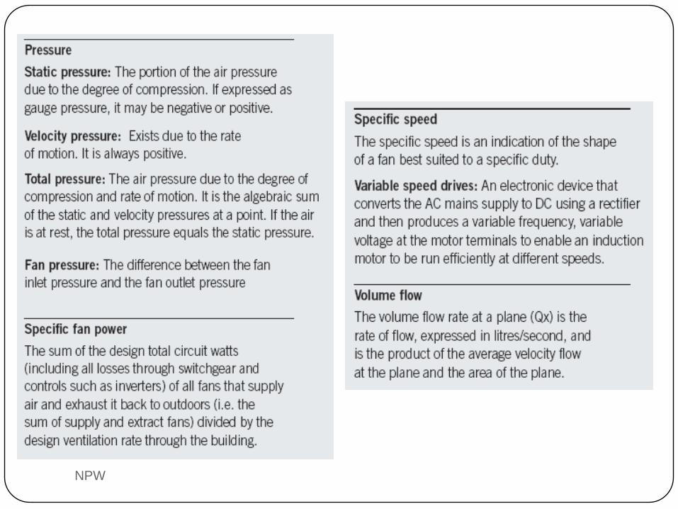
1. Pengertian dan istilah
2. Klasifikasi dan cara kerja alat ventilasi mekanis
- Fan sentrifugal
- Fan axial
- Mixed-flow fan
3. Kurva karakteristik fan
4. Hukum-hukum fan
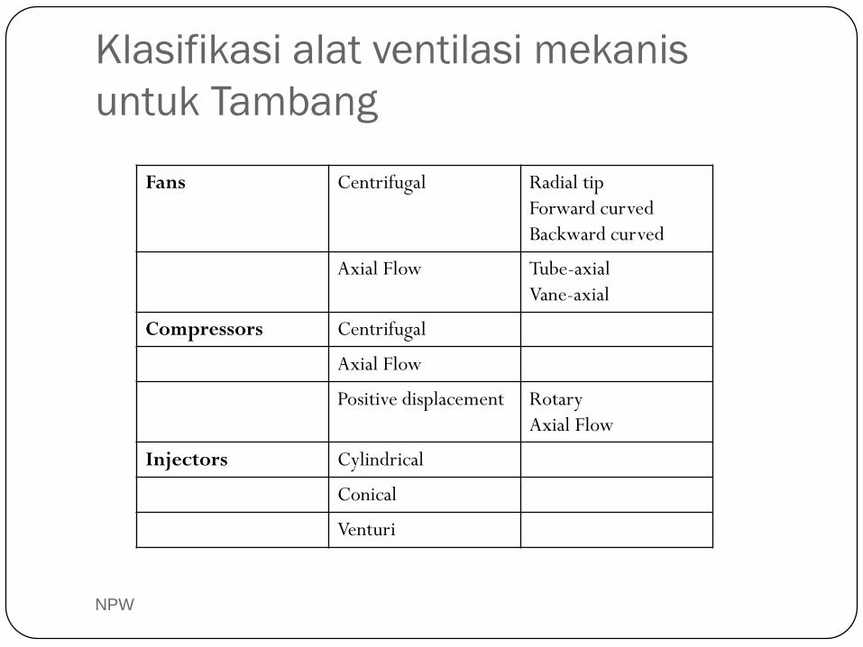
Klasifikasi alat ventilasi mekanis
untuk Tambang
NPW
Fans Centrifugal Radial tip
Forward curved
Backward curved
Axial Flow Tube-axial
Vane-axial
Compressors Centrifugal
Axial Flow
Positive displacement Rotary
Axial Flow
Injectors Cylindrical
Conical
Venturi
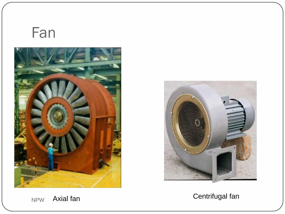
Fan
NPW Axial fan Centrifugal fan
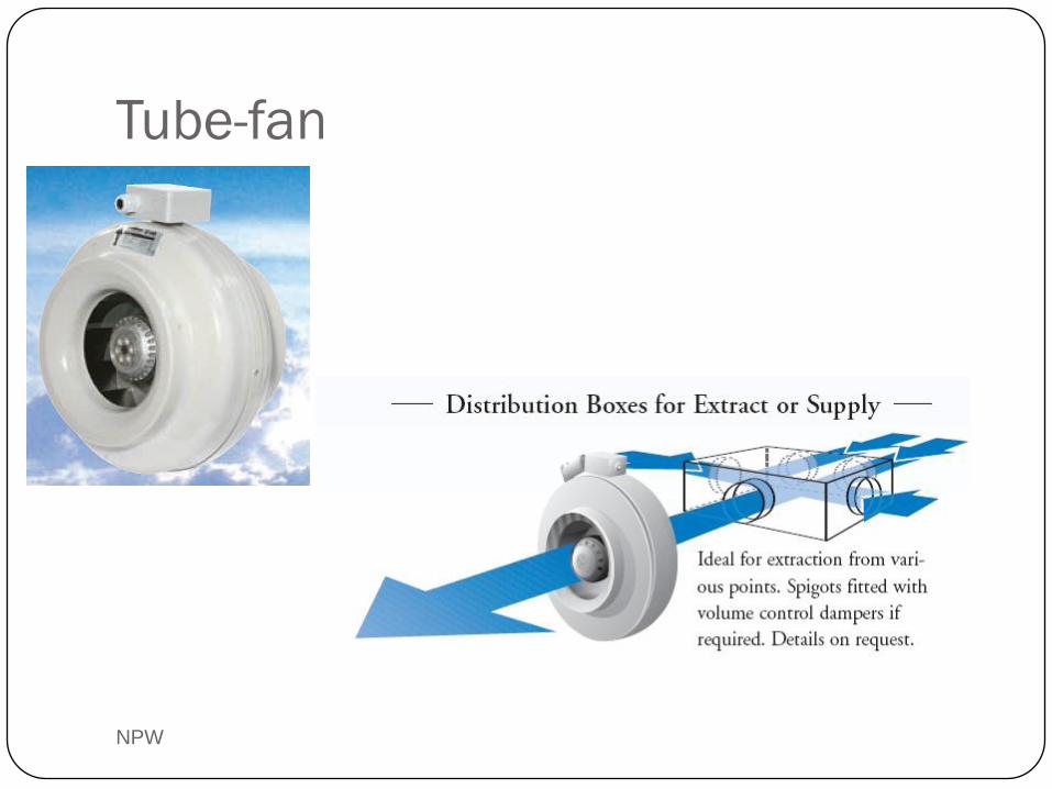
Tube-fan
NPW
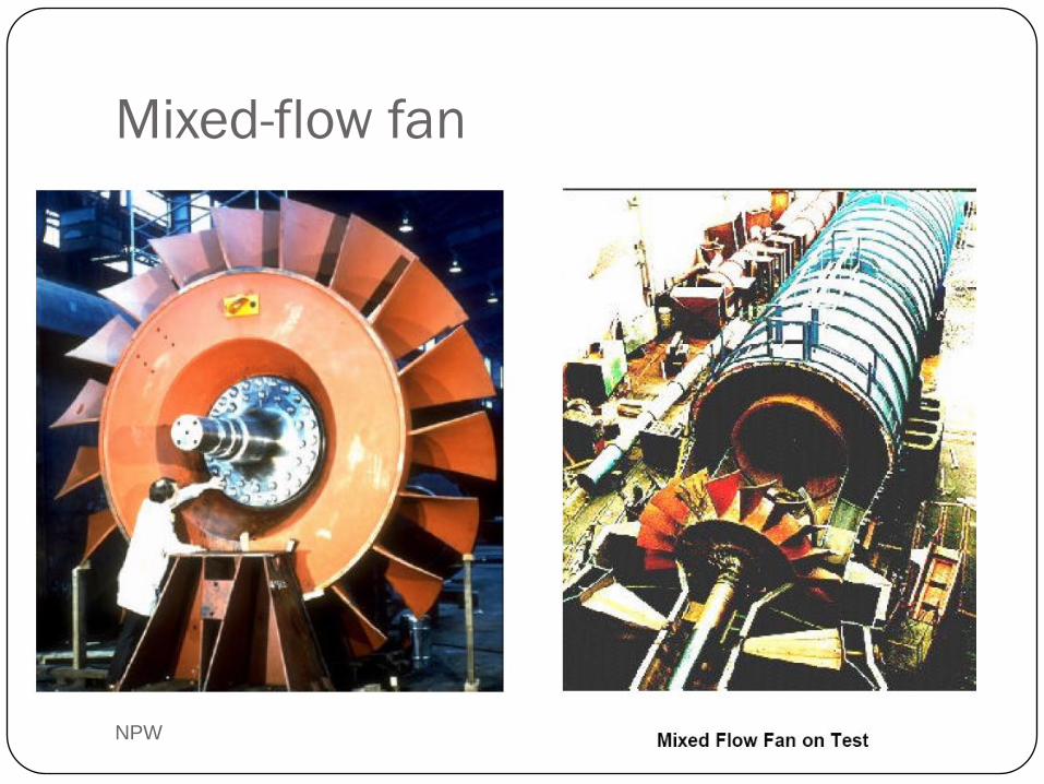
Mixed-flow fan
NPW
NPW
NPW
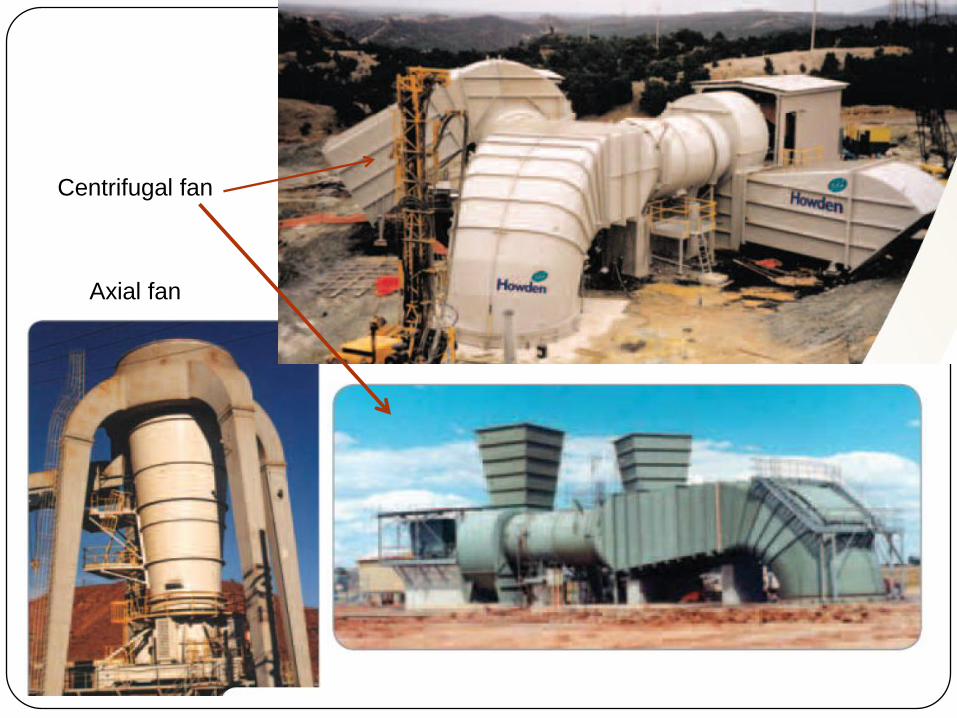
Axial fan
Centrifugal fan
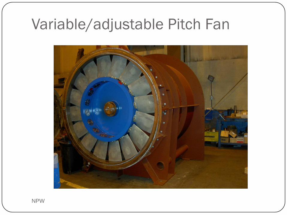
Variable/adjustable Pitch Fan
NPW
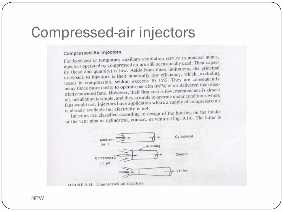
Compressed-air injectors
NPW
NPW
NPW
NPW
ASSESSMENT OF FANS AND BLOWERS
NPW
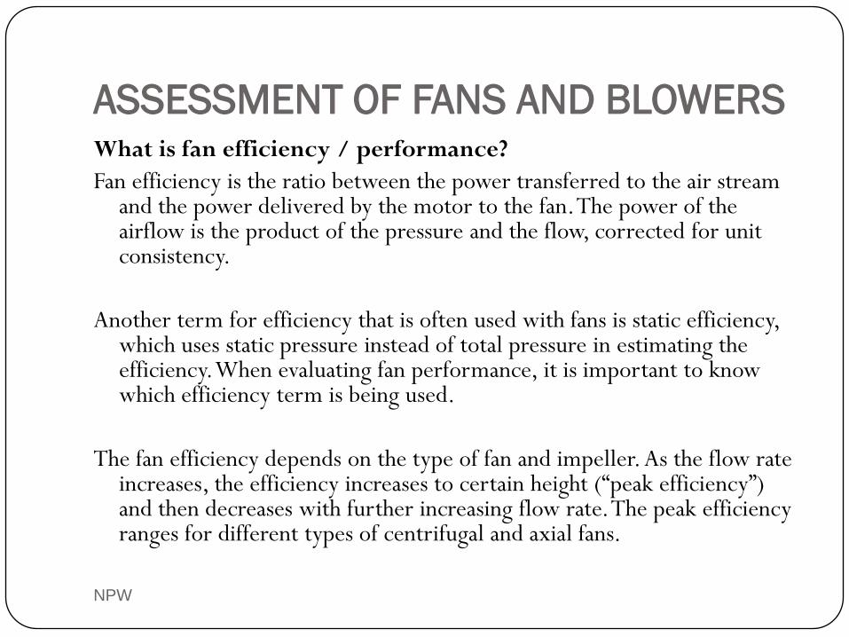
What is fan efficiency / performance?
Fan efficiency is the ratio between the power transferred to the air stream and the power delivered by the motor to the fan. The power of the airflow is the product of the pressure and the flow, corrected for unit consistency.
Another term for efficiency that is often used with fans is static efficiency, which uses static pressure instead of total pressure in estimating the efficiency. When evaluating fan performance, it is important to know which efficiency term is being used.
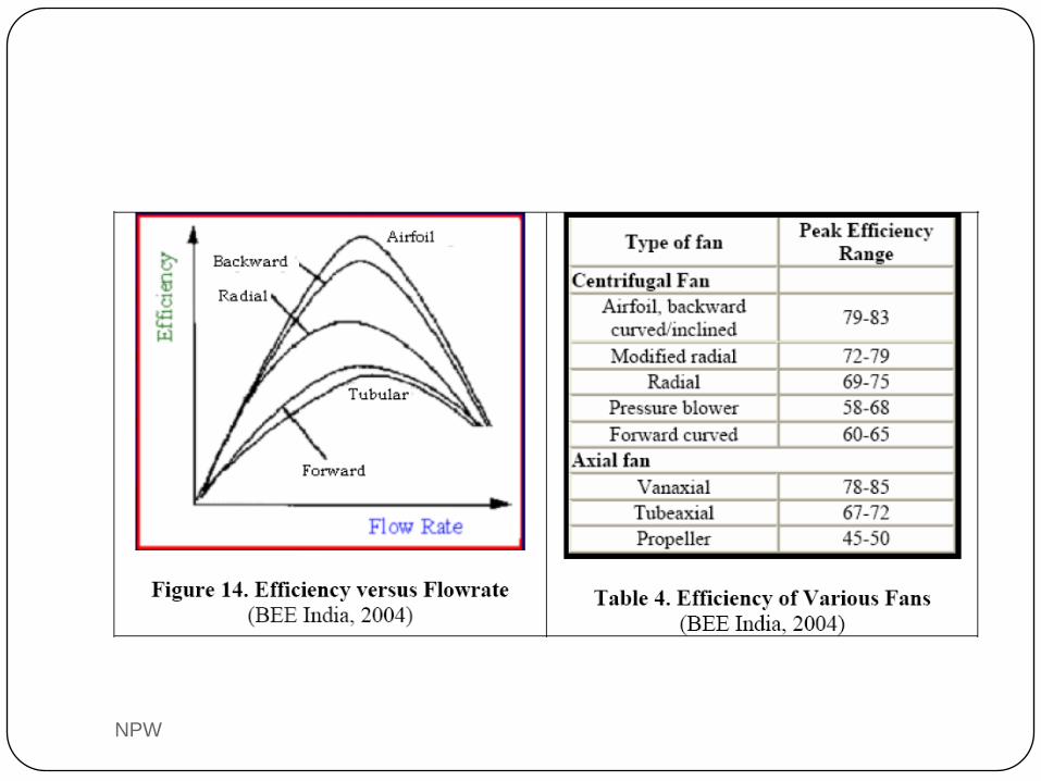
The fan efficiency depends on the type of fan and impeller. As the flow rate increases, the efficiency increases to certain height (“peak efficiency”) and then decreases with further increasing flow rate. The peak efficiency ranges for different types of centrifugal and axial fans.
NPW
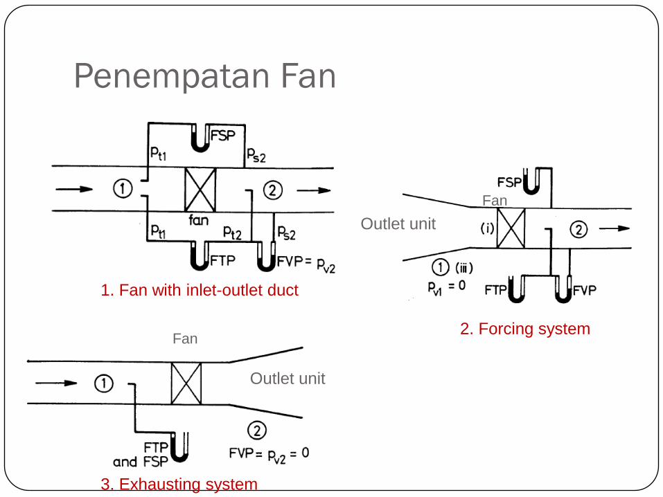
Penempatan Fan
NPW
2. Forcing system
3. Exhausting system
Fan
Outlet unit
Outlet unit
Fan
1. Fan with inlet-outlet duct
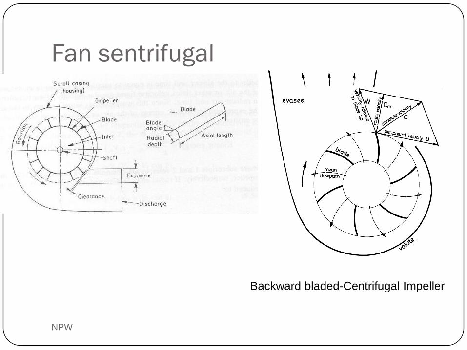
Fan sentrifugal
NPW
Backward bladed-Centrifugal Impeller
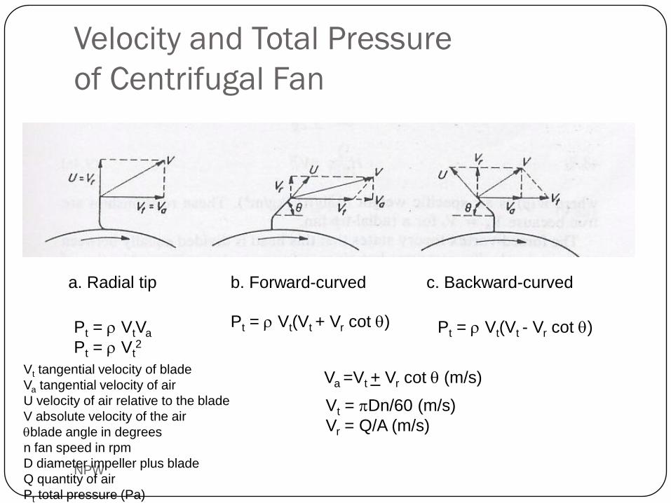
Velocity and Total Pressure
of Centrifugal Fan
NPW
a. Radial tip b. Forward-curved c. Backward-curved
Va =Vt + Vr cot q (m/s)
Pt = r Vt(Vt + Vr cot q)
Vt tangential velocity of blade
Va tangential velocity of air
U velocity of air relative to the blade
V absolute velocity of the air
qblade angle in degrees
n fan speed in rpm
D diameter impeller plus blade
Q quantity of air
Pt total pressure (Pa)
Pt = r Vt(Vt - Vr cot q)Pt = r VtVa
Pt = r Vt2
Vt = pDn/60 (m/s)
Vr = Q/A (m/s)
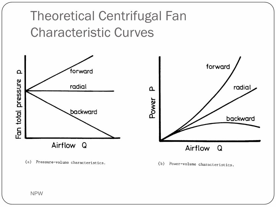
Theoretical Centrifugal Fan
Characteristic Curves
NPW
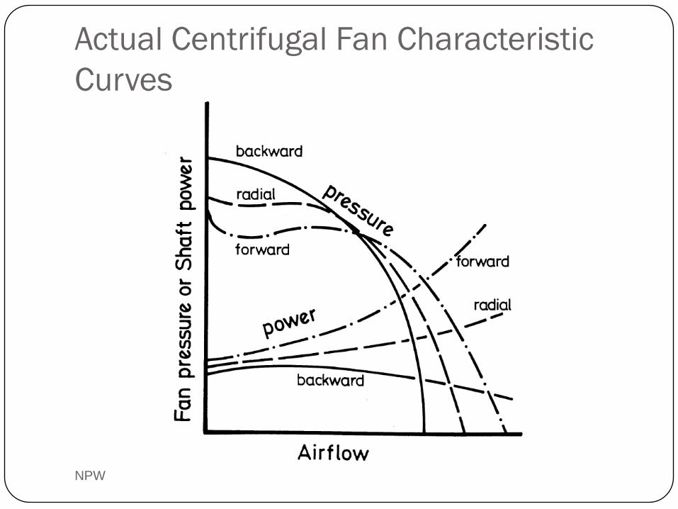
Actual Centrifugal Fan Characteristic
Curves
NPW
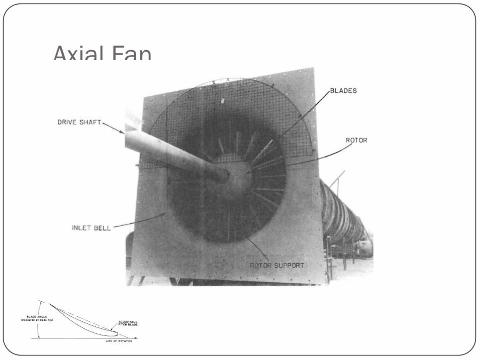
Axial Fan
NPW
NPW
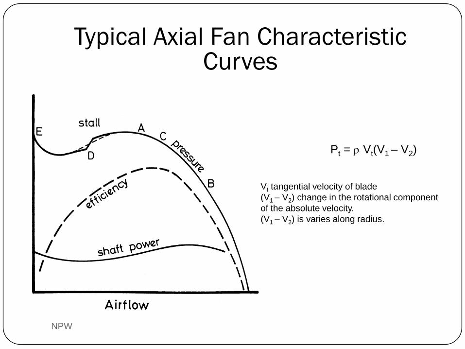
Pt = r Vt(V1 – V2)
Typical Axial Fan Characteristic Curves
Vt tangential velocity of blade
(V1 – V2) change in the rotational component
of the absolute velocity.
(V1 – V2) is varies along radius.
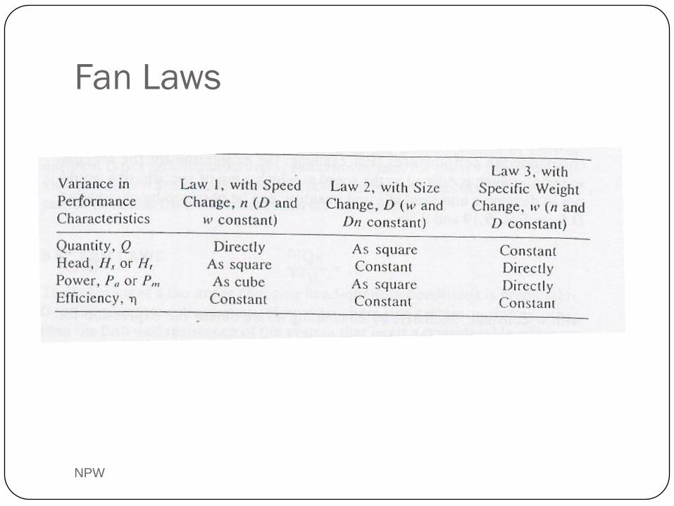
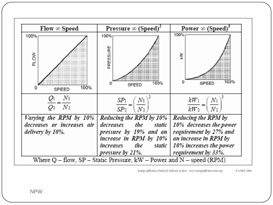
Fan Laws
NPW
NPW
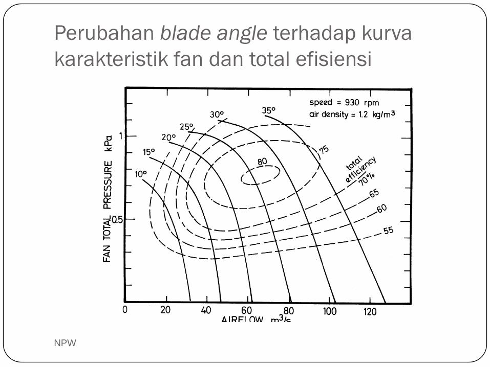
Perubahan blade angle terhadap kurva
karakteristik fan dan total efisiensi
NPW
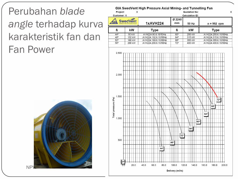
Perubahan blade
angle terhadap kurva
karakteristik fan dan
Fan Power
NPW
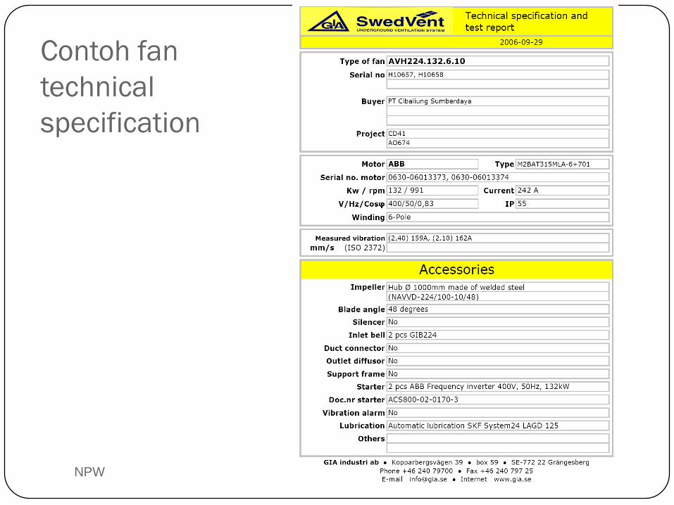
Contoh fan
technical
specification
NPW
Contra-rotating axial fan
NPW
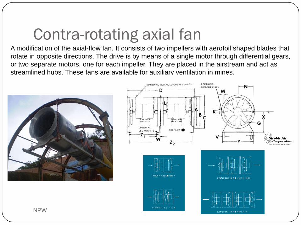
A modification of the axial-flow fan. It consists of two impellers with aerofoil shaped blades that
rotate in opposite directions. The drive is by means of a single motor through differential gears,
or two separate motors, one for each impeller. They are placed in the airstream and act as
streamlined hubs. These fans are available for auxiliary ventilation in mines.
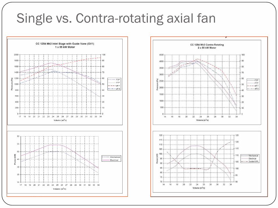
Single vs. Contra-rotating axial fan
NPW
NPW
NPW
NPW
NPW
NPW
NPW
NPW
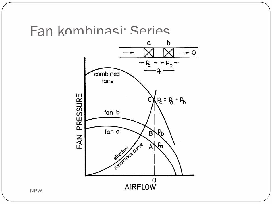
Fan kombinasi: Series
NPW
NPW
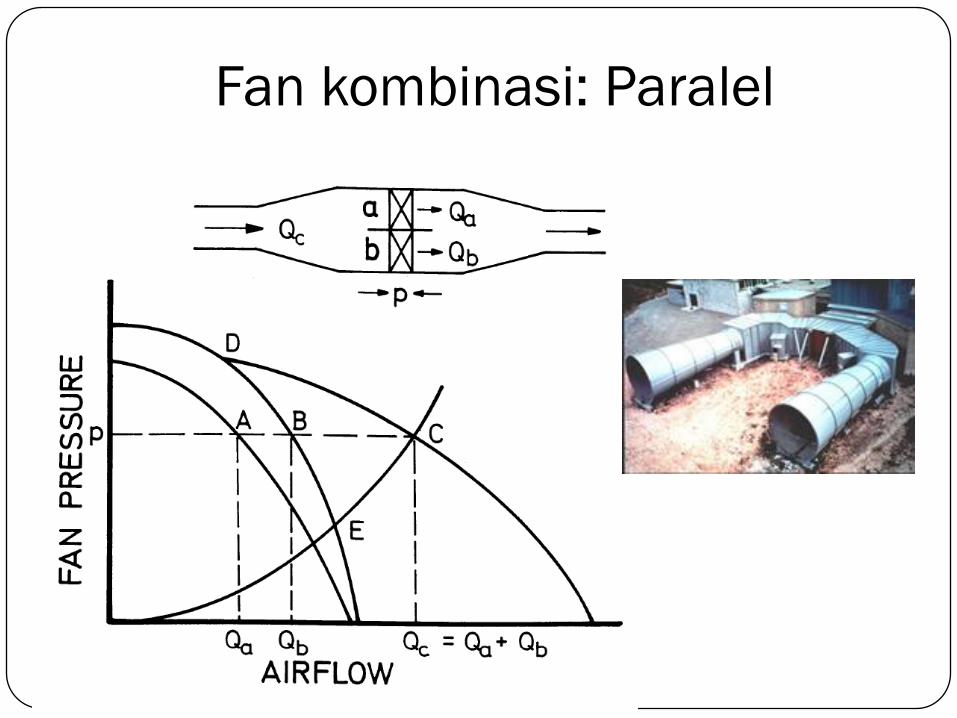
Fan kombinasi: Paralel
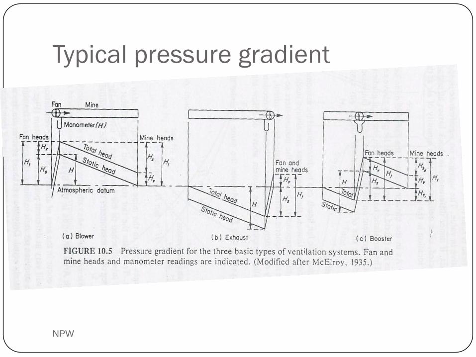
Typical pressure gradient
NPW
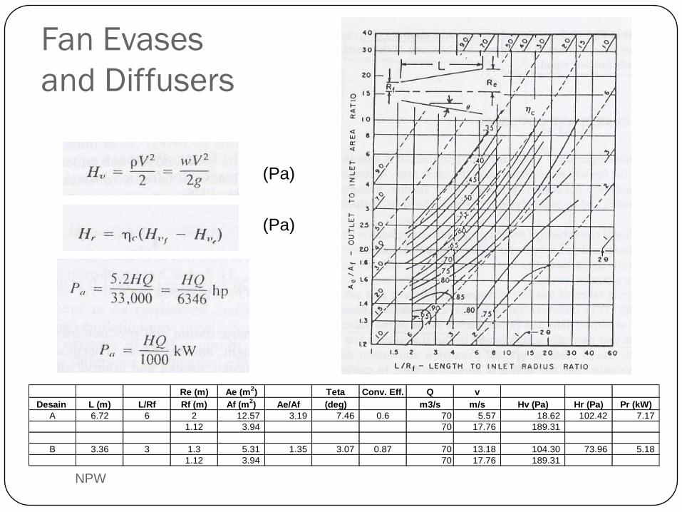
Fan Evases
and Diffusers
NPW
Re (m) Ae (m2) Teta Conv. Eff. Q v
Desain L (m) L/Rf Rf (m) Af (m2) Ae/Af (deg) m3/s m/s Hv (Pa) Hr (Pa) Pr (kW)
A 6.72 6 2 12.57 3.19 7.46 0.6 70 5.57 18.62 102.42 7.17
1.12 3.94 70 17.76 189.31
B 3.36 3 1.3 5.31 1.35 3.07 0.87 70 13.18 104.30 73.96 5.18
1.12 3.94 70 17.76 189.31
(Pa)
(Pa)
NPW
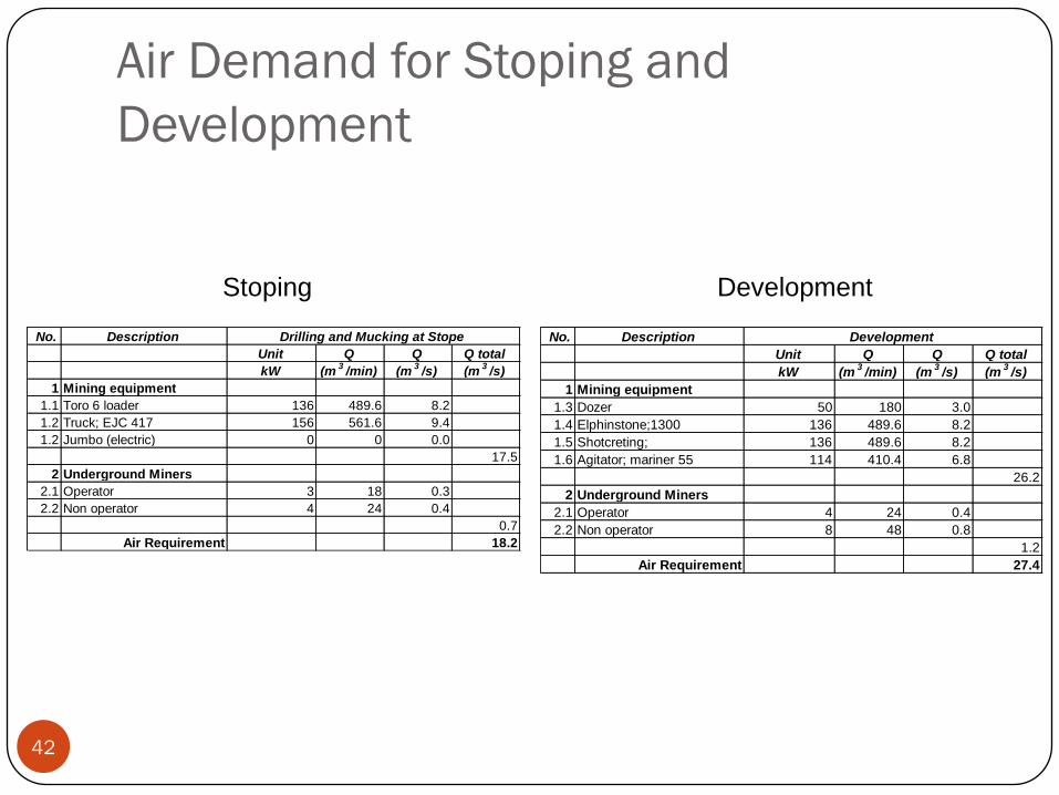
Air Demand for Stoping and
Development
42
Stoping Development
No. Description
Unit Q Q Q total
kW (m3
/min) (m3
/s) (m3
/s)
1 Mining equipment
1.1 Toro 6 loader 136 489.6 8.2
1.2 Truck; EJC 417 156 561.6 9.4
1.2 Jumbo (electric) 0 0 0.0
17.5
2 Underground Miners
2.1 Operator 3 18 0.3
2.2 Non operator 4 24 0.4
0.7
Air Requirement 18.2
Drilling and Mucking at Stope No. Description
Unit Q Q Q total
kW (m3
/min) (m3
/s) (m3
/s)
1 Mining equipment
1.3 Dozer 50 180 3.0
1.4 Elphinstone;1300 136 489.6 8.2
1.5 Shotcreting; 136 489.6 8.2
1.6 Agitator; mariner 55 114 410.4 6.8
26.2
2 Underground Miners
2.1 Operator 4 24 0.4
2.2 Non operator 8 48 0.8
1.2
Air Requirement 27.4
Development
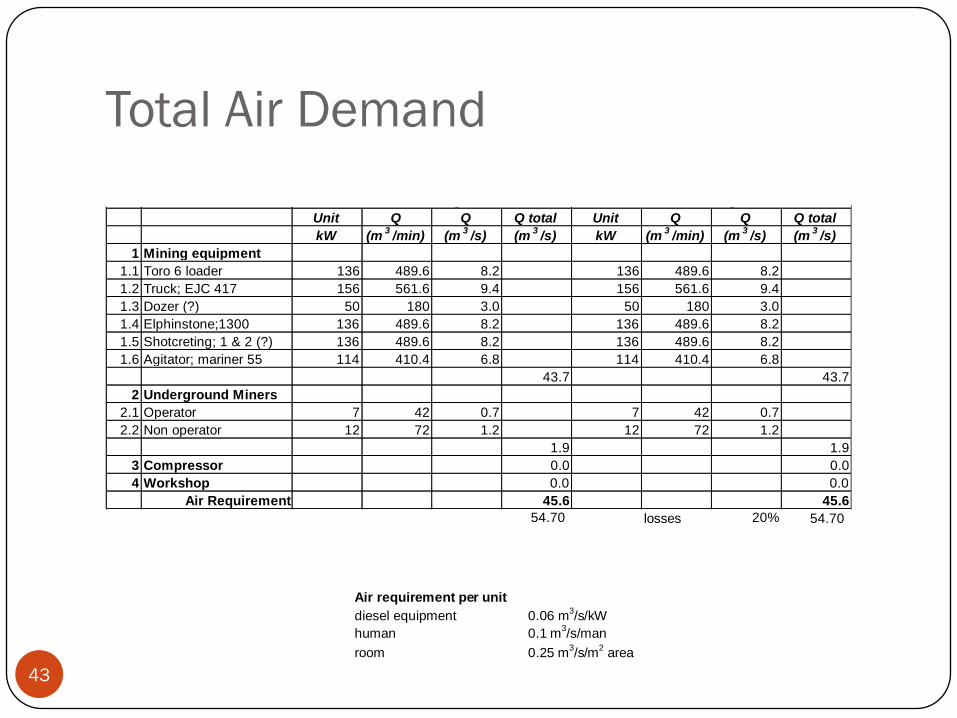
Total Air Demand
43
Air requirement per unit diesel equipment 0.06 m
3/s/kW
human 0.1 m3/s/man
room 0.25 m3/s/m
2 area
No. Description
Unit Q Q Q total Unit Q Q Q total
kW (m3
/min) (m3
/s) (m3
/s) kW (m3
/min) (m3
/s) (m3
/s)
1 Mining equipment
1.1 Toro 6 loader 136 489.6 8.2 136 489.6 8.2
1.2 Truck; EJC 417 156 561.6 9.4 156 561.6 9.4
1.3 Dozer (?) 50 180 3.0 50 180 3.0
1.4 Elphinstone;1300 136 489.6 8.2 136 489.6 8.2
1.5 Shotcreting; 1 & 2 (?) 136 489.6 8.2 136 489.6 8.2
1.6 Agitator; mariner 55 114 410.4 6.8 114 410.4 6.8
43.7 43.7
2 Underground Miners
2.1 Operator 7 42 0.7 7 42 0.7
2.2 Non operator 12 72 1.2 12 72 1.2
1.9 1.9
3 Compressor 0.0 0.0
4 Workshop 0.0 0.0
Air Requirement 45.6 45.6
54.70 losses 20% 54.70
Cikoneng Cibitung
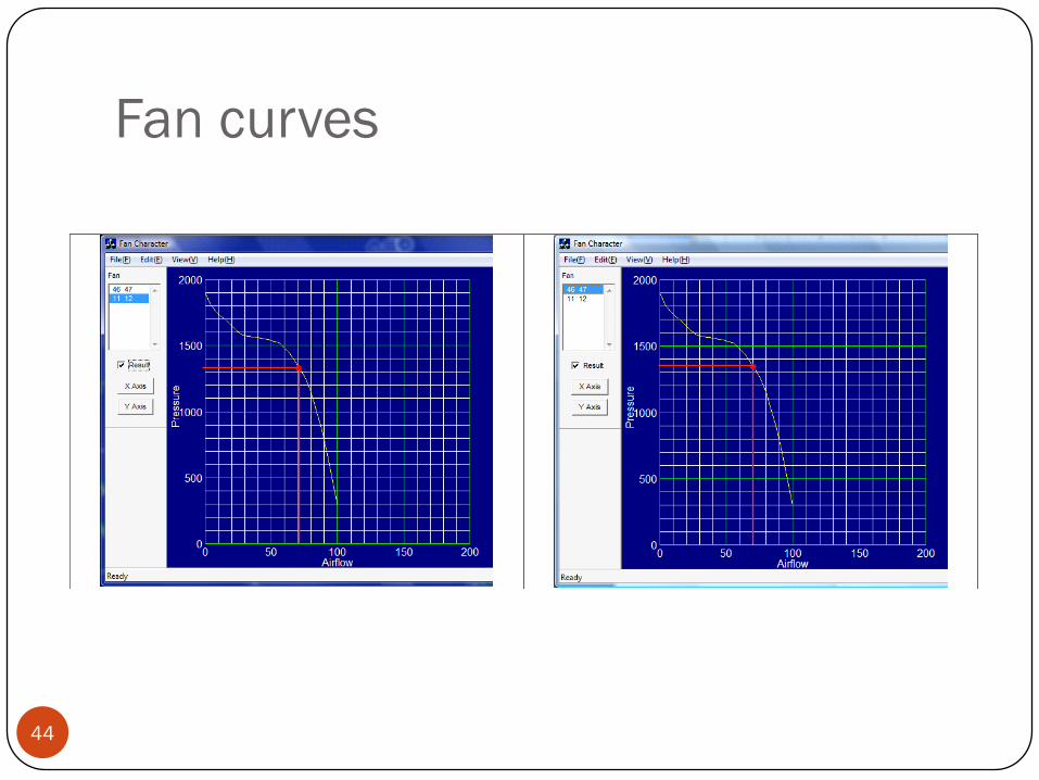
Fan curves
44
Cikoneng
Cibitung
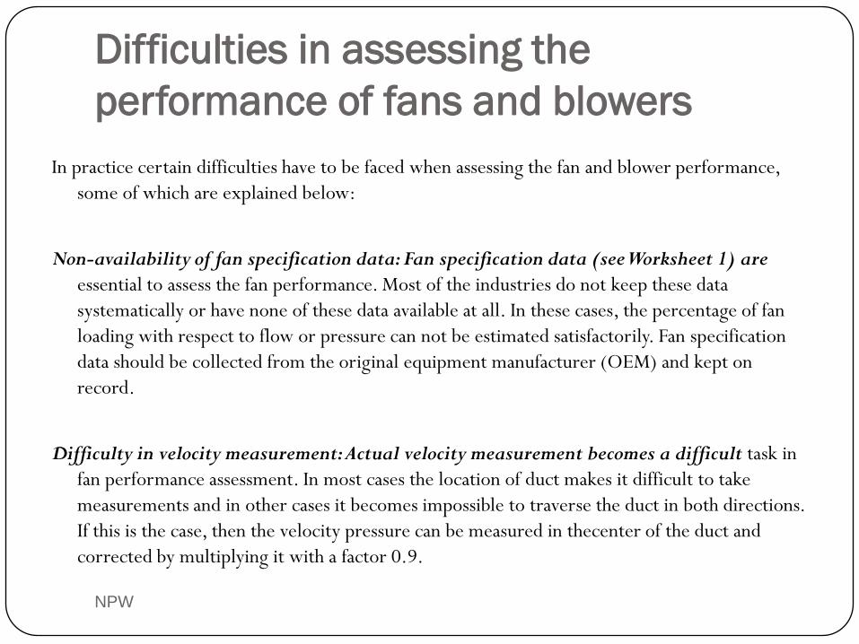
Difficulties in assessing the
performance of fans and blowers
NPW
In practice certain difficulties have to be faced when assessing the fan and blower performance,
some of which are explained below:
Non-availability of fan specification data: Fan specification data (see Worksheet 1) are
essential to assess the fan performance. Most of the industries do not keep these data
systematically or have none of these data available at all. In these cases, the percentage of fan
loading with respect to flow or pressure can not be estimated satisfactorily. Fan specification
data should be collected from the original equipment manufacturer (OEM) and kept on
record.
Difficulty in velocity measurement: Actual velocity measurement becomes a difficult task in
fan performance assessment. In most cases the location of duct makes it difficult to take
measurements and in other cases it becomes impossible to traverse the duct in both directions.
If this is the case, then the velocity pressure can be measured in thecenter of the duct and
corrected by multiplying it with a factor 0.9.
NPW
Improper calibration of the pitot tube, manometer,
anemometer & measuring instruments: All instruments and
other power measuring instruments should be calibrated correctly
to avoid an incorrect assessment of fans and blowers.
Assessments should not be carried out by applying correction
factors to compensate for this.
Variation of process parameters during tests: If there is a
large variation of process parameters measured during test
periods, then the performance assessment becomes
unreliable.
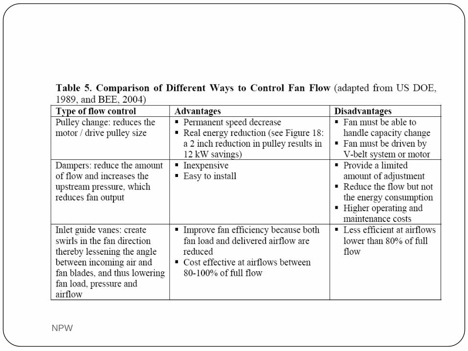
Choose the right fan
NPW
Important considerations when selecting a fan are (US DOE, 1989):
• Noise
• Rotational speed
• Air stream characteristics
• Temperature range
• Variations in operating conditions
• Space constraints and system layout
• Purchase costs, operating costs (determined by efficiency and maintenance), and operating life
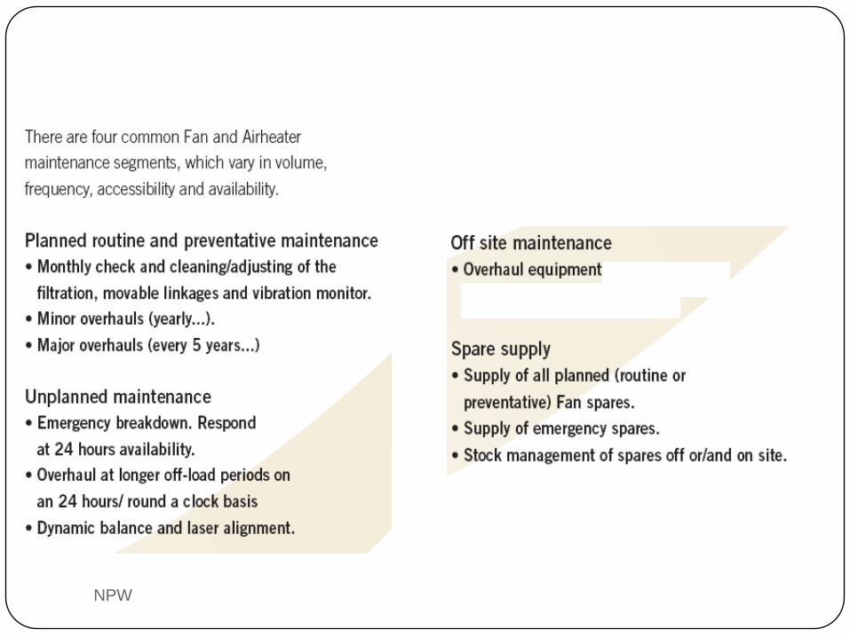
Maintain fans regularly
NPW
Regular maintenance of fans is important to maintain their
performance levels. Maintenance activities include (US DOE,
1989):
• Periodic inspection of all system components
• Bearing lubrication and replacement
• Belt tightening and replacement
• Motor repair or replacement
• Fan cleaning
NPW
NPW
NPW
NPW