Embed Size (px)
Citation preview

QS Smart Power
Supply Panel
Installation
Instructions
QSPS-P1-10-60
English
Page 1
Sivoia® QS QSPS-P1-10-60 Installation instructions
QSPS-P1-10-60 Input: 120 V 60 Hz 8 A (35% duty cycle)
Output: 24 V 2.5 A per output (35% duty cycle)
Input: 120 V 60 Hz 4.6 A continuous
Output: 24 V 1 A continuous per output
Installation Instructions (Save these instructions)
Read and Follow all instructions.
Tools Required:
Wire Cutter/Stripper Power Drill
Small Flat-Head Screwdriver #2 Phillips Screwdriver
NOTE: Mounting hardware is not included due to the wide variety of wall materials.
Customer should determine the appropriate mounting hardware for their specifi c needs.
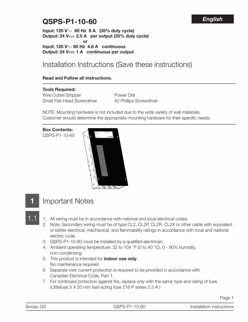
Box Contents:
QSPS-P1-10-60
Important Notes
1. All wiring must be in accordance with national and local electrical codes.
2. Note: Secondary wiring must be of type CL2, CL2P, CL2R, CL2X or other cable with equivalent
or better electrical, mechanical, and fl ammability ratings in accordance with local and national
electric code.
3. QSPS-P1-10-60 must be installed by a qualifi ed electrician.
4. Ambient operating temperature: 32 to 104 °F (0 to 40 °C), 0 - 90% humidity,
non-condensing.
5. This product is intended for indoor use only.
No maintenance required.
6. Separate over current protection is required to be provided in accordance with
Canadian Electrical Code, Part 1.
7. For continued protection against fi re, replace only with the same type and rating of fuse.
(Littlefuse 5 X 20 mm fast-acting fuse 216 P series 2.5 A )
1
1.1
or
English
Page 2
Sivoia® QS QSPS-P1-10-60 Installation instructions
2
2.1
Installation
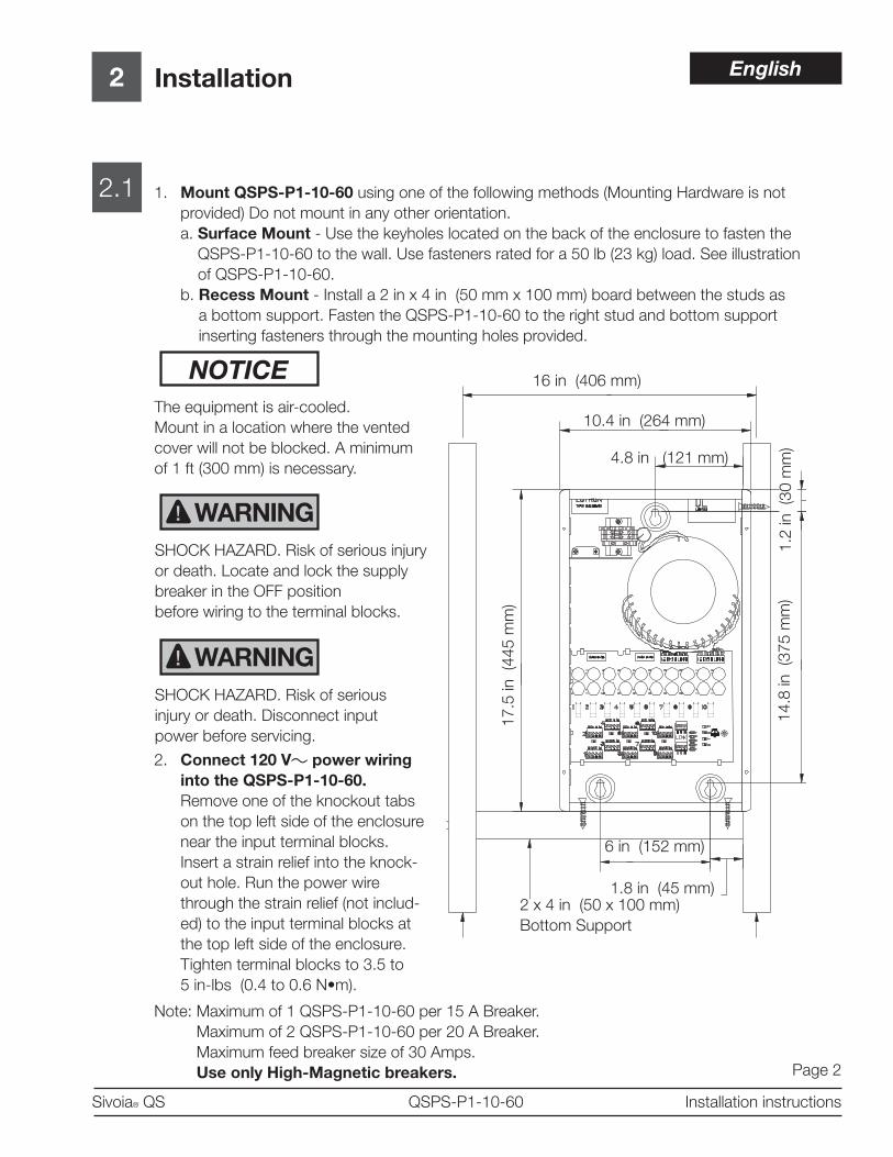
1. Mount QSPS-P1-10-60 using one of the following methods (Mounting Hardware is not
provided) Do not mount in any other orientation.
a. Surface Mount - Use the keyholes located on the back of the enclosure to fasten the
QSPS-P1-10-60 to the wall. Use fasteners rated for a 50 lb (23 kg) load. See illustration
of QSPS-P1-10-60.
b. Recess Mount - Install a 2 in x 4 in (50 mm x 100 mm) board between the studs as
a bottom support. Fasten the QSPS-P1-10-60 to the right stud and bottom support
inserting fasteners through the mounting holes provided.
NOTICE
The equipment is air-cooled.
Mount in a location where the vented
cover will not be blocked. A minimum
of 1 ft (300 mm) is necessary.
WARNING
SHOCK HAZARD. Risk of serious injury
or death. Locate and lock the supply
breaker in the OFF position
before wiring to the terminal blocks.
WARNING
SHOCK HAZARD. Risk of serious
injury or death. Disconnect input
power before servicing.
16 in (406 mm)
10.4 in (264 mm)
4.8 in (121 mm)
1.2
in
(30 m
m)
14.8
in
(375 m
m)
17.5
in
(445 m
m)
6 in (152 mm)
1.8 in (45 mm)2 x 4 in (50 x 100 mm)
Bottom Support
2. Connect 120 V power wiring
into the QSPS-P1-10-60.
Remove one of the knockout tabs
on the top left side of the enclosure
near the input terminal blocks.
Insert a strain relief into the knock-
out hole. Run the power wire
through the strain relief (not includ-
ed) to the input terminal blocks at
the top left side of the enclosure.
Tighten terminal blocks to 3.5 to
5 in-lbs (0.4 to 0.6 N•m).
Note: Maximum of 1 QSPS-P1-10-60 per 15 A Breaker.
Maximum of 2 QSPS-P1-10-60 per 20 A Breaker.
Maximum feed breaker size of 30 Amps.
Use only High-Magnetic breakers.
English

Page 3
Sivoia® QS QSPS-P1-10-60 Installation instructions
2
2.2 QSPS-P1-10-60 Parts identifi cation
Installation (continued)
Diagnostic Buttons
All Lights On
All Lights Off
All Shades Open
All Shades Close
Power Supply Clear
Reserved for future use
Reserved for future use
Diagnostic LED – Communication Link Traffi c
Status LED
FUSE 5X20FUSE 5X20 10 9 8 7 6 5 4 3 2 1 10 9 8 7 6 5 4 3 2 1
1 2 3 4 5 6 7 8 9 10
1
2
3
4
5
6
7
8
9
10
FU
SE
5X20
CO
M
MU
X
MU
X
CO
M
MU
X
MU
X
LINK
FUSE 5X20FUSE 5X20
FU
S
2
3
4C
OM
MU
X
MU
X
CO
M
MU
X
MU
X
LINK
120 V input terminal
blocks
Spare fuses 5x20 mm
2.5 A
4-pin connector
power and communication
to Lutron lighting and
shading devices
LED – Output status
(1 per output,
10 outputs)
3-pin connector
communication to
additional power supplies
MU
XM
UX
K
English
Page 4
Sivoia® QS QSPS-P1-10-60 Installation instructions
QS Link Wiring3
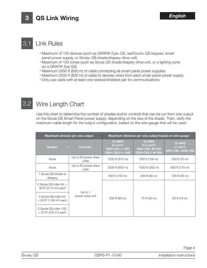
3.1 Link Rules
• Maximum of 100 devices (such as GRAFIK Eye® QS, seeTouch® QS keypad, smart
panel power supply, or Sivoia® QS shade/drapery drive unit)
• Maximum of 100 zones (such as Sivoia QS shade/drapery drive unit, or a lighting zone
on a GRAFIK Eye QS)
• Maximum 2000 ft (600 m) of cable connecting all smart panel power supplies
• Maximum 2000 ft (600 m) of cable to devices wired from each smart panel power supply
• Only use cable with at least one twisted/shielded pair for communications
3.2 Wire Length Chart
Use this chart to determine the number of shades and/or controls that can be run from one output
on the Sivoia QS Smart Panel power supply, depending on the size of the shade. Then, verify the
maximum cable length for the output confi guration, based on the wire gauge that will be used.
Maximum devices per one output Maximum distance per one output based on wire guage
Shades + Controls
12 AWG
(4 mm²)
QSH-CBL-L-500
QSH-CBLP-L-500
16 AWG
(1.5 mm²)
QSH-CBL-M-500
QSH-CBLP-M-500
18 AWG
(1 mm²)
GRX-CBL-346S-500
NoneUp to 50 power draw
units1250 ft (375 m) 500 ft (150 m) 250 ft (75 m)
NoneUp to 25 power draw
units2000 ft (600 m) 1000 ft (300 m) 600 ft (175 m)
1 Sivoia QS shade or
drapery
Up to 1
power draw unit
500 ft (150 m) 200 ft (60 m) 125 ft (35 m)
2 Sivoia QS roller 64, ≤
30 ft2 (2.75 m2) each
200 ft (60 m) 75 ft (20 m) 50 ft (15 m)3 Sivoia QS roller 64,
≤ 20 ft2 (1.80 m2) each
2 Sivoia QS roller 100,
≤ 50 ft2 (4.6 m2) each
English

Page 5
Sivoia® QS QSPS-P1-10-60 Installation instructions
3 QS Link Wiring (continued)
3.3 Example: Multiple shades per output
Sivoia QS roller 64, 25 sq ft (2.25 m2)
Sivoia QS roller 64, 25 sq ft (2.25 m2)
Up to 50 ft (15 m) of
18 AWG (1 mm2)
4-conductor twisted/
shielded wire
Close
Preset
Open Meeting
Videoconf
Afternoon
A/V Night
OffLUTRON
Close
Open
Preset
seeTouch® QSGRAFIK Eye® QS
Up to 250 ft (75 m) of
18 AWG (1 mm2)
4-conductor twisted/
shielded wire
English

Page 6
Sivoia® QS QSPS-P1-10-60 Installation instructions
QS Link Wiring (continued)3
3.4 Example: One shade per output
Up to 250 ft (75 m) of
18 AWG (1 mm2)
4-conductor twisted/
shielded wire
GRAFIK Eye® QS
Close
Preset
Open Meeting
Videoconf
Afternoon
A/V Night
Off
Sivoia QS roller 64, 25 sq ft (2.25 m2)
Sivoia QS roller 64, 25 sq ft (2.25 m2)
Up to 100 ft (30 m) of
18 AWG (1 mm2)
4-conductor
twisted/shielded wire
LUTRON
Close
Open
Preset
seeTouch® QS
Up to 100 ft (30 m) of
18 AWG (1 mm2)
4-conductor twisted/
shielded wire
English

1
1.1
Page 7
Sivoia® QS QSPS-P1-10-60 Installation instructions
4
4.1
Wiring the QSPS-P1-10-60
Run low voltage wire into the QSPS-P1-60
Remove as many knockout
tabs as necessary from the
left side of the enclosure and
insert strain reliefs.
Run the low-voltage
communication wiring from
the Lutron QS shade and
lighting devices through
the strain reliefs to the
terminal blocks.
Strip insulation wire so that
0.25 in (7 mm) of bare wire
is exposed. Make sure to
tighten the screws tightly
and that no insulation is
inside of the terminal block.
Input power from distribution panel
Hot (Live)
Neutral
Earth Ground
Low voltage wiring
(To Lutron shade and
lighting components)
English
1
1.1
Page 8
Sivoia® QS QSPS-P1-10-60 Installation instructions
4
4.2
Wiring the QSPS-P1-10-60 (continued)
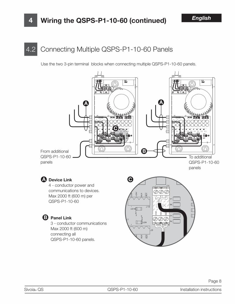
Connecting Multiple QSPS-P1-10-60 Panels
Use the two 3-pin terminal blocks when connecting multiple QSPS-P1-10-60 panels.
From additional
QSPS-P1-10-60
panels
To additional
QSPS-P1-10-60
panels
Device Link
4 - conductor power and
communications to devices.
Max 2000 ft (600 m) per
QSPS-P1-10-60
Panel Link
3 - conductor communications
Max 2000 ft (600 m)
connecting all
QSPS-P1-10-60 panels.
English

Page 9
Sivoia® QS QSPS-P1-10-60 Installation instructions
5
5.1
DiagnosticsThe QSPS-P1-10-60 provides built-in diagnostics to help
troubleshoot and verify your installation.
Output status LEDs
Each output has a status LED to indicate if the output is properly powered. If an
output becomes overloaded, its status LED will blink to indicate the fault condition.
Press the “Power Supply Clear” button after the fault condition has been cleared
and the LED will stop blinking.
Output status LEDs
2
3
4
LED
FUSE 5X20FUSE 5X20 10 9 8 7 6 5 4 3 2 1 10 9 8 7 6 5 4 3 2 1
1 2 3 4 5 6 7 8 9 10
1
2
3
4
5
6
7
8
9
10
FU
SE
5X20
CO
M
MU
X
MU
X
CO
M
MU
X
MU
X
LINK
If an output status LED has turned off, the fuse
will need to be replaced. The QSPS-P1-10-60
comes with two spare 5x20 mm 2.5 A fuses.
Fuses
5 6
FU
SE
5X20
Spare fuses
FUSE 5X20FUSE 5X20
English

Page 10
Sivoia® QS QSPS-P1-10-60 Installation instructions
5
5.2
Diagnostics (continued)
Communications Link LEDs
The QSPS-P1-10-60 has four diagnostic LEDs for the communications link.
Diagnostic LEDs
Reserved for future use
Reserved for future use
Link Traffi c
This LED will blink green to
indicate that devices are
communicating.
Status LED
This LED indicates that the
panel is operating properly.
If this LED is off, check
your wiring.
English
Page 11
Sivoia® QS QSPS-P1-10-60 Installation instructions
5
5.3
Diagnostics (continued)
Verify Communications
To verify the communications of your system, tap, hold (5 seconds), tap, hold
(5 seconds) the All Shades Open button. The QSPS-P1-10-60 is now trying to
communicate with all other devices. All EDUs communicating on the link will wiggle
and fl ash their green LED quickly. If you discover any EDUs that are not wiggling,
verify that the EDU is powered and wired properly. Link Diagnostics Mode will
automatically time out after 10 minutes.
To exit Link Diagnostics Mode, press and hold the All Shades Open button for
5 seconds.
English

Page 12
Sivoia® QS QSPS-P1-10-60 Installation instructions
SCOPE
This limited warranty (“Warranty”) covers the
Lutron supplied (a) Sivoia® QS Shade System
(“Sivoia® QS Shade System”), (b) Sivoia QEDTM
Shade System (“Sivoia QEDTM Shade System”),
(c) manual shade system and (d) alternating cur-
rent or a/c shade system (each of the foregoing
being a “System”). Customer acknowledges and
agrees that use of the System constitutes accep-
tance of all terms and conditions of this Warranty.
LIMITED WARRANTY
Subject to the exclusions and restrictions de-
scribed below, Lutron warrants that each System
will be free from manufacturing defects from the
date of shipment by Lutron for a period of (a)
one year as to the wall controls, interfaces and
system accessories of the Sivoia® QS Shade
System (“External Sivoia® QS Components”)
and (b) eight years as to the other Systems and
the electronic drive unit, shade fabric and shade
hardware of the Sivoia® QS Shade System. If
any manufacturing defect exists in the External
Sivoia® QS Components, so long as Customer
promptly notifi es Lutron of the defect within the
one year warranty period and, if requested by
Lutron, returns the defective part(s), Lutron will,
at its option, either repair the defective part(s)
or provide comparable replacement part(s). If
any manufacturing defect exists in any of the
components of a System other than the External
Sivoia® QS Components, so long as Customer
promptly notifi es Lutron of the defect within the
eight year warranty period and, if requested by
Lutron, returns the defective part(s), Lutron will,
at its option, either repair the defective part(s)
or issue a credit to the Customer against the pur-
chase price of comparable replacement part(s)
purchased from Lutron as provided below:
Replacement parts for the System provided by
Lutron or, at its sole discretion, an approved ven-
dor may be new, used, repaired, reconditioned,
and/or made by a different manufacturer.
EXCLUSIONS AND RESTRICTIONS
This Warranty will be void, and Lutron and its
suppliers will have no responsibility under this
Warranty, if Lutron or its representatives can-
not access any components of the System to
inspect, diagnose problems with or repair the
System or any of its components as a result of
concealment or inaccessibility of such compo-
nents within a building structure.
This Warranty does not cover, and Lutron and its
suppliers are not responsible for:
1. Damage, malfunction or inoperability diag-
nosed by Lutron or a Lutron approved third
party as caused by normal wear and tear,
abuse, misuse, incorrect installation, neglect,
accident, interference or environmental fac-
tors, such as (a) use of incorrect line voltages
fuses or circuit breakers; (b) failure to install,
maintain and operate the System pursuant to
the operating instructions provided by Lutron
and the applicable provisions of the National
Electrical Code and of the Safety Standards of
Underwriter’s Laboratories; (c) use of incom-
patible devices or accessories; (d) improper or
insuffi cient ventilation; (e) unauthorized repairs
or adjustments or alterations; (f) vandalism; (g)
an act of God, such as fi re, lightning, fl ood-
ing, tornado, earthquake, hurricane or other
problems beyond Lutron’s control; or (h) direct
exposure to corrosive materials.
2. On-site labor costs to diagnose issues with,
and remove, repair, replace, adjust, reinstall
and/or reprogram the System or any of its
components.
3. Components and equipment external to the
System, such as, non-Lutron lighting and
automation systems; building wiring audio-vi-
sual equipment; and non-Lutron time clocks,
photosensors and motion detectors.
4. The cost of repairing or replacing other prop-
erty that is damaged when any System does
not work properly, even if the damage was
caused by the System.
Limited Warranty
Number of years
from date
of shipment
Percentage of cost of
replacement parts
credited by Lutron
Up to 5 100%
More than 5 but
not more than 850%
More than 8 0%
English

Page 13
Sivoia® QS QSPS-P1-10-60 Installation instructions
THIS WARRANTY IS IN LIEU OF ALL OTHER
EXPRESS WARRANTIES. ALL IMPLIED
WARRANTIES, INCLUDING THE IMPLIED
WARRANTIES OF MERCHANTABILITY AND
OF FITNESS FOR A PARTICULAR PUR-
POSE, ARE LIMITED TO EIGHT YEARS
FROM THE DATE OF SHIPMENT, EXCEPT
THAT SUCH IMPLIED WARRANTIES ARE
LIMITED TO ONE YEAR FROM THE DATE
OF SHIPMENT AS TO THE EXTERNAL
Sivoia QS COMPONENTS.
NO LUTRON AGENT, EMPLOYEE OR REP-
RESENTATIVE HAS ANY AUTHORITY TO
BIND LUTRON TO ANY AFFIRMATION, REP-
RESENTATION OR WARRANTY CONCERN-
ING THE SYSTEMS. UNLESS AN AFFIRMA-
TION, REPRESENTATION OR WARRANTY
MADE BY AN AGENT, EMPLOYEE OR REP-
RESENTATIVE IS SPECIFICALLY INCLUDED
HEREIN, OR IN STANDARD PRINTED MA-
TERIALS PROVIDED BY LUTRON, IT DOES
NOT FORM A PART OF THE BASIS OF ANY
BARGAIN BETWEEN LUTRON AND CUS-
TOMER AND WILL NOT IN ANY WAY BE
ENFORCEABLE BY CUSTOMER.
IN NO EVENT WILL LUTRON OR ANY OTH-
ER PARTY BE LIABLE FOR EXEMPLARY,
CONSEQUENTIAL, INCIDENTAL OR SPE-
CIAL DAMAGES (INCLUDING, BUT NOT
LIMITED TO DAMAGES FOR PERSONAL
INJURY, FAILURE TO MEET ANY DUTY,
INCLUDING OF GOOD FAITH OR REASON-
ABLE CARE, NEGLIGENCE, OR ANY OTHER
LOSS WHATSOEVER), NOR FOR ANY RE-
PAIR WORK UNDERTAKEN WITHOUT LU-
TRON’S PRIOR WRITTEN CONSENT ARIS-
ING OUT OF OR IN ANY WAY RELATED TO
THE INSTALLATION, DEINSTALLATION, USE
OF OR INABILITY TO USE THE SYSTEM
OR OTHERWISE UNDER OR IN CONNEC-
TION WITH ANY PROVISION OF THIS WAR-
RANTY, EVEN IN THE EVENT OF THE FAULT,
TORT (INCLUDING NEGLIGENCE), STRICT
LIABILITY, BREACH OF CONTRACT OR
BREACH OF WARRANTY OF LUTRON OR
ANY OTHER PARTY, AND EVEN IF LUTRON
OR SUCH OTHER PARTY WAS ADVISED OF
THE POSSIBILITY OF SUCH DAMAGES.
NOTWITHSTANDING ANY DAMAGES THAT
CUSTOMER MIGHT INCUR FOR ANY REA-
SON WHATSOEVER (INCLUDING, WITHOUT
LIMITATION, ALL DIRECT DAMAGES AND
ALL DAMAGES LISTED ABOVE), THE EN-
TIRE LIABILITY OF LUTRON AND OF ALL
OTHER PARTIES UNDER THIS WARRANTY
ON ANY CLAIM FOR DAMAGES ARISING
OUT OF OR IN CONNECTION WITH THE
MANUFACTURE, SALE, INSTALLATION, DE-
LIVERY, USE, REPAIR, OR REPLACEMENT
OF THE SYSTEM, AND CUSTOMER’S SOLE
REMEDY FOR THE FOREGOING, WILL BE
LIMITED TO THE AMOUNT PAID BY CUS-
TOMER FOR THE SYSTEM. THE FOREGO-
ING LIMITATIONS, EXCLUSIONS AND DIS-
CLAIMERS WILL APPLY TO THE MAXIMUM
EXTENT ALLOWED BY APPLICABLE LAW,
EVEN IF ANY REMEDY FAILS ITS ESSEN-
TIAL PURPOSE.
THIS WARRANTY GIVES YOU SPECIFIC
LEGAL RIGHTS. YOU MAY ALSO HAVE
OTHER RIGHTS WHICH VARY FROM STATE
TO STATE. SOME STATES DO NOT ALLOW
LIMITATIONS ON HOW LONG AN IMPLIED
WARRANTY LASTS OR THE EXCLUSION
OR LIMITATION OF INCIDENTAL OR CON-
SEQUENTIAL DAMAGES, SO THE ABOVE
LIMITATIONS OR EXCLUSIONS MAY NOT
APPLY TO YOU.
WARRANTY CLAIMS, TECHNICAL ASSIS-
TANCE AND WARRANTY INFORMATION.
Contact the Lutron Technical Support Center at
the numbers provided below or your local Lutron
sales representative with questions concerning
the installation or operation of the System or this
Warranty, or to make a warranty claim. Please
provide the exact model number when calling.
Lutron, the Sunburst logo, and Sivoia are
registered trademarks, and Sivoia QS is a
trademark of Lutron Electronics Co., Inc.
English

Page 14
Sivoia® QS QSPS-P1-10-60 Installation instructions
Technical Assistance
WORLD
HEADQUARTERS
Lutron Electronics Co., Inc.
7200 Suter Road
Coopersburg, PA 18036
United States
Tel: +1.610.282.3800
Fax:+1.610.282.1243
ASIAN
HEADQUARTERS
Lutron GL Ltd.
15 Hoe Chiang Road
#07-03 Tower Fifteen
Singapore 089316
Tel: +65.6220.4666
Fax: +65.6220.4333
EUROPEAN
HEADQUARTERS
Lutron EA Ltd.
6 Sovereign Close
London, E1W 3JF
United Kingdom
Tel: +44.(0)20.7702.0657
Fax: +44.(0)20.7480.6899
CUSTOMER SERVICE/
ORDERING
UK +44.(0)20.7702.0657 –
09.00 - 18.00 GMT
USA +1.610.282.-3800 –
08.00 - 20.00 EST
CUSTOMER SERVICE
TECHNICAL SUPPORT
& SERVICES
USA +1.610.282.3800 –
24 hours/7 days
UK +44.(0)20.7702.0657
09.00 - 18.00 GMT
INTERNET:
www.lutron.com
ADDITIONAL LUTRON
SALES OFFICES:
Germany
Tel: +49.309.710.4590
Fax: +49.309.710.4591
FREEPHONE
00800.5887.6635
France
Lutron Ltc, S.A.R.L.-Paris
90 rue Villiers
92300 Levallois Perret,
France
Tel: +33.1.41.05.42.80
Fax: +33.1.41.05.01.80
FREEPHONE: 0800.90.12.18
Spain-Madrid
Tel: +34.91.567.84.79
Fax: +34.91.567.84.78
FREEPHONE 0900.948.944
Spain-Barcelona
Tel: +34.93.496.57.42
Fax: +34.93.496.57.50
FREEPHONE 0900.948.944
Hong Kong
Tel: +852.2104.7733
Fax: +852.2104.7633
Beijing
Tel: +86.10.5877.1817
Fax: +86.10.5877.1816
Singapore
LUTRON GL Ltd. -
Singapore
15 Hoe Chiang Road
#7-03 Tower 15
Singapore 089316
Tel: +65.6220.4666
Fax: +65.6220.4333
Japan
Tel: +81.3.5575.8411
Fax: +81.3.5575.8420
www.lutron.com/shadingsolutions
USA and Canada (24 hrs/7days):
call: 800.523.9466
Other countries (8 a.m. – 8 p.m. ET)
call: +1.610.282.3800
fax: +1.610.282.3090
email: [email protected]
©2012 LUTRON Electronics Co., Inc.
Printed in the U.S.A.
P/N 045-310 REV B
English


![Larbert High School Faculty of Mathematics24453]Higher_Past...2009 P1 Q15 2009 P1 Q21 2010 P1 Q1 2010 P1 Q8 2010 P1 Q21 2010 P1 Q23 2011 P1 Q2 2011 P1 Q8 2011 P1 Q21 2012 P1 Q4 2012](https://img.pdfslide.net/doc/110x75/60bd9bf2b65aaa2b316d3bc9/larbert-high-school-faculty-of-mathematics-24453higherpast-2009-p1-q15-2009.jpg)