Embed Size (px)
Citation preview

1
PrinterNOx Operating Manual – English
Gebrauchsanweisung - Deutsch


1
Contents
I. Important safety information – English ................................ 3
Introduction ..................................................................... 4
Medical Use ...................................................................... 5
NO2 Production ................................................................. 6
Environmental Safety ........................................................ 6
Operation......................................................................... 7
1. Measurement ............................................................10
2. Calibration ................................................................17
3. Set Alarms................................................................23
4. Report to printer........................................................24
5. Status ......................................................................24
6. Setup .......................................................................25
7. Calculate Flow ...........................................................26
Battery operation.............................................................27
Paper Loading..................................................................28
Battery Maintenance.........................................................29
Cleaning Procedure...........................................................31
Servicing.........................................................................31
Symbols..........................................................................32
Electrical Environment ......................................................32
Specifications ..................................................................32
II. Wichtige Sicherheitshinweise – Deutsch ..............................36
Einleitung........................................................................37
Medizinische Anwendung...................................................38
NO2 Produktion ................................................................39
Umweltschutz ..................................................................40
Betrieb............................................................................40
1. Messung ...................................................................44
2. Kalibration ................................................................52
3. Alarmeinstellungen ....................................................58
4. Bericht an den Drucker...............................................59

2
5. Status ......................................................................59
6. Setup .......................................................................60
7. Durchfluss berechnen.................................................61
Batteriebetrieb ................................................................62
Papier einlegen ................................................................63
Batterie wartung ..............................................................64
Reinigung........................................................................66
Wartung..........................................................................67
Symbole .........................................................................67
Elektrische Umgebung ......................................................68
Technische Daten.............................................................68
Customer Contact Information ...........................................70

3
PrinterNOx Operating manual
I. Important safety information - English
Nitric oxide is a highly toxic gas, exposure to levels as low as 200
parts per million (ppm) may be fatal even after very short
exposures, and prolonged exposure to much lower levels may be
harmful. All users of nitric oxide must familiarise themselves with
the appropriate safety regulations. When calibrating the PrinterNOx
monitor it is important to ensure that calibration gas is adequately
vented and safely exhausted. Nitric oxide reacts with oxygen in air
to form nitrogen dioxide, an extremely toxic gas with a maximum
allowable industrial ambient level of 5ppm.
The PrinterNOx nitric oxide/nitrogen dioxide monitor has been
designed to the highest standards and incorporates many inbuilt
self-checks. As with any measurement device, however,
malfunction is possible. When used in the administration of nitric
oxide the PrinterNOx must not, therefore, be incorporated as a
primary part of the NO delivery system, but rather as a safety check
on the delivery system. The delivery system should be constructed
in such a way as to minimise possible errors. CareFusion Ltd does
not accept any liability for injury resulting from malfunction and
failure to follow these guidelines. Failure to follow instructions in the
remainder of this manual may also result in dangerously inaccurate
measurements being obtained.

4
Introduction
The PrinterNOx is a combined Nitric Oxide / Nitrogen Dioxide
monitor based on electrochemical fuel cells and may be operated
directly from the mains power or from the internal rechargeable
NiCad battery pack. Fuel cells work through the reaction of the
target gas with an electrolyte at one electrode and oxygen (from
ambient air) at the other. This reaction generates an electrical
current proportional to gas concentration. In comparison with other
technologies (such as chemiluminescent detectors) electrochemical
sensors are compact, inexpensive and much easier to use with zero
warm up time and simple calibration. The PrinterNOx is designed to
monitor delivered NO used as a therapy for adult respiratory distress
syndrome and pulmonary hypertension on ventilated patients. The
more toxic and non therapeutic by-product, NO2, is also monitored.
The NO measurement has a resolution of 0.05 parts per million
(ppm) with a full scale of 100ppm and the NO2 measurement has a
resolution of 0.05ppm with a full scale of 20ppm. The gas to be
monitored is sampled using a constant flow (250ml/min), low dead
space, sidestream system. The system includes a water trap, with
integral hydrophobic filter, and humidity conditioning circuit to
protect the fuel cells against extremes of humidity and particulate
contamination. The measurements are displayed on a large graphic
liquid crystal display and can be printed as a chart, on the integral
thermal printer, together with calibration due date and alarm
settings. The last 24 hours of NO and NO2 measurements taken are
recorded and stored in the internal battery backed memory and can
be printed or uploaded on the RS232 interface for computer storage.
The PrinterNOx includes a number of safety features and alarms.
These include upper and lower alarms for NO and an upper alarm for
NO2. An external alarm cable is available, and when connected to a
NO delivery system, is used to trigger an alarm or initiate a safe
operating mode if high concentrations of gas are detected. This
concentration is 100ppm for NO, 9ppm NO2 or alarm level whichever

5
is the greater. The flow of gas in the sampling line is continuously
monitored and an alarm sounded if the line is occluded or the water
trap is full. A low battery condition is also alarmed.
The PrinterNOx has been designed with ease of use and reliability as
of foremost importance. To ensure accurate results, however, it is
essential to familiarise yourself with the contents of this short
manual.
Medical Use
Nitric oxide (NO) is evolving as a novel therapy used to reduce
pulmonary arterial pressure and improve gas exchange in paediatric
and adult intensive care settings. The NO is usually added to the
ventilator circuit from a cylinder of NO in nitrogen with a
concentration up to 1000ppm and diluted in the circuit to between 1
and 40ppm.
Therapeutic concentrations must be well controlled as levels as low
as 100ppm may cause lung injury.
For safety reasons sources with greater than 1000ppm NO should
not be used. Lower concentrations carry less risk either to the
patient in the case of accidental overdose, or to the hospital staff in
the case of leakage. However, if moderately high doses of NO are to
be administered then the decrease in the maximum FiO2 must be
considered and is given by the relationship:
FiO2 (max.) = (1 - Required NO Conc./Source NO Conc.) X
100%
Therefore, if 40ppm is required from a source of 500ppm NO in
nitrogen then the maximum oxygen available would be:
FiO2 (max.) = (1 - 40 / 500) X 100% = 92%

6
Methods for therapeutic administration of nitric oxide depend on the
exact type of ventilator and ventilator circuit to be used and have
not yet been standardised. It is therefore the responsibility of the
user to pay due regard to current medical practice when using the
unit to monitor concentrations of inhaled nitric oxide and nitrogen
dioxide.
NO2 Production
Nitric oxide in the presence of oxygen undergoes the following
chemical reaction to form nitrogen dioxide, (a more toxic gas than
nitric oxide):
2NO + O2 →→→→ 2NO2
The rate of conversion is highly dependent on the NO concentration
and this has some important implications for the NO delivery
system.
Firstly, sources of NO with excessively high concentrations should be
avoided.
Secondly, the administered concentration should be kept as low as is
clinically acceptable.
Finally, the administration system should mix the incoming NO
quickly and effectively to rapidly reduce its concentration to the
therapeutic level where NO2 production will proceed at a much
slower rate.
Environmental Safety
To eliminate environmental pollution with NO and NO2 the
PrinterNOx is supplied with two NOxSORB chemical scavengers for
removing these gases from the exhaust. The NOxSORB works by
converting NO to NO2, which is then chemically absorbed.

7
Connect a NOxSORB to the exhaust of the PrinterNOx, as shown
overleaf, orientated such that the arrow is pointing away from the
instrument. The NOxSORB should be replaced after 24 hours or
when the mauve spheres turn dark brown. When re-ordering please
quote 36-SORB100 for a box of 10 of 36-SORB200 for a box of 20.
Environmental pollution with NO and NO2 may also arise when leaks
are present in the connections to the source of NO.
Operation
Before operating the PrinterNOx, ensure that the unit has been fully
charged using the AC adapter supplied. (See Charging Procedure.)
The PrinterNOx may also be operated with the internal rechargeable
batteries.
Connect the water trap with integral hydrophobic PTFE filter and
sampling line to the PrinterNOx as shown below:
SamplingLine
WaterTrap
MicroMedical
Water trapretainingscrews
Exhaustport
1
Alarm
PAPER
6
42 3 5
97
C AN C EL
8
CH AR G IN G
0
EN T ER
PrinterNOx
NOxSORB
Switch on the PrinterNOx. Please note that the water trap must
be used at all times during measurement to avoid
contamination of the fuel cells.

8
The on/off switch is located at the rear of the unit:
An introductory screen giving the software version will be displayed
briefly:
MICRO MEDICAL
PrinterNOx
V X.XX
During this time the following information will be printed:
12/04/95 16:14NO calibration due : 01/01/96NO2 calibration due : 07/01/96NO upper alarm : 15NO lower alarm : 5NO2 upper alarm : 4
AC Adapter socket
500mA Power Input
Contrast
Display contrastadjustment
O 12V 1
On/Off switch
RS232/ Analogue Output
RS232socket
External Alarm
External alarmsocket
9
This information can be checked and the date, time, calibration or
alarm settings may be adjusted prior to performing a measurement.
(See sections on Setup, Calibration, and Set Alarms)
The calibration due date is set to occur thirty days after the last
calibration. However, calibration may be performed at any time
before this date to improve measurement accuracy. Measurements
can be made after the calibration due date has passed but
consideration must be given to the gas sensors which exhibit a slow
decline in sensitivity over time. This loss of sensitivity is typically
less than 2% per month but could be more if they are exposed to
adverse conditions such as exposure to gas concentrations above
the measurement range or to solvents such as alcohol.
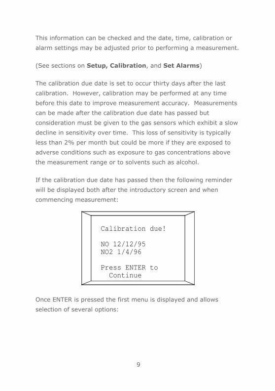
If the calibration due date has passed then the following reminder
will be displayed both after the introductory screen and when
commencing measurement:
Calibration due!
NO 12/12/95 NO2 1/4/96
Press ENTER to Continue
Once ENTER is pressed the first menu is displayed and allows
selection of several options:

10
Select Option1 Measurement2 Calibration3 Set Alarms4 Report to printer5 Status6 Setup7 Calculate Flow
Whilst this display is active the sampling pump is turned off,
measurements are not taken, and the gas level alarms are inactive.
If no options are selected then the unit defaults to option 1
“Measurement” after 45 seconds. This is done so that the unit
defaults to monitoring gas levels with alarms activated in the event
that the instrument was inadvertently left on the first screen or was
switched off and on.
During all other operations, a short warning alarm will occur, after
45 seconds of inactivity, to remind the user that measurement mode
is not operational.
1. Measurement
To obtain maximum accuracy from the measurement careful
consideration must be given to the NO administration system in use.
Gas measurement with ventilators producing cyclic flows may give
an overestimate or under estimate of the average NO concentration.
This is due to localised variation of NO concentration within the
delivery system. Dependent on the measurement point, therefore,
the sampled average may not correspond to the delivered average.
It is therefore important to ensure that the NO delivery system is
designed to avoid large variations in the level of delivered NO.

11
The PrinterNOx utilises a sidestream gas system, which is servo
controlled to sample at a constant rate of 250 ml/min. By supplying
the gas sensors with this constant flow, a high degree of accuracy
and sensitivity can be achieved.
To carry out NO / NO2 measurement, press “1”.
The sampling pump will start and the following screen will be
displayed:
15 5 p p 4 m
Press ENTER for menu
NO
NO
0000002
.
.
The system should now be tested for leaks by occluding the
sampling line. The pump will be heard to rise in pitch as the servo
system tries to overcome the restriction.
As the pump cannot maintain the required flow rate then the
measurement will cease to be displayed, the pump will continue to
run, and the following message will be displayed:
Gas Line Occluded or water trap full Please clear blockage or empty water trap and filter.

12
When the occlusion is removed, the display will automatically revert
to the measurement screen. Repeat this procedure by occluding the
exhaust port.
The sampling line should now be connected to the administered gas,
normally as close to the patient as possible. The sampling port must
be positioned in such a way that water cannot enter the tubing,
causing rapid filling of the water trap.
If the gas line appears to be continuously occluded, remove the
water trap and empty any water into a suitable container. Ensure
that there is no occlusion on the exhaust port.
Under exceptional circumstances, water may pass through a
damaged water trap and obstruct the inlet to the PrinterNOx. In this
case turn the unit off and draw any liquid out of the inlet with a
syringe connected directly to the inlet. Replace the water trap with
a new one, turn the unit on, and return to the measurement screen.
On the left-hand side of the NO legend are the upper and lower
alarm levels for NO. On the left-hand side of the NO2 legend is the
upper alarm level for NO2.
On the bottom line, the rectangle will blink on or off every time a
measurement is updated (every 2.6 seconds) to indicate correct
functioning of the instrument.
The gas concentrations are given in parts per million (ppm).
If the printer option is turned on (see Setup section), then the
following printout will be obtained during measurement:

13
12/04/95 16:14NO calibration due : 01/01/96NO2 calibration due : 07/01/96NO upper alarm : 15NO lower alarm : 5NO2 upper alarm : 4
Patient :...............................
Hospital :...............................
Technician :...............................
5 NO 15 0 NO2 4
1715
1730
Spaces for entering the patient name or ID, hospital name, and
technician name are provided.
This is followed by the axes for the NO and NO2 graphs.
These graphs are auto scaled to the current alarm settings.
A section of the graph will be printed once every 32 samples and
includes a time stamp every 15 minutes on the left-hand side. Each
dot on the graph represents the average of 4 measurements.

14
If the measured gas goes outside the range of the alarm settings
then an audible alarm and a red flashing visual alarm will be
generated. In addition, the relevant indicator on the liquid crystal
display will flash. The graph is then replaced by a printout of each
individual measurement together with a time stamp and an alarm
indicator as shown below:
12/04/95 16:14NO calibration due : 01/01/96NO2 calibration due : 07/01/96NO upper alarm : 15NO lower alarm : 5NO2 upper alarm : 4
Patient :...............................
Hospital :...............................
Technician :...............................
5 NO 15 0 NO2 4
1715
1730
1741 Alarm NO = 22.3 NO2 = 1.851741 Alarm NO = 22.4 NO2 = 1.951741 Alarm NO = 23.1 NO2 = 2.101742 Alarm NO = 23.0 NO2 = 1.90
If the NO measurement exceeds 100ppm or NO2 exceeds 9ppm then
the external alarm, accessible at the rear of the instrument, is

15
activated. If the NO2 alarm level is set above 9ppm, then the
external alarm comes into operation at the set level for NO2. The
external alarm consists of a pair of normally closed contacts, which
are latched open when the above condition occurs. This can be used
to sound an external alarm or switch a NO delivery system into safe
operating mode in systems equipped with this facility.
The display will change to:
.
15 5 p p 4 m
CUT OUT: PRESS ENTER
987148NO
NO2
.
Measurements will continue but it should be noted that the
measurement range would be limited to just over 100ppm NO and
20ppm NO2 and that the actual concentrations could be significantly
higher.
Press enter to clear the external alarm when the reading drops
below the external alarm levels.
When this condition occurs, the cause should be immediately
investigated. However, caution should be observed when shutting
down the supply of NO, as the sudden cessation of NO can be more
detrimental to the patient than a temporary overdose of NO.
Ideally, the external alarm should be used to switch the delivery
system into a ‘safe’ operating mode or switch in a backup supply.

16
Syringeadapter
15
5
10
20
Should the water trap fill during the course of the measurement, it
will overflow into the integral hydrophobic PTFE filter, cause an
obstruction, and the following message will be displayed:
Gas Line Occluded or water trap full Please clear blockage or empty water trap and filter.
Unscrew the two retaining screws, and remove the water trap from
the PrinterNOx.
Empty the accumulated water into a suitable container by
connecting a syringe (20ml minimum size) with the adapter supplied
and pushing air through the assembly as shown below.

17
Reconnect water trap to the PrinterNOx and secure with the two
retaining screws. If the ‘Gas Line Occluded’ message reappears,
disassemble and replace the water trap with a new one.
Under exceptional circumstances, water may pass through a
damaged water trap and obstruct the inlet to the PrinterNOx. In this
case turn the unit off and draw any liquid out of the inlet with a
syringe connected directly to the inlet. Replace the water trap with
a new one, turn the unit on, and return to the measurement screen.
The alarm may be muted for a 45-second period by pressing the
CANCEL key.
2. Calibration
If the instrument is in use immediately before calibration is
attempted, then the system should be purged with clean air. This
may be done by disconnecting the water trap from the instrument
and running the instrument in measurement mode for 5 minutes.
To carry out sensor calibration press 2 and the following screen will
be displayed:
Disconnect instrument from gas sources. Press ENTER to startPress CANCEL to abort
The PrinterNOx requires clean air free from any NO or NO2 so that
the sensors can be zeroed.

18
With the water trap disconnected, press enter and the display will
change to:
Zeroing *..............
Press CANCEL to abort
The sampling pump will start and the PrinterNOx will monitor the
output of both sensors until a stable reading is obtained.
During this time, a line of asterisks appears on the screen to indicate
correct operation.
When zeroing is complete the readings for the NO and NO2 sensors
are written into the battery backed memory and the display is
changed to:
Calibration ----------- 1 Calibrate NO 2 Calibrate NO2 3 Exit

19
Press “1” to calibrate NO and the display will change to:
Enter NO calibrationgas concentration:
00.0 ppm
Enter the required gas concentration using the DELETE key to
correct any mistakes and press ENTER.
The display will change to:
Pass calibration gas through instrument
Press ENTER to startPress CANCEL to abort
CareFusion can supply calibration gas (25ppm NO in nitrogen and
10ppm NO2 in air) complete with a control valve for simple and
economic user calibration.
The gas is supplied in convenient, disposable, aluminium canisters
containing 58 litres of gas (Cat No 36-GAS100 for 25ppm NO in
nitrogen and 36-GAS200 for 10ppm NO2 in air). A flow regulator
pre-set to deliver 500ml/min is available separately, Cat No 36-
GAS500. With careful use, approximately 45 calibrations can be
obtained from each canister.

20
Screw the control valve on to the canister and connect to the
PrinterNOx with the water trap connected as shown below:
Slowly turn the control knob fully anti-clockwise. This will then
supply a flow of approximately 500ml/min. As the PrinterNOx
samples at a rate of 250ml/min then 250ml/min will be vented
through the one way valve.
MicroMedical
Pressure Guage
25 ppmNitric Oxidein Nitrogen
OR 10 ppmNitrogen Dioxidein air
One Way Relief Valve
ControlValve
Pre-setFlow Regulator(500ml/min)
USE NO OIL 0
psi 1000
4 9
Alarm 2 1 3 7
CANCEL PAPER 6 8
CHARGIN G
5 0
ENTER
PrinterNOx

21
Press ENTER on the keypad and the display will change to:
Calibrating NO
*.............
Press CANCEL to abort
The sampling pump will start and the PrinterNOx will monitor the
output of the NO sensor until a stable reading is obtained. When
stability has been achieved the calibration factor, time and date are
written into the battery backed memory and the display returns to
the previous screen. Remove the control valve by turning anti-
clockwise to stop the gas flow. The NO2 sensor can now be
calibrated using the same procedure if required.
Within the lifetime of the sensors, zero drift of more than 10ppm
(1ppm for NO2) or a calibration drift of more than 40% implies
abnormal ageing of the electrochemical cell. If these errors are
detected during the zeroing procedure or the calibration adjustment
then the following will be displayed:
------- ERROR -------Reading out of range:Check gas supply and try again. Refer to manual if error recurs.
Press any key

22
The most likely reason for this message is an operational error in the
calibration procedure rather than a faulty sensor.
If this occurs during zeroing repeat the procedure and check that
there is no nitric oxide, or nitrogen dioxide contamination, and that
the water trap has been removed.
If the calibration error message appears during sensitivity
adjustment, repeat the calibration procedure and check:
1. Is calibration gas within its warranty period?
2. Has correct gas concentration been entered?
3. Have the correct connections been made with no leaks?
4. Is there sufficient calibration gas flow?
5. Is there any reaction between nitric oxide and the connectors used?
6. Are there any contaminants between nitric oxide supply and sensor?
Nitric oxide is a very reactive gas and it is difficult to maintain a
stable concentration within a cylinder. It is therefore advisable to
have some independent means of checking the calibration gas used.
After calibration is complete, selecting option “3 Exit” will return the
display to the main menu screen.

23
3. Set Alarms
Selecting option three will allow the NO and NO2 alarm levels to be
set individually from the following menu:
Set Alarms
1 Upper NO : 20 2 Lower NO : 5 3 Upper NO2 : 4 4 Exit
The current alarm levels are displayed for reference and, for
example, the upper alarm level for NO may be altered by selecting
option 1 when the following screen will be displayed:
Enter new alarm level :
Upper NO :
Type in the required alarm level and press ENTER.
The lower NO and NO2 alarm levels are set with the same procedure
with option 2 and 3 respectively.
The valid range of entry is 0 to 99 for the NO upper and lower
alarms and the upper alarm must be set higher than the lower
alarm.

24
For NO2, the valid range of entry is zero to 19
When the required alarms have been set, then selecting option 4 will
return to the main menu.
4. Report to printer (RS232)
The last 24 hours of measurements are stored in battery backed
memory and may be either printed or directed to the RS232 port at
the rear of the instrument. The choice of recovery method depends
upon whether the printer or RS232 port is currently active (see
Setup).
If the RS232 port is active then the data, in ASCII format, may be
uploaded to a PC running standard communication software. A
serial cable, Cat No 36-CAB1108, is available from CareFusion.
Note: Please ensure that all PC’s and peripheral equipment comply
to EN60950 ‘Safety of Information Technology Equipment’ and keep
them out of reach of the patient when connected to the PrinterNOx.
5. Status
This option allows the current configuration and sensor information
to be displayed.

25
6. Setup
Selecting this menu item allows various options to be set and
displays the screen:
SET UP 1 Clear memory 2 Set date/time 3 Toggle output: *printer RS232 4 Toggle date format *DD/MM MM/DD 5 Exit
The first option clears the stored 24 hours data from the memory.
This is done when the currently stored data is of no interest or has
previously been accessed so that future access of required data will
be quicker.
The second option is used to change the date and time stored in the
real time clock.
“Toggle output” is used to select whether data is sent to the printer
or the RS232 port at the rear of the instrument. An asterisk appears
against the selected output device. The initial few lines of
calibration and alarm information is always printed regardless
whether the printer is selected.
The date format can be changed using option 4.
Option 5 returns the display to the main menu screen.

26
7. Calculate Flow
This facility is used to calculate the required NO flow to achieve the
required therapeutic concentration for ventilators which employ a
constant bias flow arrangement. When selected the following screen
is displayed:
Enter ventilator bias flow:
L/min
The valid range for the bias flow is 1-99 and once entered the
display changes to:
Enter NO gas concentration in bottle:
ppm
Gas concentrations of between 50 and 1000ppm may be entered.

27
Following this, the required NO concentration in the range 1 to 100
should be entered:
Enter required NO gas concentration to patient:
ppm
When all the data is entered the required NO flow and the maximum
FiO2 is calculated and displayed on the following screen:
Bias flow 70 L/mBottle conc 650 ppmPatient conc 20 ppm
Req NO flow 2.22 L/mMaximum FiO2 96.9 %
Press key to continue
Battery operation
During patient transportation or mains power failure, the PrinterNOx
may be powered from the internal rechargeable batteries for
approximately 2 hours.

28
When the batteries are low the alarm will sound continuously and
the following screen will be displayed:
Battery low!
Please connect chargerand wait.
Paper Loading
The PrinterNOx requires thermal paper (Part Number 36-PSA1600 -
Pack of 5 rolls) for the printer.
A warning line appears when 30cm of the paper roll remains. A new
roll should be loaded when this mark becomes visible.
To load paper:
a. Switch on the PrinterNOx.
b. Cut the leading edge of the paper so that it is parallel to the
roll shaft.
c. Remove the paper cover.
d. Align the paper so that it is straight when it is inserted into
the paper inlet.
e. Press the “PAPER” key to feed the paper until the leading
edge of the paper passes the paper cutter.
f. Replace paper cover.

29
Make sure that the specified paper (Part Number 36-PSA1600) is
used as excessive wear on the thermal print head may occur if paper
from other manufacturers is used. The following precautions should
be observed when storing or handling the thermal paper rolls:
• Do allow the printer to run without paper loaded.
• Do not store paper rolls in places exposed to direct sunlight.
• Do not use pastes containing organic solvents such as
alcohol, esters or ketones.
• Do not allow the paper to be exposed to vinyl chloride.
• Do not use cellophane tape on the paper.
• Do not allow printer paper to be exposed to diazo copy
paper that has been processed.
Battery Maintenance
The PrinterNOx is powered from a 7.2volt 600mA-hr battery pack
located under the paper cover or from the AC adapter supplied.
The battery pack is fully discharged when shipped from the factory.
Note: Ensure that the dc plug is inserted before the mains supply is
connected to the unit and that the main is switched off before
removing the plug.
Please re-charge the pack with the AC adapter supplied before use.
The battery pack will exhibit a slow decrease in capacity at a rate
dependant upon usage. If the PrinterNOx is normally powered from
the AC adapter then the battery pack will be on continuous trickle
charge. Under these conditions, the capacity will be greater than
60% of nominal capacity for a period of at least 5 years. If the
PrinterNOx is normally powered from the battery pack then the
capacity will be greater than 60% of nominal capacity for at least
1000 charge/discharge cycles. To obtain maximum life, the batteries

30
should be allowed to discharge until the battery low warning is
activated and then fully charged as in the following procedure.
a. Plug the adapter into the AC outlet and connect the cable to
the printer.
b. The Charging light at the front of the keypad will be
illuminated while the batteries are being charged.
c. The battery pack will take 16 hours to become fully charged.
d. Warning! Use only the AC adapter supplied. Use of any other
type may cause permanent damage to the PrinterNOx and
may cause a fire or electrical hazard.
Notes:
• Do not leave the PrinterNOx on with discharged batteries for
long periods since this may result in deterioration of the
batteries.
• The room temperature should be between 5 to 40 degrees C
during charging.
• The printer can be used immediately after the AC adapter is
connected, however, if the battery pack is not fully charged,
printing may stop temporarily until sufficient charge is
available.
• Do not short-circuit the battery pack.
• Batteries at the end of their service life should be returned to
CareFusion or an authorised representative for correct
disposal. These must only be replaced with the approved part
(CareFusion part No. 36-BAT1033)
• The PrinterNOx is CLASS I equipment (mains earth
connected).
• Warning! Do not puncture or incinerate the rechargeable
batteries.

31
The PrinterNOx also contains two primary lithium cells. One of these
cells is associated with the gas sensors conditioning circuit and is
replaced when the gas sensors expire in accordance with the service
manual. If the PrinterNOx is to remain unused for a period greater
than the service life of the gas sensors (18 months) then this
battery and the gas sensors must be removed in accordance with
the service manual. The other primary lithium cell is used for
memory backup purposes with a design life of at least 10 years and
must not be removed.
Cleaning Procedure
The water trap with integral filter and sampling line are for single
patient use only and must be discarded after use. The outside of the
PrinterNOx may be cleaned using a light rubbing action with a damp
cloth. The PrinterNOx must be removed from the mains supply
during cleaning and should be completely dry before re-connection.
Looking after your PrinterNOx
Please observe the following precautions:
• Do not keep the unit in a damp place or expose it to extremes
of temperature.
• Do not expose any part of the gas sampling system to any
solvents e.g. alcohol as these will damage the fuel cells.
Servicing
A full service manual including circuit diagrams and parts list is
available upon request. Servicing should only be carried out by
suitably trained personnel.

32
Symbols
Type B device
0086
In accordance with Directive 93/42/EEC
Disposal in compliance with WEEE
Electrical Environment
This instrument complies with directive EN60601-1-2
electromagnetic compatibility but can be affected by cellular phones
and by electromagnetic interference exceeding levels specified in
EN 50082-1:1992
In the event of interference it is advisable to remove the offending
equipment or increase the distance. Failure to do so may
compromise the safe operation of the PrinterNOx.
Specifications
Gases detected Nitric Oxide (NO)
Nitrogen Dioxide (NO2)
Sensor type Electrochemical fuel cells
Measurement ranges NO:
NO2:
100 Parts per million (ppm)
20ppm
Resolution NO:
NO2:
0.05ppm
0.05ppm

33
Accuracy NO:
NO2:
+/-5% or 0.05ppm whichever is the
greater.
+/-5% or 0.05ppm whichever is the
greater
Response time NO:
NO2:
Less than 10 seconds (90% FSD)
Less than 30 seconds (90% FSD)
Alarm range NO:
NO2:
lower and upper 0 to 99ppm
upper 0 to 19ppm
Safety cut-out NO:
operation NO2:
100ppm
9ppm
Alarmed conditions Water trap full
Sample line occluded.
Battery low
Sensor life >1 year
Sidestream flow rate 250 ml/minute
Input pressure range 0 to 100 cmH2O
Data storage 24 hours Printer type 320 dot / line, low power thermal
printer Paper type 11cm thermal paper Power supply (Class I Equipment)
Primary 100–250volt 50 - 60Hz
Secondary 12volt 1.5A DC
Battery pack Rechargeable NiCad 7.2V 600mA-
hours
Dimensions 315 x 120 x 90 mm
Weight 1.2 Kg
Operating temperature: 0 to +40 °C
Operating humidity: 30% to 90% RH
Internal battery life 10 years
Operating pressure: Atmospheric +/-10%
Storage temperature -20° to +70 °C
Storage humidity 30% to 90% RH


34
PrinterNOx Gebrauchsanweisung

35
Bildzeichen und Sicherheitshinweise in der
Gebrauchsanweisung
In Anlehnung an die ANSI-Empfehlungen (American National
Standards Institute) für Sicherheitshinweise wurden in dieser
Gebrauchsanweisung folgende Symbole verwendet:
Zusätzliche, in der Gebrauchanweisung abgebildete Symbole:

36
II. Wichtige Sicherheitshinweise - Deutsch
Stickstoffmonoxid ist ein extrem giftiges Gas. Selbst
eine kurze Exposition mit Werten unterhalb von 200
Teilen pro Million (ppm) kann fatale Folgen haben und
auch längere Aussetzungszeiten bei deutlich
niedrigeren Werten können gesundheitsgefährdend
sein. Alle Benutzer von Stickstoffmonoxid müssen sich
mit den entsprechenden Sicherheitsvorschriften
vertraut machen. Beim Kalibrieren des PrinterNOx
Monitors ist unbedingt zu gewährleisten, dass das
Kalibrationsgas korrekt freigesetzt und sicher
ausgeleitet wird. Stickstoffmonoxid reagiert mit dem in
der Luft vorhandenen Sauerstoff zu Stickstoffdioxid,
einem extrem giftigen Gas mit einem zulässigen Wert
in industrieller Umgebung von maximal 5 ppm.
Der Stickstoffmonoxid/Stickstoffdioxid PrinterNOx
Monitor wurde unter Beachtung der Wie bei allen
Messgeräten sind Fehlfunktionen jedoch möglich.
Daher darf bei Verabreichung von Stickstoffmonoxid
das PrinterNOx nicht als Primärelement des NO
Zufuhrsystems integriert, sondern eher als
Sicherheitskontrolle auf dem Zufuhrsystem eingebaut
werden. Das Zufuhrsystem muss so konstruiert sein,
dass mögliche Fehler minimiert werden.
CareFusion Ltd übernimmt keine Haftung für Schäden,
die sich aus einer Fehlfunktion und der Nichtbeachtung
dieser Richtlinien ergeben. Die Nichtbeachtung
der in dieser Anleitung gegebenen Anweisungen kann
darüber hinaus zu ungenauen und in der Folge
gesundheitsgefährdenden Messfehlern führen.

37
Einleitung
PrinterNOx ist ein kombinierter Stickstoffmonoxid/Stickstoffdioxid
Monitor, der elektrochemische Brennstoffzellen verwendet und direkt
am Stromnetz oder mit Hilfe des eingebauten aufladbaren NiCad
Batterieblocks betrieben werden kann. Das Prinzip der Brennstoffzellen
basiert auf der Reaktion des Zielgases auf ein an einer Elektrode
vorhandenes Elektrolyt und auf den Sauerstoff (aus der Raumluft) auf
der anderen Elektrode. Diese Reaktion erzeugt einen zur
Gaskonzentration proportionalen elektrischen Strom. Im Vergleich zu
anderen Methoden (wie z. B. chemoluminiszenten Detektoren) sind
elektrochemische Sensoren kompakt, preiswert und leichter zu
benutzen, da sie keine Aufwärmzeit benötigen und sich einfach
kalibrieren lassen.
PrinterNOx eignet sich zur Kontrolle des NO, das zur Therapie von
Atemnotsyndromen bei Erwachsenen und von pulmonaler
Hypertension bei ventilierten Patienten verwendet wird. Das giftigere
und nicht therapeutisch eingesetzte Nebenprodukt NO2 wird ebenfalls
kontrolliert. Die NO Messung hat eine Auflösung von 0,05 Teilen pro
Million (ppm) bei einer vollen Skala von 100 ppm und die NO2 Messung
eine Auflösung von 0,05 ppm bei einer vollen Skala von 20 ppm. Das
zu kontrollierende Gas wird unter Verwendung eines Systems mit
konstantem Durchfluss (250 mL/min.), geringem Totraum und
Seitenstrom geprüft. Das System enthält einen Wasserabscheider mit
hydrophobem Integralfilter und einen Feuchtigkeitsregler zum Schutz
der Brennstoffzellen gegen extreme Feuchtigkeitswerte und
Partikelkontaminierung.
Die Messwerte werden auf einem großen Flüssigkristalldisplay
angezeigt und können zusammen mit der Kalibrationsfälligkeit und den
Alarmeinstellungen als Tabelle auf dem integrierten Thermodrucker
ausgegeben werden. Die vorgenommenen NO und NO2 Messungen der
letzten 24 Stunden werden aufgezeichnet und im integrierten
batteriegestützten Speicher abgelegt und können entweder

38
ausgedruckt oder über die RS232 Schnittstelle zur Speicherung auf
einem Computer übertragen werden. PrinterNOx enthält eine Vielzahl
von Sicherheits- und Alarmfunktionen, wie z.B. obere und untere
Alarmwerte NO und einen oberen Alarmwert für NO2.
Ein externes Alarmkabel ist ebenfalls erhältlich und wird, wenn mit
einem NO Zufuhrsystem verbunden, zum Auslösen eines Alarms bzw.
Initialisieren eines Sicherheitsbetriebsmodus bei Erkennung von hohen
Gaskonzentrationen verwendet. Diese Konzentration beträgt 100 ppm
für NO, 9 ppm für NO2 oder den Alarmwert, je nachdem, welcher Wert
höher ist. Der Gasstrom in der Prüfleitung wird kontinuierlich
überwacht und ein Warnsignal ertönt, wenn die Leitung blockiert oder
der Wasserabscheider voll ist. Bei niedrigem Batterieladezustand wird
ebenfalls eine Warnung ausgegeben. Bei der Entwicklung des
PrinterNOx wurde in erster Linie auf einfache Bedienung und
Zuverlässigkeit geachtet. Um zuverlässige Ergebnisse zu
gewährleisten, ist es jedoch wichtig, dass Sie sich mit dem Inhalt
dieser Kurzanleitung vertraut machen.
Medizinische Anwendung
Stickstoffmonoxid (NO) wird als neuartige Therapie eingesetzt, um den
pulmonalen Arteriendruck zu reduzieren und den Gasaustausch bei
Kindern und Erwachsenen in der Intensivmedizin zu verbessern. Das
NO wird üblicherweise aus einer Gasflasche (NO in Stickstoff) mit einer
Konzentration von bis 1000 ppm in den Beatmungskreislauf geleitet
und dort auf 1 bis 40 ppm verdünnt.
Da sogar niedrige Werte wie 100 ppm eine Schädigung der Lunge
verursachen können, müssen die therapeutischen Konzentrationen
sorgfältig überwacht werden.
Aus Sicherheitsgründen dürfen Gasflaschen mit mehr als 1000 ppm NO
nicht verwendet werden. Niedrigere Konzentrationswerte stellen ein
geringeres Risiko sowohl für den Patienten im Falle einer Überdosis als
auch für das Krankenhauspersonal im Falle einer Undichtigkeit dar.

39
Sollen mäßig hohe NO-Dosen verabreicht werden, ist die Abnahme des
maximalen FiO2 Wertes in jedem Fall zu berücksichtigen und ergibt
sich aus dem Verhältnis:
FiO2 (max.) = (1 - Erforderliche NO Konz./Quelle NO
Konz.) X 100 %
Daraus folgt, dass wenn 40 ppm aus einer Quelle mit 500 ppm NO im
Stickstoff erforderlich sind, der maximal verfügbare Sauerstoff:
FiO2 (max.) = (1 - 40 / 500) X 100% = 92%
betragen würde.
Die Methoden zur therapeutischen Verabreichung von
Stickstoffmonoxid hängen vom genauen Typ des zu benutzenden
Ventilators und Ventilatorkreises ab und wurden bis heute nicht
standardisiert. Aus diesem Grund haftet der Benutzer hinsichtlich der
angewendeten medizinischen Methode bei Verwenden des Geräts zur
Überwachung von Konzentrationen von eingeatmetem
Stickstoffmonoxid und Stickstoffdioxid.
NO2 Produktion
In Anwesenheit von Sauerstoff bildet Stickstoffmonoxid durch die
folgende chemische Reaktion Stickstoffdioxid (ein giftigeres Gas als
Stickstoffmonoxid):
2NO + O2 C 2NO2
Die Umwandlungsrate hängt hauptsächlich von der NO Konzentration
ab und diese Tatsache hat eine wichtige Bedeutung für das NO
Zufuhrsystem.

40
Erstens sind NO Quellen mit extrem hohen Konzentrationen zu
vermeiden.
Zweitens muss die verabreichte Konzentration so niedrig wie klinisch
vertretbar gehalten werden.
Schließlich sollte das Verabreichungssystem das einströmende NO
schnell und effektiv mischen, um dessen Konzentration rasch auf das
therapeutische Niveau herabzusetzen, bei welchem die Produktion von
NO2 sehr viel langsamer erfolgt.
Umweltschutz
Um eine Verschmutzung der Umwelt durch NO und NO2 zu vermeiden,
wird das PrinterNOx mit zwei NOxSORB chemischen Absaugern zur
Entfernung dieser Gase aus dem Abgas geliefert. Die NOxSORB
Absauger wandeln NO in NO2 um, das anschließend chemisch
absorbiert wird.
Verbinden Sie wie auf der nächsten Seite dargestellt einen NOxSORB
Absauger mit dem Auslassanschluss des PrinterNOx so, dass der Pfeil
weg vom Instrument zeigt. Der NOxSORB Absauger sollte nach 24
Stunden bzw. wenn sich die Kugeln dunkelbraun färben ausgetauscht
werden. Für Nachbestellungen ordern Sie bitte 36-SORB100 für eine
Packung á 10 Stück bzw. 36-SORB200 für Packung á 20 Stück.
Eine Verschmutzung der Umwelt durch NO und NO2 kann auch bei
vorhandenen Undichtigkeiten in den Verbindungsleitungen zur NO
Quelle eintreten.

41
Betrieb
Vor Inbetriebnahme des PrinterNOx stellen Sie sicher, dass das Gerät
mit Hilfe des im Lieferumfang enthaltenen AC Adapters vollständig
aufgeladen wurde (siehe Ladevorgang). Das PrinterNOx kann auch
über die internen wiederaufladbaren Batterien betrieben werden.
Verbinden Sie den Wasserabscheider mit dem hydrophoben PTFE
Integralfilter und die Prüfleitung mit dem PrinterNOx wie nachstehend
dargestellt:
Haltes schrauben für Wasserabscheider
Schalten Sie das PrinterNOx ein. Bitte beachten Sie, dass der
Wasserabscheider während der Messung zur Vermeidung einer
Kontaminierung der Brennstoffzellen stets verwendet werden
muss.
PrinterNOx
NOxSORB
Auslass anschluss
1
Alarm PAPER 6
4 2 3 5
9 7 CANCEL
8 CHARGIN G
0 ENTER
Prüfleitung
Wassera- bscheider

42
Der On/Off Schalter ist auf der Rückseite des Geräts angebracht:
Ein Eröffnungsfenster mit Angabe der Softwareversion wird kurz
angezeigt:
MICRO MEDICAL
PrinterNOx
V X.XX
AC Adapter
Buchse
500mA Power Input
Contrast
Kontrastregler
O 12V 1
On/Off
Schalter
RS232/ Analogue Output
RS232
Buchse
External Alarm
Externalalarm
Buchse

43
Währenddessen werden folgende Informationen gedruckt:
NO Kalibration fällig am NO2 Kalibration fällig am Oberer NO Alarmwert Unterer NO Alarmwert Oberer NO2 Alarmwert
Das Fälligkeitsdatum für die Kalibration ist so eingestellt, dass es
dreißig Tage nach der letzten Kalibration erscheint. Die Kalibration
kann aber zur Steigerung der Messgenauigkeit jederzeit auch vor
diesem Datum vorgenommen werden. Messungen können zwar auch
nach Ablauf des Kalibrationstermins vorgenommen werden, in diesem
Fall muss jedoch beachtet werden, dass die Gassensoren im Lauf der
Zeit einen Empfindlichkeitsverlust aufweisen. Dieser
Empfindlichkeitsverlust beträgt typischerweise weniger als 2 % pro
Monat, kann jedoch höher sein, wenn die Sensoren widrigen
Bedingungen wie Gaskonzentrationen oberhalb des Messbereichs oder
Lösungsmitteln wie Alkohol ausgesetzt werden.
Falls das Fälligkeitsdatum der Kalibration bereits überschritten ist,
erscheint folgende Erinnerung sowohl nach dem Eröffnungsfenster als
auch bei Beginn der Messung:
Kalibration fällig!
NO 12/12/95
NO2 1/4/96
Zum Fortsetzen ENTER drücken

44
Nach Drücken von ENTER erscheint das erste Menü. Hier können Sie
zwischen mehreren Optionen wählen:
Auswahlmöglichkeiten:
1 Messung
2 Kalibration
3 Alarmeinstellungen 4 Bericht an Drucker
5 Status
6 Setup
7 Flussberechnung
Während dieses Fenster aktiv ist, ist die Prüfpumpe abgeschaltet, es
werden keine Messungen durchgeführt und die Gaswertalarme sind
deaktiviert.
Falls keine Option gewählt wird schaltet das Gerät standardmäßig nach
45 Sekunden zur Option 1 „Messung“. Damit wird gewährleistet, dass
die Alarme zur Überwachung der Gaswerte standardmäßig aktiviert
sind, falls das Gerät versehentlich auf dem ersten Fenster gelassen
wurde oder aus- und angeschaltet wurde.
Während aller anderen Operationen tritt nach 45 Sekunden Untätigkeit
ein kurzer Alarm auf, um den Benutzer daran zu erinnern, dass der
Messmodus nicht in Funktion ist.
1. Messung
Um maximale Messgenauigkeit zu erreichen, ist insbesondere das
verwendete NO Verabreichungssystem von größter Bedeutung.
Die Gasmessung mit Gebläsen, die zyklische Strömungen erzeugen,
kann zu einer zu hohen oder zu niedrigen Bewertung der mittleren NO
Konzentration führen.

45
Dies ist zurückzuführen auf lokale Schwankungen der NO
Konzentration innerhalb des Zufuhrsystems. Abhängig vom jeweiligen
Messpunkt kann es daher vorkommen, dass der Probemittelwert mit
dem gelieferten Mittelwert nicht übereinstimmt. Aus diesem Grund
muss sichergestellt werden, dass das NO Zufuhrsystem so ausgelegt
ist, dass große Schwankungen in der NO-Zufuhr vermieden werden.
Das PrinterNOx verwendet ein Seitenstromgassystem, das zum Testen
bei einer konstanten Rate von 250 mL/min. über eine Servosteuerung
verfügt. Durch die Versorgung der Gassensoren mit diesem konstanten
Fluss kann eine hohe Genauigkeit und Empfindlichkeit erreicht werden.
Um die NO / NO2 Messung durchzuführen, drücken Sie “1”.
Die Prüfpumpe startet und folgendes Fenster wird angezeigt:
Drücken Sie ENTER, um
das Menü aufzurufen
Das System sollte jetzt durch Verschließen der Prüfleitung auf
Undichtigkeiten getestet werden. Sobald das Servosystem versucht,
die Begrenzung zu überwinden, hören Sie, dass die Pumpe schrittweise
schneller läuft.

46
Da die Pumpe die erforderliche Flussgeschwindigkeit nicht beibehalten
kann, wird der Messbildschirm ausgeblendet. Die Pumpe läuft weiter
und die folgende Meldung wird angezeigt:
Gasleitung blockiert oder Wasserabscheider voll. Bitte entfernen Sie die Blockierung oder leeren
Sie Wasserabscheider und Filter.
Sobald die Blockierung entfernt wurde, kehrt das Gerät automatisch
zum Messbildschirm zurück. Wiederholen Sie diesen Vorgang durch ein
Verschließen des Auslassanschlusses.
Die Prüfleitung wird nun an die Gasflasche angeschlossen, im
Normalfall in größtmöglicher Nähe zum Patienten. Der Prüfanschluss
muss so positioniert werden, dass kein Wasser in den Schlauch
gelangen kann, um eine schnelle Befüllung des Wasserabscheiders zu
vermeiden.
Falls die Gasleitung dauerhaft blockiert zu sein scheint, nehmen Sie
den Wasserabscheider ab und leeren Sie das Wasser in einen
geeigneten Behälter aus. Stellen Sie sicher, dass der Auslassanschluss
nicht blockiert ist.
Im Ausnahmefall kann Wasser durch einen beschädigten
Wasserabscheider laufen und den Einlass zum PrinterNOx verstopfen.
In diesem Fall schalten Sie das Gerät aus und entfernen Sie jegliche
Flüssigkeit aus dem Einlass mit Hilfe einer direkt mit dem Einlass
verbundenen Spritze. Bringen Sie einen neuen Wasserabscheider an,
schalten Sie das Gerät ein und gehen Sie zum Messfenster zurück.

47
Links von NO wird der obere und der untere Alarmwert für NO
angegeben, links von NO2 der obere Alarmwert für NO2.
In der unteren Zeile blinkt das Rechteck, sobald eine Messung
aktualisiert wurde (alle 2,6 Sekunden), um so die korrekte
Funktionsweise des Geräts anzuzeigen.
Die Gaskonzentrationen werden in Teilen pro Million (ppm) gegeben.
Ist die Druckeroption eingeschaltet (siehe Abschnitt Setup), wird
während der Messung folgender Ausdruck ausgegeben:
NO Kalibration fällig am NO2 Kalibration fällig am Oberer NO Alarmewert Unterer NO Alarmwert Oberer NO2 Alarmwert
Patient
Klinik
Techniker

48
Zur Eingabe von Patientennamen bzw. ID-Nummber, Krankenhaus-
und Technikernamen sind Felder vorgesehen.
Danach folgen die Achsen der NO und NO2 Diagramme.
Die Skalaeinteilung dieser Diagramme wird automatisch an die
eingestellten Alarmparameter angepasst.
Ein Diagrammabschnitt wird alle 32 Probeentnahmen ausgedruckt und
auf der linken Seite alle 15 Minuten mit einer Zeitmarkierung
versehen. Jeder Punkt des Diagramms stellt den Mittelwert von 4
Messungen dar.
Überschreitet das gemessene Gas den eingestellten Alarmbereich,
ertönt ein Alarmsignal und eine rote Warnlampe blinkt. Zusätzlich
blinkt der entsprechende Indikator auf der Flüssigkristallanzeige. Das
Diagramm wird dann durch einen Ausdruck von jeder einzelnen
Messung zusammen mit einer Zeitmarkierung und einer Alarmanzeige
wie nachstehend abgebildet ersetzt: Kalibration fällig am
NO2 Kalibration fällig am Oberer NO Alarmwert Unterer NO Alarmwert Oberer NO2 Alarmwert
Patient
Klinik
Techniker

49
Falls die NO Messung 100 ppm bzw. die NO2 Messung 9 ppm
überschreitet, wird der auf der Rückseite des Geräts befindliche
externe Alarm aktiviert. Falls der NO2 Alarmwert höher als 9 ppm
eingestellt ist, wird der externe Alarm beim eingestellten Wert für
NO2 betätigt. Der externe Alarm besteht aus einem in der Regel
geschlossenen Kontaktpaar, das geöffnet wird, wenn die oben
erwähnten Bedingungen eintreten. Diese Kontakte können zur
Ansteuerung eines externen Alarmtonsignals oder zum Schalten
des NO Zufuhrsystem im Sicherheitsbetriebsmodus bei Systemen,
die über diese Funktion verfügen, benutzt werden.
Das Display wechselt auf:
Zum Abschalten
ENTER drücken
Die Messungen werden fortgesetzt; es sollte jedoch beachtet
werden, dass der Messbereich auf knapp über 100 ppm NO und
20 ppm NO2 beschränkt wäre und die aktuellen Konzentrationen
bedeutend höher sein könnten.
Wenn der Messwert unterhalb des Werts für externen Alarm
abfällt, drücken Sie auf ENTER, um den externen Alarm zu
löschen.
Wenn dies der Fall ist, ist die Ursache dafür sofort zu suchen. Sie
sollten in jedem Fall beim Abschalten der NO Zufuhr vorsichtig
vorgehen, da die plötzliche Unterbrechung der NO Zufuhr für den

50
Patienten nachteiliger als eine vorübergehende NO Überdosis
sein kann.
Im Idealfall sollte der externe Alarm dazu benutzt werden, das
Zufuhrsystem in einen "sicheren" Betriebsmodus zu schalten
oder ein Ersatzgerät zuzuschalten.
Sollte sich der Wasserabscheider im Laufe der Messung füllen,
wird der Überlauf in den hydrophoben PTFE Integralfilter geleitet
und folgende Meldung wird angezeigt:
Gasleitung blockiert oder
Wasserabscheider voll.
Bitte entfernen Sie die
Blockierung oder leeren
Sie Wasserabscheider und Filter
Drehen Sie die zwei Halteschrauben heraus und nehmen Sie den
Wasserabscheider vom PrinterNOx ab.

51
Entleeren Sie das angesammelte Wasser in einen geeigneten
Behälter, indem Sie mit Hilfe des im Lieferumfang enthaltenen
Adapters eine Spritze (Mindestgröße 20 mL) anschließen und wie
nachstehend abgebildet Luft durch den Wasserabscheider
drücken:
Schließen Sie den Wasserabscheider wieder an das PrinterNOx
an und befestigen Sie ihn mit den beiden Halteschrauben. Falls
die Meldung ‘Gas Line Occluded’ (Gasleitung blockiert) erneut
erscheint, bauen Sie den Wasserabscheider aus und ersetzen
Sie ihn durch einen neuen.
Im Ausnahmefall kann Wasser durch einen beschädigten
Wasserabscheider laufen und den Einlass zum PrinterNOx
verstopfen. In diesem Fall schalten Sie das Gerät aus und
entfernen Sie jegliche Flüssigkeit aus dem Einlass mit Hilfe

52
einer direkt mit dem Einlass verbundenen Spritze. Bringen Sie
einen neuen Wasserabscheider an, schalten Sie das Gerät ein
und gehen Sie zum Messfenster zurück.
Durch Drücken auf die Taste CANCEL kann der Alarm für 45
Sekunden stummgeschaltet werden.
2. Kalibration
Falls das Instrument unmittelbar vor einer Kalibration in Betrieb ist,
sollte das System mit sauberer Luft gespült werden. Hierzu trennen
Sie den Wasserabscheider vom Instrument und lassen das Gerät im
Messmodus 5 Minuten laufen.
Um die Kalibration durchzuführen, drücken Sie "2". Folgendes Fenster
wird angezeigt:
Trennen Sie das Gerät von den Gasquellen.
Start mit ENTER
Abbruch mit CANCEL
Um einen Nullabgleich der Sensoren durchführen zu können, benötigt
das PrinterNOx saubere Luft, die völlig frei vonNO bzw. NO2 ist.

53
Nachdem Sie den Wasserabscheider entfernt haben, drücken Sie
ENTER. Es erscheint folgende Anzeige:
Nullabgleich
Abbruch mit CANCEL
Die Prüfpumpe startet und das PrinterNOx prüft beide Sensoren, bis
ein stabiler Wert erreicht wird.
Währenddessen erscheint auf dem Bildschirm eine Zeile mit
Sternchen, die anzeigt, dass der Vorgang korrekt abläuft.
Nach Abschluss des Nullabgleichs werden die Messwerte der NO und
NO2 Sensoren im den batteriegestützten Speicher abgelegt und die
Anzeige wechselt auf:
Kalibration
1 Kalibration NO
2 Kalibration NO2
3 Exit

54
Um NO zu kalibrieren, drücken Sie "1" und die Anzeige wechselt auf:
Gaskonzentration für NO-Kalibration
eingeben:
Geben Sie nun die erforderliche Gaskonzentration ein, indem Sie falsche Eingaben mit DELETE löschen und drücken Sie ENTER.
Die Anzeige wechselt auf:
Leiten Sie das Kalibrationsgas durch das Gerät. Start mit ENTER
Abbruch mit CANCEL
Für eine einfache und wirtschaftliche Kalibration können Sie eine
Kalibrationsgasflasche (25 ppm NO in Stickstoff und 10 ppm NO2 in
Luft) komplett mit einem Steuerventil bei CareFusion beziehen.
Das Gas wird in praktischen Einweg-Aluminiumbehältern mit einem
Inhalt von 58 Litern Gas (Kat. Nr. 36-GAS100 für 25 ppm NO in
Stickstoff und 36-GAS200 für 10 ppm NO2 in Luft) geliefert. Ein
voreinstellbarer Flussregler zur Abgabe von 500 mL/min. ist separat
erhältlich: Kat. Nr. 36-GAS500.

55
Bei vorsichtiger Anwendung können ca. 45 Kalibrationsvorgänge mit
jedem Behälter durchgeführt werden.
Schrauben Sie das Steuerventil auf die Flasche und verbinden Sie das
PrinterNOx mit dem Wasserabscheider wie folgt:
Drehen Sie den Steuerknopf langsam gegen den Uhrzeigersinn voll
auf. Damit wird eine Strömung von ca. 500 mL/min. erreicht. Falls das
PrinterNOx bei einer Rate von 250 mL/min. testet, werden 250
mL/min. durch das Einweg-Ventil geleitet.
Steuerv entil
Voreinstellbarer Flussregler(500ml/min)
USE NO OIL 0
psi 1000
4 9
Alarm 2 1 3 7
CANCEL PAPER 6 8
CHARGIN G
5 0
ENTER
PrinterNOx
Druck-
Stickstoffdioxid10 ppm
in der Luft
Micro Medical
messer
25 ppmStickstoffoxidim stickstoff
ODER
Ein-Weg Sicherheitsventil

56
Drücken Sie ENTER auf der Tastatur und die Anzeige wechselt auf:
NO-Kalibration
Abbruch mit CANCEL
Die Prüfpumpe startet und das PrinterNOx prüft den NO Sensor,
bis eine stabile Messung erreicht wird. Nach der Stabilisierung
werden Kalibrationsfaktor, Uhrzeit und Datum im
batteriegestützten Speicher abgelegt und die Anzeige kehrt zum
vorherigen Fenster zurück. Drehen Sie das Steuerventil gegen
den Uhrzeigersinn, um den Gasfluss zu stoppen. Bei Bedarf
können Sie den NO2 Sensor jetzt mit demselben Verfahren
kalibrieren.
Während der Lebensdauer der Sensoren bewirkt eine
Nullabweichung von mehr als 10 ppm (1 ppm für NO2) bzw. eine
Kalibrationsabweichung von mehr als 40 % eine abnormale
Alterung der elektrochemischen Zelle. Falls solche Fehler während
des Nullabgleichs oder der Kalibrationsjustierung festgestellt
werden, erscheint folgendes Fenster:

57
FEHLER Messwert außerhalb des zulässigen Bereichs: Überprüfen Sie die Gaszufuhr und starten Sie einen erneuten Versuch.
Schlagen Sie in der Gebrauchsanweisung nach, falls der Fehler wieder auftritt.
Drücken Sie eine beliebige Taste
Der häufigste Grund für diese Meldung ist eher ein
Bedienungsfehler beim Kalibrationsvorgang als ein defekter
Sensor.
Falls diese Meldung während des Nullabgleichs auftritt,
wiederholen Sie den Vorgang und prüfen Sie, dass keine
Kontaminierung mit Stickstoffmonoxid bzw. Stickstoffdioxid
vorhanden ist und dass der Wasserabscheider ausgebaut
wurde.
Erscheint die Fehlermeldung bei der
Empfindlichkeitseinstellung, wiederholen Sie die Kalibration und
prüfen Sie folgende Punkte:
1. Ist das Kalibrationsgas noch innerhalb der Garantiezeit?
2. Wurde die korrekte Gaskonzentration eingegeben?
3. Wurden die Anschlüsse korrekt und leckfrei ausgeführt?
4. Ist der Kalibrationsgasfluss ausreichend?
5. Gibt es irgendeine Reaktion zwischen Stickstoffmonoxid
und den verwendeten Anschlüssen?
6. Gibt es irgendwelche Kontaminierungsfaktoren zwischen
Stickstoffmonoxidzufuhr und Sensor?
Stickstoffmonoxid ist ein stark reagierendes Gas und es ist
deshalb schwierig, die Konzentration in der Flasche stabil zu

58
halten. Daher ist es empfehlenswert, über unabhängige Mittel
zur Prüfung des verwendeten Kalibrationsgases zu verfügen.
Wenn Sie nach Abschluss der Kalibration die Option "3 Exit"
wählen, kehren Sie zum Hauptmenüfenster zurück.
3. Alarmeinstellungen
Durch Wählen des Menüpunkts "3" können Sie die Alarmwerte für NO
und NO2 von folgendem Menü aus individuell einstellen:
Alarmeinstellung
1 Oberer NO-Wert: 20
2 Unterer NO-Wert: 5
3 Unterer NO2-Wert: 4
4 Exit
Die aktuellen Alarmwerte werden als Referenz angezeigt und z.B. der
obere Alarmwert für NO kann durch Wählen der Option "1" beim
Erscheinen von folgendem Fenster geändert werden:
Neuen Alarmwert eingeben:
Oberer NO-Wert:

59
Geben Sie den erforderlichen Alarmwert ein und drücken Sie ENTER.
Die unteren NO und NO2 Alarmwerte werden jeweils mit Option "2"
und "3" ähnlich eingestellt.
Der gültige Eingabebereich für obere und untere NO Alarmwerte
beträgt 0 bis 99 und der obere Alarmwert muss höher als der untere
eingestellt werden.
Für NO2, beträgt der gültige Eingabebereich Null bis 19.
Nach Einstellung der erforderlichen Alarme können Sie durch Wählen
von Option "4" zum Hauptmenü zurückkehren.
4. Bericht an den Drucker (RS232)
Die Messungen der letzten 24 Stunden werden im batteriegestützten
Speicher abgelegt und können entweder ausgedruckt oder zum RS232
Anschluss auf der Rückseite des Instruments geleitet werden. Dies
hängt davon ab, ob der Drucker oder der RS232 Anschluss momentan
aktiv ist (siehe Setup).
Ist der RS232 Anschluss aktiv, können die Daten im ASCII Format auf
einen PC mit einer Standard-Kommunikationssoftware übertragen
werden. Ein serielles Kabel, Kat. Nr. 36-CAB1106, ist bei CareFusion
erhältlich.
Hinweis: Prüfen Sie bitte, dass alle PCs und Peripheriegeräte die
Vorschrift EN60950 "Sicherheit von Einrichtungen der
Informationstechnik" erfüllen und positionieren Sie diese außerhalb der
Reichweite des Patienten, während sie mit dem PrinterNOx verbunden
sind.
5. Status
Diese Option ermöglicht die Anzeige der aktuellen Konfiguration und
der Sensorinformation.

60
6. Setup
Der Aufruf dieses Menüs ermöglicht die Einstellung von verschiedenen
Optionen und öffnet folgendes Fenster:
Setup
1 Speicher löschen
2 Datum/Zeit einstellen
3 Ausgabe ändern
4 Datenformat ändern
5 Exit
Die erste Option löscht die in den letzten 24 Stunden gespeicherten
Daten aus dem Speicher. Dies erfolgt, wenn die aktuell gespeicherten
Daten nicht mehr von Interesse sind oder bereits vorher darauf
zugegriffen wurde, so dass ein weiterer Zugriff auf die erforderlichen
Daten schneller erfolgt.
Die zweite Option wird zur Änderung des in der Echtzeituhr
gespeicherten Datums und der Uhrzeit verwendet.
Mit "Toggle output" kann gewählt werden, ob die Daten entweder zum
Drucker oder zum RS232 Port auf der Rückseite des Geräts gesendet
werden. Das ausgewählte Gerät wird mit einem Stern gekennzeichnet.
Unabhängig davon, ob der Drucker ausgewählt wurde, werden die zu
Beginn erscheinenden Kalibrations- und Alarminformation stets
ausgedruckt.
Das Datumsformat kann mit Hilfe der Option "4" verändert werden.
Mit Option "5" kehren Sie zum Hauptmenüfenster zurück.

61
7. Durchfluss berechnen
Diese Funktion wird verwendet, um den NO Fluss, der zur Erreichung
der erforderlichen therapeutischen Konzentration erforderlich ist, für
Ventilatoren, mit konstanter Vorströmung zu berechnen. Beim
Anwählen dieser Funktion wird folgendes Fenster angezeigt:
Vorströmung eingeben:
Der gültige Bereich für die Vorströmung beträgt 1-99. Nach Eingabe wechselt die Anzeige auf:
NO-Gaskonzentration in Flasche eingeben:

62
Sie können Gaskonzentrationen zwischen 50 und 1000 ppm eingeben.
Anschließend sollte die benötigte NO Konzentration im Bereich von 1
bis 100 eingegeben werden:
Für den Patienten erforderliche NO Gaskonzentration eingeben:
Nach Eingabe aller Daten werden der erforderliche NO Fluss und der
maximale FiO2 kalkuliert und in folgendem Fenster angezeigt:
Vorströmung
Konzentration Flasche
Konzentration Patient
Erforderlicher NO Fluss
Maximaler FiO2
Zum Fortsetzen Taste drücken
Batteriebetrieb
Beim Patiententransport oder Stromausfall kann das PrinterNOx für ca.
2 Stunden von den internen wiederaufladbaren Batterien mit Strom
versorgt werden.

63
Bei niedrigem Ladezustand der Batterien ertönt der Alarm
kontinuierlich und folgendes Fenster wird angezeigt:
Niedriger Batteriestatus!
Bitte an Ladegerät anschließen und warten.
Papier einlegen
Das PrinterNOx benötigt Thermopapier (Teile-Nummer 36-PSA1600 -
Packung à 5 Rollen) für den Drucker.
Sind nur noch 30 cm Papier vorhanden, erscheint eine Warnlinie, die
anzeigt, dass eine neue Rolle eingelegt werden muss.
Hierzu verfahren Sie wie folgt:
a. Schalten Sie das PrinterNOx ein.
b. Schneiden Sie die vordere Papierkante so, dass sie parallel zur
Rollenachse ist.
c. Entfernen Sie die Papierabdeckung.
d. Richten Sie das Papier so aus, dass es beim Einschieben in den
Papiereinlauf gerade ist.
e. Drücken Sie die Taste "PAPER", um das Papier einzuziehen, bis
die vordere Papierkante über das Papiermesser hinaus
transportiert wurde.
f. Setzen Sie die Papierabdeckung wieder auf.

64
Stellen Sie sicher, dass das angegebene Papier (Teile-Nummer 36-
PSA1600) verwendet wird, da Papier von anderen Herstellern zur
übermäßigen Abnutzung des Thermodruckkopfes führen kann. Für die
Lagerung bzw. Handhabung der Thermopapierrollen sollten Sie
folgende Vorsichtsmaßnahmen beachten:
• Betreiben Sie den Drucker nicht ohne Papier.
• Setzen Sie die Papierrollen nicht direkter Sonneneinstrahlung
aus.
• Benutzen Sie keine Pasten mit organischen Lösungsmitteln wie
Alkohol, Äther oder Azeton.
• Setzen Sie das Papier nicht Vinylchlorid aus.
• Verwenden Sie keinen Zellophanstreifen auf dem Papier.
• Vermeiden Sie einen Kontakt des Druckerpapiers mit bereits
verarbeitetem Lichtpausenpapier.
Batterie wartung
Das PrinterNOx wird entweder über einen unter der Papierabdeckung
eingebauten 7, 2 Volt 600 mA/H Batterieblock oder den mitgelieferten
AC Adapter mit Strom versorgt. Beim Versand ab Werk ist der
Batterieblock vollständig entladen.
Hinweis: Vor Anschluss des Geräts am Netz prüfen Sie,
dass der DC Stecker eingesteckt und dass vor
Herausnehmen des Steckers das Gerät abgeschaltet ist.
Vor der Benutzung laden Sie bitte den Batterieblock mit
Hilfe des mitgelieferten AC Adapters.
Der Batterieblock entlädt sich mit einer von der Benutzung
abhängigen Geschwindigkeit. Wenn das PrinterNOx in der
Regel über den AC Adapter versorgt wird, befindet sich
der Batterieblock in Dauerladung. Unter solchen
Bedingungen beträgt die Kapazität mehr als 60 % der
Nennkapazität für eine Dauer von bis zu 5 Jahren. Wird

65
das PrinterNOx in der Regel über den Batterieblock
betrieben, beträgt die Kapazität mehr als 60 % der
Nennkapazität für bis zu 1000 Lade-/Entladezyklen. Um
die maximale Lebensdauer zu erreichen, sollten die
Batterien bis zur Aktivierung der Warnung für niedrigen
Ladezustand entladen werden und anschließend
vollständig aufgeladen werden. Hierzu verfahren Sie wie
folgt:
a. Verbinden Sie den Adapter mit der AC Steckdose und
schließen Sie das Kabel an den PrinterNOx.
b. Während die Batterien geladen werden, leuchtet die an
der Vorderseite der Tastatur befindliche
Ladesignallampe.
c. Zur vollständigen Ladung benötigt der Batterieblock 16
Stunden.
d. Achtung! Verwenden Sie ausschließlich den
mitgelieferten AC Adapter. Die Benutzung eines
anderen Adaptertyps kann zur endgültigen
Beschädigung des PrinterNOx führen und zu einer
Brand- bzw. elektrischen Gefahr führen.
Hinweise:
• Lassen Sie das PrinterNOx nicht mit entladenen
Batterien für längere Zeit eingeschaltet, da die Qualität
der Batterien leiden könnte.
• Während der Ladung sollte die Raumtemperatur
zwischen 5 und 40 Grad Celsius betragen.
• Der Drucker kann nach Anschluss des AC Adapters
sofort benutzt werden. Falls der Batterieblock noch
nicht vollständig geladen ist, kann der Druckvorgang
jedoch vorübergehend unterbrochen werden, bis eine
ausreichende Ladung vorhanden ist.

66
• Schließen Sie den Batterieblock nicht kurz.
• Abgelaufene Batterien sollten zur korrekten
Entsorgung an CareFusion bzw. einen zugelassenen
Vertreter zurückgeschickt werden. Sie dürfen
ausschließlich durch zulässige Ersatzbatterien (Care
Fusion Teile-Nr. 36-BAT1032) ersetzt werden.
• Das PrinterNOx ist ein Gerät der KLASSE I
(Erdanschluss).
• Achtung! Wiederaufladbare Batterien niemals
durchbohren oder verbrennen.
Das PrinterNOx enthält auch zwei Lithiumzellen. Eine von diesen Zellen
ist mit dem Aufbereitungskreis der Gassensoren verbunden und wird
gemäß den Hinweisen in der Serviceanleitung ausgetauscht, wenn die
Gassensoren verbraucht sind. Falls das PrinterNOx für längere Zeit als
die Betriebsdauer der Gassensoren (18 Monate) unbenutzt bleibt,
müssen die Batterie und die Gassensoren gemäß den Hinweisen in der
Serviceanleitung ausgebaut werden. Die andere Lithiumzelle wird zur
batteriegestützten Speichersicherung verwendet, sie besitzt eine
Lebensdauer von bis zu 10 Jahren und muss nicht ausgebaut werden.
Reinigung
Der Wasserabscheider mit Integralfilter und die Prüfleitung werden nur
für einen einzigen Patienten benutzt und sind danach zu entsorgen.
Die Außenseite des PrinterNOx kann mit einem feuchten Tuch gereinigt
werden. Während der Reinigung muss das PrinterNOx vom Netz
getrennt werden und sollte vor dem erneuten Anschluss vollständig
trocken sein.

67
Umgang mit Ihrem PrinterNOx
Beachten Sie bitte folgende Vorsichtsmaßnahmen:
• Bewahren Sie das Gerät nicht an einem feuchten Ort auf und
setzen Sie es nicht extremen Temperaturen aus.
• Bringen Sie keinen Teil des Gaszufuhrsystems mit
Lösungsmitteln, wie z. B. Alkohol in Kontakt, um eine
Beschädigung der Brennstoffzellen zu vermeiden.
Wartung
Eine komplette Serviceanleitung mit Schaltbildern und Ersatzteilliste ist
auf Anfrage erhältlich. Wartungs- und Reparaturarbeiten dürfen nur
von entsprechend geschultem Personal durchgeführt werden.
Symbole
Gerät Typ BF
0086
Erfüllt die Vorschrift 93/42/EEC
Elektronische Geräte nach Artikel 11(2) der Richtlinie 2002/06/EC (WEEE) EN 50419

68
Elektrische Umgebung
Dieses Instrument erfüllt die Vorschrift EN 60601-1-2 für
elektromagnetische Verträglichkeit, es kann jedoch durch
Mobiltelefone und elektromagnetische Störungen über die in EN
50082-1:1992 festgelegten Werte hinaus beeinträchtigt werden.
Beim Auftreten solcher Störungen wird empfohlen, die störende
Einrichtung zu entfernen bzw. in größerem Abstand aufzustellen.
Anderenfalls kann der einwandfreie Betrieb des PrinterNOx
beeinträchtigt werden.
Technische Daten
Erkannte Gase: Stickstoffmonoxid (NO)
Stickstoffdioxid (NO2)
Sensortyp: Elektrochemische Brennstoffzellen
Messbereiche NO:
NO2:
100 Teile pro Million (ppm)
20ppm
Auflösung NO:
NO2:
0,05ppm
0,05ppm
Genauigkeit NO:
NO2:
+/-5% bzw. 0,05 ppm je nachdem,
welcher Wert größer ist.
+/-5% bzw. 0,05 ppm je nachdem,
welcher Wert größer ist.
Reaktionszeit NO:
NO2:
Weniger als 10 Sekunden (90 % FSD)
Weniger als 30 Sekunden (90 % FSD)
Alarmbereich NO:
NO2:
unterer und oberer Wert 0 bis 99ppm
oberer Wert 0 bis 19ppm
Sicherheitsabschaltung NO:
NO2:
100ppm
9ppm
Alarmbedingungen: Wasserabscheider voll
Prüfleitung verstopft
Schwacher Batterieladezustand
Sensorlebensdauer: >1 Jahr

69
Seitenstrom Flussrate: 250 mL/min.
Eingangsdruckbereich: 0 bis 100 cm H2O
Datenspeicherung: 24 Stunden
Druckertyp: 320 dot / Zeile,
Schwachstrom/Thermodrucker
Papiertyp: 11 cm Thermopapier
Netzteil :
(Gerät der Klasse I)
Primary 100–250volt 50 - 60Hz
Secondary 12volt 1.5A DC
Batterieblock: Aufladbare NiCad Batterie 7,2 V
600 mA/H
Abmessungen: 315 x 120 x 90 mm
Gewicht: 1.2 Kg
Betriebstemperatur: 0 bis +40 °C
Betriebsluftfeuchtigkeit: 30% bis 90% Raumluftfeuchtigkeit
Betriebsdruck: Luftdruck +/-10 %
Lagertemperatur: -20° bis +70 °C
Lagerluftfeuchtigkeit: 30% bis 90% Raumluftfeuchtigkeit

70
Customer contact information
UK Customers only
For all Sales Order processing for products, training and spare parts,
Service and Technical Support enquiries, please contact the following:
CareFusion UK 232 Ltd
UK Customer Service & Support
The Crescent
Jays Close
Basingstoke
RG22 4BS
Customer Service Sales Enquiries:
Telephone: 01256 388550
Email: [email protected]
Factory Repair and Administration Enquiries:
Telephone: 01256 388552
Email: [email protected]
Technical Support Enquiries:
Telephone: 01256 388551
Email: [email protected]
International customers only
For all Sales Order processing for products and Spare parts, Service
and Technical Support enquiries, please contact the following:
Carefusion Germany 234 GmbH
Customer Service & Support International
Leibnizstrasse 7
97204 Hoechberg
Germany

71
Customer Service Sales Enquiries:
Telephone: 0049 931 4972 670
Email: [email protected]
Factory Repair and Administration Enquiries:
Telephone: 0049 931 4972 867
Email: [email protected]
Technical Support Enquiries:
Telephone: 0049 931 4972 127
Email: [email protected]


CareFusion UK 232 Ltd., Quayside Chatham Maritime Kent ME4 4QY U.K.
0086 JDE no. 36-MAN1285 Drg no. 048-14WW Issue 1.0 February 2010 © CareFusion 2010