Embed Size (px)
Citation preview

1
04832250 – Computer Networks (Honor Track)
Prof. Chenren Xu(许辰人)Center for Energy-efficient Computing and Applications
Computer Science, Peking [email protected]
http://soar.pku.edu.cn/
Module 3: (W)LAN Concepts and Link Technologies
A Data Communication and Device Networking PerspectiveA Data Communication and Device Networking Perspective

2
• Scope of the Link Layer- Concerns how to transfer messages over one or
more connected links§ Messages are frames, of limited size
§ Builds on the physical layer
Link Layer Overview
Frame
Actual data path
Virtual data path
Network
Link
Physical
• Logic Link Control (LLC)- Provide interfaces for higher layers
- Error control and flow control
• Media Access Control (MAC)- Encapsulate data into frames when transmitting
- Acquire data from frames received
- Control the access on media
• Protocol Standards on Layer 2- 802.3 (Ethernet), 802.11 (e.g. WLAN), …
Physical
Link
Network
Transport
Application
LLC
MAC

3
• Every host, access point, switch and router
• Implemented in “adaptor” or network interface card (NIC) or on a chip- Ethernet card, 802.11 card; Ethernet chipset- implements link and physical layers
• Attaches to host system buses
• Combination of hardware, software, firmware• Adaptors communicating- Sending side:
§ Encapsulates datagram in link layer frame
§ Adds error checking bits, reliable data transfer, flow control, etc.
- Receiving side:§ Looks for errors, reliable data transfer, flow control, etc
§ Extracts datagram, passes to upper layer
Implementation
Architecture of Linux 802.11

4
• Framing – How to turn raw bits into information units?- Delimiting start/end of frames
• Error Control- Error control and correction, retransmission
• Multiple Access- MAC and CSMA
• (W)LAN- 802.11, modern Ethernet and switching
Topics

5
• Byte Count- Start each frame with a length field
- Difficult to re-synchronize after framing error
• The physical/PHY layer gives us a stream of bits.
• How do we interpret it as a sequence of frames?• In practice, the physical layer often helps to identify frame boundaries- E.g., Ethernet, 802.11
Framing Methods
…10110 …
Um?
• Byte Stuffing- Have a special flag byte value that means start/end of frame
- Replace (“stuff ”) the flag inside the frame with an escape code
- Now any unescaped FLAG is the start/end of a frame

6
• Typical structure of a “wired” packet:- Preamble: synchronize clocks between sender and receiver- Header: addresses, type field, length, etc.
- The data to be send, e.g., an IP packet- Trailer: padding, CRC, ..
• 802.11 Long Preamble: 144 bits- Interoperable with and only needed for some older 802.11
devices and in networks with high interference or low SNR- Entire Preamble and 48 bit PLCP Header sent at 1 Mbps
Practical Framing Preamble Dest.Address
SourceAddress Type CRCData
• How does wireless differ?- Different rates for different parts of packet- Explicit multi-hop support
- Control information for physical layer- Ensure robustness of the header
• 802.11 Short Preamble: 72 Bits- Preamble transmitted at 1 Mbps
- PLCP header transmitted at 2 Mbps- More efficient than long preamble
Tx at 1 Mbps
Preamble 16-bit Start Frame Delimiter
Data0-2312 bytes
Signal Speed 1,2,5.5,11 Mbps
Service (unused)
Length of Payload
16-bit CRC
128-bit
56-bit
Tx at X Mbps
Tx at 1 Mbps Tx at 2 Mbps Tx at X Mbps
Length

7
• Framing- Delimiting start/end of frames
• Error Control – what can network do if link error and loss? - Error control and correction, retransmission
• Multiple Access- MAC and CSMA
• (W)LAN- 802.11, modern Ethernet and switching
Topics
8
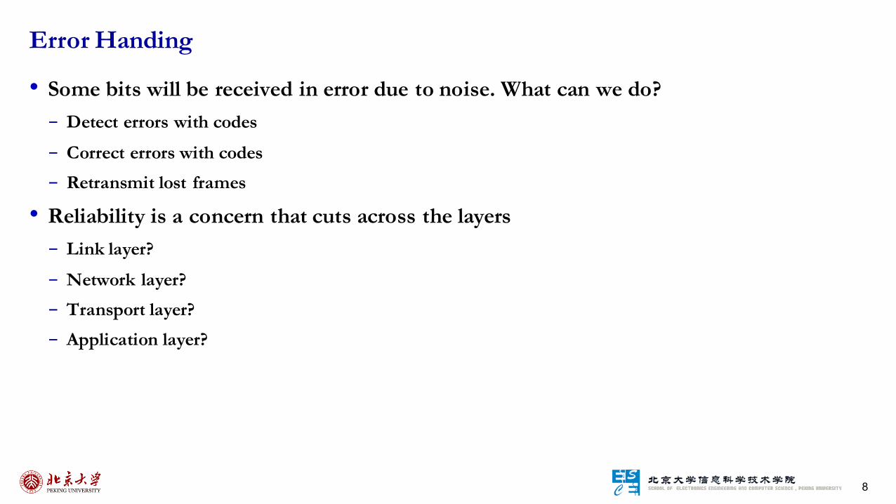
• Some bits will be received in error due to noise. What can we do?- Detect errors with codes
- Correct errors with codes- Retransmit lost frames
• Reliability is a concern that cuts across the layers- Link layer?
- Network layer?- Transport layer?- Application layer?
Error Handing

9
• Problem – Noise may flip received bits
• Approach – Add Redundancy - Error detection codes
§ Add check bits to the message bits to let some errors be detected
- Error correction codes§ Add more check bits to let some errors be
corrected
- Key issue is now to structure the code to detect many errors with few check bits and modest computation
Motivating Example

10
• Codeword consists of D data plus R
check bits
• Sender: - Compute R check bits based on the D data bits;
send the codeword of D+R bits
• Receiver: - Receive D+R bits with unknown errors- Recompute R check bits based on the D data
bits; error if R doesn’t match R’
Using Error Codes
D R=fn(D)
Data bits Check bits
• Intuition for Error Codes- For D data bits, R check bits:
- Randomly chosen codeword is unlikely to
be correct (1/2R); overhead is low
Allcodewords
Correctcodewords

11
• Much early work on codes:- “Error Detecting and Error Correcting Codes”, BSTJ, 1950
• See also:- “You and Your Research”, 1986
• Distance in the context of coding- Distance is the number of bit flips needed to change (D+R)1 to (D+R)2
- Hamming distance of a code§ The minimum distance between any pair of codewords
- Error detection:§ For a code of distance d+1, up to d errors will always be detected
- Error correction:§ For a code of distance 2d+1, up to d errors can always be corrected by mapping to the closest codeword
R.W. Hamming (1915-1998)
Source: IEEE GHN, © 2009 IEEE
12
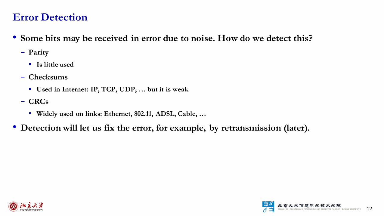
• Some bits may be received in error due to noise. How do we detect this?- Parity
§ Is little used
- Checksums§ Used in Internet: IP, TCP, UDP, … but it is weak
- CRCs§ Widely used on links: Ethernet, 802.11, ADSL, Cable, …
• Detection will let us fix the error, for example, by retransmission (later).
Error Detection

13
• Take D data bits, add 1 check bit that is the sum of the D bits- Sum is modulo 2 or XOR
- Example: 1001100 → 1
• How well does parity work?- What is the distance of the code? 2- How many errors will it detect/correct? 1/0
• What about larger errors?- Odd # of errors
Error Detection – Parity Bit

14
• Idea: sum up data in N-bit words- Widely used in, e.g., TCP/IP/UDP
- Stronger protection than parity• Internet Checksum- Sum is defined in 1s complement arithmetic (must add back carries) – And it’s the negative sum
- Sending1. Arrange data in 16-bit words
2. Put zero in checksum position, add
3. Add any carryover back to get 16 bits
4. Negate (complement) to get sum
- How well does the checksum work?§ What is the distance of the code? 2
§ How many errors will it detect/correct? 1/0
§ What about larger errors? All burst error up to 16
Error Detection – Checksums
1500 bytes 16 bits
- Receiving1. Arrange data in 16-bit words
2. Checksum will be non-zero, add3. Add any carryover back to get 16 bits
4. Negate the result and check it is 0
0001 f203 f4f5 f6f7
+ 220d ------2fffd
fffd + 2 ------
ffff
0000
“The checksum field is the 16 bit one’s complement of the one’s complement sum of all 16 bit words …” – RFC 791
0001 f203 f4f5 f6f7
+(0000)------2ddf0
ddf0 + 2 ------
ddf2
220d

15
• Even stronger protection- Given n data bits, generate k check
bits such that the n+k bits are
evenly divisible by a generator C
• The catch:- It’s based on mathematics of finite
fields, in which “numbers”
represent polynomials
- E.g, 10011010 is x7 + x4 + x3 + x1
• What this means:- We work with binary values and
operate using modulo 2 arithmetic
Error Detection – Cyclic Redundancy Check (CRC)
• Send Procedure:- Extend the n data bits with k zeros
- Divide by the generator value C
- Keep remainder, ignore quotient
- Adjust k check bits by remainder
• Receive Procedure:- Divide and check for zero remainder
• Protection depend on generator- Standard CRC-32 is 10000010 01100000 10001110 110110111
• Properties:- Hamming distance=4, detects up to triple bit errors- Also odd number of errors
- And bursts of up to k bits in error
- Not vulnerable to systematic errors like checksums
Data bits:1101011111Check bits:
C(x)=x4+x1+1C = 10011k = 4

16
• If we had reliable check bits we could use them to narrow down the position of the error- Then correction would be easy
• But error could be in the check bits as well as the data bits!- Data might even be correct
• Intuitions for error correction code- Suppose we construct a code with a Hamming distance of at least 3
§ Need ≥3 bit errors to change one valid codeword into another
§ Single bit errors will be closest to a unique valid codeword
- If we assume errors are only 1 bit, we can correct them by mapping an error to the closest valid codeword§ Works for d errors if HD ≥ 2d + 1
- Visualization of code
Why Error Correction is Hard
A
B
Valid codeword
Error codeword
Single bit error from A
Three bit errors to get to B

17
• Gives a method for constructing a code with a
distance of 3- Uses n = 2k – k – 1, e.g., n=4, k=3- Put check bits in positions p that are powers of 2,
starting with position 1- Check bit in position p is parity of positions with
a p term in their values
• Example: data = 0101, 3 check bits- 7 bit code, check bit positions 1, 2, 4- Check 1 covers positions 1, 3, 5, 7- Check 2 covers positions 2, 3, 6, 7- Check 4 covers positions 4, 5, 6, 7
Hamming Code
Code construction0 1 0 0 1 0 1p1= 0+1+1 = 0, p2= 0+0+1 = 1, p4= 1+0+1 = 0
• To decode:- Recompute check bits
§ With parity sum including the check bit
- Arrange as a binary number
- Value (syndrome) tells error position§ Value of zero means no error
§ Otherwise, flip bit to correct
No Error0 1 0 0 1 0 1p1= 0+0+1+1 = 0 p2= 1+0+0+1 = 0p4= 0+1+0+1 = 0Syndrome = 000, no errorData = 0 1 0 1
Error Correction0 1 0 0 1 1 1p1= 0+0+1+1 = 0p2= 1+0+1+1 = 1,p4= 0+1+1+1 = 1Syndrome = 110, flip position 6Data = 0 1 0 1

18
• Which is better will depend on the pattern of errors. For example:- 1000 bit messages with a bit error rate (BER) of 1 in 10000, i.e., 10% has one error in message
• Which has less overhead?- It still depends! We need to know more about the errors
Detection vs. Correction
Error correction Error detection
Bit errors are random – messages have 0 or maybe 1 error
Need ~10 check bits per messageOverhead: 10
Need ~1 check bits per message plus 1000 bit retransmission 1/10 of the timeOverhead: 1 + 1000*0.1 = 101
Errors come in bursts of 100 –only 1 or 2 messages in 1000 have errors
Need >>100 check bits per messageOverhead: >>100
Need 32? check bits per message plus 1000 bit resend 2/1000 of the time32+1000*0.002 = 34 bits
In general Needed when errors are expected, or when no time for retransmission
More efficient when errors are not expected, and when errors are large when they do occur
19
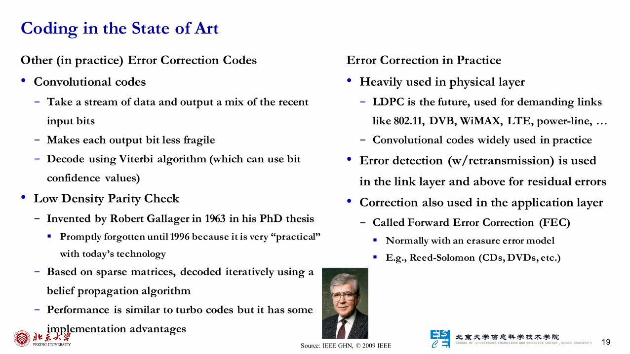
Other (in practice) Error Correction Codes
• Convolutional codes- Take a stream of data and output a mix of the recent
input bits- Makes each output bit less fragile- Decode using Viterbi algorithm (which can use bit
confidence values)
• Low Density Parity Check- Invented by Robert Gallager in 1963 in his PhD thesis
§ Promptly forgotten until 1996 because it is very “practical”
with today’s technology
- Based on sparse matrices, decoded iteratively using a belief propagation algorithm
- Performance is similar to turbo codes but it has some implementation advantages
Coding in the State of Art
Source: IEEE GHN, © 2009 IEEE
Error Correction in Practice
• Heavily used in physical layer- LDPC is the future, used for demanding links
like 802.11, DVB, WiMAX, LTE, power-line, …- Convolutional codes widely used in practice
• Error detection (w/retransmission) is used in the link layer and above for residual errors
• Correction also used in the application layer- Called Forward Error Correction (FEC)
§ Normally with an erasure error model
§ E.g., Reed-Solomon (CDs, DVDs, etc.)

20
• Where in the stack should we place reliability functions?
• Everywhere! It is a key issue- Different layers contribute differently
Context on Reliability
PhysicalLink
NetworkTransportApplication Recover actions
(correctness)
Mask errors(performance optimization)
21
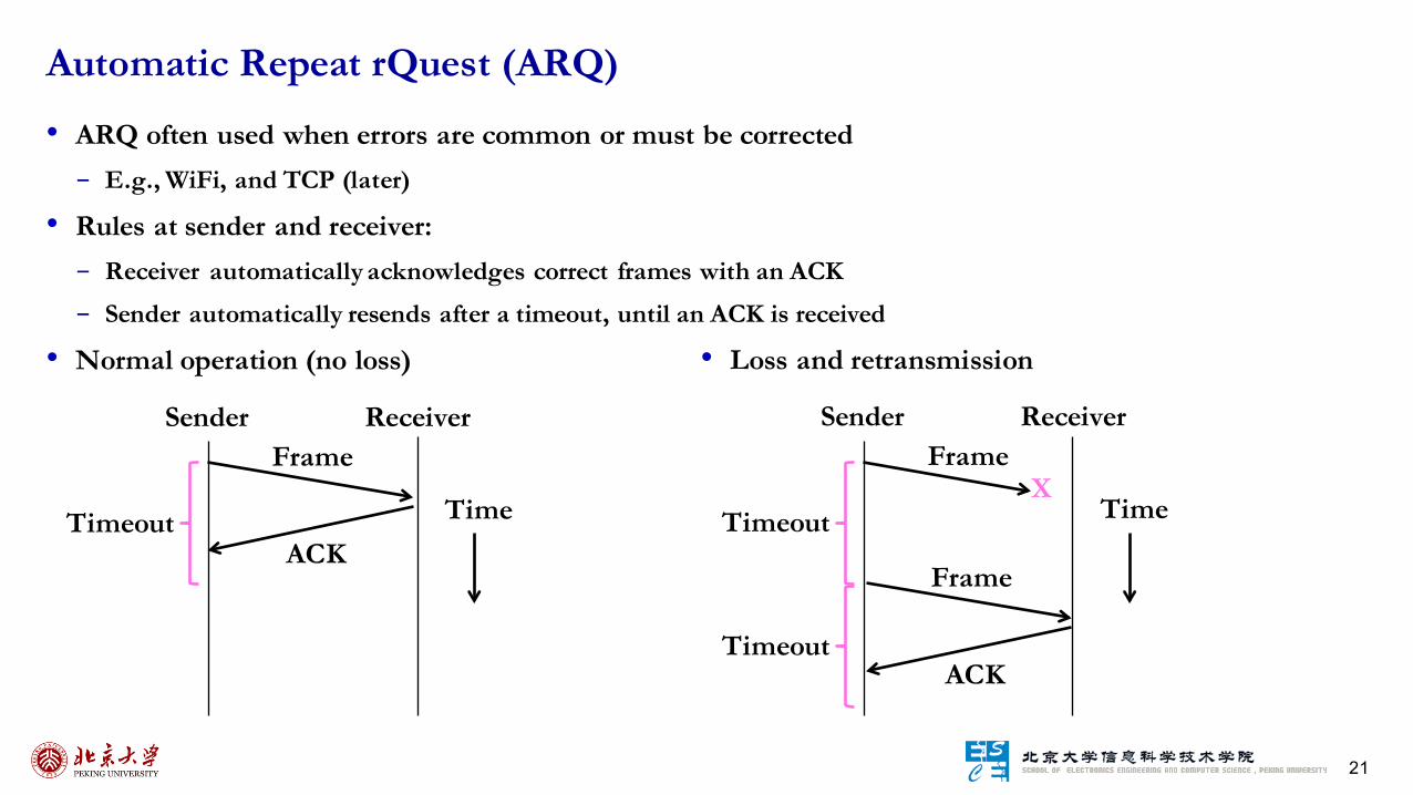
• ARQ often used when errors are common or must be corrected- E.g., WiFi, and TCP (later)
• Rules at sender and receiver:- Receiver automatically acknowledges correct frames with an ACK- Sender automatically resends after a timeout, until an ACK is received
• Normal operation (no loss)
Automatic Repeat rQuest (ARQ)
• Loss and retransmission
Frame
ACKTimeout Time
Sender ReceiverFrame
Timeout Time
Sender Receiver
Frame
ACK
X
Timeout

22
• Two non-trivial issues:- How long to set the timeout? - How to avoid accepting duplicate frames as new frames
• Want performance in the common case and correctness always• Timeout- Timeout should be:
§ Not too big (link goes idle)
§ Not too small (spurious resend)
- Fairly easy on a LAN§ Clear worst case, little variation
- Fairly difficult over the Internet§ Much variation, no obvious bound
§ We’ll revisit this with TCP (later)
So What’s Tricky About ARQ?
• Duplication- What happens if an ACK is lost?
- Or the timeout is early?
Frame
ACK
X
Frame
ACKTimeout
Sender Receiver
New Frame??
Frame
ACK
Frame
ACK
Timeout
Sender Receiver
New Frame??

23
• Frames and ACKs must both carry sequence numbers for correctness
• To distinguish the current frame from the next one, a single bit (two numbers) is
sufficient – called Stop-and-Wait
Sequence Numbers
Frame 0
ACK 0Timeout Time
Sender Receiver
Frame 1
ACK 1
Frame 0
ACK 0
X
Frame 0
ACK 0Timeout
Sender Receiver
It’s a Resend!
Frame 0
ACK 0
Frame 0
ACK 0
Timeout
Sender Receiver
It’s aResend
OK …
In the normal case With ACK Loss With early timeout
24
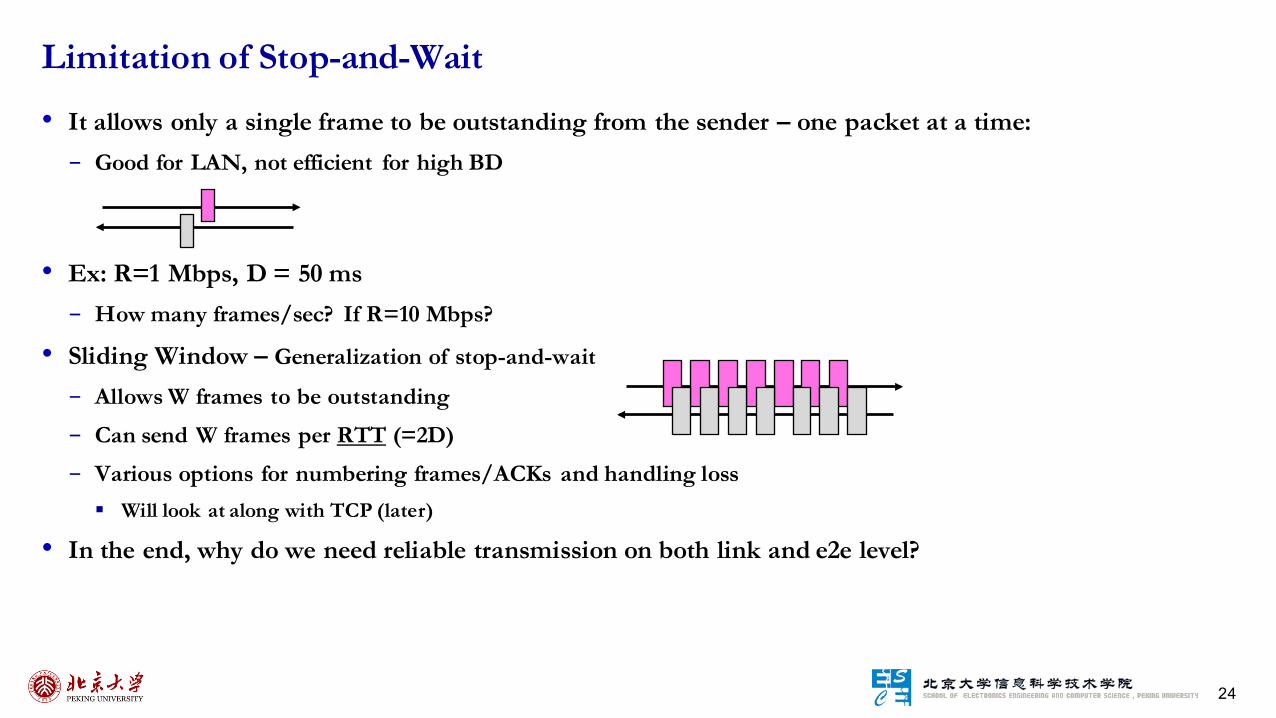
• It allows only a single frame to be outstanding from the sender – one packet at a time:- Good for LAN, not efficient for high BD
• Ex: R=1 Mbps, D = 50 ms- How many frames/sec? If R=10 Mbps?
• Sliding Window – Generalization of stop-and-wait
- Allows W frames to be outstanding- Can send W frames per RTT (=2D)- Various options for numbering frames/ACKs and handling loss
§ Will look at along with TCP (later)
• In the end, why do we need reliable transmission on both link and e2e level?
Limitation of Stop-and-Wait
25
• Framing- Delimiting start/end of frames
• Error Control- Error control and correction, retransmission
• Multiple Access – How to coordinate network access over a broadcast medium? - MAC and CSMA
• (W)LAN- 802.11, modern Ethernet and switching
Topics

26
• Review: TDM and FDM- In TDM a user sends at a high rate a fraction of the time;
in FDM, a user sends at a low rate all the time
- Statically divide a resource§ Suited for continuous traffic, fixed number of users
- Widely used in telecommunications§ TV/radio stations use FDM; Earlier cellular allocates calls us TDM within FDM
• Network traffic is bursty- Load varies greatly over time- Inefficient to always allocate user their ON needs with TDM/FDM
• Multiple access schemes - Multiplex users based on demands – for gains of statistical multiplexing- But communication about channel sharing must use channel itself!
Multiplexing Network Traffic Allows Multiple AccessRate
TimeFDM
TDM
Rate
TimeRate
Time
R
R
Two users, each need R
Rate
Time
R’<2RTogether they need R’ < 2R

27
• Who gets to send a packet next?
• Scheduled multiple access- Explicit coordination ensures that only one node transmits- Looks cleaner, more organized, but …- Coordination introduces overhead – require communication- Not efficient for real traffic – burty and opportunistic
• Assume no-one is in charge- How do nodes share a single link? Who sends when, collision and its detection
• We will look at two kinds of multiple/media/medium access (MAC) protocols- Randomized: nodes randomize their resource access attempts, e.g., (slotted) ALOHA, CSMA/(CD/CA)
§ Good for low load situations
- Contention-free: nodes order their resource access attempts§ Good for high load or guaranteed quality of service situations
Centralized versus Decentralized Multiple Access
Zzzz.Busy! Ho hum

28
• Seminal computer network connecting the Hawaiian islands in the late 1960s- When should nodes send? A new protocol was devised by Norm Abramson …
• Simple idea: - Assume:
§ All frames have the same length and the frame time is T§ Node just sends when it has traffic. § Population of stations attempt to transmit within period T follows Poisson distribution§ G be the average # of stations that begin transmission within period T§ If there was a collision (no ACK received) then wait a random time and resend
- Probability that exactly 𝒙 stations begin transmission during T: 𝑷 𝑿 = 𝒙 = 𝑮𝒙𝒆'𝑮
𝒙!
- P(success) = P(exactly 1 node tx in [t0, t0+T]) P(no nodes tx in [t0-T,t0]) = 𝑮𝒆)𝑮𝒆)𝑮
• Simple, decentralized protocol that works well under low load!- Not efficient under high load – analysis shows at most 18% efficiency
• Slotted ALOHA: divides time into slots and efficiency goes up to 36%- Transmission can only start at the beginning of each slot of period T
ALOHA Network and ALOHA Protocol

29
• ALOHA inspired Bob Metcalfe to invent Ethernet
for LANs in 1973- Nodes share 10 Mbps coaxial cable- Hugely popular in 1980s, 1990s
Classic Ethernet
:©2009IEEE

30
• Improve ALOHA by carrier sensing: make sure the channel is idle before we send- If channel sensed idle: transmit entire frame
- If channel sensed busy, defer transmission- Can do easily with wires, not wireless
• Collision can still occur- Still possible to listen and hear nothing when another node is sending because of delay
- Entire packet transmission time wasted§ Distance and propagation delay play role in determining collision probability
• CSMA is a good defense against collisions only when BD is small, i.e., << packet
Carrier Sense Multiple Access (CSMA)
X

31
• Collisions are detected by listening on the medium and comparing the
received and transmitted signals- Only one transmitter can transmit at a time
• Can reduce the cost of collisions by detecting them and aborting by
sending jam signal the rest of the frame time- Want everyone who collides to know that it happened ASAP!- If the frame is too short, sender may realize collision happens too late!- Time window in which a node may hear of a collision is 2D seconds
§ D: propagation delay
• Impose a minimum frame size that lasts for 2D seconds- So transmission can’t finish before collision
§ The first bit in another transmission arrives
- Ethernet minimum frame is 64 bytes
• How do we avoid that two nodes retransmit at the same time collision?
CSMA/CD (with Collision Detection)
X X X X X X X XJam! Jam!
X
X
Spatial layout of nodes

32
Procedure
• NIC receives datagram from network layer, creates frame- If NIC senses channel idle, starts frame transmission. - Else if NIC senses channel busy, waits until channel idle, then
transmits.
• If NIC transmits entire frame without detecting another transmission, NIC is done with frame!
• If NIC detects another transmission while transmitting,
aborts and sends jam signal• After aborting, NIC enters BEB: - After mth collision, NIC chooses K at random from {0,1,2, …,
2m-1}. NIC waits K x 512 bit times, returns to Step 2§ After ten or more collision, choose K from {0,1,2,3,4, …, 1023}
- Longer backoff interval with more collisions
Binary Exponential Backoff (BEB)
Packet?
Sense Carrier
Discard Packet
Send Detect Collision
Jam channel b=CalcBackoff();
wait(b);attempts++;
No
Yes
attempts < 16
attempts == 16
• Exponentially increasing random delay- Infer # of senders from # of collisions- More senders → increase wait time
• BEB doubles interval for each successive collision- Quickly gets large enough to work
- Very efficient in practice

33
• What should a node do if the line is busy?
• Idea: wait until it is done, and send • Problem is that multiple waiting nodes will queue up then collide- More load, more of a problem
• Intuition for a better solution- If there are N queued senders, we want each to send next with
probability 1/N, but what’s N?
• p-persistent scheme- Transmit with probability p once the channel goes idle
- Delay the transmission by tprop with 1-p
• Non-persistent scheme- Reschedule transmission for a later time based on a delay distribution- Sense the channel at that time, and repeat
CSMA “Persistence” – scalability issue
What now?
Now! Now!Uh oh
Send p=½WhewSend p=½

34
• Classic Ethernet, or IEEE 802.3 - Most popular LAN of the 1980s, 1990s
§ 10 Mbps over shared coaxial cable, with baseband signals
§ Multiple access with “1-persistent CSMA/CD with BEB”
• Frame Format- Has addresses to identify the sender and receiver
- CRC-32 for error detection; no ACKs or retransmission
- Start of frame identified with physical layer preamble
Ethernet, or IEEE 802.3
• Modern Ethernet- Use point-to-point “links” with switches
§ Store-and-forward, not multiple access, but still called
Ethernet
§ Very common in wired networks, at multiple layers
Switch
Twisted pairSwitch ports
Packet from Network layer (IP)

35
• Nodes A and C are hidden terminals when sending to B- Can’t hear each other (to coordinate) yet collide at B- We want to avoid the inefficiency of collisions
• Nodes B and C are exposed terminals when sending to A and D- Can hear each other yet don’t collide at receivers A and D- We want to send concurrently to increase performance
• Node C will almost always “win” if there is a collision at receiver D- This “capture effect” can lead to extreme unfairness and even starvation- Power control is the solution, but very difficult to manage in a
non-provisioned environment
• Collision detection is not practical in radio environment- While transmitting, a station cannot distinguish incoming weak signals from noise – its own signal is too strong- Transmitter cannot detect competing transmitters
Wireless Complications – Different Coverage Areas

36
• MACA uses a short handshake instead of CSMA (Karn, 1990)- 802.11 uses a refinement of MACA
• Protocol rules:1. A sender node transmits a RTS (Request-To-Send, with frame length)2. The receiver replies with a CTS (Clear-To-Send, with frame length)3. Sender transmits the frame while nodes hearing the CTS stay silent
§ Collisions on the RTS/CTS are still possible, but less likely
• A → B with hidden terminal C- A sends RTS, to B
- B sends CTS, to A, and C too
Possible Solution: Multiple Access Collision Avoidance (MACA)
DCBARTS
DCBARTS
CTSCTS
Alert!
• B → A, C→ D as exposed terminals- A and D send CTS to B and C
- A and D send CTS to B and C
DCBARTSRTS
DCBARTSRTS
CTSCTS
All OKAll OK

37
• CSMA is good under low load:- Grants immediate access
- Little overhead (collisions)
• But not so good under high load:- High overhead (expect collisions)- Access time varies (lucky/unlucky)
• We want to do better under load!
Issues with Random Multiple Access

38
• Define an order in which nodes get a chance to send- Or pass, if no traffic at present
• Arrange nodes in a ring; token rotates “permission to send” to each node in turn• Advantage - Fixed overhead with no collisions
§ More efficient under load
- Regular chance to send with no unlucky nodes- Predictable service, easily extended to guaranteed quality of service
• Disadvantage- More things that can go wrong than random access protocols!
§ E.g., what if the token is lost?
- Higher overhead at low load- Latency
Turn-Taking Multiple Access Protocols – Token Ring as an Example
Node
Direction oftransmission
Token

39
• Framing- Delimiting start/end of frames
• Error Control- Error control and correction, retransmission
• Multiple Access- MAC and CSMA
• (W)LAN – How does your packet go into the network?- 802.11, modern Ethernet and switching
Topics

40
• Throughput- MAC protocol should maximize capacity of
the wireless medium
• Number of nodes- Hundred of nodes
• Connection to backbone LAN- Accommodation for mobile users and ad
hoc wireless networks
• Service area- Coverage area has a diameter of 100 – 300 m
• Battery power consumption- Sleep mode is a critical design
WLAN Design Space and Requirements
• Transmission robustness and security- Vulnerable to interference and network
eavesdropping
• Collocated network operation- Interference of coexisted wireless networks
• License-free operation- No need to secure a license for the frequency band
• Handoff/roaming- Layer 2 client mobility
• Dynamic configuration- Automated addition, deletion and relocation of end
systems without disruption to other users
41
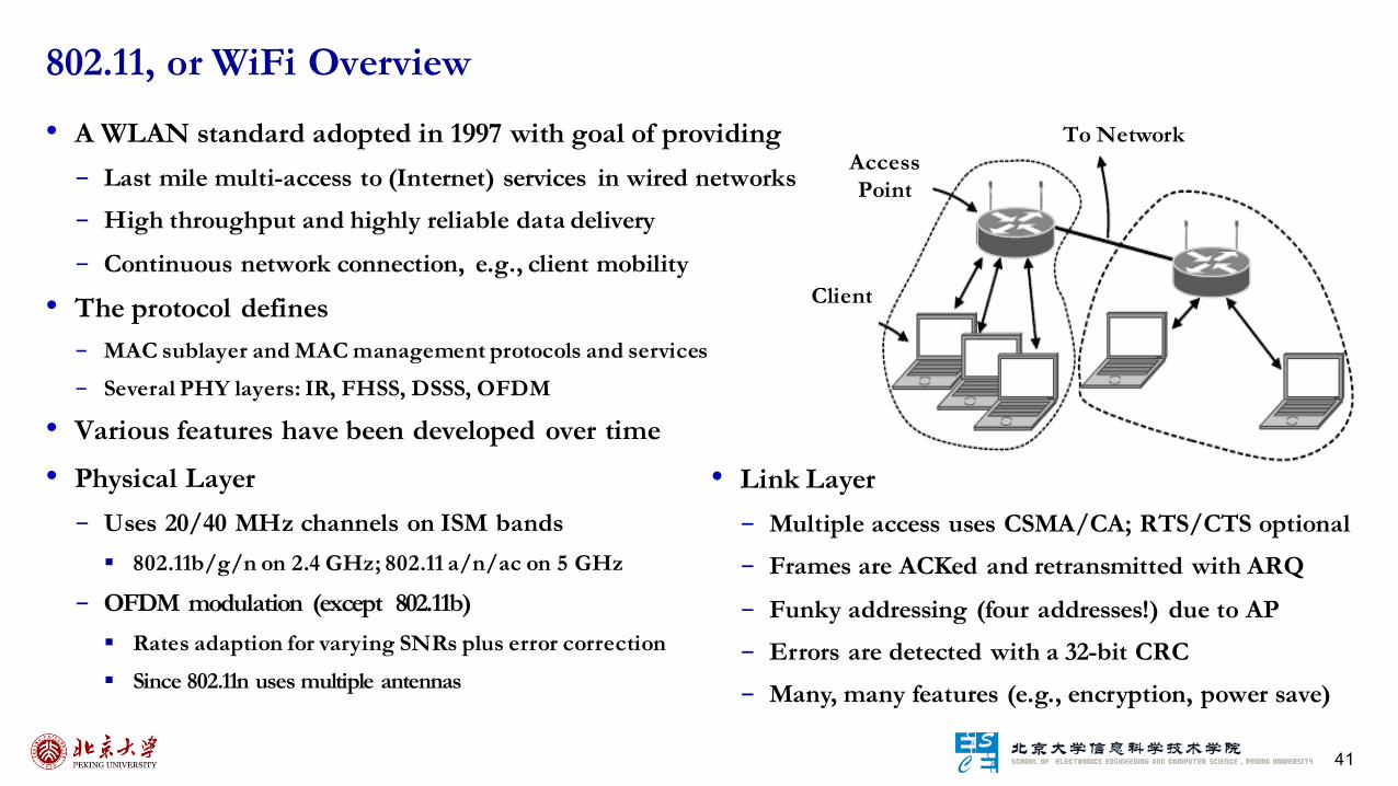
• A WLAN standard adopted in 1997 with goal of providing- Last mile multi-access to (Internet) services in wired networks- High throughput and highly reliable data delivery
- Continuous network connection, e.g., client mobility
• The protocol defines- MAC sublayer and MAC management protocols and services
- Several PHY layers: IR, FHSS, DSSS, OFDM
• Various features have been developed over time
• Physical Layer- Uses 20/40 MHz channels on ISM bands
§ 802.11b/g/n on 2.4 GHz; 802.11 a/n/ac on 5 GHz
- OFDM modulation (except 802.11b)§ Rates adaption for varying SNRs plus error correction
§ Since 802.11n uses multiple antennas
802.11, or WiFi Overview
AccessPoint
Client
To Network
• Link Layer- Multiple access uses CSMA/CA; RTS/CTS optional - Frames are ACKed and retransmitted with ARQ
- Funky addressing (four addresses!) due to AP- Errors are detected with a 32-bit CRC- Many, many features (e.g., encryption, power save)

42
• IEEE 802.11 is a standard
• Wi-Fi = “Wireless Fidelity” is a trademark
• Fidelity = Compatibility between wireless equipment from different manufactures
• Wi-Fi Alliance is a non-profit organization that does the compatibility testing- WiFi.org
• 802.11 has many options and it is possible for two equipment based on 802.11 to be
incompatible.
• All equipment with “Wi-Fi” logo have selected options such that they will
interoperate.
Wi-Fi vs. IEEE 802.11?
43
• Infrastructure mode: stations communicate with one or more access points which are
connected to the wired infrastructure, with two modes of operation:- Distributed Control Functions – DCF
§ What is deployed in practice
- Point Control Functions – PCF§ PCF is rarely used – inefficient, not discussed in this course
• Alternative is “ad hoc” mode: multi-hop, assumes no infrastructure- Rarely used, e.g. military- Hot research topic!
§ Sensor, Vehicular, Drone, Millimeterwave
Infrastructure and Ad Hoc Mode

44
802.11 Architecture
Infrastructure Network
• Station (STA)- Terminal with access mechanisms to the wireless medium and radio contact to the access point
• Access Point (AP)- Station integrated into the wireless LAN and the distribution system
• Basic Service Set (BSS)- Set of stations associated with one AP that provides access to wired infrastructure
• Extended Service Set (ESS)- A set of infrastructure BSSs that work together – aggregation of APs from BSSs
• Distribution System (DS)- Interconnection network to form one logical network (ESS) based on BSSs
• Portal- Bridge to other (wired) networks
• Independent BSS (IBSS)- Set of computers in ad-hoc mode
STASTA
STASTAIBSS IBSSAd Hoc Network
Distribution System
Portal
802.x LAN
AccessPoint
802.11 LAN
BSS2
802.11 LAN
BSS1AccessPoint
STA1
STA2STA3
ESS

45
• Carrier Sense Multiple Access (with Collision Avoidance)- Frame is transmitted only when medium is sensed idle for
now and after an Distributed Coordination Function
interframe space (DIFS)- The the channel is sensed busy, the station defers
transmission until the current transmission is over§ Busy time can be sensed by physical/virtual carrier sensing
- Once current transmission is over, the station delays another DIFS, sends the frame if the channel is idle not only for now but also after a random backoff (contention window). § The backoff timer is halted if the medium becomes busy and
resume once it becomes idle
§ If the frame is sent and an ACK is not received after a SIFS, then
retransmit after the random backoff procedure
- RTS/CTS can be turned off to reduce overhead
802.11 MAC Overview
NAV

46
Physical Carrier Sense
• Clear Channel Assessment (CCA): listens the received energy on the radio interface
• Carrier Sense: the ability of the receiver to detect (and decode) an incoming WiFi signal preamble- “BUSY” will be held for the length of the received frame as
indicated in the frame’s PLCP Length field (in us for full frame MPDU payload)
- Indicates the medium is busy for the current frame
• Energy Detection: the ability of the receiver to detect the non-WiFi energy level present on the current channel - Based on noise floor, ambient energy, interference sources
and unidentifiable/corrupted WiFi transmissions
- Sample rate and sensitivity level needs to be engineered
802.11 Carrier Sense Fundamentals
Virtual Carrier Sense
• Network Allocation Vector (NAV)- Every frame has a “Duration ID” which
indicates how long the medium will be busy.§ RTS has duration of RTS + SIF + CTS + SIF +
Data + SIF + ACK
§ CTS has duration of CTS + SIF + Frame + SIF
+ ACK
§ Data has duration of Data + SIF + ACK
§ ACK has a duration of ACK
- All stations keep a “NAV” timer in which they record the duration of the each frame they hear.
- Stations do not need to sense the channel for idle status until NAV becomes zero.

47
Use of RTS/CTS

48
• Time critical services use Point Coordination Function• The point coordinator allows only one station to access
• Coordinator sends a beacon frame to all stations. Then uses a polling frame to allow a
particular station to have contention-free access• Contention Free Period varies with the load.
Time Critical Services
49
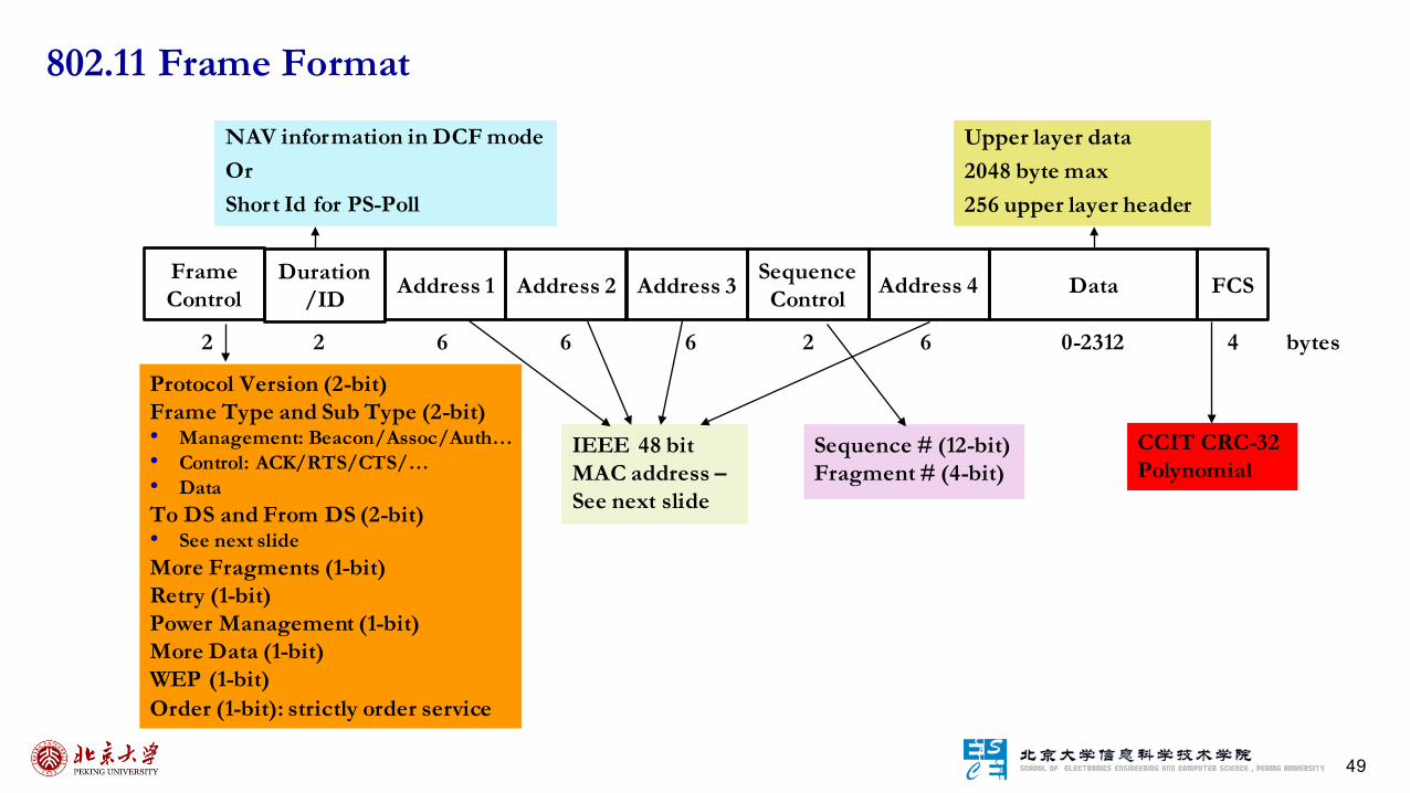
802.11 Frame Format
Protocol Version (2-bit)Frame Type and Sub Type (2-bit)• Management: Beacon/Assoc/Auth…• Control: ACK/RTS/CTS/…• DataTo DS and From DS (2-bit)• See next slideMore Fragments (1-bit)Retry (1-bit)Power Management (1-bit)More Data (1-bit)WEP (1-bit)Order (1-bit): strictly order service
2 2 6 6 6 2 6 0-2312 4 bytes
NAV information in DCF modeOrShort Id for PS-Poll
IEEE 48 bit MAC address –See next slide
Sequence # (12-bit)Fragment # (4-bit)
CCIT CRC-32 Polynomial
Upper layer data2048 byte max256 upper layer header
FrameControl
Duration/ID Address 1 FCSDataAddress 2 Address 3 Sequence
Control Address 4

50
802.11 Frame Address Fields
To DS From DS Message Address 1 Address 2 Address 3 Address 4
0 0 station-to-station frames in an IBSS; all mgmt/control frames DA SA BSSID --
0 1 From AP to station DA BSSID SA --
1 0 From station to AP BSS ID SA -- DA
1 1 From one AP to another in same DS RAP TAP SA DA
Ad hoc
from AP
to AP
in DS
Physical Receiver
Physical Transmitter
Logical Transmitter
Logical Receiver
RA: Receiver Address
TA: Transmitter Address
DA: Destination Address
SA: Source Address
BSSID: MAC address of AP in an infrastructure BSS

51
• All modern WiFi standards allow for multiple bit rates- 802.11b has 4 rates, more recent standards have 10s- Allows for adaptation to channel conditions
- Specific rates dependent on the version and vendor- Packets have multi-rate format
§ Different parts of the packet are sent at different rates
• Algorithm for selecting the rate is not defined by the standard – left to vendors
• Many factors influence packet delivery:- Fast and slow fading: nature depends strongly on the environment- Interference versus WiFi contention: response to collisions is different- Random packet losses: can confuse “smart” algorithms- Hidden terminals: decreasing the rate increases the chance of collisions
• Transmit rate adaptation: how does the sender pick?
Multi-bit Rate
52
• Goal: pick rate that provides best throughput
• “Trial and Error”: senders use past packet success or failures to adjust transmit rate- Sequence of x successes: increase rate- Sequence of y failures: reduce rate- Hard to get x and y right- Random losses can confuse the algorithm- Many variants – RRAA
• Signal strength: stations use channel state information to pick transmit rate- Use path loss information to calculate “best” rate- Assumes a relationship between PDR and SNR
§ Need to recover if this fails, e.g., hidden terminals
- Tends to be a bit harder to manage – Charm
High Level Designs of Rate Adaptation

53
• Association management
• Handoff/Roam
• Security: authentication and privacy
• Power management
• QoS
802.11 Management and Control Services

54
• Service Set Identifier (SSID) – identifier for a WLAN- Human readable. E.g., “Wifeless EECS”, “Password is not 123456”- Mechanism used to segment wireless networks
§ Effectively the name of the wireless network – a set of multiple interconnected wireless BSSs that share the same SSID
§ Multiple independent wireless networks can coexist in the same location – Extended Service Set (ESS)
- Each AP is programmed with a SSID that corresponds to its network
- Client computer presents correct SSID to access AP- Security Compromises
§ AP can be configured to “broadcast” its SSID
§ Broadcasting can be disabled to improve security
§ SSID may be shared among users of the wireless segment
• Basic Service Set Identifier (BSSID)- The MAC address of the AP- A subset of SSID
WLAN Identification
Distribution System
Portal
802.x LAN
AccessPoint
802.11 LAN
BSS2
802.11 LAN
BSS1AccessPoint
STA1
STA2STA3
ESS

55
• Stations must associate with an AP before they can use the wireless network- AP must know about them so it can forward packets- Often also must authenticate
• Association is initiated by the wireless host – involves multiple steps:- Scanning: finding out what access points are available
§ Active/Passive scanning
- Selection: deciding what AP (or ESS) to use- Authentication: needed to gain access to secure APs – many options possible- Association: protocol to “sign up” with AP – involves exchange of parameters
• Disassociation: station or AP can terminate association- Client send disassociation request or timeout
• Remember: this is layer 2 connectivity- Don’t guarantee a higher layer connectivity, e.g., Internet access
Association Management Overview

56
• Stations can detect AP based by scanning- Passive Scanning: station simply listens for
Beacon and gets info of the BSS§ Beacons are sent roughly 10 times per second
§ Power is saved
- Active Scanning: station transmits Probe
Request; elicits Probe Response from AP§ Saves time + is more thorough
§ Wait for 10-20 msec for response
- Scanning all available channels can become very time consuming!§ Especially with passive scanning
§ Cannot transmit and receive frames during
most of that time – not a big problem during
initial association
Association Management: Scan, Select and Join
• Selecting a BSS or ESS typically must involve the user- What networks do you trust? Are you willing to pay?- Can be done automatically based on stated user
preferences
• The wireless host selects the AP it will use in an ESS
based on vendor-specific algorithm- Uses the information from the scan- Typically simply joins the AP with the strongest signal
• Associating with an AP- Synchronization in Timestamp Field and frequency- Adopt PHY parameters
- Other parameters: BSSID, WEP, Beacon Period, etc.
57
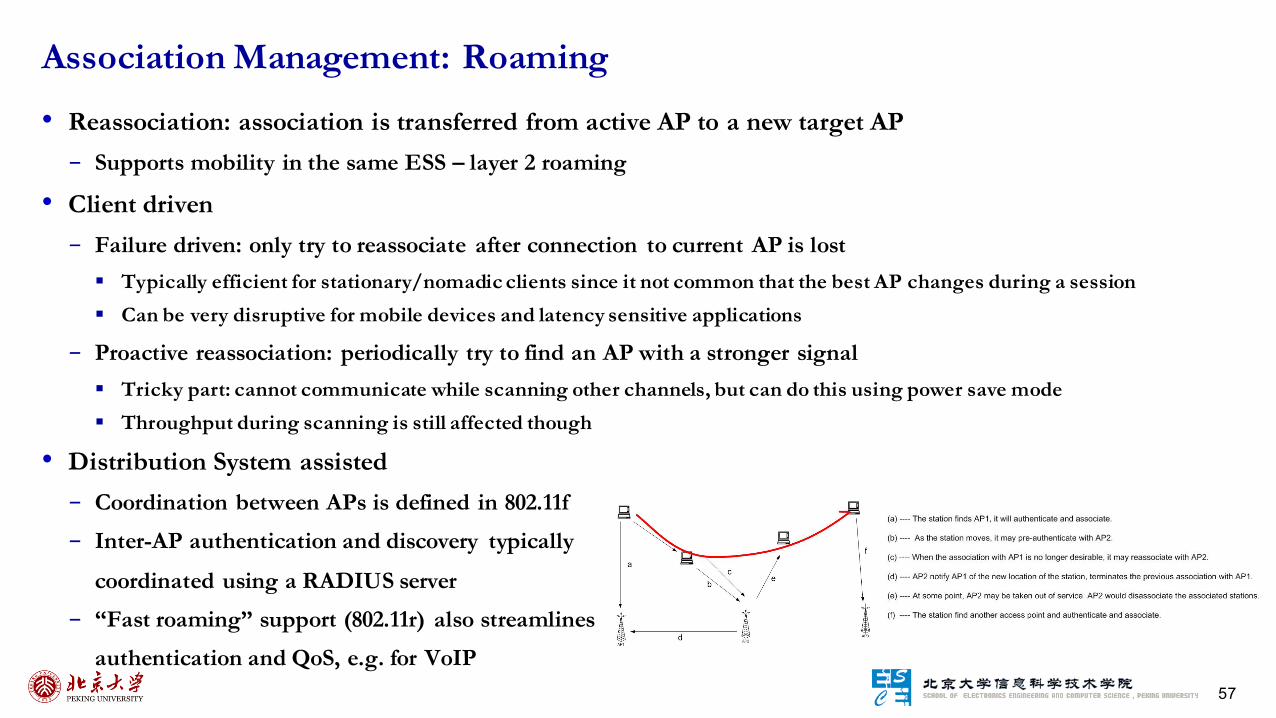
• Reassociation: association is transferred from active AP to a new target AP- Supports mobility in the same ESS – layer 2 roaming
• Client driven- Failure driven: only try to reassociate after connection to current AP is lost
§ Typically efficient for stationary/nomadic clients since it not common that the best AP changes during a session§ Can be very disruptive for mobile devices and latency sensitive applications
- Proactive reassociation: periodically try to find an AP with a stronger signal§ Tricky part: cannot communicate while scanning other channels, but can do this using power save mode § Throughput during scanning is still affected though
Association Management: Roaming
• Distribution System assisted- Coordination between APs is defined in 802.11f- Inter-AP authentication and discovery typically
coordinated using a RADIUS server- “Fast roaming” support (802.11r) also streamlines
authentication and QoS, e.g. for VoIP

58
802.1x and EAP Protocol Execution
WPA/WEP encryption key
Access toDHCP server

59
• Requirements- Authentication: only allow authorized stations to associate with and use the AP- Confidentiality: hide the contents of traffic from unauthorized parties
- Integrity: make sure traffic contents is not modified while in transit
WLAN Security Discussion
• Examples- Insertion attacks: unauthorized Clients or AP
§ Client: reuse MAC or IP address – free service on
“secured” APs
§ AP: impersonate an AP, e.g., use well known name
- Interception and unauthorized monitoring§ Packet Analysis by “sniffing” – listening to all traffic
- Brute Force Attacks Against AP Passwords§ Dictionary Attacks Against SSID
- Encryption Attacks§ Exploit known weaknesses of WEP
- Misconfigurations, e.g., use default password
- Jamming – denial of service§ Cordless phones, baby monitors, leaky microwave oven, etc.

60
• Use WPA2- Widely supported today- If not available, use WEP or WPA
§ Better than no security plus some possible legal benefits
• Change the default configuration of your AP:- Change default passwords on APs- Don’t name your AP by brand name- Don’t name your AP by model #- Change default SSID
• Use MAC filtering if available• Use a VPN or application layer encryption- Must assume that wireless segment is untrusted
- Provides end-to-end encryption – is what you want!
Best Practices for WiFi Security

61
• Goal: to enhance battery life of the (mobile) stations
• Observation: idle receive state dominates LAN adapter power consumption over time• Simple idea: Allow idle stations to power off their NIC (go into sleep mode) while still maintaining an
active session- AP keeps track of stations in Power Savings mode and buffers their packets
§ Traffic Indication Map (TIM) is included in beacons to inform which power-save stations have packets waiting at the AP
- Power Saving stations wake up periodically and listen for beacons§ If they have data waiting, they can send a PS-Poll to request that the AP sends their packets
• Timing Synchronization Function (TSF) assures AP and stations are synchronized- Synchronizes clocks of the nodes in the BSS via beacon frames- On a commercial level, industry vendors assume the synchronization to be within 25 microseconds
• Broadcast/multicast frames are also buffered at AP- Sent after beacons that includes Delivery Traffic Indication Map (DTIM)- AP controls DTIM interval
Power Management
62
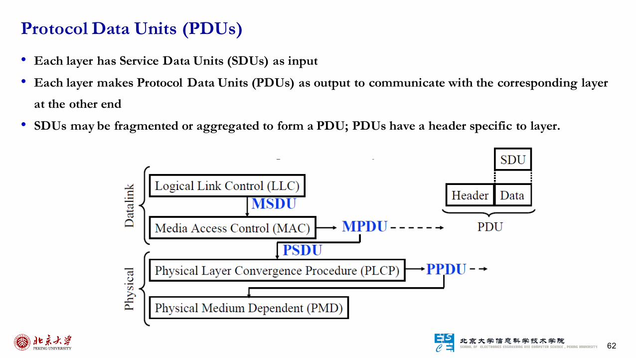
• Each layer has Service Data Units (SDUs) as input
• Each layer makes Protocol Data Units (PDUs) as output to communicate with the corresponding layer at the other end
• SDUs may be fragmented or aggregated to form a PDU; PDUs have a header specific to layer.
Protocol Data Units (PDUs)

63
• 802.11a – 1999: PHY Standard: 8 channels: OFDM, up to 54 Mbps in the 5 GHz band
• 802.11b – 1999: PHY Standard: 3 channels: DSSS, up to 11 Mbps in the 2.4 GHz band. • 802.11g – 2003: PHY Standard: 3 channels: OFDM and PBCC, extend 802.11b to 20+ Mbps
• 802.11n – 2009: PHY/MAC Standard: MIMO, Enhancements for higher throughput (+100 Mbps) • 802.11ac – 2013: PHY/MAC Standard: Enhancements to support 0.5-1 Gbps in < 5 GHz band• 802.11ad – 2012: PHY/MAC Standard: Enhancements to support 1+ Gbps in < 60 GHz band
• Others: - 802.11c: Bridge operation at 802.11 MAC layer- 802.11d: MAC Standard: support for multiple regulatory domains (countries)- 802.11e: MAC Standard : QoS and security support: supported by many vendors- 802.11f: Inter-Access Point Protocol: deployed- 802.11h: MAC Standard: spectrum managed 802.11a (TPC, DFS): standard- 802.11i: MAC Standard: Enhance security and authentication mechanisms
Several Primary 802.11 Amendments

64
802.11 PHY Layer Standards


![An Active-Passive Measurement Study of TCP Performance ...soar.group/pubs/HSRNet.MobiCom19.pdfas LTE-railway (LTE-R) [8], a new standard being discussed for the next-generation private](https://img.pdfslide.net/doc/110x75/5f07f0507e708231d41f841c/an-active-passive-measurement-study-of-tcp-performance-soargrouppubs-as-lte-railway.jpg)