Embed Size (px)
Citation preview

05-212r0 SAS-2 System design considerations 1
05-212r0 SAS-2 System design considerations
Compiled by Barry Olawskyand Rob Elliott, HP
(Namafjall mud pits Iceland 2003)

05-212r0 SAS-2 System design considerations 2
SAS storage system product sectors• Internal storage (e.g.,
ProLiant servers) typically include a backplane and cable− Increasing use of board-to-
board connectors is expected
• External storage (e.g. MSA) designs include several printed circuit boards with SAS traversing multiple board-to-board connectors
• Various external cable lengths for SAS attached designs
HP MSA family
HP Proliant DL360
05-212r0 SAS-2 System design considerations 3
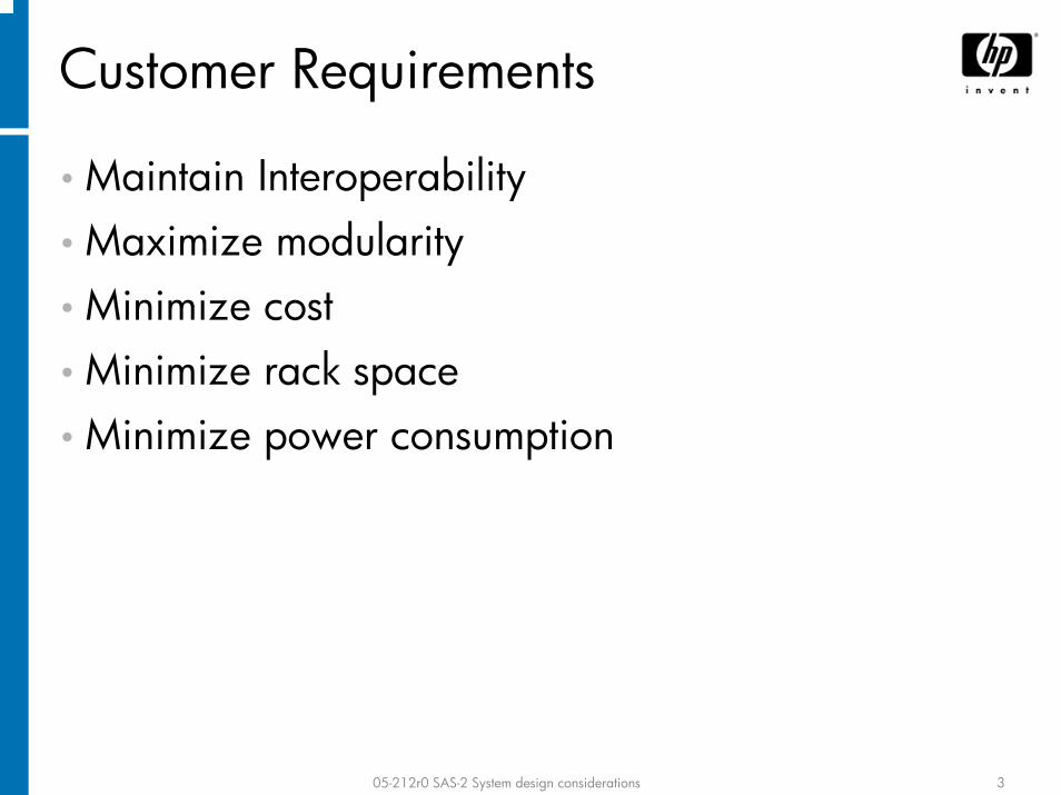
Customer Requirements
• Maintain Interoperability• Maximize modularity• Minimize cost• Minimize rack space• Minimize power consumption

05-212r0 SAS-2 System design considerations 4
Interoperability
• SAS-2 devices must interoperate with SAS 1.5/3 Gbps devices− SAS-1.1 HBAs/drives/expanders must work with SAS-2
HBAs/drives/expanders at 1.5 Gbps/3 Gbps
• Mixed needs regarding 6 Gbps over existing cables/connectors/backplanes:
• Mini SAS 4i (SFF-8087) and Mini 4x (SFF-8088) cables must work• SAS 4i (SFF-8484) cables must work• SAS 4x (SFF-8470) cables – stretch goal
• SAS-2 must fully support SATA drives− 1.5 Gbps, 3 Gbps, and 6 Gbps− Must support off-the-shelf drives using Gen 1i/Gen 2i (400 mV)
signal levels; cannot assume Gen 1x/Gen 2x capability− Work with SATA IO to ensure interoperability with 6 Gbps

05-212r0 SAS-2 System design considerations 5
Modularity• Designs are including more connector interfaces− Placed based on appropriate functional boundaries− Interconnect budget must include more connectors

05-212r0 SAS-2 System design considerations 6
Cost• Don’t require expanders/port selectors just to
redrive signals if the ASICs could have driven stronger signals and received weaker signals
• External cable costs make Ethernet/iSCSI attractive

05-212r0 SAS-2 System design considerations 7
Space• Interconnect solutions need to be small−Mini SAS connectors helpful−Some application for an 8-wide connector to replace two
4-wide connectors− Prefer to increase data rate rather than increase
connector/cable width
HP BP30p and BP10e server blades

05-212r0 SAS-2 System design considerations 8
Power consumption• Turn off unused phys−Dual-port disk drive in a
server never uses the second port
−May not use all phys in high port-count expanders in all designs
• Consider SATA-style interface power management−Compared to power savings
from stopping drives from spinning, savings are trivial
−But, every Watt adds up
05-212r0 SAS-2 System design considerations 9
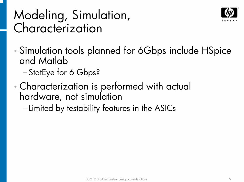
Modeling, Simulation, Characterization
• Simulation tools planned for 6Gbps include HSpice and Matlab−StatEye for 6 Gbps?
• Characterization is performed with actual hardware, not simulation− Limited by testability features in the ASICs

05-212r0 SAS-2 System design considerations 10
System Audit• Ensures integrity of design• Time-domain testing with TDR of PCB traces,
connector footprints, and connector interfaces• Amplitude and jitter measurements for transmitter
and receiver• Vector Network Analyzer (VNA) and TDR used for
cables− Full VNA measurements could be used on backplanes in
the future (SDD21 now)

05-212r0 SAS-2 System design considerations 11
Receiver Visibility
• Particularly if advanced receive equalization is used…• Provide eye visibility inside receiver (after equalizers)
− EDN magazine The Perfect Probe by Howard Johnson 10/14/2004 • http://www.sigcon.com/Pubs/edn/ThePerfectProbe.htm
− On-chip digital sampling scope− Comparator with adjustable reference level and clock phase
• Hold one steady and walk the other while receiving data− Output the results (effectively a bitmask of an eye diagram) in-band
(e.g. log page) and/or out-of-band (e.g. JTAG)
• Include an output pin in the ASIC that toggles when a bit error is detected
• Need better access to phy error registers− Particularly via out-of-band interface if the SAS link has problems
• Need more phy error registers

05-212r0 SAS-2 System design considerations 12
Phy Controls• More transmitter configuration settings
− 8-16 choices ideal− Amplitude – e.g. 200 mV to 1600 mV in 200 mV increments
• Midrange settings allow zeroing in on one setting that works in many different interconnects
• Tuning expanders/HBAs to meet the tight SATA receive window is difficult• Low levels help test the other device’s receiver without requiring a lossy
interconnect− Precompensation – e.g. 0% to 56% cutback in 8% increments− Slew rates
• More receiver configuration settings− Equalizer boost amplitude(s)− Rx Loss thresholds – e.g. 50-250 mV in 50 mV increments
• Standard mechanisms to change settings− Some vendors use vendor-specific mode pages, others vendor-specific
commands, others special firmware loads• Very difficult to manage and use effectively• Should be one mechanism supported by all devices• Develop standard lab tools to support this mechanism
− Sideband mechanism desired (JTAG, I2C, serial port) to change while running real IO traffic in the real system

05-212r0 SAS-2 System design considerations 13
Phy Test Patterns• BIST interface
− Availability of BIST enables improved system characterization and reduced error rates
− Commonality would greatly improve proficiency and reduce test setup time while increasing test coverage
− Start test patterns without software involvement• Don’t want to wait for OS driver/firmware to be debugged when an
ASIC arrives• Don’t want to wait for an HBA that works to start testing a drive• Out-of-band debug interfaces: serial port (UART), JTAG, I2C, USB, …• Is JTAG a common denominator for all vendors?
• Common test pattern sets (more than just CJPAT) will provide a far more effective characterization− PRBS-7, CJTPAT, D10.2, K28.5, ALIGN(0), ALIGN(1), user-defined
20-bit pattern− When testing an interconnect, patterns worse than real patterns (e.g.
PRBS-7) are helpful− Prefer to use real phys rather than test equipment – real edge rates,
real loading, real crosstalk, etc.

05-212r0 SAS-2 System design considerations 14
Phy Margin Testing
• Two techniques have proven useful to test a receiver− Reduce transmitter amplitude (minimal jitter)− Induce jitter via over- and under-precompensation in the
transmitter−Other suggestions?
• Testing should be done in real systems− Test while running full I/O on the rest of the ASIC
• e.g. other SAS phys, PCI-X/PCI-E phys, memory busses, etc. are fully operational
− Test under worst-case conditions (power, temperature)− Test with worst-case silicon

05-212r0 SAS-2 System design considerations 15
• SAS-1.1 requires a BER of 10-12
− Probability of less than 1 error in every 1012 bits in each TxRx connection− TxRx connection covers just one direction
Bit Error Ratio (BER) meaning
1.5 Gbps 3 Gbps 6 Gbps11.1 min 5.55 min 2.77 min
1.5 Gbps 3 Gbps 6 Gbps5.55 min 2.77 min 1.38 min
1.5 Gbps 3 Gbps 6 Gbps8.33 sec 4.16 sec 2.07 sec
• If each direction has independent probabilities of error P(A) and P(B)− P(A or B or both) = P(A) + P(B) – P(A and B) = 10-12 + 10-12 - 10-24
• Lots of independent TxRx connections in a SAS system− 4-wide HBA to expander to 16 drives = 20 physical links = 40 TxRx
connections

05-212r0 SAS-2 System design considerations 16
• One error every 2-4 sec is unacceptable (and doesn’t really happen, yet)• SAS error detection is at link, transport, or application layers
− CRC checks, frame retransmission, broken connection, etc.− No forward error correcting (FEC) code to correct on-the-fly and continue
• BER of 10-15 improves this by 1000x and yields tolerable numbers
Bit Error Ratio (BER) need
BER 1.5 Gbps 3 Gbps 6 Gbps10-12 5.55 min 2.77 min 1.38 min10-13
10-14 9.25 hr 4.62 hr 138 min10-15
55.5 min 27.7 min 13.8 min
92.5 hr 46.2 hr 23 hr
• 1 physical link
• 20 physical links BER 1.5 Gbps 3 Gbps 6 Gbps10-12 8.33 sec 4.16 sec 2.08 sec10-13
10-14 13.8 min 6.93 min 3.46 min10-15
83.3 sec 41.6 sec 20.8 sec
2.3 hr 69.3 min 34.6 min

05-212r0 SAS-2 System design considerations 17
• SAS-2 should require a BER of 10-15
• Test to 10-12 with extra jitter and reduced amplitude and extrapolate−See OIF CEI BER adjustment methodology
Bit Error Ratio (BER) conclusion

05-212r0 SAS-2 System design considerations 18
• IEEE 802.3an presentation 10GBASE-T: The Need to Support Cat 5e− Mike Bennett, Lawrence Berkeley National Laboratory, 1/14/2004− http://www.ieee802.org/3/10GBT/public/jan04/bennett_1_0104
• Some IT departments require rack-to-rack cables to go through the floor (or ceiling)− No “clotheslines” from rack-to-rack
• Budget 4.2m for each rack− 2.2 m rack height + 0.5 m rack width + 0.5 m rack depth + 0.7 m
raised floor + three 0.1 m cable bends
• Implications− 8.4 m for side-by-side racks− 8.9 m to go one rack over− 10.4 m to cross a 2 m hallway
External Cable Lengths

05-212r0 SAS-2 System design considerations 19
(Excerpt from Mike Bennett’s presentation)
External Cable Lengths diagram

05-212r0 SAS-2 System design considerations 20
• InfiniBand 15 m cable supports 6.6 m between racks
• SAS-1.1 cable length is 6 m− Longer than needed within a rack (ease the spec?)−Not long enough for arbitrary use between racks (tighten
the spec?)• Some uses that work
− Put storage in bottom 1 m of rack (4.2 m out of one rack + 0.7 m floor + 0.1 m cable bend leaves 1 m leftover)
− Put both server and storage in bottom portion of each rack− Put an expander shelf in bottom of each rack
• SAS doesn’t support fanout expander to fanout expander
External Cable Lengths for SAS-2

05-212r0 SAS-2 System design considerations 21
• DoE data centers reported 51 m cables would serve all their data centers
• SAS-2 could also support longer lengths− Fiber optic cables (long and expensive)−Cat-5e cables (long and cheap) with Gigabit Ethernet
technology−Data rate would be limited compared to a 4-wide cable
• One 3 Gbps physical link over a 50m Cat 5e cable might be achievable
−SAS protocol not designed for long distances• HOLD/HOLDA buffer depth and latency for STP (SATA)• ACK/NAK roundtrip times for SSP• Connection-based architecture rather than store-and-forward
• Can also use SAS to FC and SAS to iSCSI bridges
Very Long External Cable Lengths

05-212r0 SAS-2 System design considerations 22
• Wide variety of compliant interconnects− Phys tuned for 6 m cables work poorly with 0.25 m cables− Phys tuned to short cables may not work at all with 6 m cables− Backplanes/Boards with 1” traces vs. 18” traces
• Phy should adapt to the interconnect in which it is used− Transmitter – adjust amplitude and precompensation
• Cable length indication from cable assembly• TDR during OOB sequence
− Send out pulse, measure reflections− Requires receiver logic on the transmit differential pair (not normally
present in SAS)− Some Gigabit Ethernet NICs do this to report cable length and loss
characteristics to the user• Feedback from other device’s receiver (e.g. BER)
− Receiver – adjust equalizer• Adaptive equalizers (may need training pattern)• Automatically adjust based on BER
• Equalized cables to reduce apparent cable variation?
Phys should adapt to interconnect

05-212r0 SAS-2 System design considerations 23
• No need for disk drives to work with long external cables−Continue making CT/CR requirements diverge from IT/IR
• Converge IT/IR full and low-loss interconnect requirements
• Can 6 Gbps receiver techniques help recover signals from SATA Gen 2i (400 mV) 3 Gbps drives over interconnects that only meet the full TCTF?
• Specify full set of S-parameters for interconnect and test loads−Specify phase along with magnitude−Specify SDD11 (return loss) – important for short cables−Specify SCDnn (common-mode emissions) – replace the
within-pair skew requirement
Miscellaneous

05-212r0 SAS-2 System design considerations 24