Embed Size (px)
Citation preview
1
0.5mm pitch, 2.5mm above the board,high speed transmission connector for shielded FFCFH41 Series
2010.9
■Features
1. Compatibility with impedance control, shield FFCThe FH41 series is equipped with a GND exclusive terminal and available for connection with impedance control, shield FFC.
2.Differential impedance 100Ω±10% The FH41 series features a terminal design considering impedance control, and making high speed transmission possible.
3.Highly reliable connection, tough structure The FH41 series follows the structure of the proven FH28 series, and achieves:- High reliability thanks to the FFC positioning mechanism- Reliable connection operation and no unlocking thanks to the
durable structure.
4.One-finger operation of the actuator Proven (in several other Hirose's connectors!) Flip-Lockrotating actuator assures reliable mechanical and electricalconnection with FPC, confirming it with a definite tactile feel.
5.Board placement with automatic equipmentFlat upper surface and tape and reel packaging facilitate vacuum pick-up and placement. Standard reel packaging contains 2,500 connectors.
6.Halogen-free *
*As defined by IEC61249-2-21Br-900ppm maximum, Cl-900ppm maximum, Cl + Br combined-1,500ppm maximum
*High-speed serial interface technology for image transmission
THine Electronics, Inc.Next-generation chipset (V-by-One®HS*)
Compatible connector
2.5mm
6.2mm
38mm
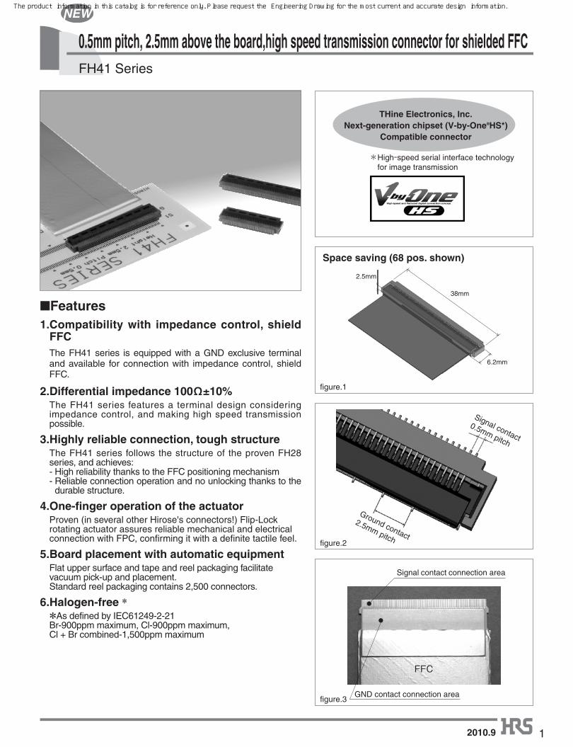
Signal contact connection area
GND contact connection area
FFC
Space saving (68 pos. shown)
Signal contact
0.5mm pitch
Ground contact
2.5mm pitch
figure.1
figure.2
figure.3
The product information in this catalog is for reference only. Please request the Engineering Drawing for the most current and accurate design information.
2
FH41 Series●0.5mm pitch, 2.5mm above the board,high speed transmission connector for shielded FFC
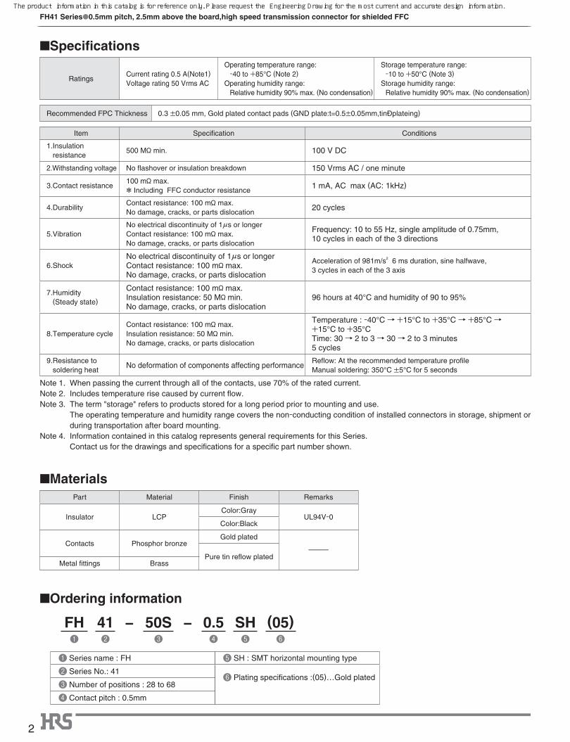
■Specifications
RatingsCurrent rating 0.5 A(Note1)Voltage rating 50 Vrms AC
O perating temperature range: -40 to +85°C (Note 2)
O perating humidity range: Relative humidity 90% max. (No condensation)
S torage temperature range: -10 to +50°C (Note 3)
S torage humidity range: Relative humidity 90% max. (No condensation)
Recommended FPC Thickness 0.3 ±0.05 mm, Gold plated contact pads (GND plate:t=0.5±0.05mm,tin plateing)
Item Specification Conditions
1. Insulation resistance
500 Mø min. 100 V DC
2.Withstanding voltage No flashover or insulation breakdown 150 Vrms AC / one minute
3.Contact resistance100 mø max.* Including FFC conductor resistance
1 mA, AC max (AC: 1kHz)
4.DurabilityContact resistance: 100 mø max.No damage, cracks, or parts dislocation
20 cycles
5.VibrationNo electrical discontinuity of 1μs or longerContact resistance: 100 mø max.No damage, cracks, or parts dislocation
Frequency: 10 to 55 Hz, single amplitude of 0.75mm, 10 cycles in each of the 3 directions
6.ShockNo electrical discontinuity of 1μs or longerContact resistance: 100 mø max.No damage, cracks, or parts dislocation
Acceleration of 981m/s2 6 ms duration, sine halfwave,3 cycles in each of the 3 axis
7.Humidity (Steady state)
Contact resistance: 100 mø max.Insulation resistance: 50 Mø min.No damage, cracks, or parts dislocation
96 hours at 40°C and humidity of 90 to 95%
8.Temperature cycleContact resistance: 100 mø max.Insulation resistance: 50 Mø min.No damage, cracks, or parts dislocation
Temperature : -40°C→ +15°C to +35°C→ +85°C→ +15°C to +35°CTime: 30→ 2 to 3→ 30→ 2 to 3 minutes5 cycles
9. Resistance to soldering heat
No deformation of components affecting performanceReflow: At the recommended temperature profileManual soldering: 350°C ±5°C for 5 seconds
Note 1. When passing the current through all of the contacts, use 70% of the rated current.Note 2. Includes temperature rise caused by current flow.Note 3. The term "storage" refers to products stored for a long period prior to mounting and use. The operating temperature and humidity range covers the non-conducting condition of installed connectors in storage, shipment or
during transportation after board mounting.Note 4. Information contained in this catalog represents general requirements for this Series. Contact us for the drawings and specifications for a specific part number shown.
■MaterialsPart Material Finish Remarks
Insulator LCPColor:Gray
UL94V-0Color:Black
Contacts Phosphor bronzeGold plated
---------Pure tin reflow plated
Metal fittings Brass
■Ordering information
FH 41 − 50S − 0.5 SH (05)❶ ❷ ❸ ❹ ❺ ❻
❺ SH : SMT horizontal mounting type
❻ Plating specifications :(05)…Gold plated
❶ Series name : FH
❷ Series No.: 41
❸ Number of positions : 28 to 68
❹ Contact pitch : 0.5mm
The product information in this catalog is for reference only. Please request the Engineering Drawing for the most current and accurate design information.
3
FH41 Series●0.5mm pitch, 2.5mm above the board,high speed transmission connector for shielded FFC
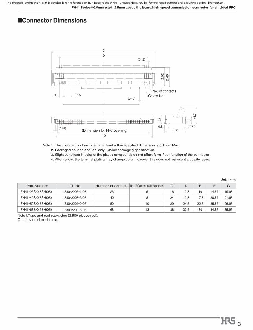
■Connector Dimensions
(5.4
5)
G
(5.0
5)
(0.12)
(0.12)
1
E
D
C
(0.15)
2.5
(Dimension for FFC opening)
No. of contactsCavity No.
6.2
2.5
0.8 0.25
2
(4.7
)
� Unit : mm
Part Number CL No. Number of contacts No. of Contacts(GND contacts) C D E F G
FH41-28S-0.5SH(05) 580-2208-1-05 28 5 18 13.5 10 14.57 15.95
FH41-40S-0.5SH(05) 580-2205-3-05 40 8 24 19.5 17.5 20.57 21.95
FH41-50S-0.5SH(05) 580-2204-0-05 50 10 29 24.5 22.5 25.57 26.95
FH41-68S-0.5SH(05) 580-2202-5-05 68 13 38 33.5 30 34.57 35.95
Note1.Tape and reel packaging (2,500 pieces/reel).Order by number of reels.
Note 1. The coplanarity of each terminal lead within specified dimension is 0.1 mm Max. 2. Packaged on tape and reel only. Check packaging specification. 3. Slight variations in color of the plastic compounds do not affect form, fit or function of the connector. 4. After reflow, the terminal plating may change color, however this does not represent a quality issue.
The product information in this catalog is for reference only. Please request the Engineering Drawing for the most current and accurate design information.
4
FH41 Series●0.5mm pitch, 2.5mm above the board,high speed transmission connector for shielded FFC
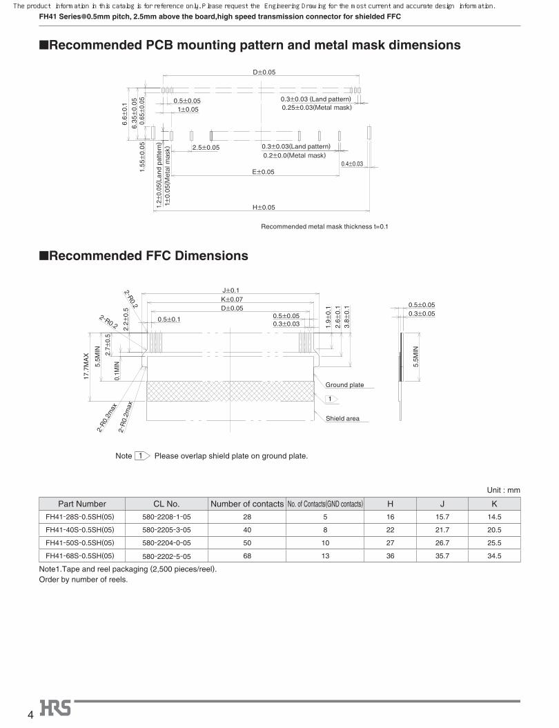
■Recommended PCB mounting pattern and metal mask dimensions
■Recommended FFC Dimensions
1±0.050.5±0.05
2.5±0.05
0.3±0.03 (Land pattern)
0.3±0.03(Land pattern)
0.4±0.03E±0.05
D±0.05
H±0.05
6.6±
0.1
0.65
±0.
05
1.2±
0.05
(Lan
d pa
tter
n)
1.55
±0.
05
6.3
5±0.
05
0.2±0.0(Metal mask)1±
0.0
5(Metal mask)
0.25±0.03(Metal mask)
Recommended metal mask thickness t=0.1
Please overlap shield plate on ground plate.Note
Shield area
Ground plate
17.7
MA
X
0.5±0.050.3±0.05
5.5M
IN
3.8±
0.1
2.6±
0.1
1.9±
0.1
5.5M
IN
0.1M
IN2.
7±0.
5
2.2±
0.5
0.5±0.1 0.5±0.050.3±0.03
J±0.1K±0.07D±0.05
2-R
0.2m
ax
2-R
0.2m
ax
2-R0.2
2-R0.2
1
1
� Unit : mm
Part Number CL No. Number of contacts No. of Contacts(GND contacts) H J K
FH41-28S-0.5SH(05) 580-2208-1-05 28 5 16 15.7 14.5
FH41-40S-0.5SH(05) 580-2205-3-05 40 8 22 21.7 20.5
FH41-50S-0.5SH(05) 580-2204-0-05 50 10 27 26.7 25.5
FH41-68S-0.5SH(05) 580-2202-5-05 68 13 36 35.7 34.5
Note1.Tape and reel packaging (2,500 pieces/reel).Order by number of reels.
The product information in this catalog is for reference only. Please request the Engineering Drawing for the most current and accurate design information.
5
FH41 Series●0.5mm pitch, 2.5mm above the board,high speed transmission connector for shielded FFC
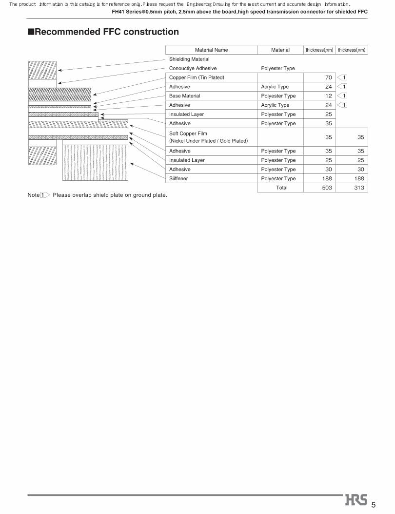
■Recommended FFC construction
Note 1 Please overlap shield plate on ground plate.
Material Name Material thickness(μm) thickness(μm)
Shielding Material
Conouctiye Adhesive Polyester Type
Copper Film (Tin Plated) 70Adhesive Acrylic Type 24Base Material Polyester Type 12Adhesive Acrylic Type 24Insulated Layer Polyester Type 25Adhesive Polyester Type 35
Soft Copper Film
(Nickel Under Plated / Gold Plated) 35 35
Adhesive Polyester Type 35 35Insulated Layer Polyester Type 25 25Adhesive Polyester Type 30 30Siiffener Polyester Type 188 188
Total 503 313
1
1
1
1
The product information in this catalog is for reference only. Please request the Engineering Drawing for the most current and accurate design information.
6
FH41 Series●0.5mm pitch, 2.5mm above the board,high speed transmission connector for shielded FFC
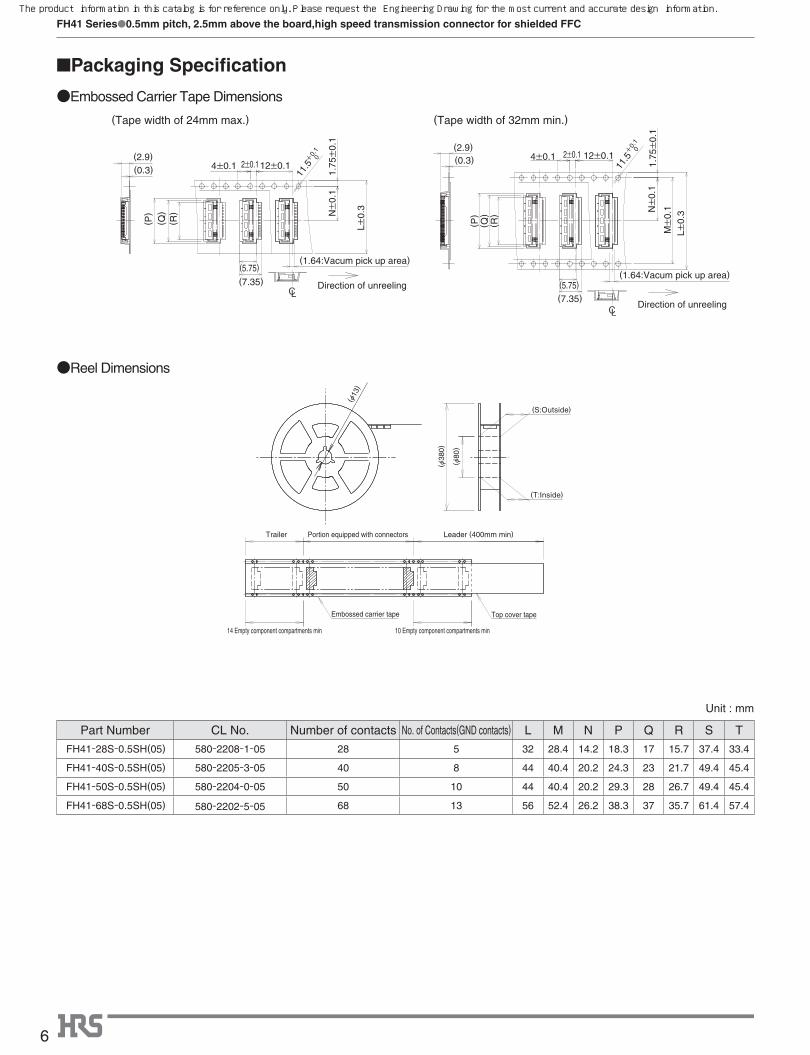
●Embossed Carrier Tape Dimensions
■Packaging Specification
●Reel Dimensions
LC
CL
(Tape width of 32mm min.)(Tape width of 24mm max.)
Direction of unreeling
Direction of unreeling
(Q)
(1.64:Vacum pick up area)
(P)
4±0.1 2±0.1 12±0.1(0.3)(2.9)
(R)
L±0.
3M
±0.
1
1.75
±0.
1
(7.35)(5.75)
N±
0.1
(5.75)
(7.35)
1.75
±0.
1
L±0.
3
(R)
(2.9)(0.3) 12±0.12±0.14±0.1
(P)
(1.64:Vacum pick up area)
(Q) N±
0.1
11.5
0+0.
1
11.5
0+0.
1
Trailer Portion equipped with connectors
Embossed carrier tape
Leader (400mm min)
Top cover tape
10 Empty component compartments min14 Empty component compartments min
(Ø13
)
(Ø80
)
(Ø38
0)
(S:Outside)
(T:Inside)
� Unit : mm
Part Number CL No. Number of contacts No. of Contacts(GND contacts) L M N P Q R S T
FH41-28S-0.5SH(05) 580-2208-1-05 28 5 32 28.4 14.2 18.3 17 15.7 37.4 33.4
FH41-40S-0.5SH(05) 580-2205-3-05 40 8 44 40.4 20.2 24.3 23 21.7 49.4 45.4
FH41-50S-0.5SH(05) 580-2204-0-05 50 10 44 40.4 20.2 29.3 28 26.7 49.4 45.4
FH41-68S-0.5SH(05) 580-2202-5-05 68 13 56 52.4 26.2 38.3 37 35.7 61.4 57.4
The product information in this catalog is for reference only. Please request the Engineering Drawing for the most current and accurate design information.
7
FH41 Series●0.5mm pitch, 2.5mm above the board,high speed transmission connector for shielded FFC
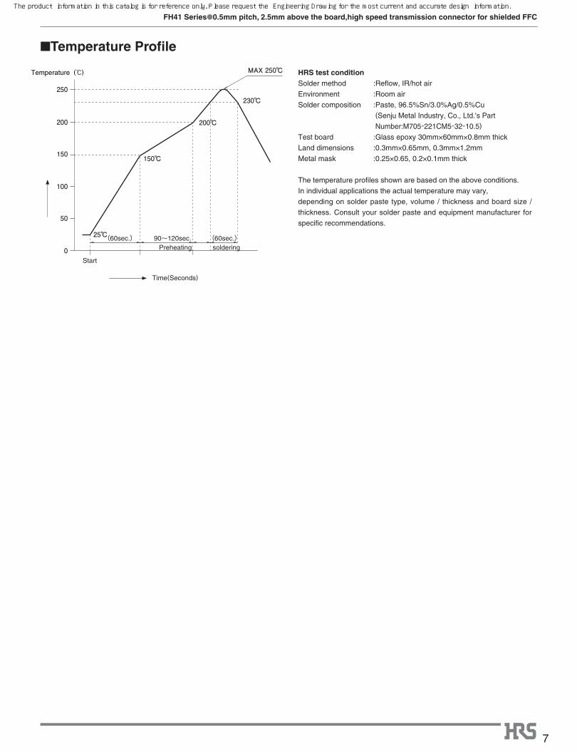
■Temperature Profile
HRS test conditionSolder method :Reflow, IR/hot air
Environment :Room air
Solder composition :Paste, 96.5%Sn/3.0%Ag/0.5%Cu
(Senju Metal Industry, Co., Ltd.'s Part
Number:M705-221CM5-32-10.5)
Test board :Glass epoxy 30mm×60mm×0.8mm thick
Land dimensions :0.3mm×0.65mm, 0.3mm×1.2mm
Metal mask :0.25×0.65, 0.2×0.1mm thick
The temperature profiles shown are based on the above conditions.
In individual applications the actual temperature may vary,
depending on solder paste type, volume / thickness and board size /
thickness. Consult your solder paste and equipment manufacturer for
specific recommendations.
MAX 250℃
Start
Time(Seconds)
25℃(60sec.) (60sec.)90~120sec.Preheating soldering0
50
100
150 150℃
200℃
230℃
200
250
Temperature (ç)
The product information in this catalog is for reference only. Please request the Engineering Drawing for the most current and accurate design information.
8
FH41 Series●0.5mm pitch, 2.5mm above the board,high speed transmission connector for shielded FFC
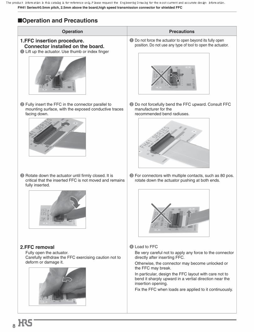
Operation Precautions
1. FFC insertion procedure. Connector installed on the board.
❶ Lift up the actuator. Use thumb or index finger
❶ Do not force the actuator to open beyond its fully open position. Do not use any type of tool to open the actuator.
❷ Fully insert the FFC in the connector parallel to mounting surface, with the exposed conductive traces facing down.
❷ Do not forcefully bend the FFC upward. Consult FFC manufacturer for the recommended bend radiuses.
❸ Rotate down the actuator until firmly closed. It is critical that the inserted FFC is not moved and remains fully inserted.
❸ For connectors with multiple contacts, such as 80 pos. rotate down the actuator pushing at both ends.
2.FFC removal Fully open the actuator.
Carefully withdraw the FFC exercising caution not to deform or damage it.
❹ Load to FFC Be very careful not to apply any force to the connector
directly after inserting FFC. Otherwise, the connector may become unlocked or
the FFC may break. In particular, design the FFC layout with care not to
bend it sharply upward in a vertial direction near the insertion opening.
Fix the FFC when loads are applied to it continuously.
■Operation and Precautions
110°
The product information in this catalog is for reference only. Please request the Engineering Drawing for the most current and accurate design information.
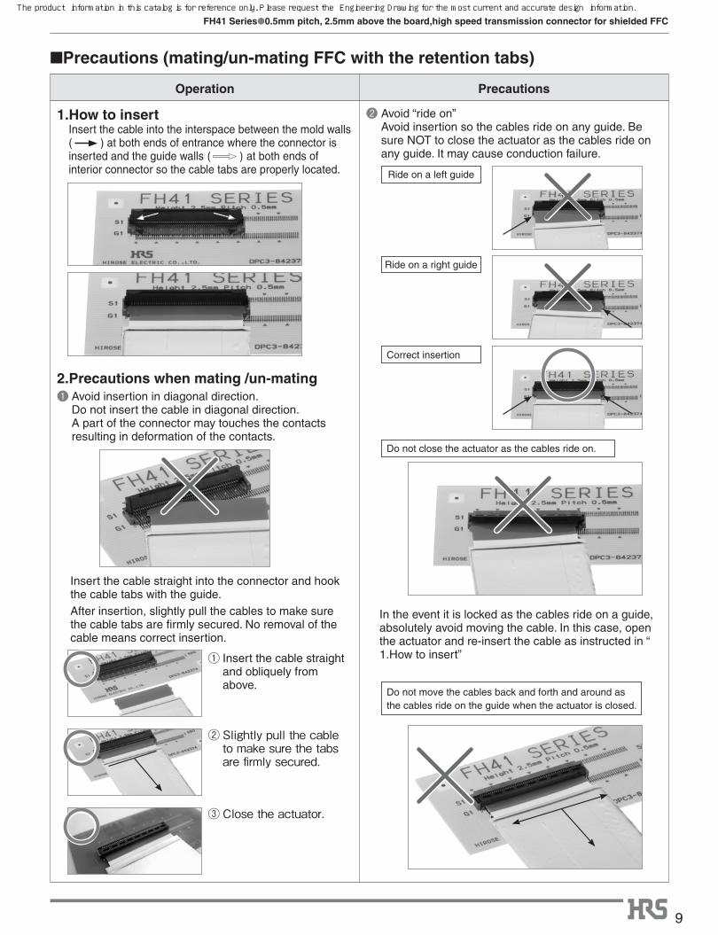
① �Insert the cable straight and obliquely from above.
② �Slightly�pull�the�cable�to�make�sure�the�tabs�are�firmly�secured.
③ Close�the�actuator.
Ride on a left guide
Ride on a right guide
Correct insertion
Do not close the actuator as the cables ride on.
Do not move the cables back and forth and around as the cables ride on the guide when the actuator is closed.
9
FH41 Series●0.5mm pitch, 2.5mm above the board,high speed transmission connector for shielded FFC
Operation Precautions
1. How to insertInsert the cable into the interspace between the mold walls ( ) at both ends of entrance where the connector is inserted and the guide walls�( )�at both ends of interior connector so the cable tabs are properly located.
❷ Avoid “ride on” Avoid insertion so the cables ride on any guide. Be sure NOT to close the actuator as the cables ride on any guide. It may cause conduction failure.
2. Precautions when mating /un-mating ❶ �Avoid insertion in diagonal direction.
Do not insert the cable in diagonal direction. A part of the connector may touches the contacts resulting in deformation of the contacts.
�
Insert the cable straight into the connector and hook the cable tabs with the guide. After insertion, slightly pull the cables to make sure the cable tabs are firmly secured. No removal of the cable means correct insertion.
In the event it is locked as the cables ride on a guide, absolutely avoid moving the cable. In this case, open the actuator and re-insert the cable as instructed in “ 1.How to insert”
■Precautions (mating/un-mating FFC with the retention tabs)
The product information in this catalog is for reference only. Please request the Engineering Drawing for the most current and accurate design information.