Embed Size (px)
Citation preview
Confidential 1 © Nokia Siemens Networks RN31576EN30GLA0
Capacity Enhancement3G RANOP RU30
Confidential 2 © Nokia Siemens Networks RN31576EN30GLA0
Course Content
KPI overviewPerformance monitoringAir interface optimizationTraffic MonitoringCapacity Enhancement
Confidential 3 © Nokia Siemens Networks RN31576EN30GLA0
Module ObjectivesAt the end of the module you will be able to:• Describe capacity enhancing R99 features
• Discuss the impact of R5 and R6 HSPA features on capacity
• Demonstrate the capacity enhancement potentials of HSPA features introduced with R7 and beyond
Confidential 4 © Nokia Siemens Networks RN31576EN30GLA0
R99 Features
AMR
BLER target settings
Eb/No settings
Throughput based optimization
Maximum radio link power
4Rx diversity
HSDPA
HSUPA
HSDPA+
HSUPA+
Capacity Enhancement
Confidential 5 © Nokia Siemens Networks RN31576EN30GLA0
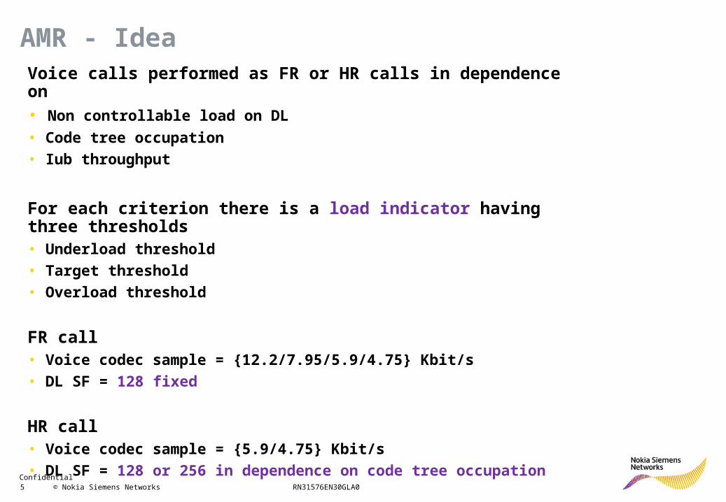
Voice calls performed as FR or HR calls in dependence on• Non controllable load on DL
• Code tree occupation
• Iub throughput
For each criterion there is a load indicator having three thresholds• Underload threshold
• Target threshold
• Overload threshold
FR call• Voice codec sample = {12.2/7.95/5.9/4.75} Kbit/s
• DL SF = 128 fixed
HR call• Voice codec sample = {5.9/4.75} Kbit/s
• DL SF = 128 or 256 in dependence on code tree occupation
AMR - Idea
Confidential 6 © Nokia Siemens Networks RN31576EN30GLA0
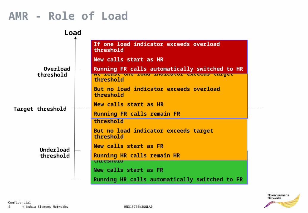
AMR - Role of LoadLoad
Underload thresholdIf no load indicator exceeds underload threshold
New calls start as FR
Running HR calls automatically switched to FR
If no load indicator exceeds underload threshold
New calls start as FR
Running HR calls automatically switched to FR
At least one load indicator exceeds underload threshold
But no load indicator exceeds target threshold
New calls start as FR
Running HR calls remain HR
At least one load indicator exceeds underload threshold
But no load indicator exceeds target threshold
New calls start as FR
Running HR calls remain HR
Target threshold
At least one load indicator exceeds target threshold
But no load indicator exceeds overload threshold
New calls start as HR
Running FR calls remain FR
At least one load indicator exceeds target threshold
But no load indicator exceeds overload threshold
New calls start as HR
Running FR calls remain FR
Overload threshold
If one load indicator exceeds overload threshold
New calls start as HR
Running FR calls automatically switched to HR
If one load indicator exceeds overload threshold
New calls start as HR
Running FR calls automatically switched to HR
Confidential 7 © Nokia Siemens Networks RN31576EN30GLA0
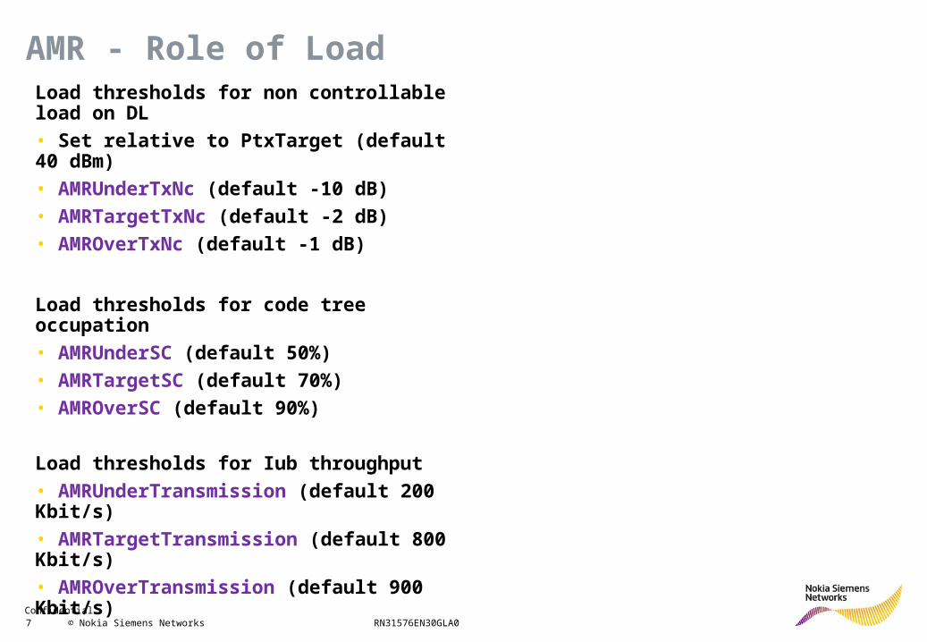
AMR - Role of LoadLoad thresholds for non controllable load on DL
• Set relative to PtxTarget (default 40 dBm)
• AMRUnderTxNc (default -10 dB)
• AMRTargetTxNc (default -2 dB)
• AMROverTxNc (default -1 dB)
Load thresholds for code tree occupation
• AMRUnderSC (default 50%)
• AMRTargetSC (default 70%)
• AMROverSC (default 90%)
Load thresholds for Iub throughput
• AMRUnderTransmission (default 200 Kbit/s)
• AMRTargetTransmission (default 800 Kbit/s)
• AMROverTransmission (default 900 Kbit/s)
Confidential 8 © Nokia Siemens Networks RN31576EN30GLA0
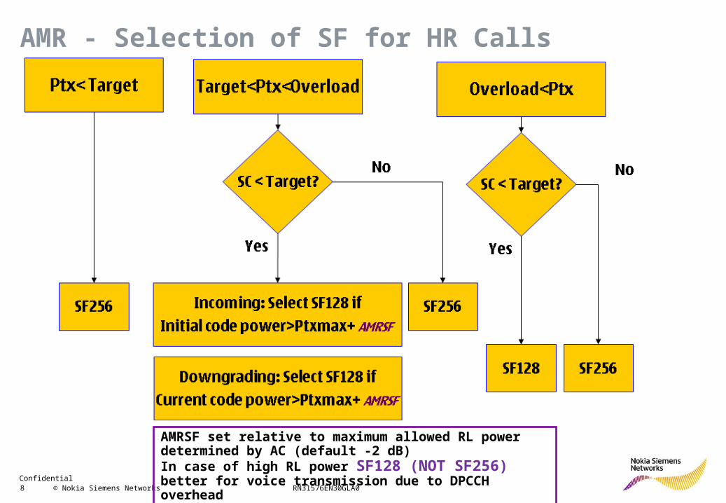
AMR - Selection of SF for HR Calls
AMRSF set relative to maximum allowed RL power determined by AC (default -2 dB)In case of high RL power SF128 (NOT SF256) better for voice transmission due to DPCCH overhead
Confidential 9 © Nokia Siemens Networks RN31576EN30GLA0
For R99 bearers the operator can define the BLER target controlled by outer loop power control
Strict BLER target (low BLER)• Little throughput degradation and delay by re-transmission → good quality for user
• But higher Eb/No needed → higher power consumption per radio link
Less strict BLER target (high BLER)• Strong throughput degradation and delay by re-transmission → bad quality for user
• But less Eb/No needed → lower power consumption per radio link
BLER Target Settings - Idea
Confidential 10 © Nokia Siemens Networks RN31576EN30GLA0
BLER target can be defined for the following services• SRB of 3.4 and 13.6 Kbit/s (EbNoDCHOfSRB34/136Qua, default 1%)
• Narrowband and wideband AMR (EbNoDCHOfCSN/WBAMRQua, default 1%)
• Streaming service
• NRT service
In case of streaming and NRT service one can define two BLER targets• Strict target for low bit rate up to 64 Kbit/s (EbNoDCHOfPSStr/NRTPriQua, default = 1%)
• Less strict target for high bit rate > 64 Kbit/s (EbNoDCHOfPSStr/NRTSecQua, default = 5%)
• One can select per bit rate, which of the two BLER targets shall be used
BLER Target Settings - Role of Service
Confidential 11 © Nokia Siemens Networks RN31576EN30GLA0
BLER Target Settings - Example
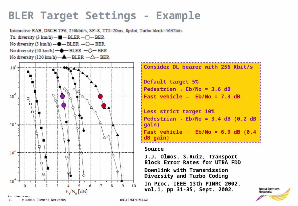
Consider DL bearer with 256 Kbit/s
Default target 5%Pedestrian → Eb/No = 3.6 dBFast vehicle → Eb/No = 7.3 dB
Less strict target 10%Pedestrian → Eb/No = 3.4 dB (0.2 dB gain)Fast vehicle → Eb/No = 6.9 dB (0.4 dB gain)
Source
J.J. Olmos, S.Ruiz, Transport Block Error Rates for UTRA FDD
Downlink with Transmission Diversity and Turbo Coding
In Proc. IEEE 13th PIMRC 2002, vol.1, pp 31-35, Sept. 2002.
Confidential 12 © Nokia Siemens Networks RN31576EN30GLA0
BLER Target Settings - Example
RW
NEi b
DL /
/])1[( 0
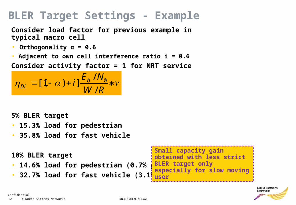
Consider load factor for previous example in typical macro cell• Orthogonality α = 0.6
• Adjacent to own cell interference ratio i = 0.6
Consider activity factor = 1 for NRT service
5% BLER target
• 15.3% load for pedestrian
• 35.8% load for fast vehicle
10% BLER target
• 14.6% load for pedestrian (0.7% gain)
• 32.7% load for fast vehicle (3.1% gain)
Small capacity gain obtained with less strict BLER target only especially for slow moving user
Confidential 13 © Nokia Siemens Networks RN31576EN30GLA0
For R99 and HSUPA bearers the operator can define Eb/No values as well• Eb/No settings cannot be treated as independent configuration, as Eb/No affects BLER
• Eb/No settings offered by NSN applied to initial radio link power only
• Afterwards Eb/No adjusted by outer loop power control to follow BLER target
• Thus Eb/No settings affect setup and access only, but not load in the network
High initial Eb/No• High initial radio link power → high blocking probability
• But low initial BLER → low risk of drop during initial phase
Low initial Eb/No• Low initial radio link power → low blocking probability
• But high initial BLER → high risk of drop during initial phase
Eb/No Settings - Restrictions
Confidential 14 © Nokia Siemens Networks RN31576EN30GLA0
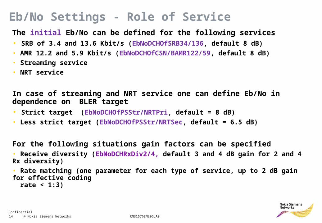
The initial Eb/No can be defined for the following services• SRB of 3.4 and 13.6 Kbit/s (EbNoDCHOfSRB34/136, default 8 dB)
• AMR 12.2 and 5.9 Kbit/s (EbNoDCHOfCSN/BAMR122/59, default 8 dB)
• Streaming service
• NRT service
In case of streaming and NRT service one can define Eb/No in dependence on BLER target• Strict target (EbNoDCHOfPSStr/NRTPri, default = 8 dB)
• Less strict target (EbNoDCHOfPSStr/NRTSec, default = 6.5 dB)
For the following situations gain factors can be specified• Receive diversity (EbNoDCHRxDiv2/4, default 3 and 4 dB gain for 2 and 4 Rx diversity)
• Rate matching (one parameter for each type of service, up to 2 dB gain for effective coding rate < 1:3)
Eb/No Settings - Role of Service
Confidential 15 © Nokia Siemens Networks RN31576EN30GLA0
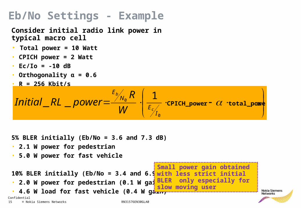
Consider initial radio link power in typical macro cell• Total power = 10 Watt
• CPICH power = 2 Watt
• Ec/Io = -10 dB
• Orthogonality α = 0.6
• R = 256 Kbit/s
5% BLER initially (Eb/No = 3.6 and 7.3 dB)
• 2.1 W power for pedestrian
• 5.0 W power for fast vehicle
10% BLER initially (Eb/No = 3.4 and 6.9 dB)
• 2.0 W power for pedestrian (0.1 W gain)
• 4.6 W load for fast vehicle (0.4 W gain)
Eb/No Settings - Example
rtotal_powerCPICH_powe
0
01
__I
E
NE
c
b
W
RpowerRLInitial
Small power gain obtained with less strict initial BLER only especially for slow moving user
Confidential 16 © Nokia Siemens Networks RN31576EN30GLA0
Consider NRT DCH of low utilization• Inactivity timers do not expire in case of frequent transmission of small packets
• Huge amount of resources might be reserved unnecessarily • Code of low SF (blocks many codes of high SF)
• Channel elements
• Iub resources
Throughput based optimization• Downgrade DCH to lower level in this case
• Can be enabled for each NRT traffic class individually• Inactive with traffic handling priority 1/2/3
• Background
Throughput Based Optimization - Idea
Confidential 17 © Nokia Siemens Networks RN31576EN30GLA0
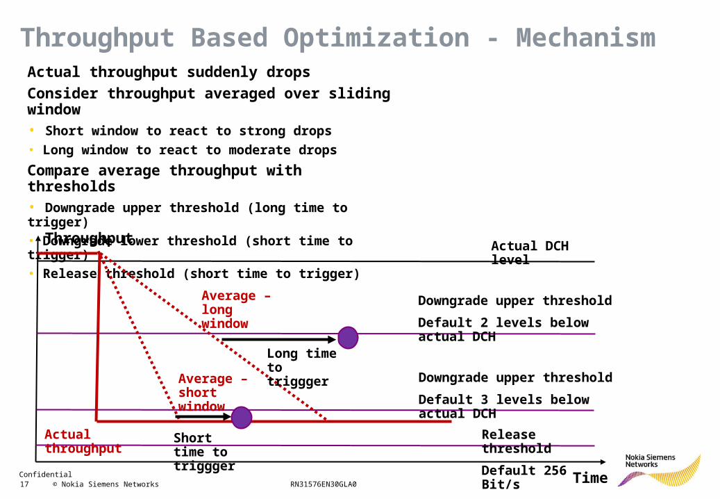
Actual throughput suddenly drops
Consider throughput averaged over sliding window• Short window to react to strong drops
• Long window to react to moderate drops
Compare average throughput with thresholds• Downgrade upper threshold (long time to trigger)
• Downgrade lower threshold (short time to trigger)
• Release threshold (short time to trigger)
Throughput Based Optimization - Mechanism
Actual DCH level
Downgrade upper threshold
Default 2 levels below actual DCH
Downgrade upper threshold
Default 3 levels below actual DCH
Release threshold
Default 256 Bit/s
Actual throughput
Average – long window
Average – short window
Short time to triggger
Long time to triggger
Time
Throughput
Confidential 18 © Nokia Siemens Networks RN31576EN30GLA0
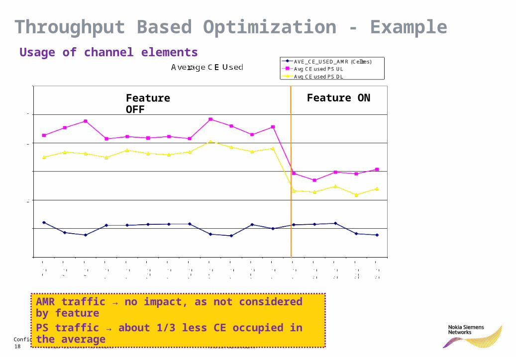
Throughput Based Optimization - Example
AMR traffic → no impact, as not considered by featurePS traffic → about 1/3 less CE occupied in the average
Feature OFF Feature ON
Usage of channel elements
Confidential 19 © Nokia Siemens Networks RN31576EN30GLA0
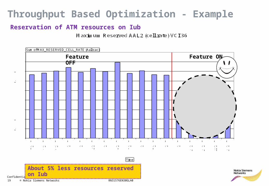
Throughput Based Optimization - Example
Feature OFF Feature ON
About 5% less resources reserved on Iub
Reservation of ATM resources on Iub
Confidential 20 © Nokia Siemens Networks RN31576EN30GLA0
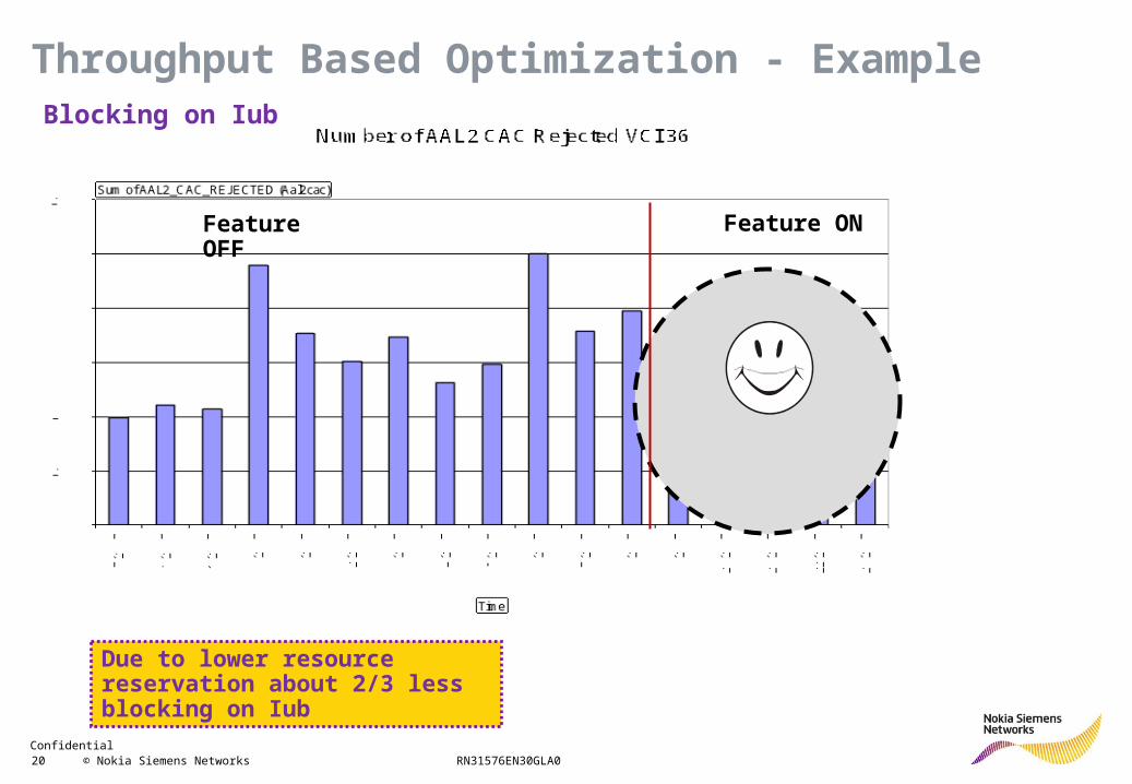
Throughput Based Optimization - Example
Feature OFF Feature ON
Due to lower resource reservation about 2/3 less blocking on Iub
Blocking on Iub
Confidential 21 © Nokia Siemens Networks RN31576EN30GLA0
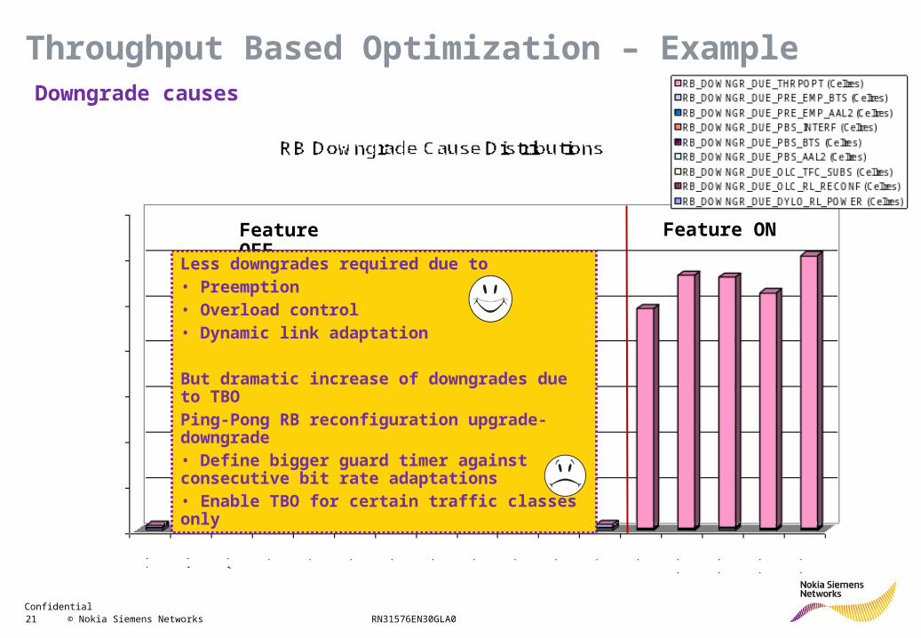
Throughput Based Optimization – Example
Feature OFF Feature ON
Less downgrades required due to• Preemption• Overload control• Dynamic link adaptation
But dramatic increase of downgrades due to TBOPing-Pong RB reconfiguration upgrade-downgrade• Define bigger guard timer against consecutive bit rate adaptations• Enable TBO for certain traffic classes only
Downgrade causes
Confidential 22 © Nokia Siemens Networks RN31576EN30GLA0
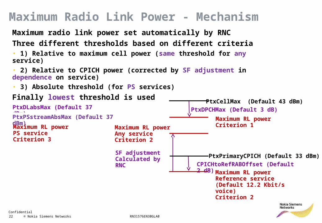
Maximum Radio Link Power - MechanismMaximum radio link power set automatically by RNC
Three different thresholds based on different criteria• 1) Relative to maximum cell power (same threshold for any service)
• 2) Relative to CPICH power (corrected by SF adjustment in dependence on service)
• 3) Absolute threshold (for PS services)
Finally lowest threshold is used
PtxDPCHMax (Default 3 dB)
CPICHtoRefRABOffset (Default 2 dB)
PtxCellMax (Default 43 dBm)
Maximum RL power Criterion 1
PtxDLabsMax (Default 37 dBm)
PtxPSstreamAbsMax (Default 37 dBm)
PtxPrimaryCPICH (Default 33 dBm)
Maximum RL power Reference service (Default 12.2 Kbit/s voice) Criterion 2
SF adjustmentCalculated by RNC
Maximum RL power Any service Criterion 2
Maximum RL power PS service Criterion 3
Confidential 23 © Nokia Siemens Networks RN31576EN30GLA0
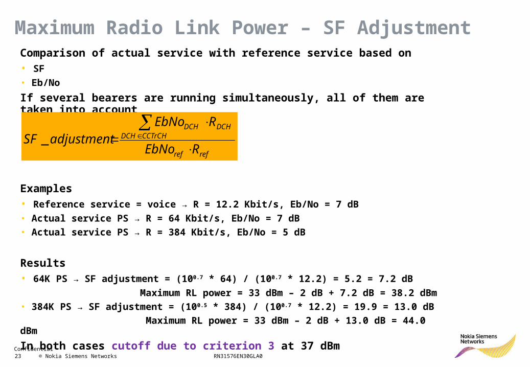
Comparison of actual service with reference service based on• SF
• Eb/No
If several bearers are running simultaneously, all of them are taken into account
Examples• Reference service = voice → R = 12.2 Kbit/s, Eb/No = 7 dB
• Actual service PS → R = 64 Kbit/s, Eb/No = 7 dB
• Actual service PS → R = 384 Kbit/s, Eb/No = 5 dB
Results• 64K PS → SF adjustment = (100.7 * 64) / (100.7 * 12.2) = 5.2 = 7.2 dB
Maximum RL power = 33 dBm – 2 dB + 7.2 dB = 38.2 dBm
• 384K PS → SF adjustment = (100.5 * 384) / (100.7 * 12.2) = 19.9 = 13.0 dB
Maximum RL power = 33 dBm – 2 dB + 13.0 dB = 44.0 dBm
In both cases cutoff due to criterion 3 at 37 dBm
refref
CCTrCHDCHDCHDCH
REbNo
REbNoadjustmentSF
_
Maximum Radio Link Power – SF Adjustment
Confidential 24 © Nokia Siemens Networks RN31576EN30GLA0
CPICHtoRefRABOffset• Maximum power of reference service relative to CPICH power
• Shifts all services to higher or lower maximum radio link power
• Low power for reference service• Low coverage in general
• But higher capacity, as no single user can take away too much power
• High power for reference service• High coverage in general
• But lower capacity, as single user can take away much power
PtxDLAbsMax / PtxPSstreamAbsMax• Maximum power of NRT / RT PS service
• Cutoff to avoid, that single user takes too much power
• Similar compromise between coverage and capacity needed as for CPICHtoRefRABOffset
Maximum Radio Link Power – Key Parameters
Confidential 25 © Nokia Siemens Networks RN31576EN30GLA0
BTS
UE
384kbps 128kbps
distance
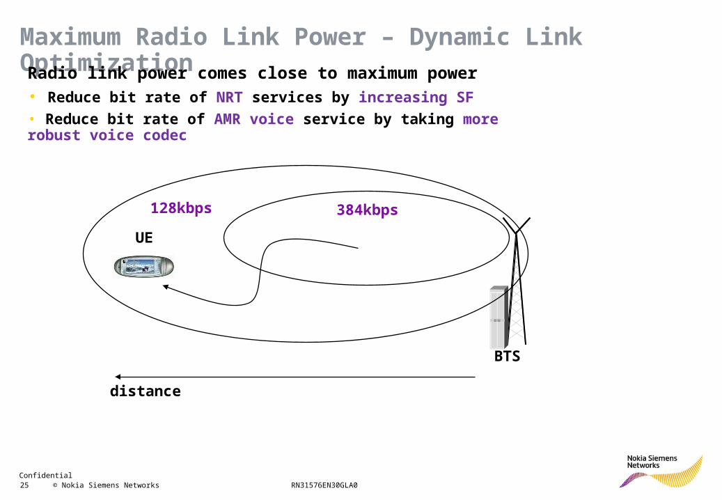
Maximum Radio Link Power – Dynamic Link Optimization
Radio link power comes close to maximum power• Reduce bit rate of NRT services by increasing SF
• Reduce bit rate of AMR voice service by taking more robust voice codec
Confidential 26 © Nokia Siemens Networks RN31576EN30GLA0
time
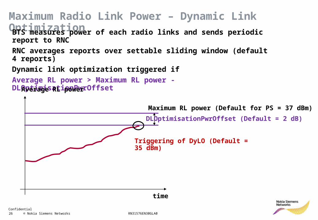
Triggering of DyLO (Default = 35 dBm)
DLOptimisationPwrOffset (Default = 2 dB)
Maximum Radio Link Power – Dynamic Link Optimization
BTS measures power of each radio links and sends periodic report to RNC
RNC averages reports over settable sliding window (default 4 reports)
Dynamic link optimization triggered if
Average RL power > Maximum RL power - DLOptimisationPwrOffset
Average RL power
Maximum RL power (Default for PS = 37 dBm)
Confidential 27 © Nokia Siemens Networks RN31576EN30GLA0
BTS
UE
384 K
distance
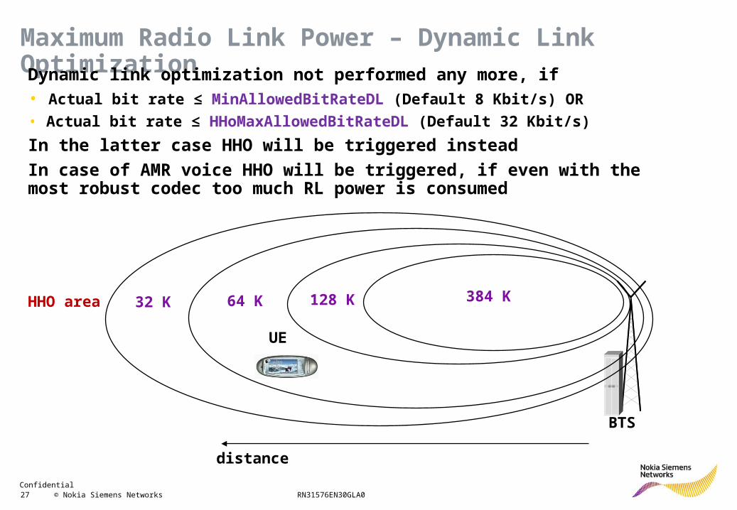
Maximum Radio Link Power – Dynamic Link Optimization
Dynamic link optimization not performed any more, if• Actual bit rate ≤ MinAllowedBitRateDL (Default 8 Kbit/s) OR
• Actual bit rate ≤ HHoMaxAllowedBitRateDL (Default 32 Kbit/s)
In the latter case HHO will be triggered instead
In case of AMR voice HHO will be triggered, if even with the most robust codec too much RL power is consumed
128 K64 K32 KHHO area
Confidential 28 © Nokia Siemens Networks RN31576EN30GLA0
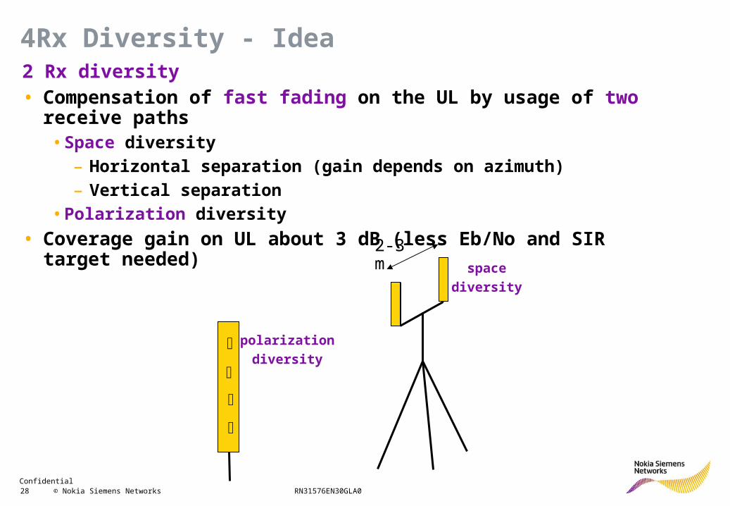
2 Rx diversity• Compensation of fast fading on the UL by usage of two receive paths
• Space diversity
– Horizontal separation (gain depends on azimuth)
– Vertical separation
• Polarization diversity
• Coverage gain on UL about 3 dB (less Eb/No and SIR target needed)
2-3 m
space
diversity
polarization
diversity
4Rx Diversity - Idea
Confidential 29 © Nokia Siemens Networks RN31576EN30GLA0
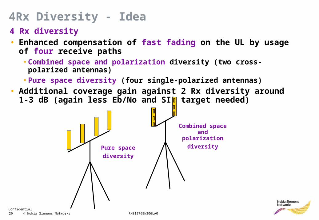
4 Rx diversity• Enhanced compensation of fast fading on the UL by usage of four
receive paths• Combined space and polarization diversity (two cross-polarized antennas)
• Pure space diversity (four single-polarized antennas)
• Additional coverage gain against 2 Rx diversity around 1-3 dB (again less Eb/No and SIR target needed)
Combined space and polarization
diversity
Pure space
diversity
4Rx Diversity - Idea
Confidential 30 © Nokia Siemens Networks RN31576EN30GLA0
• 4 Rx diversity can be realized together with the following features, defined by the following implementation phases• Phase 1 MIMO
• Phase 2 + Frequency domain equalizer
• Phase 3 + HSUPA Interference cancellation receiver
4Rx Diversity - Interoperability
Confidential 31 © Nokia Siemens Networks RN31576EN30GLA0
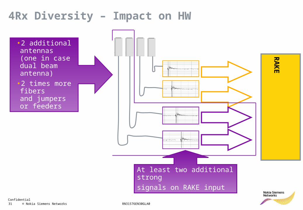
RA
KE
At least two additional strong
signals on RAKE input
•2 additional antennas (one in case dual beam antenna)
•2 times more fibers and jumpers or feeders
4Rx Diversity – Impact on HW
Confidential 32 © Nokia Siemens Networks RN31576EN30GLA0
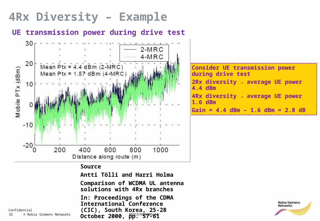
Consider UE transmission power during drive test2Rx diversity → average UE power 4.4 dBm4Rx diversity → average UE power 1.6 dBmGain = 4.4 dBm – 1.6 dBm = 2.8 dB
Source
Antti Tölli and Harri Holma
Comparison of WCDMA UL antenna solutions with 4Rx branches
In: Proceedings of the CDMA International Conference (CIC), South Korea, 25-28 October 2000, pp. 57-61
4Rx Diversity – ExampleUE transmission power during drive test
Confidential 33 © Nokia Siemens Networks RN31576EN30GLA0
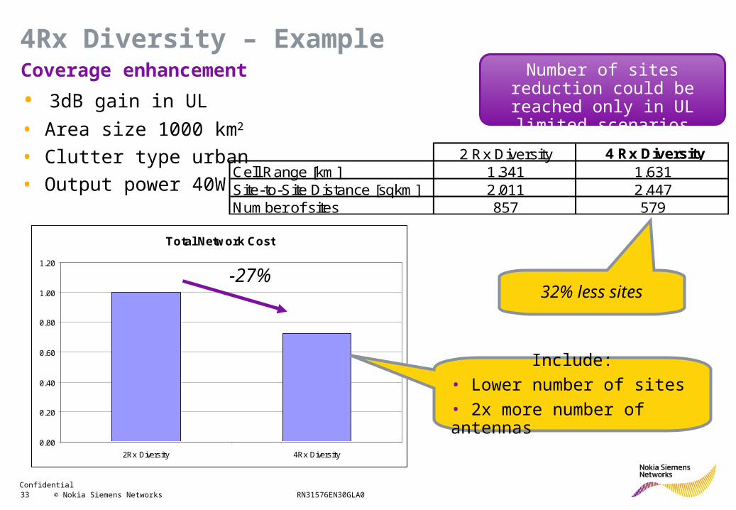
Coverage enhancement
• 3dB gain in UL
• Area size 1000 km2
• Clutter type urban
• Output power 40W
32% less sites
2 Rx Diversity 4 Rx DiversityCell Range [km] 1.341 1.631Site-to-Site Distance [sqkm] 2.011 2.447Number of sites 857 579
Number of sites reduction could be reached only in UL
limited scenarios
Total Network Cost
0.00
0.20
0.40
0.60
0.80
1.00
1.20
2Rx Diversity 4Rx Diversity
-27%
Include:
• Lower number of sites
• 2x more number of antennas
4Rx Diversity – Example
Confidential 34 © Nokia Siemens Networks RN31576EN30GLA0
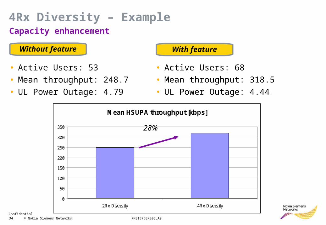
Without feature With feature
Mean HSUPA throughput [kbps]
0
50
100
150
200
250
300
350
2Rx Diversity 4Rx Diversity
28%
• Active Users: 53
• Mean throughput: 248.7
• UL Power Outage: 4.79
• Active Users: 68
• Mean throughput: 318.5
• UL Power Outage: 4.44
Capacity enhancement
4Rx Diversity – Example
Confidential 35 © Nokia Siemens Networks RN31576EN30GLA0
R99 Features
HSDPA
Fractional DPCH
Dynamic BLER
72 HSPA users per cell
HSUPA
HSDPA+
HSUPA+
Capacity Enhancement
Confidential 36 © Nokia Siemens Networks RN31576EN30GLA0
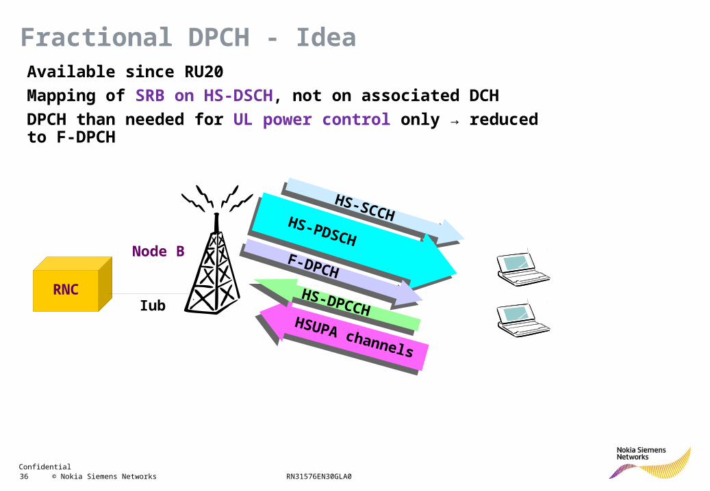
Fractional DPCH - IdeaAvailable since RU20
Mapping of SRB on HS-DSCH, not on associated DCH
DPCH than needed for UL power control only → reduced to F-DPCH
Node B
RNCIub
HS-SCCH
HS-SCCHHS - DSCH
HS-PDSCH
HSUPA channels
HSUPA channels
F-DPCH
F-DPCH
HS-DPCCH
HS-DPCCH
Confidential 37 © Nokia Siemens Networks RN31576EN30GLA0
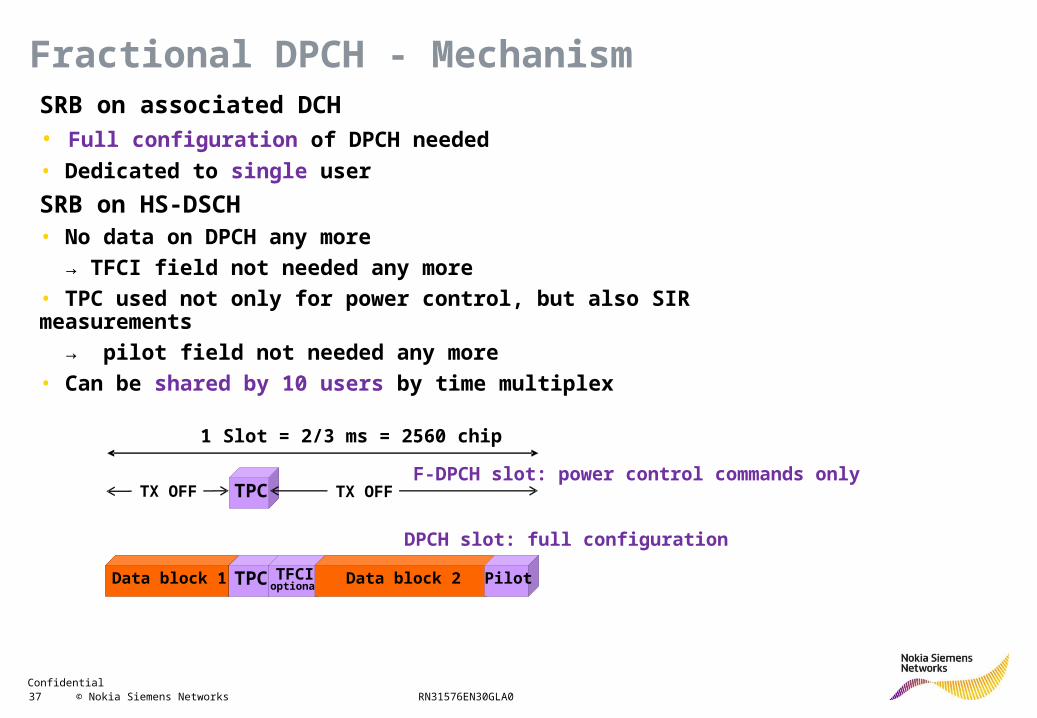
Fractional DPCH - Mechanism
Data block 1 TPC TFCIoptional
Data block 2 PilotData block 1 TPC TFCIoptional
Data block 2 Pilot
1 Slot = 2/3 ms = 2560 chip
TPCF-DPCH slot: power control commands only
DPCH slot: full configuration
TX OFF TX OFF
SRB on associated DCH• Full configuration of DPCH needed
• Dedicated to single user
SRB on HS-DSCH• No data on DPCH any more
→ TFCI field not needed any more
• TPC used not only for power control, but also SIR measurements
→ pilot field not needed any more
• Can be shared by 10 users by time multiplex
Confidential 38 © Nokia Siemens Networks RN31576EN30GLA0
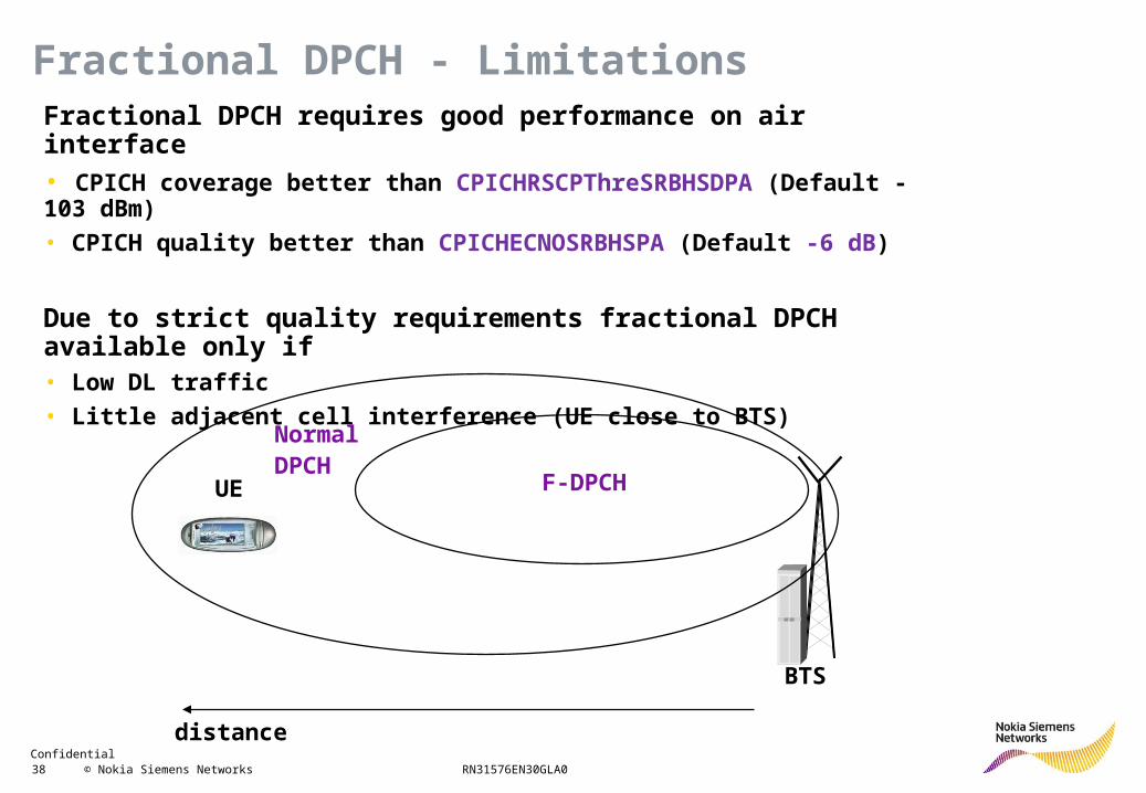
Fractional DPCH - LimitationsFractional DPCH requires good performance on air interface• CPICH coverage better than CPICHRSCPThreSRBHSDPA (Default -103 dBm)
• CPICH quality better than CPICHECNOSRBHSPA (Default -6 dB)
Due to strict quality requirements fractional DPCH available only if• Low DL traffic
• Little adjacent cell interference (UE close to BTS)
BTS
UE F-DPCH
NormalDPCH
distance
Confidential 39 © Nokia Siemens Networks RN31576EN30GLA0
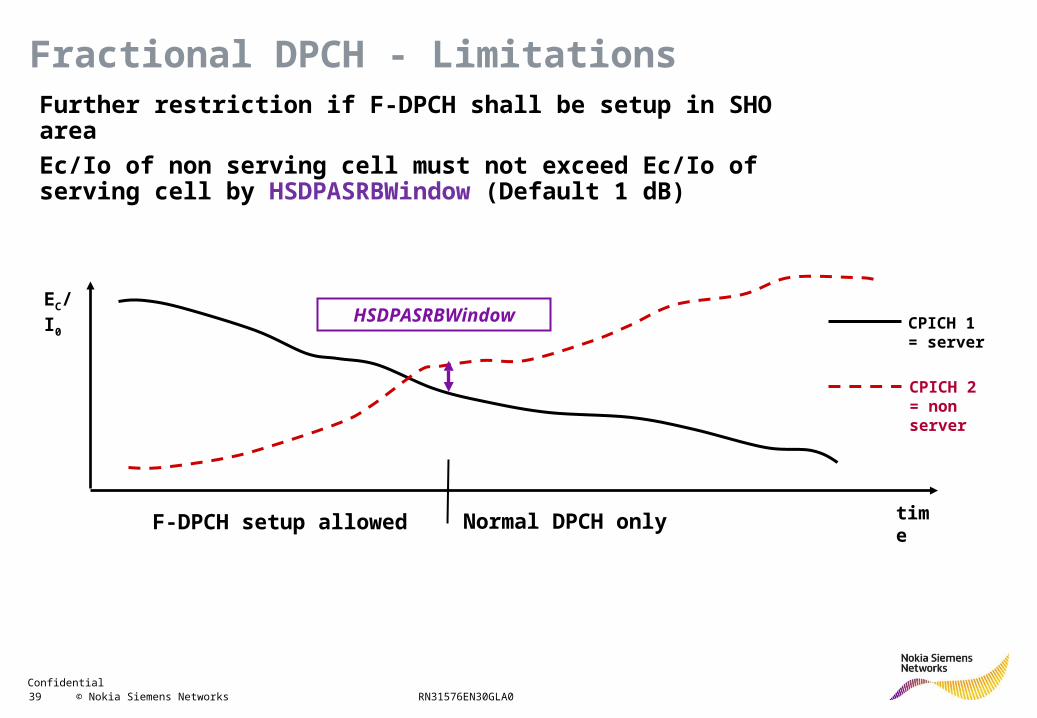
Fractional DPCH - LimitationsFurther restriction if F-DPCH shall be setup in SHO area
Ec/Io of non serving cell must not exceed Ec/Io of serving cell by HSDPASRBWindow (Default 1 dB)
CPICH 1 = server
CPICH 2 = non server
EC/I0
time
HSDPASRBWindow
F-DPCH setup allowed Normal DPCH only
Confidential 40 © Nokia Siemens Networks RN31576EN30GLA0
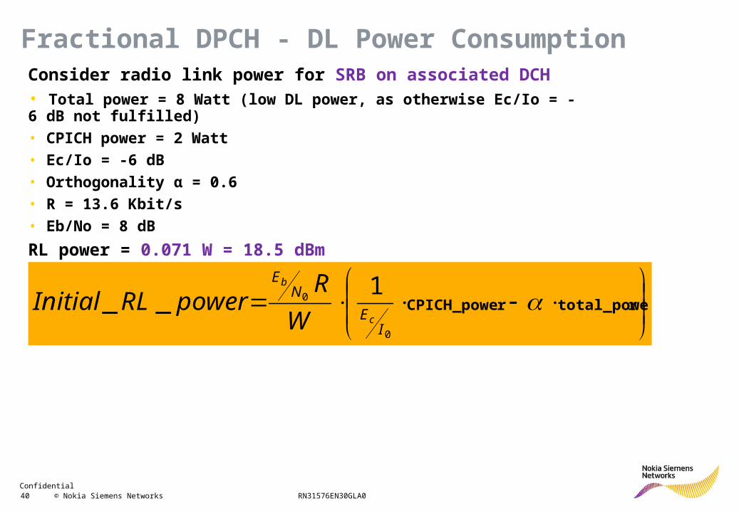
Fractional DPCH - DL Power ConsumptionConsider radio link power for SRB on associated DCH• Total power = 8 Watt (low DL power, as otherwise Ec/Io = -6 dB not fulfilled)
• CPICH power = 2 Watt
• Ec/Io = -6 dB
• Orthogonality α = 0.6
• R = 13.6 Kbit/s
• Eb/No = 8 dB
RL power = 0.071 W = 18.5 dBm
rtotal_powerCPICH_powe
0
01
__I
E
NE
c
b
W
RpowerRLInitial
Confidential 41 © Nokia Siemens Networks RN31576EN30GLA0
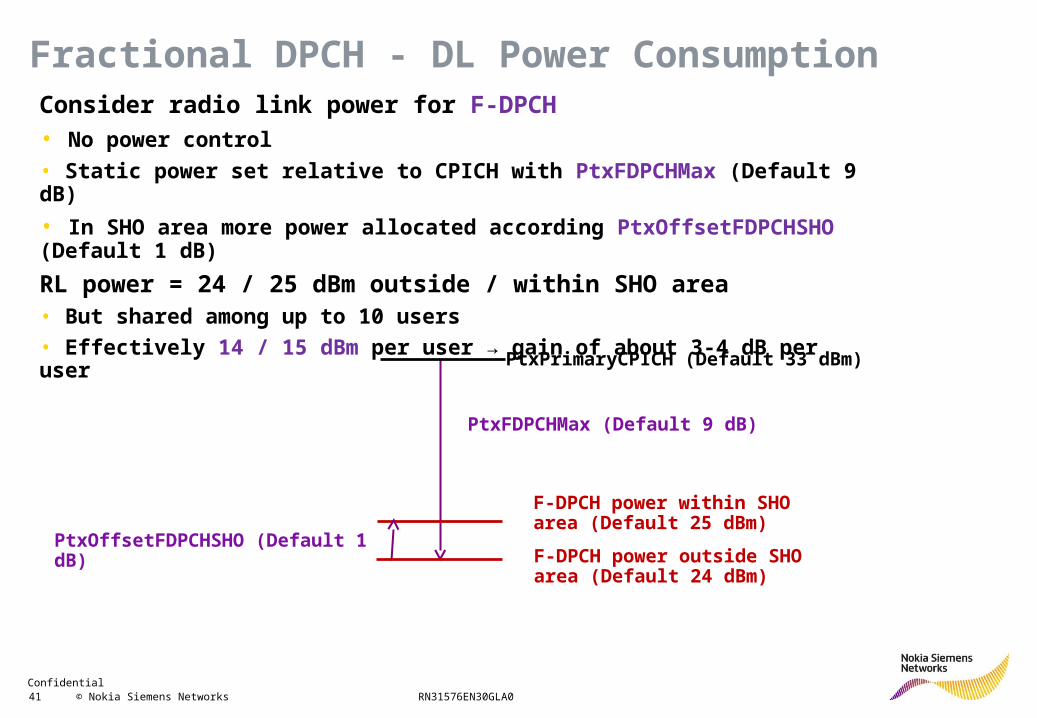
Fractional DPCH - DL Power ConsumptionConsider radio link power for F-DPCH• No power control
• Static power set relative to CPICH with PtxFDPCHMax (Default 9 dB)
• In SHO area more power allocated according PtxOffsetFDPCHSHO (Default 1 dB)
RL power = 24 / 25 dBm outside / within SHO area• But shared among up to 10 users
• Effectively 14 / 15 dBm per user → gain of about 3-4 dB per user
PtxFDPCHMax (Default 9 dB)
PtxPrimaryCPICH (Default 33 dBm)
F-DPCH power outside SHO area (Default 24 dBm)
PtxOffsetFDPCHSHO (Default 1 dB)
F-DPCH power within SHO area (Default 25 dBm)
Confidential 42 © Nokia Siemens Networks RN31576EN30GLA0
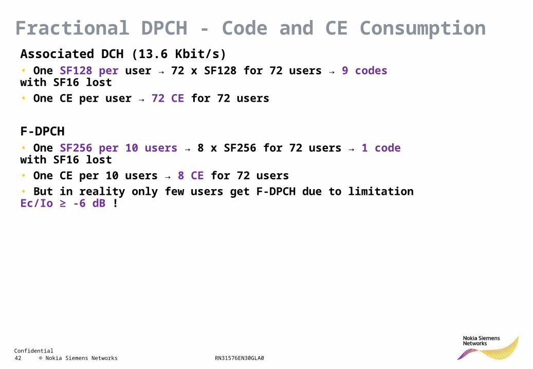
Fractional DPCH - Code and CE ConsumptionAssociated DCH (13.6 Kbit/s)• One SF128 per user → 72 x SF128 for 72 users → 9 codes with SF16 lost
• One CE per user → 72 CE for 72 users
F-DPCH• One SF256 per 10 users → 8 x SF256 for 72 users → 1 code with SF16 lost
• One CE per 10 users → 8 CE for 72 users
• But in reality only few users get F-DPCH due to limitation Ec/Io ≥ -6 dB !
Confidential 43 © Nokia Siemens Networks RN31576EN30GLA0
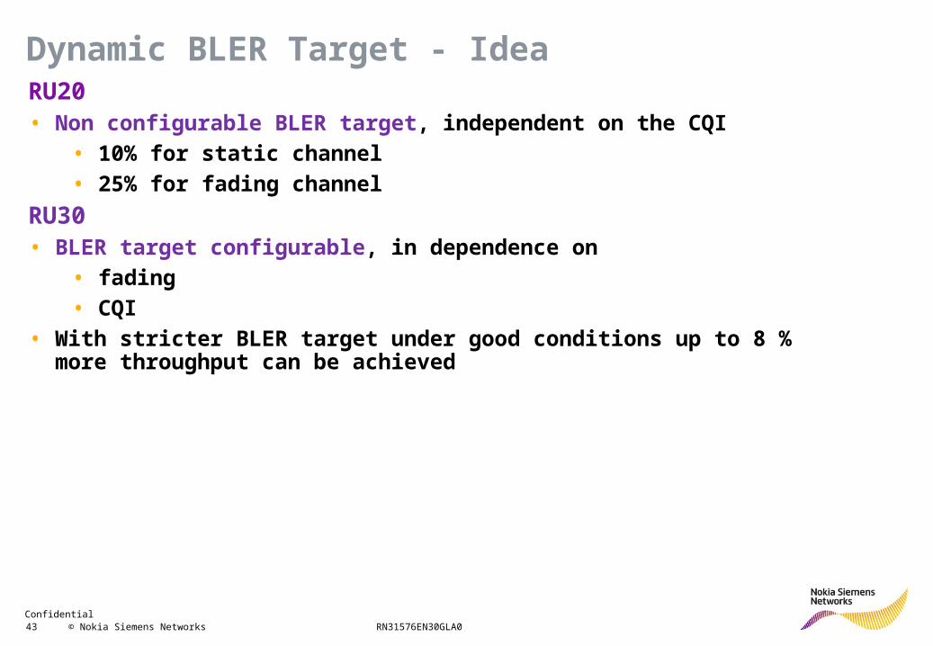
RU20• Non configurable BLER target, independent on the CQI
• 10% for static channel
• 25% for fading channel
RU30• BLER target configurable, in dependence on
• fading
• CQI
• With stricter BLER target under good conditions up to 8 % more throughput can be achieved
Dynamic BLER Target - Idea
Confidential 44 © Nokia Siemens Networks RN31576EN30GLA0
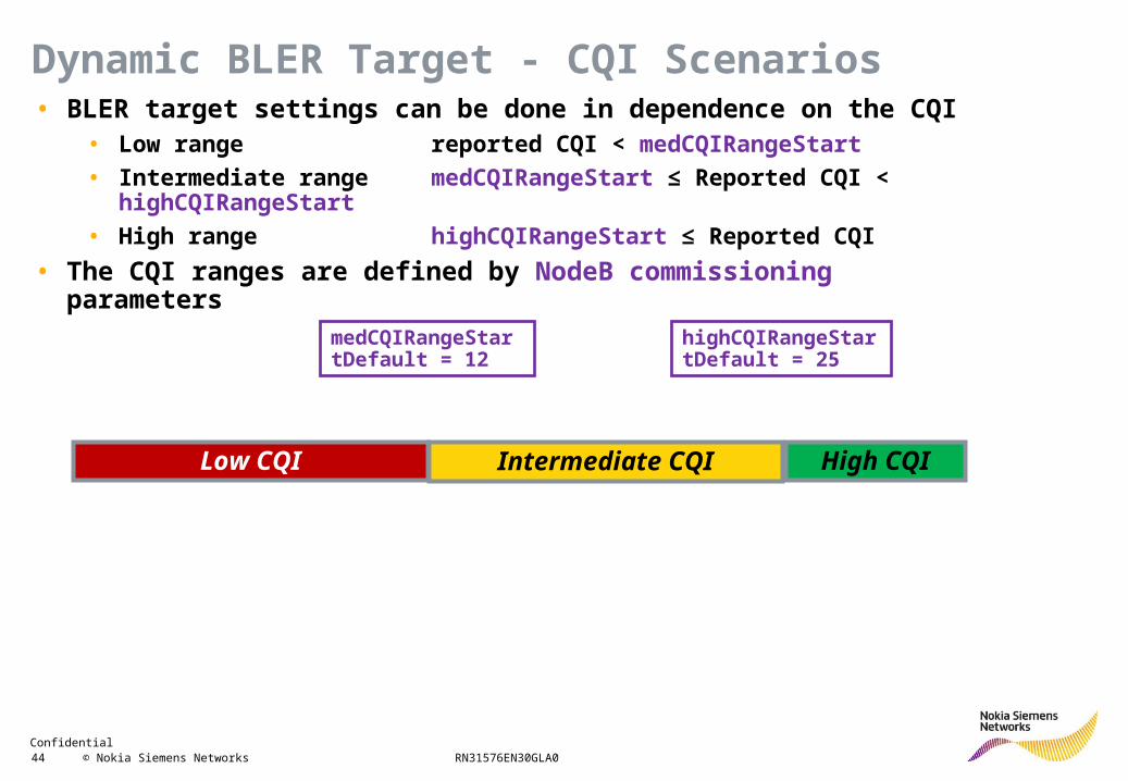
• BLER target settings can be done in dependence on the CQI• Low range reported CQI < medCQIRangeStart
• Intermediate rangemedCQIRangeStart ≤ Reported CQI < highCQIRangeStart
• High range highCQIRangeStart ≤ Reported CQI
• The CQI ranges are defined by NodeB commissioning parameters
medCQIRangeStartDefault = 12
highCQIRangeStartDefault = 25
Low CQI Intermediate CQI High CQI
Dynamic BLER Target - CQI Scenarios
Confidential 45 © Nokia Siemens Networks RN31576EN30GLA0
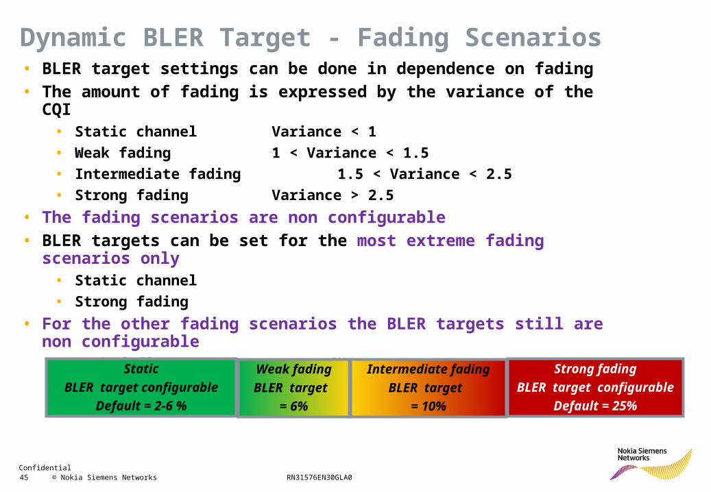
• BLER target settings can be done in dependence on fading
• The amount of fading is expressed by the variance of the CQI• Static channel Variance < 1
• Weak fading 1 < Variance < 1.5
• Intermediate fading 1.5 < Variance < 2.5
• Strong fading Variance > 2.5
• The fading scenarios are non configurable
• BLER targets can be set for the most extreme fading scenarios only• Static channel
• Strong fading
• For the other fading scenarios the BLER targets still are non configurable• Weak fading BLER target = 6%
• Intermediate fading BLER target = 10%
Static
BLER target configurable
Default = 2-6 %
Weak fading
BLER target
= 6%
Intermediate fading
BLER target
= 10%
Strong fading
BLER target configurable
Default = 25%
Dynamic BLER Target - Fading Scenarios
Confidential 46 © Nokia Siemens Networks RN31576EN30GLA0
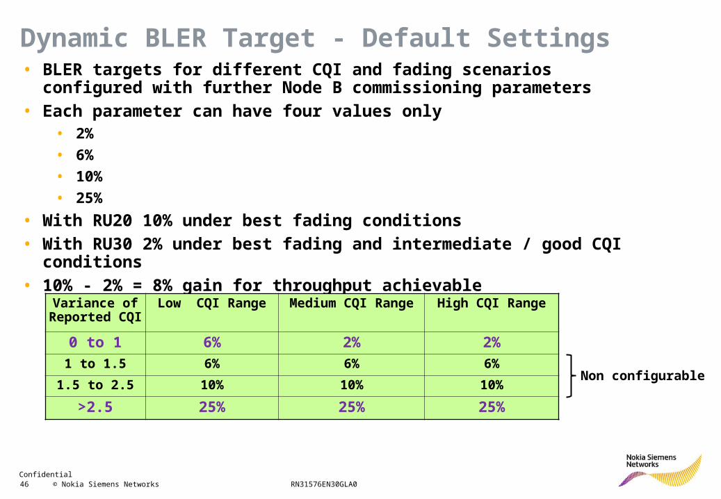
• BLER targets for different CQI and fading scenarios configured with further Node B commissioning parameters
• Each parameter can have four values only• 2%
• 6%
• 10%
• 25%
• With RU20 10% under best fading conditions
• With RU30 2% under best fading and intermediate / good CQI conditions
• 10% - 2% = 8% gain for throughput achievable
Variance of Reported CQI
Low CQI Range Medium CQI Range High CQI Range
0 to 1 6% 2% 2%
1 to 1.5 6% 6% 6%
1.5 to 2.5 10% 10% 10%
>2.5 25% 25% 25%
Dynamic BLER Target - Default Settings
Non configurable
Confidential 47 © Nokia Siemens Networks RN31576EN30GLA0
72 users
72 users72 users
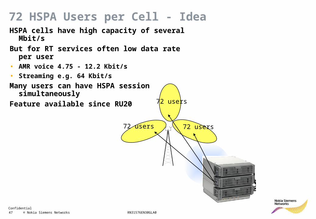
72 HSPA Users per Cell - IdeaHSPA cells have high capacity of several Mbit/s
But for RT services often low data rate per user• AMR voice 4.75 - 12.2 Kbit/s
• Streaming e.g. 64 Kbit/s
Many users can have HSPA session simultaneously
Feature available since RU20

Confidential 48 © Nokia Siemens Networks RN31576EN30GLA0
36 users
12 users24 users
72 HSPA Users per Cell - LimitationsRole of scheduler• 72 HSPA users per cell requires
• Either RU20 dedicated scheduler (full baseband)
• Or RU30 scheduler
• Otherwise 72 HSPA users per shared scheduler only
Logical and physical connection• 72 HSPA users referred to logical connection (MAC-d flow)
• Number of users served with packets simultaneously restricted by MaxNbrOfHSSCCHCodes (≤ 4)
Shared scheduler with 72 users
Confidential 49 © Nokia Siemens Networks RN31576EN30GLA0
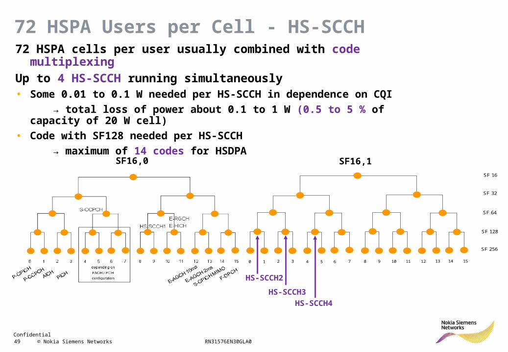
72 HSPA Users per Cell - HS-SCCH72 HSPA cells per user usually combined with code multiplexing
Up to 4 HS-SCCH running simultaneously• Some 0.01 to 0.1 W needed per HS-SCCH in dependence on CQI
→ total loss of power about 0.1 to 1 W (0.5 to 5 % of capacity of 20 W cell)
• Code with SF128 needed per HS-SCCH
→ maximum of 14 codes for HSDPA
SF 16
SF 32
SF 64
SF 128
SF 256
0 1 2 3 4 5 6 7 8 9 10 11 12 13 14 15
HS-SCCH2
HS-SCCH3
HS-SCCH4
SF16,0 SF16,1
Confidential 50 © Nokia Siemens Networks RN31576EN30GLA0
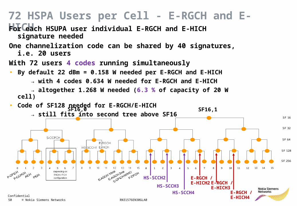
72 HSPA Users per Cell - E-RGCH and E-HICHFor each HSUPA user individual E-RGCH and E-HICH signature needed
One channelization code can be shared by 40 signatures, i.e. 20 users
With 72 users 4 codes running simultaneously• By default 22 dBm = 0.158 W needed per E-RGCH and E-HICH
→ with 4 codes 0.634 W needed for E-RGCH and E-HICH
→ altogether 1.268 W needed (6.3 % of capacity of 20 W cell)
• Code of SF128 needed for E-RGCH/E-HICH
→ still fits into second tree above SF16
SF 16
SF 32
SF 64
SF 128
SF 256
0 1 2 3 4 5 6 7 8 9 10 11 12 13 14 15
HS-SCCH2
HS-SCCH3
HS-SCCH4
SF16,0 SF16,1
E-RGCH / E-HICH2 E-RGCH /
E-HICH3E-RGCH / E-HICH4
Confidential 51 © Nokia Siemens Networks RN31576EN30GLA0
R99 Features
HSDPA
HSUPA
2ms TTI
5.8 Mbit/s
HSDPA+
HSUPA+
Capacity Enhancement
Confidential 52 © Nokia Siemens Networks RN31576EN30GLA0
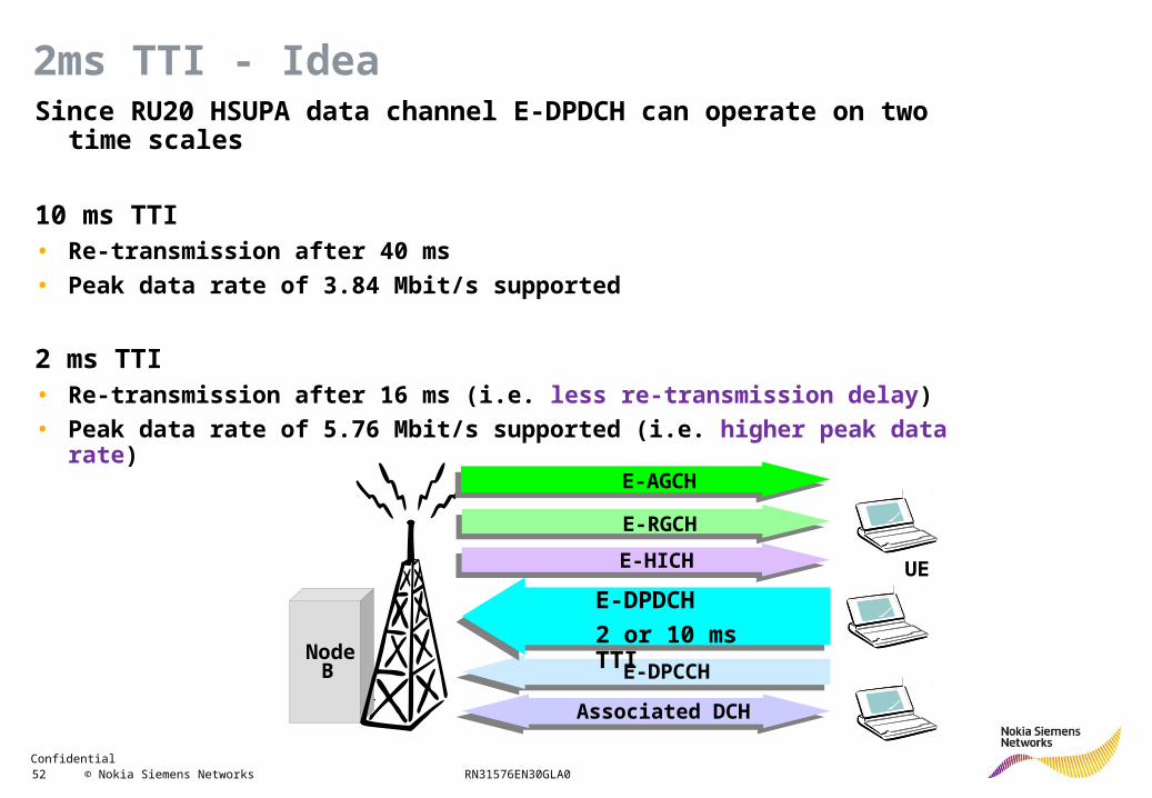
2ms TTI - IdeaSince RU20 HSUPA data channel E-DPDCH can operate on two time scales
10 ms TTI• Re-transmission after 40 ms
• Peak data rate of 3.84 Mbit/s supported
2 ms TTI• Re-transmission after 16 ms (i.e. less re-transmission delay)
• Peak data rate of 5.76 Mbit/s supported (i.e. higher peak data rate)
NodeB
associatedDCHAssociated DCH
E-DPCCHE-DPCCH
E-DPDCHE-DPDCH
2 or 10 ms TTI
E-HICHE-HICH
E-RGCHE-RGCH
E-AGCH
UE
Confidential 53 © Nokia Siemens Networks RN31576EN30GLA0
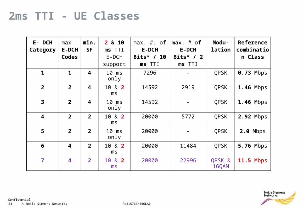
2ms TTI - UE Classes
E- DCHCategory
max. E-DCHCodes
min. SF
2 & 10 ms TTI E-DCH
support
max. #. of E-DCH Bits* /
10 ms TTI
max. # of E-DCH Bits* /
2 ms TTI
Modu- lation
Referencecombination
Class
1 1 4 10 ms only 7296 - QPSK 0.73 Mbps
2 2 4 10 & 2 ms 14592 2919 QPSK 1.46 Mbps
3 2 4 10 ms only 14592 - QPSK 1.46 Mbps
4 2 2 10 & 2 ms 20000 5772 QPSK 2.92 Mbps
5 2 2 10 ms only 20000 - QPSK 2.0 Mbps
6 4 2 10 & 2 ms 20000 11484 QPSK 5.76 Mbps
7 4 2 10 & 2 ms 20000 22996 QPSK & 16QAM
11.5 Mbps
Confidential 54 © Nokia Siemens Networks RN31576EN30GLA0
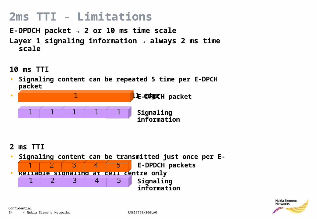
E-DPDCH packet → 2 or 10 ms time scale
Layer 1 signaling information → always 2 ms time scale
10 ms TTI• Signaling content can be repeated 5 time per E-DPCH packet
• Reliable signaling even at cell edge
2 ms TTI• Signaling content can be transmitted just once per E-DPCH packet
• Reliable signaling at cell centre only
2ms TTI - Limitations
1
1 1 1 1 1
E-DPDCH packet
Signaling information
1 2 3 4 5
E-DPDCH packets
Signaling information
Confidential 55 © Nokia Siemens Networks RN31576EN30GLA0
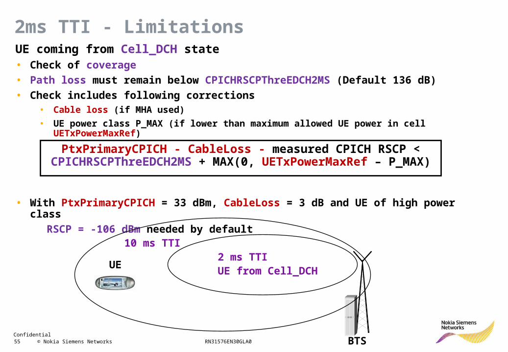
UE coming from Cell_DCH state• Check of coverage
• Path loss must remain below CPICHRSCPThreEDCH2MS (Default 136 dB)
• Check includes following corrections• Cable loss (if MHA used)
• UE power class P_MAX (if lower than maximum allowed UE power in cell UETxPowerMaxRef)
• With PtxPrimaryCPICH = 33 dBm, CableLoss = 3 dB and UE of high power class
RSCP = -106 dBm needed by default
2ms TTI - Limitations
PtxPrimaryCPICH - CableLoss - measured CPICH RSCP < CPICHRSCPThreEDCH2MS + MAX(0, UETxPowerMaxRef – P_MAX)
BTS
UE2 ms TTIUE from Cell_DCH
10 ms TTI
Confidential 56 © Nokia Siemens Networks RN31576EN30GLA0
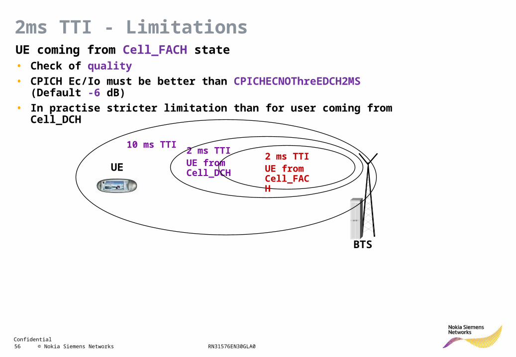
UE coming from Cell_FACH state• Check of quality
• CPICH Ec/Io must be better than CPICHECNOThreEDCH2MS (Default -6 dB)
• In practise stricter limitation than for user coming from Cell_DCH
2ms TTI - Limitations
BTS
UE
2 ms TTIUE from Cell_DCH
10 ms TTI2 ms TTIUE from Cell_FACH
Confidential 57 © Nokia Siemens Networks RN31576EN30GLA0
2ms TTI - ExampleSimulation performed by Qualcomm based on 3GPP TR 25.896 specifications
Network assumptions• Network with hexagonal cells of inter-site distance of 1000 m
• Users uniformly distributed
Receiver assumptions• Rake receiver and 2Rx diversity at Node B
• Rake receiver or equalizer at UE, without or with 2Rx diversity
Voice transmission assumptions• 12.2 Kbit/s
• VoIP with robust header compression
• DTX cycle of 8 TTIs for TTI = 2 ms and of 2 TTIs for TTI = 10 ms
Confidential 58 © Nokia Siemens Networks RN31576EN30GLA0
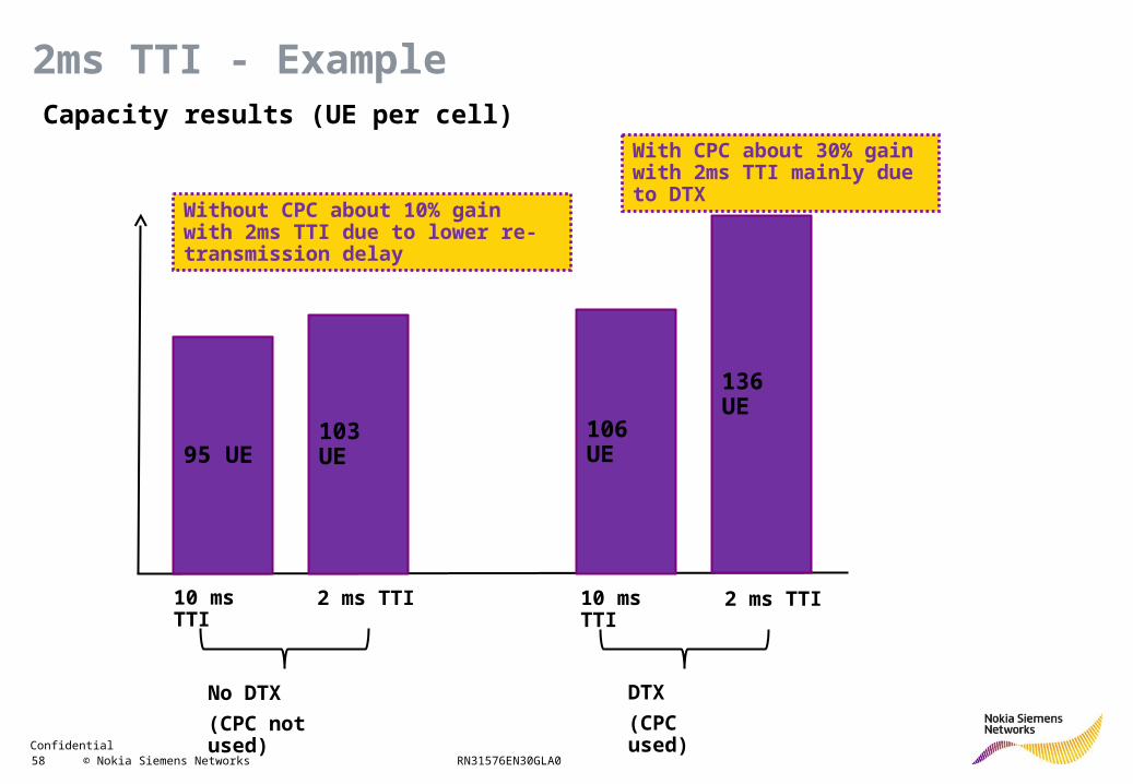
2ms TTI - ExampleCapacity results (UE per cell)
95 UE 103 UE
10 ms TTI 2 ms TTI
106 UE
136 UE
10 ms TTI 2 ms TTI
No DTX
(CPC not used)
DTX
(CPC used)
Without CPC about 10% gain with 2ms TTI due to lower re-transmission delay
With CPC about 30% gain with 2ms TTI mainly due to DTX
Confidential 59 © Nokia Siemens Networks RN31576EN30GLA0
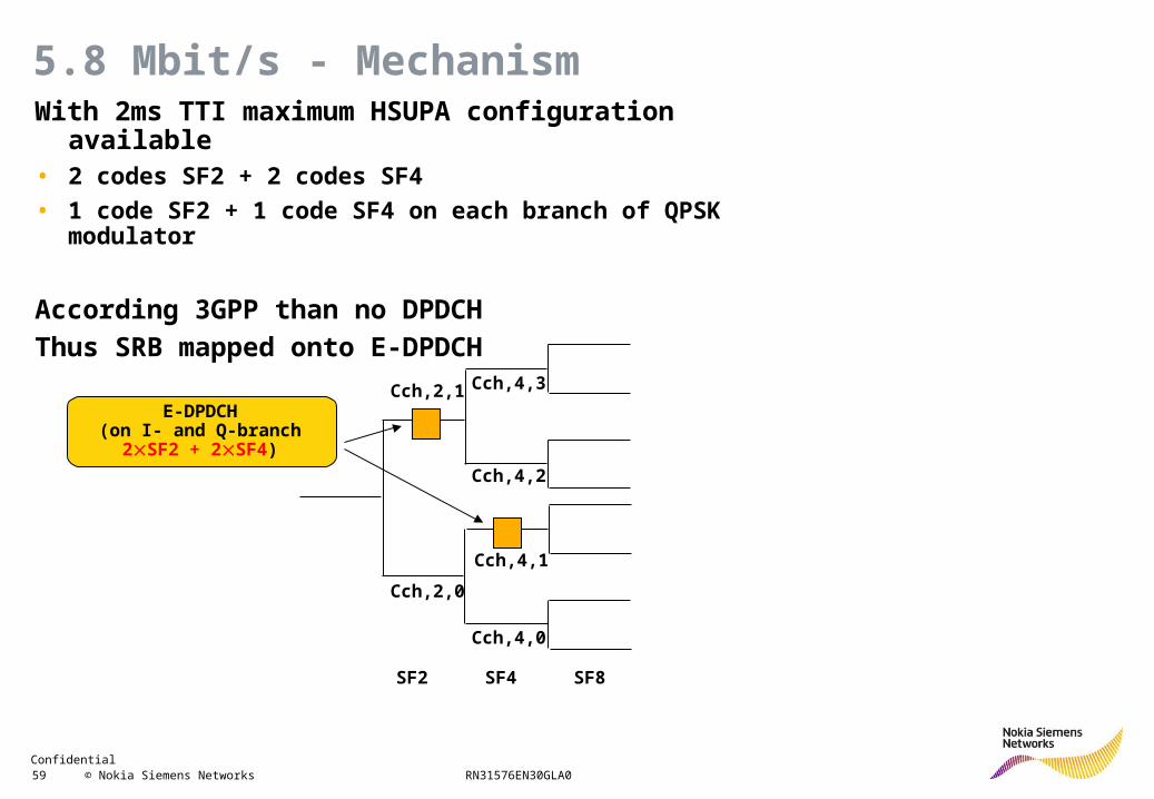
5.8 Mbit/s - MechanismWith 2ms TTI maximum HSUPA configuration available• 2 codes SF2 + 2 codes SF4
• 1 code SF2 + 1 code SF4 on each branch of QPSK modulator
According 3GPP than no DPDCH
Thus SRB mapped onto E-DPDCH
SF2 SF4 SF8
Cch,2,0
Cch,2,1
Cch,4,0
Cch,4,1
Cch,4,2
Cch,4,3
E-DPDCH(on I- and Q-branch
2SF2 + 2SF4)
Confidential 60 © Nokia Siemens Networks RN31576EN30GLA0
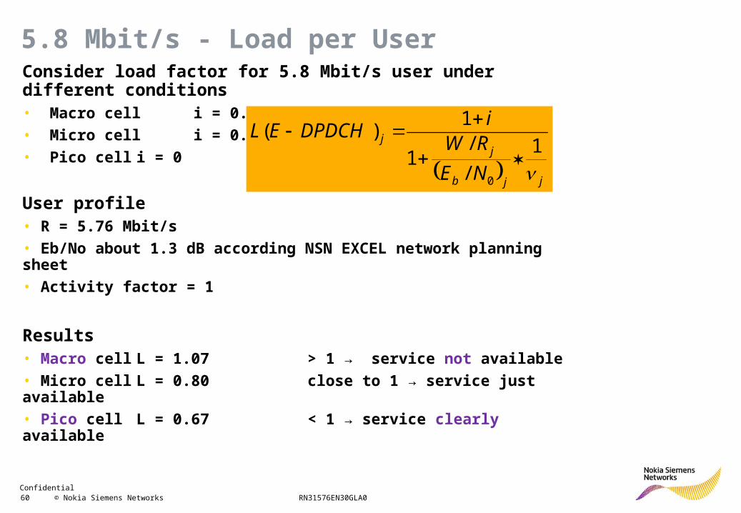
5.8 Mbit/s - Load per UserConsider load factor for 5.8 Mbit/s user under different conditions• Macro cell i = 0.6
• Micro cell i = 0.2
• Pico cell i = 0
User profile• R = 5.76 Mbit/s
• Eb/No about 1.3 dB according NSN EXCEL network planning sheet
• Activity factor = 1
Results• Macro cell L = 1.07 > 1 → service not available
• Micro cell L = 0.80 close to 1 → service just available
• Pico cell L = 0.67 < 1 → service clearly available
jjb
jj
NE
RWi
DPDCHEL
1
/
/1
1)(
0
Confidential 61 © Nokia Siemens Networks RN31576EN30GLA0
R99 Features
HSDPA
HSUPA
HSDPA+
Flexible RLC
64QAM and MIMO
Dual cell HSDPA
HS Cell_FACH
CS voice over HSPA
Continuous packet connectivity
HSUPA+
Capacity Enhancement
Confidential 62 © Nokia Siemens Networks RN31576EN30GLA0
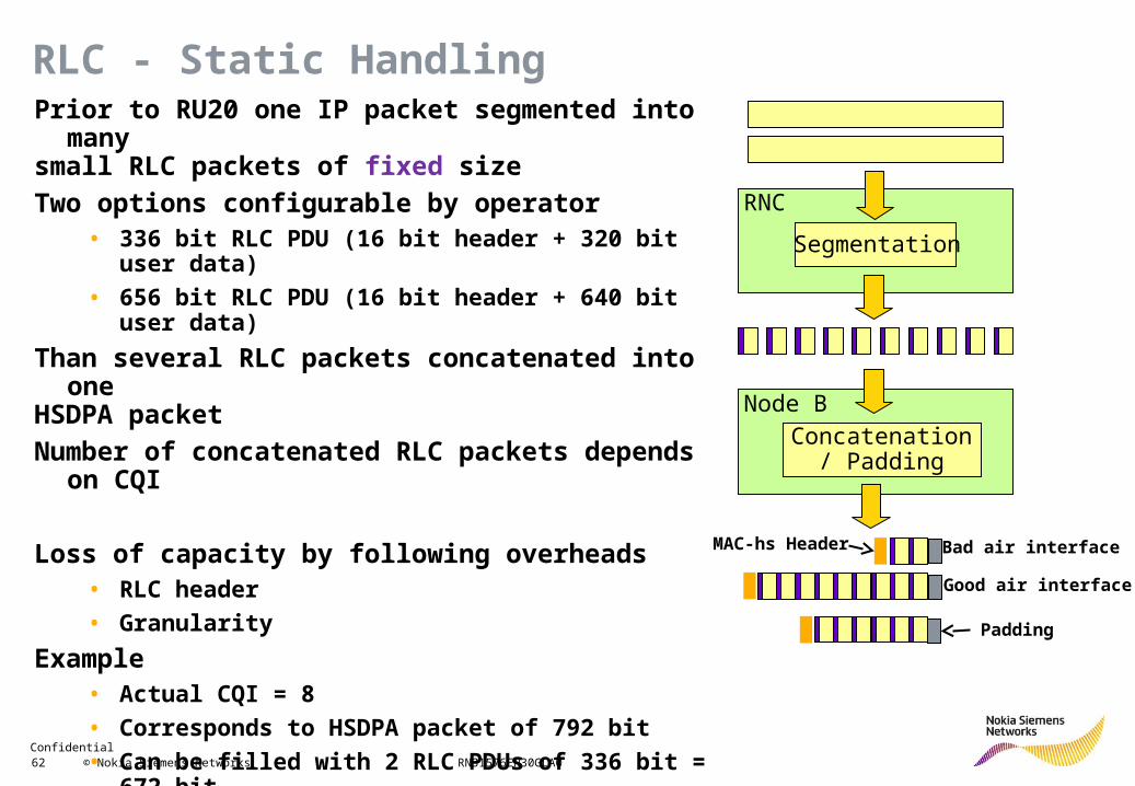
Prior to RU20 one IP packet segmented into many small RLC packets of fixed size
Two options configurable by operator• 336 bit RLC PDU (16 bit header + 320 bit user data)
• 656 bit RLC PDU (16 bit header + 640 bit user data)
Than several RLC packets concatenated into one HSDPA packet
Number of concatenated RLC packets depends on CQI
Loss of capacity by following overheads• RLC header
• Granularity
Example• Actual CQI = 8
• Corresponds to HSDPA packet of 792 bit
• Can be filled with 2 RLC PDUs of 336 bit = 672 bit
• Remaining 792 - 672 = 120 bit remain unused
RLC - Static Handling
Segmentation
RNC
Node B
Concatenation / Padding
MAC-hs Header
Good air interface
Bad air interface
Padding
Confidential 63 © Nokia Siemens Networks RN31576EN30GLA0
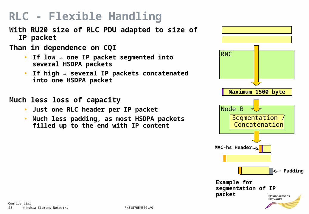
With RU20 size of RLC PDU adapted to size of IP packet
Than in dependence on CQI• If low → one IP packet segmented into several HSDPA
packets
• If high → several IP packets concatenated into one HSDPA packet
Much less loss of capacity• Just one RLC header per IP packet
• Much less padding, as most HSDPA packets filled up to the end with IP content
RLC - Flexible Handling
RNC
Segmentation / Concatenation
Node B
Maximum 1500 byte
Padding
MAC-hs Header
Example for segmentation of IP packet
Confidential 64 © Nokia Siemens Networks RN31576EN30GLA0
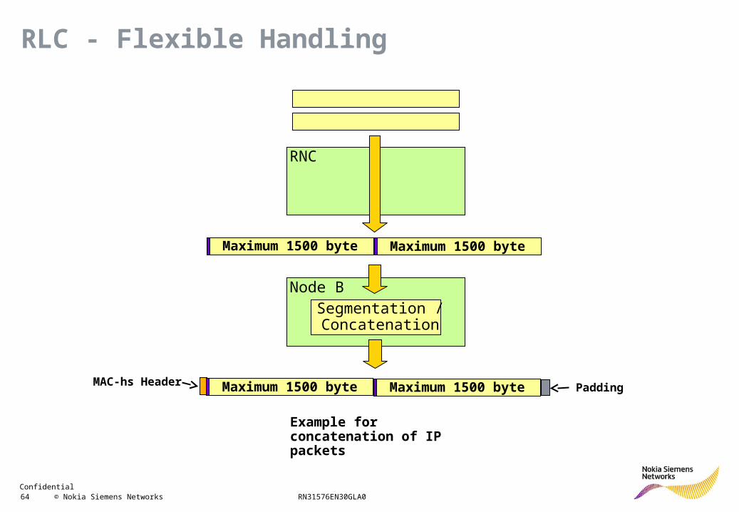
RLC - Flexible Handling
Example for concatenation of IP packets
RNC
Segmentation / Concatenation
Node B
Maximum 1500 byte
PaddingMAC-hs Header
Maximum 1500 byte
Maximum 1500 byteMaximum 1500 byte
Confidential 65 © Nokia Siemens Networks RN31576EN30GLA0
0%
5%
10%
15%
20%
25%
30%
35%
40%
45%
50%
0 100 200 300 400 500 600 700 800 900 1000 1100 1200 1300 1400 1500
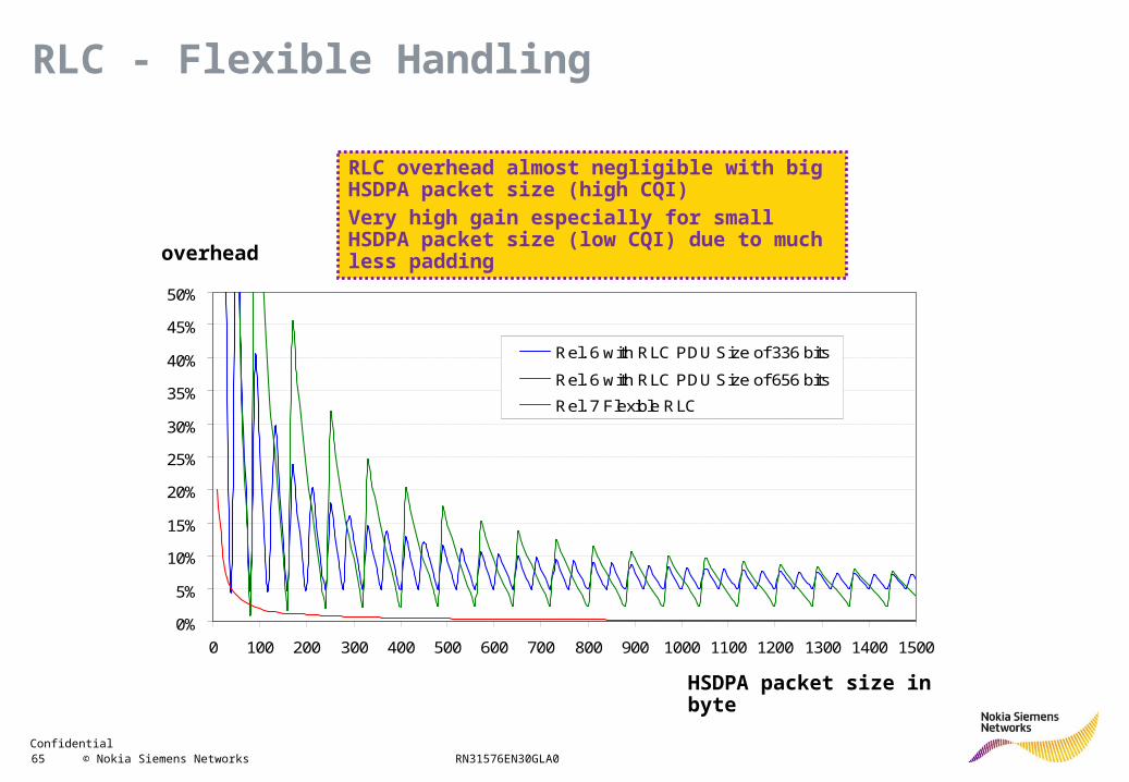
Rel. 6 with RLC PDU Size of 336 bits
Rel. 6 with RLC PDU Size of 656 bits
Rel. 7 Flexible RLC
overhead
HSDPA packet size in byte
RLC - Flexible Handling
RLC overhead almost negligible with big HSDPA packet size (high CQI)Very high gain especially for small HSDPA packet size (low CQI) due to much less padding
Confidential 66 © Nokia Siemens Networks RN31576EN30GLA0
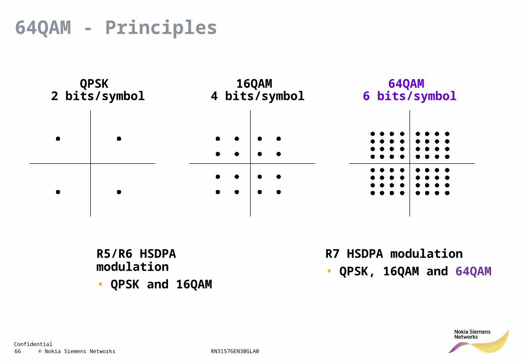
QPSK 2 bits/symbol
16QAM 4 bits/symbol
64QAM 6 bits/symbol
R5/R6 HSDPA modulation
• QPSK and 16QAM
R7 HSDPA modulation
• QPSK, 16QAM and 64QAM
64QAM - Principles
Confidential 67 © Nokia Siemens Networks RN31576EN30GLA0
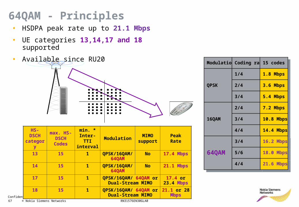
ModulationModulation
QPSKQPSK
Coding rateCoding rate
1/41/4
2/42/4
3/43/4
15 codes15 codes
1.8 Mbps1.8 Mbps
3.6 Mbps3.6 Mbps
5.4 Mbps5.4 Mbps
16QAM16QAM
2/42/4
3/43/4
4/44/4
7.2 Mbps7.2 Mbps
10.8 Mbps10.8 Mbps
14.4 Mbps14.4 Mbps
64QAM64QAM
3/43/4
5/65/6
4/44/4
16.2 Mbps16.2 Mbps
18.0 Mbps18.0 Mbps
21.6 Mbps21.6 Mbps
HS- DSCH
category
max. HS-DSCH Codes
min. * Inter-TTI interval
ModulationMIMO
supportPeakRate
13 15 1 QPSK/16QAM/ 64QAM
No 17.4 Mbps
14 15 1 QPSK/16QAM/ 64QAM
No 21.1 Mbps
17 15 1 QPSK/16QAM/ 64QAM or Dual-Stream MIMO
17.4 or 23.4 Mbps
18 15 1 QPSK/16QAM/ 64QAM or Dual-Stream MIMO
21.1 or 28 Mbps
• HSDPA peak rate up to 21.1 Mbps
• UE categories 13,14,17 and 18 supported
• Available since RU20
64QAM - Principles
Confidential 68 © Nokia Siemens Networks RN31576EN30GLA0
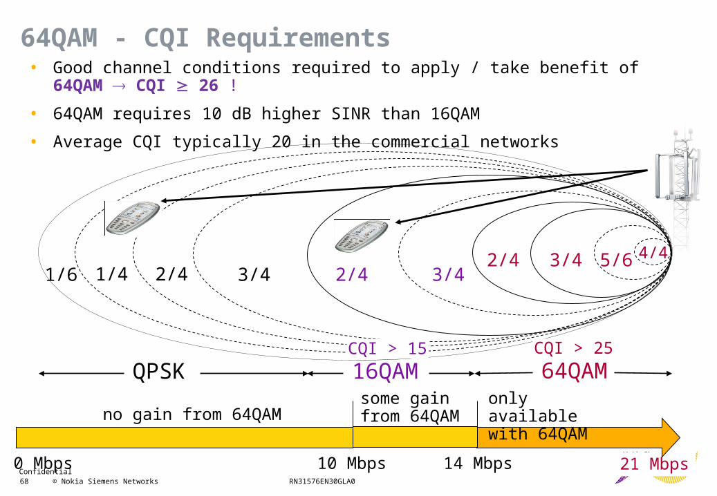
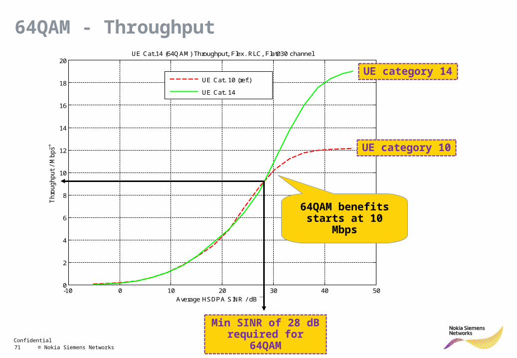
• Good channel conditions required to apply / take benefit of 64QAM CQI 26 !
• 64QAM requires 10 dB higher SINR than 16QAM
• Average CQI typically 20 in the commercial networks
21 Mbps0 Mbps 10 Mbps 14 Mbps
no gain from 64QAMsome gain from 64QAM
only available with 64QAM
64QAMQPSK 16QAM
1/4 2/42/4
1/6 2/4 3/4 3/43/4 5/6 4/4
CQI > 15 CQI > 25
64QAM - CQI Requirements
Confidential 69 © Nokia Siemens Networks RN31576EN30GLA0
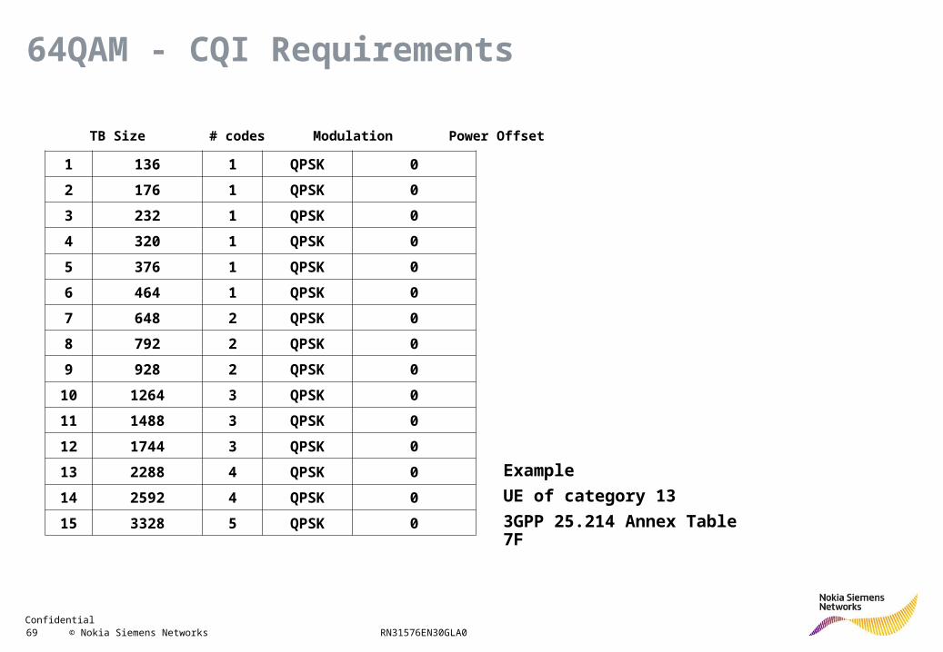
1 136 1 QPSK 0
2 176 1 QPSK 0
3 232 1 QPSK 0
4 320 1 QPSK 0
5 376 1 QPSK 0
6 464 1 QPSK 0
7 648 2 QPSK 0
8 792 2 QPSK 0
9 928 2 QPSK 0
10 1264 3 QPSK 0
11 1488 3 QPSK 0
12 1744 3 QPSK 0
13 2288 4 QPSK 0
14 2592 4 QPSK 0
15 3328 5 QPSK 0
CQI TB Size # codes Modulation Power Offset
64QAM - CQI Requirements
Example
UE of category 13
3GPP 25.214 Annex Table 7F
Confidential 70 © Nokia Siemens Networks RN31576EN30GLA0
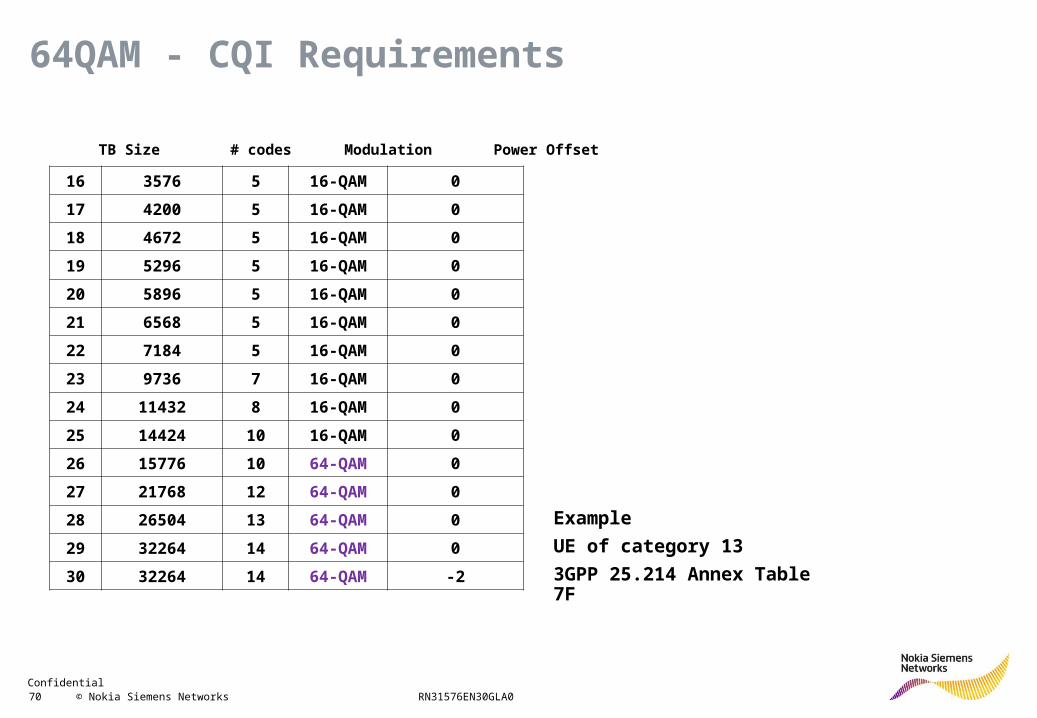
16 3576 5 16-QAM 0
17 4200 5 16-QAM 0
18 4672 5 16-QAM 0
19 5296 5 16-QAM 0
20 5896 5 16-QAM 0
21 6568 5 16-QAM 0
22 7184 5 16-QAM 0
23 9736 7 16-QAM 0
24 11432 8 16-QAM 0
25 14424 10 16-QAM 0
26 15776 10 64-QAM 0
27 21768 12 64-QAM 0
28 26504 13 64-QAM 0
29 32264 14 64-QAM 0
30 32264 14 64-QAM -2
64QAM - CQI Requirements
CQI TB Size # codes Modulation Power Offset
Example
UE of category 13
3GPP 25.214 Annex Table 7F
Confidential 71 © Nokia Siemens Networks RN31576EN30GLA0
-10 0 10 20 30 40 500
2
4
6
8
10
12
14
16
18
20UE Cat.14 (64QAM) Throughput, Flex. RLC, Flat030 channel
Average HSDPA SINR / dB
Thro
ughput
/ M
bps
UE Cat. 10 (ref.)
UE Cat. 14
64QAM benefits starts at 10 Mbps
UE category 10
UE category 14
Min SINR of 28 dB required for 64QAM
64QAM - Throughput
Confidential 72 © Nokia Siemens Networks RN31576EN30GLA0
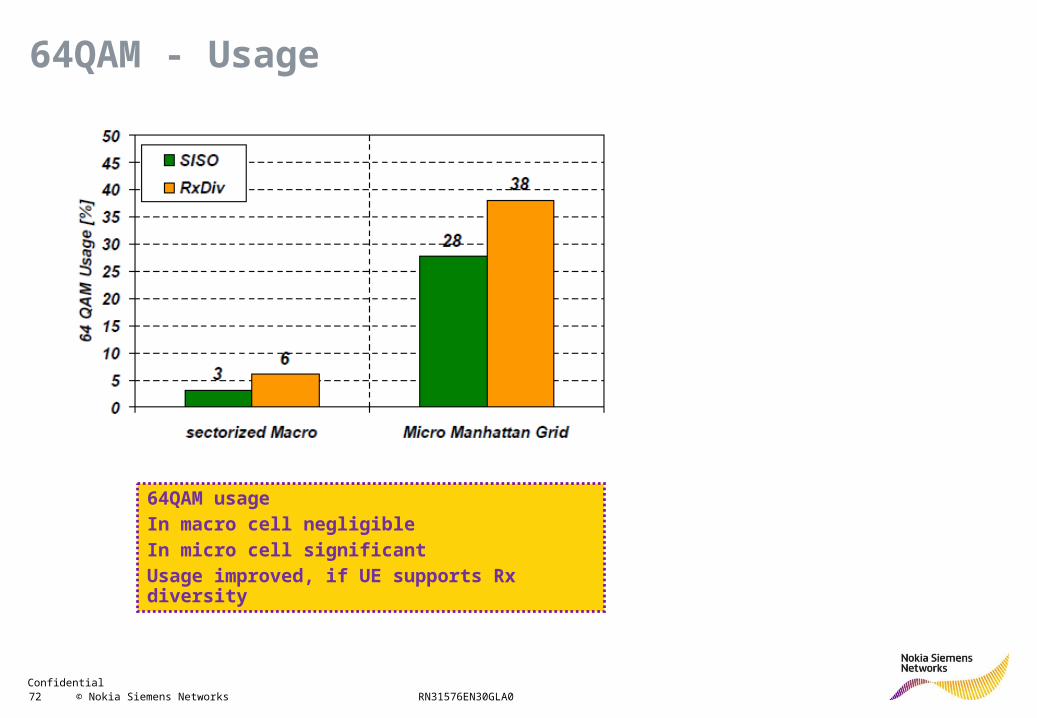
64QAM - Usage
64QAM usageIn macro cell negligibleIn micro cell significantUsage improved, if UE supports Rx diversity
Confidential 73 © Nokia Siemens Networks RN31576EN30GLA0
Tm
T2
T1
Rn
R2
R1
•••
•••
Input
Input 1
Input 2
Input m M x NMIMO system
OutputMIMOProcessor
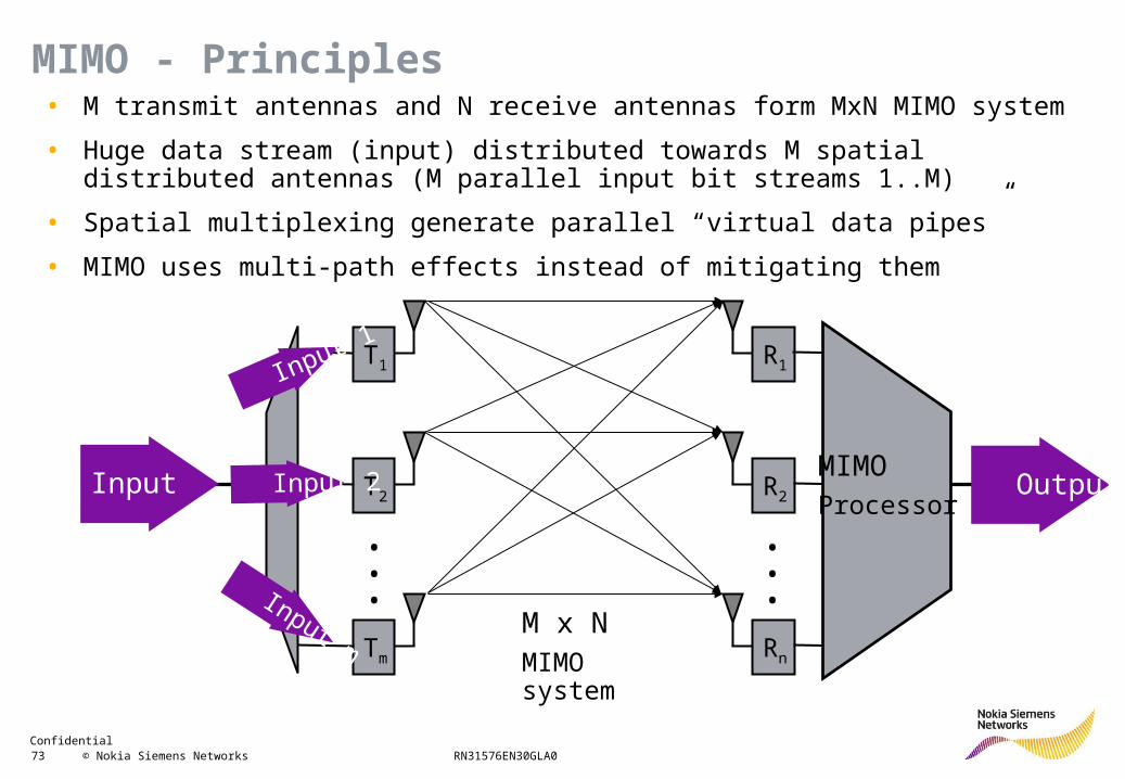
• M transmit antennas and N receive antennas form MxN MIMO system
• Huge data stream (input) distributed towards M spatial distributed antennas (M parallel input bit streams 1..M)
• Spatial multiplexing generate parallel “virtual data pipes”
• MIMO uses multi-path effects instead of mitigating them
MIMO - Principles
Confidential 74 © Nokia Siemens Networks RN31576EN30GLA0
HS- DSCH
category
max. HS-DSCH Codes
min. * Inter-TTI interval
ModulationMIMO
supportPeakRate
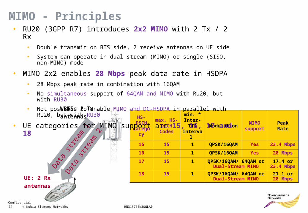
15 15 1 QPSK/16QAM Yes 23.4 Mbps
16 15 1 QPSK/16QAM Yes 28 Mbps
17 15 1 QPSK/16QAM/ 64QAM or Dual-Stream MIMO
17.4 or 23.4 Mbps
18 15 1 QPSK/16QAM/ 64QAM or Dual-Stream MIMO
21.1 or 28 MbpsD
ata
stre
am 1
UE: 2 Rx
antennas
WBTS: 2 Tx
antennas
Dat
a st
ream
2
• RU20 (3GPP R7) introduces 2x2 MIMO with 2 Tx / 2 Rx
• Double transmit on BTS side, 2 receive antennas on UE side
• System can operate in dual stream (MIMO) or single (SISO, non-MIMO) mode
• MIMO 2x2 enables 28 Mbps peak data rate in HSDPA
• 28 Mbps peak rate in combination with 16QAM
• No simultaneous support of 64QAM and MIMO with RU20, but with RU30
• Not possible to enable MIMO and DC-HSDPA in parallel with RU20, but with RU30
• UE categories for MIMO support are 15, 16, 17 and 18
MIMO - Principles
Confidential 75 © Nokia Siemens Networks RN31576EN30GLA0
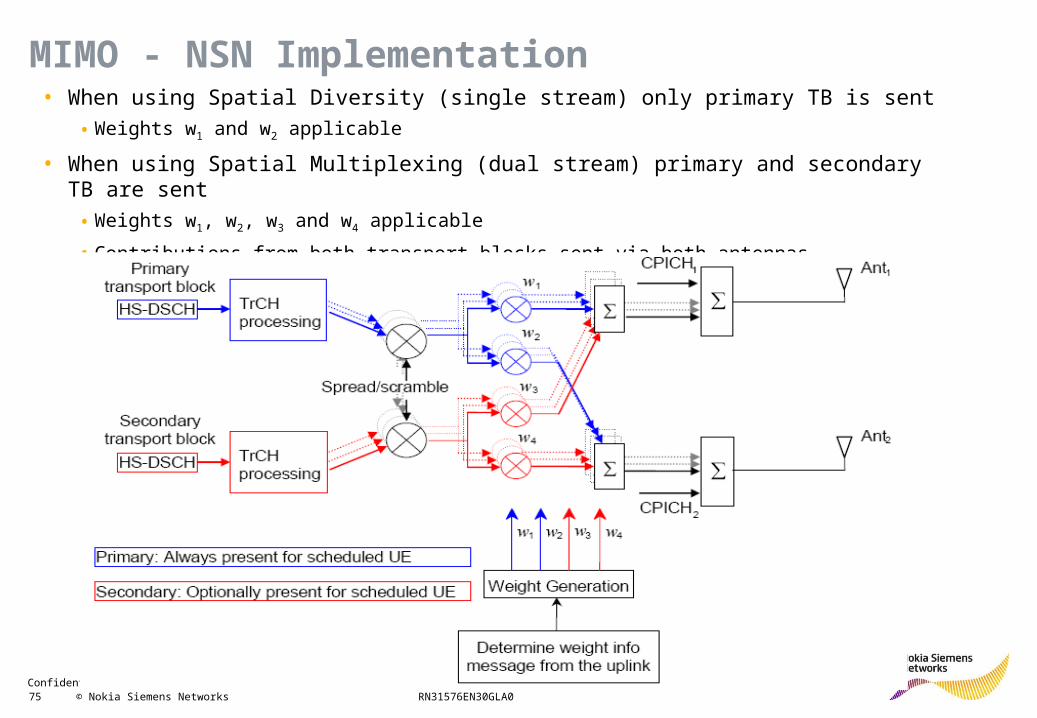
• When using Spatial Diversity (single stream) only primary TB is sent
• Weights w1 and w2 applicable
• When using Spatial Multiplexing (dual stream) primary and secondary TB are sent
• Weights w1, w2, w3 and w4 applicable
• Contributions from both transport blocks sent via both antennas
MIMO - NSN Implementation
Confidential 76 © Nokia Siemens Networks RN31576EN30GLA0
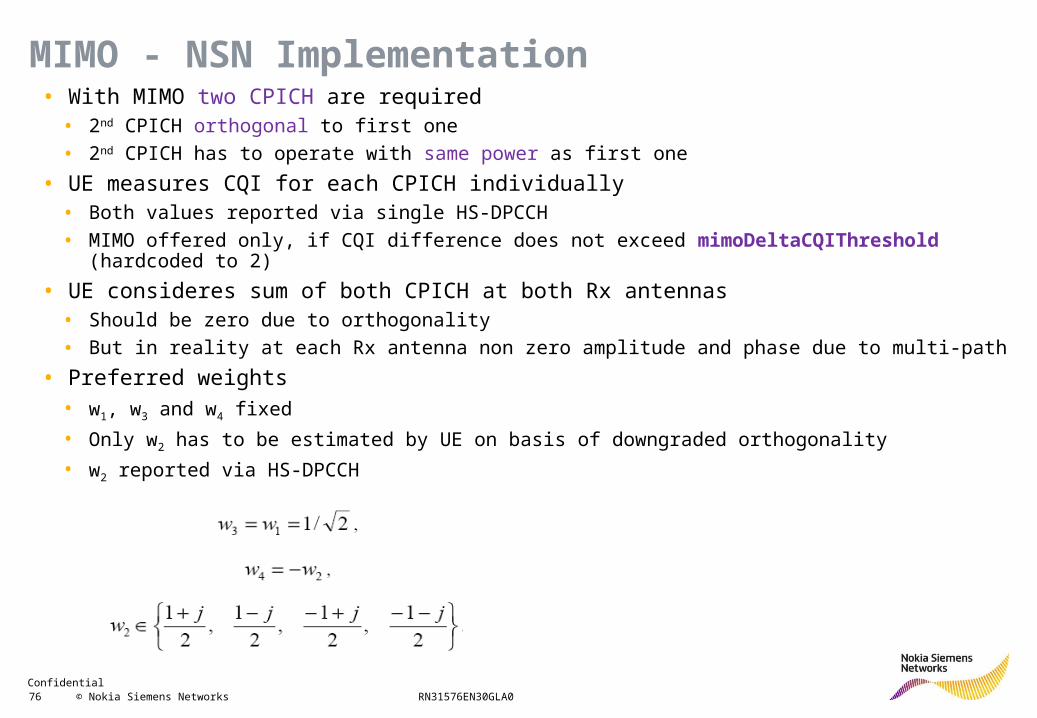
• With MIMO two CPICH are required• 2nd CPICH orthogonal to first one
• 2nd CPICH has to operate with same power as first one
• UE measures CQI for each CPICH individually• Both values reported via single HS-DPCCH
• MIMO offered only, if CQI difference does not exceed mimoDeltaCQIThreshold (hardcoded to 2)
• UE consideres sum of both CPICH at both Rx antennas• Should be zero due to orthogonality
• But in reality at each Rx antenna non zero amplitude and phase due to multi-path
• Preferred weights• w1, w3 and w4 fixed
• Only w2 has to be estimated by UE on basis of downgraded orthogonality
• w2 reported via HS-DPCCH
MIMO - NSN Implementation
Confidential 77 © Nokia Siemens Networks RN31576EN30GLA0
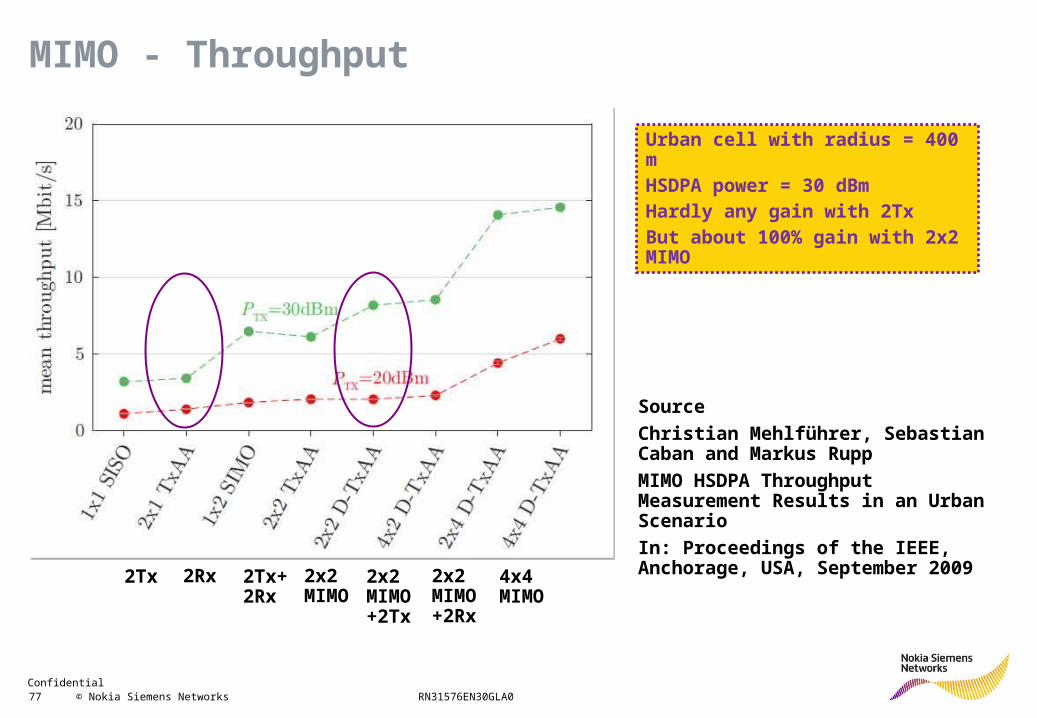
MIMO - Throughput
Source
Christian Mehlführer, Sebastian Caban and Markus Rupp
MIMO HSDPA Throughput Measurement Results in an Urban Scenario
In: Proceedings of the IEEE, Anchorage, USA, September 2009
2Tx 2Rx 2Tx+ 2Rx
2x2 MIMO
2x2 MIMO+2Tx
2x2 MIMO +2Rx
4x4 MIMO
Urban cell with radius = 400 mHSDPA power = 30 dBmHardly any gain with 2TxBut about 100% gain with 2x2 MIMO
Confidential 78 © Nokia Siemens Networks RN31576EN30GLA0
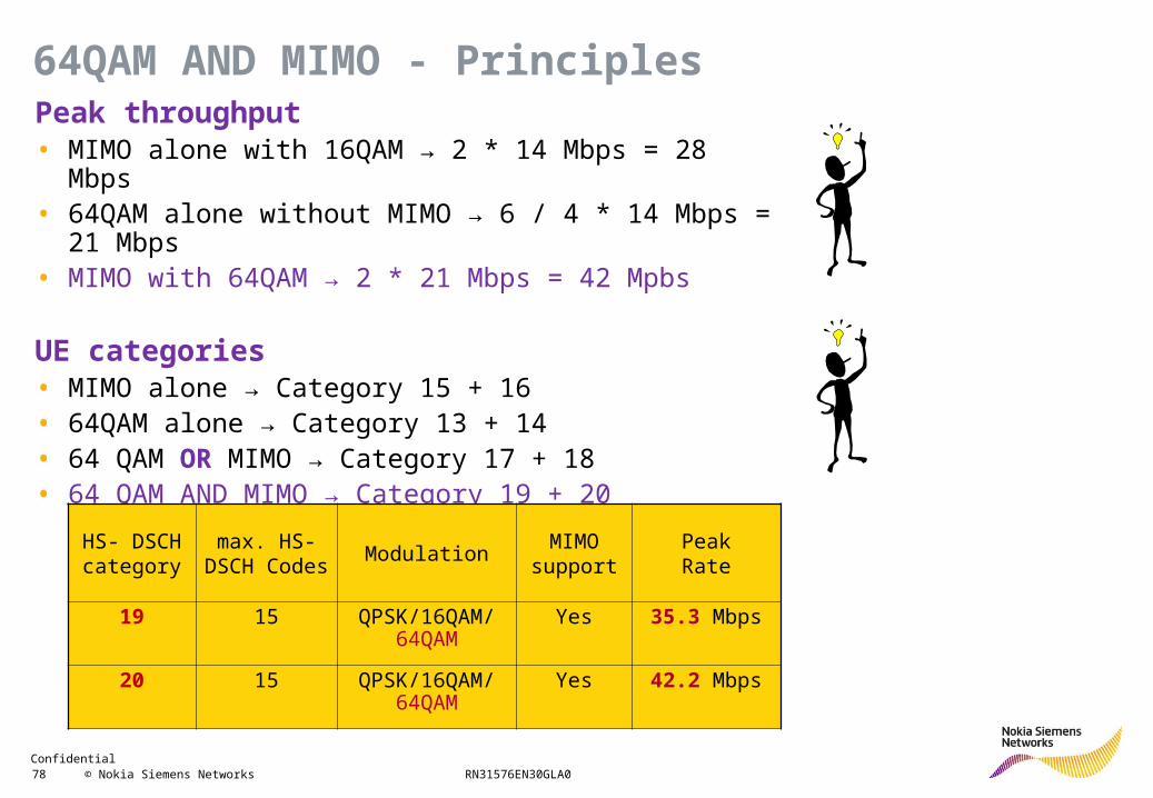
Peak throughput• MIMO alone with 16QAM → 2 * 14 Mbps = 28 Mbps• 64QAM alone without MIMO → 6 / 4 * 14 Mbps = 21 Mbps• MIMO with 64QAM → 2 * 21 Mbps = 42 Mpbs
UE categories• MIMO alone → Category 15 + 16• 64QAM alone → Category 13 + 14• 64 QAM OR MIMO → Category 17 + 18• 64 QAM AND MIMO → Category 19 + 20
HS- DSCHcategory
max. HS-DSCH Codes
ModulationMIMO
supportPeakRate
19 15 QPSK/16QAM/ 64QAM
Yes 35.3 Mbps
20 15 QPSK/16QAM/ 64QAM
Yes 42.2 Mbps
64QAM AND MIMO - Principles
Confidential 79 © Nokia Siemens Networks RN31576EN30GLA0
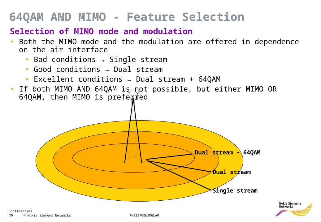
Selection of MIMO mode and modulation• Both the MIMO mode and the modulation are offered in dependence on the air
interface• Bad conditions → Single stream• Good conditions → Dual stream• Excellent conditions → Dual stream + 64QAM
• If both MIMO AND 64QAM is not possible, but either MIMO OR 64QAM, then MIMO is preferred
Dual stream + 64QAM
Dual stream
Single stream
64QAM AND MIMO - Feature Selection
Confidential 80 © Nokia Siemens Networks RN31576EN30GLA0
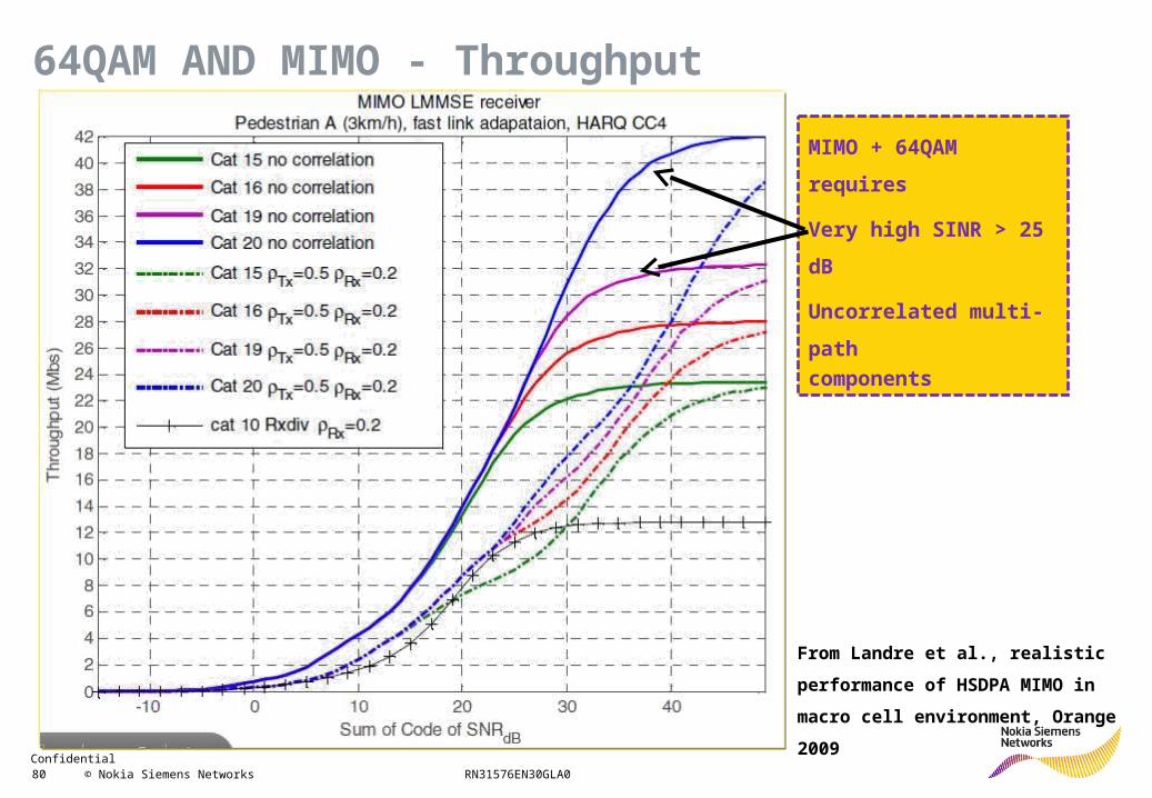
MIMO + 64QAM requires
Very high SINR > 25 dB
Uncorrelated multi-path
components
From Landre et al., realistic performance
of HSDPA MIMO in macro cell
environment, Orange 2009
64QAM AND MIMO - Throughput
Confidential 81 © Nokia Siemens Networks RN31576EN30GLA0
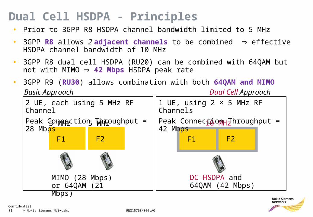
5 MHz 5 MHz
F1 F2
MIMO (28 Mbps) or 64QAM (21 Mbps)
10 MHz
DC-HSDPA and 64QAM (42 Mbps)
2 UE, each using 5 MHz RF Channel
Peak Connection Throughput = 28 Mbps
1 UE, using 2 × 5 MHz RF Channels
Peak Connection Throughput = 42 Mbps
F1 F2
Dual Cell ApproachBasic Approach
• Prior to 3GPP R8 HSDPA channel bandwidth limited to 5 MHz
• 3GPP R8 allows 2 adjacent channels to be combined effective HSDPA channel bandwidth of 10 MHz
• 3GPP R8 dual cell HSDPA (RU20) can be combined with 64QAM but not with MIMO 42 Mbps HSDPA peak rate
• 3GPP R9 (RU30) allows combination with both 64QAM and MIMO
Dual Cell HSDPA - Principles
Confidential 82 © Nokia Siemens Networks RN31576EN30GLA0
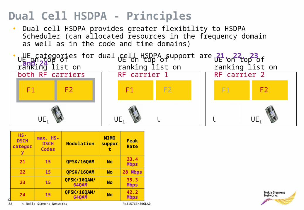
F1 F2F1 F2 F1 F2
UE on top of ranking list on both RF carriers
UE on top of ranking list on RF carrier 1
UE on top of ranking list on RF carrier 2
UEx UExUE1UE1 UE1
• Dual cell HSDPA provides greater flexibility to HSDPA Scheduler (can allocated resources in the frequency domain as well as in the code and time domains)
• UE categories for dual cell HSDPA support are 21, 22, 23 and 24
HS- DSCH
category
max. HS-DSCH Codes
ModulationMIMO
supportPeakRate
21 15 QPSK/16QAM No 23.4 Mbps
22 15 QPSK/16QAM No 28 Mbps
23 15 QPSK/16QAM/64QAM No 35.3
Mbps
24 15 QPSK/16QAM/64QAM No 42.2
Mbps
Dual Cell HSDPA - Principles
Confidential 83 © Nokia Siemens Networks RN31576EN30GLA0
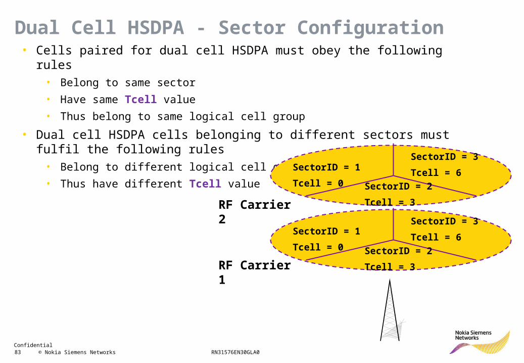
• Cells paired for dual cell HSDPA must obey the following rules• Belong to same sector
• Have same Tcell value
• Thus belong to same logical cell group
• Dual cell HSDPA cells belonging to different sectors must fulfil the following rules• Belong to different logical cell groups
• Thus have different Tcell valueSectorID = 1
Tcell = 0
RF Carrier 2
SectorID = 2
Tcell = 3
SectorID = 3
Tcell = 6
SectorID = 1
Tcell = 0 SectorID = 2
Tcell = 3
SectorID = 3
Tcell = 6
RF Carrier 1
Dual Cell HSDPA - Sector Configuration
Confidential 84 © Nokia Siemens Networks RN31576EN30GLA0
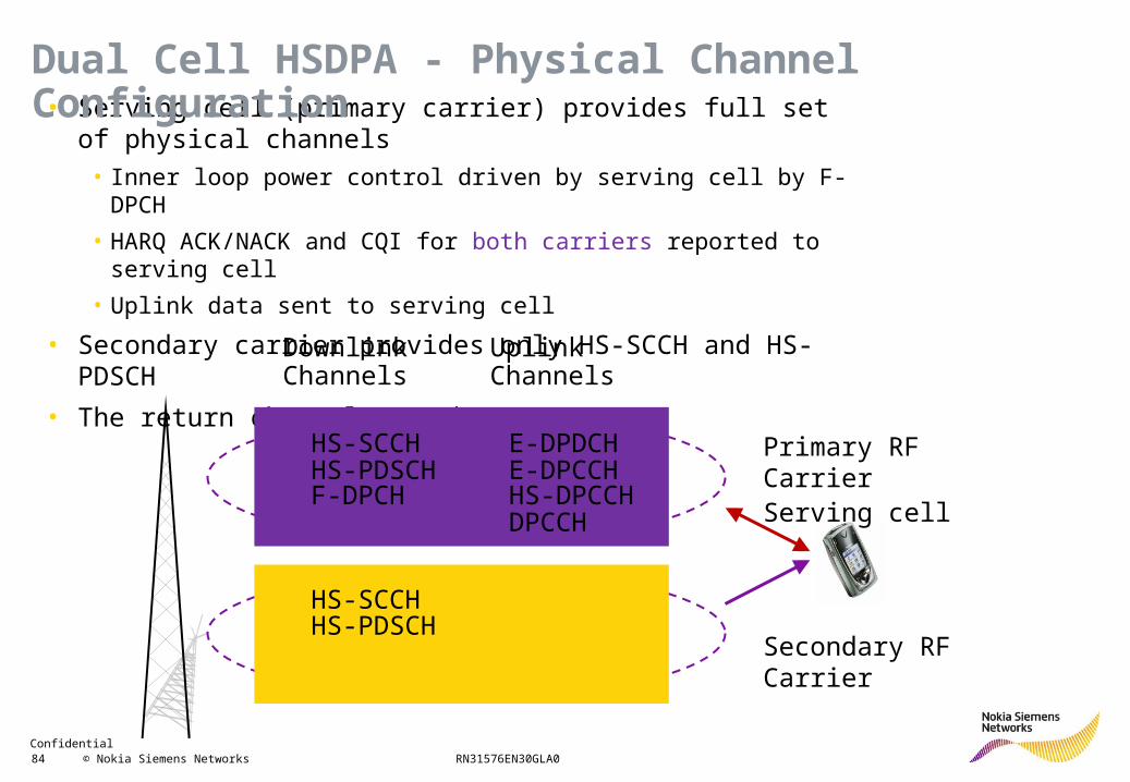
• Serving cell (primary carrier) provides full set of physical channels• Inner loop power control driven by serving cell by F-DPCH
• HARQ ACK/NACK and CQI for both carriers reported to serving cell
• Uplink data sent to serving cell
• Secondary carrier provides only HS-SCCH and HS-PDSCH
• The return channel must be HSUPA
HS-SCCH
HS-SCCHHS-PDSCH
HS-PDSCHHS-DPCCHDPCCH
F-DPCH
E-DPDCHE-DPCCH
Downlink Channels
Uplink Channels
Primary RF CarrierServing cell
Secondary RF Carrier
Dual Cell HSDPA - Physical Channel Configuration
Confidential 85 © Nokia Siemens Networks RN31576EN30GLA0
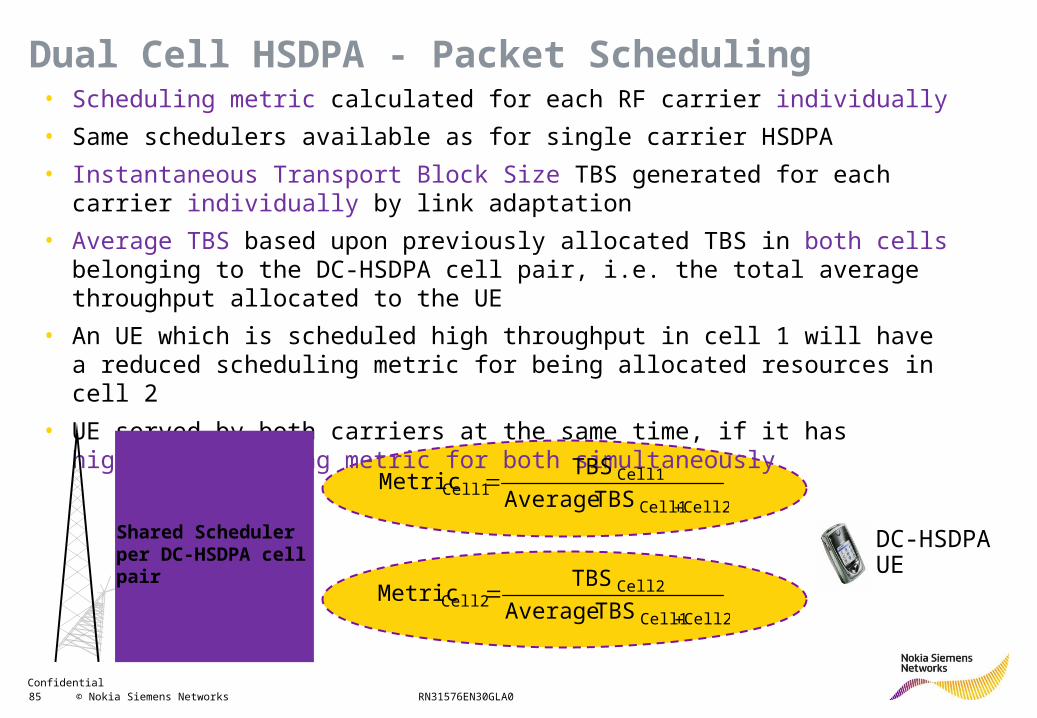
• Scheduling metric calculated for each RF carrier individually
• Same schedulers available as for single carrier HSDPA
• Instantaneous Transport Block Size TBS generated for each carrier individually by link adaptation
• Average TBS based upon previously allocated TBS in both cells belonging to the DC-HSDPA cell pair, i.e. the total average throughput allocated to the UE
• An UE which is scheduled high throughput in cell 1 will have a reduced scheduling metric for being allocated resources in cell 2
• UE served by both carriers at the same time, if it has highest scheduling metric for both simultaneously
Cell2Cell1
Cell1Cell1 TBS Average
TBS Metric
Cell2Cell1
Cell2Cell2 TBS Average
TBS Metric
Shared Scheduler per DC-HSDPA cell pair
DC-HSDPA UE
Dual Cell HSDPA - Packet Scheduling
Confidential 86 © Nokia Siemens Networks RN31576EN30GLA0
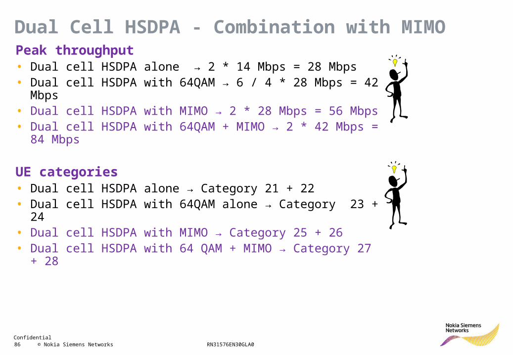
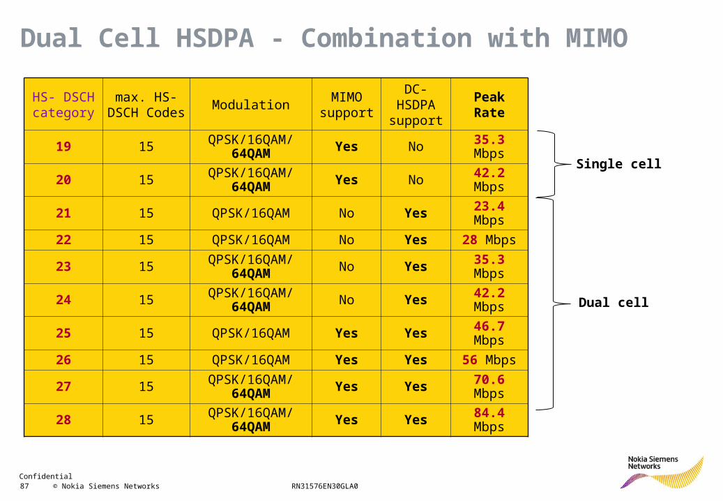
Peak throughput• Dual cell HSDPA alone → 2 * 14 Mbps = 28 Mbps• Dual cell HSDPA with 64QAM → 6 / 4 * 28 Mbps = 42 Mbps• Dual cell HSDPA with MIMO → 2 * 28 Mbps = 56 Mbps• Dual cell HSDPA with 64QAM + MIMO → 2 * 42 Mbps = 84 Mbps
UE categories• Dual cell HSDPA alone → Category 21 + 22• Dual cell HSDPA with 64QAM alone → Category 23 + 24• Dual cell HSDPA with MIMO → Category 25 + 26• Dual cell HSDPA with 64 QAM + MIMO → Category 27 + 28
Dual Cell HSDPA - Combination with MIMO
Confidential 87 © Nokia Siemens Networks RN31576EN30GLA0
HS- DSCHcategory
max. HS-DSCH Codes
ModulationMIMO
support
DC-HSDPA support
PeakRate
19 15 QPSK/16QAM/ 64QAM Yes No 35.3 Mbps
20 15 QPSK/16QAM/ 64QAM Yes No 42.2 Mbps
21 15 QPSK/16QAM No Yes 23.4 Mbps
22 15 QPSK/16QAM No Yes 28 Mbps
23 15 QPSK/16QAM/ 64QAM No Yes 35.3 Mbps
24 15 QPSK/16QAM/ 64QAM No Yes 42.2 Mbps
25 15 QPSK/16QAM Yes Yes 46.7 Mbps
26 15 QPSK/16QAM Yes Yes 56 Mbps
27 15 QPSK/16QAM/ 64QAM Yes Yes 70.6 Mbps
28 15 QPSK/16QAM/ 64QAM Yes Yes 84.4 Mbps
Single cell
Dual cell
Dual Cell HSDPA - Combination with MIMO
Confidential 88 © Nokia Siemens Networks RN31576EN30GLA0
HS-DPCCH
Other common channels like
E-AGCH, E-RGCH, F-DPCH
Other common channels like
E-AGCH, E-RGCH, F-DPCH UE
BTS
HS-SCCH
HS-SCCH
HS-DSCH
TBS3
TBS4HS-DSCH
TBS1
TBS2
Primary Cell
Secondary Cell
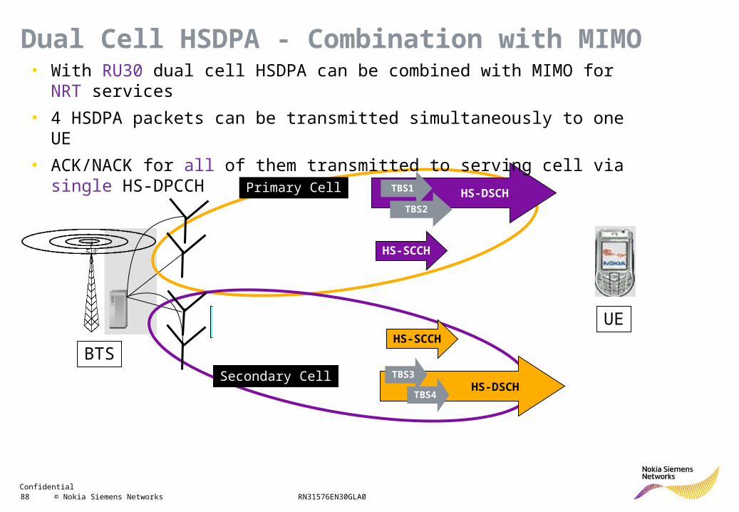
Dual Cell HSDPA - Combination with MIMO• With RU30 dual cell HSDPA can be combined with MIMO for NRT services
• 4 HSDPA packets can be transmitted simultaneously to one UE
• ACK/NACK for all of them transmitted to serving cell via single HS-DPCCH
Confidential 89 © Nokia Siemens Networks RN31576EN30GLA0
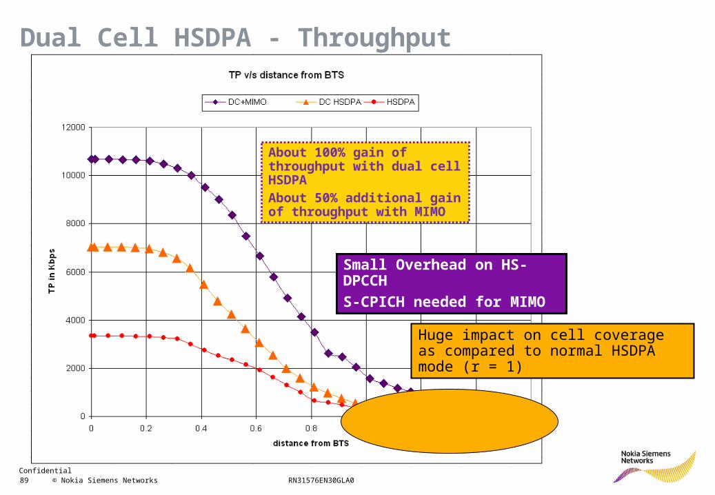
Huge impact on cell coverage as compared to normal HSDPA mode (r = 1)
Small Overhead on HS-DPCCH
S-CPICH needed for MIMO
Dual Cell HSDPA - Throughput
About 100% gain of throughput with dual cell HSDPAAbout 50% additional gain of throughput with MIMO
Confidential 90 © Nokia Siemens Networks RN31576EN30GLA0
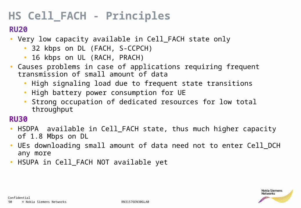
RU20• Very low capacity available in Cell_FACH state only
• 32 kbps on DL (FACH, S-CCPCH)• 16 kbps on UL (RACH, PRACH)
• Causes problems in case of applications requiring frequent transmission of small amount of data
• High signaling load due to frequent state transitions• High battery power consumption for UE• Strong occupation of dedicated resources for low total throughput
RU30• HSDPA available in Cell_FACH state, thus much higher capacity of 1.8 Mbps on DL• UEs downloading small amount of data need not to enter Cell_DCH any more• HSUPA in Cell_FACH NOT available yet
HS Cell_FACH - Principles
Confidential 91 © Nokia Siemens Networks RN31576EN30GLA0
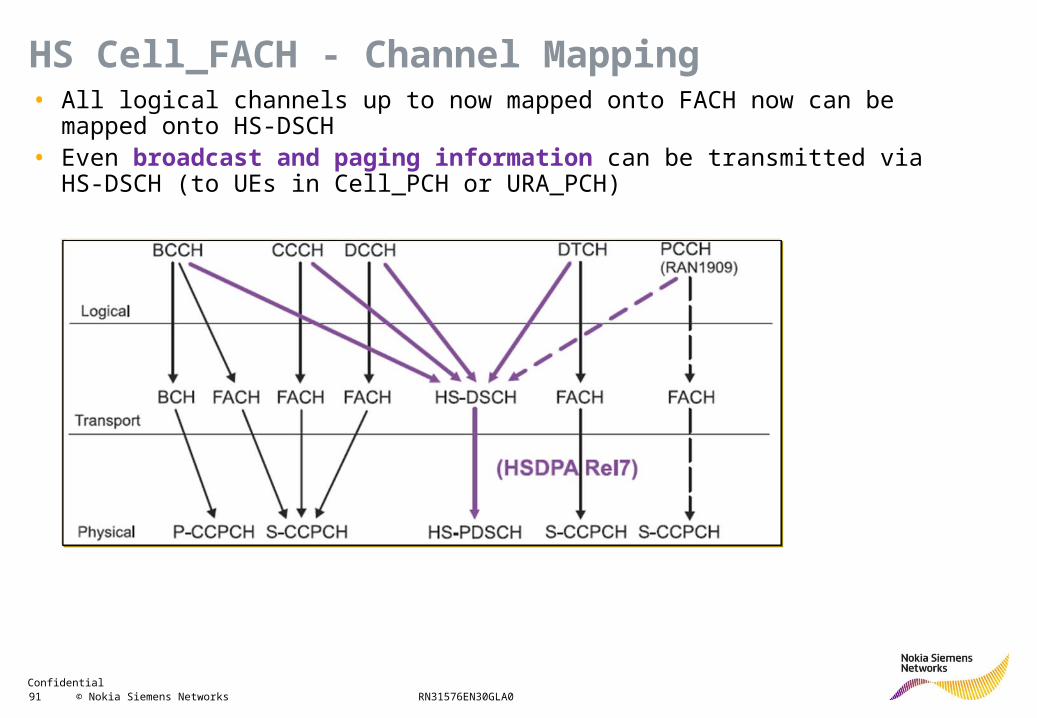
• All logical channels up to now mapped onto FACH now can be mapped onto HS-DSCH
• Even broadcast and paging information can be transmitted via HS-DSCH (to UEs in Cell_PCH or URA_PCH)
HS Cell_FACH - Channel Mapping
Confidential 92 © Nokia Siemens Networks RN31576EN30GLA0
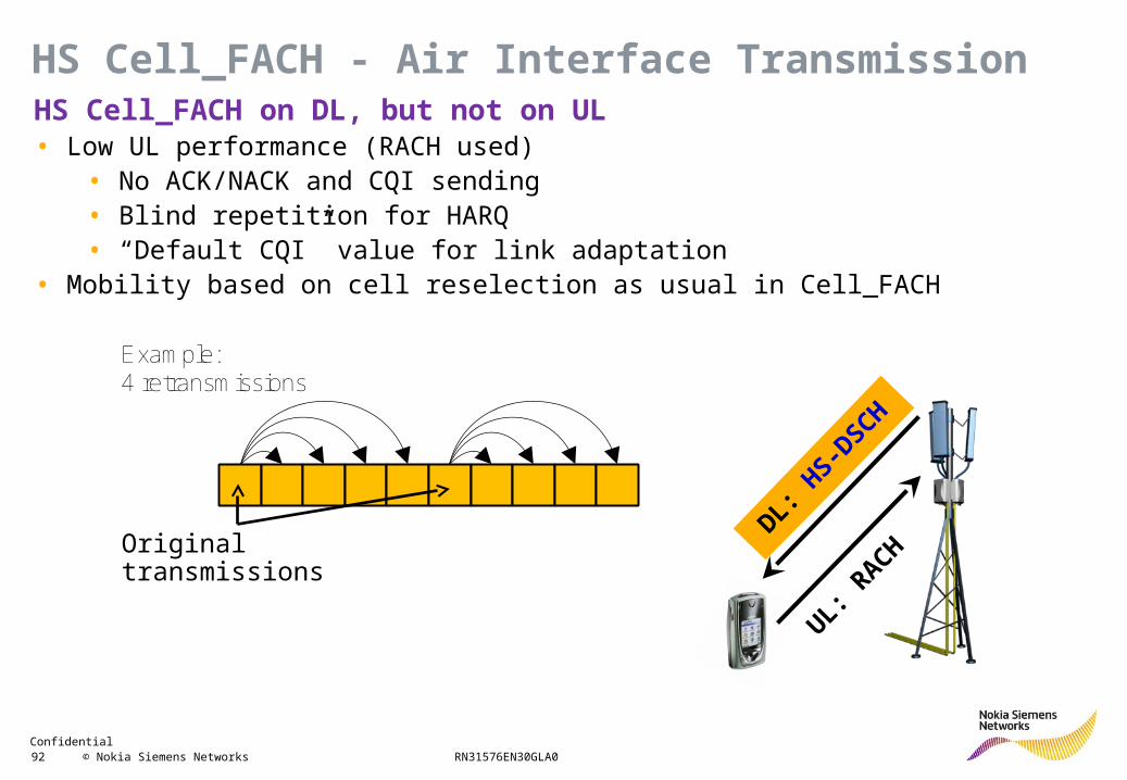
HS Cell_FACH on DL, but not on UL• Low UL performance (RACH used)
• No ACK/NACK and CQI sending• Blind repetition for HARQ • “Default CQI” value for link adaptation
• Mobility based on cell reselection as usual in Cell_FACH
DL: HS-D
SCH
UL: RACHHS-DPSCH
Example:4 retransmissions
Original transmissions
HS Cell_FACH - Air Interface Transmission
Confidential 93 © Nokia Siemens Networks RN31576EN30GLA0
• Like for R99• One can select for which RRC establishment cause HS Cell_FACH or HS Cell_DCH is
preferred• Transition Cell_FACH to Cell_DCH triggered by high activity, i.e. huge amount of data in DL
RLC buffer
• In contradiction to R99• Cell_FACH can be offered, until no resource available in this state any more• Thresholds FachLoadThresholdCCH and PtxThresholdCCH are ignored
HS Cell_FACH - Channel Type Selection
Confidential 94 © Nokia Siemens Networks RN31576EN30GLA0
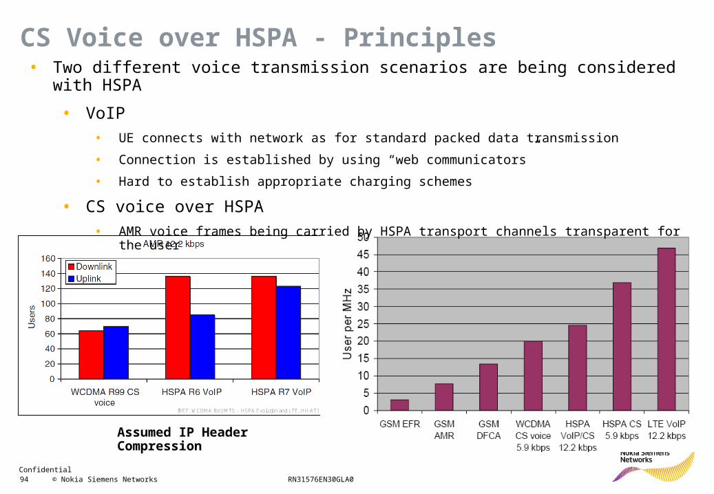
[REF. WCDMA for UMTS – HSPA Evolution and LTE, HH AT]
Assumed IP Header Compression
• Two different voice transmission scenarios are being considered with HSPA
• VoIP
• UE connects with network as for standard packed data transmission
• Connection is established by using “web communicators”
• Hard to establish appropriate charging schemes
• CS voice over HSPA
• AMR voice frames being carried by HSPA transport channels transparent for the user
CS Voice over HSPA - Principles
Confidential 95 © Nokia Siemens Networks RN31576EN30GLA0
HS-DSCH
E-DCH
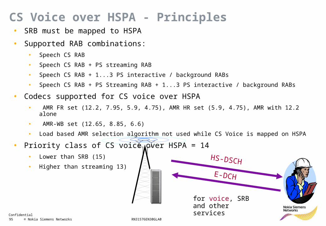
for voice, SRB and other services
• SRB must be mapped to HSPA
• Supported RAB combinations:
• Speech CS RAB
• Speech CS RAB + PS streaming RAB
• Speech CS RAB + 1...3 PS interactive / background RABs
• Speech CS RAB + PS Streaming RAB + 1...3 PS interactive / background RABs
• Codecs supported for CS voice over HSPA
• AMR FR set (12.2, 7.95, 5.9, 4.75), AMR HR set (5.9, 4.75), AMR with 12.2 alone
• AMR-WB set (12.65, 8.85, 6.6)
• Load based AMR selection algorithm not used while CS Voice is mapped on HSPA
• Priority class of CS voice over HSPA = 14
• Lower than SRB (15)
• Higher than streaming 13)
CS Voice over HSPA - Principles
Confidential 96 © Nokia Siemens Networks RN31576EN30GLA0
PtxTargetTotMin (40 dBm)
CS Voice over HSPA - DL Admission Control
Common channels
DCH voice + SRB
DCH streaming
DCH NRT
HSDPA voice + SRB
HSDPA streaming
HSDPA NRT
PtxCellMax (43 dBm)
PtxTargetTotMax (41 dBm)
PtxTarget (40 dBm)
PtxNCDCH
PtxNCHSDPA
Power
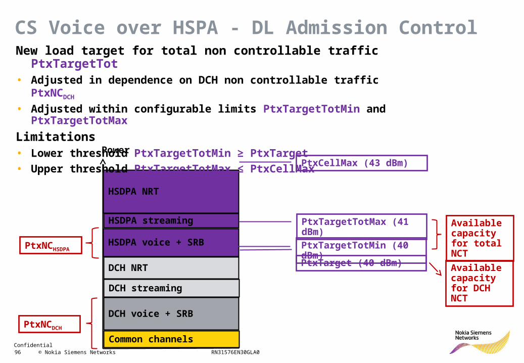
New load target for total non controllable traffic PtxTargetTot• Adjusted in dependence on DCH non controllable traffic PtxNCDCH
• Adjusted within configurable limits PtxTargetTotMin and PtxTargetTotMax
Limitations• Lower threshold PtxTargetTotMin ≥ PtxTarget
• Upper threshold PtxTargetTotMax ≤ PtxCellMax
Available capacity for total NCT
Available capacity for DCH NCT
Confidential 97 © Nokia Siemens Networks RN31576EN30GLA0
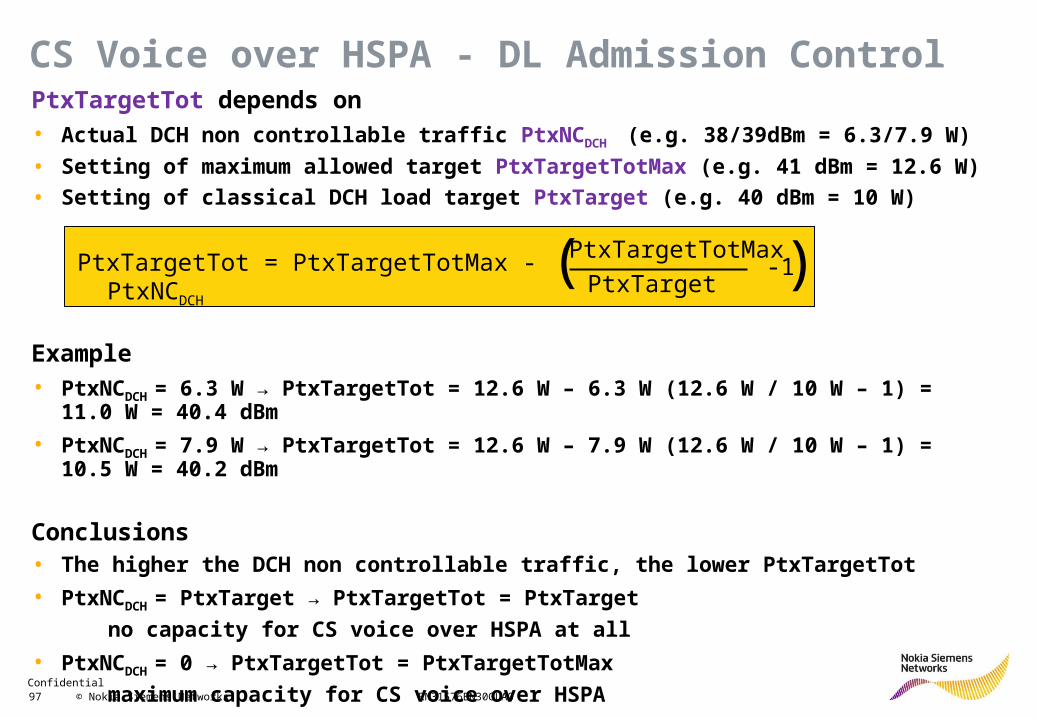
CS Voice over HSPA - DL Admission ControlPtxTargetTot depends on• Actual DCH non controllable traffic PtxNCDCH (e.g. 38/39dBm = 6.3/7.9 W)
• Setting of maximum allowed target PtxTargetTotMax (e.g. 41 dBm = 12.6 W)
• Setting of classical DCH load target PtxTarget (e.g. 40 dBm = 10 W)
Example• PtxNCDCH = 6.3 W → PtxTargetTot = 12.6 W – 6.3 W (12.6 W / 10 W – 1) = 11.0 W = 40.4 dBm
• PtxNCDCH = 7.9 W → PtxTargetTot = 12.6 W – 7.9 W (12.6 W / 10 W – 1) = 10.5 W = 40.2 dBm
Conclusions• The higher the DCH non controllable traffic, the lower PtxTargetTot
• PtxNCDCH = PtxTarget → PtxTargetTot = PtxTarget
no capacity for CS voice over HSPA at all
• PtxNCDCH = 0 → PtxTargetTot = PtxTargetTotMax
maximum capacity for CS voice over HSPA
PtxTargetTot = PtxTargetTotMax - PtxNCDCH
PtxTargetTotMax
PtxTarget-1( )
Confidential 98 © Nokia Siemens Networks RN31576EN30GLA0
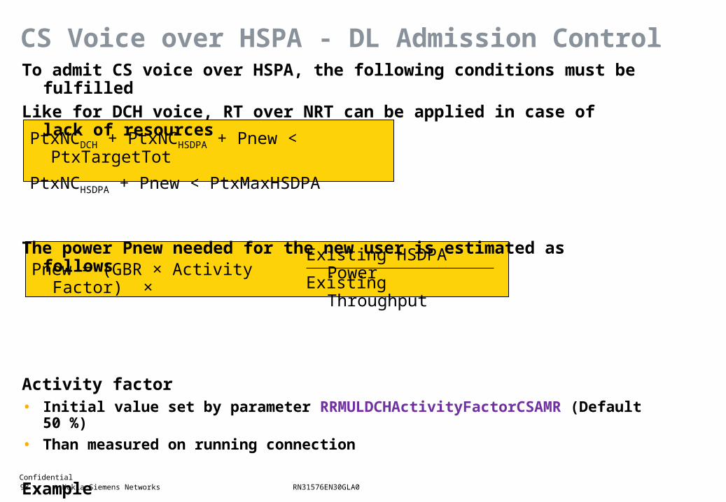
PtxNCDCH + PtxNCHSDPA + Pnew < PtxTargetTot
PtxNCHSDPA + Pnew < PtxMaxHSDPA
Pnew = (GBR × Activity Factor) ×Existing HSDPA Power
Existing Throughput
CS Voice over HSPA - DL Admission ControlTo admit CS voice over HSPA, the following conditions must be fulfilled
Like for DCH voice, RT over NRT can be applied in case of lack of resources
The power Pnew needed for the new user is estimated as follows
Activity factor• Initial value set by parameter RRMULDCHActivityFactorCSAMR (Default 50 %)
• Than measured on running connection
Example• GBR = 12.2 Kbit/s, activity factor = 0.5, HSDPA power = 6 W, throughput = 1 Mbit/s
• Pnew = 12.2 Kbit/s * 0.5 * (6 W / 1000 Kbit/s) = 0.037 W = 16 dBm
Confidential 99 © Nokia Siemens Networks RN31576EN30GLA0
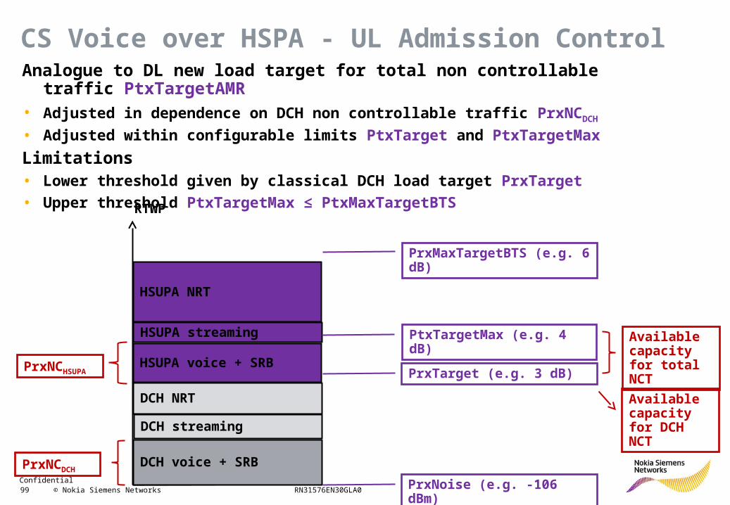
CS Voice over HSPA - UL Admission Control
DCH voice + SRB
DCH streaming
DCH NRT
HSUPA voice + SRB
HSUPA streaming
HSUPA NRT
PrxMaxTargetBTS (e.g. 6 dB)
PtxTargetMax (e.g. 4 dB)
PrxTarget (e.g. 3 dB)
PrxNCDCH
PrxNCHSUPA
RTWP
Analogue to DL new load target for total non controllable traffic PtxTargetAMR• Adjusted in dependence on DCH non controllable traffic PrxNCDCH
• Adjusted within configurable limits PtxTarget and PtxTargetMax
Limitations• Lower threshold given by classical DCH load target PrxTarget
• Upper threshold PtxTargetMax ≤ PtxMaxTargetBTS
Available capacity for total NCT
Available capacity for DCH NCT
PrxNoise (e.g. -106 dBm)
Confidential 100 © Nokia Siemens Networks RN31576EN30GLA0
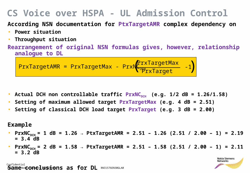
CS Voice over HSPA - UL Admission ControlAccording NSN documentation for PtxTargetAMR complex dependency on• Power situation
• Throughput situation
Rearrangement of original NSN formulas gives, however, relationship analogue to DL
• Actual DCH non controllable traffic PrxNCDCH (e.g. 1/2 dB = 1.26/1.58)
• Setting of maximum allowed target PrxTargetMax (e.g. 4 dB = 2.51)
• Setting of classical DCH load target PrxTarget (e.g. 3 dB = 2.00)
Example• PrxNCDCH = 1 dB = 1.26 → PtxTargetAMR = 2.51 – 1.26 (2.51 / 2.00 – 1) = 2.19 = 3.4 dB
• PrxNCDCH = 2 dB = 1.58 → PtxTargetAMR = 2.51 – 1.58 (2.51 / 2.00 – 1) = 2.11 = 3.2 dB
Same conclusions as for DL
PrxTargetAMR = PrxTargetMax - PrxNCDCH
PrxTargetMax
PrxTarget-1( )
Confidential 101 © Nokia Siemens Networks RN31576EN30GLA0
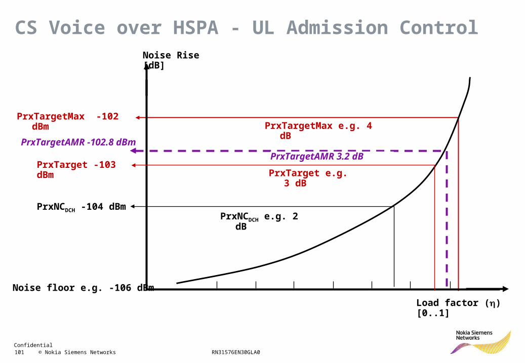
Load factor () [0..1]
Noise Rise [dB]
Noise floor e.g. -106 dBm
PrxTarget -103 dBm
PrxTargetMax -102 dBmPrxTargetMax e.g. 4 dB
PrxNCDCH e.g. 2 dBPrxNCDCH -104 dBm
PrxTargetAMR -102.8 dBm
PrxTarget e.g. 3 dB
CS Voice over HSPA - UL Admission Control
PrxTargetAMR 3.2 dB
Confidential 102 © Nokia Siemens Networks RN31576EN30GLA0
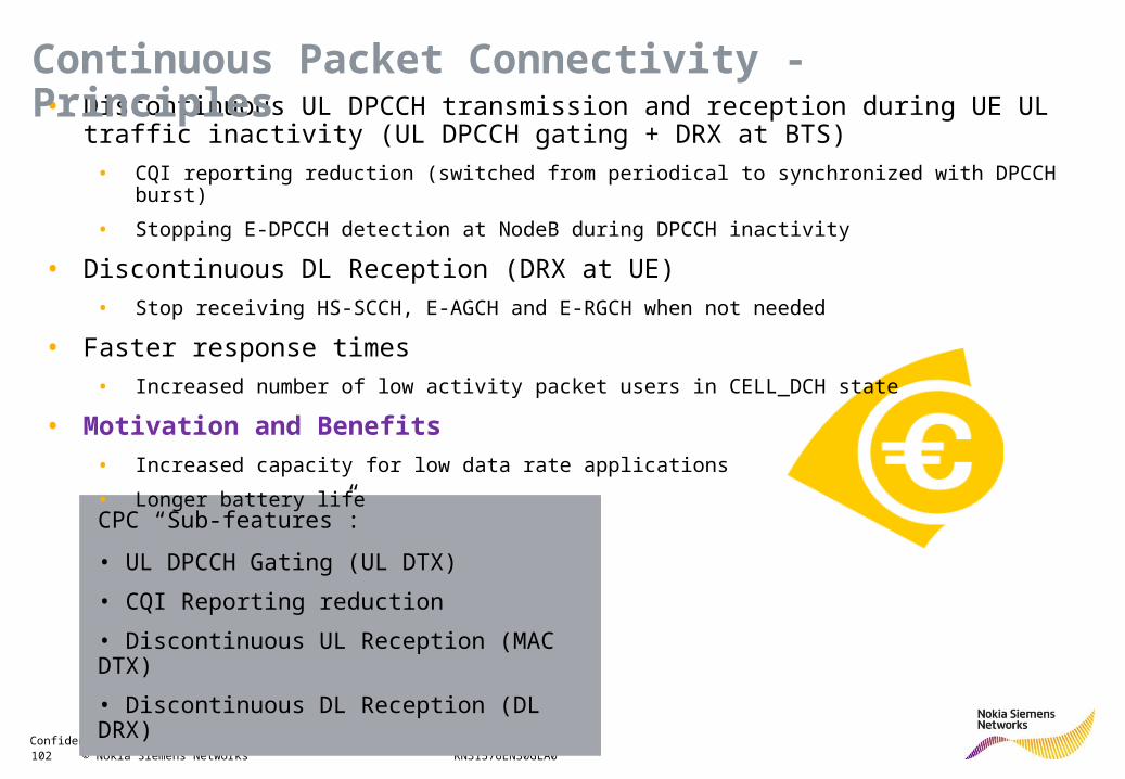
CPC “Sub-features”:
• UL DPCCH Gating (UL DTX)
• CQI Reporting reduction
• Discontinuous UL Reception (MAC DTX)
• Discontinuous DL Reception (DL DRX)
• Discontinuous UL DPCCH transmission and reception during UE UL traffic inactivity (UL DPCCH gating + DRX at BTS)
• CQI reporting reduction (switched from periodical to synchronized with DPCCH burst)
• Stopping E-DPCCH detection at NodeB during DPCCH inactivity
• Discontinuous DL Reception (DRX at UE)
• Stop receiving HS-SCCH, E-AGCH and E-RGCH when not needed
• Faster response times
• Increased number of low activity packet users in CELL_DCH state
• Motivation and Benefits
• Increased capacity for low data rate applications
• Longer battery life
Continuous Packet Connectivity - Principles
Confidential 103 © Nokia Siemens Networks RN31576EN30GLA0
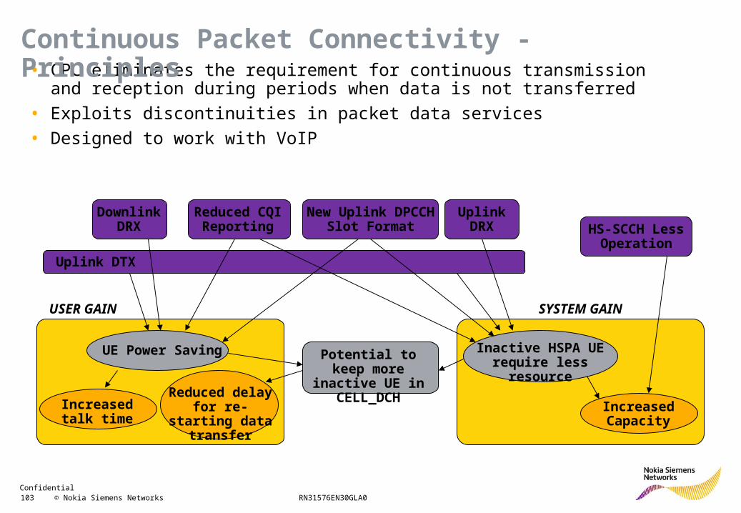
• CPC eliminates the requirement for continuous transmission and reception during periods when data is not transferred
• Exploits discontinuities in packet data services
• Designed to work with VoIP
UE Power Saving Inactive HSPA UE require less resource
Increased talk time
USER GAIN SYSTEM GAIN
Reduced delay for re-starting data transfer
Increased Capacity
Potential to keep more inactive UE
in CELL_DCH
Uplink DTX
Downlink DRX
Reduced CQI Reporting
Uplink DRX
Continuous Packet Connectivity - Principles
HS-SCCH Less Operation
New Uplink DPCCH Slot Format
Confidential 104 © Nokia Siemens Networks RN31576EN30GLA0
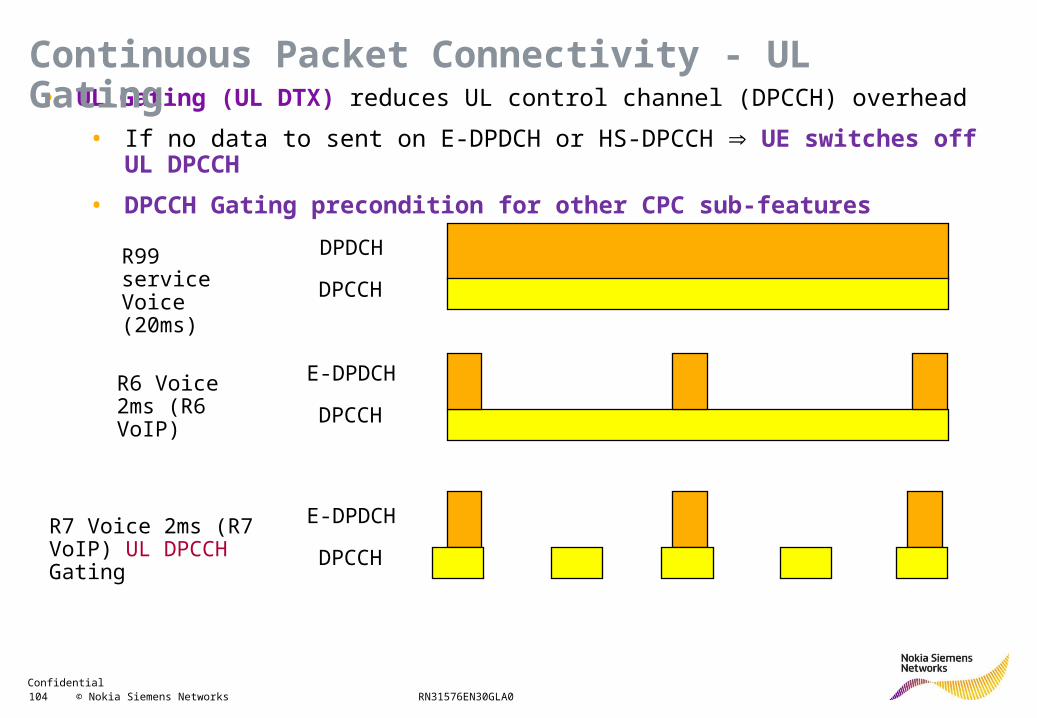
DPDCH
DPCCH
E-DPDCH
DPCCH
E-DPDCH
DPCCH
R99 service Voice (20ms)
R6 Voice 2ms (R6 VoIP)
R7 Voice 2ms (R7 VoIP) UL DPCCH Gating
• UL Gating (UL DTX) reduces UL control channel (DPCCH) overhead
• If no data to sent on E-DPDCH or HS-DPCCH UE switches off UL DPCCH
• DPCCH Gating precondition for other CPC sub-features
Continuous Packet Connectivity - UL Gating
Confidential 105 © Nokia Siemens Networks RN31576EN30GLA0
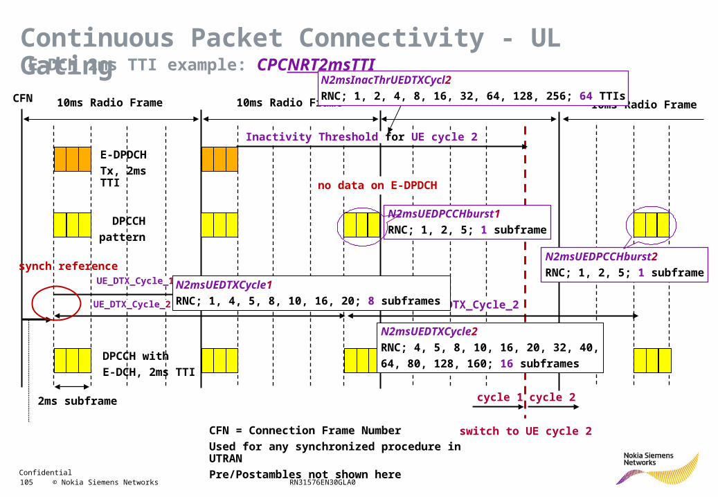
E-DCH 2ms TTI example: CPCNRT2msTTI
10ms Radio Frame 10ms Radio Frame
2ms subframe
CFN
UE_DTX_Cycle_1
UE_DTX_Cycle_2
Inactivity Threshold for UE cycle 2
10ms Radio Frame
UE_DTX_Cycle_2
switch to UE cycle 2
cycle 1 cycle 2
E-DPDCH
Tx, 2ms TTI
DPCCH
pattern
DPCCH with
E-DCH, 2ms TTI
synch reference
CFN = Connection Frame Number
Used for any synchronized procedure in UTRAN
Pre/Postambles not shown here
no data on E-DPDCH
N2msUEDPCCHburst1
RNC; 1, 2, 5; 1 subframe
N2msUEDTXCycle1
RNC; 1, 4, 5, 8, 10, 16, 20; 8 subframes
N2msInacThrUEDTXCycl2
RNC; 1, 2, 4, 8, 16, 32, 64, 128, 256; 64 TTIs
N2msUEDPCCHburst2
RNC; 1, 2, 5; 1 subframe
N2msUEDTXCycle2
RNC; 4, 5, 8, 10, 16, 20, 32, 40,
64, 80, 128, 160; 16 subframes
Continuous Packet Connectivity - UL Gating
Confidential 106 © Nokia Siemens Networks RN31576EN30GLA0
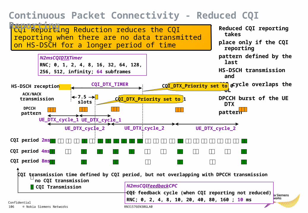
Reduced CQI reporting takes
place only if the CQI reporting
pattern defined by the last
HS-DSCH transmission and
CQI cycle overlaps the UL
DPCCH burst of the UE DTX
pattern
CQI Reporting Reduction reduces the CQI reporting when there are no data transmitted on HS-DSCH for a longer period of time
ACK/NACK transmission
CQI period 2ms
CQI period 4ms
CQI period 8ms
CQI transmission time defined by CQI period, but not overlapping with DPCCH transmissionno CQI transmission
CQI Transmission
DPCCH pattern
UE_DTX_cycle_1 UE_DTX_cycle_1
UE_DTX_cycle_2 UE_DTX_cycle_2
7.5slots
HS-DSCH reception CQI_DTX_TIMER
UE_DTX_cycle_2
CQI_DTX_Priority set to 1
CQI_DTX_Priority set to 0
N2msCQIFeedbackCPC
CQI feedback cycle (when CQI reporting not reduced)
RNC; 0, 2, 4, 8, 10, 20, 40, 80, 160 ; 10 ms
N2msCQIDTXTimer
RNC; 0, 1, 2, 4, 8, 16, 32, 64, 128,
256, 512, infinity; 64 subframes
Continuous Packet Connectivity - Reduced CQI Reporting
Confidential 107 © Nokia Siemens Networks RN31576EN30GLA0
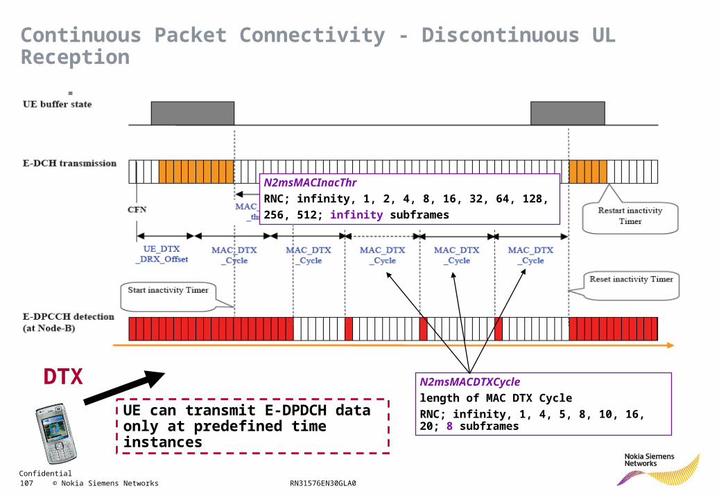
UE can transmit E-DPDCH data only at predefined time instances
N2msMACInacThr
RNC; infinity, 1, 2, 4, 8, 16, 32, 64, 128,
256, 512; infinity subframes
N2msMACDTXCycle
length of MAC DTX Cycle
RNC; infinity, 1, 4, 5, 8, 10, 16, 20; 8 subframes
DTX
Continuous Packet Connectivity - Discontinuous UL Reception
Confidential 108 © Nokia Siemens Networks RN31576EN30GLA0
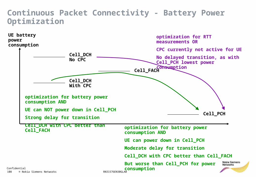
UE battery power consumption
Cell_DCH No CPC
Cell_DCH With CPC
Cell_FACH
Cell_PCH
optimization for RTT measurements OR
CPC currently not active for UE
No delayed transition, as with Cell_PCH lowest power consumption
optimization for battery power consumption AND
UE can power down in Cell_PCH
Moderate delay for transition
Cell_DCH with CPC better than Cell_FACH
But worse than Cell_PCH for power consumption
optimization for battery power consumption AND
UE can NOT power down in Cell_PCH
Strong delay for transition
Cell_DCH with CPC better than Cell_FACH
Continuous Packet Connectivity - Battery Power Optimization
Confidential 109 © Nokia Siemens Networks RN31576EN30GLA0
R99 Features
HSDPA
HSUPA
HSDPA+
HSUPA+
Interference cancellation receiver
Frequency domain equalizer
Capacity Enhancement
Confidential 110 © Nokia Siemens Networks RN31576EN30GLA0
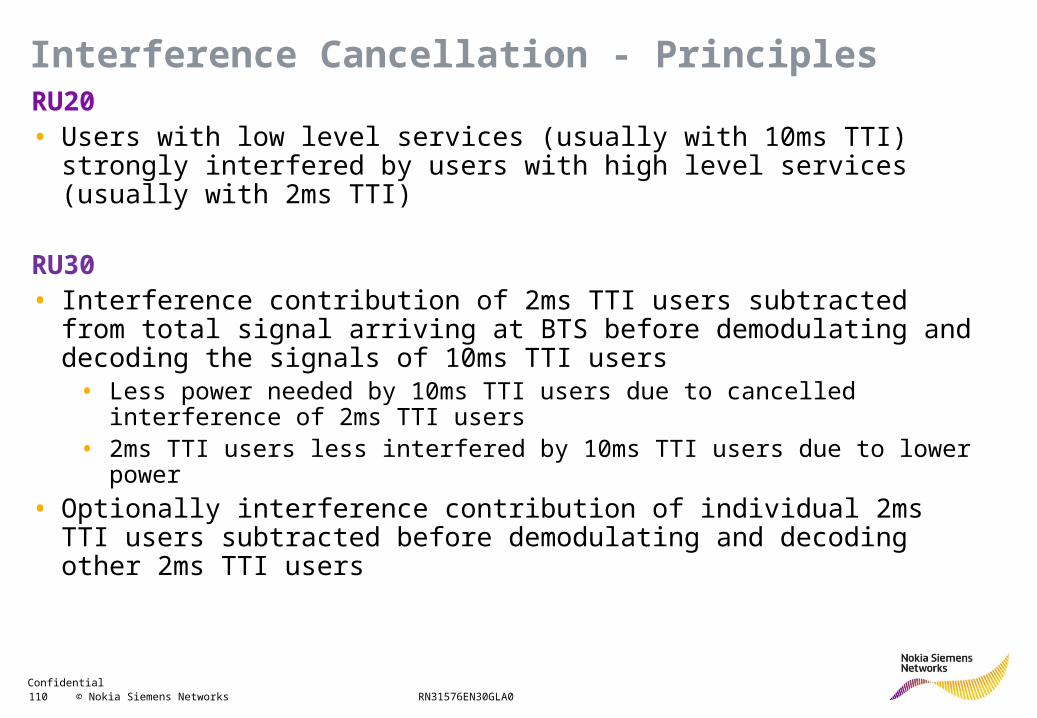
RU20• Users with low level services (usually with 10ms TTI) strongly interfered by
users with high level services (usually with 2ms TTI)
RU30• Interference contribution of 2ms TTI users subtracted from total signal
arriving at BTS before demodulating and decoding the signals of 10ms TTI users
• Less power needed by 10ms TTI users due to cancelled interference of 2ms TTI users
• 2ms TTI users less interfered by 10ms TTI users due to lower power
• Optionally interference contribution of individual 2ms TTI users subtracted before demodulating and decoding other 2ms TTI users
Interference Cancellation - Principles
Confidential 111 © Nokia Siemens Networks RN31576EN30GLA0
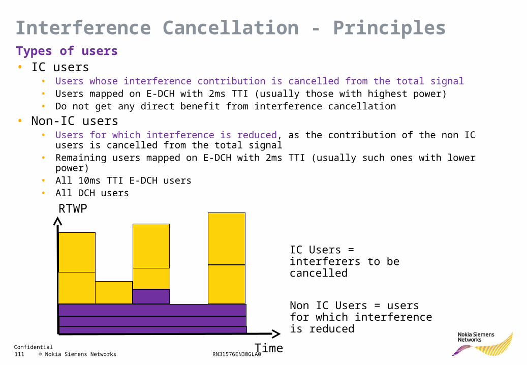
Types of users• IC users
• Users whose interference contribution is cancelled from the total signal• Users mapped on E-DCH with 2ms TTI (usually those with highest power)• Do not get any direct benefit from interference cancellation
• Non-IC users• Users for which interference is reduced, as the contribution of the non IC users is cancelled from the
total signal• Remaining users mapped on E-DCH with 2ms TTI (usually such ones with lower power)• All 10ms TTI E-DCH users• All DCH users
RTWP
Time
IC Users = interferers to be cancelled
Non IC Users = users for which interference is reduced
Interference Cancellation - Principles
Confidential 112 © Nokia Siemens Networks RN31576EN30GLA0
Re-modulate2ms HSUPA
De-modulate2ms HSUPA
2ms HSUPAuser data
Total UL signal from
antenna
De-modulateother
10ms HSUPADCH
user data
2ms HSUPA
Interference cancelled
Non-IC users signal
(Residual signal)
“IC users”
“Non-IC users”
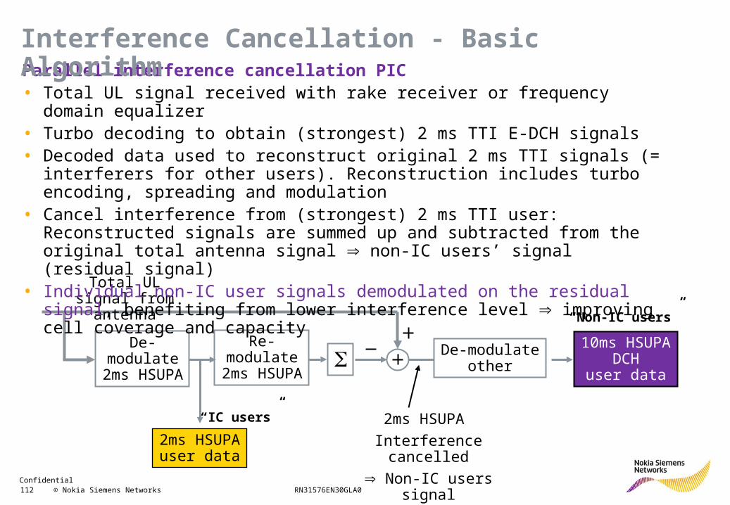
Parallel interference cancellation PIC• Total UL signal received with rake receiver or frequency domain equalizer• Turbo decoding to obtain (strongest) 2 ms TTI E-DCH signals • Decoded data used to reconstruct original 2 ms TTI signals (= interferers for other
users). Reconstruction includes turbo encoding, spreading and modulation• Cancel interference from (strongest) 2 ms TTI user: Reconstructed signals are
summed up and subtracted from the original total antenna signal non-IC users’ signal (residual signal)
• Individual non-IC user signals demodulated on the residual signal, benefiting from lower interference level improving cell coverage and capacity
Interference Cancellation - Basic Algorithm
Confidential 113 © Nokia Siemens Networks RN31576EN30GLA0
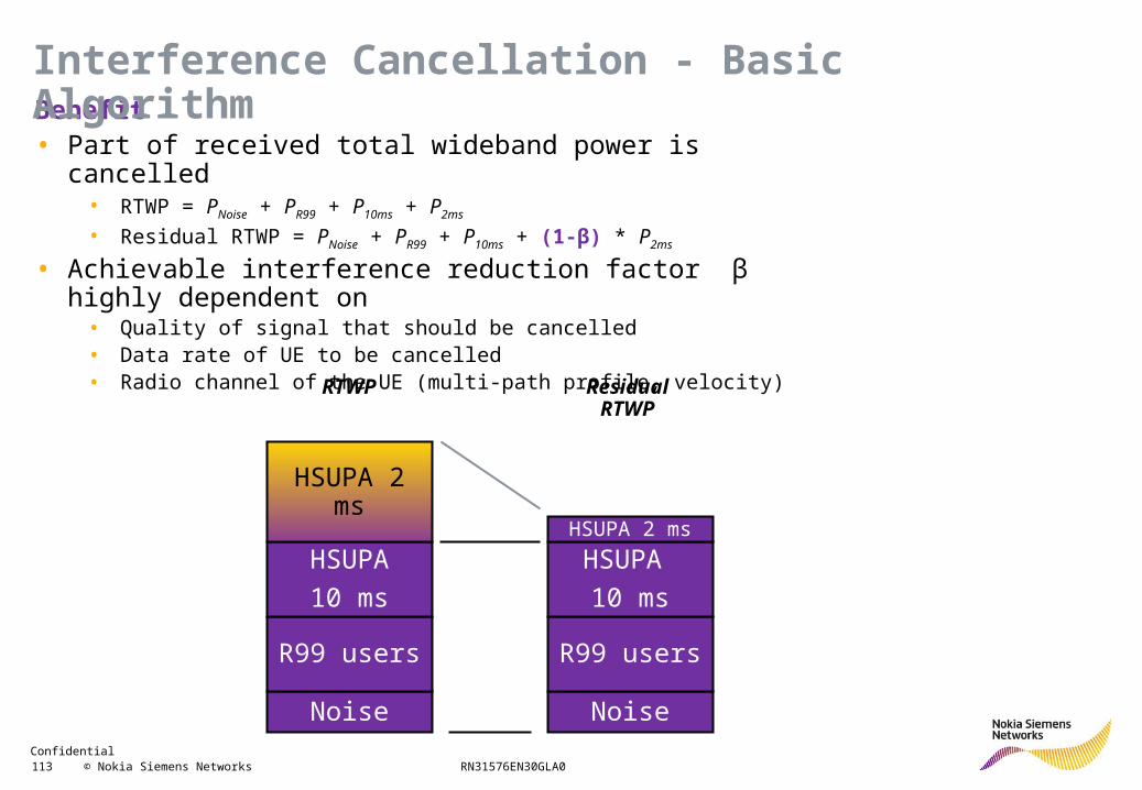
Benefit• Part of received total wideband power is cancelled
• RTWP = PNoise + PR99 + P10ms + P2ms
• Residual RTWP = PNoise + PR99 + P10ms + (1-β) * P2ms
• Achievable interference reduction factor β highly dependent on• Quality of signal that should be cancelled• Data rate of UE to be cancelled• Radio channel of the UE (multi-path profile, velocity)
Noise
R99 users
HSUPA
10 ms
HSUPA 2 ms
Noise
R99 users
HSUPA
10 ms
HSUPA 2 ms
RTWP ResidualRTWP
Interference Cancellation - Basic Algorithm
Confidential 114 © Nokia Siemens Networks RN31576EN30GLA0
Residual stream reconstruction RSR• Basic PIC
• IC users do not benefit directly from the reduced interference • Their signals are demodulated in parallel on the original antenna signal
• Enhanced PIC• Demodulate signals of IC users again after residual signal reconstruction for
these signals (to gain from basic interference cancellation)• Residual Stream Reconstruction RSR
• For each 2 ms TTI user, his individual signal is reconstructed• The reconstructed signal is added to the common residual signal• Interference introduced by 2 ms TTI users canceled from the signals of other 2 ms TTI users
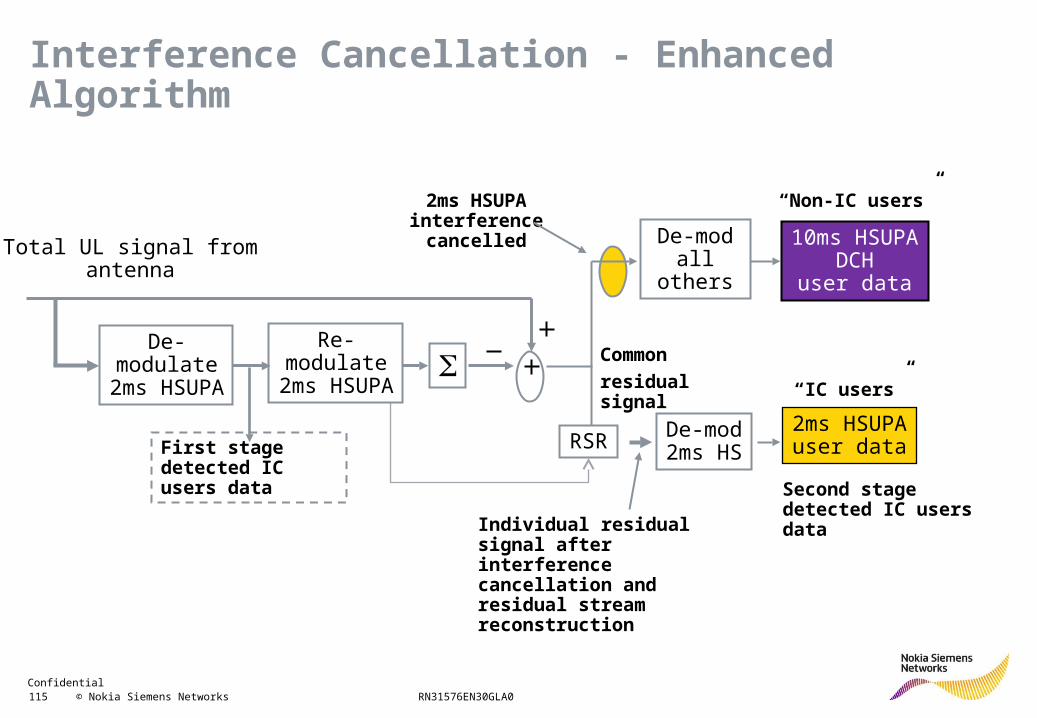
Interference Cancellation - Enhanced Algorithm
Confidential 115 © Nokia Siemens Networks RN31576EN30GLA0
Total UL signal fromantenna
De-modall others
2ms HSUPAinterference
cancelled
RSR De-mod2ms HS
10ms HSUPADCH
user data
“Non-IC users”
2ms HSUPAuser data
“IC users”
Common
residual signal
First stage detected IC users data
Individual residual signal after interference cancellation and residual stream reconstruction
Second stage detected IC users data
Re-modulate2ms HSUPA
De-modulate2ms HSUPA
Interference Cancellation - Enhanced Algorithm
Confidential 116 © Nokia Siemens Networks RN31576EN30GLA0
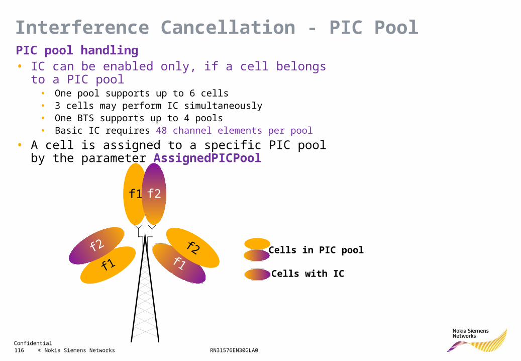
PIC pool handling• IC can be enabled only, if a cell belongs to a PIC pool
• One pool supports up to 6 cells• 3 cells may perform IC simultaneously• One BTS supports up to 4 pools• Basic IC requires 48 channel elements per pool
• A cell is assigned to a specific PIC pool by the parameter AssignedPICPool
f1 f2
f1f1
f2 f2 Cells in PIC pool
Cells with IC
Interference Cancellation - PIC Pool
Confidential 117 © Nokia Siemens Networks RN31576EN30GLA0
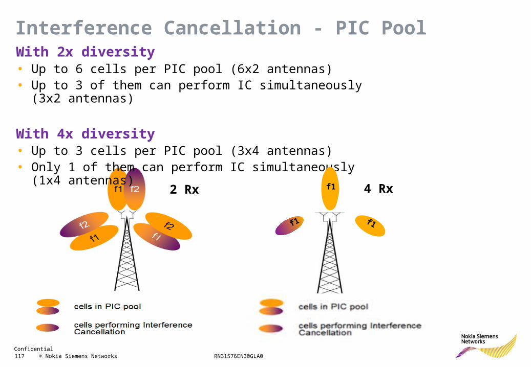
With 2x diversity• Up to 6 cells per PIC pool (6x2 antennas)• Up to 3 of them can perform IC simultaneously (3x2 antennas)
With 4x diversity• Up to 3 cells per PIC pool (3x4 antennas)• Only 1 of them can perform IC simultaneously (1x4 antennas)
f1 f1
f12 Rx 4 Rx
Interference Cancellation - PIC Pool
Confidential 118 © Nokia Siemens Networks RN31576EN30GLA0
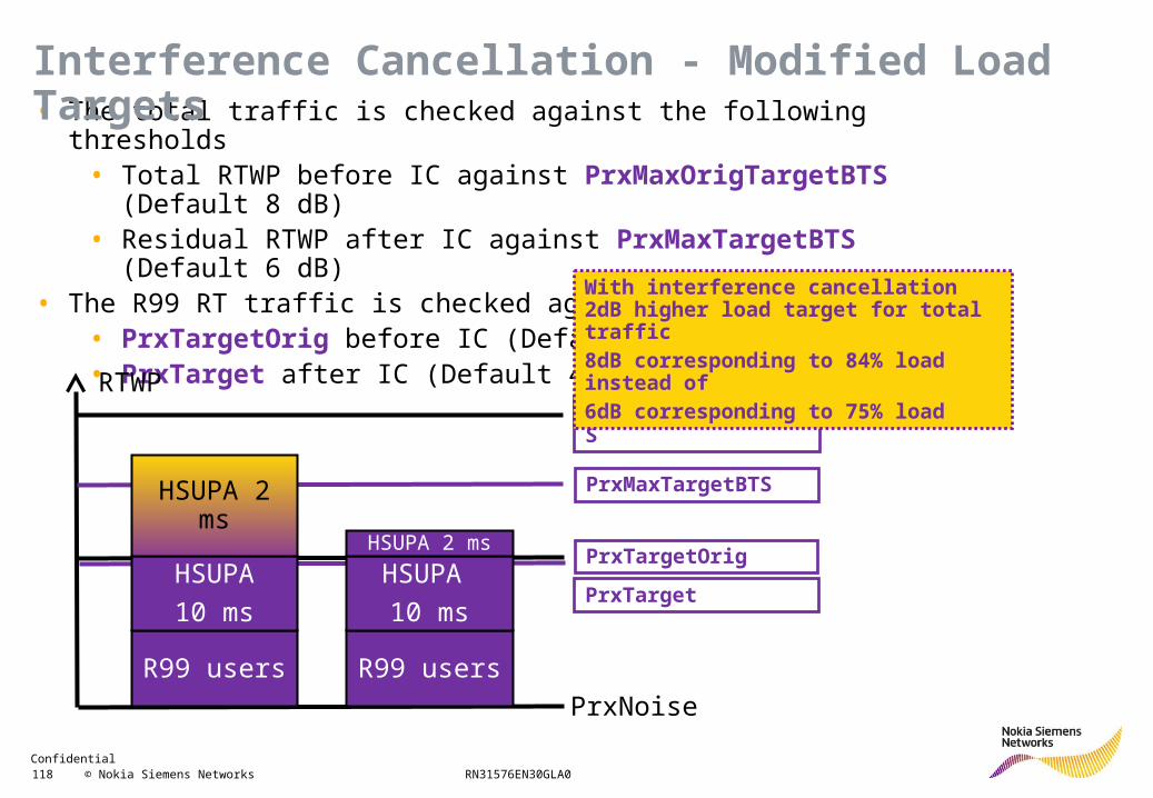
• The total traffic is checked against the following thresholds• Total RTWP before IC against PrxMaxOrigTargetBTS (Default 8 dB)• Residual RTWP after IC against PrxMaxTargetBTS (Default 6 dB)
• The R99 RT traffic is checked against• PrxTargetOrig before IC (Default 4 dB)• PrxTarget after IC (Default 4 dB)
RTWP
PrxNoise
PrxMaxOrigTargetBTS
PrxTargetOrig
PrxMaxTargetBTS
PrxTarget
R99 users
HSUPA
10 ms
HSUPA 2 ms
R99 users
HSUPA
10 ms
HSUPA 2 ms
Interference Cancellation - Modified Load Targets
With interference cancellation 2dB higher load target for total traffic8dB corresponding to 84% load instead of6dB corresponding to 75% load
Confidential 119 © Nokia Siemens Networks RN31576EN30GLA0
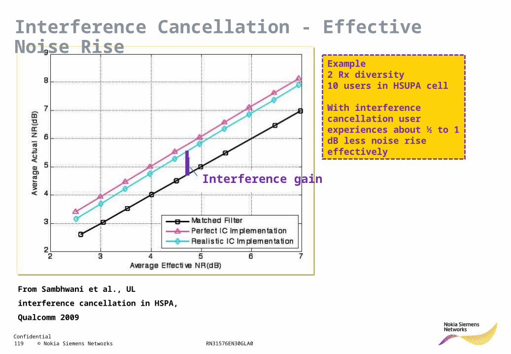
Interference gain
Example2 Rx diversity10 users in HSUPA cell
With interference cancellation user experiences about ½ to 1 dB less noise rise effectively
From Sambhwani et al., UL interference
cancellation in HSPA, Qualcomm 2009
Interference Cancellation - Effective Noise Rise
Confidential 120 © Nokia Siemens Networks RN31576EN30GLA0
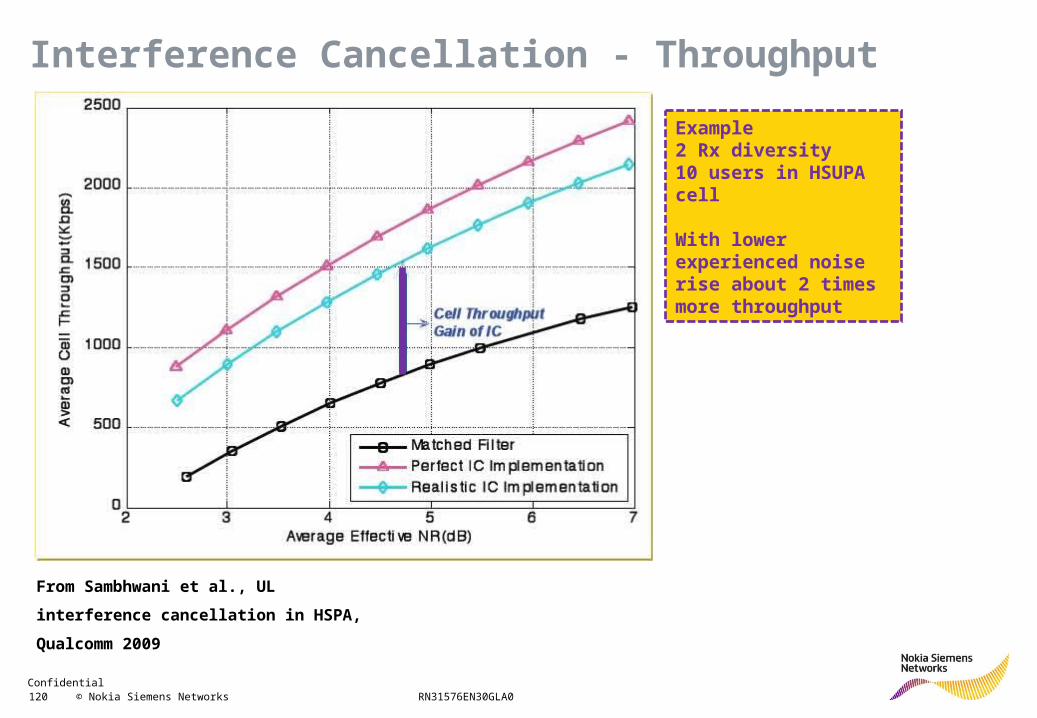
Example2 Rx diversity10 users in HSUPA cell
With lower experienced noise rise about 2 times more throughput
From Sambhwani et al., UL interference
cancellation in HSPA, Qualcomm 2009
Interference Cancellation - Throughput
Confidential 121 © Nokia Siemens Networks RN31576EN30GLA0
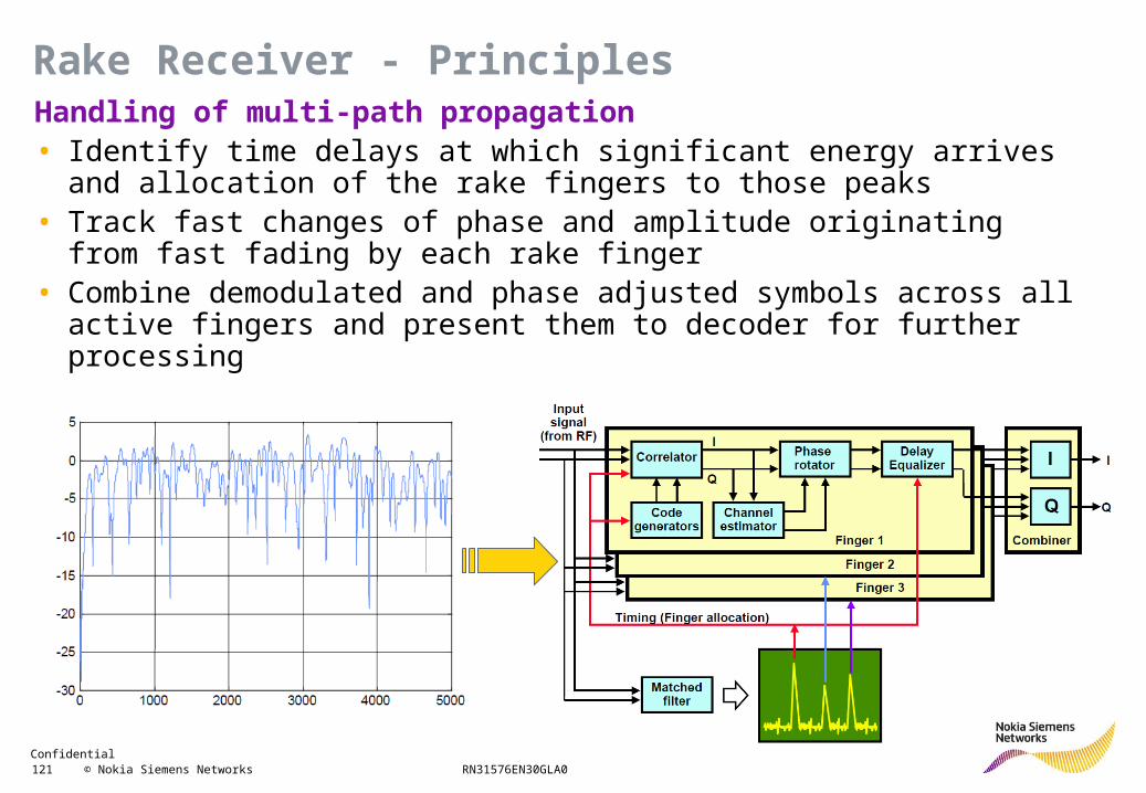
Handling of multi-path propagation• Identify time delays at which significant energy arrives and allocation of the
rake fingers to those peaks• Track fast changes of phase and amplitude originating from fast fading by
each rake finger• Combine demodulated and phase adjusted symbols across all active fingers
and present them to decoder for further processing
Rake Receiver - Principles
Confidential 122 © Nokia Siemens Networks RN31576EN30GLA0
Problem• With HSUPA very short spreading codes (SF down to 2) introduced• Very sensitive to inter-symbol interference introduced by time delay• Maximum data rate of e.g. 5.8 Mbit/s not achieved, saturation at e.g. ≈ 4
Mbit/s even under very good signal-to-noise-ratio conditions
Rake Receiver - Problems
Confidential 123 © Nokia Siemens Networks RN31576EN30GLA0
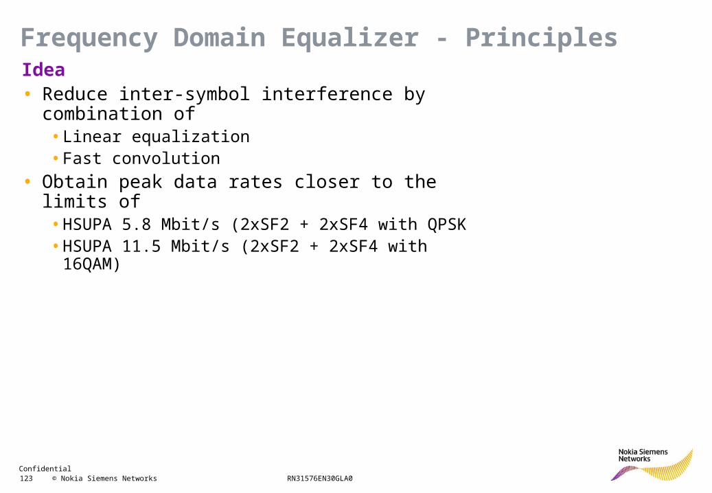
Idea• Reduce inter-symbol interference by combination of
• Linear equalization• Fast convolution
• Obtain peak data rates closer to the limits of• HSUPA 5.8 Mbit/s (2xSF2 + 2xSF4 with QPSK• HSUPA 11.5 Mbit/s (2xSF2 + 2xSF4 with 16QAM)
Frequency Domain Equalizer - Principles
Confidential 124 © Nokia Siemens Networks RN31576EN30GLA0
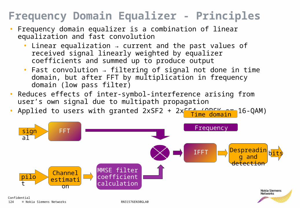
• Frequency domain equalizer is a combination of linear equalization and fast convolution
• Linear equalization → current and the past values of received signal linearly weighted by equalizer coefficients and summed up to produce output
• Fast convolution → filtering of signal not done in time domain, but after FFT by multiplication in frequency domain (low pass filter)
• Reduces effects of inter-symbol-interference arising from user’s own signal due to multipath propagation
• Applied to users with granted 2xSF2 + 2xSF4 (QPSK or 16-QAM)
signal FFT
pilotChannel
estimation
IFFT Despreading and detection
bits
Time domain
Frequency domain
MMSE filter coefficient calculation
Frequency Domain Equalizer - Principles
Confidential 125 © Nokia Siemens Networks RN31576EN30GLA0
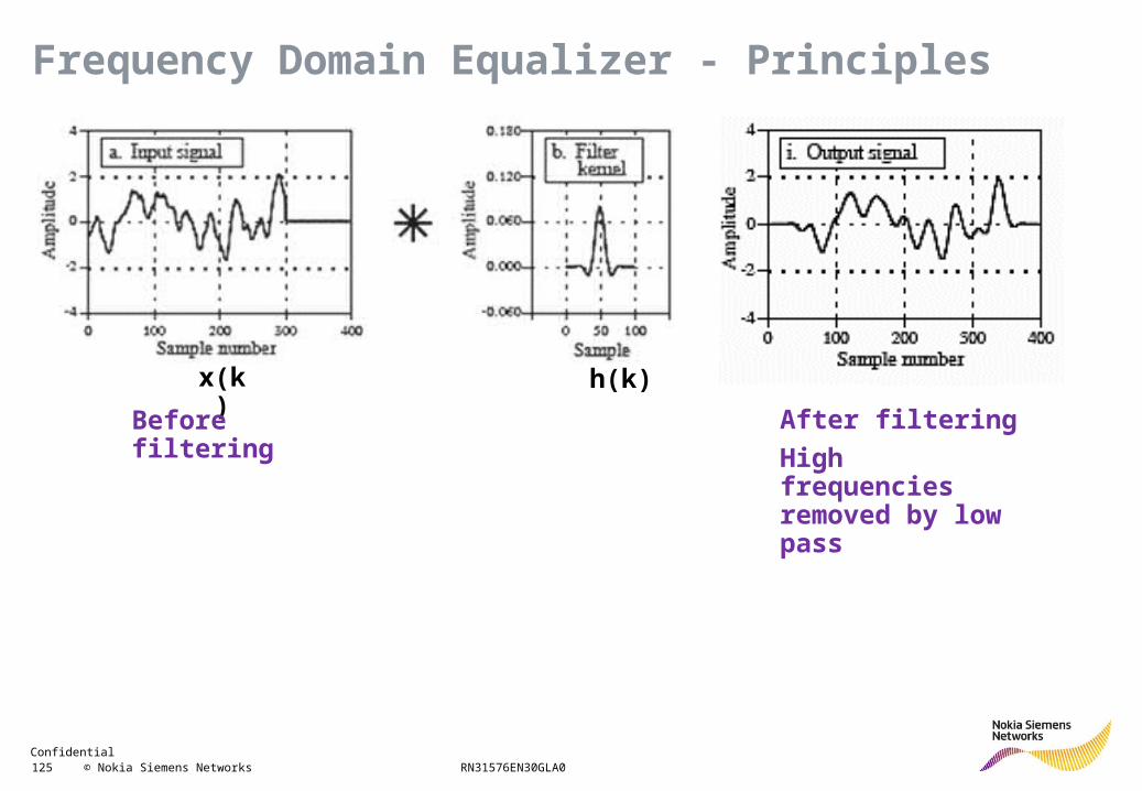
x(k) h(k)
Before filtering
After filtering
High frequencies removed by low pass
Frequency Domain Equalizer - Principles
Confidential 126 © Nokia Siemens Networks RN31576EN30GLA0
non-boosted mode
DPCCH DPCCH
E-DPCCH E-DPCCH
E-DPDCH
E-DPDCH
low E-TFC high E-TFC
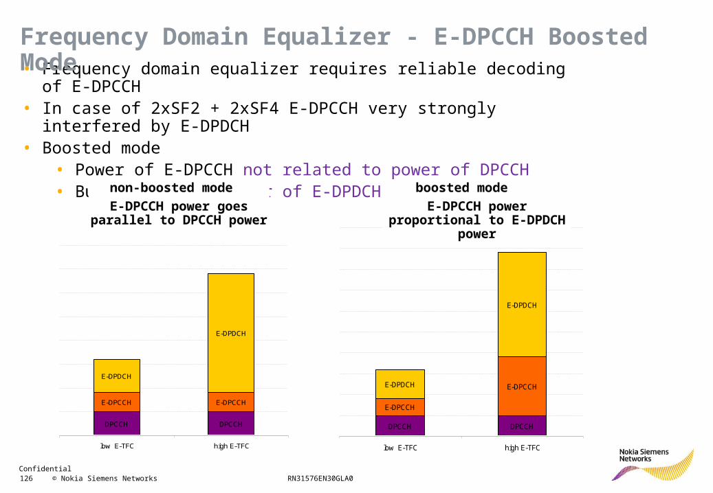
• Frequency domain equalizer requires reliable decoding of E-DPCCH• In case of 2xSF2 + 2xSF4 E-DPCCH very strongly interfered by E-DPDCH• Boosted mode
• Power of E-DPCCH not related to power of DPCCH• But related to power of E-DPDCH
DPCCH DPCCH
E-DPCCH
E-DPCCHE-DPDCH
E-DPDCH
low E-TFC high E-TFC
boosted mode
E-DPCCH power proportional to E-DPDCH power
non-boosted mode
E-DPCCH power goes parallel to DPCCH power
Frequency Domain Equalizer - E-DPCCH Boosted Mode
Confidential 127 © Nokia Siemens Networks RN31576EN30GLA0
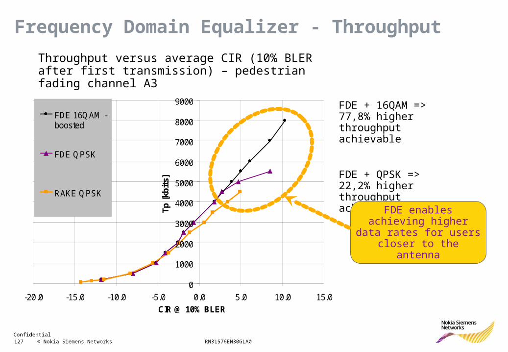
Data rate vs average CIR @ 10% BLER after 1st Tx (Ped A 3)
0
1000
2000
3000
4000
5000
6000
7000
8000
9000
-20.0 -15.0 -10.0 -5.0 0.0 5.0 10.0 15.0
CIR @ 10% BLER
Tp
[kb
its]
FDE 16QAM -boosted
FDE QPSK
RAKE QPSK
Throughput versus average CIR (10% BLER after first transmission) – pedestrian fading channel A3
FDE + 16QAM => 77,8% higher throughput achievable
FDE + QPSK => 22,2% higher throughput achievable
FDE enables achieving higher data rates for users
closer to the antenna
Frequency Domain Equalizer - Throughput