Embed Size (px)
Citation preview
©20
06, S
OMFY
SAS
. All
right
s res
erve
d. R
ef. 5
0463
44-
17/0
7/06
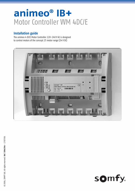
The animeo 4 DC/E Motor Controller 220-240 V AC is designed to control motors of the concept 25 motor range (24 V DC)
Installation guide
animeo® IB+Motor Controller WM 4DC/E
2
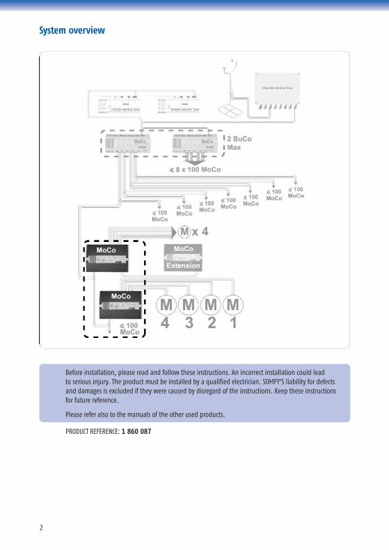
System overview
PRODUCT REFERENCE: 1 860 087
Before installation, please read and follow these instructions. An incorrect installation could lead to serious injury. The product must be installed by a qualified electrician. SOMFY’S liability for defectsand damages is excluded if they were caused by disregard of the instructions. Keep these instructionsfor future reference.
Please refer also to the manuals of the other used products.
3
Table of Contents
0. Definitions 4
1. Mounting 51.1 Choose the optimal location . . . . . . . . . . . . . . . . . . . . . . . . . . . . . . . . . . . . . . . . . . . . . . . . . . . . . . . . . . . . . . . . . . . . . . . . . . . . . . . . . . . . . . . . . . . . . . . . . . . . . . 51.2 Fix the device . . . . . . . . . . . . . . . . . . . . . . . . . . . . . . . . . . . . . . . . . . . . . . . . . . . . . . . . . . . . . . . . . . . . . . . . . . . . . . . . . . . . . . . . . . . . . . . . . . . . . . . . . . . . . . . . . . . . . . . . . . . 51.3 Connect power supply and wiring to other controls (cabling recommendations) . . . . . . . . . . . . . . . . . . . . . . . . . . . . . . . 51.4 Fasten cables with the cable ties . . . . . . . . . . . . . . . . . . . . . . . . . . . . . . . . . . . . . . . . . . . . . . . . . . . . . . . . . . . . . . . . . . . . . . . . . . . . . . . . . . . . . . . . . . . . . . . . . 61.5 Stick the ID number on the building plan . . . . . . . . . . . . . . . . . . . . . . . . . . . . . . . . . . . . . . . . . . . . . . . . . . . . . . . . . . . . . . . . . . . . . . . . . . . . . . . . . . . . . 6
2. Wiring 72.1 Recommended screwdriver . . . . . . . . . . . . . . . . . . . . . . . . . . . . . . . . . . . . . . . . . . . . . . . . . . . . . . . . . . . . . . . . . . . . . . . . . . . . . . . . . . . . . . . . . . . . . . . . . . . . . . . 72.2 Wiring diagram . . . . . . . . . . . . . . . . . . . . . . . . . . . . . . . . . . . . . . . . . . . . . . . . . . . . . . . . . . . . . . . . . . . . . . . . . . . . . . . . . . . . . . . . . . . . . . . . . . . . . . . . . . . . . . . . . . . . . . . . 72.2.1 Push buttons possible to use . . . . . . . . . . . . . . . . . . . . . . . . . . . . . . . . . . . . . . . . . . . . . . . . . . . . . . . . . . . . . . . . . . . . . . . . . . . . . . . . . . . . . . . . . . . . . . . . . . . . . 72.2.2 Motor outputs . . . . . . . . . . . . . . . . . . . . . . . . . . . . . . . . . . . . . . . . . . . . . . . . . . . . . . . . . . . . . . . . . . . . . . . . . . . . . . . . . . . . . . . . . . . . . . . . . . . . . . . . . . . . . . . . . . . . . . . . . . 82.3 Cable specifications . . . . . . . . . . . . . . . . . . . . . . . . . . . . . . . . . . . . . . . . . . . . . . . . . . . . . . . . . . . . . . . . . . . . . . . . . . . . . . . . . . . . . . . . . . . . . . . . . . . . . . . . . . . . . . . . . . 82.4 Check the correct running direction of the end product . . . . . . . . . . . . . . . . . . . . . . . . . . . . . . . . . . . . . . . . . . . . . . . . . . . . . . . . . . . . . . . . . 8
3. Configuration 93.1 Reset / Prog button . . . . . . . . . . . . . . . . . . . . . . . . . . . . . . . . . . . . . . . . . . . . . . . . . . . . . . . . . . . . . . . . . . . . . . . . . . . . . . . . . . . . . . . . . . . . . . . . . . . . . . . . . . . . . . . . . . . 93.1.1 Selection of end product type . . . . . . . . . . . . . . . . . . . . . . . . . . . . . . . . . . . . . . . . . . . . . . . . . . . . . . . . . . . . . . . . . . . . . . . . . . . . . . . . . . . . . . . . . . . . . . . . . . . . 93.1.2 Mode selection DC or DCE . . . . . . . . . . . . . . . . . . . . . . . . . . . . . . . . . . . . . . . . . . . . . . . . . . . . . . . . . . . . . . . . . . . . . . . . . . . . . . . . . . . . . . . . . . . . . . . . . . . . . . . . . . . 93.1.3 Resetting the Motor Controller to factory settings . . . . . . . . . . . . . . . . . . . . . . . . . . . . . . . . . . . . . . . . . . . . . . . . . . . . . . . . . . . . . . . . . . . . . . . . . . 103.2 Set up the Motor Controller . . . . . . . . . . . . . . . . . . . . . . . . . . . . . . . . . . . . . . . . . . . . . . . . . . . . . . . . . . . . . . . . . . . . . . . . . . . . . . . . . . . . . . . . . . . . . . . . . . . . . . . . 103.2.1 Running and tilting times/lengths* . . . . . . . . . . . . . . . . . . . . . . . . . . . . . . . . . . . . . . . . . . . . . . . . . . . . . . . . . . . . . . . . . . . . . . . . . . . . . . . . . . . . . . . . . . . 103.2.2 Intermediate position . . . . . . . . . . . . . . . . . . . . . . . . . . . . . . . . . . . . . . . . . . . . . . . . . . . . . . . . . . . . . . . . . . . . . . . . . . . . . . . . . . . . . . . . . . . . . . . . . . . . . . . . . . . . . . . 113.2.2.1 To set up intermediate position . . . . . . . . . . . . . . . . . . . . . . . . . . . . . . . . . . . . . . . . . . . . . . . . . . . . . . . . . . . . . . . . . . . . . . . . . . . . . . . . . . . . . . . . . . . . . . . . . . 113.2.2.2 To recall an intermediate position . . . . . . . . . . . . . . . . . . . . . . . . . . . . . . . . . . . . . . . . . . . . . . . . . . . . . . . . . . . . . . . . . . . . . . . . . . . . . . . . . . . . . . . . . . . . . . 113.2.2.3 To delete an intermediate position . . . . . . . . . . . . . . . . . . . . . . . . . . . . . . . . . . . . . . . . . . . . . . . . . . . . . . . . . . . . . . . . . . . . . . . . . . . . . . . . . . . . . . . . . . . . . 113.3 Set up of configuration parameters . . . . . . . . . . . . . . . . . . . . . . . . . . . . . . . . . . . . . . . . . . . . . . . . . . . . . . . . . . . . . . . . . . . . . . . . . . . . . . . . . . . . . . . . . . . . . 11
4. Diagnostics 124.1 LEDs of the Motor Controller . . . . . . . . . . . . . . . . . . . . . . . . . . . . . . . . . . . . . . . . . . . . . . . . . . . . . . . . . . . . . . . . . . . . . . . . . . . . . . . . . . . . . . . . . . . . . . . . . . . . . . . . 124.2 Communication indications during the use . . . . . . . . . . . . . . . . . . . . . . . . . . . . . . . . . . . . . . . . . . . . . . . . . . . . . . . . . . . . . . . . . . . . . . . . . . . . . . . . . . 124.3 Small overview of the configuration . . . . . . . . . . . . . . . . . . . . . . . . . . . . . . . . . . . . . . . . . . . . . . . . . . . . . . . . . . . . . . . . . . . . . . . . . . . . . . . . . . . . . . . . . . . 124.4 First level diagnostic . . . . . . . . . . . . . . . . . . . . . . . . . . . . . . . . . . . . . . . . . . . . . . . . . . . . . . . . . . . . . . . . . . . . . . . . . . . . . . . . . . . . . . . . . . . . . . . . . . . . . . . . . . . . . . . . . 124.4.1 Attention LED (�) . . . . . . . . . . . . . . . . . . . . . . . . . . . . . . . . . . . . . . . . . . . . . . . . . . . . . . . . . . . . . . . . . . . . . . . . . . . . . . . . . . . . . . . . . . . . . . . . . . . . . . . . . . . . . . . . . . . . 124.4.2 Indication of the motor(s) concerned by the problem . . . . . . . . . . . . . . . . . . . . . . . . . . . . . . . . . . . . . . . . . . . . . . . . . . . . . . . . . . . . . . . . . . . 13
5. Characteristics 13
4
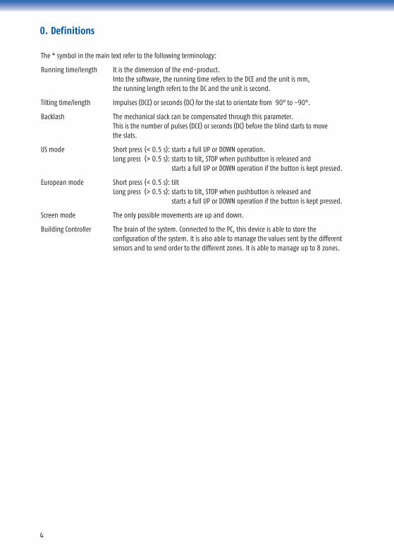
0. Definitions
The * symbol in the main text refer to the following terminology:
Running time/length It is the dimension of the end-product.Into the software, the running time refers to the DCE and the unit is mm, the running length refers to the DC and the unit is second.
Tilting time/length Impulses (DCE) or seconds (DC) for the slat to orientate from 90° to -90°.
Backlash The mechanical slack can be compensated through this parameter. This is the number of pulses (DCE) or seconds (DC) before the blind starts to move the slats.
US mode Short press (< 0.5 s): starts a full UP or DOWN operation.Long press (> 0.5 s): starts to tilt, STOP when pushbutton is released and
starts a full UP or DOWN operation if the button is kept pressed.
European mode Short press (< 0.5 s): tiltLong press (> 0.5 s): starts to tilt, STOP when pushbutton is released and
starts a full UP or DOWN operation if the button is kept pressed.
Screen mode The only possible movements are up and down.
Building Controller The brain of the system. Connected to the PC, this device is able to store theconfiguration of the system. It is also able to manage the values sent by the differentsensors and to send order to the different zones. It is able to manage up to 8 zones.
5
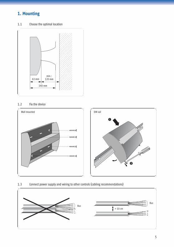
1.2 Fix the device
1.3 Connect power supply and wiring to other controls (cabling recommendations)
1. Mounting
1.1 Choose the optimal location
DIN rail
63 mm
140 mm
min.: 120 mm
Wall mounted
BusBus
> 10 cm
1
2

6
1.4 Fasten cables with the cable ties
1.5 Stick the ID number on the building plan
To identify where the Motor Controller is located:
max.: 6 mm
min
.: 1
00 m
m
1 2
4 53
1 2
3 M1
M2
7
2. Wiring
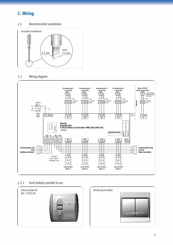
2.1 Recommended screwdriver
2.2 Wiring diagram
2.2.1 Push buttons possible to use
0.4 mmmax.:2.5 mm
junctionbox
L1N
PE
230V50Hz
-mains
C
Up
Down
IB+
2x2x0,8°
max.:1000 m100 MoCo max.
IB+ In
C
Somfy
1860087
4 DC/E Motor Controller WM 220-240V AC
IB+IB+ Out
CIB+
CM1
M1
Res
et/P
rog animeo IB+
21
IB
Ext.
CM2
CM3
CM4
AExt.
B
animeo ID-Nr.:
LL NN EM221 E
M321 E
M421 E
-A1
push buttonMotor 1
C Up
Dow
n
C
Up
Down
IB+
2
M
junctionbox
LW 25 E83Encodermotor 1
31
purp
le
1860
105
RT
S m
odul
e 43
3,42
MH
z
anim
eo
push buttonMotor 2
C Up
Dow
n
push buttonMotor 3
C Up
Dow
n
push buttonMotor 4
C Up
Dow
n
2
M
junctionbox
LW 25 E83Encodermotor 2
31
purp
le
2
M
junctionbox
LW 25 E83Encodermotor 3
31pu
rple
2
M
junctionbox
LW 25 E83Encodermotor 4
31
purp
le
1
M
2junctionbox
M .21 E
Motor 24VDC(without Encoder)
LV 25 B44, B64LW 25, B44, B83LT 28 B73
Communication linefrom
Building Controller*
Communication lineto otherMotor Controllers
alte
rnat
iv
Inteo Centralis IBRef.: 1810138
Double push button
Insulated screwdriver
8
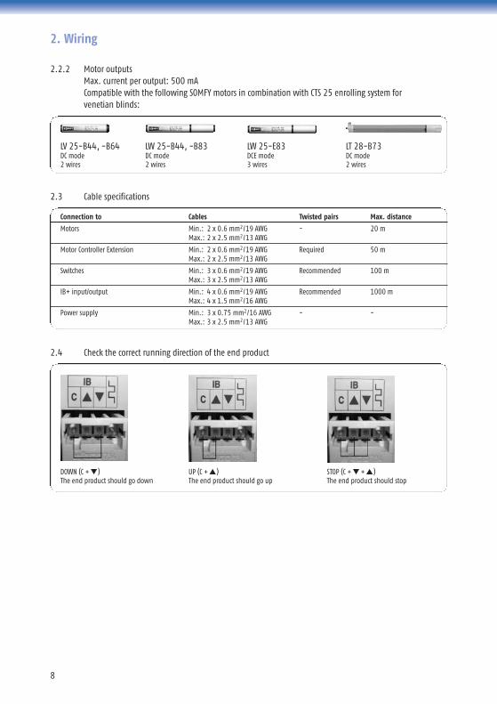
2.2.2 Motor outputsMax. current per output: 500 mACompatible with the following SOMFY motors in combination with CTS 25 enrolling system for venetian blinds:
2.3 Cable specifications
2.4 Check the correct running direction of the end product
LV 25-B44, -B64 LW 25-B44, -B83 LW 25-E83 LT 28-B73DC mode DC mode DCE mode DC mode2 wires 2 wires 3 wires 2 wires
DOWN (C + ▼)The end product should go down
STOP (C + ▼ + ▲)The end product should stop
2. Wiring
Connection to Cables Twisted pairs Max. distance
Motors Min.: 2 x 0.6 mm2/19 AWG - 20 mMax.: 2 x 2.5 mm2/13 AWG
Motor Controller Extension Min.: 2 x 0.6 mm2/19 AWG Required 50 mMax.: 2 x 2.5 mm2/13 AWG
Switches Min.: 3 x 0.6 mm2/19 AWG Recommended 100 mMax.: 3 x 2.5 mm2/13 AWG
IB+ input/output Min.: 4 x 0.6 mm2/19 AWG Recommended 1000 mMax.: 4 x 1.5 mm2/16 AWG
Power supply Min.: 3 x 0.75 mm2/16 AWG - -Max.: 3 x 2.5 mm2/13 AWG
UP (C + ▲)The end product should go up
9
Ext.
IB
Ext.
IB DC
DCE
Ext.
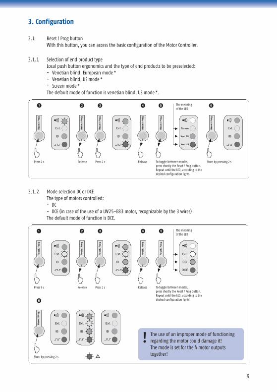
To toggle between modes,press shortly the Reset / Prog button.Repeat until the LED, according to thedesired configuration lights.
Press 9 s Release Press 2 s Release
The meaningof the LED
Res
et /
Pro
g
Res
et /
Pro
g
Res
et /
Pro
g
Res
et /
Pro
g
Res
et /
Pro
g
Ext.
IB
Ext.
IB
Ext.
IB
Store by pressing 2 s
Res
et /
Pro
g3.1 Reset / Prog button
With this button, you can access the basic configuration of the Motor Controller.
3.1.1 Selection of end product typeLocal push button ergonomics and the type of end products to be preselected: - Venetian blind, European mode *- Venetian blind, US mode * - Screen mode *The default mode of function is venetian blind, US mode *.
3.1.2 Mode selection DC or DCEThe type of motors controlled: - DC - DCE (in case of the use of a LW25-E83 motor, recognizable by the 3 wires)The default mode of function is DCE.
The use of an improper mode of functioningregarding the motor could damage it!The mode is set for the 4 motor outputstogether!
!
3. Configuration
IB IB
Ext.Ext. Ext.
IB
Screen
Ven. EU
Ven. US
To toggle between modes,press shortly the Reset / Prog button.Repeat until the LED, according to thedesired configuration lights.
Press 2 s Release Press 2 s Release Store by pressing 2 s
The meaningof the LED
Res
et /
Pro
g
Res
et /
Pro
g
Res
et /
Pro
g
Res
et /
Pro
g
Res
et /
Pro
g
Res
et /
Pro
g
1
1
6
2 3 4 5
2 3 4 5 6
10
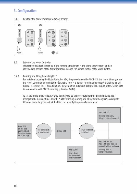
3.2 Set up of the Motor ControllerThis section describes the set up of the running time/length *, the tilting time/length * and anintermediate position of the Motor Controller through the remote control or the wired switch.
3.2.1 Running and tilting times /lengths *For installers knowing the Motor Controller 4DC, the procedure on the 4DC/DCE is the same. When you usethe Motor Controller for the first time (or after a reset ), a default running time/length* of around 35 cm(DCE) or 3 Minutes (DC) is already set up. The default tilt pulses are 110 (for DCE, should fit for 25 mm slatsin combination with CTS 25 enrolling system) or 3s (DC).
To set the tilting times /lengths * only, you have to do the procedure from the beginning and alsoreprogram the running times /lengths *. After learning running and tilting times/lengths *, a complete UP order has to be given so that the blind can identify its upper reference point.
3. Configuration
3.1.3 Resetting the Motor Controller to factory settings
Ext.
IB
Ext.
IB
Ext.
IB
Res
et /
Pro
g
Press 14 s Release
Res
et /
Pro
g
Press STOPon the localpush button 6 s(venetian shouldbe at the top)
Release STOPThe blind startsto move down
Lower end limitis reached
Press STOP < 2 s
Running time is set,tilting time is not changed
1 2
Press DOWN
Slows down the movement(DCE mode only)
Press STOP > = 2 sPress STOP until slats arecompletely tilted backward
Running time & tilting time are set
11
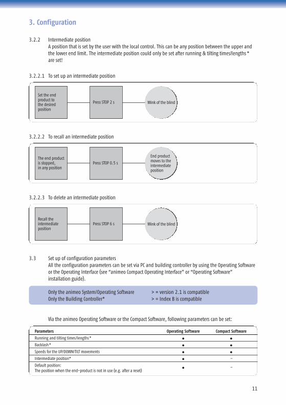
Parameters Operating Software Compact Software
Running and tilting times/lengths* ● ●
Backlash* ● ●
Speeds for the UP/DOWN/TILT movements ● ●
Intermediate position* ● –
Default position: ● –
The position when the end-product is not in use (e.g. after a reset)
Only the animeo System/Operating Software > = version 2.1 is compatibleOnly the Building Controller* > = Index B is compatible
3.2.2 Intermediate positionA position that is set by the user with the local control. This can be any position between the upper andthe lower end limit. The intermediate position could only be set after running & tilting times/lengths * are set!
3. Configuration
3.2.2.2 To recall an intermediate position
3.2.2.1 To set up an intermediate position
3.2.2.3 To delete an intermediate position
3.3 Set up of configuration parametersAll the configuration parameters can be set via PC and building controller by using the Operating Softwareor the Operating Interface (see “animeo Compact Operating Interface” or “Operating Software” installation guide).
Via the animeo Operating Software or the Compact Software, following parameters can be set:
Set the endproduct tothe desiredposition
Press STOP 2 s
The end productis stopped,in any position
Press STOP 0.5 s
Recall theintermediateposition
Press STOP 6 s Wink of the blind
Wink of the blind
End product moves to theintermediateposition
12
4. Diagnostics
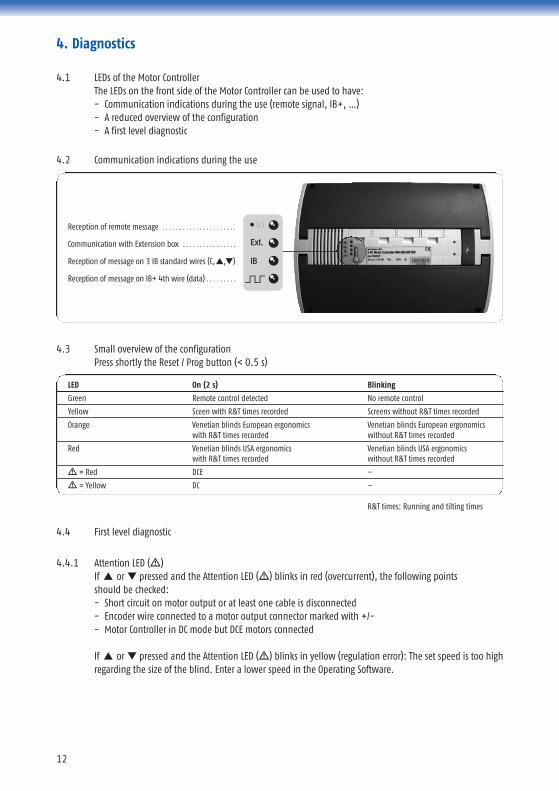
4.2 Communication indications during the use
4.1 LEDs of the Motor ControllerThe LEDs on the front side of the Motor Controller can be used to have:- Communication indications during the use (remote signal, IB+, …)- A reduced overview of the configuration- A first level diagnostic
R&T times: Running and tilting times
LED On (2 s) Blinking
Green Remote control detected No remote control
Yellow Sceen with R&T times recorded Screens without R&T times recorded
Orange Venetian blinds European ergonomics Venetian blinds European ergonomics with R&T times recorded without R&T times recorded
Red Venetian blinds USA ergonomics Venetian blinds USA ergonomicswith R&T times recorded without R&T times recorded
� = Red DCE –
� = Yellow DC –
4.3 Small overview of the configurationPress shortly the Reset / Prog button (< 0.5 s)
Reception of remote message . . . . . . . . . . . . . . . . . . . . . .
Communication with Extension box . . . . . . . . . . . . . . . .
Reception of message on 3 IB standard wires (C,▲,▼)
Reception of message on IB+ 4th wire (data) . . . . . . . . .
4.4 First level diagnostic
4.4.1 Attention LED (�)If ▲ or ▼ pressed and the Attention LED (�) blinks in red (overcurrent), the following points should be checked:- Short circuit on motor output or at least one cable is disconnected - Encoder wire connected to a motor output connector marked with +/-- Motor Controller in DC mode but DCE motors connected
If ▲ or ▼ pressed and the Attention LED (�) blinks in yellow (regulation error): The set speed is too highregarding the size of the blind. Enter a lower speed in the Operating Software.
13
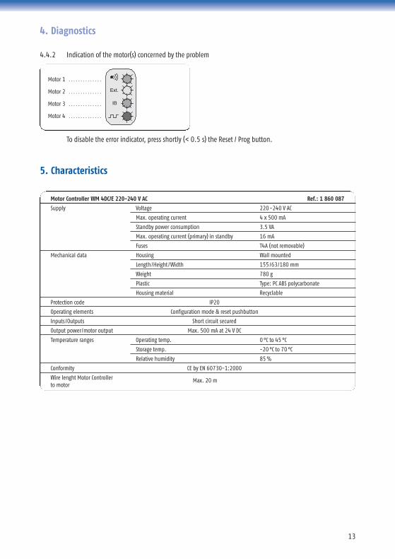
To disable the error indicator, press shortly (< 0.5 s) the Reset / Prog button.
4. Diagnostics
Motor 1 . . . . . . . . . . . . . .
Motor 2 . . . . . . . . . . . . . .
Motor 3 . . . . . . . . . . . . . .
Motor 4 . . . . . . . . . . . . . .
4.4.2 Indication of the motor(s) concerned by the problem
Ext.
IB
5. Characteristics
Motor Controller WM 4DC/E 220-240 V AC Ref.: 1 860 087
Supply Voltage 220-240 V AC
Max. operating current 4 x 500 mA
Standby power consumption 3.5 VA
Max. operating current (primary) in standby 16 mA
Fuses T4A (not removable)
Mechanical data Housing Wall mounted
Length/Height /Width 155/63/180 mm
Weight 780 g
Plastic Type: PC ABS polycarbonate
Housing material Recyclable
Protection code IP20
Operating elements Configuration mode & reset pushbutton
Inputs /Outputs Short circuit secured
Output power/motor output Max. 500 mA at 24 V DC
Temperature ranges Operating temp. 0 °C to 45 °C
Storage temp. -20 °C to 70 °C
Relative humidity 85 %
Conformity CE by EN 60730-1:2000
Wire lenght Motor Controller Max. 20 mto motor
somfy.com
AUSTRIASOMFY GesmbHwww.somfy.atTel.: (43) 662 62 53 08
AUSTRALIASOMFY Pty Limitedwww.somfy.com.auTel.: (61) 2 9638 0744
BELGIUMSOMFY NV SAwww.somfy.beTel.: (32) 2 712 07 70
BRASILSOMFY BRASIL Ltdawww.somfy.com.brTel.: (55-11) 6161 6613
CANADASOMFY ULCwww.somfy.comTel.: (1) 905 564 6445
PR CHINASOMFY China Co Ltd.www.somfy.com.chTel.: (86-21) 6280 9660
CHINASOMFY Shanghaiwww.somfy.com.ch Tel.: (86) 21 6280 9660
CYPRUSSOMFY Middle East Co. Ltd. www.somfy.comTel.: (357) 25 34 55 40
CZECH REPUBLICSOMFY Spol s.r.owww.somfy.czTel.: (420) 296 37 24 86-7
FINLANDSOMFY Finland ABwww.somfy.comTel.: (358) 9 57 130 230
FRANCESOMFY Francewww.somfy.frTel.: (33) 4 50 96 70 96
GERMANYSOMFY GmbHwww.somfy.deTel.: (49) 74 72 93 00
GREECESOMFY Hellas SAwww.somfy.comTel.: (30) 210 614 67 68
HONG KONGSOMFY Co. Ltd.www.somfy.comTel.: (852) 2523 63 39
HUNGARYSOMFY Kftwww.somfy.hu Tel.: (36) 1814 5120
INDIASOMFY India Private Limitedwww.somfy.co.inTel.: (91) 11 51659176
ISRAELSISA HOME AUTOMATION LTDwww.somfy.comTel.: (972)3 952 55 54
ITALYSOMFY Italia S.R.Lwww.somfy.itTel.: (39) 02 48 47 181
JAPANSOMFY K.Kwww.somfy.co.jpTel.: (81) 45 475 07 32
KOREASOMFY JOOwww.somfy.co.krTel.: (82) 2 594 4331
KUWAITSOMFY Kuwaitwww.somfy.com Tel.: (965) 53 39 592
LEBANON SOMFY Lebanonwww.somfy.comTel.: (961) 1 391 224
MEXICO SOMFY MEXICO SA de CDwww.somfy.com.mxTel.: (11) 525 576 3421
NETHERLANDSSOMFY Nederland B.Vwww.somfy.nlTel.: (31) 23 55 44 900
POLANDSOMFY SP Z.O.Owww.somfy.plTel.: (48) 22 818 02 97
(48) 22 618 80 56
PORTUGALSOMFY Portugalwww.somfy.com Tel.: (351) 229 396 840
RUSSIASOMFY LLCwww.somfy.comTel.: (7) 095 3 60 41 86
SINGAPORESOMFY PTE LTDwww.somfy.com.sgTel.: (65) 638 33 855
SPAINSOMFY Espana SAwww.somfy.comTel.: (34) 93 480 09 00
SWEDENSOMFY Nordic ABwww.somfynordic.comTel.: (46) 40 165 900
SWITZERLANDSOMFY AGwww.somfy.ch Tel.: (41) 18 38 40 30
UNITED KINGDOMSOMFY Ltd.www.somfy.co.uk Tel.: (44) 113 391 3030
USASOMFY Systems Inc.www.somfysystems.comTel.: (1) 609 395 1300