Embed Size (px)
Citation preview
8945EDA&8945EDA-D HD EQUALIZING DA MODULE
Instruction Manual
SOFTWARE VERSION 1.0.0
071843600DECEMBER 2005

2 Gecko Flex Frames Instruction Manual
Contacting Grass Valley
Call Centers
Two international Contact Centers (France and US) can be reached 24 hours a day, 7 days a week:From the US: Call 1-800-547-8949 or (530) 478-4148From other countries: Call +800 80 80 20 20 or +33 1 48 25 20 20
Web Site
The Web Site www.thomsongrassvalley.com offers more detailed information.
Warranty registration
Use our convenient on-line registration at www.thomsongrassvalley.com/ProdReg for product warranty registration.
ContentsPreface. . . . . . . . . . . . . . . . . . . . . . . . . . . . . . . . . . . . . . . . . . . . . . . . . . . . . . . . . . . . . . . . . . . . . 5
About This Manual . . . . . . . . . . . . . . . . . . . . . . . . . . . . . . . . . . . . . . . . . . . . . . . . . . . . . . 5
8945EDA and 8945EDA-D Equalizing Distribution AmplifierIntroduction . . . . . . . . . . . . . . . . . . . . . . . . . . . . . . . . . . . . . . . . . . . . . . . . . . . . . . . . . . . . 7
Features. . . . . . . . . . . . . . . . . . . . . . . . . . . . . . . . . . . . . . . . . . . . . . . . . . . . . . . . . . . . . . 7Product Architecture. . . . . . . . . . . . . . . . . . . . . . . . . . . . . . . . . . . . . . . . . . . . . . . . . . . . 8Product Environment . . . . . . . . . . . . . . . . . . . . . . . . . . . . . . . . . . . . . . . . . . . . . . . . . . . 8
Installation . . . . . . . . . . . . . . . . . . . . . . . . . . . . . . . . . . . . . . . . . . . . . . . . . . . . . . . . . . . . . 9Local Configuration . . . . . . . . . . . . . . . . . . . . . . . . . . . . . . . . . . . . . . . . . . . . . . . . . . . . 9Module Placement in the Gecko Flex Frame . . . . . . . . . . . . . . . . . . . . . . . . . . . . . . . . 10
Rear Module Installation . . . . . . . . . . . . . . . . . . . . . . . . . . . . . . . . . . . . . . . . . . . . . 10Front Module Installation . . . . . . . . . . . . . . . . . . . . . . . . . . . . . . . . . . . . . . . . . . . . . 10
Cabling . . . . . . . . . . . . . . . . . . . . . . . . . . . . . . . . . . . . . . . . . . . . . . . . . . . . . . . . . . . . . . . 10Power Up . . . . . . . . . . . . . . . . . . . . . . . . . . . . . . . . . . . . . . . . . . . . . . . . . . . . . . . . . . . . . 12
Operation Indicator LEDs . . . . . . . . . . . . . . . . . . . . . . . . . . . . . . . . . . . . . . . . . . . . . . 12Remote Configuration . . . . . . . . . . . . . . . . . . . . . . . . . . . . . . . . . . . . . . . . . . . . . . . . . . . 14
8900NET Module Information. . . . . . . . . . . . . . . . . . . . . . . . . . . . . . . . . . . . . . . . . . . 14Newton Control Panel Configuration. . . . . . . . . . . . . . . . . . . . . . . . . . . . . . . . . . . . . . 14Web Browser Interface. . . . . . . . . . . . . . . . . . . . . . . . . . . . . . . . . . . . . . . . . . . . . . . . . 158945EDA and 8945EDA-D Links and Web Pages . . . . . . . . . . . . . . . . . . . . . . . . . . . 17
Status Web Page . . . . . . . . . . . . . . . . . . . . . . . . . . . . . . . . . . . . . . . . . . . . . . . . . . . . 17Settings Web Page . . . . . . . . . . . . . . . . . . . . . . . . . . . . . . . . . . . . . . . . . . . . . . . . . . 19Slot Config Web Page. . . . . . . . . . . . . . . . . . . . . . . . . . . . . . . . . . . . . . . . . . . . . . . . 21
Specifications . . . . . . . . . . . . . . . . . . . . . . . . . . . . . . . . . . . . . . . . . . . . . . . . . . . . . . . . . . 23Service . . . . . . . . . . . . . . . . . . . . . . . . . . . . . . . . . . . . . . . . . . . . . . . . . . . . . . . . . . . . . . . 24
Power-up Diagnostics Failure . . . . . . . . . . . . . . . . . . . . . . . . . . . . . . . . . . . . . . . . . . . 24Troubleshooting . . . . . . . . . . . . . . . . . . . . . . . . . . . . . . . . . . . . . . . . . . . . . . . . . . . . . . 24
The Electronic Circuit Breaker . . . . . . . . . . . . . . . . . . . . . . . . . . . . . . . . . . . . . . . . . 24The Tables of Alarms . . . . . . . . . . . . . . . . . . . . . . . . . . . . . . . . . . . . . . . . . . . . . . . . 24
Module Repair . . . . . . . . . . . . . . . . . . . . . . . . . . . . . . . . . . . . . . . . . . . . . . . . . . . . . . . 25Functional Description. . . . . . . . . . . . . . . . . . . . . . . . . . . . . . . . . . . . . . . . . . . . . . . . . . . 26
Input Processing . . . . . . . . . . . . . . . . . . . . . . . . . . . . . . . . . . . . . . . . . . . . . . . . . . . . . . 26Output Processing. . . . . . . . . . . . . . . . . . . . . . . . . . . . . . . . . . . . . . . . . . . . . . . . . . . . . 26Microprocessor . . . . . . . . . . . . . . . . . . . . . . . . . . . . . . . . . . . . . . . . . . . . . . . . . . . . . . . 26Power Supply . . . . . . . . . . . . . . . . . . . . . . . . . . . . . . . . . . . . . . . . . . . . . . . . . . . . . . . . 27
Index . . . . . . . . . . . . . . . . . . . . . . . . . . . . . . . . . . . . . . . . . . . . . . . . . . . . . . . . . . . . . . . . . . . . . . 29
8945EDA and 8945EDA-D Instruction Manual 3

Contents
4 8945EDA and 8945EDA-D Instruction Manual
Preface
About This ManualThis manual describes the features of 8945EDA and 8945EDA-D front modules and their corresponding rear module (8900WE-R) in the Gecko Flex frame. As part of this module family, it is subject to Safety and Regulatory Compliance described in the Gecko Flex frame documentation.
8945EDA and 8945EDA-D Instruction Manual 5
Preface
6 8945EDA and 8945EDA-D Instruction Manual

8945EDA and 8945EDA-D Equalizing Distribution Amplifier
IntroductionThe 8945EDA or 8945EDA-D Wideband Front Equalizing DA provides basic equalization and distribution of a standard definition or high definition signal up to eight outputs over 75 ohm coaxial cable in SD/ASI or HD.
The two models, 8945EDA (single) and 8945EDA-D (dual) must be installed in a Gecko Flex frame.
FeaturesThe features of the 8945EDA and 8945EDA-D include:
� Auto cable equalization for up to 330m of cable in the case of SD and ASI signals and for up to 125m of cable in the case of HD signals,
� Accepts a wide range of standard definition or high definition input signal on one electrical input (two electrical inputs in the case of 8945EDA-D),
� Non-inverted outputs allow distribution of compressed signals for handling such as DVB-ASI,
� Eight HD or SD/ASI electrical outputs,
� Provides a bypass mode for non-supported signal rates,
� Provide alarm (signal presence detection) and status management,
� Supports SNMP MIB reporting basic board alarms, and
� Remote control and monitoring support: web pages, Newton control panel, NetConfig management system.
8945EDA and 8945EDA-D Instruction Manual 7
Introduction
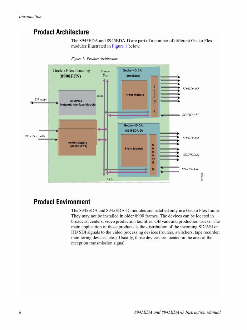
Product ArchitectureThe 8945EDA and 8945EDA-D are part of a number of different Gecko Flex modules illustrated in Figure 1 below.
Figure 1. Product Architecture
Product EnvironmentThe 8945EDA and 8945EDA-D modules are installed only in a Gecko Flex frame. They may not be installed in older 8900 frames. The devices can be located in broadcast centers, video production facilities, OB vans and production trucks. The main application of those products is the distribution of the incoming SD/ASI or HD SDI signals to the video processing devices (routers, switchers, tape recorder, monitoring devices, etc.). Usually, those devices are located in the area of the reception transmission signal.
Frame Bus
Gecko Flex housing
(8900FFN)
Ethernet 8900NET
Network Interface Module
Power Supply
Power Supply
(8900F-PSX)
100 - 240 Volts
±12V
SD/HD/ASI
SD/HD/ASI
SD/HD/ASI
Gecko HD DA
(8945EDA)
Front Module
8
9
0
0
W
E
-
Front Module
8
9
0
0
W
E
-
R
Gecko HD DA
(8945EDA-D)
SD/HD/ASI
SD/HD/ASI
R
8436-01
8 8945EDA and 8945EDA-D Instruction Manual
Installation
InstallationThe front and the rear modules are delivered together as a set.
Installation of the 8945EDA or 8945EDA-D module is a process of:
� Placing the rear module in a rear frame slot,
� Placing the front module in the corresponding front slot, and
� Cabling signal ports.
The 8945EDA and 8945EDA-D modules can be plugged in and removed from a Gecko Flex frame with power on, without disrupting operation on adjacent running modules. When power is applied to the module, LED indicators reflect the initial-ization process (see Power Up on page 12).
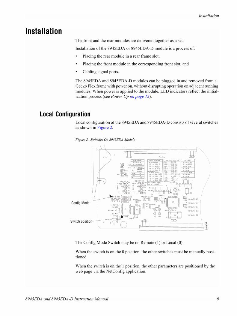
Local ConfigurationLocal configuration of the 8945EDA and 8945EDA-D consists of several switches as shown in Figure 2.
Figure 2. Switches On 8945EDA Module
The Config Mode Switch may be on Remote (1) or Local (0).
When the switch is on the 0 position, the other switches must be manually posi-tioned.
When the switch is on the 1 position, the other parameters are positioned by the web page via the NetConfig application.
Config Mode
8436-02
Switch position
8945EDA and 8945EDA-D Instruction Manual 9
Cabling
Module Placement in the Gecko Flex FrameThere are ten rear and front slot locations in the 2 RU frame to accommodate either analog or digital modules. The 8945EDA or 8945EDA-D module must be plugged into any one of the slots of the Gecko Flex frame.
Rear Module Installation
Note Never remove the screws which maintain the retainer rear shields.
To install a rear module into the frame, follow these steps:
1. Unscrew the blank rear adapter cover without removing the screws.
2. Remove the two retainers and the blank rear adapter cover using a needlenose plier.
3. Insert the corresponding rear module in the slot.
4. Replace both retainer rear shields on each side of the rear module and tighten the screws to secure the rear module.
Front Module InstallationAfter installing the rear module:
1. Unscrew and remove the front cover.
2. Insert the front module in the guides of the corresponding slot.
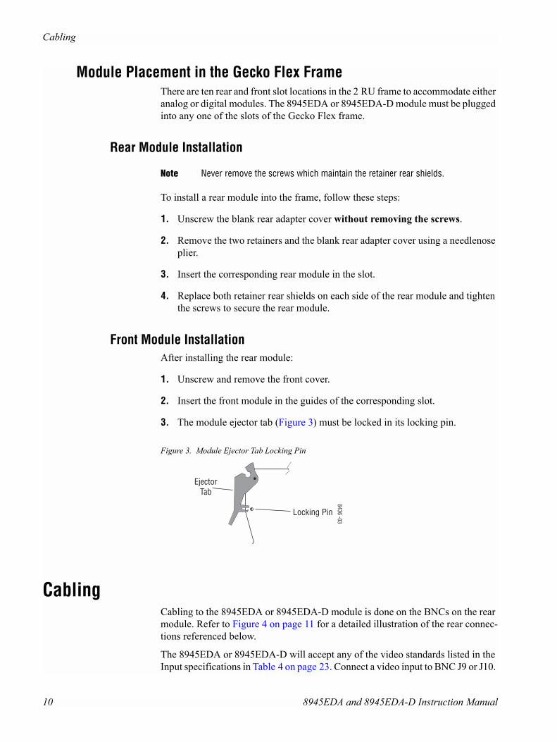
3. The module ejector tab (Figure 3) must be locked in its locking pin.
Figure 3. Module Ejector Tab Locking Pin
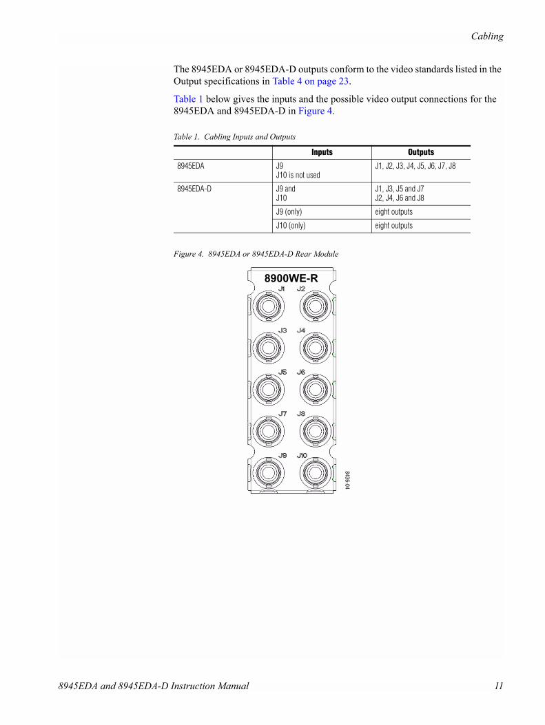
CablingCabling to the 8945EDA or 8945EDA-D module is done on the BNCs on the rear module. Refer to Figure 4 on page 11 for a detailed illustration of the rear connec-tions referenced below.
The 8945EDA or 8945EDA-D will accept any of the video standards listed in the Input specifications in Table 4 on page 23. Connect a video input to BNC J9 or J10.
8436 -03
EjectorTab
Locking Pin
10 8945EDA and 8945EDA-D Instruction Manual
Cabling
The 8945EDA or 8945EDA-D outputs conform to the video standards listed in the Output specifications in Table 4 on page 23.
Table 1 below gives the inputs and the possible video output connections for the 8945EDA and 8945EDA-D in Figure 4.
Figure 4. 8945EDA or 8945EDA-D Rear Module
Table 1. Cabling Inputs and Outputs
Inputs Outputs
8945EDA J9J10 is not used
J1, J2, J3, J4, J5, J6, J7, J8
8945EDA-D J9 and J10
J1, J3, J5 and J7J2, J4, J6 and J8
J9 (only) eight outputs
J10 (only) eight outputs
8900WE-R
8436-04
8945EDA and 8945EDA-D Instruction Manual 11
Power Up
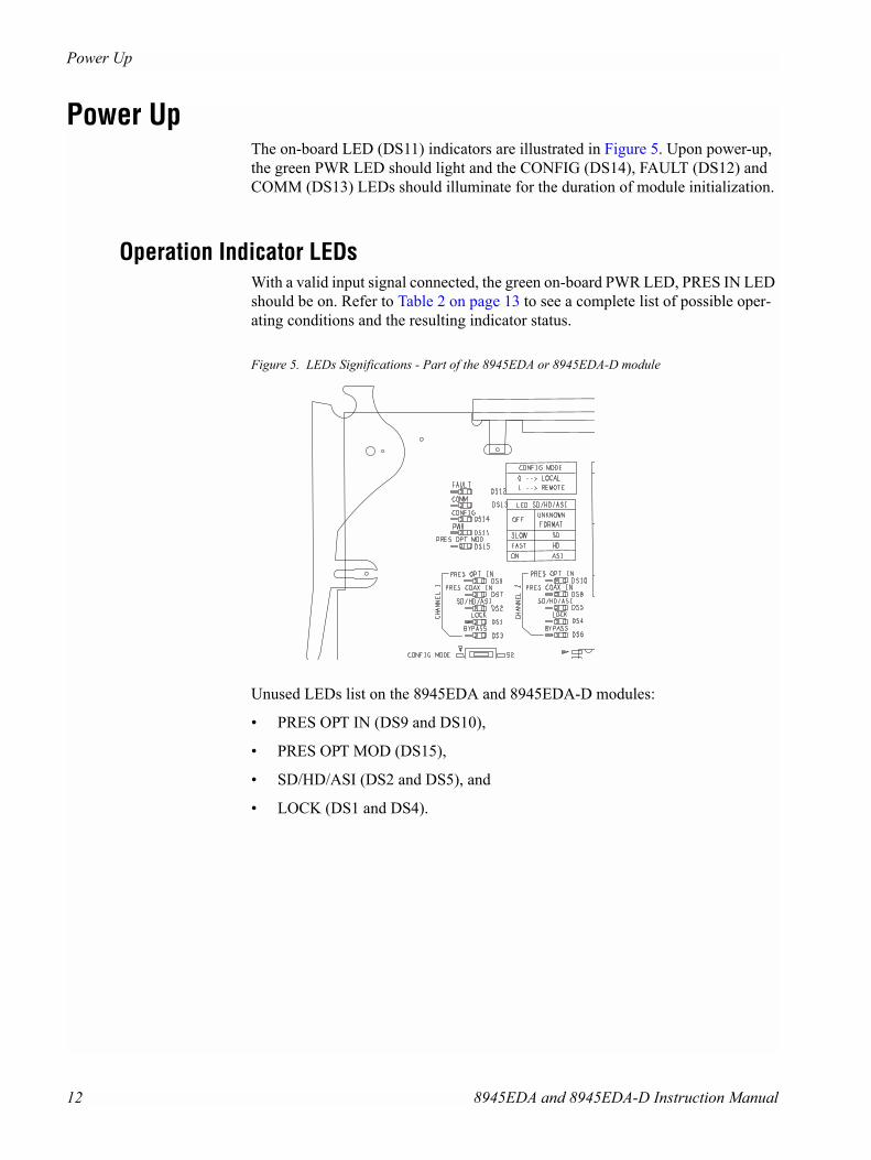
Power UpThe on-board LED (DS11) indicators are illustrated in Figure 5. Upon power-up, the green PWR LED should light and the CONFIG (DS14), FAULT (DS12) and COMM (DS13) LEDs should illuminate for the duration of module initialization.
Operation Indicator LEDsWith a valid input signal connected, the green on-board PWR LED, PRES IN LED should be on. Refer to Table 2 on page 13 to see a complete list of possible oper-ating conditions and the resulting indicator status.
Figure 5. LEDs Significations - Part of the 8945EDA or 8945EDA-D module
Unused LEDs list on the 8945EDA and 8945EDA-D modules:
� PRES OPT IN (DS9 and DS10),
� PRES OPT MOD (DS15),
� SD/HD/ASI (DS2 and DS5), and
� LOCK (DS1 and DS4).
12 8945EDA and 8945EDA-D Instruction Manual
Power Up
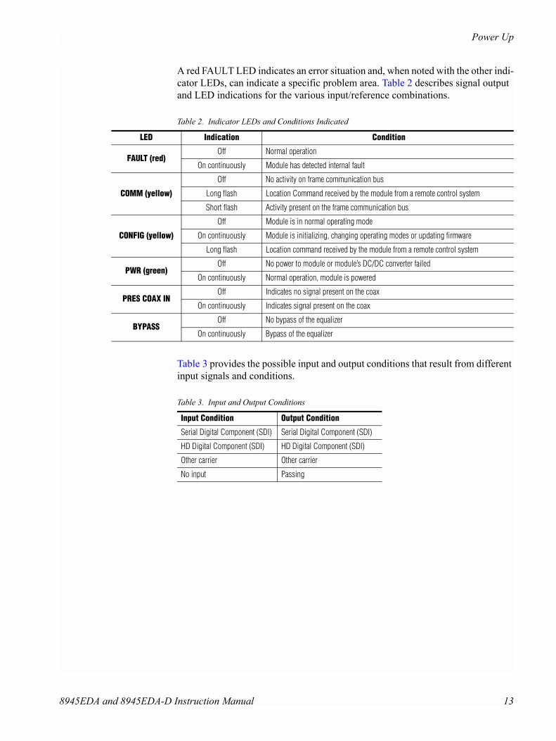
A red FAULT LED indicates an error situation and, when noted with the other indi-cator LEDs, can indicate a specific problem area. Table 2 describes signal output and LED indications for the various input/reference combinations.
Table 3 provides the possible input and output conditions that result from different input signals and conditions.
Table 2. Indicator LEDs and Conditions Indicated
LED Indication Condition
FAULT (red)Off Normal operation
On continuously Module has detected internal fault
COMM (yellow)
Off No activity on frame communication bus
Long flash Location Command received by the module from a remote control system
Short flash Activity present on the frame communication bus
CONFIG (yellow)
Off Module is in normal operating mode
On continuously Module is initializing, changing operating modes or updating firmware
Long flash Location command received by the module from a remote control system
PWR (green)Off No power to module or module’s DC/DC converter failed
On continuously Normal operation, module is powered
PRES COAX INOff Indicates no signal present on the coax
On continuously Indicates signal present on the coax
BYPASSOff No bypass of the equalizer
On continuously Bypass of the equalizer
Table 3. Input and Output Conditions
Input Condition Output Condition
Serial Digital Component (SDI) Serial Digital Component (SDI)
HD Digital Component (SDI) HD Digital Component (SDI)
Other carrier Other carrier
No input Passing
8945EDA and 8945EDA-D Instruction Manual 13

Remote Configuration
Remote Configuration The 8945EDA/8945EDA-D configuration and monitoring can be also performed using a web browser GUI interface or a networked Newton Control Panel when the 8900NET Network Interface module is present in the video frame (Gecko Flex 8900FFN) . Each of these interfaces is described below.
8900NET Module InformationRefer to the 8900NET Network Interface Module Instruction Manual for informa-tion on the 8900NET Network Interface Module and setting up and operating the Gecko Flex 8900 frame network.
Note Upgrade software and instructions for the 8900NET can be downloaded from the Grass Valley web site.
Newton Control Panel ConfigurationA Newton Control Panel (hard or soft version) can be interfaced to the Gecko Flex frame over the local network. Refer to the documentation that accompanies the Newton Modular Control System for installation, configuration, and operation information.
Control panel access offers the following considerations for module configuration and monitoring:
� Ability to separate system level tasks from operation ones, minimizing the potential for on-air mistakes.
� Ability to group modular products�regardless of their physical loca-tions�into logical groups (channels) that you can easily manipulate with user-configured knobs.
� Update software for applicable modules and assign frame and panel IP addresses with the NetConfig Networking application.
� Recommended for real-time control of module configuration parameters, pro-viding the fastest response time.
Note Not all module functions are available with the control panel, such as factory default recalls.
14 8945EDA and 8945EDA-D Instruction Manual
Remote Configuration
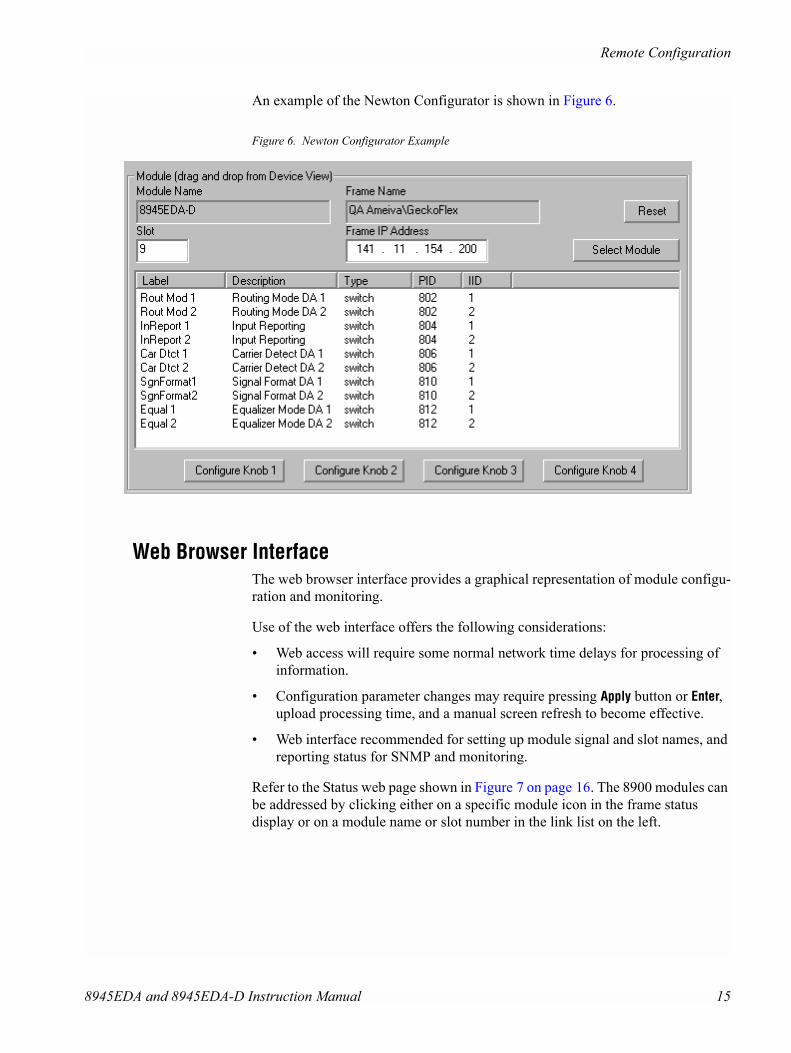
An example of the Newton Configurator is shown in Figure 6.
Figure 6. Newton Configurator Example
Web Browser InterfaceThe web browser interface provides a graphical representation of module configu-ration and monitoring.
Use of the web interface offers the following considerations:
� Web access will require some normal network time delays for processing of information.
� Configuration parameter changes may require pressing Apply button or Enter, upload processing time, and a manual screen refresh to become effective.
� Web interface recommended for setting up module signal and slot names, and reporting status for SNMP and monitoring.
Refer to the Status web page shown in Figure 7 on page 16. The 8900 modules can be addressed by clicking either on a specific module icon in the frame status display or on a module name or slot number in the link list on the left.
8945EDA and 8945EDA-D Instruction Manual 15
Remote Configuration
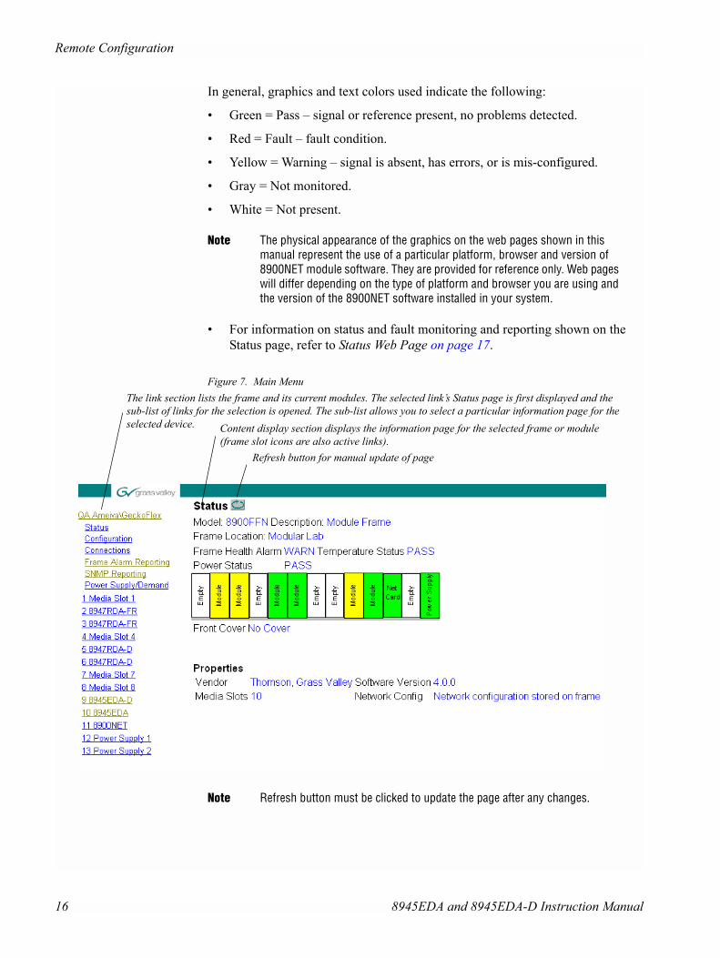
In general, graphics and text colors used indicate the following:
� Green = Pass � signal or reference present, no problems detected.
� Red = Fault � fault condition.
� Yellow = Warning � signal is absent, has errors, or is mis-configured.
� Gray = Not monitored.
� White = Not present.
Note The physical appearance of the graphics on the web pages shown in this manual represent the use of a particular platform, browser and version of 8900NET module software. They are provided for reference only. Web pages will differ depending on the type of platform and browser you are using and the version of the 8900NET software installed in your system.
� For information on status and fault monitoring and reporting shown on the Status page, refer to Status Web Page on page 17.
Figure 7. Main Menu
Note Refresh button must be clicked to update the page after any changes.
The link section lists the frame and its current modules. The selected link�s Status page is first displayed and the sub-list of links for the selection is opened. The sub-list allows you to select a particular information page for the selected device. Content display section displays the information page for the selected frame or module
(frame slot icons are also active links).Refresh button for manual update of page
16 8945EDA and 8945EDA-D Instruction Manual
Remote Configuration
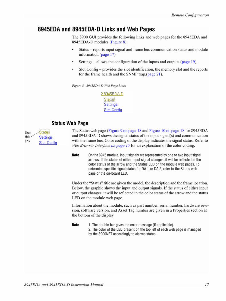
8945EDA and 8945EDA-D Links and Web PagesThe 8900 GUI provides the following links and web pages for the 8945EDA and 8945EDA-D modules (Figure 8):
� Status � reports input signal and frame bus communication status and module information (page 17),
� Settings � allows the configuration of the inputs and outputs (page 19),
� Slot Config � provides the slot identification, the memory slot and the reports for the frame health and the SNMP trap.(page 21).
Figure 8. 8945EDA-D Web Page Links
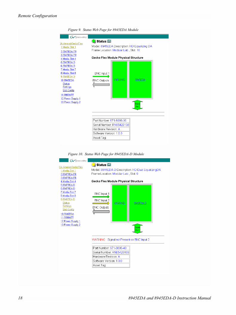
Status Web PageThe Status web page (Figure 9 on page 18 and Figure 10 on page 18 for 8945EDA and 8945EDA-D shows the signal status of the input signal(s) and communication with the frame bus. Color coding of the display indicates the signal status. Refer to Web Browser Interface on page 15 for an explanation of the color coding.
Note On the 8945 module, input signals are represented by one or two input signal arrows. If the status of either input signal changes, it will be reflected in the color status of the arrow and the Status LED on the module web pages. To determine specific signal status for DA 1 or DA 2, refer to the Status web page or the on-board LED.
Under the �Status� title are given the model, the description and the frame location. Below, the graphic shows the input and output signals. If the status of either input or output changes, it will be reflected in the color status of the arrow and the status LED on the module web page.
Information about the module, such as part number, serial number, hardware revi-sion, software version, and Asset Tag number are given in a Properties section at the bottom of the display.
Note 1. The double-bar gives the error message (if applicable).2. The color of the LED present on the top left of each web page is managed by the 8900NET accordingly to alarms status.
Usethislink
8945EDA and 8945EDA-D Instruction Manual 17
Remote Configuration
Figure 9. Status Web Page for 8945EDA Module
Figure 10. Status Web Page for 8945EDA-D Module
18 8945EDA and 8945EDA-D Instruction Manual

Remote Configuration
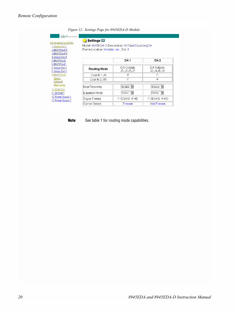
Settings Web PageThe Settings web page for 8945EDA (Figure 11) and 8945EDA-D (Figure 12 on page 20) provides a reporting of signal control for both DA outputs group.This page gives the model, the description and the frame location. The input configura-tion is made on this web page.
The different parameters are explained below:
� Coax 1 and 2 � Choice of J9 or J10 inputs (only J9 for the 8945EDA module) and outputs.
� Input Reporting � Choose between Enable or Disable. The Enable parameter raises alarms towards 8900NET on the input signals (presence of signal). The color of arrows on the Status page will be automatically changed. The Disable parameter will change the color of arrows on the Status web page to grey to show they are not being monitored or reported to upper level control devices.
� Equalizer Mode � If the Active parameter is chosen, the equalizer is used. Oth-erwise, the equalizer is bypass.
� Signal Format � Indicates the input signal format. The choice is between SD/ASI and HD. This parameter acts on the rise and fall time value.
� Carrier Detect � Indicates the input signal detection of DA1 or DA2 (for 8945EDA-D).
Figure 11. Settings Page for 8945EDA Module
Usethislink
8945EDA and 8945EDA-D Instruction Manual 19
Remote Configuration
Figure 12. Settings Page for 8945EDA-D Module
Note See table 1 for routing mode capabilities.
20 8945EDA and 8945EDA-D Instruction Manual
Remote Configuration
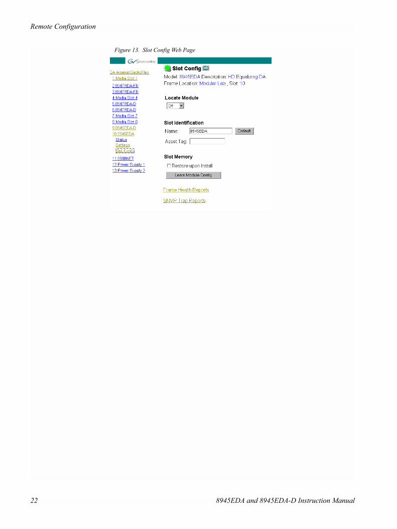
Slot Config Web PageUse the Slot Config web page (Figure 13 on page 22) to perform the following functions on the module:
� Locate Module � selecting the Flash pulldown button flashes the yellow COMM LED on the front of the module so it can be located in the frame.
� Slot Identification � You may identify the module by typing a specific name in the Name field. The assigned name is stored on the 8900NET module and travels with the 8900NET module if it is moved to another frame. Select Default to enter the factory default module name.
An asset identification may be entered in the Asset Tag field. This will appear on the module Status web page and in the NetConfig inventory report.
� Slot Memory � the slot configuration for each media module is automatically saved periodically (once an hour) to the 8900NET module in that frame. You may also select the Learn Module Config button at any time to save the current configuration for this slot. The configuration is saved on the 8900NET module. If the 8900NET module is removed or powered down, the stored configura-tions are not saved.
When the Restore upon Install box has been checked, the current configuration saved to this slot is saved as slot memory. When the current module is removed and another module of the same type is installed, the configuration saved to the 8900NET module will be downloaded to the new module. The box must be checked before the current module with the saved configuration is removed.
� Frame Health Reporting � In the page of this function, the boxes must be checked. When there is a hardware problem the 8900NET software raises an alarm.
� Slot SNMP Trap Reports � displayed only when the SNMP Agent software has been installed on the 8900NET module. Slot SNMP traps can be enabled only when the hardware switches for Module Fault reporting and Asynchronous Status reporting are enabled on the 8900NET module (dipswitch S1 segment 5 and dipswitch S2 segment 1).
The enabled SNMP traps will be reported to any SNMP manager that is iden-tified as an SNMP Report Destination in 8900NET configuration. Trap severity is read-only hard-coded information that is interpreted and responded to by the SNMP Manager software configuration.
Usethislink
8945EDA and 8945EDA-D Instruction Manual 21
Remote Configuration
Figure 13. Slot Config Web Page
22 8945EDA and 8945EDA-D Instruction Manual
Specifications
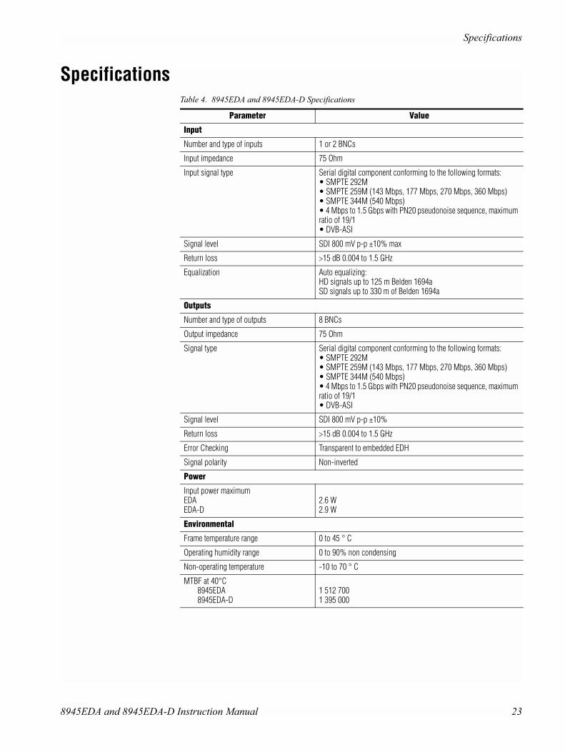
SpecificationsTable 4. 8945EDA and 8945EDA-D Specifications
Parameter Value
Input
Number and type of inputs 1 or 2 BNCs
Input impedance 75 Ohm
Input signal type Serial digital component conforming to the following formats:• SMPTE 292M• SMPTE 259M (143 Mbps, 177 Mbps, 270 Mbps, 360 Mbps)• SMPTE 344M (540 Mbps)• 4 Mbps to 1.5 Gbps with PN20 pseudonoise sequence, maximum ratio of 19/1• DVB-ASI
Signal level SDI 800 mV p-p ±10% max
Return loss >15 dB 0.004 to 1.5 GHz
Equalization Auto equalizing:HD signals up to 125 m Belden 1694aSD signals up to 330 m of Belden 1694a
Outputs
Number and type of outputs 8 BNCs
Output impedance 75 Ohm
Signal type Serial digital component conforming to the following formats:• SMPTE 292M• SMPTE 259M (143 Mbps, 177 Mbps, 270 Mbps, 360 Mbps)• SMPTE 344M (540 Mbps)• 4 Mbps to 1.5 Gbps with PN20 pseudonoise sequence, maximum ratio of 19/1• DVB-ASI
Signal level SDI 800 mV p-p ±10%
Return loss >15 dB 0.004 to 1.5 GHz
Error Checking Transparent to embedded EDH
Signal polarity Non-inverted
Power
Input power maximumEDAEDA-D
2.6 W2.9 W
Environmental
Frame temperature range 0 to 45 ° C
Operating humidity range 0 to 90% non condensing
Non-operating temperature -10 to 70 ° C
MTBF at 40°C8945EDA8945EDA-D
1 512 7001 395 000
8945EDA and 8945EDA-D Instruction Manual 23

Service
ServiceThe 8945EDA modules make extensive use of surface-mount technology and pro-grammed parts to achieve compact size and adherence to demanding technical specifications. Circuit modules should not be serviced in the field unless otherwise directed by Customer Service.
Power-up Diagnostics FailureIf the module has not passed self-diagnostics, do not attempt to troubleshoot. Return the unit to Grass Valley (see Module Repair on page 25).
Troubleshooting
The Electronic Circuit BreakerThe electronic circuit breaker works during a fault condition or an overcurrent which stops the module.
Remove the module and replace it in the frame. If the problem persists, please refer to the Grass Valley Customer Service.
The Tables of Alarms
The table below describes the different type of alarms:
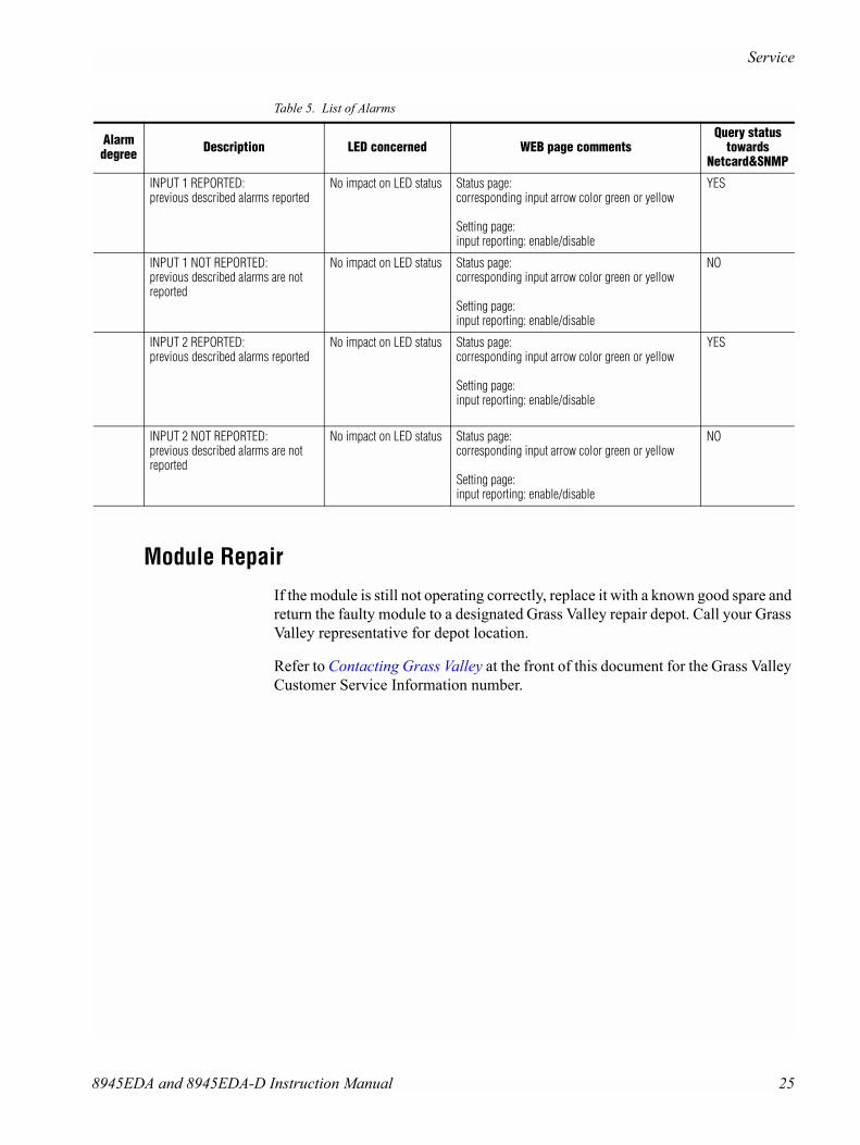
Table 5. List of Alarms
Alarm degree Description LED concerned WEB page comments
Query statustowards
Netcard&SNMP
High Hardware failure: no application code Fault red on Boot status page: Only this page is visible, software is downloading
High Bad rear module: if optical rear type on EDA and EDA-D
Fault: flashing Status page: bad rear modulePID_RES_DEVICE_STATUS: rear module in yellow color (green if OK)
YES
High Electrical signal detect on DA 1 ( DUAL or single mode2) only when electric selected
PRES COAX IN 1 STATUS PAGE:elec input arrow is green/red/yellowSETTING page:carrier detect : present / not present
YES
High Electrical signal detect on DA 2( DUAL or single mode1) only when electric selected
PRES COAX IN 2 STATUS PAGE:elec input arrow are green/red/yellowSETTING page:carrier detect : present / not present
YES
Equalizer 1 bypassed Bypass SETTING page:equalizer mode : BYPASS
No
Equalizer 2 bypassed Bypass SETTING page:equalizer mode : BYPASS
No
24 8945EDA and 8945EDA-D Instruction Manual
Service
Module RepairIf the module is still not operating correctly, replace it with a known good spare and return the faulty module to a designated Grass Valley repair depot. Call your Grass Valley representative for depot location.
Refer to Contacting Grass Valley at the front of this document for the Grass Valley Customer Service Information number.
INPUT 1 REPORTED:previous described alarms reported
No impact on LED status Status page:corresponding input arrow color green or yellow
Setting page:input reporting: enable/disable
YES
INPUT 1 NOT REPORTED:previous described alarms are not reported
No impact on LED status Status page:corresponding input arrow color green or yellow
Setting page:input reporting: enable/disable
NO
INPUT 2 REPORTED:previous described alarms reported
No impact on LED status Status page:corresponding input arrow color green or yellow
Setting page:input reporting: enable/disable
YES
INPUT 2 NOT REPORTED:previous described alarms are not reported
No impact on LED status Status page:corresponding input arrow color green or yellow
Setting page:input reporting: enable/disable
NO
Table 5. List of Alarms
Alarm degree Description LED concerned WEB page comments
Query statustowards
Netcard&SNMP
8945EDA and 8945EDA-D Instruction Manual 25
Functional Description
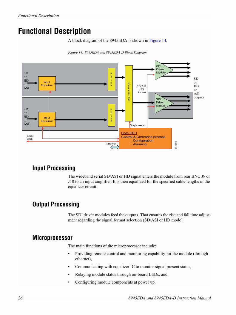
Functional DescriptionA block diagram of the 8945EDA is shown in Figure 14.
Figure 14. 8945EDA and 8945EDA-D Block Diagram
Input ProcessingThe wideband serial SD/ASI or HD signal enters the module from rear BNC J9 or J10 to an input amplifier. It is then equalized for the specified cable lengths in the equalizer circuit.
Output ProcessingThe SDI driver modules feed the outputs. That ensures the rise and fall time adjust-ment regarding the signal format selection (SD/ASI or HD mode).
MicroprocessorThe main functions of the microprocessor include:
� Providing remote control and monitoring capability for the module (through ethernet),
� Communicating with equalizer IC to monitor signal present status,
� Relaying module status through on-board LEDs, and
� Configuring module components at power up.
Input
Equalizer
HDformat
SDorHDorASIoutputs
Core CPU
Control & Command process_ Configuration_ Alarming
BU
FFE
R
SDI
Driver
Module
SDI
Driver
Module
SDorHDorASI
LocalC&C
SEL
ECT
OR
Single mode
Ethernet
Input
Equalizer
BUF
FER
SDorHDorASI
SD/ASI
8436-05
26 8945EDA and 8945EDA-D Instruction Manual

Functional Description
Power SupplyPower is fed from +12 V rails of the frame�s switching power supply. Each stage of the module receives its own, separate, highly regulated and filtered power source. The power input is protected by hot swap function.
8945EDA and 8945EDA-D Instruction Manual 27
Functional Description
28 8945EDA and 8945EDA-D Instruction Manual
Index
AAsset Tag assignment 21Auto cable equalization 7Bblock diagram 26BYPASS LED 13
CCarrier Detect 19circuit descriptions 26Coax 1 and 2 19COMM 13CONF (configuring) LED 13CONFIG 13Config Mode Switch 9control panel 14
Eenvironmental 23Equalizer Mode 19
FFAULT LED 13fault table 13Frame Health Reporting 21
Ggraphical user interface (GUI) 17
IInput power maximum 23Input Reporting 19inputs
specifications 23installation 9
LLearn Module Config 21LEDs 12Locate Module 21locate module 21
MModule ejector tab 10MTBF 23
NNewton Control Panel
overview 14
Ooutputs
specifications 23
PPWR LED 12, 13
RRemote control 7Restore upon Install 21
SSIG_PRES LED 12Signal Format 19Slot Config web page 21Slot Identification 21Slot Memory 21
8945EDA and 8945EDA-D Instruction Manual 29

Index
slot memory 21Slot SNMP Trap Reports 21SNMP reporting
enabling 21specifications 9, 23Status web page 17
Wweb browser
overview 15
30 8945EDA and 8945EDA-D Instruction Manual