Embed Size (px)
Citation preview

O P E R A T I N G M A N U A L
Q-pod™
Quartz Crystal MonitorIPN 074-547-P1B


www.inficon.com [email protected]©2012 INFICON
®
O P E R A T I N G M A N U A L
Q-pod™
Quartz Crystal MonitorIPN 074-547-P1B

Trademarks
The trademarks of the products mentioned in this manual are held by the companies that produce them.
Q-pod™ is a trademark of INFICON GmbH.
Teflon® is a registered trademark of E. I. du Pont de Nemours and Company or its affiliates.
Windows®, is a registered trademark of Microsoft Corporation.
All other brand and product names are trademarks or registered trademarks of their respective companies.
Disclaimer
The information contained in this manual is believed to be accurate and reliable. However, INFICON assumes no responsibility for its use and shall not be liable for any special, incidental, or consequential damages related to the use of this product.
Due to our continuing program of product improvements, specifications are subject to change without notice.
Copyright
©2012 All rights reserved. Reproduction or adaptation of any part of this document without permission is unlawful.
DECLARATION
OF
CONFORMITY
This is to certify that this equipment, designed and manufactured by:
INFICON Inc.
Two Technology Place
East Syracuse, NY 13057
USA
meets the essential safety requirements of the European Union and is placed on the market accordingly. It has been constructed in accordance with good engineering practice in safety matters in force in the Community and does not endanger the safety of persons, domestic animals or property when properly installed and maintained and used in applications for which it was made.
Equipment Description: Q-Pod Quartz Monitor
Applicable Directives: 2006/95/EC (LVD)
2004/108/EC (General EMC)
2002/95/EC (RoHS) Applicable Standards:
Safety: EN 61010-1:2001
Emissions: EN 61326-1:1997/A1: 1998/A2: 2001 (Radiated & Conducted Emissions) Class A: Emissions per Table 3 (EMC – Measurement, Control & Laboratory Equipment)
Immunity: EN 61326-1:1997/A1: 1998/A2: 2001 (General EMC) Class A: Immunity per Table A1 (EMC – Measurement, Control & Laboratory Equipment)
RoHS: Fully compliant CE Implementation Date: April 2007 (Updated February 2011) Authorized Representative: Steve Schill
_________________________ Thin Film Business Line Manager INFICON Inc. ANY QUESTIONS RELATIVE TO THIS DECLARATION OR TO THE SAFETY OF INFICON'S PRODUCTS SHOULD BE DIRECTED, IN WRITING, TO THE AUTHORIZED REPRESENTATIVE AT THE ABOVE ADDRESS.


WARRANTY AND LIABILITY - LIMITATION: Seller warrants the products manufactured by it, or by an affiliated company and sold by it, and described on the reverse hereof, to be, for the period of warranty coverage specified below, free from defects of materials or workmanship under normal proper use and service. The period of warranty coverage is specified for the respective products in the respective Seller instruction manuals for those products but shall not be less than two (2) years from the date of shipment thereof by Seller. Seller's liability under this warranty is limited to such of the above products or parts thereof as are returned, transportation prepaid, to Seller's plant, not later than thirty (30) days after the expiration of the period of warranty coverage in respect thereof and are found by Seller's examination to have failed to function properly because of defective workmanship or materials and not because of improper installation or misuse and is limited to, at Seller's election, either (a) repairing and returning the product or part thereof, or (b) furnishing a replacement product or part thereof, transportation prepaid by Seller in either case. In the event Buyer discovers or learns that a product does not conform to warranty, Buyer shall immediately notify Seller in writing of such non-conformity, specifying in reasonable detail the nature of such non-conformity. If Seller is not provided with such written notification, Seller shall not be liable for any further damages which could have been avoided if Seller had been provided with immediate written notification.
THIS WARRANTY IS MADE AND ACCEPTED IN LIEU OF ALL OTHER WARRANTIES, EXPRESS OR IMPLIED, WHETHER OF MERCHANTABILITY OR OF FITNESS FOR A PARTICULAR PURPOSE OR OTHERWISE, AS BUYER'S EXCLUSIVE REMEDY FOR ANY DEFECTS IN THE PRODUCTS TO BE SOLD HEREUNDER. All other obligations and liabilities of Seller, whether in contract or tort (including negligence) or otherwise, are expressly EXCLUDED. In no event shall Seller be liable for any costs, expenses or damages, whether direct or indirect, special, incidental, consequential, or other, on any claim of any defective product, in excess of the price paid by Buyer for the product plus return transportation charges prepaid.
No warranty is made by Seller of any Seller product which has been installed, used or operated contrary to Seller's written instruction manual or which has been subjected to misuse, negligence or accident or has been repaired or altered by anyone other than Seller or which has been used in a manner or for a purpose for which the Seller product was not designed nor against any defects due to plans or instructions supplied to Seller by or for Buyer.
This manual is intended for private use by INFICON® Inc. and its customers. Contact INFICON before reproducing its contents.
NOTE: These instructions do not provide for every contingency that may arise in connection with the installation, operation or maintenance of this equipment. Should you require further assistance, please contact INFICON.
Warranty
www.inficon.com [email protected]


IPN
07
4-54
7-P
1B
Q-pod Operating Manual
Table Of Contents
Trademarks
Disclaimer
Copyright
Chapter 1Introduction
1.1 Introduction. . . . . . . . . . . . . . . . . . . . . . . . . . . . . . . . . . . . . . . . . . . . . . . . . . 1-1
1.1.1 Related Manuals. . . . . . . . . . . . . . . . . . . . . . . . . . . . . . . . . . . . . . . . . . . . . . 1-2
1.2 Instrument Safety . . . . . . . . . . . . . . . . . . . . . . . . . . . . . . . . . . . . . . . . . . . . . 1-2
1.2.1 Definition of Notes, Cautions and Warnings. . . . . . . . . . . . . . . . . . . . . . . . . 1-2
1.2.2 General Cautions and Warnings . . . . . . . . . . . . . . . . . . . . . . . . . . . . . . . . . 1-3
1.3 How to Contact INFICON . . . . . . . . . . . . . . . . . . . . . . . . . . . . . . . . . . . . . . . 1-4
1.3.1 Returning Your Q-pod . . . . . . . . . . . . . . . . . . . . . . . . . . . . . . . . . . . . . . . . . 1-4
1.4 Specifications . . . . . . . . . . . . . . . . . . . . . . . . . . . . . . . . . . . . . . . . . . . . . . . . 1-4
1.5 Unpacking and Inspection . . . . . . . . . . . . . . . . . . . . . . . . . . . . . . . . . . . . . . 1-5
1.6 Parts and Options Overview. . . . . . . . . . . . . . . . . . . . . . . . . . . . . . . . . . . . . 1-5
1.6.1 Base Configuration . . . . . . . . . . . . . . . . . . . . . . . . . . . . . . . . . . . . . . . . . . . . 1-5
1.6.2 Sensors . . . . . . . . . . . . . . . . . . . . . . . . . . . . . . . . . . . . . . . . . . . . . . . . . . . . 1-5
Chapter 2Quick Start
2.1 Install Software . . . . . . . . . . . . . . . . . . . . . . . . . . . . . . . . . . . . . . . . . . . . . . . 2-1
2.2 Connect the Q-pod . . . . . . . . . . . . . . . . . . . . . . . . . . . . . . . . . . . . . . . . . . . . 2-1
2.3 Using the Q-pod Software . . . . . . . . . . . . . . . . . . . . . . . . . . . . . . . . . . . . . . 2-2
2.3.1 Main Display . . . . . . . . . . . . . . . . . . . . . . . . . . . . . . . . . . . . . . . . . . . . . . . . . 2-2
2.3.1.1 Reading Grid . . . . . . . . . . . . . . . . . . . . . . . . . . . . . . . . . . . . . . . . . . . . . . . . 2-2
2.3.1.2 Materials Grid . . . . . . . . . . . . . . . . . . . . . . . . . . . . . . . . . . . . . . . . . . . . . . . . 2-3
2.3.2 Setup Display . . . . . . . . . . . . . . . . . . . . . . . . . . . . . . . . . . . . . . . . . . . . . . . . 2-3
2.3.2.1 DataLog . . . . . . . . . . . . . . . . . . . . . . . . . . . . . . . . . . . . . . . . . . . . . . . . . . . . 2-3
2.3.2.2 Measurement . . . . . . . . . . . . . . . . . . . . . . . . . . . . . . . . . . . . . . . . . . . . . . . . 2-3
2.3.2.3 Display . . . . . . . . . . . . . . . . . . . . . . . . . . . . . . . . . . . . . . . . . . . . . . . . . . . . . 2-3
2.3.2.4 Q-pods . . . . . . . . . . . . . . . . . . . . . . . . . . . . . . . . . . . . . . . . . . . . . . . . . . . . . 2-3
2.3.3 Graph Display. . . . . . . . . . . . . . . . . . . . . . . . . . . . . . . . . . . . . . . . . . . . . . . . 2-4
TOC - 1

IPN
07
4-54
7-P
1B
Q-pod Operating Manual
Chapter 3Communications
3.1 Introduction. . . . . . . . . . . . . . . . . . . . . . . . . . . . . . . . . . . . . . . . . . . . . . . . . . 3-1
3.2 ASCII Command Set . . . . . . . . . . . . . . . . . . . . . . . . . . . . . . . . . . . . . . . . . . 3-1
3.3 QPOD.DLL . . . . . . . . . . . . . . . . . . . . . . . . . . . . . . . . . . . . . . . . . . . . . . . . . . 3-2
3.3.1 Registering QPOD.DLL . . . . . . . . . . . . . . . . . . . . . . . . . . . . . . . . . . . . . . . . 3-2
3.3.2 Functions . . . . . . . . . . . . . . . . . . . . . . . . . . . . . . . . . . . . . . . . . . . . . . . . . . . 3-3
3.3.3 Events . . . . . . . . . . . . . . . . . . . . . . . . . . . . . . . . . . . . . . . . . . . . . . . . . . . . . 3-4
3.4 Calculating Rate and Thickness. . . . . . . . . . . . . . . . . . . . . . . . . . . . . . . . . . 3-4
3.5 Sample Programs. . . . . . . . . . . . . . . . . . . . . . . . . . . . . . . . . . . . . . . . . . . . . 3-4
Chapter 4 Troubleshooting and Maintenance
4.1 Troubleshooting Guide . . . . . . . . . . . . . . . . . . . . . . . . . . . . . . . . . . . . . . . . . 4-1
4.1.1 Status LED . . . . . . . . . . . . . . . . . . . . . . . . . . . . . . . . . . . . . . . . . . . . . . . . . . 4-1
4.1.1.1 LED illuminated steady. . . . . . . . . . . . . . . . . . . . . . . . . . . . . . . . . . . . . . . . . 4-1
4.1.1.2 LED flashes slowly (about 2 Hz) . . . . . . . . . . . . . . . . . . . . . . . . . . . . . . . . . 4-1
4.1.1.3 LED flashes rapidly (about 10 Hz) . . . . . . . . . . . . . . . . . . . . . . . . . . . . . . . . 4-1
4.1.2 Troubleshooting the Q-pod. . . . . . . . . . . . . . . . . . . . . . . . . . . . . . . . . . . . . . 4-2
4.1.3 Troubleshooting Sensors . . . . . . . . . . . . . . . . . . . . . . . . . . . . . . . . . . . . . . . 4-3
4.1.4 Troubleshooting Computer Communications . . . . . . . . . . . . . . . . . . . . . . . . 4-8
4.2 Replacing the Crystal . . . . . . . . . . . . . . . . . . . . . . . . . . . . . . . . . . . . . . . . . . 4-8
4.2.1 Front Load . . . . . . . . . . . . . . . . . . . . . . . . . . . . . . . . . . . . . . . . . . . . . . . . . . 4-9
4.2.2 Cool Drawer . . . . . . . . . . . . . . . . . . . . . . . . . . . . . . . . . . . . . . . . . . . . . . . . 4-10
4.2.3 Bakeable Sensor . . . . . . . . . . . . . . . . . . . . . . . . . . . . . . . . . . . . . . . . . . . . 4-12
4.2.4 Sputtering Sensor. . . . . . . . . . . . . . . . . . . . . . . . . . . . . . . . . . . . . . . . . . . . 4-13
4.2.5 Crystal Snatcher. . . . . . . . . . . . . . . . . . . . . . . . . . . . . . . . . . . . . . . . . . . . . 4-14
4.3 Crystal Sensor Emulator IPN 760-601-G2 . . . . . . . . . . . . . . . . . . . . . . . . . 4-15
4.3.1 Diagnostic Procedures . . . . . . . . . . . . . . . . . . . . . . . . . . . . . . . . . . . . . . . . 4-16
4.3.1.1 Measurement System Diagnostic Procedure . . . . . . . . . . . . . . . . . . . . . . . 4-16
4.3.1.2 Feed-Through Or In-Vacuum Cable Diagnostic Procedure . . . . . . . . . . . . 4-17
4.3.1.3 Sensor Head Or Monitor Crystal Diagnostic Procedure. . . . . . . . . . . . . . . 4-18
4.3.1.4 System Diagnostics Pass But Crystal Fail Message Remains. . . . . . . . . . 4-19
4.3.2 Sensor Cover Connection . . . . . . . . . . . . . . . . . . . . . . . . . . . . . . . . . . . . . 4-20
4.3.2.1 Compatible Sensor Heads . . . . . . . . . . . . . . . . . . . . . . . . . . . . . . . . . . . . . 4-20
4.3.2.2 Incompatible Sensor Heads . . . . . . . . . . . . . . . . . . . . . . . . . . . . . . . . . . . . 4-20
4.3.3 Emulator Specifications . . . . . . . . . . . . . . . . . . . . . . . . . . . . . . . . . . . . . . . 4-21
TOC - 2

IPN
07
4-54
7-P
1B
Q-pod Operating Manual
Chapter 5Calibration Procedures
5.1 Importance of Density, Tooling and Z-Ratio . . . . . . . . . . . . . . . . . . . . . . . . . 5-1
5.2 Determining Density . . . . . . . . . . . . . . . . . . . . . . . . . . . . . . . . . . . . . . . . . . . 5-1
5.3 Determining Tooling . . . . . . . . . . . . . . . . . . . . . . . . . . . . . . . . . . . . . . . . . . . 5-2
5.4 Laboratory Determination of Z-Ratio . . . . . . . . . . . . . . . . . . . . . . . . . . . . . . 5-2
Chapter 6Measurement and Theory
6.1 Basics . . . . . . . . . . . . . . . . . . . . . . . . . . . . . . . . . . . . . . . . . . . . . . . . . . . . . . 6-1
6.1.1 Monitor Crystals . . . . . . . . . . . . . . . . . . . . . . . . . . . . . . . . . . . . . . . . . . . . . . 6-2
6.1.2 Period Measurement Technique . . . . . . . . . . . . . . . . . . . . . . . . . . . . . . . . . 6-4
6.1.3 Z-match Technique. . . . . . . . . . . . . . . . . . . . . . . . . . . . . . . . . . . . . . . . . . . . 6-5
6.1.4 Active Oscillator . . . . . . . . . . . . . . . . . . . . . . . . . . . . . . . . . . . . . . . . . . . . . . 6-6
Appendix AMaterial Table
A.1 Introduction. . . . . . . . . . . . . . . . . . . . . . . . . . . . . . . . . . . . . . . . . . . . . . . . . .A-1
TOC - 3

IPN
07
4-54
7-P
1B
Q-pod Operating Manual
This page is intentionally blank.
TOC - 4
IPN
07
4-54
7-P
1B
Q-pod Operating Manual
Chapter 1Introduction
1.1 Introduction
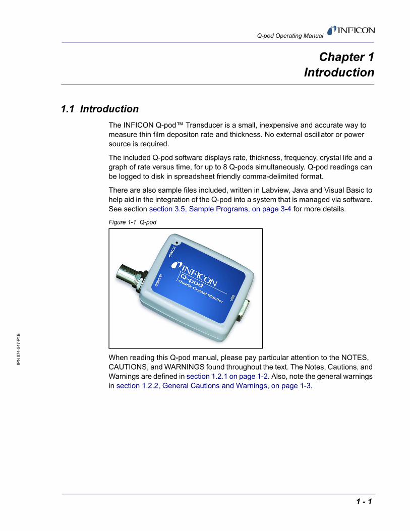
The INFICON Q-pod™ Transducer is a small, inexpensive and accurate way to measure thin film depositon rate and thickness. No external oscillator or power source is required.
The included Q-pod software displays rate, thickness, frequency, crystal life and a graph of rate versus time, for up to 8 Q-pods simultaneously. Q-pod readings can be logged to disk in spreadsheet friendly comma-delimited format.
There are also sample files included, written in Labview, Java and Visual Basic to help aid in the integration of the Q-pod into a system that is managed via software. See section section 3.5, Sample Programs, on page 3-4 for more details.
Figure 1-1 Q-pod
When reading this Q-pod manual, please pay particular attention to the NOTES, CAUTIONS, and WARNINGS found throughout the text. The Notes, Cautions, and Warnings are defined in section 1.2.1 on page 1-2. Also, note the general warnings in section 1.2.2, General Cautions and Warnings, on page 1-3.
1 - 1
IPN
07
4-54
7-P
1B
Q-pod Operating Manual
1.1.1 Related Manuals
Sensors are covered in separate manuals. PDF files of these manuals are contained in the 074-5000-G1 CD, part of the Ship Kit.
074-154 - Bakeable Sensor
074-156 - Front Load Sensor, Single/Dual
074-157 - Sputtering Sensor
147-800 - Cool Drawer Sensor, Single/Dual
1.2 Instrument Safety1.2.1 Definition of Notes, Cautions and Warnings
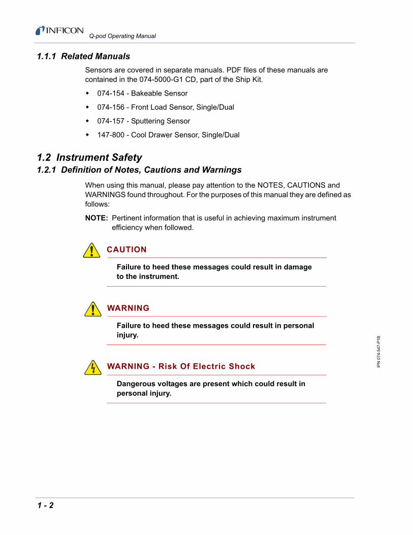
When using this manual, please pay attention to the NOTES, CAUTIONS and WARNINGS found throughout. For the purposes of this manual they are defined as follows:
NOTE: Pertinent information that is useful in achieving maximum instrument efficiency when followed.
CAUTION
Failure to heed these messages could result in damage to the instrument.
WARNING
Failure to heed these messages could result in personal injury.
WARNING - Risk Of Electric Shock
Dangerous voltages are present which could result in personal injury.
1 - 2

IPN
07
4-54
7-P
1B
Q-pod Operating Manual
1.2.2 General Cautions and Warnings
CAUTION
Do not open the instrument case! There are no user-serviceable components within the instrument case.
Refer all maintenance to technically qualified personnel.
WARNING
Failure to operate the Q-pod in the manner intended by INFICON can circumvent the safety protection provided by the instrument and may result in personal injury.
CAUTION
Q-pod may not be suitable for use with RF sputtering systems or other electrically noisy environments.
1 - 3

IPN
07
4-54
7-P
1B
Q-pod Operating Manual
1.3 How to Contact INFICON
Worldwide customer support information is available under Support at www.inficon.com where you can contact:
A Technical Support Engineer with questions regarding applications for and programming the Q-pod.
A Service Engineer with questions regarding troubleshooting, diagnosing or repairing a defective Q-pod.
Sales and Customer Service, to find the INFICON Sales office nearest to you.
Repair Service, to find the INFICON Service Center nearest to you.
If you are experiencing a problem with your Q-pod, please have the following information readily available:
The serial number and firmware version for your Q-pod.
A description of your problem.
An explanation of any corrective action that you may have already attempted.
The exact wording of any error messages that you may have received.
1.3.1 Returning Your Q-pod
Do not return any component of your Q-pod to INFICON without first speaking with a Customer Support Representative. You must obtain a Return Material Authorization (RMA) number from the Customer Support Representative.
If you deliver a package to INFICON without an RMA number, your package will be held and you will be contacted. This will result in delays in servicing your Q-pod.
1.4 Specifications
Frequency Range. . . . . . . . . . . . . . . 1 to 6 MHz
Frequency Resolution . . . . . . . . . . . 0.05 Hz at 6 MHz @ 2 measurements per second)
Frequency Accuracy . . . . . . . . . . . . 0.002%
Frequency Stability . . . . . . . . . . . . . . ±2 ppm total, over 0º to 50ºC
Thickness & Rate Resolution . . . . . . 0.0613 Å (new crystal); 0.1091 Å (crystal @ 4.5 MHz); over 500 ms sample for material density = 1.0, Z-ratio = 1.0
Input . . . . . . . . . . . . . . . . . . . . . . . . . BNC
Interface & Power. . . . . . . . . . . . . . . USB, v2.0 or later, 15 ft. (457 cm) maximum allowable length
Size . . . . . . . . . . . . . . . . . . . . . . . . . 1 in. x 2 in. x 2.5 in. (25 mmx 50 mm x 64 mm)
1 - 4

IPN
07
4-54
7-P
1B
Q-pod Operating Manual
Weight . . . . . . . . . . . . . . . . . . . . . . . 2 oz. (32 gm)
Computer Requirements . . . . . . . . . Any PC running Windows® XP / 2000 / Windows 7 32-bit with one available USB port for each Q-pod
1.5 Unpacking and Inspection
1 If the Q-pod has not been removed from its packaging, do so now.
2 Carefully examine the card for damage that may have occurred during shipping. This is especially important if you notice obvious rough handling on the outside of the container. Immediately report any damage to the carrier and to INFICON.
3 Do not discard the packing materials until you have taken inventory and have at least performed successful installation.
4 Take an inventory of your order by referring to your order invoice and the information contained in section 1.6.1.
5 To install the Q-pod, see Chapter 2, Quick Start.
6 For additional information or technical assistance, contact INFICON, refer to section 1.3 on page 1-4.
1.6 Parts and Options Overview1.6.1 Base Configuration
Q-pod Transducer w/Software . . . . . . . . .Q-POD
10 ft. USB Cable. . . . . . . . . . . . . . . . . . . .068-0472
6 in. BNC Cable . . . . . . . . . . . . . . . . . . . .755-257-G6
Technical Manual . . . . . . . . . . . . . . . . . . .074-547 on 074-5000-G1 CD
5.5 MHz Test Crystal . . . . . . . . . . . . . . . .782-902-023
1.6.2 Sensors
Front Load Single Sensor. . . . . . . . . . . . . . . . . . . . . SL-XXXXX
Cool Drawer Single Sensor . . . . . . . . . . . . . . . . . . . CDS-XXFXX
Sputtering Sensor. . . . . . . . . . . . . . . . . . . . . . . . . . . 750-618-G1
Front Load UHV Bakeable Sensor . . . . . . . . . . . . . . BK-AXF
NOTE: Multi-crystal (rotary) sensors & dual sensors should not be used with the Q-pod.
1 - 5

IPN
07
4-54
7-P
1B
Q-pod Operating Manual
This page is intentionally blank.
1 - 6

IPN
07
4-54
7-P
1B
Q-pod Operating Manual
Chapter 2Quick Start
2.1 Install Software
NOTE: If this is the initial Q-pod installation on this computer, you should install the Q-pod Software before connecting a Q-pod to the USB port.
1 Place the INFICON Program Disk in the computer’s CD-ROM.
2 Ignore the prompt and double-click the My Computer icon.
3 Right-click the CD-ROM icon, then click Open.
4 Double-click the Q-pod Transducer file.
5 Double click QPOD_V#_SETUP.EXE.
6 Follow the on screen directions and select the default installation options.
7 When software installation is complete, exit the installation program.
2.2 Connect the Q-pod
1 Connect the USB cable to a computer USB port, then to the Q-pod. See Figure 2-1.
1a If you are prompted to install the Q-pod drivers, select Install the Software Automatically.
1b If you are prompted concerning Windows Logo Testing, select Continue Anyway.
Figure 2-1 Q-pod Connections
2 - 1

IPN
07
4-54
7-P
1B
Q-pod Operating Manual
2 Use the 6 in. BNC cable provided to connect the Q-pod to the QCM sensor feedthrough.
3 The status light on the Q-pod illuminates when a quartz crystal is detected.
2.3 Using the Q-pod Software
Click the Q-pod desktop icon, or click Start >> Programs >> Sigma Instruments >> Q-pod. If you are prompted to assign Q-pod(s) to a channel, click Yes. Click Help to get more detailed information on materials and operation. Select Setup or Graph on the Main Screen menu to change the main screen display mode. See Figure 2-2.
Figure 2-2 Main Screen
2.3.1 Main Display
The top of the main screen is the main display. Here the Start button is used to start and record a run. Run time and run number are shown, along with the current time and date. The option to datalog during any given run is also given.
2.3.1.1 Reading Grid
The left grid displays the measured values of each connected Q-pod. Click Start to display Rate and Thickness readings. Frequency and Life readings are always displayed. Click a channel’s Zero button to zero the channel thickness reading. Shift-Click any channel Zero button to zero all thicknesses.
2 - 2

IPN
07
4-54
7-P
1B
Q-pod Operating Manual
2.3.1.2 Materials Grid
In the right grid, edit the Density, Z-Factor and Tooling values for the materials being deposited. Move your mouse over each setting to see a brief description.
2.3.2 Setup Display
The lower section of the main screen is where run parameters can be changed and Q-pod communication information is presented.
2.3.2.1 DataLog
Sets the file name, location and operation of disk data logging. Data log files can be set to overwrite the file name each time it is saved. It can append the data, by adding the newly recorded data to the end of the same file. It can also save each run in a new file designated by run number. Data is saved in comma delimited format for easy import into a spreadsheet.
2.3.2.2 Measurement
Sets the basic measurement parameters for all Q-pods. The values shown above are correct for most applications.
2.3.2.3 Display
Sets the display parameters.Thickness can be displayed in kÅ or Å. Mass can be displayed in ug/cm2. Rate will be changed to ng/cm2/sec if mass is the chosen option. Resolution of displayed readings may also be changed here (0.0 or 0.00). The rate reading filter can be set in this section. The Filter number represents how many measurements are averaged together to produce the displayed rate. The number of Q-pods being used is defined in this section as well.
2.3.2.4 Q-pods
Sets the name and displays the serial number of the Q-pod assigned to each measurement channel. A strike-through serial number indicates the Q-pod is not connected. The software can monitor a maximum of 8 Q-pods simultaneously.
2 - 3
IPN
07
4-54
7-P
1B
Q-pod Operating Manual
2.3.3 Graph Display
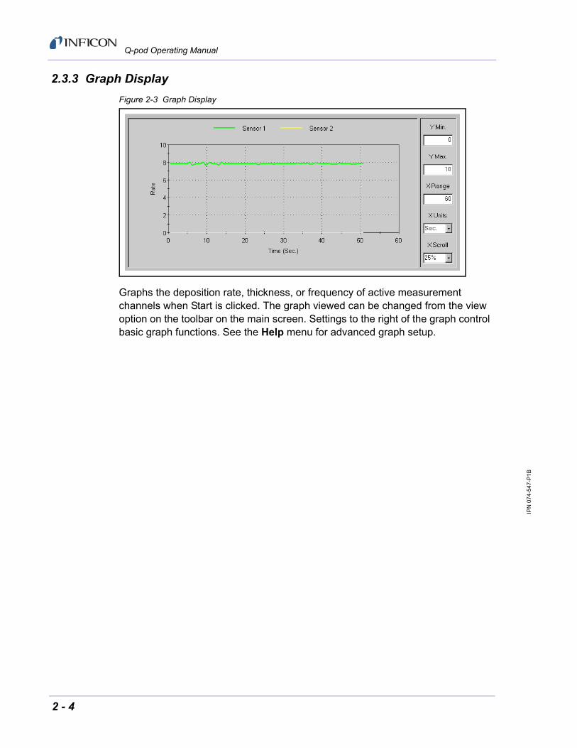
Figure 2-3 Graph Display
Graphs the deposition rate, thickness, or frequency of active measurement channels when Start is clicked. The graph viewed can be changed from the view option on the toolbar on the main screen. Settings to the right of the graph control basic graph functions. See the Help menu for advanced graph setup.
2 - 4

IPN
07
4-54
7-P
1B
Q-pod Operating Manual
Chapter 3Communications
3.1 Introduction
The Q-pod communicates via a USB (or USB2) port and a simple ASCII command set. An ActiveX DLL (Qpod.DLL) provides functions to set parameters, take readings, and handle USB communications.
3.2 ASCII Command Set
The commands below assume you can open the proper USB port for communications. The section on Qpod.DLL provides the tools needed to communicate with the Q-pod without knowledge of USB functions.
A Q-pod command consists of an exclamation character (&H21), then the command as detailed below, and terminated with a Carriage Return (&H13) and Line Feed (&H10). The response has the same format, that is !<response>CrLf.
@ Get version
Returns: Qpod VX.XX
A# Get Frequency and Set Status LED
Returns frequency counts. The B & C commands (see below) must be used to set the measurement period before using this command. The response is gate counts, which are converted crystal frequency using:
Freq = 200 MHz * GatePeriod / Response
A response of –1 indicates that a new reading is not available.
The value sent with this command activates the Status LED. Send A1 to turn on the LED (crystal good), or A0 to cause the LED to flash at the measurement rate (crystal fail).
B# Set Gate Period
Sets the longest measurement period, determined by the lowest valid crystal frequency. If the desired measurement period is 0.25 seconds, and the minimum crystal frequency is 5.0MHz, then the command is: B1250000 (0.25 x 5MHz).
C# Set Measurement Period
The value sent is the period in seconds times the reference oscillator frequency, 50MHz. If the desired measurement period is 0.25 seconds, then the command is: C12500000 (0.25 x 50MHz)
3 - 1
IPN
07
4-54
7-P
1B
Q-pod Operating Manual
3.3 QPOD.DLL
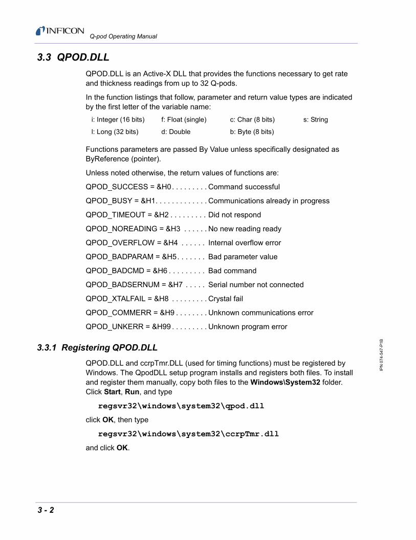
QPOD.DLL is an Active-X DLL that provides the functions necessary to get rate and thickness readings from up to 32 Q-pods.
In the function listings that follow, parameter and return value types are indicated by the first letter of the variable name:
Functions parameters are passed By Value unless specifically designated as ByReference (pointer).
Unless noted otherwise, the return values of functions are:
QPOD_SUCCESS = &H0. . . . . . . . . Command successful
QPOD_BUSY = &H1. . . . . . . . . . . . . Communications already in progress
QPOD_TIMEOUT = &H2 . . . . . . . . . Did not respond
QPOD_NOREADING = &H3 . . . . . . No new reading ready
QPOD_OVERFLOW = &H4 . . . . . . Internal overflow error
QPOD_BADPARAM = &H5. . . . . . . Bad parameter value
QPOD_BADCMD = &H6 . . . . . . . . . Bad command
QPOD_BADSERNUM = &H7 . . . . . Serial number not connected
QPOD_XTALFAIL = &H8 . . . . . . . . . Crystal fail
QPOD_COMMERR = &H9 . . . . . . . . Unknown communications error
QPOD_UNKERR = &H99 . . . . . . . . . Unknown program error
3.3.1 Registering QPOD.DLL
QPOD.DLL and ccrpTmr.DLL (used for timing functions) must be registered by Windows. The QpodDLL setup program installs and registers both files. To install and register them manually, copy both files to the Windows\System32 folder. Click Start, Run, and type
regsvr32\windows\system32\qpod.dll
click OK, then type
regsvr32\windows\system32\ccrpTmr.dll
and click OK.
i: Integer (16 bits) f: Float (single) c: Char (8 bits) s: String
l: Long (32 bits) d: Double b: Byte (8 bits)
3 - 2
IPN
07
4-54
7-P
1B
Q-pod Operating Manual
3.3.2 Functions
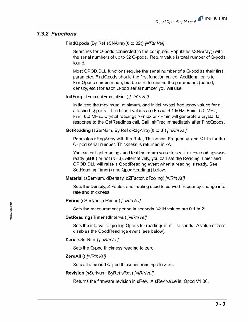
FindQpods (By Ref sSNArray(0 to 32)) [=lRtnVal]
Searches for Q-pods connected to the computer. Populates sSNArray() with the serial numbers of up to 32 Q-pods. Return value is total number of Q-pods found.
Most QPOD.DLL functions require the serial number of a Q-pod as their first parameter. FindQpods should the first function called. Additional calls to FindQpods can be made, but be sure to resend the parameters (period, density, etc.) for each Q-pod serial number you will use.
InitFreq (dFmax, dFmin, dFinit) [=lRtnVal]
Initializes the maximum, minimum, and initial crystal frequency values for all attached Q-pods. The default values are Fmax=6.1 MHz, Fmin=5.0 MHz, Finit=6.0 MHz,. Crystal readings >Fmax or <Fmin will generate a crystal fail response to the GetReadings call. Call InitFreq immediately after FindQpods.
GetReading (sSerNum, By Ref dRdgArray(0 to 3)) [=lRtnVal]
Populates dRdgArray with the Rate, Thickness, Frequency, and %Life for the Q- pod serial number. Thickness is returned in kA.
You can call get readings and test the return value to see if a new readings was ready (&H0) or not (&H3). Alternatively, you can set the Reading Timer and QPOD.DLL will raise a QpodReading event when a reading is ready. See SetReading Timer() and QpodReading() below.
Material (sSerNum, dDensity, dZFactor, dTooling) [=lRtnVal]
Sets the Density, Z Factor, and Tooling used to convert frequency change into rate and thickness.
Period (sSerNum, dPeriod) [=lRtnVal]
Sets the measurement period in seconds. Valid values are 0.1 to 2.
SetReadingsTimer (dInterval) [=lRtnVal]
Sets the interval for polling Qpods for readings in milliseconds. A value of zero disables the QpodReadings event (see below).
Zero (sSerNum) [=lRtnVal]
Sets the Q-pod thickness reading to zero.
ZeroAll () [=lRtnVal]
Sets all attached Q-pod thickness readings to zero.
Revision (sSerNum, ByRef sRev) [=lRtnVal]
Returns the firmware revision in sRev. A sRev value is: Qpod V1.00.
3 - 3
IPN
07
4-54
7-P
1B
Q-pod Operating Manual
3.3.3 Events
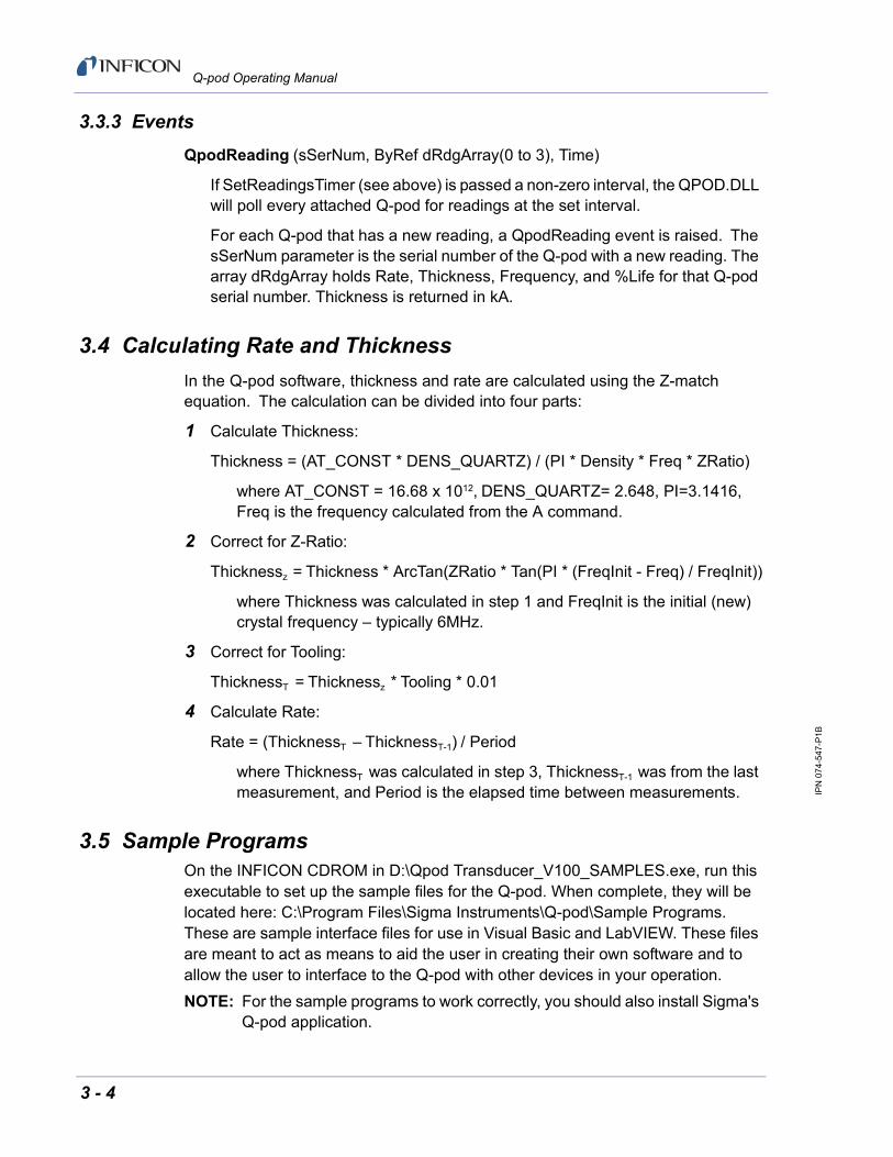
QpodReading (sSerNum, ByRef dRdgArray(0 to 3), Time)
If SetReadingsTimer (see above) is passed a non-zero interval, the QPOD.DLL will poll every attached Q-pod for readings at the set interval.
For each Q-pod that has a new reading, a QpodReading event is raised. The sSerNum parameter is the serial number of the Q-pod with a new reading. The array dRdgArray holds Rate, Thickness, Frequency, and %Life for that Q-pod serial number. Thickness is returned in kA.
3.4 Calculating Rate and Thickness
In the Q-pod software, thickness and rate are calculated using the Z-match equation. The calculation can be divided into four parts:
1 Calculate Thickness:
Thickness = (AT_CONST * DENS_QUARTZ) / (PI * Density * Freq * ZRatio)
where AT_CONST = 16.68 x 10¹², DENS_QUARTZ= 2.648, PI=3.1416, Freq is the frequency calculated from the A command.
2 Correct for Z-Ratio:
Thicknessz = Thickness * ArcTan(ZRatio * Tan(PI * (FreqInit - Freq) / FreqInit))
where Thickness was calculated in step 1 and FreqInit is the initial (new) crystal frequency – typically 6MHz.
3 Correct for Tooling:
ThicknessT = Thicknessz * Tooling * 0.01
4 Calculate Rate:
Rate = (ThicknessT – ThicknessT-1) / Period
where ThicknessT was calculated in step 3, ThicknessT-1 was from the last measurement, and Period is the elapsed time between measurements.
3.5 Sample ProgramsOn the INFICON CDROM in D:\Qpod Transducer_V100_SAMPLES.exe, run this executable to set up the sample files for the Q-pod. When complete, they will be located here: C:\Program Files\Sigma Instruments\Q-pod\Sample Programs. These are sample interface files for use in Visual Basic and LabVIEW. These files are meant to act as means to aid the user in creating their own software and to allow the user to interface to the Q-pod with other devices in your operation.
NOTE: For the sample programs to work correctly, you should also install Sigma's Q-pod application.
3 - 4

IPN
07
4-54
7-P
1B
Q-pod Operating Manual
Before using the LabVIEW demo, it may be best to familiarize oneself with operation of the Q-pod software. To run the LabVIEW demo(qpod.vi), click "Load DLL", "Use Card" and then set the Sensor parameters as desired. Click "Start" to display readings. Be sure to click "Unload DLL" before stopping the LabVIEW program. Otherwise, a Windows error may occur, and LabVIEW may shut down. LabVIEW 6 or higher is required.
NOTE: The sample LabView VI may require that you select the proper DLL for the two Automation RefNum controls. Right click each control, then click Select ActiveX Class. Check Show Creatable Objects Only, then select Sigma Instruments Qpod ActiveX DLL.
Figure 3-1 Labview Sample Program
3 - 5

IPN
07
4-54
7-P
1B
Q-pod Operating Manual
This page is intentionally blank.
3 - 6

IPN
07
4-54
7-P
1B
Q-pod Operating Manual
Chapter 4Troubleshooting and Maintenance
4.1 Troubleshooting Guide
If the Q-pod fails to function, or appears to have diminished performance, the following Symptom/Cause/Remedy charts may be helpful.
CAUTION
There are no user serviceable components within the Q-pod case.
Refer all maintenance to qualified personnel.
4.1.1 Status LED
If there is a problem with the Q-pod, the status LED will indicate as to the likely cause.
4.1.1.1 LED illuminated steady
Good crystal detected
4.1.1.2 LED flashes slowly (about 2 Hz)
No crystal connected
Crystal frequency range not set correctly in software
Crystal failure
4.1.1.3 LED flashes rapidly (about 10 Hz)
Software not installed
Driver not installed
Q-pod not detected by software
Q-pod not assigned to a sensor channel (click Find to locate Q-Pod and then follow instructions to assign Q-Pod to a sensor channel)
Q-pod hardware failure
4 - 1
IPN
07
4-54
7-P
1B
Q-pod Operating Manual
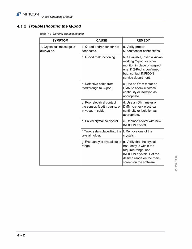
4.1.2 Troubleshooting the Q-pod
Table 4-1 General Troubleshooting
SYMPTOM CAUSE REMEDY
1. Crystal fail message is always on.
a. Q-pod and/or sensor not connected.
a. Verify proper Q-pod/sensor connections.
b. Q-pod malfunctioning. b. If available, insert a known working Q-pod, or other monitor, in place of suspect one; if Q-Pod is confirmed bad, contact INFICON service department.
c. Defective cable from feedthrough to Q-pod.
c. Use an Ohm meter or DMM to check electrical continuity or isolation as appropriate.
d. Poor electrical contact in the sensor, feedthroughs, or in-vacuum cable.
d. Use an Ohm meter or DMM to check electrical continuity or isolation as appropriate.
e. Failed crystal/no crystal. e. Replace crystal with new INFICON crystal.
f. Two crystals placed into the crystal holder.
f. Remove one of the crystals.
g. Frequency of crystal out of range,
g. Verify that the crystal frequency is within the required range, use INFICON crystals. Set the desired range on the main screen on the software.
4 - 2
IPN
07
4-54
7-P
1B
Q-pod Operating Manual
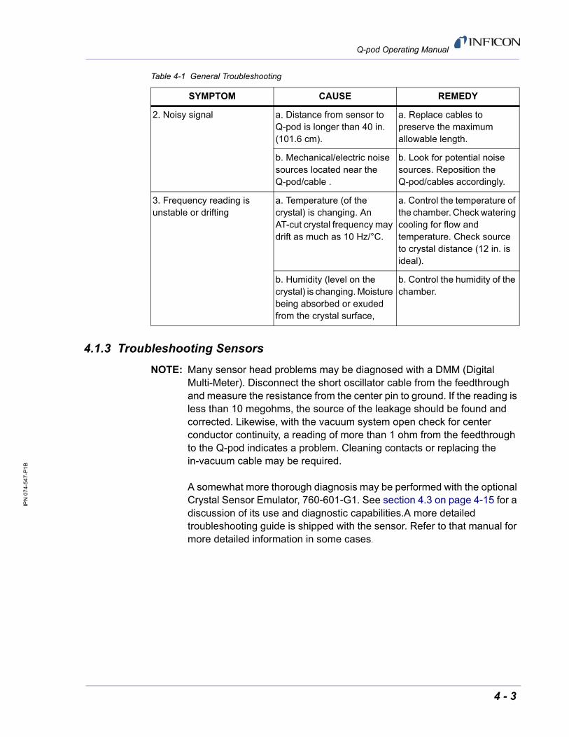
4.1.3 Troubleshooting Sensors
NOTE: Many sensor head problems may be diagnosed with a DMM (Digital Multi-Meter). Disconnect the short oscillator cable from the feedthrough and measure the resistance from the center pin to ground. If the reading is less than 10 megohms, the source of the leakage should be found and corrected. Likewise, with the vacuum system open check for center conductor continuity, a reading of more than 1 ohm from the feedthrough to the Q-pod indicates a problem. Cleaning contacts or replacing the in-vacuum cable may be required.
A somewhat more thorough diagnosis may be performed with the optional Crystal Sensor Emulator, 760-601-G1. See section 4.3 on page 4-15 for a discussion of its use and diagnostic capabilities.A more detailed troubleshooting guide is shipped with the sensor. Refer to that manual for more detailed information in some cases.
2. Noisy signal a. Distance from sensor to Q-pod is longer than 40 in. (101.6 cm).
a. Replace cables to preserve the maximum allowable length.
b. Mechanical/electric noise sources located near the Q-pod/cable .
b. Look for potential noise sources. Reposition the Q-pod/cables accordingly.
3. Frequency reading is unstable or drifting
a. Temperature (of the crystal) is changing. An AT-cut crystal frequency may drift as much as 10 Hz/°C.
a. Control the temperature of the chamber. Check watering cooling for flow and temperature. Check source to crystal distance (12 in. is ideal).
b. Humidity (level on the crystal) is changing. Moisture being absorbed or exuded from the crystal surface,
b. Control the humidity of the chamber.
Table 4-1 General Troubleshooting
SYMPTOM CAUSE REMEDY
4 - 3

IPN
07
4-54
7-P
1B
Q-pod Operating Manual
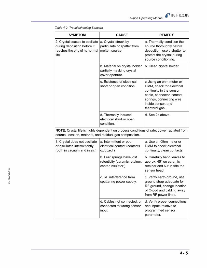
Table 4-2 Troubleshooting Sensors
SYMPTOM CAUSE REMEDY
1. Large jumps of thickness reading during deposition.
a. Mode hopping. a. Mode hopping is a byproduct of active oscillation with a heavily damped crystal. Temperature stabilization is key in diminishing this. Replace the crystal.
b. Stress causes film to peel from crystal surface.
b. Replace crystal or use high performance RunSaver™ crystal; consult factory.
c. Particulate or "spatter" from molten source striking crystal.
c. Thermally condition the source thoroughly before deposition, use a shutter to protect the crystal during source conditioning.
d. Material build up, scratches or foreign particles on the crystal holder seating surface (improper crystal seating.)
d. Clean and polish the crystal seating surface on the crystal holder.
e. Small pieces of material fell on crystal (for crystal facing up sputtering situation.)
e. Check the crystal surface and blow it off with clean air.
f. Small pieces of magnetic material being attracted by the sensor magnet and contacting the crystal (sputtering sensor head.)
f. Check the sensor cover's aperture and remove any foreign material that may be restricting full crystal coverage.
4 - 4
IPN
07
4-54
7-P
1B
Q-pod Operating Manual
2. Crystal ceases to oscillate during deposition before it reaches the end of its normal life.
a. Crystal struck by particulate or spatter from molten source.
a. Thermally condition the source thoroughly before deposition, use a shutter to protect the crystal during source conditioning.
b. Material on crystal holder partially masking crystal cover aperture.
b. Clean crystal holder.
c. Existence of electrical short or open condition.
c.Using an ohm meter or DMM, check for electrical continuity in the sensor cable, connector, contact springs, connecting wire inside sensor, and feedthroughs.
d. Thermally induced electrical short or open condition.
d. See 2c above.
NOTE: Crystal life is highly dependent on process conditions of rate, power radiated from source, location, material, and residual gas composition.
3. Crystal does not oscillate or oscillates intermittently (both in vacuum and in air.)
a. Intermittent or poor electrical contact (contacts oxidized.)
a. Use an Ohm meter or DMM to check electrical continuity, clean contacts.
b. Leaf springs have lost retentivity (ceramic retainer, center insulator.)
b. Carefully bend leaves to approx. 45° on ceramic retainer and 60° inside the sensor head.
c. RF interference from sputtering power supply.
c. Verify earth ground, use ground strap adequate for RF ground, change location of Q-pod and cabling away from RF power lines.
d. Cables not connected, or connected to wrong sensor input.
d. Verify proper connections, and inputs relative to programmed sensor parameter.
Table 4-2 Troubleshooting Sensors
SYMPTOM CAUSE REMEDY
4 - 5

IPN
07
4-54
7-P
1B
Q-pod Operating Manual
4. Crystal oscillates in vacuum but stops oscillation after open to air.
a. Crystal was near the end of its life; opening to air causes film oxidation which increases film stress.
a. Replace crystal.
b. Excessive moisture accumulates on the crystal.
b. Turn off cooling water to sensor prior to venting, flow warm water through sensor while chamber is open.
5. Thermal instability: large changes in thickness reading during source warm-up (usually causes thickness reading to decrease) and after the termination of deposition (usually causes thickness reading to increase.)
a. Inadequate cooling water/cooling water temperature too high.
a. Check cooling water flow rate, be certain that cooling water temperature is less than 30°C; refer to appropriate sensor manual.
b. Excessive heat input to the crystal.
b. If heat is due to radiation from the evaporation source, move sensor further away from source and use silver crystals for better thermal stability; install radiation shield.
c. Crystal not seated properly in holder.
c. Clean or polish the crystal seating surface on the crystal holder.
d. Crystal heating caused by high energy electron flux (often found in RF sputtering.)
d. Use a sputtering sensor head.
e. Poor thermal transfer (Bakeable.)
f. Use Al or Au foil washer between crystal holder and sensor body.
Table 4-2 Troubleshooting Sensors
SYMPTOM CAUSE REMEDY
4 - 6

IPN
07
4-54
7-P
1B
Q-pod Operating Manual
6. Poor thickness reproducibility.
a. Variable source flux distribution.
a. Move sensor to a more central location to reliably sample evaporant, ensure constant relative pool height of melt, avoid tunneling into the melt.
b. Sweep, dither, or position where the electron beam strikes the melt has been changed since the last deposition.
b. Maintain consistent source distribution by maintaining consistent sweep frequencies, sweep amplitude and electron beam position settings.
c. Material does not adhere to the crystal.
c. Make certain the crystal surface is clean; avoid touching crystal with fingers, make use of an intermediate adhesion layer.
d. Cyclic change in rate. d. Make certain source's sweep frequency is not "beating" with the Q-pod’s measurement frequency.
7. Large drift in thickness (greater than 200 Å for a density of 5.00 g/cc) after termination of sputtering.
a. Crystal heating due to poor thermal contact.
a. Clean or polish the crystal seating surface on the crystal holder.
b. External magnetic field interfering with the sensor's magnetic field (sputtering sensor.)
b. Rotate sensor magnet to proper orientation with external magnetic field, refer to the sputtering sensor manual IPN 074-157.
c. Sensor magnet cracked or demagnetized (sputtering sensor.)
c. Check sensor magnetic field strength, the maximum field at the center of the aperture should be 700 gauss or greater.
Table 4-2 Troubleshooting Sensors
SYMPTOM CAUSE REMEDY
4 - 7

IPN
07
4-54
7-P
1B
Q-pod Operating Manual
4.1.4 Troubleshooting Computer Communications
4.2 Replacing the Crystal
CAUTION
Always use clean nylon lab gloves and plastic tweezers for handling the crystal (to avoid contamination which may lead to poor adhesion of the film to the electrode).
Do not rotate the ceramic retainer assembly after it is seated (as this will scratch the crystal electrode and cause poor contact).
Do not use excessive force when handling the ceramic retainer assembly since breakage may occur.
NOTE: Certain materials, especially dielectrics, may not adhere strongly to the crystal surface and may cause erratic readings.
NOTE: Thick deposits of some materials, such as SiO, Si, and Ni will normally peel off the crystal when it is exposed to air, as a result of changes in film stress caused by gas absorption. When you observe peeling, replace the crystals.
Table 4-3 Troubleshooting Computer Communications
SYMPTOM CAUSE REMEDY
1. Communications cannot be established between the host computer and the Q-pod.
a. Improper cable connection.
a. Verify for cable connections are seated properly.
b. Driver not installed properly.
b. Reinstall drivers. Confirm the operating sytem is an accepted OS. If autorun driver install feature does not work, the driver can be installed from the device manager manually.
4 - 8

IPN
07
4-54
7-P
1B
Q-pod Operating Manual
4.2.1 Front Load
Follow the procedure below to replace the crystal in the Front Load sensor: (see Figure 4-1)
1 Gripping the crystal holder with your fingers, pull it straight out of the sensor body.
2 Gently pry the crystal retainer from the holder (or use the Crystal Snatcher; see Figure 4-6 on page 4-14).
3 Turn the retainer over and the crystal will drop out.
4 Install a new crystal, with the patterned electrode face up.
5 Push the retainer back into the holder and replace the holder in the sensor body.
Figure 4-1 Front Load Crystal Sensor (Exploded)
Front Load Crystal Holder(IPN 750-172-G1)
Front Load StandardCrystal Sensor Body(IPN 750-207-G1)
Crystal (IPN 008-010-G10)Fully Coated Face (Gold)
Finger Spring Contact(IPN 750-171-P1)
Crystal Retainer(IPN 007-023)
In-Vacuum CableTo XIU
Water Tubes
4 - 9

IPN
07
4-54
7-P
1B
Q-pod Operating Manual
4.2.2 Cool Drawer
Follow the procedure below to replace the crystal in a Next Generation Cool Drawer™ sensor:
1 Using your thumb and index fingers, gently squeeze the sides of the retainer at the mid section then lift it up, away from the drawer, as shown in Figure 4-2.
2 Hold the drawer by the handle and turn it upside down to remove the spent crystal.
3 Install a new crystal in the drawer. Observe its orientation. The pattern electrode should face upward as shown in Figure 4-3.
4 Hold the retainer by its sides. Align its orientation notch with the drawer then gently and evenly push the retainer down until it snaps firmly into the drawer. see Figure 4-3. Never push down (or pull up) on the contact spring, doing so may permanently damage it.
5 Inspect the whole assembly. The retainer should be even and engage the drawer at all four corners.
Figure 4-2 Cool Drawer - Removing The Crystal
Contact Spring
4 - 10

IPN
07
4-54
7-P
1B
Q-pod Operating Manual
Figure 4-3 Cool Drawer - Replacing The Crystal
OrientationNotch
Handle
Retainer
Crystal
Drawer
4 - 11
IPN
07
4-54
7-P
1B
Q-pod Operating Manual
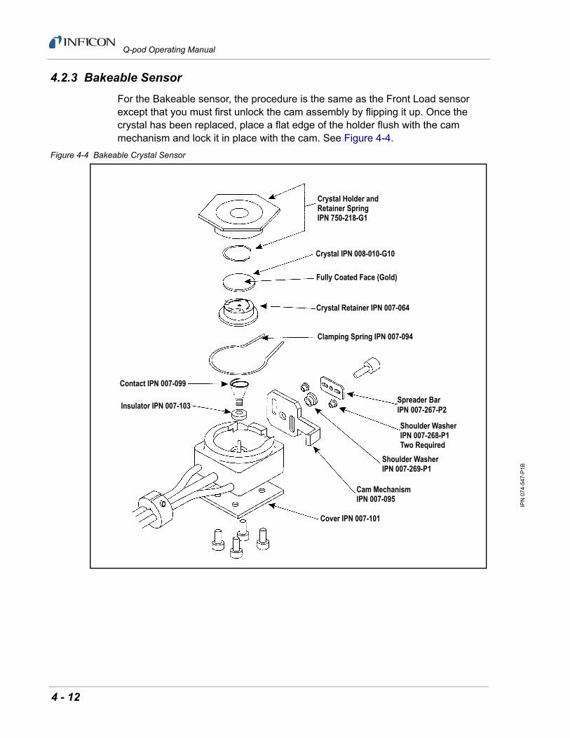
4.2.3 Bakeable Sensor
For the Bakeable sensor, the procedure is the same as the Front Load sensor except that you must first unlock the cam assembly by flipping it up. Once the crystal has been replaced, place a flat edge of the holder flush with the cam mechanism and lock it in place with the cam. See Figure 4-4.
Figure 4-4 Bakeable Crystal Sensor
Crystal Holder andRetainer SpringIPN 750-218-G1
Crystal IPN 008-010-G10
Fully Coated Face (Gold)
Crystal Retainer IPN 007-064
Clamping Spring IPN 007-094
Contact IPN 007-099
Insulator IPN 007-103Spreader BarIPN 007-267-P2
Shoulder WasherIPN 007-268-P1Two Required
Shoulder WasherIPN 007-269-P1
Cam MechanismIPN 007-095
Cover IPN 007-101
4 - 12

IPN
07
4-54
7-P
1B
Q-pod Operating Manual
4.2.4 Sputtering Sensor
Observe the general precautions for replacing crystals and follow the instructions below to replace the crystal in a sputtering sensor.
1 Grip the body assembly with your fingers and pull it straight out to separate it from the water-cooled front cover. (You may have to disconnect the sensor cable in order to separate the parts.) See Figure 4-5.
2 Pull the crystal holder straight out from the front of the body assembly.
3 Remove the ceramic retainer from the crystal holder by pulling it straight out with the crystal snatcher (see section 4.2.5 on page 4-14).
4 Turn the crystal holder over so that the crystal drops out.
5 Install a new crystal into the crystal holder with the patterned electrode facing the back and contacting the leaf springs on the ceramic retainer.
6 Put the ceramic retainer back into the crystal holder and put the holder into the body assembly of the sensor.
7 Align the position of the body assembly so that the connector matches with the notch on the front cover of the sensor. Snap the two parts together. Reconnect the sensor cable if it has been disconnected.
Figure 4-5 Sputtering Crystal Sensor
Body AssemblyIPN 750-619-G1
In-Vacuum Cable Assembly(29 in.) IPN 007-044
Ceramic RetainerIPN 007-023
CrystalIPN 008-009-G10
(Silver)
Crystal HolderIPN 007-049
SensorFront CoverIPN 007-047
4 - 13

IPN
07
4-54
7-P
1B
Q-pod Operating Manual
4.2.5 Crystal Snatcher
Use the crystal snatcher, supplied with the sensor, as follows:
1 Insert crystal snatcher into ceramic retainer (1) and apply a small amount of pressure. This locks the retainer to the snatcher and allows the retainer to be pulled straight out (2). See Figure 4-6.
2 Reinsert the retainer into the holder after the crystal has been replaced.
3 Release the crystal snatcher with a slight side-to-side motion.
Figure 4-6 Use of the Crystal Snatcher
4 - 14

IPN
07
4-54
7-P
1B
Q-pod Operating Manual
4.3 Crystal Sensor EmulatorIPN 760-601-G2
NOTE: 760-601-G2 is fully compatible with all Thin Film Deposition Controllers.
The Crystal Sensor Emulator option is used in conjunction with the Thin Film Deposition Controller to rapidly diagnose problems with the Deposition Controller's measurement system. See Figure 4-7.
Figure 4-7 Crystal Sensor Emulator
The Crystal Sensor Emulator may be attached at various points in the measurement system, from the oscillator to the sensor head. It provides a known good monitor crystal with known good electrical connections. Using the emulator and the controller in a systematic manner provides a fast means of isolating measurement system, cable, or sensor problems. See Figure 4-8.
Figure 4-8 Crystal Sensor Emulator Attachment Points
CAUTION
This product is designed as a diagnostic tool, and is not intended for use in vacuum. Do not leave the Crystal Sensor Emulator installed in the vacuum system during processing.
FemaleBNC
Connector
FemaleMicrodot
Connector
SensorCover
Connector
Thin FilmController
Crystal InterfaceUnit (Oscillator)
Sensor Head
A
B
C
4 - 15
IPN
07
4-54
7-P
1B
Q-pod Operating Manual
4.3.1 Diagnostic Procedures
The following diagnostic procedures employ the Crystal Sensor Emulator to analyze a constant Crystal Fail message. The symptom is a Crystal Fail message that is displayed by the Q-pod software even after the monitor crystal has been replaced with a new good monitor crystal.
4.3.1.1 Measurement System Diagnostic Procedure
1 Refer to Figure 4-8 on page 4-15. Remove the six-inch BNC cable from the Feed-Through at point A.
2 Connect the Crystal Sensor Emulator to the 6 inch BNC cable at Point A.
If the Crystal Fail message disappears after approximately five seconds, the measurement system is working properly. Re-install the six-inch BNC cable to the Feed-Through. Go to section 4.3.1.2.
If the Crystal Fail message remains, continue at step 3.
3 Disconnect the six-inch BNC cable from the Oscillator and from the Emulator.
4 Visually inspect the six-inch BNC cable to verify that the center pins are seated properly.
5 Use an Ohm meter to verify the electrical connections on the six-inch BNC cable.
There must be continuity (<0.2 ohms, after accounting for resistance of ohmeter leads) between the center pins.
There must be isolation (>10 megohms) between the center pins and the connector shield.
There must be continuity between the connector shields.
Replace the six-inch BNC cable if it is found to be defective and repeat Step 2 of this procedure.
6 If the six-inch BNC cable is not defective, re-connect the six-inch cable to the oscillator and to the Crystal Sensor Emulator. If the Crystal Fail message remains, contact INFICON.
4 - 16

IPN
07
4-54
7-P
1B
Q-pod Operating Manual
4.3.1.2 Feed-Through Or In-Vacuum Cable Diagnostic Procedure
1 Refer to Figure 4-8 on page 4-15. Remove the In-Vacuum cable from the Sensor Head at point B.
2 Connect the Crystal Sensor Emulator to the In-Vacuum cable.
If the Crystal Fail message disappears after approximately five seconds, the Feed-Through and In-Vacuum Cable are working properly. Re-install the In-Vacuum cable to the Sensor Head. Go to section section 4.3.1.3 on page 4-18.
If the Crystal Fail message remains, continue at step 3.
3 Disconnect the In-Vacuum cable from the Feed-Through and the Emulator. Disconnect the six-inch BNC cable from the Feed-Through.
4 Using an Ohm Meter, verify electrical continuity from the BNC center pin on the Feed-Through to the Microdot center pin on the Feed-Through. A typical value would be less than 0.2 ohms.
5 Verify electrical isolation of the center pin on the Feed-Through from the electrical ground (Feed-Through body). A typical value would be in excess of 10 megohms.
If the Feed-Through is found to be defective, replace the Feed-Through, re-attach the BNC and In-Vacuum cables, and repeat this procedure starting at Step 2, otherwise continue at step 6.
6 Verify electrical continuity from center pin to center pin on the In-Vacuum cable.
7 Verify that the center pin of the In-Vacuum cable is electrically isolated from the In-Vacuum cable shield.
If the In-Vacuum cable is found to be defective, replace the In-Vacuum cable. Re-attach the BNC and In-Vacuum cables, and repeat this procedure starting at Step 2, otherwise continue at step 8.
8 Connect the In-Vacuum Cable to the Feed-Through.
9 Verify electrical continuity from the center pin on the BNC connector of the Feed-Through to the center pin on the un-terminated end of the In-Vacuum cable.
10 Verify electrical isolation from the center pin to electrical ground (Feed-Through body).
If the Feed-Through/In-Vacuum cable system is found to be defective, look for defective electrical contacts at the Feed-Through to In-Vacuum cable connection. Repair or replace the Feed-Through as necessary. Re-attach the BNC and In-Vacuum cables and repeat this procedure starting at step 2. Otherwise, continue at step 11.
4 - 17
IPN
07
4-54
7-P
1B
Q-pod Operating Manual
11 Connect the six-inch BNC cable to the Feed-Through and disconnect it from the Q-pod.
12 Verify electrical continuity from the center pin of the Microdot connector on the Feed-Through to the un-terminated end of the six-inch BNC cable.
13 Verify electrical isolation from the center pin to electrical ground (Feed-Through body).
If the Feed-Through/six-inch BNC cable system is found to be defective, look for defective contacts at the Feed-Through to BNC cable connection. Repair or replace the Feed-Through as necessary, re-attach the BNC cable to the XIU and In-Vacuum cable to the Crystal head and repeat this procedure starting at step 2.
4.3.1.3 Sensor Head Or Monitor Crystal Diagnostic Procedure
NOTE: The procedure is for use with front load style sensor heads.
1 Remove the Crystal Cover from the Sensor Head.
2 Refer to Figure 4-7 on page 4-15. Connect the Crystal Sensor Emulator to the Sensor Head at Point C.
If the Crystal Fail message disappears after approximately 5 seconds the Sensor Head is operating properly. Remove the Crystal Sensor Emulator and re-insert the Crystal Cover into the Sensor Head.
If the Crystal Fail message remains, continue at step 3.
3 Disconnect the In-Vacuum cable from the Sensor Head and the Feed-Through. Remove the Crystal Sensor Emulator from the Sensor Head.
4 Using an Ohm meter, verify the electrical connections on the Sensor Head.
Verify there is electrical continuity from the center pin contact on the Microdot connector on the Sensor Head to the leaf spring contact in the Sensor Head. Take care not to apply to much pressure on the center pin of the microdot connector as it may become damaged.
There must be electrical isolation between the center pin of the Microdot connector and the Sensor Head body.
If the Sensor Head is found to be defective, contact INFICON to have the Sensor Head repaired.
4 - 18
IPN
07
4-54
7-P
1B
Q-pod Operating Manual
5 Connect the In-Vacuum Cable to the Sensor Head.
Verify there is continuity (<0.2 ohm) from the leaf spring contact in the Sensor Head to the center pin on the un-terminated end of the In-Vacuum cable.
Verify there is isolation (>10 megohm) between the leaf spring contact and the In-Vacuum cable shield.
If the Sensor Head or the In-Vacuum cable system is found to be defective, look for defective contacts at the In-Vacuum cable to Sensor Head connection, repair or replace the Sensor Head as necessary. Re-attach the In-Vacuum cable to the Feed-Through and repeat this procedure starting at step 2.
6 Ensure that the leaf springs in the Sensor Head and those in the Ceramic Retainer are bent to an angle of approximately 60º and 45º from flat, respectively.
4.3.1.4 System Diagnostics Pass But Crystal Fail Message Remains
If the system is operating properly yet the Crystal Fail message is still displayed, perform the following tasks.
1 On the Ceramic Retainer verify that the center rivet is secure. Repair or replace the Ceramic Retainer as necessary.
2 Inspect the inside of the Crystal Holder for build-up of material. Clean or replace the Crystal Holder as necessary.
After verifying the Sensor Head contacts, the Sensor Head/In-Vacuum cable connection and the ceramic retainer contacts, re-assemble the system. If the Crystal Fail message remains, replace the monitor crystal with a new monitor crystal. Verify that the monitor crystal works properly by inserting it into a known good measurement system. If you continue to experience problems, contact INFICON.
4 - 19

IPN
07
4-54
7-P
1B
Q-pod Operating Manual
4.3.2 Sensor Cover Connection
The Crystal Sensor Emulator can be used to verify the measurement system for INFICON Thin Film Deposition Controllers and Monitors.
However, the Crystal Sensor Emulator's Sensor Cover Connector is compatible with some sensor heads, and is incompatible with others. This is discussed in the following sections.
4.3.2.1 Compatible Sensor Heads
The Sensor Cover Connection will fit the sensor heads shown in Table 4-4.
4.3.2.2 Incompatible Sensor Heads
The Sensor Heads for which the Crystal Sensor Emulator's Sensor Cover Connector will not fit are shown in Table 4-5.
NOTE: The Crystal Sensor Emulator’s Sensor Cover will not fit the crystal holder opening of the older style INFICON transducers that have the soldered finger springs.
Table 4-4 Compatible Sensor Heads
Sensor Head Part Number
Front Load Single Sensor Head SL-XXXXX
Front Load Dual Sensor Head DL-AEXX
Table 4-5 Incompatible Sensor Heads
Sensor Head Part Number
Front Load UHV Bakeable Sensor Head BK-AXX
Cool Drawer Single Sensor Head CDS-XXXXX
Sputtering Sensor Head 750-618-G1
CrystalSix Sensor Head 750-446-G1
Cool Drawer Dual Sensor Head CDD-XXXX
Crystal12 Sensor Head XL12-XXXXXX
RSH-600 Sensor Head 15320X-XX
4 - 20

IPN
07
4-54
7-P
1B
Q-pod Operating Manual
4.3.3 Emulator Specifications
Dimensions
1.58 in. diameter x 1.79 in.(40.13 mm diameter x 45.47 mm)
Temperature Range
0 to 50oC
Frequency
760-601-G2: 5.5 MHz ± 1 ppm at room temperature
Materials
304 Stainless Steel, Nylon, Teflon®, brass. Some internal components contain zinc, tin, and lead.
4 - 21

IPN
07
4-54
7-P
1B
Q-pod Operating Manual
This page is intentionally blank.
4 - 22

IPN
07
4-54
7-P
1B
Q-pod Operating Manual
Chapter 5Calibration Procedures
5.1 Importance of Density, Tooling and Z-Ratio
The quartz crystal microbalance is capable of precisely measuring the mass added to the face of the oscillating quartz crystal sensor. The Q-pod's knowledge of the density of this added material (specified in the density parameter in material grid) allows conversion of the mass information into thickness. In some instances, where highest accuracy is required, it is necessary to make a density calibration as outlined in section 5.2.
Because the flow of material from a deposition is not uniform, it is necessary to account for the different amount of material flow onto the sensor compared to the substrates. This factor is accounted for in the tooling parameter in material grid. The tooling factor can be experimentally established by following the guidelines in section 5.3 on page 5-2.
If the Z-Ratio is not known, it could be estimated from the procedures outlined in section 5.4 on page 5-2.
5.2 Determining Density
NOTE: The bulk density values retrieved from Table A-1 are sufficiently accurate for most applications.
Follow the steps below to determine density value.
1 Place a substrate (with proper masking for film thickness measurement) adjacent to the sensor, so that the same thickness will be accumulated on the crystal and substrate.
2 Set density to the bulk value of the film material or to an approximate value.
3 Set Z-Ratio to 1.000 and tooling to 100%.
4 Place a new crystal in the sensor and make a short deposition (1000-5000 Å).
5 After deposition, remove the test substrate and measure the film thickness with either a multiple beam interferometer or a stylus-type profilometer.
6 Determine the new density value with equation [1]:
[1]Density g cm3 D1
Tx
Tm-------
=
5 - 1
IPN
07
4-54
7-P
1B
Q-pod Operating Manual
where:
D1 = Initial density setting
Tx = Thickness reading on Q-pod
Tm = Measured thickness
7 A quick check of the calculated density may be made by programming the Q-pod with the new density value and observing that the displayed thickness is equal to the measured thickness, provided that the Q-pod's thickness has not been zeroed between the test deposition and entering the calculated density.
NOTE: Slight adjustment of density may be necessary in order to achieve Tx = Tm.
5.3 Determining Tooling
1 Place a test substrate in the system's substrate holder.
2 Make a short deposition and determine actual thickness.
3 Calculate tooling from the relationship shown in equation [2]:
[2]
where
Tm = Actual thickness at substrate holder
Tx = Thickness reading in the Q-pod
TFi = Initial tooling factor
4 Round off percent tooling to the nearest 0.1%.
5 When entering this new value for tooling into the program, Tm will equal Tx if calculations are done properly.
NOTE: It is recommended that a minimum of three separate evaporations be made when calibrating tooling. Variations in source distribution and other system factors will contribute to slight thickness variations. An average value tooling factor should be used for final calibrations.
5.4 Laboratory Determination of Z-Ratio
A list of Z-values for materials commonly used are available in Table A-1. For other materials, Z can be calculated from the following formula:
Tooling (%) TFi
Tm
Tx-------
=
5 - 2

IPN
07
4-54
7-P
1B
Q-pod Operating Manual
[3]
[4]
where:
df = density (g/cm3) of deposited film
µf = shear modulus (dynes/cm2) of deposited film
dq = density of quartz (crystal) (2.649 gm/cm3)
µq = shear modulus of quartz (crystal) (3.32 x 10¹¹ dynes/cm2)
The densities and shear moduli of many materials can be found in a number of handbooks.
Laboratory results indicate that Z-values of materials in thin-film form are very close to the bulk values. However, for high stress producing materials, Z-values of thin films are slightly smaller than those of the bulk materials. For applications that require more precise calibration, the following direct method is suggested:
1 Establish the correct density value as described in section 5.2 on page 5-1.
2 Install a new crystal and record its starting frequency, Fco. The starting frequency will be displayed on the main screen.
3 Make a deposition on a test substrate such that the percent crystal life display will read approximately 50%, or near the end of crystal life for the particular material, whichever is smaller.
4 Stop the deposition and record the ending crystal frequency Fc.
5 Remove the test substrate and measure the film thickness with either a multiple beam interferometer or a stylus-type profilometer.
6 Using the density value from step 1 and the recorded values for Fco and Fc, adjust the Z-ratio value in thickness equation [5] to bring the calculated thickness value into agreement with the actual thickness. If the calculated value of thickness is greater than the actual thickness, increase the Z-Ratio value. If the calculated value of thickness is less than the actual thickness, decrease the Z-Ratio value.
[5]
Zdqq
dff------------
12---
=
Z 9.378 105
dff -12---
=
Tf
Zq 104
2zp-------------------- 1
Fco-------- ATan zTan
Fco
Fq-----------
1
Fc----- ATan zTan
Fc
Fq---------
–
=
5 - 3

IPN
07
4-54
7-P
1B
Q-pod Operating Manual
where:
Tf = thickness of deposited film (kÅ)
Fco = starting frequency of the sensor crystal (Hz)
Fc = Final frequency of the sensor crystal (Hz)
Fq = Nominal blank frequency = 6045000 (Hz)
z = Z-ratio of deposited film material
Zq = Specific acoustic impedance of quartz = 8765000 (MKS units)
p = density of deposited film (g/cc)
For multiple layer deposition (for example, two layers), the Z-value used for the second layer is determined by the relative thickness of the two layers. For most applications the following three rules will provide reasonable accuracies:
If the thickness of layer 1 is large compared to layer 2, use material 1 Z-value for both layers.
If the thickness of layer 1 is thin compared to layer 2, use material 2 Z-value for both layers.
If the thickness of both layers is similar, use a value for Z-Ratio which is the weighted average of the two Z values for deposition of layer 2 and subsequent layers.
5 - 4
IPN
07
4-54
7-P
1B
Q-pod Operating Manual
Chapter 6Measurement and Theory
6.1 Basics
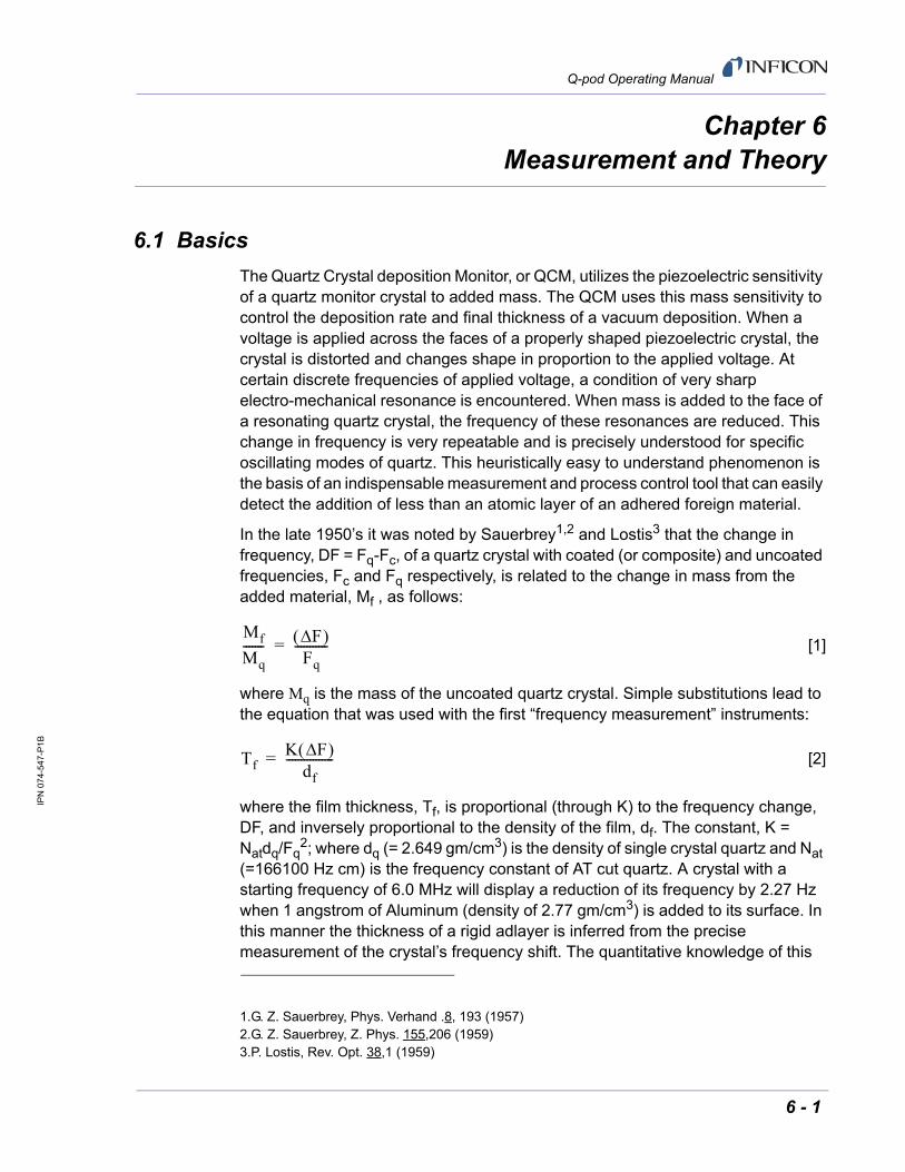
The Quartz Crystal deposition Monitor, or QCM, utilizes the piezoelectric sensitivity of a quartz monitor crystal to added mass. The QCM uses this mass sensitivity to control the deposition rate and final thickness of a vacuum deposition. When a voltage is applied across the faces of a properly shaped piezoelectric crystal, the crystal is distorted and changes shape in proportion to the applied voltage. At certain discrete frequencies of applied voltage, a condition of very sharp electro-mechanical resonance is encountered. When mass is added to the face of a resonating quartz crystal, the frequency of these resonances are reduced. This change in frequency is very repeatable and is precisely understood for specific oscillating modes of quartz. This heuristically easy to understand phenomenon is the basis of an indispensable measurement and process control tool that can easily detect the addition of less than an atomic layer of an adhered foreign material.
In the late 1950’s it was noted by Sauerbrey1,2 and Lostis3 that the change in frequency, DF = Fq-Fc, of a quartz crystal with coated (or composite) and uncoated frequencies, Fc and Fq respectively, is related to the change in mass from the added material, Mf , as follows:
[1]
where Mq is the mass of the uncoated quartz crystal. Simple substitutions lead to the equation that was used with the first “frequency measurement” instruments:
[2]
where the film thickness, Tf, is proportional (through K) to the frequency change, DF, and inversely proportional to the density of the film, df. The constant, K = Natdq/Fq
2; where dq (= 2.649 gm/cm3) is the density of single crystal quartz and Nat (=166100 Hz cm) is the frequency constant of AT cut quartz. A crystal with a starting frequency of 6.0 MHz will display a reduction of its frequency by 2.27 Hz when 1 angstrom of Aluminum (density of 2.77 gm/cm3) is added to its surface. In this manner the thickness of a rigid adlayer is inferred from the precise measurement of the crystal’s frequency shift. The quantitative knowledge of this
1.G. Z. Sauerbrey, Phys. Verhand .8, 193 (1957)2.G. Z. Sauerbrey, Z. Phys. 155,206 (1959)3.P. Lostis, Rev. Opt. 38,1 (1959)
Mf
Mq------- F
Fq-----------=
TfK F
df----------------=
6 - 1
IPN
07
4-54
7-P
1B
Q-pod Operating Manual
effect provides a means of determining how much material is being deposited on a substrate in a vacuum system, a measurement that was not convenient or practical prior to this understanding.
6.1.1 Monitor Crystals
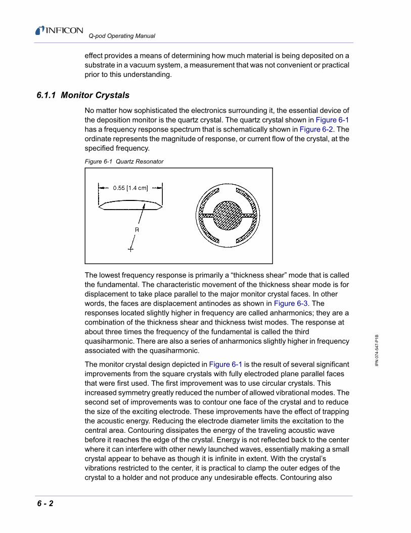
No matter how sophisticated the electronics surrounding it, the essential device of the deposition monitor is the quartz crystal. The quartz crystal shown in Figure 6-1 has a frequency response spectrum that is schematically shown in Figure 6-2. The ordinate represents the magnitude of response, or current flow of the crystal, at the specified frequency.
Figure 6-1 Quartz Resonator
The lowest frequency response is primarily a “thickness shear” mode that is called the fundamental. The characteristic movement of the thickness shear mode is for displacement to take place parallel to the major monitor crystal faces. In other words, the faces are displacement antinodes as shown in Figure 6-3. The responses located slightly higher in frequency are called anharmonics; they are a combination of the thickness shear and thickness twist modes. The response at about three times the frequency of the fundamental is called the third quasiharmonic. There are also a series of anharmonics slightly higher in frequency associated with the quasiharmonic.
The monitor crystal design depicted in Figure 6-1 is the result of several significant improvements from the square crystals with fully electroded plane parallel faces that were first used. The first improvement was to use circular crystals. This increased symmetry greatly reduced the number of allowed vibrational modes. The second set of improvements was to contour one face of the crystal and to reduce the size of the exciting electrode. These improvements have the effect of trapping the acoustic energy. Reducing the electrode diameter limits the excitation to the central area. Contouring dissipates the energy of the traveling acoustic wave before it reaches the edge of the crystal. Energy is not reflected back to the center where it can interfere with other newly launched waves, essentially making a small crystal appear to behave as though it is infinite in extent. With the crystal’s vibrations restricted to the center, it is practical to clamp the outer edges of the crystal to a holder and not produce any undesirable effects. Contouring also
6 - 2

IPN
07
4-54
7-P
1B
Q-pod Operating Manual
reduces the intensity of response of the generally unwanted anharmonic modes; hence, the potential for an oscillator to sustain an unwanted oscillation is substantially reduced.
Figure 6-2 Frequency Response Spectrum
The use of an adhesion layer has improved the electrode-to-quartz bonding, reducing “rate spikes” caused by micro-tears between the electrode and the quartz as film stress rises. These micro-tears leave portions of the deposited film unattached and therefore unable to participate in the oscillation. These free portions are no longer detected and the wrong thickness consequently inferred.
The “AT” resonator is usually chosen for deposition monitoring because at room temperature it can be made to exhibit a very small frequency change due to temperature changes. Since there is presently no way to separate the frequency change caused by added mass (which is negative) or even the frequency changes caused by temperature gradients across the crystal or film induced stresses, it is essential to minimize these temperature-induced changes. It is only in this way that small changes in mass can be measured accurately.
5.98
1 M
Hz
15 o
hm
6.15
3 M
Hz
50 o
hm6.
194
MH
z 40
ohm
6.33
3 M
Hz
142
ohm
6.33
7 M
Hz
105
ohm
6.34
8 M
Hz
322
ohm
6.41
9 M
Hz
350
ohm
17.7
92 M
Hz
278
ohm
17.9
57 M
Hz
311
ohm
18.1
33 M
Hz
350
ohm
Lo
g o
f re
lati
ve i
nte
ns
ity
(Ad
mit
tan
ce)
Frequency (in MHz)
110
1100
11000
6 7 17 18
6 - 3

IPN
07
4-54
7-P
1B
Q-pod Operating Manual
Figure 6-3 Thickness Shear Displacement
6.1.2 Period Measurement Technique
Although instruments using equation [2] were very useful, it was soon noted they had a very limited range of accuracy, typically holding accuracy for DF less than 0.02 Fq. In 1961 it was recognized by Behrndt4 that:
[3]
where Tc and Tq are the periods of oscillation of the crystal with film (composite) and the bare crystal respectively. The period measurement technique was the outgrowth of two factors; first, the digital implementation of time measurement, and second, the recognition of the mathematically rigorous formulation of the proportionality between the crystal’s thickness, Iq, and the period of oscillation, Tq = 1/Fq. Electronically the period measurement technique uses a second crystal oscillator, or reference oscillator, not affected by the deposition and usually much higher in frequency than the monitor crystal. This reference oscillator is used to generate small precision time intervals which are used to determine the oscillation period of the monitor crystal. This is done by using two pulse accumulators. The first is used to accumulate a fixed number of cycles, m, of the monitor crystal. The second is turned on at the same time and accumulates cycles from the reference oscillator until m counts are accumulated in the first. Since the frequency of the reference is stable and known, the time to accumulate the m counts is known to an accuracy equal to ± 2/Fr where Fr is the reference oscillator’s frequency. The
displacement nodeX
X
X
2
1
3
E
4.K. H. Behrndt, J. Vac. Sci. Technol. 8, 622 (1961)
Mf
Mq-------
Tc Tq– Tq
---------------------- F Fc
-----------= =
6 - 4

IPN
07
4-54
7-P
1B
Q-pod Operating Manual
monitor crystal’s period is (n/Fr)/m where n is the number of counts in the second accumulator. The precision of the measurement is determined by the speed of the reference clock and the length of the gate time (which is set by the size of m). Increasing one or both of these leads to improved measurement precision.
Having a high frequency reference oscillator is important for rapid measurements (which require short gating times), low deposition rates and low density materials. All of these require high time precision to resolve the small, mass induced frequency shifts between measurements. When the change of a monitor crystal’s frequency between measurements is small, that is, on the same order of size as the measurement precision, it is not possible to establish quality rate control. The uncertainty of the measurement injects more noise into the control loop, which can be counteracted only by longer time constants. Long time constants cause the correction of rate errors to be very slow, resulting in relatively long term deviations from the desired rate. These deviations may not be important for some simple films, but can cause unacceptable errors in the production of critical films such as optical filters or very thin layered superlattices grown at low rates. In many cases the desired properties of these films can be lost if the layer to layer reproducibility exceeds one, or two, percent. Ultimately, the practical stability and frequency of the reference oscillator limits the precision of measurement for conventional instrumentation.
6.1.3 Z-match Technique
After learning of fundamental work by Miller and Bolef 5, which rigorously treated the resonating quartz and deposited film system as a one-dimensional continuous acoustic resonator, Lu and Lewis6 developed the simplifying Z-match™ equation in 1972. Advances in electronics taking place at the same time, namely the micro-processor, made it practical to solve the Z-match equation in “real-time”. Most deposition process controllers/monitors sold today use this sophisticated equation that takes into account the acoustic properties of the resonating quartz and film system as shown in equation [4].
[4]
where Z=(dquq/dfuf)1/2 is the acoustic impedance ratio and uq and uf are the shear
moduli of the quartz and film, respectively. Finally, there was a fundamental understanding of the frequency-to-thickness conversion that could yield theoretically correct results in a time frame that was practical for process control. To achieve this new level of accuracy requires only that the user enter an additional material parameter, Z, for the film being deposited. This equation has been tested
5.J. G. Miller and D. I. Bolef, J. Appl. Phys. 39, 5815, 4589 (1968)6.C. Lu and O. Lewis, J Appl. Phys. 43, 4385 (1972)
Tf
Natdq
dfFcZ------------------ arctan Z tan
Fq Fc– Fq
------------------------- =
6 - 5

IPN
07
4-54
7-P
1B
Q-pod Operating Manual
for a number of materials, and has been found to be valid for frequency shifts equivalent to Ff = 0.4Fq. Keep in mind that equation [2] was valid to only 0.02Fq and equation [3] was valid only to ~0.05Fq.
6.1.4 Active Oscillator
The Q-pod relies on the use of an active oscillator circuit, Specifically the type schematically shown in Figure 6-4. This circuit actively keeps the crystal in resonance, so that any type of period or frequency measurement may be made. In this type of circuit, oscillation is sustained as long as the gain provided by the amplifiers is sufficient to offset losses in the crystal and circuit and the crystal can provide the required phase shift. The basic crystal oscillator’s stability is derived from the rapid change of phase for a small change in the crystal’s frequency near the series resonance point, as shown in Figure 6-6 on page 6-7.
Figure 6-4 Active Oscillator Circuit
The active oscillator circuit is designed so the crystal is required to produce a phase shift of 0 degrees, which allows it to operate at the series resonance point. Long- and short-term frequency stabilities are a property of crystal oscillators because very small frequency changes are needed to sustain the phase shift required for oscillation. Frequency stability is provided by the quartz crystal even though there are long term changes in electrical component values caused by temperature or aging or short-term noise-induced phase jitter.
As mass is added to a crystal, its electrical characteristics change. Figure 6-5 on page 6-7 is the same plot as Figure 6-6 overlaid with the response of a heavily loaded crystal.
6 - 6
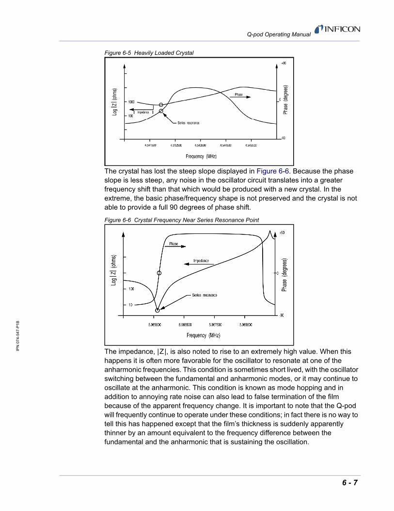
IPN
07
4-54
7-P
1B
Q-pod Operating Manual
Figure 6-5 Heavily Loaded Crystal
The crystal has lost the steep slope displayed in Figure 6-6. Because the phase slope is less steep, any noise in the oscillator circuit translates into a greater frequency shift than that which would be produced with a new crystal. In the extreme, the basic phase/frequency shape is not preserved and the crystal is not able to provide a full 90 degrees of phase shift.
Figure 6-6 Crystal Frequency Near Series Resonance Point
The impedance, |Z|, is also noted to rise to an extremely high value. When this happens it is often more favorable for the oscillator to resonate at one of the anharmonic frequencies. This condition is sometimes short lived, with the oscillator switching between the fundamental and anharmonic modes, or it may continue to oscillate at the anharmonic. This condition is known as mode hopping and in addition to annoying rate noise can also lead to false termination of the film because of the apparent frequency change. It is important to note that the Q-pod will frequently continue to operate under these conditions; in fact there is no way to tell this has happened except that the film’s thickness is suddenly apparently thinner by an amount equivalent to the frequency difference between the fundamental and the anharmonic that is sustaining the oscillation.
6 - 7

IPN
07
4-54
7-P
1B
Q-pod Operating Manual
This page is intentionally blank.
6 - 8

IPN
07
4-54
7-P
1B
Q-pod Operating Manual
Appendix AMaterial Table
A.1 Introduction
The following Table A-1 represents the density and Z-Ratio for various materials. The list is alphabetical by chemical formula.
CAUTION
Some of these materials are toxic. Please consult the material safety data sheet and safety instructions before use.
An * is used to indicate that a Z-ratio has not been established for a certain material. A value of 1.000 is defaulted in these situations.
Table A-1 Material Table
Formula Density Z-Ratio Material Name
Ag 10.500 0.529 silver
AgBr 6.470 1.180 silver bromide
AgCl 5.560 1.320 silver chloride
Al 2.700 1.080 aluminum
Al2O3 3.970 0.336 aluminum oxide
Al4C3 2.360 *1.000 aluminum carbide
AIF3 3.070 *1.000 aluminum fluoride
AIN 3.260 *1.000 aluminum nitride
AlSb 4.360 0.743 aluminum antimonide
As 5.730 0.966 arsenic
As2Se3 4.750 *1.000 arsenic selenide
Au 19.300 0.381 gold
B 2.370 0.389 boron
B203 1.820 *1.000 boron oxide
B4C 2.370 *1.000 boron carbide
BN 1.860 *1.000 boron nitride
Ba 3.500 2.100 barium
BaF2 4.886 0.793 barium fluoride
PRELIMINARY 5/4/12 A - 1

IPN
07
4-54
7-P
1B
Q-pod Operating Manual
BaN2O6 3.244 1.261 barium nitrate
BaO 5.720 *1.000 barium oxide
BaTiO3 5.999 0.464 barium titanate (tetr)
BaTiO3 6.035 0.412 barium titanate (cubic)
Be 1.850 0.543 beryllium
BeF2 1.990 *1.000 beryllium fluoride
BeO 3.010 *1.000 beryllium oxide
Bi 9.800 0.790 bismuth
Bi2O3 8.900 *1.000 bismuth oxide
Bi2S3 7.390 *1.000 bismuth trisulphide
Bi2Se3 6.820 *1.000 bismuth selenide
Bi2Te3 7.700 *1.000 bismuth telluride
BiF3 5.320 *1.000 bismuth fluoride
C 2.250 3.260 carbon (graphite)
C 3.520 0.220 carbon (diamond)
C8H8 1.100 *1.000 parlyene (union carbide)
Ca 1.550 2.620 calcium
CaF2 3.180 0.775 calcium fluoride
CaO 3.350 *1.000 calcium oxide
CaO-SiO2 2.900 *1.000 calcium silicate (3)
CaSO4 2.962 0.955 calcium sulfate
CaTiO3 4.100 *1.000 calcium titanate
CaWO4 6.060 *1.000 calcium tungstate
Cd 8.640 0.682 cadmium
CdF2 6.640 *1.000 cadmium fluoride
CdO 8.150 *1.000 cadmium oxide
CdS 4.830 1.020 cadmium sulfide
CdSe 5.810 *1.000 cadmium selenide
CdTe 6.200 0.980 cadmium telluride
Ce 6.780 *1.000 cerium
CeF3 6.160 *1.000 cerium (III) fluoride
CeO2 7.130 *1.000 cerium (IV) dioxide
Co 8.900 0.343 cobalt
Table A-1 Material Table (continued)
Formula Density Z-Ratio Material Name
A - 2 PRELIMINARY 5/4/12

IPN
07
4-54
7-P
1B
Q-pod Operating Manual
CoO 6.440 0.412 cobalt oxide
Cr 7.200 0.305 chromium
Cr2O3 5.210 *1.000 chromium (III) oxide
Cr3C2 6.680 *1.000 chromium carbide
CrB 6.170 *1.000 chromium boride
Cs 1.870 *1.000 cesium
Cs2SO4 4.243 1.212 cesium sulfate
CsBr 4.456 1.410 cesium bromide
CsCI 3.988 1.399 cesium chloride
CsI 4.516 1.542 cesium iodide
Cu 8.930 0.437 copper
Cu2O 6.000 *1.000 copper oxide
Cu2S 5.600 0.690 copper (I) sulfide (alpha)
Cu2S 5.800 0.670 copper (I) sulfide (beta)
CuS 4.600 0.820 copper (II) sulfide
Dy 8.550 0.600 dysprosium
DY2O3 7.810 *1.000 dysprosium oxide
Er 9.050 0.740 erbium
Er2O3 8.640 *1.000 erbium oxide
Eu 5.260 *1.000 europium
EuF2 6.500 *1.000 europium fluoride
Fe 7.860 0.349 iron
Fe2O3 5.240 *1.000 iron oxide
FeO 5.700 *1.000 iron oxide
FeS 4.840 *1.000 iron sulphide
Ga 5.930 0.593 gallium
Ga2O3 5.880 *1.000 gallium oxide (b)
GaAs 5.310 1.590 gallium arsenide
GaN 6.100 *1.000 gallium nitride
GaP 4.100 *1.000 gallium phosphide
GaSb 5.600 *1.000 gallium antimonide
Gd 7.890 0.670 gadolinium
Gd2O3 7.410 *1.000 gadolinium oxide
Table A-1 Material Table (continued)
Formula Density Z-Ratio Material Name
PRELIMINARY 5/4/12 A - 3

IPN
07
4-54
7-P
1B
Q-pod Operating Manual
Ge 5.350 0.516 germanium
Ge3N2 5.200 *1.000 germanium nitride
GeO2 6.240 *1.000 germanium oxide
GeTe 6.200 *1.000 germanium telluride
Hf 13.090 0.360 hafnium
HfB2 10.500 *1.000 hafnium boride
HfC 12.200 *1.000 hafnium carbide
HfN 13.800 *1.000 hafnium nitride
HfO2 9.680 *1.000 hafnium oxide
HfSi2 7.200 *1.000 hafnium silicide
Hg 13.460 0.740 mercury
Ho 8.800 0.580 holminum
Ho2O3 8.410 *1.000 holminum oxide
In 7.300 0.841 indium
In2O3 7.180 *1.000 indiurn sesquioxide
In2Se3 5.700 *1.000 indium selenide
In2Te3 5.800 *1.000 indium telluride
InAs 5.700 *1.000 indium arsenide
InP 4.800 *1.000 indium phosphide
InSb 5.760 0.769 indium antimonide
Ir 22.400 0.129 iridium
K 0.860 10.189 potassium
KBr 2.750 1.893 potassium bromide
KCI 1.980 2.050 potassium chloride
KF 2.480 *1.000 potassium fluoride
KI 3.128 2.077 potassium iodide
La 6.170 0.920 lanthanum
La2O3 6.510 *1.000 lanthanum oxide
LaB6 2.610 *1.000 lanthanurn boride
LaF3 5.940 *1.000 lanthanum fluoride
Li 0.530 5.900 lithium
LiBr 3.470 1.230 lithium bromide
LiF 2.638 0.778 lithium fluoride
Table A-1 Material Table (continued)
Formula Density Z-Ratio Material Name
A - 4 PRELIMINARY 5/4/12

IPN
07
4-54
7-P
1B
Q-pod Operating Manual
LiNbO3 4.700 0.463 lithium niobate
Lu 9.840 *1.000 lutetium
Mg 1.740 1.610 magnesium
MgAl2O4 3.600 *1.000 magnesium aluminate
MgAl2O6 8.000 *1.000 spinel
MgF2 3.180 0.637 magnesium fluoride
MgO 3.580 0.411 magnesium oxide
Mn 7.200 0.377 manganese
MnO 5.390 0.467 manganese oxide
MnS 3.990 0.940 manganese (II) sulfide
Mo 10.200 0.257 molybdenum
Mo2C 9.180 *1.000 molybdenum carbide
MoB2 7.120 *1.000 molybdenum boride
MoO3 4.700 *1.000 molybdenum trioxdide
MoS2 4.800 *1.000 molybdenum disulfide
Na 0.970 4.800 sodium
Na3AIF6 2.900 *1.000 cryolite
Na5Al3F14 2.900 *1.000 chiolite
NaBr 3.200 *1.000 sodium bromide
NaCl 2.170 1.570 sodium chloride
NaCIO3 2.164 1.565 sodium chlorate
NaF 2.558 1.645 sodium fluoride
NaNO3 2.270 1.194 sodium nitrate
Nb 8.578 0.492 niobium (columbium)
Nb2O3 7.500 *1.000 niobium trioxide
Nb2O5 4.470 *1.000 niobium (V) oxide
NbB2 6.970 *1.000 niobium boride
NbC 7.820 *1.000 niobium carbide
NbN 8.400 *1.000 niobium nitride
Nd 7.000 *1.000 neodynium
Nd2O3 7.240 *1.000 neodynium oxide
NdF3 6.506 *1.000 neodynium fluoride
Ni 8.910 0.331 nickel
Table A-1 Material Table (continued)
Formula Density Z-Ratio Material Name
PRELIMINARY 5/4/12 A - 5

IPN
07
4-54
7-P
1B
Q-pod Operating Manual
NiCr 8.500 *1.000 nichrome
NiCrFe 8.500 *1.000 inconel
NiFe 8.700 *1.000 permalloy
NiFeMo 8.900 *1.000 supermalloy
NiO 7.450 *1.000 nickel oxide
P3N5 2.510 *1.000 phosphorus nitride
Pb 11.300 1.130 lead
PbCl2 5.850 *1.000 lead chloride
PbF2 8.240 0.661 lead fluoride
PbO 9.530 *1.000 lead oxide
PbS 7.500 0.566 lead sulfide
PbSe 8.100 *1.000 lead selenide
PbSnO3 8.100 *1.000 lead stannate
PbTe 8.160 0.651 lead telluride
Pd 12.038 0.357 palladium
PdO 8.310 *1.000 palladium oxide
Po 9.400 *1.000 polonium
Pr 6.780 *1.000 praseodymium
Pr2O3 6.880 *1.000 praseodymium oxide
Pt 21.400 0.245 platinum
PtO2 10.200 *1.000 platinum oxide
Ra 5.000 *1.000 radium
Rb 1.530 2.540 rubidium
RbI 3.550 *1.000 rubidiurn iodide
Re 21.040 0.150 rhenium
Rh 12.410 0.210 rhodium
Ru 12.362 0.182 ruthenium
S8 2.070 2.290 sulphur
Sb 6.620 0.768 antimony
Sb2O3 5.200 *1.000 antimony trioxide
Sb2S3 4.640 *1.000 antimony trisulfide
Sc 3.000 0.910 scandium
Sc2O3 3.860 *1.000 scandium oxide
Table A-1 Material Table (continued)
Formula Density Z-Ratio Material Name
A - 6 PRELIMINARY 5/4/12

IPN
07
4-54
7-P
1B
Q-pod Operating Manual
Se 4.810 0.864 selenium
Si 2.320 0.712 silicon
Si3N4 3.440 *1.000 silicon nitride
SiC 3.220 *1.000 silicon carbide
SiO 2.130 0.870 silicon (ii) oxide
SiO2 2.648 1.000 silicon dioxide
Sm 7.540 0.890 samarium
Sm2O3 7.430 *1.000 samarium oxide
Sn 7.300 0.724 tin
SnO2 6.950 *1.000 tin oxide
SnS 5.080 *1.000 tin sulfide
SnSe 6.180 *1.000 tin selenide
SnTe 6.440 *1.000 tin telluride
Sr 2.600 *1.000 strontium
SrF2 4.277 0.727 strontium fluroide
SrO 4.990 0.517 strontium oxide
Ta 16.600 0.262 tantalum
Ta2O5 8.200 0.300 tantalum (v) oxide
TaB2 11.150 *1.000 tantalum boride
TaC 13.900 *1.000 tantalum carbide
TaN 16.300 *1.000 tantalum nitride
Tb 8.270 0.660 terbium
Tc 11.500 *1.000 technetium
Te 6.250 0.900 tellurium
TeO2 5.990 0.862 tellurium oxide
Th 11.694 0.484 thorium
ThF4 6.320 *1.000 thorium.(IV) fluoride
ThO2 9.860 0.284 thorium dioxide
ThOF2 9.100 *1.000 thorium oxyfluoride
Ti 4.500 0.628 titanium
Ti203 4.600 *1.000 titanium sesquioxide
TiB2 4.500 *1.000 titanium boride
TiC 4.930 *1.000 titanium carbide
Table A-1 Material Table (continued)
Formula Density Z-Ratio Material Name
PRELIMINARY 5/4/12 A - 7

IPN
07
4-54
7-P
1B
Q-pod Operating Manual
TiN 5.430 *1.000 titanium nitride
TiO 4.900 *1.000 titanium oxide
TiO2 4.260 0.400 titanium (iv) oxide
TI 11.850 1.550 thallium
TIBr 7.560 *1.000 thallium bromide
TICI 7.000 *1.000 thallium chloride
TII 7.090 *1.000 thalliurn iodide (b)
U 19.050 0.238 uranium
U3O8 8.300 *1.000 tri uranium octoxide
U4O9 10.969 0.348 uranium oxide
UO2 10.970 0.286 uranium dioxide
V 5.960 0.530 vanadium
V2O5 3.360 *1.000 vanadium pentoxide
VB2 5.100 *1.000 vanadium boride
VC 5.770 *1.000 vanadium carbide
VN 6.130 *1.000 vanadium nitride
VO2 4.340 *1.000 vanadium dioxide
W 19.300 0.163 tungsten
WB2 10.770 *1.000 tungsten boride
WC 15.600 0.151 tungsten carbide
WO3 7.160 *1.000 tungsten trioxide
WS2 7.500 *1.000 tungsten disulphide
WSi2 9.400 *1.000 tungsten silicide
Y 4.340 0.835 yttrium
Y203 5.010 *1.000 yttrium oxide
Yb 6.980 1.130 ytterbium
Yb2O3 9.170 *1.000 ytterbium oxide
Zn 7.040 0.514 zinc
Zn3Sb2 6.300 *1.000 zinc antimonide
ZnF2 4.950 *1.000 zinc fluoride
ZnO 5.610 0.556 zinc oxide
ZnS 4.090 0.775 zinc sulfide
ZnSe 5.260 0.722 zinc selenide
Table A-1 Material Table (continued)
Formula Density Z-Ratio Material Name
A - 8 PRELIMINARY 5/4/12
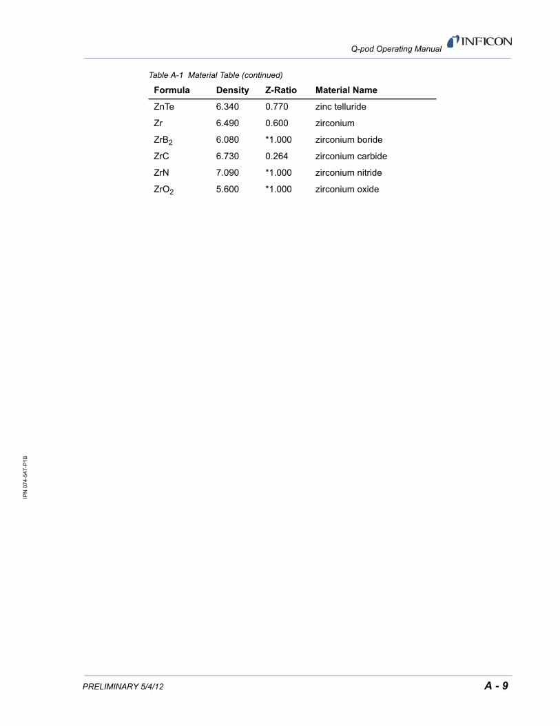
IPN
07
4-54
7-P
1B
Q-pod Operating Manual
ZnTe 6.340 0.770 zinc telluride
Zr 6.490 0.600 zirconium
ZrB2 6.080 *1.000 zirconium boride
ZrC 6.730 0.264 zirconium carbide
ZrN 7.090 *1.000 zirconium nitride
ZrO2 5.600 *1.000 zirconium oxide
Table A-1 Material Table (continued)
Formula Density Z-Ratio Material Name
PRELIMINARY 5/4/12 A - 9

IPN
07
4-54
7-P
1B
Q-pod Operating Manual
This page is intentionally blank.
A - 10 PRELIMINARY 5/4/12


![DV-074-DVDVRUR[Guadalajara 1] 074 1](https://img.pdfslide.net/doc/110x75/62d4aa2ad468aa181f327a9f/dv-074-dvdvrurguadalajara-1-074-1.jpg)