Embed Size (px)
Citation preview
® Specif icat ion Submittal page 1
Job Name:
Job Number:
Model Numbers:
Energi Savr NodeTM QSN-2ECO-PS120 EcoSystem® with Shades ESN
085-255a 1 08.26.10
PRELIMINARY
EcoSystem® with shades Energi Savr Node™
The EcoSystem with Shades Energi Savr Node™ (ESN) (QSN –2ECO-PS120) is an integrated lights and shades panel. This document describes the EcoSystem with Shades ESN, which can control all EcoSystem-compatible products and provides power and communication for QS shades/draperies. It can be used to integrate lighting and shading products in one convenient location. The EcoSystem with Shades ESN is able to control EcoSystem ballasts and modules, Hi-Lume® 3D ballasts, EcoSystem H-Series ballasts, Hi-Lume LED and Hi-LumeA series LED drivers while providing ten fused 30 W (60 W peak) 24V outputs for QS shades/draperies. The QSN-2ECO-PS120 is designed to be hardwired into a standard 120 V~ circuit.
Features• 24 V supply that provides power to QS shades, drapery
drive units, keypads, and accessories• Controls up to 128 EcoSystem Ballasts• Simple wiring scheme uses 4-conductor low voltage link
to provide power and communication for QS devices• Flexible wiring topology for easy installation and integration• 10 output panel provides power for 10 to 30 shades
based on shade dimensions• Smart diagnostics reduce installation time and
system verification• Confirms system communication and facilitates
system installation• Provides easy system testing with manual override buttons
for shades and lighting
® Specif icat ion Submittal page 2
Job Name:
Job Number:
Model Numbers:
Energi Savr NodeTM QSN-2ECO-PS120 EcoSystem® with Shades ESN
085-255a 2 08.26.10
PRELIMINARY
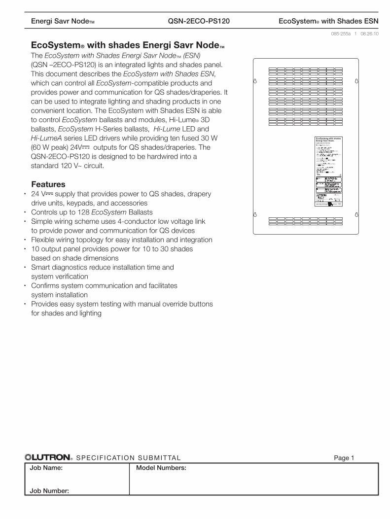
Power Input 120 V
Emergency Contact Closure
Input
Programmable Contact Closure Input
Wired EcoSystem Daylight Sensors (up to 4)
(2) EcoSystem Digital Links (up to 64 ballasts each)
Wired EcoSystem Occupancy Sensors (up to 4)
Wired EcoSystem Wallstations or EcoSystem IR receivers (up to 4)
QS Shades/Draperies (up to10)
System Overview
® Specif icat ion Submittal page 3
Job Name:
Job Number:
Model Numbers:
Energi Savr NodeTM QSN-2ECO-PS120 EcoSystem® with Shades ESN
085-255a 3 08.26.10
PRELIMINARY
Specifications
Power• 120 V~ 60 Hz input voltage• 8 A / Panel Note: Use only high magnetic breakers• 1 panel per dedicated 15 A circuit or 2 panels
per dedicated 20 A circuit • 30 A maximum breaker size• Lightning strike protection meets ANSI/IEEE
standard 62.31-1980. Can withstand voltage surges of up to 6000 V and current surges of up to 3000 A
• (+/-) 16kV ESD protection• QS Link Output: 24 V• Fuse on each shade output
2 spares included (5x20mm, 2.5 A fuse) for miswire protection
• 10-year power failure memory: restores lighting to levels prior to power interruption
Regulatory Approvals UL Listed: #E42071
• Lutron® Quality Systems registered to ISO 9001.2000
• UL 508 Limited Voltage/Limited Current Circuit (NEC® approved class 2 power source)
Environment• Ambient Temperature Operating Range:
32º F to 104ºF (0 ºC to 40 ºC)• Relative humidity: less than 90% non-condensing• For indoor use only
Terminals EcoSystem Link• EcoSystem Digital Link Wiring:
18 AWG–12 AWG (1.0 mm2–2.5 mm2)• Sensor Wiring: 22 AWG–12 AWG
(0.5 mm2–2.5 mm2)
QS Link• 10-14 AWG (6-2.5 mm²) stranded input wiring• 4 conductor 12-26 AWG (4-0.15 mm²) stranded,
twisted/shielded ouput wiring
Mounting• Surface mount• 35 lbs (15.8 kg)
® Specif icat ion Submittal page 4
Job Name:
Job Number:
Model Numbers:
Energi Savr NodeTM QSN-2ECO-PS120 EcoSystem® with Shades ESN
085-255a 4 08.26.10
PRELIMINARY
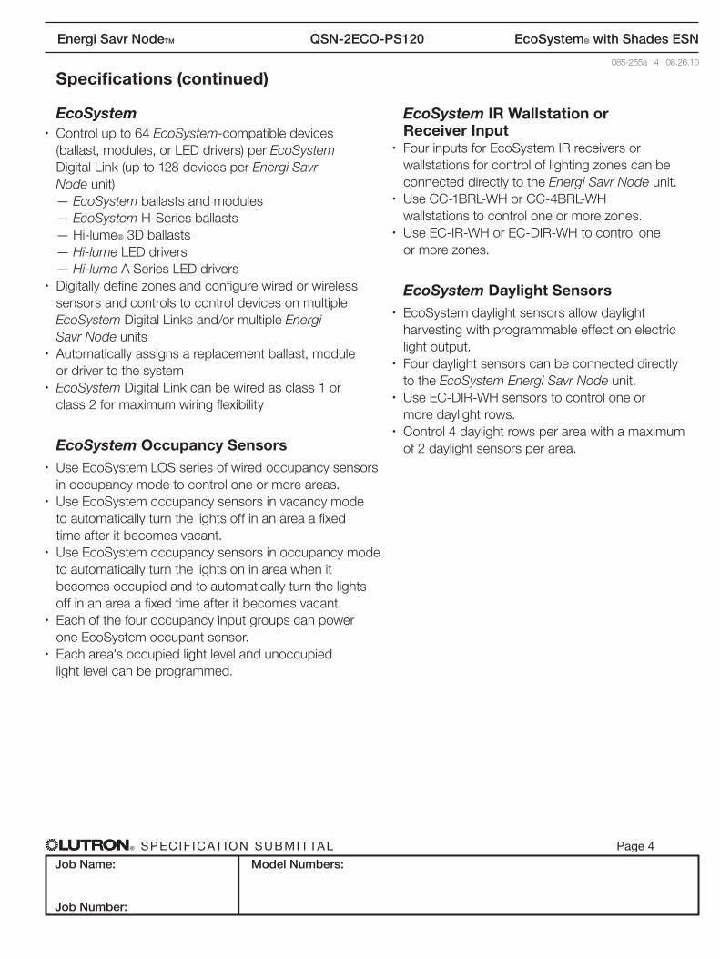
Specifications (continued) EcoSystem
• Control up to 64 EcoSystem-compatible devices (ballast, modules, or LED drivers) per EcoSystem Digital Link (up to 128 devices per Energi Savr Node unit)
— EcoSystem ballasts and modules — EcoSystem H-Series ballasts — Hi-lume® 3D ballasts — Hi-lume LED drivers — Hi-lume A Series LED drivers• Digitally define zones and configure wired or wireless
sensors and controls to control devices on multiple EcoSystem Digital Links and/or multiple Energi Savr Node units
• Automatically assigns a replacement ballast, module or driver to the system
• EcoSystem Digital Link can be wired as class 1 or class 2 for maximum wiring flexibility
EcoSystem Occupancy Sensors• Use EcoSystem LOS series of wired occupancy sensors
in occupancy mode to control one or more areas.• Use EcoSystem occupancy sensors in vacancy mode
to automatically turn the lights off in an area a fixed time after it becomes vacant.
• Use EcoSystem occupancy sensors in occupancy mode to automatically turn the lights on in area when it becomes occupied and to automatically turn the lights off in an area a fixed time after it becomes vacant.
• Each of the four occupancy input groups can power one EcoSystem occupant sensor.
• Each area's occupied light level and unoccupied light level can be programmed.
EcoSystem IR Wallstation or Receiver Input
• Four inputs for EcoSystem IR receivers or wallstations for control of lighting zones can be connected directly to the Energi Savr Node unit.
• Use CC-1BRL-WH or CC-4BRL-WH wallstations to control one or more zones.
• Use EC-IR-WH or EC-DIR-WH to control one or more zones.
EcoSystem Daylight Sensors• EcoSystem daylight sensors allow daylight
harvesting with programmable effect on electric light output.
• Four daylight sensors can be connected directly to the EcoSystem Energi Savr Node unit.
• Use EC-DIR-WH sensors to control one or more daylight rows.
• Control 4 daylight rows per area with a maximum of 2 daylight sensors per area.
® Specif icat ion Submittal page 5
Job Name:
Job Number:
Model Numbers:
Energi Savr NodeTM QSN-2ECO-PS120 EcoSystem® with Shades ESN
085-255a 5 08.26.10
PRELIMINARY
Specifications (continued)
Contact Closure Input (CCI)• Activate lighting scenes using momentary or
maintained closures from an external device like a timeclock.
• Start or stop Afterhours mode.• Enable or disable Load Shed mode to save energy
during peak demand periods.• The attached device must provide a dry contact
closure or solid state output. The input can be configured as normally open (NO) or normally closed (NC). The default configuration is normally closed.
• Input is miswire-protected up to 36 V .
Emergency Contact Closure Input• By default, contact closure input from LUT-ELI,
security, or fire alarm systems turns all lighting zones on to full output when emergency state is activated.
• Response of each lighting zone is configurable.• No operations will be allowed until emergency signal
is cleared.• The attached device must provide a dry contact
closure or solid-state output.• Input is miswire-protected up to 36 V .
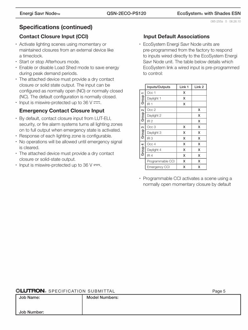
Input Default Associations• EcoSystem Energi Savr Node units are
pre-programmed from the factory to respond to inputs wired directly to the EcoSystem Energi Savr Node unit. The table below details which EcoSystem link a wired input is pre-programmed to control:
Inputs/Outputs Link 1 Link 2
Gro
up 1 Occ 1 X
Daylight 1 X
IR 1 X
Gro
up 2 Occ 2 X
Daylight 2 X
IR 2 X
Gro
up 3 Occ 3 X X
Daylight 3 X X
IR 3 X XG
roup
4 Occ 4 X X
Daylight 4 X X
IR 4 X X
Programmable CCI X X
Emergency CCI X X
• Programmable CCI activates a scene using a normally open momentary closure by default
® Specif icat ion Submittal page 6
Job Name:
Job Number:
Model Numbers:
Energi Savr NodeTM QSN-2ECO-PS120 EcoSystem® with Shades ESN
085-255a 6 08.26.10
PRELIMINARY
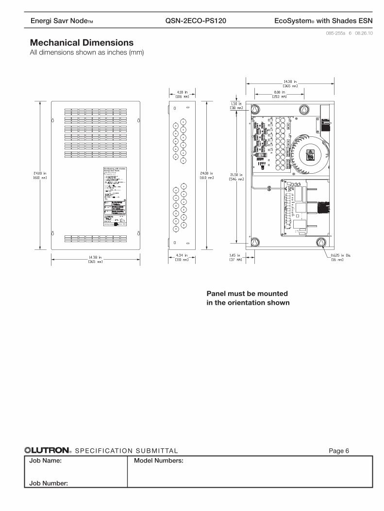
Mechanical Dimensions All dimensions shown as inches (mm)
Panel must be mounted in the orientation shown
® Specif icat ion Submittal page 7
Job Name:
Job Number:
Model Numbers:
Energi Savr NodeTM QSN-2ECO-PS120 EcoSystem® with Shades ESN
085-255a 7 08.26.10
PRELIMINARY
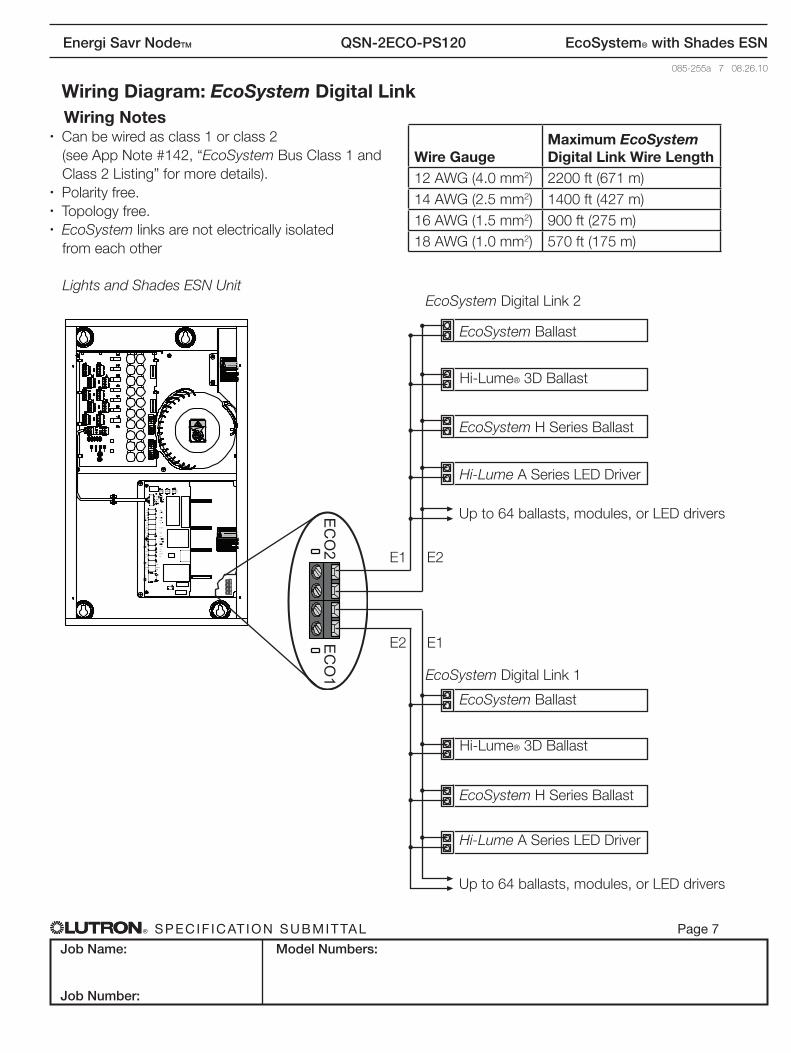
Wiring Diagram: EcoSystem Digital Link
EcoSystem Ballast
Lights and Shades ESN UnitEcoSystem Digital Link 2
EcoSystem Digital Link 1
EcoSystem Ballast
Hi-Lume® 3D Ballast
Hi-Lume® 3D Ballast
EcoSystem H Series Ballast
EcoSystem H Series Ballast
Hi-Lume A Series LED Driver
Hi-Lume A Series LED Driver
Up to 64 ballasts, modules, or LED drivers
Up to 64 ballasts, modules, or LED drivers
Wiring Notes• Can be wired as class 1 or class 2 (see App Note #142, “EcoSystem Bus Class 1 and Class 2 Listing” for more details).• Polarity free.• Topology free.• EcoSystem links are not electrically isolated from each other
Wire GaugeMaximum EcoSystem Digital Link Wire Length
12 AWG (4.0 mm2) 2200 ft (671 m)14 AWG (2.5 mm2) 1400 ft (427 m)16 AWG (1.5 mm2) 900 ft (275 m)18 AWG (1.0 mm2) 570 ft (175 m)
E1 E2
E2 E1
EC
O2
EC
O1
EC
O2
EC
O1
® Specif icat ion Submittal page 8
Job Name:
Job Number:
Model Numbers:
Energi Savr NodeTM QSN-2ECO-PS120 EcoSystem® with Shades ESN
085-255a 8 08.26.10
PRELIMINARY
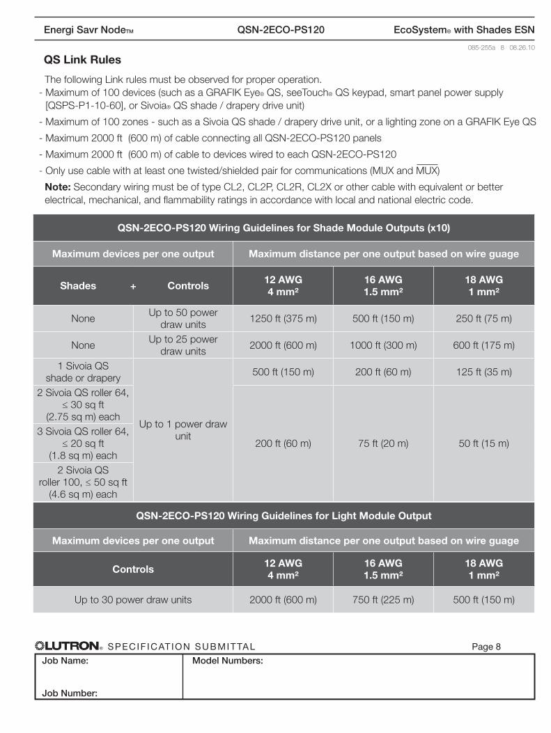
QS Link Rules
QSN-2ECO-PS120 Wiring Guidelines for Shade Module Outputs (x10)
Maximum devices per one output Maximum distance per one output based on wire guage
Shades + Controls 12 AWG4 mm²
16 AWG1.5 mm²
18 AWG1 mm²
NoneUp to 50 power
draw units1250 ft (375 m) 500 ft (150 m) 250 ft (75 m)
NoneUp to 25 power
draw units2000 ft (600 m) 1000 ft (300 m) 600 ft (175 m)
1 Sivoia QSshade or drapery
Up to 1 power draw unit
500 ft (150 m) 200 ft (60 m) 125 ft (35 m)
2 Sivoia QS roller 64, ≤ 30 sq ft
(2.75 sq m) each
200 ft (60 m) 75 ft (20 m) 50 ft (15 m)3 Sivoia QS roller 64,
≤ 20 sq ft (1.8 sq m) each
2 Sivoia QS roller 100, ≤ 50 sq ft
(4.6 sq m) each
The following Link rules must be observed for proper operation. - Maximum of 100 devices (such as a GRAFIK Eye® QS, seeTouch® QS keypad, smart panel power supply
[QSPS-P1-10-60], or Sivoia® QS shade / drapery drive unit)
- Maximum of 100 zones - such as a Sivoia QS shade / drapery drive unit, or a lighting zone on a GRAFIK Eye QS
- Maximum 2000 ft (600 m) of cable connecting all QSN-2ECO-PS120 panels
- Maximum 2000 ft (600 m) of cable to devices wired to each QSN-2ECO-PS120
- Only use cable with at least one twisted/shielded pair for communications (MUX and MUX)
Note: Secondary wiring must be of type CL2, CL2P, CL2R, CL2X or other cable with equivalent or better electrical, mechanical, and flammability ratings in accordance with local and national electric code.
QSN-2ECO-PS120 Wiring Guidelines for Light Module Output
Maximum devices per one output Maximum distance per one output based on wire guage
Controls 12 AWG4 mm²
16 AWG1.5 mm²
18 AWG1 mm²
Up to 30 power draw units 2000 ft (600 m) 750 ft (225 m) 500 ft (150 m)
® Specif icat ion Submittal page 9
Job Name:
Job Number:
Model Numbers:
Energi Savr NodeTM QSN-2ECO-PS120 EcoSystem® with Shades ESN
085-255a 9 08.26.10
PRELIMINARY
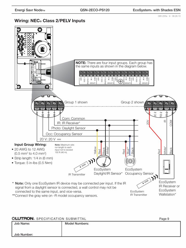
Wiring: NEC® Class 2/PELV Inputs
GROUP 1+2
0V
OC
C 1
PH
OTO
1
IR 1
CO
M
GROUP 2
+20V
OC
C 2
PH
OTO
2
IR 2
CO
M
GROUP 3
+20V
OC
C 3
PH
OTO
3IR
3
CO
M
GROUP 4
+20V
OC
C 4
PH
OTO
4
IR 4
CO
M
NOTE: There are four input groups. Each group has the same inputs as shown in the diagram below.
Note: Maximum wire run length to each input not to exceed 150 ft (46 m).
Input Group Wiring:• 20 AWG to 12 AWG
(0.5 mm2 to 4.0 mm2)• Strip length: 1/4 in (6 mm)• Torque: 5 in-lbs (0.5 N•m)
* Note: Only one EcoSystem IR device may be connected per input. If the IR signal from a daylight sensor is connected, a wall control may not be connected to the same input, and vice-versa.
** Connect the gray wire on -R model occupancy sensors.
+20V
CC
1
TO 1
IR 1
CO
M
CO
M
+20V
CC
2
TO 2
IR 2
CO
MEcoSystemOccupancy Sensor
EcoSystemIR Receiver orEcoSystemWallstation*
Red
Red
20V
Bla
ck
Bla
ckC
OM
Yello
w
Blu
e**
Bla
ck
Red
Whi
te*
20 V: 20 V
Occ: Occupancy Sensor
Photo: Daylight Sensor
IR: IR Receiver*Com: Common
Group 1 shown Group 2 shown
Whi
te*
IR
LUTRON
EcoSystemDaylight/IR Sensor*
EcoSystemIR Transmitter
IR Transmitter
® Specif icat ion Submittal page 10
Job Name:
Job Number:
Model Numbers:
Energi Savr NodeTM QSN-2ECO-PS120 EcoSystem® with Shades ESN
085-255a 10 08.26.10
PRELIMINARY
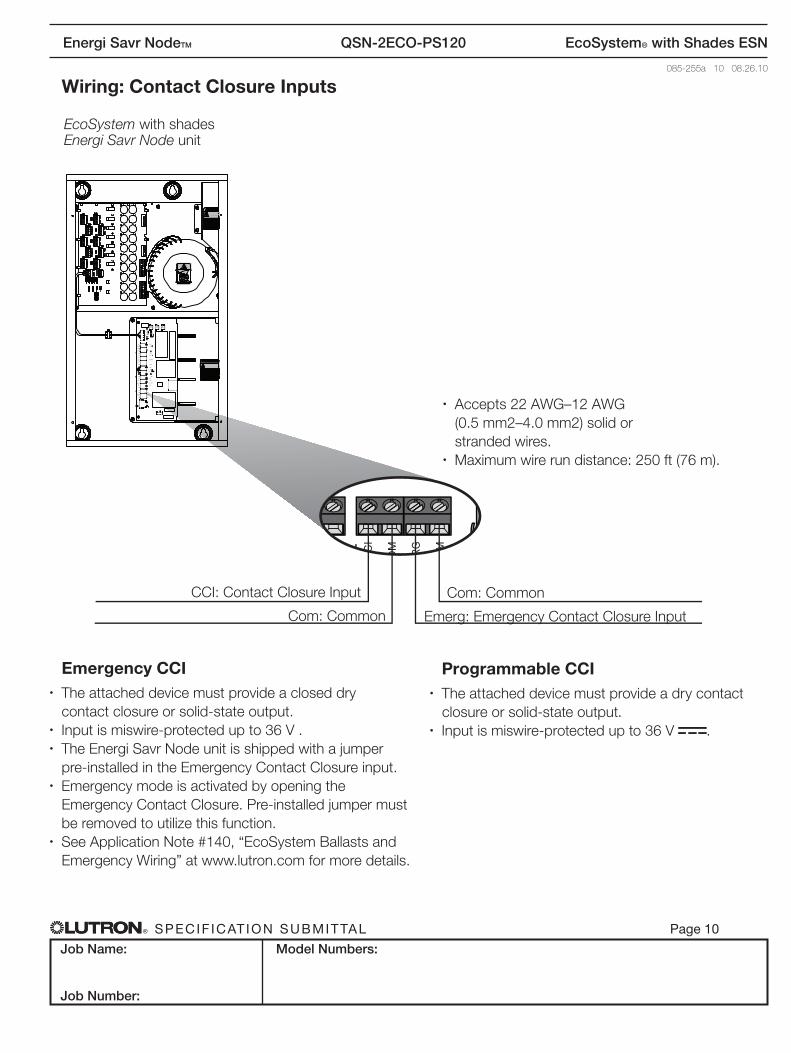
Wiring: Contact Closure Inputs
Emergency CCI• The attached device must provide a closed dry
contact closure or solid-state output.• Input is miswire-protected up to 36 V .• The Energi Savr Node unit is shipped with a jumper
pre-installed in the Emergency Contact Closure input.• Emergency mode is activated by opening the
Emergency Contact Closure. Pre-installed jumper must be removed to utilize this function.• See Application Note #140, “EcoSystem Ballasts and
Emergency Wiring” at www.lutron.com for more details.
Programmable CCI• The attached device must provide a dry contact closure or solid-state output.• Input is miswire-protected up to 36 V .
OM
CC
I
OM RG OM
Com: Common
Com: Common
CCI: Contact Closure Input
Emerg: Emergency Contact Closure Input
EcoSystem with shades Energi Savr Node unit
• Accepts 22 AWG–12 AWG (0.5 mm2–4.0 mm2) solid or
stranded wires.• Maximum wire run distance: 250 ft (76 m).
® Specif icat ion Submittal page 11
Job Name:
Job Number:
Model Numbers:
Energi Savr NodeTM QSN-2ECO-PS120 EcoSystem® with Shades ESN
085-255a 11 08.26.10
PRELIMINARY
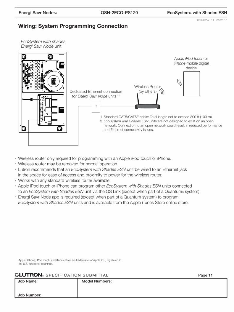
Wiring: System Programming Connection
Wireless Router (by others)
Apple iPod touch or iPhone mobile digital
device
Dedicated Ethernet connection for Energi Savr Node units1,2
EcoSystem with shades Energi Savr Node unit
1 Standard CAT5/CAT5E cable: Total length not to exceed 300 ft (100 m). 2 EcoSystem with Shades ESN units are not designed to exist on an open
network. Connection to an open network could result in reduced performance and Ethernet connectivity issues.
• Wireless router only required for programming with an Apple iPod touch or iPhone.• Wireless router may be removed for normal operation.• Lutron recommends that an EcoSystem with Shades ESN unit be wired to an Ethernet jack
in the space for ease of access and proximity to power for the wireless router.• Works with any standard wireless router available.• Apple iPod touch or iPhone can program other EcoSystem with Shades ESN units connected
to an EcoSystem with Shades ESN unit via the QS Link (except when part of a Quantum® system).• Energi Savr Node app is required (except when part of a Quantum system) to program
EcoSystem with Shades ESN units and is available from the Apple iTunes Store online store.
Apple, iPhone, iPod touch, and iTunes Store are trademarks of Apple Inc., registered inthe U.S. and other countries.


![Dr[1]. Deepak Chopra - Savr Eno Zdravlje](https://img.pdfslide.net/doc/110x75/55721240497959fc0b904d14/dr1-deepak-chopra-savr-eno-zdravlje-55c43c6994a92.jpg)