Embed Size (px)
Citation preview

Instruction ManualR5Rotary Vane Vacuum Pumps
RB 0021 CRC 0021 C
0870146978/A0001_en / Original instructions / Modifications reserved 13/02/2020
Busch Produktions GmbHSchauinslandstraße 1, 79689 MaulburgGermany

Table of Contents
2 / 24 0870146978_RB_RC0021C_A0001_IM_en
Table of Contents1 Safety........................................................................................................................... 3
2 Product Description ..................................................................................................... 4
2.1 Operating Principle...............................................................................................4
2.2 Application ...........................................................................................................5
2.3 Optional Accessories.............................................................................................52.3.1 Gas Ballast Valve........................................................................................62.3.2 Inlet Filter ..................................................................................................62.3.3 Filter pressure gauge..................................................................................6
3 Transport ..................................................................................................................... 6
4 Storage......................................................................................................................... 7
5 Installation................................................................................................................... 8
5.1 Installation Conditions ..........................................................................................8
5.2 Connecting Lines / Pipes ......................................................................................85.2.1 Suction Connection....................................................................................95.2.2 Discharge Connection................................................................................9
5.3 Filling Oil ..............................................................................................................10
5.4 Electrical Connection ............................................................................................115.4.1 Wiring Diagram Single-Phase Motor..........................................................115.4.2 Wiring Diagram Three-Phase Motor ..........................................................12
6 Commissioning............................................................................................................ 13
6.1 Version with Oil Return Valve...............................................................................13
6.2 Conveying Condensable Vapours .........................................................................13
7 Maintenance ................................................................................................................ 14
7.1 Maintenance Schedule..........................................................................................15
7.2 Oil Level Inspection ..............................................................................................15
7.3 Oil Change...........................................................................................................15
7.4 Exhaust Filter Change...........................................................................................17
8 Overhaul...................................................................................................................... 18
9 Decommissioning ........................................................................................................ 18
9.1 Dismantling and Disposal......................................................................................18
10 Spare Parts ................................................................................................................... 19
11 Troubleshooting........................................................................................................... 20
12 Technical Data ............................................................................................................. 22
13 Oil ............................................................................................................................... 22
14 EU Declaration of Conformity ...................................................................................... 23

Safety | 1
0870146978_RB_RC0021C_A0001_IM_en 3 / 24
1 SafetyPrior to handling the machine, this instruction manual should be read and understood. Ifanything needs to be clarified, please contact your Busch representative.
Read this manual carefully before use and keep for future reference.
This instruction manual remains valid as long as the customer does not change anythingon the product.
The machine is intended for industrial use. It must be handled only by technically trainedpersonnel.
Always wear appropriate personal protective equipment in accordance with the localregulations.
The machine has been designed and manufactured according to state-of-the-art meth-ods. Nevertheless, residual risks may remain. This instruction manual highlights potentialhazards where appropriate. Safety notes and warning messages are tagged with one ofthe keywords DANGER, WARNING, CAUTION, NOTICE and NOTE as follows:
DANGER... indicates an imminent dangerous situation that will result in death or serious injuries ifnot prevented.
WARNING... indicates a potentially dangerous situation that could result in death or serious injuries.
CAUTION... indicates a potentially dangerous situation that could result in minor injuries.
NOTICE... indicates a potentially dangerous situation that could result in damage to property.
NOTE... indicates helpful tips and recommendations, as well as information for efficient andtrouble-free operation.

2 | Product Description
4 / 24 0870146978_RB_RC0021C_A0001_IM_en
2 Product DescriptionEF INOUT
GBTL
NP
OSG ODP
OFPMTB DA
Version with gas ballast valve
OS
DA Directional arrow EF Exhaust filter
GB Gas ballast valve IN Suction connection
NP Nameplate MTB Motor terminal box
ODP Oil drain plug OFP Oil fill plug
OS Oil separator OSG Oil sight glass
OUT Discharge connection TL Transport lug
NOTETechnical term.
In this instruction manual, we consider that the term ‘machine’ refers to the ‘vacuumpump’.
NOTEIllustrations
In this instruction manual the illustrations may differ from the machine appearance.
Product Description | 2
0870146978_RB_RC0021C_A0001_IM_en 5 / 24
2.1 Operating Principle
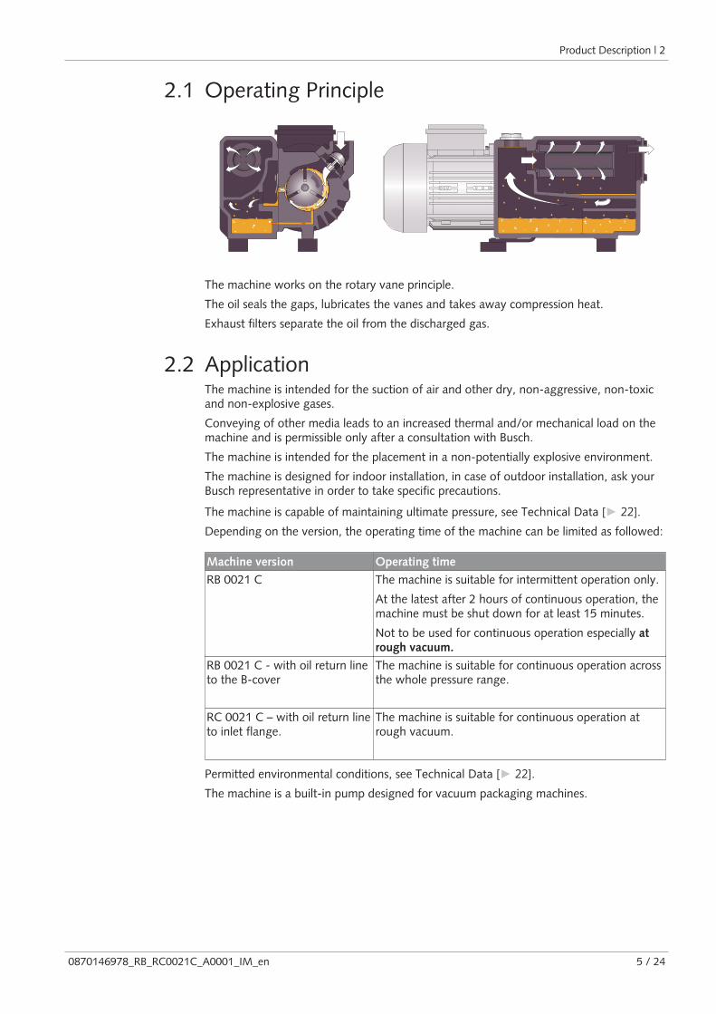
The machine works on the rotary vane principle.
The oil seals the gaps, lubricates the vanes and takes away compression heat.
Exhaust filters separate the oil from the discharged gas.
2.2 ApplicationThe machine is intended for the suction of air and other dry, non-aggressive, non-toxicand non-explosive gases.
Conveying of other media leads to an increased thermal and/or mechanical load on themachine and is permissible only after a consultation with Busch.
The machine is intended for the placement in a non-potentially explosive environment.
The machine is designed for indoor installation, in case of outdoor installation, ask yourBusch representative in order to take specific precautions.
The machine is capable of maintaining ultimate pressure, see Technical Data [► 22].Depending on the version, the operating time of the machine can be limited as followed:
Machine version Operating time
RB 0021 C The machine is suitable for intermittent operation only.
At the latest after 2 hours of continuous operation, themachine must be shut down for at least 15 minutes.
Not to be used for continuous operation especially atrough vacuum.
RB 0021 C - with oil return lineto the B-cover
The machine is suitable for continuous operation acrossthe whole pressure range.
RC 0021 C – with oil return lineto inlet flange.
The machine is suitable for continuous operation atrough vacuum.
Permitted environmental conditions, see Technical Data [► 22].The machine is a built-in pump designed for vacuum packaging machines.
3 | Transport
6 / 24 0870146978_RB_RC0021C_A0001_IM_en
2.3 Optional Accessories
2.3.1 Gas Ballast ValveThe gas ballast valve mixes the process gas with a limited quantity of ambient air tocounteract the condensation of vapour inside the machine.
The gas ballast valve has an influence on the ultimate pressure of the machine, see Tech-nical Data [► 22].
2.3.2 Inlet FilterThe inlet filter protects the machine against dust and other solids in the process gas. Theinlet filter is available with a paper or polyester cartridge.
2.3.3 Filter pressure gaugeUse the filter pressure gauge for checking the degree of clogging of the exhaust filter.
3 Transport
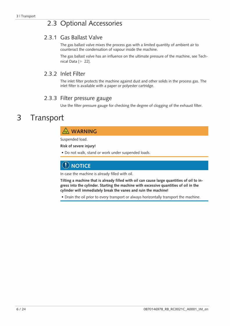
WARNINGSuspended load.
Risk of severe injury!
• Do not walk, stand or work under suspended loads.
NOTICEIn case the machine is already filled with oil.
Tilting a machine that is already filled with oil can cause large quantities of oil to in-gress into the cylinder. Starting the machine with excessive quantities of oil in thecylinder will immediately break the vanes and ruin the machine!
• Drain the oil prior to every transport or always horizontally transport the machine.
Storage | 4
0870146978_RB_RC0021C_A0001_IM_en 7 / 24
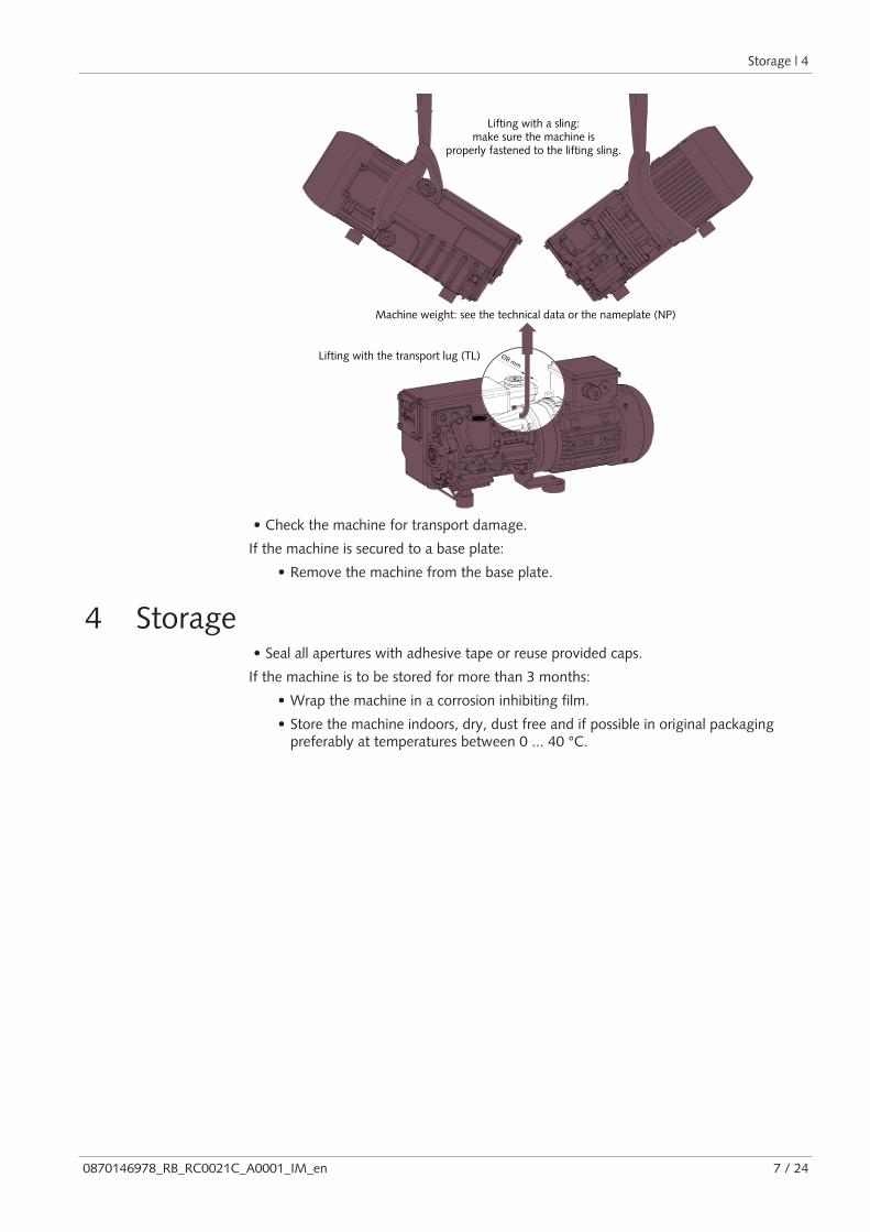
Ø8 mm
Machine weight: see the technical data or the nameplate (NP)
Lifting with the transport lug (TL)
Lifting with a sling:make sure the machine is
properly fastened to the lifting sling.
• Check the machine for transport damage.
If the machine is secured to a base plate:
• Remove the machine from the base plate.
4 Storage• Seal all apertures with adhesive tape or reuse provided caps.
If the machine is to be stored for more than 3 months:
• Wrap the machine in a corrosion inhibiting film.
• Store the machine indoors, dry, dust free and if possible in original packagingpreferably at temperatures between 0 ... 40 °C.

5 | Installation
8 / 24 0870146978_RB_RC0021C_A0001_IM_en
5 Installation
5.1 Installation Conditions
NOTICEUse of the machine outside of the permitted installation conditions.
Risk of premature failure!
Loss of efficiency!
• Take care that the installation conditions are fully complied with.
20 cm
20 cm
20 cm
20 cm
• Make sure that the environment of the machine is not potentially explosive.
• Make sure that the ambient conditions comply with the Technical Data [► 22].• Make sure that the environmental conditions comply with the protection class of the
motor and the electrical instruments.
• Make sure that the installation space or location is vented such that sufficient coolingof the machine is provided.
• Make sure that cooling air inlets and outlets are not covered or obstructed and thatthe cooling air flow is not affected adversely in any other way.
• Make sure that the oil sight glass (OSG) remains easily visible.
• Make sure that enough space remains for maintenance work.
• Make sure that the machine is placed or mounted horizontally, a maximum of 1° inany direction is acceptable.
• Check the oil level, see Oil Level Inspection [► 15].• Make sure that all provided covers, guards, hoods, etc. are mounted.
If the machine is installed at an altitude greater than 1000 meters above sea level:
• Contact your Busch representative, the motor should be derated or the ambienttemperature limited.

Installation | 5
0870146978_RB_RC0021C_A0001_IM_en 9 / 24
5.2 Connecting Lines / Pipes• Remove all protective covers before installation.
• Make sure that the connection lines cause no stress on the machine‘s connection; ifnecessary use flexible joints.
• Make sure that the line size of the connection lines over the entire length is at least aslarge as the connections of the machine.
In case of very long connection lines it is advisable to use larger line sizes in order toavoid a loss of efficiency. Seek advice from your Busch representative.
5.2.1 Suction Connection
NOTICEIngress of foreign objects or liquids.
Risk of damage to the machine!
If the inlet gas contains dust or other foreign solid particles:
• Install a suitable filter (5 micron or less) upstream from the machine.
Connection size(s):
Depending on the specific order, other connection dimensions may apply.
5.2.2 Discharge Connection
CAUTIONThe discharge gas contains small quantities of oil.
Risk to health!
If air is discharged into rooms where persons are present:
• Make sure that sufficient ventilation is provided.
Connection size(s):
Depending on the specific order, other connection dimensions may apply.
• Make sure that the discharged gas will flow without obstruction. Do not shut off orthrottle the discharge line or use it as a pressurised air source.
Unless the aspirated air is discharged to the environment right at the machine:
• Make sure that the discharge line either slopes away from the machine or provide a li-quid separator or a siphon with a drain cock, so that no liquids can flow back into themachine.
5 | Installation
10 / 24 0870146978_RB_RC0021C_A0001_IM_en
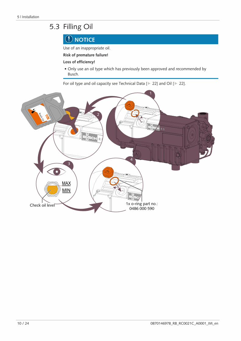
5.3 Filling Oil
NOTICEUse of an inappropriate oil.
Risk of premature failure!
Loss of efficiency!
• Only use an oil type which has previously been approved and recommended byBusch.
For oil type and oil capacity see Technical Data [► 22] and Oil [► 22].
1
4
MAXMIN
3
2
Busch Oil
Check oil level 1x o-ring part no.:0486 000 590

Installation | 5
0870146978_RB_RC0021C_A0001_IM_en 11 / 24
5.4 Electrical Connection
DANGERLive wires.
Risk of electrical shock.
• Electrical installation work must only be executed by qualified personnel.
• Make sure that the power supply for the motor is compatible with the data on thenameplate of the motor.
• The electrical installation must comply with applicable national and internationalstandards.
• Provide a lockable disconnect switch on the power line so that the machine is com-pletely secured during maintenance tasks.
• Provide an overload protection according to EN 60204-1 for the motor.
• Busch recommends installing a D-curve circuit breaker.
• Make sure that the motor of the machine will not be affected by electric or electro-magnetic disturbance from the mains; if necessary seek advice from Busch.
• Connect the protective earth conductor.
• Electrically connect the motor.
5.4.1 Wiring Diagram Single-Phase MotorConnection Scheme of Alternating Current Motor
Explanation of color coding:
BK = black
BN = brown
BU = blue
GN = green
RD = red
YE = yellow

5 | Installation
12 / 24 0870146978_RB_RC0021C_A0001_IM_en
5.4.2 Wiring Diagram Three-Phase Motor
NOTICEIncorrect direction of rotation.
Risk of damage to the machine!
• Operation in the wrong direction of rotation can destroy the machine in a short time!Prior to start-up, ensure that the machine is operated in the right direction.
• Determine the intended direction of rotation with the arrow (stuck on or cast).
• Jog the motor briefly.
• Watch the fan wheel of the motor and determine the direction of rotation just beforethe fan wheel stops.
If the rotation of the motor must be changed:
• Switch any two of the motor phase wires.
Delta connection (low voltage): Star connection (high voltage):
Commissioning | 6
0870146978_RB_RC0021C_A0001_IM_en 13 / 24
6 Commissioning
NOTICEThe machine can be shipped without oil.
Operation without oil will ruin the machine in short time!
• Prior to commissioning, the machine must be filled with oil, see Filling Oil [► 10].
CAUTIONDuring operation the surface of the machine may reach temperatures of more than70°C.
Risk of burns!
• Avoid contact with the machine during and directly after operation.
CAUTIONNoise of running machine.
Risk of damage to hearing!
If persons are present in the vicinity of a non noise insulated machine over extendedperiods:
• Make sure that ear protection is being used.
• Make sure that the installation conditions (see Installation Conditions [► 8]) are met.
• Switch on the machine.
• Make sure that the maximum permissible number of starts does not exceed 12 startsper hour. Those starts should be spread within the hour.
• Make sure that the operating conditions comply with the Technical Data [► 22].• After a few minutes of operation, check the oil level and top up if necessary.
As soon as the machine is operated under normal operating conditions:
• Measure the motor current and record it as reference for future maintenance andtroubleshooting work.
6.1 Version with Oil Return ValveDuring operation oil accumulates at the bottom of the upper chamber of the oil separ-ator, which cannot flow down into the bottom chamber, as long as the machine runs.
After 2 hours of continuous operation, in case of high pressure difference between suc-tion side and pressure side after a shorter period:
• Shut down the machine for at least 15 minutes.
ð The oil can run down from the upper chamber of the oil separator into the bottomchamber

7 | Maintenance
14 / 24 0870146978_RB_RC0021C_A0001_IM_en
6.2 Conveying Condensable VapoursWater vapour within the gas flow is tolerated within certain limits. The conveyance ofother vapours shall be agreed upon with Busch.
If condensable vapours are to be conveyed:
30 minutes
* not included in the scope of delivery
• Close the isolationvalve*
• Warm up the machine• Open the isolation
valve and perform theprocess
• Close the isolationvalve
END
START
30 minutes
7 Maintenance
WARNINGMachines contaminated with hazardous material.
Risk of poisoning!
Risk of infection!
If the machine is contaminated with hazardous material:
• Wear appropriate personal protective equipment.
CAUTIONHot surface.
Risk of burns!
• Prior to any action requiring touching the machine, let the machine cool down first.
NOTICEUsing inappropriate cleaners.
Risk of removing safety stickers and protective paint!
• Do not use incompatible solvents to clean the machine.
CAUTIONFailing to properly maintain the machine.
Risk of injuries!
Risk of premature failure and loss of efficiency!
• Respect the maintenance intervals or ask your Busch representative for service.
• Shut down the machine and lock against inadvertent start up.
• Vent the connected lines to atmospheric pressure.
If necessary:
• Disconnect all connections.

Maintenance | 7
0870146978_RB_RC0021C_A0001_IM_en 15 / 24
7.1 Maintenance ScheduleThe maintenance intervals depend very much on the individual operating conditions. Theintervals given below are desired to be considered as starting values which should beshortened or extended as appropriate. Particularly harsh applications or heavy duty oper-ation, such as high dust loads in the environment or in the process gas, other contamina-tion or ingress of process material, can make it necessary to shorten the maintenance in-tervals significantly.
Maintenance work Interval
Normal application Harsh application
• Check the oil level, see Oil Level Inspec-tion [► 15].
Daily
• Check the machine for oil leaks - in case ofleaks have the machine repaired (contactBusch).
In case an inlet filter is installed:
• Check the inlet filter cartridge, replace it ifnecessary.
Monthly
• Contact Busch for an inspection.If required, overhaul the machine.
Every 5 years
* Service interval for synthetic oil, shorten the interval when using mineral oil, contactBusch Service
7.2 Oil Level Inspection• Shut down the machine.
• When the machine is stopped, wait 1 minute before checking the oil level.
MAX
MIN
MAX
MIN
MAX
MIN
• Fill up if necessary, see Oil Filling [► 10].
7 | Maintenance
16 / 24 0870146978_RB_RC0021C_A0001_IM_en
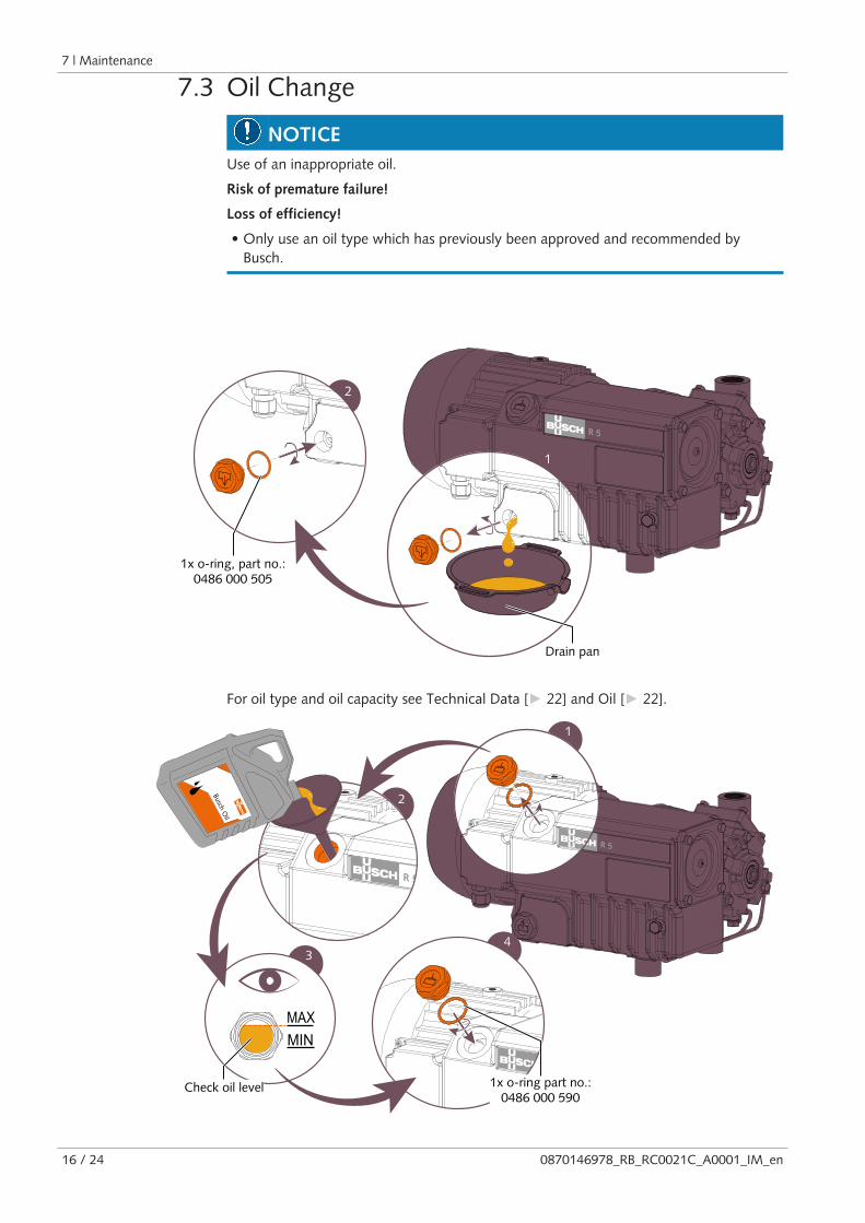
7.3 Oil Change
NOTICEUse of an inappropriate oil.
Risk of premature failure!
Loss of efficiency!
• Only use an oil type which has previously been approved and recommended byBusch.
1
2
Drain pan
1x o-ring, part no.:0486 000 505
For oil type and oil capacity see Technical Data [► 22] and Oil [► 22].
1
4
MAXMIN
3
2
Busch Oil
Check oil level 1x o-ring part no.:0486 000 590

Maintenance | 7
0870146978_RB_RC0021C_A0001_IM_en 17 / 24
7.4 Exhaust Filter Change
4x
1
2
10 mm wrench
1x exhaust filter (EF)
1
4x
2
O-ring
10 mm wrench
1x exhaust filter (EF), part no.: 0532 140 155Busch genuine spare parts
1x flat gasketpart no.: 0480 000 112
8 | Overhaul
18 / 24 0870146978_RB_RC0021C_A0001_IM_en
8 OverhaulIn case of the machine having conveyed gas that was contaminated with foreign materi-als which are dangerous to health:
• Decontaminate the machine as much as possible and state the contaminationstatus in a ‘Declaration of Contamination’.
Busch will only accept machines that come with a completely filled in and legally bindingsigned ‘Declaration of Contamination’.(Form downloadable from www.buschvacuum.com)
NOTICEImproper assembly.
Risk of premature failure!
Loss of efficiency!
• It is highly recommended that any dismantling of the machine that goes beyond any-thing that is described in this manual should be done through Busch.
WARNINGMachines contaminated with hazardous material.
Risk of poisoning!
Risk of infection!
If the machine is contaminated with hazardous material:
• Wear appropriate personal protective equipment.
9 Decommissioning• Shut down the machine and lock against inadvertent start up.
• Vent the connected lines to atmospheric pressure.
• Disconnect all connections.
If the machine is going to be stored:
• See Storage [► 7].
9.1 Dismantling and Disposal• Drain the oil.
• Remove the exhaust filters.
• Remove the oil filter.
• Separate special waste from the machine.
• Dispose of special waste in compliance with applicable regulations.
• Dispose of the machine as scrap metal.

Spare Parts | 10
0870146978_RB_RC0021C_A0001_IM_en 19 / 24
10 Spare Parts
NOTICEUse of non-Busch genuine spare parts.
Risk of premature failure!
Loss of efficiency!
• The exclusive use of Busch genuine spare parts and consumables is recommended forthe correct functioning of the machine and to validate the warranty.
Spare part kit Description Part no.
Service kit Exhaust filter with O-ring
Exhaust cover plate gasket
Seal ring for oil fill plug
Seal ring for oil drain plug
0992121241
Gasket kit All seals 0990146959
Overhaul kit Wearing parts
Gasket kit
0993146964
If other parts are required:
• Contact your Busch representative for the detailed spare parts list.

11 | Troubleshooting
20 / 24 0870146978_RB_RC0021C_A0001_IM_en
11 Troubleshooting
DANGERLive wires.
Risk of electrical shock.
• Electrical installation work must only be executed by qualified personnel.
CAUTIONHot surface.
Risk of burns!
• Prior to any action requiring touching the machine, let the machine cool down first.
EF ISGB CPL
Problem Possible Cause Remedy
The machine does not start. The motor is not suppliedwith the correct voltage.
• Check the power supply.
The motor is defective. • Replace the motor.
The coupling (CPL) is de-fective.
• Replace the coupling(CPL).
The machine does not reachthe usual pressure on thesuction connection.
Oil level too low. • Top up oil.
The inlet screen (IS) is par-tially clogged.
• Clean the inlet screen (IS).
The inlet filter cartridge (op-tional) is partially clogged.
• Replace the inlet filtercartridge.
Internal parts are worn ordamaged.
• Repair the machine (con-tact Busch).
The machine runs very nois-ily.
Worn coupling (CPL). • Replace the coupling(CPL).
Stuck vanes. • Repair the machine (con-tact Busch).
Defective bearings. • Repair the machine (con-tact Busch).

Troubleshooting | 11
0870146978_RB_RC0021C_A0001_IM_en 21 / 24
The machine runs too hot. Insufficient cooling. • Remove dust and dirtfrom the machine.
• Check the cooling fan.
Ambient temperature toohigh.
• Observe the permittedambient temperature.
Oil level too low. • Top up oil.
The exhaust filters (EF) arepartially clogged.
• Replace the exhaust filters(EF).
The machine fumes or ex-pels oil droplets through thegas discharge.
The exhaust filters (EF) arepartially clogged.
• Replace the exhaust filters(EF).
An exhaust filter (EF) with o-ring is not fitted properly.
• Ensure the correct posi-tion of the exhaust filters(EF) and the o-rings.
The float valve (FV) doesnot work properly.
• Check the float valve andthe oil pipe for clogging.Remove the clogging.
Version with oil return valve:
The machine runs for morethan 2 hours without inter-ruption.
• Regularly shut down themachine for short periodsof time (see Version withOil Return Valve [► 13]).
Abnormal oil consumption. Oil leaks. • Replace seals (contactBusch).
The float valve (FV) doesnot work properly.
• Check float valve and theoil return line, repair it ifnecessary (contact Busch).
The machine runs at atmo-spheric pressure for a longperiod.
• Make sure that the ma-chine operates under va-cuum.
The oil is black. Oil change intervals are toolong.
• Flush the machine (con-tact Busch).
The inlet filter (optional) isdefective.
• Replace the inlet filter.
The machine runs too hot. • See problem "The ma-chine runs too hot".
The oil is emulsified. The machine sucked in li-quids or significant amountsof vapour.
• Flush the machine (con-tact Busch).
• Clean the filter of the gasballast valve (GB).
• Modify the operationalmode (see ConveyingCondensable Vapours[► 13]).
For the solution of problems not mentioned in the troubleshooting chart contact yourBusch representative.

12 | Technical Data
22 / 24 0870146978_RB_RC0021C_A0001_IM_en
12 Technical DataRB 0021 C RC 0021 C
Nominal pumping speed(50Hz / 60Hz)
m³/h 20 /24 20 /24
Ultimate pressure(without gas ballast valve)
hPa (mbar) abs. 2.0 20
Ultimate pressure(with gas ballast valve)
hPa (mbar) abs. 2.0 20
Nominal motor speed(50Hz /60Hz)
min-1 3000 / 3600
Nominal motor rating(50Hz /60Hz)
kW 0.75 / 0.9 0.75 / 0.9
Power consumption at 100 mbar(50Hz /60Hz)
kW 0.78 / 1.03 0.78 / 1.03
Power consumption at ultimate pres-sure(50Hz /60Hz)
kW 0.56 / 0.79 0.7 / 0.9
Sound level (EN ISO 2151)(50Hz /60Hz)
dB(A) 66 / 72
Ambient temperature range °C See Oil [► 22]Ambient pressure Atmospheric pressure
Oil capacity l 0.45
Weight approx. kg ~20
13 OilVM 068 VSA 068 VSB 068
ISO-VG 68 68 68
Oil type Mineral oil Synthetic oil Synthetic oil
Ambient temperature range [°C] 5… 35 5… 40 5… 40
Part number 1 L packaging 0831 102 492 0831 163 964 0831 168 347
Part number 5 L packaging 0831 102 493 0831 163 965 0831 168 348
To know which oil has been filled in the machine, please refer to the nameplate (NP).

EU Declaration of Conformity | 14
0870146978_RB_RC0021C_A0001_IM_en 23 / 24
14 EU Declaration of ConformityThis Declaration of Conformity and the CE-mark affixed to the nameplate are valid for the machine within theBusch scope of delivery. This Declaration of Conformity is issued under the sole responsibility of the manufacturer.When this machine is integrated into a superordinate machinery the manufacturer of the superordinate machinery(this can be the operating company, too) must conduct the conformity assessment process for the superordinatemachine or plant, issue the Declaration of Conformity for it and affix the CE-mark.
The manufacturer Busch Produktions GmbHSchauinslandstr. 1DE-79689 Maulburg
declares that the machine(s): R5 RB 0021 C; RC 0021 C
has (have) been manufactured in accordance with the European Directives:
– ‘Machinery’ 2006/42/EC
– ‘Electromagnetic Compatibility’ 2014/30/EU
– ‘RoHS’ 2011/65/EU + Commission Delegated Directive (EU) 2015/863, restriction of the use of certain haz-ardous substances in electrical and electronic equipment
and the following standards:
Standard Title of the Standard
DIN EN 1012-1:2011-02 Compressors and vacuum pumps - Safety requirements - Part 1: Air compressors
DIN EN 1012-2:2011-12 Compressors and vacuum pumps - Safety requirements - Part 2: Vacuum pumps
DIN EN 1012-3:2014-04 Compressors and vacuum pumps - Safety requirements - Part 3: Process compressors
DIN EN ISO12100:2011-03
Safety of machinery - General principles for design - Risk assessment and risk reduction
DIN EN ISO13857:2008-06
Safety of machinery - Safety distances to prevent hazard zones being reached by upperand lower limbs
DIN EN 60204-1:2007-06 Safety of machinery - Electrical equipment of machines - Part 1: General requirements
DIN EN61000-6-4:2011-09
Electromagnetic compatibility (EMC) - Part 6-4: Generic standards - Emission standardfor industrial environments
DIN EN61000-6-2:2016-05
Electromagnetic compatibility (EMC) - Part 6-2: Generic standards - Immunity standardfor industrial environments
EN ISO 2151:2009-01 Acoustics - Noise test code for compressors and vacuum pumps - Engineering method(grade 2)
(1) In case control systems are integrated.
Person authorised to compile the technical file: Gerd RohwederBusch Dienste GmbHSchauinslandstr. 1DE-79689 Maulburg
Maulburg, 18.11.2019
Dr. Martin Gutmann
General Manager

Argentinawww.buschvacuum.com/[email protected]
Australiawww.buschvacuum.com/[email protected]
Austriawww.buschvacuum.com/[email protected]
Bangladeshwww.buschvacuum.com/[email protected]
Belgiumwww.buschvacuum.com/[email protected]
Brazilwww.buschvacuum.com/[email protected]
Canadawww.buschvacuum.com/[email protected]
Chilewww.buschvacuum.com/[email protected]
Chinawww.buschvacuum.com/cn/[email protected]
Colombiawww.buschvacuum.com/[email protected]
Czech Republicwww.buschvacuum.com/[email protected]
Denmarkwww.buschvacuum.com/[email protected]
Finlandwww.buschvacuum.com/[email protected]
Francewww.buschvacuum.com/[email protected]
Germanywww.buschvacuum.com/[email protected]
Hungarywww.buschvacuum.com/[email protected]
Indiawww.buschvacuum.com/[email protected]
Irelandwww.buschvacuum.com/[email protected]
Israelwww.buschvacuum.com/[email protected]
Italywww.buschvacuum.com/[email protected]
Japanwww.buschvacuum.com/[email protected]
Koreawww.buschvacuum.com/[email protected]
Mexicowww.buschvacuum.com/[email protected]
Netherlandswww.buschvacuum.com/[email protected]
New Zealandwww.buschvacuum.com/[email protected]
Norwaywww.buschvacuum.com/[email protected]
Peruwww.buschvacuum.com/[email protected]
Polandwww.buschvacuum.com/[email protected]
Portugalwww.buschvacuum.com/[email protected]
Romaniawww.buschvacuum.com/[email protected]
Russiawww.buschvacuum.com/[email protected]
Singaporewww.buschvacuum.com/[email protected]
South Africawww.buschvacuum.com/[email protected]
Spainwww.buschvacuum.com/[email protected]
Swedenwww.buschvacuum.com/[email protected]
Switzerlandwww.buschvacuum.com/[email protected]
Taiwanwww.buschvacuum.com/[email protected]
Thailandwww.buschvacuum.com/[email protected]
Turkeywww.buschvacuum.com/[email protected]
United Arab Emirateswww.buschvacuum.com/[email protected]
United Kingdomwww.buschvacuum.com/[email protected]
USAwww.buschvacuum.com/[email protected]
www.buschvacuum.com
Busch Vacuum Pumpsand SystemsAll over the World in Industry
0870146978/A0001_en / © Busch Produktions GmbH